C4000 Micro, C4000 Basic Plus, C4000 Basic, C4000 Eco
72
OPERATING INSTRUCTIONS C4000 Micro, C4000 Basic Plus, C4000 Basic, C4000 Eco Safety light curtain en
Transcript of C4000 Micro, C4000 Basic Plus, C4000 Basic, C4000 Eco
O P E R A T I N G I N S T R U C T I O N S
C4000 Micro, C4000 Basic Plus,C4000 Basic, C4000 Eco
Safety light curtain
en

Operating Instructions
C4000 Micro/Basic/Basic Plus/Eco
2 © SICK AG • Industrial Safety Systems • Germany • All rights reserved 8009423/YT79/2016-03-14Subject to change without notice
This document is protected by the law of copyright, whereby all rights established therein remain with the com-pany SICK AG. Reproduction of this document or parts of this document is only permissible within the limits of thelegal determination of Copyright Law. Alteration or abridgement of the document is not permitted without the ex-plicit written approval of the company SICK AG.

Operating Instructions
C4000 Micro/Basic/Basic Plus/Eco
8009423/YT79/2016-03-14 © SICK AG • Industrial Safety Systems • Germany • All rights reserved 3Subject to change without notice
List of contents
List of contents1 About this document....................................................................................................5
1.1 Function of this document................................................................................51.2 Target group .....................................................................................................51.3 Depth of information ........................................................................................51.4 Scope................................................................................................................61.5 Abbreviations....................................................................................................61.6 Symbols used ...................................................................................................6
2 On safety.......................................................................................................................82.1 Qualified safety personnel................................................................................82.2 Applications of the device.................................................................................82.3 Correct use .......................................................................................................92.4 General safety notes and protective measures................................................92.5 Protection of the environment........................................................................10
3 Product description....................................................................................................113.1 Special features..............................................................................................113.2 Operating principle of the device....................................................................12
3.2.1 Components of the device.............................................................123.2.2 The light curtain principle..............................................................12
3.3 Examples of range of use ...............................................................................133.4 Configurable functions....................................................................................13
3.4.1 Restart interlock............................................................................143.4.2 External device monitoring (EDM) .................................................153.4.3 Scanning range .............................................................................163.4.4 Sender test....................................................................................17
3.5 Status indicators.............................................................................................173.5.1 Status indicators of the sender .....................................................173.5.2 Status indicators of the receiver ...................................................18
4 Installation and mounting..........................................................................................194.1 Determining the safety distance.....................................................................19
4.1.1 Safety distance from the hazardous point.....................................194.1.2 Minimum distance to reflective surfaces ......................................22
4.2 Protection from affecting systems in close proximity .....................................234.3 Steps for mounting the device........................................................................24
4.3.1 Mounting with swivel mount bracket.............................................254.3.2 Mounting with side bracket...........................................................27
5 Electrical installation.................................................................................................295.1 System connection C4000 Basic (M26 × 6 + FE) ...........................................315.2 System connection C4000 Eco (M12 × 4 + FE) ..............................................315.3 System connection C4000 Micro/Basic Plus (M12 × 7 + FE) .........................325.4 External device monitoring (EDM) ..................................................................335.5 Reset button...................................................................................................345.6 Test input (sender test) ..................................................................................345.7 Switching examples........................................................................................35
5.7.1 C4000 Basic on UE48-20S/UE48-30S with restart interlockand EDM........................................................................................35
5.7.2 C4000 Micro/Basic on UE10-30S without restart interlock,with EDM .......................................................................................36

Operating Instructions
C4000 Micro/Basic/Basic Plus/Eco
4 © SICK AG • Industrial Safety Systems • Germany • All rights reserved 8009423/YT79/2016-03-14Subject to change without notice
List of contents
6 Commissioning .......................................................................................................... 376.1 Display sequence during start-up .................................................................. 376.2 Aligning sender and receiver.......................................................................... 376.3 Test notes ...................................................................................................... 38
6.3.1 Tests before the first commissioning............................................ 386.3.2 Regular inspection of the protective device by qualified
safety personnel ........................................................................... 386.3.3 Daily functional checks of the protective device........................... 39
7 Configuration ............................................................................................................. 407.1 Delivery status ............................................................................................... 407.2 Activating the restart interlock....................................................................... 407.3 Activating external device monitoring ............................................................ 407.4 Start-up configuration .................................................................................... 40
8 Care and maintenance .............................................................................................. 42
9 Fault diagnosis .......................................................................................................... 439.1 What to do in case of faults ........................................................................... 439.2 SICK Support.................................................................................................. 439.3 Error displays of the diagnostics LEDs........................................................... 439.4 Error displays of the 7-segment display ......................................................... 44
10 Technical specifications............................................................................................ 4510.1 Data sheet ..................................................................................................... 4510.2 Response time ............................................................................................... 4910.3 Table of weights............................................................................................. 50
10.3.1 C4000 Basic/Micro/Eco............................................................... 5010.3.2 Deflector mirrors PNS75 and PNS125 ......................................... 50
10.4 Dimensional drawings.................................................................................... 5110.4.1 C4000 Basic/Basic Plus/Eco ....................................................... 5110.4.2 C4000 Micro................................................................................. 5210.4.3 Swivel mount bracket ................................................................... 5310.4.4 Side bracket.................................................................................. 5310.4.5 Deflector mirror PNS75 ................................................................ 5410.4.6 Deflector mirror PNS125.............................................................. 55
11 Ordering information ................................................................................................. 5611.1 Delivery .......................................................................................................... 5611.2 C4000 Basic (M26 × 6 + FE).......................................................................... 5711.3 C4000 Eco (M12 × 4 + FE)............................................................................. 5811.4 C4000 Basic Plus (M12 × 7 + FE) .................................................................. 5911.5 C4000 Micro.................................................................................................. 6011.6 Additional front screen (weld spark guard) .................................................... 6111.7 Deflector mirror.............................................................................................. 62
11.7.1 Deflector mirror PNS75 for protective field width0 … 5.4 m (total) ........................................................................... 62
11.7.2 Deflector mirror PNS125 for protective field width4 … 5.4 m (total) ........................................................................... 62
11.8 Accessories.................................................................................................... 63
12 Annex ......................................................................................................................... 6512.1 Compliance with EU directives....................................................................... 6512.2 Checklist for the manufacturer ...................................................................... 6612.3 List of tables .................................................................................................. 6712.4 List of illustrations.......................................................................................... 68

Operating Instructions Chapter 1
C4000 Micro/Basic/Basic Plus/Eco
8009423/YT79/2016-03-14 © SICK AG • Industrial Safety Systems • Germany • All rights reserved 5Subject to change without notice
About this document
1 About this documentPlease read this chapter carefully before working with this documentation and the safetylight curtain C4000 Micro, C4000 Basic Plus, C4000 Basic or the C4000 Eco.
1.1 Function of this documentThese operating instructions are designed to address the technical personnel of themachine manufacturer or the machine operator in regards to safe mounting, installation,electrical installation, commissioning, operation and maintenance of the safety lightcurtain C4000 Micro, C4000 Basic Plus, C4000 Basic or C4000 Eco.
These operating instructions do not provide instructions for operating machines on whichthe safety light curtain is, or will be, integrated. Information on this is to be found in theappropriate operating instructions of the machine.
1.2 Target groupThese operating instructions are addressed to planning engineers, developers and theoperators of plant and systems which are to be protected by one or several safety lightcurtains C4000. It also addresses people who integrate the C4000 into a machine, initia-lise its use, or who are in charge of servicing and maintaining the device.
1.3 Depth of informationThese operating instructions contain information on:
installation and mounting
electrical installation
commissioning
care and maintenance
fault, error diagnosis andtroubleshooting
part numbers
conformity and approval
of the safety light curtain C4000.
Planning and using protective devices such as the C4000 also require specific technicalskills which are not detailed in this documentation.
When operating the C4000, the national, local and statutory rules and regulations must beobserved.
General information on accident prevention using opto-electronic protective devices canbe found in the brochure “Safe Machines with opto-electronic protective devices”.
We also refer you to the SICK homepage on the Internet at: www.sick.com
Here you will find information on:
sample applications
a list of frequently asked questions about the C4000
these operating instructions in different languages for viewing and printing
certificates on the prototype test, the EU declaration of conformity and other documents
Note
Chapter 1 Operating Instructions
C4000 Micro/Basic/Basic Plus/Eco
6 © SICK AG • Industrial Safety Systems • Germany • All rights reserved 8009423/YT79/2016-03-14Subject to change without notice
About this document
1.4 ScopeThis document is an original document.
These operating instructions only apply to the safety light curtains C4000 Basic,C4000 Basic Plus, C4000 Micro and C4000 Eco with one of the following entries on thetype label in the field Operating Instructions:
8009410/N082
8009410/0855
8009410/TI70
8009410/YT79
This document is part of SICK part number 8009410 (operating instructions “Safety lightcurtain C4000 Micro, C4000 Basic Plus, C4000 Basic, C4000 Eco” in all availablelanguages).
1.5 AbbreviationsElectro-sensitive protective equipment (e.g. C4000)
Output signal switching device
1.6 Symbols usedRecommendations are designed to give you some assistance in your decision-makingprocess with respect to a certain function or a technical measure.
Refer to notes for special features of the device.
Display indicators show the status of the 7-segment display of sender or receiver:8 Constant indication of characters, e.g. 9∋ Flashing indication of characters, e.g. 8κ?1 Alternating indication of characters, e.g. L and 2
LED symbols describe the state of a diagnostics LED. Examples:Ν Red The red LED is illuminated constantly.∏ Yellow The yellow LED is flashing.ν Green The green LED is off.
Instructions for taking action are shown by an arrow. Carefully read and follow theinstructions for action.
Warning!
A warning notice indicates an actual or potential risk or health hazard. They are designedto help you to prevent accidents.
Read carefully and follow the warnings!
Sender and receiver
In drawings and diagrams, the symbol ρ denotes the sender and the symbol θ denotesthe receiver.
Note
ESPE
OSSD
Recommendation
Note
∋, κ?1
Ν Red, ∏ Yellow,ν Green
= Take action …
WARNING
ρ θ

Operating Instructions Chapter 1
C4000 Micro/Basic/Basic Plus/Eco
8009423/YT79/2016-03-14 © SICK AG • Industrial Safety Systems • Germany • All rights reserved 7Subject to change without notice
About this document
The term “dangerous state”
The dangerous state (standard term) of the machine is always shown in the drawings anddiagrams of this document as the movement of a machine part. In practical operation,there may be a number of different dangerous states:
machine movements
electrical conductors
visible or invisible radiation
a combination of several risks and hazards

Chapter 2 Operating Instructions
C4000 Micro/Basic/Basic Plus/Eco
8 © SICK AG • Industrial Safety Systems • Germany • All rights reserved 8009423/YT79/2016-03-14Subject to change without notice
On safety
2 On safetyThis chapter deals with your own safety and the safety of the equipment operators.
⋅ Please read this chapter carefully before working with the C4000 or with the machineprotected by the C4000.
2.1 Qualified safety personnelThe safety light curtain C4000 must be installed, commissioned and serviced only byqualified safety personnel. Qualified safety personnel are defined as persons who
have undergone the appropriate technical training
and
who have been instructed by the responsible machine operator in the operation of themachine and the current valid safety guidelines
and
who have access to these operating instructions.
2.2 Applications of the deviceThe safety light curtain C4000 is an electro-sensitive protective equipment (ESPE). Thephysical resolution is 14 or 30 mm with a maximum protective field width of 6 metres. Therealisable protective field height is between 300 and 1,800 mm for the C4000 Basic/Ecoand between 150 and 1,200 mm for the C4000 Micro.
The device is a Type 4 ESPE as defined by IEC 61 496-1 and -2 and is therefore allowed foruse with controls in safety category 4 in compliance with EN ISO 13 849-1. The device issuitable for
Hazardous point protection (finger and hand protection)
Hazardous area protection
Access protection
Access to the hazardous point must be allowed only through the protective field. Theplant/system is not allowed to start as long as personnel are within the hazardous area.Refer to chapter 3.3 “Examples of range of use” on page 13 for an illustration of the pro-tection modes.
Only use the safety light curtain as an indirect safety measure!
An opto-electronic protective device provides indirect protection, e.g., by switching off thepower at the source of the hazard. It cannot provide protection from parts thrown out, norfrom emitted radiation. Transparent objects are not detected.
Depending on the application, mechanical protective devices may be required in additionto the safety light curtain.
The safety light curtain C4000 Basic, C4000 Micro or C4000 Eco operates as a stand-alone system, comprising a sender and receiver. It cannot be combined with other C4000systems, e.g. C4000 Advanced.
WARNING
Note

Operating Instructions Chapter 2
C4000 Micro/Basic/Basic Plus/Eco
8009423/YT79/2016-03-14 © SICK AG • Industrial Safety Systems • Germany • All rights reserved 9Subject to change without notice
On safety
2.3 Correct useThe safety light curtain C4000 must be used only as defined in chapter 2.2 “Applicationsof the device”. It must be used only by qualified personnel and only on the machine whereit has been installed and initialised by qualified safety personnel in accordance with theseoperating instructions.
If the device is used for any other purposes or modified in any way — also during mountingand installation — any warranty claim against SICK AG shall become void.
2.4 General safety notes and protective measures
Safety notes
Please observe the following procedures in order to ensure the correct and safe use of thesafety light curtain C4000.
The national/international rules and regulations apply to the installation, commission-ing, use and periodic technical inspections of the safety light curtain, in particular:
– Machine Directive– Equipment Usage Directive– the work safety regulations/safety rules– other relevant health and safety regulationsManufacturers and operators of the machine with which the safety light curtain is usedare responsible for obtaining and observing all applicable safety regulations and rules.
The notices, in particular the test regulations (see “Test notes” on page 38) of theseoperating instructions (e.g. on use, mounting, installation or integration into the existingmachine controller) must be observed.
The tests must be carried out by qualified safety personnel or specially qualified andauthorised personnel and must be recorded and documented to ensure that the testscan be reconstructed and retraced at any time.
The operating instructions must be made available to the operator of the machinewhere the safety light curtain C4000 is fitted. The machine operator is to be instructedin the use of the device by qualified safety personnel and must be instructed to read theoperating instructions.
The external voltage supply of the device (SELV/PELV) must be capable of bufferingbrief mains voltage failures of 20 ms as specified in EN 60 204-1. Suitable powersupplies are available as accessories from SICK (SICK Power Supply 50 W (Part number7028789)/SICK Power Supply 95 W (Part number 7028790)).
WARNING
Chapter 2 Operating Instructions
C4000 Micro/Basic/Basic Plus/Eco
10 © SICK AG • Industrial Safety Systems • Germany • All rights reserved 8009423/YT79/2016-03-14Subject to change without notice
On safety
2.5 Protection of the environmentThe safety light curtain C4000 has been designed to minimise environmental impact. Ituses only a minimum of power and natural resources.
At work, always act in an environmentally responsible manner. For this reason please notethe following information on disposal.
Disposal
⋅ Always dispose of unserviceable or irreparable devices in compliance withlocal/national rules and regulations with respect to waste disposal.
We would be pleased to be of assistance on the disposal of this device. Contact your localSICK representative.
Note
Operating Instructions Chapter 3
C4000 Micro/Basic/Basic Plus/Eco
8009423/YT79/2016-03-14 © SICK AG • Industrial Safety Systems • Germany • All rights reserved 11Subject to change without notice
Product description
3 Product descriptionThis chapter provides information on the special features and properties of the safety lightcurtain C4000. It describes the construction and the operating principle of the device, inparticular the different operating modes.
⋅ Please read this chapter before mounting, installing and commissioning the device.
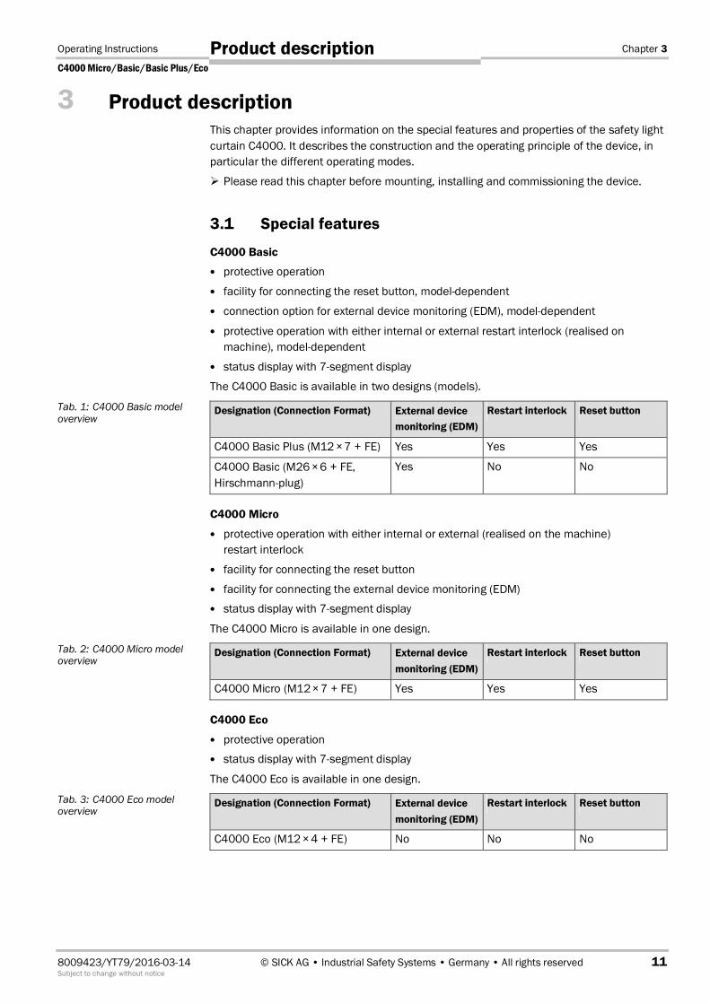
3.1 Special features
C4000 Basic
protective operation
facility for connecting the reset button, model-dependent
connection option for external device monitoring (EDM), model-dependent
protective operation with either internal or external restart interlock (realised onmachine), model-dependent
status display with 7-segment display
The C4000 Basic is available in two designs (models).
Designation (Connection Format) External devicemonitoring (EDM)
Restart interlock Reset button
C4000 Basic Plus (M12 × 7 + FE) Yes Yes Yes
C4000 Basic (M26 × 6 + FE,Hirschmann-plug)
Yes No No
C4000 Micro
protective operation with either internal or external (realised on the machine)restart interlock
facility for connecting the reset button
facility for connecting the external device monitoring (EDM)
status display with 7-segment display
The C4000 Micro is available in one design.
Designation (Connection Format) External devicemonitoring (EDM)
Restart interlock Reset button
C4000 Micro (M12 × 7 + FE) Yes Yes Yes
C4000 Eco
protective operation
status display with 7-segment display
The C4000 Eco is available in one design.
Designation (Connection Format) External devicemonitoring (EDM)
Restart interlock Reset button
C4000 Eco (M12 × 4 + FE) No No No
Tab. 1: C4000 Basic modeloverview
Tab. 2: C4000 Micro modeloverview
Tab. 3: C4000 Eco modeloverview

Chapter 3 Operating Instructions
C4000 Micro/Basic/Basic Plus/Eco
12 © SICK AG • Industrial Safety Systems • Germany • All rights reserved 8009423/YT79/2016-03-14Subject to change without notice
Product description
3.2 Operating principle of the device
3.2.1 Components of the device
Please refer to chapter 10 “Technical specifications” on page 45 for the data sheet.Please refer to pages 51 ff. for the dimensional drawings.
3.2.2 The light curtain principle
The safety light curtain C4000 consists of a sender and a receiver (Fig. 1). Between thesetwo units is the protective field, defined as the protective field height and the protectivefield width.
The construction height determines the protective field height of the appropriate system.For the exact protective field height, please see Tab. 21 ff. in chapter 10.4 “Dimensionaldrawings” on page 51.
The protective field width is derived from the dimension of the light path between senderand receiver and must not exceed the maximum rated protective field width (see “Techni-cal specifications” on page 45).
Sender and receiver automatically synchronise themselves optically. An electrical connec-tion between both components is not required.
The C4000 is modular in structure. All optical and electronic components and assembliesare housed in a slim and torsionally rigid housing.
Fig. 1: Components of theC4000
SenderReceiver

Operating Instructions Chapter 3
C4000 Micro/Basic/Basic Plus/Eco
8009423/YT79/2016-03-14 © SICK AG • Industrial Safety Systems • Germany • All rights reserved 13Subject to change without notice
Product description
3.3 Examples of range of use
The safety light curtain C4000 operates correctly as a protective device only if the follow-ing conditions are met:
The control of the machine must be electrical.
The dangerous state of the machine must be transferable at any time into a safe state.
Sender and receiver unit must be so mounted that objects penetrating the hazardousarea are safely identified by the C4000.
The reset button must be fitted outside the hazardous area such that it cannot beoperated by a person working inside the hazardous area. When operating the resetbutton, the operator must have full visual command of the hazardous area.
The statutory and local rules and regulations must be observed when installing andusing the device.
3.4 Configurable functionsThis chapter describes the functions of the safety light curtains C4000 Basic andC4000 Micro.
Test the protective device after any changes!
After each modification to the protective device or its connection, you must check thewhole protective device for effectiveness (see 6.3 on Page 38).
Fig. 2: Protecting hazardouspoints with a safety lightcurtain C4000(left)
Fig. 3: Hazardous areaprotection with a safety lightcurtain C4000(right)
Fig. 4: Access protectionusing a safety light curtainC4000
WARNING

Chapter 3 Operating Instructions
C4000 Micro/Basic/Basic Plus/Eco
14 © SICK AG • Industrial Safety Systems • Germany • All rights reserved 8009423/YT79/2016-03-14Subject to change without notice
Product description
3.4.1 Restart interlock
The C4000 Micro/Basic has an internal restart interlock. The dangerous state of themachine (0) is interrupted if the light path is broken (1), and is not re-enabled (2) untilthe operator presses the reset button.
If you use the C4000 Micro/Basic without internal restart interlock, then you mustimplement the restart interlock externally, i.e. on the machine.
Do not confuse the restart interlock with the starting interlock on the machine. The startinterlock prevents the machine starting after switching on. The restart interlock pre-vents the machine starting again after an error or an interruption in the light path.
When using the C4000 Micro/Basic, you can implement the restart interlock in two diffe-rent ways:
with the internal restart interlock of the C4000 Micro/Basic:The C4000 Micro/Basic controls the restart.
with the restart interlock of the machine (external):The C4000 Micro/Basic has no control over the restart.
The possible combinations are shown in the following table:
Restart interlock ofthe C4000Micro/Basic
Restart interlockof the machine
Permissibleapplication
Deactivated Deactivated Only if the light curtain cannot be stoodbehind. Observe EN 60 204-1!
Deactivated Activated All
Activated Deactivated Only if the light curtain cannot be stoodbehind. Observe EN 60 204-1!
Activated Activated All. The restart interlock of the C4000 Microhandles the reset function (see “Reset”below).
Always configure the application with restart interlock!
Ensure that there is always a restart interlock. The C4000 is unable to verify if the restartinterlock of the machine is operable. If you deactivate both the internal and the machine’srestart interlock, the operators of the machine will be at an acute risk of injury.
The electrical connection of the reset button is described in chapter “Reset button” onpage 34.
Fig. 5: Outline drawing of theprotective operation
Notes
Tab. 4: Permissibleconfiguration of the restartinterlock of the C4000Micro/Basic
WARNING

Operating Instructions Chapter 3
C4000 Micro/Basic/Basic Plus/Eco
8009423/YT79/2016-03-14 © SICK AG • Industrial Safety Systems • Germany • All rights reserved 15Subject to change without notice
Product description
Reset
If you want to activate the restart interlock on the C4000 Micro/Basic (internal) and also arestart interlock on the machine (external), then each restart interlock has its own button.
When actuating the reset button (for the internal restart interlock)
the C4000 Micro/Basic activates the switching outputs
the safety light curtain changes from red to green
Only the external restart interlock prevents the machine from restarting. After pressing thereset button for the C4000 Micro/Basic, the operator must also press the restart buttonfor the machine. If the reset button and the restart button are not pressed in the specifiedsequence, the dangerous state remains disrupted.
The reset button prevents the accidental and inadvertent operation of the external restartbutton. The operator must first acknowledge the dangerous state with the reset button.
The electrical connection of the reset button is described in chapter “Reset button” onpage 34. The configuration of the reset button is described in chapter 7.2 “Activating therestart interlock” on page 40.
3.4.2 External device monitoring (EDM)
C4000 Micro and C4000 Basic have an EDM. The external device monitoring (EDM)checks if the contactors actually de-energise when the protective device responds. If youactivate external device monitoring, then the C4000 checks the contactors after eachinterruption to the light path and prior to machine restart. The EDM can so identify if one ofthe contactors has fused, for instance. In this case
the error message 7 appears in the 7-segment display
the safety light curtain remains red
with the internal restart interlock activated, the safety light curtain uses the flashingLED ∏ Yellow to signal “Reset required”
If the system is unable to change to a safe operational state (e.g. after contactor failure),the system locks and shuts down completely (“Lock-out”). The 7-segment display will thenshow the error message ∋.
The electrical connection for the external device monitoring is described in chapter “Exter-nal device monitoring (EDM)” on page 33. The configuration of the external device moni-toring is described in chapter 7.4 “Start-up configuration” on page 40.
Recommendation
Note

Chapter 3 Operating Instructions
C4000 Micro/Basic/Basic Plus/Eco
16 © SICK AG • Industrial Safety Systems • Germany • All rights reserved 8009423/YT79/2016-03-14Subject to change without notice
Product description
3.4.3 Scanning range
The safety light curtain is available with different scanning ranges. An overview is con-tained in Tab. 6.
Only use devices with a scanning range that matches the protective field width!
If the scanning range is set too low, the light curtain may not switch to green.
If the scanning range is set too great, the light curtain may malfunction. This wouldmean that the operator is at risk.
The additional front screens, which are available as accessories (see page 61), reducethe effective scanning range per additional front screen by 8 %.
Physicalresolution
Available scanningranges
Scanning range with 1additional front screen
Scanning range with 2additional front screens
14 mm 0–2.5 m1–5 m
0–2.3 m0.9–4.6 m
0–2.1 m0.7–4.2 m
30 mm 0–6 m 0–5.5 m 0–5 m
The deflector mirrors available as accessories (see page 62) reduce the overall scan-ning range depending on the number of deflector mirrors in the light path (see section11.7.1 for PNS75 and section 11.7.2 for PNS125).
Do not use deflector mirrors if the formation of droplets or heavy contamination of thedeflector mirrors is to be expected!
The formation of droplets of heavy contamination can be detrimental to the reflectionbehaviour. The protective function of the system will be affected and the system will thusbecome unsafe. This would mean that the operator is at risk.
Deflector mirror 14 mm 30 mm
1 × PNS75 4.4 m 5.0 m
2 × PNS75 2.4 m 3.3 m
1 × PNS125 4.4 m 5.3 m
2 × PNS125 2.8 m 3.8 m
The information in the table relates to 90° beam deflection per mirror and a protectivefield height of 900 mm. If you need more advice on mirror applications, please get in touchwith your contact at SICK.
WARNING
Notes
Tab. 5: Scanning range ofthe C4000 without and withadditional front screen
WARNING
Tab. 6: Scanning range whenusing 1 or 2 deflector mirrors

Operating Instructions Chapter 3
C4000 Micro/Basic/Basic Plus/Eco
8009423/YT79/2016-03-14 © SICK AG • Industrial Safety Systems • Germany • All rights reserved 17Subject to change without notice
Product description
3.4.4 Sender test
The C4000 sender (except C4000 Eco M12 × 4 + FE) has a test input for checking thesender and the related receiver. During the test, the sender no longer emits light beams.Thus, it simulates — for the receiver — an interruption of the protective field.
During the test the sender indicates ν.
The test is successful, if the C4000 receiver switches to red, i.e. the switching outputs(OSSDs) are deactivated.
C4000 sender and receiver are self-testing. You only need to configure the function of thesender test if this is necessary for an older existing application.
In order to perform a sender test, a means of controlling the test input must be available.The electrical connection at the test input is described in chapter 5.6 “Test input (sendertest)” on page 34.
3.5 Status indicatorsThe LEDs and the 7-segment display of sender and receiver signal the operating status ofthe C4000.
3.5.1 Status indicators of the sender
Display Meaning
Ν Yellow Supply voltage OK
δ System error. The device is defective. Replace the sender.
ν The device is in the test mode.
τ Non-coded operation (only after switching on)
Otherdisplays
All other displays are error messages. Please refer to chapter “Faultdiagnosis” on page 43.
Note
Fig. 6: Status indicators ofthe sender
Tab. 7: Status indicators ofthe sender
7-segment display
Yellow
C4000 Micro C4000 Basic/Eco
Chapter 3 Operating Instructions
C4000 Micro/Basic/Basic Plus/Eco
18 © SICK AG • Industrial Safety Systems • Germany • All rights reserved 8009423/YT79/2016-03-14Subject to change without notice
Product description
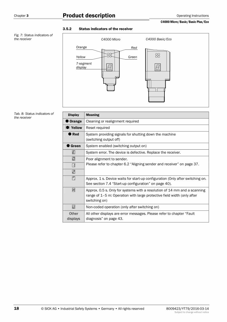
3.5.2 Status indicators of the receiver
Display Meaning
Ν Orange Cleaning or realignment required
∏ Yellow Reset required
Ν Red System providing signals for shutting down the machine(switching output off)
Ν Green System enabled (switching output on)
δ System error. The device is defective. Replace the receiver.
/
0
1
Poor alignment to sender.Please refer to chapter 6.2 “Aligning sender and receiver” on page 37.
∩ Approx. 1 s. Device waits for start-up configuration (Only after switching on.See section 7.4 “Start-up configuration” on page 40).
γ Approx. 0.5 s. Only for systems with a resolution of 14 mm and a scanningrange of 1–5 m: Operation with large protective field width (only afterswitching on)
τ Non-coded operation (only after switching on)
Otherdisplays
All other displays are error messages. Please refer to chapter “Faultdiagnosis” on page 43.
Fig. 7: Status indicators ofthe receiver
Tab. 8: Status indicators ofthe receiver
C4000 Micro C4000 Basic/Eco
Orange
Yellow
Red
Green
7-segmentdisplay

Operating Instructions Chapter 4
C4000 Micro/Basic/Basic Plus/Eco
8009423/YT79/2016-03-14 © SICK AG • Industrial Safety Systems • Germany • All rights reserved 19Subject to change without notice
Installation and mounting
4 Installation and mountingThis chapter describes the preparation and completion of the installation of the safety lightcurtain C4000. The installation and mounting requires two steps:
determining the necessary safety distance
installation with swivel mount or side brackets
The following steps are necessary after mounting and installation: making the electrical connections (chapter 5)
aligning sender and receiver (chapter 6.2)
checking the installation (chapter 6.3)
4.1 Determining the safety distanceThe light curtain must be mounted with the correct safety distance
from the hazardous point
from reflective surfaces
No protective function without large enough safety distance!
The reliable protective effect of the light curtain depends on the system being mountedwith the correct safety distance from the hazardous point.
4.1.1 Safety distance from the hazardous point
A safety distance must be maintained between the light curtain and the hazardous point.This safety distance ensures that the hazardous point can only be reached after the dan-gerous state of the machine has been completely stopped.
The safety distance as defined in EN ISO 13 855 and EN ISO 13 857 depends on:
stopping/run-down time of the machine or system(The stopping/run-down time is shown in the machine documentation or must be deter-mined by taking a measurement.)
response time of the entire protective device, e.g. C4000 (response times see chapter“Response time” on page 49)
reach or approach speed
resolution of the light curtain and/or beam separation
other parameters that are stipulated by the standard depending on the application
Under the authority of OSHA and ANSI the safety distance as specified byANSI B11.19:2003-04, Annex D and Code of Federal Regulations, Volume 29,Part 1910.217 … (h) (9) (v) depends on:
stopping/run-down time of the machine or system(The stopping/run-down time is shown in the machine documentation or must be deter-mined by taking a measurement.)
response time of the entire protective device, e.g. C4000 (response times see chapter“Response time” on page 49)
reach or approach speed
other parameters that are stipulated by the standard depending on the application
WARNING

Chapter 4 Operating Instructions
C4000 Micro/Basic/Basic Plus/Eco
20 © SICK AG • Industrial Safety Systems • Germany • All rights reserved 8009423/YT79/2016-03-14Subject to change without notice
Installation and mounting
How to calculate the safety distance S according to EN ISO 13 855 and EN ISO 13 857:
The following calculation shows an example calculation of the safety distance. Dependingon the application and the ambient conditions, a different calculation may be necessary.
⋅ First, calculate S using the following formula:S = 2000 × T + 8 × (d – 14) [mm]
Where …
T = Stopping/run-down time of the machine+ Response time of the protective device after light path interruption [s]
d = Resolution of the light curtain [mm]
S = Safety distance [mm]
The reach/approach speed is already included in the formula.
⋅ If the result S is ′ 500 mm, then use the determined value as the safety distance.
⋅ If the result S is > 500 mm, then recalculate S as follows:S = 1600 × T + 8 × (d – 14) [mm]
⋅ If the new value S is > 500 mm, then use the newly determined value as the minimumsafety distance.
⋅ If the new value S is ′ 500 mm, then use 500 mm as the minimum safety distance.
Example:
Stopping/run-down time of the machine = 290 msResponse time after light path interruption = 30 msResolution of the light curtain = 14 mmT = 290 ms + 30 ms = 320 ms = 0.32 sS = 2000 × 0.32 + 8 × (14 – 14) = 640 mmS > 500 mm, therefore:S = 1600 × 0.32 + 8 × (14 – 14) = 512 mm
Fig. 8: Safety distance fromthe hazardous point
Note
Hazar-douspoint
Distance to avoidstanding behind the safety curtain ′ 75 mm
Safety distance S (Ds)
Protective field height

Operating Instructions Chapter 4
C4000 Micro/Basic/Basic Plus/Eco
8009423/YT79/2016-03-14 © SICK AG • Industrial Safety Systems • Germany • All rights reserved 21Subject to change without notice
Installation and mounting
How to calculate the safety distance Ds according to ANSI B11.19:2003-04, Annex Dand Code of Federal Regulations, Volume 29, Part 1910.217 … (h) (9) (v):
The following calculation shows an example calculation of the safety distance. Dependingon the application and the ambient conditions, a different calculation may be necessary.
⋅ Calculate Ds using the following formula:Ds = Hs × (Ts + Tc +Tr + Tbm) + Dpf
Where …
Ds = The minimum distance in inches (or millimetres) from the hazardous point to theprotective device
Hs = A parameter in inches/second or millimetres/second, derived from data onapproach speeds of the body or parts of the body. Often 63 inches/second(1600 millimetres/second) is used for Hs.
Ts = Stopping/run down time of the machine tool measured at the final controlelement
Tc = Stopping/run-down time of the control system
Tr = Response time of the entire protective device after light path interruption
Tbm = Additional response time allowed for brake monitor to compensate for wear
Any additional response times must be accounted for in this calculation.
Dpf = An additional distance added to the overall safety distance required. This value isbased on intrusion toward the hazardous point prior to actuation of the electro-sensitive protective equipment (ESPE). Values range from 0.25 inches to 48 in-ches (6 millimetres to 1220 millimeters) or more depending on application.
Example:
In opto-electronic protecting, such as with a perpendicular safety light curtainapplications with object sensitivity (effective resolution) less than 2.5 inches(64 millimetres), the Dpf can be approximated based on the following formula:
Dpf (inches) = 3.4 × (Object Sensitivity – 0.276), but not less than 0.
Note
Note

Chapter 4 Operating Instructions
C4000 Micro/Basic/Basic Plus/Eco
22 © SICK AG • Industrial Safety Systems • Germany • All rights reserved 8009423/YT79/2016-03-14Subject to change without notice
Installation and mounting
4.1.2 Minimum distance to reflective surfaces
The light beams from the sender may be deflected by reflective surfaces. This can result infailure to identify an object.
All reflective surfaces and objects (e.g. material bins) must therefore be located at a mini-mum distance a from the protective field of the system. The minimum distance a dependson the distance D between sender and receiver.
The field of view of the sender and receiver optics is identical.
How to determine the minimum distance from reflective surfaces:
⋅ Determine the distance D [m] sender-receiver.
⋅ Read the minimum distance a [mm] from the graph:
Fig. 9: Minimum distance toreflective surfaces
Note
Fig. 10: Graph, minimumdistance from reflectivesurfaces
Reflective surfaceMinimum distance a
Distance D sender-receiver
Field of view

Operating Instructions Chapter 4
C4000 Micro/Basic/Basic Plus/Eco
8009423/YT79/2016-03-14 © SICK AG • Industrial Safety Systems • Germany • All rights reserved 23Subject to change without notice
Installation and mounting
4.2 Protection from affecting systems in close proximity
Prevent the affection of systems mounted in close proximity
If several safety light curtains operate in close proximity to each other, the sender beamsof one system may interfere with the receiver of another system. This can disrupt the pro-tective function of the system. This would mean that the operator is at risk. You must avoidsuch mounting scenarios or take appropriate measures, e.g. by mounting non-reflectivesight protection walls or by reversing the transmission direction of a system.
WARNING
Fig. 11: Unwantedinfluencing of a 2nd
C4000 system.The receiver θ of the 2nd
system is affected by thebeams of the 1st system.
Fig. 12: Reversing thetransmission direction ofsystems in close proximity.The sender Ρ of the 2nd
system is not affected by thebeams of the 1st system.
Beams of the 1st system
Affected 2nd system
Beams of the 1st system
2nd system with reversed transmission direction

Chapter 4 Operating Instructions
C4000 Micro/Basic/Basic Plus/Eco
24 © SICK AG • Industrial Safety Systems • Germany • All rights reserved 8009423/YT79/2016-03-14Subject to change without notice
Installation and mounting
4.3 Steps for mounting the device
Special features to note during mounting:
⋅ Always mount the sender and receiver parallel to one another.
⋅ During mounting, make sure that sender and receiver are aligned correctly. The opticallens systems of sender and receiver must be located in exact opposition to each other;the display elements must be mounted at the same height. The system plugs of bothdevices must point in the same direction.
⋅ Take suitable measures to attenuate vibration if the shock requirements are above thevalues given in chapter 10.1 “Data sheet” on page 45.
⋅ Observe the safety distance of the system during mounting. On this topic read thechapter “Determining the safety distance” on page 19.
⋅ Mount the safety light curtain such that the hazardous point cannot be reached frombelow, above or behind the safety light curtain and that the light curtain cannot berepositioned.
⋅ Once the system is mounted, one or several of the enclosed self-adhesive safetyinformation labels must be affixed.
– Use only information labels in the language which the operators of the machineunderstand.
– Affix the information labels such that they are easily visible by the operators duringoperation. After attaching additional objects and equipment, the information labelsmust not be concealed from view.
– Affix the information label “Important Notices” to the system in close proximity tosender and receiver.
The senders and receivers can be mounted in two different ways:
mounting with swivel mount bracket
mounting with side bracket
WARNING
Fig. 13: The correctinstallation (above) musteliminate the errors (below)stepping behind, reachingbelow and reaching above.

Operating Instructions Chapter 4
C4000 Micro/Basic/Basic Plus/Eco
8009423/YT79/2016-03-14 © SICK AG • Industrial Safety Systems • Germany • All rights reserved 25Subject to change without notice
Installation and mounting
4.3.1 Mounting with swivel mount bracket
The swivel mount bracket is made of black plastic. The bracket is designed such that sen-der and receiver can still be accurately aligned even after the bracket has been mounted.
The swivel mount bracket is also suitable for mounting the deflector mirrors PNS75 andPNS125 (see chapter 10.4.5 f. on page 54 f.).
⋅ Attach the bolts of the swivel mount bracket with a torque of between 2.5 and 3 Nm.Higher torques can damage the bracket; lower torques provide inadequate protectionagainst vibration.
Note
Fig. 14: Composition of theswivel mount bracket

Chapter 4 Operating Instructions
C4000 Micro/Basic/Basic Plus/Eco
26 © SICK AG • Industrial Safety Systems • Germany • All rights reserved 8009423/YT79/2016-03-14Subject to change without notice
Installation and mounting
⋅ Mount the bolts marked with 0 to 3 on the operator side of the system to ensure thatthey remain accessible after mounting and to allow you to readjust the light curtainlater, if necessary.
⋅ If you wish to use the additional front screen (see “Additional front screen (weld sparkguard)” on page 61), make sure that the curved side of the device remains accessibleafter mounting.
Fig. 15: Mounting sender andreceiver using swivel mountbrackets
Notes
0
1
2
3
Operating Instructions Chapter 4
C4000 Micro/Basic/Basic Plus/Eco
8009423/YT79/2016-03-14 © SICK AG • Industrial Safety Systems • Germany • All rights reserved 27Subject to change without notice
Installation and mounting
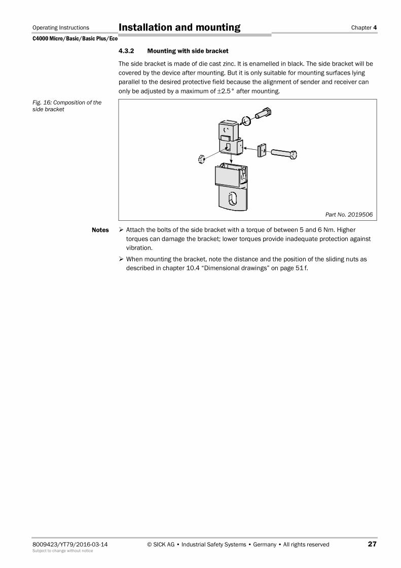
4.3.2 Mounting with side bracket
The side bracket is made of die cast zinc. It is enamelled in black. The side bracket will becovered by the device after mounting. But it is only suitable for mounting surfaces lyingparallel to the desired protective field because the alignment of sender and receiver canonly be adjusted by a maximum of °2.5° after mounting.
⋅ Attach the bolts of the side bracket with a torque of between 5 and 6 Nm. Highertorques can damage the bracket; lower torques provide inadequate protection againstvibration.
⋅ When mounting the bracket, note the distance and the position of the sliding nuts asdescribed in chapter 10.4 “Dimensional drawings” on page 51 f.
Fig. 16: Composition of theside bracket
Notes
Part No. 2019506

Chapter 4 Operating Instructions
C4000 Micro/Basic/Basic Plus/Eco
28 © SICK AG • Industrial Safety Systems • Germany • All rights reserved 8009423/YT79/2016-03-14Subject to change without notice
Installation and mounting
⋅ When mounting the side bracket make sure that the bolts marked 0 and 1 remainaccessible, allowing you later to adjust and lock the light curtain in position.
⋅ If you wish to use the additional front screen (see “Additional front screen (weld sparkguard)” on page 61), make sure that the curved side of the device remains accessibleafter mounting.
Fig. 17: Mounting the C4000with side bracket
Notes
Sliding nut
Sliding nut
1
0

Operating Instructions Chapter 5
C4000 Micro/Basic/Basic Plus/Eco
8009423/YT79/2016-03-14 © SICK AG • Industrial Safety Systems • Germany • All rights reserved 29Subject to change without notice
Electrical installation
5 Electrical installation
Switch the entire machine/system off line!
The machine/system could unintentionally start up while you are connecting the devices.
⋅ Ensure that the entire machine/system is disconnected during the electrical installa-tion.
Ensure that downstream contactors are monitored!
Downstream contactors must be positively guided and monitored (see section 5.4 “Exter-nal device monitoring (EDM)” on page 33)!
Connect OSSD1 and OSSD2 separately!
You are not allowed to connect OSSD1 and OSSD2 together, otherwise signal safety willnot be ensured.
⋅ Ensure that the machine controller processes the two signals separately.
WARNING

Chapter 5 Operating Instructions
C4000 Micro/Basic/Basic Plus/Eco
30 © SICK AG • Industrial Safety Systems • Germany • All rights reserved 8009423/YT79/2016-03-14Subject to change without notice
Electrical installation
Prevent the formation of a potential difference between the load and the protectivedevice!
⋅ If you connect loads that are not reverse-polarity protected to the OSSDs or the safetyoutputs, you must connect the 0 V connections of these loads and those of the corres-ponding protective device individually and directly to the same 0 V terminal strip. This isthe only way to ensure that, in the event of a defect, there can be no potential diffe-rence between the 0 V connections of the loads and those of the corresponding protec-tive device.
The two outputs are protected against short-circuits to 24 V DC and 0 V. When the lightpath is clear, the signal level on the outputs is HIGH DC (at potential), when the lightbeams are interrupted or there is a device fault the outputs are LOW DC.
The safety light curtain C4000 meets the interference suppression requirements (EMC)for industrial use (interference suppression class A). When used in residential areas itcan cause interference.
To ensure full electromagnetic compatibility (EMC), functional earthing (FE) must beconnected.
The external voltage supply of the device must be capable of buffering brief mains vol-tage failures of 20 ms as specified in EN 60 204-1. Suitable power supplies are availa-ble as accessories from SICK (SICK Power Supply 50 W (Part number 7028789)/SICKPower Supply 95 W (Part number 7028790)).
Notes
OSSD
1Sa
fety
outp
ut1
OSSD
2Sa
fety
outp
ut2
OSSD
1Sa
fety
outp
ut1
OSSD
2Sa
fety
outp
ut2

Operating Instructions Chapter 5
C4000 Micro/Basic/Basic Plus/Eco
8009423/YT79/2016-03-14 © SICK AG • Industrial Safety Systems • Germany • All rights reserved 31Subject to change without notice
Electrical installation
5.1 System connection C4000 Basic (M26 × 6 + FE)
Pin Wire colour ρ Sender θ Receiver
1 Brown 24 V DC input (voltage supply) 24 V DC input (voltage supply)
2 Blue 0 V DC (voltage supply) 0 V DC (voltage supply)
3 Grey Test input:0 V: External test active24 V: External test inactive
OSSD1 (switching output 1)
4 Pink Reserved OSSD2 (switching output 2)
5 Red Reserved Start-up configuration 1
6 Yellow Reserved External device monitoring(EDM) or start-up configuration 2
FE Green Functional earthing Functional earthing
5.2 System connection C4000 Eco (M12 × 4 + FE)
Pin Wire colour ρ Sender θ Receiver
1 Brown 24 V DC input (voltage supply) 24 V DC input (voltage supply)
2 White Reserved OSSD1 (switching output 1)
3 Blue 0 V DC (voltage supply) 0 V DC (voltage supply)
4 Black Reserved OSSD2 (switching output 2)
5 Grey Functional earthing Functional earthing
Fig. 18: Pin assignmentsystem connectionC4000 Basic (M26 × 6 + FE)
Tab. 9: Pin assignmentsystem connectionC4000 Basic (M26 × 6 + FE)
Fig. 19: Pin assignmentsystem connectionC4000 Eco (M12 × 4 + FE)
Tab. 10: Pin assignmentsystem connectionC4000 Eco (M12 × 4 + FE)
4 3 2 1 6 5
2 3 4
FE
5 6 1
FE
ρ θ
ρ θ

Chapter 5 Operating Instructions
C4000 Micro/Basic/Basic Plus/Eco
32 © SICK AG • Industrial Safety Systems • Germany • All rights reserved 8009423/YT79/2016-03-14Subject to change without notice
Electrical installation
5.3 System connection C4000 Micro/Basic Plus(M12 × 7 + FE)
Pin Wire colour ρ Sender θ Receiver
1 White Reserved Reset/restart or start-upconfiguration 2
2 Brown 24 V DC input (voltage supply) 24 V DC input (voltage supply)
3 Green Reserved Start-up configuration 11)
4 Yellow Reserved External device monitoring(EDM)1)
5 Grey Test input:0 V: External test active24 V: External test inactive
OSSD1 (switching output 1)
6 Pink Reserved OSSD2 (switching output 2)
7 Blue 0 V DC (voltage supply) 0 V DC (voltage supply)
FE Screen Functional earthing Functional earthing
1) Pins 3 and 4 of the receiver connection are jumped internally.
Fig. 20: Pin assignmentsystem connectionC4000 Micro/Basic Plus(M12 × 7 + FE)
Tab. 11: Pin assignmentsystem connectionC4000 Micro/Basic Plus(M12 × 7 + FE)
6 FE 5 4 1 FE 7 6
2 3 4 57 1 2 3
ρ θ

Operating Instructions Chapter 5
C4000 Micro/Basic/Basic Plus/Eco
8009423/YT79/2016-03-14 © SICK AG • Industrial Safety Systems • Germany • All rights reserved 33Subject to change without notice
Electrical installation
5.4 External device monitoring (EDM)The EDM checks if the contactors actually de-energise when the protective deviceresponds. If, after an attempted reset, the EDM does not detect a response from theswitched device within 300 ms, the EDM will deactivate the OSSD switching outputs again.
You must implement the external device monitoring electrically by the positive closingaction of both N/C contacts (k1, k2) when the contact elements (K1, K2) reach their de-energised position after the protective device has responded. 24 V is then applied at theinput of the EDM. If 24 V is not present after the response of the protective device, thenone of the contact elements is faulty and the external device monitoring prevents themachine starting up again.
If the contact elements to be monitored are connected to the external device monitoring(EDM) input, then the safety light curtain activates external device monitoring during thenext start-up and saves this configuration in the device.
You can again deactivate the external device monitoring at a later time by using thestart-up configuration (see section 7.4 “Start-up configuration” on page 40). In thiscase, pin 6 (C4000 Basic) and pin 4 (C4000 Micro/Basic Plus), respectively, must notbe connected to 24 V.
Fig. 21: Connecting thecontact elements to the EDM
Notes
24 V DCEDM
OSSD1k1k2
K2
K1
ρ θ
OSSD2 0 V DC

Chapter 5 Operating Instructions
C4000 Micro/Basic/Basic Plus/Eco
34 © SICK AG • Industrial Safety Systems • Germany • All rights reserved 8009423/YT79/2016-03-14Subject to change without notice
Electrical installation
5.5 Reset buttonWhen using C4000 Micro or C4000 Basic (see section 3.4.1 “Restart interlock” on page14), the operator must press the reset button prior to restart.
If you use the C4000 Micro/Basic without restart interlock, then you must implement therestart interlock externally, i.e. on the machine.
Select the correct installation site for the reset button!
Install the reset button outside the hazardous area such that it cannot be operated frominside the hazardous area. When operating the reset button, the operator must have fullvisual command of the hazardous area.
You must activate the restart interlock function, otherwise the reset button remainswithout function during operation. (See chapter 7.2 “Activating the restart interlock” onpage 40.)
5.6 Test input (sender test)
The sender test is performed when 0 V is present at the test input.
Note
WARNING
Fig. 22: Connectionof the reset buttonon the C4000Micro/Basic
Note
Fig. 23: Connection of thesender test button
Pin 1Reset button
ρ
24 V DC
C4000 Basic: Pin 3C4000 Micro: Pin 5
Sender test control, e.g.using button
ρ θ
θ
24 V DC

Operating Instructions Chapter 5
C4000 Micro/Basic/Basic Plus/Eco
8009423/YT79/2016-03-14 © SICK AG • Industrial Safety Systems • Germany • All rights reserved 35Subject to change without notice
Electrical installation
5.7 Switching examplesPlease observe the respective operating instructions of the integrated devices!
5.7.1 C4000 Basic on UE48-20S/UE48-30S with restart interlock and EDM
The C4000 Basic light curtain can be integrated in the switching amplifiers UE48-20S orUE48-30S. Operation is carried out with restart lock and EDM.
Mode of operation:
If the light path is not interrupted, the outputs OSSD1 and OSSD2 are energised. Thesystem is ready to switch on when K1 and K2 are in the de-energised position. Pressingthe button S1 switches on the UE48 switching amplifier. The contacts 13-14 and 23-24 ofthe UE48 activate the contact elements K1 and K2.
If the light path is interrupted, the outputs OSSD1 and OSSD2 are de-energised. Thisswitches off the UE48 and deactivates K1, K2.
Possible fault sources:
Cross and short-circuiting of the outputs OSSD1 and OSSD2 are detected and lead to alock-out. Malfunctions of the contact elements K1 and K2 are detected; the switch-offfunction remains active.
Note
Fig. 24: Switching examplefor C4000 Basic onUE48-20S
Chapter 5 Operating Instructions
C4000 Micro/Basic/Basic Plus/Eco
36 © SICK AG • Industrial Safety Systems • Germany • All rights reserved 8009423/YT79/2016-03-14Subject to change without notice
Electrical installation
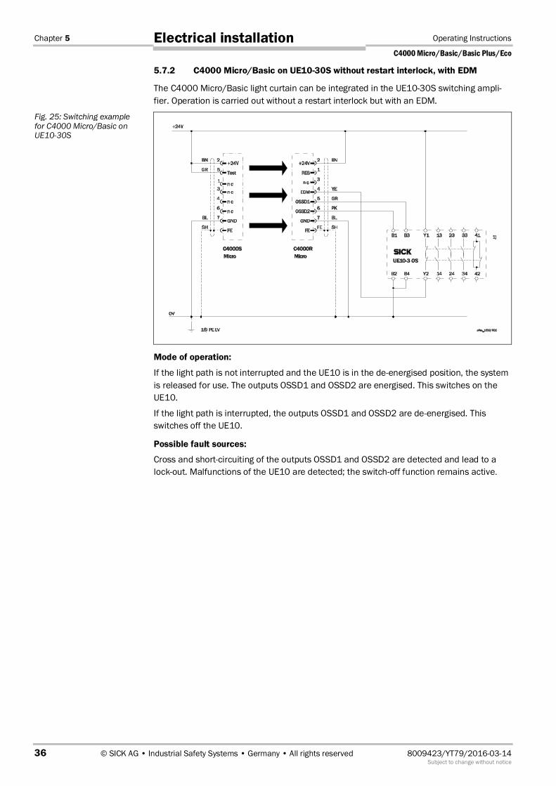
5.7.2 C4000 Micro/Basic on UE10-30S without restart interlock, with EDM
The C4000 Micro/Basic light curtain can be integrated in the UE10-30S switching ampli-fier. Operation is carried out without a restart interlock but with an EDM.
Mode of operation:
If the light path is not interrupted and the UE10 is in the de-energised position, the systemis released for use. The outputs OSSD1 and OSSD2 are energised. This switches on theUE10.
If the light path is interrupted, the outputs OSSD1 and OSSD2 are de-energised. Thisswitches off the UE10.
Possible fault sources:
Cross and short-circuiting of the outputs OSSD1 and OSSD2 are detected and lead to alock-out. Malfunctions of the UE10 are detected; the switch-off function remains active.
Fig. 25: Switching examplefor C4000 Micro/Basic onUE10-30S

Operating Instructions Chapter 6
C4000 Micro/Basic/Basic Plus/Eco
8009423/YT79/2016-03-14 © SICK AG • Industrial Safety Systems • Germany • All rights reserved 37Subject to change without notice
Commissioning
6 Commissioning
Commissioning requires a thorough check by qualified safety personnel!
Before you operate a system protected by the safety light curtain C4000 for the first time,make sure that the system is first checked and approved by qualified safety personnel.Please read the notes in chapter “On safety” on page 8.
6.1 Display sequence during start-upAfter the system is activated, sender and receiver go through a power-up cycle.The 7-segment display indicates the device status during the power-up cycle.
The display values have the following meaning:
Display Meaning
, , , ,, , ,
Testing the 7-segment display. All segments are activatedsequentially.
γ Approx. 0.5 s. Only for systems with a resolution of 14 mm and ascanning range of 1–5 m: Operation with large protective field width
τ Approx. 0.5 s. Uncoded operation. This display is due to reasons ofcompatibility to other C4000 systems.
∩ Approx. 1 s. Device waits for start-up configuration (see section 7.4“Start-up configuration” on page 40).
/, 0 or 1 Receivers only: Receiver-sender alignment incorrect (see “Aligningsender and receiver” below).
Other display Device error. See “Fault diagnosis” on page 43.
6.2 Aligning sender and receiverAfter the light curtain has been mounted and connected, the sender and receiver must bealigned precisely in relation to each other.
How to align sender and receiver in relation to each other:
Secure the plant/system. No dangerous movement possible!
Make sure that the dangerous state of the machine is (and remains) switched off! Duringthe alignment process, the outputs of the safety light curtain are not allowed to have anyeffect on the machine.
⋅ Loosen the clamping bolts which hold the light curtain in place.
⋅ Switch on the power supply to the light curtain.
⋅ Watch the alignment information on the 7-segment display of the receiver (see Tab. 13).Correct the alignment of the sender and receiver, until the 7-segment display goes off.
⋅ Using the clamping bolts, fix the light curtain in place.
⋅ Switch the power supply off and then back on again and check via the 7-segmentdisplay whether the alignment is correct after tightening the clamping bolts (Tab. 13).
WARNING
Tab. 12: Displays shownduring the power-up cycle
WARNING

Chapter 6 Operating Instructions
C4000 Micro/Basic/Basic Plus/Eco
38 © SICK AG • Industrial Safety Systems • Germany • All rights reserved 8009423/YT79/2016-03-14Subject to change without notice
Commissioning
The display values have the following meaning:
Display Meaning
/ The receiver cannot synchronise with the sender; the alignment is verypoor.
0 Some light beams do not hit the receiver.
1 All the light beams hit the receiver, but the alignment is still slightly off.
No display The alignment is now true; the devices must be locked in this position.
If the optimum alignment (= no display) persists for longer than 2 minutes without thelight beam being interrupted, the system automatically deactivates the alignment mode.
If you wish to read just the alignment later, switch the power supply of the C4000 offand back on again.
6.3 Test notes
6.3.1 Tests before the first commissioning
Check the protective device as described below and in accordance with the applicablestandards and regulations.
⋅ Check the effectiveness of the protective device mounted to the machine, using allselectable operating modes as specified in the checklist in the annex (see 12.2 onpage 66).
⋅ Make sure that the operating personnel of the machine protected by the safety lightcurtain are correctly instructed by qualified safety personnel before being allowed tooperate the machine. Instructing the operating personnel is the responsibility of themachine owner.
⋅ Annex 12.2 of this document shows a checklist for review by the manufacturer andOEM. Use this checklist as a reference before commissioning the system for the firsttime.
6.3.2 Regular inspection of the protective device by qualified safety personnel
⋅ Check the system, following the inspection intervals specified in the national rules andregulations. This procedure ensures that any changes on the machine or manipulationsof the protective device are detected before use/re-use.
⋅ If any modifications have been made to the machine or the protective device, or if thesafety light curtain has been changed or repaired, the system must be checked again asspecified in the checklist in the annex.
Tab. 13: Display valuesduring the alignment ofsender and receiver
Notes

Operating Instructions Chapter 6
C4000 Micro/Basic/Basic Plus/Eco
8009423/YT79/2016-03-14 © SICK AG • Industrial Safety Systems • Germany • All rights reserved 39Subject to change without notice
Commissioning
6.3.3 Daily functional checks of the protective device
The effectiveness of the protective device must be checked daily by a specialist or byauthorised personnel, using the correct test rod.
Always test along the complete hazardous area to be protected, never solely at the mount-ing position of the light curtain.
How to check the effectiveness and correct function of the safety light curtain:
⋅ Select the correct test rod depending on device resolution.
Do not operate the machine if the green or yellow LED is lit during the test!
If the green or yellow LED lights up during the test even for a short period, work must stopat the machine. In this case the installation of the safety light curtain must be checked byqualified safety personnel (see chapter 4).
⋅ Before inserting the test rod, check …
– if, for the C4000 Micro or C4000 Basic Plus (M12 × 7+ FE) with de-activated internalrestart interlock or the C4000 Basic, the green LED lights up.
– if, for the C4000 Micro with activated internal restart interlock, the yellow LEDflashes (“Reset required”).
If this is not the case, make sure that this condition is reached. The test is otherwisemeaningless.
⋅ Move the test rod slowly through the area to be protected, as shown under 0 in Fig. 26.
⋅ Then, guide the test rod along the edges of the area to be protected as shown under 1
in Fig. 26. This procedure allows you to test if the point-of-operation guard/reaching be-hind protection is functioning correctly (see chapter 4.3 “Steps for mounting the device”on page 24).
⋅ If you use one or more deflector mirrors (e.g. PNS), then also guide the test rod slowlythrough the area to be protected directly in front of the mirrors.
In both tests, the receiver of the C4000 must show the red LED only.
Note
WARNING
Note
Fig. 26: Daily checks of theprotective device 0 1
Chapter 7 Operating Instructions
C4000 Micro/Basic/Basic Plus/Eco
40 © SICK AG • Industrial Safety Systems • Germany • All rights reserved 8009423/YT79/2016-03-14Subject to change without notice
Configuration
7 Configuration
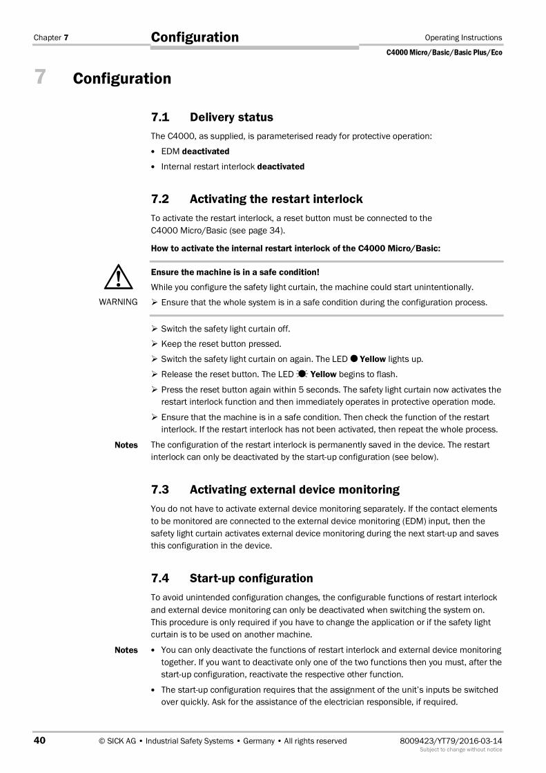
7.1 Delivery statusThe C4000, as supplied, is parameterised ready for protective operation:
EDM deactivated
Internal restart interlock deactivated
7.2 Activating the restart interlockTo activate the restart interlock, a reset button must be connected to theC4000 Micro/Basic (see page 34).
How to activate the internal restart interlock of the C4000 Micro/Basic:
Ensure the machine is in a safe condition!
While you configure the safety light curtain, the machine could start unintentionally.
⋅ Ensure that the whole system is in a safe condition during the configuration process.
⋅ Switch the safety light curtain off.
⋅ Keep the reset button pressed.
⋅ Switch the safety light curtain on again. The LED Ν Yellow lights up.
⋅ Release the reset button. The LED ∏ Yellow begins to flash.
⋅ Press the reset button again within 5 seconds. The safety light curtain now activates therestart interlock function and then immediately operates in protective operation mode.
⋅ Ensure that the machine is in a safe condition. Then check the function of the restartinterlock. If the restart interlock has not been activated, then repeat the whole process.
The configuration of the restart interlock is permanently saved in the device. The restartinterlock can only be deactivated by the start-up configuration (see below).
7.3 Activating external device monitoringYou do not have to activate external device monitoring separately. If the contact elementsto be monitored are connected to the external device monitoring (EDM) input, then thesafety light curtain activates external device monitoring during the next start-up and savesthis configuration in the device.
7.4 Start-up configurationTo avoid unintended configuration changes, the configurable functions of restart interlockand external device monitoring can only be deactivated when switching the system on.This procedure is only required if you have to change the application or if the safety lightcurtain is to be used on another machine.
You can only deactivate the functions of restart interlock and external device monitoringtogether. If you want to deactivate only one of the two functions then you must, after thestart-up configuration, reactivate the respective other function.
The start-up configuration requires that the assignment of the unit’s inputs be switchedover quickly. Ask for the assistance of the electrician responsible, if required.
WARNING
Notes
Notes

Operating Instructions Chapter 7
C4000 Micro/Basic/Basic Plus/Eco
8009423/YT79/2016-03-14 © SICK AG • Industrial Safety Systems • Germany • All rights reserved 41Subject to change without notice
Configuration
How to deactivate the restart interlock and external device monitoring:
Ensure the machine is in a safe condition!
While you configure the safety light curtain, the machine could start unintentionally.
⋅ Ensure that the whole system is in a safe condition during the configuration process.
Only authorised personnel must perform the start-up configuration.
⋅ Switch the safety light curtain off.
⋅ If an EDM is connected, disconnect the wiring.
⋅ Connect the start-up configuration 1 and start-up configuration 2 inputs.
⋅ Switch the safety light curtain on. The 7-segment display shows ∩ as confirmation. 0
⋅ Within the next 2 seconds, connect the start-up configuration 1 and start-up configura-tion 2 inputs with 24 V. The 7-segment display shows ⊃ as confirmation. 1
⋅ Disconnect the inputs start-up configuration 1 and Switch-on configuration 2 from 24 Vwithin the next 2 seconds. The 7-segment display shows ∩ as confirmation. 2
⋅ Once again, connect the start-up configuration 1 and start-up configuration 2 inputswith 24 V, within the next 2 seconds. The 7-segment display shows ⊃ as confirmationfor 2 seconds. 3
⋅ Disconnect the inputs start-up configuration 1 and start-up configuration 2 from 24 Vwithin the next 2 seconds. After successful completion of the start-up configuration, the7-segment display shows 4. 4
⋅ Switch the safety light curtain off.
⋅ Remove the connecting cables of the external device monitoring, if you do not want touse this function any more.
⋅ Switch the safety light curtain on again. External device monitoring and restart interlockare now deactivated.
⋅ Verify the effectiveness of the protective device as described in chapter 6.3 “Testnotes” on page 38.
WARNING
Note
Fig. 27: Time sequencediagram of the start-upconfiguration(n. c. = not connected)
Start-upconfigu-ration 1
24 V DC
24 V DC
Start-upconfigu-ration 2
n. c.
n. c.
2 s 2 s 2 s 2 s
0 1 2 3 4

Chapter 8 Operating Instructions
C4000 Micro/Basic/Basic Plus/Eco
42 © SICK AG • Industrial Safety Systems • Germany • All rights reserved 8009423/YT79/2016-03-14Subject to change without notice
Care and maintenance
8 Care and maintenanceThe safety light curtain C4000 is maintenance-free. The front screen of the safety lightcurtain C4000 and any additional front screen(s) (see “Additional front screen (weld sparkguard)” on page 61) should be cleaned at regular intervals and when dirty.
⋅ Do not use aggressive cleaning agents.
⋅ Do not use abrasive cleaning agents.
Static charges cause dust particles to be attracted to the front screen. You can preventthis effect by using the antistatic plastic cleaner (SICK part number 5600006) and theSICK lens cloth (part number 4003353).
How to clean the front screen and/or the additional front screen (optional extra):
⋅ Use a clean and soft brush to remove dust from the front screen.
⋅ Then wipe the front screen with a clean and damp cloth.
⋅ After cleaning, check the position of sender and receiver to make sure that the protec-tive device cannot be bypassed (reaching above, below or stepping behind).
⋅ Verify the effectiveness of the protective device as described in chapter 6.3 “Testnotes” on page 38.
Note
Note

Operating Instructions Chapter 9
C4000 Micro/Basic/Basic Plus/Eco
8009423/YT79/2016-03-14 © SICK AG • Industrial Safety Systems • Germany • All rights reserved 43Subject to change without notice
Fault diagnosis
9 Fault diagnosisThis chapter describes how to identify and remedy errors and malfunctions during theoperation of the safety light curtain.
9.1 What to do in case of faults
Cease operation if the cause of the malfunction has not been clearly identified!
Stop the machine if you cannot clearly identify or allocate the error and if you cannot safelyremedy the malfunction.
The system state “Lock-out”
In case of certain faults or an erroneous configuration, the system can go into the “Lock-out” state. The 7-segment display on the safety light curtain then indicates δ, ε or κ. Toplace the device back in operation:
⋅ Rectify the cause of the fault as per Tab. 15.
⋅ Switch the power supply for the C4000 off and on again (e.g. by unplugging the systemplug and reinserting it).
9.2 SICK SupportIf you cannot remedy an error with the help of the information provided in this chapter,please contact your local SICK representative.
9.3 Error displays of the diagnostics LEDsThis chapter explains the meaning of the error displays of the LEDs and how to respond.Please refer to the description in chapter “Status indicators” on page 17.
Display Possible cause Remedying the error
Ν Orange LED of receiverlights up
Weak signal ⋅ Check the alignment of senderand receiver.
⋅ Check the front screen (dirt)and clean, if necessary.
∏ Yellow LED of receiverflashes
Reset required ⋅ Press the reset button.
ν Yellow LED of senderfails to light up
ν Red andν Green
Neither the rednor the greenreceiver LEDlights up
No operatingvoltage, or voltagetoo low
⋅ Check the voltage supply andactivate, if necessary.
WARNING
Tab. 14: Error displays of theLEDs

Chapter 9 Operating Instructions
C4000 Micro/Basic/Basic Plus/Eco
44 © SICK AG • Industrial Safety Systems • Germany • All rights reserved 8009423/YT79/2016-03-14Subject to change without notice
Fault diagnosis
9.4 Error displays of the 7-segment displayThis chapter explains the meaning of the error displays of the 7-segment display and howto respond to the messages. Please refer to section “ Status indicators” on page 17 for adescription of the 7-segment display.
Display Possible cause Remedying the error
/, 0 or1
Inadequate alignment ⋅ Re-align sender and receiver (see page 37).
The display extinguishes 2 minutes after thesystem has been correctly aligned.
7
or∋
EDM error ⋅ Check the contacts and their wiring, eliminateany wiring errors, if necessary.
⋅ If ∋ is displayed, switch the device off and backon again.
8 Reset button fault ⋅ Check the reset button for correct function. Thebutton may be defective or stuck.
⋅ Check the wiring of the reset button/for anyshort-circuit to 24 V.
δ System error ⋅ Replace the unit (receiver or sender).
ε?0 Overcurrent atswitching output 1
⋅ Check the contactor. Replace, if necessary.
⋅ Check the wiring for short-circuit to 0 V.
ε?1 Short-circuit atswitching output 1
⋅ Check the wiring for short-circuit to 24 V.
ε?2 Short-circuit atswitching output 1
⋅ Check the wiring for short-circuit to 0 V.
ε?3 Overcurrent atswitching output 2
⋅ Check the contactor. Replace, if necessary.
⋅ Check the wiring for short-circuit to 0 V.
ε?4 Short-circuit atswitching output 2
⋅ Check the wiring for short-circuit to 24 V.
ε?5 Short-circuit atswitching output 2
⋅ Check the wiring for short-circuit to 0 V.
ε?6 Short-circuit betweenswitching output1 and 2
⋅ Check the wiring and rectify the error.
κ?1 Invalid configuration ofthe EDM
⋅ Verify that the machine-side EDM is connectedcorrectly.
κ?2 External senderdetected
⋅ Check the distance from reflective surfaces(page 22) or from other light curtains.
⋅ Swap sender and receiver (inversion of the beamdirection) or fit non-reflective partition walls.
κ?5 Start-up configurationnot successfullycompleted
⋅ Repeat the start-up configuration
κ?8 Supply voltage too low ⋅ Check the supply voltage and the power supply.If necessary, replace defective components.
Tab. 15: Error displays of the7-segment display

Operating Instructions Chapter 10
C4000 Micro/Basic/Basic Plus/Eco
8009423/YT79/2016-03-14 © SICK AG • Industrial Safety Systems • Germany • All rights reserved 45Subject to change without notice
Technical specifications
10 Technical specifications
10.1 Data sheetMinimum Typical Maximum
General system data
Type Type 4 (IEC 61 496-1)
Safety integrity level2) SIL3 (IEC 61 508)
SIL claim limit2) SILCL3 (EN 62 061)
Category Category 4 (EN ISO 13 849-1)
Performance Level2) PL e (EN ISO 13 849-1)
PFHd (mean probability of adangerous failure per hour)
15 × 10–9
TM (mission time) 20 years (EN ISO 13 849-1)
Protective field height, dependingon type
C4000 Basic/Basic Plus/Eco 300 mm to 1800 mm
C4000 Micro 150 mm to 1200 mm
Resolution, depending on type 14 mm and 30 mmProtective field width
Resolution 14 mm 0 m 5 mResolution 30 mm 0 m 6 m
Protection class III (EN 61 140)Enclosure rating IP 65 (IEC 60 529)Supply voltage UV at device3) 19.2 V 24 V 28.8 VResidual ripple4) (SELV) ° 10 %Synchronisation Optical, without separate synchronisationPower-up delay of sender andreceiver before ready
8 s
2) For detailed information on the exact design of your machine/system, please contact your local SICKrepresentative.
3) The external voltage supply must be capable of buffering brief mains failures of 20 ms as specified inEN 60 204-1. Suitable power supplies are available as accessories from SICK (SICK Power Supply 50 W (Partnumber 7028789)/SICK Power Supply 95 W (Part number 7028790)).
4) Within the limits of UV.
Tab. 16: Technical dataC4000 Basic/Micro/Eco
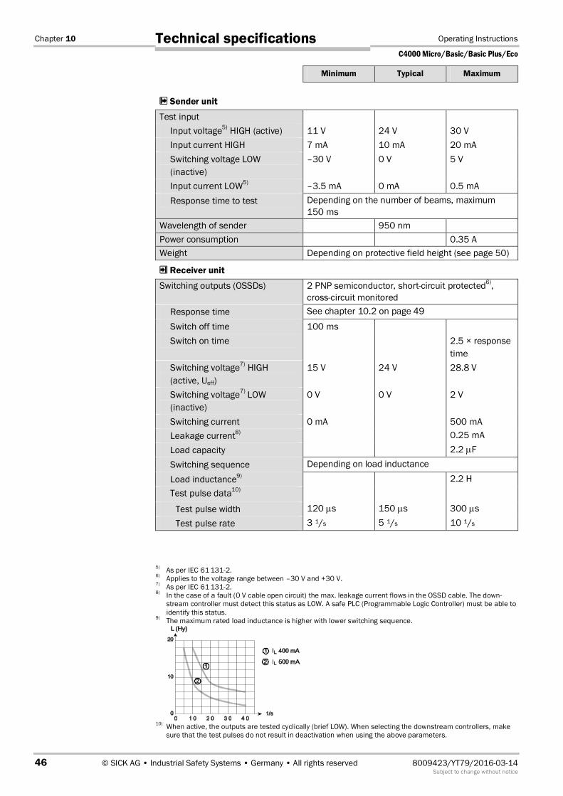
Chapter 10 Operating Instructions
C4000 Micro/Basic/Basic Plus/Eco
46 © SICK AG • Industrial Safety Systems • Germany • All rights reserved 8009423/YT79/2016-03-14Subject to change without notice
Technical specifications
Minimum Typical Maximum
ρ Sender unit
Test inputInput voltage5) HIGH (active) 11 V 24 V 30 VInput current HIGH 7 mA 10 mA 20 mASwitching voltage LOW(inactive)
–30 V 0 V 5 V
Input current LOW5) –3.5 mA 0 mA 0.5 mAResponse time to test Depending on the number of beams, maximum
150 msWavelength of sender 950 nmPower consumption 0.35 AWeight Depending on protective field height (see page 50)
θ Receiver unit
Switching outputs (OSSDs) 2 PNP semiconductor, short-circuit protected6),cross-circuit monitored
Response time See chapter 10.2 on page 49
Switch off time 100 msSwitch on time 2.5 × response
timeSwitching voltage7) HIGH(active, Ueff)
15 V 24 V 28.8 V
Switching voltage7) LOW(inactive)
0 V 0 V 2 V
Switching current 0 mA 500 mALeakage current8) 0.25 mALoad capacity 2.2 λF
Switching sequence Depending on load inductance
Load inductance9) 2.2 HTest pulse data10)
Test pulse width 120 λs 150 λs 300 λsTest pulse rate 3 ¹/s 5 ¹/s 10 ¹/s
5) As per IEC 61 131-2.6) Applies to the voltage range between –30 V and +30 V.7) As per IEC 61 131-2.8) In the case of a fault (0 V cable open circuit) the max. leakage current flows in the OSSD cable. The down-
stream controller must detect this status as LOW. A safe PLC (Programmable Logic Controller) must be able toidentify this status.
9) The maximum rated load inductance is higher with lower switching sequence.
10) When active, the outputs are tested cyclically (brief LOW). When selecting the downstream controllers, makesure that the test pulses do not result in deactivation when using the above parameters.

Operating Instructions Chapter 10
C4000 Micro/Basic/Basic Plus/Eco
8009423/YT79/2016-03-14 © SICK AG • Industrial Safety Systems • Germany • All rights reserved 47Subject to change without notice
Technical specifications
Minimum Typical Maximum
Permissible cable resistanceBetween device and load11) 2.5 ΩSupply lead 1 Ω
Power consumption 0.45 A + max.1 A OSSD load
External device monitoring (EDM)input
Input voltage12) HIGH (inactive) 11 V 24 V 30 VInput current HIGH 6 mA 10 mA 20 mAInput voltage12) LOW (active) –30 V 0 V 5 VInput current LOW –2.5 mA 0 mA 0.5 mA
ContactorsPermissible dropout time 300 msPermissible pick-up time 300 ms
Control switch input(reset button)
Input voltage12) HIGH (active) 11 V 24 V 30 VInput current HIGH 6 mA 10 mA 20 mAInput voltage12) LOW (inactive) –30 V 0 V 5 VInput current LOW –2.5 mA 0 mA 0.5 mAOperation time control switchinput
110 ms
Weight Depending on protective field height (see page 50)
11) Make sure to limit the individual cable resistance to the downstream controller to this value to ensure that across-circuit between the outputs is safely detected. (Also note EN 60 204 Electrical Machine Equipment,Part 1: General Requirements.)
12) As per IEC 61 131-2.

Chapter 10 Operating Instructions
C4000 Micro/Basic/Basic Plus/Eco
48 © SICK AG • Industrial Safety Systems • Germany • All rights reserved 8009423/YT79/2016-03-14Subject to change without notice
Technical specifications
Minimum Typical Maximum
Operating data
Connection
C4000 Basic M26 × 6 + FEC4000 Eco M12 × 4 + FEC4000 Micro/Basic Plus M12 × 7 + FE
Line length and cross section13)
C4000 Basic 50 m/0.75 mm²C4000 Eco 15 m/0.25 mm2
C4000 Micro/Basic Plus14) 15 m/0.25 mm²Ambient operating temperature 0°C +55°CAir humidity (non-dewing) 15 % 95 %Storage temperature –25°C +70°CHousing cross-section
C4000 Basic/Basic Plus/Eco 40 mm × 48 mm
C4000 Micro 28.5 mm × 33.5 mm
Rigidity 5 g, 10–55 Hz acc. to EN 60 068-2-6Shock resistance 10 g, 16 ms acc. to EN 60 068-2-27
13) Dependent on loading, power supply. The technical specifications must be observed.14) If connection cables with large wire cross-section are used, the distance between the devices may be
extended. Possible cable lengths for M12 connectors (0.25 mm2) when extended with a larger wire cross-section area cable after x metres:
1 = Remaining cable length after extension in metres 3 = Wire cross-section area of 2.5 mm2
2 = Cable length in metres with a wire cross-section area of 0.25 mm2
4 = Wire cross-section area of 1.0 mm2
5 = Wire cross-section area of 0.5 mm2
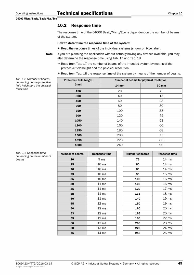
Operating Instructions Chapter 10
C4000 Micro/Basic/Basic Plus/Eco
8009423/YT79/2016-03-14 © SICK AG • Industrial Safety Systems • Germany • All rights reserved 49Subject to change without notice
Technical specifications
10.2 Response timeThe response time of the C4000 Basic/Micro/Eco is dependent on the number of beamsof the system.
How to determine the response time of the system:
⋅ Read the response times of the individual systems (shown on type label).
If you are planning the application without actually having any devices available, you mayalso determine the response time using Tab. 17 and Tab. 18:
⋅ Read from Tab. 17 the number of beams of the intended system by means of theprotective field height and the physical resolution.
⋅ Read from Tab. 18 the response time of the system by means of the number of beams.
Number of beams for physical resolutionProtective field height[mm] 14 mm 30 mm
150 20 8300 40 15450 60 23600 80 30750 100 38900 120 45
1050 140 531200 160 601350 180 681500 200 751650 220 831800 240 90
Number of beams Response time Number of beams Response time
10 9 ms 75 14 ms15 10 ms 80 14 ms20 10 ms 83 14 ms23 10 ms 90 15 ms25 10 ms 100 16 ms30 11 ms 105 16 ms35 11 ms 120 17 ms38 11 ms 135 18 ms40 11 ms 140 19 ms45 12 ms 150 19 ms50 12 ms 160 20 ms53 12 ms 165 20 ms55 12 ms 180 22 ms60 13 ms 200 23 ms68 13 ms 220 24 ms75 14 ms 240 26 ms
Note
Tab. 17: Number of beamsdepending on the protectivefield height and the physicalresolution
Tab. 18: Response timedepending on the number ofbeams

Chapter 10 Operating Instructions
C4000 Micro/Basic/Basic Plus/Eco
50 © SICK AG • Industrial Safety Systems • Germany • All rights reserved 8009423/YT79/2016-03-14Subject to change without notice
Technical specifications
10.3 Table of weights
10.3.1 C4000 Basic/Micro/Eco
Weight [g] C4000 Basic/Eco Weight [g] C4000 MicroProtective fieldheight [mm] ρ Sender θ Receiver ρ Sender θ Receiver
150 — — 275 290
300 820 850 370 385
450 1100 1130 510 525
600 1390 1420 650 665
750 1670 1700 795 810
900 1960 1990 940 955
1050 2250 2280 1085 1100
1200 2530 2560 1235 1250
1350 2820 2850 — —
1500 3110 3140 — —
1650 3390 3420 — —
1800 3680 3710 — —
10.3.2 Deflector mirrors PNS75 and PNS125
Weight [g]Mirror height[mm] PNS75 PNS125
340 1035 1580
490 1435 2190
640 1850 2820
790 2270 3450
940 2680 4080
1090 3095 4710
1240 3510 5345
1390 3925 5980
1540 4340 6610
1690 4755 7240
1840 5170 7870
Tab. 19: Weight of senderand receiver
Tab. 20: Weight of thedeflector mirrors PNS75and PNS125

Operating Instructions Chapter 10
C4000 Micro/Basic/Basic Plus/Eco
8009423/YT79/2016-03-14 © SICK AG • Industrial Safety Systems • Germany • All rights reserved 51Subject to change without notice
Technical specifications
10.4 Dimensional drawings
10.4.1 C4000 Basic/Basic Plus/Eco
Protective field heightS [mm]
DimensionL1 [mm]
DimensionL2 [mm]
DimensionA [mm]
300 372 417 224450 523 568 374600 674 718 524750 824 869 674900 975 1020 824
1050 1125 1170 9741200 1274 1319 11241350 1426 1471 12741500 1577 1622 14241650 1727 1772 15741800 1878 1923 1724
Fig. 28: Dimensional drawingC4000 Basic/Basic Plus/Ecosender (mm)Receiver mirror image
Tab. 21: Dimensions depend-ent on the protective fieldheight, C4000 Basic/Ecosender
48
10
DIN 43 651 plug (M26 × 6 + FE)
4020
L1
L2
S
66
47,822,4
A
Sliding nut groovefor side mounting
146
10,5
2,2
1 3,5
Straight cable socketM26 × 6 + FE with
crimp contactsap
prox
.100
(con
nect
orra
nge)
76,5
appr
ox.1
30(c
onne
ctor
rang
e)
100
73
Angled cable socketM26 × 6 + FE with
screw contactsap
prox
.90
(con
nect
orra
nge)
57
appr
ox.5
6(c
onne
ctor
rang
e)
39
Cable sockets M12 × 7 + screenCable sockets M12 × 4 + screen
10 45°
7

Chapter 10 Operating Instructions
C4000 Micro/Basic/Basic Plus/Eco
52 © SICK AG • Industrial Safety Systems • Germany • All rights reserved 8009423/YT79/2016-03-14Subject to change without notice
Technical specifications
10.4.2 C4000 Micro
Protective field heightS [mm]
DimensionL1 [mm]
DimensionL2 [mm]
DimensionA [mm]
150 246 276 106300 364 394 224450 515 545 374600 666 696 524750 816 846 674900 967 997 824
1050 1117 1147 9741200 1266 1296 1124
Fig. 29: Dimensional drawingC4000 Micro sender (mm)Receiver mirror image
Tab. 22: Dimensions depend-ent on the protective fieldheight, C4000 Micro sender
43.8
9
Hirschmann plug M12 × 7 + FE
28.516.5
L1L2
S
66
33.519.3
A
Sliding nut groovefor side mounting
146
10.5
2.2
1 3.5
Cable sockets M12 × 7 + screen
appr
ox.9
0(c
onne
ctor
rang
e)
57
appr
ox.5
6(c
onne
ctor
rang
e)
39
21
7
10 45°

Operating Instructions Chapter 10
C4000 Micro/Basic/Basic Plus/Eco
8009423/YT79/2016-03-14 © SICK AG • Industrial Safety Systems • Germany • All rights reserved 53Subject to change without notice
Technical specifications
10.4.3 Swivel mount bracket
Swivel mount for … DimensionD [mm]
DimensionL1 [mm]
DimensionL2 [mm]
DimensionL3 [mm]
C4000 Basic/Eco,PNS75 and PNS125
30.6 44.4 75 42
C4000 Micro 24 34.3 62 36
10.4.4 Side bracket
Fig. 30: Dimensional drawingswivel mount bracket (mm)
Tab. 23: Dimensions of theswivel mount bracketdependent on the housingprofile
Fig. 31: Dimensional drawing,side bracket (mm)
L3
L2
8
3.8 L1
D
4413
Part No. 2019506
19
50
9
5.5
34.5
15
18
6
Part No. 2019659 (for C4000 Basic/Eco anddeflector mirror PNS)
Part No. 2019649 (for C4000 Micro)
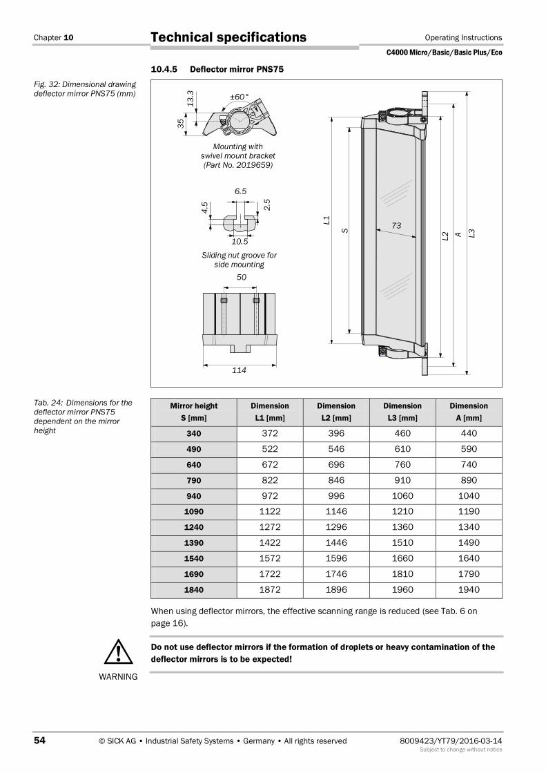
Chapter 10 Operating Instructions
C4000 Micro/Basic/Basic Plus/Eco
54 © SICK AG • Industrial Safety Systems • Germany • All rights reserved 8009423/YT79/2016-03-14Subject to change without notice
Technical specifications
10.4.5 Deflector mirror PNS75
Mirror heightS [mm]
DimensionL1 [mm]
DimensionL2 [mm]
DimensionL3 [mm]
DimensionA [mm]
340 372 396 460 440
490 522 546 610 590
640 672 696 760 740
790 822 846 910 890
940 972 996 1060 1040
1090 1122 1146 1210 1190
1240 1272 1296 1360 1340
1390 1422 1446 1510 1490
1540 1572 1596 1660 1640
1690 1722 1746 1810 1790
1840 1872 1896 1960 1940
When using deflector mirrors, the effective scanning range is reduced (see Tab. 6 onpage 16).
Do not use deflector mirrors if the formation of droplets or heavy contamination of thedeflector mirrors is to be expected!
Fig. 32: Dimensional drawingdeflector mirror PNS75 (mm)
Tab. 24: Dimensions for thedeflector mirror PNS75dependent on the mirrorheight
WARNING
10.5
50
S
3513
.3 ±60°
2.5
114
6.5
L1
L2 A L3
4.5
Sliding nut groove forside mounting
Mounting withswivel mount bracket(Part No. 2019659)
73

Operating Instructions Chapter 10
C4000 Micro/Basic/Basic Plus/Eco
8009423/YT79/2016-03-14 © SICK AG • Industrial Safety Systems • Germany • All rights reserved 55Subject to change without notice
Technical specifications
10.4.6 Deflector mirror PNS125
Mirror heightS [mm]
DimensionL1 [mm]
DimensionL2 [mm]
DimensionL3 [mm]
DimensionA [mm]
340 372 396 460 440
490 522 546 610 590
640 672 696 760 740
790 822 846 910 890
940 972 996 1060 1040
1090 1122 1146 1210 1190
1240 1272 1296 1360 1340
1390 1422 1446 1510 1490
1540 1572 1596 1660 1640
1690 1722 1746 1810 1790
1840 1872 1896 1960 1940
When using deflector mirrors, the effective scanning range is reduced (see Tab. 6 onpage 16).
Do not use deflector mirrors if the formation of droplets or heavy contamination of thedeflector mirrors is to be expected!
Fig. 33: Dimensional drawingdeflector mirror PNS125(mm)
Tab. 25: Dimensions for thedeflector mirror PNS125dependent on the mirrorheight
WARNING
10.5
50
S
3513
.3 ±60°
2.5
164
6.5
L1
L2 A L3
4.5
Sliding nut groove forside mounting
Mounting withswivel mount bracket(Part No. 2019659)
50
50
123

Chapter 11 Operating Instructions
C4000 Micro/Basic/Basic Plus/Eco
56 © SICK AG • Industrial Safety Systems • Germany • All rights reserved 8009423/YT79/2016-03-14Subject to change without notice
Ordering information
11 Ordering information
11.1 Delivery
Delivery, sender
sender unit
4 sliding nuts for side bracket(C4000 Basic, C4000 Basic Plus, C4000 Eco only)
Delivery, receiver
receiver unit
4 sliding nuts for side bracket
test rod with diameter corresponding to the physical resolution of the safety light curtain
information label “ Important Information”
operating instructions on CD-ROM
information label “Operator’s notes”
Delivery, deflector mirror
deflector mirror
2 swivel mount brackets

Operating Instructions Chapter 11
C4000 Micro/Basic/Basic Plus/Eco
8009423/YT79/2016-03-14 © SICK AG • Industrial Safety Systems • Germany • All rights reserved 57Subject to change without notice
Ordering information
11.2 C4000 Basic (M26 × 6 + FE)Part numbers for resolution and scanning range
14 mm 14 mm 30 mm
Protective fieldheight[mm]
0–2.5 m 1–5 m 0–6 m
300
ρ 1022195(C40S-0301AA030)
θ 1022196(C40E-0301AH030)
ρ 1022195(C40S-0301AA030)
θ 1022240(C40E-0301BH030)
ρ 1022218(C40S-0303AA030)
θ 1022219(C40E-0303AH030)
450
ρ 1022198(C40S-0401AA030)
θ 1022199(C40E-0401AH030)
ρ 1022198(C40S-0401AA030)
θ 1022241(C40E-0401BH030)
ρ 1022220(C40S-0403AA030)
θ 1022221(C40E-0403AH030)
600
ρ 1022200(C40S-0601AA030)
θ 1022201(C40E-0601AH030)
ρ 1022200(C40S-0601AA030)
θ 1022242(C40E-0601BH030)
ρ 1022222(C40S-0603AA030)
θ 1022223(C40E-0603AH030)
750
ρ 1022202(C40S-0701AA030)
θ 1022203(C40E-0701AH030)
ρ 1022202(C40S-0701AA030)
θ 1022243(C40E-0701BH030)
ρ 1022224(C40S-0703AA030)
θ 1022225(C40E-0703AH030)
900
ρ 1022204(C40S-0901AA030)
θ 1022205(C40E-0901AH030)
ρ 1022204(C40S-0901AA030)
θ 1022244(C40E-0901BH030)
ρ 1022226(C40S-0903AA030)
θ 1022227(C40E-0903AH030)
1050
ρ 1022206(C40S-1001AA030)
θ 1022207(C40E-1001AH030)
ρ 1022206(C40S-1001AA030)
θ 1022245(C40E-1001BH030)
ρ 1022228(C40S-1003AA030)
θ 1022229(C40E-1003AH030)
1200
ρ 1022208(C40S-1201AA030)
θ 1022209(C40E-1201AH030)
ρ 1022208(C40S-1201AA030)
θ 1022246(C40E-1201BH030)
ρ 1022230(C40S-1203AA030)
θ 1022231(C40E-1203AH030)
1350
ρ 1022210(C40S-1301AA030)
θ 1022211(C40E-1301AH030)
ρ 1022210(C40S-1301AA030)
θ 1022247(C40E-1301BH030)
ρ 1022232(C40S-1303AA030)
θ 1022233(C40E-1303AH030)
1500
ρ 1022212(C40S-1501AA030)
θ 1022213(C40E-1501AH030)
ρ 1022212(C40S-1501AA030)
θ 1022248(C40E-1501BH030)
ρ 1022234(C40S-1503AA030)
θ 1022235(C40E-1503AH030)
1650
ρ 1022214(C40S-1601AA030)
θ 1022215(C40E-1601AH030)
ρ 1022214(C40S-1601AA030)
θ 1022249(C40E-1601BH030)
ρ 1022236(C40S-1603AA030)
θ 1022237(C40E-1603AH030)
1800
ρ 1022216(C40S-1801AA030)
θ 1022217(C40E-1801AH030)
ρ 1022216(C40S-1801AA030)
θ 1022250(C40E-1801BH030)
ρ 1022238(C40S-1803AA030)
θ 1022239(C40E-1803AH030)
Tab. 26: Part numbersC4000 Basic (M26 × 6 + FE)

Chapter 11 Operating Instructions
C4000 Micro/Basic/Basic Plus/Eco
58 © SICK AG • Industrial Safety Systems • Germany • All rights reserved 8009423/YT79/2016-03-14Subject to change without notice
Ordering information
11.3 C4000 Eco (M12 × 4 + FE)Part numbers for resolution and scanning range
14 mm 14 mm 30 mm
Protective fieldheight[mm]
0–2,5 m 1–5 m 0–6 m
300
ρ 1027440(C40S-0301AA310)
θ 1027441(C40E-0301AN310)
ρ 1027440(C40S-0301AA310)
θ 1027486(C40E-0301BN310)
ρ 1027464(C40S-0303AA310)
θ 1027465(C40E-0303AN310)
450
ρ 1027442(C40S-0401AA310)
θ 1027443(C40E-0401AN310)
ρ 1027442(C40S-0401AA310)
θ 1027487(C40E-0401BN310)
ρ 1027466(C40S-0403AA310)
θ 1027467(C40E-0403AN310)
600
ρ 1027444(C40S-0601AA310)
θ 1027445(C40E-0601AN310)
ρ 1027444(C40S-0601AA310)
θ 1027488(C40E-0601BN310)
ρ 1027468(C40S-0603AA310)
θ 1027469(C40E-0603AN310)
750
ρ 1027446(C40S-0701AA310)
θ 1027447(C40E-0701AN310)
ρ 1027446(C40S-0701AA310)
θ 1027489(C40E-0701BN310)
ρ 1027470(C40S-0703AA310)
θ 1027471(C40E-0703AN310)
900
ρ 1027448(C40S-0901AA310)
θ 1027449(C40E-0901AN310)
ρ 1027448(C40S-0901AA310)
θ 1027490(C40E-0901BN310)
ρ 1027472(C40S-0903AA310)
θ 1027473(C40E-0903AN310)
1050
ρ 1027450(C40S-1001AA310)
θ 1027451(C40E-1001AN310)
ρ 1027450(C40S-1001AA310)
θ 1027491(C40E-1001BN310)
ρ 1027474(C40S-1003AA310)
θ 1027475(C40E-1003AN310)
1200
ρ 1027452(C40S-1201AA310)
θ 1027453(C40E-1201AN310)
ρ 1027452(C40S-1201AA310)
θ 1027492(C40E-1201BN310)
ρ 1027476(C40S-1203AA310)
θ 1027477(C40E-1203AN310)
1350
ρ 1027454(C40S-1301AA310)
θ 1027455(C40E-1301AN310)
ρ 1027454(C40S-1301AA310)
θ 1027493(C40E-1301BN310)
ρ 1027478(C40S-1303AA310)
θ 1027479(C40E-1303AN310)
1500
ρ 1027456(C40S-1501AA310)
θ 1027457(C40E-1501AN310)
ρ 1027456(C40S-1501AA310)
θ 1027494(C40E-1501BN310)
ρ 1027480(C40S-1503AA310)
θ 1027481(C40E-1503AN310)
1650
ρ 1027458(C40S-1601AA310)
θ 1027459(C40E-1601AN310)
ρ 1027458(C40S-1601AA310)
θ 1027495(C40E-1601BN310)
ρ 1027482(C40S-1603AA310)
θ 1027483(C40E-1603AN310)
1800
ρ 1027460(C40S-1801AA310)
θ 1027463(C40E-1801AN310)
ρ 1027460(C40S-1801AA310)
θ 1027496(C40E-1801BN310)
ρ 1027484(C40S-1803AA310)
θ 1027485(C40E-1803AN310)
Tab. 27:Part numbersC4000 Eco (M12 × 4 + FE)

Operating Instructions Chapter 11
C4000 Micro/Basic/Basic Plus/Eco
8009423/YT79/2016-03-14 © SICK AG • Industrial Safety Systems • Germany • All rights reserved 59Subject to change without notice
Ordering information
11.4 C4000 Basic Plus (M12 × 7 + FE)Part numbers for resolution and scanning range
14 mm 14 mm 30 mm
Protective fieldheight[mm]
0–2,5 m 1–5 m 0–6 m
300
ρ 1027922C40S-0301AA300
θ 1027944C40E-0301AG300
ρ 1027922C40S-0301AA300
θ 1027966C40E-0301BG300
ρ 1027933C40S-0303AA300
θ 1027955C40E-0303AG300
450
ρ 1027923C40S-0401AA300
θ 1027945C40E-0401AG300
ρ 1027923C40S-0401AA300
θ 1027967C40E-0401BG300
ρ 1027934C40S-0403AA300
θ 1027956C40E-0403AG300
600
ρ 1027924C40S-0601AA300
θ 1027946C40E-0601AG300
ρ 1027924C40S-0601AA300
θ 1027968C40E-0601BG300
ρ 1027935C40S-0603AA300
θ 1027957C40E-0603AG300
750
ρ 1027925C40S-0701AA300
θ 1027947C40E-0701AG300
ρ 1027925C40S-0701AA300
θ 1027969C40E-0701BG300
ρ 1027936C40S-0703AA300
θ 1027958C40E-0703AG300
900
ρ 1027926C40S-0901AA300
θ 1027948C40E-0901AG300
ρ 1027926C40S-0901AA300
θ 1027970C40E-0901BG300
ρ 1027937C40S-0903AA300
θ 1027959C40E-0903AG300
1050
ρ 1027927C40S-1001AA300
θ 1027949C40E-1001AG300
ρ 1027927C40S-1001AA300
θ 1027971C40E-1001BG300
ρ 1027938C40S-1003AA300
θ 1027960C40E-1003AG300
1200
ρ 1027928C40S-1201AA300
θ 1027950C40E-1201AG300
ρ 1027928C40S-1201AA300
θ 1027972C40E-1201BG300
ρ 1027939C40S-1203AA300
θ 1027961C40E-1203AG300
1350
ρ 1027929C40S-1301AA300
θ 1027951C40E-1301AG300
ρ 1027929C40S-1301AA300
θ 1027973C40E-1301BG300
ρ 1027940C40S-1303AA300
θ 1027962C40E-1303AG300
1500
ρ 1027930C40S-1501AA300
θ 1027952C40E-1501AG300
ρ 1027930C40S-1501AA300
θ 1027974C40E-1501BG300
ρ 1027941C40S-1503AA300
θ 1027963C40E-1503AG300
1650
ρ 1027931C40S-1601AA300
θ 1027953C40E-1601AG300
ρ 1027931C40S-1601AA300
θ 1027975C40E-1601BG300
ρ 1027942C40S-1603AA300
θ 1027964C40E-1603AG300
1800
ρ 1027932C40S-1801AA300
θ 1027954C40E-1801AG300
ρ 1027932C40S-1801AA300
θ 1027976C40E-1801BG300
ρ 1027943C40S-1803AA300
θ 1027965C40E-1803AG300
Tab. 28:Part numbers C4000Basic Plus (M12 × 7 + FE)

Chapter 11 Operating Instructions
C4000 Micro/Basic/Basic Plus/Eco
60 © SICK AG • Industrial Safety Systems • Germany • All rights reserved 8009423/YT79/2016-03-14Subject to change without notice
Ordering information
11.5 C4000 MicroPart numbers for resolution and scanning range
14 mm 14 mm 30 mm
Protective fieldheight[mm]
0–2.5 m 1–5 m 0–6 m
150
ρ 1024054(C415-0101AA300)
ρ 1024055(C41E-0101AG300)
ρ 1024054(C415-0101AA300)
ρ 1024037(C41E-0101BG300)
ρ 1023563(C415-0103AA300)
ρ 1023860(C41E-0106AG300)
300
ρ 1023458(C41S-0301AA300)
θ 1023459(C41E-0301AG300)
ρ 1023458(C41S-0301AA300)
θ 1023486(C41E-0301BG300)
ρ 1023472(C41S-0303AA300)
θ 1023473(C41E-0303AG300)
450
ρ 1023460(C41S-0401AA300)
θ 1023461(C41E-0401AG300)
ρ 1023460(C41S-0401AA300)
θ 1023487(C41E-0401BG300)
ρ 1023474(C41S-0403AA300)
θ 1023475(C41E-0403AG300)
600
ρ 1023462(C41S-0601AA300)
θ 1023463(C41E-0601AG300)
ρ 1023462(C41S-0601AA300)
θ 1023488(C41E-0601BG300)
ρ 1023476(C41S-0603AA300)
θ 1023477(C41E-0603AG300)
750
ρ 1023464(C41S-0701AA300)
θ 1023465(C41E-0701AG300)
ρ 1023464(C41S-0701AA300)
θ 1023489(C41E-0701BG300)
ρ 1023478(C41S-0703AA300)
θ 1023479(C41E-0703AG300)
900
ρ 1023466(C41S-0901AA300)
θ 1023467(C41E-0901AG300)
ρ 1023466(C41S-0901AA300)
θ 1023490(C41E-0901BG300)
ρ 1023480(C41S-0903AA300)
θ 1023481(C41E-0903AG300)
1050
ρ 1023468(C41S-1001AA300)
θ 1023469(C41E-1001AG300)
ρ 1023468(C41S-1001AA300)
θ 1023491(C41E-1001BG300)
ρ 1023482(C41S-1003AA300)
θ 1023483(C41E-1003AG300)
1200
ρ 1023470(C41S-1201AA300)
θ 1023471(C41E-1201AG300)
ρ 1023470(C41S-1201AA300)
θ 1023492(C41E-1201BG300)
ρ 1023484(C41S-1203AA300)
θ 1023485(C41E-1203AG300)
Tab. 29: Part numbersC4000 Micro

Operating Instructions Chapter 11
C4000 Micro/Basic/Basic Plus/Eco
8009423/YT79/2016-03-14 © SICK AG • Industrial Safety Systems • Germany • All rights reserved 61Subject to change without notice
Ordering information
11.6 Additional front screen (weld spark guard) Two additional front screens (weld spark guards) supplied for each part number.
The additional front screen fits both on the sender and on the receiver.
The additional front screen may be used only if the curved enclosure side is accessible.
An additional front screen reduces the scanning range of the system by 8 %. If senderand receiver each use an additional front screen, the scanning range will be reducedby 16 %.
Protective field height[mm]
Part number for C4000 Basic Part number for C4000 Micro
300 2022412 2022405
450 2022413 2022406
600 2022414 2022407
750 2022415 2022408
900 2022416 2022409
1050 2022417 2022410
1200 2022418 2022411
1350 2022419 –
1500 2022420 –
1650 2022421 –
1800 2022422 –
Notes
Tab. 30: Part numbers,additional front screen(weld spark guard)
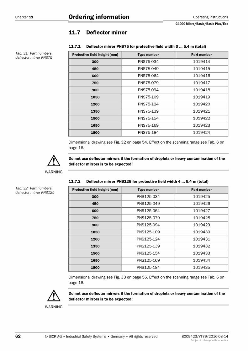
Chapter 11 Operating Instructions
C4000 Micro/Basic/Basic Plus/Eco
62 © SICK AG • Industrial Safety Systems • Germany • All rights reserved 8009423/YT79/2016-03-14Subject to change without notice
Ordering information
11.7 Deflector mirror
11.7.1 Deflector mirror PNS75 for protective field width 0 … 5.4 m (total)
Protective field height [mm] Type number Part number
300 PNS75-034 1019414
450 PNS75-049 1019415
600 PNS75-064 1019416
750 PNS75-079 1019417
900 PNS75-094 1019418
1050 PNS75-109 1019419
1200 PNS75-124 1019420
1350 PNS75-139 1019421
1500 PNS75-154 1019422
1650 PNS75-169 1019423
1800 PNS75-184 1019424
Dimensional drawing see Fig. 32 on page 54. Effect on the scanning range see Tab. 6 onpage 16.
Do not use deflector mirrors if the formation of droplets or heavy contamination of thedeflector mirrors is to be expected!
11.7.2 Deflector mirror PNS125 for protective field width 4 … 5.4 m (total)
Protective field height [mm] Type number Part number
300 PNS125-034 1019425
450 PNS125-049 1019426
600 PNS125-064 1019427
750 PNS125-079 1019428
900 PNS125-094 1019429
1050 PNS125-109 1019430
1200 PNS125-124 1019431
1350 PNS125-139 1019432
1500 PNS125-154 1019433
1650 PNS125-169 1019434
1800 PNS125-184 1019435
Dimensional drawing see Fig. 33 on page 55. Effect on the scanning range see Tab. 6 onpage 16.
Do not use deflector mirrors if the formation of droplets or heavy contamination of thedeflector mirrors is to be expected!
Tab. 31: Part numbers,deflector mirror PNS75
WARNING
Tab. 32: Part numbers,deflector mirror PNS125
WARNING

Operating Instructions Chapter 11
C4000 Micro/Basic/Basic Plus/Eco
8009423/YT79/2016-03-14 © SICK AG • Industrial Safety Systems • Germany • All rights reserved 63Subject to change without notice
Ordering information
11.8 AccessoriesPart Part number
C4000 Basic
Hirschmann cable socket M26 × 6 + FE, crimp contacts, straight 6006612
Hirschmann cable socket M26 × 6 + FE, screw contacts, angled 6007363
Connection cable
Socket straight/stripped, 2.5 m 2023993
Socket straight/stripped, 5 m 2023994
Socket straight/stripped, 7.5 m 2023995
Socket straight/stripped, 10 m 2023996
Socket straight/stripped, 15 m 2023997
Socket straight/stripped, 20 m 2023998
Socket straight/stripped, 30 m 2023999
C4000 Micro/Basic Plus
Cable socket M12 × 7 + FE (max. 0,75 mm²), straight 6028422
Connection cable 7 × 0.25 + FE
Socket straight/stripped, 2.5 m 6020537
Socket straight/stripped, 5 m 6020354
Socket straight/stripped, 7.5 m 6020353
Socket straight/stripped, 10 m 6020352
Socket straight/stripped, 15 m 6020872
Socket angled/stripped, 5 m 6021342
Socket angled/stripped, 15 m 6021343
C4000 Eco
Connection cable 4 × 0.25 + FE
Socket straight/stripped, 2 m 6008899
Socket straight/stripped, 5 m 6009868
Socket straight/stripped, 10 m 6010544
Socket straight/stripped, 15 m 6029215
Connecting cable (4 × 0.25 + FE) for connection to T-distributor
Plug straight/socket straight, 0.6 m 6025930
Plug straight/socket straight, 2 m 6025931
T-distributor to connection for connecting cable 6030664
Mounting kit 1 for C4000 Micro and C4000 Basic Plus
Swivel mount, 4 pcs. for any protective field height 2019649
Mounting kit 2 for C4000 Basic, C4000 Eco andPNS deflector mirror
Swivel mount, 4 pcs. for any protective field height 2019659
Mounting kit 6
Swivel function (side bracket), 4 pcs. for any protective field heightFor higher vibration and shock exposure
2019506
Tab. 33: Part numbers,accessories

Chapter 11 Operating Instructions
C4000 Micro/Basic/Basic Plus/Eco
64 © SICK AG • Industrial Safety Systems • Germany • All rights reserved 8009423/YT79/2016-03-14Subject to change without notice
Ordering information
Part Part number
Laser alignment aid AR60
Laser alignment aid AR60 1015741
Adapter for AR60, large (is required for C4000 Basic) 4032461
Adapter for AR60, small (is required for C4000 Micro) 4032462
Accessories included in a standard delivery
Sliding nuts for side bracket, 4 pcs. 2017550
Operating instructions C4000 Micro/Basic/Eco on CD-ROM 2026783
Reset tool
Adapter cable for reset tool
6022103
2026866

Operating Instructions Chapter 12
C4000 Micro/Basic/Basic Plus/Eco
8009423/YT79/2016-03-14 © SICK AG • Industrial Safety Systems • Germany • All rights reserved 65Subject to change without notice
Annex
12 Annex
12.1 Compliance with EU directives
EU declaration of conformity (excerpt)
The undersigned, representing the following manufacturer herewith declares that theproduct is in conformity with the provisions of the following EU directive(s) (including allapplicable amendments), and that the respective standards and/or technical specifica-tions are taken as the basis.
Complete EU declaration of conformity for download: www.sick.com

Chapter 12 Operating Instructions
C4000 Micro/Basic/Basic Plus/Eco
66 © SICK AG • Industrial Safety Systems • Germany • All rights reserved 8009423/YT79/2016-03-14Subject to change without notice
Annex
12.2 Checklist for the manufacturer
ΚChecklist for the manufacturer/OEM for the installation of
electro-sensitive protective equipment (ESPE)
The details on the items listed below must be available at the latest when the system is commissioned forthe first time, depending, however, on the various applications the requirements of which must be reviewed by themanufacturer/OEM.
This checklist should be retained and kept with the machine documentation to serve as reference during recurringtests.
1. Have the safety rules and regulations been observed in compliance with the directives/standards applicable tothe machine?
Yesÿ Noÿ
2. Are the applied directives and standards listed in the declaration of conformity? Yesÿ Noÿ
3. Does the protective device comply with the required PL/SIL claim limit and PFHd in accordance withEN ISO 13849-1/EN 62061 and the required type in accordance with IEC 61496-1?
Yesÿ Noÿ
4. Is the access to the hazardous area/hazardous point only possible through the protective field of the ESPE? Yesÿ Noÿ
5. Have appropriate measures been taken to protect (mechanical protection) or monitor (protective devices) anypersons or objects in the hazardous area when protecting a hazardous area or hazardous point, and have thesedevices been secured or locked to prevent their removal?
Yesÿ Noÿ
6. Are additional mechanical protective measures fitted and secured against manipulation which prevent reachingbelow, above or behind the ESPE?
Yesÿ Noÿ
7. Has the maximum stopping and/or run-down time of the machine been measured, specified and documented (atthe machine and/or in the machine documentation)?
Yesÿ Noÿ
8. Has the ESPE been mounted such that the required minimum distance from the nearest hazardous point hasbeen achieved?
Yesÿ Noÿ
9. Are the ESPE devices correctly mounted and secured against manipulation after adjustment? Yesÿ Noÿ
10. Are the required protective measures against electric shock in effect (protection class)? Yesÿ Noÿ
11. Is the control switch for resetting the protective devices (ESPE) or restarting the machine present and correctlyinstalled?
Yesÿ Noÿ
12. Are the outputs of the ESPE (OSSD) integrated according to required PL/SILCL compliant withEN ISO 13849-1/EN 62061 and does the integration correspond to the comply with the circuit diagrams?
Yesÿ Noÿ
13. Has the protective function been checked in compliance with the test notes of this documentation? Yesÿ Noÿ
14. Are the specified protective functions effective at every operating mode that can be set? Yesÿ Noÿ
15. Are the switching elements activated by the ESPE, e.g. contactors, valves, monitored? Yesÿ Noÿ
16. Is the ESPE effective over the entire period of the dangerous state? Yesÿ Noÿ
17. Once initiated, will a dangerous state be stopped when switching the ESPE on or off and when changing theoperating mode, or when switching to another protective device?
Yesÿ Noÿ
18. Has the information label “Important Information” for the daily check been attached so that it is well visible for theoperator?
Yesÿ Noÿ
This checklist does not replace the initial commissioning, nor the regular inspection by qualified safety personnel.

Operating Instructions Chapter 12
C4000 Micro/Basic/Basic Plus/Eco
8009423/YT79/2016-03-14 © SICK AG • Industrial Safety Systems • Germany • All rights reserved 67Subject to change without notice
Annex
12.3 List of tablesTab. 1: C4000 Basic model overview .............................................................................11
Tab. 2: C4000 Micro model overview.............................................................................11
Tab. 3: C4000 Eco model overview ................................................................................11
Tab. 4: Permissible configuration of the restart interlock of the C4000Micro/Basic.........................................................................................................14
Tab. 5: Scanning range of the C4000 without and with additional front screen ............16
Tab. 6: Scanning range when using 1 or 2 deflector mirrors..........................................16
Tab. 7: Status indicators of the sender...........................................................................17
Tab. 8: Status indicators of the receiver .........................................................................18
Tab. 9: Pin assignment system connection C4000 Basic (M26 × 6 + FE).......................31
Tab. 10: Pin assignment system connection C4000 Eco (M12 × 4 + FE) .........................31
Tab. 11: Pin assignment system connection C4000 Micro/Basic Plus(M12 × 7 + FE).....................................................................................................32
Tab. 12: Displays shown during the power-up cycle .........................................................37
Tab. 13: Display values during the alignment of sender and receiver ..............................38
Tab. 14: Error displays of the LEDs...................................................................................43
Tab. 15: Error displays of the 7-segment display..............................................................44
Tab. 16: Technical data C4000 Basic/Micro/Eco.............................................................45
Tab. 17: Number of beams depending on the protective field height and thephysical resolution ..............................................................................................49
Tab. 18: Response time depending on the number of beams..........................................49
Tab. 19: Weight of sender and receiver ............................................................................50
Tab. 20: Weight of the deflector mirrors PNS75 and PNS125..........................................50
Tab. 21: Dimensions dependent on the protective field height, C4000 Basic/Ecosender.................................................................................................................51
Tab. 22: Dimensions dependent on the protective field height, C4000 Microsender.................................................................................................................52
Tab. 23: Dimensions of the swivel mount bracket dependent on the housing profile......53
Tab. 24: Dimensions for the deflector mirror PNS75 dependent on the mirrorheight..................................................................................................................54
Tab. 25: Dimensions for the deflector mirror PNS125 dependent on the mirrorheight..................................................................................................................55
Tab. 26: Part numbers C4000 Basic (M26 × 6 + FE) ........................................................57
Tab. 27: Part numbers C4000 Eco (M12 × 4 + FE) ...........................................................58
Tab. 28: Part numbers C4000 Basic Plus (M12 × 7 + FE).................................................59
Tab. 29: Part numbers C4000 Micro ................................................................................60
Tab. 30: Part numbers, additional front screen (weld spark guard)..................................61
Tab. 31: Part numbers, deflector mirror PNS75 ...............................................................62
Tab. 32: Part numbers, deflector mirror PNS125 .............................................................62
Tab. 33: Part numbers, accessories .................................................................................63

Chapter 12 Operating Instructions
C4000 Micro/Basic/Basic Plus/Eco
68 © SICK AG • Industrial Safety Systems • Germany • All rights reserved 8009423/YT79/2016-03-14Subject to change without notice
Annex
12.4 List of illustrationsFig. 1: Components of the C4000................................................................................. 12
Fig. 2: Protecting hazardous points with a safety light curtain C4000.......................... 13
Fig. 3: Hazardous area protection with a safety light curtain C4000............................ 13
Fig. 4: Access protection using a safety light curtain C4000........................................ 13
Fig. 5: Outline drawing of the protective operation ....................................................... 14
Fig. 6: Status indicators of the sender.......................................................................... 17
Fig. 7: Status indicators of the receiver ........................................................................ 18
Fig. 8: Safety distance from the hazardous point ......................................................... 20
Fig. 9: Minimum distance to reflective surfaces ........................................................... 22
Fig. 10: Graph, minimum distance from reflective surfaces ........................................... 22
Fig. 11: Unwanted influencing of a 2nd C4000 system. ................................................. 23
Fig. 12: Reversing the transmission direction of systems in close proximity. ................. 23
Fig. 13: The correct installation (above) must eliminate the errors (below) steppingbehind, reaching below and reaching above...................................................... 24
Fig. 14: Composition of the swivel mount bracket .......................................................... 25
Fig. 15: Mounting sender and receiver using swivel mount brackets ............................. 26
Fig. 16: Composition of the side bracket ........................................................................ 27
Fig. 17: Mounting the C4000 with side bracket.............................................................. 28
Fig. 18: Pin assignment system connection C4000 Basic (M26 × 6 + FE)...................... 31
Fig. 19: Pin assignment system connection C4000 Eco (M12 × 4 + FE)......................... 31
Fig. 20: Pin assignment system connection C4000 Micro/Basic Plus(M12 × 7 + FE).................................................................................................... 32
Fig. 21: Connecting the contact elements to the EDM.................................................... 33
Fig. 22: Connection of the reset button on the C4000 Micro/Basic ............................... 34
Fig. 23: Connection of the sender test button................................................................. 34
Fig. 24: Switching example for C4000 Basic on UE48-20S ............................................ 35
Fig. 25: Switching example for C4000 Micro/Basic on UE10-30S.................................. 36
Fig. 26: Daily checks of the protective device................................................................. 39
Fig. 27: Time sequence diagram of the start-up configuration ....................................... 41
Fig. 28: Dimensional drawing C4000 Basic/Basic Plus/Ecosender (mm)...................... 51
Fig. 29: Dimensional drawing C4000 Micro sender (mm) .............................................. 52
Fig. 30: Dimensional drawing swivel mount bracket (mm) ............................................. 53
Fig. 31: Dimensional drawing, side bracket (mm)........................................................... 53
Fig. 32: Dimensional drawing deflector mirror PNS75 (mm)........................................... 54
Fig. 33: Dimensional drawing deflector mirror PNS125 (mm) ........................................ 55

Operating Instructions Chapter 12
C4000 Micro/Basic/Basic Plus/Eco
8009423/YT79/2016-03-14 © SICK AG • Industrial Safety Systems • Germany • All rights reserved 69Subject to change without notice
Annex

Chapter 12 Operating Instructions
C4000 Micro/Basic/Basic Plus/Eco
70 © SICK AG • Industrial Safety Systems • Germany • All rights reserved 8009423/YT79/2016-03-14Subject to change without notice
Annex

Operating Instructions Chapter 12
C4000 Micro/Basic/Basic Plus/Eco
8009423/YT79/2016-03-14 © SICK AG • Industrial Safety Systems • Germany • All rights reserved 71Subject to change without notice
Annex

SICK AG | Waldkirch | Germany | www.sick.com
8009
423/
YT79
/201
6-03
-14
∙ REI
PA/X
X (2
016-
06) ∙
A4
sw in
t45
More representatives and agencies at www.sick.com
AustraliaPhone +61 3 9457 0600 1800 334 802 – tollfreeE-Mail [email protected]
AustriaPhone +43 22 36 62 28 8-0E-Mail [email protected]
Belgium/LuxembourgPhone +32 2 466 55 66E-Mail [email protected]
BrazilPhone +55 11 3215-4900E-Mail [email protected]
CanadaPhone +1 905 771 14 44E-Mail [email protected]
Czech RepublicPhone +420 2 57 91 18 50E-Mail [email protected]
ChilePhone +56 2 2274 7430E-Mail [email protected]
ChinaPhone +86 20 2882 3600E-Mail [email protected]
DenmarkPhone +45 45 82 64 00E-Mail [email protected]
FinlandPhone +358-9-2515 800E-Mail [email protected]
FrancePhone +33 1 64 62 35 00E-Mail [email protected]
GemanyPhone +49 211 5301-301E-Mail [email protected]
Hong KongPhone +852 2153 6300E-Mail [email protected]
HungaryPhone +36 1 371 2680E-Mail [email protected]
IndiaPhone +91 22 4033 8333E-Mail [email protected]
IsraelPhone +972 4 6881000E-Mail [email protected]
ItalyPhone +39 02 274341E-Mail [email protected]
JapanPhone +81 3 5309 2112E-Mail [email protected]
MalaysiaPhone +6 03 8080 7425E-Mail [email protected]
MexicoPhone +52 472 748 9451E-Mail [email protected]
NetherlandsPhone +31 30 2044 000E-Mail [email protected]
New Zealand Phone +64 9 415 0459 0800 222 278 – tollfreeE-Mail [email protected]
Norway Phone +47 67 81 50 00E-Mail [email protected]
PolandPhone +48 22 539 41 00E-Mail [email protected]
RomaniaPhone +40 356 171 120 E-Mail [email protected]
RussiaPhone +7 495 775 05 30E-Mail [email protected]
SingaporePhone +65 6744 3732E-Mail [email protected]
SlovakiaPhone +421 482 901201E-Mail [email protected]
SloveniaPhone +386 591 788 49E-Mail [email protected]
South AfricaPhone +27 11 472 3733E-Mail [email protected]
South KoreaPhone +82 2 786 6321E-Mail [email protected]
SpainPhone +34 93 480 31 00E-Mail [email protected]
SwedenPhone +46 10 110 10 00E-Mail [email protected]
SwitzerlandPhone +41 41 619 29 39E-Mail [email protected]
TaiwanPhone +886 2 2375-6288E-Mail [email protected]
ThailandPhone +66 2645 0009E-Mail [email protected]
TurkeyPhone +90 216 528 50 00E-Mail [email protected]
United Arab EmiratesPhone +971 4 88 65 878E-Mail [email protected]
United KingdomPhone +44 1727 831121E-Mail [email protected]
USAPhone +1 800 325 7425 E-Mail [email protected]
VietnamPhone +84 945452999E-Mail [email protected]