C270 Conductivity Resistivity Temp Monitorresourcewebsite.singoo.cc/15540905573817771/en/pdf... ·...
24
C270 CONDUCTIVITY MONITOR OPERATION GUIDE
Transcript of C270 Conductivity Resistivity Temp Monitorresourcewebsite.singoo.cc/15540905573817771/en/pdf... ·...
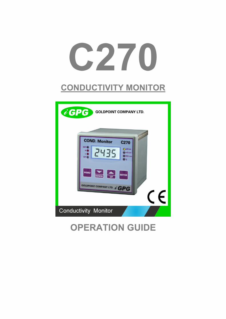
C270 CONDUCTIVITY MONITOR
OPERATION GUIDE
1
CONTENTS 1. INTRODUCTION....... 2
2. FEATURES AND TECHNICAL SPECIFICATIONS.… 2
2.1 Features........ 2
2.2 Technical Specifications........ 2
3. INSTALLATION..... 2
3.1 Dimension........ 3
3.2 Panel Cut-out....... 4
3.3 User Interface and Description.. 4
3.4 Connection........... 6
4. SETTING AND OPERATION...... 7
4.1 Switch Measuring and Setting Mode.................. 8
4.2 Menu Structure........ 8
4.3 Parameter Setting and Operation........ 11
4.3.1 Set Alarm........ 11
4.3.2 Calibration.......... 12
4.3.3 Temperature Compensation.... 14
4.3.4 Set Current Output........ 15
4.3.5 Measurement Mode...... 17
4.3.6 Select cell constant....... 18
4.3.7 Set TDS coefficient....... 18
4.3.8 Restore Factory Setting.... 18
5. ERROR CODES........... 19
6. SENSOR..... 19
7. WARRANTY... 22
8. STANDARD CONFIGURATION..... 22
9. OPTIONAL CONFIGURATION....... 22
2
C270 Intelligent On-line Conductivity Monitor
1. INTRODUCTION
The C270 is a microprocessor controlled conductivity measurement
instrument. The unit utilizes a multifunction LCD to display readings and
provide feedback to the user. It is available with different option to
provide fully configurable control, alarm and feedback with up to two
relays and 4-20mA current output sources.
2. FEATURES AND TECHNICAL SPECIFICATIONS
2.1 Features
(1) 4 LCD digital with back-lit display
(2) Measured conductivity, resistivity, TDS, temperature
(3) 0 ~ 100 automatic/manual temperature compensation
(4) Manual or Automatic buffer adjustment
(5) Restore factory setting function is available
(6) Galvanic separation between inputs and outputs and supply voltage
(7) Different input for excellent noise rejection
(8) High and low programmable alarm, 250V/10A relay output
2.2 Technical Specifications
(1) Ranges of measurement: 0~18 MΩ· cm or 0~19.99uS/cm,
0~999.9uS/cm, 0~9999uS/cm, 0~100mS/cm,0~10000ppm
(2) Accuracy:±0.5 F.S / ±0.2
(3) Linearity:±0.1% of range
(4) Repeatability:±0.1% of range
(5) Temperature compensation type:Auto / manual 0 to 100
(6) Alarm Output:Two relays outputs (250V/10A), full range with
hysteresis adjustable
(7) Current output:DC 4~20mA,Opto-isolated outputs,( 750Ω Max.
3
load)
(8) Ambient Operating temperature:-10~+55
(9) Humidity:≤95%
(10) Power supply:AC110 ~220V,50~60Hz
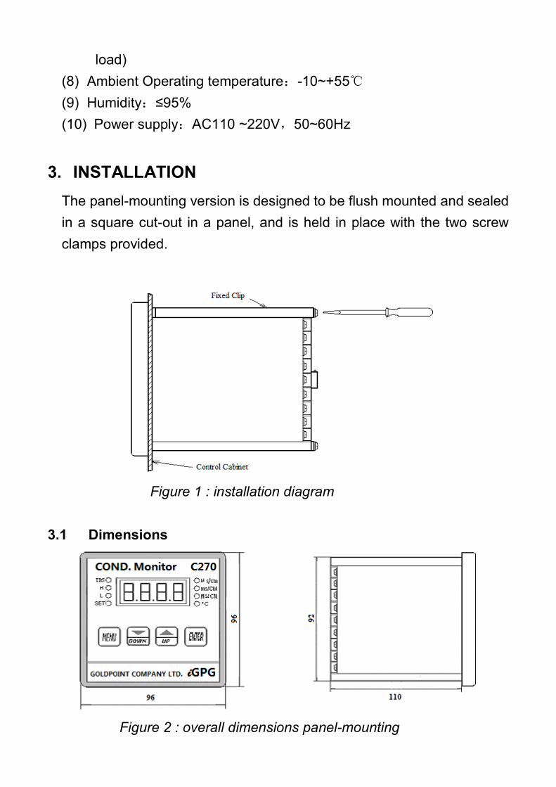
3. INSTALLATION
The panel-mounting version is designed to be flush mounted and sealed
in a square cut-out in a panel, and is held in place with the two screw
clamps provided.
3.1 Dimensions
Figure 2 : overall dimensions panel-mounting
Figure 1 : installation diagram
4
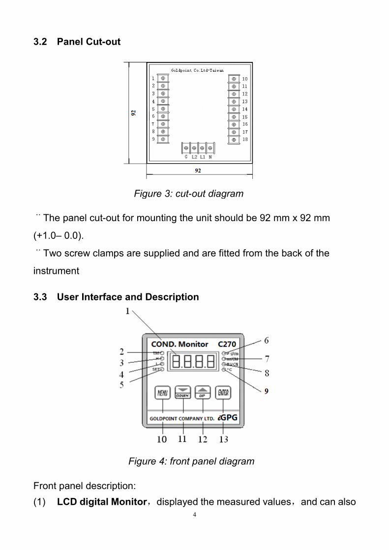
3.2 Panel Cut-out
¨The panel cut-out for mounting the unit should be 92 mm x 92 mm
(+1.0– 0.0).
¨Two screw clamps are supplied and are fitted from the back of the
instrument
3.3 User Interface and Description
Front panel description:
(1) LCD digital Monitor,displayed the measured values,and can also
Figure 3: cut-out diagram
Figure 4: front panel diagram
5
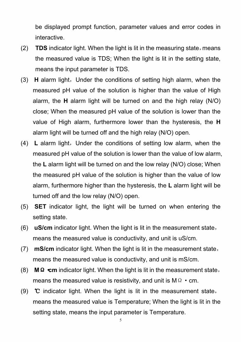
be displayed prompt function, parameter values and error codes in
interactive.
(2) TDS indicator light. When the light is lit in the measuring state,means
the measured value is TDS; When the light is lit in the setting state,
means the input parameter is TDS.
(3) H alarm light,Under the conditions of setting high alarm, when the
measured pH value of the solution is higher than the value of High
alarm, the H alarm light will be turned on and the high relay (N/O)
close; When the measured pH value of the solution is lower than the
value of High alarm, furthermore lower than the hysteresis, the H
alarm light will be turned off and the high relay (N/O) open.
(4) L alarm light,Under the conditions of setting low alarm, when the
measured pH value of the solution is lower than the value of low alarm,
the L alarm light will be turned on and the low relay (N/O) close; When
the measured pH value of the solution is higher than the value of low
alarm, furthermore higher than the hysteresis, the L alarm light will be
turned off and the low relay (N/O) open.
(5) SET indicator light, the light will be turned on when entering the
setting state.
(6) uS/cm indicator light. When the light is lit in the measurement state,
means the measured value is conductivity, and unit is uS/cm.
(7) mS/cm indicator light. When the light is lit in the measurement state,
means the measured value is conductivity, and unit is mS/cm.
(8) MΩΩΩΩ····cm indicator light. When the light is lit in the measurement state,
means the measured value is resistivity, and unit is MΩ·cm.
(9) indicator light. When the light is lit in the measurement state,
means the measured value is Temperature; When the light is lit in the
setting state, means the input parameter is Temperature.
6
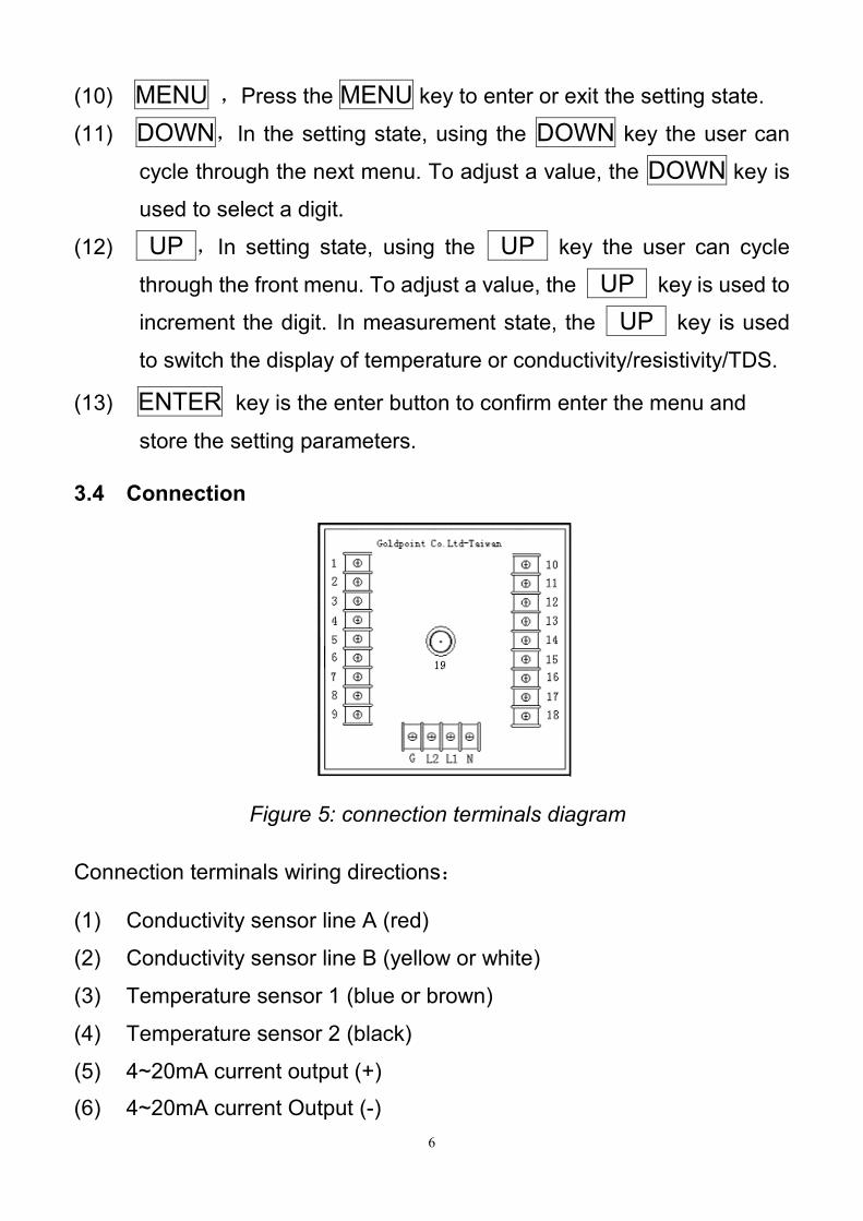
(10) MENU ,Press the MENU key to enter or exit the setting state.
(11) DOWN,In the setting state, using the DOWN key the user can
cycle through the next menu. To adjust a value, the DOWN key is
used to select a digit.
(12) UP ,In setting state, using the UP key the user can cycle
through the front menu. To adjust a value, the UP key is used to
increment the digit. In measurement state, the UP key is used
to switch the display of temperature or conductivity/resistivity/TDS.
(13) ENTER key is the enter button to confirm enter the menu and
store the setting parameters.
3.4 Connection
Connection terminals wiring directions:
(1) Conductivity sensor line A (red)
(2) Conductivity sensor line B (yellow or white)
(3) Temperature sensor 1 (blue or brown)
(4) Temperature sensor 2 (black)
(5) 4~20mA current output (+)
(6) 4~20mA current Output (-)
Figure 5: connection terminals diagram
7
(7) Spare
(8) Spare
(9) Spare
(10) High/Low alarm relay(Common)
(11) Spare
(12) High alarm relay(N/O, normally open)
(13) Low alarm relay(N/O, normally open)
(14) Spare
(15) Spare
(16) Spare
(17) Spare
(18) Spare
(G) Ground
(L2) Spare
(L1) Power supply terminal: Connect AC110 ~ 220V
(N) Power supply terminal: Connect the power supply phase
CAUTION ! :
The specified performance of the C270 is entirely dependent on correct
installation. For this reason, the installer should thoroughly read the
instructions before attempting to make any electrical connections to the
unit.
4. SETTING AND OPERATION
After installation, check the connection is correct, then put the sensor
into the test solution, preheat for 10 minutes, you can perform the
following operations.
8
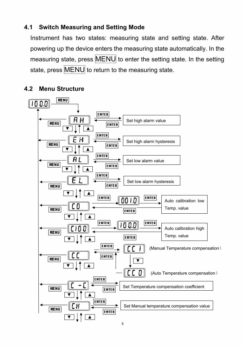
Set high alarm hysteresis
4.1 Switch Measuring and Setting Mode
Instrument has two states: measuring state and setting state. After
powering up the device enters the measuring state automatically. In the
measuring state, press MENU to enter the setting state. In the setting
state, press MENU to return to the measuring state.
4.2 Menu Structure
(Manual Temperature compensation)
Set high alarm value
Set low alarm value
Set low alarm hysteresis
Set Temperature compensation coefficient
Set Manual temperature compensation value
Auto calibration low
Temp. value
Auto calibration high
Temp. value
(Auto Temperature compensation)
9
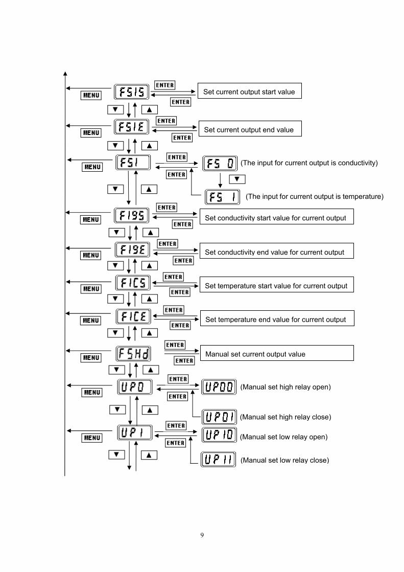
(The input for current output is conductivity)
(Manual set low relay close)
(Manual set low relay open)
(Manual set high relay close)
Set current output start value
Set current output end value
Set conductivity start value for current output
Set conductivity end value for current output
Set temperature start value for current output
Set temperature end value for current output
Manual set current output value
(Manual set high relay open)
(The input for current output is temperature)
10
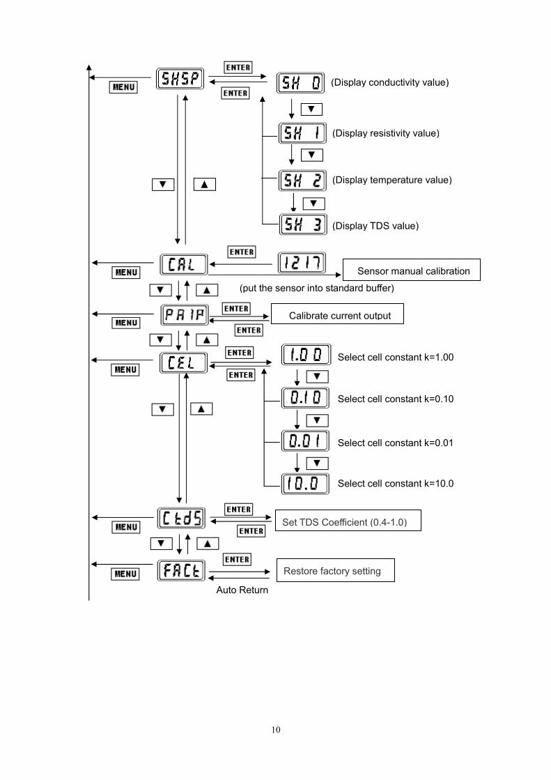
(put the sensor into standard buffer)
Select cell constant k=0.01
(Display temperature value)
Select cell constant k=0.10
Select cell constant k=1.00
(Display TDS value)
(Display resistivity value)
(Display conductivity value)
Restore factory setting
Select cell constant k=10.0
Sensor manual calibration
Calibrate current output
Auto Return
Set TDS Coefficient (0.4-1.0)
11
4.3 Parameter Setting and Operation
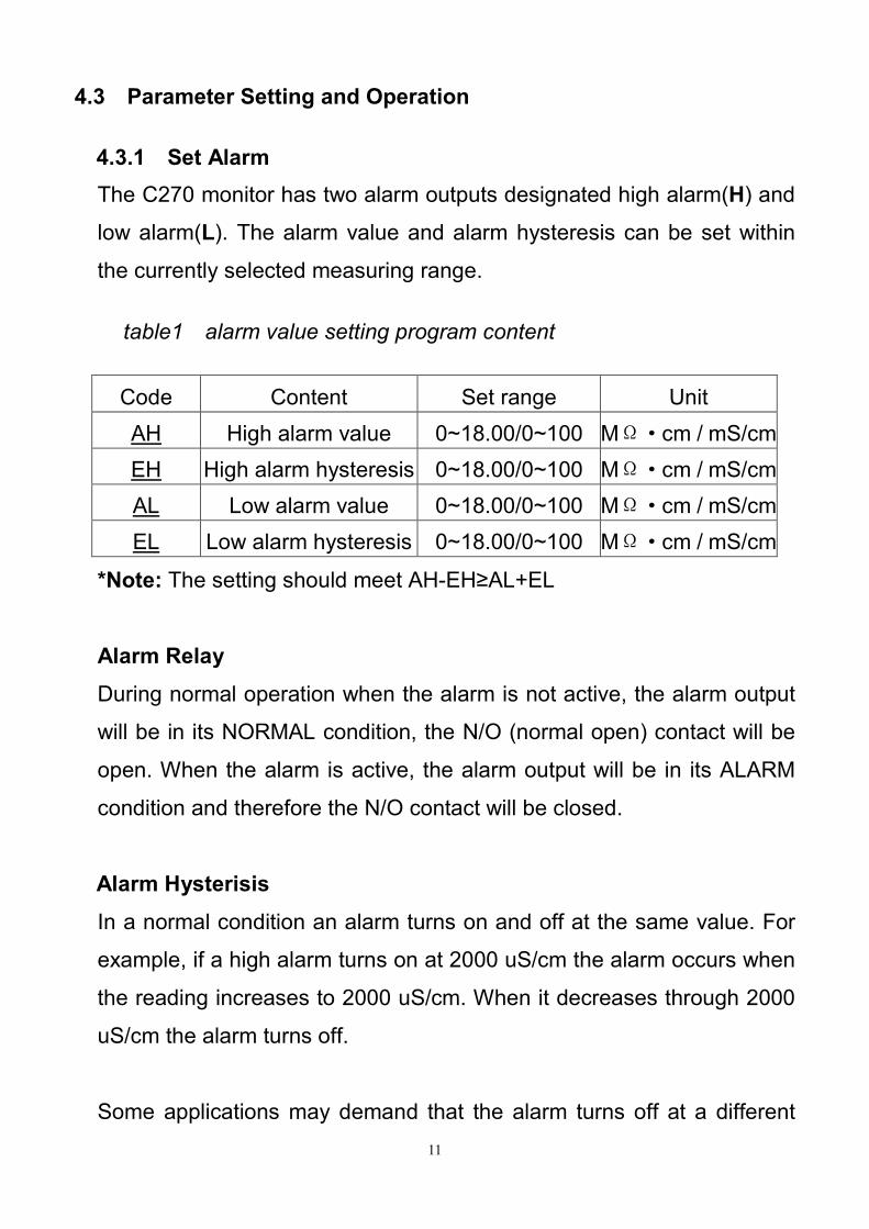
4.3.1 Set Alarm
The C270 monitor has two alarm outputs designated high alarm(H) and
low alarm(L). The alarm value and alarm hysteresis can be set within
the currently selected measuring range.
*Note: The setting should meet AH-EH≥AL+EL
Alarm Relay
During normal operation when the alarm is not active, the alarm output
will be in its NORMAL condition, the N/O (normal open) contact will be
open. When the alarm is active, the alarm output will be in its ALARM
condition and therefore the N/O contact will be closed.
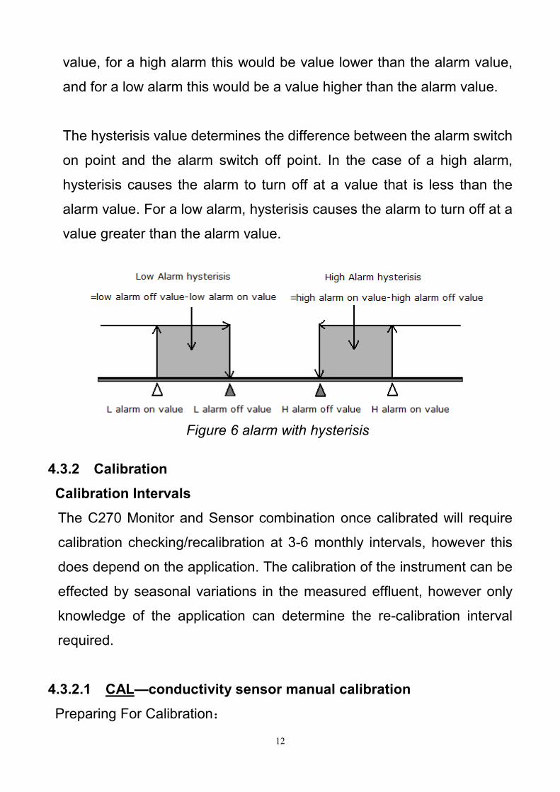
Alarm Hysterisis
In a normal condition an alarm turns on and off at the same value. For
example, if a high alarm turns on at 2000 uS/cm the alarm occurs when
the reading increases to 2000 uS/cm. When it decreases through 2000
uS/cm the alarm turns off.
Some applications may demand that the alarm turns off at a different
Code Content Set range Unit
AH High alarm value 0~18.00/0~100 MΩ·cm / mS/cm
EH High alarm hysteresis 0~18.00/0~100 MΩ·cm / mS/cm
AL Low alarm value 0~18.00/0~100 MΩ·cm / mS/cm
EL Low alarm hysteresis 0~18.00/0~100 MΩ·cm / mS/cm
table1 alarm value setting program content
12
value, for a high alarm this would be value lower than the alarm value,
and for a low alarm this would be a value higher than the alarm value.
The hysterisis value determines the difference between the alarm switch
on point and the alarm switch off point. In the case of a high alarm,
hysterisis causes the alarm to turn off at a value that is less than the
alarm value. For a low alarm, hysterisis causes the alarm to turn off at a
value greater than the alarm value.
4.3.2 Calibration
Calibration Intervals
The C270 Monitor and Sensor combination once calibrated will require
calibration checking/recalibration at 3-6 monthly intervals, however this
does depend on the application. The calibration of the instrument can be
effected by seasonal variations in the measured effluent, however only
knowledge of the application can determine the re-calibration interval
required.
4.3.2.1 CAL—conductivity sensor manual calibration
Preparing For Calibration:
Figure 6 alarm with hysterisis
13
Value known conductivity buffer 100ml;
Pure water 300~500ml;
Use pure water to wash the sensor, and then make it dry;
Use thermometer to measure the temperature of buffer;
Select manual temperature compensation in the instrument menu and
input the temperature value of buffer, set the temperature
compensation coefficient is 0.
Specific operations: select CAL in the menu and put the dry and clean
sensor into the known conductivity buffer solution, press ENTER to enter
its program, then the instrument displays the measured value of the
solution, and in flashing mode which is different from the measurement
states. After the measurement data is stable then press ENTER again,
now only the first digit flashing in the display data means it is modify bit.
Press DOWN to choose the modification bit, press UP key to modify
the data, make the display value as same as the conductivity value of the
solution, press ENTER to store the calibration data(This value is stored
even after power failure), and return to the setting state.
4.3.2.2 C0、、、、C100—temperature calibration
C270 has temperature measurement function, for the automatic
temperature compensation, and also can be displayed on the monitor.
Temperature calibration requires a high and a low constant temperature
environment. Such as ice water mixture (0) and boiling distilled water
(100). C0 is used to calibrate 0. select C0 in the menu and put the
sensor into 0 environment, press ENTER to store the calibration
data , and return to the setting state. The Method of calibrate 100 is as
same as calibrate 0.
14
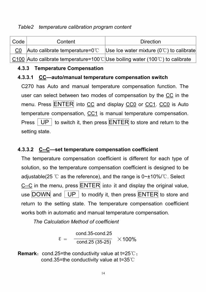
ε= ×100% cond.35-cond.25
Table2 temperature calibration program content
Code Content Direction
C0 Auto calibrate temperature=0 Use Ice water mixture (0) to calibrate
C100 Auto calibrate temperature=100 Use boiling water (100) to calibrate
4.3.3 Temperature Compensation
4.3.3.1 CC—auto/manual temperature compensation switch
C270 has Auto and manual temperature compensation function. The
user can select between two modes of compensation by the CC in the
menu. Press ENTER into CC and display CC0 or CC1. CC0 is Auto
temperature compensation, CC1 is manual temperature compensation.
Press UP to switch it, then press ENTER to store and return to the
setting state.
4.3.3.2 C--C—set temperature compensation coefficient
The temperature compensation coefficient is different for each type of
solution, so the temperature compensation coefficient is designed to be
adjustable(25 as the reference ), and the range is 0~±10%/. Select
C--C in the menu, press ENTER into it and display the original value,
use DOWN and UP to modify it, then press ENTER to store and
return to the setting state. The temperature compensation coefficient
works both in automatic and manual temperature compensation.
The Calculation Method of coefficient
Remark:cond.25=the conductivity value at t=25;
cond.35=the conductivity value at t=35
cond.25 (35-25)
15
Table3 temperature compensation program content
4.3.3.3 CH—set manual temperature
In this mode the instrument should be set with the “CC1” and the
user can set the solution temperature (0~100) in the CH menu. Press
ENTER into CH and display the original value, use UP and DOWN
to modify it, then press ENTER to store and return to the setting state.
Code Content Direction
CC Auto/manual temp. compensation switch 0=Auto/1=manual
C--C Temp. compensation coefficient setting Range: 0~±10%/
CH Manual temperature setting Range: 0~100
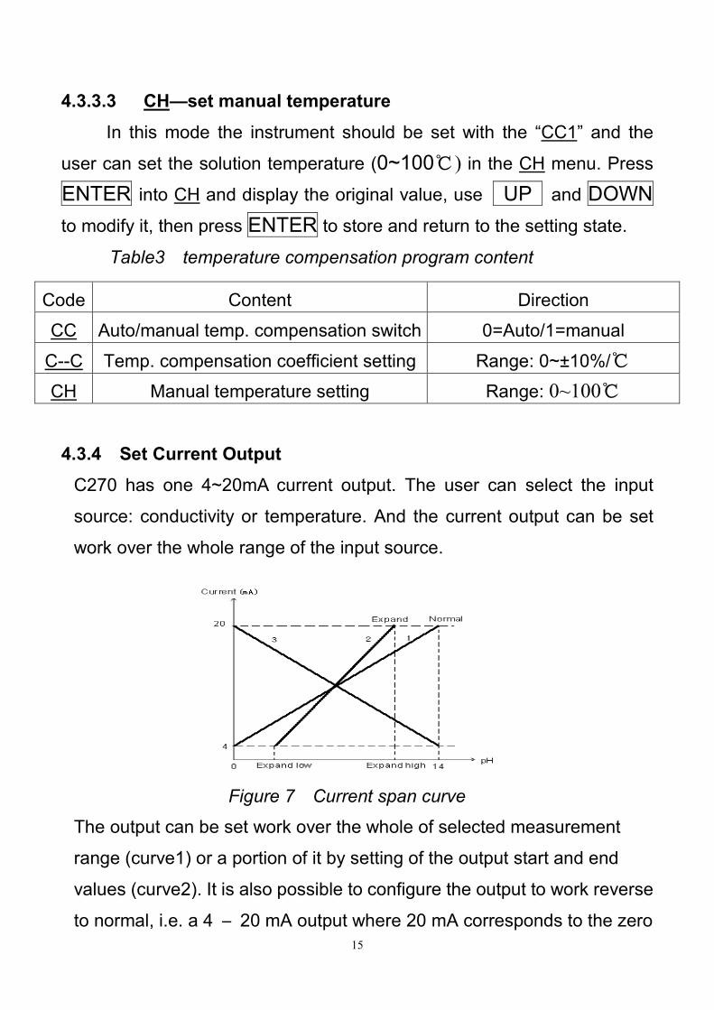
4.3.4 Set Current Output
C270 has one 4~20mA current output. The user can select the input
source: conductivity or temperature. And the current output can be set
work over the whole range of the input source.
The output can be set work over the whole of selected measurement
range (curve1) or a portion of it by setting of the output start and end
values (curve2). It is also possible to configure the output to work reverse
to normal, i.e. a 4 – 20 mA output where 20 mA corresponds to the zero
Figure 7 Current span curve
16
Table6 set current output
display value and 4 mA corresponding to the full scale value. (curve3).
4.3.4.1 FSIS、、、、FSIE—set current output start and end value
Select FSIS in the menu, press ENTER into it and display the original
current output start value, use DOWN and UP to modify it, then
press ENTER to store and return to the setting state.
The same method select FSIE to set the current output end value.
4.3.4.2 FSI—select the input for the current output
Select FSI in the menu, press ENTER into it and display FS 0 or FS 1.
FS 0 is conductivity as the input, FS 1 is temperature as the input.
Press UP to switch it, then Press ENTER to store and return to the
setting state.
Code Content Direction
FSIS Current output start value 4.00~20.00 mA
FSIE Current output end value 4.00~20.00 mA
FSI The input for the current
output
0: conductivity
1: temperature
4.3.4.3 FIgS、、、、FIgE、、、、FICS、、、、FICE—set input value range for the current
output
After selecting the input parameters, you can set its start value and end
value. Select FIgS in the menu, press ENTER into it and display the
original conductivity start value, use DOWN and UP to modify it,
then press ENTER to store and return to the setting state. The same
method select FIgE to set the conductivity end value.
17
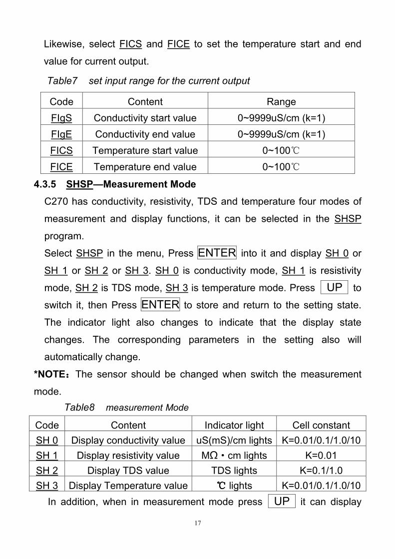
Likewise, select FICS and FICE to set the temperature start and end
value for current output.
Code Content Range
FIgS Conductivity start value 0~9999uS/cm (k=1)
FIgE Conductivity end value 0~9999uS/cm (k=1)
FICS Temperature start value 0~100
FICE Temperature end value 0~100
4.3.5 SHSP—Measurement Mode
C270 has conductivity, resistivity, TDS and temperature four modes of
measurement and display functions, it can be selected in the SHSP
program.
Select SHSP in the menu, Press ENTER into it and display SH 0 or
SH 1 or SH 2 or SH 3. SH 0 is conductivity mode, SH 1 is resistivity
mode, SH 2 is TDS mode, SH 3 is temperature mode. Press UP to
switch it, then Press ENTER to store and return to the setting state.
The indicator light also changes to indicate that the display state
changes. The corresponding parameters in the setting also will
automatically change.
*NOTE::::The sensor should be changed when switch the measurement
mode.
Code Content Indicator light Cell constant
SH 0 Display conductivity value uS(mS)/cm lights K=0.01/0.1/1.0/10
SH 1 Display resistivity value MΩ·cm lights K=0.01
SH 2 Display TDS value TDS lights K=0.1/1.0
SH 3 Display Temperature value lights K=0.01/0.1/1.0/10
In addition, when in measurement mode press UP it can display
Table8 measurement Mode
Table7 set input range for the current output
18
the temperature value, and the Temp. indicator will light. After a few
seconds automatically return to the original measurement mode.
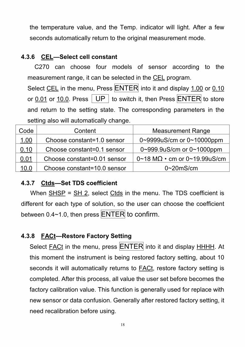
4.3.6 CEL—Select cell constant
C270 can choose four models of sensor according to the
measurement range, it can be selected in the CEL program.
Select CEL in the menu, Press ENTER into it and display 1.00 or 0.10
or 0.01 or 10.0. Press UP to switch it, then Press ENTER to store
and return to the setting state. The corresponding parameters in the
setting also will automatically change.
Code Content Measurement Range
1.00 Choose constant=1.0 sensor 0~9999uS/cm or 0~10000ppm
0.10 Choose constant=0.1 sensor 0~999.9uS/cm or 0~1000ppm
0.01 Choose constant=0.01 sensor 0~18 MΩ·cm or 0~19.99uS/cm
10.0 Choose constant=10.0 sensor 0~20mS/cm
4.3.7 Ctds—Set TDS coefficient
When SHSP = SH 2, select Ctds in the menu. The TDS coefficient is
different for each type of solution, so the user can choose the coefficient
between 0.4~1.0, then press ENTER to confirm.
4.3.8 FACt—Restore Factory Setting
Select FACt in the menu, press ENTER into it and display HHHH. At
this moment the instrument is being restored factory setting, about 10
seconds it will automatically returns to FACt, restore factory setting is
completed. After this process, all value the user set before becomes the
factory calibration value. This function is generally used for replace with
new sensor or data confusion. Generally after restored factory setting, it
need recalibration before using.
19
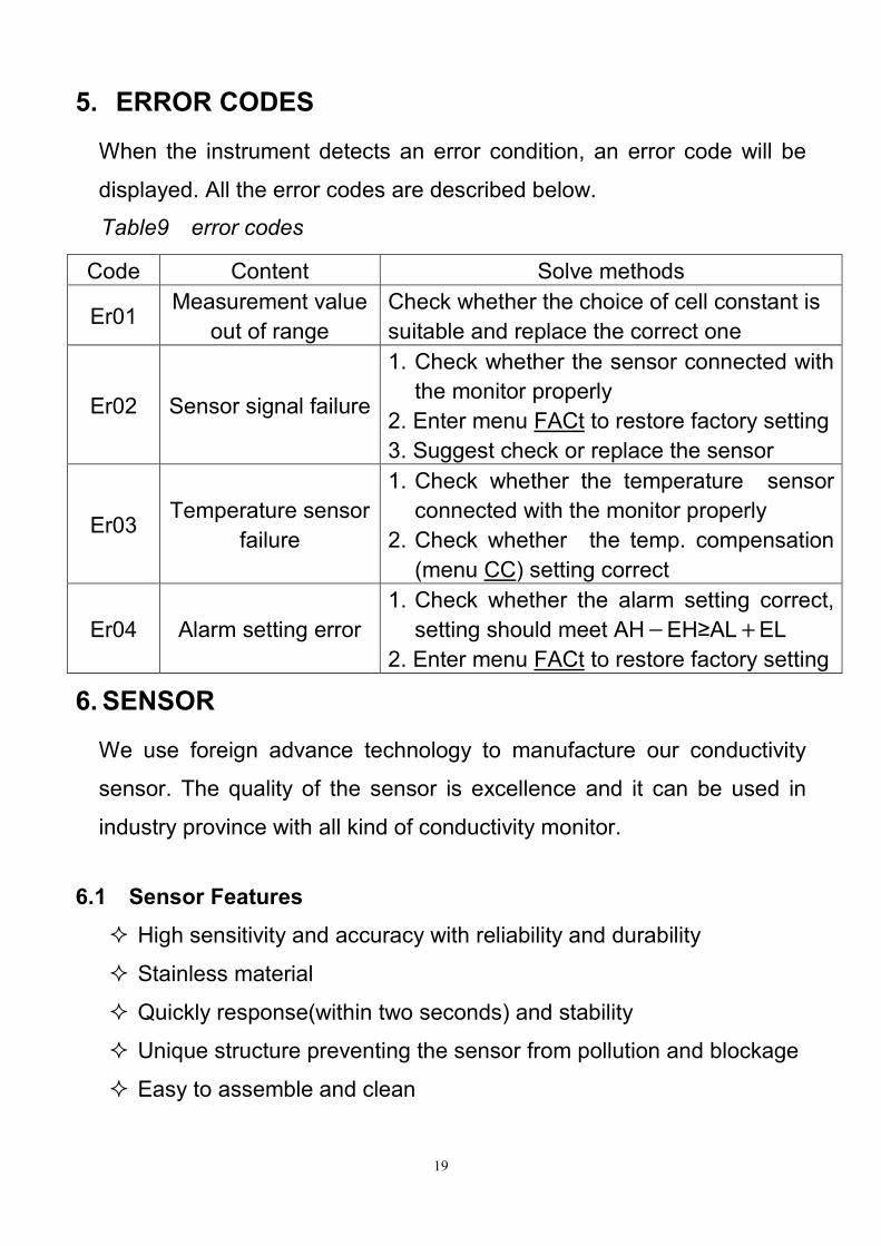
5. ERROR CODES
When the instrument detects an error condition, an error code will be
displayed. All the error codes are described below.
6. SENSOR
We use foreign advance technology to manufacture our conductivity
sensor. The quality of the sensor is excellence and it can be used in
industry province with all kind of conductivity monitor.
6.1 Sensor Features
High sensitivity and accuracy with reliability and durability
Stainless material
Quickly response(within two seconds) and stability
Unique structure preventing the sensor from pollution and blockage
Easy to assemble and clean
Code Content Solve methods
Er01 Measurement value
out of range
Check whether the choice of cell constant is
suitable and replace the correct one
Er02 Sensor signal failure
1. Check whether the sensor connected with
the monitor properly
2. Enter menu FACt to restore factory setting
3. Suggest check or replace the sensor
Er03 Temperature sensor
failure
1. Check whether the temperature sensor
connected with the monitor properly
2. Check whether the temp. compensation
(menu CC) setting correct
Er04 Alarm setting error
1. Check whether the alarm setting correct,
setting should meet AH-EH≥AL+EL
2. Enter menu FACt to restore factory setting
Table9 error codes
20
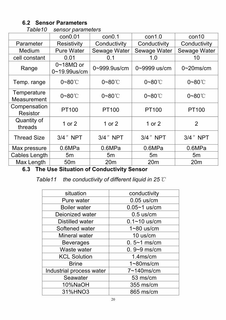
6.2 Sensor Parameters
Table10 sensor parameters
6.3 The Use Situation of Conductivity Sensor
Table11 the conductivity of different liquid in 25
con0.01 con0.1 con1.0 con10
Parameter Resistivity Conductivity Conductivity Conductivity
Medium Pure Water Sewage Water Sewage Water Sewage Water
cell constant 0.01 0.1 1.0 10
Range 0~18MΩ or
0~19.99us/cm 0~999.9us/cm 0~9999 us/cm 0~20ms/cm
Temp. range 0~80 0~80 0~80 0~80
Temperature
Measurement 0~80 0~80 0~80 0~80
Compensation
Resistor PT100 PT100 PT100 PT100
Quantity of
threads 1 or 2 1 or 2 1 or 2 2
Thread Size 3/4″NPT 3/4″NPT 3/4″NPT 3/4″NPT
Max pressure 0.6MPa 0.6MPa 0.6MPa 0.6MPa
Cables Length 5m 5m 5m 5m
Max Length 50m 20m 20m 20m
situation conductivity
Pure water 0.05 us/cm
Boiler water 0.05~1 us/cm
Deionized water 0.5 us/cm
Distilled water 0.1~10 us/cm
Softened water 1~80 us/cm
Mineral water 10 us/cm
Beverages 0. 5~1 ms/cm
Waste water 0. 9~9 ms/cm
KCL Solution 1.4ms/cm
Brine 1~80ms/cm
Industrial process water 7~140ms/cm
Seawater 53 ms/cm
10%NaOH 355 ms/cm
31%HNO3 865 ms/cm
21
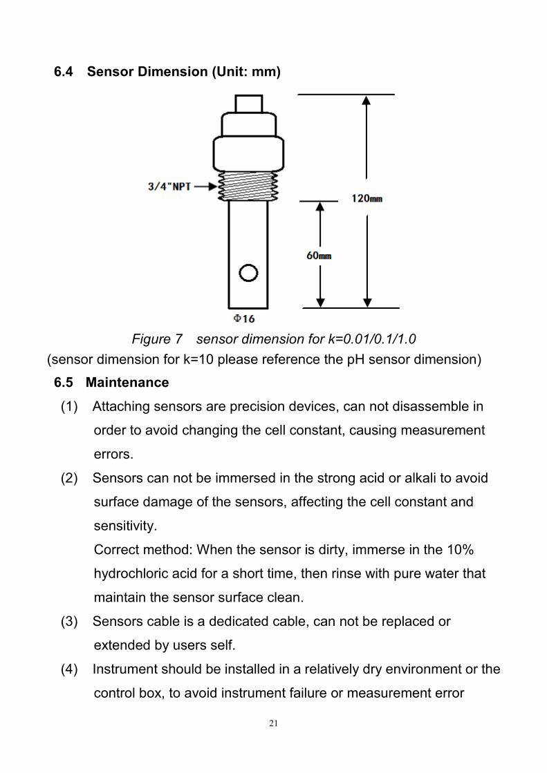
6.4 Sensor Dimension (Unit: mm)
Figure 7 sensor dimension for k=0.01/0.1/1.0
(sensor dimension for k=10 please reference the pH sensor dimension)
6.5 Maintenance
(1) Attaching sensors are precision devices, can not disassemble in
order to avoid changing the cell constant, causing measurement
errors.
(2) Sensors can not be immersed in the strong acid or alkali to avoid
surface damage of the sensors, affecting the cell constant and
sensitivity.
Correct method: When the sensor is dirty, immerse in the 10%
hydrochloric acid for a short time, then rinse with pure water that
maintain the sensor surface clean.
(3) Sensors cable is a dedicated cable, can not be replaced or
extended by users self.
(4) Instrument should be installed in a relatively dry environment or the
control box, to avoid instrument failure or measurement error
22
caused by damp.
7 WARRANTY
Products manufactured by GOLDPOINT company Ltd. are guaranteed
for a period of one year from the date of delivery. Goods for attention
under guarantee must be returned to the factory carriage paid and, if
accepted for free repair, will be returned to the customer’s address free
of charge.
All sensors made by GOLDPOINT company Ltd. are thoroughly tested
to their published specification before delivery. As we have no control
over the conditions in which their sensors are used, no further guarantee
is given.
8 STANDARD CONFIGURATION
C270 monitor
Mounting fixing of monitor
Operation guide
Inspection report
9 OPTIONAL CONFIGURATION
Conductivity sensor con0.1/con1.0/con10 (cable length 5 meters)
Resistivity sensor con0.01 (cable length 5 meters)
Extension cable
23
GOLDPOINT COMPANY LTD.,(TAIWAN) AUTHORIZED
ADD: 4F-1, NO.177, Sec.1, Heping East Road, Taipei
TEL: 00886-2-23584907/08/09/10
FAX: 00886-2-23584959
GOLDPOINT (SHANGHAI) COMPANY LTD., MANUFACTURING
ADD:B601,NO.555,Fahuazhen Road,shanghai
TEL: 0086-021-62826822, 62820823
FAX: 0086-021-62826823
Web:www.igpg.com.cn / www.goldpointgroup.com
Email: [email protected]


![[PSS 6-3C2 A] 871CC Contacting Conductivity and Resistivity Sensors … SENSOR & CABLE.pdf · · 2009-01-07871CC Contacting Conductivity and Resistivity Sensors and Accessories](https://static.fdocuments.in/doc/165x107/5ab54a117f8b9ab7638c91a8/pss-6-3c2-a-871cc-contacting-conductivity-and-resistivity-sensors-sensor-cablepdf2009-01-07871cc.jpg)