C260 ENDE - finskasauna.sk · 3 1. CONTROL UNIT C260 Control unit C260 is intended for the control...
16
19012005 C260 Control unit Ovladaci jednotka CZ EN Harvia Oy PL 12 40951 Muurame Finland www.harvia.fi Finskasauna.cz Slepá 15 Brno 602 00 Tel. 606 646 269
Transcript of C260 ENDE - finskasauna.sk · 3 1. CONTROL UNIT C260 Control unit C260 is intended for the control...

19012005
C260
Control unit
Ovladaci jednotkaCZ
EN
Harvia OyPL 12
40951 MuurameFinland
www.harvia.fi
Finskasauna.czSlepá 15Brno 602 00Tel. 606 646 269
2
EN CZOBSAHCONTENTS
1. CONTROL UNIT C260 ............................................. 31.1. Technical data ................................................. 3
2. C260VKK CONTROL UNIT: INSTRUCTIONS FOR USE ... 42.1. Main Switch (1) ............................................... 42.2. Weekly Timer (Weektimer) (2) ......................... 5
2.2.1. Basic Mode .......................................... 52.2.2. Setting the Weekly Timer to Real Time ... 62.2.3. Programming the Timer ........................ 62.2.4. Manual Control Operations withthe Weekly Timer ........................................... 82.2.5. Checking, Changing and ClearingPrograms and Selecting the Display Mode ........ 8
2.3. Manual Switch (3) ......................................... 102.3.1. Heater On Instantly ............................. 102.3.2. Heater Off .......................................... 10
2.4. Display Screen (4) ......................................... 102.5. Temperature Regulator (5) .............................. 102.6. Indicator Light, Red (6) ................................... 102.7. Indicator Light, Green (7) ................................ 112.8. Indicator Light, Red (8) ................................... 11
3. CONTROL UNIT’S INSTRUCTIONS TO ENGINEER .... 113.1. Installation of the Control Unit C260VKK ......... 11
3.1.1. Removing the Top Plate ...................... 113.1.2. Fastening the Device to the Wall ......... 123.1.3. Electrical Connections ......................... 123.1.4. Altering the Basic Settings ofthe Control Unit ............................................ 133.1.5. Use of the Control Unit by RemoteControl ......................................................... 133.1.6. Indicator Lamp ................................... 13
3.2. Installing the Thermostat’s Sensor Box ............ 143.3. Installing the Power Unit C260K ..................... 15
3.3.1. Removing the Top Plate ...................... 153.3.2. Fastening the Device to the Wall ......... 153.3.3. Electrical connections ......................... 15
1. Ovládací jednotka C260 ............................................... 3 1.1. Technické informace ............................................. 3
2. C260VKK ovládací jednotka: instrukce pro užití .......... 4 2.1. Hlavní vypínac (1) .................................................. 4 2.2. Týdenní casovac (2) ............................................. 5 2.2.1. Základní mód ................................................. 5 2.2.2. Nastavení týdenního casovace do reálného .6 2.2.3. Programování casovace ...............................6 2.2.4. Manuální ovládání operací s týdenním casovacem ....................................8 2.2.5. Kontrola, zmeny, mazání a výber zobrazení 8 2.3. Manuální ovládání (3) .........................................10 2.3.1. Okamžité sepnutí kamen ............................10 2.3.2. Vypnutí kamen ...........................................10 2.4. Zobrazení displeje (4) ........................................10 2.5. Regulace teploty (5) ...........................................10 2.6. Indikátor - cervený (6) ........................................10 2.7. Indikátor - zelený (7) ..........................................11 2.8. Indikátor - cervený (7) ........................................11
3. Ovládací jednotka - instrukce pro odbornou instalaci.11 3.1. Instalace ovládací jednotky C260VKK .................11 3.1.1. Demontáž predního panelu jednotky ............11 3.1.2. Montáž jednotky na zed................................12 3.1.3. Elektrické zapojení ........................................12 3.1.4. Zmeny základního nastavení jednotky .........13 3.1.5. Ovládání jednotky dálkovÿ ............................13 3.1.6. Indikacní kontrolky .........................................13 3.2. Instalace teplotního cidla .......................................14 3.3. Instalace silové jednotky C260K ...........................15 3.3.1. Demontáž prední cásti silové jednotky ..........15 3.3.2. Montáž silové cásti na zed ...........................15 3.3.3. Elektrické zapojení .........................................15
3
1. CONTROL UNIT C260
Control unit C260 is intended for the control of electricheaters fitted with 2 series parallel connectors for use inlarge saunas. Control unit C260 consists of a control unit(C260VKK), a power unit (C260K) and a thermostat.There are two versions of the power unit so the controlunit can be used with heaters that have different poweroutput levels. Power units that are equipped to handlesmaller power output come with 16 A circuit breakerswhich allows them to control sauna heaters with up to 22kW of power output (for instance two 11 kW heaters orone 20 kW heater). The more powerful power units thatcome with 25 A circuit breakers can control saunaheaters with up to 34 kW of power output.
The functions of the control unit are controlled bycomponents in the thermostat’s sensor box.Thetemperature sensor and the overheating limiter arelocated in the sensor box. The temperature is sensedby an NTC thermistor, and there is an overheatinglimiter that can be reset. In case of malfunction, thisoverheating limiter will cut off the heater powerpermanently (the overheating limiter can be reset bypressing the reset button, see Figure 35). Mechanicaldamage to the temperature sensor or overheatinglimiter circuitry (power failure/short circuit) will causean error message (Er1, Er2 or Er3) to appear in thedisplay unit in the control unit, and the power to theheater will be cut off.• Er1= power failure in the temperature sensor
circuit (LO)• Er2= temperature sensor short-circuited• Er3= overheating limiter circuit cut offThe error message will disappear after themalfunction has been corrected.
1.1. Technical data
C260VKK control unit:• maximum setting temperature in the control
unit’s display is 110 °C, setting precision ±1 °C• maximum temperature reading displayed is
125 °C• maximum number of hours the heater stays on
can be set by means of the DIP switch in thecontrol unit , as follows: 6 hs, 12 hs, 18 hs orcontinuously (see engineer’s instruction 3)
• a weekly timer in the control unit is programmedto function during power cuts of up toapproximately two hours
• dimensions of the control unit: breadth 250 mm,height 223 mm and depth approx. 70 mm
• weight approx. 1,1 kgC260K power unit:• dimensions of the power unit: breadth 280 mm,
height 350 mm and depth 110 mm• weight approx. 3 kgThermostat:• temperature sensor NTC thermistor 22kS/T=25 ºC• resettable overheating limiter• dimensions (mm): 51 x 73 x 27• weight 175 g with leads (ca 4 m)
1.OVLADACI JEDNOTKA C260
1.1. Technické informace
EN CZ
Ovladaci jednotka C260 je primarne urcena pro ovladanielektrickych kamen, ktere mají 2 rady paraelních pripojení, které se pouzivaji pro velke komercni sauny. Ridici jednotka se sklada z ovladaci jednotka C260VKK a silove casti C260K a teplotniho cidla.Tyto jednotky se vyrabeji ve 2 provedenich a to podlevýkonu kamen ke kterým je jednotka urcena.Jednotka s oznacenim C260-20 je urcena pro výkony 10,5 - 22 Kw s jistice 16A a C260-34 je pro výkony26 - 34 Kw a jistice jsou 25 A.
Funkce a teplota jsou ovládány pomocí ovládací jednotkya mereny teplotním cidlem, které se umistuje do sauny.Teplotní cidlo a ochrana proti prehrátí je umístenav krabicce cidla teploty. Teplota je snimana pomociNTC termistoru, v prípade prehrátí teplotní ochranavypne kamna a pokud se nestikne resetování teplotní ochrany, kamna se znovu nesepnou. Viz. obr. 35.
Mechanicke poskozeni nebo zkrat zpusobi zobrazeni chyboveho hlaseni (Er1, Er2 nebo Er3 ) a kamna se vypnou.
- Er1 = výpadek napájení v okruhu teplotního cidla- Er2 = teplotní cidlo má zkrácené okruh- Er3 = teplotní ochrana vypla okruh
Chybové zprávy zmiznou po ostraneni vsech poruch.
C260VKK - kontrolni jednotka - maximalni nastaveni teploty v kontrolni jednotce je 110 C, presnost nastaveni je +/- 1 C- maximalni teplota zobrazena na displeji je 125 C- maximalni doba kamen v provozu je podle nastaveniDIP prepinace v kontrolni jednotce. Nastaveno muze byt6h, 12h, 18h nebo nepretrzite ( vice v sekci 3 )Týdenní casovac má záložní baterii a pokud vypadnenapájení, vnitrni pamet s nastavenim se uchova dalsi2 hodiny.- rozmery ovladaci jednotky: sirka 280mm, vyska 350mm a hloubka cca 70mm- váha cca 1,1kg
C260K silova cast:- rozmery silové casti: sirka 280mm, vyska 350 mm a hloubka cca 110mm- vaha: cca 3 kgTermostat: - teplotni cidlo termistor NTC 22Kohm/T = 25 C- resetovaci ochrana proti prehrati- rozmery (mm): 51x73x27- vaha 175g s privodnim kabelem (ca 4 m )

4
2. C260VKK CONTROL UNIT:INSTRUCTIONS FOR USE
Before you switch the heater on check always thatthere aren’t any things over the heater or in the neardistance of the heater.
The control unit is a device for controlling the powerunit (C260K) according to the timer switches (ON/OFF)and the temperatures registered by the thermostat’ssensors. The timer switches can be controlled from thecontrol unit by either pressing the key manually (3) orby pre-setting the time using the weekly timer (2). Thetimer switch may also be set remotely using a separatetime switch, a switching device connected to atelephone line or with a manually controlled switch.Remote control mode comes into force automaticallywhen the normal switch contact points short-circuitthe low-tension control line. The control unit also emitsa 24 volt direct current signal that the heater is on andready for use, for example to the indicator lamp (max1 W).
Normally the control unit is used either by meansof the weekly timer or remote control. There can beno mix of functions as they are prioritized equally andcan muddle up each others’ functions. The manualkey (3), however, allows the heater to be switchedon in exceptional circumstances and programmedtimings consequently need to be changed.
2.1. Main Switch (1)The main switch (1) connects power to the controlunit’s electronics. The main switch must always bein the ON position, so that the heater can beswitched on by means of the manual key (3), whenso desired, by remote control or by means of theprogrammed weekly timer. The display screenshows when the power is on and waits a fewseconds to indicate the temperature of the saunaroom until “OFF” appears in the screen. The unit isnow ready to control the power unit either on sitefrom the control unit itself (manually/weekly timer)or by remote control.
The weekly timer (Weektimer) is poweredseparately from the main switch. The control unit hasbackup power to last for 2 hours, so short powerfailures do not affect the programs stored in the weeklytimer’s memory. In other words, after a short powerfailure, the control unit will continue to follow theweekly timer’s program.
If the power failure exceeds 1 hour and the weeklytimer’s display screen shuts down, the programs areerased. When the power is restored, the display willshow the code “ER8" which means that the weeklytimer needs to be reprogrammed. Before programming,however, use the reset button to reset the weeklytimer and press the manual button until the errormessage “ER8“ disappears.
If control unit is controlled by external control i.e.computer or similar system, control unit will continueto switch the heater on and off normally even after along power failure.
2. C260VKK ovládací jednotka
EN CZ
Instrukce pro užití
2.1. Hlavní vypínac (1)
Pred zapnutim kamen zkontrolujte jestliu kamen nejsou zadne nevhodne predmety, ktere by mohli zpusobit pozar.
Kontrolni jednotka je urcena pro ovladanisilove casti jednotky ( C260K ) podle casove spinani (ON / OFF) a vyhodnocovani teploty podle teplotniho cidla.Ovladani casoveho nastaveni muze byt ovladanomanualne skrz ovladaci panel (3) nebo prednastavenim spinani pomoci tydenniho casovace.(2). Casovac muze byt samozrejme ovladan pomocioddeleneho casovace, spinaci zarizeni muze bytvedeno po telefonni lince nebo manualne ovladany.
Mod dalkoveho ovladani nabehne automaticky kdyz se na normalnich prepinacich kontaktech snizi napetina nizkou uroven. Ovladaci jednotka dava napeti 24V, ze jsou kamna sepnute a pripraveny pro pouziti,priklad. : indikacni kontrolka ( max. 1 W )
Standartne se jednotka pouziva pres tydenni casovacnebo dalkove ovladani. Tyto ruzne moznosti ovladanise nedaji kombinovat.
Hlavni vypinac (1) spína ovladaci jednotku. Hlavni vypinac musi byt v pozici ON pokud chcetekamna ovladat manualne dle (3), dalkove nebopomoci tydeniho casovace. Dislej se rozsviti kdyz ji sepnete a pockatenekolik sekund na zobrazeni teploty v saunedokud se na displeji nezobrazi OFF.Ovladaci jednotka je nyní pripravena pro ovladanisilove casti skrz ovladaci panel na siti nebomanualne, popr. tydennim casovacem.Týdenní casovac ma napajeni oddelene od hlavnihovypinace a v pripade vypadku napajeni ma jednotkazalozni napajeni po dobu cca 2 hodin. Takze setydenni casovani nesmaze. V dalsim kroku bude jednotka pokracovat ve zvolenem tydennim nastaveni.Pokud bude vypadek proudu delsi a zobrazeni didplejese vypne, naprogramovani bude smazano.Kdyz se napajeni obnovi, na displeji se zobrazihlaska ER8, ktera znamena ze se musi casovac znovunastavit. Pred opetovnym programovanim stiknete resetovaci tlacitko na tydennim casovaci a nasledne stiknete tlacitko manualni ovladanidokud chybova hlaska ER8 nezmizi.Kdyz je ovladaci jednotka ovladana externim ovladanim,pocitacem nebo podobnym systemem, ovladat kamna bude okamzite po znovu obnoveni napajeni.

5
The main switch functions like anemergency OFF switch as power to theheater can be disconnected by selectingposition “0“ whether the heater has beenswitched on manually or with the timer.
2.2. Weekly Timer (Weektimer) (2)In addition to its normal clock functions (realtime), the weekly timer shows in the screenat the same time the day of the week, thecurrent control mode (ON/OFF/locked/unlocked), summer time setting (± 1h) and thetwelve-hour clock symbols AM/PM.
The weekly timer has a memory with tenseparate programmable ON/OFF functions,i.e. there are 20 timing programs:• weekday(s),• hour• minute• ON/ OFF• summer/ winter.The timer is programmed by pressing thecontrols below the screen. (Fig. 2)
2.2.1. Basic ModeWhen the weekly timer is switched on therows of numbers and other symbols lightup. Before programming commences, theclock’s settings must be cleared as follows(Fig. 3):• press the [reset] -button once (with the
tip of a pen, for example).• This will remove any erroneous data
contained within the clock. Afterresetting, the screen will remainaccording to the diagram 3 for a while,but then the numbers 1–7 representingthe days of the week will start to flashin the upper part of the screen. (Fig. 4)
2.2.1. Zakladni mod
Figure 1. Control unit: switches andindicator lights
Figure 2.0brazek 2.
Figure 3.0brazek 3.
Figure 4.0brazek 4.
EN CZ
Obrázek 1. Ovládací jednotka: ovládací prvky a
indikacní kontrolky
2.2. Týdenní casovac (2)
Hlavni vypinac funguje jakonouzovy vypinac a kamna se odpoji prepnutim do polohy OFF
Krome funkce jednotky jako bežné hodiny (v reálném case ), týdenní casovac zobrazuje také den v týdnu , sepnutí proudu (ZAPNUTO/VYPNUTO/ZAMÿENO/ODEM4ENO), nastavení letního casu (± 1 h) a dvanáctihodinové cykly AM/PM. Týdenní casovac má pamet s deseti ruznými programy (zapnutí a vypnutí) , napríklad je zde možnost 20 casovacích programu:
Casovac je programovatelný tlacítky pod displejem (Obr. 2)
- dny v tydnu- hodiny- minuty- ON / OFF- letni / zimni cas
Když je týdenní casovaÿ zapnutýrádky císel a jiných symbolu se rozsvítí.(Obr. 3):• stisknete [reset] tlacítko• Tím se odstraní možné chybné údaje.Po resetování se na obrazovce rozsvítína okamžik kontrolka ÿ obr.3,Poté zacnou císla blikat a je možné zacít s nast.(Obr. 4).
Cisla 1 - 7 v hornim poli znaci dny v tydnu.

6
2.2.2.Setting the Weekly Timer to RealTime• keep the [clock] -button in the down
position the whole time.• press the hours button [h+] to set the
time.• A single push on the [h+] -button
moves the setting on one hour at atime; holding the button in continuouslyspeeds up the process.
• Holding in the [h+] -button continuouslywill cause the hours to appear in thefollowing rotational series:00 ... 23 ... 00 orAM 00 ... AM 12 ... AM 00/PM 00 ... PM 12 ... PM 00,depending on the screen display modeselected. (Fig. 5)
• Please Note! During summer time realtime is set by pressing the [± 1 h]one hour for ward. The reverseprocess applies for winter time.
• press the [m+] -button for theminutes setting. A single push movesthe setting on one minute at a time;holding the button in continuouslyspeeds up the process. (Fig. 6)
• Setting the minutes will not affect thehours setting, even if the number ofminutes registered in the screenexceeds 59.
• press the [day] -button to set the rightday in the screen. Monday is no. 1,Tuesday no.2, etc.
• press the [± 1h] -button in summerfor the summer time symbol to appearin the screen. The hours setting willsimultaneously advance by one hour.
• release the [clock] -button
2.2.3. Programming the TimerHeater On• press the [Ch] -program button once;
the screen will appear as in thediagram. (Fig. 7)
• using the [manual] -button presssymbol to activate programming modein the screen as in the diagram. A darkspeck in the arc indicates that theheater is programmed to come on atthe desired time. (Fig. 8)
• If you forget to press the programmingsymbol, it begins to flash when you tryto reconfirm and enter the programtime with the [Ch] -button.
• press [h+] -button to set desired hourfor system to come on
• press [m+] -button to set desiredminute for system to come on
• press [day] -button to set desired dayof the week for system to come on(Fig. 9)
2.2.2. Nastaveni tydenniho casovace do
2.2.3. Programovani casovace
Figure 5.0brazek 5.
Figure 6.0brazek 6.
Figure 7.0brazek 7.
Figure 8.0brazek 8.
Figure 9.0brazek 9.
EN CZ
do realneho rezimu.
Spinani kamen
Tlacítky [h +] a [H ÿ ] nastahujete celé hodiny.Pokud podržíte tlacítko [h +] zpusobí to, žese budou zobrazovat serie pro nastavení00 ... 23 ... 00 neboPM 00 ... PM 12 ... AM 00 /AM 00 ... AM 12 ... AM 00,V závislosti na režimu zobrazení obrazovky. (Obr. 5)• Upozornení! Pro nastavení letního a zimního casuse používá tlacítko [± 1 h]• Tlacítkem [m+ ] se nastavují minuty . (Obr. 6)Nastavení celých hodin se nezmení ipokud preskocíte 59 minut.• Stiskem tlacítka [den] nastavujete dny v týdnuPondelí je 1, Úterý je 2, atd.
Stisknete \[Ch] program jednou tlacítko;Objeví se obrazovka (Obr. 7)• pomocí tlacítka \[manuál] aktivujeme nastavený režim
Tmavá teckou v oblouku vyplývá, žeohrívac je naprogramován tak, aby seplv požadovanou dobu. (Obr. 8)• Pokud zacne tecka blikat zmácknete tlacítko \[Ch]button.• stisknte \[h +]tlacítko pro nastavení požadované hodiny.• stisknte \[m +]tlacítko pro nastavení požadovanychminut pro systém prijde na• stisknte \[den]tlaítko nastavíte požadovaný denv týdnu. (Obr. 9)

7
• The following selection modes areavailable with the [day] -button:
• 1 2 3 4 5 6 7=(Mon, Tues, Wed, Thurs, Fri, Sat and Sun)selected
• 1 2 3 4 5 6=(Mon, Tues, Wed, Thurs, Fri, and Sat)selected
• 1 2 3 4 5=(Mon, Tues, Wed, Thurs, and Fri)selected
• 6 7=(Sat and Sun) selected• 2=one single day of the week (Tues),
scan select• press the [Ch] - program button once
to enter the program timings. Thescreen will then return to the mode asseen in the diagram. (Fig. 10)
Heater Off• using the [manual] -button press the
programming mode symbol in thescreen. The clear arc symbol indicatesthat the heater will go off at theprogrammed time in the screen. (Fig. 11)
• If you forget to press the programmingsymbol, it begins to flash when you tryto reconfirm and enter the programtime with the [Ch] -button.
• press [h+] -button to set desired hourfor system to go off
• press [m+] -button to set desiredminute for system to go off
• press [day] -button to set desired dayof the week for system to go off.(Fig. 12)
• The following pre-set options exist:• 1 2 3 4 5 6 7=
(Mon, Tues, Wed, Thurs, Fri, Sat and Sun)selected
• 1 2 3 4 5 6=(Mon, Tues, Wed, Thurs, Fri, and Sat)selected
• 1 2 3 4 5 =(Mon, Tues, Wed, Thurs, and Fri)selected
• 6 7=(Sat and Sun) selected• 2=one single day of the week (Tues),
scan select• press the [Ch] -program button once
to enter the program timings. Thescreen will then return to the mode asseen in the diagram. (Fig. 13)
After the last OFF programming selectionmode has been made press the [clock] -button to return to the real time mode in thescreen. (Fig. 14)
Please note! Make sure that the heater’scontrol unit is disconnected from theheater’s resistors when the timer’s programtimings are completed.
Vypinani kamen
Figure 10.0brazek 10.
Figure 11.0brazek 11.
Figure 12.0brazek 12.
Figure 13.0brazek 13.
Figure 14.0brazek 14.
EN CZ
Tlacítkem [den] nastavujete vybrané dny sepnutí:• 1 2 3 4 5 6 7 = (Po, Út, St, ÿt, Pá, So a Ne)• 1 2 3 4 5 6 = (Pondelí, úterý, streda, ctvrtek, pátek a sobota)vybraný• 1 2 3 4 5 = (Pondelí, úterý, streda, ctvrtek a pátek)• 6 7 = (So a Ne)• 2 = jeden jediný den v týdnu (út)Stiskem tlacítka [Ch] se aktivujemožnost zmeny nastavení. viz. (Obr. 10)
Po stisknutí tlacítka /manual/Kolecko na displeji bude prázdné viz. obr. 11 a ohívac vypne dle nastavení.
Pokud zacne koleko blikat stisknete /CH/.Stiskem \[h +] tlacítko pro nastavení požadované hodiny pro systém.Stiskem \[m +]tlacítko pro nastavení požadovanou minutu pro systémStiskem \[den]tlacítka nastavíte požadovaný den v týdnu pro systém odejít.(Obr. 12)Možnosti nastavení:• 1 2 3 4 5 6 7 = (Po,Út,St,Ct,Pá,So,Ne)• 1 2 3 4 5 6 = (Po,út,st,ct,pá, so)• 1 2 3 4 5 = (Po,út,st,ct,pá)• 6 7 = (So a Ne)• 2 = jeden jediný den v týdnu (út)Stiskem \[Ch] zapnete program jak jste si jej nastavilPak se vráti obrazovka zpt do režimu viz. (Obr. 13) Po posledním OFF programováníStisknte tlacítko \[hodiny] na displejise zobrazí aktuální nastavení (Obr. 14)
!!!Pojistky samotných kamen musí být vypnutypri dokoncování nastavení.
8
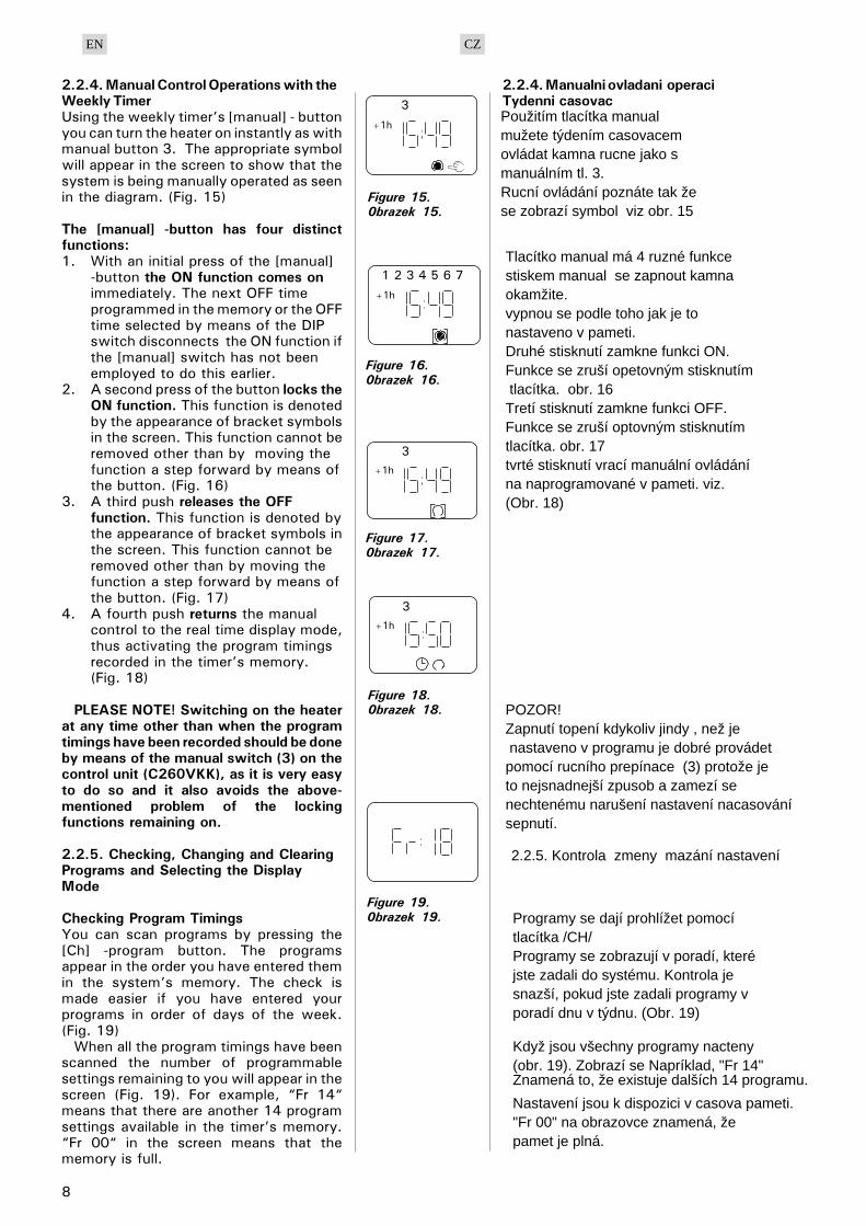
2.2.4. Manual Control Operations with theWeekly TimerUsing the weekly timer’s [manual] - buttonyou can turn the heater on instantly as withmanual button 3. The appropriate symbolwill appear in the screen to show that thesystem is being manually operated as seenin the diagram. (Fig. 15)
The [manual] -button has four distinctfunctions:1. With an initial press of the [manual]
-button the ON function comes onimmediately. The next OFF timeprogrammed in the memory or the OFFtime selected by means of the DIPswitch disconnects the ON function ifthe [manual] switch has not beenemployed to do this earlier.
2. A second press of the button locks theON function. This function is denotedby the appearance of bracket symbolsin the screen. This function cannot beremoved other than by moving thefunction a step forward by means ofthe button. (Fig. 16)
3. A third push releases the OFFfunction. This function is denoted bythe appearance of bracket symbols inthe screen. This function cannot beremoved other than by moving thefunction a step forward by means ofthe button. (Fig. 17)
4. A fourth push returns the manualcontrol to the real time display mode,thus activating the program timingsrecorded in the timer’s memory.(Fig. 18)
PLEASE NOTE! Switching on the heaterat any time other than when the programtimings have been recorded should be doneby means of the manual switch (3) on thecontrol unit (C260VKK), as it is very easyto do so and it also avoids the above-mentioned problem of the lockingfunctions remaining on.
2.2.5. Checking, Changing and ClearingPrograms and Selecting the DisplayMode
Checking Program TimingsYou can scan programs by pressing the[Ch] -program button. The programsappear in the order you have entered themin the system’s memory. The check ismade easier if you have entered yourprograms in order of days of the week.(Fig. 19)
When all the program timings have beenscanned the number of programmablesettings remaining to you will appear in thescreen (Fig. 19). For example, “Fr 14“means that there are another 14 programsettings available in the timer’s memory.“Fr 00“ in the screen means that thememory is full.
2.2.4. Manualni ovladani operaci Tydenni casovac
Figure 15.0brazek 15.
Figure 16.0brazek 16.
Figure 17.0brazek 17.
Figure 18.0brazek 18.
Figure 19.0brazek 19.
EN CZ
Použitím tlacítka manual mužete týdením casovacemovládat kamna rucne jako s manuálním tl. 3.Rucní ovládání poznáte tak že se zobrazí symbol viz obr. 15
Tlacítko manual má 4 ruzné funkcestiskem manual se zapnout kamna okamžite.vypnou se podle toho jak je to nastaveno v pameti.Druhé stisknutí zamkne funkci ON.Funkce se zruší opetovným stisknutím tlacítka. obr. 16Tretí stisknutí zamkne funkci OFF.Funkce se zruší optovným stisknutím tlacítka. obr. 17tvrté stisknutí vrací manuální ovládánína naprogramované v pameti. viz.(Obr. 18)
POZOR!Zapnutí topení kdykoliv jindy , než je nastaveno v programu je dobré provádet pomocí rucního prepínace (3) protože je to nejsnadnejší zpusob a zamezí senechtenému narušení nastavení nacasování sepnutí.
2.2.5. Kontrola zmeny mazání nastavení
Programy se dají prohlížet pomocítlacítka /CH/Programy se zobrazují v poradí, které jste zadali do systému. Kontrola je snazší, pokud jste zadali programy v poradí dnu v týdnu. (Obr. 19)
Když jsou všechny programy nacteny(obr. 19). Zobrazí se Napríklad, "Fr 14"Znamená to, že existuje dalších 14 programu.
Nastavení jsou k dispozici v casova pameti."Fr 00" na obrazovce znamená, žepamet je plná.

9
Changing Program Timings• using the [Ch] -program button scan the
screen for the program timing to bechanged. The time and day settingsthat appear in the screen can bealtered using the appropriateswitches, as explained in 2.2.3.(Fig. 20)
• finally, enter the changes using the[Ch] switch
• using the [Clock] switch return to realtime display. (Fig. 21)
Clearing Program Timings• using the [Ch] -program button scan
screen for program time/times to beremoved
• cancel hours and minutes so that theblank dashes symbol appears ( - - : 48)or ( 19 : - - ) (Fig. 22 and 23)
• finally, enter the change using the [Ch]or [clock] switch.
• The dashes will flash for a time and thedisplay will automatically return to realtime. The program is now cleared.
An efficient way of clearing all programs isto press the timer’s [reset] -button, whichwill make it necessary to start allprogramming again from the beginning.See 2.2.2.
Selecting the AM/PM Display Mode• simultaneously press the [±1h]
summer time button and the [h+]hours button; either AM or PM willappear in the screen. You can set theclock display to read 00:00 ... 11.59,but now the AM and PM symbolsindicate that the twelve-hour modehas been selected.
• Please make sure, when programmingtimings, that the AM/PM settings arecorrect.
• When there is no AM/PM display in thescreen the 24 hour clock display modeis in force.
Figure 20.0brazek 20.
Figure 21.0brazek 21.
Figure 22.0brazek 22.
Figure 23.0brazek 23.
EN CZ
Zmena v programu nacasovani
- pomocí tlacitka /CH/ budete provadet zmeny v casovani. Pro nastaveni casua dni se musite pohybovat v menu stejnejako v príkladu 2.2.3 - obr. 20.
- Pro ulozeni zmen stisknete tlacitko /CH/- stiskem tlacitka / HODINY / se dostanetezpet do realneho zobrazeni casu. ( obr. 21 )
Mazani v programu nacasovani- pomoci tlacitka /CH/ se dostanete do ovladani nacasovani. Tlacitky v menuse musite dostat v zadavani hodin a minut na 2 vodorovne carky. Viz.obr. 22 a 23.- Pro ulozeni stisknete tlacitko /CH/ nebo tlacitko / HODINY /
- pomlcky budou blikat a displej se automaticky vrati do realneho zobrazeni.Program je nyní vymazaný.
Pro smazani všech programu muzete pouzit tlacitko reset.Potom zacnete programovat od znovuViz. sekce 2.2.2.
Vyber nastaveni dopoledne/odpoledne ( AM/PM)
- tlacitkem /+1h/ si nastavujete letni a zimni casa tlacitkem / H+ / vybirate dopoledne a odpoledne, vse se zobrazi na obrazovce.
Muzete si nastavit zobrazeni na displeji pro cteni 00:00 - 11:59ale nyni symboly AM a PM indikuje12 hodinovy mod ktery lze zvolit.- Pri nastavovani si budte jisti ze nastavujete v rezimu ve kterem chcete.

10
2.3. Manual Switch (3)2.3.1. Heater On InstantlyIf you press the manual switch (3) once briefly (whilethe control unit is switched on), the heater comes onimmediately for half an hour; there is a reading of 0.5in the screen and indicator light 8 comes on (heateron). You can increase the time the heater is on bypressing the switch once for every half hourrequired. For example, six pushes of the button willturn the heater on for a duration of three hours. Youcan select a duration of up to a maximum of twelvehours. After the selection is made the screendisplays the amount of time left for the unit to remainon alternately with the temperature of the sauna andthe relevant indicator lights 6 and 7 flash insynchronised rhythm.
The programmed time left diminishes on screenautomatically at intervals of 1/10 of an hour, or everysix minutes.
2.3.2. Heater OffIf you have turned the heater on in the mannerdescribed in 2.3.1, you can switch it off before theprogrammed time has expired by pressing manualbutton 3 and holding it in for two seconds. This willturn the heater off, indicator light 8 will go out, and“OFF“ will appear in the screen.
2.4. Display Screen (4)When the control unit is in basic mode (power on) thescreen (4) displays the word “OFF“, which is thesymbol that denotes that the heater is turned off.
In function mode, when the heater has beenswitched on manually, the screen displaysnumerically both the time left for the heater to be onand the temperature of the sauna room alternately atintervals of a few seconds.
The numerals in the screen will show only thetemperature in the sauna room if the heater has beenswitched on by means of the weekly timer programor by remote control.
2.5. Temperature Regulator (5)The desired sauna temperature is set by means of thetemperature regulator (5) in the screen (4). Byturning it clockwise you increase the temperature,and by turning it anti-clockwise you lower it. Whenthe regulator is turned to the left or right the settemperature automatically becomes visible in thescreen and indicator light 6 flashes.
The maximum temperature you can set is 110°C.
2.6. Indicator Light, Red (6)When indicator light 6 is on continuously, the displayshows the temperature of the sauna. If the systemhas had to be switched on manually, the red and thegreen indicator lights come on alternately. When thered light is on the screen displays the temperature andwhen the green light is on the time left for the heaterto be on is shown.
When the temperature is being set using theregulator (5) the indicator light flashes rapidly.
2.3. Manualni owladani (3)2.3.1. Okamzite sepnuti kamen
2.3.2. Vypnuti kamen
2.5. Regulace teploty (5)
2.6. Kontrolky cerwena (6)
EN CZ
2.4. Displej (4)
Kdyz stisknete kratce tlacitko manualniho ovladani (3 ) ( kdyz je jednotka zapnuta hlavnim vypinacem ) kamna zacnou topit na pul hodinya na displeji se zobrazi 0,5 hodiny a bude svitit kontrolka 8.Vícenásobnym stisknutim si budetezvysovat doba, po kterou kamna budou topit. Napr. 6x zmacknuti je 3 hodiny. Maximálni doba je 12 hodinPo vyberu se zacne odpocitavat cas a kontrolky 6 a 7 budou blikat, dokud se nesynchronizuji.Zbyvajici cas se vzdy aktualizuje po6 minutach.
Kdyz jste kamna sepli manualne dle podle popisu 2.3.1. muzete kamna i manualnepredcasne vypnout. Kamna vypnete tim, ze podrzite tlacitko (3) po dobu 2 sekund.Tim se kamna vypnou, vypne kontrolka 8a na displeji zmizi napis OFF.
Kdyz je ovladaci jednotka v zakladnim rezimuna displeji sviti napis OFF, který ale naoznacuje ze jsou kamna vypnuty.Kdyz kamna sepnete manualne, na displeji se zobrazi v radu nekolika sekund zobrazi teplota a nastaveny cas.Cislice na displeji s teplotou v saunese zobrazi pouze tehdy pokudbudou kamna sepnuty tydennim casovacemnebo dalkovym ovladanim
Kdyz kontrolka 6 trvale sviti.Displej zobrazuje teplotu v saune.Kdyz sepnete kamna manualne,cervena a zelena kontrolka budoublikat stridave. Cervena kontrolka sviti u teplotya zelena zobrazuje odpocitavajici se cas.Kdyz se nastavuje teplota regulatorem (5)zelena kontrolka zacne rychleji blikat.
Nastaveni teploty v saune provadite pomociovladace (5) na displeji (4).Zmenu teploty provadite otacenim doleva a doprava.Pri nastavovani zelena kontrolka rychleji blika.Maximalni teplota ktera lze nastavit je 110 C.

11
2.7. Indicator Light, Green (7)When indicator light 7 is on, the screen displays thetime set for the heater to be on.
2.8. Indicator Light, Red (8)When indicator light 8 is on, the heater is turned on.
Please note! Make sure that the heater’s control unitis disconnected from the heater’s resistors when thetimer’s program timings are completed.
3. CONTROL UNIT’S INSTRUCTIONSTO ENGINEER
In accordance with the regulations in force,connecting the control and power units and thethermostat to the mains may only be carried out bya suitably authorised, professional electrician.
The person responsible for installing the control unitmust deliver, along with the heater device, thefollowing instructions for installation and use and givethe person who will be in charge of the heater and thecontrol unit the necessary training before leaving theinstalled device in his/her care!
3.1. Installation of the Control UnitC260VKKThe control unit should be mounted outside the saunaroom, in a dry area.
Please note! The control unit may not be theembedded in the wall structure. (Fig. 24)
3.1.1. Removing the Top PlateThe top plate should be removed before you mount thecontrol unit on the wall. The top plate comes off bypressing down on the locking strip at the upper edge ofthe plate, using a screwdriver, for example. The holeblanks for the connecting wires in the base plate shouldbe pierced in the places where the cables are to beconnected. (Fig. 25)
2.7. Kontrolka zelena (7)
2.8. Kontrolka cerwena (8)
3.1.
3.1.1. Demontaz predniho krytu
Figure 24. Wall-mounting the control unit
Figure 25. Location of hole blanks in the baseplate of the control unit
EN CZ
Kdyz sviti zelena kontrolka (7) na na displeji,nacasovani pro kamna je zaple.
Kdyz svizi kontrolka 8, kamna byly sepnuty.POZOR! Pÿi nastavovani ÿasovaÿe mÿjte hlavní vypínaÿvypnutý a až po celkovém nastavení mÿžeteHlavní vypínaÿ sepnout.
3. Instrukce pro montaz jednotky pro poverenou osobu.
V souladu s platnými predpisy,pripojeni ovladacich a silovych jednotek.Zapojeni veskere elektroinstalacemuze provadet pouze elektrikar s odpovydajicimi vzdelanim a povolenim.Osoba, která bude jednotku zapojovatje povinna proškolit odpovednou osobuktera se bude o spinani sauny starat.
Instalace ovladaci jednotkyOvladaci jednotka musi byt umistenazvenku sauny v suchých prostorách.POZOR!!!Jednotka nesmí byt zapustena pod uroven steny. ( Obr. 24 )
Predni kryt s musi oddelatdrive nez budeme jednotku montovat na zed. Predni kryt sundate tak ze plastove packy zatlacite dovnitr a predni krytoddelate.

12
3.1.2. Fastening the Device to the WallThere are holes for three (3) screws in the base plate,for fastening the unit to the wall. If necessary, drill ahole in the wooden wall using a 2.5 mm bit. If you haveto fasten the device to a stone wall, drill a 6 mm holefor a Rawlplug to its complete length. Hit the Rawlpluginto the hole and screw fastening screw 1 into placewith a screwdriver, until approx. 7 mm of the screw-head is left visible. The electric cables entering andexiting the control unit should be passed through theopen holes. The device can be suspended by the upperscrew when you have ensured that the screw-head islocked into the narrow notch of the hole in the baseplate. Holding the device in the upright position, markthe locations for the two lower fastening screws (2 and3) and follow the same procedure, except that thesescrews should be screwed tightly in as far as they go.(Fig. 26)
3.1.2. Wandbefestigung
Figure 26. Fastening the device to the wall
3.1.3. Electrical ConnectionsDiagram 27 shows how the connections are made.
3.1.3. Elektricke schema
Figure 27 Electrical connections0brazek 27
EN CZ
Jednotku na zed prichytte dle obrazku 26.
Elektricke schema
Poj
istk
y
Tep
lotn
i cid
lo
Indi
kacn
i sve
tlo

13
3.1.4. Altering the Basic Settings of the Control UnitThe maximum times you can set the heater to come onfrom the control unit are : 6 h, 12 h, 18 h orcontinuously. The settings are carried out by means ofDIP switches. The factory pre-set maximum for theheater to be on is twelve hours.
The factory pre-set arrangement may be alteredusing the two switch lobes on the left side of the DIPswitch, as follows (Fig. 28):
Using DIP switch 3, you can select which controloption to use for turning the heater on: the weekly timer(Weektimer) or remote control. To select control byweekly timer, set the switch to the ON position, orchoose remote control by setting the switch to the OFFposition.
Please note! You must always leave DIP switch 4 setto the ON position since the OFF position is reserved fora special function.
3.1.5. Use of the Control Unit by Remote ControlThe control unit can be operated by remote control,either by means of the ON/OFF function or byelectrical impulses. The remote control device musthave contact surfaces that are good electricalconductors (e.g. electrical relay or switch). Theconnection can also be realised with electronicswitch components. (Fig. 29)
Please note! The functions are limited by a 6-hourinterval. This prevents the heater from being switchedon if less than 6 hours has passed since the previoustime the heater was switched OFF.
If you try to switch the heater on during this interval(6 h), the screen will display ’SAF’.a) the connection controlling the ON/OFF function ismade at positions 11 and 12 in the connector strip. TheON/OFF function is obtained, for example, by means ofthe normal ON/OFF switch. The control works by low-tension “short-circuiting“ of the control line, so thatthe cross-section of the wire in the control line cablesis sufficient at 0,5 mm2.
In ON/OFF mode the control unit keeps the heater onas long as the control switch’s contact point is closed.If the pre-set time for the heater to be on has not yetshut off power to the heater, opening the controlswitch’s contact point turns the heater offimmediately.b) For the electrical impulse function to work thecontrol switch’s contact points only have to makecontact with each other once. The ON functionstarts from studs 9 and 10 in the connector strip andthe OFF function from studs 7 and 8. The controlworks by low tension as with the ON/OFF function.If the pre-set time for the heater to be on has not yetshut off power to the heater, momentarily closingthe control switch’s contact point in impulsefunction turns the heater off immediately.Please note! The engineer must give the customerproper instructions on the functions of the remotecontrol system!
3.1.6. Indicator LampThe control unit shows heater setting times by meansof an indicator lamp (24VDC), which comes on in theplace from which the heater is remotely controlled. Theindicator lamp comes on when the heater is on.
3.1.4. Alternativni nastaveni v ovladacim panelu
3.1.5. Dalkove ovladani kamen
3.1.6. Kontrolky pri dalkovem ovladani
EN CZ
Maximalni cas ktery lze nastavit pro provoz kamen je 5h, 12h, 18h nebo nepretrzity provoz.Tyto hodnoty nastavujete pomoci DIP prepinace.Tovarni nastaveni je na 12 h.Tovarni nastaveni muzete menit pomoci 2 prepinacu vlevo.viz obr. 28.Pomoci tretiho prepinace zlevavybirate mezi tydennim rezimem nebo dalkovym ovladanim. 3 - ON - tydenni casovac, 3 - OFF - Dalkove ovladani.
Ovladani kamen lze i dalkove pomoci, funkci ON / OFFelektrickychych zmen. Dalkove ovladani musi pracovat pomoci rele nebo prepinacu, nebo jinehoelektrickeho prepinace. ( Obr. 29 )Prosim pozor!! Funkce jsou omezeny na 6 hodinove intervaly.Je to preventivni opatreniKamna nejdou zapnout dokud neprobehne6 hodinovy interval od vypnuti kamen.Kdyz zkusite kamna sepnout drive nezvyprsi 6 hodinovy interval.na displeji se zobrazi napis SAF.a) Pripojeni kontroluje funkci ON /OFFna pozicich svorkovnice 11 a 12.Funkce ON / OFF ziskava ovladaci signalnapr. z normalniho manualniho prepinace.Kontrolni prace provadejte s nizkym napetim a s prumerem vodice 0,5mm2.V ON / OFF rezimu jednotka udrzuje kamna sepnutytak dlouho dokud je prinaci kontakt zavreny.V prednastavenem casu pro sepnuti kamen se kamna jeste nevypnou. Jakmile se vsak prepinaci kontakt pohne, kamna se okamzite vypnou.b)
Ridici jednotka zobrazuje nastaveni casu kamenpomoci kontrolek ( 24V DC ), ktere se zobrazujiz miste kde jsou kamna dalkove ovladany.Kontrolky zobrazuji kdyz kamna topi.
Upozornění! DIP přepínač 4 vždy nechte v pozici ON, poziceOFF je rezervována pro speciální přídavné funkce.
Řídící jednotka C260 může být ovládána dálkově, buď pomocíON/OFF funkce (např. spínač, relé), či impulsním snímáním (např. zvonková tlačítka).Dálkové ovládání pracuje s nízkým napětím, zvolte kabel o průměru minimálně 0,5 mm2. Schéma zapojení viz obr. 29.
Upozornění! Funkčnost je limitována 6h bezpečnostním intervalem vypnutí topidla. Po vypnutí topidla ho dovolí znovu zapnout až po 6 hodin trvající pauze. Pokud se pokusíte zapnout topidlo dříve, než uběhne 6 hodin od vypnutí, na displeji regulace se objeví nápis "SAF".
na konektoru se používají svorky 11 a 12 (viz obr. 29). Topidlo je zapnuté tak dlouho, dokud je sepnutý kontakt na svorkách 11 a 12, nebo do ukončení přednastaveného časového intervalu.
Pokud odpojíte kontakt na svorkách v průběhu přednastave-ného časového intervalu, topidlo se ihned vypne.
A)ON/OFF spínání:
B)Impulzní spínání:
dvě zvonková (impulzní) tlačítka-Kontakt Vypnutí (OFF) na svorkách 7 a 8-Kontakt Zapnutí (ON) na svorkách 9 a 10-Topidlo je zapnuté podle přednastaveného časového intervalu. Pokud stisknete kontakt OFF v průběhu přednastaveného časového intervalu, topidlo se ihned vypne.
Upozornění! Autorizovaný technik zapojující dálkové ovládání musí zákazníka upozornit, jakým způsobem je toto ovládání provedeno!

14
Figure 29. External connectionsobrazek 29. Externi zapoieniFigure 28. Setting the alternative of operating times
obrazek 28. nastaveni a zmeni tovarniho nastaveni
Please note! The power of the indicator lamp may notbe greater than 1 W.
Finally, fix the control unit’s top plate in place.
3.2. Installing the Thermostat’s Sensor BoxAs the location of the sensor box depends on the powerof the heater, that location is shown in theaccompanying diagrams only in the case of high-powered heaters of between 20 and 33 kW. (Fig. 30)
The cable enclosed with the thermostat is made ofsilicon and can withstand temperatures of up to+170 °C. The cable can be extended with lowertemperature cable having a corresponding cross-section, as long as you ensure that after theconnection has been made the temperature to thecable does not rise above +80 °C. The thermostat’sconnecting cables must be connected to locations 3,4, 5 and 6 in the control unit’s connector strip inaccordance with the relevant connections diagram(Fig. 29). If the cables in the thermostat componentsbecome disconnected one of the following errormessages will appear in the display screen: “Er1“,“Er2“ or “Er3“. See 1.
3.2. Instalace teplotniho cidla
Figure 30. Installation of control unit (C260) sensor box and of the heaters L20-L33obrazek 30. Instalace cidla pro kamna L20-L33
EN CZ
Umisteni cidla zalezi na vykonu kamen.Viz. obr. 30 kde jsou vzdy hodnoty pro kamna 20 - 26 KW a pro kamna 30 - 36 KW.Kabel k cidlu je silikonovy a snasi teplotyaz +170 C. Prodlouzit kabel lze, nejvhodnejsije taky silikonovy kabel.Kabel k cidlu musi byt zapojen podle nakresu do svorkovnice3,4,5 a 6. Viz. obr. 29. Kdyz je kabel nebo cidlo nefunkcni, na displeji sezobrazi chybove hlasky ER1, ER2 nebo ER3.
na zed na zed na strop
cidlo cidlo cidlo
Indikacni kontrolka(max 1w)
Teplotni cidlo

15
3.3. Installing the Power Unit C260KThe power unit should be mounted outside the sauna room,in a dry area, at a height of approx. 170cm from the floor.Please note! The control unit may notbe the embedded in the wallstructure. (Fig. 31)
The power unit’s contactors andfuses enable electric power to flowalong the heater’s two power cables.The connection is shown in thediagram.(Fig. 32)C260-20K1: contactor 63AK2 and K3:contactor 25A forpower groups G1 and G2F1 and F2: fuse 16AF3: fuse 6A for C260VKKC260-34K1: contactor 63AK2 and K1:contactor 25A for power groups G1 and G2F1 and F2: fuse 25AF3: fuse 6A for C260VKK
3.3.1. Removing the Top PlateBefore installing the power unit, remove the upper partof the box with its top plate from the metal base byunscrewing the fastening screws (4 pcs). (Fig. 33)
3.3.2. Fastening the Device to the WallThe power unit base should be screwed to the wall (fourscrews) near the control unit. Pierce the hole bands forthe connection wires which will be found at the top orbottom edge of the base (Fig. 34). The close proximityof the units ensures that the connecting leads betweenthe two are short. The ends of the cables are passedinto the box.
3.3.3. Electrical connectionsThe electrical connections are made in accordancewith the connections diagram (Fig. 27).
3.3.1. Demontaz predniho krytu silove casti
3.3.2. Prichyceni silove casti na zed
3.3.3. Elektricke schema
Fig. 31. Installation of the control unit on a wall
obr. 31. Instalace silove casti
EN CZ
3.3. Instalace silove casti C260K
Silova cast nesmi byt umistena uvnitr sauny,
vzdy zvenku sauny v suchem miste cca 170 cm
od zeme.
POZOR!! Silova cast nesmi byt zapustena ve stene.
( Obr. 31 )
Rozvadece a pojistky zasobuji elektrinou kamna pomoci
2 kabelu. Zapojeni je na obr. 32.
C260-20
K1: Jistice 63A pro
obe skupiny G1 a G2
F1 a F2 - 16A
F3: pojistky 6A pro C260VKKC260-34
K1: Jistice 63A pro
obe skupiny G1 a G2
F1 a F2 - 25A
F3: pojistky 6A pro C260VKK
Pred demontazi predni casti silove skrine musite odsroubovat 4 sroubky z cela.( Obr. 33 )
Montaz provadejte podle nakresu 34.
Elektricke zapojeni najdete v obr. 27.

16
Figure 32. Internal connections of the power unitobrazek 32. vnitrni zapoieno silove casti
Figure 33.Removing the top plateobrazek 33.demontaz predniho dilu
Figure 34.Wall-mounting thepower unitobrazek 34.umisteni na zed
Figure 35. Reset button foroverheating limiterobrazek 35. resetovani teplotni ochrana
TO CONTROL UNITZUM STEUEREINHEIT
MAX 22 kWMAX 34 kWPOWER UNIT
K1: 63AK2, K3: 25ACONTACTORS
F1, F2 (16A)F1, F2 (25A):FUSES
F1 F2 F1 F2 F1 F2 F3
A1 A1K3K2
Group ISkupina 1
A2
Group IISkup 2
A2
1 3 5 7 1 3 5 7
2 4 6 8 2 4 6 8
1 3 5 7
2 4 6 8
A1K1A2
1 2 3 4 5 6 7 8 9 1011 13
12
N L K1K2K3
GROUP IGRUPPE I
GROUP IIGRUPPE II
N L1N L2 L3L1L2 L3L1 L2 L3N
ELECTRIC CENTREELEKTROZENTRALE
400V 3N~
N
6A
EN CZ
Instalace teplotniho cidla
PojistkySilova cast Svorkovnice