
C2063 - UH230-430 R05 MANUAL(R)
81
1 R07 ET xtreme ® STANDARD TAPE HEAD Serial Numbers UH230T, UH430T
Transcript of C2063 - UH230-430 R05 MANUAL(R)

1 R07
ET xtreme® STANDARD TAPE HEAD
Serial Numbers UH230T, UH430T

2 R07

3 R07
TABLE OF CONTENTS Section 1 HHHTUTUTUTable Of ContentsUUUTTTHHH--------------------------------------------- 3 Section 2 HHHTUTUTUTechnical AssistanceUUUTTTHHH----------------------------------------- 4 Section 3 HHHTUTUTUWarrantyUUUTTT HHH--------------------------------------------------------- 5 Section 4 HHHTUTUTUDescription Of Tape HeadUUUTTT HHH---------------------------------- 6 Section 5 HHHTUTUTUSafety IssuesUUUTTTHHH--------------------------------------------------- 7 Section 6 HHHTUTUTUSpecifications UUUTTTHHH--------------------------------------------------- 10 HHHTUTUTUTape Head DimensionsUUUTTTHHH-------------------------------------- 10 HHHTUTUTUTape Head ComponentsUUUTTTHHH------------------------------------- 11
Operating Conditions-------------------------------------------12 HTUTape Head Specifications UUUTTTHHH------------------------------------ 12 HHHTUTUTUInstallation In Other Machinery UUUTTTHHH----------------------------- 13 Section 7 HHHTUTUTUSet Up ProceduresUUUTTTHHH-------------------------------------------- 14
Receiving and Handling---------------------------------------14 HHHTUTUTU Mounting AdaptersUUUTTTHHH-------------------------------------------- 15 HHHTUTUTUTape LoadingUUUTTT HHH--------------------------------------------------- 16 HHHTUTUT UTape ThreadingUUUTTTHHH------------------------------------------------ 17
Tape Centering------------------------------------------------- 19
HHHTUTUT UTape Leg Length AdjustmentUUUTTTHHH------------------------------ 21 HHHTUTUTU One Way Clutched Roller AdjustmentUUUTTTHHH------------------- 22 HHHTUTUTU Main Spring AdjustmentUUUTTTHHH------------------------------------- 22 Low Profile Setting--------------------------------------------- 24 Knife Arm Spring Adjustment------------------------------- 24 HHHSection 8 HHHTUTUTUTroubleshootingUUUTTTHHH------------------------------------------------ 25 Section 9 HHHTUTUTURecommended Spare Parts ListUUUTTTHHH--------------------------- 28 Section 10 HHHTUTUTUPreventive MaintenanceUUUTTT HHH------------------------------------- 30 HHHTUTUTUKnife Blade ReplacementUUUTTTHHH----------------------------------- 30 HHHTUTUTUOiler Pad LubricationUUUTTTHHH----------------------------------------- 31 HHHTUTUTUUrethane Tucking Roller ReplacementUUUTTTHHH------------------ 32HHHTUTUTU
Spring ReplacementsUUUTTTHHH---------------------------------------- 33 HHHTUTUTUWipe Down Brush ReplacementUUUTTTHHH-------------------------- 40 HHHTUTUTU Schedule Of Preventive MaintenanceUUUTTTHHH------------------- 41 Section 11 HHHTUTUTUAppendix A-Illustrations And Parts ListsUUUTTT HHH---------------- 42 HHH

4 R07
TECHNICAL ASSISTANCE
Technical Support This is the Interpack Model ET xtreme® Series Tape Head you ordered. It has been set up and tested in our factory with Intertape brand tapes. If any problems occur when setting up or operating this equipment, please contact the authorized distributor from where you purchased this item. If contact with the authorized distributor is not possible, Interpack Technical Support is available. Should you need to contact Interpack Technical Support, please have the Tape Head’s model number and serial number on hand. This information can be found on the label affixed to the Cover Frame of the Tape Head. Interpack Technical Support is available during normal business hours 8:30 a.m. to 5:00 p.m. (Eastern Time). Tel: 1-800-474-8273 Option 3 If you have a technical question that does not require an immediate response, you may contact Interpack by fax. Fax: 1-800-462-1293 Technical support may also be contacted via email at the address below: Email: [email protected] Replacement Parts Order parts by part number, item description and quantity required. Replacement parts are available from your Authorized Interpack Distributor exclusively. Should you require assistance selecting the correct part, you may call: Intertape Polymer Group Interpack Machinery Tel: 1-800-474-8273 Option 3 Fax: 1-800-462-1293 MODEL: SERIAL NUMBER: DISTRIBUTOR PURCHASED FROM: DATE OF PURCHASE:

5 R07
WARRANTY EQUIPMENT WARRANTY AND LIMITED REMEDY: The following warranty is made in lieu of all other warranties, express or implied, including, but not limited to, the implied warranty of merchantability, the implied warranty of fitness for a particular purpose, and any implied warranty arising out of a course of dealing, a custom or usage of trade: Intertape sells its Interpack Tape Heads, Case Tapers and Case Erectors with the following warranties:
1. The ET xtreme® Tape Heads' blades, springs and tucking rollers will be free from all defects for a period of ninety (90) days.
2. All other ET xtreme® Tape Head parts will be free from all defects for one (1) year after delivery. 3. Water Activated Tapers’ blades and brushes will be free from defects for ninety (90) days after
delivery. 4. Drive Belts will be free from defects for ninety (90) days after delivery. 5. The Gear Motors will be free from defects for one (1) year after delivery. 6. All other components will be free from defects for one (1) year after delivery.
If any part is proven defective within its warranty period, then the exclusive remedy and Intertape's and the seller's sole obligation shall be, at Intertype’s option, to repair or replace the part, provided the defective part is returned immediately to Intertape's factory or an authorized service station designated by Intertape. A part will be presumed to have become defective after its warranty period unless the part is received or Intertape is notified of the problem no later than five (5) calendar days after the warranty period. If Intertape is unable to repair or replace the part within a reasonable time, then Intertape, at its option, will replace the equipment or refund the purchase price. Intertape shall have no obligation to install the repaired or replacement part. Intertape shall have no obligation to provide or pay for the labor required to install the repaired or replacement part. Intertape shall have no obligation to repair or replace (1) those parts failing due to: operator misuse, carelessness, or due to any accidental cause other than equipment failure, or (2) parts.
1. Failure or damage is due to misapplication, lack of proper maintenance, abuse, improper installation or abnormal conditions such as temperature, moisture, dirt or corrosive matter, etc.
2. Failure due to inadequate cleaning, improper operating environment, improper utilities or operator error.
3. Failure due to operations above the rated capacities, or in any other improper manner, either intentional or otherwise.
4. Failure is due to equipment, which has been altered by anyone other than an authorized representative of Intertape Polymer Group.
5. Failure is due to an attempt by the purchaser to correct alleged defective equipment. In this event the purchaser is responsible for all expenses incurred.
LIMITATION OF LIABILITY: Intertape and seller shall not be liable for direct, indirect, special, incidental or consequential damages based upon breach of warranty, breach of contract, negligence, strict liability or any other legal theory. The foregoing Equipment Warranty and Limited Remedy and Limitation of Liability may be changed only by written agreement signed by authorized officers of Intertape and seller.

6 R07
DESCRIPTION OF TAPE HEAD
Figure 4-1
The Intertape ET xtreme® Family of Tape Heads are designed to apply Intertape brand pressure sensitive carton sealing tape to the top and bottom center seam of regular slotted corrugated cartons.
The ET xtreme® can be configured into all Interpack case sealers.
This ET xtreme® is also designed to upgrade most competitive case sealers. Interpack can provide a variety of adaptor kits to install this tape head into most case sealers.

7 R07
SAFETY ISSUES
There is a safety label used on all Interpack Tape Heads. This label is placed on the Tape Head knife guard to warn operators and service personnel of the sharp cutting edge of the blade. Please read the label and the following safety precautions before using the Tape Head.
Read this manual for other important safety operating and service information.
Only trained personnel are to operate and service Tape Head.
Wear safety glasses.
Shut off power to machine before adjusting.
Unplug electrical power before servicing.
All covers and guards must be in place before operating.
Stay clear of moving parts which can shear and cut.
Never operate the Tape Heads with the Knife Guard removed.
Turn electrical supply off before servicing the Tape Heads, including tape loading and threading.
Note: Should any of the safety labels placed on the Tape Head be damaged or destroyed, replacements are available.

8 R07
SAFETY ISSUES
The illustrated label shown in Figure 5-1 is attached to the Knife Guard. The label warns operators and service personnel of the very sharp blade. The guard shall only be removed when the torsion spring or the guard itself are being replaced. Should the tape head be operated without blade guard, user voids all warranty implied, the manufacturer bears no responsibility for the consequences. Tape head shall never be serviced while mounted in a machine.
Figure 5-1
Label on Figure 5-2 is visible on carton sealing machine.
Figure 5-2
While the tape head is processing cartons, or it is in motion, keep your hands away (Figure 5-3).
Figure 5-3

9 R07
SAFETY ISSUES
The illustrated label shown in Figure 5-4 is attached to the operator side plate of each tape head. The label provides operators and service personnel the proper method of threading a new roll of tape through the tape head. More detailed information is provided in the “Set Up Procedures” portion of this manual. Turn air and electrical supplies off before servicing the tape heads.
Figure 5-4

10 R07
SPECIFICATIONS
UUUTape Head Dimensions
Figure 6-1

11 R07
SPECIFICATIONS UUU
Tape Head Components
Figure 6-2

12 R07
SPECIFICATIONS UUU
Operating Conditions
Use in a dry, relatively clean environment at 40º to 105º F (5º to 40º C) with clean, dry cartons.
Note: The ET xtreme® Standard Tape Head CAN be washed down with mild Detergent (soap).
UUUTape Head Specifications
1) General Use Intertape brand Pressure Sensitive Sealing Tape.
2) Tape Width For ET xtreme® 2” (48mm) models:
1 ½ to 2 inch wide tape (36 to 48 mm). For ET xtreme® 3” (72mm) models: 2 ½ to 3 inch wide tape (60 to 72mm).
3) Tape Roll Diameter Maximum of 16 inches (405 mm) on a 3-inch (76.86 mm) diameter core. (Accommodates all Intertape brand film tape machine roll lengths).
4) Tape Application Leg Length – Standard 2 ¾” ± ⅛” (70 ± 3mm).
5) Tape Application Leg Length – Optional The tape leg length can be adjusted from: 2 inches to 3 inches (50 mm to 76 mm). 6) Tape Head Weight
ET xtreme® 2” Tape Head weighs 9 lbs. (4 kg.). ET xtreme® 3” Tape Head weighs 9.9 lbs. (4.5 kg.).
7) Operating Speed For use with line speeds up to 140 ft/min maximum.
UU PLEASE NOTEUUU: A stronger main spring may be necessary to process cases at 140 ft/ min. Void filled cases should not be processed with the stronger main spring.

13 R07
SPECIFICATIONS
UUUInstallation of ET xtreme® tape heads in Other Machinery This tape head can be used to upgrade case sealers provided by other manufacturers. It can be mounted in upper, lower, or horizontal positions. For installation of tape heads on non–IPG branded machines, contact your distributor or technical support (see pg. 4) for required mounting adaptors. For expedited service, please have machine model and serial number on hand.
1) The case must be positively propelled through the case sealer taking into account any void fills, overfills, stability factors or weight factors.
2) Verify the case sizes which will be processed through the case sealer. Installing Interpack ET xtreme® tape heads to process very short cases may cause the tape heads to collide with each other.
3) If a flight bar or lug drive system propels the case, ensure that these devices provide proper clearance and do not contact any portion of the tape head.
4) Ascertain that the proper adapter kits have been ordered and received with the tape head.

14 R07
SET-UP PROCEDURES
UUUReceiving and Handling All contents must be verified upon reception. The following items are included with each tape head.
DESCRIPTION UH 230T 2” WIDE
UH 430T 3” WIDE
Main Tape Head assembly 1 1
SS SHCS M6 - 1 x 8 (part no. UF3170) 4 4
Mounting adaptors (part no. UPH0283) 4 -
Mounting adaptors (part no. UPH3881) 4 4
Mounting adaptors (part no. UPH0256) - 4
Mounting adaptors (part no. UPH0284) 4 -
Mounting adaptors (part no. UPH3883) 4 -
SS Main spring (part no. UPH1091) 1 1
SS Ext. Main spring (part no. UPH0910) 1 1
Knife arm spring (part no. UPH7427) 1 1
Operational manual & parts list 1 1
Note: After unpacking the Tape Head, look for any damage that may have occurred during shipping. Should the Tape Head be damaged, file a claim with the transport company and notify your Intertape representative.

15 R07
SET-UP PROCEDURES
WARNING! TURN OFF ELECTRICAL POWER SUPPLY AND DISCONNECT THE POWER CORD FROM THE ELECTRICAL SUPPLY BEFORE BEGINNING TO WORK ON THE TAPE HEADS OR TO LOAD TAPE. IF POWER CORDS ARE NOT DISCONNECTED, SEVERE INJURY TO PERSONNEL COULD RESULT.
UUUMounting Adapters ET xtreme® Tape Heads require Mounting Adapter Hardware to install in any case sealer or case erector. If your Tape Heads are pre-installed in your Interpack case sealer or case erector, you do not need to follow any instructions from this section. If your tape heads will be installed in any other brand machinery, please review these general guidelines plus any additional instructions included with your ET xtreme® tape head.
Location Of Mounting Adapter Holes
Cover Plate Side
Figure 7-1
Main Plate Side
Figure 7-2 Examples Of Mounting Hardware There are four (4) mounting holes on the main and cover plates of the tape head. These are used to install various mounting adaptors. Examples of these mounting adapters are:
1. Internal and external threaded nuts. 2. Mounting Bars. 3. Threaded Spacers.
Figure 7-3

16 R07
SET-UP PROCEDURES
UUTape Loading The ET xtreme® is designed to accommodate “2 inch” (48mm) wide tape rolls, while the ET xtreme®/3" accommodates “3 inch” (72mm) wide rolls.
1. Place the tape head onto a sturdy, flat surface. 2. Move the Peel Off Roller away from the mandrel. if you need help to keep Peel Off
arm away, latch the friction washer temporarily. 3. Push the roll of tape onto the mandrel with the adhesive side facing away from the
peel Off Roller (refer to Threading Diagram on Figure 5-4 under Tape Threading section in this manual) until the core sits against the mandrel flange. The hooked red sprag should latch onto the tape core. While removing the tape, this should be pressed down to free the tape.
4. Loosen friction washer and turn the Peel Off Arm against the tape roll.
Figure 7-4
Adhesive Side Peel Off Roller
Tape Roll
Friction Washer

17 R07
SET-UP PROCEDURES
WARNING! THE KNIFE CONTAINED IN THE TAPE HEAD IS EXTREMELY SHARP. USE CAUTION WHEN REMOVING THE BLADE GUARD AND THREADING THE TAPE TO AVOID PERSONNEL INJURY.
Tape Threading Preparation
Threading the tape in the Tape Head does not require any special tools. Pull approximately twelve (12) inches of tape from the roll and fold in half lengthwise, adhesive side to adhesive side. This allows you to thread the tape without it adhering to the guide and clutch rollers inside the Tape Head.
Figure 7-5

18 R07
SET-UP PROCEDURES
Refer to Figures 7-6 & 7-7 for visual assistance of the following tape threading.
1. First thread the tape tail over the Peel Off Roller. 2. Continue to thread the tape over and around the “knurled” Clutch Roller. 3. Then pass the tape up and over the “smooth” Guide Roller. 4. Continue threading the tape over and behind the final “knurled” Guide Rollers. 5. Thread the tape through the cut-out provided in the Tape Guide Shoe and pull the tape
through to the front of the Application Roller, ensuring that the tape is retained in the tape guide shoe.
6. Cut off the folded tape. 7. Replace the Tape Head to its initial position in the machine.
Adhesive Side
Guide Roller Clutch
Roller
Application Roller Figure 7-6 Figure 7-7

19 R07
SET-UP PROCEDURES
UUTape Centring
If the tape is not centered as it travels through the tape shoe guide, the tape mandrel can be adjusted in or out to correct this.
Loosen the M18 inverse jam nut on the rear of the mandrel as shown in Figure 7-8. with a 10 mm allen key. (Turn it counterclockwise to unlock it.)
Adjust the shaft in or out as required using a flathead screwdriver as illustrated in Figure 7-9. When the tape is centered, tighten the jam nut.
Note: One full turn will result in 1mm tape deplacement.
Figure 7-9
Figure 7-8
10mm HEX KEY
JAM NUT

20 R07
SPRAG
NOTCH
SET-UP PROCEDURES
UUUCentring 36mm(1 ½”) & 60mm(2 ½”) Tapes If the tape is not a standard size, the tape mandrel hub will need a Spacer Ring to center the tape. Spacer Ring part # is UPH7435. Use the Spacer rings for the 36mm(1 ½”) tape on a 2” mandrel hub and the 60mm(2 ½”) tape on a 3” mandrel hub.
1. Position the Spacer Ring in front of the mandrel hub in a way that the notches of the Spacer Ring will align with the Sprags on the mandrel hub as shown in Figure 7-10.
2. Push the Spacer Ring all the way on the mandrel hub as shown in Figure 7-11. 3. It will take a second Spacer Ring to sandwich the tape roll into position.
Figure 7-11 Figure 7-10
SPACER RING

21 R07
SET-UP PROCEDURES
UUUTape Leg Length Adjustment For safe sealing, the tape leg length has been factory set at 2 ¾ inches (70 mm). However, the tape leg length can be shortened or increased.
Front Tape Leg
To adjust the tape leg length on the front panel of the box, refer to Figure 7-12 of the clutch assembly. Facing the rear main frame, loosen the two (2) M6 Flat Head Cap Screws using a 4 mm hexagonal key. Move the clutch assembly to bring it towards the minus (-) sign stamped on the plate for a shorter tape leg. Conversely, bring the M6 screw towards the plus (+) sign for a longer tape leg. Re-tighten both M6 Flat Head Cap Screws.
To adjust the tape leg length on the trailing end of the box, both knife arm extension brackets must be re-positioned in unison. Unscrew the three (3) M4 Screws on each knife arm extension using a 2.5 mm hexagonal key. For a UUUShorter Tape LegUUU, bring the knife arm towards the UUUfrontUUU of the tape head. Conversely, for a UUULonger Tape LegUUU, bring the knife arm Extension towards the UUUrearUUU of the tape head. Replace the three (3) M4 screws on each knife arm extension and tighten. Once you obtained the required rear tape leg, secure the screws with Loctatie 222 (purple) threading agent. Please note that the rear tape leg is dependent on line speed.
Figure 7-12
Figure 7-13
Rear Tape Leg
CLUTCH ASSEMBLY
M6 SCREWS
REAR
FRONT

22 R07
SET-UP PROCEDURES Clutch Roller Adjustment The one-way clutch roller assures that the tape does not go backwards any time during dispensing, further more it is a tool in achieving correct front tape leg length. Different quality tapes have different adhesives and release coats. This has an effect on the dispensing, e.g. very “sticky” tapes are peeling-off with higher resistance, so they will need minimal tension on the clutch roller. Tapes that unwind easily may need more tension on the clutch roller to achieve uniform front tape leg length during sealing.
Main Spring Adjustment
1.) To decrease the clutch roller’s tension, turn the
M6 friction nut at the end of roller counterclockwise, it requires a 10 mm wrench. Do not loosen to the point that the roller could be moved laterally on the shaft.
2.) To increase the clutch roller’s tension one needs
to turn the M6 friction nut clockwise. Make tiny increments (less than eighths of a turn) at a time and check the sealing results before going any further. Once the disc spring has been over squeezed it may lose its properties. To avoid this eventuality, pay attention.
The main spring retainers are set at the factory for the most common applications. The top tape head will need lighter springs, UPH0910 or UPH0911, while the bottom positioned tape head will need heavier springs, UPH1091. The ET-X 3-inch tape heads can run up to 140 ft/min line speed, the 2-inch version up to 150 ft/min line speed. In applications one might have normal cases, over filled cases, void filled cases, flimsy corrugated boxes, stiff double fluted cases. The speed and the nature of the box will determine the best main spring setting. Typically, the higher the line speed the more tension one requires from the main spring. To increase the rollers’ pressure we have the following techniques to choose from in order of ease: Option 1: If one needs a little bit more (~15%) pressure on the application rollers and have a stainless steel spring mounted on the tape head, may change the spring for the music wire version. (UPH0911 for top tape head and UPH1091 for bottom tape head)
MAIN SPRING
Figure 8-1
M6 FRICTION
NUT

23 R07
FRONT OF T.H.
M5 FHCS
SET-UP PROCEDURES
Option 2: To change the rollers’ pressure one can move the spring retainer’s position on the cover frame. Move the M5 FHCS towards the front of the tape head to increase the pressure or towards the rear to decrease the pressure. See Figure 8-2.
Option 3: When the loop is still persevering in the rear tape leg, one can raise the spring retainers position on the rear arm. This will increase the torque on the rear arm. Loosen the M6 FHCS on the rear arm and move a position up, farther away from the pivot axis.
2 1
3
The previously listed 3 options may need to be employed in combination to get the best result. For instance, to get the 3-inch tape head in top tape head mode at 120 ft/min line speed make the following set up, refer to Figure 8-3. Put the M6 FHCS (item 1) on rear arm on the second position from pivot shaft. Put the M6 FHCS (Item 3) on the Cover Frame closest to the rear end position. Take the heavy stainless steel main spring UPH1091 (item 2) and attach it to these spring retainer points. A reminder to tone down unrealistic expectations; boxes without stamina cannot be processed at high speeds!
Figure 8-2
Figure 8-3
M6 FHCS
REAR OF T.H.

24 R07
SET-UP PROCEDURES Low Profile Setting When processing 4”- 6” high cases, one might want to set the tape head into low profile position. In this case the application rollers will extend to 2”. To achive these 2” tape legs, the rear bumpers have to be moved on the main frame and cover frame in synch. With the help of a ¾” wrench and a 3 mm allen key loosen the M5 FHCS holding the bumpers. Reposition them into the third notch in the middle, - see figure 8-4. Making the arms extending shorter than 2” is not recommended. Also refer to page 21 for tape leg settings.
M5 FHCS
Knife Arm Spring Adjustment 1. To increase the force, using a 10mm open end wrench, turn the 6mm nylon lock nut clockwise until
desired pressure achieved.
2. To decrease the force, using a 10mm open end wrench turn the nylon lock nut counterclockwise, so that the pressure on top flaps is reduced, but it still cuts the tape.
Figure 8-4
M6 NUT 10mm
WRENCH

25 R07
TROUBLESHOOTING ET xtreme® Tape Heads are fabricated with high quality components that provide trouble-free operation for a long period of time. However, should a problem occur, we recommend that you consult the following table. If the problem you encounter is not discussed in this table, call Interpack Technical Support. (see page 2 of this document).
TROUBLE POSSIBLE CAUSES SOLUTIONS
Tape does not cut cleanly.
Blade needs to be replaced. Knife compression spring too weak or broken. Increase pressure on compression spring in repuslvie pivot assembly. One way clutch roller needs adjusting.
Replace blade. Refer to preventive maintenance section for details. Replace Knife Arm Spring. Refer to preventive maintenance section for details. Slightly increase the tension on the one way clutched roller.
Front tape leg too short.
Generally, too much tension on the application of the tape. Tape threaded incorrectly. Tape leg length misadjusted.
Follow corrective action in “Tape Flagging” section below. Check for proper tape threading against threading diagram on side plate of tape head. Re-set front tape leg length.
Tape Leg UUUin the tape head UUU folds up on itself.
Strong air circulation (fan) is in the vicinity. Spring loaded finger is out of position.
Redirect airflow away from the tape head. Check compression spring mobility.
Rear tape leg does not fit tight on the box. (ripple effect).
Main spring is not strong enough.
Change for the stronger main spring. (Part no. UPH1090).

26 R07
TROUBLESHOOTING, CONTINUED
TROUBLE POSSIBLE CAUSES SOLUTIONS
“Tape Flagging” or folding on itself on the trailing tape leg.
Generally, too much tension on the application of the tape. Follow steps below. Applying urethane rollers, delrin guide rollers, knurled metal rollers should spin freely. Check for any adhesive migration or build up. Mandrel does not spin freely even after tension is reduced. Too much one way clutch roller tension. Tape unwind is difficult. Cutter blade is dull.
Remove any adhesive build up with silicon spray. Disassemble any non free spinning rollers and remove any adhesive build up on shafts. Disassemble mandrel assembly and check debris. Decrease clutch roller tension. Check freedom of Peel Off Roller. Replace blade and oil blade pad.

27 R07
TROUBLESHOOTING, CONTINUED
TROUBLE POSSIBLE CAUSES SOLUTIONS
Front tape leg too long.
Tape threaded incorrectly. Tape leg length misadjusted.
Check for proper tape threading against threading diagram on side plate of tape head. Tighten clutch roller a tad. Re-set front tape leg length.
Rear tape leg too short.
Generally, too much tension on the application of the tape. Tape leg length misadjusted.
Follow corrective action in “Tape Flagging” section above. Adjust knife arm extensions.
Rear tape leg too long.
Tape threaded incorrectly. Tape leg length misadjusted.
Check for proper tape threading against threading diagram on side plate of tape head. Ajust knife arm extensions.
Tape not centered on the center seam of the case.
Check the box, are the flaps overlapping on each other? Check if the whole tape head is mounted in between the centering guides or drive belts. Check if tape is against the mandrel hub’s flange. Tape Head mandrel not centered.
Readjust mandrel so tape is centered on the case. As a last resort use unequal adaptors on the left and right sides.

28 R07
RECOMMENDED SPARE PARTS LIST We recommend that you stock the following spare parts. These parts are contained in the “spare parts kit” indicated below. The components of the spare parts kits are also referenced should individual components need to be ordered. ET xtreme® Standard 2” Wide Spare Parts Kit UH1010
Parts Contained in UH 1010 Spare Parts Kit
MODEL NUMBER DESCRIPTION ITEM NUMBER QUANTITY
Front Roller 2” UPH1448 1
Independent Wiper Tabs 2” UPH4894 1
Ext. spring, light UPH0999 1
Ext. spring, light SS UPH0910 1
Knife guard spring UPH7009 1
Cut-off blade 2” SS, NC UPH0193 1
SS Main Spring ETM.080 UPH1091 1
29 R07
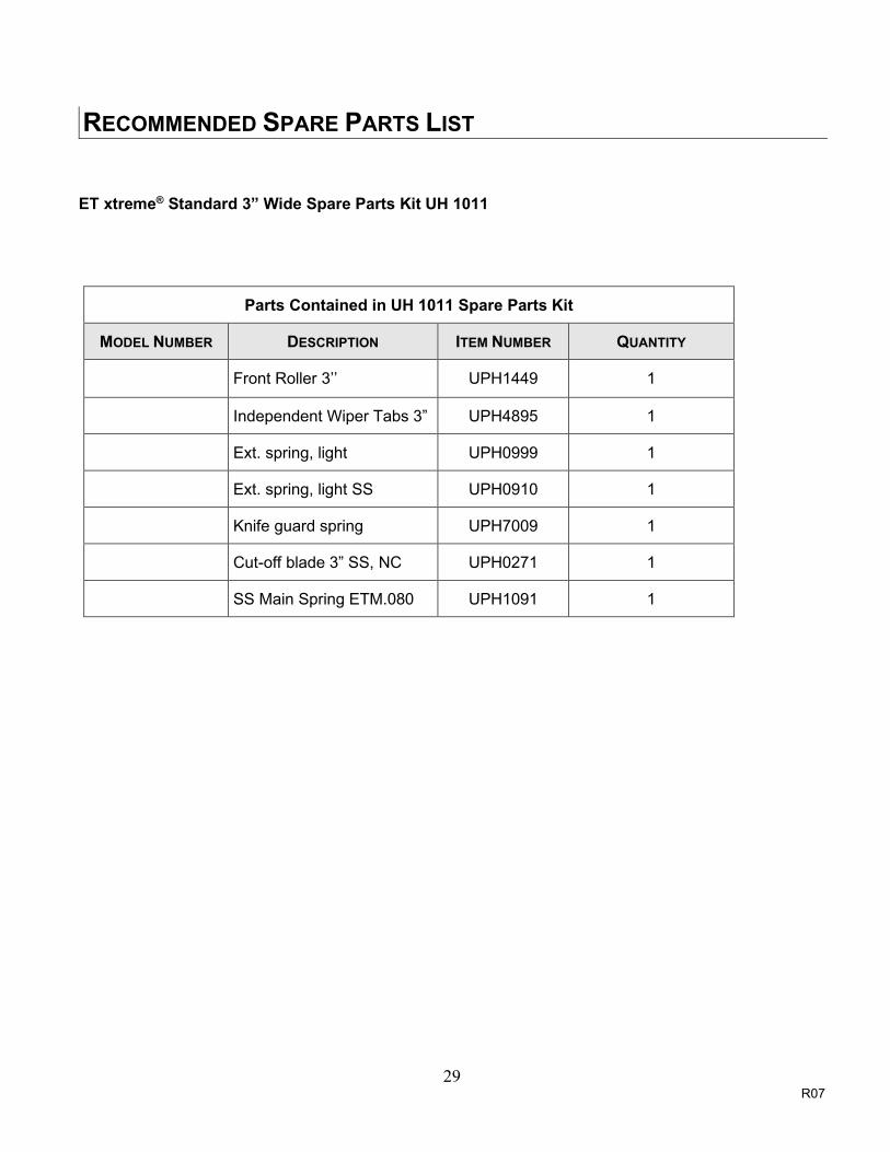
RECOMMENDED SPARE PARTS LIST ET xtreme® Standard 3” Wide Spare Parts Kit UH 1011
Parts Contained in UH 1011 Spare Parts Kit
MODEL NUMBER DESCRIPTION ITEM NUMBER QUANTITY
Front Roller 3’’ UPH1449 1
Independent Wiper Tabs 3” UPH4895 1
Ext. spring, light UPH0999 1
Ext. spring, light SS UPH0910 1
Knife guard spring UPH7009 1
Cut-off blade 3” SS, NC UPH0271 1
SS Main Spring ETM.080 UPH1091 1

30 R07
REAR ROLLER
M5 BHCS
BLADE
FRONT ROLLER
PREVENTIVE MAINTENANCE WARNING! TURN OFF ELECTRICAL POWER SUPPLY AND DISCONNECT THE POWER CORD FROM THE
ELECTRICAL SUPPLY BEFORE BEGINNING TO WORK ON THE TAPE HEADS OR TO LOAD TAPE. IF POWER CORDS ARE NOT DISCONNECTED, SEVERE INJURY TO PERSONNEL COULD RESULT.
The ET xtreme® has been designed and manufactured with the finest components to provide long, trouble free performance. General preventive maintenance will improve performance and prolong the life of the tape head. Please review the illustration and chart below for information regarding tape head maintenance. UUUKnife Blade Replacement The knife blade is made from stainless steel and should provide a minimum of 250,000 cycles before replacement.
The cut-off blade is secured in position using two (2) M5 Button Head Cap Screws. To replace the cut-off blade:
1. Loosen both screws with a 3 mm hexagonal key. Do not remove the screws.
2. Remove the blade by sliding out.
3. Insert the new blade with the inclined face facing toward the rear roller.
4. Ensure the blade goes all the way against the screws and tighten properly.
Figure 10-1

31 R07
PREVENTIVE MAINTENANCE UUULubrication The ET xtreme® components ship from the factory permanently lubricated. No additional lubrication is necessary, however, a small amount of lightweight oil applied to rotating and pivot points will extend the life of the tape head and assure maximum performance. There is a felt pad however on the blade guard that serves as an oiler pad to help keep the blade free of adheisive accumulation. Add a small amount of lightweight oil (mineral oil, food grade 70) or silicon spray so that when a case is processed, the oil from the pad is transferred to the blade as the knife guard is opened and closed (refer to Preventative Maintenance on pg. 40 for further information). UUUOiler Pad Lubrication WARNING! USE CAUTION WHEN OILING THIS PAD AS THE CUTTER BLADE IS VERY SHARP. DO NOT OPERATE
THE TAPE HEAD WITHOUT THE FELT PAD OR BLADEGUARD FOR THAT MATTER.
1. Retract the blade guard.
2. Remove any debris or accumulated adhesive build up.
3. Apply 5 to 10 drops of either mineral oil or silicon lubricant to the pad.
4. Release the blade guard against the blade.
Figure 10-2
PAD

32 R07
PREVENTIVE MAINTENANCE UUUApplication Roller Replacement These blue rollers are wear items and should be inspected regularly and replaced if necessary.
Front & Rear Urethane Roller Replacement Removing The Urethane Roller
1. Using two allen keys, remove the M6 screws. 2. Application of heat may be required to break loose
from the threading agent. When one of the M6 screws comes out, insert a 5 mm allen key into its place, thereby locking down the shaft.
3. Now one can proceed to remove the other screw. 4. Remove the PTFE washer and spring washer. 5. Remove the front roller hub. 6. With a sharp utility knife, cut away the blue
urethane roller from its roller core.
Installing The New Urethane Roller
1. Moisten the roller core’s outside and the urethane
roller’s inside by applying soapy water or foam. 2. Feed the urethane roller onto the end of the roller
core. The closed air pocket will help the urethane tube to hop over the core.
3. Press the urethane roller until it reaches the roller core’s rim/shoulder. (do not exert excessive force so that the rim would crack)
4. Place roller back onto the shaft, rimmed side closer to main frame.
5. To reinstall back into the roller arm, refer to Figure 10-3. for an exploded view. The smaller PTFE washer (UF6402) will go to the clutch bearing side, the bigger PTFE washers (UF6335) and the disc spring (UF4401) go into the recessed side of the roller core.
NOTE: The front roller assembly should have just enough tension, so that it is not free spinning. Apply a drop of purple Loctite on the M6 Screws when reassembling. Ascertain that Loctite does not bleed out (as it could prevent spinning).
M6 –SCREW
Figure 10-4
URETHANE BLUE ROLLER ROLLER
CORE
PTFE WASHER UF6402
SPRING WASHER
Figure 10-3
PTFE WASHER UF6335
SPRING

33 R07
PREVENTIVE MAINTENANCE UUUSpring Replacements There are three springs on the ET xtreme® tape head. These springs are wear items and should be inspected regularly and replaced if necessary. Below are instructions for replacing the two most common springs. Main Spring Replacement
1. Using a spring puller tool, remove one end of the main spring from the spring retainer.
2. Take off the damaged spring.
3. Hook one end of the new spring over the nylon spring retainer sleeve’s groove.
4. Stretch the spring over rear arms spring retainer ring using either a spring puller (10” approx.) or your fingers. Hook the loop securely into the retainer’s groove.
Figure 10-5
Hook Pole
Spring Retainer

34 R07
PREVENTIVE MAINTENANCE
Knife Arm Spring Replacement If the compression spring breaks, the sequence to change it is as follows.
1. Remove the snap ring attached to the knife arm assembly. (Wear safety glasses while working with retaining rings).
Figure 10-6
2. Slide off the repulsive pivot assembly from current position as shown in Figure 10-7.
Figure 10-7
3. Remove the spring barrel from over-lapping
position as shown in Figure 10-8. Remove any broken particle from the spring guide. Install new compression spring into the captive position.
Figure 10-8
Snap Ring

35 R07
PREVENTIVE MAINTENANCE
4. Press the spring barrel against the spring mandrel until it is ready to slide back on the short shaft. See Figure 10-9. Move the whole sub assembly back to its original position.
5. Reinsert retaining ring to the groove. Should the 10 mm retaining ring get damaged replace it with a new one. (Figure 10-10.) Calibrate the spring pressure with the M6 nylon lock nut as described earlier.
Snap Ring
Figure 10-9
Figure 10-10

36 R07
BLADE
M5 BHCS
FRONT ROLLER
PREVENTIVE MAINTENANCE
Knife Guard Spring Replacement
Figure 10-11
Remove the cross shaft NOTE: These screws are secured with loctite and may require applied heat prior to removal.
1. Using two 2mm hexagonal keys as shown, remove one of the flathead screws by applying force on both hexagonal key in an attempt to break free one from locking agent.
2. Once one of the screws is free, only continue to remove that screw.
3. Leave the remaining flathead screw that did not yield, attached to the cross shaft.
Figure 10-12
2mm Hex. Key
As a precaution, remove the cutter blade to avoid injury.

37 R07
PREVENTIVE MAINTENANCE
Carefully slide out the shaft from the end of the shaft that contains the remaining flathead screw.
Remove the broken spring.
Figure 10-13
Figure 10-14

38 R07
Figure 10-16
PREVENTIVE MAINTENANCE
To properly position the new knife spring
1. Position the new knife spring as shown in Figure 10-15.
2. Note which leg of the spring should lie behind the cutter blade mounting plate.
3. Note that the looped leg shall wrap around the blade guard.
Insert the cross shaft through the knife arm, knife guard and knife guard spring as shown in Figure 10-16.
Behind The Cutter Blade Mounting
In Front Of Knife Guard
Figure 10-15

39 R07
PREVENTIVE MAINTENANCE
To Complete The Installation:
1. Apply some (purple) Loctite 222 to the threads of the M3 screw and fasten to the end of the cross shaft. Tighten using two 2mm hexagonal keys as shown in Figure 10-17.
2. The shaft should not vacillate in the mounting holes.
3. Rotate the knife guard to make sure there is no binding.
4. Re-install the cutter blade as shown in Figure 10-11.
5. Inspect the oiler pad to make sure it is securely fastened. Clean the pad and apply some lightweight oil.
6. Check that the magnet catch is spinning free, if not spray the pin with silicon based lubricant.
Figure 10-17

40 R07
4
2
3
1
1
PREVENTIVE MAINTENANCE UUUDual Wipe Down Tabs Replacement The dual independent wiper tabs assist in wiping down the top center seam of the case. While the blue tucking rollers perform much of the wipe down, the wipe down tabs enhance the wipe down as it presses the adhesive into the corrugated fiber. Over time, these tabs can become distorted or worn and they should be replaced.
Dual Wiper Tabs’ Replacement 1. Remove the two M4 hex nuts
(Item 1) from the rear arm with a 7mm wrench.
2. Unscrew the two M4 bottom head countersunk screws (item 2).
3. Remove the rectangular washer (Item 3) and the dual Wiper Tabs (Item 4).
4. Install new Wiper Tabs with two M4 button head screws as shown in Figure 10-18. Check for the correct orientation. Peel off removable label.
Figure 10-18

41 R07
SCHEDULE OF PREVENTIVE MAINTENANCE
Item Action Required Material Weekly Monthly QuarterlyBlade Guard Oiler Pad Lubricate Lightweight oil XHardware Re-tighten any loose hardware X
Replace any missing hardware XCutter Blade Inspect for wear X
Clean Solvent Cleaner XMandrel Assembly Disassemble & Observe X
Mandrel Friction Washer Clean Solvent Cleaner XMandrel Metal Washer None None X
Mandrel Shaft Remove any dust and adhesive build up Solvent Cleaner XMandrel Bearing Check for wear None X
Peel Roller XDelrin Roller Check for free spinning. Disassemble and
remove any adhesive build up. Solvent CleanerX
Pivot Shaft Check for any restriction Solvent Cleaner XPeel Roller Spring Check for total extension when force. X
Plastic Guide Rollers Check for free spinning. Disassemble and remove any adhesive build up. Solvent Cleaner
X
Knurled PTFE Coated Direction Clutch Roller
Back off tension. Check for free spinning. Disassemble and remove any adhesive build up. Oil needle rollers. Solvent Cleaner
X
Knurled PTFE Guide Rollers Rotation should be slightly restricted by spring. Disassemble and remove any adhesive build up if excessive restriction is detected. Check one way bearing grease bearing.
Oiled string and Damp Cloth
X
Front Blue Wipe Down Roller Rotation should be slightly restricted by spring washer. Disassemble and remove any adhesive build up if excessive restriction is detected. Solvent Cleaner
X
Rear Blue Wipe Down Roller Check for free spinning. Disassemble and remove any adhesive build up. Check swivel bushing. Solvent Cleaner
X
Main Spring Remove and inspect for any wear or weakness. Replace as necessary.
X
Knife Spring Remove and inspect for any wear or weakness. Replace as necessary.
X
Tape Shoe Guide Compression Spring
Inspect for finger popping up. Replace as necessary.
X
Wipe Down Tab Inspect for any wear or weakness. Replace as necessary.
X
Main Applying And Wipe Down Assembly
Remove Main Spring and check for any restrictions when assembly is in motion
Worn bearings, bent shafts, bent roller arms
X
Knife Arm Assembly Remove Knife Spring and check for any restrictions when assembly is in motion
Worn bearings, bent shafts.
X
Frequency
Refer To Assembly Drawings For Part Numbers Of Replacement Parts If Required

42 R07
APPENDIX A – ILLUSTRATIONS & PARTS LISTS Tape Head Sub Assemblies ........................................................................................... 44 Main Frame Assembly .................................................................................................... 46 Cover Frame Assembly .................................................................................................. 48 Front Arm Assembly....................................................................................................... 50 Guide Roller ...................................................................................................................... 52 Tape Shoe Assembly ........................................................................................................ 54 Front Roller ....................................................................................................................... 56 Rear Arm Assembly ........................................................................................................ 58 Link Assembly ................................................................................................................ 60 Knife Arm Assembly ....................................................................................................... 62 Clutch Assembly ............................................................................................................. 64 Clutch Roller ..................................................................................................................... 66 Mandrel Assembly .......................................................................................................... 68
Mandrel Arm Sub Assembly.............................................................................................. 70
Mandrel Hub ..................................................................................................................... 72
Repulsive Pivot Assembly ............................................................................................. 74
Peel-Off Assembly .......................................................................................................... 76
No Tape Sensor (Option) .................................................................................................. 78
Low Tape Sensor (Option) ................................................................................................ 80

43 R07
THIS PAGE INTENTIONALLY LEFT BLANK

4 6
108
1
9
3
5
7
2
111213
44

ITEM PART # DESCRIPTION UH230T 2"/QTY.
UH430T 3"/QTY.
1 USH1178 MAIN FRAME ASS'Y 2" 1 -1 USH1179 MAIN FRAME ASS'Y 3" - 12 USH1118 COVER FRAME ASSEMBLY 1 -2 USH1114 COVER FRAME ASSEMBLY - 13 USH1120 FRONT ARM ASSEMBLY 1 -3 USH1119 FRONT ARM ASSEMBLY - 14 USH1121 REAR ARM ASSEMBLY 1 -4 USH1103 REAR ARM ASSEMBLY - 15 USH4133 LINK ASS'Y 1 16 USH1122 KNIFE ARM ASS'Y 2" 1 -6 USH1123 KNIFE ARM ASS'Y 3" - 17 USH1124 CLUTCH ASSEMBLY 1 -7 USH1125 CLUTCH ASSEMBLY - 18 USH1126 MANDREL ASSEMBLY 1 -8 USH1127 MANDREL ASSEMBLY - 19 USH1129 REPULSIVE PIVOT ASS'Y SS 1 1
10 USH1111 PEEL-OFF ASSEMBLY 2" 1 -10 USH1112 PEEL-OFF ASSEMBLY 3" - 111 UPH1424 SAFETY COVER 2" 1 -11 UPH1314 SAFETY COVER 3" - 112 UPH0910 EXTENSION SPRING 1 113 UPH1091 MAIN SPRING 1 1
45

1
17
2
3
8
1214
16
9
13
10
11
18
16
15
15
2019
45
6 7
6 7
A2324R05

ITEM PART # DESCRIPTION USH1178 2"/QTY.
USH1179 3/"QTY.
1 UPH1313 MAIN FRAME 1 12 UPH4040 SPACER BAR 2 -2 UPH1367 SPACER BAR - 23 UPH1387 SHAFT 10mm Dia. 1 -3 UPH1363 SHAFT 10mm Dia. - 14 UPH1416 SHAFT 12mm Dia. W/ SNAP RING - 15 UPH1423 SHAFT 12mm Dia. W/ SNAP RING 1 -6 UPH1422 SHAFT 12mm Dia. 2 -7 UPH1364 SHAFT 12mm Dia. - 28 UF3282 SS FHCS M5-0.8 x 12 mm 2 29 UF3277 SS FHCS M5-0.8 x 16 mm 7 710 UPH3856 SS FLAT WASHER 1 111 UPH4886 SPACER WASHER 1 112 UPH133 URETHANE STOP 2 213 UPH1515 URETHANE STOP 1 114 UPH1017 SS STOP RETAINER 3 315 UF6336 F.W. PTFE, 13 x 19 x 1 mm 2 216 UF6335 F.W. PTFE, 12.5 x 20 x 0.55 mm 2 217 UF7012 SS FHCS M5-0.8 x 8 mm 2 218 UF7017 SS RET'G RING EXTERNAL 12mm 1 119 UF9170 SS FHCS M3-0.5 x 12 2 220 UAH0257 MAGNET ASS'Y 2" 1 -20 UAH0258 MAGNET ASS'Y 3" - 1

6
11
8
14
2
12
9
7
10
5
3
3
A2338R02
13
48

ITEM PART # DESCRIPTION USH1118 2"/QTY.
USH1114 3"/QTY.
1 UPH3909 RETAINER, MAIN SPRING - 12 UPH0863 MAIN SPRING RETAINER SLEEVE 1 13 UF3277 SS FHCS M5 - 0.8 x 16 mm 9 94 UF7012 SS FHCS M5-0.8 x 8 mm 2 25 UPH4041 SPACER BAR 1 -5 UPH1368 SPACER BAR - 16 UPH1365 COVER FRAME 1 17 UPH1417 URETHANE STOP 1 18 UPH133 URETHANE STOP 1 19 UPH1017 SS STOP RETAINER 2 210 UF3282 SS FHCS M5-0.8 x 12 mm 1 111 UPH4886 SPACER WASHER 1 112 UF3556 RETAINING RING 9 mm SS 1 113 UF9170 SS FHCS M3-0.5 x 12 2 214 UPH3908 RETAINER, MAIN SPRING 1 -
49

6
7
15
11
10
14
4
2
9
3
5
13
12
8
1
16
A2348R03
50

ITEM PART # DESCRIPTION USH1120 2"/QTY.
USH1119 3"/QTY.
1 UAH0180 FRONT ARM 2" 1 -1 UAH0181 FRONT ARM 3" - 12 UPH1436 LIMIT BLOCK 1 -2 UPH1437 LIMIT BLOCK - 13 UPH1473 SLEEVE TUBING 1 14 UPH4890 COMPRESSION SPRING 1 15 UF6425 SS FHCS M3-0.5 x 30mm 1 16 UAH0208 TAPE SHOE ASS'Y 2" 1 -6 UAH0209 TAPE SHOE ASS'Y 3" - 17 UPH1442 SHAFT, 10mm Dia. 1 -7 UPH1441 SHAFT, 10mm Dia. - 18 UF3277 SS FHCS M5 - 0.8 x 16 mm 2 29 UAH0222 FRONT ROLLER ASS'Y 48 1 -9 UAH0223 FRONT ROLLER ASS'Y 72 - 110 UF3261 SS FHCS M6 -1 x 16 mm 2 211 UPH1446 SHAFT 8 mm Dia. - 111 UPH1447 SHAFT 8 mm Dia. 1 -12 UF3761 SS FHCS M4-0.7 x 12mm 2 213 UF9170 SS FHCS M3-0.5 x 12 2 214 UF4511 SS RET. RING EXT. 8mm 1 115 UF5608 SPECIAL WASHER 2 216 UAH0182 GUIDE ROLLER ASS'Y 2" 1 -16 UAH0183 GUIDE ROLLER ASS'Y 3" - 1
51

2
1 3
1 3
A2357R02
UAH0182 / UAH0183

ITEM PART # DESCRIPTION UAH0182 2"/QTY.
UAH0183 3"/QTY.
1 UPH4925 GUIDE ROLLER - 2
2 UPH4926 COMPRESSION SPRING 1 1
3 UPH4924 GUIDE ROLLER 2 -

2
4
1
5
3
A2401R01
54

ITEM PART # DESCRIPTION UAH0208 2" / QTY.
UAH0209 3" / QTY.
1 UPH1434 TAPE SHOE 2" 1 -2 UPH1435 TAPE SHOE 3" - 12 UPH1438 STIFFENER BLOCK 1 13 UF6350 SS FHCS M3-0.5 x 8 mm 1 14 UPH7010 SS COMPRESSION SPRING 1 15 UPH1510 FINGER 1 1
55

1
2
3
3
65
4
6
7
A2358R02
UAH0222 / UAH0223
EHivatal
Typewritten Text
EHivatal
Typewritten Text

ITEM PART # DESCRIPTION UAH0222 2"/QTY.
UAH0223 3"/QTY.
1 UPH1439 ROLLER CORE 1 -1 UPH1440 ROLLER CORE - 12 UPH8143 SS COMPRESSION SPRING 1 13 UF6402 F.W. PTFE, 12.5 x 17.5 x 0.5 mm 3 34 UPH1448 FRONT ROLLER 1 -4 UPH1449 FRONT ROLLER - 15 UF4401 DISC SPRING 12.2 id - 21 od 1 16 UF6335 F.W. PTFE, 12.5 x 20 x 0.55 mm 2 27 UPH1444 SHAFT, 12mm DIA. 1 -7 UPH1443 SHAFT, 12mm DIA. - 1

51
6
162
7
9
8
14
34
11
12
13
15
10
USH1103 / USH1121
A2310R02

ITEM PART # DESCRIPTION USH1121 2"/QTY.
USH1103 3"/QTY.
1 UAH0168 REAR ARM WITH BUSHINGS - 11 UAH0175 REAR ARM WITH BUSHINGS 1 -2 UPH1362 SHAFT 12mm Dia. 1 13 UPH0863 MAIN SPRING RETAINER SLEEVE 1 14 UPH9249 RETAINER - 14 UPH9248 RETAINER 1 -5 UF3273 SS FHCS M6-1 x 20 1 16 UF3261 SS FHCS M6 -1 x 16 mm 2 27 UPH4674 PIVOTING BEARING 12mm 1 18 UPH4804 REAR WIPE ROLLER - 18 UPH4803 REAR WIPE ROLLER 1 -9 UPH1294 SHAFT, REAR ARM 2 -9 UPH1295 SHAFT, REAR ARM - 210 UF4511 SS RET. RING EXT. 8mm 1 111 UPH4895 DUAL INDEPENDENT WIPER TABS - 111 UPH4894 DUAL INDEPENDENT WIPER TABS 1 -12 UF7006 SS HEX NUT M4-0.7 2 213 UF4325 SS BHCS M4-0.7 x 12mm 2 214 UF3556 RETAINING RING 9 mm SS 1 115 UPH4897 RECTANGULAR WASHER - 115 UPH4896 RECTANGULAR WASHER 1 -16 UF3791 SS SSS M6-1.0 x 30 1 1

2
4
1
3
5
65
A2303R00
60
EHivatal
Typewritten Text

ITEM PART # DESCRIPTION QTY.
1 UPH4802 LINK ROD 12 UPH4803 ROD END BEARING, 8mm 23 UPH4801 ROD EYE SUPPORT 14 UF3735 SS HNR M8-1.25 25 UF5608 SPECIAL WASHER 26 UF6337 F.W. PTFE, 12.5 x 20 x 0.29 mm 1
61
EHivatal
Typewritten Text

2
3
6
5
1
8
4
12
9
79
10
11
A2352R04
62

ITEM PART # DESCRIPTION USH1122 2" / QTY.
USH1123 3" / QTY.
1 UAH0176 KNIFE ARM WITH BUSHINGS 1 -1 UAH0177 KNIFE ARM WITH BUSHINGS - 12 UAH0206 KNIFE GUARD 2" 1 -2 UAH0207 KNIFE GUARD 3" - 13 UPH9175 SHAFT, BLADE GUARD 1 -3 UPH9178 SHAFT, BLADE GUARD - 14 UPH4930 KNIFE AEM EXTENSION LEFT 1 15 UPH4931 KNIFE ARM EXTENSION RIGHT 1 16 UPH0193 SS CUT-OFF BLADE 48 1 -6 UPH0271 SS CUT-OFF BLADE 75 - 17 UF3276 SS BHCS M5-0.8 x 6 2 28 UF3557 SS RETAINING RING FOR 10 mm SHAFT 1 19 UF6350 SS FHCS M3-0.5 x 8 mm 2 2
10 UF6337 F.W. PTFE, 12.5 x 20 x 0.29 mm 2 211 UPH7009 TORSION SPRING 1 112 UF7008 SS BHCS M4-0.7 x 6 6 6
63

5
15
7
6
12
214
4
3
1310
89
1
1116
A2349R03
64

ITEM PART # DESCRIPTION USH1124 2" / QTY.
USH1125 3" / QTY.
1 UAH0212 CLUTCH ROLLER 1 -1 UAH0213 CLUTCH ROLLER - 12 UPH1391 CLUTCH BRACKET 1 13 UPH1452 GUIDE ROLLER - 13 UPH1453 GUIDE ROLLER 1 -4 UPH1454 SHAFT, 10mm - 14 UPH1455 SHAFT, 10mm 1 -5 UPH7077 CLUTCH SHAFT 1 -5 UPH7078 CLUTCH SHAFT - 16 UF3261 SS FHCS M6 -1 x 16 mm 1 17 UF3275 SS FHCS M6 - 1 x 25mm 1 18 UF3404 M6-1.0 LOCK U NUT 1 19 UF3401 NYLON WASHER 15.3 x 6.5 x 0.55 2 210 UF3557 SS RETAINING RING FOR 10 mm SHAFT 1 111 UPH8230 DISC SPRING 1 112 UF5399 FHCS M5-0.8 x 25 1 113 UF6388 NYLON F.W. 10.5 x 16 x 0.85 1 114 UF6389 NYLON WASHER METRIC 1 115 UF6402 F.W. PTFE, 12.5 x 17.5 x 0.5 mm 3 316 UF6353 SS FHCS M6-1 x 12 mm 1 1
65

3
1
2
2
1
3
A2398R01
Standard Tape Head
Standard Tape Head
Mirror Tape Head
66

ITEM PART # DESCRIPTION UAH0212 2" /QTY.
UAH0213 3"/QTY.
UAH0226 2"mir./QTY.
UAH0227 3"mir./QTY.
1 UPH8139 CLUTCH ROLLER 1 - 1 -1 UPH8140 CLUTCH ROLLER - 1 - 12 UPH1034 BEARING 12 x 14 x 12 LG SS 1 1 1 13 UPH4857 ONE WAY BEARING, STAINLESS 1 1 1 1
67

5
2
10
4
11
3
8
67
1
9
12
A2354R03
68

ITEM PART # DESCRIPTION USH1126 2"/QTY.
USH1127 3"/QTY.
USH1192 2" Mir./QTY.
USH1193 3" Mir./QTY.
1 UAH0224 MANDREL ARM SUB ASS'Y 1 1 - -1 UAH0225 MANDREL ARM SUB ASS'Y MIRROR - - 1 12 UAH0178 MANDREL ASS'Y 2" 1 - 1 -2 UAH0179 MANDREL ASS'Y 3" - 1 - 13 UPH7004 SS HEX SOCKET PLUG 1 1 1 14 UPH7687 SHAFT, MANDREL 1 - 1 -4 UPH7688 SHAFT, MANDREL - 1 - 15 UPH1006 SS MANDREL FRICTION WASHER 1 1 1 16 UPH7689 NYLON SPACER 1 1 1 17 UPH4800 ADJUSTMENT SLEEVE 1 1 1 18 UF5904 SS FHCS M5-0.8 x 20mm 1 1 1 19 UF3282 SS FHCS M5-0.8 x 12 mm 2 2 2 210 UF4512 SS M8-1.0 NYLON LOCK NUT 1 1 1 111 UF6335 F.W. PTFE, 12.5 x 20 x 0.55 mm 1 1 1 112 UF7028 NYLON WASHER 1-1/2" x 1/2" x 1/16" 1 1 1 1
69

1
3
2
A2355R01
70

ITEM PART # DESCRIPTION UAH0224 QTY.
UAH0225 Mir./QTY.
1 UPH1459 MANDREL HUB 1 1
2 UPH4808 MANDREL ARM 1 -
2 UPH8150 MANDREL ARM MIRROR - 1
3 UF5904 SS FHCS M5-0.8 x 20mm 3 3
71

9
2
1
8
345
67
A2353R03
UAH0178 / UAH0179
EHivatal
Typewritten Text

ITEM PART # DESCRIPTION UAH0178 2"/QTY.
UAH0179 3"/QTY.
1 UPH1385 MANDREL 1 -
1 UPH1386 MANDREL - 1
2 UPH3767 BEARING 45 x 20 1 1
3 UPH0907 BEARING 12 x 14 x 12 LG. 1 1
4 UPH1384 SPRAG, HOOKED - 1
5 UPH1383 SPRAG, HOOKED 1 -
6 UPH1393 SPRAG - 2
7 UPH1392 SPRAG 2 -
8 UPH1468 COMPRESSION SPRING 6 9
9 UF3820 SS M3 x 15 SELF TAPPING FH 3 3

6
1
2
5
3
4
A2240R01
74

ITEM PART # DESCRIPTION USH1129/QTY.1 UAH0150 SPRING MANDREL V2 -1 UAH0151 SPRING MANDREL V2 SS 12 UPH7678 SPRING GUIDE V2 13 UPH8111 SPRING BARREL V2 -3 UPH8123 SPRING BARREL V2 14 UPH4665 COMP. SPRING 13.7 O.D. 1.7 W.D. 50.8 LONG -4 UPH7427 COMP. SPRING 13.7 O.D. 1.7 W.D. 50.8 L. SS 15 UF6391 F.W. 6 x 16 x 1 mm -5 UF6390 SS F.W. 6 x 16 x 1 16 UF3391 SS NYLON LOCK NUT M6-1.0 1
75

19
4
9
16
6
7
5
8
1
11
3
10
14
12
1513
18
17
2
20
A2335R01
76

ITEM PART # DESCRIPTION USH1111 2"/QTY.
USH1112 3"/QTY.
USH1194 2" Mir./QTY.
USH1195 3" Mir./QTY.
1 UPH1348 PEEL OFF ARM 1 1 1 1
2 UPH1349 PEEL-OFF SLIDING ROD 2 2 2 2
3 UPH1350 PEEL-OFF BLOCK 1 1 1 1
4 UPH1347 PEEL-OFF BASE 1 - 1 -
4 UPH1347 PEEL-OFF BASE - 1 - 1
5 UF6340 SS FW M5 2 2 2 2
6 UF7011 SS BHCS M5-0.8 X 12mm 2 2 2 2
7 UF3169 SS M5-0.8 x 16 SHCS 1 1 1 1
8 UF7021 SS LW M5 1 1 1 1
9 UF3277 SS FHCS M5 - 0.8 x 16 mm 1 1 1 1
10 UF3283 SS BHCS M5-0.8 X 10mm 2 2 2 2
11 UF3781 SS FHCS M6 - 1 x 30mm 1 1 1 1
12 UPH1354 PEEL ROLLER 1 - 1 -
12 UPH1355 PEEL ROLLER - 1 - 1
13 UPH1351 PEEL-OFF ROLLER SHAFT 1 - 1 -
13 UPH1353 PEEL-OFF ROLLER SHAFT - 1 - 1
14 UF7018 SS RETAINING RING 16 mm SHAFT 1 1 1 1
15 UPH1379 SPACER RING 1 1 1 1
16 UPH1361 SS TORSION SPRING LEFT SQ 1 1 - -
16 UPH1511 SS TORSION SPRING RIGHT SQ - - 1 1
17 UPH1358 COMPRESSION SPRING 2 2 2 2
18 UF9173 C-RING 0.3125 4 4 4 4
19 UPH1352 FRICTION WASHER - 1 - 1
20 UF6403 NYLON F.W. 10.5 x 16 x 0.25 1 1 1 177

1 2No Tape options are available
78

ITEM PART # DESCRIPTION QTY.1 UPM7328 PHOTOELECTRIC SENSOR PNP 12 UPM7329 PHOTOELECTRIC SENSOR NPN 1
79

1
2 3
Low Tape options are available
80

ITEM PART # DESCRIPTION QTY.1 UPH8169 PHOTOELECTRIC SENSOR PNP 12 UPH8144 PHOTOELECTRIC SENSOR NPN 13 UF4518 SS BHCS M3 - 0.5 X 6 2
81


