C1/C2 ACCESS SYSTEM - synthes.vo.llnwd.netsynthes.vo.llnwd.net/o16/LLNWMB8/INT Mobile/Synthes...
20
SURGICAL TECHNIQUE Percutaneous transarticular screw fixation. C1/C2 ACCESS SYSTEM Instruments and implants approved by the AO Foundation. This publication is not intended for distribution in the USA.
Transcript of C1/C2 ACCESS SYSTEM - synthes.vo.llnwd.netsynthes.vo.llnwd.net/o16/LLNWMB8/INT Mobile/Synthes...

SURGICAL TECHNIQUE
Percutaneous transarticular screw fixation.
C1/C2 ACCESS SYSTEM
Instruments and implants approved by the AO Foundation.This publication is not intended for distribution in the USA.

Image intensifier control
This description alone does not provide sufficient background for direct use of DePuy Synthes products. Instruction by a surgeon experienced in handling these products is highly recommended.
Processing, Reprocessing, Care and MaintenanceFor general guidelines, function control and dismantling of multi-part instruments, as well as processing guidelines for implants, please contact your local sales representative or refer to:http://emea.depuysynthes.com/hcp/reprocessing-care-maintenanceFor general information about reprocessing, care and maintenance of Synthes reusable devices, instrument trays and cases, as well as processing of Synthes non-sterile implants, please consult the Important Information leaflet (SE_023827) or refer to: http://emea.depuysynthes.com/hcp/reprocessing-care-maintenance

C1/C2 Access System Surgical Technique DePuy Synthes 1
TABLE OF CONTENTS
GENERAL INTRODUCTION General introduction 2
Indications/Contraindications 3
SURGICAL TECHNIQUE Image intensifier-assisted technique 4
PRODUCT INFORMATION Implants 13
Instruments 14
BIBLIOGRAPHY Bibliography 17
1
2
3
2 DePuy Synthes C1/C2 Access System Surgical Technique
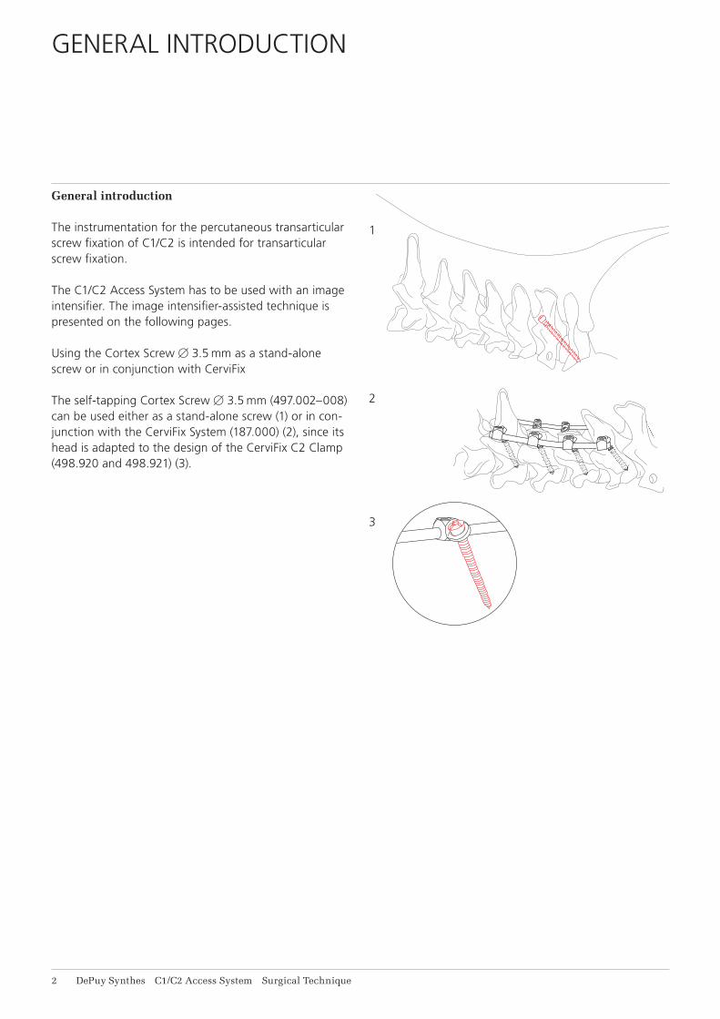
General introduction
The instrumentation for the percutaneous transarticular screw fixation of C1/C2 is intended for transarticular screw fixation.
The C1/C2 Access System has to be used with an image intensifier. The image intensifier-assisted technique is presented on the following pages.
Using the Cortex Screw B 3.5 mm as a stand-alone screw or in conjunction with CerviFix
The self-tapping Cortex Screw B 3.5 mm (497.002–008) can be used either as a stand-alone screw (1) or in con-junction with the CerviFix System (187.000) (2), since its head is adapted to the design of the CerviFix C2 Clamp (498.920 and 498.921) (3).
GENERAL INTRODUCTION

C1/C2 Access System Surgical Technique DePuy Synthes 3
Indications• Traumatic and post-traumatic instability of C1/C2• Pedicle screw fixation according to Judet• Rheumatoid arthritis and degenerative arthrosis• Congenital anomalies• Infections/tumours
ContraindicationsScrew fixation should not be performed if the anatomi-cal situation does not permit stabilisation with screws, as in: • Destruction of the lateral mass of C1 and/or C2• Excessively narrow isthmus (Pars interarticularis) of
C2 (< 6 mm)• Pronounced cervicothoracic kyphosis
It is also contraindicated in cases of inadequate intraop-erative reduction of C1 in relation to C2, with an atlan-todental interval > 8 mm.
INDICATIONS/CONTRAINDICATIONS

4 DePuy Synthes C1/C2 Access System Surgical Technique
IMAGE INTENSIFIER-ASSISTED TECHNIQUE
1Preoperative planning
A meticulous preoperative assessment of the anatomical situation using CT images is essential for determining screw position.
2Reduction and access preparation
Preoperative reduction of C1/C2, using e.g. a Mayfield clamp, is recommended.
The access is designed to expose the lamina and spinous process of C2 and the posterior arch of the atlas.
C1/C2 Access System Surgical Technique DePuy Synthes 5
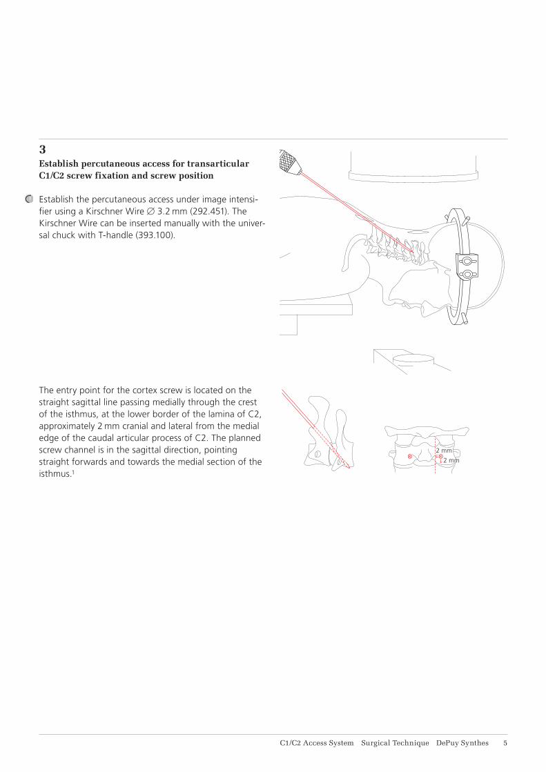
3Establish percutaneous access for transarticular C1/C2 screw fixation and screw position
Establish the percutaneous access under image intensi-fier using a Kirschner WireB3.2 mm (292.451). The Kirschner Wire can be inserted manually with the univer-sal chuck with T-handle (393.100).
The entry point for the cortex screw is located on the straight sagittal line passing medially through the crest of the isthmus, at the lower border of the lamina of C2, approximately 2 mm cranial and lateral from the medial edge of the caudal articular process of C2. The planned screw channel is in the sagittal direction, pointing straight forwards and towards the medial section of the isthmus.1

6 DePuy Synthes C1/C2 Access System Surgical Technique
Image intensifier-assisted technique
4Prepare entry point for drill bit
Using the tip of the Kirschner wire, prepare the entry point on the bone so as to prevent slippage of the subsequently used Drill Bit B 2.5 mm (387.013) on the sloping bone surface.
5Widen soft tissue access and insert guide sleeve 6.0/3.2
To widen the soft tissue access and insert the Protection Sleeve 8.0/6.0 (387.017), advance the Guide Sleeve 6.0/3.2 (387.011) over the Kirschner wire.

1
2
3
C1/C2 Access System Surgical Technique DePuy Synthes 7
6Insert protection sleeve
Slide the protection sleeve 8.0/6.0 over the guide sleeve and, with rotating movements, advance through the soft tissue as far as C2.
Locate the protection sleeve 8.0/6.0 with its sloping sur-face in the planned screw direction against the lamina of C2 (1).
After positioning the protection sleeve, remove the Kirschner wire and guide sleeve.
Note: When advancing the guide sleeve and the pro-tection sleeve, take care to ensure that the Kirschner wire does not become dislocated and pen-etrate the spinal canal.
For better handling, the handle (2) of the protection sleeve can be readjusted by loosening the screw (3).

1
2
3
8 DePuy Synthes C1/C2 Access System Surgical Technique
7Create screw channel
To create the screw channel, use the drill bit B 2.5 mm (387.013S) (1) with Guide Sleeve 6.0/2.5 (387.014) (2) (both marked yellow), since the latter guides the cutting part of the drill (3) and ensures close contact with the bone. This reduces the risk of bending at the transition between bone and guide sleeve (4).
Note: If the drill bit cannot be held in straight align-ment with its axis, significant leverage can be ex-erted on the long bit by the drill unit and the drag of the air-hose. This potentially causes the bit to bend, particularly at the transition between the bone and the protection/guide sleeve.
Image intensifier-assisted technique

4
C1/C2 Access System Surgical Technique DePuy Synthes 9
The drill bit can break if
• it is bent excessively or repeatedly and/or• it is bent and, simultaneously, a high torque is applied
to the bit via the drill unit.
Consequently, the drill bit is to be used only with a drill unit with a continuously variable and manually adjust-able rotational speed. Synthes recommends the Electric Pen Drive 60 000 rpm (05.001.010) or the Air Pen Drive 60 000 rpm (05.001.080). Optional, the Colibri II (532.101) or the Compact Air Drive II (511.701) can be used.
For reasons of safety and accuracy during drilling, and given the risk of fracture through possible repeated bending stresses, the drill bit is designed for single use only.
Once the drill bit is already in the bone, it is no longer possible to change the direction of drilling. An attempt to realign the drill will lead to bending of the free por-tion of the bit and excessive mechanical loading.
The direction of drill can therefore be changed only if the drill bit is repositioned.
2
1
11 DePuy Synthes C1/C2 Access System Surgical Technique
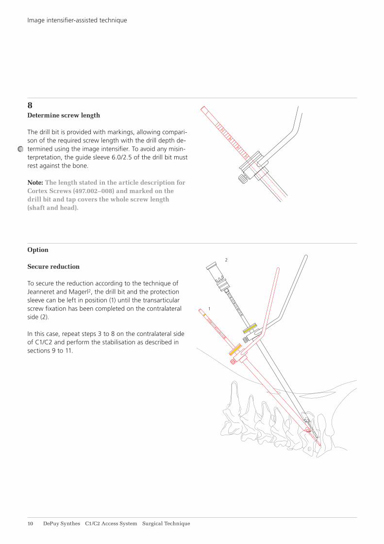
8Determine screw length
The drill bit is provided with markings, allowing compari-son of the required screw length with the drill depth de-termined using the image intensifier. To avoid any misin-terpretation, the guide sleeve 6.0/2.5 of the drill bit must rest against the bone.
Note: The length stated in the article description for Cortex Screws (497.002–008) and marked on the drill bit and tap covers the whole screw length (shaft and head).
Option
Secure reduction
To secure the reduction according to the technique of Jeanneret and Magerl2, the drill bit and the protection sleeve can be left in position (1) until the transarticular screw fixation has been completed on the contralateral side (2).
In this case, repeat steps 3 to 8 on the contralateral side of C1/C2 and perform the stabilisation as described in sections 9 to 11.
Image intensifier-assisted technique

1
2
3
C1/C2 Access System Surgical Technique DePuy Synthes 11
9Tap thread
If the bone is sclerotic, the thread should be tapped beforehand. Use the Tap B 3.5 mm (387.015) (1) with Guide Sleeve 6.0/3.5 (387.016) (2) (both marked blue) and connect to the universal chuck with T-handle (393.100). This sleeve guides the tap in the protection sleeve and provides addi tional stability in the tapped section (3).
Check the position of the tap during tapping under the image intensifier.
Note: Any taps that have become bent should be re-placed since, owing to their length, any additional mechanical loading increases the risk of breakage.
10Pick up cortex screw with self-holding screwdriver
Since the Cortex Screw B 3.5 mm (497.002–008) has a special head, it can be used only in conjunction with the self-holding Screwdriver (387.018).
To pick up the cortex screw, locate the screwdriver on the cross-recessed head of the cortex screw. Turn the connecting screw of the screwdriver to connect the screw firmly to the screwdriver. Ensure that the cross of the screwdriver is fully inserted in the cruciform recess of the screw head.
12 DePuy Synthes C1/C2 Access System Surgical Technique
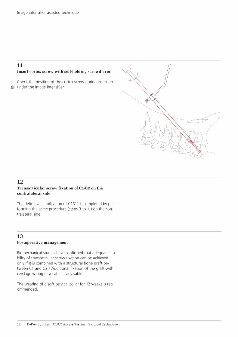
11Insert cortex screw with self-holding screwdriver
Check the position of the cortex screw during insertion under the image intensifier.
12Transarticular screw fixation of C1/C2 on the contralateral side
The definitive stabilisation of C1/C2 is completed by per-forming the same procedure (steps 3 to 11) on the con-tralateral side.
13Postoperative management
Biomechanical studies have confirmed that adequate sta-bility of transarticular screw fixation can be achieved only if it is combined with a structural bone graft be-tween C1 and C2.3 Additional fixation of the graft with cerclage wiring or a cable is advisable.
The wearing of a soft cervical collar for 12 weeks is rec-ommended.
Image intensifier-assisted technique
C1/C2 Access System Surgical Technique DePuy Synthes 13
IMPLANTS
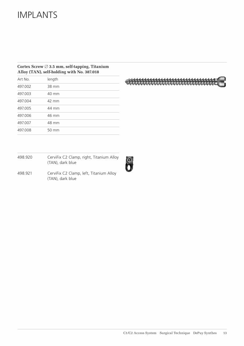
Cortex Screw B 3.5 mm, self-tapping, Titanium Alloy (TAN), self-holding with No. 387.018
Art No. length
497.002 38 mm
497.003 40 mm
497.004 42 mm
497.005 44 mm
497.006 46 mm
497.007 48 mm
497.008 50 mm
498.920 CerviFix C2 Clamp, right, Titanium Alloy (TAN), dark blue
498.921 CerviFix C2 Clamp, left, Titanium Alloy (TAN), dark blue

14 DePuy Synthes C1/C2 Access System Surgical Technique
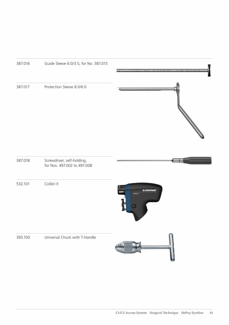
INSTRUMENTS
187.000 CerviFix in Vario Case
292.451 Kirschner Wire B 3.2 mm with trocar tip, length 300 mm, Stainless Steel
387.011 Guide Sleeve 6.0/3.2, for Kirschner Wire No. 292.451
387.013 Drill Bit B 2.5 mm with Stop, length 270/70 mm, 3-flute, for Jacobs Chuck
387.013S Drill Bit B 2.5 mm with Stop, length 270/70 mm, 3-flute, for Jacobs Chuck, sterile
387.014 Guide Sleeve 6.0/2.5, for Drill Bits No. 387.013
387.015 Tap for Cortex Screws B 3.5 mm, with Stop, length 270/70 mm, for Jacobs Chuck
C1/C2 Access System Surgical Technique DePuy Synthes 15
387.016 Guide Sleeve 6.0/3.5, for No. 387.015
387.017 Protection Sleeve 8.0/6.0
387.018 Screwdriver, self-holding, for Nos. 497.002 to 497.008
532.101 Colibri II
393.100 Universal Chuck with T-Handle
16 DePuy Synthes C1/C2 Access System Surgical Technique
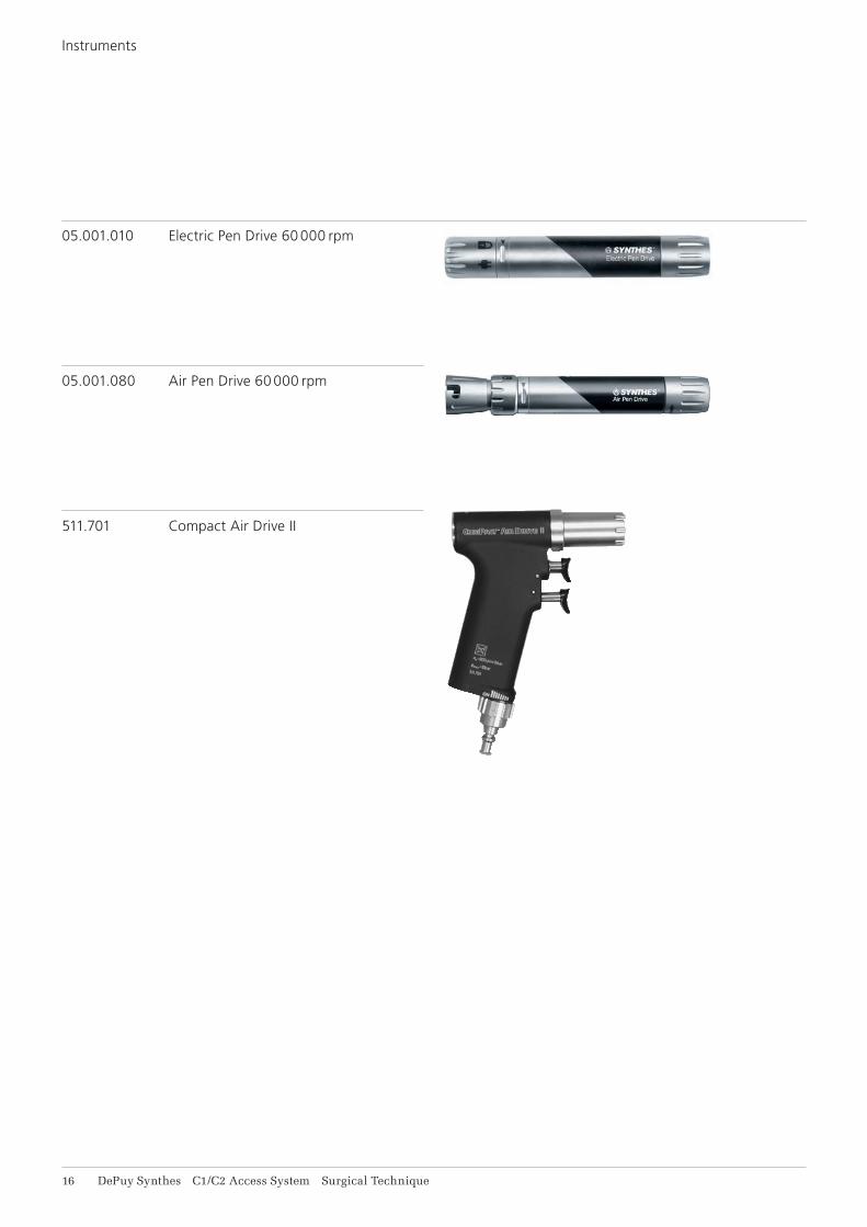
Instruments
05.001.010 Electric Pen Drive 60 000 rpm
05.001.080 Air Pen Drive 60 000 rpm
511.701 Compact Air Drive II

C1/C2 Access System Surgical Technique DePuy Synthes 17
1. Aebi M, Thalgott J S and Webb J (1998) AO ASIF Principles in Spinal Surgery, c. 5.2 Transarticular Screw Fixation, Springer, Berlin
2. Jeanneret B and Magerl F (1992) Primary Posterior Fusion C1/2 in Odontoid Fractures: Indications, Tech-nique, and Results of Trans articular Screw Fixation. J Spinal Disord (United States), Dec, 5 (4): 464–75
3. Henriques T, Cunningham BW, Olerud C et al. (2000) Bio mechanical Comparison of Five Different Atlanto-axial Posterior Fixation Techniques. Spine, 25 (22): 2877–83
BIBLIOGRAPHY

0123
Synthes GmbHEimattstrasse 34436 OberdorfSwitzerlandTel: +41 61 965 61 11Fax: +41 61 965 66 00www.depuysynthes.com ©
DeP
uy S
ynth
es S
pine
, a d
ivis
ion
of S
ynth
es G
mbH
. 201
6.
All
right
s re
serv
ed.
036.
000.
258
DS
EM
/SP
N/0
416/
0475
08
/16
Not all products are currently available in all markets.
This publication is not intended for distribution in the USA.
All surgical techniques are available as PDF files at www.depuysynthes.com/ifu