C192PF8-RPR Power Factor Manager - Satec Global · This manual is intended for the user of the...
75
C192PF8 -RPR Power Factor Manager & Reactive Power Regulator Installation and Operation Manual BG0347 Rev. A1
Transcript of C192PF8-RPR Power Factor Manager - Satec Global · This manual is intended for the user of the...

C192PF8-RPRPower Factor
Manager &Reactive Power Regulator
Installation and Operation
Manual
BG0347 Rev. A1

C192PF8-RPR Power Factor Manager and Reactive Power Regulator
Installation and Operation Manual

i
LIMITED WARRANTY The manufacturer offers the customer an 24-month functional warranty on the instrument for faulty workmanship or parts from date of dispatch from the distributor. In all cases, this warranty is valid for 36 months from the date of production. This warranty is on a return to factory basis.
The manufacturer does not accept liability for any damage caused by instrument malfunction. The manufacturer accepts no responsibility for the suitability of the instrument to the application for which it was purchased.
Failure to install, set up or operate the instrument according to the instructions herein will void the warranty.
Your instrument may be opened only by a duly authorized representative of the manufacturer. The unit should only be opened in a fully anti-static environment. Failure to do so may damage the electronic components and will void the warranty.
NOTE
The greatest care has been taken to manufacture and calibrate your instrument. However, these instructions do not cover all possible contingencies that may arise during installation, operation or maintenance, and all details and variations of this equipment are not covered by these instructions.
For additional information regarding installation, operation or maintenance of this instrument, contact the manufacturer or your local representative or distributor.
IMPORTANT
Please read the instructions this manual before performing installation, and take note of the following precautions:
Ensure that all incoming AC power and other power sources are turned OFF before performing any work on the instrument. Failure to do so may result in serious or even fatal injury and/or equipment damage.
Before connecting the instrument to the power source, check the labels on the side of the instrument to ensure that your instrument is equipped with the appropriate power supply voltage, input voltages, currents and communication protocol for your application.
Under no circumstances should the instrument be connected to a power source if it is damaged.
To prevent potential fire or shock hazard, do not expose the instrument to rain or moisture.
ii
The secondary of an external current transformer must never be allowed to be open circuit when the primary is energized. An open circuit can cause high voltages, possibly resulting in equipment damage, fire and even serious or fatal injury. Ensure that the current transformer wiring is made through shorting switches and is secured using an external strain relief to reduce mechanical strain on the screw terminals, if necessary.
Setup procedures must be performed only by qualified personnel familiar with the instrument and its associated electrical equipment.
DO NOT open the instrument under any circumstances.
Modbus is a trademark of Modicon, Inc.
Read this manual thoroughly before connecting the meter to the current carrying circuits. During operation of the meter, hazardous voltages are present on input terminals. Failure to observe precautions can result in serious or even fatal injury or damage to equipment.
BG0347 Rev. A1
iii
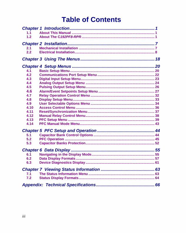
Table of Contents Chapter 1 Introduction....................................................................... 1
1.1 About This Manual .................................................................................... 1 1.2 About The C192PF8-RPR .......................................................................... 1
Chapter 2 Installation......................................................................... 7 2.1 Mechanical Installation ............................................................................. 7 2.2 Electrical Installation................................................................................. 8
Chapter 3 Using The Menus.............................................................. 18
Chapter 4 Setup Menus ..................................................................... 20 4.1 Basic Setup Menu...................................................................................... 20 4.2 Communications Port Setup Menu .......................................................... 22 4.3 Digital Input Setup Menu........................................................................... 23 4.4 Analog Output Setup Menu ...................................................................... 24 4.5 Pulsing Output Setup Menu...................................................................... 26 4.6 Alarm/Event Setpoints Setup Menu ......................................................... 27 4.7 Relay Operation Control Menu ................................................................. 32 4.8 Display Setup Menu................................................................................... 33 4.9 User Selectable Options Menu ................................................................. 34 4.10 Access Control Menu ................................................................................ 36 4.11 Reset/Synchronization Menu.................................................................... 37 4.12 Manual Relay Control Menu...................................................................... 38 4.13 PFC Setup Menu ........................................................................................ 39 4.14 PFC Manual Mode Menu............................................................................ 43
Chapter 5 PFC Setup and Operation ................................................ 44 5.1 Capacitor Bank Control Options .............................................................. 44 5.2 PFC Operation ........................................................................................... 45 5.3 Capacitor Banks Protection...................................................................... 52
Chapter 6 Data Display ...................................................................... 55 6.1 Navigating in the Display Mode................................................................ 55 6.2 Data Display Formats................................................................................ 57 6.3 Device Diagnostics Display ...................................................................... 61
Chapter 7 Viewing Status Information ............................................. 63 7.1 The Status Information Menu ................................................................... 63 7.2 Status Display Formats............................................................................. 64
Appendix: Technical Specifications................................................. 66

Chapter 1 Introduction 1
Chapter 1 Introduction 1.
1.1 About This Manual This manual is intended for the user of the C192PF8-RPR Power Factor Manager and Reactive Power Regulator. The C192PF8-RPR is a multi-function microprocessor-based instrument used for power factor or reactive power correction and for the measurement, monitoring, and management of electrical parameters in low-voltage and mid-voltage power systems.
This chapter gives an overview of this manual and an introduction to the C192PF8-RPR.
Chapter 2, Installation, provides instructions for mechanical and electrical installation.
Chapter 3, Using the Menus, presents the structure of menus for setup and status viewing.
Chapter 4, Setup Menus, provides instructions for performing parameter setup via the front panel.
Chapter 5, PFC Setup and Operation, provides instructions for performing setup for the Power Factor Controller (PFC) and describes front-panel operations in PFC manual mode.
Chapter 6, Data Display, guides you through the display pages.
Chapter 7, Viewing Status Information, tells you how to access additional status information on the instrument. This information may be useful during installation.
Technical Specifications for the C192PF8-RPR are found in the Appendix.
1.2 About The C192PF8-RPR The C192PF8-RPR is a compact three-phase AC Powermeter with a built-in Power Factor Controller (PFC) and Reactive Power Regulator (RPR), designed to meet the requirements of users ranging from electrical panel builders to substation operators. The C192PF8-RPR performs power factor or reactive power correction functions, basic voltage, current, frequency, power, power factor and energy measurements, plus total harmonic (THD, TDD, K-Factor) measurements.
The C192PF8-RPR is suitable for mounting on 136×136 mm square cut-outs.
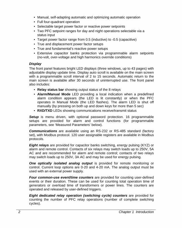
Features Power Factor Controller
• Control of up to 8 capacitor banks
2 Chapter 1 Introduction
• Manual, self-adapting automatic and optimizing automatic operation • Full four-quadrant operation • Selectable target power factor or reactive power setpoints • Two PFC setpoint ranges for day and night operations selectable via a
status input • Target power factor range from 0.5 (inductive) to -0.5 (capacitive) • True and displacement power factor setups • True and fundamental’s reactive power setups • Extensive capacitor banks protection via programmable alarm setpoints
(no-volt, over-voltage and high harmonics override conditions)
Display The front panel features bright LED displays (three windows, up to 43 pages) with adjustable display update time. Display auto scroll is available on the main screen with a programmable scroll interval of 2 to 15 seconds. Automatic return to the main screen is available after 30 seconds of uninterrupted use. The front panel also includes:
• Relay status bar showing output status of the 8 relays • Alarm/Manual Mode LED providing a local indication when a predefined
alarm condition appears (the LED is lit constantly) or when the PFC operates in Manual Mode (the LED flashes). The alarm LED is shut off manually (by pressing on both up and down keys for more than 5 sec)
• RXD/TXD LEDs showing communications receive/transmit status
Setup is menu driven, with optional password protection. 16 programmable setups are provided for alarm and control functions (for programmable parameters, see ‘Measured Parameters’ below).
Communications are available using an RS-232 or RS-485 standard (factory set), with Modbus protocol. 120 user assignable registers are available in Modbus protocols.
Eight relays are provided for capacitor banks switching, energy pulsing (KYZ) or alarm and remote control. Contacts of six relays may switch loads up to 250V, 5A AC and are recommended for alarm and remote control; contacts of two relays may switch loads up to 250V, 3A AC and may be used for energy pulsing.
One optically isolated analog output is provided for remote monitoring or control. Current loop options are 0-20 and 4-20 mA. The analog output must be used with an external power supply.
Four common-use event/time counters are provided for counting user-defined events or their duration. These can be used for counting total operation time of generators or overload time of transformers or power lines. The counters are operated and released by user-defined triggers.
Eight dedicated relay operation (switching cycle) counters are provided for counting the number of PFC relay operations (number of complete switching cycles).

Chapter 1 Introduction 3
One digital input can be used as a status input for monitoring external contacts or as an external synchronization input for power demand interval synchronization. When no external synchronization pulse is provided, the power demand interval can be synchronized through communications.
Three user-selectable options are provided: Power calculation mode Power calculations can be made using directly measured reactive power or through non-active power based on direct apparent power measurements.
Energy rollover value This option specifies the point at which the energy value rolls over to zero.
Phase energy calculations mode This option is used to enable or disable phase energy calculations.
Measured Parameters Note: Real-time values are measured over 1 cycle of fundamental frequency; Average values are sliding average of 8, 16 or 32 real-time measurements.
Output Parameter Dis- play
Com Analog Pulse Alarm
Average Amps, Volts, Frequency $ = setup via PC # = setup via panel
Average RMS voltage per phase L-N √ √ #$ #$ Average RMS voltage per phase L-L √ √ Average RMS current per phase √ √ #$ #$ Average frequency √ √ #$ #$ Average neutral current √ √ #$ #$ Voltage & current unbalance √ √ Amps & Volt Demand Parameters Ampere demand per phase √ #$ Volt demand per phase √ #$ Ampere maximum demand per phase √ √ Voltage maximum demand per phase √ √ Average Power Values Average active power per phase √ √ Average reactive power per phase √ √ Average apparent power per phase √ √ Average total active power √ √ #$ #$ Average total reactive power √ √ #$ #$ Average total apparent power √ √ #$ #$ Average power factor per phase √ √ Average total power factor √ √ #$ #$ Power Demand Parameters Active power accumulated demand √ #$ #$

4 Chapter 1 Introduction
Output Parameter Dis- play
Com Analog Pulse Alarm
Apparent power accumulated demand √ #$ #$ Active power demand √ #$ Active power sliding demand √ #$ Apparent power demand √ #$ Apparent power sliding demand √ #$ Active power predicted demand √ #$ Apparent power predicted demand √ #$ Active power maximum demand √ √ Apparent power maximum demand √ √ Energy Per Phase Active energy import per phase √ √ Reactive energy import per phase √ √ Apparent energy per phase √ √ Total Energy Total active energy import √ √ #$ Total active energy export √ √ #$ Total reactive energy import √ √ #$ Total reactive energy export √ √ #$ Total reactive energy net √ Total reactive energy absolute #$ Total apparent energy √ √ #$ Min/Max Log Min/Max volts √ √ Min/Max amps, neutral current √ √ Min/Max frequency √ √ Min/Max kW, kvar, kVA, PF √ √ Real-time Amps, Volts, Frequency
RT RMS voltage per phase L-N √ #$ #$ RT RMS voltage per phase L-L √ RT RMS current per phase √ #$ #$ RT frequency √ #$ #$ RT neutral current √ Real-time Power Values
RT active power per phase √ RT reactive power per phase √ RT apparent power per phase √ RT total active power √ #$ RT total reactive power √ #$ RT total apparent power √ #$ RT power factor per phase √ RT total power factor √ #$

Chapter 1 Introduction 5
Output Parameter Dis- play
Com Analog Pulse Alarm
Real-time Harmonic Values RT voltage THD per phase √ #$ RT current THD per phase √ #$ RT current TDD per phase √ #$ RT K-Factor per phase √ #$ Average Harmonic Values
Average Voltage THD per phase √ √ Average Current THD per phase √ √ Average Current TDD per phase √ √ Average K-Factor per phase √ √ Fundamental Frequency Values (H01) Voltage & current per phase √ kW, PF per phase √ √ kvar, kVA per phase √ Total kW, PF √ √ Total kvar, kVA √ Phase Rotation √ #$ Counters √ √ Status Input √ √ #$ Relay Status √ √ Remote Relay Control √ Alarm Trigger Status √ #$ Self-Diagnostic Tests √ √
For 4Ln3 and 3Ln3 wiring configurations line to line and line to neutral voltages are displayed and transmitted via communication simultaneously and can be used as triggers for alarm set points; analog output uses line to neutral voltages. For other configurations only line to line voltages are used.

6 Chapter 1 Introduction
Instrument Dimensions
Figure 1-1 C192PF8-RPR Dimensions

Chapter 2 Installation 7
Chapter 2 Installation 2.
2.1 Mechanical Installation Prepare the panel cut-out, 136 x 136 mm, prior to mounting. STEP 1: Place the instrument through the cut-out. STEP 2: Assemble the latches onto the outer wall of the enclosure. STEP 3: Tighten the screws.
Figure 2-1 Mounting the C192PF8-RPR

Chapter 2 Installation
8
2.2 Electrical Installation Before installation ensure that all incoming power sources are shut OFF. Failure to observe this practice can result in serious or even fatal injury and damage to equipment.
Connections to the C192PF8-RPR are made via terminals (voltage and current inputs, power supply, communication, relay and analog output) as shown in Figure 2-2.
2.2.1 Power Supply Connection The power supply can be dedicated-fused, or from a monitored voltage if it is within the instrument’s power supply range. Use an external circuit breaker or switch.
AC power supply: line to terminal 12; neutral to terminal 10. DC power supply: positive to terminal 12; negative to terminal 10.
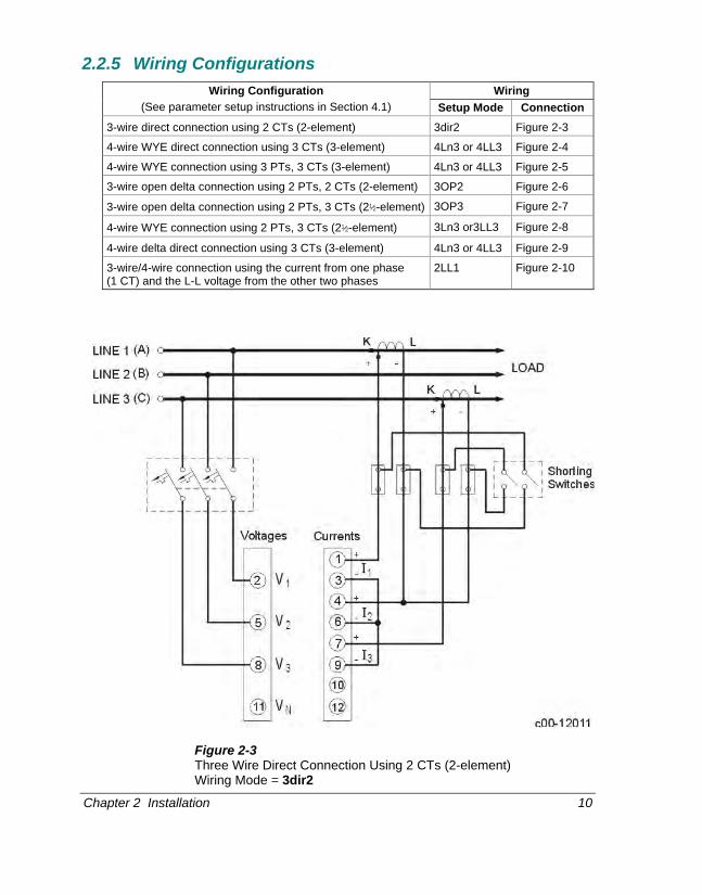
2.2.2 Current Inputs Connect the current inputs to terminals 1, 3, 4, 6, 7, and 9. The instrument is connected to the current transformer as shown in Figures 2-3 through 2-10.
2.2.3 Ground Connect the chassis ground C192PF8-RPR terminal to the switchgear earth ground using dedicated wire of greater than 2.5 mm2/13 AWG.
2.2.4 Voltage Inputs Connect the voltage inputs to terminals 2, 5, 8 and 11. For 690V input, use any of the eight wiring configurations shown in Figures 2-3 through 2-10.
For 120V input, use any of the four wiring configurations shown in Figures 2-5 through 2-8.

Chapter 2 Installation 9
Figure 2-2 C192PF8-RPR Connections - Rear View
Chapter 2 Installation 10
2.2.5 Wiring Configurations Wiring Wiring Configuration
(See parameter setup instructions in Section 4.1) Setup Mode Connection 3-wire direct connection using 2 CTs (2-element) 3dir2 Figure 2-3
4-wire WYE direct connection using 3 CTs (3-element) 4Ln3 or 4LL3 Figure 2-4
4-wire WYE connection using 3 PTs, 3 CTs (3-element) 4Ln3 or 4LL3 Figure 2-5
3-wire open delta connection using 2 PTs, 2 CTs (2-element) 3OP2 Figure 2-6
3-wire open delta connection using 2 PTs, 3 CTs (2½-element) 3OP3 Figure 2-7
4-wire WYE connection using 2 PTs, 3 CTs (2½-element) 3Ln3 or3LL3 Figure 2-8
4-wire delta direct connection using 3 CTs (3-element) 4Ln3 or 4LL3 Figure 2-9
3-wire/4-wire connection using the current from one phase (1 CT) and the L-L voltage from the other two phases
2LL1 Figure 2-10
Figure 2-3 Three Wire Direct Connection Using 2 CTs (2-element) Wiring Mode = 3dir2

Chapter 2 Installation 11
Figure 2-4 Four Wire WYE Direct Connection Using 3 CTs (3-element) Wiring Mode = 4LL3 or 4Ln3
Figure 2-5 Four Wire WYE Connection Using 3 PTs, 3 CTs (3-element) Wiring Mode = 4LL3 or 4Ln3

Chapter 2 Installation
12
Figure 2-6 Three Wire Open Delta Connection Using 2 PTs, 2 CTs (2-element) Wiring Mode = 3OP2
Figure 2-7 Three Wire Open Delta Connection Using 2 PTs, 3 CTs (2½-element) Wiring Mode = 3OP3
Chapter 2 Installation 13
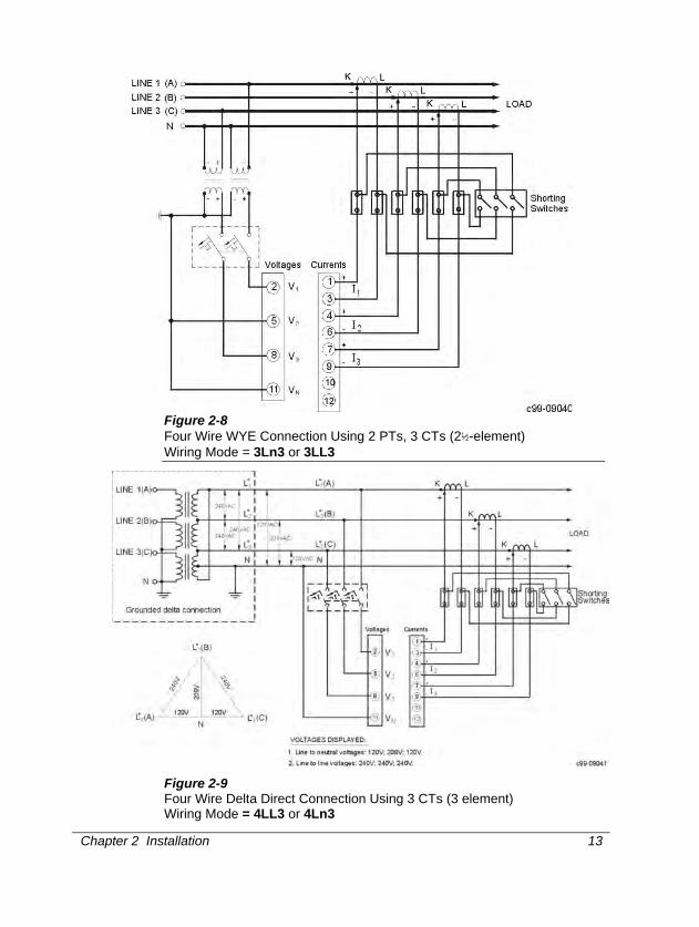
Figure 2-8 Four Wire WYE Connection Using 2 PTs, 3 CTs (2½-element) Wiring Mode = 3Ln3 or 3LL3
Figure 2-9 Four Wire Delta Direct Connection Using 3 CTs (3 element) Wiring Mode = 4LL3 or 4Ln3

Chapter 2 Installation
14
Figure 2-10 Three/Four Wire Direct Connection Using 1 CT Wiring Mode = 2LL1
2.2.6 Relay Eight relays are provided for capacitor bank control (or energy pulsing/alarms).
Figure 2-11 Relay Connection

Chapter 2 Installation 15
2.2.7 Status Input One status input is provided for status monitoring or external synchronization input for power demand period.
Figure 2-12 Status Input Connection
2.2.8 Analog Output The C192PF8-RPR provides one optically isolated analog output with current output options of 0-20 mA and 4-20 mA (current loop load of up to 500 Ohm). The analog output must be used with a 24 V DC external power supply.
Figure 2-13 Analog Output Connection

Chapter 2 Installation
16
2.2.9 Communications The C192PF8-RPR is provided with an RS-232 or RS-485 communication port. Figures 2-14 through 2-18 illustrate the connections.
DSR/CTS
RS-232
POWERMETERRxD
14
SG
TxD15
25-PIN DB25 MALE CONNECTOR
MODEMTxD
GND
2
7
C99-11012
3RxD
Figure 2-14 RS-232 Connection for 25-pin Modem Connector
9-PIN DB9 MALE CONNECTOR
POWERMETER
14
15
13
RS-232
RxD
TxD
SG
TxD3
GND5
c99-11013
MODEMRxD
2
Figure 2-15 RS-232 Connection for 9-pin Modem Connector
RS-232
POWERMETERRxD
14
SG
TxD15
13
25-PIN DB25 FEMALE CONNECTOR
IBM PC/COMPATIBLE
RTS
CTS5
4
TxD
DTR
DSR
RxD
GND
6
20
2
7
3
c99-11014
Figure 2-16 RS-232 Simple 3-Wire Computer Connection, 25-pin
Chapter 2 Installation 17
9-PIN DB9 FEMALE CONNECTOR
POWERMETER
14
15
13
RS-232
RTS
CTS8
7
RxD
TxD
SG
TxD
DTR
DSR6
4
3
RxD
GND5
2
c99-11015
IBM PC/COMPATIBLE
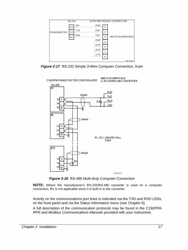
Figure 2-17 RS-232 Simple 3-Wire Computer Connection, 9-pin
Figure 2-18 RS-485 Multi-drop Computer Connection
NOTE: Where the manufacturer's RS-232/RS-485 converter is used on a computer connection, R1 is not applicable since it is built in to the converter.
Activity on the communications port lines is indicated via the TXD and RXD LEDs, on the front panel and via the Status Information menu (see Chapter 6). A full description of the communication protocols may be found in the C192PF8-RPR and Modbus Communications Manuals provided with your instrument.

Chapter 3 Using the Menus
18
Chapter 3 Using The Menus 3. Press and release to enter the setup mode. The primary menus will appear:
Press again to activate the window of the desired primary menu. Press .
Select CHG to initialize or modify the instrument setup, or to clear the accumulated values stored in the instrument. Entry to this menu can be protected by a password. Select StA to view extended status information which may be useful during installation and in certain applications. Select OPS for viewing (not editing) the instrument setup options.
After selecting either OPS or CHG, the list of setup menus is displayed in the upper window. Figure 3-1 presents a complete menu list. Depending on the model of your instrument, some menus may not appear.
Password The Setup Change Menu can be secured by a user-defined password comprised of 4 digits. The instrument is shipped with password protection disabled. To enable password protection, go to the Access Control Menu (see Section 4.10).
The Password Menu appears if password protection is enabled.
To enter a password: Set the first digit using the up and down arrow keys. Press to advance to the next digit. Set the other password digits in the same manner. Press to continue setup. If your password is incorrect, you will return to the Primary Selection Menu.
PASS 0000
SELECT
ENTER
SELECT
SELECT
ENTER
SELECT StA ENTER
SELECT CHG ENTER
SELECT OPS ENTER
StA
CHG
OPS
- Status Information Menu (see Chapter 6)
- Setup Options Menu
- Setup Change Menu (see Chapter 4)

Chapter 3 Using the Menus 19
Figure 3-1 Menu Structure
SELECT
StA
OPS
CHG PASS
bASc
Port
dinP
Aout
PulS
SetP
Status Information
Setup Options
Setup Change
diSP
Password
Basic Setup
rSt
OPtS
AccS
Port Setup
Digital Input
Analog Output
Pulsing Setpoints
Event Setpoints
Display Setup
Reset Functions
Selectable Options
Access Control
ENTER
ENTER
PHAS
rEL
St.In
Cnt.1
Cnt.2
Cnt.3
Cnt.4
Phase Rotation
Relay Status
Status Inputs
Counter #1
Counter #2
Counter #3
Counter #4
SELECT Selects an active window
Enters menu/sub-menu
Quits menu/sub-menu
Scrolls options forward
Scrolls options backward
ENTER
ESC
rELoRelay Operation
PFC.HPFC Manual Mode
PFCPFC Setup
PFC PFC Status
rELc
CYC.1
Relay Operation Counter #1
CYC.2
Relay Operation Counter #2
CYC.8
Relay Operation Counter #8
. . .
Manual Relay Control
diAG
Device Diagnostics
Chapter 4 Setup Menus
20
Chapter 4 Setup Menus 4. CHAPTER 3 SETUP MENUS NOTE: Instrument setup can be performed directly on the front panel using the setup menus or via communications using PAS communication software. PAS is supplied with your instrument and provides full setup capabilities for your instrument. For information on using PAS, refer to the user documentation supplied with your instrument.
Setup Display PAS Basic + + Communication port ++ + User Selectable options ++ + Analog output + + Digital input + + ++ Recommended method Alarm/Event set points + + Pulsing output + + PFC setup + ++ Assignable registers - ++ Display ++ -
4.1 Basic Setup Menu
This menu contains the basic configuration options which define the general operating characteristics of your instrument, such as wiring mode, input scales, the size of the RMS averaging buffer, etc. Table 4-1 lists the basic setup options, their code names and applicable ranges.
Activate the middle window to scroll through the list of available options, and then activate the lower window to set the option value.
To select and view a setup option: Press to activate the middle window Use the up/down arrow keys to scroll to the desired option. The current value for this option appears in the lower window.
To change the value of the selected option: Press to make the lower window active. Press the up/down arrow keys to scroll to the desired value. Press to store the selected value, or press to quit the setup menu.
SELECT
SELECT
bASc
4L-n ConF
SELECT CHG ENTER bASc ENTER
ENTER ESC
Chapter 4 Setup Menus 21
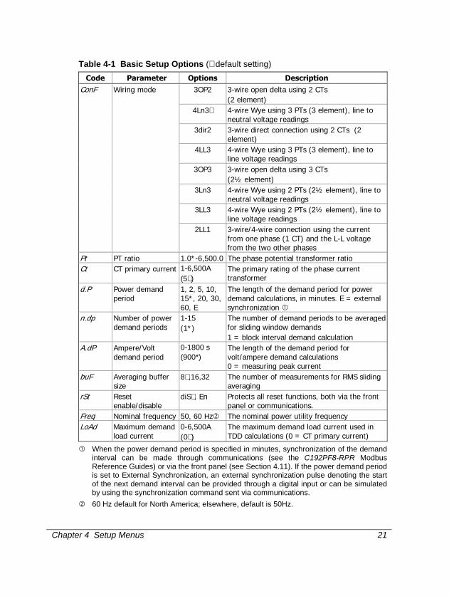
Table 4-1 Basic Setup Options (∗ default setting)
Code Parameter Options Description 3OP2 3-wire open delta using 2 CTs
(2 element) 4Ln3∗ 4-wire Wye using 3 PTs (3 element), line to
neutral voltage readings 3dir2 3-wire direct connection using 2 CTs (2
element) 4LL3 4-wire Wye using 3 PTs (3 element), line to
line voltage readings 3OP3 3-wire open delta using 3 CTs
(2½ element) 3Ln3 4-wire Wye using 2 PTs (2½ element), line to
neutral voltage readings 3LL3 4-wire Wye using 2 PTs (2½ element), line to
line voltage readings
ConF Wiring mode
2LL1 3-wire/4-wire connection using the current from one phase (1 CT) and the L-L voltage from the two other phases
Pt PT ratio 1.0*-6,500.0 The phase potential transformer ratio Ct CT primary current 1-6,500A
(5∗ ) The primary rating of the phase current transformer
d.P Power demand period
1, 2, 5, 10, 15*, 20, 30, 60, E
The length of the demand period for power demand calculations, in minutes. E = external synchronization
n.dp Number of power demand periods
1-15 (1*)
The number of demand periods to be averaged for sliding window demands 1 = block interval demand calculation
A.dP Ampere/Volt demand period
0-1800 s (900*)
The length of the demand period for volt/ampere demand calculations 0 = measuring peak current
buF Averaging buffer size
8∗ ,16,32 The number of measurements for RMS sliding averaging
rSt Reset enable/disable
diS∗ , En Protects all reset functions, both via the front panel or communications.
Freq Nominal frequency 50, 60 Hz The nominal power utility frequency LoAd Maximum demand
load current 0-6,500A (0∗ )
The maximum demand load current used in TDD calculations (0 = CT primary current)
When the power demand period is specified in minutes, synchronization of the demand interval can be made through communications (see the C192PF8-RPR Modbus Reference Guides) or via the front panel (see Section 4.11). If the power demand period is set to External Synchronization, an external synchronization pulse denoting the start of the next demand interval can be provided through a digital input or can be simulated by using the synchronization command sent via communications.
60 Hz default for North America; elsewhere, default is 50Hz.

Chapter 4 Setup Menus
22
NOTES 1) The maximum value for CT PRIMARY CURRENT × PT RATIO is 10,000,000. If this
product is greater, power related values will be zeroed.
2) Always specify WIRING MODE, PT RATIO and CT PRIMARY CURRENT prior to setting up alarm setpoints, otherwise the alarm/event setpoints which use these parameters will automatically be disabled.
3) You will not be able to change the WIRING MODE, PT RATIO and CT PRIMARY CURRENT when the PFC is in operating state (see Section 4.13).
4.2 Communications Port Setup Menu
This menu allows you to access the communications port options that the C192PF8-RPR uses to communicate with a master computer. Table 4-2 lists the communications options, their code names and applicable choices.
Activate the middle window to scroll through the list of available options, and then activate the lower window to set the option value.
To select and view a setup option: Press to activate the middle window. Use the up/down arrow keys to scroll to the desired option. The option setting will appear in the lower window.
To change the selected option: Press to activate the lower window. Press the up/down arrow keys to scroll to the desired value. Press to store the selected value or press to quit the setup menu.
Table 4-2 Communications Options (∗ default setting)
Code Parameter Options Description
Prot Communications protocol
ASCII rtu∗
ASCII protocol Modbus RTU protocol
Addr Address 0∗ -99 ASCII 1∗ -247 Modbus
Powermeter address
110 110 baud 300 300 baud 600 600 baud 1200 1200 baud 2400 2400 baud 4800 4800 baud 9600∗ 9600 baud
bAud Baud rate
19.20 19,200 baud
7E 7 bits, even parity dAtA Data format 8n 8 bits, no parity
SELECT Port
rtu Prot
SELECT CHG ENTER Port ENTER
SELECT
ENTER ESC
Chapter 4 Setup Menus 23
Code Parameter Options Description 8E∗ 8 bits, even parity
CPtb ASCII compatibility mode
diS∗ , En Disables/enables ASCII compatibility mode. For more information, see ASCII Communications Protocol Reference Guide
4.3 Digital Input Setup Menu
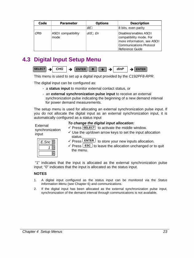
This menu is used to set up a digital input provided by the C192PF8-RPR.
The digital input can be configured as: - a status input to monitor external contact status, or - an external synchronization pulse input to receive an external
synchronization pulse indicating the beginning of a new demand interval for power demand measurements.
The setup menu is used for allocating an external synchronization pulse input. If you do not allocate the digital input as an external synchronization input, it is automatically configured as a status input
External synchronization input
To change the digital input allocation: Press to activate the middle window. Use the up/down arrow keys to set the input allocation status. Press to store your new inputs allocation. Press to leave the allocation unchanged or to quit the menu.
“1” indicates that the input is allocated as the external synchronization pulse input; “0” indicates that the input is allocated as the status input.
NOTES 1. A digital input configured as the status input can be monitored via the Status
Information Menu (see Chapter 6) and communications.
2. If the digital input has been allocated as the external synchronization pulse input, synchronization of the demand interval through communications is not available.
E.Snc
1
ENTER
SELECT
ESC
SELECT CHG dinP ENTER ENTER
Chapter 4 Setup Menus
24
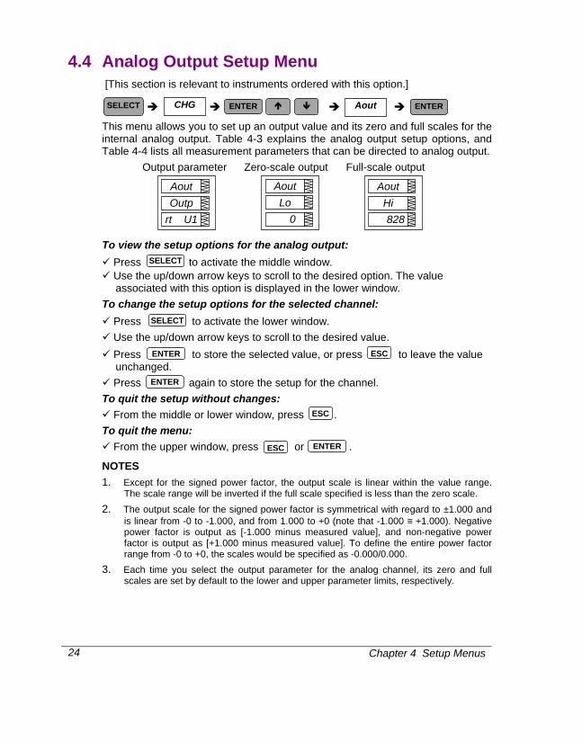
4.4 Analog Output Setup Menu [This section is relevant to instruments ordered with this option.]
This menu allows you to set up an output value and its zero and full scales for the internal analog output. Table 4-3 explains the analog output setup options, and Table 4-4 lists all measurement parameters that can be directed to analog output.
Output parameter
Zero-scale output Full-scale output
To view the setup options for the analog output: Press to activate the middle window. Use the up/down arrow keys to scroll to the desired option. The value associated with this option is displayed in the lower window.
To change the setup options for the selected channel: Press to activate the lower window. Use the up/down arrow keys to scroll to the desired value. Press to store the selected value, or press to leave the value unchanged.
Press again to store the setup for the channel. To quit the setup without changes:
From the middle or lower window, press . To quit the menu:
From the upper window, press or .
NOTES 1. Except for the signed power factor, the output scale is linear within the value range.
The scale range will be inverted if the full scale specified is less than the zero scale.
2. The output scale for the signed power factor is symmetrical with regard to ±1.000 and is linear from -0 to -1.000, and from 1.000 to +0 (note that -1.000 ≡ +1.000). Negative power factor is output as [-1.000 minus measured value], and non-negative power factor is output as [+1.000 minus measured value]. To define the entire power factor range from -0 to +0, the scales would be specified as -0.000/0.000.
3. Each time you select the output parameter for the analog channel, its zero and full scales are set by default to the lower and upper parameter limits, respectively.
SELECT CHG Aout ENTERENTER
SELECT
SELECT
ENTER ESC
ENTER
ESC
ESC ENTER
Aout
828Hi
Aout
rt U1 Outp
Aout
0 Lo

Chapter 4 Setup Menus 25
Table 4-3 Analog Output Setup Options Code Option Description
OutP Output parameter The output parameter for the analog output channel Lo Zero scale (0/4 mA) The reading of the parameter corresponding to a zero-
scale current output Hi Full scale (1/20 mA) The reading of the parameter corresponding to a full-scale
current output
Table 4-4 Analog Output Parameters Code Parameter Unit Scale
nonE Output disabled 0 Real-time Measurements
r. U 1 Voltage L1/L12 V/kV 0 to Vmax r. U 2 Voltage L2/L23 V/kV 0 to Vmax r. U 3 Voltage L3/L31 V/kV 0 to Vmax r. C1 Current L1 A 0 to Imax r. C2 Current L2 A 0 to Imax r. C3 Current L3 A 0 to Imax r. P Total kW kW/MW -Pmax to Pmax r. q Total kvar kvar/Mvar -Pmax to Pmax r. S Total kVA kVA/MVA 0 to Pmax r. PF Total PF -0.000 to 0.000 r. PF.LG Total PF lag 0 to 1.000 r. PF.Ld Total PF lead 0 to 1.000 r. Fr Frequency Hz 0 to 100.00
Average Measurements
A. U 1 Voltage L1/L12 V/kV 0 to Vmax A. U 2 Voltage L2/L23 V/kV 0 to Vmax A. U 3 Voltage L3/L31 V/kV 0 to Vmax A. C1 Current L1 A 0 to Imax A. C2 Current L2 A 0 to Imax A. C3 Current L3 A 0 to Imax A. P Total kW kW/MW -Pmax to Pmax A. q Total kvar kvar/Mvar -Pmax to Pmax A. S Total kVA kVA/MVA 0 to Pmax A. PF Total PF -0.000 to 0.000 A. PF.LG Total PF lag 0 to 1.000 A. PF.Ld Total PF lead 0 to 1.000 A. neU.C Neutral current A 0 to Imax A. Fr Frequency Hz 0 to 100.00
Present Demands
Accd.P Accumulated kW demand kW/MW 0 to Pmax Accd.S Accumulated kVA demand kVA/MVA 0 to Pmax
Imax (20% over-range) = 1.2 × CT primary current [A]
Direct wiring (PT Ratio = 1):
Chapter 4 Setup Menus
26
Vmax (690 V input option) = 828.0 V Vmax (120 V input option) = 144.0 V Pmax = (Imax × Vmax × 3) [kW x 0.001] @ wiring modes 4Ln3, 3Ln3 Pmax = (Imax × Vmax × 2) [kW x 0.001] @ wiring modes 4LL3, 3OP2, 3dir2, 3OP3, 3LL3
NOTE: Pmax is rounded to nearest whole kW units.
If Pmax is more than 9999.000 kW, it is truncated to 9999.000 kW
Wiring via PTs (PT Ratio > 1): Vmax (690 V input option) = 144 × PT Ratio [V] Vmax (120 V input option) = 144 × PT Ratio [V] Pmax = (Imax × Vmax × 3)/1000 [MW x 0.001] @ wiring modes 4Ln3, 3Ln3 Pmax = (Imax × Vmax × 2)/1000 [MW x 0.001] @ wiring modes 4LL3, 3OP2, 3dir2, 3OP3, 3LL3
NOTE: Pmax is rounded to nearest whole kW units.
The actual frequency range is 45.00 - 65.00 Hz
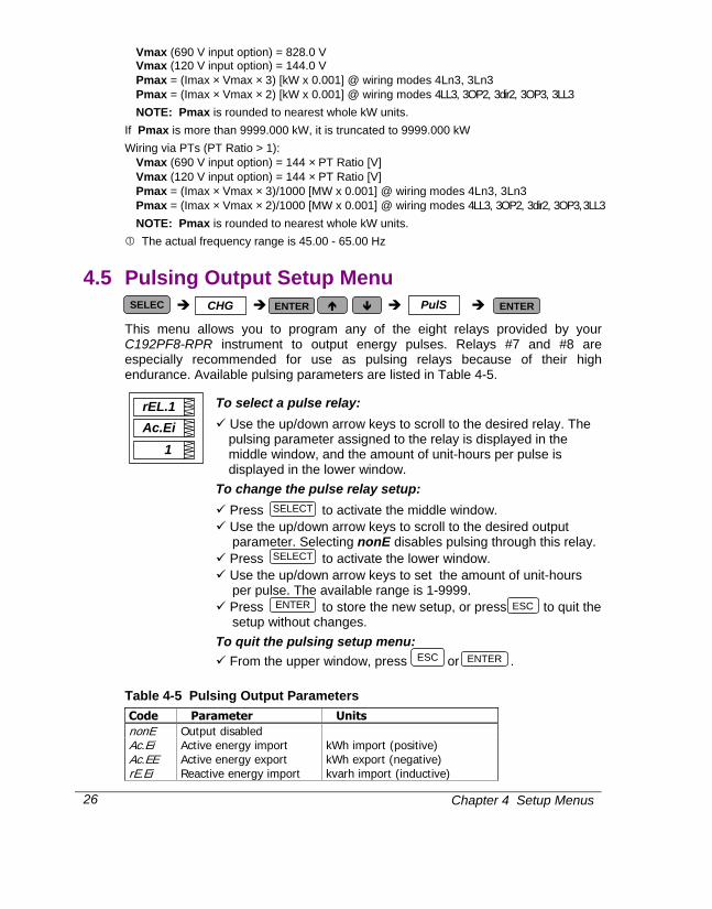
4.5 Pulsing Output Setup Menu
This menu allows you to program any of the eight relays provided by your C192PF8-RPR instrument to output energy pulses. Relays #7 and #8 are especially recommended for use as pulsing relays because of their high endurance. Available pulsing parameters are listed in Table 4-5.
To select a pulse relay:
Use the up/down arrow keys to scroll to the desired relay. The pulsing parameter assigned to the relay is displayed in the middle window, and the amount of unit-hours per pulse is displayed in the lower window.
To change the pulse relay setup: Press to activate the middle window. Use the up/down arrow keys to scroll to the desired output parameter. Selecting nonE disables pulsing through this relay.
Press to activate the lower window. Use the up/down arrow keys to set the amount of unit-hours per pulse. The available range is 1-9999.
Press to store the new setup, or press to quit the setup without changes.
To quit the pulsing setup menu: From the upper window, press or .
Table 4-5 Pulsing Output Parameters Code Parameter Units nonE Output disabled Ac.Ei Active energy import kWh import (positive) Ac.EE Active energy export kWh export (negative) rE.Ei Reactive energy import kvarh import (inductive)
SELECT
SELECT
ENTERESC
ESC ENTER
rEL.1
1 Ac.Ei
SELEC CHG PulS ENTERENTER

Chapter 4 Setup Menus 27
Code Parameter Units rE.EE Reactive energy export kvarh export (capacitive) rE.Et Reactive energy total kvarh total (absolute) AP.Et Apparent energy total kVAh total
NOTES 1. You will not be able to store your setup in the instrument if you assigned a parameter
to a relay output with a zero number of unit-hours per pulse.
2. If a relay you allocated for pulsing has been manually operated or released, it reverts automatically to normal operation.
3. If a relay you allocated for pulsing has been engaged by an alarm/event setpoint, the setpoint is automatically disabled.
4.6 Alarm/Event Setpoints Setup Menu
Your instrument provides 16 alarm/event setpoints that can monitor a wide variety of events; in turn, these events can be programmed to trigger specific actions. This menu is used to specify the events to be monitored by the setpoints, and actions to be triggered by those events.
To program a setpoint, you might need to define up to six setup parameters which include: the setpoint trigger parameter, operate and release limits, optional operate and release delays, and the setpoint action. Table 4-6 explains the setpoint setup parameters. For the entire list of available triggers and setpoint actions, refer to Tables 4-7 and 4-8.
Example: Trigger
parameter Setpoint 1 is set to monitor the real-time high current on phase 1 (the trigger parameter).
Operate limit }
}}}
Release limit }
The operate (On) and release (OFF) limits which determine setpoint operation are defined as 1200A and 1100A respectively.
SP 1
RHi.C1 triG
SP 1
1200 On
SP 1
1100 OFF
SELECT CHG SEtP ENTER ENTER

Chapter 4 Setup Menus
28
Operate delay }
} } }
Release delay }
The delays before operation (On d) and release (OFFd) are set at 5 seconds and 10 seconds respectively.
Setpoint action The action to be triggered is operation of relay #1.
To select a setpoint:
Scroll to the desired setpoint using the up/down arrow keys. To view the setup options for the setpoint:
Press to activate the middle window. Use the up/down arrow keys to scroll to the desired setup option. The value
associated with this option is displayed in the lower window. To change the selected setup option:
Press to activate the lower window. Use the up/down arrow keys to scroll to the desired value. Press to store the new value. Press to leave the value unchanged.
To store your new setup for the setpoint: From the middle window, press .
To quit the setpoint setup without changes: From the middle window, press .
To quit the setpoints setup menu: From the upper window, press or .
NOTES 1. When you enter the setpoints setup menu at the protected level, monitoring of
setpoints is temporarily suspended until you return to the main setup menu.
2. Each time you select a new trigger parameter, the operate and release limits are set by default to zero.
3. You will not be able to store your setpoint setup to the instrument if a setpoint action is directed to a relay allocated for pulsing.
4. The setpoint action directed to a relay output can be overridden using commands sent via communications. A relay can be manually operated or released. When the relay reverts to normal operation, it is automatically returned under setpoint control.
SP 1
5 On d
SP 1
10 OFFd
SP 1
rEL.1 Act
SELECT
SELECT
ENTER
ENTER
ENTER
ESC
ESC
ESC
Chapter 4 Setup Menus 29
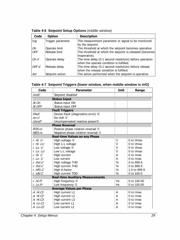
Table 4-6 Setpoint Setup Options (middle window) Code Option Description
trig Trigger parameter The measurement parameter or signal to be monitored by the setpoint.
On Operate limit The threshold at which the setpoint becomes operative. OFF Release limit The threshold at which the setpoint is released (becomes
inoperative). On d Operate delay The time delay (0.1 second resolution) before operation
when the operate condition is fulfilled. OFF d Release delay The time delay (0.1 second resolution) before release
when the release condition is fulfilled. Act Setpoint action The action performed when the setpoint is operative.
Table 4-7 Setpoint Triggers (lower window, when middle window is triG) Code Parameter Unit Range
nonE Setpoint disabled Status Input St.On Status input ON St.OFF Status input OFF Fault Triggers FAult Device Fault (diagnostics error) no-U No-Volt UncoP Uncompensated reactive power Phase Reversal POS.ro. Positive phase rotation reversal NEG.ro. Negative phase rotation reversal Real-time Values on any Phase r. Hi. U High voltage V 0 to Vmax r. Hi. LU High L-L voltage V 0 to Vmax r. Lo. U Low voltage V 0 to Vmax r. Lo. LU Low L-L voltage V 0 to Vmax r. Hi. C High current A 0 to Imax r. Lo. C Low current A 0 to Imax r. thd.U High voltage THD % 0 to 999.9 r. thd.C High current THD % 0 to 999.9 r. HFc.C High K-factor % 1.0 to 999.9 r. tdd.C High current TDD % 0 to 100.0 Real-time Auxiliary Measurements r. Hi.Fr High frequency Hz 0 to 100.00 r. Lo.Fr Low frequency Hz 0 to 100.00 Average Values per Phase A. Hi.C1 High current L1 A 0 to Imax A. Hi.C2 High current L2 A 0 to Imax A. Hi.C3 High current L3 A 0 to Imax A. Lo.C1 Low current L1 A 0 to Imax A. Lo.C2 Low current L2 A 0 to Imax
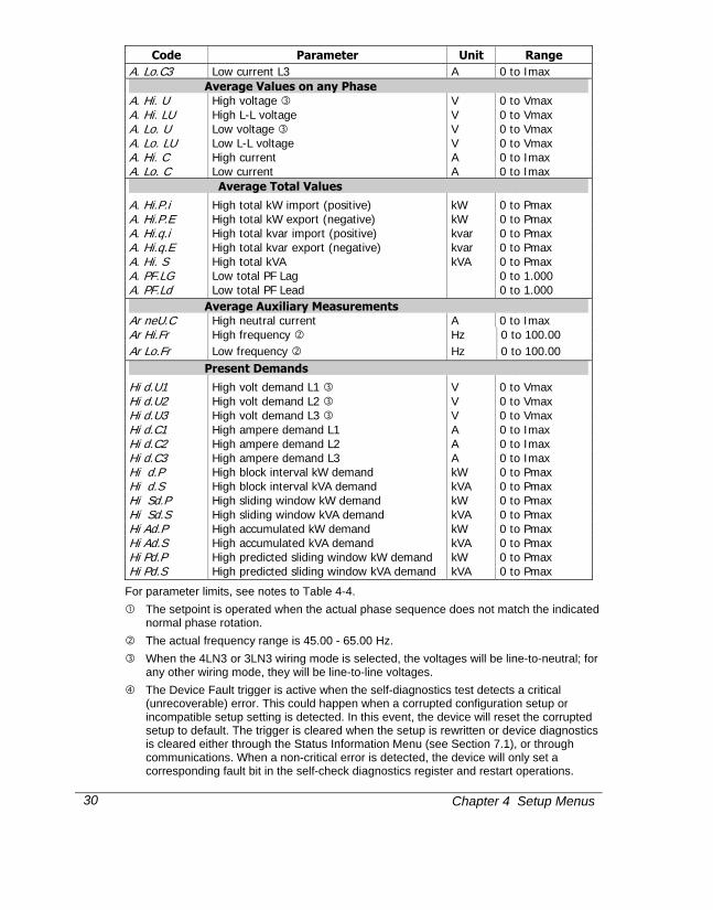
Chapter 4 Setup Menus
30
Code Parameter Unit Range A. Lo.C3 Low current L3 A 0 to Imax Average Values on any Phase A. Hi. U High voltage V 0 to Vmax A. Hi. LU High L-L voltage V 0 to Vmax A. Lo. U Low voltage V 0 to Vmax A. Lo. LU Low L-L voltage V 0 to Vmax A. Hi. C High current A 0 to Imax A. Lo. C Low current A 0 to Imax
Average Total Values
A. Hi.P.i High total kW import (positive) kW 0 to Pmax A. Hi.P.E High total kW export (negative) kW 0 to Pmax A. Hi.q.i High total kvar import (positive) kvar 0 to Pmax A. Hi.q.E High total kvar export (negative) kvar 0 to Pmax A. Hi. S High total kVA kVA 0 to Pmax A. PF.LG Low total PF Lag 0 to 1.000 A. PF.Ld Low total PF Lead 0 to 1.000 Average Auxiliary Measurements Ar neU.C High neutral current A 0 to Imax Ar Hi.Fr High frequency Hz 0 to 100.00 Ar Lo.Fr Low frequency Hz 0 to 100.00 Present Demands
Hi d.U1 High volt demand L1 V 0 to Vmax Hi d.U2 High volt demand L2 V 0 to Vmax Hi d.U3 High volt demand L3 V 0 to Vmax Hi d.C1 High ampere demand L1 A 0 to Imax Hi d.C2 High ampere demand L2 A 0 to Imax Hi d.C3 High ampere demand L3 A 0 to Imax Hi d.P High block interval kW demand kW 0 to Pmax Hi d.S High block interval kVA demand kVA 0 to Pmax Hi Sd.P High sliding window kW demand kW 0 to Pmax Hi Sd.S High sliding window kVA demand kVA 0 to Pmax Hi Ad.P High accumulated kW demand kW 0 to Pmax Hi Ad.S High accumulated kVA demand kVA 0 to Pmax Hi Pd.P High predicted sliding window kW demand kW 0 to Pmax Hi Pd.S High predicted sliding window kVA demand kVA 0 to Pmax
For parameter limits, see notes to Table 4-4.
The setpoint is operated when the actual phase sequence does not match the indicated normal phase rotation.
The actual frequency range is 45.00 - 65.00 Hz.
When the 4LN3 or 3LN3 wiring mode is selected, the voltages will be line-to-neutral; for any other wiring mode, they will be line-to-line voltages.
The Device Fault trigger is active when the self-diagnostics test detects a critical (unrecoverable) error. This could happen when a corrupted configuration setup or incompatible setup setting is detected. In this event, the device will reset the corrupted setup to default. The trigger is cleared when the setup is rewritten or device diagnostics is cleared either through the Status Information Menu (see Section 7.1), or through communications. When a non-critical error is detected, the device will only set a corresponding fault bit in the self-check diagnostics register and restart operations.
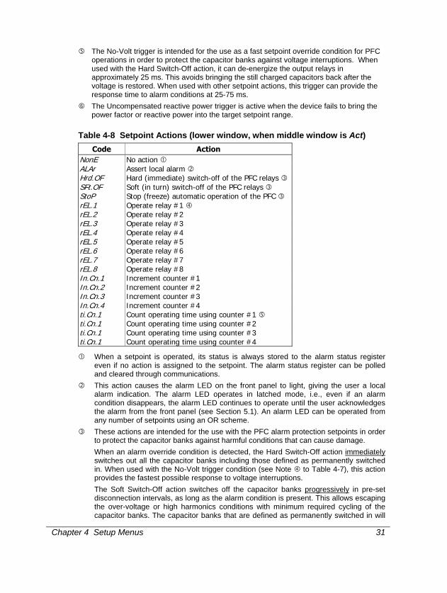
Chapter 4 Setup Menus 31
The No-Volt trigger is intended for the use as a fast setpoint override condition for PFC operations in order to protect the capacitor banks against voltage interruptions. When used with the Hard Switch-Off action, it can de-energize the output relays in approximately 25 ms. This avoids bringing the still charged capacitors back after the voltage is restored. When used with other setpoint actions, this trigger can provide the response time to alarm conditions at 25-75 ms.
The Uncompensated reactive power trigger is active when the device fails to bring the power factor or reactive power into the target setpoint range.
Table 4-8 Setpoint Actions (lower window, when middle window is Act) Code Action
NonE No action ALAr Assert local alarm Hrd.OF Hard (immediate) switch-off of the PFC relays SFt.OF Soft (in turn) switch-off of the PFC relays StoP Stop (freeze) automatic operation of the PFC rEL.1 Operate relay #1 rEL.2 Operate relay #2 rEL.3 Operate relay #3 rEL.4 Operate relay #4 rEL.5 Operate relay #5 rEL.6 Operate relay #6 rEL.7 Operate relay #7 rEL.8 Operate relay #8 In.Cn.1 Increment counter #1 In.Cn.2 Increment counter #2 In.Cn.3 Increment counter #3 In.Cn.4 Increment counter #4 ti.Cn.1 Count operating time using counter #1 ti.Cn.1 Count operating time using counter #2 ti.Cn.1 Count operating time using counter #3 ti.Cn.1 Count operating time using counter #4
When a setpoint is operated, its status is always stored to the alarm status register even if no action is assigned to the setpoint. The alarm status register can be polled and cleared through communications.
This action causes the alarm LED on the front panel to light, giving the user a local alarm indication. The alarm LED operates in latched mode, i.e., even if an alarm condition disappears, the alarm LED continues to operate until the user acknowledges the alarm from the front panel (see Section 5.1). An alarm LED can be operated from any number of setpoints using an OR scheme.
These actions are intended for the use with the PFC alarm protection setpoints in order to protect the capacitor banks against harmful conditions that can cause damage.
When an alarm override condition is detected, the Hard Switch-Off action immediately switches out all the capacitor banks including those defined as permanently switched in. When used with the No-Volt trigger condition (see Note to Table 4-7), this action provides the fastest possible response to voltage interruptions.
The Soft Switch-Off action switches off the capacitor banks progressively in pre-set disconnection intervals, as long as the alarm condition is present. This allows escaping the over-voltage or high harmonics conditions with minimum required cycling of the capacitor banks. The capacitor banks that are defined as permanently switched in will
Chapter 4 Setup Menus
32
not be affected. After the alarm condition passes, the PFC will return to automatic operation after the safety delay which is 50 times the power factor setpoint operate delay (see Note to Table 4-11).
The Stop action freezes the PFC operations in automatic operation modes. The PFC avoids any automatic switching operations on the capacitor banks while the alarm condition is present. This action does not affect operations in the Manual/Remote mode.
Alarm relays operate in unlatched mode. This means that a relay is operated while an alarm condition is present and is automatically released when an alarm condition disappears. Each relay can be operated from any number of setpoints using an OR scheme, i.e., a relay will be operative while either of the alarm conditions is still present.
This action converts a common-use event counter to the dedicated time counter that measures time at 0.1-hour resolution while the setpoint is operative. Each time counter has a non-volatile shadow counter that counts time at 1-second resolution before the corresponding time counter is incremented. The time counters can be inspected via the Status Information Menu. They are labeled by an hour mark in the middle window.
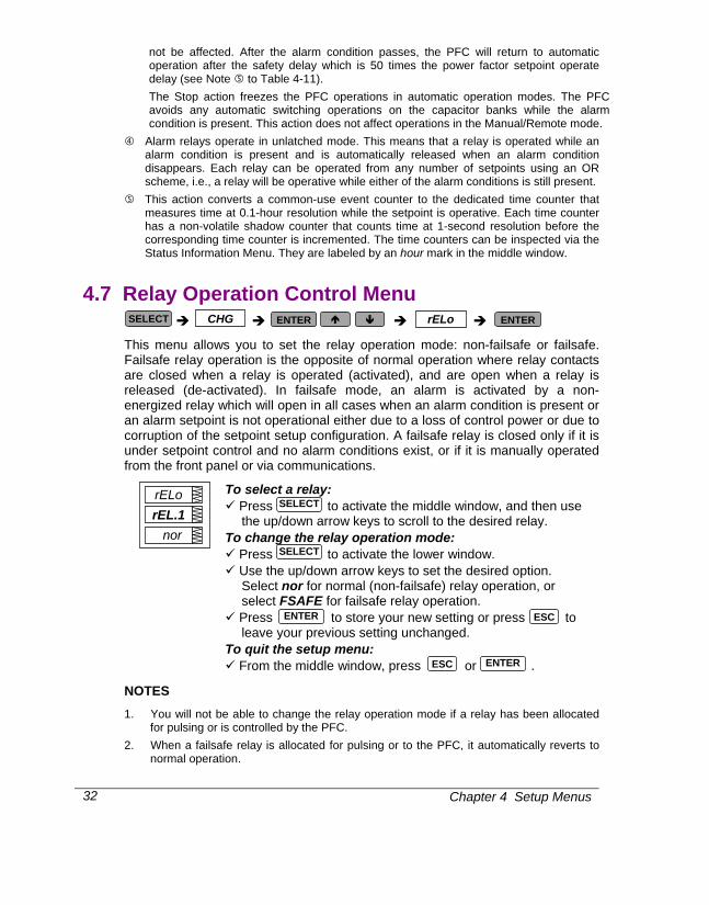
4.7 Relay Operation Control Menu
This menu allows you to set the relay operation mode: non-failsafe or failsafe. Failsafe relay operation is the opposite of normal operation where relay contacts are closed when a relay is operated (activated), and are open when a relay is released (de-activated). In failsafe mode, an alarm is activated by a non-energized relay which will open in all cases when an alarm condition is present or an alarm setpoint is not operational either due to a loss of control power or due to corruption of the setpoint setup configuration. A failsafe relay is closed only if it is under setpoint control and no alarm conditions exist, or if it is manually operated from the front panel or via communications.
To select a relay: Press to activate the middle window, and then use the up/down arrow keys to scroll to the desired relay.
To change the relay operation mode: Press to activate the lower window. Use the up/down arrow keys to set the desired option. Select nor for normal (non-failsafe) relay operation, or select FSAFE for failsafe relay operation.
Press to store your new setting or press to leave your previous setting unchanged.
To quit the setup menu: From the middle window, press or .
NOTES 1. You will not be able to change the relay operation mode if a relay has been allocated
for pulsing or is controlled by the PFC.
2. When a failsafe relay is allocated for pulsing or to the PFC, it automatically reverts to normal operation.
rELo
nor rEL.1
SELECT CHG rELo ENTERENTER
SELECT
SELECT
ENTER
ENTER
ESC
ESC

Chapter 4 Setup Menus 33
4.8 Display Setup Menu
This menu allows you to view and change display properties. Table 4-9 lists available options with their code names and applicable ranges.
Table 4-9 Display Options (∗ default setting)
Display Code Parameter Options Description UPdt
Display update time
0.1 - 10.0 s (0.5)*
Defines interval between display updates
ScrL
Auto scroll nonE* 2-15 s
Disables/enables auto scroll on common measurements display (main screen) and defines scroll interval
rEtn
Auto return to the main screen
diS*, En Disables/enables auto return to the main screen after 30 seconds of uninterrupted use
Ph.P
Phase powers display mode
diS*, En Disables/enables display of phase powers in common measurements (main screen)
Fund
Fundamental values display mode
diS*, En Disables/enables display of fundamental values in common measurements (main screen)
SELECT CHG diSP ENTER ENTER
diSP
5
ScrL
diSP
0.5
UPdt
diSP
diS
Ph.P
diSP
diS
rEtn
diSP
diS
Fund
Chapter 4 Setup Menus
34
To select a display option: Press to activate the middle window, and then use the up/down arrow keys to scroll to the desired option.
To change the display option: Press to activate the lower window. Use the up/down arrow keys to set the desired option. Press to store your new setting or press to leave your previous setting unchanged.
To quit the display setup menu: From the middle window, press or .
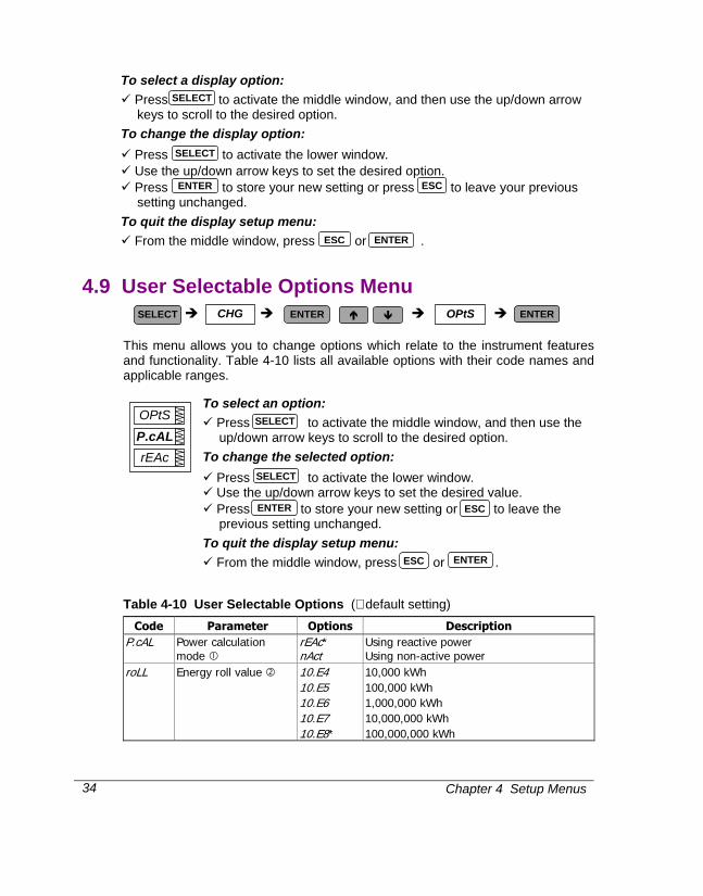
4.9 User Selectable Options Menu
This menu allows you to change options which relate to the instrument features and functionality. Table 4-10 lists all available options with their code names and applicable ranges.
To select an option: Press to activate the middle window, and then use the up/down arrow keys to scroll to the desired option.
To change the selected option: Press to activate the lower window. Use the up/down arrow keys to set the desired value. Press to store your new setting or to leave the previous setting unchanged.
To quit the display setup menu: From the middle window, press or .
Table 4-10 User Selectable Options (∗ default setting) Code Parameter Options Description
P.cAL Power calculation mode
rEAc* nAct
Using reactive power Using non-active power
roLL Energy roll value 10.E4 10.E5 10.E6 10.E7 10.E8*
10,000 kWh 100,000 kWh 1,000,000 kWh 10,000,000 kWh 100,000,000 kWh
SELECT
SELECT
OPtS
rEAc P.cAL
ENTER ESC
ESC ENTER
SELECT CHG OPtS ENTERENTER
SELECT
SELECT
ESC
ESC ENTER
ENTER

Chapter 4 Setup Menus 35
Code Parameter Options Description Ph.En Phase energy
measurements diS*, En Enables/disables measurements of energies
per phase
Power calculation mode (P.cAL):
Mode 1: Reactive power calculation (rEAc)
Active power P and reactive power Q are measured directly and apparent power
S = √ P2 + Q2
Mode 2: Non-active power calculation (nAct)
Active power is measured directly, apparent power S = V × I (where V, I - rms voltage and currents) and non-active power N = √ S2 - P2
Mode 1 is recommended for electrical networks with low harmonic distortion (voltage THD < 5%, current THD < 10%); Mode 2 is recommended for all other cases.
Energy roll value example: If roll value = 10.E4, the energy counter contains 4 digits, i.e., energy is displayed up to 9.999 MWh (Mvarh, MVAh) with resolution 0.001 MWh.
Rollover Value
Maximum Energy kWh (kvarh, kVAh)
Maximum Display Reading MWh (Mvarh, MVAh)
Display Resolution MWh (Mvarh, MVAh)
10.E4 9,999 9.999 0.001 10.E5 99,999 99.999 0.001 10.E6 999,999 999.99 0.01 10.E7 9,999,999 9,999.9 0.1 10.E8 99,999,999 99,999 1
The roll value may be changed in accordance with the average load of the power line. For example, if average power is 400 kW and the counter must be reset every 3 months (2160 hours), then energy during this period equals 864000 kWh (6 digits) and the roll value = 10.E6.
Chapter 4 Setup Menus
36
4.10 Access Control Menu
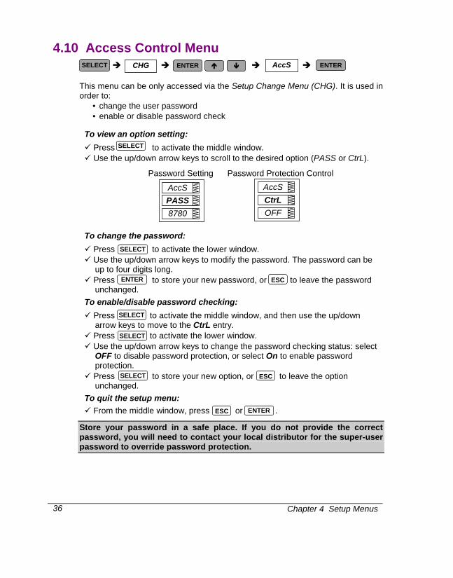
This menu can be only accessed via the Setup Change Menu (CHG). It is used in order to:
• change the user password • enable or disable password check
To view an option setting: Press to activate the middle window. Use the up/down arrow keys to scroll to the desired option (PASS or CtrL).
Password Setting Password Protection Control
To change the password: Press to activate the lower window. Use the up/down arrow keys to modify the password. The password can be up to four digits long.
Press to store your new password, or to leave the password unchanged.
To enable/disable password checking: Press to activate the middle window, and then use the up/down arrow keys to move to the CtrL entry.
Press to activate the lower window. Use the up/down arrow keys to change the password checking status: select OFF to disable password protection, or select On to enable password protection.
Press to store your new option, or to leave the option unchanged.
To quit the setup menu: From the middle window, press or .
Store your password in a safe place. If you do not provide the correct password, you will need to contact your local distributor for the super-user password to override password protection.
SELECT CHG AccS ENTERENTER
SELECT
SELECT
SELECT
SELECT
AccS
8780
PASSAccS
OFF CtrL
ENTER ESC
SELECT ESC
ESC ENTER

Chapter 4 Setup Menus 37
4.11 Reset/Synchronization Menu
This menu allows you to reset to zero the accumulators and Min/Max registers in your instrument, and also to synchronize the power demand interval. The menu can be only accessed via the Setup Change Menu (CHG). If the reset is disabled from the Basic Setup Menu (see Section 4.1), you will not be able to enter this menu.
The following designations are used to specify a data location to be affected: EnrG Resets total accumulated energies
dnd Resets all total maximum demands
P.dnd Resets total power maximum demands
A.dnd Resets volt/ampere maximum demands
Lo.Hi Resets Min/Max registers (does not affect maximum demands) Cnt Resets all event/time counters
Cnt.1 Resets event/time counter # 1
Cnt.2 Resets event/time counter # 2
Cnt.3 Resets event/time counter # 3
Cnt.4 Resets event/time counter # 4
CYC Resets all PFC relay operation (banks switching cycle) counters
CYC.1 Resets PFC relay operation counter # 1
CYC.2 Resets PFC relay operation counter # 2
CYC.3 Resets PFC relay operation counter # 3
CYC.4 Resets PFC relay operation counter # 4
CYC.5 Resets PFC relay operation counter # 5
CYC.6 Resets PFC relay operation counter # 6
CYC.7 Resets PFC relay operation counter # 7
CYC.8 Resets PFC relay operation counter # 8
d.Snc Provides synchronization of the power demand interval (see NOTES below)
To reset the desired locations: Press to activate the middle window, and then use the up/down arrow keys to scroll to the desired data location entry.
Press to activate the lower window. Press and hold for about 5 seconds until the do label is replaced with done, and then release the key. You will return to the middle window.
Press to quit the menu.
NOTES: 1. If changing data in the instrument via the front panel is not secured by a password, fast
reset of the Min/Max registers, maximum demands and energies can be done from the
SELECT CHG rSt ENTER ENTER
SELECT
SELECT
ENTER
rSt
do
EnrG
ESC

Chapter 4 Setup Menus
38
data display mode (see Section 5.1), and reset of counters from the Status Information Menu (see Section 6.1) without entering the reset menu.
2. If you select the d.Snc entry, take into consideration the following:
a) If the power demand period is specified in minutes (see Section 4.1, Basic Setup Options), this action provides synchronization of the instrument’s internal timer. If the time expired from the beginning of the current demand interval is more then 30 seconds, the new demand interval starts immediately, otherwise synchronization is delayed until the next demand interval.
b) The synchronization is made at the moment delayed by exactly 5 seconds from the time you first pressed while you hold the key.
4.12 Manual Relay Control Menu
This menu allows you to manually activate (force operated) or de-activate (force released) a relay if it is not allocated for pulsing and not controlled by the PFC. When a relay is controlled by the alarm setpoint, this command will override the setpoint alarm conditions until the relay is returned to normal operation.
To select a relay: Press to activate the middle window, and then use the up/down arrow keys to scroll to the desired relay.
To change the relay status: Press to activate the lower window. Use the up/down arrow keys to set the desired option. Select nor for normal (setpoint-controlled) relay operation, select OPEr to activate a relay, or rELS to de-activate a relay.
Press to store your new setting or press to leave your previous setting unchanged.
To quit the setup menu: From the middle window, press or .
NOTE You will not be able to override the relay operation mode if a relay has been allocated for pulsing or is controlled by the PFC.
ENTER
rELc
OPEr rEL.1
SELECT CHG rELc ENTERENTER
SELECT
SELECT
ENTER
ENTER
ESC
ESC
Chapter 4 Setup Menus 39
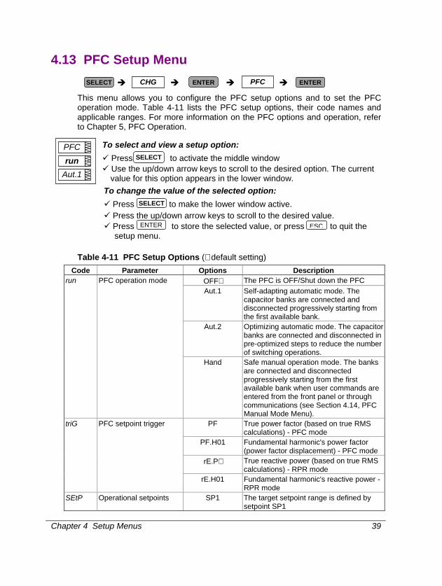
4.13 PFC Setup Menu
This menu allows you to configure the PFC setup options and to set the PFC operation mode. Table 4-11 lists the PFC setup options, their code names and applicable ranges. For more information on the PFC options and operation, refer to Chapter 5, PFC Operation.
To select and view a setup option: Press to activate the middle window Use the up/down arrow keys to scroll to the desired option. The current value for this option appears in the lower window.
To change the value of the selected option: Press to make the lower window active. Press the up/down arrow keys to scroll to the desired value. Press to store the selected value, or press to quit the setup menu.
Table 4-11 PFC Setup Options (∗ default setting)
Code Parameter Options Description OFF∗ The PFC is OFF/Shut down the PFC Aut.1 Self-adapting automatic mode. The
capacitor banks are connected and disconnected progressively starting from the first available bank.
Aut.2 Optimizing automatic mode. The capacitor banks are connected and disconnected in pre-optimized steps to reduce the number of switching operations.
run PFC operation mode
Hand Safe manual operation mode. The banks are connected and disconnected progressively starting from the first available bank when user commands are entered from the front panel or through communications (see Section 4.14, PFC Manual Mode Menu).
PF True power factor (based on true RMS calculations) - PFC mode
PF.H01 Fundamental harmonic's power factor (power factor displacement) - PFC mode
rE.P∗ True reactive power (based on true RMS calculations) - RPR mode
triG PFC setpoint trigger
rE.H01 Fundamental harmonic's reactive power - RPR mode
SEtP Operational setpoints SP1 The target setpoint range is defined by setpoint SP1
SELECT
SELECT
PFC
Aut.1 run
SELECT CHG ENTER PFC ENTER
ENTER ESC

Chapter 4 Setup Menus
40
Code Parameter Options Description SP1-2∗ Two target setpoint ranges are defined by
setpoints SP1 and SP2 (generally, to differentiate between day and night operations). The active setpoint range is selected through a digital (status) input.
U.CAP Nominal voltage of the capacitor banks
0∗ , 1V to 999V, 0.01kV to
99.99kV
1V to 999V if PT RATIO = 1 0.01kV to 99.99 kV if PT RATIO > 1 0 = disable automatic adjustment of the capacitor bank powers to the measured line voltage (assuming that those have been adjusted manually)
L.PF1 Low target PF1 (in PFC mode)
0.500 to -0.500
Low target power factor for setpoint SP1
H.PF1 High target PF1 (in PFC mode)
0.500 to -0.500
High target power factor for setpoint SP1
L.PF2 Low target PF2 (in PFC mode)
0.500 to -0.500
Low target power factor for setpoint SP2
H.PF2 High target PF2 (in PFC mode)
0.500 to -0.500
High target power factor for setpoint SP2
L.rE1 Low target kvar 1 (in RPR mode)
-10000 to 10000(-750)
Low target kvar for setpoint SP1
H.rE1 High target kvar 1 (in RPR mode)
-10000 to 10000(1200)
High target kvar for setpoint SP1
L.rE2 Low target kvar 2 (in RPR mode)
-10000 to 10000(-750)
Low target kvar for setpoint SP2
H.rE2 High target kvar 2 (in RPR mode)
-10000 to 10000(1200)
High target kvar for setpoint SP2
OP.d Setpoint operate delay, sec
1 to 3600 s (3∗ ) The amount of time that the power factor must be continuously outside the setpoint range in order to run the automatic power factor correction
On.d Switch-on time (connection interval), sec
3 to 3600 s (600∗ )
The amount of idling time after a capacitor bank switches in, when further switching operations are prohibited
OFF.d Switch-off time (disconnection interval), sec
3 to 3600 s (600∗ )
The amount of idling time after a capacitor bank switches out, when further switching operations are prohibited
rEc.d Re-connection (discharge) time, sec
5 to 3600 s (300∗ )
The capacitor bank reclose delay to allow the capacitors to discharge after disconnecting
CAP1 Size of the capacitor bank #1, kvar
On, nonE, 1 to 10000 kvar
(1500∗ )
Power rating of the capacitor bank. nonE = not used, On = permanently switched in
CAP2 Size of the capacitor bank #2, kvar
On, nonE, 1 to 10000 kvar
(1500∗ )
Power rating of the capacitor bank. nonE = not used, On = permanently switched in
Chapter 4 Setup Menus 41
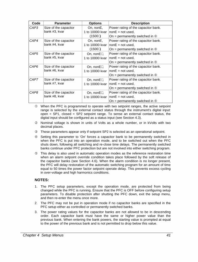
Code Parameter Options Description CAP3 Size of the capacitor
bank #3, kvar On, nonE,
1 to 10000 kvar (1500∗ )
Power rating of the capacitor bank. nonE = not used, On = permanently switched in
CAP4 Size of the capacitor bank #4, kvar
On, nonE, 1 to 10000 kvar
(1500∗ )
Power rating of the capacitor bank. nonE = not used, On = permanently switched in
CAP5 Size of the capacitor bank #5, kvar
On, nonE∗ , 1 to 10000 kvar
Power rating of the capacitor bank. nonE = not used, On = permanently switched in
CAP6 Size of the capacitor bank #6, kvar
On, nonE∗ , 1 to 10000 kvar
Power rating of the capacitor bank. nonE = not used, On = permanently switched in
CAP7 Size of the capacitor bank #7, kvar
On, nonE∗ , 1 to 10000 kvar
Power rating of the capacitor bank. nonE = not used, On = permanently switched in
CAP8 Size of the capacitor bank #8, kvar
On, nonE∗ , 1 to 10000 kvar
Power rating of the capacitor bank. nonE = not used, On = permanently switched in
When the PFC is programmed to operate with two setpoint ranges, the active setpoint range is selected by the external contact status through the instrument's digital input: open = SP1, closed = SP2 setpoint range. To sense an external contact status, the digital input should be configured as a status input (see Section 4.3).
Nominal voltage is shown in units of Volts as a whole number, or in kVolts with two decimal places.
These parameters appear only if setpoint SP2 is selected as an operational setpoint. Setting this parameter to 'On' forces a capacitor bank to be permanently switched in
when the PFC is put into an operation mode, and to be switched out when the PFC shuts down, following all switching and re-close time delays. The permanently switched banks continue under PFC protection but are not involved into either switching program.
This delay is also used in automatic operation modes as the reference restoration time when an alarm setpoint override condition takes place followed by the soft release of the capacitor banks (see Section 4.6). When the alarm condition is no longer present, the PFC will delay restoration of the automatic switching program for an amount of time equal to 50 times the power factor setpoint operate delay. This prevents excess cycling in over-voltage and high harmonics conditions.
NOTES: 1. The PFC setup parameters, except the operation mode, are protected from being
changed while the PFC is running. Ensure that the PFC is OFF before configuring setup parameters. To disable protection after shutting the PFC down, exit the setup menu, and then re-enter the menu once more.
2. The PFC may not be put in operation mode if no capacitor banks are specified in the PFC setup either as controlled or permanently switched banks.
3. The power rating values for the capacitor banks are not allowed to be in descending order. Each capacitor bank must have the same or higher power value than the previous bank. When entering the bank powers, the starting value is prompted at equal to the power of the previous bank and is not permitted to drop below this value.

Chapter 4 Setup Menus
42
4. The target power factor limits are always specified for the I and IV quadrants regardless of the location of the instrument on the source or load side. The PFC will automatically account for the direction of power flow providing full four-quadrant operation.
5. If both target power factor limits are specified for the same quadrant, the high power factor limit should never be less than the low limit. If the target limits are being set for two quadrants, the lagging (inductive) power factor should be specified as the low limit and the leading (capacitive) one as the high target limit. Whenever these relations are not fulfilled, the instrument will automatically adjust the high target power factor to the low target limit.

Chapter 4 Setup Menus 43
4.14 PFC Manual Mode Menu
This menu allows you to manually operate (connect or disconnect) the PFC capacitor banks in progressive order by entering commands from the front panel. The menu can be only accessed via the Setup Change Menu (CHG) if the PFC is running in Manual Mode (see Section 4.13, PFC Setup).
When in the Manual Mode menu, the present measured power factor value is displayed in the upper window, the PFC operation status in the flashing middle window and measured reactive power in the lower window. Depending on the selected power factor setpoint trigger, the power factor and reactive power are based on the true RMS measurements or on the fundamental harmonic values. The PFC operation status reported in the middle window is explained in Table 4-12.
The up/down arrow keys are used as the command keys and act in Manual Mode as follows:
Switches in a capacitor bank
Switches out a capacitor bank
The capacitor banks are connected and disconnected progressively from the first controlled bank to the last, following all pre-set switching and re-connection delays. Whenever a number of the banks with the same size are available, the PFC will use at each step the bank that has the minimum number of switching cycles. A new command will not be accepted until the PFC has completed the previous command, i.e., until the reported PFC operation status is Ready, Full or Idle.
To switch in a capacitor bank: Ensure that the PFC is ready, and then press and release the up
arrow key. To switch out a capacitor bank:
Ensure that the PFC is ready, and then press and release the down arrow key.
To quit the menu: Press or .
Table 4-12 PFC Operation Status Code Operation Status Description rdY Ready A switching program is complete
ALAr Alarm Operations are stopped by an alarm setpoint buSY Busy Waiting until a switching delay is expired FULL Full All capacitor banks are switched in IdLE Idle All capacitor banks are switched out
NOTE The Manual Mode commands do not affect the capacitor banks that are defined as permanently switched banks. These always switch in automatically when the PFC is put into operation, including in Manual Mode.
0.980
124.5 rdY
SELECT CHG ENTER PFC.H ENTER
ENTER ESC
Chapter 5 PFC Setup and Operation
44
Chapter 5 PFC Setup and Operation 5. PFC Setup and Operation
This chapter describes how to setup the Power Factor Controller for your application and explains its important features. Brief instructions are included for certain setup and display operations. Complete setup instructions are found in Section 4.13, PFC Setup; complete display information is found in Chapter 6 (Data Display) and Chapter 7 (Viewing Status Information).
5.1 Capacitor Bank Control Options The C192PF8-RPR offers you three options to control capacitor banks in order to meet the conditions of your electrical equipment and avoid unnecessary switching. All options may be used at the same time when applied to different banks.
Automatic Control This option puts the banks under full PFC control and allows them to be used in either a manual or automatic PFC switching program. To put the capacitor bank under PFC control, specify the bank size in kvar to allow for manual or automatic bank switching (see Section 4.13, PFC Setup).
Manual Control This option allows some of the banks to be manually switched in using direct control over the output relays. You can use this option for checking or repairing capacitor banks.
This option does not use the PFC to control the capacitor banks. Switching is done outside the PFC by directly forcing the output relays from the front panel (see Section 4.12, Manual Relay Control Menu) or via communications. The switched in banks remain connected until they are disconnected manually.
The size of the capacitor banks intended for direct manual control should be set to none (see Section 4.13, PFC Setup), thus moving them out of the PFC control.
Since the PFC does not manage the capacitor banks, and forcing the output relays also overrides the common alarm setpoint conditions, neither PFC setpoint protection nor common alarm setpoints can be used to protect the capacitor banks against harmful alarm conditions. This should be done separately, outside the C192PF8-RPR.
Permanently Switched (Non-Programmable) Banks This option allows some of the banks to be automatically switched in whenever the PFC is put into operation and to remain permanently connected any time the PFC is operating. This option is intended to avoid excess cycling of the capacitor banks that draw near their cycling limit, or to put constant capacitive load onto the network to avoid non-necessary switching.

Chapter 5 PFC Setup and Operation 45
To specify the bank as a permanently switched bank, set the bank size parameter to On (see Section 4.13, PFC Setup).
The permanently switched banks are switched in automatically when the PFC is put into either manual or automatic operation mode and before a switching program begins, and are switched out when the PFC shuts down, following all switching and re-connection time delays. These banks remain under PFC protection but are not involved into either switching program (assumed to be non-programmable banks).
5.2 PFC Operation
5.2.1 Modes of Operation The PFC can operate in three control modes: self-adapting automatic mode, optimizing automatic mode, and manual mode. Both automatic modes provide automatic power factor (in Power Factor Controller mode) or reactive power (in Reactive Power Regulator mode) correction whereby the PFC automatically accounts for deficient or excessive reactive power and makes necessary adjustments.
Self-adapting Automatic Mode (Auto 1) Self-adapting mode is a simple automatic operation mode suitable to most applications. The PFC switches in additional banks when the measured power factor lags against the target power factor or the measured reactive power is over the high target kvar (excessive inductive load is detected), and switches out redundant banks when the measured power factor leads against the target power factor limits or the measured reactive power is under the low target kvar (excessive capacitive load is detected).
The capacitor banks are switched in and switched out progressively, always starting from the low-size bank available at this step, following the pre-set switching and re-connection delays.
The self-adapting program is complete when one of the following is true: 1. The measured power factor (in PFC mode) or kvar (in RPR mode) attains the
pre-set PFC setpoint range. 2. In PFC mode, the deviation from the target power factor is less than 0.7 of
the smallest size bank.
Automatic Optimization Mode (Auto 2) This is a highly optimized operation mode that provides minimum switching operations. At each step, the PFC accounts for deficient inductive or capacitive reactive power to attain the target power factor or target kvar and selects the exact combination of the banks among those presently available that requires the minimum number of switching operations.
Whenever no combination is found that allows achieving the target setpoint range, the PFC will select a combination that provides minimum deviation from

Chapter 5 PFC Setup and Operation
46
the target. When no leading (capacitive) target power factor is allowed, only combinations that provide lagging (inductive) power factor will be checked.
The banks are connected and disconnected starting from the low-size banks, following all pre-set switching and re-connection delays. Alternation of switching operations is provided when needed to avoid excessive deviation from the target power factor.
The optimization program is complete when one of the following is true: 1. The measured power factor (in PFC mode) or kvar (in RPR mode) attains the
pre-set PFC setpoint range. 2. In PFC mode, the deviation from the target power factor is less than 0.7 of
the lowest-size bank. 3. The optimal combination may not be achieved. The controlled power factor
or kvar is brought to the value that is as close as possible to the target.
Manual Mode This mode can be used for manual adjustment of the power factor or kvar and for testing purposes. In manual operation mode, power factor or kvar correction is triggered by user commands entered from the front panel (see Section 4.14, PFC Manual Mode Menu) or through communications. Each command switches in or switches out a single capacitor bank. When there are no banks that can be operated or an alarm condition is present, the user command is discarded.
The banks are switched in and switched out progressively, always starting from the lowest-size bank available, following the pre-set switching and re-connection delays.
Manual Mode is a safe, fully protected operation mode provided that the setpoint protection overrides especially dedicated to the PFC are also operational here. Whenever the capacitor banks are protected through the alarm setpoints and an alarm override condition is present, the manual command will be overridden resulting in immediate or soft switch-off of the capacitor banks.
Changing the Operation Mode From the PFC setup menu (see Section 4.13, PFC Setup), set the operation mode parameter to the desired mode. This entry is always enabled unless the PFC is in Shut Down mode.
Changing from one operation mode to another mode can be done while the PFC is running, with no need to shut it down. The new program will start immediately from the present point achieved. No extra cycling will be made if the previous automatic program was completed. Changing to Manual Mode will stop all switching operations.
After changing to an automatic mode, the disconnected capacitor banks will be put into operation after the full discharge time.
The PFC setup options (as well as certain basic configuration options) may not be changed while the PFC is running.

Chapter 5 PFC Setup and Operation 47
Shutting the PFC Down From the PFC setup menu, set the PFC operation mode to OFF. This will put the PFC into Shut Down mode.
Shut Down mode provides step-by-step disconnection of all the capacitor banks that are under the PFC control. The banks switch out progressively, following disconnection intervals (switch-off delays). After all the banks are switched out, the PFC is put into OFF state.
5.2.2 PFC Setpoints The PFC can operate in Power Factor Controller (PFC) mode or Reactive Power Regulator (RPR) mode depending on the target setpoint parameter set for the PFC. The PFC can provide power factor or reactive power regulation using one of four measured values as a target setpoint: - true power factor; - fundamental’s power factor (displacement) ; - true reactive power; - fundamental’s reactive power. When automatic operation is enabled, PFC operations are triggered automatically by the PFC setpoint whenever the measured value is outside the user-defined setpoint range.
PFC Setpoint Trigger In order to operate reliably under various harmonic conditions, the PFC allows you to choose one of the following two calculation methods for the power factor or kvar trigger: 1. True power factor or true kvar based on the true RMS calculations. It
accounts for harmonics through the 15th, and is recommended for electrical networks where voltage THD is no more than 5%. For higher levels of harmonics, the power factor and kvar readings will vary too frequently, which may result in excess cycling of the capacitors unless you drastically increase the setpoint operate delay.
2. The power factor displacement or fundamental’s kvar based on the fundamental harmonic measurements. It does not account for presence of high harmonics and will give stable results in all conditions regardless of the present harmonics level.
Operational Setpoints Two target setpoint ranges can be defined, generally, for day and night operation, which are switched externally through the instrument digital input. They are designated as setpoints SP1 and SP2.
Unless you do intend to switch the setpoint ranges, specify the operational setpoints as SP1. In this event, only the setpoint SP1 will be operational, and the

Chapter 5 PFC Setup and Operation
48
PFC will not take into account the status of the digital input. The second setpoint will not even appear in the PFC setup menu.
If you want to use different target setpoints and switch them depending on the time schedule or another external condition, specify the operational setpoints as SP1-2. In this event, both SP1 and SP2 setpoint ranges will be available for setup, and should be defined for proper operation. The PFC will always consider the status of the digital input in order to select an appropriate setpoint range: open = SP1, closed = SP2. Before running the PFC, configure the digital input as a status input (see Section 4.3).
Power Factor Setpoint Ranges The setpoint range limits are designated as L.PF1 (low target power factor) and Hi.PF1 (high target power factor) for the first setpoint, and as L.PF2 and H.PF2 for the second setpoint.
The allowable range for either power factor setpoint is 0.5 (inductive) to -0.5 (capacitive). The default setpoint range is 0.80 to 0.98.
The target power factor limits are always specified for the I (first) and IV (fourth) quadrants with positive (imported) active power, regardless of the location of the instrument on the source or load side. The PFC will automatically account for the direction of power flow providing full four-quadrant operation. If both target power factor limits are specified for the same quadrant, the high power factor limit should never be less than the low limit. If the target limits are being set for two quadrants, the lagging (inductive) power factor should be specified as the low limit and the leading (capacitive) one as the high target limit. Whenever these relations are not fulfilled, the instrument will automatically adjust the high target power factor to the low target limit.
Reactive Power Setpoint Ranges The setpoint range limits are designated as L.rE1 (low target reactive power) and Hi.rE1 (high target reactive power) for the first setpoint, and as L.rE2 and H.rE2 for the second setpoint.
The allowable range for either reactive power setpoint is -10,000 (capacitive) to 10,000 (inductive).
The target reactive power limits are always specified for the I (first) and IV (fourth) quadrants with positive (imported) active power, regardless of the location of the instrument on the source or load side.
The high reactive power limit should never be less than the low limit. Whenever this is not fulfilled, the instrument will automatically adjust the high target reactive power to the low target limit.
PFC Setpoint Operate Delay The PFC setpoints will not respond to the poor power factor or kvar if the time that the measured value is outside the setpoint range is less than the user-

Chapter 5 PFC Setup and Operation 49
defined setpoint operate delay. This makes the trigger less sensitive to fast changes in load thus avoiding excess switching.
The operate delay timer is reloaded each time the measured power factor oversteps the setpoint range limits.
The allowable range for the operate delay is 1 to 3600 sec. The default value is 3 sec.
Low Lacking Reactive Power To avoid excess cycling, the power factor setpoint will not trigger the PFC if the lacking reactive power is less than 0.7 of the lowest-size bank (usually with no load or in presence of very low load).
5.2.3 Switching Block Delays All bank-switching operations are performed following safety block delays in order to avoid excess transient voltages and currents, and to prevent possible damage to the contactors and capacitors.
Switch-on Delay (Connection Interval) This is the amount of time after the capacitor bank switches in during which the following switching operations are prohibited.
The PFC will not perform either connection or disconnection of the banks until the switch-on delay timer expires. This avoids multiple switching of the capacitor banks that would otherwise cause excess current pulses.
The switch-on delay can be adjusted from 3 to 3600 sec. The default setting is 600 sec.
Switch-off Delay (Disconnection Interval) This is the amount of time after the capacitor bank switches out during which the following switching operations are prohibited.
The PFC will not perform either connection or disconnection of the banks until the switch-off delay timer expires. This avoids multiple switching of the capacitor banks that would otherwise cause excess transient voltages and currents in the circuits.
The switch-off delay can be adjusted from 3 to 3600 sec. The default setting is 600 sec.
Re-connection (Re-close) Delay This is the amount of time after the capacitor bank switches out during which the re-connection of the bank is prohibited, in order to allow the capacitors to discharge. This avoids bringing the still-charged capacitors back after the voltage is restored that would otherwise cause permanent damage to the contactors and the capacitors because of extremely high over-voltage.

Chapter 5 PFC Setup and Operation
50
Normally, the capacitors discharge through fixed resistors that are connected to the capacitors directly or via auxiliary contacts of the contactors. Refer to the capacitor data sheet for the recommended discharge time for your capacitors.
The re-connection delay can be adjusted in the range of 3 to 3600 sec. The default setting is 300 sec.
5.2.4 Arranging the Capacitor Banks
Sizing of the Capacitor Banks In order to provide reliable operation of the PFC, the sequence of the capacitor banks should admit different power combinations that must match the reactive load of your power network. The total power of all capacitor banks should be sufficient to provide refine power factor correction in worst cases of excessive inductive load.
It is recommended to use one of the following sequences of the capacitor banks, where all bank powers are multiples of the power of the first bank:
c, c, c,....c; c, 2c, 2c,....2c; c, 2c, 4c,....4c; etc.
where: c = the power of the first capacitor bank, kvar; 2c = twice the power of the first capacitor bank, kvar; 4c = four times the power of the first capacitor bank, kvar; etc.
From the PFC setup menu (see Section 4.13, PFC Setup), specify the power ratings for the capacitor banks in kvar, progressively, starting from the first sized bank. The capacitor banks have the same numbers as the output relays to which they must be connected.
The power ratings are not allowed to follow in descending order. Each bank must have the same or greater size against the previous bank. When entering the bank power, the starting size is prompted at the power of the previous bank and will not be allowed to drop below this value.
The sized capacitor banks are not required to occupy adjacent output relays. They may alternate with permanently switched banks and not connected banks (see Section 5.1). In all cases, the first bank sized in kvar will be taken as the reference bank for PFC operations, and all sized banks will be treated in one sequence.
Adjusting the Bank Rated Power to the Operating Voltage The PFC calculates the network response to switching operations using the bank rated powers, normally given for the nominal (rated) voltage. Since the power of the capacitor banks extremely depends on the operating voltage, the PFC needs to adjust bank rated powers to the true operating voltage in the circuits.

Chapter 5 PFC Setup and Operation 51
The C192PF8-RPR allows you to choose between manual and automatic adjustment of the capacitor bank powers. If you choose to make this manually, specify the bank nominal voltage in the PFC setup as zero, and then enter the reactive powers for each bank being recalculated for the operating voltage of the banks, as follows:
2
2
Vn
VQrQ =
where:
Q - reactive power of the bank, kvar Qr - rated reactive power of the bank, kvar
V - operating voltage, V Vn - nominal (rated) voltage of the bank, V
If you allow for automatic adjustment of the bank powers, specify in the PFC setup the nominal voltage of your capacitor banks and the individual rated power for each capacitor bank. PFC will automatically account for the measured operating voltage to adjust the capacitor bank powers.
5.2.5 Relay Operation (Switching Cycle) Counters In all modes of operation, the PFC tries to equate cycling for the banks with the same size. Whenever a number of the banks with the equal power are available, the PFC will use the bank that has the minimum number of switching cycles. In order to control cycling of the capacitor banks and the contactors used for capacitor switching, the PFC maintains the individual operation counter (switching cycle counter), for each output relay. The cycle counter contains the number of complete switching cycles of the bank. The PFC updates the counter when it switches in the corresponding bank.
The present status of the cycle counters can be inspected through the Status Information Menu (see Chapter 7) or via communications. Each counter can be cleared individually or all counters together by a single operation (see Section 4.11 and Chapter 7).

Chapter 5 PFC Setup and Operation
52
5.3 Capacitor Banks Protection
5.3.1 PFC Protective Actions
The reason for the PFC protection mechanism is to protect the capacitor banks and contactors against harmful conditions that would lead to extremely high over-voltage, or would cause undesirable effects such as high transient voltages and currents and high harmonics. The effect of the PFC protection is automatic disconnection of the capacitor banks that should occur immediately in the event of danger to capacitors, or progressively, in less dangerous situations, until alarm conditions disappear (with minimal cycling whenever possible).
In the C192PF8-RPR, all protective functions are provided through the universal mechanism of programmable alarm setpoints (see Section 4.6, Alarm/Event Setpoints Menu).
The PFC itself has no embedded protection functions that may automatically disconnect the capacitor banks in such situations. With no setpoint protection, the capacitor banks will remain unprotected against damaging conditions unless external protection is used.
Any number of the 16 programmable setpoints can be used for PFC protection. Section 5.3.2 provides instructions on how to program certain highly recommended setpoints for typical alarm conditions. Notice that the effect of the setpoints does not depend on their order in the setpoint list.
Protection of the capacitors against short circuits should be carried out separately using either fuses or switches with over-current protection.
The three following setpoint actions are specially intended for the use with the PFC alarm protection setpoints.
Hard Switch-Off When alarm override condition is detected, the Hard Switch-Off action immediately switches out all the capacitor banks including those defined as permanently switched in. When used with the No-Volt trigger condition (see Table 4-7), this action provides the fastest possible response to voltage interruptions.
Soft Switch-Off The Soft Switch-Off action switches off the capacitor banks progressively in pre-set disconnection intervals, while the alarm condition is present. This allows circumventing over-voltage or high harmonics conditions with minimum cycling of the capacitor banks. The banks that are defined as permanently switched in are not affected. After the alarm condition, the PFC will return to automatic operation after the safety delay which is 50 times the power factor setpoint operate delay.
Stop (Freeze) PFC This action freezes automatic operation of the PFC until the alarm condition disappears. No switching operations on the capacitor banks will be performed. This action does not affect operations in manual mode.

Chapter 5 PFC Setup and Operation 53
5.3.2 PFC Protection Setpoints
Protection against Voltage Interruptions The fast disconnection of the capacitor banks is required in the event of short-term voltage interruptions that would cause damage to the still-charged capacitors when the voltage is restored.
The No-Volt alarm override condition (see Table 4.6) along with the Hard Switch-Off action can de-energize the output relays in approximately 25 ms whenever voltage interruption is detected.
From the Event/Alarm Setpoints Menu, set the setpoint parameters as follows:
Trigger = no-U Operate Limit = none Release Limit = none Operate Delay = 0 Release Delay = 3.0 sec Action = Hrd.OF
The setpoint release delay defines the amount of time before the PFC returns to normal operation after the alarm. Set it to a non-zero value (3.0 sec in the above example).
Over-voltage Protection Over-voltage override condition prevents damage to capacitors at high voltage increases that would be caused by faulty connections of the capacitors or by voltage resonance at a higher frequency.
The high voltage override condition along with the Soft Switch-Off action is recommended for over-voltage protection. The setpoint can respond to high measured voltage over 120% of the operating voltage with response time of 0.3 to 300 sec. The setpoint is released without a delay when the voltage returns to a level of 105-110% of the operating voltage. To avoid non-necessary disconnecting of the banks, the setpoint is released immediately when the alarm condition disappears.
From the Event/Alarm Setpoints Menu, set the setpoint parameters as follows (example):
Trigger = r.hi. U Operate Limit = 115-120% of the operating voltage Release Limit = 110% of the operating voltage Operate Delay = 10 sec Release Delay = 0 Action = SFt.OF
After the alarm, the PFC will not return to automatic operation for a period of time that is 50 times the power factor setpoint operate delay.
Chapter 5 PFC Setup and Operation
54
Protection against High Harmonics High THD protection prevents damage to capacitors at high levels of voltage harmonics, which can be caused by voltage resonance at a higher frequency.
The effect of the high THD setpoint protection is limited progressive disconnection of the capacitor banks until resonance conditions disappear, and then, after a long safety delay, returning the PFC into normal operation.
The setpoint can operate at high THD of 3 to 300% depending on the network conditions with a delay of 0.3 to 300 seconds. The setpoint is released when the voltage THD drops to a level of 10-20% of the setpoint operate limit. To avoid un-necessary disconnecting of the banks, the setpoint is released without a delay.
From the Event/Alarm Setpoints Menu, set the setpoint parameters as follows (example):
Trigger = r.thd.U Operate Limit = 5-10% Release Limit = 4-5% of the Operate Limit Operate Delay = 20 sec Release Delay = 0 Action = SFt.OF
After the alarm, the PFC will not return to automatic operation for a period of time that is 50 times the power factor setpoint operate delay.
Protection by External Triggers A protection setpoint can also be used to disconnect the capacitor banks in response to an external contact status provided through the instrument status input. This may be useful in substations with generators or large synchronous motors that generate a large amount of reactive power. The contact should be closed if generators or motors are working and opened if they are not working. The control signal can be provided from normally open auxiliary contacts of the start-up contactors.
From the Event/Alarm Setpoints Menu, set the setpoint parameters as follows (example):
Trigger = St. On Operate Limit = none Release Limit = none Operate Delay = 5 sec Release Delay = 1 sec Action = Hrd.OF or SFt.OF

Chapter 6 Data Display 55
Chapter 6 Data Display 6.
6.1 Navigating in the Display Mode The front panel has a simple interface that allows you to display numerous measurement parameters in up to 43 display pages. For easier reading, the parameters are divided into three groups, each accessible by a designated key. These are:
Common measurements - no selection key Min/Max measurements - selected by the key Total Harmonic measurements - selected by the key Energy measurements - selected by the key
The up/down arrow keys are used as follows in the Display Mode: Scrolls through the pages downward (forward)
Scrolls through the pages upward (backward)
Returns to the first page within current measurement group
When pressed for 5 seconds, clears the alarm LED
The front panel display is updated approximately twice per second; you can adjust the display update rate via the Display Setup Menu (see Section 4.8). Table 5-1 lists all displayed parameters and their LED indicators.
Relay Status Bar The relay status bar displays the present status of the relays. When a relay is activated (switched on) the corresponding LED is lit.
MAX/MINTHD/TDD ENERGY
small LEDs - indicate current measurement group and parameter
Relay status bar -indicates relays
currently switched on
Round LEDs - indicatemeasurement group
Alarm/Manual Mode LED: constantly lit=Alarm blinking=PFC manual mode
Communication LEDs

Chapter 6 Data Display
56
Alarm/Man Mode LED This LED has two functions. The blinking LED indicates that the PFC is operating in Manual Mode.
The constantly lit LED gives you an alarm indication. It is controlled by the alarm/event setpoints (see Section 4.6) and operates in latched mode. Even if alarm conditions are no longer present, the alarm LED will continue to warn. To clear the alarm LED, press the up and down arrow keys simultaneously for 5 seconds.
Auto Scroll If display Auto Scroll option is enabled (see Section 4.8), the common measurements display (main screen) will scroll automatically after 30 seconds of uninterrupted use.
To stop auto scrolling at the current page, press either arrow key.
Auto Return to the Main Screen If display Auto Return option is enabled (see Section 4.8), the display will automatically return to the main screen from any other measurement screen after 30 seconds of uninterrupted use.
Fast Reset of Accumulated Data When changing data via the front panel is not secured by a password, you can reset the Min/Max registers, maximum demands and energies from the display mode without entering the reset menu.
NOTES
1. The common measurements display does not have a designated indicator LED. If no indicator LED is lit up below the display, this means that the common measurement parameters are being displayed at this time. To return to the common measurements from another group, just press the same key that you used to display this group (the key pointed to by an illuminated LED) until the illuminated LED goes out.
2. When you move to another measurement group, the instrument stores your last location; when you return to the previous group, the instrument restores the last page. At power up, the instrument always returns to the common measurements group and shows you the last page that was displayed prior to loss of power.
Selecting a Display Page Press the down/up arrow keys to scroll through display pages.
Selecting Common Measurements Press the key pointed to by the illuminated round LED below the front panel display. If no LED is lit up, this means that the front panel displays the common measurements parameters.
Selecting Min/Max Measurements Press the key. Use the up/down arrow keys to scroll through Min/Max measurements.
MAX/MIN
Chapter 6 Data Display 57
Selecting Total Harmonic Measurements Press the key until the THD or TDD LED is illuminated. Use the up/down arrow keys to scroll through the different harmonic parameters.
Selecting Energy Measurements Press the key. Use the up/down arrow keys to scroll through the different energy readings.
Fast Reset of Accumulated Data Select a display page where the data you want to reset is displayed. To reset:
• Min/Max log registers: select a Min/Max page from the Min/Max measurements display (where a MAX or MIN round LED is illuminated).
• Ampere and volt maximum demands: select the ampere or volt maximum demand page from the Min/Max measurements display (where a MAX DMD LED is illuminated, and volts or amps LEDs at the right are lit).
• Power maximum demands: select the power maximum demand page from the Min/Max measurements display (where a MAX DMD LED is illuminated, and kVA/MVA and kW/MW LEDs at the right are lit).
• Total and phase energies: select the energy measurements display.
While holding the key, press and hold for about 5 seconds. The displayed data is reset to zero.
6.2 Data Display Formats Table 5-1 specifies all front panel local displays available in the display mode. The display windows are labeled in the table as follows: 1 = upper window, 2 = middle window, 3 = lower window.
Table 5-1 Displayed Parameters Page Window Indicator
LED Parameter Digits Unit
Common Measurements 1 PF Total power factor 4 2 kVA Total kVA 4 kVA/MVA
1
3 kvar Total kvar 4 kvar/Mvar 1 V1/V1-2 Voltage L12 4 V/kV 2 V2/V2-3 Voltage L23 4 V/kV
2
3 V3/V3-1 L. Voltage L31 4 V/kV 1 V1/V1-2 Voltage L1 4 V/kV 2 V2/V2-3 Voltage L2 4 V/kV
3
3 V3/V3-1 P. Voltage L3 4 V/kV 1 A1 Current L1 4 A 2 A2 Current L2 4 A
4
3 A3 Current L3 4 A
ENERGY
SELECT ENTER
THD/TDD

Chapter 6 Data Display
58
Page Window Indicator LED
Parameter Digits Unit
1 A NEUT Neutral current 4 A 2 Hz Frequency 4 Hz
5
3 kW Total kW 4 kW/MW 1 PF Power factor L1 4 2 Ph.L1 Label
6
3 kW kW L1 4 kW/MW 1 kVA kVA L1 4 kVA/MVA 2 Ph.L1 Label
7
3 kvar kvar L1 4 kvar/Mvar 1 PF Power factor L2 4 2 Ph.L2 Label
8
3 kW kW L2 4 kW/MW 1 kVA kVA L2 4 kVA/MVA 2 Ph.L2 Label
9
3 kvar kvar L2 4 kvar/Mvar 1 PF Power factor L3 4 2 Ph.L3 Label
10
3 kW kW L3 4 kW/MW 1 kVA kVA L3 4 kVA/MVA 2 Ph.L3 Label
11
3 kvar kvar L3 4 kvar/Mvar 1 PF H01 total power factor 4 2 H01 (Fundamental harmonic) Label
12
3 kvar Total kvar 4 kvar/Mvar 1 H01 (Fundamental harmonic) Label 2 kVA H01 total kVA 4 kVA/MVA
13
3 kW H01 total kW 4 kW/MW 1 PF H01 power factor L1 4 2 H1.L1 Label
14
3 kW H01 kW L1 4 kW/MW 1 PF H01 power factor L2 4 2 H1.L2 Label
15
3 kW H01 kW L2 4 kW/MW 1 PF H01 power factor L3 4 2 H1.L3 Label
16
3 kW H01 kW L3 4 kW/MW 1 U.Unb Label 17 3 Voltage unbalance 4 % 1 C.Unb Label 18 3 Current unbalance 4 %
Min/Max Measurements MIN
1 V1/V1-2 Min. real-time voltage L1/L12 4 V/kV 2 V2/V2-3 Min. real-time voltage L2/L23 4 V/kV
1
3 V3/V3-1 Min. real-time voltage L3/L31 4 V/kV
Chapter 6 Data Display 59
Page Window Indicator LED
Parameter Digits Unit
1 A1 Min. real-time current L1 4 A 2 A2 Min. real-time current L2 4 A
2
3 A3 Min. real-time current L3 4 A 1 PF Min. real-time total power factor 4 2 kVA Min. real-time total kVA 4 kVA/MVA
3
3 kvar Min. real-time total kvar 4 kvar/Mvar 1 A NEUT Min. real-time neutral current 4 A 2 Hz Min. real-time frequency 4 Hz
4
3 kW Min. real-time total kW 4 kW/MW MAX
1 V1/V1-2 Max. real-time voltage L1/L12 4 V/kV 2 V2/V2-3 Max. real-time voltage L2/L23 4 V/kV
5
3 V3/V3-1 Max. real-time voltage L3/L31 4 V/kV 1 A1 Max. real-time current L1 4 A 2 A2 Max. real-time current L2 4 A
6
3 A3 Max. real-time current L3 4 A 1 PF Max. real-time total power factor 4 2 kVA Max. real-time total kVA 4 kVA/MVA
7
3 kvar Max. real-time total kvar 4 kvar/Mvar 1 A NEUT Max. real-time neutral current 4 A 2 Hz Max. real-time frequency 4 Hz
8
3 kW Max. real-time total kW 4 kW/MW MAX DMD
1 V1 Max. volt demand L1/L12 4 V/kV 2 V2 Max. volt demand L2/L23 4 V/kV
9
3 V3 Max. volt demand L3/L31 4 V/kV 1 A1 Max. ampere demand L1 4 A 2 A2 Max. ampere demand L2 4 A
10
3 A3 Max. ampere demand L3 4 A 2 PF Power factor at max. kVA demand 4 1 kVA Max. sliding window kVA demand 4 kVA/MVA
11
3 kW Max. sliding window kW demand 4 kW/MW Total Harmonic
Measurements
THD 1 V1/V1-2 Voltage THD L1/L12 4 % 2 V2/V2-3 Voltage THD L2/L23 4 %
1
3 V3/V3-1 Voltage THD L3 4 % 1 A1 Current THD L1 4 % 2 A2 Current THD L2 4 %
2
3 A3 Current THD L3 4 % TDD
1 A1 Current TDD L1 4 % 2 A2 Current TDD L2 4 %
3
3 A3 Current TDD L3 4 %
Chapter 6 Data Display
60
Page Window Indicator LED
Parameter Digits Unit
Total Energies 1 MWh Ac.En. Label 2 IP. Label
1
3 MWh import 5 MWh 1 Mvarh rE.En. Label 2 IP. Label
2
3 Mvarh import 5 Mvarh 1 MVAh AP.En. Label 3 3 MVAh 5 MVAh 1 MWh Ac.En. Label 2 EP. Label
4
3 MWh export 5 MWh 1 Mvarh rE.En. Label 2 EP. Label
5
3 Mvarh export 5 Mvarh Phase Energies
1 MWh Ac.En. Label 2 IP.L1 Label
6
3 MWh import L1 5 MWh 1 Mvarh rE.En. Label 2 IP.L1 Label
7
3 Mvarh import L1 5 Mvarh 1 MVAh AP.En. Label 2 L1 Label
8
3 MVAh L1 5 MVAh 1 MWh Ac.En. Label 2 IP.L2 Label
9
3 MWh import L2 5 MWh 1 Mvarh rE.En. Label 2 IP.L2 Label
10
3 Mvarh import L2 5 Mvarh 1 MVAh AP.En. Label 2 L2 Label
11
3 MVAh L2 5 MVAh 1 MWh Ac.En. Label 2 IP.L3 Label
12
3 MWh import L3 5 MWh 1 Mvarh rE.En. Label 2 IP.L3 Label
13
3 Mvarh import L3 5 Mvarh 1 MVAh AP.En. Label 2 L3 Label
14
3 MVAh L3 5 MVAh
Display readings for all electrical quantities except Min/Max log and energies are sliding average values.

Chapter 6 Data Display 61
When using direct wiring (PT Ratio = 1), voltages are displayed in 0.1 V units, currents in 0.01 A units, and powers in 0.001 kW/kvar/kVA units. For wiring via PTs (PT Ratio > 1), voltages are displayed in 1V units, currents in 0.01 A units, and powers in 0.001 MW/Mvar/MVA units. When the value width is over the window resolution, the right most digits are truncated
By default, the maximum range for energy readings is 99,999,999 MWh/Mvarh/MVAh. Beyond this value, the reading will roll over to zero. When the energy reading exceeds the window resolution, the right-most digits are truncated. To avoid truncation, you can change the energy roll value to lower limit via the User Selectable Options menu (see Section 4.9). Negative (exported) energy readings are displayed without a sign.
Per phase power and power factor readings are displayed only in 4LN3/4LL3 and 3LN3/3LL3 wiring modes (see Section 4.1) if the phase powers display is enabled in the Display Setup menu (see Section 4.8).
Phase energy readings are displayed only in 4LN3/4LL3 and 3LN3/3LL3 wiring modes if they are enabled in the User Selectable Options menu (see Section 4.9).
When the 4LN3 or 3LN3 wiring mode is selected, the voltages will be line-to-neutral; for any other wiring mode, they will be line-to-line voltages.
Displayed only in the 4LN3 or 3LN3 wiring mode.
6.3 Device Diagnostics Display When the device restarts, either after power up, or as a result of the device diagnostics test, the C192PF8-RPR display shows for one second the diagnostics code. Diagnostics codes are listed in Table 5-2. Code ‘8’ indicates normal power up.
Table 5-2 Self-Test Diagnostics Codes Code Meaning
2 RAM error 3 Watch dog timer reset 4 Sampling failure 5 CPU exception trap 7 Software exception trap 8 Normal power up 9 External reset (warm restart)
The C192PF8-RPR performs full diagnostics tests after restart and periodically during operation. The diagnostics results are written to the appropriate bits of the device self-check diagnostics register accessible through communications (see the communications reference guides shipped with your instrument). When a non-critical error is detected, the C192PF8-RPR sets a corresponding fault bit in the diagnostics register and restart operations showing the last recorded diagnostics code on the display. Frequent failures may be the result of excessive electrical noise in the region of the instrument. If the instrument continuously resets itself, contact your local distributor.

Chapter 6 Data Display
62
When the device detects a corrupted configuration setup or incompatible setup setting, it sets a corresponding fault bit in the diagnostics register, resets the corrupted setup to default and rises a critical (unrecoverable) error. Diagnostics status can be viewed through the Status Information Menu (see Section 7.2), and tested through a setpoint via the Device Fault trigger. The device fault is cleared when the setup is rewritten, or device diagnostics is cleared either through the Status Information Menu (see Section 7.1), or through communications.

Chapter 7 Viewing Status Information 63
Chapter 7 Viewing Status Information 7.
Through the Status Information Menu (StA), it is possible to view the status of various instrument features.
7.1 The Status Information Menu
To enter the Status Information Menu: From the display mode, press to enter the Primary Selection Menu. Press to activate the StA window. Press . .
To select a display page: Press the up/down arrow keys to scroll through the display pages.
To quit the menu and return to the display mode: Press or .
Front Panel Display When you are in the Status Information Menu, the front panel display is updated approximately four times per second and shows you a wide variety of status information that you can review by scrolling through display pages.
The abbreviated labels in the upper and/or middle window designate the status parameters. The upper window flashes, indicating that you are in the Status Information Menu display.
Fast Reset of Counters When changing data via the front panel is not secured by a password, you can reset the counters from the Status Information Menu display without entering the reset menu:
Select a display page where the counter you want to reset is displayed. While holding the key, press and hold for about 5 seconds. The displayed data is reset to zero.
Reset of Device Diagnostics To clear the device diagnostics:
Select the Device diagnostics page. While holding the key, press and hold for about 5 seconds until the Err message is reset to None.
SELECT StA ENTER
SELECTSELECT
ENTER
ENTERESC
SELECT ENTER
SELECT ENTER
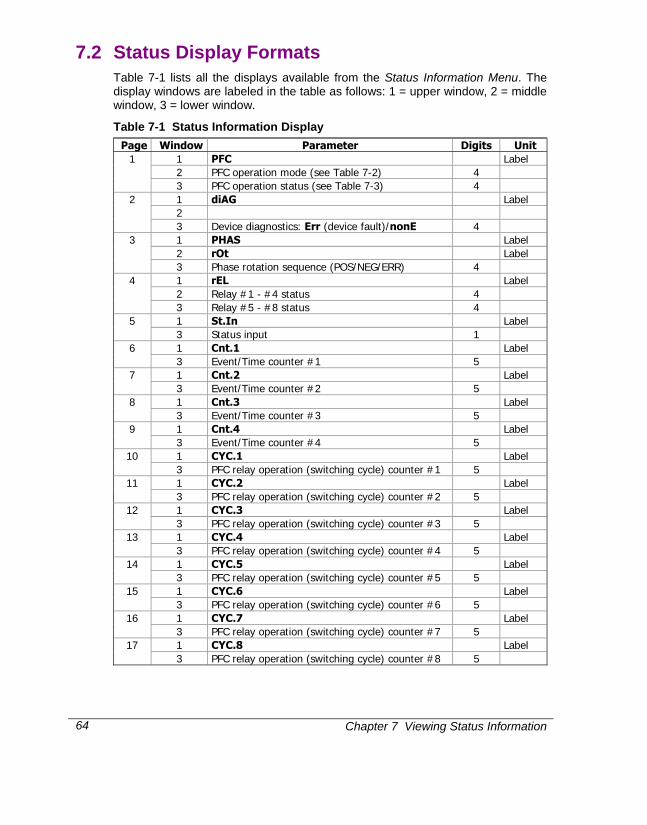
Chapter 7 Viewing Status Information
64
7.2 Status Display Formats Table 7-1 lists all the displays available from the Status Information Menu. The display windows are labeled in the table as follows: 1 = upper window, 2 = middle window, 3 = lower window.
Table 7-1 Status Information Display Page Window Parameter Digits Unit
1 PFC Label 2 PFC operation mode (see Table 7-2) 4
1
3 PFC operation status (see Table 7-3) 4 1 diAG Label 2
2
3 Device diagnostics: Err (device fault)/nonE 4 1 PHAS Label 2 rOt Label
3
3 Phase rotation sequence (POS/NEG/ERR) 4 1 rEL Label 2 Relay #1 - #4 status 4
4
3 Relay #5 - #8 status 4 1 St.In Label 5 3 Status input 1 1 Cnt.1 Label 6 3 Event/Time counter #1 5 1 Cnt.2 Label 7 3 Event/Time counter #2 5 1 Cnt.3 Label 8 3 Event/Time counter #3 5 1 Cnt.4 Label 9 3 Event/Time counter #4 5 1 CYC.1 Label 10 3 PFC relay operation (switching cycle) counter #1 5 1 CYC.2 Label 11 3 PFC relay operation (switching cycle) counter #2 5 1 CYC.3 Label 12 3 PFC relay operation (switching cycle) counter #3 5 1 CYC.4 Label 13 3 PFC relay operation (switching cycle) counter #4 5 1 CYC.5 Label 14 3 PFC relay operation (switching cycle) counter #5 5 1 CYC.6 Label 15 3 PFC relay operation (switching cycle) counter #6 5 1 CYC.7 Label 16 3 PFC relay operation (switching cycle) counter #7 5 1 CYC.8 Label 17 3 PFC relay operation (switching cycle) counter #8 5

Chapter 7 Viewing Status Information 65
Table 7-2 PFC Operation Modes Code Operation Mode
OFF The PFC is switched OFF Sh.dn The PFC is shutting down Aut.1 Self-adapting automatic operation mode Aut.2 Optimizing automatic operation mode HAnd Manual operation mode
Table 7-3 PFC Operation Status Code Operation Status Description
ready Ready A switching program is complete ALAr Alarm Operations are stopped by an alarm setpoint busy Busy Waiting until a switching delay is expired Lo.rEA Low reactive power
(automatic mode) Insufficient reactive power to trigger PFC
Ind.L Excessive inductive load (automatic mode)
Non-compensated inductive load
CAP.L Excessive capacitive load (automatic mode)
Non-compensated capacitive load
FULL Full (manual mode) All capacitor banks are switched in IdLE Idle (manual mode) All capacitor banks are switched out OFF OFF The PFC is switched off

Appendix: Technical Specifications
66
Appendix: Technical Specifications 8. ions
Input and Output Ratings 690 V: (standard)
DIRECT INPUT (690V + 15% line-to-line voltage and 400V +15% line-to-neutral) Burden: <0.5 VA INPUT USING PT Burden: <0.15 VA
3 galvanically isolated voltage inputs
120 V: (optional)
INPUT USING PT (120V +20% line-to-line voltage) Burden: <0.1 VA
5 A: (standard)
Maximum 6A RMS Burden: <0.1 VA Overload withstand: 10A RMS continuous, 250A RMS for 1 second
3 galvanically isolated current inputs
1 A: (optional)
Maximum 1.2 A RMS Burden: <0.02 VA Overload withstand: 2A RMS continuous, 50A RMS for 1 second
Voltage and current input terminals
UL recognized Screws: Brass, M4 Maximum wire section: 2.5 mm2 (12 AWG)
Optically isolated communication port
EIA RS-485 or RS-232 standard (factory set) RS-232: point-to-point, up to 15 meters RS-485: multidrop, up to 32 loads, up to 1200 meters
(4000 ft.) Maximum wire section: 1.5 mm2 (14 AWG)
Relay outputs 5 relays rated at 5A, 250 V AC / 5A, 30 V DC / 0.5A, 110 V DC 2 contacts (SPST Form A) 1 relay rated at 5A, 250 V AC / 5A, 30 V DC / 0.5A, 110 V DC 3 contacts (SPDT Form C) 2 relays rated at 3A, 250 V AC / 3A, 30 V DC / 0.5A, 110 V DC 2 contacts (SPST Form A) Maximum wire section: 1.5 mm2 (16 AWG)
Analog output (optional) 4-20 mA 0-20 mA
Accuracy 0.5%, Non-linearity 0.2% Load up to 510 Ohm 24V DC external power supply required
Status input Dry contact for external synchronization or monitoring Maximum impedance on: 300 ohm
Display 3 windows, high-brightness seven-segment digit LEDs Color relay status LED
Galvanically isolated power supply (factory set) 120&230V AC / 120&220 V DC 12 V DC 24 V DC 48 V DC
85-265V AC 50/60 Hz and 88-290V DC 10 W 9.6 - 19 V DC 19 - 37 V DC 37 - 72 V DC
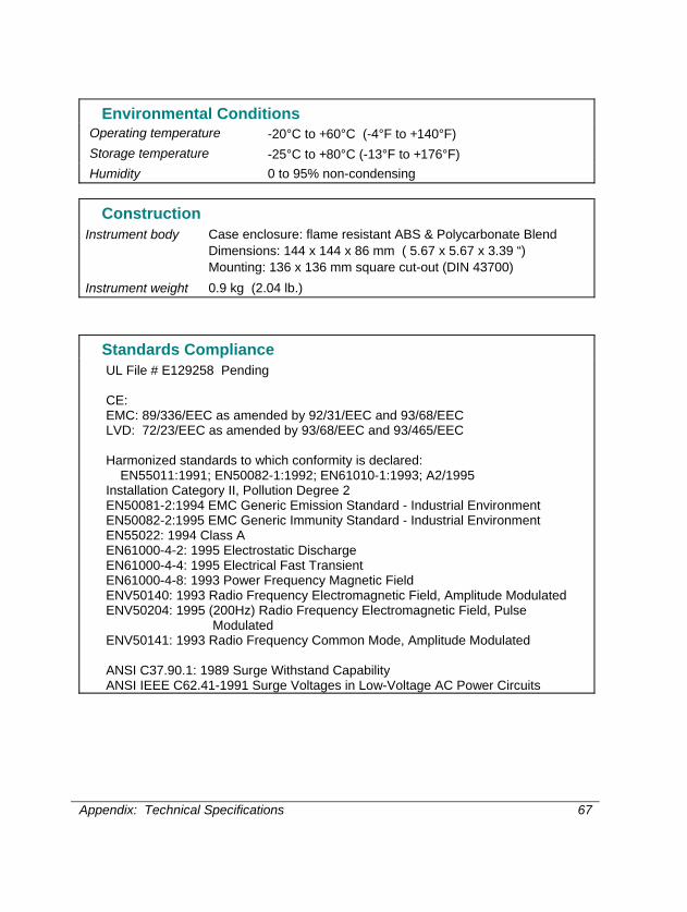
Appendix: Technical Specifications 67
Environmental Conditions Operating temperature -20°C to +60°C (-4°F to +140°F) Storage temperature -25°C to +80°C (-13°F to +176°F) Humidity 0 to 95% non-condensing
Construction Instrument body Case enclosure: flame resistant ABS & Polycarbonate Blend
Dimensions: 144 x 144 x 86 mm ( 5.67 x 5.67 x 3.39 “) Mounting: 136 x 136 mm square cut-out (DIN 43700)
Instrument weight 0.9 kg (2.04 lb.)
Standards Compliance UL File # E129258 Pending
CE: EMC: 89/336/EEC as amended by 92/31/EEC and 93/68/EEC LVD: 72/23/EEC as amended by 93/68/EEC and 93/465/EEC Harmonized standards to which conformity is declared:
EN55011:1991; EN50082-1:1992; EN61010-1:1993; A2/1995 Installation Category II, Pollution Degree 2 EN50081-2:1994 EMC Generic Emission Standard - Industrial Environment EN50082-2:1995 EMC Generic Immunity Standard - Industrial Environment EN55022: 1994 Class A EN61000-4-2: 1995 Electrostatic Discharge EN61000-4-4: 1995 Electrical Fast Transient EN61000-4-8: 1993 Power Frequency Magnetic Field ENV50140: 1993 Radio Frequency Electromagnetic Field, Amplitude Modulated ENV50204: 1995 (200Hz) Radio Frequency Electromagnetic Field, Pulse
Modulated ENV50141: 1993 Radio Frequency Common Mode, Amplitude Modulated ANSI C37.90.1: 1989 Surge Withstand Capability ANSI IEEE C62.41-1991 Surge Voltages in Low-Voltage AC Power Circuits

Appendix: Technical Specifications
68
Measurement Specifications Accuracy, % Range Display resolution (%Rdg) Parameter Full scale Rdg FS Conditions @ range Voltage 120V×PT
@ 120V
400V×PT @ 690V
208V×PT @ 120V
690V×PT @ 690V
0.25 10% to 120% FS 0 to 999,000 V Direct wiring (PT=1): 0.1 V @ 0.1V to 999.9 V Wiring via PTs (PT>1): 0.001 kV @ 0.001kV to 9.999 kV ≤0.1% @ 10.00 kV to 999.0 kV
Starting voltage 1.5% FS
Line current CT PRIMARY CURRENT 0.25 2% to 120% FS 0 to 9999 A 0.01 A @ 0.01A to 99.99 A ≤0.1% @ 100.0 A to 9999 A
Starting current 0.5% FS Active power 0.36×PT×CT @ 120V input
1.2×PT×CT @ 690V input
0.5 |PF| ≥ 0.5 -2,000,000 to +2,000,000 kW
Direct wiring (PT=1): 0.001 kW @ 0.001kW to 9.999 kW Wiring via PTs (PT>1): 0.001 MW @ 0.001MW to 9.999 MW ≤0.1% @ 10.00 MW to 2000 MW
Reactive power 0.36×PT×CT @ 120V input 1.2×PT×CT @ 690V input
0.5
|PF| ≤ 0.9 -2,000,000 to +2,000,000 kvar
Direct wiring (PT=1): 0.001 kvar @ 0.001kvar to 9.999 kvar Wiring via PTs (PT>1): 0.001 Mvar @ 0.001Mvar to 9.999 Mvar ≤0.1% @ 10.00 Mvar to 2000 Mvar
Apparent power 0.36×PT×CT @ 120V input 1.2×PT×CT @ 690V input
0.5 |PF| ≥ 0.5 0 to 2,000,000 kVA
Direct wiring (PT=1): 0.001 kVA @ 0.001kVA to 9.999 kVA Wiring via PTs (PT>1): 0.001 MVA @ 0.001MVA to 9.999 MVA ≤0.1% @ 10.00 MVA to 2000 MVA
Power factor 1 1 |PF| ≥ 0.5, I ≥ 10% FSI
-0.999 to +1.000 0.001
Frequency 0.02 45.00 to 65.00 Hz 0.01 Hz
or
orFor Ln reading and for 3OP2/3OP3 wiring modes
For LL readingexcept 3OP2/3OP3 wiring modes

Appendix: Technical Specifications 69
Accuracy, % Range Display resolution (%Rdg) Parameter Full scale Rdg FS Conditions @ range Neutral (unbalanced) current
CT PRIMARY CURRENT 0.5 2% to 120% FS 0 to 9999 A 0.01 A @ 0.01A to 99.99 A ≤0.1% @ 100.0 A to 9999 A
Starting current 0.5% FS Ampere demand same as for current KW demand (block & sliding) same as for kW KVA demand (block & sliding ) same as for kVA Total Harmonic Distortion THD U (I), % U1 (I1)
999.9 1.5 0.2 ≥ 0.1% FS, U (I) ≥ 10% FSU
(FSI)
0 to 999.9 0.1
Total Demand Distortion TDD (I), %
100 1.5 ≥ 1% FSI, I ≥ 10% FSI
0 to 100 0.1
Active energy Import & Export
same as for power 0 to 99,999 MWh 1 kWh @ 1 to 99,999 kWh 10 kWh @ 100 to 999.99 MWh 100 kWh @ 1,000 to 9,999.9 MWh 1MWh @ 10,000 to 99,999 MWh
Reactive energy Import & Export
same as for power 0 to 99,999 Mvarh 1 kvarh @ 1 to 99,999 kvarh 10 kvarh @ 100 to 999.99 Mvarh 100 kvarh @ 1,000 to 9,999.9 Mvarh 1Mvarh @ 10,000 to 99,999 Mvarh
Apparent energy same as for power 0 to 99,999 MVAh 1 kVAh @ 1 to 99,999 kVAh 10 kVAh @ 100 to 999.99 MVAh 100 kVAh @ 1,000 to 9,999.9 MVAh 1MVAh @ 10,000 to 99,999 MVAh
PT = external potential transformer ratio CT, CT Primary Current = primary current rating of external current transformer FSU = voltage full scale FSI = current full scale U1 = voltage fundamental I1 = current fundamental
@ 10% to 120% of voltage FS and 2% to 120% of current FS Higher resolution is achievable via communications Where the current is > 10% FS, the energy accuracy is better than 1.5% Rdg.
Additional Notes 1. Accuracy is expressed as ± (percentage of reading + percentage of full scale) ± 1 digit. This does not include inaccuracies introduced
by the user's potential and current transformers. 2. Specifications assume: voltage and current wave forms with THD ≤ 5% for kvar, kVA and PF; reference operating temperature: 20 - 26°C. 3. Ordinary measurement error is considerably less than the specified accuracy which indicates maximum error.

Index
70
Index A
accuracy, 70 active energy, 4, 70 active power, 3, 4, 35, 69 alarms, 14 ampere demand, 21, 30, 60 analog output, 2, 5, 8, 15, 24, 25 analog outputs, 22
B basic setup, 20, 39 burden, 67
C communications, 70 controller, 55 CT, 2, 21, 22, 25, 33, 69, 70 CT PRIMARY CURRENT, 22, 69, 70 current inputs, 8, 67 current transformers, 70
D demand, 3, 4, 15, 21, 23, 25, 30, 37, 38, 58,
60, 70 demand period, 15, 21, 38 display, 1, 2, 32, 33, 34, 38, 45, 56, 57, 58,
62, 64, 65 display mode, 33, 38, 57, 58, 64
E energy, 1, 2, 3, 4, 14, 26, 27, 35, 58, 62, 70 external synchronization, 3, 15, 21, 23, 67
F frequency, 1, 3, 4, 21, 29, 30, 60, 69
I inputs, 23, 67
L Load bar graph, 56
M measurement, 70 menu, 18, 20, 22, 23, 24, 26, 27, 28, 32, 33,
34, 36, 37, 38, 39, 43, 62, 64 Modbus, ii, 17, 21, 22
mounting, 1, 7
O open delta, 10, 21, 39, 40 options, 15 overload withstand, 67
P panel cut-out, 7 password, 2, 18, 36, 37, 57, 64 PComTest, 20 power, i, 2, 3, 4, 8, 15, 21, 22, 23, 24, 32, 34,
35, 37, 38, 50, 51, 55, 57, 58, 59, 60, 62, 63, 67, 69, 70
power demand, 3, 4, 15, 21, 23, 37, 38 power factor, 1, 50, 55, 69 power source, i, 8 power supply, 67 PT, 8, 21, 22, 25, 26, 62, 67, 69, 70 PT RATIO, 22 pulsing, 2, 14, 26, 27, 28, 32, 33, 38
R reactive energy, 4, 70 reactive power, 3, 4, 34, 35, 55, 69 relays, 2, 14, 26, 32, 67 reset, 21, 35, 37, 57, 58, 62, 64
S self tests, 62 setpoints, 22, 27, 28, 31, 32, 57 setup menus, 18, 20 setup mode, 18 sliding demand, 4 standards, 67, 68 status, 1, 3, 15, 18, 23, 31, 36, 55, 64, 65
T technical specifications, 67 terminals, ii, 8, 67
V voltage inputs, 67
W wiring configuration, 5, 8, 10 Wye, 10, 21, 39