C12 i - C12 i HT C18 i - C18 i HT PUMPS...NT 1001-D00 11.11 C12 i - C18 i - C12 i HT - C18 i HT e...
26
INSTALLATION OPERATION MAINTENANCE C12 i - C12 i HT C18 i - C18 i HT PUMPS INSTRUCTIONS 1001-D00 e Section 1001 Effective November 2011 Replaces August 2011 Original instructions Your distributor : Z.I. La Plaine des Isles - F 89000 AUXERRE - FRANCE Tel. : +33 (0)3.86.49.86.30 - Fax : +33 (0)3.86.49.87.17 [email protected] - www.mouvex.com
Transcript of C12 i - C12 i HT C18 i - C18 i HT PUMPS...NT 1001-D00 11.11 C12 i - C18 i - C12 i HT - C18 i HT e...
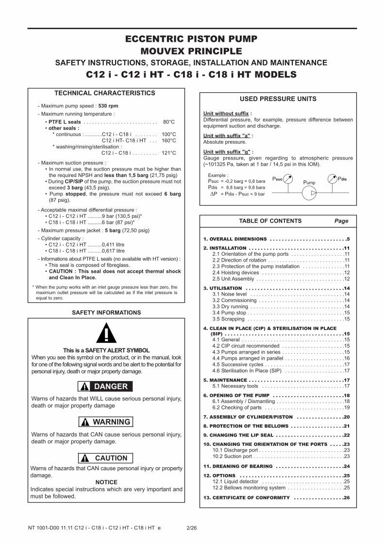
INSTALLATION
OPERATION
MAINTENANCE
C12 i - C12 i HTC18 i - C18 i HT
PUMPS
INSTRUCTIONS 1001-D00 e
Section 1001
Effective November 2011
Replaces August 2011
Original instructions
Your distributor :
Z.I. La Plaine des Isles - F 89000 AUXERRE - FRANCE
Tel. : +33 (0)3.86.49.86.30 - Fax : +33 (0)3.86.49.87.17
[email protected] - www.mouvex.com
2/26NT 1001-D00 11.11 C12 i - C18 i - C12 i HT - C18 i HT e
ECCENTRIC PISTON PUMPMOUVEX PRINCIPLE
SAFETY INSTRUCTIONS, STORAGE, INSTALLATION AND MAINTENANCE
C12 i - C12 i HT - C18 i - C18 i HT MODELS
TECHNICAL CHARACTERISTICS
- Maximum pump speed : 530 rpm
- Maximum running temperature :
• PTFE L seals . . . . . . . . . . . . . . . . . . . . . . . . . . 80°C
• other seals :
* continuous : ............C12 i - C18 i . . . . . . . . 100°C
C12 i HT- C18 i HT . . . 160°C
* washing/rinsing/sterilisation :
C12 i - C18 i . . . . . . . . . 121°C
- Maximum suction pressure :
• In normal use, the suction pressure must be higher than
the required NPSH and less than 1,5 barg (21,75 psig)
• During CIP/SIP of the pump, the suction pressure must not
exceed 3 barg (43,5 psig).
• Pump stopped, the pressure must not exceed 6 barg
(87 psig).
- Acceptable maximal differential pressure :
• C12 i - C12 i HT ..........9 bar (130,5 psi)*
• C18 i - C18 i HT ..........6 bar (87 psi)*
- Maximum pressure jacket : 5 barg (72,50 psig)
- Cylinder capacity :
• C12 i - C12 i HT ..........0,411 litre
• C18 i - C18 i HT ..........0,617 litre
- Informations about PTFE L seals (no available with HT version) :
• This seal is composed of fibreglass.
• CAUTION : This seal does not accept thermal shock
and Clean In Place.
* When the pump works with an inlet gauge pressure less than zero, the
maximum outlet pressure will be calculated as if the inlet pressure is
equal to zero.
1. OVERALL DIMENSIONS . . . . . . . . . . . . . . . . . . . . . . . . . .5
2. INSTALLATION . . . . . . . . . . . . . . . . . . . . . . . . . . . . . . . .112.1 Orientation of the pump ports . . . . . . . . . . . . . . . . . . .11
2.2 Direction of rotation . . . . . . . . . . . . . . . . . . . . . . . . . . .11
2.3 Protection of the pump installation . . . . . . . . . . . . . . .11
2.4 Hoisting devices . . . . . . . . . . . . . . . . . . . . . . . . . . . . .12
2.5 Unit Assembly . . . . . . . . . . . . . . . . . . . . . . . . . . . . . . .12
3. UTILISATION . . . . . . . . . . . . . . . . . . . . . . . . . . . . . . . . .143.1 Noise level . . . . . . . . . . . . . . . . . . . . . . . . . . . . . . . . .14
3.2 Commissioning . . . . . . . . . . . . . . . . . . . . . . . . . . . . . .14
3.3 Dry running . . . . . . . . . . . . . . . . . . . . . . . . . . . . . . . . .14
3.4 Pump stop . . . . . . . . . . . . . . . . . . . . . . . . . . . . . . . . . .15
3.5 Scrapping . . . . . . . . . . . . . . . . . . . . . . . . . . . . . . . . . .15
4. CLEAN IN PLACE (CIP) & STERILISATION IN PLACE (SIP) . . . . . . . . . . . . . . . . . . . . . . . . . . . . . . . . . . . . . . . .154.1 General . . . . . . . . . . . . . . . . . . . . . . . . . . . . . . . . . . . .15
4.2 CIP circuit recommended . . . . . . . . . . . . . . . . . . . . . .15
4.3 Pumps arranged in series . . . . . . . . . . . . . . . . . . . . . .15
4.4 Pumps arranged in parallel . . . . . . . . . . . . . . . . . . . . .16
4.5 Successive cycles . . . . . . . . . . . . . . . . . . . . . . . . . . . .17
4.6 Sterilisation In Place (SIP) . . . . . . . . . . . . . . . . . . . . .17
5. MAINTENANCE . . . . . . . . . . . . . . . . . . . . . . . . . . . . . . . .175.1 Necessary tools . . . . . . . . . . . . . . . . . . . . . . . . . . . . .17
6. OPENING OF THE PUMP . . . . . . . . . . . . . . . . . . . . . . . .186.1 Assembly / Dismantling . . . . . . . . . . . . . . . . . . . . . . . .18
6.2 Checking of parts . . . . . . . . . . . . . . . . . . . . . . . . . . . .19
7. ASSEMBLY OF CYLINDER/PISTON . . . . . . . . . . . . . . . .20
8. PROTECTION OF THE BELLOWS . . . . . . . . . . . . . . . . . .21
9. CHANGING THE LIP SEAL . . . . . . . . . . . . . . . . . . . . . . .22
10. CHANGING THE ORIENTATION OF THE PORTS . . . . .2310.1 Discharge port . . . . . . . . . . . . . . . . . . . . . . . . . . . . . .23
10.2 Suction port . . . . . . . . . . . . . . . . . . . . . . . . . . . . . . . .23
11. DREANING OF BEARING . . . . . . . . . . . . . . . . . . . . . . .24
12. OPTIONS . . . . . . . . . . . . . . . . . . . . . . . . . . . . . . . . . . .2512.1 Liquid detector . . . . . . . . . . . . . . . . . . . . . . . . . . . . .25
12.2 Bellows monitoring system . . . . . . . . . . . . . . . . . . . .25
13. CERTIFICATE OF CONFORMITY . . . . . . . . . . . . . . . . .26
TABLE OF CONTENTS Page
This is a SAFETY ALERT SYMBOL
When you see this symbol on the product, or in the manual, look
for one of the following signal words and be alert to the potential for
personal injury, death or major property damage.
Warns of hazards that WILL cause serious personal injury,
death or major property damage
Warns of hazards that CAN cause serious personal injury,
death or major property damage.
Warns of hazards that CAN cause personal injury or property
damage.
NOTICE
Indicates special instructions which are very important and
must be followed.
SAFETY INFORMATIONS
WARNING
CAUTION
DANGER
USED PRESSURE UNITS
Unit without suffix :
Differential pressure, for example, pressure difference between
equipment suction and discharge.
Unit with suffix "a" :
Absolute pressure.
Unit with suffix "g" :
Gauge pressure, given regarding to atmospheric pressure
(~101325 Pa, taken at 1 bar / 14,5 psi in this IOM).
Pompe
Pasp Pref
Psuc PdisPump
Example :
Psuc = -0,2 barg = 0,8 bara
Pdis = 8,8 barg = 9,8 bara
∆P = Pdis - Psuc = 9 bar
3/26NT 1001-D00 11.11 C12 i - C18 i - C12 i HT - C18 i HT e
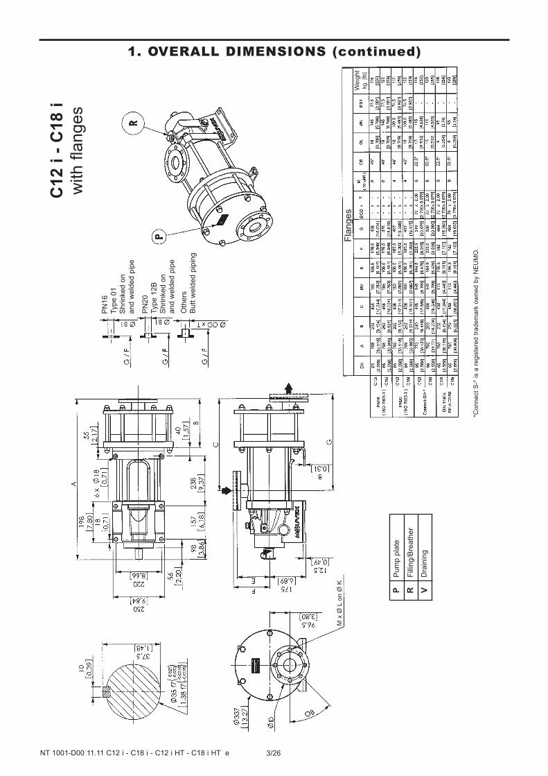
1. OVERALL DIMENSIONS (continued)C
12 i
- C
18 i
with f
langes
*Connect
S-®
is a
regis
tere
d t
radem
ark
ow
ne
d b
y N
EU
MO
.
Fla
nges
We
igh
tkg
[lb]
M x
Ø L
on Ø
K
PN
16
Typ
e 0
1
Shrinked o
n
and
weld
ed p
ipe
PN
20
Type 1
2B
Shrinked o
n
and w
eld
ed p
ipe
Oth
ers
Butt w
eld
ed p
ipin
g
Pum
p p
late
Fill
ing/B
reath
er
Dra
inin
g
P R V
4/26NT 1001-D00 11.11 C12 i - C18 i - C12 i HT - C18 i HT e
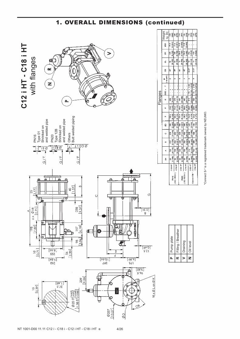
1. OVERALL DIMENSIONS (continued)
*Connect
S-®
is a
regis
tere
d t
radem
ark
ow
ne
d b
y N
EU
MO
.
PN
16
Type 0
1
Shrinked o
n
and w
eld
ed p
ipe
PN
20
Type 1
2B
Shrinke
d o
n
and w
eld
ed p
ipe
Oth
ers
Butt w
eld
ed p
ipin
g
C12 i
HT
- C
18 i
HT
with f
langes
Fla
nges
We
igh
tkg
[lb]
M x
Ø L
on Ø
K
Pum
p p
late
Fill
ing /
Bre
ath
er
Dra
inin
g
Oil
level
P R V N
5/26NT 1001-D00 11.11 C12 i - C18 i - C12 i HT - C18 i HT e
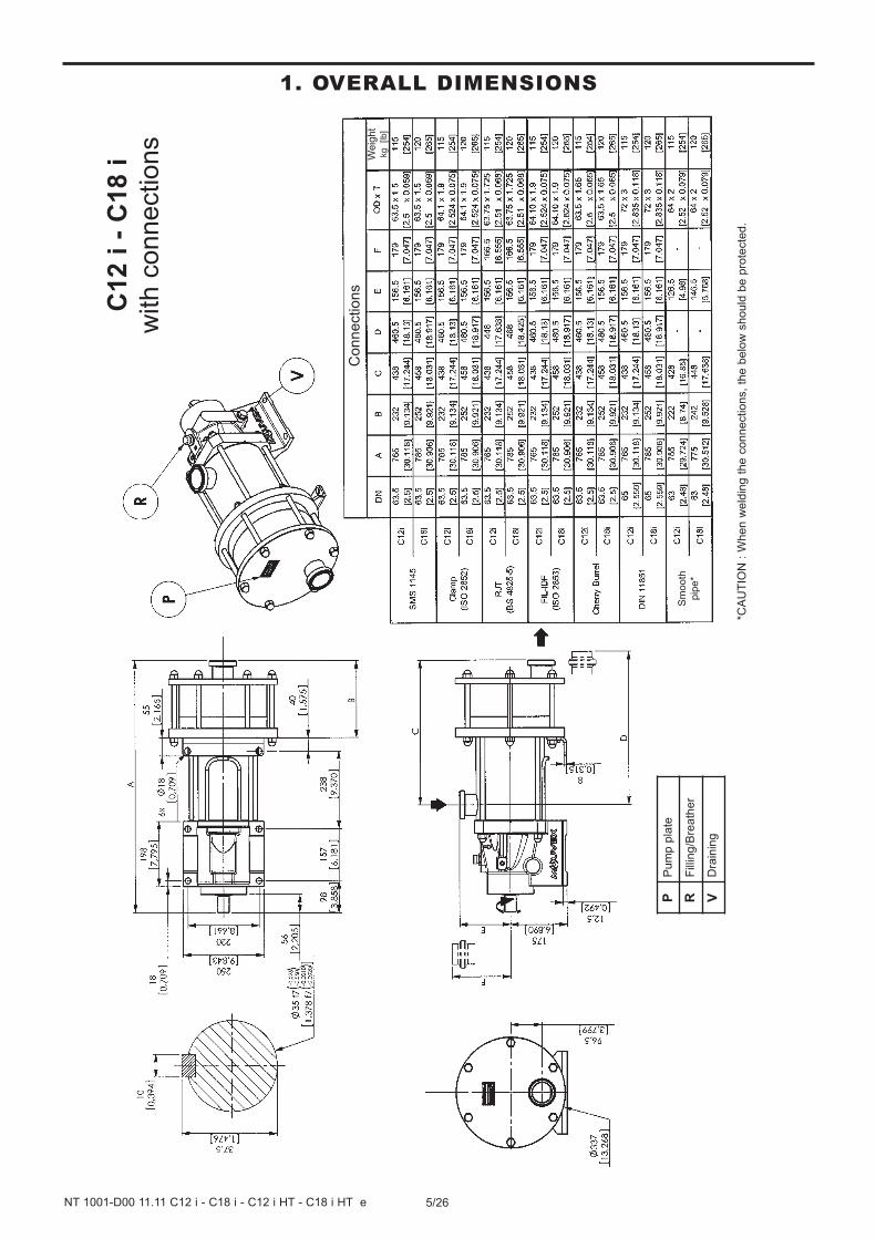
1. OVERALL DIMENSIONSC
12 i
- C
18 i
with c
onnections
Connections
*CA
UT
ION
: W
hen w
eld
ing t
he c
onnections,
the b
elo
w s
hould
be p
rote
cte
d.
We
igh
tkg
[lb]
Sm
ooth
pip
e*
Pum
p p
late
Fill
ing/B
reath
er
Dra
inin
g
P R V
6/26NT 1001-D00 11.11 C12 i - C18 i - C12 i HT - C18 i HT e
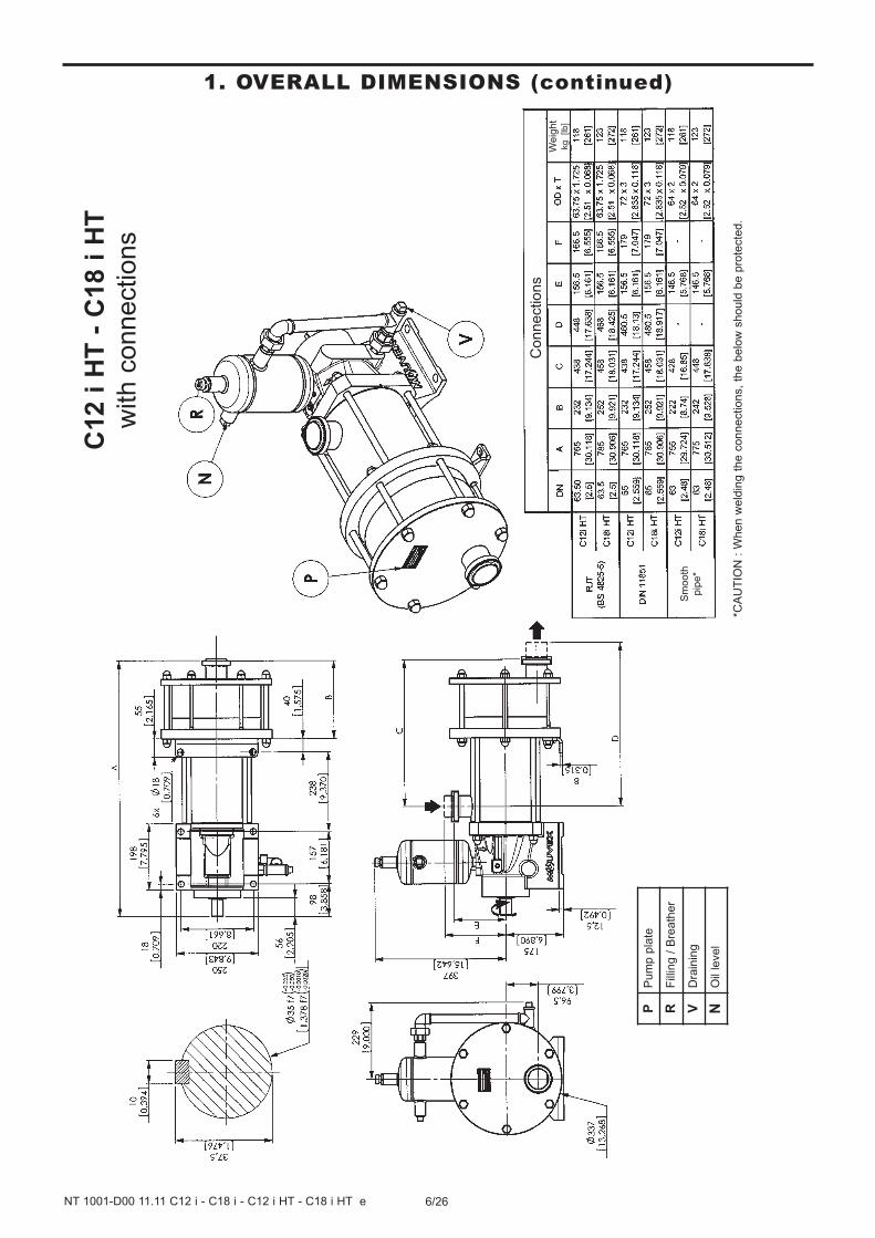
1. OVERALL DIMENSIONS (continued)C
12 i
HT
- C
18 i
HT
with c
onnections
Connections
*CA
UT
ION
: W
hen w
eld
ing t
he c
onnections,
the b
elo
w s
hould
be p
rote
cte
d.
Sm
ooth
pip
e*
We
igh
tkg
[lb]
Pum
p p
late
Fill
ing /
Bre
ath
er
Dra
inin
g
Oil
level
P R V N
7/26NT 1001-D00 11.11 C12 i - C18 i - C12 i HT - C18 i HT e
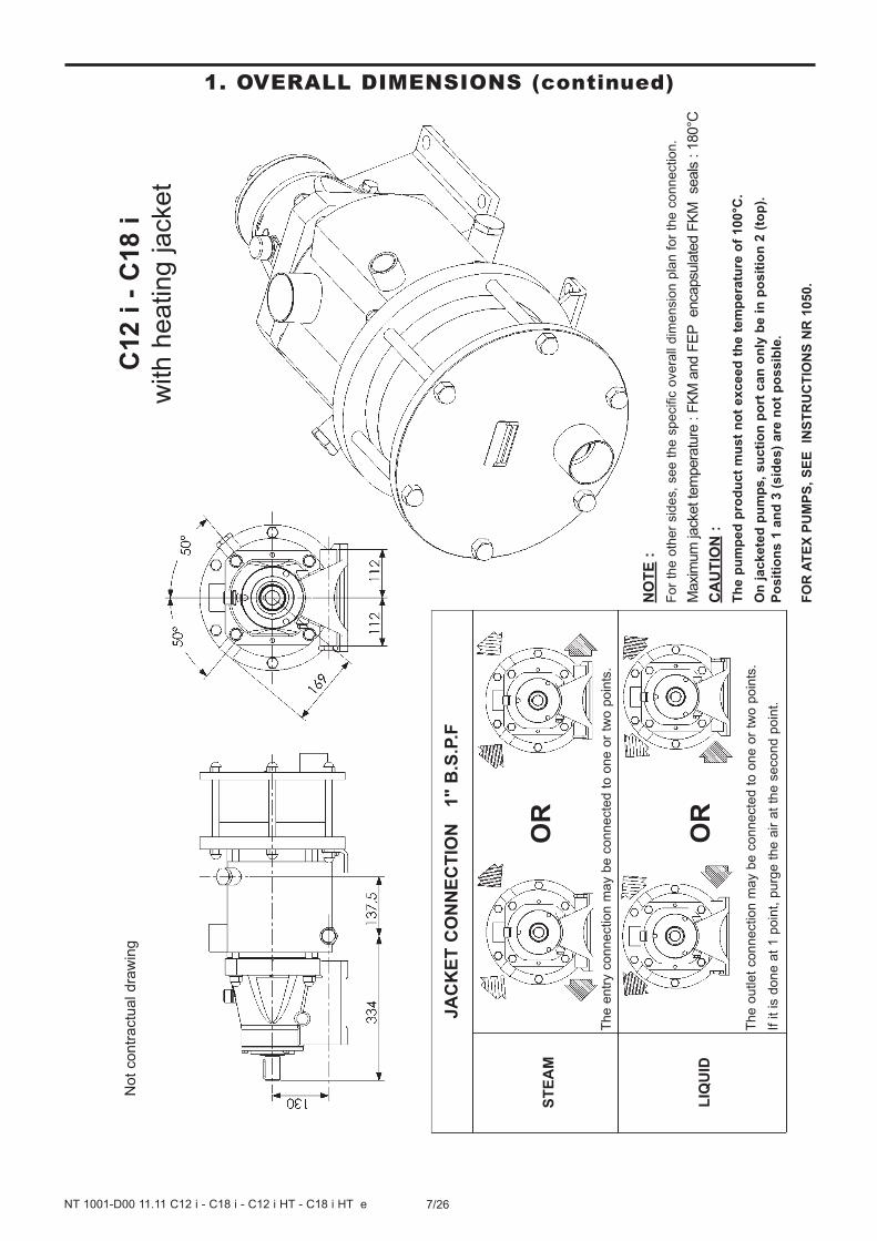
1. OVERALL DIMENSIONS (continued)
C12 i
- C
18 i
with h
eating jacket
NO
TE
:
For
the o
ther
sid
es,
se
e t
he
sp
ecific
ove
rall
dim
en
sio
n p
lan
fo
r th
e c
on
ne
ctio
n.
Maxi
mum
jack
et te
mpera
ture
: F
KM
and F
EP
enca
psu
late
d F
KM
se
als
: 1
80°C
CA
UT
ION
:
Th
e p
um
ped
pro
du
ct
mu
st
no
t e
xc
ee
d t
he
te
mp
era
ture
of
10
0°C
.
On
jackete
d p
um
ps,
su
cti
on
po
rt c
an
on
ly b
e i
n p
os
itio
n 2
(to
p).
Po
sit
ion
s 1
an
d 3
(s
ide
s)
are
no
t p
os
sib
le.
FO
R A
TE
X P
UM
PS
, S
EE
IN
ST
RU
CT
ION
S N
R 1
05
0.
JA
CK
ET
CO
NN
EC
TIO
N
1" B
.S.P
.F
The e
ntr
y c
onnection m
ay b
e c
onnecte
d t
o o
ne o
r tw
o p
oin
ts.
ST
EA
M
LIQ
UID
The o
utlet
connection m
ay b
e c
onnecte
d t
o o
ne o
r tw
o p
oin
ts.
If it
is d
one a
t 1 p
oin
t, p
urg
e t
he a
ir a
t th
e s
econd p
oin
t.
OR
OR
Not
contr
actu
al dra
win
g
8/26NT 1001-D00 11.11 C12 i - C18 i - C12 i HT - C18 i HT e
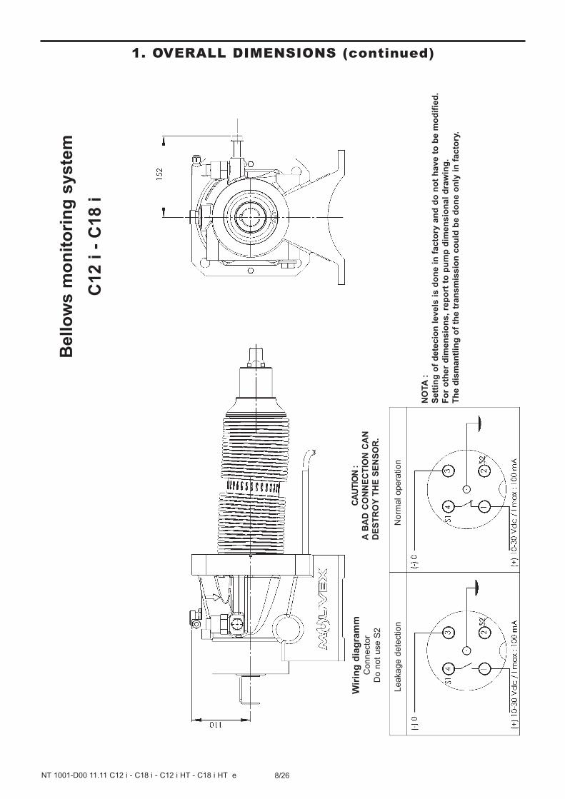
1. OVERALL DIMENSIONS (continued)B
ello
ws m
on
ito
rin
g s
yste
m
C12 i
- C
18 i
Leakage d
ete
ction
NO
TA
:
Sett
ing
of
dete
cio
n l
eve
ls i
s d
on
e i
n f
ac
tory
an
d d
o n
ot
ha
ve
to
be
mo
dif
ied
.
Fo
r o
ther
dim
en
sio
ns,
rep
ort
to
pu
mp
dim
en
sio
na
l d
raw
ing
.
Th
e d
ism
an
tlin
g o
f th
e t
ran
sm
iss
ion
co
uld
be
do
ne
on
ly i
n f
ac
tory
.
Wir
ing
dia
gra
mm
Connecto
r
Do n
ot
use S
2
Norm
al opera
tion
CA
UTIO
N :
A B
AD
CO
NN
EC
TIO
N C
AN
DE
ST
RO
Y T
HE
SE
NS
OR
.
9/26NT 1001-D00 11.11 C12 i - C18 i - C12 i HT - C18 i HT e
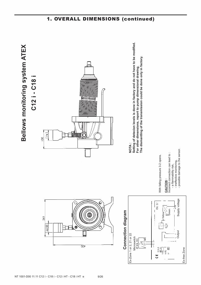
1. OVERALL DIMENSIONS (continued)B
ello
ws m
on
ito
rin
g s
yste
m A
TE
X
C12 i
- C
18 i
NO
TA
:
Sett
ing
of
dete
cio
n l
evels
is d
on
e i
n f
ac
tory
an
d d
o n
ot
ha
ve
to
be
mo
dif
ied
.
Fo
r o
ther
dim
en
sio
ns,
rep
ort
to
pu
mp
dim
en
sio
na
l d
raw
ing
.
Th
e d
ism
an
tlin
g o
f th
e t
ran
sm
iss
ion
co
uld
be
do
ne
on
ly i
n f
ac
tory
.
With f
alli
ng p
ressure
3-2
opens.
CA
UT
ION
:
Incorr
ect
connection c
an lead t
o :
- a f
lam
mabili
ty r
isk,
- in
effective m
onitoring,
- possib
le d
am
age t
o t
he s
ensor.
Co
nn
ecti
on
dia
gra
m
Ex-f
ree Z
one
Ex-Z
one 1
or
2,
21 o
r 22
Supply
voltage
Outp
ut
Yello
w
Gre
en
Mic
rosw
itch

10/26NT 1001-D00 11.11 C12 i - C18 i - C12 i HT - C18 i HT e
1. OVERALL DIMENSIONS (continued)
NO
TA
:
Sett
ing
of
dete
cio
n l
evels
is
do
ne
in
fa
cto
ry a
nd
do
no
t h
av
e t
o b
e m
od
ifie
d.
Fo
r o
ther
dim
en
sio
ns,
rep
ort
to
pu
mp
dim
en
sio
na
l d
raw
ing
.
Th
e d
ism
an
tlin
g o
f th
e t
ran
sm
iss
ion
co
uld
be
do
ne
on
ly i
n f
ac
tory
.
Do
ub
le p
ly t
ran
sm
issio
n w
ith
man
om
ete
r
C12 i
- C
18 i
Gre
en z
one
Red z
one
Red z
one
11/26NT 1001-D00 11.11 C12 i - C18 i - C12 i HT - C18 i HT e
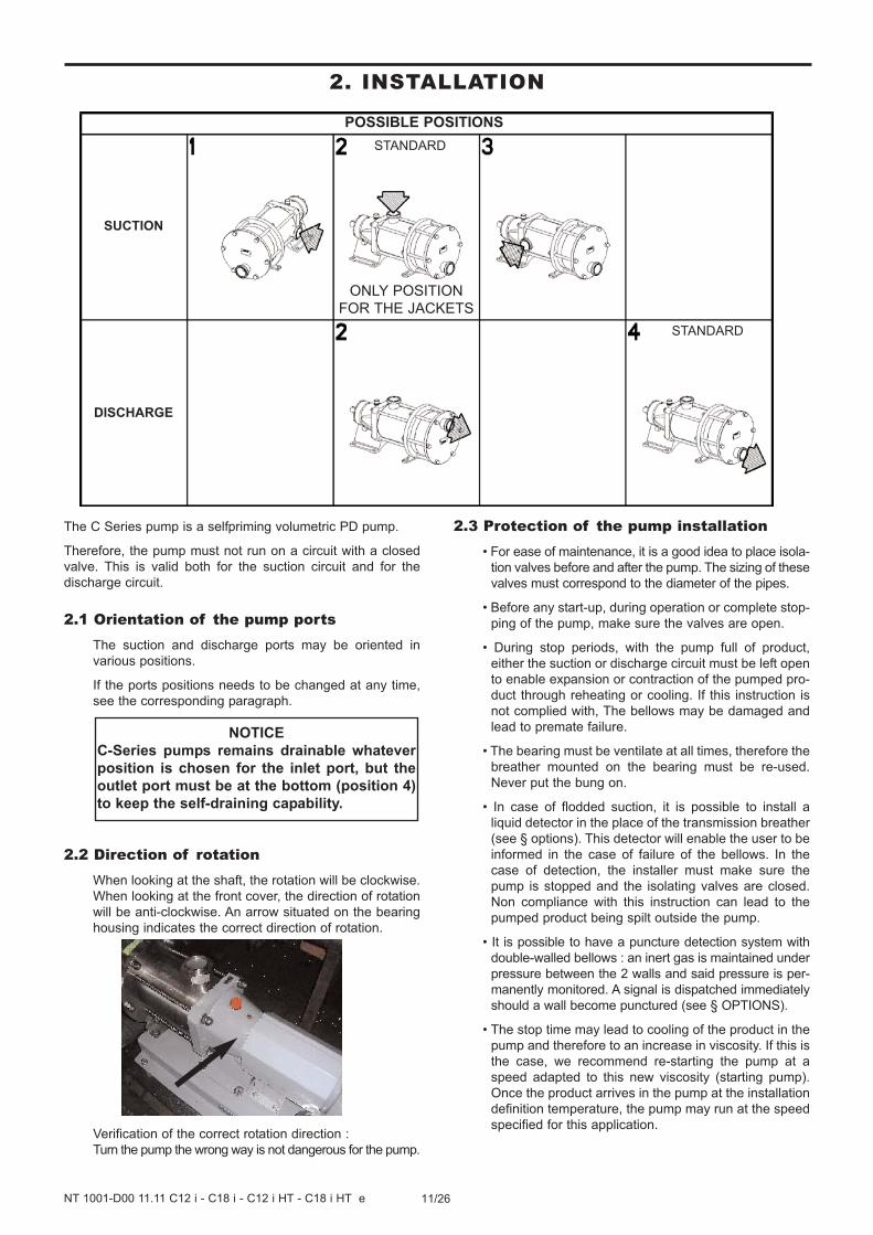
POSSIBLE POSITIONS
SUCTION
DISCHARGE
ONLY POSITION
FOR THE JACKETS
2. INSTALLATION
The C Series pump is a selfpriming volumetric PD pump.
Therefore, the pump must not run on a circuit with a closed
valve. This is valid both for the suction circuit and for the
discharge circuit.
2.1 Orientation of the pump portsThe suction and discharge ports may be oriented in
various positions.
If the ports positions needs to be changed at any time,
see the corresponding paragraph.
2.2 Direction of rotationWhen looking at the shaft, the rotation will be clockwise.
When looking at the front cover, the direction of rotation
will be anti-clockwise. An arrow situated on the bearing
housing indicates the correct direction of rotation.
Verification of the correct rotation direction :
Turn the pump the wrong way is not dangerous for the pump.
2.3 Protection of the pump installation• For ease of maintenance, it is a good idea to place isola-
tion valves before and after the pump. The sizing of these
valves must correspond to the diameter of the pipes.
• Before any start-up, during operation or complete stop-
ping of the pump, make sure the valves are open.
• During stop periods, with the pump full of product,
either the suction or discharge circuit must be left open
to enable expansion or contraction of the pumped pro-
duct through reheating or cooling. If this instruction is
not complied with, The bellows may be damaged and
lead to premate failure.
• The bearing must be ventilate at all times, therefore the
breather mounted on the bearing must be re-used.
Never put the bung on.
• In case of flodded suction, it is possible to install a
liquid detector in the place of the transmission breather
(see § options). This detector will enable the user to be
informed in the case of failure of the bellows. In the
case of detection, the installer must make sure the
pump is stopped and the isolating valves are closed.
Non compliance with this instruction can lead to the
pumped product being spilt outside the pump.
• It is possible to have a puncture detection system with
double-walled bellows : an inert gas is maintained under
pressure between the 2 walls and said pressure is per-
manently monitored. A signal is dispatched immediately
should a wall become punctured (see § OPTIONS).
• The stop time may lead to cooling of the product in the
pump and therefore to an increase in viscosity. If this is
the case, we recommend re-starting the pump at a
speed adapted to this new viscosity (starting pump).
Once the product arrives in the pump at the installation
definition temperature, the pump may run at the speed
specified for this application.
NOTICE
C-Series pumps remains drainable whatever
position is chosen for the inlet port, but the
outlet port must be at the bottom (position 4)
to keep the self-draining capability.
STANDARD
STANDARD
12/26NT 1001-D00 11.11 C12 i - C18 i - C12 i HT - C18 i HT e
• Protection against excess pressure :
The pump must be protected against excess pressure. It
can be delivered with a pressure switch to carry out this
function.
If protection is provided by a control valve, check that the
system does not generate excess pressure at the bel-
lows (particularly if there are water hammers). Operating
in this way would damage the bellows and shorten their
lifetime.
• Protection against foreign bodies :
The pump and the installation must also be protected
against any risk of damage through the passage of
foreign bodies by mounting a pre-filter at the pump suc-
tion.
In the case of foreseeable clogging of the pre-filter, we
recommend using a vacuum switch to inform the user
of pre-filter clogging. Prolonged running under cavita-
tion may damage the pump.
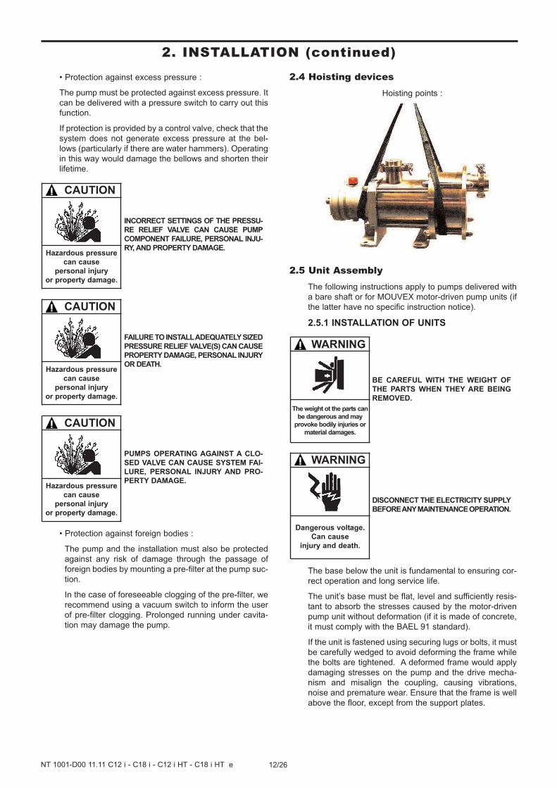
2.4 Hoisting devicesHoisting points :
2.5 Unit AssemblyThe following instructions apply to pumps delivered with
a bare shaft or for MOUVEX motor-driven pump units (if
the latter have no specific instruction notice).
2.5.1 INSTALLATION OF UNITS
The base below the unit is fundamental to ensuring cor-
rect operation and long service life.
The unit’s base must be flat, level and sufficiently resis-
tant to absorb the stresses caused by the motor-driven
pump unit without deformation (if it is made of concrete,
it must comply with the BAEL 91 standard).
If the unit is fastened using securing lugs or bolts, it must
be carefully wedged to avoid deforming the frame while
the bolts are tightened. A deformed frame would apply
damaging stresses on the pump and the drive mecha-
nism and misalign the coupling, causing vibrations,
noise and premature wear. Ensure that the frame is well
above the floor, except from the support plates.
DISCONNECT THE ELECTRICITY SUPPLY
BEFORE ANY MAINTENANCE OPERATION.
WARNING
Dangerous voltage.
Can cause
injury and death.
BE CAREFUL WITH THE WEIGHT OF
THE PARTS WHEN THEY ARE BEING
REMOVED.
WARNING
The weight ot the parts can
be dangerous and may
provoke bodily injuries or
material damages.
PUMPS OPERATING AGAINST A CLO-
SED VALVE CAN CAUSE SYSTEM FAI-
LURE, PERSONAL INJURY AND PRO-
PERTY DAMAGE.
CAUTION
Hazardous pressure
can cause
personal injury
or property damage.
FAILURE TO INSTALL ADEQUATELY SIZED
PRESSURE RELIEF VALVE(S) CAN CAUSE
PROPERTY DAMAGE, PERSONAL INJURY
OR DEATH.
CAUTION
Hazardous pressure
can cause
personal injury
or property damage.
INCORRECT SETTINGS OF THE PRESSU-
RE RELIEF VALVE CAN CAUSE PUMP
COMPONENT FAILURE, PERSONAL INJU-
RY, AND PROPERTY DAMAGE.
CAUTION
Hazardous pressure
can cause
personal injury
or property damage.
2. INSTALLATION (continued)
13/26NT 1001-D00 11.11 C12 i - C18 i - C12 i HT - C18 i HT e
If the unit is to be used in a food environment, support
plates that allow the unit to be lifted for easier cleaning
are recommended.
Allow, if possible, a clear space of approximately 50 cm
on each side of the motor-driven pump unit (overall
dimensions) to facilitate cleaning and give access if
necessary to the pump, reduction gear and motor faste-
ning nuts. In all cases, the dimensions around the motor-
driven pump unit must be designed to give the space
required for dismantling the pump (if the need arises,
use the values given on the overall dimension drawing).
For staff and equipment protection, the frame includes a
ground connection point that should be used.
2.5.2 ALIGNMENT OF THE MOTOR/PUMP OR
REDUCTION GEAR/PUMP SHAFTS
NEVER START A UNIT IF THE COUPLING ALIGN-
MENT IS INCORRECT. THIS IS A CONDITION OF OUR
GUARANTEE.
REMINDER :
Coupling must never be used to compensate for a misa-
lignment.
To control the alignment between the coupling and the
shaft, use a straight-edge for concentricity and thickness
gauges for angular misalignment (see instructions of the
coupling for authorised values).
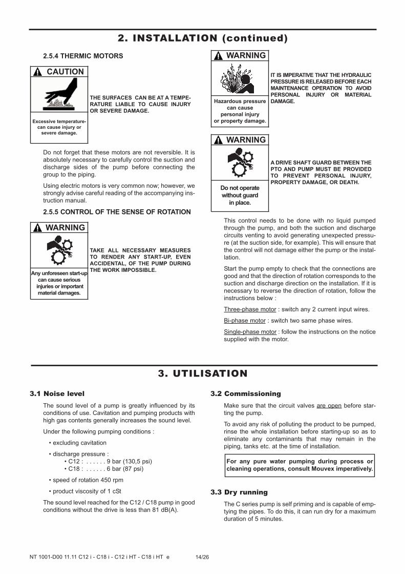
The 3 figures below show in detail the operation and the
possible defects :
Controlling the alignment at each stage of the installation
is important to be sure that none of these stages have
generated stresses on the unit or the pump :
• after fastening on the foundations.
• after fastening the pipes.
• after the pump has been operated at the normal
operating temperature.
Where the pumps are supplied assembled as a unit, the
motor and pump shafts have been perfectly aligned in
the factory before delivery, but they must be systemati-
cally controlled on acceptance at the site and realigned
if necessary.
To do this, do not modify the wedging of the various
parts, but check the flatness of the support surface and
use the adjustable foot to clear the frame of stresses that
could affect it.
2.5.3 ELECTIC MOTORS
Check the compatibility of the instructions on the motor
with the supply voltage.
Follow the wiring diagram, use wiring that is appropriate
for the power and be particularly careful about the
contacts which must be well tightened.
The motors should be protected with circuit breakers
and suitable fuses. Connect the regulatory electrical
grounding.
DISCONNECT THE ELECTRICITY SUPPLY
BEFORE ANY MAINTENANCE OPERATION.
WARNING
Dangerous voltage.
Can cause
injury and death.
Make this check for 4 points:up - down - left - right
Correct
Out-of-parallelism
Angular defect
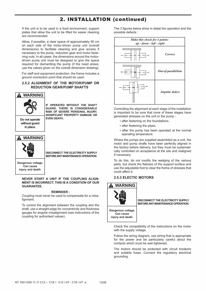
DISCONNECT THE ELECTRICITY SUPPLY
BEFORE ANY MAINTENANCE OPERATION.
WARNING
Dangerous voltage.
Can cause
injury and death.
IF OPERATED WITHOUT THE SHAFT
GUARD, THERE IS CONSIDERABLE
RISK OF SEVERE PERSONAL INJURY,
SIGNIFICANT PROPERTY DAMAGE OR
EVEN DEATH.
WARNING
Do not operate
without guard
in place.
2. INSTALLATION (continued)
14/26NT 1001-D00 11.11 C12 i - C18 i - C12 i HT - C18 i HT e
2.5.4 THERMIC MOTORS
Do not forget that these motors are not reversible. It is
absolutely necessary to carefully control the suction and
discharge sides of the pump before connecting the
group to the piping.
Using electric motors is very common now; however, we
strongly advise careful reading of the accompanying ins-
truction manual.
2.5.5 CONTROL OF THE SENSE OF ROTATION
This control needs to be done with no liquid pumped
through the pump, and both the suction and discharge
circuits venting to avoid generating unexpected pressu-
re (at the suction side, for example). This will ensure that
the control will not damage either the pump or the instal-
lation.
Start the pump empty to check that the connections are
good and that the direction of rotation corresponds to the
suction and discharge direction on the installation. If it is
necessary to reverse the direction of rotation, follow the
instructions below :
Three-phase motor : switch any 2 current input wires.
Bi-phase motor : switch two same phase wires.
Single-phase motor : follow the instructions on the notice
supplied with the motor.
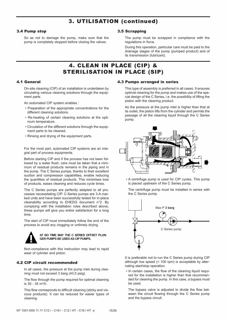
THE SURFACES CAN BE AT A TEMPE-
RATURE LIABLE TO CAUSE INJURY
OR SEVERE DAMAGE.
CAUTION
Excessive temperature-
can cause injury or
severe damage.
A DRIVE SHAFT GUARD BETWEEN THE
PTO AND PUMP MUST BE PROVIDED
TO PREVENT PERSONAL INJURY,
PROPERTY DAMAGE, OR DEATH.
WARNING
Do not operate
without guard
in place.
IT IS IMPERATIVE THAT THE HYDRAULIC
PRESSURE IS RELEASED BEFORE EACH
MAINTENANCE OPERATION TO AVOID
PERSONAL INJURY OR MATERIAL
DAMAGE.
WARNING
Hazardous pressure
can cause
personal injury
or property damage.
TAKE ALL NECESSARY MEASURES
TO RENDER ANY START-UP, EVEN
ACCIDENTAL, OF THE PUMP DURING
THE WORK IMPOSSIBLE.
WARNING
Any unforeseen start-up
can cause serious
injuries or important
material damages.
2. INSTALLATION (continued)
3.1 Noise levelThe sound level of a pump is greatly influenced by its
conditions of use. Cavitation and pumping products with
high gas contents generally increases the sound level.
Under the following pumping conditions :
• excluding cavitation
• discharge pressure :
• C12 : . . . . . . 9 bar (130,5 psi)
• C18 : . . . . . . 6 bar (87 psi)
• speed of rotation 450 rpm
• product viscosity of 1 cSt
The sound level reached for the C12 / C18 pump in good
conditions without the drive is less than 81 dB(A).
3.2 CommissioningMake sure that the circuit valves are open before star-
ting the pump.
To avoid any risk of polluting the product to be pumped,
rinse the whole installation before starting-up so as to
eliminate any contaminants that may remain in the
piping, tanks etc. at the time of installation.
3.3 Dry runningThe C series pump is self priming and is capable of emp-
tying the pipes. To do this, it can run dry for a maximum
duration of 5 minutes.
For any pure water pumping during process or
cleaning operations, consult Mouvex imperatively.
3. UTILISATION
15/26NT 1001-D00 11.11 C12 i - C18 i - C12 i HT - C18 i HT e
4. CLEAN IN PLACE (CIP) & STERILISATION IN PLACE (SIP)
4.1 GeneralOn-site cleaning (CIP) of an installation is undertaken by
circulating various cleaning solutions through the equip-
ment parts.
An automated CIP system enables :
• Preparation of the appropriate concentrations for the
different cleaning solutions.
• Re-heating of certain cleaning solutions at the opti-
mum temperature.
• Circulation of the different solutions through the equip-
ment parts to be cleaned.
• Rinsing and drying of the equipment parts.
For the most part, automated CIP systems are an inte-
gral part of process equipments.
Before starting CIP and if the process has not been fol-
lowed by a water flush, care must be taken that a mini-
mum of residual products remains in the piping and in
the pump. The C Series pumps, thanks to their excellent
suction and compression capabilities, enable reducing
the quantities of residual products. This minimises loss
of products, eases cleaning and reduces cycle times.
The C Series pumps are perfectly adapted to all pro-
cesses necessitating CIP. C-Series pumps are 3-A mar-
ked units and have been successfully tested for in-place
cleanability according to EHEDG document n°2. By
complying with the installation rules described above,
these pumps will give you entire satisfaction for a long
time.
The start of CIP must immediately follow the end of the
process to avoid any clogging or untimely drying.
Non-compliance with this instruction may lead to rapid
wear of cylinder and piston.
4.2 CIP circuit recommendedIn all cases, the pressure at the pump inlet during clea-
ning must not exceed 3 barg (43,5 psig).
The flow through the pump required for optimal cleaning
is 30 - 35 m3/h.
This flow corresponds to difficult cleaning (sticky and vis-
cous products). It can be reduced for easier types of
cleaning.
4.3 Pumps arranged in seriesThis type of assembly is preferred in all cases. It ensures
optimal cleaning for the pump and makes use of the spe-
cial design of the C Series, i.e. the possibility of lifting the
piston with the cleaning product.
As the pressure at the pump inlet is higher than that at
its outlet, the piston lifts from the cylinder and permits the
passage of all the cleaning liquid through the C Series
pump.
• A centrifuge pump is used for CIP cycles. This pump
is placed upstream of the C Series pump.
The centrifuge pump must be installed in series with
the C Series pump.
It is preferable not to run the C Series pump during CIP
although low speed (< 100 rpm) is acceptable by alter-
nating start/stop operation.
• In certain cases, the flow of the cleaning liquid requi-
red for the installation is higher than that recommen-
ded for cleaning the pump. In this case, a bypass must
be used.
The bypass valve is adjusted to divide the flow bet-
ween the circuit flowing through the C Series pump
and the bypass circuit.
C Series pump
Max P 3 barg
AT NO TIME MAY THE C SERIES OFFSET PLUN-
GER PUMPS BE USED AS CIP PUMPS.
3.4 Pump stopSo as not to damage the pump, make sure that the
pump is completely stopped before closing the valves.
3.5 ScrappingThe pump must be scrapped in compliance with the
regulations in force.
During this operation, particular care must be paid to the
drainage stages of the pump (pumped product) and of
its transmission (lubricant).
3. UTILISATION (continued)
16/26NT 1001-D00 11.11 C12 i - C18 i - C12 i HT - C18 i HT e
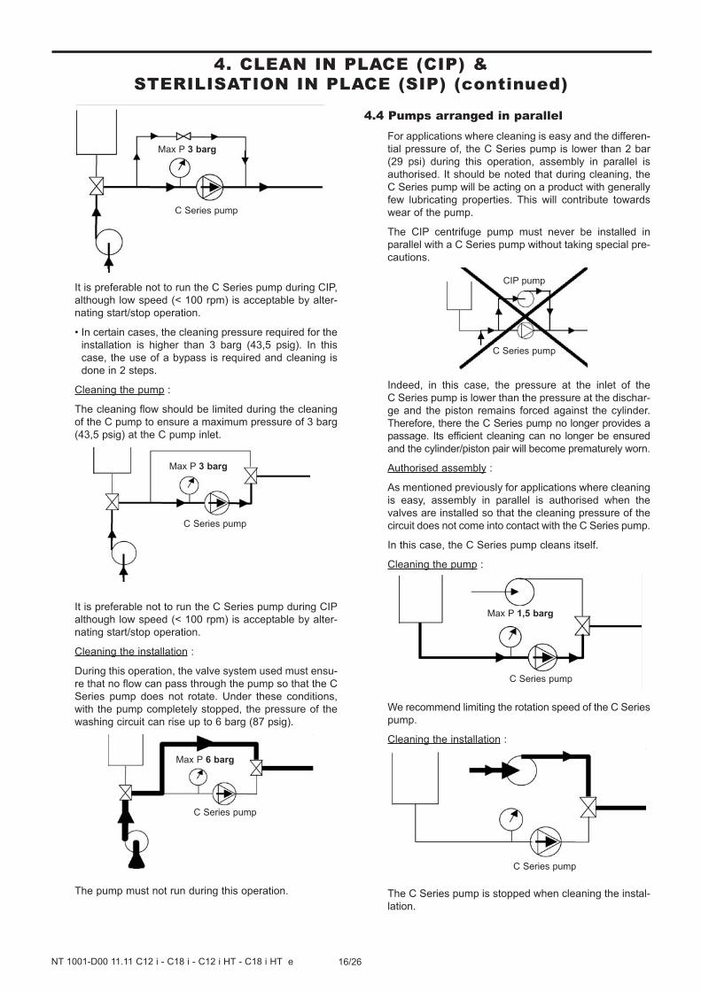
4. CLEAN IN PLACE (CIP) & STERILISATION IN PLACE (SIP) (continued)
It is preferable not to run the C Series pump during CIP,
although low speed (< 100 rpm) is acceptable by alter-
nating start/stop operation.
• In certain cases, the cleaning pressure required for the
installation is higher than 3 barg (43,5 psig). In this
case, the use of a bypass is required and cleaning is
done in 2 steps.
Cleaning the pump :
The cleaning flow should be limited during the cleaning
of the C pump to ensure a maximum pressure of 3 barg
(43,5 psig) at the C pump inlet.
It is preferable not to run the C Series pump during CIP
although low speed (< 100 rpm) is acceptable by alter-
nating start/stop operation.
Cleaning the installation :
During this operation, the valve system used must ensu-
re that no flow can pass through the pump so that the C
Series pump does not rotate. Under these conditions,
with the pump completely stopped, the pressure of the
washing circuit can rise up to 6 barg (87 psig).
The pump must not run during this operation.
4.4 Pumps arranged in parallelFor applications where cleaning is easy and the differen-
tial pressure of, the C Series pump is lower than 2 bar
(29 psi) during this operation, assembly in parallel is
authorised. It should be noted that during cleaning, the
C Series pump will be acting on a product with generally
few lubricating properties. This will contribute towards
wear of the pump.
The CIP centrifuge pump must never be installed in
parallel with a C Series pump without taking special pre-
cautions.
Indeed, in this case, the pressure at the inlet of the
C Series pump is lower than the pressure at the dischar-
ge and the piston remains forced against the cylinder.
Therefore, there the C Series pump no longer provides a
passage. Its efficient cleaning can no longer be ensured
and the cylinder/piston pair will become prematurely worn.
Authorised assembly :
As mentioned previously for applications where cleaning
is easy, assembly in parallel is authorised when the
valves are installed so that the cleaning pressure of the
circuit does not come into contact with the C Series pump.
In this case, the C Series pump cleans itself.
Cleaning the pump :
We recommend limiting the rotation speed of the C Series
pump.
Cleaning the installation :
The C Series pump is stopped when cleaning the instal-
lation.
C Series pump
C Series pump
Max P 1,5 barg
C Series pump
Max P 6 barg
C Series pump
Max P 3 barg
CIP pump
C Series pump
C Series pump
Max P 3 barg
17/26NT 1001-D00 11.11 C12 i - C18 i - C12 i HT - C18 i HT e
4.5 Successive cyclesGenerally, the most efficient CIPs comprise 5 stages :
1. Pre-washing with clean water
Water at room temperature. 10 to 15 minute cycle. This
pre-wash enables evacuation of the remaining residues.
2. Washing with an alkaline detergent
Typically this is soda at 2,5% at a temperature of 80°C.
20 to 30 minute cycle. This wash particularly enables
dissolving and evacuating grease and proteins.
3. Rinsing with clean water
Water at room temperature. 10 minute cycle. This rinse
enables avoiding the mixture of 2 cleaning solutions.
4. Washing with an acid solution
Typically this is nitric acid at 2,5% at room temperature.
10 to 15 minute cycle. This wash particularly enables
dissolving and evacuating proteins and inorganic salts.
5. Rinsing with clean water
Water at room temperature. Several 1 to 2 minute
cycles. These rinses enable evacuating all traces of
acid solution.
During all these CIP stages, the average speeds of the
cleaning liquids in the pipes must be between 1,5 and 3 m/s.
4.6 Sterilisation In Place (SIP)The serie C pumps are perfectly adapted to all processes
using SIP (Sterilisation In Place) : pump stopped / maxi-
mum 30 min per cycle / 1 or 2 cycles per day.
4. CLEAN IN PLACE (CIP) & STERILISATION IN PLACE (SIP) (continued)
5.1 Necessary tools• 24 Socket wrench
• 13-32 Open-end spanner
• Hub puller
• 70 Open-end spanner or Monkey wrench
Tightened torques :
• M8 : 18 Nm
• M16 : 100 Nm
• M24 : 200 Nm
5. MAINTENANCE
18/26NT 1001-D00 11.11 C12 i - C18 i - C12 i HT - C18 i HT e
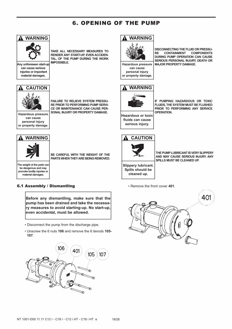
6.1 Assembly / Dismantling
• Disconnect the pump from the discharge pipe.
• Unscrew the 6 nuts 106 and remove the 6 tierods 105-
107.
• Remove the front cover 401.
Before any dismantling, make sure that the
pump has been drained and take the necessa-
ry measures to avoid starting-up. No start-up,
even accidental, must be allowed.
6. OPENING OF THE PUMP
TAKE ALL NECESSARY MEASURES TO
RENDER ANY START-UP, EVEN ACCIDEN-
TAL, OF THE PUMP DURING THE WORK
IMPOSSIBLE.
WARNING
Any unforeseen start-up
can cause serious
injuries or important
material damages.
FAILURE TO RELIEVE SYSTEM PRESSU-
RE PRIOR TO PERFORMING PUMP SERVI-
CE OR MAINTENANCE CAN CAUSE PER-
SONAL INJURY OR PROPERTY DAMAGE.
CAUTION
Hazardous pressure
can cause
personal injury
or property damage.
BE CAREFUL WITH THE WEIGHT OF THE
PARTS WHEN THEY ARE BEING REMOVED.
WARNING
The weight ot the parts can
be dangerous and may
provoke bodily injuries or
material damages.
DISCONNECTING THE FLUID OR PRESSU-
RE CONTAINMENT COMPONENTS
DURING PUMP OPERATION CAN CAUSE
SERIOUS PERSONAL INJURY, DEATH OR
MAJOR PROPERTY DAMAGE.
WARNING
Hazardous pressure
can cause
personal injury
or property damage.
IF PUMPING HAZARDOUS OR TOXIC
FLUIDS, THE SYSTEM MUST BE FLUSHED
PRIOR TO PERFORMING ANY SERVICE
OPERATION.
WARNING
Hazardous or toxic
fluids can cause
serious injury.
THE PUMP LUBRICANT IS VERY SLIPPERY
AND MAY CAUSE SERIOUS INJURY. ANY
SPILLS MUST BE CLEANED UP.
CAUTION
Slippery lubricant.
Spills should be
cleaned up.
19/26NT 1001-D00 11.11 C12 i - C18 i - C12 i HT - C18 i HT e
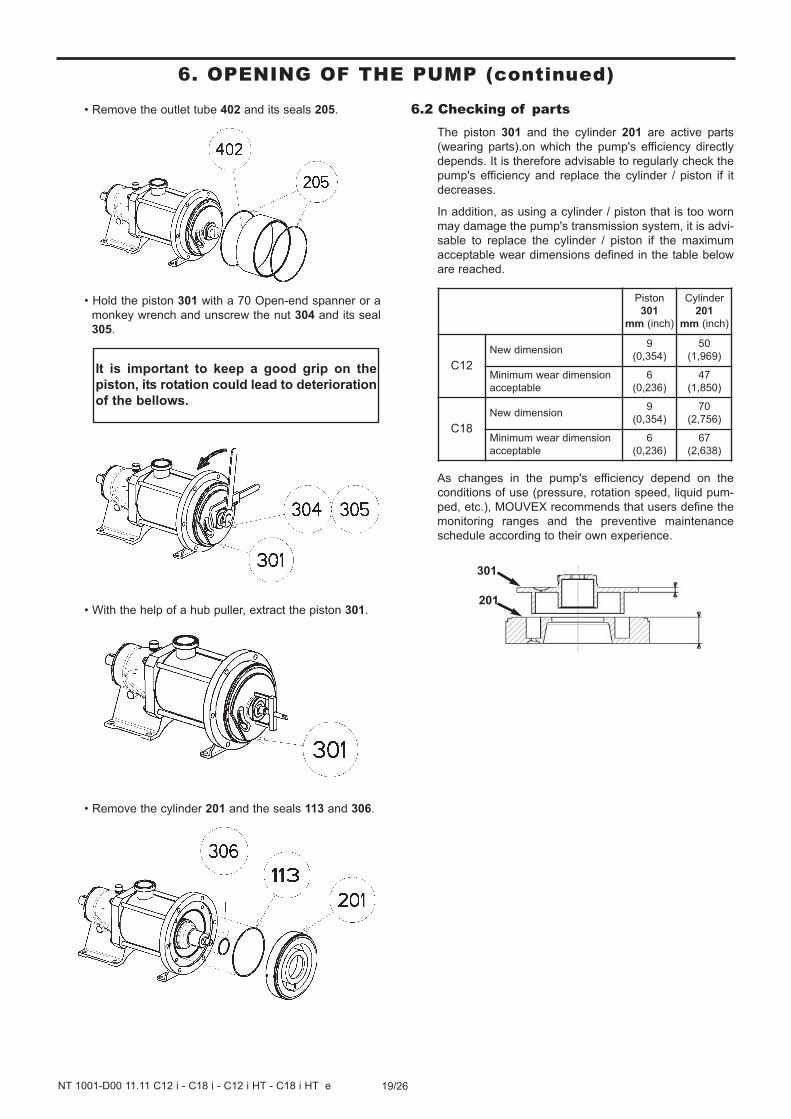
• Remove the outlet tube 402 and its seals 205.
• Hold the piston 301 with a 70 Open-end spanner or a
monkey wrench and unscrew the nut 304 and its seal
305.
• With the help of a hub puller, extract the piston 301.
• Remove the cylinder 201 and the seals 113 and 306.
6.2 Checking of partsThe piston 301 and the cylinder 201 are active parts
(wearing parts).on which the pump's efficiency directly
depends. It is therefore advisable to regularly check the
pump's efficiency and replace the cylinder / piston if it
decreases.
In addition, as using a cylinder / piston that is too worn
may damage the pump's transmission system, it is advi-
sable to replace the cylinder / piston if the maximum
acceptable wear dimensions defined in the table below
are reached.
As changes in the pump's efficiency depend on the
conditions of use (pressure, rotation speed, liquid pum-
ped, etc.), MOUVEX recommends that users define the
monitoring ranges and the preventive maintenance
schedule according to their own experience.
It is important to keep a good grip on the
piston, its rotation could lead to deterioration
of the bellows.
Piston
301
mm (inch)
Cylinder
201
mm (inch)
C12
New dimension9
(0,354)
50
(1,969)
Minimum wear dimension
acceptable
6
(0,236)
47
(1,850)
C18
New dimension9
(0,354)
70
(2,756)
Minimum wear dimension
acceptable
6
(0,236)
67
(2,638)
301
201
6. OPENING OF THE PUMP (continued)
20/26NT 1001-D00 11.11 C12 i - C18 i - C12 i HT - C18 i HT e
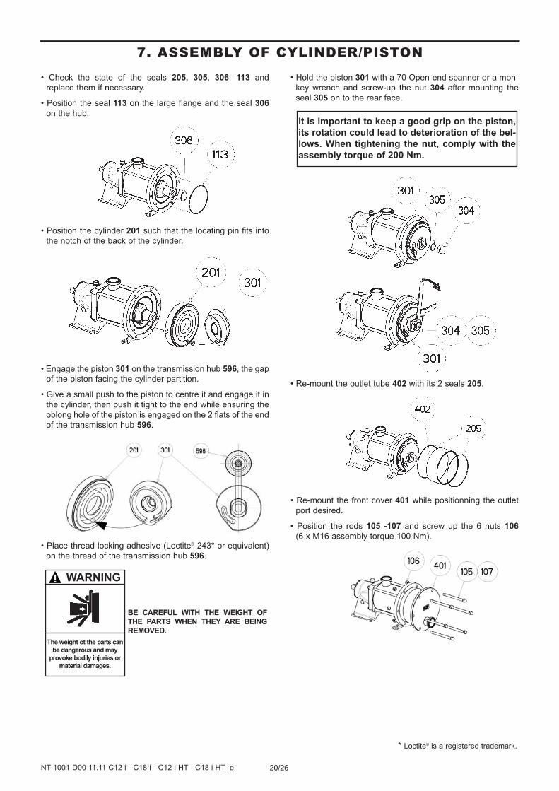
7. ASSEMBLY OF CYLINDER/PISTON
• Check the state of the seals 205, 305, 306, 113 and
replace them if necessary.
• Position the seal 113 on the large flange and the seal 306
on the hub.
• Position the cylinder 201 such that the locating pin fits into
the notch of the back of the cylinder.
• Engage the piston 301 on the transmission hub 596, the gap
of the piston facing the cylinder partition.
• Give a small push to the piston to centre it and engage it in
the cylinder, then push it tight to the end while ensuring the
oblong hole of the piston is engaged on the 2 flats of the end
of the transmission hub 596.
• Place thread locking adhesive (Loctite® 243* or equivalent)
on the thread of the transmission hub 596.
• Hold the piston 301 with a 70 Open-end spanner or a mon-
key wrench and screw-up the nut 304 after mounting the
seal 305 on to the rear face.
• Re-mount the outlet tube 402 with its 2 seals 205.
• Re-mount the front cover 401 while positionning the outlet
port desired.
• Position the rods 105 -107 and screw up the 6 nuts 106
(6 x M16 assembly torque 100 Nm).
It is important to keep a good grip on the piston,
its rotation could lead to deterioration of the bel-
lows. When tightening the nut, comply with the
assembly torque of 200 Nm.
WARNING
The weight ot the parts can
be dangerous and may
provoke bodily injuries or
material damages.
BE CAREFUL WITH THE WEIGHT OF
THE PARTS WHEN THEY ARE BEING
REMOVED.
* Loctite® is a registered trademark.
21/26NT 1001-D00 11.11 C12 i - C18 i - C12 i HT - C18 i HT e
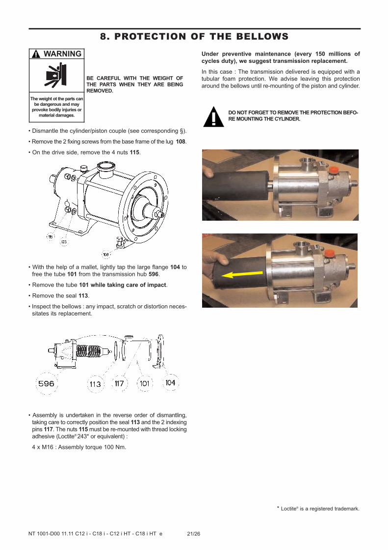
8. PROTECTION OF THE BELLOWS
• Dismantle the cylinder/piston couple (see corresponding §).
• Remove the 2 fixing screws from the base frame of the lug 108.
• On the drive side, remove the 4 nuts 115.
• With the help of a mallet, lightly tap the large flange 104 to
free the tube 101 from the transmission hub 596.
• Remove the tube 101 while taking care of impact.
• Remove the seal 113.
• Inspect the bellows : any impact, scratch or distortion neces-
sitates its replacement.
• Assembly is undertaken in the reverse order of dismantling,
taking care to correctly position the seal 113 and the 2 indexing
pins 117. The nuts 115 must be re-mounted with thread locking
adhesive (Loctite® 243* or equivalent) :
4 x M16 : Assembly torque 100 Nm.
Under preventive maintenance (every 150 millions of
cycles duty), we suggest transmission replacement.
In this case : The transmission delivered is equipped with a
tubular foam protection. We advise leaving this protection
around the bellows until re-mounting of the piston and cylinder.
WARNING
The weight ot the parts can
be dangerous and may
provoke bodily injuries or
material damages.DO NOT FORGET TO REMOVE THE PROTECTION BEFO-
RE MOUNTING THE CYLINDER.
BE CAREFUL WITH THE WEIGHT OF
THE PARTS WHEN THEY ARE BEING
REMOVED.
* Loctite® is a registered trademark.
22/26NT 1001-D00 11.11 C12 i - C18 i - C12 i HT - C18 i HT e
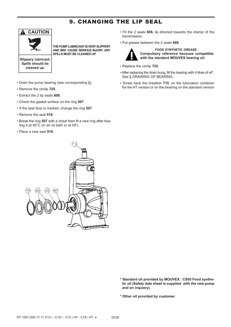
• Drain the pump bearing (see corresponding §).
• Remove the circlip 725.
• Extract the 2 lip seals 608.
• Check the gasket surface on the ring 507.
• If the seal face is marked, change the ring 507.
• Remove the seal 518.
• Break the ring 507 with a chisel then fit a new ring after hea-
ting it at 95°C (in an oil bath or at HF).
• Place a new seal 518.
• Fit the 2 seals 608, lip directed towards the interior of the
transmission.
• Put grease between the 2 seals 608.
• Replace the circlip 725.
• After replacing the drain bung, fill the bearing with 4 litres of oil*.
See § DRAINING OF BEARING..
• Screw back the breather 715. on the lubrication container
for the HT version or on the beairing on the standard version
* Standard oil provided by MOUVEX : CS05 Food synthe-
tic oil (Safety data sheet is supplied with the new pump
and on inquiery).
* Other oil provided by customer.
FOOD SYNTHETIC GREASE :
Compulsory reference because compatible
with the standard MOUVEX bearing oil.
THE PUMP LUBRICANT IS VERY SLIPPERY
AND MAY CAUSE SERIOUS INJURY. ANY
SPILLS MUST BE CLEANED UP.
CAUTION
Slippery lubricant.
Spills should be
cleaned up.
9. CHANGING THE LIP SEAL
23/26NT 1001-D00 11.11 C12 i - C18 i - C12 i HT - C18 i HT e
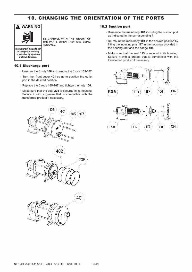
10.1 Discharge port• Unscrew the 6 nuts 106 and remove the 6 rods 105-107.
• Turn the front cover 401 so as to position the outlet
port in the desired position.
• Replace the 6 rods 105-107 and tighten the nuts 106.
• Make sure that the seal 205 is secured in its housing.
Secure it with a grease that is compatible with the
transferred product if necessary.
10.2 Suction port• Dismantle the main body 101 including the suction port
as indicated in the corresponding §.
• Re-mount the main body 101 in the desired position by
fitting the indexing pins 117 in the housings provided in
the bearing 596 and the flange 104.
• Make sure that the seal 113 is secured in its housing.
Secure it with a grease that is compatible with the
transferred product if necessary.
BE CAREFUL WITH THE WEIGHT OF
THE PARTS WHEN THEY ARE BEING
REMOVED.
WARNING
The weight ot the parts can
be dangerous and may
provoke bodily injuries or
material damages.
10. CHANGING THE ORIENTATION OF THE PORTS
24/26NT 1001-D00 11.11 C12 i - C18 i - C12 i HT - C18 i HT e
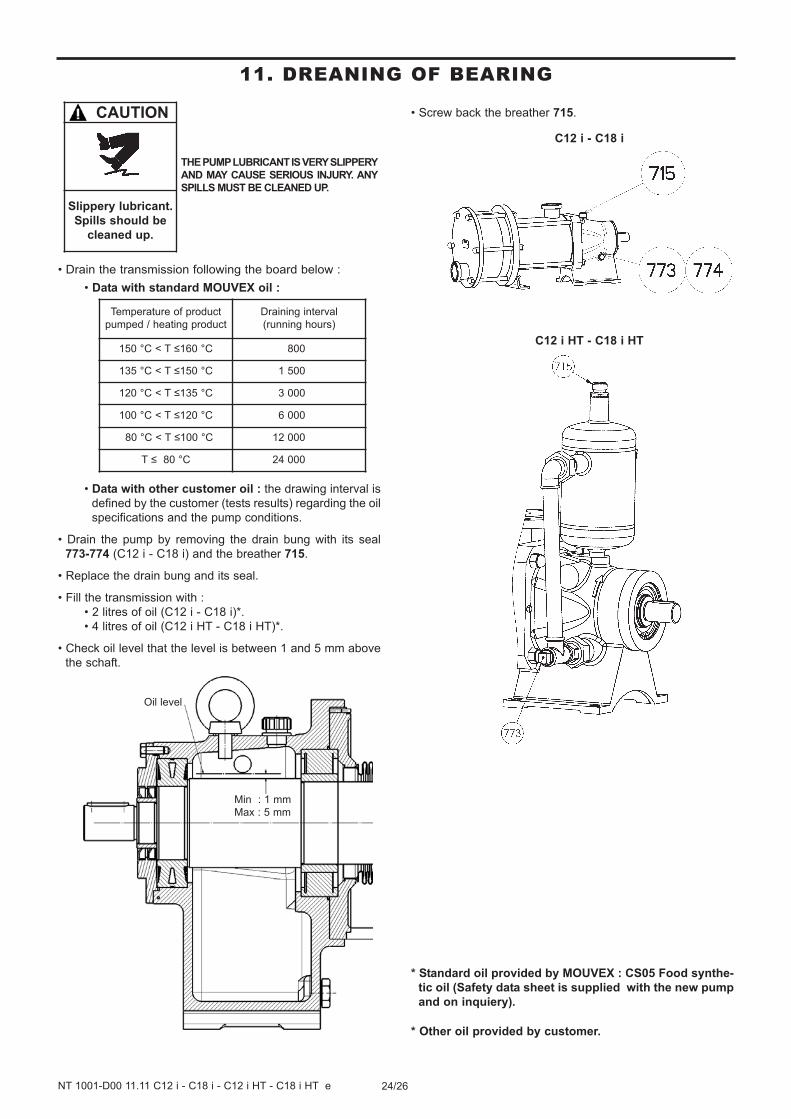
• Drain the transmission following the board below :
• Data with standard MOUVEX oil :
• Data with other customer oil : the drawing interval is
defined by the customer (tests results) regarding the oil
specifications and the pump conditions.
• Drain the pump by removing the drain bung with its seal
773-774 (C12 i - C18 i) and the breather 715.
• Replace the drain bung and its seal.
• Fill the transmission with :
• 2 litres of oil (C12 i - C18 i)*.
• 4 litres of oil (C12 i HT - C18 i HT)*.
• Check oil level that the level is between 1 and 5 mm above
the schaft.
• Screw back the breather 715.
C12 i - C18 i
C12 i HT - C18 i HT
* Standard oil provided by MOUVEX : CS05 Food synthe-
tic oil (Safety data sheet is supplied with the new pump
and on inquiery).
* Other oil provided by customer.
Oil level
Min : 1 mm
Max : 5 mm
Temperature of product
pumped / heating product
Draining interval
(running hours)
150 °C < T ≤160 °C 800
135 °C < T ≤150 °C 1 500
120 °C < T ≤135 °C 3 000
100 °C < T ≤120 °C 6 000
80 °C < T ≤100 °C 12 000
T ≤ 80 °C 24 000
THE PUMP LUBRICANT IS VERY SLIPPERY
AND MAY CAUSE SERIOUS INJURY. ANY
SPILLS MUST BE CLEANED UP.
CAUTION
Slippery lubricant.
Spills should be
cleaned up.
11. DREANING OF BEARING
25/26NT 1001-D00 11.11 C12 i - C18 i - C12 i HT - C18 i HT e
12. OPTIONS
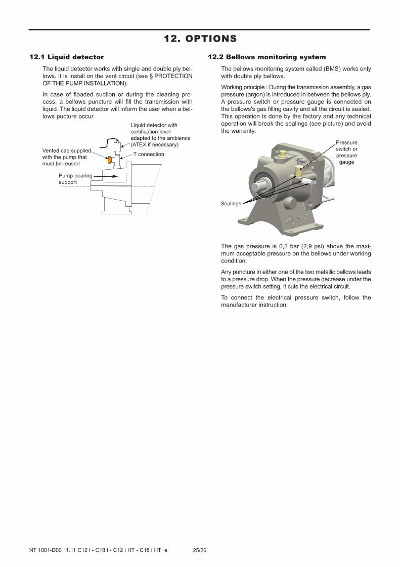
12.1 Liquid detectorThe liquid detector works with single and double ply bel-
lows. It is install on the vent circuit (see § PROTECTION
OF THE PUMP INSTALLATION).
In case of floaded suction or during the cleaning pro-
cess, a bellows puncture will fill the transmission with
liquid. The liquid detector will inform the user when a bel-
lows pucture occur.
12.2 Bellows monitoring systemThe bellows monitoring system called (BMS) works only
with double ply bellows.
Working principle : During the transmission assembly, a gas
pressure (argon) is introduced in between the bellows ply.
A pressure switch or pressure gauge is connected on
the bellows's gas filling cavity and all the circuit is sealed.
This operation is done by the factory and any technical
operation will break the sealings (see picture) and avoid
the warranty.
The gas pressure is 0,2 bar (2,9 psi) above the maxi-
mum acceptable pressure on the bellows under working
condition.
Any puncture in either one of the two metallic bellows leads
to a pressure drop. When the pressure decrease under the
pressure switch setting, it cuts the electrical circuit.
To connect the electrical pressure switch, follow the
manufacturer instruction.
Vented cap supplied
with the pump that
must be reused
Liquid detector with
certification level
adapted to the ambience
(ATEX if necessary)
T connection
Pump bearing
support
Pressure
switch or
pressure
gauge
Sealings
26/26NT 1001-D00 11.11 C12 i - C18 i - C12 i HT - C18 i HT e
CUM 220103 FORM-QUA-18-4
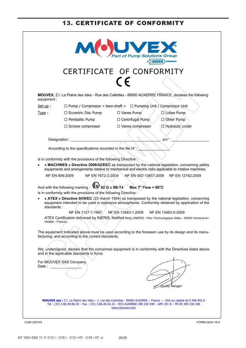
CERTIFICATE OF CONFORMITY
MOUVEX, Z.I. La Plaine des Isles - Rue des Caillottes - 89000 AUXERRE FRANCE, declares the following equipment :
Set-up : Pump / Compressor « bare-shaft » Pumping Unit / Compressor Unit
Type : Eccentric Disc Pump Vanes Pump Lobes Pump
Peristaltic Pump Centrifugal Pump Other Pump
Screws compressor Vanes compressor Hydraulic cooler
Designation : s/n° :
According to the specifications recorded in the file N° : _
is in conformity with the provisions of the following Directive :
« MACHINES » Directive 2006/42/EEC as transposed by the national legislation, concerning safety equipments and arrangements relative to mechanical and electric risks applicable to rotative machines.
NF EN 809:2009 NF EN 1672-2:2009 NF EN ISO 13857:2008 NF EN 12162:2009
And with the following marking : II2 G c IIB-T4 Max T° Flow = 80°C
is in conformity with the provisions of the following Directive :
« ATEX » Directive 94/9/EC (23 march 1994) as transposed by the national legislation, concerning equipment intended to be used in explosive atmospheres. Conformity obtained by application of the standards :
NF EN 1127-1:1997 NF EN 13463-1:2009 NF EN 13463-5:2009
ATEX Certification delivered by INERIS, Notified Body (INERIS - Parc Technologique Alata – 60550 Verneuil-en-Halatte - France).
The equipment indicated above must be used according to the foreseen use by its design and its manu-facturing, and according to the current standards. We, undersigned, declare that the concerned equipment is in conformity with the Directives listed above and in the applicable standards in force. For MOUVEX SAS Company. Date : _______________
Quality Manager
MOUVEX sas : Z.I. La Plaine des Isles – 2, rue des Caillottes - 89000 AUXERRE – France – SAS au capital de 8 496 855 € Tél : (33) 3.86.49.86.30 – Fax : (33) 3.86.46.42.10 – RCS AUXERRE 389 236 548 – APE 291 B – FR 85 389 236 548
www.mouvex.com
13. CERTIFICATE OF CONFORMITY