C1000 Inlet Valve Assembly - Ingersoll Rand...
24
CENTAC C1000 Inlet Valve Assembly C.C.N. : 80445943 REV. : A DATE : SEPTEMBER 2010
Transcript of C1000 Inlet Valve Assembly - Ingersoll Rand...

CENTAC
C1000 Inlet Valve Assembly
C.C.N. : 80445943 REV. : A DATE : SEPTEMBER 2010

2 C1000 INLET VALVE ASSEMBLY
80445943-A EN ingersollrandproducts.com
Table of Contents Table of Contents ......................................................................................................................................... 2 Introduction .................................................................................................................................................. 3 Part I: The Positioner ................................................................................................................................... 4
Valve Positioner Operating Principle ......................................................................................................... 4 Cam .......................................................................................................................................................... 5 Pneumatic & Feedback Cam Installation................................................................................................... 7 Electrical Wiring ........................................................................................................................................ 8 Positioner Technical Specifications: .......................................................................................................... 9 Valve Positioner Exploded View .............................................................................................................. 10
Part II: The Actuator .................................................................................................................................. 11 Actuator Operating Principle ................................................................................................................... 11 Actuator Parts Identification List .............................................................................................................. 13
Part III: The Valve ...................................................................................................................................... 15 Standard "Wafer" Type Butterfly Inlet Valve characteristics .................................................................... 15
Part IV: The Regulator and Coalescing Filter .......................................................................................... 16 Supply Air Regulator (mounted on Panel Side) ....................................................................................... 16 Coalescing Filter (mounted on Panel Side) ............................................................................................. 16 Inlet and Bypass Valves Calibration ........................................................................................................ 17
Part V: Adjustments and Maintenance ....................................................................................................... 19 Tools and Materials Needed ................................................................................................................... 19 Stroking the Inlet and Bypass Valve Assembly ....................................................................................... 19 Routine Maintenance .............................................................................................................................. 20
Notices and Disclaimers ............................................................................................................................. 20 Copyright Notice ..................................................................................................................................... 20 Proprietary Notices ................................................................................................................................. 20 Disclaimers ............................................................................................................................................. 20
C1000 BYPASS VALVE ASSEMBLY 3
80445943-A EN ingersollrandproducts.com
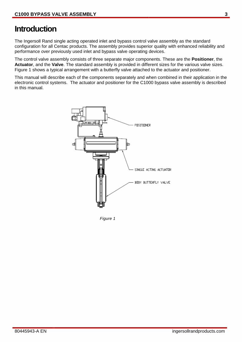
Introduction The Ingersoll Rand single acting operated inlet and bypass control valve assembly as the standard configuration for all Centac products. The assembly provides superior quality with enhanced reliability and performance over previously used inlet and bypass valve operating devices.
The control valve assembly consists of three separate major components. These are the Positioner, the Actuator, and the Valve. The standard assembly is provided in different sizes for the various valve sizes. Figure 1 shows a typical arrangement with a butterfly valve attached to the actuator and positioner.
This manual will describe each of the components separately and when combined in their application in the electronic control systems. The actuator and positioner for the C1000 bypass valve assembly is described in this manual.
Figure 1
4 C1000 INLET VALVE ASSEMBLY
80445943-A EN ingersollrandproducts.com
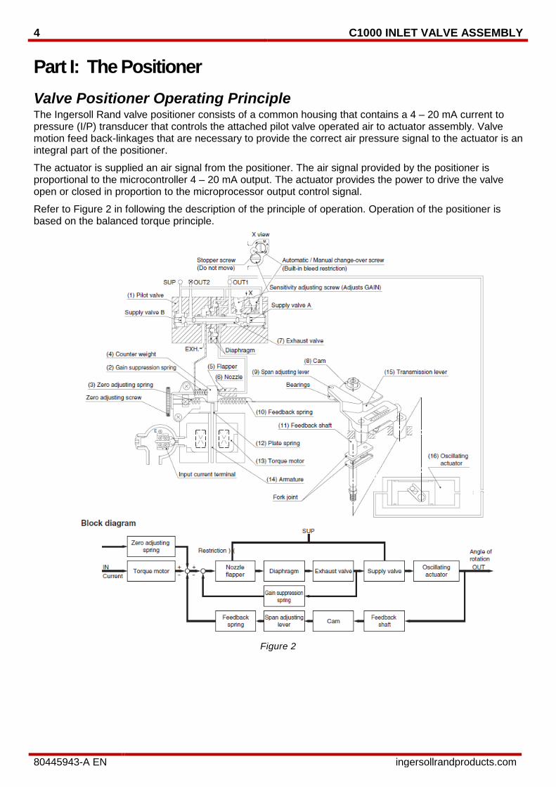
Part I: The Positioner Valve Positioner Operating Principle The Ingersoll Rand valve positioner consists of a common housing that contains a 4 – 20 mA current to pressure (I/P) transducer that controls the attached pilot valve operated air to actuator assembly. Valve motion feed back-linkages that are necessary to provide the correct air pressure signal to the actuator is an integral part of the positioner.
The actuator is supplied an air signal from the positioner. The air signal provided by the positioner is proportional to the microcontroller 4 – 20 mA output. The actuator provides the power to drive the valve open or closed in proportion to the microprocessor output control signal.
Refer to Figure 2 in following the description of the principle of operation. Operation of the positioner is based on the balanced torque principle.
Figure 2
C1000 BYPASS VALVE ASSEMBLY 5
80445943-A EN ingersollrandproducts.com
When the input current increases, (12) the plate spring of (13) the torque motor will work as a pivot, (14) armature will receive a counter-clockwise torque, (4) the counter weight will be pushed to the left and the clearance between (6) the nozzle and (5) the flapper will increase, and the nozzle back pressure will decrease. Consequently, (7) the exhaust valve of (1) the pilot valve moves to the right, the output pressure of OUT1 increases and the rotary actuator moves. The motion of (16) the actuator acts on (10) the feedback spring through (11) the feedback shaft, (8) the cam, (9) the span adjustment lever and (15) transmission lever to rest at the balance position generated by the input current. (8) The cam is set on the RA surface and operates reverse while (16) the oscillating actuator shaft rotates in a counterclockwise direction when the input signal is increased. (2) The gain suppression spring is for direct feedback of the motion of (7) the exhaust valve to (4) the counter weight to increase the stability of the loop. The zero point should be adjusted by change of (3) the zero adjustment spring tension.
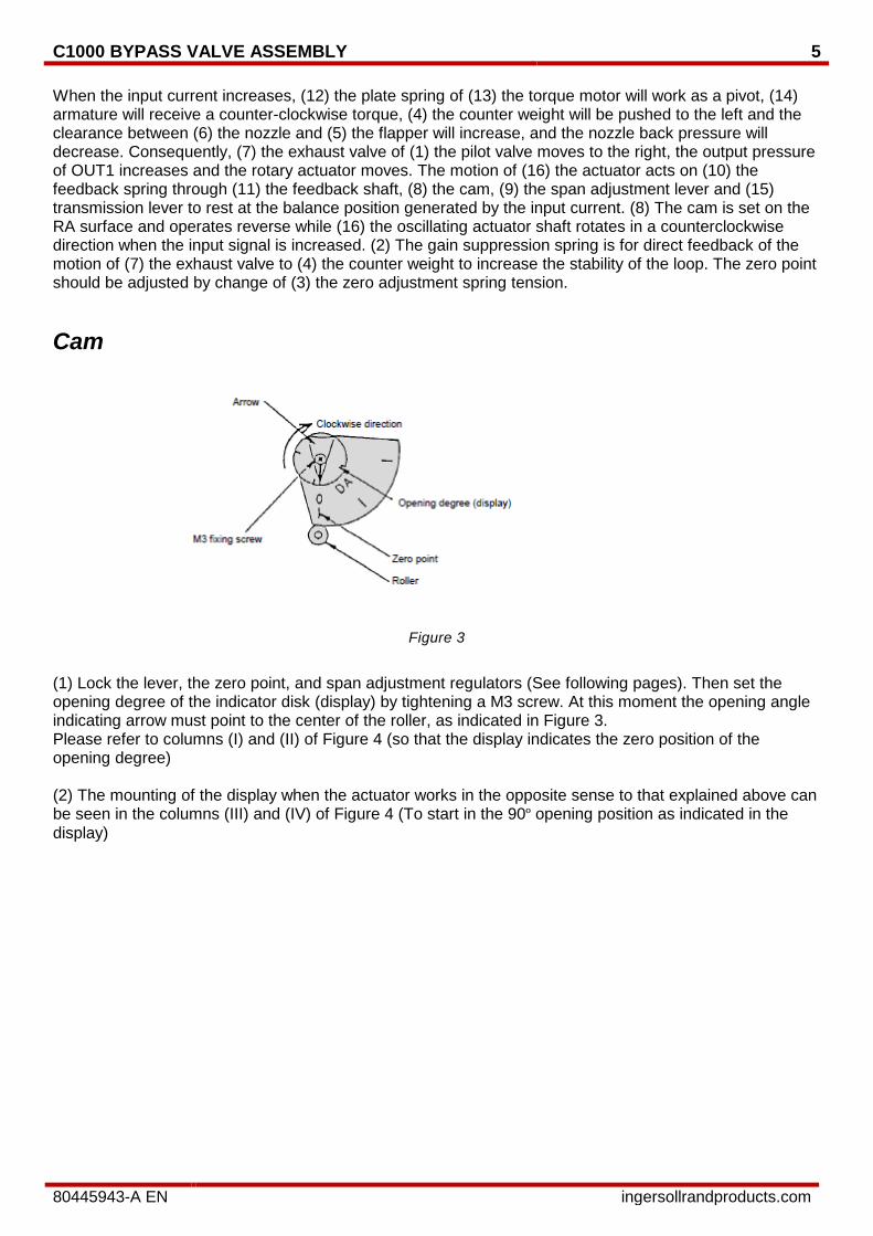
Cam
Figure 3
(1) Lock the lever, the zero point, and span adjustment regulators (See following pages). Then set the opening degree of the indicator disk (display) by tightening a M3 screw. At this moment the opening angle indicating arrow must point to the center of the roller, as indicated in Figure 3. Please refer to columns (I) and (II) of Figure 4 (so that the display indicates the zero position of the opening degree) (2) The mounting of the display when the actuator works in the opposite sense to that explained above can be seen in the columns (III) and (IV) of Figure 4 (To start in the 90º opening position as indicated in the display)
6 C1000 INLET VALVE ASSEMBLY
80445943-A EN ingersollrandproducts.com
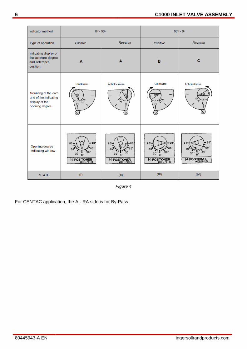
Figure 4
For CENTAC application, the A - RA side is for By-Pass
C1000 BYPASS VALVE ASSEMBLY 7
80445943-A EN ingersollrandproducts.com
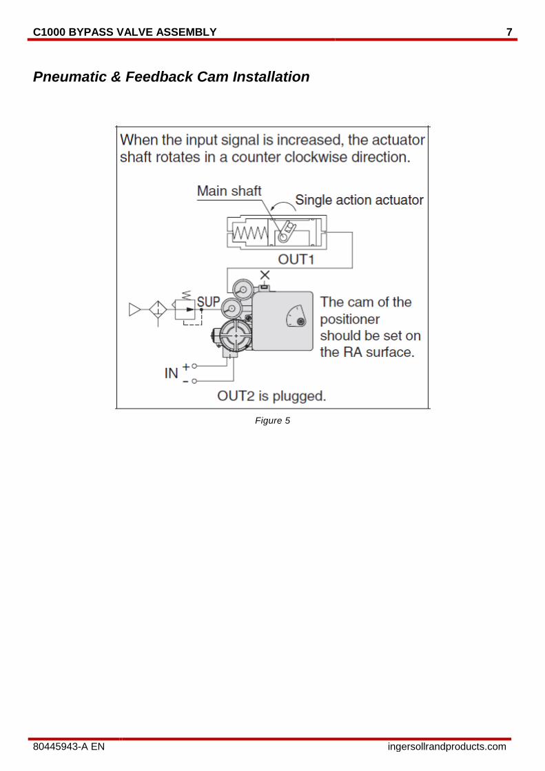
Pneumatic & Feedback Cam Installation
Figure 5
8 C1000 INLET VALVE ASSEMBLY
80445943-A EN ingersollrandproducts.com
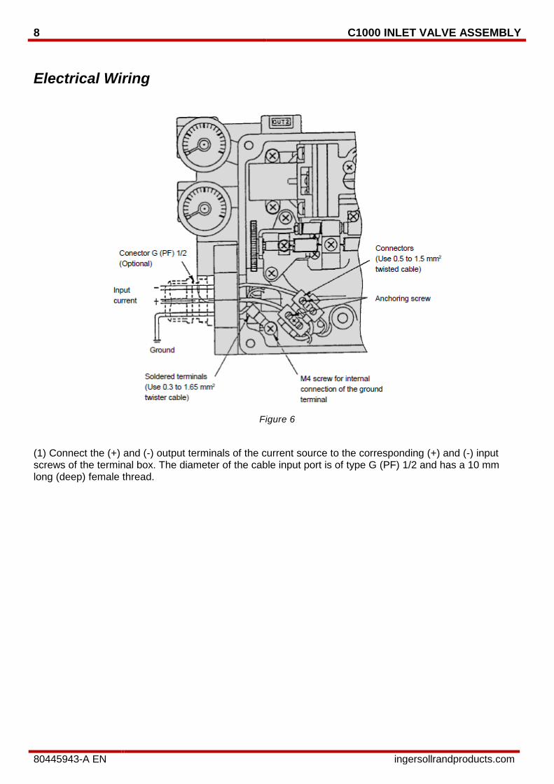
Electrical Wiring
Figure 6
(1) Connect the (+) and (-) output terminals of the current source to the corresponding (+) and (-) input screws of the terminal box. The diameter of the cable input port is of type G (PF) 1/2 and has a 10 mm long (deep) female thread.
C1000 BYPASS VALVE ASSEMBLY 9
80445943-A EN ingersollrandproducts.com
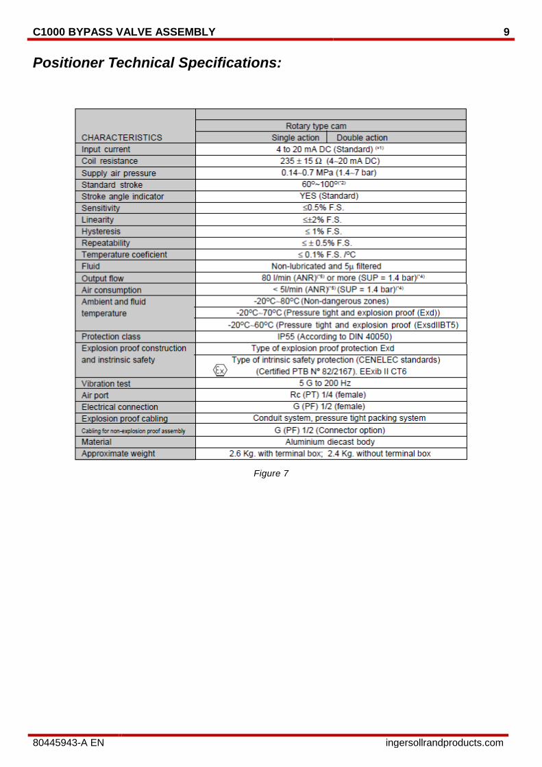
Positioner Technical Specifications:
Figure 7
10 C1000 INLET VALVE ASSEMBLY
80445943-A EN ingersollrandproducts.com
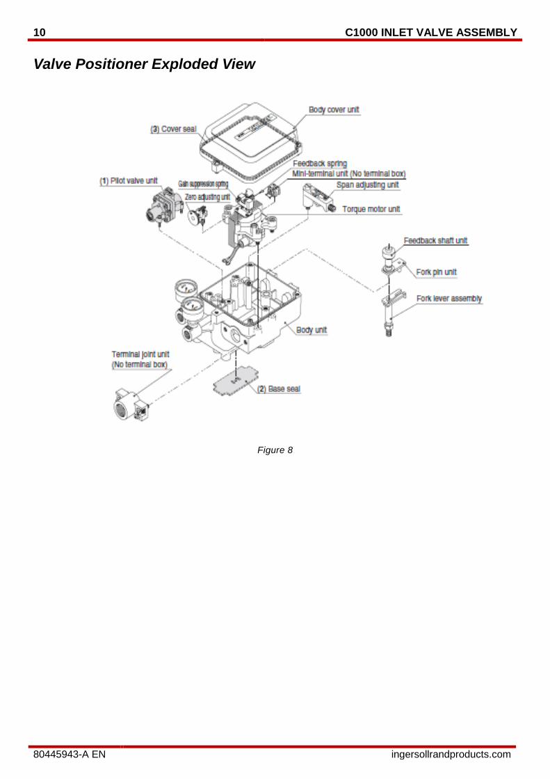
Valve Positioner Exploded View
Figure 8
C1000 BYPASS VALVE ASSEMBLY 11
80445943-A EN ingersollrandproducts.com
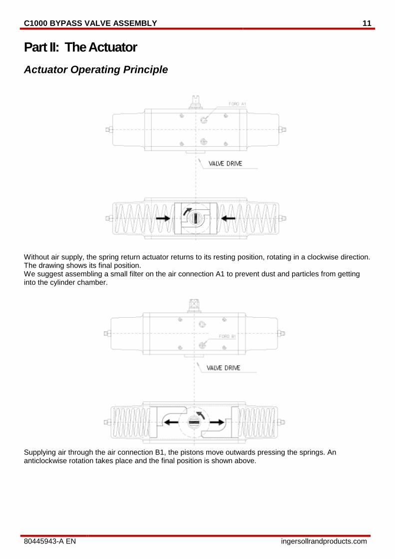
Part II: The Actuator Actuator Operating Principle
Without air supply, the spring return actuator returns to its resting position, rotating in a clockwise direction. The drawing shows its final position. We suggest assembling a small filter on the air connection A1 to prevent dust and particles from getting into the cylinder chamber.
Supplying air through the air connection B1, the pistons move outwards pressing the springs. An anticlockwise rotation takes place and the final position is shown above.
12 C1000 INLET VALVE ASSEMBLY
80445943-A EN ingersollrandproducts.com
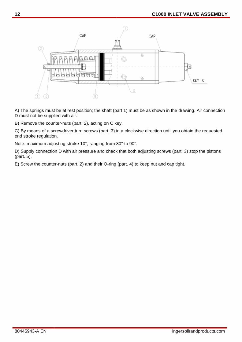
A) The springs must be at rest position; the shaft (part 1) must be as shown in the drawing. Air connection D must not be supplied with air.
B) Remove the counter-nuts (part. 2), acting on C key.
C) By means of a screwdriver turn screws (part. 3) in a clockwise direction until you obtain the requested end stroke regulation.
Note: maximum adjusting stroke 10°, ranging from 80° to 90°.
D) Supply connection D with air pressure and check that both adjusting screws (part. 3) stop the pistons (part. 5).
E) Screw the counter-nuts (part. 2) and their O-ring (part. 4) to keep nut and cap tight.

C1000 BYPASS VALVE ASSEMBLY 13
80445943-A EN ingersollrandproducts.com
Actuator Parts Identification List
Figure 9

14 C1000 INLET VALVE ASSEMBLY
80445943-A EN ingersollrandproducts.com
C1000 BYPASS VALVE ASSEMBLY 15
80445943-A EN ingersollrandproducts.com
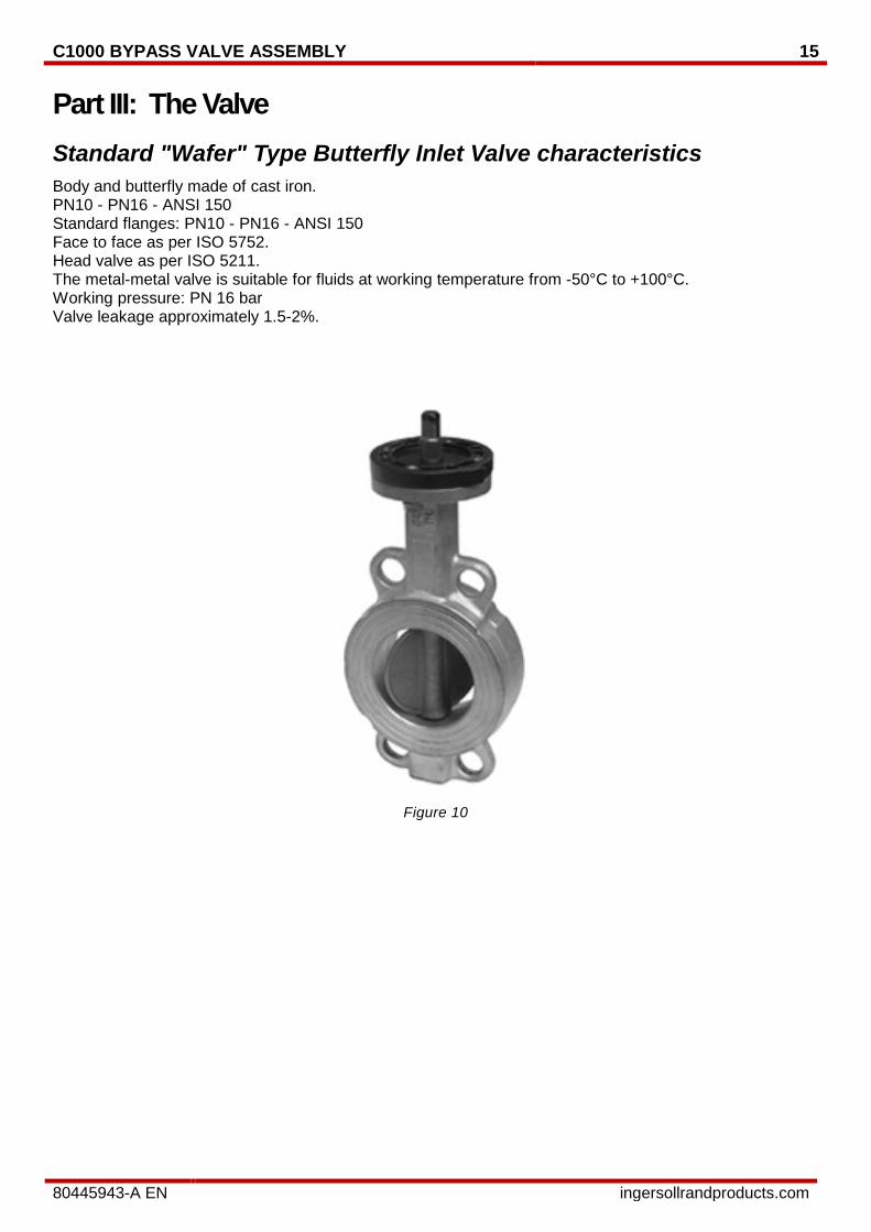
Part III: The Valve Standard "Wafer" Type Butterfly Inlet Valve characteristics Body and butterfly made of cast iron. PN10 - PN16 - ANSI 150 Standard flanges: PN10 - PN16 - ANSI 150 Face to face as per ISO 5752. Head valve as per ISO 5211. The metal-metal valve is suitable for fluids at working temperature from -50°C to +100°C. Working pressure: PN 16 bar Valve leakage approximately 1.5-2%.
Figure 10
16 C1000 INLET VALVE ASSEMBLY
80445943-A EN ingersollrandproducts.com
Part IV: The Regulator and Coalescing Filter Supply Air Regulator (mounted on Panel Side)
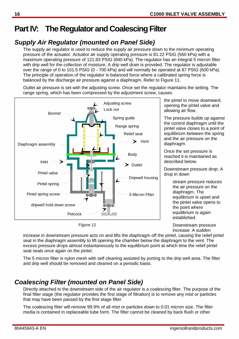
The supply air regulator is used to reduce the supply air pressure down to the minimum operating pressure of the actuator. Actuator air supply operating pressure is 81.22 PSIG (560 kPa) with a maximum operating pressure of 121.83 PSIG (840 kPa). The regulator has an integral 5 micron filter with drip well for the collection of moisture. A drip well drain is provided. The regulator is adjustable over the range of 0 to 101.5 PSIG (0 - 700 kPa) and will normally be operated at 87 PSIG (600 kPa). The principle of operation of the regulator is balanced force where a calibrated spring force is balanced by the discharge air pressure against a diaphragm. Refer to Figure 11.
Outlet air pressure is set with the adjusting screw. Once set the regulator maintains the setting. The range spring, which has been compressed by the adjustment screw, causes
the pintel to move downward, opening the pintel valve and allowing air flow.
The pressure builds up against the control diaphragm until the pintel valve closes to a point of equilibrium between the spring and the air pressure on the diaphragm.
Once the set pressure is reached it is maintained as described below.
Downstream pressure drop: A drop in down
stream pressure reduces the air pressure on the diaphragm. The equilibrium is upset and the pintel valve opens to the point where equilibrium is again established.
Downstream pressure increase: A sudden
increase in downstream pressure acts on and lifts the diaphragm off the pintel, causing the relief pintel seat in the diaphragm assembly to lift opening the chamber below the diaphragm to the vent. The excess pressure drops almost instantaneously to the equilibrium point at which time the relief pintel seat seals once again on the pintel.
The 5 micron filter is nylon mesh with self cleaning assisted by porting to the drip well area. The filter and drip well should be removed and cleaned on a periodic basis.
Coalescing Filter (mounted on Panel Side)
Directly attached to the downstream side of the air regulator is a coalescing filter. The purpose of the final filter stage (the regulator provides the first stage of filtration) is to remove any mist or particles that may have been passed by the first stage filter.
The coalescing filter will remove 99.9% of all mist or particles down to 0.01 micron size. The filter media is contained in replaceable tube form. The filter cannot be cleaned by back flush or other
InletOutlet
Vent
Lock nutBonnet
Spring guide
Range spring
Diaphragm assembly
Pintel spring
Pintel spring screw
Body
Dripwell housing
dripwell hold down screw
Petcock
5 Micron Filter
Relief seat
Adjusting screw
Pintel valve
Figure 11
C1000 BYPASS VALVE ASSEMBLY 17
80445943-A EN ingersollrandproducts.com
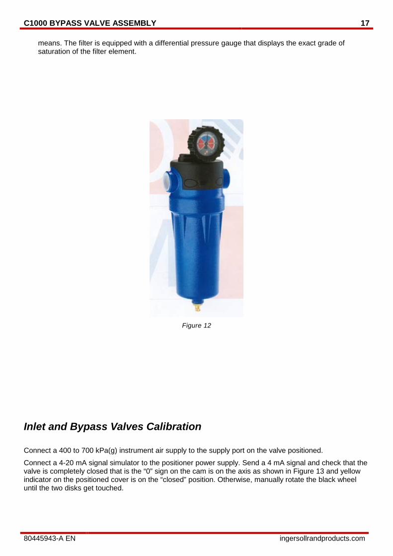
means. The filter is equipped with a differential pressure gauge that displays the exact grade of saturation of the filter element.
Figure 12
Inlet and Bypass Valves Calibration
Connect a 400 to 700 kPa(g) instrument air supply to the supply port on the valve positioned.
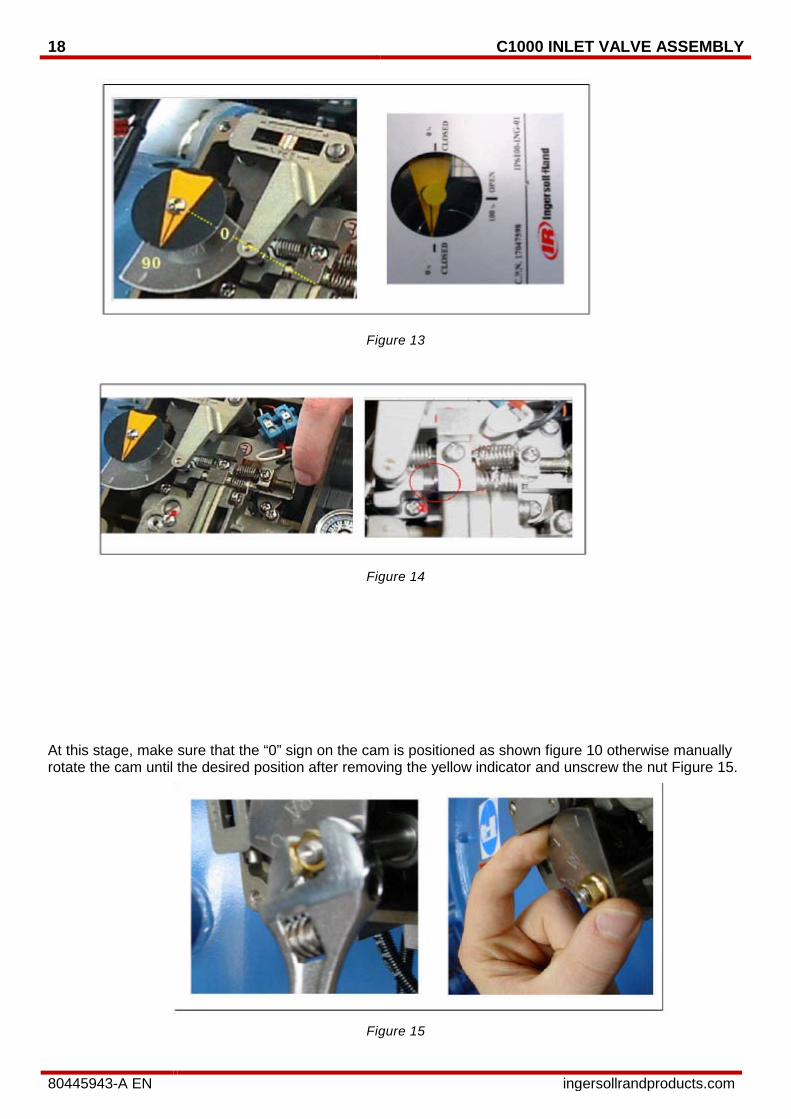
Connect a 4-20 mA signal simulator to the positioner power supply. Send a 4 mA signal and check that the valve is completely closed that is the “0” sign on the cam is on the axis as shown in Figure 13 and yellow indicator on the positioned cover is on the “closed” position. Otherwise, manually rotate the black wheel until the two disks get touched.
18 C1000 INLET VALVE ASSEMBLY
80445943-A EN ingersollrandproducts.com
Figure 13
Figure 14
At this stage, make sure that the “0” sign on the cam is positioned as shown figure 10 otherwise manually rotate the cam until the desired position after removing the yellow indicator and unscrew the nut Figure 15.
Figure 15
C1000 BYPASS VALVE ASSEMBLY 19
80445943-A EN ingersollrandproducts.com
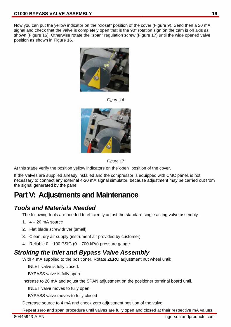
Now you can put the yellow indicator on the “closet” position of the cover (Figure 9). Send then a 20 mA signal and check that the valve is completely open that is the 90° rotation sign on the cam is on axis as shown (Figure 16). Otherwise rotate the “span” regulation screw (Figure 17) until the wide opened valve position as shown in Figure 16.
Figure 16
Figure 17
At this stage verify the position yellow indicators on the”open” position of the cover.
If the Valves are supplied already installed and the compressor is equipped with CMC panel, is not necessary to connect any external 4-20 mA signal simulator, because adjustment may be carried out from the signal generated by the panel.
Part V: Adjustments and Maintenance Tools and Materials Needed
The following tools are needed to efficiently adjust the standard single acting valve assembly.
1. 4 – 20 mA source
2. Flat blade screw driver (small)
3. Clean, dry air supply (instrument air provided by customer)
4. Reliable 0 – 100 PSIG (0 – 700 kPa) pressure gauge
Stroking the Inlet and Bypass Valve Assembly With 4 mA supplied to the positioner. Rotate ZERO adjustment nut wheel until:
INLET valve is fully closed.
BYPASS valve is fully open
Increase to 20 mA and adjust the SPAN adjustment on the positioner terminal board until.
INLET valve moves to fully open
BYPASS valve moves to fully closed
Decrease source to 4 mA and check zero adjustment position of the valve.
Repeat zero and span procedure until valves are fully open and closed at their respective mA values.
20 C1000 INLET VALVE ASSEMBLY
80445943-A EN ingersollrandproducts.com
Routine Maintenance Routine maintenance on the control valve assembly is limited to the following:
• The filters (on the rear of Control Panel) require periodic cleaning and replacement. This period must be established at each compressor site since it is the site air quality that dictates when the cleaning and replacements are required.
• A daily draining of the regulator and coalescing filter will indicate severity of any air contamination problem.
• Checking the calibration (stroking) of the control valves is done, as a matter of routine, in accordance with the compressor Operators Manual on an every six month basis.
Notices and Disclaimers Copyright Notice Copyright 2010 Ingersoll Rand Company.
Proprietary Notices CENTAC is a registered trademark of Ingersoll Rand Company.
This manual contains confidential and trade secret information owned by Ingersoll Rand Company (hereinafter referred to as “Proprietary Matter”). In consideration of the disclosure of the Proprietary Matter herein to the authorized recipient hereof, the recipient shall treat the Proprietary Matter as secret and confidential; shall not disclose or give such Proprietary Matter to third parties without the express written authorization of Ingersoll Rand; shall not use the Proprietary Matter except to the extent necessary to use or service the equipment disclosed herein; and shall disclose such Proprietary Matter only to those of its employees whose use or knowledge of the Proprietary Matter is necessary. This manual shall be returned upon request by Ingersoll Rand Company. The unauthorized use of this manual may be punishable by law.
Disclaimers • This manual and the contents thereof are provided “as is” and without any implied warranties.
• The information in this manual does not relieve operating and maintenance personnel of the responsibility of exercising normal good judgment in operation and care of the compressor and its components.
• The company accepts no responsibility for errors in translation of this manual from the original English version.