C00000-ENG-06-TCN-AAA-0002 - Pre-Commissioning Overview ...€¦ · Doc Title: Pre-Commissioning:...
16
Document Number: C00000-ENG-06-TCN-AAA-0002 C1 18/05/2013 Issued For Use RT KF PD B1 11/03/2013 Issued For Review RT SN A1 11/02/2013 Issued For Comment SN RH Rev No. Rev Date Reason for Issue Prepared Checked Approved Title: Pre-Commissioning Overview: Umbilicals Scale: NTS Size: A4 Lang. EN IMS
Transcript of C00000-ENG-06-TCN-AAA-0002 - Pre-Commissioning Overview ...€¦ · Doc Title: Pre-Commissioning:...

Document Number:
C00000-ENG-06-TCN-AAA-0002
C1 18/05/2013 Issued For Use RT KF PD
B1 11/03/2013 Issued For Review RT SN
A1 11/02/2013 Issued For Comment SN RH
Rev No. Rev Date Reason for Issue Prepared Checked Approved
Title: Pre-Commissioning Overview: Umbilicals
Scale:
NTS
Size:
A4
Lang.
EN IMS

Doc Title: Pre-Commissioning: Umbilicals
Document. No: C00000-ENG-06-TCN-AAA-0002 Rev: C1 Date: 18/05/2013 Page: 2 of 16
REVISION RECORD SHEET
Revision Reason for Change Page Number(s) DCN Number
DISTRIBUTION AND CONTROL STATUS
Document Control Distribution Copy Number
Controlled
Uncontrolled
COPYRIGHT & CONFIDENTIALITY The information contained within this document is provided for the sole use of OFFSHORE ENERGY UK LIMITED personnel, authorised clients and subcontractors. All rights are reserved. No part of this document may be reproduced, stored in a retrieval system or transmitted in any form or by any means, electronic, magnetic tape, mechanical, photocopying, recording or otherwise without permission from OFFSHORE ENERGY UK LIMITED. Printed copies of this document are considered as uncontrolled.
Registered as Offshore Energy UK Limited in England, Company No. 07936973
E [email protected] W www.offshore-energy.co

Doc Title: Pre-Commissioning: Umbilicals
Document. No: C00000-ENG-06-TCN-AAA-0002 Rev: C1 Date: 18/05/2013 Page: 3 of 16
INDEX
1 SCOPE AND PURPOSE 4
2 REFERENCE DOCUMENTS 4
3 DEFINITIONS 4
3.1 PROJECT SPECIFIC TERMS 4 3.2 ABBREVIATIONS 4
4 SUBSEA CONTROL UMBILICAL PRE-COMMISSIONING FAMILIARISATION 6
5 UMBILICAL TYPES 7
5.1 UMBILICAL CROSS SECTION EXAMPLE 9
6 UMBILICAL PRE-COMMISSIONING PRELIMINARY ACTIVITIES 10
6.1 FLUID CLEANLINESS 10 6.2 PRE-LOADOUT TESTING 12 6.3 TRANSPOOLING MONITORING DURING LOADOUT 12 6.4 POST-LOADOUT TESTING 14 6.5 INSTALLATION INTEGRITY MONITORING 14 6.6 FINAL TESTS PRIOR TO OVERBOARDING 15
Doc Title: Pre-Commissioning: Umbilicals
Document. No: C00000-ENG-06-TCN-AAA-0002 Rev: C1 Date: 18/05/2013 Page: 4 of 16
1 SCOPE AND PURPOSE
This document is a reference tool which describes the technical activities and challenges that can be encountered within Umbilical and subsea pre-commissioning projects. Although the information is not exhaustive, it should work as an aid to assist with decisions about seeking technical expertise and guidance. Offshore Energy UK Limited can identify all aspects within pre-commissioning projects to ensure projects are safe, efficient, planned, controlled and managed.
2 REFERENCE DOCUMENTS
Ref Title Document Number
[1] Design and Operation of Subsea Umbilicals, Part 5 ISO 13628-5:2009
[2] Hydraulic fluid power - Calibration of automatic-count instruments for particles suspended in liquids
ISO 4402:1991
[3] Aerospace Fluid Power - Cleanliness Classification for Hydraulic Fluids SAE AS4059E
[4] Aerospace Microscopic Sizing and Counting of Particulate Contamination for Fluid Power Systems
SAE ARP598
3 DEFINITIONS
3.1 PROJECT SPECIFIC TERMS
Term Description
Barg Bar Gauge
3.2 ABBREVIATIONS
Abbreviation Description
BOP Blow Out Preventer
CR DC Resistance
dB Decibel
DC Direct Current
EFLs Electrical Flying Leads
EN English
FAT Factory Acceptance Testing
FPSO Floating Production, Storage And Offloading
HFLs Hydraulic Flying Leads
HV High voltage
IMS Integrated Management System
IR Insulation Resistance
km Kilometre, an SI unit of length
ISO International Organization for Standardization
IWOCS Installation Workover Control Umbilicals

Doc Title: Pre-Commissioning: Umbilicals
Document. No: C00000-ENG-06-TCN-AAA-0002 Rev: C1 Date: 18/05/2013 Page: 5 of 16
LV Low Voltage
MEG Monoethylene Glycol
nm Nanometer, an SI unit of length
NTS Not To Scale
OTDR Optical Time Domain Reflectometry testing
ROV Remotely Operated Vehicle
SCM Subsea Control Modules
SEM Subsea Electronic Module
SPS Subsea Production System
SSIV Subsea Safety Isolation Valve
TDR Time Domain Reflectometry testing
UTA Umbilical Termination Assembly

Doc Title: Pre-Commissioning: Umbilicals
Document. No: C00000-ENG-06-TCN-AAA-0002 Rev: C1 Date: 18/05/2013 Page: 6 of 16
4 SUBSEA CONTROL UMBILICAL PRE-COMMISSIONING FAMILIARISATION
Umbilical pre-commissioning is a suite of tests performed from a host facility, usually an offshore platform or a Floating Production, Storage and Offloading vessel (FPSO), to confirm the mechanical and structural integrity of a newly installed umbilicals and associated infield electrical, hydraulic and (in some instances) fibre optic functional connections. ‘Post hook up’ testing is performed using temporary equipment set up within close proximity of the hang-off location on the host facility in order the minimise the routing of high pressure test hoses, in particular away from walkways and adjacent worksites where possible.
These functional connections are made through the use of dedicated electrical, hydraulic and optical flying leads which allow the conveyance of hydraulic power, communication and production chemicals / service fluids via the umbilicals connected between the host facility and the Subsea Production System.
System design and complexity will ultimately dictate the pre-commissioning testing philosophy and it may prove beneficial to perform sequential testing using a systematic approach, which allows earlier detection and potentially an easier diagnosis of any faults, their type and location.
Pre-commissioning testing is performed in accordance with ISO 13628-5:2009 - Petroleum and Natural Gas Industries — Design and Operation of Subsea Production Systems, Part 5: Subsea Umbilicals. The tests performed during pre-commissioning normally include:
DC resistance testing to confirm electrical continuity of the electric cable conductors present within the main umbilicals and electrical flying leads connected between the host facility and subsea controls equipment, i.e. subsea electronic modules housed within subsea control modules located on the production manifolds and trees.
Insulation resistance testing (IR) to verify the integrity of the cable insulation within each umbilical and electrical flying lead. IR testing also confirms the integrity of the subsea electrical connectors and confirms that each connector / connection is free from water ingress.
Time Domain Reflectometry testing to detect the presence and position of any discontinuities such as kinks, broken conductors and damaged insulation causing low resistance faults within the umbilical cables, and to provide in all cases a 'signature' for each cable which can be compared with earlier tests, i.e. those obtained during factory acceptance testing (FAT). This diagnostic test does not form part of cable test acceptance or rejection criteria.
Optical Time Domain Reflectometry testing (OTDR) to confirm the integrity and routing of each of the optical fibres presented within the umbilical. The OTDR utilises a laser emitting diode to sends short pulses of light down one end of a fibre at a specified wavelength. Light reflected back from a discontinuity that may be presented in or along the fibre and light continuously backscattered from the fibre itself travels back to the OTDR, where the instrument records the optical power being returned and arrival time. The arrival time of the pulse from a given point in the fibre is related to its distance from the OTDR. With this information, the OTDR graphically displays returned power versus distance, known also as attenuation.
Pressure leak testing of the production control low pressure and high pressure supply lines and chemical injection / service lines to 1.0 and 1.1 x design work pressure respectively to confirm the leak tight integrity of both the umbilical(s) and the functional connections downstream of the umbilical, for example between a production manifold and tree.
An overview of the preliminary activities that take place following on from FAT at the umbilical manufacturer’s facility, transportation to the field and installation is discussed later in this document.

Doc Title: Pre-Commissioning: Umbilicals
Document. No: C00000-ENG-06-TCN-AAA-0002 Rev: C1 Date: 18/05/2013 Page: 7 of 16
5 UMBILICAL TYPES
There are numerous suppliers and various types of umbilical for different applications. Umbilicals are manufactured in Europe, North and South America and Asia Pacific regions. Types of umbilicals include:
Production control umbilicals for control, monitoring and delivery of chemicals and hydrate inhibition fluids to manifolds and subsea trees
Water injection umbilicals for control and monitoring of wellhead equipment on water injection systems
Subsea Safety Isolation Valve umbilicals for control, operation and position sensing of valves, and for some systems where requirement exists for monoethylene Glycol injection
Installation Workover Control umbilicals, designed for repeated deployments and used during tree installation and workover operations
Gas lift umbilicals for introduction of optimised amounts of gas to reduce the density of produced fluids and aid field production
Blow Out Preventer umbilicals used to control the wellhead equipment during drilling operations and prevent hydrocarbon blow out in the event of pressure surge from the well
Subsea power umbilicals used for supplying power and controls to subsea processing and multiphase boosting systems. Used for low, medium or high voltage power supply
Submarine power cables used for conveying high voltage power from onshore power production facilities to offshore facilities such as production platforms. May also contain low voltage power / signal and fibre optic transmission cables.
In the case of umbilicals supplied for the offshore oil and gas industry, the construction and design can vary dependant on their function and installation location.
A single main umbilical system can route between two platforms or between a platform and FPSO to single point locations such as a manifold with interconnecting flying leads providing the functional connections to the trees (see Figure 1).
Figure 1: Single umbilical system production cluster arrangement
Dynamic / Static Main Umbilical
Host facility (Platform or FPSO)
Production Manifold
Production Trees
EFL & HFL

Doc Title: Pre-Commissioning: Umbilicals
Document. No: C00000-ENG-06-TCN-AAA-0002 Rev: C1 Date: 18/05/2013 Page: 8 of 16
The length of an umbilical that lies on the seabed is referred to as the static section. The section of umbilical running from the host facility where the pull-in head is located through the water column to the seabed is known as the dynamic section if it is free-hanging regardless if the host facility is a floating system or a fixed system as is the case with a platform.
A multiple main umbilical system could consist of a dynamic / static section of control umbilical installed between a host facility and a production manifold with additional infield ‘static’ umbilicals installed downstream of the first manifold routing to additional manifolds and / or production / water injection trees. A dynamic umbilical suspended from a floating facility is generally subjected to substantial hydrodynamic forces, which a static umbilical avoids due to its sheltered location directly on or beneath the seabed as is the case with a trenched umbilical. Dynamic umbilical suspended from a fix platform are afforded some level of protection from the ‘I’ or ‘J’ tube they are generally installed through.
An example of this field arrangement is shown in Figure 2:
Figure 2: Multiple umbilical subsea production system
The pressure containing elements within umbilicals are generally either thermoplastic hose construction using an aramid yarn single or double pass braiding package dependant on the pressure rating, or super duplex stainless steel tube with varying degrees of wall thickness, again dependant on the pressure rating. Umbilical power / signal cables are generally sized between 2.5-16mm2 and are either twisted copper screened or unscreened pair or quad to suit the majority of non-multiphase subsea production control applications. Fibre optic cabling within subsea control umbilical and production systems is becoming a more common means of providing two-way communications between the host facility and the Subsea Production System. Fibre optic cables have a distinct advantage over copper wire systems with their immunity to electro-magnetic noise interference, wider communication bandwidth, cost and unrepeated communication efficiency over distances in access of 100km.
Dynamic / Static Main Umbilical
Host facility (Platform or FPSO)
Production Manifold
Production Trees
EFL & HFL
Production Manifold
Production Trees
Static Infield Umbilical
Static Infield Umbilical
EFL & HFL
EFL & HFL

Doc Title: Pre-Commissioning: Umbilicals
Document. No: C00000-ENG-06-TCN-AAA-0002 Rev: C1 Date: 18/05/2013 Page: 9 of 16
5.1 UMBILICAL CROSS SECTION EXAMPLE
Figure 3 presents an example of a submarine multiphase power and control umbilical used to convey high voltage electrical power, hydraulic power and communications to a subsea separation unit:

Doc Title: Pre-Commissioning: Umbilicals
Document. No: C00000-ENG-06-TCN-AAA-0002 Rev: C1 Date: 18/05/2013 Page: 10 of 16
6 UMBILICAL PRE-COMMISSIONING PRELIMINARY ACTIVITIES
Various monitoring and testing activities are required to be performed at various stages following FAT; for example, during load out operations at the manufacturer’s facility, post load out prior to shipping, during transportation, and during umbilical pull-in and lay operations from the installation vessel. The sections below provide overviews of the monitoring and testing activities for subsea control umbilicals required at each of the stages. All tests should be performed in accordance with ISO 13628-5:2009 and in strict compliance with the manufacturer’s written guidelines.
6.1 FLUID CLEANLINESS
The control and chemical injection hoses / tubes, whichever are applicable within an umbilical, are flushed during FAT to the required cleanliness standard. This is generally SAE AS 4059E Class 6 (b-f) for the controls tubing and Class 8 (b-f) for the chemical / service line tubing. A clean hydraulic system is of critical importance because contaminated fluid under pressure causes accelerated wear and reduces life of components within hydraulic systems. The replacement of worn parts on subsea production systems, for example a subsea control module, is extremely expensive due to the specialised equipment and type of vessel required to complete remedial works and significant replacement costs of a subsea control module. For these reasons it is of equal importance that any temporary equipment and fluids being used to facilitate hydraulic testing of an umbilical are pre-flushed and certified clean to the same standard prior to being connected for testing purposes. Various instruments and methods can be used for sampling and assessing fluid cleanliness in accordance with the relevant industry standard. The industry’s preferred method for assessing fluid cleanliness is to use a microscope with varying degree of magnification to assess the level and type of contamination present within a 100ml fluid sample. The recognised standard for performing such assessments is SAE ARP598 Rev C - Aerospace Microscopic Sizing and Counting of Particulate Contamination for Fluid Power Systems. Various types of contamination can be found when performing a cleanliness assessment. Typical examples include:
Silica: Hard, translucent particles often associated with atmospheric and environmental contamination
Bright metal: Shiny metallic particles, usually silver or gold in colour, generated in systems from mechanical wear and cause additional component wear and accelerated fluid breakdown
Black metal: Oxidised ferrous metal, not commonly seen in umbilical fluids due to the use of 25cr super duplex tubing

Doc Title: Pre-Commissioning: Umbilicals
Document. No: C00000-ENG-06-TCN-AAA-0002 Rev: C1 Date: 18/05/2013 Page: 11 of 16
During initial set up and pre-flushing of test fluids, three fluid samples are obtained from each pumping system to verify fluid cleanliness to the required standard. The industry-recommended practice is for samples to be obtained at 15 minute intervals until three consecutive samples better than the specified cleanliness class for acceptance are obtained. This is to ensure that the samples are seen to be representative of the system and not a single “rogue” clean or dirty sample. The size and number of particles per 100ml of fluid determines the overall cleanliness classification in accordance with the Table 2 provided in SAE AS 4059 E (see Figure 4).
(1) >1µm >5µm >15µm >25µm >50µm >100µm
(2) >4µm(c) >6µm(c) >14µm(c) >21µm(c) >38µm(c) >70µm(c)
Size code classes
A B C D E F
000 195 76 14 3 1 0
00 390 152 27 5 1 0
0 780 304 54 10 2 0
1 1560 609 109 20 4 1
2 3120 1217 217 39 7 1
3 6250 2432 432 76 13 2
4 12500 4864 864 152 26 4
5 25000 9731 1731 306 53 8
6 50000 19462 3462 612 106 16
7 100000 38924 6924 1224 212 32
8 200000 77849 13849 2449 424 64
9 400000 155698 27698 4898 848 128
10 800000 311396 55396 9796 1696 256
11 1600000 622792 110792 19592 3392 512
12 3200000 1245584 221584 39184 6784 1024
Figure 4: SAE AS4059 E Table 2 (cleanliness classes for cumulative counts) particles per 100ml
(1) Size range, optical microscope, based on longest dimension as measured per ARP598 or APC Calibrated per ISO 4402:1991.
(2) Size range, APC Calibrated per ISO 11171 or electron microscope, based on projected area
equivalent diameter.
Fibres: Contaminants most commonly generated from paper and fabrics, coveralls, etc.

Doc Title: Pre-Commissioning: Umbilicals
Document. No: C00000-ENG-06-TCN-AAA-0002 Rev: C1 Date: 18/05/2013 Page: 12 of 16
6.2 PRE-LOADOUT TESTING
Pre-loadout testing is a required if the umbilicals have been stored at the manufacturer’s facility for a period exceeding three months prior to loadout, regardless of whether the umbilical in question is to be transpooled from an onshore based carousel to a vessel based carousel or be transferred in a single lift, i.e. on an installation reel.
The following tests are required to be performed dependant on umbilical design to verify the integrity of the umbilicals prior to loadout:
DC resistance testing (CR) to confirm the integrity of the cable conductors within each umbilical
Insulation resistance testing (IR) to confirm cable insulation integrity
Time Domain Reflectometry testing in the event of an unexplainable CR and / or IR fault
Where fibre optic cables are present, Optical Time Domain Reflectometry (OTDR) testing to obtain attenuation dB / km values for comparison with FAT values to confirm fibre optic cable integrity. If possible testing should be performed from both ends of the umbilicals.
Hydraulic pressure leak testing to verify hose / tube integrity. Testing at pre-loadout stage should be performed at 1.1 x umbilical design pressure with a hold period of four hours. Umbilical tubes should be manifolded together by fluid type and pressure rating. Figure 5 shows a typical set up:
Figure 5: Pre-loadout testing typical set up
6.3 TRANSPOOLING MONITORING DURING LOADOUT
Loadout operations are controlled and supervised by the umbilical Installation Contractor. The nominated supervisor for the loadout operations will hold a meeting to ensure all personnel involved in the operation are aware of the procedures being adopted, how communications will be co-ordinated and the timetable for the loadout. Particular emphasis will be placed on safety and the steps to be undertaken in the event of an unforeseen event occurring which has or could compromise the safety of personnel or damage to equipment. Prior to commencing the loadout operation, it is important to ensure the validity of any certification required for equipment being used to lift, transpool or monitor at any stage of the operation, is inspected and verified as being current. Function testing of equipment required for monitoring the integrity of the umbilical during loadout should be completed at this stage and the connection of the equipment to the umbilical witnessed to ensure no cross contamination of fluids or connection of high pressure equipment to low pressure tubing has taken place.
Doc Title: Pre-Commissioning: Umbilicals
Document. No: C00000-ENG-06-TCN-AAA-0002 Rev: C1 Date: 18/05/2013 Page: 13 of 16
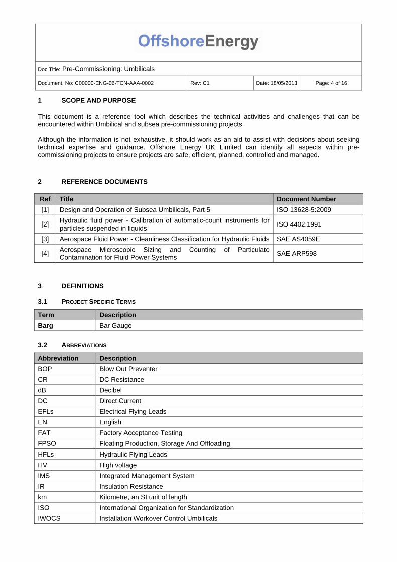
Once these preliminary activities have been completed the load out operation may commence. Figure 6 shows a first end umbilical termination assembly (UTA) transfer:
Figure 6: UTA transfer shore to vessel
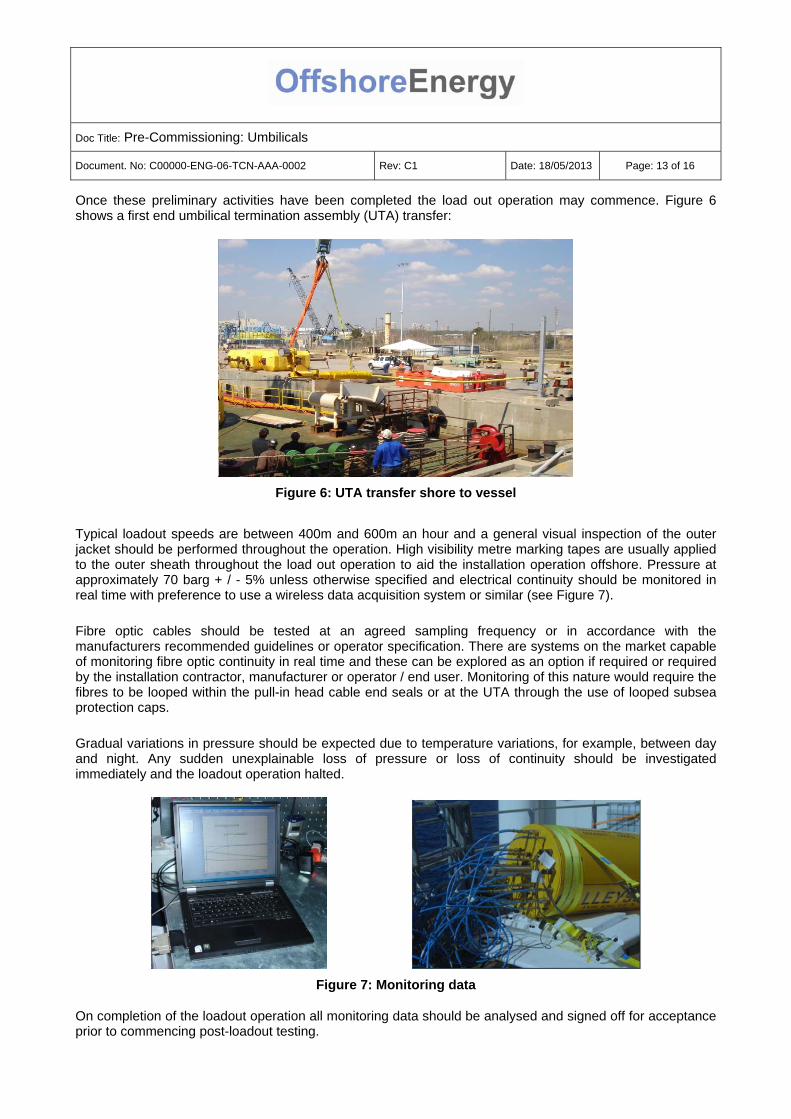
Typical loadout speeds are between 400m and 600m an hour and a general visual inspection of the outer jacket should be performed throughout the operation. High visibility metre marking tapes are usually applied to the outer sheath throughout the load out operation to aid the installation operation offshore. Pressure at approximately 70 barg + / - 5% unless otherwise specified and electrical continuity should be monitored in real time with preference to use a wireless data acquisition system or similar (see Figure 7). Fibre optic cables should be tested at an agreed sampling frequency or in accordance with the manufacturers recommended guidelines or operator specification. There are systems on the market capable of monitoring fibre optic continuity in real time and these can be explored as an option if required or required by the installation contractor, manufacturer or operator / end user. Monitoring of this nature would require the fibres to be looped within the pull-in head cable end seals or at the UTA through the use of looped subsea protection caps. Gradual variations in pressure should be expected due to temperature variations, for example, between day and night. Any sudden unexplainable loss of pressure or loss of continuity should be investigated immediately and the loadout operation halted.
Figure 7: Monitoring data
On completion of the loadout operation all monitoring data should be analysed and signed off for acceptance prior to commencing post-loadout testing.

Doc Title: Pre-Commissioning: Umbilicals
Document. No: C00000-ENG-06-TCN-AAA-0002 Rev: C1 Date: 18/05/2013 Page: 14 of 16
6.4 POST-LOADOUT TESTING
Post-loadout testing is performed to verify the umbilical has not sustained any damage to the internal components during transpooling activities. This damage may not have manifested at loadout pressure, which is significantly less than umbilical design pressure. Likewise, electrical continuity monitoring verifies conductor condition but is not an indicator of cable insulation condition; therefore, a series of insulation resistance tests are performed for each cable to verify insulation condition. If fibre optic cabling is present it should be subjected to an OTDR test to verify attenuation values are within the acceptance criteria specified by manufacturer’s written specification. Testing for Singlemode fibre is generally performed using two wavelengths, 1310 and 1550 nanometres (nm), with attenuation values dependant on the specification of the fibre generally between 0.18 and 2.0 dB / km at 1550nm. Where possible, testing should be performed from both ends of the umbilical to verify the absence of any potential breaks in the fibres very close to the remote end of the cable being tested.
6.5 INSTALLATION INTEGRITY MONITORING
Installation lay monitoring generally commences the moment the first end UTA leaves the installation reel or vessel carousel. The parameters to be continuously monitored in real time include:
Visual inspection for external damage to umbilical sheath
Electrical continuity for each pair of looped conductors recorded using a wireless data acquisition system. If there is any loss or sudden change of continuity, the operation should be halted and a DC-conductor resistance test on the individual cables using a precision ohmmeter or similar.
Note: Subsea looped protection caps (see Figure 8) which provide short circuits are utilised where the first end overboard is a UTA. Where the first end overboard is a pull-in head, the cables are stripped and conductors crimped together by common pair prior to installing water blocking cable end seals. This operation is usually completed in the factory, but in some instances these caps are installed offshore, in particular where the pull-in head is the final end to go overboard.
Figure 8: Subsea electrical protection caps
A wireless data transmission and acquisition system with a calibrated pressure transducer connected to each monitoring manifold is the most practical way of monitoring and recording

Doc Title: Pre-Commissioning: Umbilicals
Document. No: C00000-ENG-06-TCN-AAA-0002 Rev: C1 Date: 18/05/2013 Page: 15 of 16
pressure throughout the installation. Pressure should be monitored, recorded and maintained within an approved pressure window as agreed between the Installation Contractor and manufacturer in accordance with operator / end user specification.
Typically, a minimum pressure of 70 barg is used; however, to provide a longer lay parameter for the Installation Contractor, in some instances a bottom limit of 40 barg and top limit of 100 barg or higher is used. If there is any unexplainable loss of pressure or if the behaviour of one hose / tube group relative to others is markedly different, the operation should be halted and the cause of the pressure loss investigated. The requirement for pressure compensation during umbilical installation is driven by the change in temperature the product goes through from above surface ambient conditions to static conditions on the sea bed. The rule of thumb is that temperature change effect versus pressure typically results in a pressure drop or increase equivalent to approximately 10 bars per °C change in temperature. For this reason, significantly more fluid is required where umbilicals are installed in warmer regions due to greater difference in above surface ambient temperature compared to the sea bed. The time of year and the anticipated temperature variations likely to be encountered should be considered during detailed engineering to ensure sufficient quantity of fluid is provided for pressure compensation activities. Particular focus should be given to short length infield umbilicals being installed in deep water where in some instances the second end UTA leaves the vessel before the first end UTA reaches the seabed. Significant pressure may need to be added prior to the second end UTA leaving the vessel to ensure an above ambient pressure within the umbilical, to prevent seawater ingress through multi quick connector poppet valves post installation, i.e. once the umbilical has been installed and is in a static condition prior to hook up. In some instances, installation of subsea pressure monitoring equipment to the second end UTA for pressure verification during deployment may be required.
6.6 FINAL TESTS PRIOR TO OVERBOARDING
A series of final tests are required prior to overboarding the second end UTA. Prior to disconnecting the pressure monitoring equipment, the pressure data should be reviewed for acceptance before pressure within each group of umbilical tubes is adjusted to an approved overboarding pressure. The wireless monitoring equipment used for monitoring and recording conductor resistance should be disconnected in parallel with the pressure monitoring equipment in preparation for final electrical, and if applicable, fibre optic cable OTDR testing (see Figure 9).
DC resistance testing (CR) to confirm the integrity of the cable conductors within each umbilical
Insulation resistance testing (IR) to confirm cable insulation integrity
Time Domain Reflectometry testing (TDR) in the event of an unexplainable CR and / or IR fault
Where fibre optic cables are present, Optical Time Domain Reflectometry testing (OTDR) to obtain attenuation dB / km values for comparison with FAT values to confirm fibre optic cable integrity.

Doc Title: Pre-Commissioning: Umbilicals
Document. No: C00000-ENG-06-TCN-AAA-0002 Rev: C1 Date: 18/05/2013 Page: 16 of 16
Figure 9: Pre-second end UTA overboarding testing
Following completion of umbilical installation, the hook up of the functional connections may take place. The design of some vertical and horizontally connected umbilical termination units negates the requirement for hydraulic flying leads to be used as a functional connection between the umbilical and, for example, a production manifold. The hydraulic connection in this instance is made directly when the termination is brought into its final position to the inboard hub on the manifold using a deployment frame and remotely operated vehicle (ROV) actuated stroking tool to make the connection through the use of, for example, a collet-type umbilical connector. In this instance, the post-installation test becomes a post-hook up test, or commencement of pre-commissioning, with the hydraulic connection being testing either intermediately, i.e. against closed isolation valves in the manifold or, for example, in parallel with any hydraulic functional connections that may have been made between the manifold and production tree.