C. Rossi – L4 Project Meeting 3 March 2011 Status and Plans of 3 MeV Test Stand.
15
Rossi – L4 Project Meeting 3 March 2011 Status and Plans of 3 MeV Test Stand
-
Upload
lauren-dabbs -
Category
Documents
-
view
214 -
download
1
Transcript of C. Rossi – L4 Project Meeting 3 March 2011 Status and Plans of 3 MeV Test Stand.

C. Rossi – L4 Project Meeting 3 March 2011
Status and Plans of3 MeV Test Stand

C. Rossi – L4 Project Meeting 3 March 2011
The 3 MeV Test Stand is installed in the PS South Hall extension (building 152)
C. Rossi – L4 Project Meeting 3 March 2011
Activities at the Test Stand in 2010Source Operation
Impossible to operate the ion source with H- at 45 kV extraction voltage
Characterize the source for p extraction at 45 kV to allow RFQ and partial MEBT commissioning

C. Rossi – L4 Project Meeting 3 March 2011
Activities at the Test Stand in 2010Source Results with protons
0 200 400 600 800 1000 12000
5
10
15
20
25
30
35
40
f(x) = 0.034941351888668 x + 2.70412524850895
Simulated Beam Size @ the SEM vs Espread
Input Energy spread (ev)
Beam
siz
e at
SEM
(mm
)
Slit : 1mmSol : 600 A
10 12 14 16 18 20 22 24 26 28 300
5
10
15
20
25
30
35
Spectrometer current [A]
Fara
day
cup
curr
ent
[mA
]
20 25 30 35 40 45 50 55 6005
10152025303540
RF-power [kW]
Fara
day
cup
curr
ent
[mA
]
The energy spread of the beam is not larger than 400 eV (50 eV per mm) => ± 200 eV => ± 0.4 %
Pictures from O. Midttun’s presentation
Slit 1 mmSol 600 A
C. Rossi – L4 Project Meeting 3 March 2011
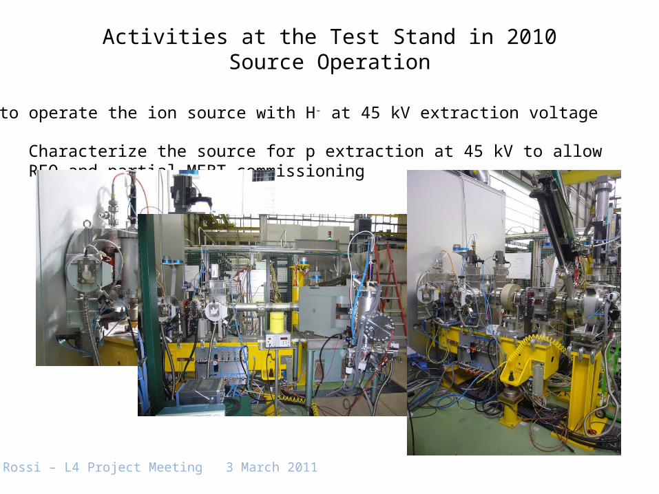
Activities at the Test Stand in 2010MEBT line completed
With 3rd buncher cavity

C. Rossi – L4 Project Meeting 3 March 2011
Activities at the Test Stand in 2010RF installation progress
2nd buncher amplifier installed

C. Rossi – L4 Project Meeting 3 March 2011
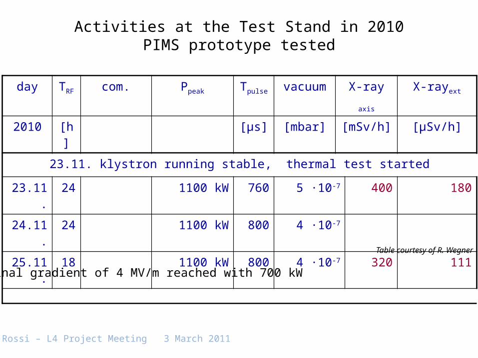
Activities at the Test Stand in 2010PIMS prototype tested
C. Rossi – L4 Project Meeting 3 March 2011
Activities at the Test Stand in 2010PIMS prototype tested
day TRF com. Ppeak Tpulse vacuum X-ray axis X-rayext
2010 [h] [μs] [mbar] [mSv/h] [μSv/h]
23.11. klystron running stable, thermal test started
23.11. 24 1100 kW 760 5 ·10-7 400 180
24.11. 24 1100 kW 800 4 ·10-7
25.11. 18 1100 kW 800 4 ·10-7 320 111
Nominal gradient of 4 MV/m reached with 700 kW
Table courtesy of R. Wegner

C. Rossi – L4 Project Meeting 3 March 2011
Activities related to the Test Stand in 2010Movable Test Bench
Design of Test Bench completed;Design of all components completed;Fabrication started for all components;Start of assembly in May.

C. Rossi – L4 Project Meeting 3 March 2011
Characterize the beam properties at 3 MeV:
•At the RFQ exit in the Linac4 Test Stand (late 2011 and beginning of 2012)•At the chopper line output in the Linac4 Test Stand (during 2012)
•At the chopper line output in the Linac4 Tunnel (early 2013)
Characterize the beam properties at 12 MeV:
•At the DTL tank1 output in the Linac4 Tunnel (first half 2013)
Transverse plane Longitudinal plane
Beam profiles Beam emittances Beam position Transverse halo
Transmission Average beam energy Energy spread Bunch shape profile Chopping efficiency (time resolved and integrated)
From: G. Bellodi - User Specification for Linac4 Test Bench Diagnostics
Activities related to the Test Stand in 2010Movable Test Bench
C. Rossi – L4 Project Meeting 3 March 2011
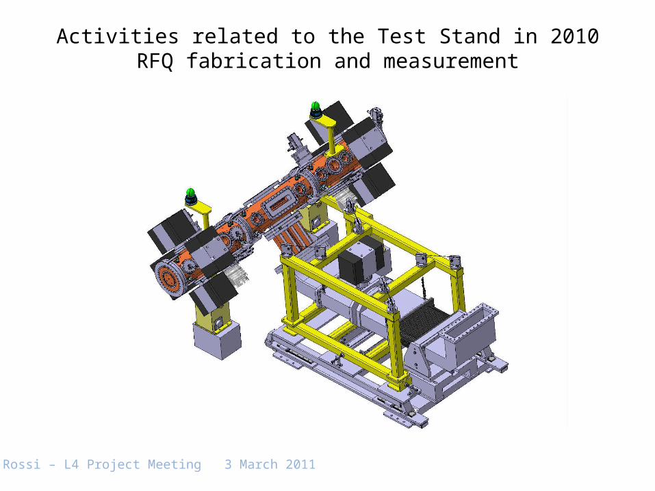
Activities related to the Test Stand in 2010RFQ fabrication and measurement

C. Rossi – L4 Project Meeting 3 March 2011
Module 1 completely brazed, final machining still to be performed:
Activities related to the Test Stand in 2010RFQ fabrication and measurement

C. Rossi – L4 Project Meeting 3 March 2011
Module 3 passed 1st brazing, now is being machined for 2nd brazing.
Activities related to the Test Stand in 2010RFQ fabrication and measurement

C. Rossi – L4 Project Meeting 3 March 2011
Planning to RFQ completion
Activities related to the Test Stand in 2010RFQ fabrication and measurement
RF measurement step week
T2 after assembly 14-15 (2/04)
T2 after 1st brazing 19-20 (9/05)
T3 after 2nd brazing 19-20 (9/05)
T2 after 2nd brazing 29-30 (18/07)
RFQ assembly 35-36 (1/09)
Fittings (tuners, power coupler, end plates) tbd
RFQ completely assembled as from 44 (31/10)

C. Rossi – L4 Project Meeting 3 March 2011
• Continue measurements and development of the ion source;
• Complete the infrastructure for the RFQ and Movable Test Bench installation (cabling, cooling);
• Perform the interlock system installation;
• Assemble the Movable Test Bench;
• Complete equipment installation (buncher amplifier(s), LLRF equipment, beam diagnostics, power supplies);
• Equip the control room;
• Perform the RFQ final tuning;
• Perform the RFQ RF commissioning.
The Test Stand equipment will be moved to Linac4 at the beginning of 2013.
Activities at the Test Stand in 2011