C O N T E N T S - uspowerco.com · DOOSAN - MAN DIESEL. Group. A. GENERAL SPECIFICATION. Group. B....
19
L16/24, L21/31, L27/38 DOOSAN - MAN DIESEL Group A GENERAL SPECIFICATION Group B TEST & MEASUREMENT AT SHOP Group C FOUNDATION, DAMPING, PIPING Group D FUEL OIL SYSTEM Group E LUB. OIL SYSTEM Group F COOLING WATER SYSTEM Group G COMPRESSED AIR SYSTEM Group H COMBUSTION AIR/EXHAUST GAS SYSTEM Group I SPEED CONTROL SYSTEM Group J SAFETY/CONTROL/MONISTORING SYSTEM Group K STARTER PANEL Group L SPARE PARTS & TOOLS Group M ALTERNATOR & MISCELLANEOUS □ : DOOSAN's Standard ◇ : Alternative Standard ○ : Optional Item B : Built-on engine L : Separately delivered C O N T E N T S S Y M B O L M A R K 2 / 19
Transcript of C O N T E N T S - uspowerco.com · DOOSAN - MAN DIESEL. Group. A. GENERAL SPECIFICATION. Group. B....
L16/24, L21/31, L27/38DOOSAN - MAN DIESEL
Group A GENERAL SPECIFICATION
Group B TEST & MEASUREMENT AT SHOP
Group C FOUNDATION, DAMPING, PIPING
Group D FUEL OIL SYSTEM
Group E LUB. OIL SYSTEM
Group F COOLING WATER SYSTEM
Group G COMPRESSED AIR SYSTEM
Group H COMBUSTION AIR/EXHAUST GAS SYSTEM
Group I SPEED CONTROL SYSTEM
Group J SAFETY/CONTROL/MONISTORING SYSTEM
Group K STARTER PANEL
Group L SPARE PARTS & TOOLS
Group M ALTERNATOR & MISCELLANEOUS
□ : DOOSAN's Standard
◇ : Alternative Standard
○ : Optional Item
B : Built-on engine
L : Separately delivered
C O N T E N T S
S Y M B O L M A R K
2 / 19

L16/24, L21/31, L27/38DOOSAN - MAN DIESELNo. Items Remark
A01 Client
A02 Plant Type
A03 Plant Owner
A04 Total quantity of Plant
A05 Number of Genset
A06 Type of application ■ Base load ◇ Peak load
A07 NOx Classification ○
A08 Blank
A09 Noise regulation ■ IMO resolution A.468 (XII)
A10 Performance of engine
1) Model
2) Speed
3) Power output at engine See note
4) Power output at alternator
5) S.F.O.C. See note
N o t e
A10
- Compressor inlet pressure : 1,000mbar
- Ambient air pressure : 1,000mbar
is recommended.
5) With engine driven [LO, HT, LT] pumps at [100%] MCR.
- Charge air coolant temperature : 36℃
5) Viscosity of distillate fuel oil at engine inlet is min. 2cSt, but min. 3cSt with safety margine
3) The power outputs(100% MCR) remain valid up to tropical condition at sea level, i.e.
Ten (10)
1,000 rpm
9L21/31
Specifications
5) Five(5)% tolerance shall be considered.
5) For operation with MGO, SFOC will be increased by 2.0 g/kWh.
1,980 kW
Group A GENERAL SPECIFICATION
Type 1
1,881 kWe
202.0 g/kWh
- Ambient air temperature : 25℃
- Cooling water temperature : 25℃(upstream of charger air cooler)
- Compressor inlet temperature : 40℃
5) The stated consumption figure refers to the following ISO reference conditions :
- Lower calorific value of fuel oil : 42,700kJ/kg
3 / 19
L16/24, L21/31, L27/38DOOSAN - MAN DIESELNo. Items RemarkSpecifications
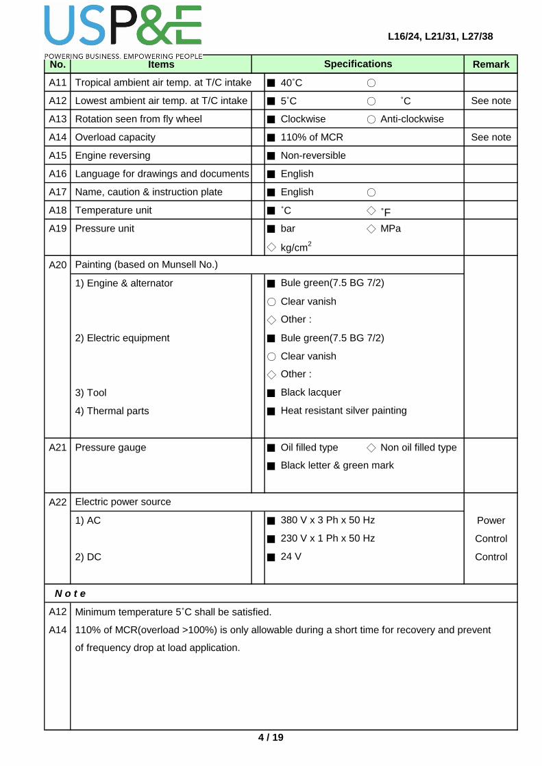
A11 Tropical ambient air temp. at T/C intake ■ 40˚C ○
A12 Lowest ambient air temp. at T/C intake ■ 5˚C ○ ˚C See note
A13 Rotation seen from fly wheel ■ Clockwise ○ Anti-clockwise
A14 Overload capacity ■ 110% of MCR See note
A15 Engine reversing ■ Non-reversible
A16 Language for drawings and documents ■ English
A17 Name, caution & instruction plate ■ English ○
A18 Temperature unit ■ ˚C ◇ ˚F
A19 Pressure unit ■ bar ◇ MPa
◇ kg/cm2
A20
1) Engine & alternator ■
○ Clear vanish
◇
2) Electric equipment ■ Bule green(7.5 BG 7/2)
○ Clear vanish
◇
3) Tool ■
4) Thermal parts ■
A21 Pressure gauge ■ Oil filled type ◇ Non oil filled type
■
A22
1) AC ■ Power
■ Control
2) DC ■ Control
N o t e
A12 Minimum temperature 5˚C shall be satisfied.
A14 110% of MCR(overload >100%) is only allowable during a short time for recovery and prevent
Other :
24 V
Electric power source
Black letter & green mark
Other :
230 V x 1 Ph x 50 Hz
Heat resistant silver painting
Black lacquer
of frequency drop at load application.
380 V x 3 Ph x 50 Hz
Painting (based on Munsell No.)
Bule green(7.5 BG 7/2)
4 / 19
L16/24, L21/31, L27/38DOOSAN - MAN DIESELNo. Items RemarkSpecifications
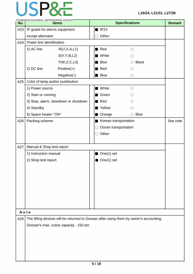
A23 IP grade for elecric equipment ■ IP23
except alternator ○ Other:
A24
1) AC line R(U,X,A,L1) ■ Red ◇
S(V,Y,B,L2) ■ White ◇
T(W,Z,C,L3) ■ Blue ◇ Black
2) DC line Positive(+) ■ Red ◇
Negative(-) ■ Blue ◇
A25
1) Power source ■ White ◇
2) Start or running ■ Green ◇
3) Stop, alarm, slowdown or shutdown ■ Red ◇
4) Standby ■ Yellow ◇
5) Space heater "ON" ■ Orange ◇ Blue
A26 Packing scheme ■ See note
○
○
A27
1) Instruction manual ■ One(1) set
2) Shop test report ● One(1) set
N o t e
A26
Color of lamp and/or pushbutton
Ocean transportation
The lifting devices will be returned to Doosan after using them by owner's accounting.
Power line identification
Other:
Manual & Shop test report
Doosan's max. crane capacity : 150 ton
Korean transportation
5 / 19

L16/24, L21/31, L27/38DOOSAN - MAN DIESELNo. Items RemarkSpecifications
B01
1) 10% load ○ 0.5 hr ○ 1.0 hr
2) 25% load ○ 0.5 hr ○ 1.0 hr
3) 50% load ○ 0.5 hr ○ 1.0 hr
4) 75% load ○ 0.5 hr ○ 1.0 hr
5) 100% load ○ 1.0 hr ○ 1.0 hr
6) 110% load ○ 0.5 hr ○ 1.0 hr
7) Specified ( %) load ○ 0.5 hr
8) Other ○
○
○
○
○
○ Turning gear blocking device test
○
B02
1) Crankshaft deflection ■ Without
○ Cold condition ○ Hot condition
2) Bearing temperature ■ Without ○ One eng./plant See note
○ Each engine
3) Mechanical vibration at MCR ■ Without ○ One eng./plant
○ Each engine
4) Torsional vibration ■ Without ○ One eng./plant
○ Each engine
5) Noise level ■ Without ○ One eng./plant See note
○ Each engine
6) F.O. consumption at each load ■ Without ○ With
7) Other: ○
N o t e
B02 2) Temperature of a main bearing & a crank pin bearing will be checked after test running.
Load test ; The simple operation test will be performed according to Doosan's standard
Group B TEST & MEASUREMENT AT SHOP
Starting, stop test
Shutdown test (safety test)
Load characteristic test
Measurement
Governor test
Parallel running test
Additional test:
5) Measured figures shall be considered as "for reference only".
6 / 19

L16/24, L21/31, L27/38DOOSAN - MAN DIESELNo. Items RemarkSpecifications
B03 NOx emission test ■
○ With
B04 Overhaul inspection ○
○
○ C/S journal ○ Crank pin bearing
○ Main bearing ○ Cyl. liner
○ Cyl. cover ○ Connecting rod
○ Piston ○ Camshaft
○
B05 Calculation ■
○
N o t e
Two(2) cylinders/each engine
One(1) cylinder/each engine
Without
Additional inspection :
Torsional vibration for genset
Additional calculation:
7 / 19

L16/24, L21/31, L27/38DOOSAN - MAN DIESELNo. Items RemarkSpecifications
C01 Common bed(base frame) ■ With
with resilient rubber mountings
C02 Jack bolts for leveling ■ With
C03 Type of coupling between B □
engine & alternator B ○
B ■
C04 Damping device B ■
C05 Gangway B ■
□
C06 External flanges B ■
L ○
C07 Turning device for flywheel B ■ See note
B ○
B ○
C08 Connection between eng. and plant ○
○
○
○
○
C09 Protection cover for flywheel ■ With
N o t e
C07
DIN standard
Group C FOUNDATION, DAMPING, PIPING
Flexible coupling
Direct disc coupling
Drilled counter flanges, gaskets and bolts
Torsional vibration damper
Flexible coupling for 8,9L21/31 & 8,9L27/38
Hand rail and vertical ladder for L21/31 & L27/38
Without for L16/24
Sealed
ISO standard
Flexible connecting hose including
for L21/31 & L27/38
Manual gear
Air turning device for L21/31 & L27/38
Other:
KS/JIS standard
Electric driven with control device
expansion joint after T/C
Air turning device & Electric driven are not available for L16/24.
8 / 19

L16/24, L21/31, L27/38DOOSAN - MAN DIESELNo. Items RemarkSpecifications
D01 Fuel oil according to ISO 8217-2010 ■
and CIMAC-2003 ◆ See note
D02 Insulation on fuel oil pipe ■
◇
D03 Heat tracing on fuel oil in/outlet pipe ■
B ○
○
D04 Fuel injection equipment B ■
B ■
B ■
D05 Leakage alarm box for waste oil B ■ With
(LAH42)
D06 Fuel oil duplex filter B ■ Without
L ○ With (25 microns abs.)
D07 Emergency MDO/GO pump unit ■ Without
L ○ With : 1 eng. 100% operation See note
L ○ With : eng. % operation See note
N o t e
D01
D07
Group D FUEL OIL SYSTEM
HFO(Max. 700cSt at 50℃)
Steam
Pump with air motor, solenoid valve, air conditioning unit, simplex suction filter.
is recommended.
Without
Fuel injection pump on each cylinder
Fuel injection valve on each cylinder
Double-walled high pressure
MDO & MGO
Without, for MDO & MGO operation
injection pipe on each cylinder
Viscosity of distillate fuel oil at engine inlet is min. 2cSt, but min. 3 cSt with safety margine
With, for HFO operation
Other:
9 / 19

L16/24, L21/31, L27/38DOOSAN - MAN DIESELNo. Items RemarkSpecifications
D08 HFO/DO 3-way ball valve ■ Without ○ With
1) Type L ○ per eng.
L ○ per eng.
2) Common valve control box ■ Without
L ○ With per eng.
3) Valve flange size L ○
○
D10 Pressure control valve on ■ Without
external system L ○
L ○
L ○
N o t e
including solenoid valve & limit switches
Other:
Pressure regulating v/v on MDO outlet
Same as engine inlet/outlet pipe
Pressure regulating v/v on HFO inlet
: One(1) set/plant, 8 bar / DN
: One(1) set/plant, 2 bar / DN
Pressure regulating v/v on MDO inlet
: One(1) set/plant, 5 bar / DN
Manually operated two(2) sets including
Pneumatically activated two(2) sets
limit switches
10 / 19

L16/24, L21/31, L27/38DOOSAN - MAN DIESELNo. Items RemarkSpecifications
E01 Lub. oil viscosity ■ SAE 40
E02 Lub. oil pump B ■
E03 Oil sump in engine B ■ Wet type including level switches
(LAL/LAH28)
E04 Lub. oil cooler B ■
water cooling
E05 Pre-lubricating pump B ■
E06
1) Duplex full-flow filter with paper B ■ With
cartridges : Manual type
2) Centrifugal by-pass filter B ■ Without ○ With
: Glacier type
3) Automatic filter B ■ Without ○ With
Only for L21/31 and L27/38
E07 Lub. oil temperature control valve B ■
E08 Connection for external system B ■
B ○
N o t e
Electric-driven(gear type, oil seal)
Voltage : 380V, 50Hz
Lub. oil filter
Thermostatic 3-way valve(wax type)
For overflow cleaning with flexible hose
For purifier(or separator)
Group E LUB. OIL SYSTEM
Engine-driven lub. oil pump
(gear type, oil seal)
Stainless steel plate for fresh
11 / 19

L16/24, L21/31, L27/38DOOSAN - MAN DIESELNo. Items RemarkSpecifications
F01
1) HT circuit ■ Fresh water
2) LT circuit ■ Fresh water See note
F02 Internal cooling circuit □ One string ● Two string
F03 Engine-driven pump ■ See note
F04 Thermostatic valve(wax type) ■
F05 Pre-heating unit for HT cooling circuit
1) Hot water from engine in operation B ■ With See note
via venting connection(F3 connection)
2) HT FW from preheater inlet B ■ Without ○ With
(F6 connection)
F06 External pre-heating unit L ■ Without ○ With
1) External pre-heater module Q'ty ○ One unit/engine
2) External pre-heater type ○ Electric ○ Steam
3) Pump Q'ty ○ One(1)/unit ○ Two(2)/unit
F07 Internal pre-heating unit B ■ Without ○ With
N o t e
F01
F03
F05
is advised that the air vent piping to be arranged with multi-engines common connection
and installed an orifice in common line.
Group F COOLING WATER SYSTEM
Cooling medium
HT & LT cooling circuit
HT & LT water pump
1) For ensuring hot water flow from engine(s) in operation to stand-by engine(s), the client
Cooling water inlet temperature will be max. 46°C for fresh water.
Centrifugal type and mechanical seal.
12 / 19

L16/24, L21/31, L27/38DOOSAN - MAN DIESELNo. Items RemarkSpecifications
F08
1) Pipe size of HT and/or LT ■ Without ○ DN80
○ DN ○
2) Pipe size of pre-heating ■ Without ○ DN25
interconnection ○ DN15 ○
3) LT inlet (one set/eng.) L ■ Without ○ With(Loose)
4) LT outlet (one set/eng.) L ■ Without ○ With(Loose) See note
5) HT inlet (one set/eng.) L ■ Without ○ With(Loose) See note
6) HT outlet (one set/eng.) L ■ Without ○ With(Loose)
7) Preheating interconnection L ■ Without ○ With(Loose)
(one set/eng.)
N o t e
F08 4) Available for 1 string only.
Automatic shut-off valve
5) Available for 2 string only.
13 / 19

L16/24, L21/31, L27/38DOOSAN - MAN DIESELNo. Items RemarkSpecifications
G01 Local & remote start B ■
G02 Starting method B ■ Air starter
G03 Air pressure for starting ■ 7bar
○ 30bar
G04 Starting air reduction station ■ Without
L ○ With : One(1) unit/engine See note
G05 Main stop valve L ■ Without ○ With
H01 Charger air cooler B ■ Two(2) stage See note
H02 Jet assistance system(lambda control) B ■ With
H03 Turbocharger with dry air filter B ■ With
H04 Turbocharger placing B ■ Front end
H05 Gas outlet for pipe connection B ■ Vertical ◇ Other: See note
H06
1) Water cleaning provision for L ■
compressor side
2) Cleaning for turbine side B ■ See note
B ○
N o t e
G04
H01
H05
H06
1 set per plant
Water cleaning
Dry cleaning
One unit is including two reducing valves.
End cover of cast iron with tar free epoxy coating.
a 20m hose connector (M42 x 2 male, JIS standard) for each plant.
2) Including a pressure regulating valve, a pressure gauge, a block valve for each engine and
Group H COMBUSTION AIR/EXHAUST GAS SYSTEM
Portable cleaning tank(pressure sprayer)
Group G COMPRESSED AIR SYSTEM
With 24V DC solenoid valve
T/C cleaning device
Gas outlet angle can be changed during drawing approval stage.
14 / 19

L16/24, L21/31, L27/38DOOSAN - MAN DIESELNo. Items RemarkSpecifications
H07 Exhaust gas silencer(absorption type) L ■ Without ○ With
1) Type L ○ Vertical ○ Horizontal
2) Damping dB(A) L ○ 25 dB(A) ○ 35 dB(A)
3) Insulation L □ Without ○ With
4) Fastening fittings L □ Without ○ With
5) Spark arrestor L □ Without ○ With
6) Counter flange L □ Without ○ With
I01 Governor B ■
J01 Safety and control system(SaCoSone) B ■ Control & Display module
J02 Local pressure gauge B ■ Doosan standard (see attached list)
B ○ Other:
J03 Local thermometer B ■ Doosan standard
B ○ Other:
J04
1) Electric overspeed stop with B ■ With
alarm and shutdown(SAH/SSH81)
2) LO inlet pressure low(PSL22) B ■ With
3) HT cooling water outlet temp. high B ■ With
(TSH12)
J05 Oil mist detector(LSH/LAH92) ■ Without
B ○ With
B ◇ With for 7~9L27/38
J06 See note
1) Main bearing temp. high B ■ Without ○ With
(TSH/TAH29)
2) Splash oil temp. high B ■ Without ○ With
N o t e
J06
Electronic type
If the bearing sensors are applied instead of oil mist detector, the oil splash system shall be
Group I SPEED CONTROL SYSTEM
also selected.
Crankcase monitoring system
Group J SAFETY/CONTROL/MONITORING SYSTEM
Shutdown
15 / 19
L16/24, L21/31, L27/38DOOSAN - MAN DIESELNo. Items RemarkSpecifications
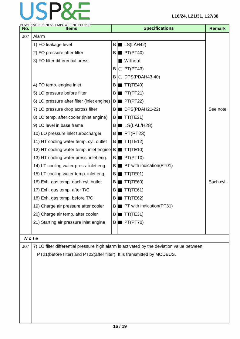
J07
1) FO leakage level B ■ LS(LAH42)
2) FO pressure after filter B ■ PT(PT40)
3) FO filter differential press. ■ Without
B ○ PT(PT43)
B ○ DPS(PDAH43-40)
4) FO temp. engine inlet B ■ TT(TE40)
5) LO pressure before filter B ■ PT(PT21)
6) LO pressure after filter (inlet engine) B ■ PT(PT22)
7) LO pressure drop across filter B ■ DPS(PDAH21-22) See note
8) LO temp. after cooler (inlet engine) B ■ TT(TE21)
9) LO level in base frame B ■ LS(LAL/H28)
10) LO pressure inlet turbocharger B ■ PT(PT23)
11) HT cooling water temp. cyl. outlet B ■ TT(TE12)
12) HT cooling water temp. inlet engine B ■ TT(TE10)
13) HT cooling water press. inlet eng. B ■ PT(PT10)
14) LT cooling water press. inlet eng. B ■
15) LT cooling water temp. inlet eng. B ■ TT(TE01)
16) Exh. gas temp. each cyl. outlet B ■ TT(TE60) Each cyl.
17) Exh. gas temp. after T/C B ■ TT(TE61)
18) Exh. gas temp. before T/C B ■ TT(TE62)
19) Charge air pressure after cooler B ■
20) Charge air temp. after cooler B ■ TT(TE31)
21) Starting air pressure inlet engine B ■ PT(PT70)
N o t e
J07
PT with indication(PT31)
7) LO filter differential pressure high alarm is activated by the deviation value between
PT21(before filter) and PT22(after filter). It is transmitted by MODBUS.
Alarm
PT with indication(PT01)
16 / 19
L16/24, L21/31, L27/38DOOSAN - MAN DIESELNo. Items RemarkSpecifications
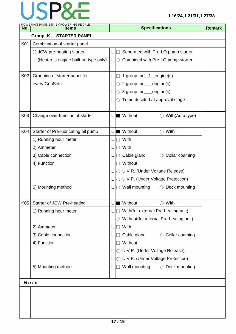
K01 Combination of starter panel
1) JCW pre-heating starter L □ Separated with Pre-LO pump starter
(Heater is engine built-on type only) L ◇ Combined with Pre-LO pump starter
K02 Grouping of starter panel for L □ 1 group for 1 engine(s)
every GenSets L ◇ 2 group for engine(s)
L ◇ 3 group for engine(s)
L ◇ To be decided at approval stage
K03 Change over function of starter L ■ Without ○ With(Auto type)
K04 Starter of Pre-lubricating oil pump L ■ Without ○ With
1) Running hour meter L □ With
2) Ammeter L □ With
3) Cable connection L □ Cable gland ◇ Collar coaming
4) Function □ Without
L ○
L ○
5) Mounting method L □ Wall mounting ◇ Deck mounting
K05 Starter of JCW Pre-heating L ■ Without ○ With
1) Running hour meter L □
◇
2) Ammeter L □ With
3) Cable connection L □ Cable gland ◇ Collar coaming
4) Function □ Without
L ○
L ○
5) Mounting method L □ Wall mounting ◇ Deck mounting
N o t e
U.V.R. (Under Voltage Release)
U.V.P. (Under Voltage Protection)
Group K STARTER PANEL
With(for external Pre-heating unit)
U.V.R. (Under Voltage Release)
U.V.P. (Under Voltage Protection)
Without(for internal Pre-heating unit)
17 / 19

L16/24, L21/31, L27/38DOOSAN - MAN DIESELNo. Items RemarkSpecifications
L01 Standard spare parts ● One(1) set See note
L02 Additional spare parts on request ○ sets
L03 Standard tools ● One(1) set See note
L04 Additional tools on request ○ sets
N o t e
L01
L03 In accordance with requirement of maker's standard.
In accordance with requirement of maker's standard.
Group L SPARE PARTS & TOOLS
18 / 19

L16/24, L21/31, L27/38DOOSAN - MAN DIESELNo. Items RemarkSpecifications
M01 Supplier □ Client ● Doosan
M02 Manufacturer
M03 Capacity for Type 1 See note
3 Ph, PF 0.8
M04 Power factor ● 0.8 lagging ○ 0.75 lagging
○ 0.9 lagging ○ Other:
M05 Enclosure ● IP23 ○ IP44
○ Other:
M06 Insulation class ● F ○ H
M07 Temperature rise ● F ○ H
M08 Bearing Q'ty ○
● Double bearing
M09 Bearing type ○ Maker standard ● Sleeve bearing
○ Anti friction bearing(ball bearing)
M10 Bearing lubrication ● Self-lubricating ○ Forced lubrication
M11 Cooling type ●
○
M12 Differential current transformer(DCT) ● 3ea for alternator ○ 3ea for MSBD
M13 Bearing temp. detector(Dial gauge) ● Without ○ With
M14 Water leakage detector for IP44 ● Without ○ With
M15 Air temp. detector for IP44 ● Without ○ With
M16 Cooling water temp. detector for IP44 ● Without ○ With
M17 Accessories ● Maker standard See note
L ● Other : Auto voltage regulator(1ea/alternator)
N o t e
M03 Refer to Note of "A10. 3)"
M17 Bearing temperature gauge : Dial thermometer
Stator winding temp. : Temp. sensor(PT100) x 6 ea (2 ea/phase : 1 working & 1 spare)
1881 kW, AC 6.6 kV, 1000 rpm, 50Hz
Hyosung Corporation
Group M ALTERNATOR & MISCELLANEOUS
Single bearing
IP23, by ventilation air
IP44, by water cooled air
19 / 19

L16/24, L21/31, L27/38
Attachment : Standard Instrument (L21/31)
No.
1
2
3 Fuel Oil - Inlet to Engine
Local Pressure Guage
Type
Pressure Gauge (PI10)
Pressure Gauge (PI22)
Pressure Gauge (PI40)
Function
HT Fresh Water - Inlet to Engine
Lubricating Oil - Outlet from Filter
1 / 1