C M Y CM MY CY CMY K GCS GROUND CONTROL SEGMENT
8
indracompany.com SPACE GROUND CONTROL SEGMENT Satellite communications, earth observation, navigation and positioning and control stations
Transcript of C M Y CM MY CY CMY K GCS GROUND CONTROL SEGMENT
gcs_af.fh11 9/3/10 18:52 P�gina 1
Composici�n
C M Y CM MY CY CMY K
SECURITY SYSTEMS
indracompany.com
SPACE
GROUND CONTROLSEGMENTSatellite communications, earth observation, navigation and positioningand control stations
C/ Mar Egeo, 4Polígono industrial, 128830 San Fernando de HenaresMadrid (Spain)T + 34 91 626 90 00F + 34 91 626 88 [email protected]
Indra reserves the rightto modify thesespecifications withoutprior notice.
GCS GROUND CONTROLSEGMENT
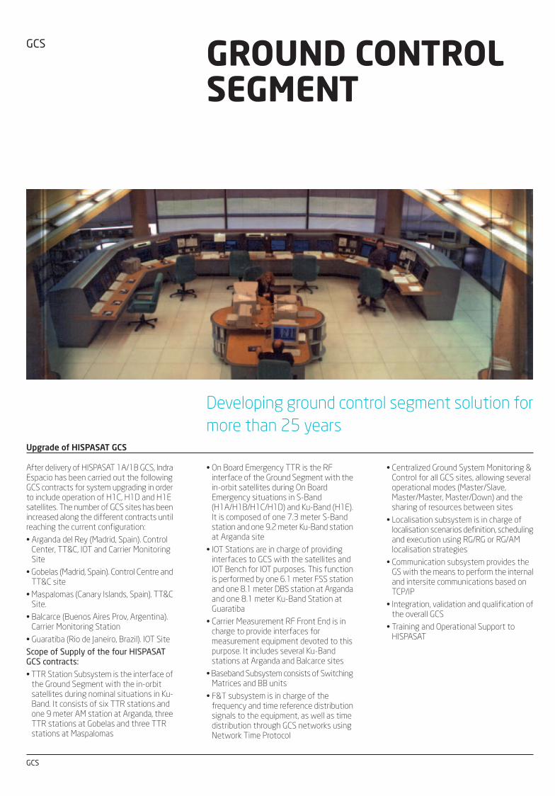
Upgrade of HISPASAT GCS
After delivery of HISPASAT 1A/1B GCS, IndraEspacio has been carried out the followingGCS contracts for system upgrading in orderto include operation of H1C, H1D and H1Esatellites. The number of GCS sites has beenincreased along the different contracts untilreaching the current configuration:
• Arganda del Rey (Madrid, Spain). ControlCenter, TT&C, IOT and Carrier MonitoringSite
• Gobelas (Madrid, Spain). Control Centre andTT&C site
• Maspalomas (Canary Islands, Spain). TT&CSite.
• Balcarce (Buenos Aires Prov, Argentina).Carrier Monitoring Station
• Guaratiba (Rio de Janeiro, Brazil). IOT Site
Scope of Supply of the four HISPASATGCS contracts:• TTR Station Subsystem is the interface of
the Ground Segment with the in-orbitsatellites during nominal situations in Ku-Band. It consists of six TTR stations andone 9 meter AM station at Arganda, threeTTR stations at Gobelas and three TTRstations at Maspalomas
• On Board Emergency TTR is the RFinterface of the Ground Segment with thein-orbit satellites during On BoardEmergency situations in S-Band(H1A/H1B/H1C/H1D) and Ku-Band (H1E).It is composed of one 7.3 meter S-Bandstation and one 9.2 meter Ku-Band stationat Arganda site
• IOT Stations are in charge of providinginterfaces to GCS with the satellites andIOT Bench for IOT purposes. This functionis performed by one 6.1 meter FSS stationand one 8.1 meter DBS station at Argandaand one 8.1 meter Ku-Band Station atGuaratiba
• Carrier Measurement RF Front End is incharge to provide interfaces formeasurement equipment devoted to thispurpose. It includes several Ku-Bandstations at Arganda and Balcarce sites
• Baseband Subsystem consists of SwitchingMatrices and BB units
• F&T subsystem is in charge of thefrequency and time reference distributionsignals to the equipment, as well as timedistribution through GCS networks usingNetwork Time Protocol
• Centralized Ground System Monitoring &Control for all GCS sites, allowing severaloperational modes (Master/Slave,Master/Master, Master/Down) and thesharing of resources between sites
• Localisation subsystem is in charge oflocalisation scenarios definition, schedulingand execution using RG/RG or RG/AMlocalisation strategies
• Communication subsystem provides theGS with the means to perform the internaland intersite communications based onTCP/IP
• Integration, validation and qualification ofthe overall GCS
• Training and Operational Support toHISPASAT
GCS
Developing ground control segment solution for
more than 25 years
TTC facility element for GALILEO
The TTC facility element comprises a numberof unique subsystems that perform thenecessary uplink, downlink, ranging,calibration and control and monitorprocessing functions for the TTCmanagement of the GALILEO constellationof satellites. During the IOV phase there willbe 2 TTC stations, while in the FOCconfiguration the number of stations willbe 5.
Each TTC station is composed of thefollowing subsystems:
• Antenna and tracking
• RF transmission
• RF reception
• Timing and frequency referencesgeneration and distribution
• Baseband units (including TM, TC andranging functions)
• Monitor and control subsystem
• Communications subsystem
• Calibration and testing
• Meteo
• Simulators
gcs_af.fh11 9/3/10 18:52 P�gina 1
Composici�n
C M Y CM MY CY CMY K
SECURITY SYSTEMS
indracompany.com
SPACE
GROUND CONTROLSEGMENTSatellite communications, earth observation, navigation and positioningand control stations
C/ Mar Egeo, 4Polígono industrial, 128830 San Fernando de HenaresMadrid (Spain)T + 34 91 626 90 00F + 34 91 626 88 [email protected]
Indra reserves the rightto modify thesespecifications withoutprior notice.
GCS GROUND CONTROLSEGMENT
Upgrade of HISPASAT GCS
After delivery of HISPASAT 1A/1B GCS, IndraEspacio has been carried out the followingGCS contracts for system upgrading in orderto include operation of H1C, H1D and H1Esatellites. The number of GCS sites has beenincreased along the different contracts untilreaching the current configuration:
• Arganda del Rey (Madrid, Spain). ControlCenter, TT&C, IOT and Carrier MonitoringSite
• Gobelas (Madrid, Spain). Control Centre andTT&C site
• Maspalomas (Canary Islands, Spain). TT&CSite.
• Balcarce (Buenos Aires Prov, Argentina).Carrier Monitoring Station
• Guaratiba (Rio de Janeiro, Brazil). IOT Site
Scope of Supply of the four HISPASATGCS contracts:• TTR Station Subsystem is the interface of
the Ground Segment with the in-orbitsatellites during nominal situations in Ku-Band. It consists of six TTR stations andone 9 meter AM station at Arganda, threeTTR stations at Gobelas and three TTRstations at Maspalomas
• On Board Emergency TTR is the RFinterface of the Ground Segment with thein-orbit satellites during On BoardEmergency situations in S-Band(H1A/H1B/H1C/H1D) and Ku-Band (H1E).It is composed of one 7.3 meter S-Bandstation and one 9.2 meter Ku-Band stationat Arganda site
• IOT Stations are in charge of providinginterfaces to GCS with the satellites andIOT Bench for IOT purposes. This functionis performed by one 6.1 meter FSS stationand one 8.1 meter DBS station at Argandaand one 8.1 meter Ku-Band Station atGuaratiba
• Carrier Measurement RF Front End is incharge to provide interfaces formeasurement equipment devoted to thispurpose. It includes several Ku-Bandstations at Arganda and Balcarce sites
• Baseband Subsystem consists of SwitchingMatrices and BB units
• F&T subsystem is in charge of thefrequency and time reference distributionsignals to the equipment, as well as timedistribution through GCS networks usingNetwork Time Protocol
• Centralized Ground System Monitoring &Control for all GCS sites, allowing severaloperational modes (Master/Slave,Master/Master, Master/Down) and thesharing of resources between sites
• Localisation subsystem is in charge oflocalisation scenarios definition, schedulingand execution using RG/RG or RG/AMlocalisation strategies
• Communication subsystem provides theGS with the means to perform the internaland intersite communications based onTCP/IP
• Integration, validation and qualification ofthe overall GCS
• Training and Operational Support toHISPASAT
GCS
Developing ground control segment solution for
more than 25 years
TTC facility element for GALILEO
The TTC facility element comprises a numberof unique subsystems that perform thenecessary uplink, downlink, ranging,calibration and control and monitorprocessing functions for the TTCmanagement of the GALILEO constellationof satellites. During the IOV phase there willbe 2 TTC stations, while in the FOCconfiguration the number of stations willbe 5.
Each TTC station is composed of thefollowing subsystems:
• Antenna and tracking
• RF transmission
• RF reception
• Timing and frequency referencesgeneration and distribution
• Baseband units (including TM, TC andranging functions)
• Monitor and control subsystem
• Communications subsystem
• Calibration and testing
• Meteo
• Simulators

gcs_af.fh11 9/3/10 18:52 P�gina 2
Composici�n
C M Y CM MY CY CMY K
SPACESPACESPACE SPACE
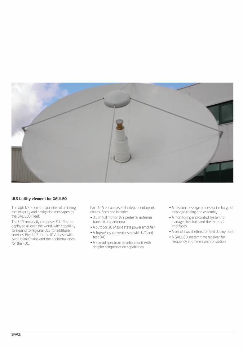
ULS facility element for GALILEO
The Uplink Station is responsible of uplinkingthe integrity and navigation messages tothe GALILEO Fleet.
The ULS nominally comprises 9 ULS sitesdeployed all over the world, with capabilityto expand to regional ULS for additonalservices. Five ULS for the IOV phase withtwo Uplink Chains and the additional onesfor the FOC.
Each ULS encompases 4 independent uplinkchains. Each one inlcudes:
• 3.5 m full motion X/Y pedestal antennatransmitting antenna
• A outdoor 30 W solid state power amplifier
• A frqeuency converter set, with U/C andtest D/C
• A spread spectrum baseband unit withdoppler compensation capabilities
Development of SpainSat GCS architecture
• RF subsystem composed of A1 and A2stations at primary site and A6 station atbackup site
• IF subsystem consisting of switchingmatrices and BB units
• F&T subsystem in charge of the frequencyand time reference distribution signals toSpainSat and Xtar equipment
• M&C subsystem implemented is IndraGenius M&C tool
• Internal communication subsystem for theGCS. It was developed on TCP/IP
• Localisation subsystem in charge oflocalisation scenarios definition, schedulingand execution using RG/RG or RG/AMlocalisation strategies. Arganda andMaspalomas LOC’s will conduct localisationscenarios in a coordinated manner
The SpainSat Ground Control Segment (GCS)has been implemented in two sites: a primarysite at Arganda (near Madrid) and a backupsite at Maspalomas (Canary Islands). Anumber of subsystems in this GCS are alsoused for Xsat mission. The followingsubsystems are considered as part ofSpainSat Ground Control Segment supplycontract:
Spain Sat GCS includes interfaces with thefollowing subsystems that are not part ofthe contract:
• SpainSat Flight Dynamic Subsystem (FDS)
• SpainSat SCC subsystem
• SpainSat Dynamic Software SatelliteSimulator (DSSS)
• Payload Monitoring Subsystem (PMC)
Development of Amazonas GCS
The Amazonas GCS is the set of facilities incharge of controlling and monitoringAmazonas satellites (AMZ-1 and AMZ-2).GCS configuration copes with the receptionof continuous satellite telemetry, spacecrafttelecommand, ranging and tracking in orderto provide information about health statusand satellite positioning. The GCS allows toperform IOT campaign, VERA tests andcarrier monitoring functions.
GCS sites are:
• RIO 1 (Rio de Janeiro, Brazil)
• RIO 2 (Rio de Janeiro, Brazil)
• ARGANDA (Arganda del Rey, Spain)
• MASPALOMAS (Canary Islands, Spain)
• New site (USA)
• Gobelas
The GCS of Amazonas includes:• TTR Station Subsystem is the interface of
the Ground Segment with the in-orbitsatellites (AMZ-1 and AMZ-2) duringNominal situations and consists on R-TTR1(8.1 meters), A-TTR5 (3.7 meters), and C-TTR2 (3.8 meters). All stations aredesigned to operate in Ku-band
• On Board Emergency TTR is the RFinterface of the Ground Segment with in-orbit satellites (AMZ-1 and AMZ-2) duringOn Board Emergency situations andconsists on a Station placed at ARGANDA(A-EMS-1)
• IOT Stations are in charge of providinginterfaces to GCS with the satellite for IOTpurposes. This function is performed byR-TTR1/IOT for Ku-band payload inAmerica, RIOT/C for C-band payload inAmerica and A-IOT/FSS for Ku-bandpayload in Europe
• Carrier access and payload monitoring incharge of providing interfaces formeasurement equipment devoted to thispurpose
• Baseband subsystem consists of switchingmatrices and BB units
• F&T subsystem in charge of the frequencyand time reference distribution signals tothe equipment, as well as time distributionthrough Amazonas networks usingnetwork time protocol
• GMC subsystem is in charge of themanagement of the different GCSequipment configuration, maintenance andevent reporting
• Communication subsystem provides theGCS with the means to perform the internaland intersite communications based onTCP/IP
• Localisation subsystem in charge oflocalisation scenarios definition, schedulingand execution using RG/RG or RG/AMlocalisation strategies
Polar Station Facility (PSF)
Two Command and Data Acquisition (CDA)stations placed in Svalbard (Norway)These stations are able to work in S, X, Land VHF bands providing the followingfunctions:
• TT&C activities for METOP satellites in S-Band: These TT&C data sets will bearchived locally and sent to/fromEUMETSAT headquarters in Darmstadt viathe intersite network
• TT&C activities for NOAA satellites in S-Band: These TT&C data sets will bearchived locally and sent to/fromEUMETSAT headquarters in Darmstadt
• GDS Data acquisition from METOPsatellites in X-Band to be processed locallyby the FEP before to be sending toEUMETSAT headquarters
• GAC Data acquisition from NOAA satellitesin L-Band to be processed locally by theFEP before to be sending to EUMETSATheadquarters
• L-Band HRPT and VHF-band LRPT carriersmonitoring from METOP satellites
The main role of the PSF is to acquire signalsfrom polar orbiting satellites and to ensurethe control of such satellites. Two kind ofsatellites are considered:
• European METOP 1, 2 and 3 of EUMETSAT
• US NOAA N and N’ of NOAA
The PSF is composed of three earth stations:
One Reference User Station (RUS) locatedat EUMESAT headquarters in Darmstadt(Germany)This station will be used by operators asreference station and will provide L-bandHRPT and VHF-band LRPT carriersacquisition and transmission to a dedicatedFEP.
• A mission message processor in charge ofmessage coding and assembly
• A monitoring and control system tomanage the chain and the externalinterfaces
• A set of two shelters for field deployment
• A GALILEO system time receiver forfrequency and time synchronization

gcs_af.fh11 9/3/10 18:52 P�gina 2
Composici�n
C M Y CM MY CY CMY K
SPACESPACESPACE SPACE
ULS facility element for GALILEO
The Uplink Station is responsible of uplinkingthe integrity and navigation messages tothe GALILEO Fleet.
The ULS nominally comprises 9 ULS sitesdeployed all over the world, with capabilityto expand to regional ULS for additonalservices. Five ULS for the IOV phase withtwo Uplink Chains and the additional onesfor the FOC.
Each ULS encompases 4 independent uplinkchains. Each one inlcudes:
• 3.5 m full motion X/Y pedestal antennatransmitting antenna
• A outdoor 30 W solid state power amplifier
• A frqeuency converter set, with U/C andtest D/C
• A spread spectrum baseband unit withdoppler compensation capabilities
Development of SpainSat GCS architecture
• RF subsystem composed of A1 and A2stations at primary site and A6 station atbackup site
• IF subsystem consisting of switchingmatrices and BB units
• F&T subsystem in charge of the frequencyand time reference distribution signals toSpainSat and Xtar equipment
• M&C subsystem implemented is IndraGenius M&C tool
• Internal communication subsystem for theGCS. It was developed on TCP/IP
• Localisation subsystem in charge oflocalisation scenarios definition, schedulingand execution using RG/RG or RG/AMlocalisation strategies. Arganda andMaspalomas LOC’s will conduct localisationscenarios in a coordinated manner
The SpainSat Ground Control Segment (GCS)has been implemented in two sites: a primarysite at Arganda (near Madrid) and a backupsite at Maspalomas (Canary Islands). Anumber of subsystems in this GCS are alsoused for Xsat mission. The followingsubsystems are considered as part ofSpainSat Ground Control Segment supplycontract:
Spain Sat GCS includes interfaces with thefollowing subsystems that are not part ofthe contract:
• SpainSat Flight Dynamic Subsystem (FDS)
• SpainSat SCC subsystem
• SpainSat Dynamic Software SatelliteSimulator (DSSS)
• Payload Monitoring Subsystem (PMC)
Development of Amazonas GCS
The Amazonas GCS is the set of facilities incharge of controlling and monitoringAmazonas satellites (AMZ-1 and AMZ-2).GCS configuration copes with the receptionof continuous satellite telemetry, spacecrafttelecommand, ranging and tracking in orderto provide information about health statusand satellite positioning. The GCS allows toperform IOT campaign, VERA tests andcarrier monitoring functions.
GCS sites are:
• RIO 1 (Rio de Janeiro, Brazil)
• RIO 2 (Rio de Janeiro, Brazil)
• ARGANDA (Arganda del Rey, Spain)
• MASPALOMAS (Canary Islands, Spain)
• New site (USA)
• Gobelas
The GCS of Amazonas includes:• TTR Station Subsystem is the interface of
the Ground Segment with the in-orbitsatellites (AMZ-1 and AMZ-2) duringNominal situations and consists on R-TTR1(8.1 meters), A-TTR5 (3.7 meters), and C-TTR2 (3.8 meters). All stations aredesigned to operate in Ku-band
• On Board Emergency TTR is the RFinterface of the Ground Segment with in-orbit satellites (AMZ-1 and AMZ-2) duringOn Board Emergency situations andconsists on a Station placed at ARGANDA(A-EMS-1)
• IOT Stations are in charge of providinginterfaces to GCS with the satellite for IOTpurposes. This function is performed byR-TTR1/IOT for Ku-band payload inAmerica, RIOT/C for C-band payload inAmerica and A-IOT/FSS for Ku-bandpayload in Europe
• Carrier access and payload monitoring incharge of providing interfaces formeasurement equipment devoted to thispurpose
• Baseband subsystem consists of switchingmatrices and BB units
• F&T subsystem in charge of the frequencyand time reference distribution signals tothe equipment, as well as time distributionthrough Amazonas networks usingnetwork time protocol
• GMC subsystem is in charge of themanagement of the different GCSequipment configuration, maintenance andevent reporting
• Communication subsystem provides theGCS with the means to perform the internaland intersite communications based onTCP/IP
• Localisation subsystem in charge oflocalisation scenarios definition, schedulingand execution using RG/RG or RG/AMlocalisation strategies
Polar Station Facility (PSF)
Two Command and Data Acquisition (CDA)stations placed in Svalbard (Norway)These stations are able to work in S, X, Land VHF bands providing the followingfunctions:
• TT&C activities for METOP satellites in S-Band: These TT&C data sets will bearchived locally and sent to/fromEUMETSAT headquarters in Darmstadt viathe intersite network
• TT&C activities for NOAA satellites in S-Band: These TT&C data sets will bearchived locally and sent to/fromEUMETSAT headquarters in Darmstadt
• GDS Data acquisition from METOPsatellites in X-Band to be processed locallyby the FEP before to be sending toEUMETSAT headquarters
• GAC Data acquisition from NOAA satellitesin L-Band to be processed locally by theFEP before to be sending to EUMETSATheadquarters
• L-Band HRPT and VHF-band LRPT carriersmonitoring from METOP satellites
The main role of the PSF is to acquire signalsfrom polar orbiting satellites and to ensurethe control of such satellites. Two kind ofsatellites are considered:
• European METOP 1, 2 and 3 of EUMETSAT
• US NOAA N and N’ of NOAA
The PSF is composed of three earth stations:
One Reference User Station (RUS) locatedat EUMESAT headquarters in Darmstadt(Germany)This station will be used by operators asreference station and will provide L-bandHRPT and VHF-band LRPT carriersacquisition and transmission to a dedicatedFEP.
• A mission message processor in charge ofmessage coding and assembly
• A monitoring and control system tomanage the chain and the externalinterfaces
• A set of two shelters for field deployment
• A GALILEO system time receiver forfrequency and time synchronization

C/ Mar Egeo, 4Polígono industrial, 128830 San Fernando de HenaresMadrid (Spain)T + 34 91 627 30 00F + 34 91 627 30 [email protected]
Indra reserves the rightto modify thesespecifications withoutprior notice.
![C M Y CM MY CY CMY K - Unus International | DC motorsweb].pdf · Y CM MY CY CMY K. C M Y CM MY CY CMY K. QUALITY The Unus International Quality Assurance System is certified ISO 9001:2008](https://static.fdocuments.in/doc/165x107/5bd577fa09d3f27b3e8bb28f/c-m-y-cm-my-cy-cmy-k-unus-international-dc-webpdf-y-cm-my-cy-cmy-k-c.jpg)