C Clamp-On Ultrasonic Flowmeter - Aysix Technologies
12
A NALYSIS | C ONTROL | F LOW | L EVEL | L OGGERS | W IRELESS Aysix 150 Flowmeter Clamp-On Ultrasonic Flowmeter The clamp-on ultrasonic flowmeters work on the transit-time method. This is based on the principle that sound waves travelling with the flow will move faster than those travelling against it. The resulting difference in transit time is directly proportional to the flow velocity of the liquid and consequently to the volumetric flow rate. The ultrasonic transducers (sensors) of the flow- meter are mounted on the external surface of the pipe and are used to generate and receive pulses. The flowing liquid within causes time differences in the ultrasonic signals, which are evaluated by the flowmeter to produce an accurate flow measurement. The advanced electronics of the flowmeter compensate for and adapt to changes in the flow profile and medium temperature to deliver reliable measurements. The 150 is a fixed-installation clamp-on ultrasonic flow meter for non-invasive and non-intrusive flow measurement of liquids and liquefied gases in fully filled pipes. It can be supplied with one or two measurement channels. This enables the flowmeter to simultaneously monitor up to two separate pipes. Alternatively, a dual-channel setup can be used for a two-path mouthing configuration of the sensors on the one single pipe. Additionally, the 150 offers optional functions for heat quantity and concentration measurement with process input, output and serial communication options available. These features are complemented by an optional internal datalogger and software for the recording and download of measured values. Thanks to its intuitive instrument menu, Setup Wizard, and Audible Sensor Positioning Assistant™ the flow- meter can be set up and its sensors correctly installed in a matter of minutes. Optional transmitter and transducer versions are available for installation in hazardous areas. Flowmeter with one of two measurement channels, graphic LCD display, internal datalogger & input/output options For commonly used pipe materials and diameters from 10 mm to over 3.0 mm Intuitive menu, Setup Wizard and Audible Sensor Positioning Assistant™ for easy and quick setup and installation Transit-time correlation measurement using dual DSP-technology for better measurement accuracy Heat quantity measurement capability and Ex approved instrument versions AC, DC and solar panel power supply Features • Lockable and sturdy IP 66 transmitter enclosure with keypad and multifunctional display • Bi-directional measurement with totalizer function and process input, output and serial communication options including Modbus RTU and HART • Available with optional heat quantity measurement function and PT100 clamp-on sensors for contactless metering of thermal energy consumption • Optional sound velocity output function for contactless product recognition and interface detection; optional internal data logger for up to 100,000 measurements • Transmitter and transducer options approved for use in hazardous area Zone 1 or 2 • Software for offline/online data transfer via RS 232 or USB cable
Transcript of C Clamp-On Ultrasonic Flowmeter - Aysix Technologies
AN
ALY
SIS
| CO
NT
RO
L | FLOW
| LE
VE
L | LO
GG
ER
S | W
IRE
LES
S
Aysix 150 Flowmeter
Clamp-On UltrasonicFlowmeterThe clamp-on ultrasonic flowmeters work on thetransit-time method. This is based on theprinciple that sound waves travelling with theflow will move faster than those travelling againstit. The resulting difference in transit time is directly proportional to the flow velocity of theliquid and consequently to the volumetric flowrate.
The ultrasonic transducers (sensors) of the flow-meter are mounted on the external surface ofthe pipe and are used to generate and receivepulses. The flowing liquid within causes timedifferences in the ultrasonic signals, which are evaluated by the flowmeter to produce anaccurate flow measurement. The advancedelectronics of the flowmeter compensate forand adapt to changes in the flow profile andmedium temperature to deliver reliablemeasurements.
The 150 is a fixed-installation clamp-on ultrasonicflow meter for non-invasive and non-intrusive flowmeasurement of liquids and liquefied gases infully filled pipes. It can be supplied with one ortwo measurement channels. This enables theflowmeter to simultaneously monitor up to twoseparate pipes. Alternatively, a dual-channelsetup can be used for a two-path mouthingconfiguration of the sensors on the one singlepipe. Additionally, the 150 offers optionalfunctions for heat quantity and concentrationmeasurement with process input, output andserial communication options available.
These features are complemented by an optionalinternal datalogger and software for the recordingand download of measured values. Thanks toits intuitive instrument menu, Setup Wizard, andAudible Sensor Positioning Assistant™ the flow-meter can be set up and its sensors correctlyinstalled in a matter of minutes. Optionaltransmitter and transducer versions are available for installation in hazardous areas.
Flowmeter with one of two measurement channels, graphic LCD display, internal datalogger & input/output options For commonly used pipe materials and diameters from 10 mm to over 3.0 mm Intuitive menu, Setup Wizard and Audible Sensor Positioning Assistant™ for easy and quick setup and installation Transit-time correlation measurement using dual DSP-technology for better measurement accuracy Heat quantity measurement capability and Ex approved instrument versions AC, DC and solar panel power supply
Features• Lockable and sturdy IP 66 transmitter enclosure with keypad and multifunctional display• Bi-directional measurement with totalizer function and process input, output and serial communication options including Modbus RTU and HART• Available with optional heat quantity measurement function and PT100 clamp-on sensors for contactless metering of thermal energy consumption• Optional sound velocity output function for contactless product recognition and interface detection; optional internal data logger for up to 100,000 measurements• Transmitter and transducer options approved for use in hazardous area Zone 1 or 2• Software for offline/online data transfer via RS 232 or USB cable
Specifications: Transmitter
Performance Measurement Principle: Ultrasonic transit-time difference correlation Flow Velocity Range: 0.01 ... 25 m/s Resolution: 0.25 mm/s Repeatability: 0.15% of measured value, ±0.015 rnls Accuracy: Volume flow ±1 ... 3% of measured value depending on application ±0.5% of measured value with process calibration Flow velocity (mean) ±0.5 % of measured value Turn Down Ratio: 1/100 Measurement Rate: 1 Hz as standard, higher rates on application Response Time: 1 s, 70m/s (optional) Damping of Displayed Value: 0 ...99 s (selectable by user) Gaseous and Solid Content < 10% of volume of Liquid Media:
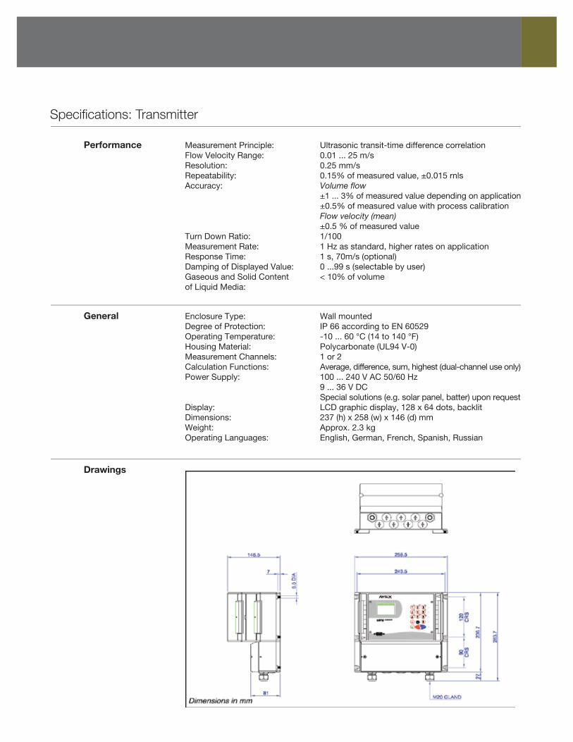
General Enclosure Type: Wall mounted Degree of Protection: IP 66 according to EN 60529 Operating Temperature: -10 ... 60 °C (14 to 140 °F) Housing Material: Polycarbonate (UL94 V-0) Measurement Channels: 1 or 2 Calculation Functions: Average, difference, sum, highest (dual-channel use only) Power Supply: 100 ... 240 V AC 50/60 Hz 9 ... 36 V DC Special solutions (e.g. solar panel, batter) upon request Display: LCD graphic display, 128 x 64 dots, backlit Dimensions: 237 (h) x 258 (w) x 146 (d) mm Weight: Approx. 2.3 kg Operating Languages: English, German, French, Spanish, Russian
Drawings
Specifications: Transmitter (Continued)
Images
Communication Type: RS 232, USB converter cable (optional), RS 485 (optional), Modbus RTU (optional) Transmitted Data: Measured and totalized value, parameter set and configuration, loggged data
Internal data Storage Capcity: Approx. 30,000 measurements (each comprising up to logger 10 selectable measurement units), logger size 5 MB Approx. 100,000 measurements (each comprising up to 10 selectable measurement units), logger size 16 MB Logged Data: All measured and totalized values, parameter sets
KATdata+ Functionality: Download of measured value/parameter sets, graphical software presentation, list format, export to third party software, online transfer of measured data Operating Systems: Windows 7, Vista, XP, NT, 2000, Linux, Mac (optional)
Quantity & units Volumetric Flow Rate: m3/h, m3/min, m3/s, I/h, I/min, I/s, USgal/h (US gallons per of measurements hour), USgal/min, USgal/s, bbl/d (barrels per day), bbl/h, bbl/min Flow Velocity: m/s, ft/s, inch/s Mass Flow Rate: g/s, t/h, kg/h, kg/min Volume: m3, I, gal (US gallons), bbl Mass: g, kg, t Heat Flow: W, kW, MW (only with heat quantity measurement option) Heat Quantity: J, kJ, MJ (only with heat quantity measurement option) Temperature: °C (only with heat quantity measurement option)
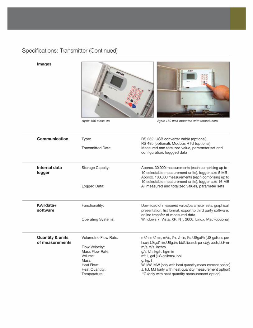
Aysix 150 close-up Aysix 150 wall-mounted with transducers
Specifications: Transmitter (Continued)
Process inputs Temperature: PT100 (clamp-on sensors), four-wire circuit, (galvanically isolated) measurement rante -50 ... 400 ºC (-58 ... 752 ºF), resolution 0.1 K, accuracy ± 0.2 K (one, two or four inputs available) Current: 0/4 ... 20 mA active or 0/4 ... 20 mA passive, U = 30 V, R1 = 50 , accuracy 0.1% of measured value
Process outputs Current: 0/4 ... 20 mA active/passive (RLoad < 500 ), 16 bit (galvanically isolated) resolution, U = 30 V, accuracy = 0.1% Voltage: 0 ... 10 V, RLoad = 1000 Frequency: 0 ... 10 kHz, 24 V/4 mA HART: 0/4 ... 20 mA, 24 V DC, RGND = 220 Digital Open-Collector: Value 0.01 ... 1000/unit, width 1 ... 990 ms, U = 24 V, Imax = 4mA Digital relay: Form C (SPDT-CO) contacts, U = 48 V, Imax = 250 mA
Specifications: PT100 Clamp-On Sensors
Process inputs Type: PT100 (clamp-on) logger Measurement range: -30 ... 250 ºC (-22 ... 482 ºF) Design: 4-wire Accuracy T: ± (0.15 ºC + 2 x 10⁻³ x T [ºC]), class A Accuracy ΔT: ≤ 0.1 K (3 K < ΔT < 6 K), corresponding to EN 1434-1 Response time: 50s Dimensions of sensor head: 20 (h) x 15 (w) x 15 (d) mm Material of sensor head: Aluminum Material cable jacket: PTFE Cable length: 3 m
Images
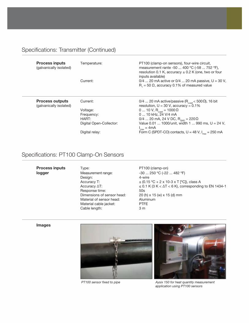
PT100 sensor fixed to pipe Aysix 150 for heat quantity measurementapplication using PT100 sensors
Specifications: Hazardous Area Transmitter Enclosure
General Enclosure Type: Wall mounted (additional to Aysix 150 transmitter) Degree of protection: IP 66 according to EN 60529 Operating temperature: -20 ... 40 ºC (-4 ... 104 ºF) Housing material: Grade LM6 cast alloy Finish: RAL 7035 epoxy powder coat Dimensions: 358 (h) x 278 (w) x 268 (d) m Weight: Approx. 20.0 kg (with Aysix 150 transmitter) Ex certification code: Ex II 2 GD Ex-d IIB+ H2 T4/T5/T6 IP65/66/67 Ex certification number: CESI 01 ATEX 027
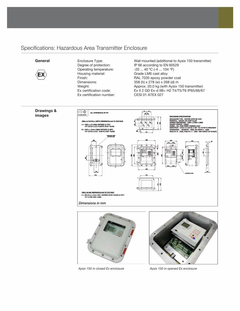
Drawings & images
Aysix 150 in closed Ex enclosure Aysix 150 in opened Ex enclosure
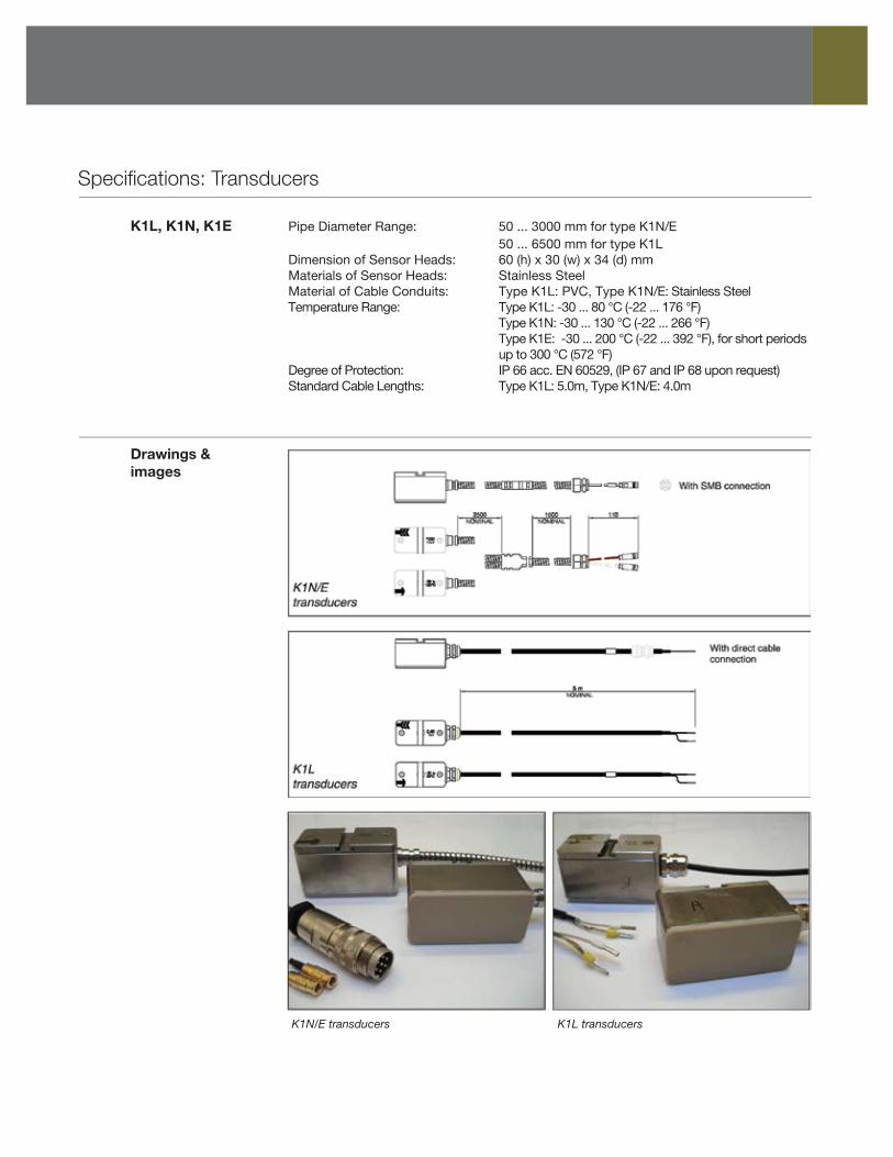
Specifications: Transducers
K1L, K1N, K1E Pipe Diameter Range: 50 ... 3000 mm for type K1N/E 50 ... 6500 mm for type K1L Dimension of Sensor Heads: 60 (h) x 30 (w) x 34 (d) mm Materials of Sensor Heads: Stainless Steel Material of Cable Conduits: Type K1L: PVC, Type K1N/E: Stainless Steel Temperature Range: Type K1L: -30 ... 80 °C (-22 ... 176 °F) Type K1N: -30 ... 130 °C (-22 ... 266 °F) Type K1E: -30 ... 200 °C (-22 ... 392 °F), for short periods up to 300 °C (572 °F) Degree of Protection: IP 66 acc. EN 60529, (IP 67 and IP 68 upon request) Standard Cable Lengths: Type K1L: 5.0m, Type K1N/E: 4.0m
Drawings & images
K1N/E transducers K1L transducers
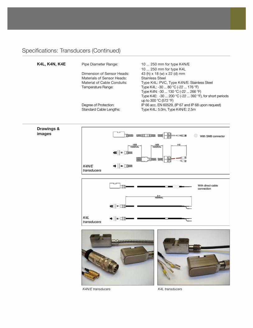
Specifications: Transducers (Continued)
K4L, K4N, K4E Pipe Diameter Range: 10 ... 250 mm for type K4N/E 10 ... 250 mm for type K4L Dimension of Sensor Heads: 43 (h) x 18 (w) x 22 (d) mm Materials of Sensor Heads: Stainless Steel Material of Cable Conduits: Type K4L: PVC, Type K4N/E: Stainless Steel Temperature Range: Type K4L: -30 ... 80 °C (-22 ... 176 °F) Type K4N: -30 ... 130 °C (-22 ... 266 °F) Type K4E: -30 ... 200 °C (-22 ... 392 °F), for short periods up to 300 °C (572 °F) Degree of Protection: IP 66 acc. EN 60529, (IP 67 and IP 68 upon request) Standard Cable Lengths: Type K4L: 5.0m, Type K4N/E: 2.5m
Drawings & images
K4N/E transducers K4L transducers
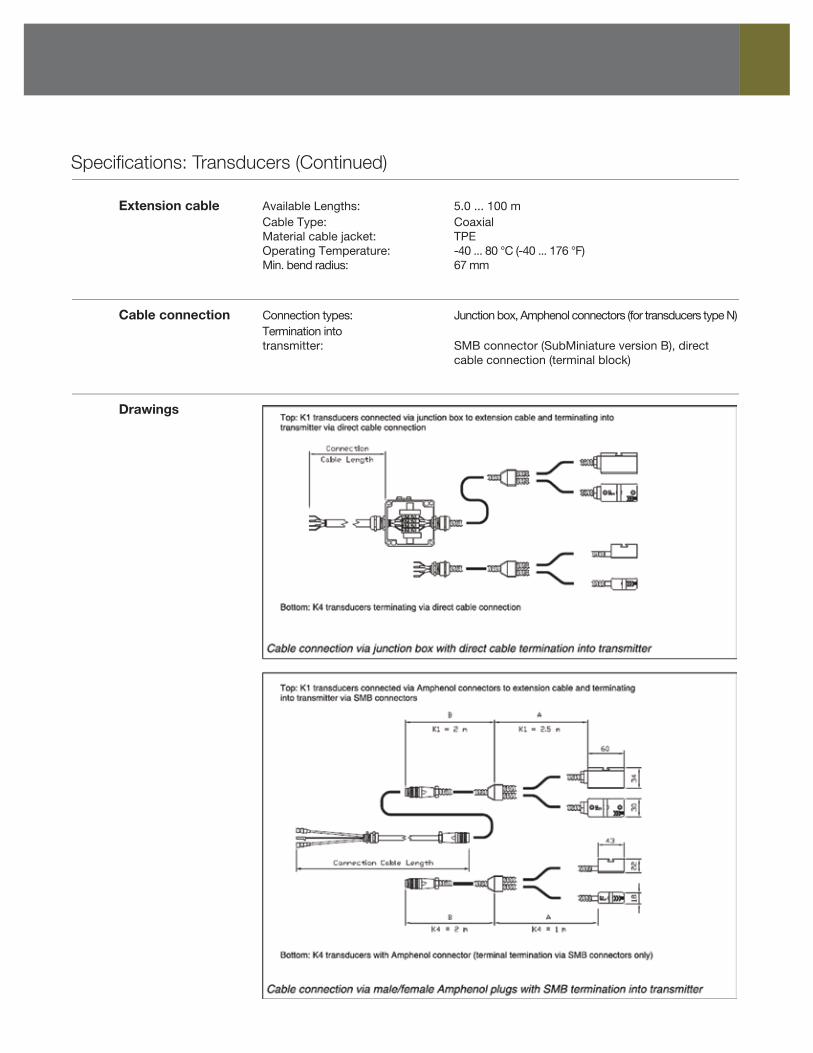
Specifications: Transducers (Continued)
Extension cable Available Lengths: 5.0 ... 100 m Cable Type: Coaxial Material cable jacket: TPE Operating Temperature: -40 ... 80 °C (-40 ... 176 °F) Min. bend radius: 67 mm
Drawings
Cable connection Connection types: Junction box, Amphenol connectors (for transducers type N) Termination into transmitter: SMB connector (SubMiniature version B), direct cable connection (terminal block)
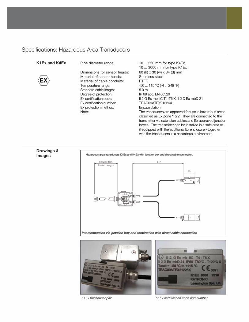
Specifications: Hazardous Area Transducers
K1Ex and K4Ex Pipe diameter range: 10 ... 250 mm for type K4Ex 10 ... 3000 mm for type K1Ex Dimensions for sensor heads: 60 (h) x 30 (w) x 34 (d) mm Material of sensor heads: Stainless steel Material of cable conduits: PTFE Temperature range: -50 ... 115 °C (-4 ... 248 °F) Standard cable length: 5.0 m Degree of protection: IP 68 acc. EN 60529 Ex certification code: II 2 G Ex mb IIC T4-T6 X, II 2 D Ex mbD 21 Ex certification number: TRAC09ATEX21226X Ex protection method: Encapsulation Note: The transducers are approved for use in hazardous areas classified as Ex Zone 1 & 2. They are connected to the transmitter via extension cables and Ex approved junction boxes. The transmitter can be installed in a safe area or - if equipped with the additional Ex enclosure - together with the transducers in a hazardous environment
Drawings & Images
K1Ex transducer pair K1Ex certification code and number
Specifications: Transducer Mounting Accessories
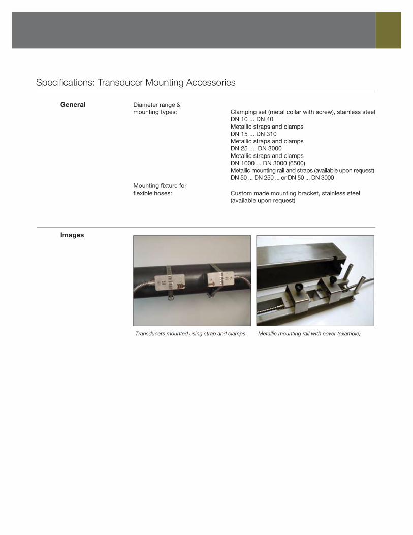
General Diameter range & mounting types: Clamping set (metal collar with screw), stainless steel DN 10 ... DN 40 Metallic straps and clamps DN 15 ... DN 310 Metallic straps and clamps DN 25 ... DN 3000 Metallic straps and clamps DN 1000 ... DN 3000 (6500) Metallic mounting rail and straps (available upon request) DN 50 ... DN 250 ... or DN 50 ... DN 3000 Mounting fixture for flexible hoses: Custom made mounting bracket, stainless steel (available upon request)
Images
Transducers mounted using strap and clamps Metallic mounting rail with cover (example)
Configuration Code: Transmitter & Accessories
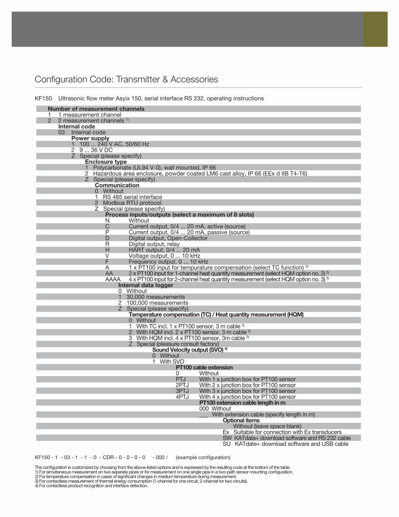
KF150 Ultrasonic flow meter Asyix 150, serial interface RS 232, operating instructions
Number of measurement channels 1 1 measurement channel 2 2 measurement channels 1)
Internal code 03 Internal code Power supply 1 100 ... 240 V AC, 50/60 Hz 2 9 ... 36 V DC Z Special (please specify) Enclosure type 1 Polycarbonate (UL94 V-0), wall mounted, IP 66 2 Hazardous area enclosure, powder coated LM6 cast alloy, IP 66 (EEx d IIB T4-T6) Z Special (please specify) Communication 0 Without 1 RS 485 serial interface 2 Modbus RTU protocol Z Special (please specify) Process inputs/outputs (select a maximum of 8 slots) N Without C Current output, 0/4 ... 20 mA, active (source) P Current output, 0/4 ... 20 mA, passive (source) D Digital output, Open-Collector R Digital output, relay H HART output, 0/4 ... 20 mA V Voltage output, 0 ... 10 kHz F Frequency output, 0 ... 10 kHz A 1 x PT100 input for tempurature compensation (select TC function) 2)
AA 2 x PT100 input for 1-channel heat quantity measurement (select HQM option no. 2) 3)
AAAA 4 x PT100 input for 2-channel heat quantity measurement (select HQM option no. 3) 3)
Internal data logger 0 Without 1 30,000 measurements 2 100,000 measurements Z Special (please specify) Temperature compensation (TC) / Heat quantity measurement (HQM) 0 Without 1 With TC incl. 1 x PT100 sensor, 3 m cable 2)
2 With HQM incl. 2 x PT100 sensor, 3 m cable 3)
3 With HQM incl. 4 x PT100 sensor, 3m cable 3)
Z Special (pleasure consult factory) Sound Velocity output (SVO) 4)
0 Without 1 With SVO PT100 cable extension 0 Without PTJ With 1 x junction box for PT100 sensor 2PTJ With 2 x junction box for PT100 sensor 3PTJ With 3 x junction box for PT100 sensor 4PTJ With 4 x junction box for PT100 sensor PT100 extension cable length in m 000 Without ___ With extension cable (specify length in m) Optional items Without (leave space blank) Ex Suitable for connection with Ex transducers SW KATdata+ download software and RS 232 cable SU KATdate+ download software and USB cable KF150 - 1 - 03 - 1 - 1 - 0 - CDR - 0 - 0 - 0 - 0 - 000 / (example configuration)
The configuration is customized by choosing from the above-listed options and is expressed by the resulting code at the bottom of the table.1) For simultaneous measurement on two seperate pipes or for measurement on one single pipe in a two-path sensor mounting configuration.2) For temperature compensation in cases of significant changes in medium temperature during measurement.3) For contactless measurement of thermal energy consumption (1-channel for one circuit, 2-channel for two circuits).4) For contactless product recognition and interface detection.
www.aysix.com [email protected]
Cancoppas MississaugaPhone: (905) 569-6246 or (800) 595-0514 Fax: (905) 569-6244 2595 Dunwin Dr., Unit #2, Mississauga, ON L5L 3N9
Cancoppas Québec LtéeTéléphone:(514) 697-4202 Télécopieur: (514) 697-6292880 Ave Selkirk, Pointe-Claire, QC, H9R 3S3
We reserve the right to change any content in this literature at any time. Our products evolve and improve to serve you better. 3612
Configuration Code: Transducers & Accessories
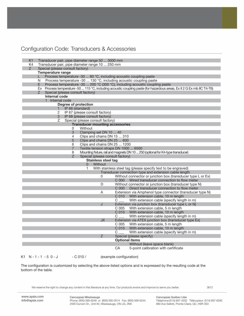
K1 Transducer pair, pipe diameter range 50 ... 3000 mm K4 Transducer pair, pipe diameter range 10 ... 250 mm Z Special (please consult factory) Temperature range L Process temperature -30 ... 80 °C, including acoustic coupling paste N Process temperature -30 ... 130 °C, including acoustic coupling paste E Process temperature -30 ... 200 °C (300 °C), including acoustic coupling paste Ex Process temperature -50 ... 115 °C, including acoustic coupling paste (for hazardous areas, Ex II 2 G Ex mb IIC T4-T6) Z Special (please consult factory) Internal code 1 Internal code Degree of protection 1 IP 66 (standard) 2 IP 67 (please consult factory) 3 IP 68 (please consult factory) Z Special (please consult factory) Transducer mounting accessories 0 Without 3 Clamping set DN 10 ... 40 4 Clips and chains DN 15 ... 310 5 Clips and chains DN 25 ... 600 6 Clips and chains DN 25 ... 1200 7 Textile tension straps DN 1000 ... 6500 8 Mounting fixture, rail and magnets DN 10 ... 250 (optional for K4-type transducer) Z Special (please consult factory) Stainless steel tag 0 Without 1 With stainless steel tag (please specify text to be engraved) Transducer connection type and extension cable length 0 Without connector or junction box (transducer type L or Ex) C 000 Wired transducer connection to flow meter D Without connector or junction box (transducer type N) C 000 Direct transducer connection to flow meter A Extension via Amphenol type connector (transducer type N) C 010 With extension cable, 10 m length C ___ With extension cable (specify length in m) J Extension via junction box (transducer type L or N) C 005 With extension cable, 5 m length C 010 With extension cable, 10 m length C ___ With extension cable (specify length in m) JX Extension via ATEX junction box (transducer type Ex) C 005 With extension cable, 5 m length C 010 With extension cable, 10 m length C ___ With extension cable (specify length in m) Z Special (please specify) Optional items Without (leave space blank) CA 5-point calibration with certificate
K1 N - 1 - 1 - 5 0 - J - C 010 / (example configuration)
The configuration is customized by selecting the above-listed options and is expressed by the resulting code at the bottom of the table.