C-Bus Basic Training Manual Volume 2 - Домашняя...
120
C-Bus ® Basic Training Manual Volume 2 2A. C-Bus® Toolkit Software 2B. Basic Programming 2C. Advanced Programming 2D. DLT 2E. Network Bridges 2F. Fault Finding Revision Number: V2
Transcript of C-Bus Basic Training Manual Volume 2 - Домашняя...
C-Bus® Basic Training Manual Volume 2
2A. C-Bus® Toolkit Software
2B. Basic Programming
2C. Advanced Programming
2D. DLT
2E. Network Bridges
2F. Fault Finding
Revision Number: V2

C-BUS TRAINING MANUAL - VOL 22
© Copyright Clipsal Australia Pty Ltd 2007. All rights reserved. This material is copyright under Australian and international laws. Except as permitted under the relevant law, no part of this work may be reproduced by any process without prior written permission of and acknowledgement to Clipsal Australia Pty Ltd.
Clipsal is a registered trademark of Clipsal Australia Pty Ltd.
The information in this manual is provided in good faith. Whilst Clipsal Australia Pty Ltd (CAPL) has endeavoured to ensure the relevance and accuracy of the information, it assumes no responsibility for any loss incurred as a result of its use. CAPL does not warrant that the information is fit for any particular purpose, nor does it endorse its use in applications which are critical to the health or life of any human being. CAPL reserves the right to update the information at any time without notice.
V2 November 2007
3
Scope 10
Learning Outcomes 10
1.0 PC Requirements 11
1.1 Hardware Requirements 11
1.2 Operating System 11
2.0 Installing the Software 12
2.1 Starting the Program 13
3.0 The Menu 14
3.1 File Menu 14
3.2 Projects Menu 17
3.3 Help Menu 17
4.0 Using the Project Manager 18
4.1 Project 19
4.2 Network 20
4.3 Applications 20
4.4 Individual Application Addresses 22
4.5 Groups 23
4.6 Individual Group Addresses 24
4.7 Units 25
4.8 Topology 27
5.0 Scanning a new C-Bus® Network 28
Contents Volume 2A. C-Bus® Toolkit Software

C-BUS TRAINING MANUAL - VOL 24
Contents Volume 2B. Basic Programming
Scope 35
Learning Outcomes 35
1.0 Basic Learn Mode 36
1.1 Learn Mode Operations 37
1.2 Super Learn Mode 39
2.0 Voltage Free Relay 40
3.0 C-Bus® Wall Switch 41
3.1 Functions 41
4.0 C-Bus Light Level Sensor 43
4.1 Groups 43
4.2 Ambient Light 43
4.3 Target 44
5.0 C-Bus PIR Occupancy Sensor 45
5.1 Adjusting the Light Sensor 45
5.2 Day Time Movement Detection 46
5.3 Night Time Movement Detection 46
5.4 Sunset to Sunrise 46
5.5 Security Features 46
5.6 Functions Tab 47
5
Contents Volume 2C. Advanced Programming
Scope 49
Learning Outcomes 49
1.0 Voltage Free Relay 50
1.1 Unit Identification 51
1.2 Logic 52
1.3 Turn On 53
1.4 Recovery 54
1.5 Restrike Delay 55
1.6 Global 56
1.7 Status 57
2.0 Neo® 58
2.1 The Unit Identification Tab 58
2.2 Global Tab 59
2.3 Power Fail Tab 61
2.4 Key Functions Tab 62
2.5 Blocks Tab 65
Recall Levels 65
2.6 Indicators Tab 66
2.7 Scenes Tab 68
2.8 Environment Tab 69
2.9 StatusTab 70
3.0 Scene Control 71
3.1 Units with Scene Capability 71
3.2 Programming the Neo 72
C-BUS TRAINING MANUAL - VOL 26
Contents Volume 2D. DLT
Scope 79
Learning Outcomes 79
1.0 Dynamic Labelling Technology Range 80
1.1 Introduction 80
1.2 Programming the DLT 80
1.3 About DLT Broadcasting 80
2.0 DLT GUI 81
2.1 Global Tab 82
2.2 Blocks Tab 83
2.3 Indicators Tab 84
3.0 Labelling 85
3.1 Labelling Groups 85
3.2 Labelling Scenes 87
4.0 Setting the Time 88
7
Contents Volume 2E. Network Bridges
Scope 91
Learning Outcomes 91
1.0 Network Bridges Introduction 92
1.1 Capabilities 93
1.2 Limitations 93
1.3 Construction 94
2.0 Network topology 95
2.1 Daisy Chain 95
2.2 Star 96
2.3 Combination 97
3.0 Multi-Network Project 98
3.1 Enter 1st Network Details (Network 254) 99
3.2 Add additional Networks 101
3.3 Alternative method of adding additional Networks 103
4.0 Network Bridge GUI 105
4.1 Connection Tab 106
4.2 This Bridge links to Network 106
4.3 Connect Applications. 106
4.4 Message Destination 106
5.0 Group Addresses 107
5.1 Copy Tags 107
6.0 Fault Finding 110

C-BUS TRAINING MANUAL - VOL 28
Contents Volume 2F. Fault Finding
Scope 109
Learning Outcomes 109
1.0 Fault Finding Chart 110
1.1 Fault Finding Notes 112

92A. C-Bus Toolkit Software
Volume 2AC-Bus Toolkit Software
C-BUS TRAINING MANUAL - VOL 210
ScopeThis manual aims to provide an installer with the basic skills needed to program and use
C-Bus®. A fundamental technical background is required.
This manual covers:
• Various C-Bus Network specifications
• C-Bus addressing concepts
It is an ideal preparation before attending the C-Bus Basic Training Course.
Learning OutcomesBy the end of this module, you should have an understanding of:
• Various C-Bus cabling requirements
• Various single Network topology configurations
• Various C-Bus Network parameters
• Differences between the various C-Bus Addresses.
112A. C-Bus Toolkit Software
1.0 PC RequirementsBefore installing the C-Bus® Toolkit software, ensure your PC meets the requirements below.
1.1 Hardware RequirementsTo run the C-Bus Toolkit you need a PC with at least:
• Windows 98
• 128 MB of RAM
• A Pentium II class processor or equivalent
• 250 MB free hard drive space
• A minimum Screen Resolution of 800 × 600
• A Serial COM port or Ethernet adaptor (or USB port and USB to RS-232 converter).
• A CD-ROM drive (or USB drive) to load the software.
For best performance it is recommended you use a PC with at least:
• Windows XP
• 1 GB of RAM
• A Pentium III class processor or better
• 1 GB free hard drive space
• A Serial COM port or Ethernet adaptor
• A CD-ROM drive (or USB drive) to load the software.
1.2 Operating SystemThe C-Bus Toolkit requires a Microsoft Windows operating system (Windows 98 or above). It is not available for any other operating system platform. Windows 2000 or XP is recommended for best performance.
C-BUS TRAINING MANUAL - VOL 212
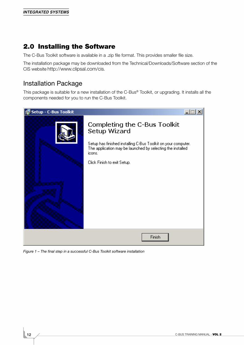
2.0 Installing the SoftwareThe C-Bus Toolkit software is available in a .zip file format. This provides smaller file size.
The installation package may be downloaded from the Technical/Downloads/Software section of the CIS website .
Installation PackageThis package is suitable for a new installation of the C-Bus® Toolkit, or upgrading. It installs all the components needed for you to run the C-Bus Toolkit.
Figure 1 – The final step in a successful C-Bus Toolkit software installation
132A. C-Bus Toolkit Software
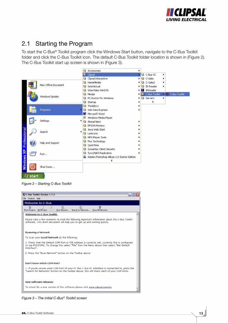
2.1 Starting the ProgramTo start the C-Bus® Toolkit program click the Windows Start button, navigate to the C-Bus Toolkit folder and click the C-Bus Toolkit icon. The default C-Bus Toolkit folder location is shown in (Figure 2). The C-Bus Toolkit start up screen is shown in (Figure 3).
Figure 2 – Starting C-Bus Toolkit
Figure 3 – The initial C-Bus® Toolkit screen
C-BUS TRAINING MANUAL - VOL 214
3.0 The Menu
3.1.1 Connect to Local RepositoryThis connects to the Toolkit database and C-Bus Networks on the local PC. This automatically occurs when starting the Toolkit software.
3.1.2 Disconnect Project RepositoryUse this to disconnect from the local or remote database and C-Bus Network so you can connect to another location.
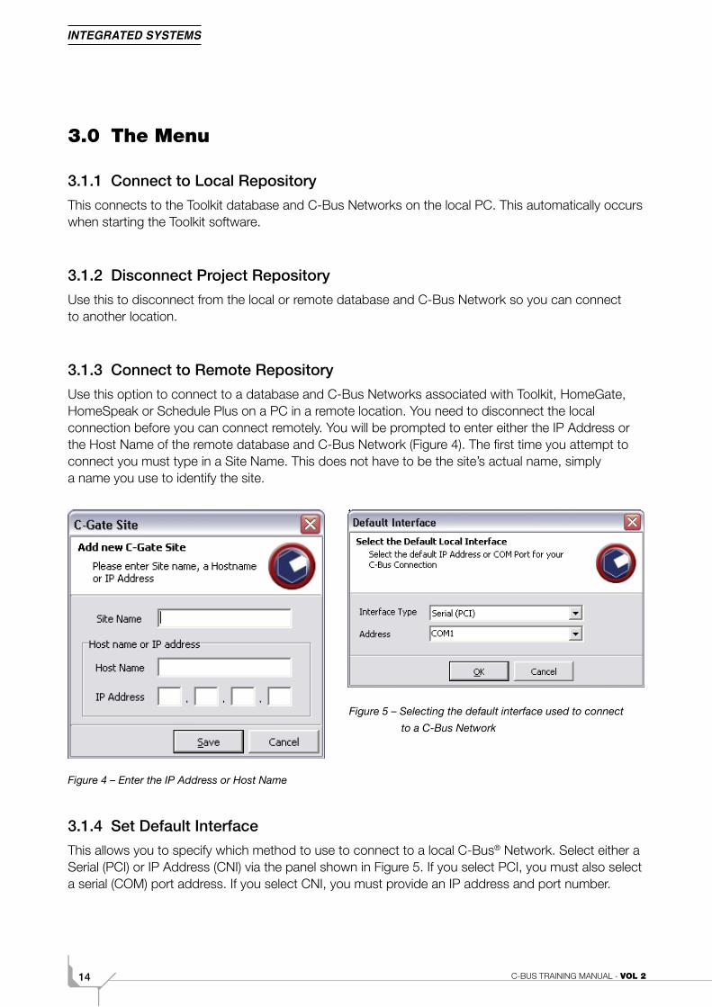
3.1.3 Connect to Remote RepositoryUse this option to connect to a database and C-Bus Networks associated with Toolkit, HomeGate, HomeSpeak or Schedule Plus on a PC in a remote location. You need to disconnect the local connection before you can connect remotely. You will be prompted to enter either the IP Address or the Host Name of the remote database and C-Bus Network (Figure 4). The first time you attempt to connect you must type in a Site Name. This does not have to be the site’s actual name, simply a name you use to identify the site.
Figure 4 – Enter the IP Address or Host Name
3.1.4 Set Default InterfaceThis allows you to specify which method to use to connect to a local C-Bus® Network. Select either a Serial (PCI) or IP Address (CNI) via the panel shown in Figure 5. If you select PCI, you must also select a serial (COM) port address. If you select CNI, you must provide an IP address and port number.
Figure 5 – Selecting the default interface used to connect
to a C-Bus Network
152A. C-Bus Toolkit Software
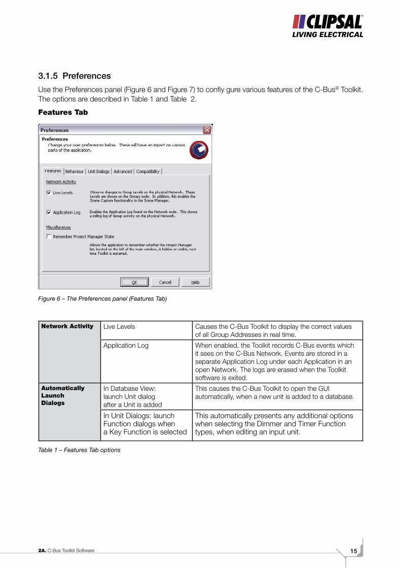
3.1.5 PreferencesUse the Preferences panel (Figure 6 and Figure 7) to confiy gure various features of the C-Bus® Toolkit. The options are described in Table 1 and Table 2.
Features Tab
Figure 6 – The Preferences panel (Features Tab)
Network Activity Live Levels Causes the C-Bus Toolkit to display the correct values of all Group Addresses in real time.
Application Log When enabled, the Toolkit records C-Bus events which it sees on the C-Bus Network. Events are stored in a separate Application Log under each Application in an open Network. The logs are erased when the Toolkit software is exited.
Automatically Launch Dialogs
In Database View: launch Unit dialog after a Unit is added
This causes the C-Bus Toolkit to open the GUI automatically, when a new unit is added to a database.
In Unit Dialogs: launch Function dialogs when a Key Function is selected
This automatically presents any additional options when selecting the Dimmer and Timer Function types, when editing an input unit.
Table 1 – Features Tab options
C-BUS TRAINING MANUAL - VOL 216
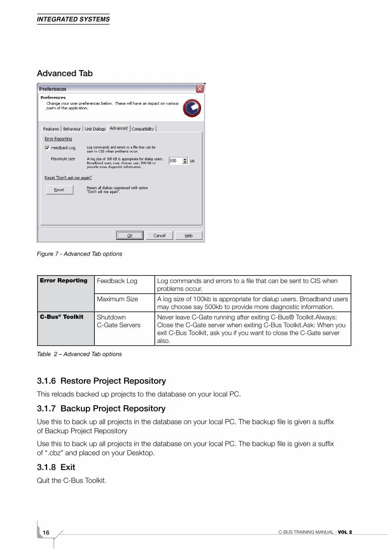
Advanced Tab
Figure 7 - Advanced Tab options
Error Reporting Feedback Log Log commands and errors to a file that can be sent to CIS when problems occur.
Maximum Size A log size of 100kb is appropriate for dialup users. Broadband users may choose say 500kb to provide more diagnostic information.
C-Bus® Toolkit Shutdown C-Gate Servers
Never leave C-Gate running after exiting C-Bus® Toolkit.Always: Close the C-Gate server when exiting C-Bus Toolkit.Ask: When you exit C-Bus Toolkit, ask you if you want to close the C-Gate server also.
Table 2 – Advanced Tab options
3.1.6 Restore Project RepositoryThis reloads backed up projects to the database on your local PC.
3.1.7 Backup Project RepositoryUse this to back up all projects in the database on your local PC. The backup file is given a suffix of Backup Project Repository
Use this to back up all projects in the database on your local PC. The backup file is given a suffix of “.cbz” and placed on your Desktop.
3.1.8 ExitQuit the C-Bus Toolkit.
172A. C-Bus Toolkit Software
3.2 Projects Menu3.2.1 Add ProjectCreate a new empty C-Bus® project. You will be asked if you 'want to add a Network to the new project'. If you answer yes, you will be prompted to provide a name for the Network, and to specify the Network connection details.
3.2.2 Scan NetworkPerform a live scan of the local Network using the default interface.
3.2.3 Search for NetworksUse this to find every interface which is connected to your PC via a PC Interface (PCI) or Computer Network Interface (CNI). Once an interface is detected, the C-Bus Toolkit allow you to scan the local Network.
3.2.4 Import ProjectsUse this option to import projects from a C-Bus V2 software installation which exists in the default location on the same PC as the C-Bus Toolkit. Imported projects are converted to C-Bus Toolkit format.
3.2.5 Export ProjectsUse this option to export projects from in a format compatible with the C-Bus V2 Installation Software. Projects are typically exported to C:\Clipsal\CBUSV2\PROJECTS on your PC.
3.2.6 Close All NetworksCloses all open Networks regardless of which project is selected.
3.2.7 Restore ProjectRestores project from project backup files (*.cb3).
3.3 Help MenuProvides information on which version of C-Bus Toolkit and C-Gate is used.
The help menu will be expanded in future releases of Toolkit software.
If required, the Clipsal Integrated Systems Technical Support line is available between the hours of 7:00AM and 6:00PM (GMT +9.30).
The C-Bus Forum is also a valuable source of information, available to all at no charge, where you can discuss products and programming issues with other C-Bus programmers. The web address is:
C-BUS TRAINING MANUAL - VOL 218
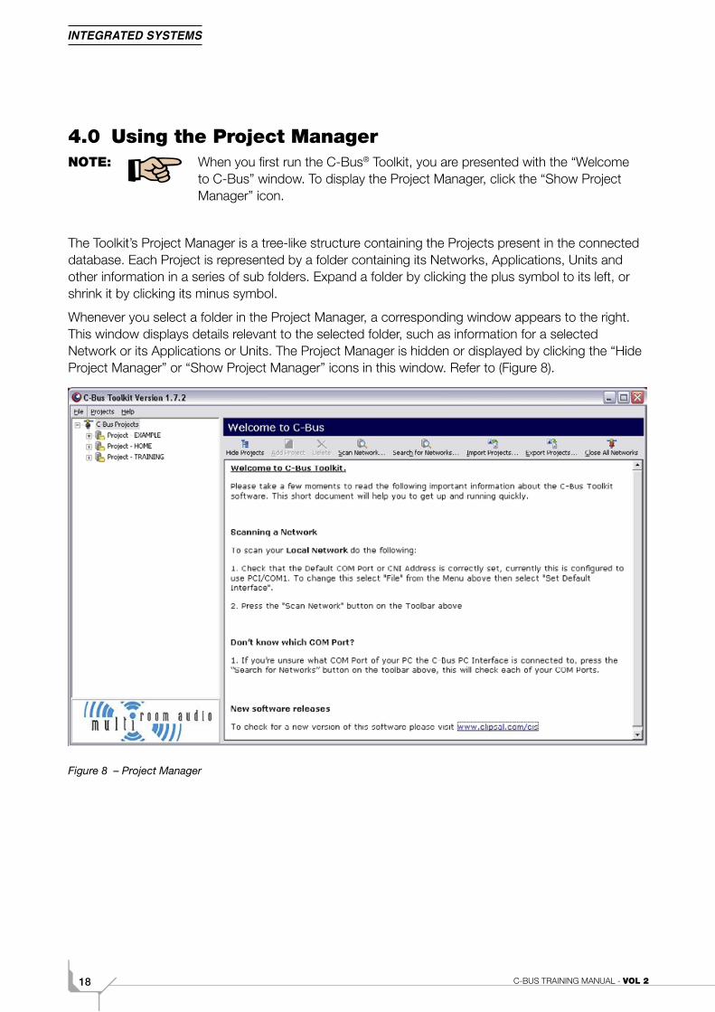
4.0 Using the Project ManagerNOTE: When you first run the C-Bus® Toolkit, you are presented with the “Welcome
to C-Bus” window. To display the Project Manager, click the “Show Project Manager” icon.
The Toolkit’s Project Manager is a tree-like structure containing the Projects present in the connected database. Each Project is represented by a folder containing its Networks, Applications, Units and other information in a series of sub folders. Expand a folder by clicking the plus symbol to its left, or shrink it by clicking its minus symbol.
Whenever you select a folder in the Project Manager, a corresponding window appears to the right. This window displays details relevant to the selected folder, such as information for a selected Network or its Applications or Units. The Project Manager is hidden or displayed by clicking the “Hide Project Manager” or “Show Project Manager” icons in this window. Refer to (Figure 8).
Figure 8 – Project Manager
192A. C-Bus Toolkit Software
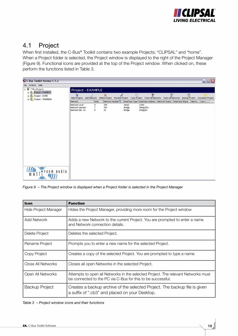
4.1 ProjectWhen first installed, the C-Bus® Toolkit contains two example Projects; “CLIPSAL” and “home”. When a Project folder is selected, the Project window is displayed to the right of the Project Manager (Figure 9). Functional icons are provided at the top of the Project window. When clicked on, these perform the functions listed in Table 3.
Figure 9 – The Project window is displayed when a Project folder is selected in the Project Manager
Icon Function
Hide Project Manager Hides the Project Manager, providing more room for the Project window
Add Network Adds a new Network to the current Project. You are prompted to enter a name and Network connection details.
Delete Project Deletes the selected Project.
Rename Project Prompts you to enter a new name for the selected Project.
Copy Project Creates a copy of the selected Project. You are prompted to type a name.
Close All Networks Closes all open Networks in the selected Project.
Open All Networks Attempts to open all Networks in the selected Project. The relevant Networks must be connected to the PC via C-Bus for this to be successful.
Backup Project Creates a backup archive of the selected Project. The backup file is given a suffix of “.cb3” and placed on your Desktop.
Table 3 – Project window icons and their functions
C-BUS TRAINING MANUAL - VOL 220
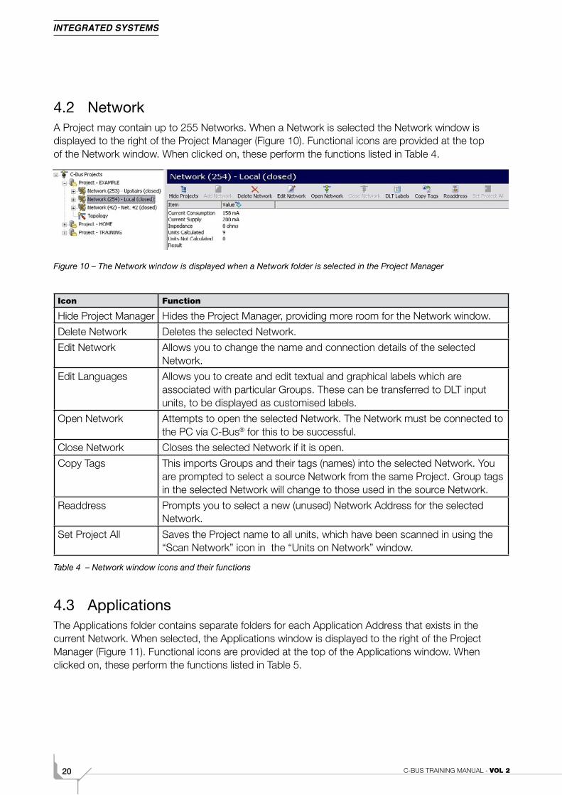
4.2 NetworkA Project may contain up to 255 Networks. When a Network is selected the Network window is displayed to the right of the Project Manager (Figure 10). Functional icons are provided at the top of the Network window. When clicked on, these perform the functions listed in Table 4.
Figure 10 – The Network window is displayed when a Network folder is selected in the Project Manager
Icon Function
Hide Project Manager Hides the Project Manager, providing more room for the Network window.
Delete Network Deletes the selected Network.
Edit Network Allows you to change the name and connection details of the selected Network.
Edit Languages Allows you to create and edit textual and graphical labels which are associated with particular Groups. These can be transferred to DLT input units, to be displayed as customised labels.
Open Network Attempts to open the selected Network. The Network must be connected to the PC via C-Bus® for this to be successful.
Close Network Closes the selected Network if it is open.
Copy Tags This imports Groups and their tags (names) into the selected Network. You are prompted to select a source Network from the same Project. Group tags in the selected Network will change to those used in the source Network.
Readdress Prompts you to select a new (unused) Network Address for the selected Network.
Set Project All Saves the Project name to all units, which have been scanned in using the “Scan Network” icon in the “Units on Network” window.
Table 4 – Network window icons and their functions
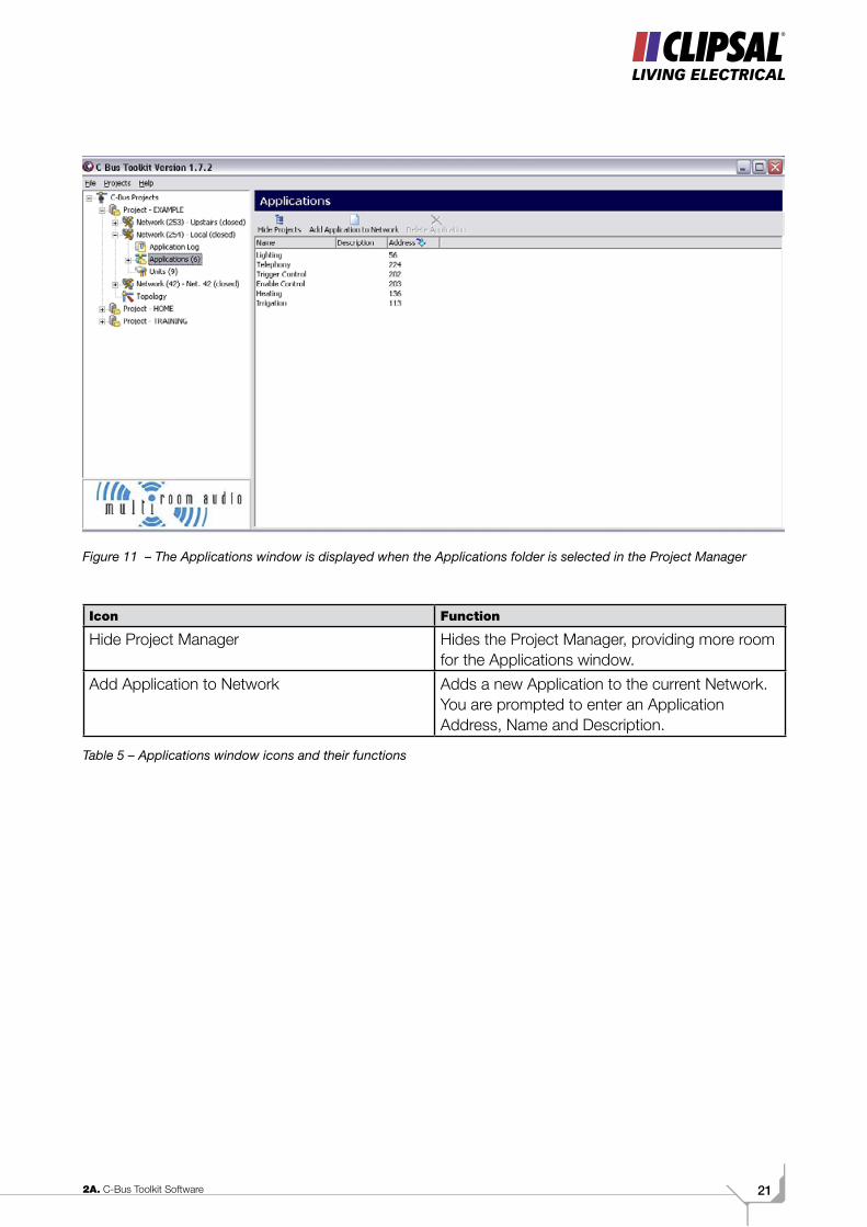
4.3 ApplicationsThe Applications folder contains separate folders for each Application Address that exists in the current Network. When selected, the Applications window is displayed to the right of the Project Manager (Figure 11). Functional icons are provided at the top of the Applications window. When clicked on, these perform the functions listed in Table 5.
212A. C-Bus Toolkit Software
Figure 11 – The Applications window is displayed when the Applications folder is selected in the Project Manager
Icon Function
Hide Project Manager Hides the Project Manager, providing more room for the Applications window.
Add Application to Network Adds a new Application to the current Network. You are prompted to enter an Application Address, Name and Description.
Table 5 – Applications window icons and their functions
C-BUS TRAINING MANUAL - VOL 222
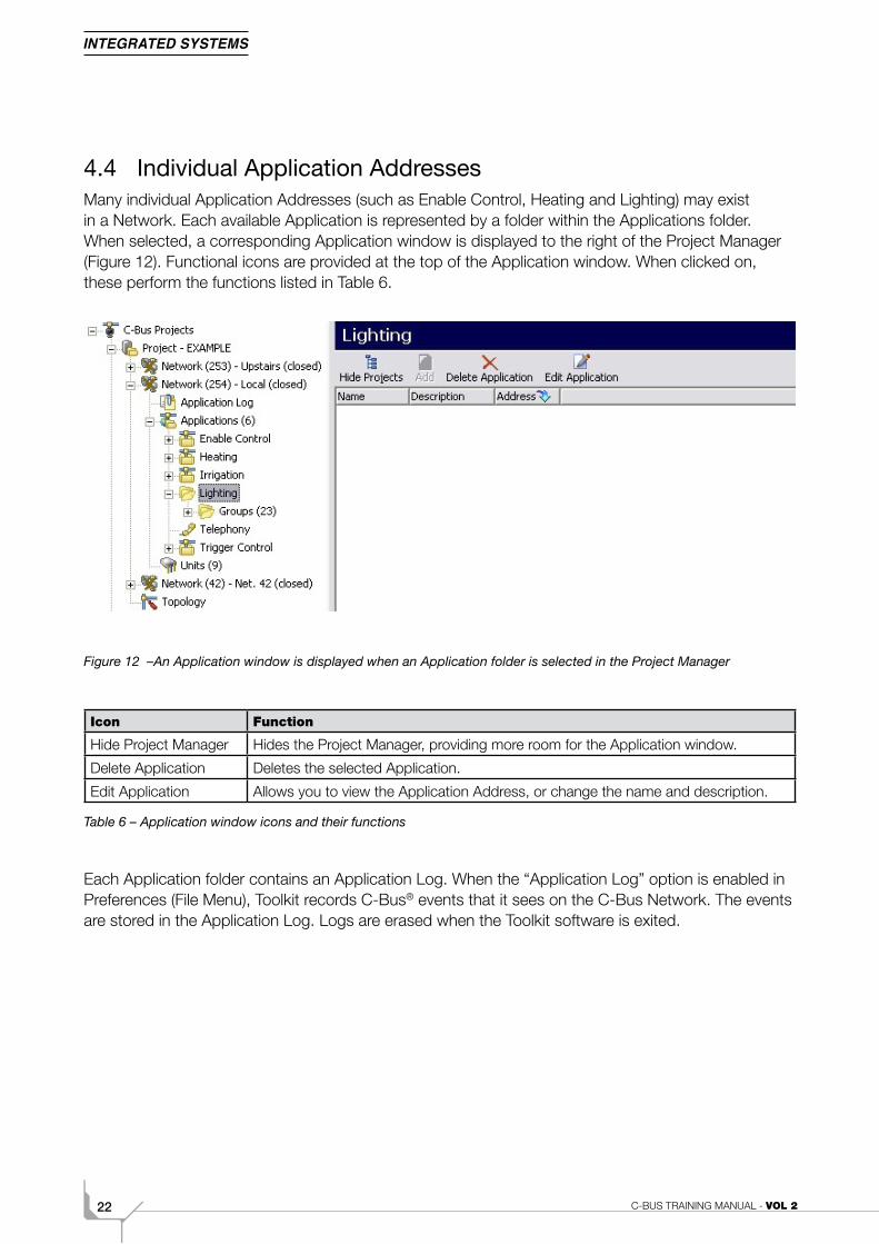
4.4 Individual Application AddressesMany individual Application Addresses (such as Enable Control, Heating and Lighting) may exist in a Network. Each available Application is represented by a folder within the Applications folder. When selected, a corresponding Application window is displayed to the right of the Project Manager (Figure 12). Functional icons are provided at the top of the Application window. When clicked on, these perform the functions listed in Table 6.
Figure 12 –An Application window is displayed when an Application folder is selected in the Project Manager
Icon Function
Hide Project Manager Hides the Project Manager, providing more room for the Application window.
Delete Application Deletes the selected Application.
Edit Application Allows you to view the Application Address, or change the name and description.
Table 6 – Application window icons and their functions
Each Application folder contains an Application Log. When the “Application Log” option is enabled in Preferences (File Menu), Toolkit records C-Bus® events that it sees on the C-Bus Network. The events are stored in the Application Log. Logs are erased when the Toolkit software is exited.
232A. C-Bus Toolkit Software
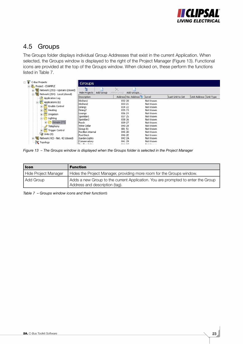
4.5 GroupsThe Groups folder displays individual Group Addresses that exist in the current Application. When selected, the Groups window is displayed to the right of the Project Manager (Figure 13). Functional icons are provided at the top of the Groups window. When clicked on, these perform the functions listed in Table 7.
Figure 13 – The Groups window is displayed when the Groups folder is selected in the Project Manager
Icon Function
Hide Project Manager Hides the Project Manager, providing more room for the Groups window.
Add Group Adds a new Group to the current Application. You are prompted to enter the Group Address and description (tag).
Table 7 – Groups window icons and their functions
C-BUS TRAINING MANUAL - VOL 224
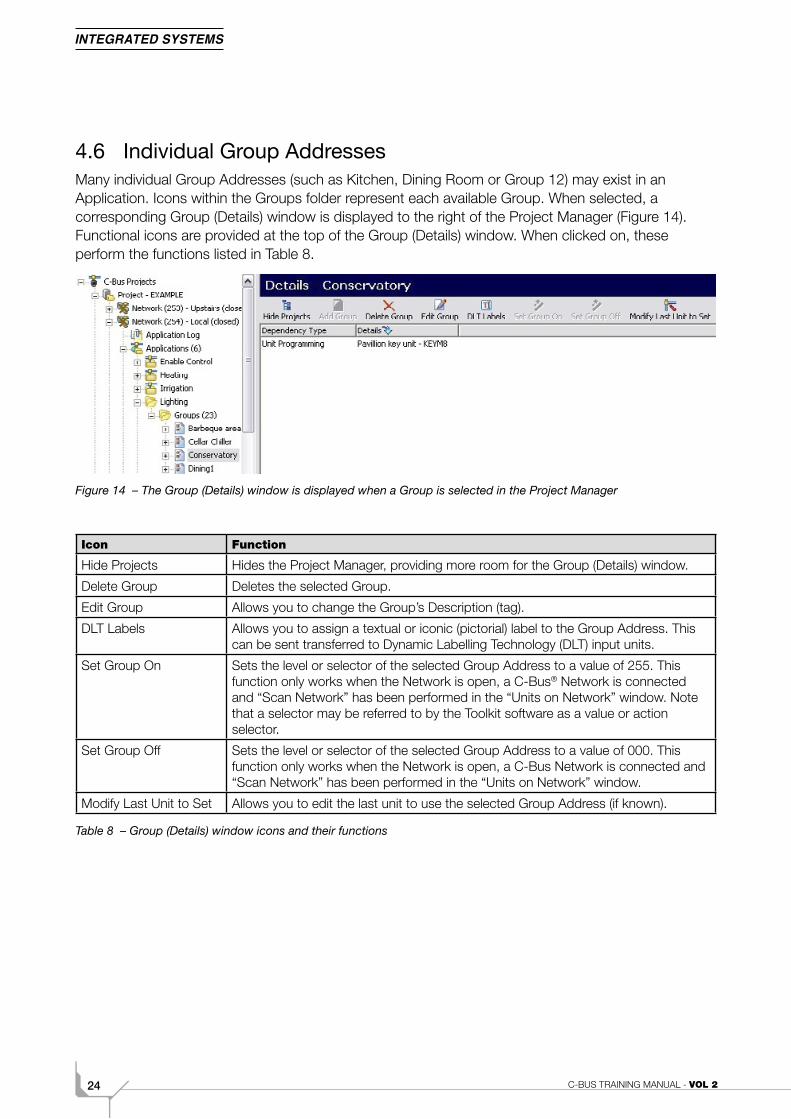
4.6 Individual Group AddressesMany individual Group Addresses (such as Kitchen, Dining Room or Group 12) may exist in an Application. Icons within the Groups folder represent each available Group. When selected, a corresponding Group (Details) window is displayed to the right of the Project Manager (Figure 14). Functional icons are provided at the top of the Group (Details) window. When clicked on, these perform the functions listed in Table 8.
Figure 14 – The Group (Details) window is displayed when a Group is selected in the Project Manager
Icon Function
Hide Projects Hides the Project Manager, providing more room for the Group (Details) window.
Delete Group Deletes the selected Group.
Edit Group Allows you to change the Group’s Description (tag).
DLT Labels Allows you to assign a textual or iconic (pictorial) label to the Group Address. This can be sent transferred to Dynamic Labelling Technology (DLT) input units.
Set Group On Sets the level or selector of the selected Group Address to a value of 255. This function only works when the Network is open, a C-Bus® Network is connected and “Scan Network” has been performed in the “Units on Network” window. Note that a selector may be referred to by the Toolkit software as a value or action selector.
Set Group Off Sets the level or selector of the selected Group Address to a value of 000. This function only works when the Network is open, a C-Bus Network is connected and “Scan Network” has been performed in the “Units on Network” window.
Modify Last Unit to Set Allows you to edit the last unit to use the selected Group Address (if known).
Table 8 – Group (Details) window icons and their functions
252A. C-Bus Toolkit Software
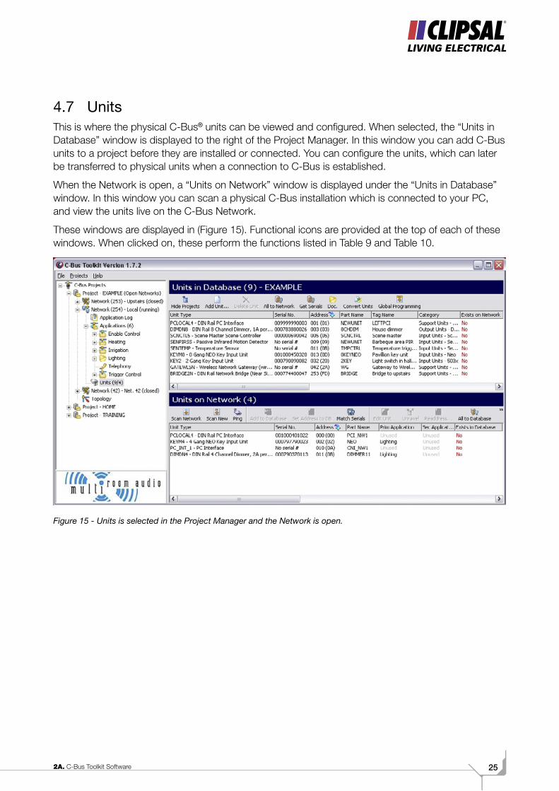
4.7 UnitsThis is where the physical C-Bus® units can be viewed and configured. When selected, the “Units in Database” window is displayed to the right of the Project Manager. In this window you can add C-Bus units to a project before they are installed or connected. You can configure the units, which can later be transferred to physical units when a connection to C-Bus is established.
When the Network is open, a “Units on Network” window is displayed under the “Units in Database” window. In this window you can scan a physical C-Bus installation which is connected to your PC, and view the units live on the C-Bus Network.
These windows are displayed in (Figure 15). Functional icons are provided at the top of each of these windows. When clicked on, these perform the functions listed in Table 9 and Table 10.
Figure 15 - Units is selected in the Project Manager and the Network is open.
C-BUS TRAINING MANUAL - VOL 226
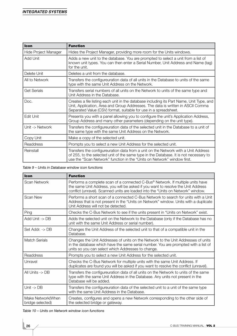
Icon Function
Hide Project Manager Hides the Project Manager, providing more room for the Units windows.
Add Unit Adds a new unit to the database. You are prompted to select a unit from a list of known unit types. You can then enter a Serial Number, Unit Address and Name (tag) for the unit.
Delete Unit Deletes a unit from the database.
All to Network Transfers the configureuration data of all units in the Database to units of the same type with the same Unit Address on the Network.
Get Serials Transfers serial numbers of all units on the Network to units of the same type and Unit Address in the Database.
Doc. Creates a file listing each unit in the database including its Part Name, Unit Type, and Unit, Application, Area and Group Addresses. The data is written in ASCII Comma Separated Value (CSV) format, suitable for use in a spreadsheet.
Edit Unit Presents you with a panel allowing you to configure the unit’s Application Address, Group Address and many other parameters (depending on the unit type).
Unit -> Network Transfers the configureuration data of the selected unit in the Database to a unit of the same type with the same Unit Address on the Network.
Copy Unit Make a copy of the selected unit.
Readdress Prompts you to select a new Unit Address for the selected unit.
Reinstall Transfers the configureuration data from a unit on the Network with a Unit Address of 255, to the selected unit of the same type in the Database. It is not necessary to use the “Scan Network” function in the “Units on Network” window first.
Table 9 – Units in Database window icon functions
Icon Function
Scan Network Performs a complete scan of a connected C-Bus® Network. If multiple units have the same Unit Address, you will be asked if you want to resolve the Unit Address conflict (unravel). Scanned units are loaded into the “Units on Network” window.
Scan New Performs a short scan of a connected C-Bus Network to search for units with a Unit Address that is not present in the “Units on Network” window. Units with a duplicate Unit Address will not be detected.
Ping Checks the C-Bus Network to see if the units present in “Units on Network” exist.
Add Unit -> DB Adds the selected unit on the Network to the Database (only if the Database has no unit with the same Unit Address or serial number).
Set Addr. -> DB Changes the Unit Address of the selected unit to that of a compatible unit in the Database.
Match Serials Changes the Unit Addresses of units on the Network to the Unit Addresses of units in the database which have the same serial number. You are prompted with a list of units so you can select which Addresses to change.
Readdress Prompts you to select a new Unit Address for the selected unit.
Unravel Checks the C-Bus Network for multiple units with the same Unit Address. If duplicates are found you will be asked if you want to resolve the conflict (unravel).
All Units -> DB Transfers the configureuration data of all units on the Network to units of the same type with the same Unit Address in the Database. Any units not present in the Database will be added.
Unit -> DB Transfers the configureuration data of the selected unit to a unit of the same type with the same Unit Address in the Database.
Make Network(When bridge selected)
Creates, configures and opens a new Network corresponding to the other side of the selected bridge or gateway.
Table 10 – Units on Network window icon functions
272A. C-Bus Toolkit Software
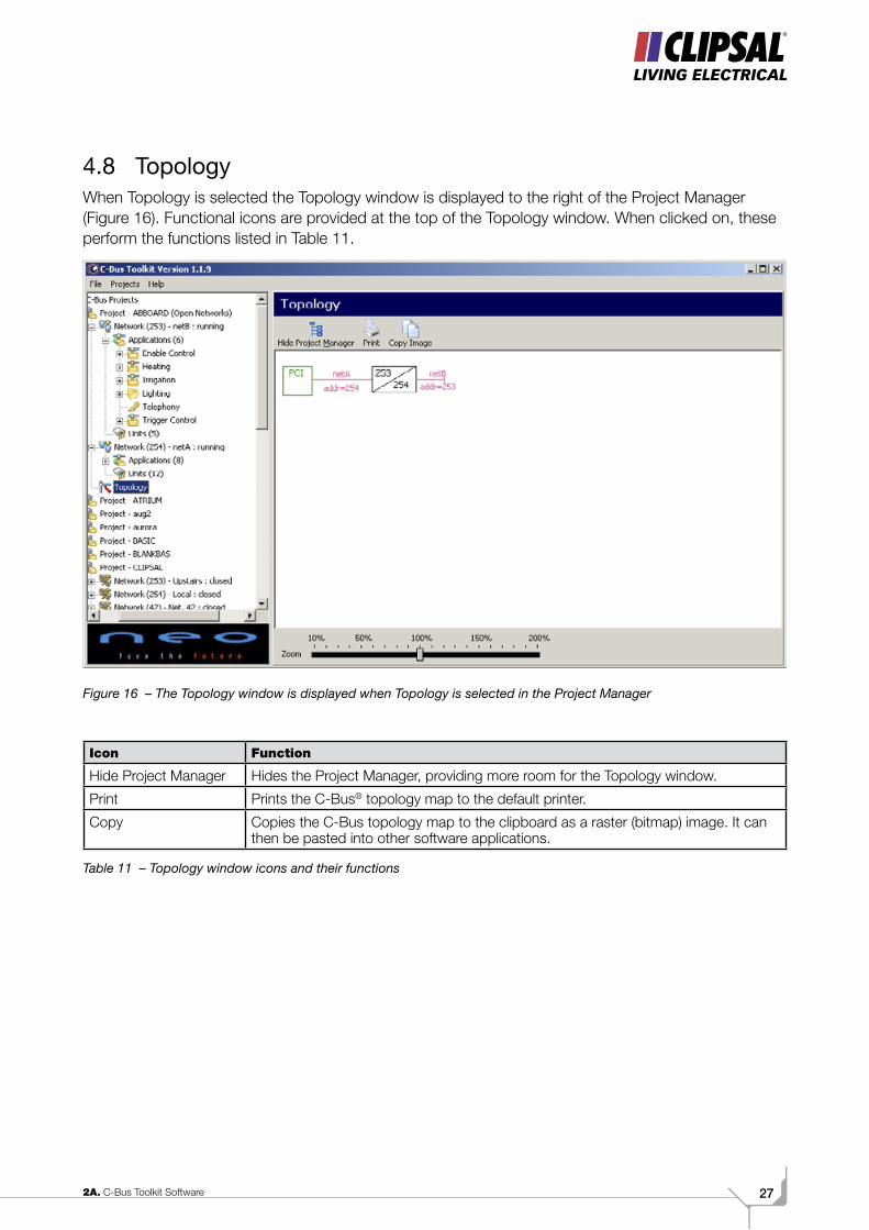
4.8 TopologyWhen Topology is selected the Topology window is displayed to the right of the Project Manager (Figure 16). Functional icons are provided at the top of the Topology window. When clicked on, these perform the functions listed in Table 11.
Figure 16 – The Topology window is displayed when Topology is selected in the Project Manager
Icon Function
Hide Project Manager Hides the Project Manager, providing more room for the Topology window.
Print Prints the C-Bus® topology map to the default printer.
Copy Copies the C-Bus topology map to the clipboard as a raster (bitmap) image. It can then be pasted into other software applications.
Table 11 – Topology window icons and their functions
C-BUS TRAINING MANUAL - VOL 228
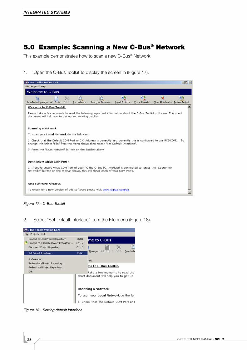
5.0 Example: Scanning a New C-Bus® NetworkThis example demonstrates how to scan a new C-Bus® Network.
1. Open the C-Bus Toolkit to display the screen in (Figure 17).
Figure 17 - C-Bus Toolkit
2. Select “Set Default Interface” from the File menu (Figure 18).
Figure 18 - Setting default interface
292A. C-Bus Toolkit Software
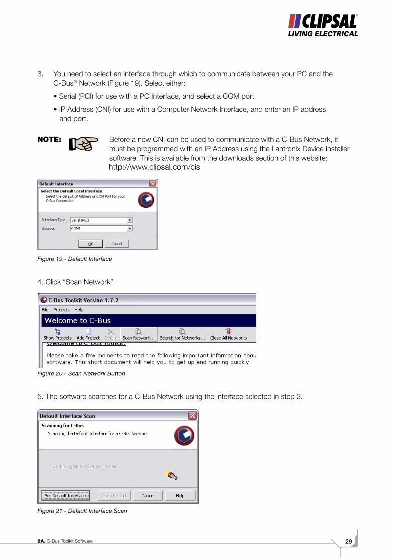
3. You need to select an interface through which to communicate between your PC and the C-Bus® Network (Figure 19). Select either:
• Serial (PCI) for use with a PC Interface, and select a COM port
• IP Address (CNI) for use with a Computer Network Interface, and enter an IP address and port.
NOTE: Before a new CNI can be used to communicate with a C-Bus Network, it must be programmed with an IP Address using the Lantronix Device Installer software. This is available from the downloads section of this website:
Figure 19 - Default Interface
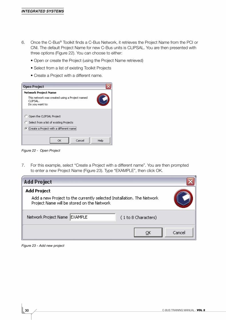
4. Click “Scan Network”
Figure 20 - Scan Network Button
5. The software searches for a C-Bus Network using the interface selected in step 3.
Figure 21 - Default Interface Scan
C-BUS TRAINING MANUAL - VOL 230
6. Once the C-Bus® Toolkit finds a C-Bus Network, it retrieves the Project Name from the PCI or CNI. The default Project Name for new C-Bus units is CLIPSAL. You are then presented with three options (Figure 22). You can choose to either:
• Open or create the Project (using the Project Name retrieved)
• Select from a list of existing Toolkit Projects
• Create a Project with a different name.
Figure 22 - Open Project
7. For this example, select “Create a Project with a different name”. You are then prompted to enter a new Project Name (Figure 23). Type “EXAMPLE”, then click OK.
Figure 23 - Add new project
312A. C-Bus Toolkit Software
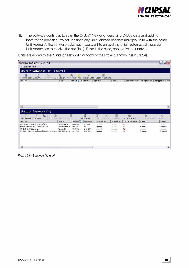
8. The software continues to scan the C-Bus® Network, identifying C-Bus units and adding them to the specified Project. If it finds any Unit Address conflicts (multiple units with the same Unit Address), the software asks you if you want to unravel the units (automatically reassign Unit Addresses to resolve the conflicts). If this is the case, choose Yes to unravel.
Units are added to the “Units on Network” window of the Project, shown in (Figure 24).
Figure 24 - Scanned Network
C-BUS TRAINING MANUAL - VOL 232
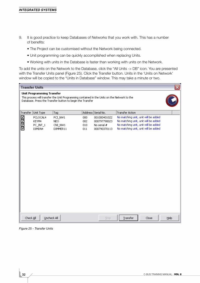
9. It is good practice to keep Databases of Networks that you work with. This has a number of benefits:
• The Project can be customised without the Network being connected.
• Unit programming can be quickly accomplished when replacing Units.
• Working with units in the Database is faster than working with units on the Network.
To add the units on the Network to the Database, click the “All Units -> DB” icon. You are presented with the Transfer Units panel (Figure 25). Click the Transfer button. Units in the 'Units on Network' window will be copied to the “Units in Database” window. This may take a minute or two.
Figure 25 - Transfer Units
332A. C-Bus Toolkit Software
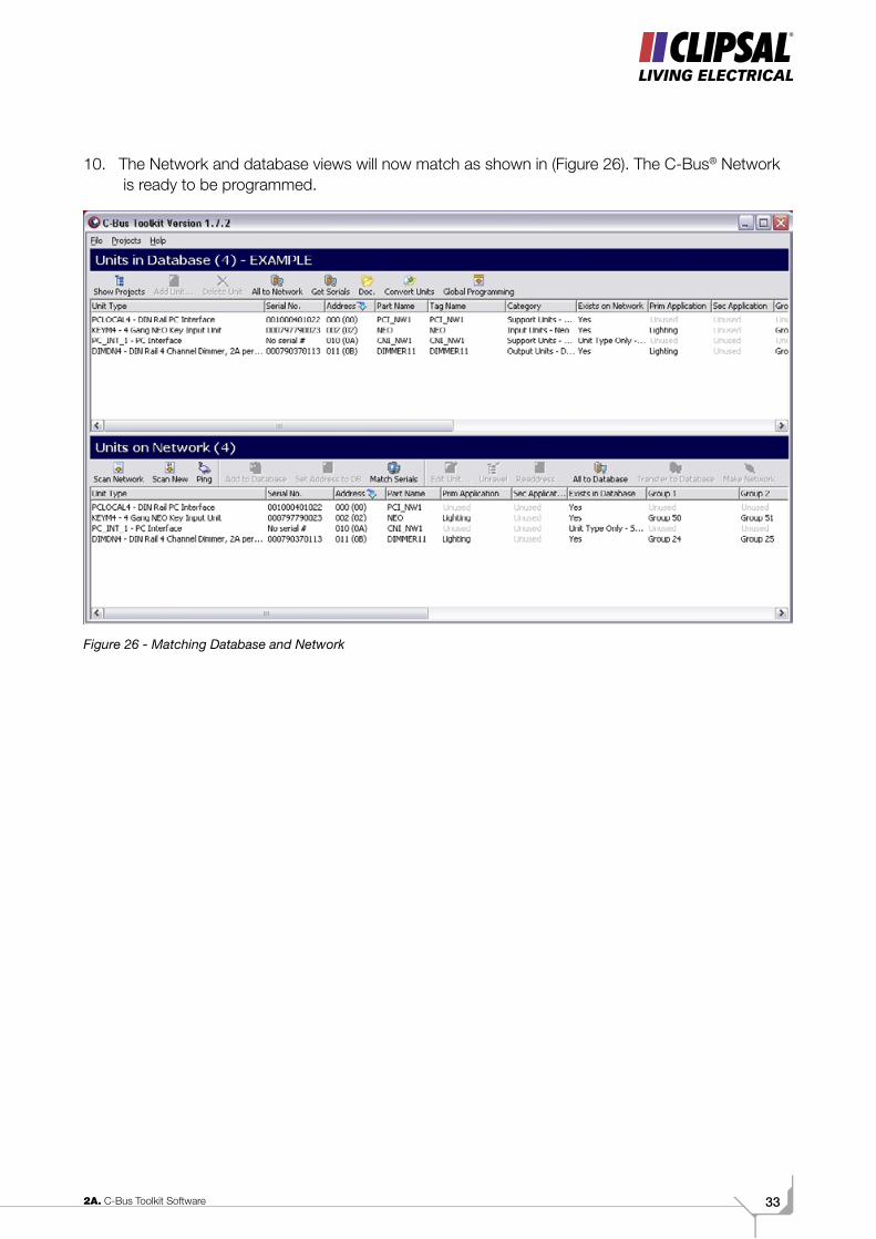
10. The Network and database views will now match as shown in (Figure 26). The C-Bus® Network is ready to be programmed.
Figure 26 - Matching Database and Network

C-BUS TRAINING MANUAL - VOL 234
Volume 2BBasic Programming
352B. Basic Programming
ScopeThis manual aims to provide an installer with the basic skills needed to program and use
C-Bus®. A fundamental technical background is required.
The manual includes basic programming information for C-Bus:
• Voltage free relays (a common output unit)
• Wall switches
• PE cell light level sensors
• PIR occupancy sensors.
It is an ideal preparation before attending the C-Bus Basic Training Course.
Learning OutcomesBy the end of this module, you should have an understanding of the basic programming options for a:
• C-Bus L5512 RVF 12 Channel Voltage Free Relay
• Standard C-Bus Wall Switch
• C-Bus Light Level Sensor
• C-Bus PIR Occupancy Sensor.
C-BUS TRAINING MANUAL - VOL 236
1.0 Basic Learn ModeThe C-Bus® 2 system features a mode, called Learn Mode, which allows Units on a C Bus Network to listen to each other and learn what they need to do by simple button presses on the Units.
To identify which are capable of entering Learn Mode check:
• Any label indicating C-Bus2
• Purple coloured case on output units.
• Orange LED’s on the input units.
The source of this new functionality is the ability to assign a load, such as a light, with a controller, such as a key input unit, by touching the two units one after the other. This is done while in a mode called “Learn Mode”, so named because the C Bus Network can now learn what the user wants to do.
NOTE: For safety reasons Learn Mode can be disabled from the C-Bus Installation Software to protect the programming of the Network.
1.0.1 Entering and Exiting Learn Mode1. Find any Learn Mode output unit.
2. Press and hold down any of the Quick Toggle buttons on any output units for 10 seconds. The Unit and C-Bus LED’s will then begin to flash alternately.
The “Unit” and “C-Bus®” indicators may initially flash together for up to 20 seconds before flashing alternately. Various Network parameters are initialised during this.
3. On any of the output units, press and hold down any of the Quick Toggle buttons for 2 seconds.
4. The Unit and C-Bus LED should now be on solid.
The C-Bus clock will then have been successfully enabled on that particular output unit. If Learn Mode has not been exited successfully within 10 minutes, all Units will resume normal operation without storing any changes.
1.0.2 Selecting Output ChannelsWhile in Learn Mode the Local Toggle buttons on Output Units can be pressed. The load will be switched on and the appropriate indicator will light up on the Output Unit. Multiple loads may be selected, across multiple Output Units. A mix of different Output Types (Dimmer and Relay) can also be selected if required.
1.0.3 Select the Output Channels required for operation.Any previously programmed associations between Input and Output Units can be overwritten by a Learn operation. To ensure this doesn’t happen, the programmer should only use each Output channel and each Input switch only ONCE when using Learn Mode.

372B. Basic Programming
1.0.4 Selecting Key InputsOnce the loads have been selected, the user may choose one or more Input Units to control those loads.
Select the Input switch(es) required to control the loads.
If you make a mistake simply press the key again to deselect it, and remove it from the current Learn operation.
The simplest association is one involving a single switch and a single load. This would be achieved by entering Learn Mode, pressing a Local Toggle button on an Output Unit (waiting to see that the indicator lights), then pressing a key on an Input Unit and exiting Learn Mode.
1.1 Learn Mode OperationsC-Bus2 Learn Mode can be used to create a wide variety of flexible control configurations. Basic On/Off switches can be configured as well as Dimmer and Timer controls.
1.1.1 Relay and Dimmer ConfigurationsThe type of control function assigned to the Input Units depends on whether you exit Learn Mode via a Relay or Dimmer Output Unit. For a switching control function, exit on a Relay Unit. For a dimmer function exit Learn Mode on a Dimmer Unit.
Key Function Exit Learn Mode Via:
Switching operation Relay Unit
Dimming operation Dimmer Unit
Other operations (eg Timer, PIR, etc) Relay OR Dimmer Unit
When the Output Unit used to exit Learn Mode is a relay then any keys included in a Learned switching (relay) operation will become on/off switches: press once and the load comes on, press again and the load goes off.
When the Output Unit used to exit Learn Mode is a dimmer then any keys selected for on/off functions in that Learn session will have dimming capability as well. Pressing the key (Short Press) toggles the light on or off. Pressing and holding the key down (Long Press) dims the light up or down with a 4 second ramp rate.
1.1.2 Multi-way Control ConfigurationsOne or more loads may be controlled from one or multiple locations by various input devices. The example below allows for two-way switching or dimming controls to be configured.
C-BUS TRAINING MANUAL - VOL 238
1.1.3 One and Two Key ConfigurationsThe single key On/Off configuration may be extended so that one key turns the load on and one turns it off. This is done during Learn Mode by pressing two adjacent keys on a single Input Unit.
After exiting from Learn Mode, the first key will turn the light on and when the second one is pressed it will turn off. When the 'on' key is pressed, the indicators on both keys will light since they are both associated with the same load. When the 'off' key is pressed, they will both go out.
Similarly, two key dimmer operation is used to separate up and down dimming operations. The first key will turn the load on (Short Press), or ramp the load upward when pressed and held (Long Press). The second key will turn the light off (Short Press), or ramp downward if pressed and held (Long Press).
If two keys are pressed on a particular input unit during the Learn operation, the last two keys pressed will become the 'On/Up' and 'Off/Down' keys respectively.
1.1.4 Area Address SwitchingArea Address switching functions are commonly required, giving the ability to provide a Master On/Off switch that turns all lights and loads on or off simultaneously. This special case occurs when all Output channels on all Output Units are selected, and then one of those Output Units is used to exit Learn Mode.
It is assumed that the primary function of the key is intended to be as a Master Off switch. Hence a Short Press of the key will instantaneously turn off all selected lights and loads. A Long Press on the key will turn them all on.
Two Key Master switch configurations are permitted, with the first key assigned the Master On function, and the second key a Master Off function.
Master Switching controls should be configured last using Learn Mode.
To implement Area Address Switching:
• Set the Network into Learn Mode
• Turn on all Local Toggle buttons
• Select a C-Bus key to control the Area Address
• Exit Learn Mode.
You can still individually control each load for any Unit which has Master Switching implemented. The individual loads must be learned first, then the Master Switch configured.
Some temporary indicator state mis-matches may occur when Units are operated in this way; however these are normally resolved automatically in seconds.
1.1.5 Timer ConfigurationsThe C-Bus2 system offers many timer options and some of these are available by means of Learn Mode. To create a timer switch once in Learn Mode, press and hold the key on an Input Unit.
The key indicator will come on after 1 second and then a series of double flashes will occur. Each double flash represents a time period of 5 minutes, with your selection being made when you release
392B. Basic Programming
the key. If the key is released before the first double flash, a 5 second timer will be set. This can be useful for testing purposes.
When a timer function has been selected the LED will give a single flash at 1 second intervals to ensure the user is aware of this function being selected for that key.
1.2 Super Learn ModeSuper Learn Mode is a powerful utility, allowing the user to:
• Reset Group Addresses on an Output Unit to $FF Unused
• Reset Area Addresses on an Output Unit to $FF Unused
• View the status of the Network Burden on an Output Unit
• Manually Enable or Disable the Network Burden on an Output Unit
1.2.1 Entering Super Learn ModeA C-Bus2 Learn capable Output Unit is placed in Super Learn Mode by double clicking an Local Toggle button whilst that Unit is in Learn Mode.
All loads and associated indicators on that Unit will come on, and the “Unit” indicator will flash rapidly. The “C-Bus” indicator then shows the state of the Burden for that Unit. If the “C-Bus” indicator is on, then the Burden is enabled, if the “C-Bus” indicator is off, then the Burden is disabled.
1.2.2 Resetting To DefaultsSuper Learn Mode may be used to clear Group Addresses from Output Units and restore other factory default settings. Upon exiting Super Learn Mode, all Group Addresses for the selected channels will be reset (cleared to $FF ‘Unused’).
When a Unit is placed in Super Learn Mode all channels on that Unit are selected by default, however individual channels may be de-selected as required. Only the selected channels will be cleared.
• If ALL channels on a C-Bus2 Output Unit are selected, then the Area Address and various other factory settings will be reset. If all channels on a Unit are not selected, the Area Address of that Unit will remain unchanged.
• Channels on all other output units may be selected (even though they are not in Super Learn Mode). So on exit of Super Learn Mode, all Quick Toggle Buttons that are on, will be set to default.
C-BUS TRAINING MANUAL - VOL 240
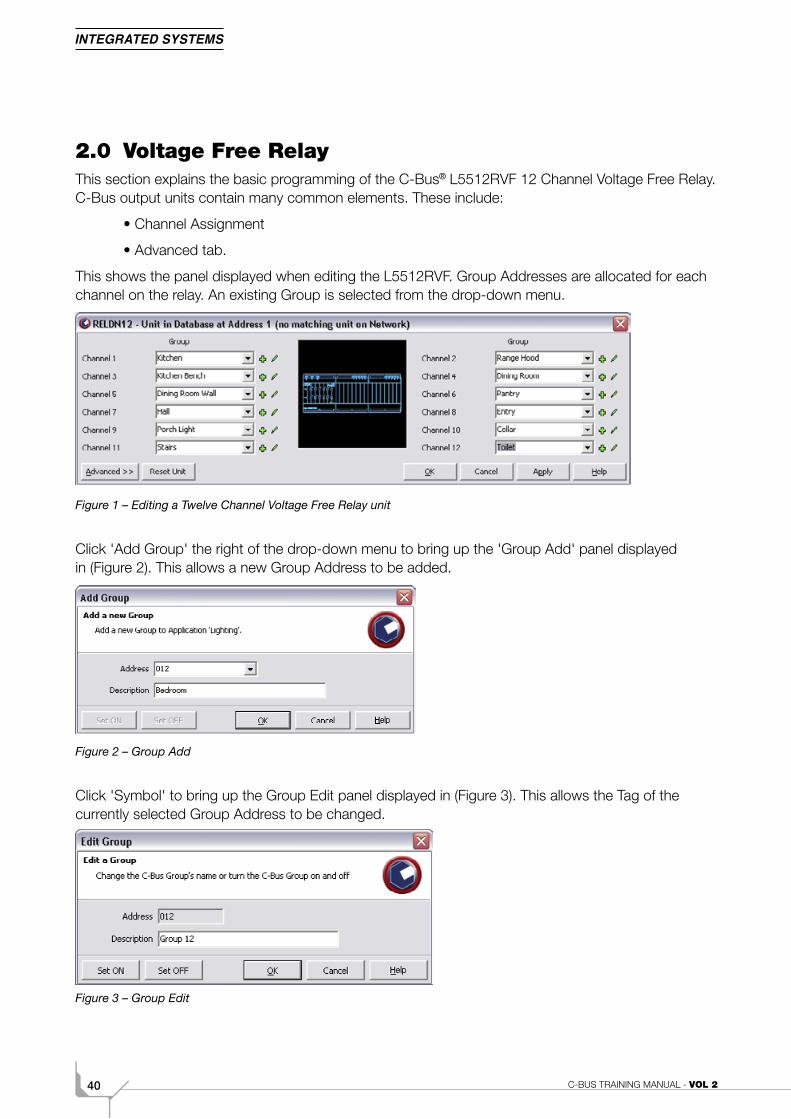
2.0 Voltage Free RelayThis section explains the basic programming of the C-Bus® L5512RVF 12 Channel Voltage Free Relay. C-Bus output units contain many common elements. These include:
• Channel Assignment
• Advanced tab.
This shows the panel displayed when editing the L5512RVF. Group Addresses are allocated for each channel on the relay. An existing Group is selected from the drop-down menu.
Figure 1 – Editing a Twelve Channel Voltage Free Relay unit
Click 'Add Group' the right of the drop-down menu to bring up the 'Group Add' panel displayed in (Figure 2). This allows a new Group Address to be added.
Figure 2 – Group Add
Click 'Symbol' to bring up the Group Edit panel displayed in (Figure 3). This allows the Tag of the currently selected Group Address to be changed.
Figure 3 – Group Edit
412B. Basic Programming
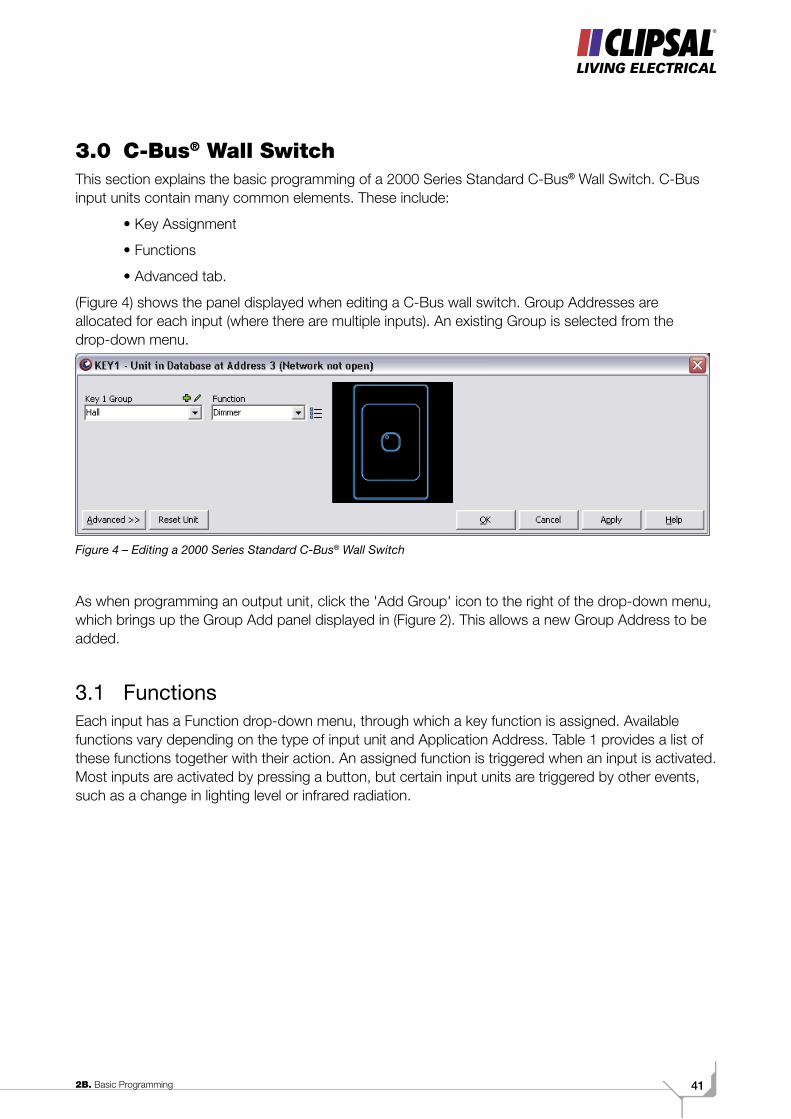
3.0 C-Bus® Wall SwitchThis section explains the basic programming of a 2000 Series Standard C-Bus® Wall Switch. C-Bus input units contain many common elements. These include:
• Key Assignment
• Functions
• Advanced tab.
(Figure 4) shows the panel displayed when editing a C-Bus wall switch. Group Addresses are allocated for each input (where there are multiple inputs). An existing Group is selected from the drop-down menu.
Figure 4 – Editing a 2000 Series Standard C-Bus® Wall Switch
As when programming an output unit, click the 'Add Group' icon to the right of the drop-down menu, which brings up the Group Add panel displayed in (Figure 2). This allows a new Group Address to be added.
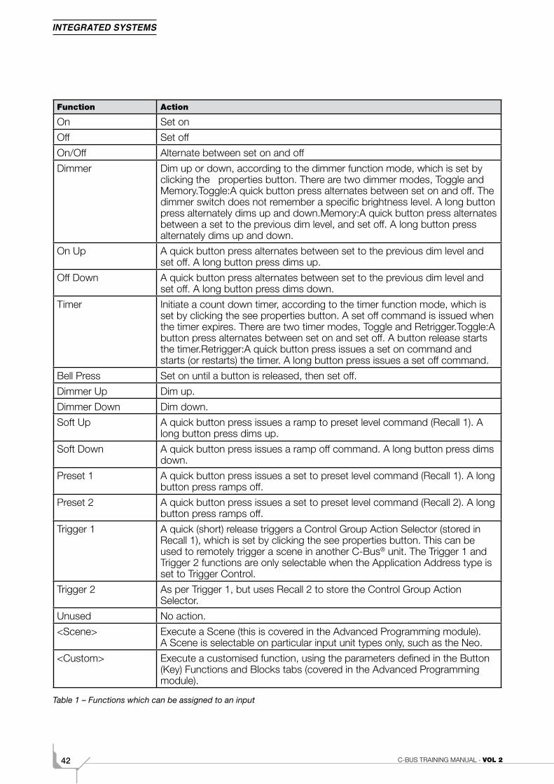
3.1 FunctionsEach input has a Function drop-down menu, through which a key function is assigned. Available functions vary depending on the type of input unit and Application Address. Table 1 provides a list of these functions together with their action. An assigned function is triggered when an input is activated. Most inputs are activated by pressing a button, but certain input units are triggered by other events, such as a change in lighting level or infrared radiation.
C-BUS TRAINING MANUAL - VOL 242
Function Action
On Set on
Off Set off
On/Off Alternate between set on and off
Dimmer Dim up or down, according to the dimmer function mode, which is set by clicking the properties button. There are two dimmer modes, Toggle and Memory.Toggle:A quick button press alternates between set on and off. The dimmer switch does not remember a specific brightness level. A long button press alternately dims up and down.Memory:A quick button press alternates between a set to the previous dim level, and set off. A long button press alternately dims up and down.
On Up A quick button press alternates between set to the previous dim level and set off. A long button press dims up.
Off Down A quick button press alternates between set to the previous dim level and set off. A long button press dims down.
Timer Initiate a count down timer, according to the timer function mode, which is set by clicking the see properties button. A set off command is issued when the timer expires. There are two timer modes, Toggle and Retrigger.Toggle:A button press alternates between set on and set off. A button release starts the timer.Retrigger:A quick button press issues a set on command and starts (or restarts) the timer. A long button press issues a set off command.
Bell Press Set on until a button is released, then set off.
Dimmer Up Dim up.
Dimmer Down Dim down.
Soft Up A quick button press issues a ramp to preset level command (Recall 1). A long button press dims up.
Soft Down A quick button press issues a ramp off command. A long button press dims down.
Preset 1 A quick button press issues a set to preset level command (Recall 1). A long button press ramps off.
Preset 2 A quick button press issues a set to preset level command (Recall 2). A long button press ramps off.
Trigger 1 A quick (short) release triggers a Control Group Action Selector (stored in Recall 1), which is set by clicking the see properties button. This can be used to remotely trigger a scene in another C-Bus® unit. The Trigger 1 and Trigger 2 functions are only selectable when the Application Address type is set to Trigger Control.
Trigger 2 As per Trigger 1, but uses Recall 2 to store the Control Group Action Selector.
Unused No action.
<Scene> Execute a Scene (this is covered in the Advanced Programming module). A Scene is selectable on particular input unit types only, such as the Neo.
<Custom> Execute a customised function, using the parameters defined in the Button (Key) Functions and Blocks tabs (covered in the Advanced Programming module).
Table 1 – Functions which can be assigned to an input
432B. Basic Programming
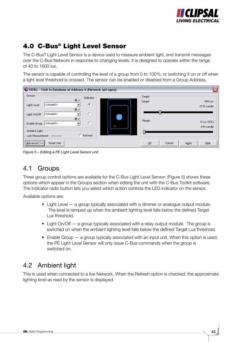
4.0 C-Bus® Light Level SensorThe C-Bus® Light Level Sensor is a device used to measure ambient light, and transmit messages over the C-Bus Network in response to changing levels. It is designed to operate within the range of 40 to 1600 lux.
The sensor is capable of controlling the level of a group from 0 to 100%, or switching it on or off when a light level threshold is crossed. The sensor can be enabled or disabled from a Group Address.
Figure 5 – Editing a PE Light Level Sensor unit
4.1 GroupsThree group control options are available for the C-Bus Light Level Sensor. (Figure 5) shows these options which appear in the Groups section when editing the unit with the C-Bus Toolkit software. The Indicator radio button lets you select which action controls the LED indicator on the sensor.
Available options are:
• Light Level — a group typically associated with a dimmer or analogue output module. The level is ramped up when the ambient lighting level falls below the defined Target Lux threshold.
• Light On/Off — a group typically associated with a relay output module. The group is switched on when the ambient lighting level falls below the defined Target Lux threshold.
• Enable Group — a group typically associated with an input unit. When this option is used, the PE Light Level Sensor will only issue C-Bus commands when the group is switched on.
4.2 Ambient lightThis is used when connected to a live Network. When the Refresh option is checked, the approximate lighting level as read by the sensor is displayed.
C-BUS TRAINING MANUAL - VOL 244
4.3 TargetThere are two values which determine the level at which the sensor responds to a change in ambient lighting levels:
• Target Lux — the threshold lux level below which any “Light Level” or “Light On/Off” group is activated. When used with dimmers you can think of this as the level of lighting that you would like to maintain.
• Margin — the level of variation from the Target Lux level at which the threshold operates. This can be used to prevent constant switching of relay levels when the ambient light level varies regularly (perhaps due to passing clouds). It means that a “Light On/Off” group can be set to turn on at a level below the Target Lux, and turn off at a level above the Target Lux.
452B. Basic Programming
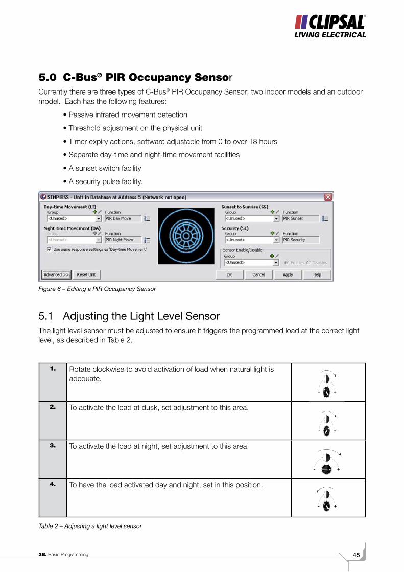
5.0 C-Bus® PIR Occupancy SensorCurrently there are three types of C-Bus® PIR Occupancy Sensor; two indoor models and an outdoor model. Each has the following features:
• Passive infrared movement detection
• Threshold adjustment on the physical unit
• Timer expiry actions, software adjustable from 0 to over 18 hours
• Separate day-time and night-time movement facilities
• A sunset switch facility
• A security pulse facility.
Figure 6 – Editing a PIR Occupancy Sensor
5.1 Adjusting the Light Level SensorThe light level sensor must be adjusted to ensure it triggers the programmed load at the correct light level, as described in Table 2.
1. Rotate clockwise to avoid activation of load when natural light is adequate.
2. To activate the load at dusk, set adjustment to this area.
3. To activate the load at night, set adjustment to this area.
4. To have the load activated day and night, set in this position.
Table 2 – Adjusting a light level sensor
- +
- +
- +
- +

C-BUS TRAINING MANUAL - VOL 246
5.2 Day Time Movement DetectionThis activates a group whenever the ambient lighting level is above the threshold set on the light level sensor, and movement is detected. The selectable group is located next to the PIR Day Move function. A timer can be used to perform an action (such as switch a group off) a definable period of time after movement is detected. Timer options can be seen in (Figure 7). They are accessed via the properties button.
Figure 7 – Timer options
5.3 Night Time Movement DetectionThis activates a group whenever the ambient lighting level is below the threshold set on the light level sensor, and movement is detected. The selectable group is located next to the PIR Night Move function. A timer can be used to perform an action (such as switch a group off) a definable period of time after movement is detected. Timer options are accessed via the properties button.
5.4 Sunset to SunriseThe PIR sensors have a PIR Sunset function, which can switch lights on at sunset. The selected group is switched off after a timer expires or sunrise, whichever occurs first. Timer options are accessed via the properties button.
5.5 Security FeaturesPIR Sensors also have a security feature which sends a short pulse intended to drive a buzzer or light to indicate movement at any time, irrespective of the light threshold.
472B. Basic Programming
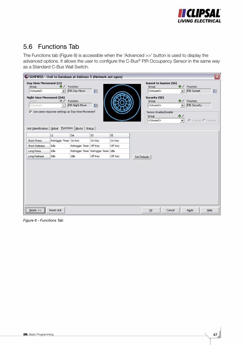
5.6 Functions TabThe Functions tab (Figure 8) is accessible when the 'Advanced >>' button is used to display the advanced options. It allows the user to configure the C-Bus® PIR Occupancy Sensor in the same way as a Standard C-Bus Wall Switch.
Figure 8 - Functions Tab
C-BUS TRAINING MANUAL - VOL 248
Volume 2CAdvanced Programming
1C. C-Bus® Hardware
492C. Advanced Programming
ScopeThis manual aims to provide an installer with the basic skills needed to program and use C-Bus®. A fundamental technical background is required.
The manual includes advanced programming information for:
• A voltage free relay (output unit)
• The Neo® (input unit)
• Scene control.
It is an ideal preparation before attending the C-Bus Basic Training Course.
Learning OutcomesBy the end of this module, you should have an understanding of:
• The C-Bus L5512RVF 12 Channel Voltage Free Relay
• The C-Bus Neo Wall Switch
• Scene control.
C-BUS TRAINING MANUAL - VOL 250
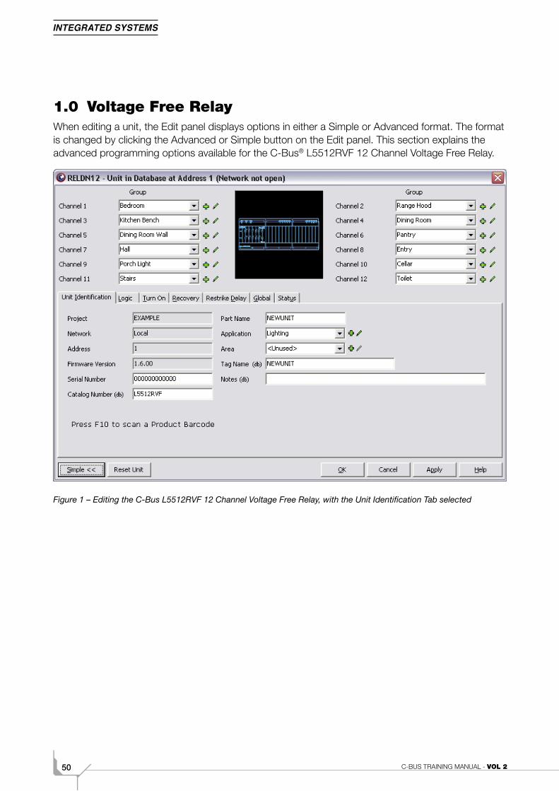
1.0 Voltage Free RelayWhen editing a unit, the Edit panel displays options in either a Simple or Advanced format. The format is changed by clicking the Advanced or Simple button on the Edit panel. This section explains the advanced programming options available for the C-Bus® L5512RVF 12 Channel Voltage Free Relay.
Figure 1 – Editing the C-Bus L5512RVF 12 Channel Voltage Free Relay, with the Unit Identification Tab selected
512C. Advanced Programming
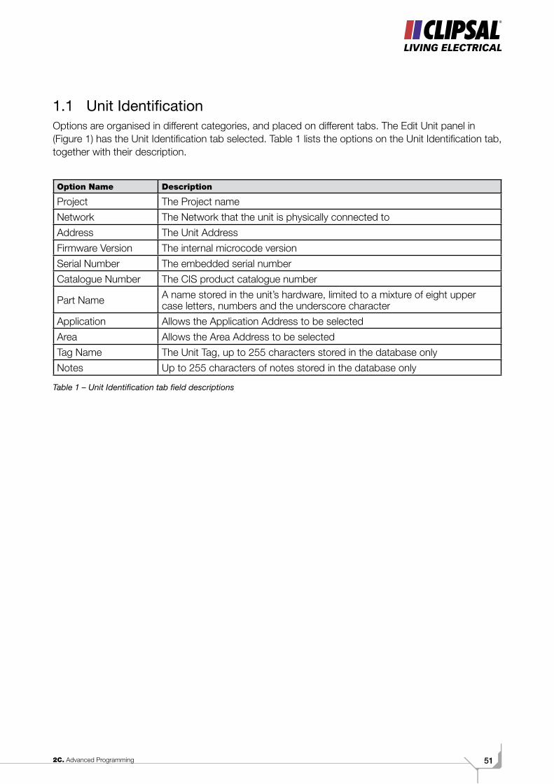
1.1 Unit IdentificationOptions are organised in different categories, and placed on different tabs. The Edit Unit panel in (Figure 1) has the Unit Identification tab selected. Table 1 lists the options on the Unit Identification tab, together with their description.
Option Name Description
Project The Project name
Network The Network that the unit is physically connected to
Address The Unit Address
Firmware Version The internal microcode version
Serial Number The embedded serial number
Catalogue Number The CIS product catalogue number
Part Name A name stored in the unit’s hardware, limited to a mixture of eight upper case letters, numbers and the underscore character
Application Allows the Application Address to be selected
Area Allows the Area Address to be selected
Tag Name The Unit Tag, up to 255 characters stored in the database only
Notes Up to 255 characters of notes stored in the database only
Table 1 – Unit Identification tab field descriptions
C-BUS TRAINING MANUAL - VOL 252
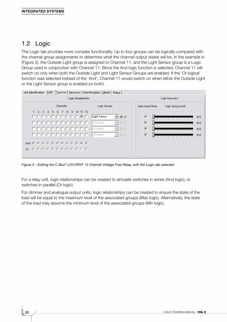
1.2 LogicThe Logic tab provides more complex functionality. Up to four groups can be logically compared with the channel group assignments to determine what the channel output states will be. In the example in (Figure 2), the Outside Light group is assigned to Channel 11, and the Light Sensor group is a Logic Group used in conjunction with Channel 11. Since the And logic function is selected, Channel 11 will switch on only when both the Outside Light and Light Sensor Groups are enabled. If the 'Or logical' function was selected instead of the 'And', Channel 11 would switch on when either the Outside Light or the Light Sensor group is enabled (or both).
Figure 2 – Editing the C-Bus® L5512RVF 12 Channel Voltage Free Relay, with the Logic tab selected
For a relay unit, logic relationships can be created to simulate switches in series (And logic), or switches in parallel (Or logic).
For dimmer and analogue output units, logic relationships can be created to ensure the state of the load will be equal to the maximum level of the associated groups (Max logic). Alternatively, the state of the load may assume the minimum level of the associated groups (Min logic).

532C. Advanced Programming
1.3 Turn OnIn relay units, the Turn On Threshold levels (Figure 3) determine the level at which output units switch on in response to their controlling group levels.
In dimmer units, the Turn On Threshold levels determine the minimum and maximum output levels which are used in response to controlling group levels. If channel 1 is set to minimum and maximum levels of 40% and 80% respectively, the output will be set to 40% in response to a controlling group level of 1%, and to 80% in response to a controlling group level of 100%.
Figure 3 – Editing the C-Bus® L5512RVF 12 Channel Voltage Free Relay, with the Turn On tab selected
Turn On Threshold is commonly used:
• To set a minimum brightness level on one or more channels
• For Light Level Sensor relay switching (sunset and switched bank dimming)
• For manual switched bank dimming
• To stagger relay switching in order to manage inrush currents across multiple circuits.
Staggered levels are set by selecting a Stagger Level percentage and pressing the Stagger button. The channel threshold level of each output is then sequentially incremented by the approximate percentage value.
1.3.1 Interlock ChannelsThis option sets the number of sequential output channels to be 'interlocked' together. When channels are interlocked, only the highest numbered interlocked channel will respond to an enabled group. For example is the Interlock value is set to 4, channels 1 to 4 will be interlocked. If the groups on channels 1 and 3 were enabled, only channel 3 would switch on. This feature could be used in motor speed control switching.
1.3.2 Synchronise SlidersWhen this option is checked, adjusting the level of any slider sets all to the same level.
C-BUS TRAINING MANUAL - VOL 254
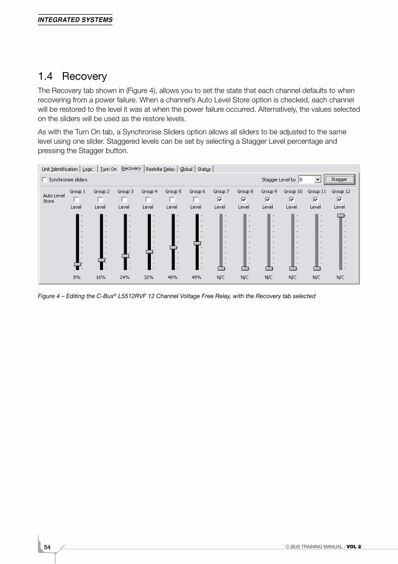
1.4 RecoveryThe Recovery tab shown in (Figure 4), allows you to set the state that each channel defaults to when recovering from a power failure. When a channel’s Auto Level Store option is checked, each channel will be restored to the level it was at when the power failure occurred. Alternatively, the values selected on the sliders will be used as the restore levels.
As with the Turn On tab, a Synchronise Sliders option allows all sliders to be adjusted to the same level using one slider. Staggered levels can be set by selecting a Stagger Level percentage and pressing the Stagger button.
Figure 4 – Editing the C-Bus® L5512RVF 12 Channel Voltage Free Relay, with the Recovery tab selected
552C. Advanced Programming
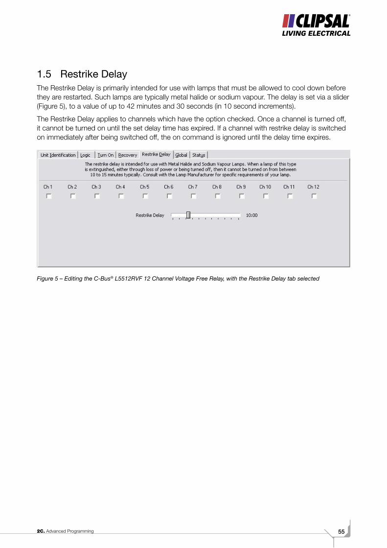
1.5 Restrike DelayThe Restrike Delay is primarily intended for use with lamps that must be allowed to cool down before they are restarted. Such lamps are typically metal halide or sodium vapour. The delay is set via a slider (Figure 5), to a value of up to 42 minutes and 30 seconds (in 10 second increments).
The Restrike Delay applies to channels which have the option checked. Once a channel is turned off, it cannot be turned on until the set delay time has expired. If a channel with restrike delay is switched on immediately after being switched off, the on command is ignored until the delay time expires.
Figure 5 – Editing the C-Bus® L5512RVF 12 Channel Voltage Free Relay, with the Restrike Delay tab selected
C-BUS TRAINING MANUAL - VOL 256
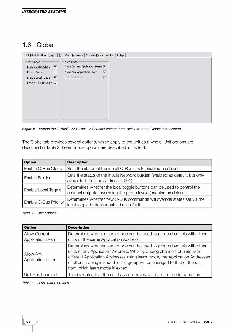
1.6 Global
Figure 6 – Editing the C-Bus® L5512RVF 12 Channel Voltage Free Relay, with the Global tab selected
The Global tab provides several options, which apply to the unit as a whole. Unit options are described in Table 2. Learn mode options are described in Table 3.
Option Description
Enable C-Bus Clock Sets the status of the inbuilt C-Bus clock (enabled as default).
Enable BurdenSets the status of the inbuilt Network burden (enabled as default, but only available if the Unit Address is 001).
Enable Local ToggleDetermines whether the local toggle buttons can be used to control the channel outputs, overriding the group levels (enabled as default).
Enable C-Bus PriorityDetermines whether new C-Bus commands will override states set via the local toggle buttons (enabled as default).
Table 2 – Unit options
Option Description
Allow Current Application Learn
Determines whether learn mode can be used to group channels with other units of the same Application Address.
Allow Any Application Learn
Determines whether learn mode can be used to group channels with other units of any Application Address. When grouping channels of units with different Application Addresses using learn mode, the Application Addresses of all units being included in the group will be changed to that of the unit from which learn mode is exited.
Unit Has Learned This indicates that the unit has been involved in a learn mode operation.
Table 3 – Learn mode options
572C. Advanced Programming
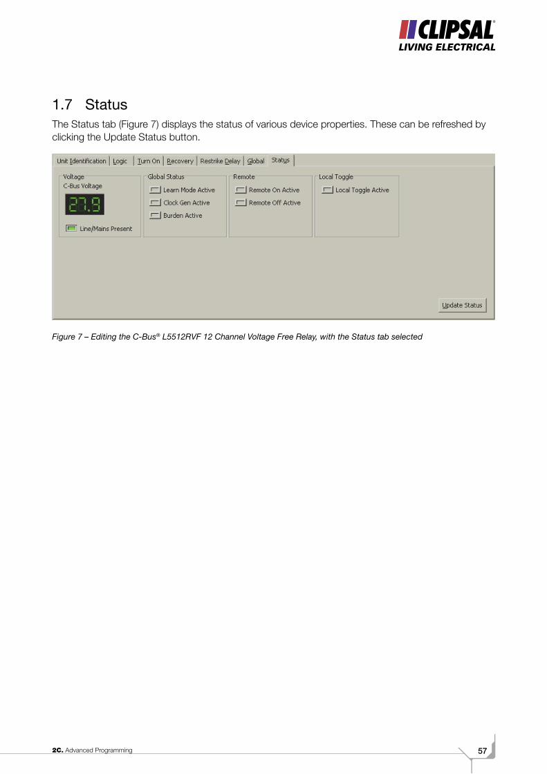
1.7 StatusThe Status tab (Figure 7) displays the status of various device properties. These can be refreshed by clicking the Update Status button.
Figure 7 – Editing the C-Bus® L5512RVF 12 Channel Voltage Free Relay, with the Status tab selected
C-BUS TRAINING MANUAL - VOL 258
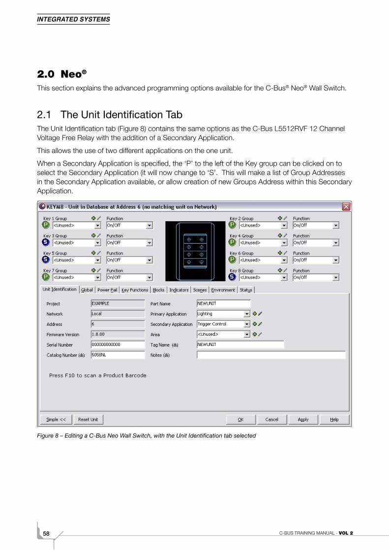
2.0 Neo®
This section explains the advanced programming options available for the C-Bus® Neo® Wall Switch.
2.1 The Unit Identification TabThe Unit Identification tab (Figure 8) contains the same options as the C-Bus L5512RVF 12 Channel Voltage Free Relay with the addition of a Secondary Application.
This allows the use of two different applications on the one unit.
When a Secondary Application is specified, the ‘P’ to the left of the Key group can be clicked on to select the Secondary Application (it will now change to ‘S’. This will make a list of Group Addresses in the Secondary Application available, or allow creation of new Groups Address within this Secondary Application.
Figure 8 – Editing a C-Bus Neo Wall Switch, with the Unit Identification tab selected
592C. Advanced Programming
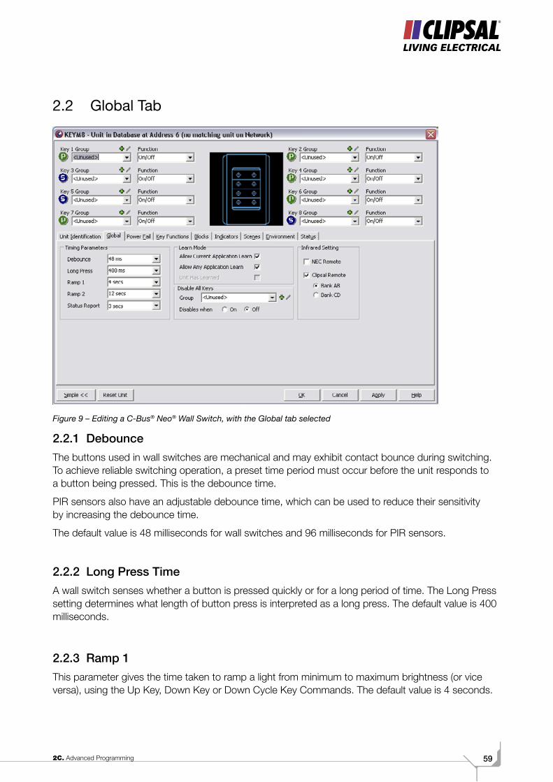
2.2 Global Tab
Figure 9 – Editing a C-Bus® Neo® Wall Switch, with the Global tab selected
2.2.1 Debounce The buttons used in wall switches are mechanical and may exhibit contact bounce during switching. To achieve reliable switching operation, a preset time period must occur before the unit responds to a button being pressed. This is the debounce time.
PIR sensors also have an adjustable debounce time, which can be used to reduce their sensitivity by increasing the debounce time.
The default value is 48 milliseconds for wall switches and 96 milliseconds for PIR sensors.
2.2.2 Long Press TimeA wall switch senses whether a button is pressed quickly or for a long period of time. The Long Press setting determines what length of button press is interpreted as a long press. The default value is 400 milliseconds.
2.2.3 Ramp 1This parameter gives the time taken to ramp a light from minimum to maximum brightness (or vice versa), using the Up Key, Down Key or Down Cycle Key Commands. The default value is 4 seconds.
C-BUS TRAINING MANUAL - VOL 260
2.2.4 Ramp 2This parameter gives the time taken to ramp a light from minimum to maximum brightness (or vice versa), using the Ramp Off or Ramp Recall Key Commands.
The default value is 12 seconds.
2.2.5 Status ReportWired C-Bus® uses a status reporting system (known as an MMI), which provides automatic detection and correction of discrepancies between the states of grouped inputs and outputs. This status reporting occurs at periodic intervals. Increasing the frequency of status reporting decreases the response time in which errors are corrected. However, it increases the amount of Network communication traffic. If different status report values exist in the same Network, the smallest value is used.
The default value is 3 seconds.
2.2.6 Learn Mode
Option Description
Allow Current Application Learn
Determines whether learn mode can be used to group channels with other units of the same Application Address.
Allow Any Application Learn
Determines whether learn mode can be used to group channels with other units of any Application Address. When grouping channels of units with different Application Addresses using learn mode, the Application Addresses of all units being included in the group will be changed to that of the unit from which learn mode is exited.
Unit Has Learned This indicates that the unit has been involved in a learn mode operation.
Table 4 – Learn mode options
2.2.7 Disable All KeysAllows the specification of a Group Address in the Enable Control application, which can be used to disable all keys on this Key Unit.
2.2.8 Infra-red SettingAllows the selection of Infra-red remote controls to use with this unit.

612C. Advanced Programming
2.3 Power Fail TabThe Power Fail tab shown in (Figure 10), allows you to set the level that each channel defaults to when recovering from a power failure. Note that Recovery tab settings in an output unit (such as a relay or dimmer) take precedence over Power Fail tab settings in an input unit. Generally, it is better to use the Recovery tab options in output units instead of the Power Fail tab options. If the 'Restore to previous levels' option is selected, each channel will be restored to the level it was at when the power failure occurred. If the 'Restore to preset levels' option is selected, the values selected on the sliders will be used as the restore level.
When the Synchronise slider option is checked, adjusting the level of any slider sets all to the same level.
Figure 10 – Editing a C-Bus® Neo® Wall Switch, with the Power Fail tab selected

C-BUS TRAINING MANUAL - VOL 262
2.4 Key Functions TabThe Key Functions tab (Figure 11) provides advanced setup for each wall switch button, allowing configurations that are not provided for in the simple set up screen.
Figure 11 – Editing a C-Bus® Neo® Wall Switch, with the Key Functions tab selected
Key functions can be assigned to the following types of button actions:
• Short Press (when the button is first pressed after the debounce time)
• Short Release (when the button is released before the long press time is reached)
• Long Press (when the button has been pressed and held for longer than the Long press time)
• Long Release (when the button is released after a long press has occurred).
The possible key functions are described in table 5.
632C. Advanced Programming
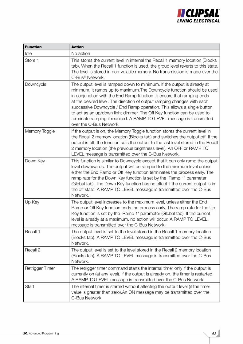
Function Action
Idle No action
Store 1 This stores the current level in internal the Recall 1 memory location (Blocks tab). When the Recall 1 function is used, the group level reverts to this state. The level is stored in non-volatile memory. No transmission is made over the C-Bus® Network.
Downcycle The output level is ramped down to minimum. If the output is already at minimum, it ramps up to maximum.The Downcycle function should be used in conjunction with the End Ramp function to ensure that ramping ends at the desired level. The direction of output ramping changes with each successive Downcycle / End Ramp operation. This allows a single button to act as an up/down light dimmer. The Off Key function can be used to terminate ramping if required. A RAMP TO LEVEL message is transmitted over the C-Bus Network.
Memory Toggle If the output is on, the Memory Toggle function stores the current level in the Recall 2 memory location (Blocks tab) and switches the output off. If the output is off, the function sets the output to the last level stored in the Recall 2 memory location (the previous brightness level). An OFF or RAMP TO LEVEL message is transmitted over the C-Bus Network.
Down Key This function is similar to Downcycle except that it can only ramp the output level downwards. The output will be ramped to the minimum level unless either the End Ramp or Off Key function terminates the process early. The ramp rate for the Down Key function is set by the 'Ramp 1' parameter (Global tab). The Down Key function has no effect if the current output is in the off state. A RAMP TO LEVEL message is transmitted over the C-Bus Network.
Up Key The output level increases to the maximum level, unless either the End Ramp or Off Key function ends the process early. The ramp rate for the Up Key function is set by the 'Ramp 1' parameter (Global tab). If the current level is already at a maximum, no action will occur. A RAMP TO LEVEL message is transmitted over the C-Bus Network.
Recall 1 The output level is set to the level stored in the Recall 1 memory location (Blocks tab). A RAMP TO LEVEL message is transmitted over the C-Bus Network.
Recall 2 The output level is set to the level stored in the Recall 2 memory location (Blocks tab). A RAMP TO LEVEL message is transmitted over the C-Bus Network.
Retrigger Timer The retrigger timer command starts the internal timer only if the output is currently on (at any level). If the output is already on, the timer is restarted. A RAMP TO LEVEL message is transmitted over the C-Bus Network.
Start The internal timer is started without affecting the output level (if the timer value is greater than zero).An ON message may be transmitted over the C-Bus Network.
C-BUS TRAINING MANUAL - VOL 264
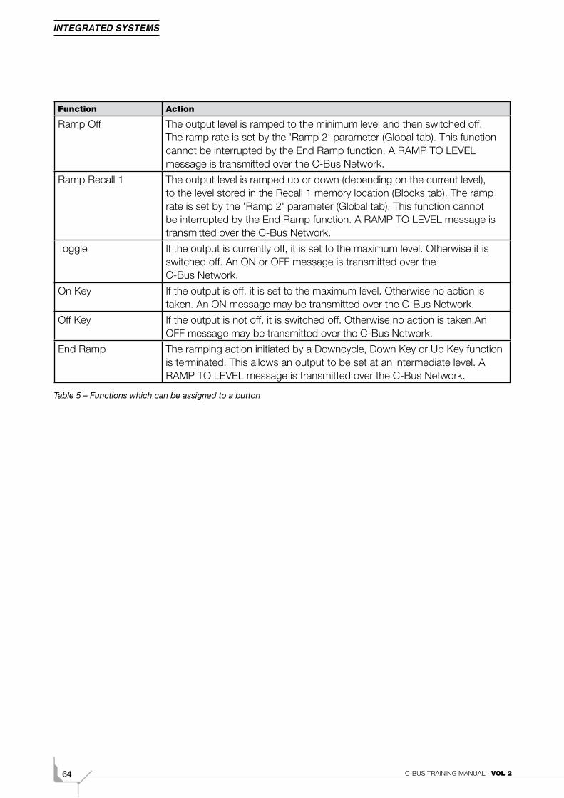
Function Action
Ramp Off The output level is ramped to the minimum level and then switched off. The ramp rate is set by the 'Ramp 2' parameter (Global tab). This function cannot be interrupted by the End Ramp function. A RAMP TO LEVEL message is transmitted over the C-Bus Network.
Ramp Recall 1 The output level is ramped up or down (depending on the current level), to the level stored in the Recall 1 memory location (Blocks tab). The ramp rate is set by the 'Ramp 2' parameter (Global tab). This function cannot be interrupted by the End Ramp function. A RAMP TO LEVEL message is transmitted over the C-Bus Network.
Toggle If the output is currently off, it is set to the maximum level. Otherwise it is switched off. An ON or OFF message is transmitted over the C-Bus Network.
On Key If the output is off, it is set to the maximum level. Otherwise no action is taken. An ON message may be transmitted over the C-Bus Network.
Off Key If the output is not off, it is switched off. Otherwise no action is taken.An OFF message may be transmitted over the C-Bus Network.
End Ramp The ramping action initiated by a Downcycle, Down Key or Up Key function is terminated. This allows an output to be set at an intermediate level. A RAMP TO LEVEL message is transmitted over the C-Bus Network.
Table 5 – Functions which can be assigned to a button
652C. Advanced Programming
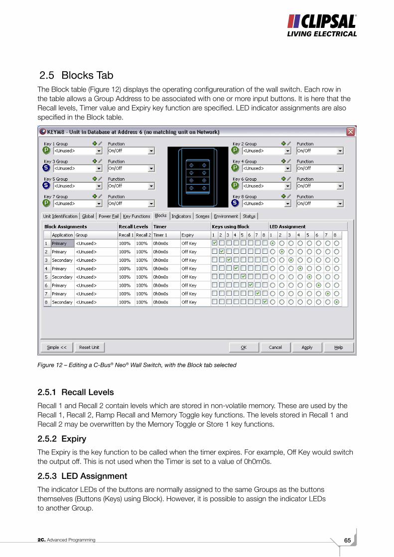
2.5 Blocks TabThe Block table (Figure 12) displays the operating configureuration of the wall switch. Each row in the table allows a Group Address to be associated with one or more input buttons. It is here that the Recall levels, Timer value and Expiry key function are specified. LED indicator assignments are also specified in the Block table.
Figure 12 – Editing a C-Bus® Neo® Wall Switch, with the Block tab selected
2.5.1 Recall LevelsRecall 1 and Recall 2 contain levels which are stored in non-volatile memory. These are used by the Recall 1, Recall 2, Ramp Recall and Memory Toggle key functions. The levels stored in Recall 1 and Recall 2 may be overwritten by the Memory Toggle or Store 1 key functions.
2.5.2 ExpiryThe Expiry is the key function to be called when the timer expires. For example, Off Key would switch the output off. This is not used when the Timer is set to a value of 0h0m0s.
2.5.3 LED AssignmentThe indicator LEDs of the buttons are normally assigned to the same Groups as the buttons themselves (Buttons (Keys) using Block). However, it is possible to assign the indicator LEDs to another Group.
C-BUS TRAINING MANUAL - VOL 266
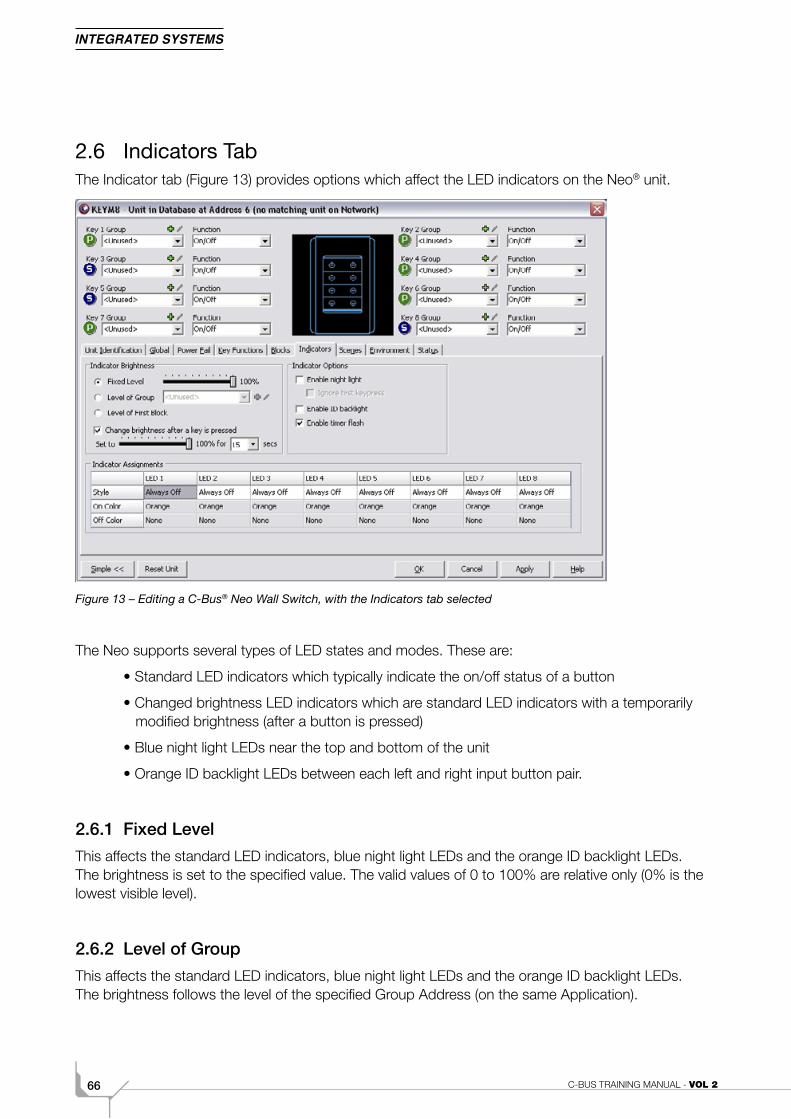
2.6 Indicators TabThe Indicator tab (Figure 13) provides options which affect the LED indicators on the Neo® unit.
Figure 13 – Editing a C-Bus® Neo Wall Switch, with the Indicators tab selected
The Neo supports several types of LED states and modes. These are:
• Standard LED indicators which typically indicate the on/off status of a button
• Changed brightness LED indicators which are standard LED indicators with a temporarily modified brightness (after a button is pressed)
• Blue night light LEDs near the top and bottom of the unit
• Orange ID backlight LEDs between each left and right input button pair.
2.6.1 Fixed LevelThis affects the standard LED indicators, blue night light LEDs and the orange ID backlight LEDs. The brightness is set to the specified value. The valid values of 0 to 100% are relative only (0% is the lowest visible level).
2.6.2 Level of GroupThis affects the standard LED indicators, blue night light LEDs and the orange ID backlight LEDs. The brightness follows the level of the specified Group Address (on the same Application).
672C. Advanced Programming
Change brightness after a button (key) is pressed
This option has several features. When enabled:
• The standard LED indicators do not function when the 'Enable night light' option is also enabled.
• Instead, the changed brightness LED indicators take effect whenever a button is pressed.
• The orange ID backlight LED levels temporarily change to the specified brightness whenever a button is pressed.
• The blue night light LEDs (if enabled) turn off temporarily whenever a button is pressed.
• If the 'Ignore first button press (keypress)' option is enabled, the button press which activates the changed brightness LED indicators will not change the state of the button pressed.
2.6.3 Enable Night LightThis activates the blue night light LEDs.
2.6.4 Ignore First Button Press (Keypress)This option only applies when the 'Change brightness after a button (key) is pressed' option is also enabled. The first button pressed in the period of time specified under that option will not change the state of the button pressed.
2.6.5 Enable ID BacklightThis activates the orange ID backlight LEDs.
2.6.6 Enable Timer FlashWhen enabled, a standard LED indicator will flash when a timer has been activated on its associated wall switch button.
C-BUS TRAINING MANUAL - VOL 268
2.7 Scenes Tab
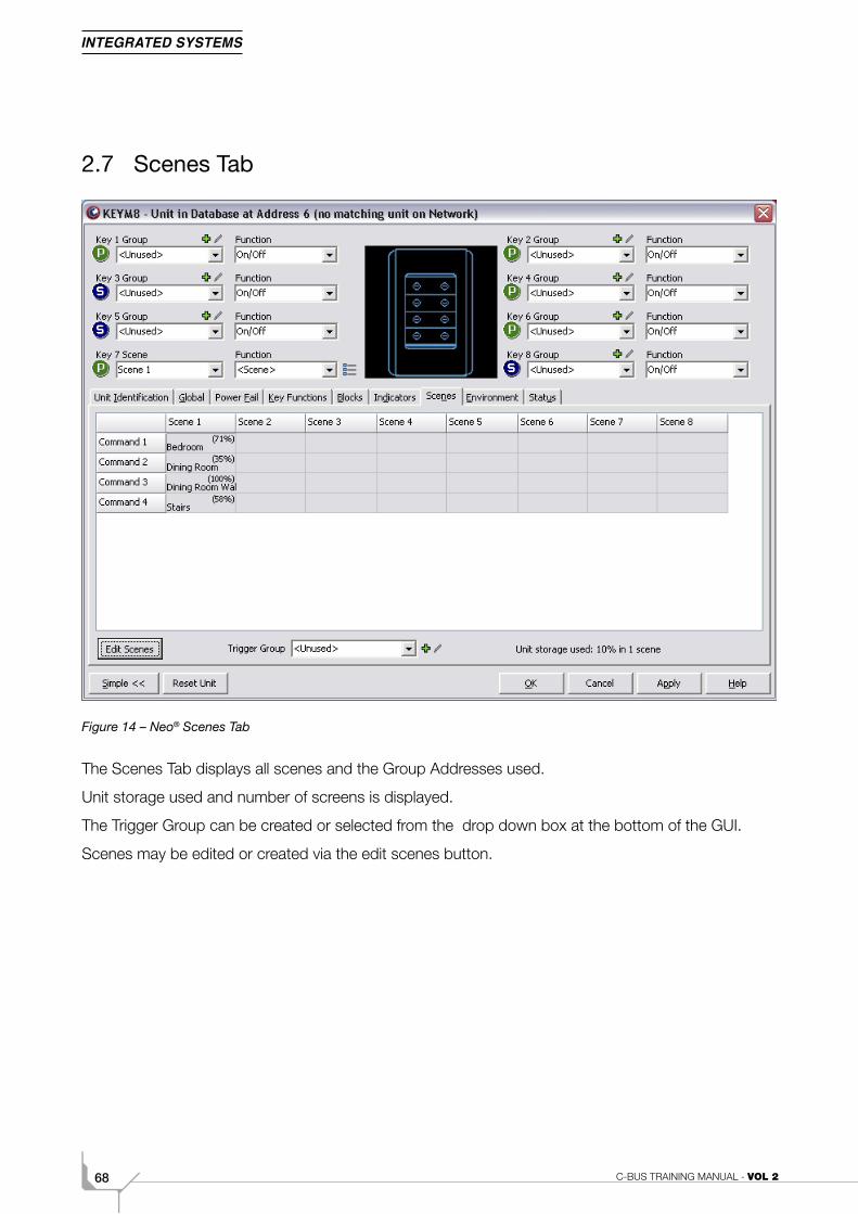
Figure 14 – Neo® Scenes Tab
The Scenes Tab displays all scenes and the Group Addresses used.
Unit storage used and number of screens is displayed.
The Trigger Group can be created or selected from the drop down box at the bottom of the GUI.
Scenes may be edited or created via the edit scenes button.
692C. Advanced Programming
2.8 Environment Tab
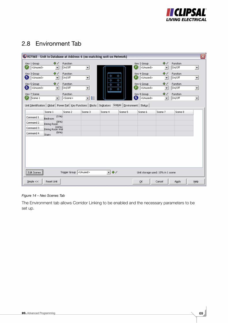
Figure 14 – Neo Scenes Tab
The Environment tab allows Corridor Linking to be enabled and the necessary parameters to be set up.
C-BUS TRAINING MANUAL - VOL 270
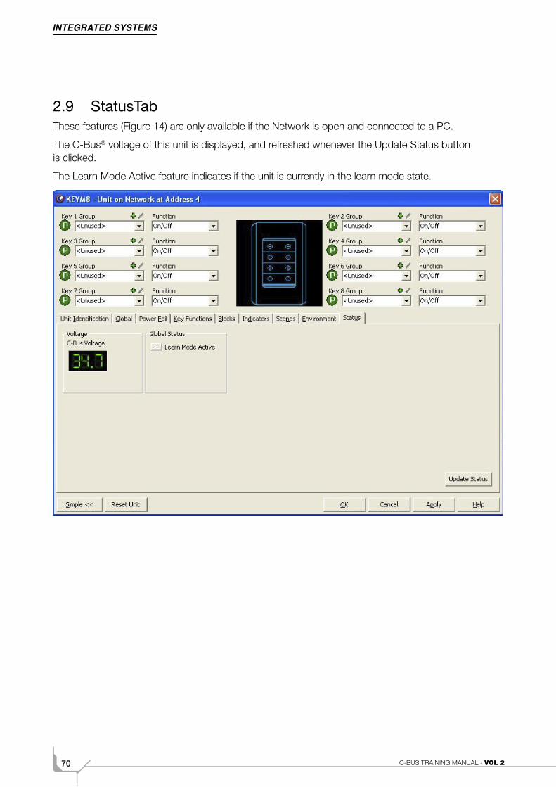
2.9 StatusTabThese features (Figure 14) are only available if the Network is open and connected to a PC.
The C-Bus® voltage of this unit is displayed, and refreshed whenever the Update Status button is clicked.
The Learn Mode Active feature indicates if the unit is currently in the learn mode state.
Figure 16 – Editing a C-Bus Neo Wall Switch, with the C-Bus Status tab selected
712C. Advanced Programming
3.0 Scene ControlThe implementation of scenes has many benefits. At the press of one button, a C-Bus® user has the control of many individual loads. These loads may be turned on, off or dimmed to a level.
There may be a requirement to have certain lights set to various levels for different functions. For example, say a dining room area has multiple low voltage lights. A scene could be used to set the light above the dining table to 100% and all others to 50%. This could be accomplished with a single button press. After dining, another scene could be used to configure the lounge room lighting in readiness for the guests.
3.1 Units with Scene CapabilityMany C-Bus units have the ability to store and execute scenes. These include:
• C-Bus Neo Wall Switches with Dynamic Labelling Technology (DLT)
• Ulti Saturn Series Wall Switches
• Reflection Series Wall Switches
• The Scene Master Scene Controller
• The C-Touch Colour Touch Screen
• The C-Touch Black & White Touch Screen
• The Multi Sensor.
This section focuses on the Neo® unit. However, the principles are similar for all scene capable units. The aim is for an individual button to control multiple loads (lights etc) to suit a particular requirement. Most products have manuals which contain useful information relating to scene programming for a specific unit type.
The majority of C-Bus units which are capable of scene control are C-Bus input units. C-Bus output units must be used in conjunction with scene capable units for a scene to be useful. Loads (such as lights) are controlled by C-Bus devices such as dimmers and relays, which must provide sufficient current carrying capability for the load.
C-BUS TRAINING MANUAL - VOL 272
3.2 Programming the Neo®
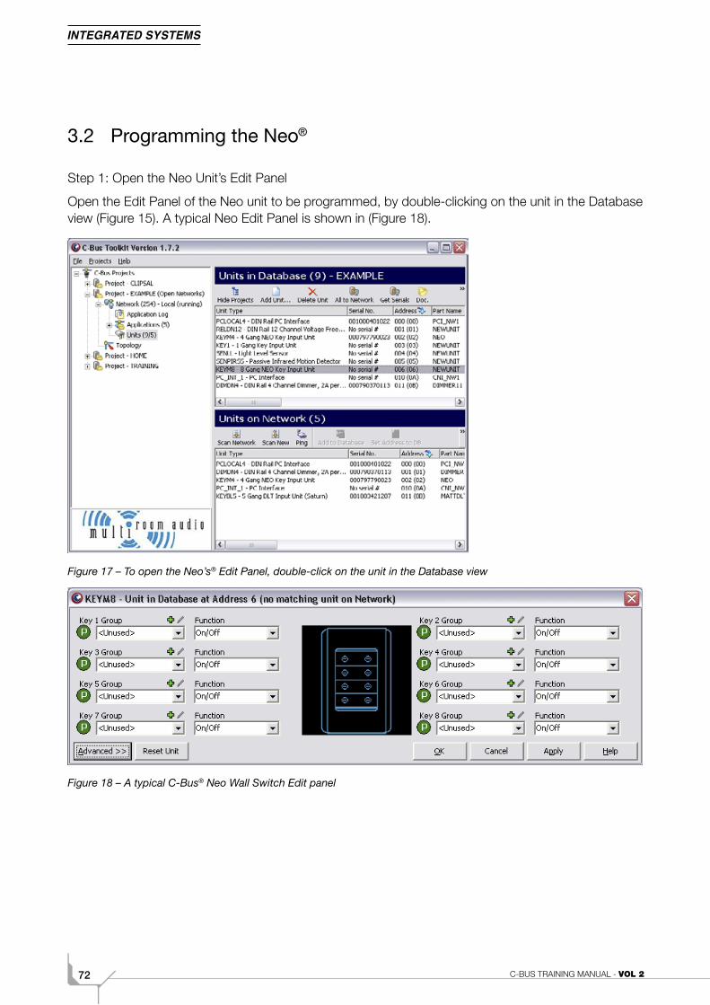
Step 1: Open the Neo Unit’s Edit Panel
Open the Edit Panel of the Neo unit to be programmed, by double-clicking on the unit in the Database view (Figure 15). A typical Neo Edit Panel is shown in (Figure 18).
Figure 17 – To open the Neo’s® Edit Panel, double-click on the unit in the Database view
Figure 18 – A typical C-Bus® Neo Wall Switch Edit panel
732C. Advanced Programming
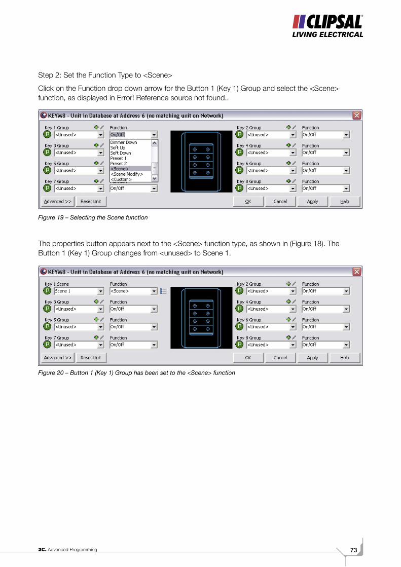
Step 2: Set the Function Type to <Scene>
Click on the Function drop down arrow for the Button 1 (Key 1) Group and select the <Scene> function, as displayed in Error! Reference source not found..
Figure 19 – Selecting the Scene function
The properties button appears next to the <Scene> function type, as shown in (Figure 18). The Button 1 (Key 1) Group changes from <unused> to Scene 1.
Figure 20 – Button 1 (Key 1) Group has been set to the <Scene> function
C-BUS TRAINING MANUAL - VOL 274
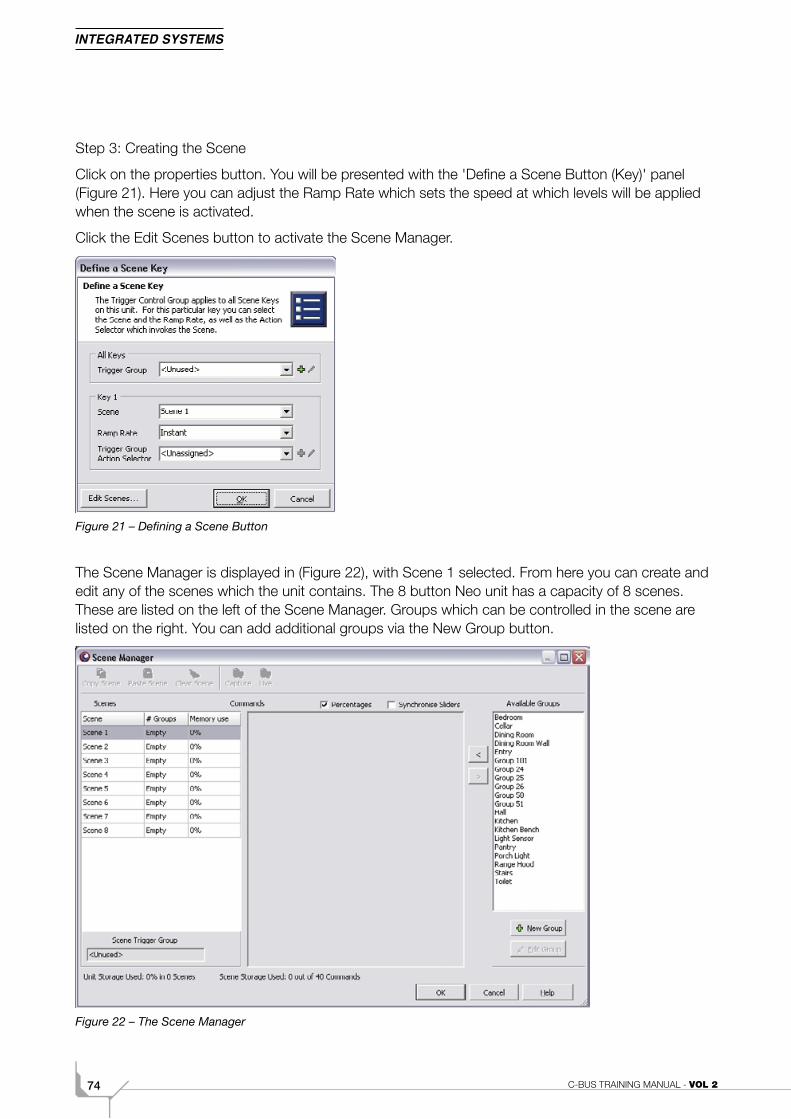
Step 3: Creating the Scene
Click on the properties button. You will be presented with the 'Define a Scene Button (Key)' panel (Figure 21). Here you can adjust the Ramp Rate which sets the speed at which levels will be applied when the scene is activated.
Click the Edit Scenes button to activate the Scene Manager.
Figure 21 – Defining a Scene Button
The Scene Manager is displayed in (Figure 22), with Scene 1 selected. From here you can create and edit any of the scenes which the unit contains. The 8 button Neo unit has a capacity of 8 scenes. These are listed on the left of the Scene Manager. Groups which can be controlled in the scene are listed on the right. You can add additional groups via the New Group button.
Figure 22 – The Scene Manager
752C. Advanced Programming
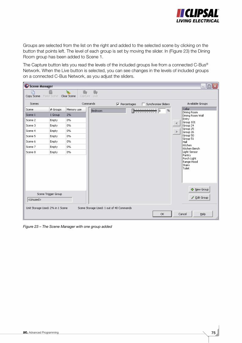
Groups are selected from the list on the right and added to the selected scene by clicking on the button that points left. The level of each group is set by moving the slider. In (Figure 23) the Dining Room group has been added to Scene 1.
The Capture button lets you read the levels of the included groups live from a connected C-Bus® Network. When the Live button is selected, you can see changes in the levels of included groups on a connected C-Bus Network, as you adjust the sliders.
Figure 23 – The Scene Manager with one group added
C-BUS TRAINING MANUAL - VOL 276
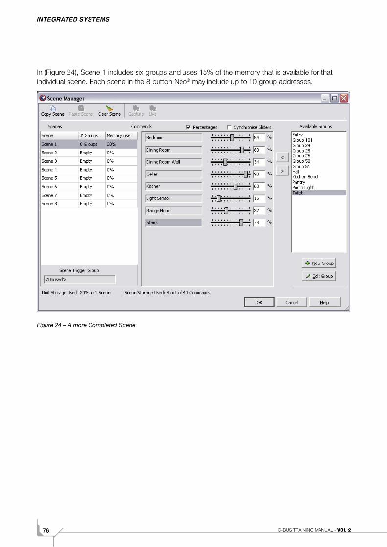
In (Figure 24), Scene 1 includes six groups and uses 15% of the memory that is available for that individual scene. Each scene in the 8 button Neo® may include up to 10 group addresses.
Figure 24 – A more Completed Scene
772C. Advanced Programming
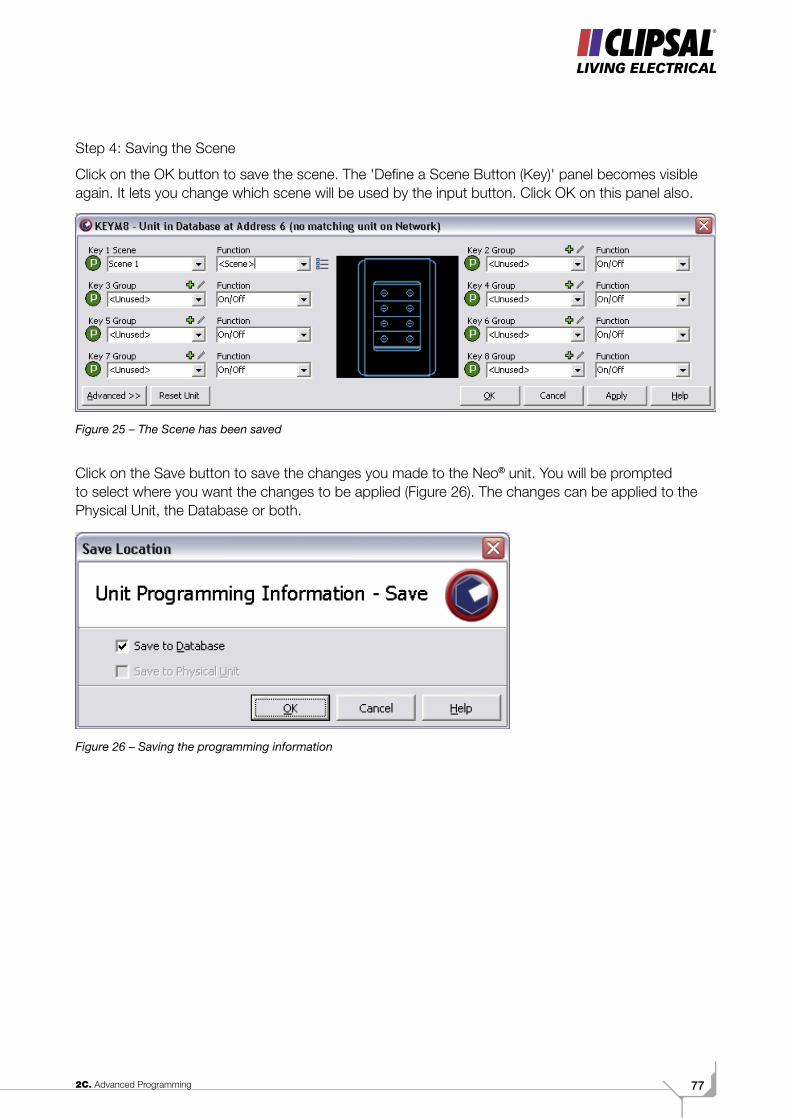
Step 4: Saving the Scene
Click on the OK button to save the scene. The 'Define a Scene Button (Key)' panel becomes visible again. It lets you change which scene will be used by the input button. Click OK on this panel also.
Figure 25 – The Scene has been saved
Click on the Save button to save the changes you made to the Neo® unit. You will be prompted to select where you want the changes to be applied (Figure 26). The changes can be applied to the Physical Unit, the Database or both.
Figure 26 – Saving the programming information
C-BUS TRAINING MANUAL - VOL 278
Volume 2DDynamic Labelling
792D. DLT
Scope
This manual aims to provide an installer with the basic skills needed to program and use the C-Bus® Dynamic Labelling Technology (DLT) Unit. A fundamental technical background is required.
To get the most out of this manual, be sure to:
• Read all chapters
• Perform all exercises.
Learning Outcomes
By the end of this module, you should be competent in:
• Programming the DLT
• Labelling the DLT
• Setting the clock.
C-BUS TRAINING MANUAL - VOL 280
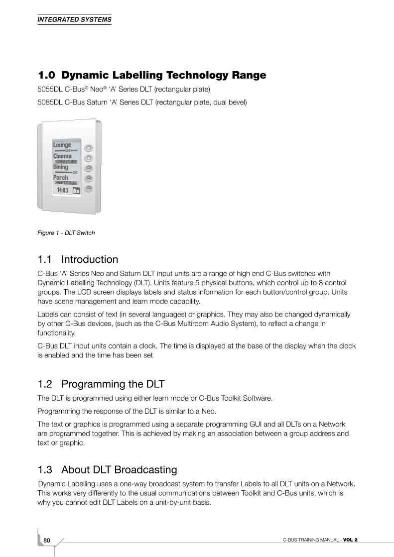
1.0 Dynamic Labelling Technology Range5055DL C-Bus® Neo® ‘A’ Series DLT (rectangular plate)
5085DL C-Bus Saturn ‘A’ Series DLT (rectangular plate, dual bevel)
Figure 1 - DLT Switch
1.1 IntroductionC-Bus ‘A’ Series Neo and Saturn DLT input units are a range of high end C-Bus switches with Dynamic Labelling Technology (DLT). Units feature 5 physical buttons, which control up to 8 control groups. The LCD screen displays labels and status information for each button/control group. Units have scene management and learn mode capability.
Labels can consist of text (in several languages) or graphics. They may also be changed dynamically by other C-Bus devices, (such as the C-Bus Multiroom Audio System), to reflect a change in functionality.
C-Bus DLT input units contain a clock. The time is displayed at the base of the display when the clock is enabled and the time has been set
1.2 Programming the DLTThe DLT is programmed using either learn mode or C-Bus Toolkit Software.
Programming the response of the DLT is similar to a Neo.
The text or graphics is programmed using a separate programming GUI and all DLTs on a Network are programmed together. This is achieved by making an association between a group address and text or graphic.
1.3 About DLT BroadcastingDynamic Labelling uses a one-way broadcast system to transfer Labels to all DLT units on a Network. This works very differently to the usual communications between Toolkit and C-Bus units, which is why you cannot edit DLT Labels on a unit-by-unit basis.
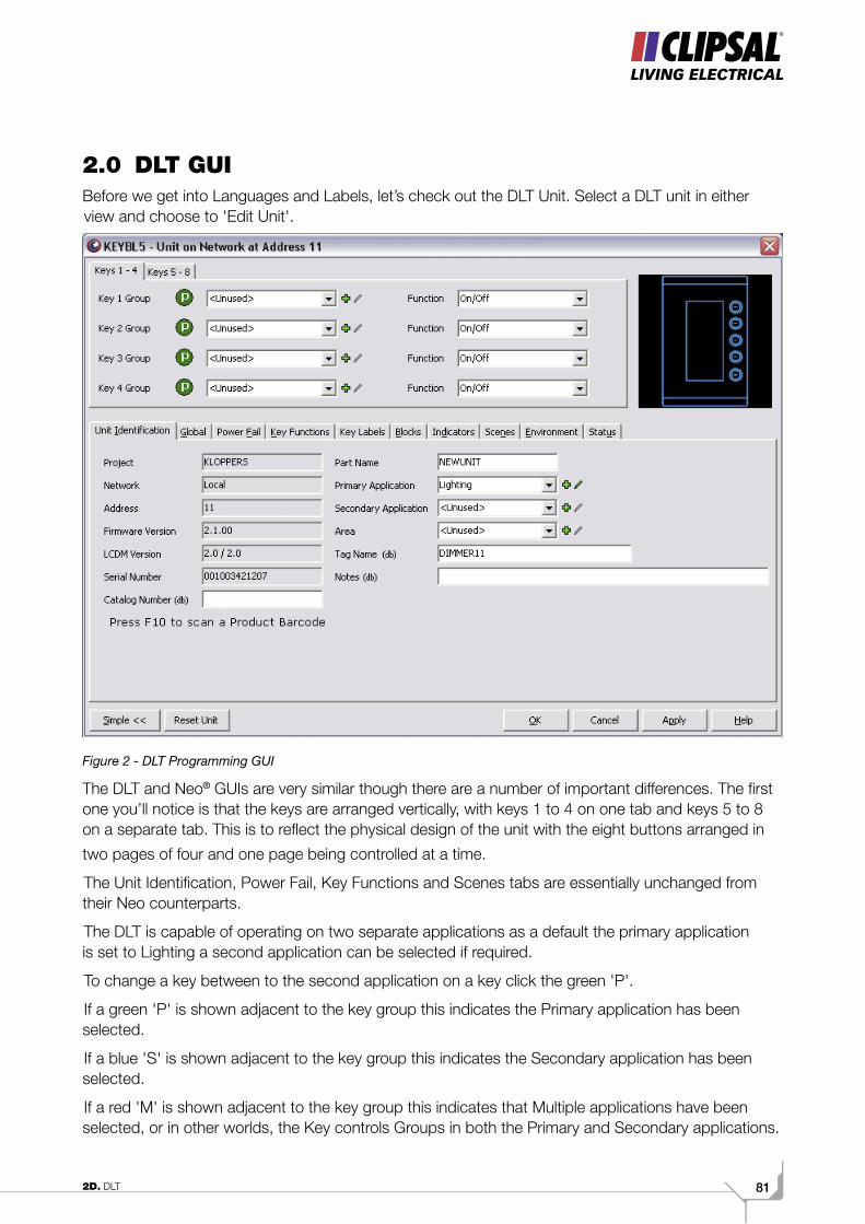
812D. DLT
2.0 DLT GUIBefore we get into Languages and Labels, let’s check out the DLT Unit. Select a DLT unit in either view and choose to 'Edit Unit'.
Figure 2 - DLT Programming GUI
The DLT and Neo® GUIs are very similar though there are a number of important differences. The first one you’ll notice is that the keys are arranged vertically, with keys 1 to 4 on one tab and keys 5 to 8 on a separate tab. This is to reflect the physical design of the unit with the eight buttons arranged in
two pages of four and one page being controlled at a time.
The Unit Identification, Power Fail, Key Functions and Scenes tabs are essentially unchanged from their Neo counterparts.
The DLT is capable of operating on two separate applications as a default the primary application is set to Lighting a second application can be selected if required.
To change a key between to the second application on a key click the green 'P'.
If a green 'P' is shown adjacent to the key group this indicates the Primary application has been selected.
If a blue 'S' is shown adjacent to the key group this indicates the Secondary application has been selected.
If a red 'M' is shown adjacent to the key group this indicates that Multiple applications have been selected, or in other worlds, the Key controls Groups in both the Primary and Secondary applications.
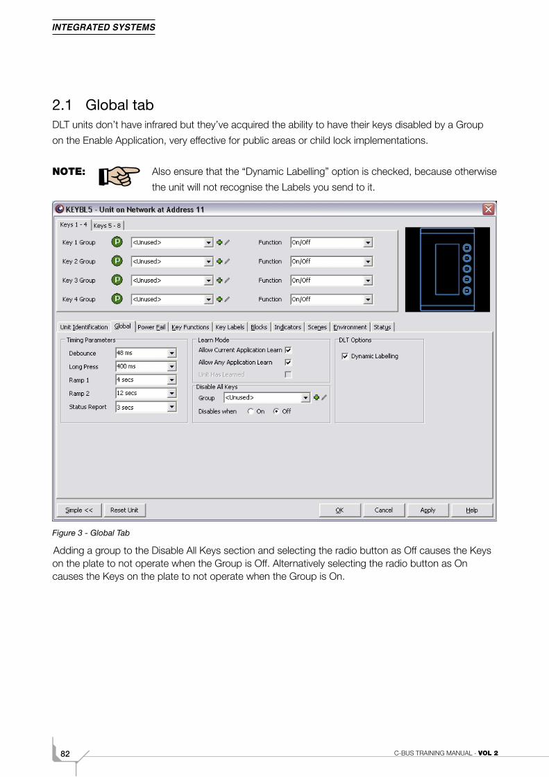
C-BUS TRAINING MANUAL - VOL 282
2.1 Global tabDLT units don’t have infrared but they’ve acquired the ability to have their keys disabled by a Group
on the Enable Application, very effective for public areas or child lock implementations.
NOTE: Also ensure that the “Dynamic Labelling” option is checked, because otherwise
the unit will not recognise the Labels you send to it.
Figure 3 - Global Tab
Adding a group to the Disable All Keys section and selecting the radio button as Off causes the Keys on the plate to not operate when the Group is Off. Alternatively selecting the radio button as On causes the Keys on the plate to not operate when the Group is On.

832D. DLT
2.2 Blocks tabThe Blocks tab provides an overview of which groups are assigned to which keys.
Figure 4 - DLT Blocks Tab
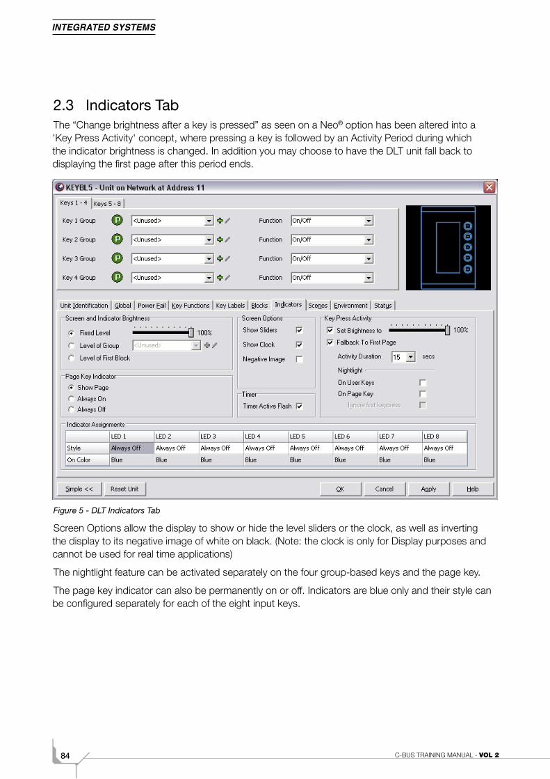
C-BUS TRAINING MANUAL - VOL 284
2.3 Indicators TabThe “Change brightness after a key is pressed” as seen on a Neo® option has been altered into a 'Key Press Activity' concept, where pressing a key is followed by an Activity Period during which the indicator brightness is changed. In addition you may choose to have the DLT unit fall back to displaying the first page after this period ends.
Figure 5 - DLT Indicators Tab
Screen Options allow the display to show or hide the level sliders or the clock, as well as inverting the display to its negative image of white on black. (Note: the clock is only for Display purposes and cannot be used for real time applications)
The nightlight feature can be activated separately on the four group-based keys and the page key.
The page key indicator can also be permanently on or off. Indicators are blue only and their style can be configured separately for each of the eight input keys.
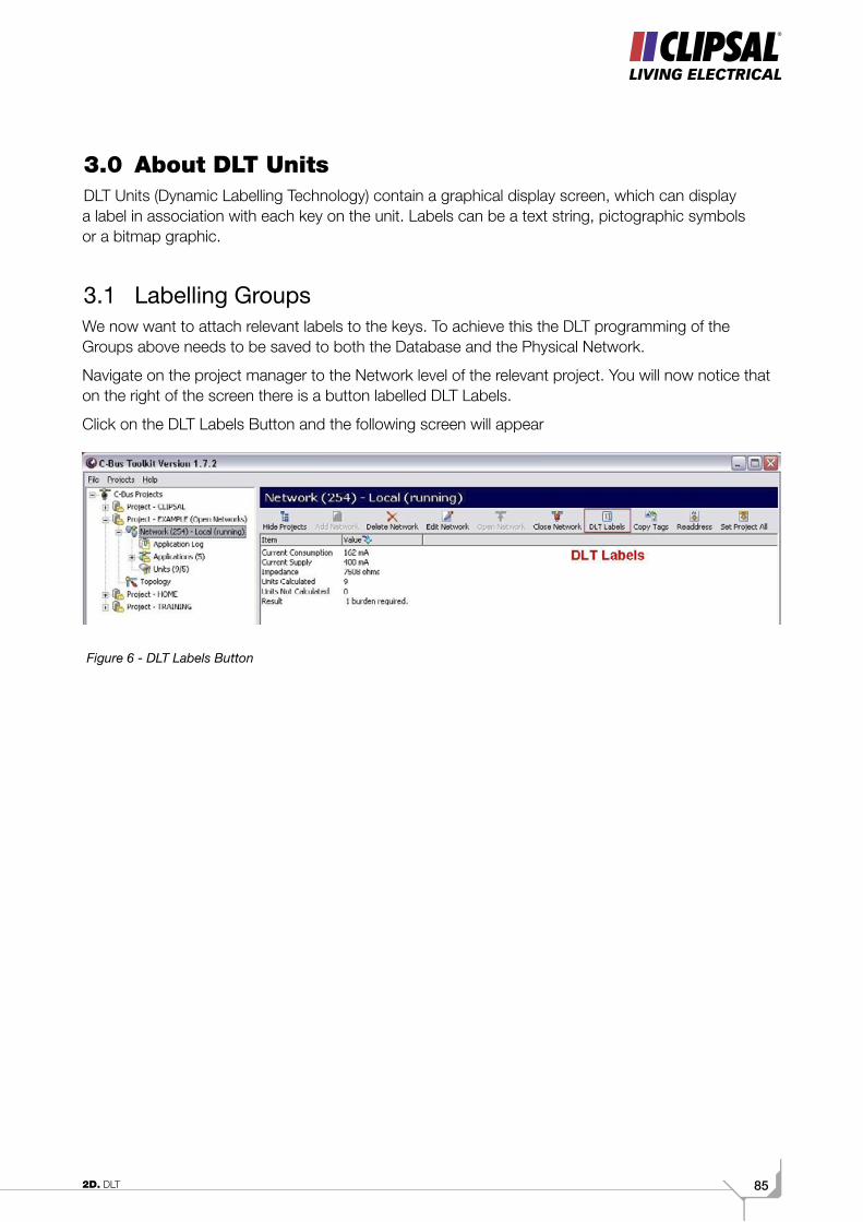
852D. DLT
3.0 About DLT UnitsDLT Units (Dynamic Labelling Technology) contain a graphical display screen, which can display a label in association with each key on the unit. Labels can be a text string, pictographic symbols or a bitmap graphic.
3.1 Labelling GroupsWe now want to attach relevant labels to the keys. To achieve this the DLT programming of the Groups above needs to be saved to both the Database and the Physical Network.
Navigate on the project manager to the Network level of the relevant project. You will now notice that on the right of the screen there is a button labelled DLT Labels.
Click on the DLT Labels Button and the following screen will appear
Figure 6 - DLT Labels Button
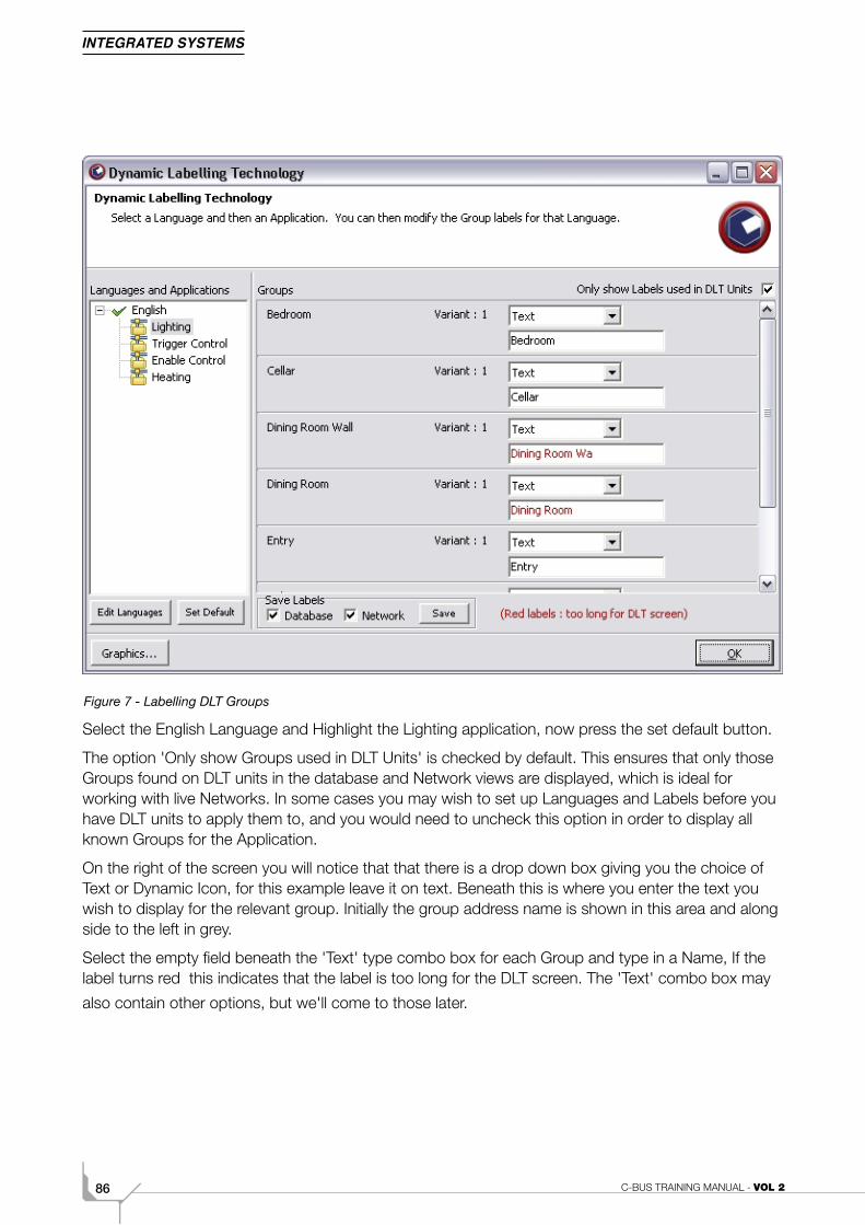
C-BUS TRAINING MANUAL - VOL 286
Figure 7 - Labelling DLT Groups
Select the English Language and Highlight the Lighting application, now press the set default button.
The option 'Only show Groups used in DLT Units' is checked by default. This ensures that only those Groups found on DLT units in the database and Network views are displayed, which is ideal for working with live Networks. In some cases you may wish to set up Languages and Labels before you have DLT units to apply them to, and you would need to uncheck this option in order to display all known Groups for the Application.
On the right of the screen you will notice that that there is a drop down box giving you the choice of Text or Dynamic Icon, for this example leave it on text. Beneath this is where you enter the text you wish to display for the relevant group. Initially the group address name is shown in this area and along side to the left in grey.
Select the empty field beneath the 'Text' type combo box for each Group and type in a Name, If the label turns red this indicates that the label is too long for the DLT screen. The 'Text' combo box may
also contain other options, but we'll come to those later.
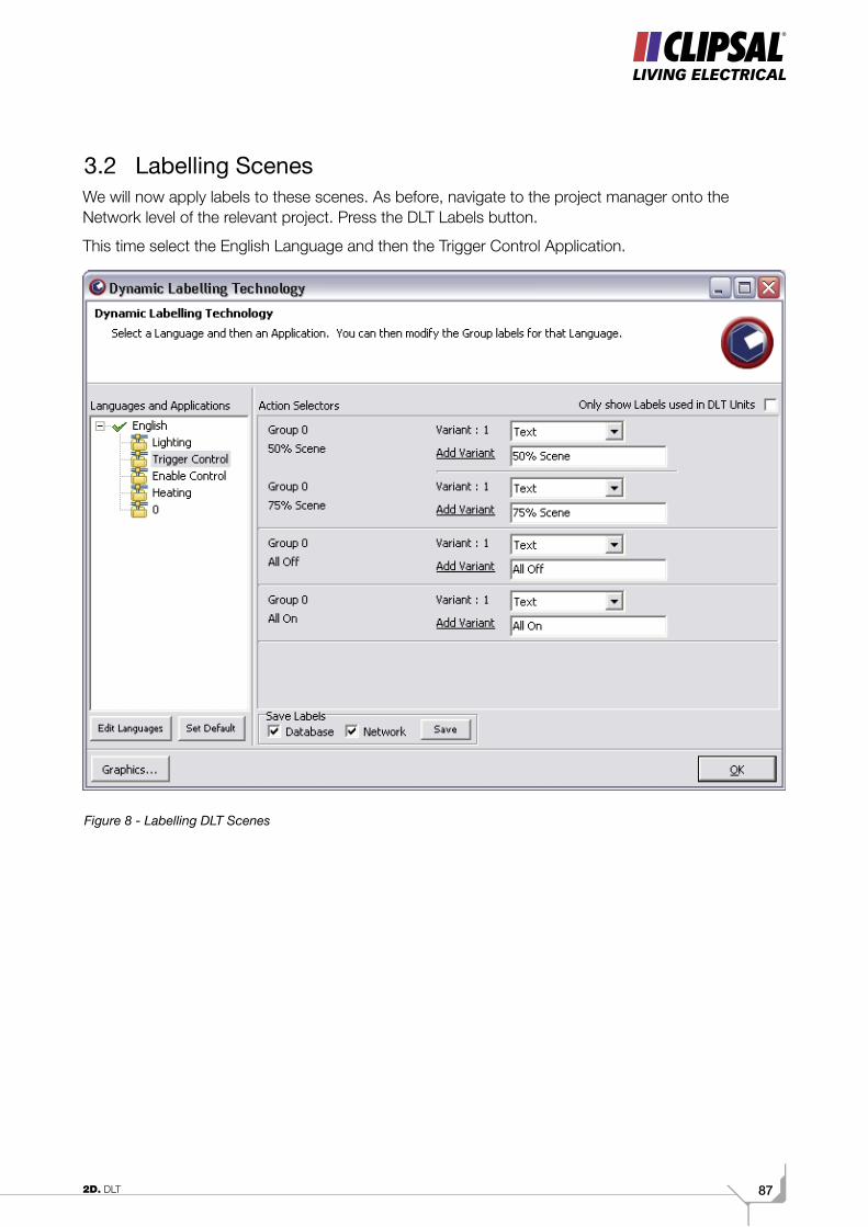
872D. DLT
3.2 Labelling ScenesWe will now apply labels to these scenes. As before, navigate to the project manager onto the Network level of the relevant project. Press the DLT Labels button.
This time select the English Language and then the Trigger Control Application.
Figure 8 - Labelling DLT Scenes
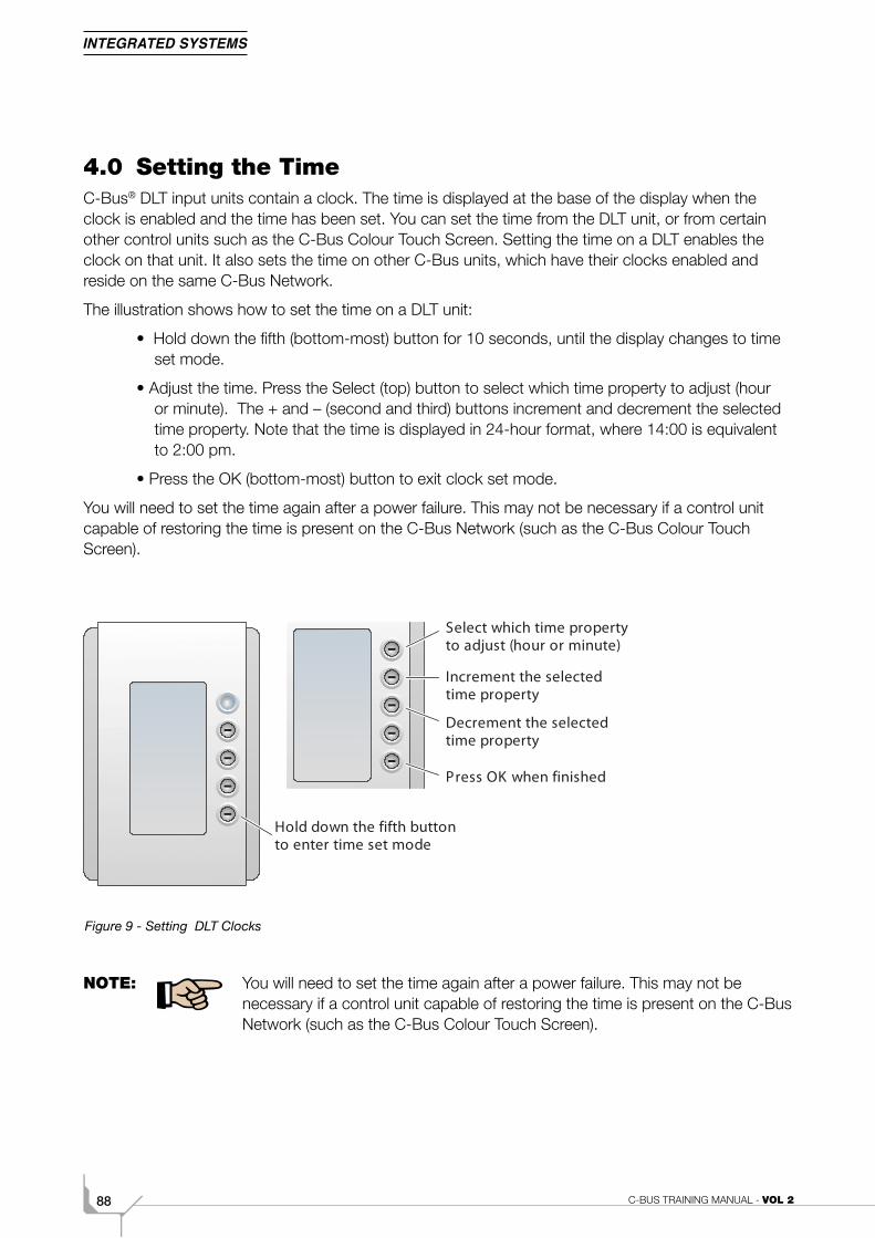
C-BUS TRAINING MANUAL - VOL 288
4.0 Setting the TimeC-Bus® DLT input units contain a clock. The time is displayed at the base of the display when the clock is enabled and the time has been set. You can set the time from the DLT unit, or from certain other control units such as the C-Bus Colour Touch Screen. Setting the time on a DLT enables the clock on that unit. It also sets the time on other C-Bus units, which have their clocks enabled and reside on the same C-Bus Network.
The illustration shows how to set the time on a DLT unit:
• Hold down the fifth (bottom-most) button for 10 seconds, until the display changes to time set mode.
• Adjust the time. Press the Select (top) button to select which time property to adjust (hour or minute). The + and – (second and third) buttons increment and decrement the selected time property. Note that the time is displayed in 24-hour format, where 14:00 is equivalent to 2:00 pm.
• Press the OK (bottom-most) button to exit clock set mode.
You will need to set the time again after a power failure. This may not be necessary if a control unit capable of restoring the time is present on the C-Bus Network (such as the C-Bus Colour Touch Screen).
Figure 9 - Setting DLT Clocks
NOTE: You will need to set the time again after a power failure. This may not be necessary if a control unit capable of restoring the time is present on the C-Bus Network (such as the C-Bus Colour Touch Screen).
Hold down the fifth buttonto enter time set mode
Select which time propertyto adjust (hour or minute)
Increment the selectedtime property
Decrement the selectedtime property
Press OK when finished

892D. DLT
C-BUS TRAINING MANUAL - VOL 290
Volume 2ENetwork Bridges
912E. Network Bridges
Scope
This manual aims to provide an installer with the basic skills needed to program and use
The C-Bus® Network Bridges. A fundamental technical background is required.
To get the most out of this manual, be sure to:
• Read all chapters.
Learning Outcomes
By the end of this module, you should competent in:
• Setting up multiple Networks
• Configureuring Network Bridges.
C-BUS TRAINING MANUAL - VOL 292
1.0 Network Bridges Introduction
The C-Bus® DIN Rail mounted Network Bridge, is a Network support device that provides a communication channel between C-Bus units on separate Networks. This makes programming and monitoring of C-Bus devices on remote Networks possible from a single point.
The Network Bridge consists of two identical halves, each needing to be individually programmed with their own operating parameters.
The Network Bridge serves the following functions:
• Provides electrical isolation between adjacent Networks
• Allows messages to pass between Networks
• Provides a path for remote programming of units across Networks
• Provides a Network burden
• Provides a system clock for data transmission synchronisation.
The Network Bridge should be used under the following conditions:
• When the total current required to run the Network exceeds 2A
• When the number of C-Bus units exceeds 100 units
• When the total cable length in the installation exceeds 1000 metres
• When there is a requirement to provide separation between Networks, such as in the case of a multi storey building where a Network Bridge is used between floors to provide segregation.
A Network Bridge providing electrical isolation does not permit power transmission through the device. Therefore separate power supplies are required on both sides of the bridge.
932E. Network Bridges
1.1 Capabilities
The C-Bus® Network Bridge allows:
• Relaying of messages between Networks, to allow all Units on multiple Networks within the one installation to be programmed and monitored from a central location
• Transmission of On, Off and Ramp to Level Commands, to allow the control of Output Units on one Network by Input Units on another. Units across several Networks can be assigned the same Group Address to provide this high level of control.
1.2 Limitations
The C-Bus Network Bridge has several limitations including:
• The MMI Status Report cannot be transferred across a Bridge and therefore an Input Unit controlling a distant Output Unit over a Bridge cannot automatically correct itself
• As a Bridge can only send messages to one other Network as well as the adjacent Network, you are limited in inter-Network control when Bridges are used in cascade form
• The maximum number of Network Bridges that can be cascaded is six (in-series). An alternative Network Topology will be required to interconnect more than seven Networks.
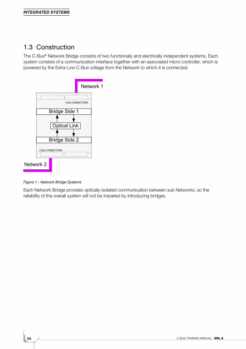
C-BUS TRAINING MANUAL - VOL 294
1.3 ConstructionThe C-Bus® Network Bridge consists of two functionally and electrically independent systems. Each system consists of a communication interface together with an associated micro-controller, which is powered by the Extra Low C-Bus voltage from the Network to which it is connected.
Figure 1 - Network Bridge Systems
Each Network Bridge provides optically isolated communication between sub Networks, so the reliability of the overall system will not be impaired by introducing bridges.
C-Bus CONNECTIONS
C-Bus CONNECTIONS
Bridge Side 1
Optical Link
Bridge Side 2
Network 2
Network 1
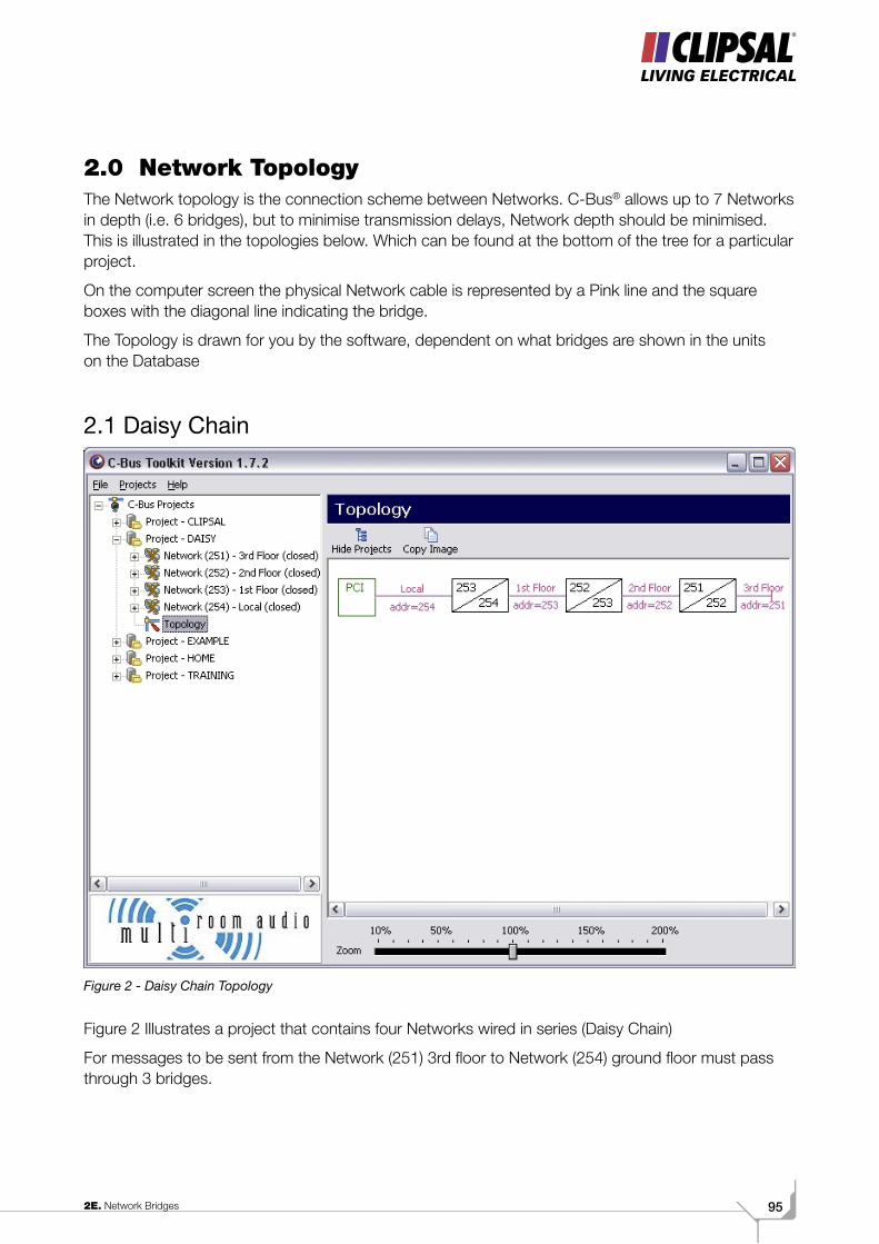
952E. Network Bridges
2.0 Network Topology The Network topology is the connection scheme between Networks. C-Bus® allows up to 7 Networks in depth (i.e. 6 bridges), but to minimise transmission delays, Network depth should be minimised. This is illustrated in the topologies below. Which can be found at the bottom of the tree for a particular project.
On the computer screen the physical Network cable is represented by a Pink line and the square boxes with the diagonal line indicating the bridge.
The Topology is drawn for you by the software, dependent on what bridges are shown in the units on the Database
2.1 Daisy Chain
Figure 2 - Daisy Chain Topology
Figure 2 Illustrates a project that contains four Networks wired in series (Daisy Chain)
For messages to be sent from the Network (251) 3rd floor to Network (254) ground floor must pass through 3 bridges.
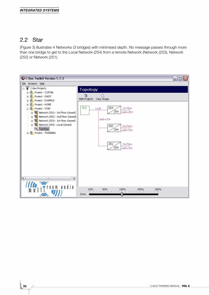
C-BUS TRAINING MANUAL - VOL 296
2.2 Star(Figure 3) illustrates 4 Networks (3 bridges) with minimised depth. No message passes through more than one bridge to get to the Local Network (254) from a remote Network (Network (253), Network (252) or Network (251).
Figure 3 - Star Topology
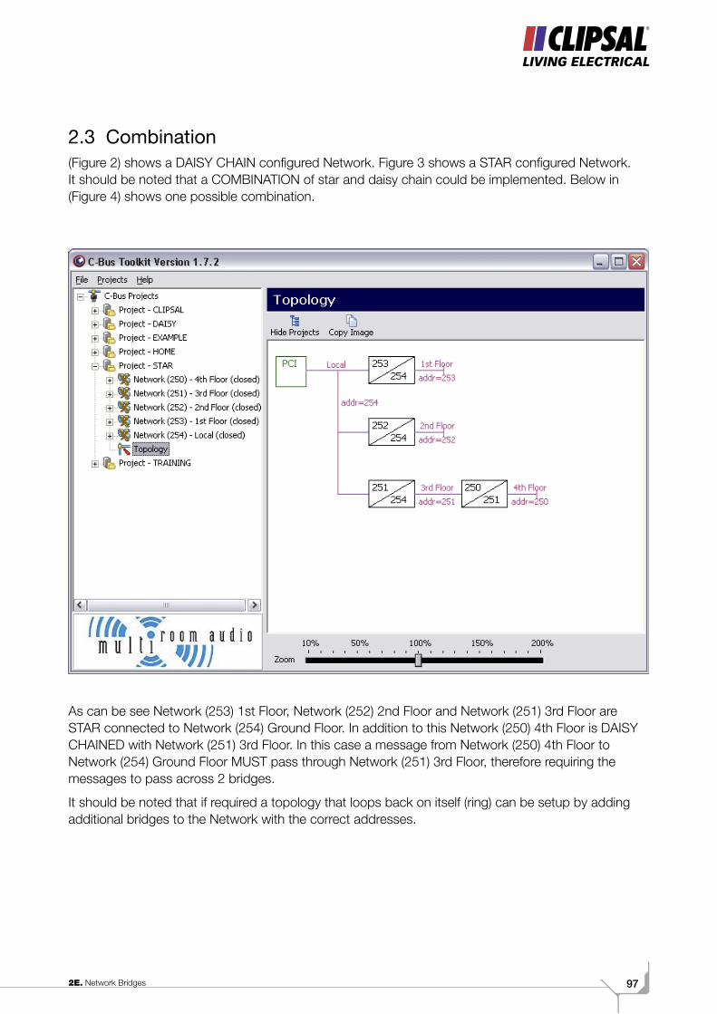
972E. Network Bridges
2.3 Combination(Figure 2) shows a DAISY CHAIN configured Network. Figure 3 shows a STAR configured Network. It should be noted that a COMBINATION of star and daisy chain could be implemented. Below in (Figure 4) shows one possible combination.
Figure 4 - Combination of Star and chain Topology
As can be see Network (253) 1st Floor, Network (252) 2nd Floor and Network (251) 3rd Floor are STAR connected to Network (254) Ground Floor. In addition to this Network (250) 4th Floor is DAISY CHAINED with Network (251) 3rd Floor. In this case a message from Network (250) 4th Floor to Network (254) Ground Floor MUST pass through Network (251) 3rd Floor, therefore requiring the messages to pass across 2 bridges.
It should be noted that if required a topology that loops back on itself (ring) can be setup by adding additional bridges to the Network with the correct addresses.
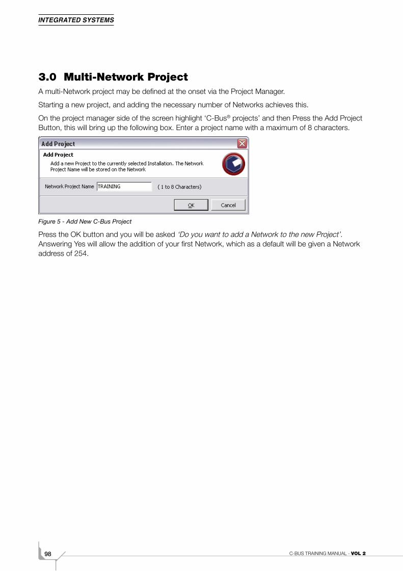
C-BUS TRAINING MANUAL - VOL 298
3.0 Multi-Network ProjectA multi-Network project may be defined at the onset via the Project Manager.
Starting a new project, and adding the necessary number of Networks achieves this.
On the project manager side of the screen highlight ‘C-Bus® projects’ and then Press the Add Project Button, this will bring up the following box. Enter a project name with a maximum of 8 characters.
Figure 5 - Add New C-Bus Project
Press the OK button and you will be asked ‘Do you want to add a Network to the new Project’. Answering Yes will allow the addition of your first Network, which as a default will be given a Network address of 254.
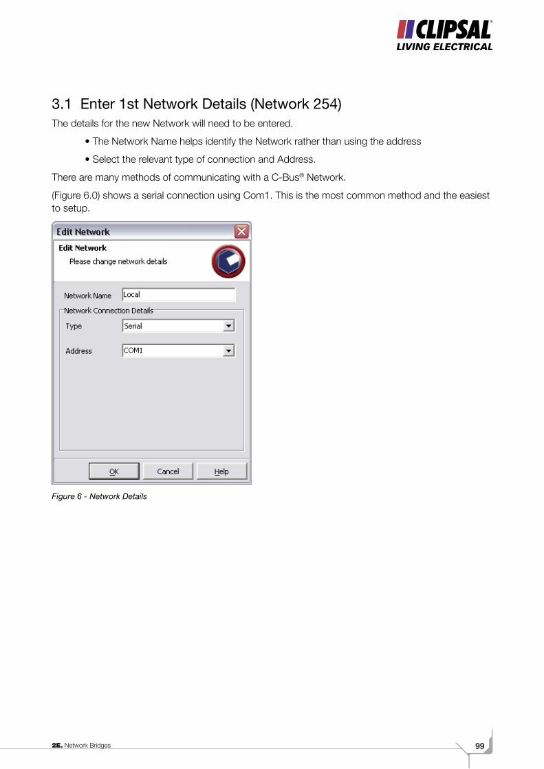
992E. Network Bridges
3.1 Enter 1st Network Details (Network 254)The details for the new Network will need to be entered.
• The Network Name helps identify the Network rather than using the address
• Select the relevant type of connection and Address.
There are many methods of communicating with a C-Bus® Network.
(Figure 6.0) shows a serial connection using Com1. This is the most common method and the easiest to setup.
Figure 6 - Network Details
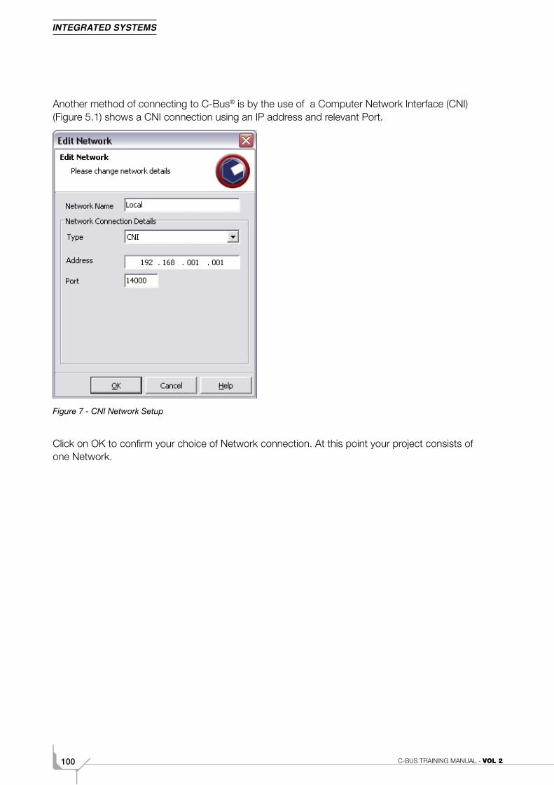
C-BUS TRAINING MANUAL - VOL 2100
Another method of connecting to C-Bus® is by the use of a Computer Network Interface (CNI) (Figure 5.1) shows a CNI connection using an IP address and relevant Port.
Figure 7 - CNI Network Setup
Click on OK to confirm your choice of Network connection. At this point your project consists of one Network.
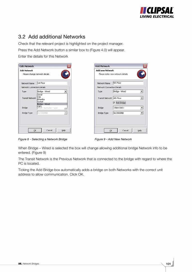
1012E. Network Bridges
3.2 Add additional Networks Check that the relevant project is highlighted on the project manager.
Press the Add Network button a similar box to (Figure 4.0) will appear.
Enter the details for this Network
Figure 8 - Selecting a Network Bridge Figure 9 - Add New Network When Bridge – Wired is selected the box will change allowing additional bridge Network info to be entered. (Figure 9)
The Transit Network is the Previous Network that is connected to the bridge with regard to where the PC is located.
Ticking the Add Bridge box automatically adds a bridge on both Networks with the correct unit address to allow communication. Click OK.
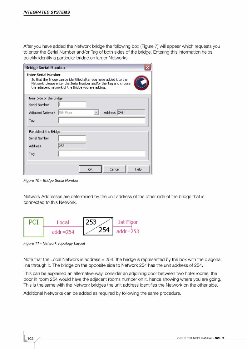
C-BUS TRAINING MANUAL - VOL 2102
After you have added the Network bridge the following box (Figure 7) will appear which requests you to enter the Serial Number and/or Tag of both sides of the bridge. Entering this information helps quickly identify a particular bridge on larger Networks.
Figure 10 - Bridge Serial Number
Network Addresses are determined by the unit address of the other side of the bridge that is connected to this Network.
Figure 11 - Network Topology Layout
Note that the Local Network is address = 254, the bridge is represented by the box with the diagonal line through it. The bridge on the opposite side to Network 254 has the unit address of 254.
This can be explained an alternative way, consider an adjoining door between two hotel rooms, the door in room 254 would have the adjacent rooms number on it, hence showing where you are going. This is the same with the Network bridges the unit address identifies the Network on the other side.
Additional Networks can be added as required by following the same procedure.
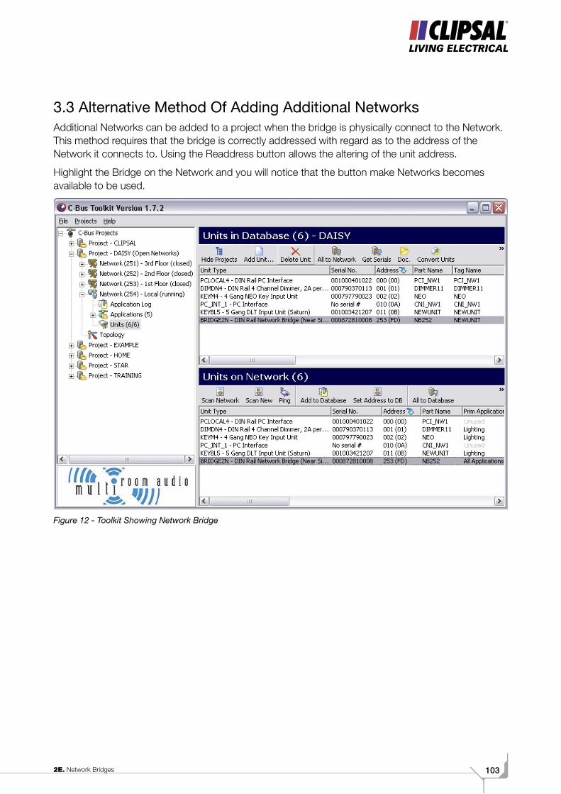
1032E. Network Bridges
3.3 Alternative Method Of Adding Additional NetworksAdditional Networks can be added to a project when the bridge is physically connect to the Network. This method requires that the bridge is correctly addressed with regard as to the address of the Network it connects to. Using the Readdress button allows the altering of the unit address.
Highlight the Bridge on the Network and you will notice that the button make Networks becomes available to be used.
Figure 12 - Toolkit Showing Network Bridge
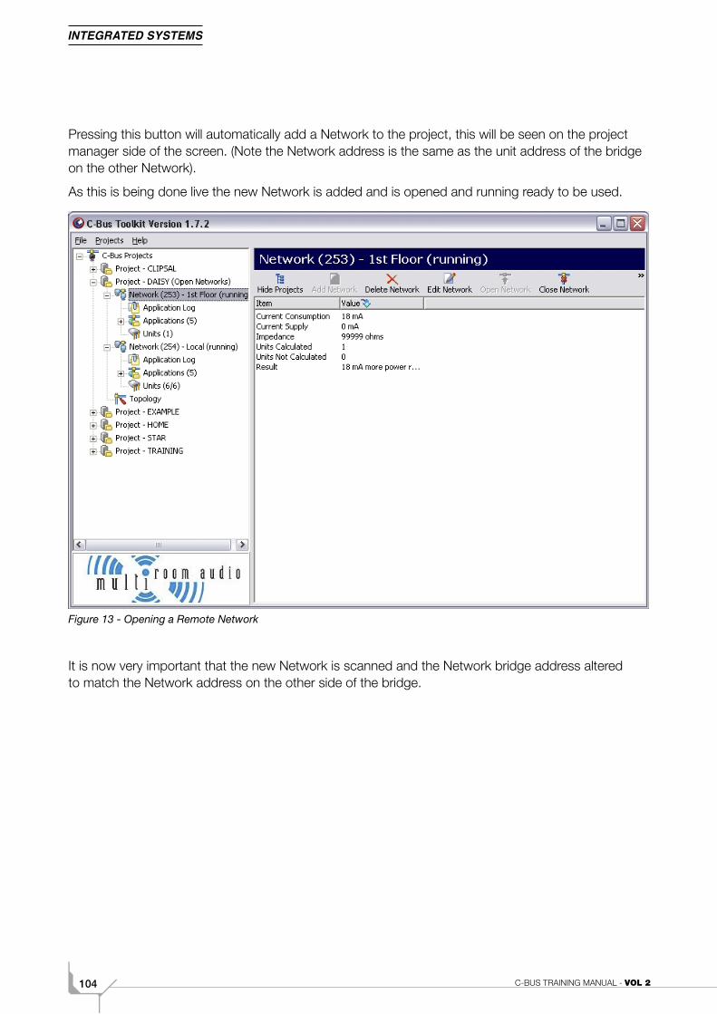
C-BUS TRAINING MANUAL - VOL 2104
Pressing this button will automatically add a Network to the project, this will be seen on the project manager side of the screen. (Note the Network address is the same as the unit address of the bridge on the other Network).
As this is being done live the new Network is added and is opened and running ready to be used.
Figure 13 - Opening a Remote Network
It is now very important that the new Network is scanned and the Network bridge address altered to match the Network address on the other side of the bridge.
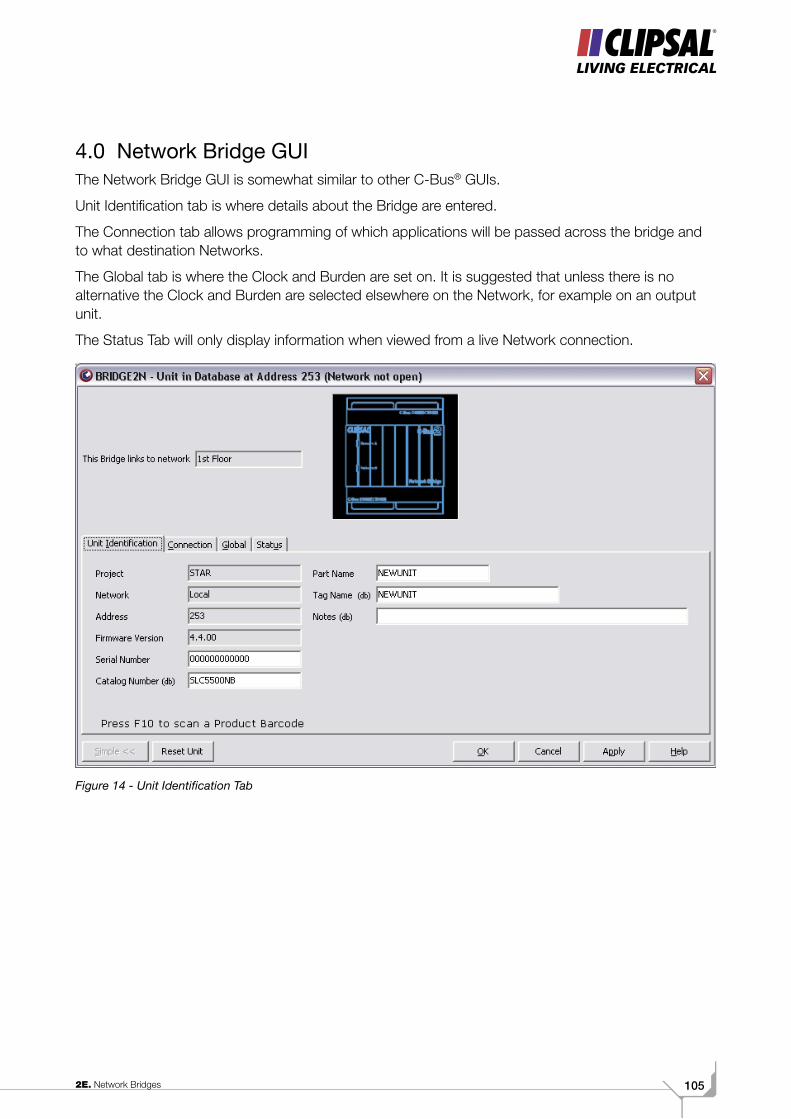
1052E. Network Bridges
4.0 Network Bridge GUIThe Network Bridge GUI is somewhat similar to other C-Bus® GUIs.
Unit Identification tab is where details about the Bridge are entered.
The Connection tab allows programming of which applications will be passed across the bridge and to what destination Networks.
The Global tab is where the Clock and Burden are set on. It is suggested that unless there is no alternative the Clock and Burden are selected elsewhere on the Network, for example on an output unit.
The Status Tab will only display information when viewed from a live Network connection.
Figure 14 - Unit Identification Tab

C-BUS TRAINING MANUAL - VOL 2106
4. 1 Connection Tab
Figure 15 - Connections Tab
4.2 This Bridge links to Network
This option shows which Network the other side of the bridge is physically connected to.
4.3 Connect ApplicationsThe default setting of the bridge is to allow all applications to pass through the bridge, however if you do not want to send all applications through the Network it is possible to send just two Applications through the bridge.
4.4 Message Destination If ‘Send to adjacent Network’ is selected the messages will be sent to the Network the bridge is connected to.
If ‘Send to other remote Network’ is selected it is possible to send the messages through a second bridge or a series of bridges to a remote Network.
The user can choose which Network the messages are being sent to.
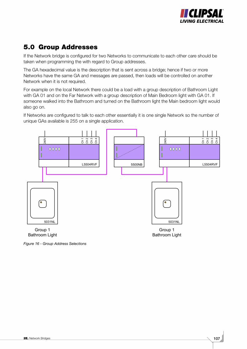
1072E. Network Bridges
5.0 Group AddressesIf the Network bridge is configured for two Networks to communicate to each other care should be taken when programming the with regard to Group addresses.
The GA hexadecimal value is the description that is sent across a bridge; hence if two or more Networks have the same GA and messages are passed, then loads will be controlled on another Network when it is not required.
For example on the local Network there could be a load with a group description of Bathroom Light with GA 01 and on the Far Network with a group description of Main Bedroom light with GA 01. If someone walked into the Bathroom and turned on the Bathroom light the Main bedroom light would also go on.
If Networks are configured to talk to each other essentially it is one single Network so the number of unique GAs available is 255 on a single application.
Figure 16 - Group Address Selections
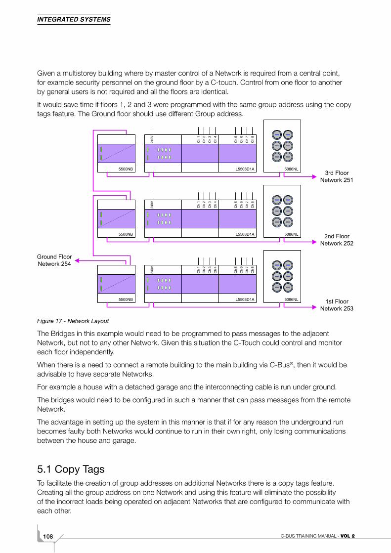
C-BUS TRAINING MANUAL - VOL 2108
Given a multistorey building where by master control of a Network is required from a central point, for example security personnel on the ground floor by a C-touch. Control from one floor to another by general users is not required and all the floors are identical.
It would save time if floors 1, 2 and 3 were programmed with the same group address using the copy tags feature. The Ground floor should use different Group address.
Figure 17 - Network Layout
The Bridges in this example would need to be programmed to pass messages to the adjacent Network, but not to any other Network. Given this situation the C-Touch could control and monitor each floor independently.
When there is a need to connect a remote building to the main building via C-Bus®, then it would be advisable to have separate Networks.
For example a house with a detached garage and the interconnecting cable is run under ground.
The bridges would need to be configured in such a manner that can pass messages from the remote Network.
The advantage in setting up the system in this manner is that if for any reason the underground run becomes faulty both Networks would continue to run in their own right, only losing communications between the house and garage.
5.1 Copy TagsTo facilitate the creation of group addresses on additional Networks there is a copy tags feature. Creating all the group address on one Network and using this feature will eliminate the possibility of the incorrect loads being operated on adjacent Networks that are configured to communicate with each other.

1092E. Network Bridges

C-BUS TRAINING MANUAL - VOL 2110
Volume 2FFault Finding
1112F. Fault Finding
Scope
This manual aims to provide an installer with the basic understanding on how to fault find a basic
C-Bus installation.
Learning Outcomes
By the end of this module, you should be competent in:
• Identifying simple software and hardware faults
• Resolving simple software and hardware faults.
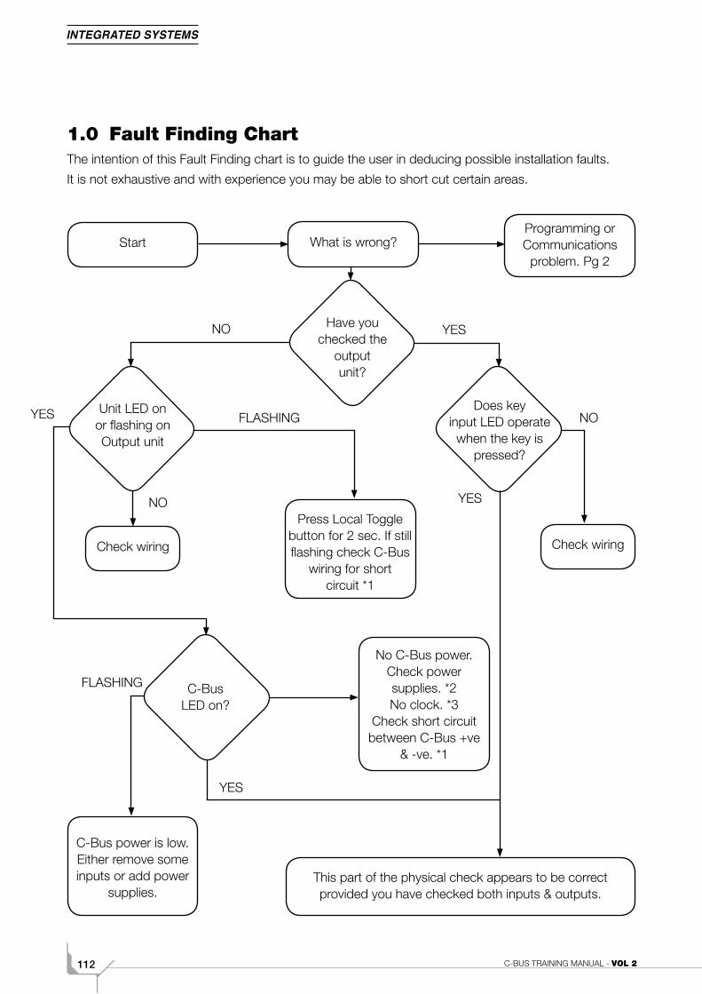
C-BUS TRAINING MANUAL - VOL 2112
1.0 Fault Finding ChartThe intention of this Fault Finding chart is to guide the user in deducing possible installation faults.
It is not exhaustive and with experience you may be able to short cut certain areas.
Start What is wrong?Programming or Communications
problem. Pg 2
Have you checked the
output unit?
Unit LED on or flashing on Output unit
Does key input LED operate
when the key is pressed?
Check wiringCheck wiring
Press Local Toggle button for 2 sec. If still flashing check C-Bus
wiring for short circuit *1
No C-Bus power. Check power supplies. *2 No clock. *3
Check short circuit between C-Bus +ve
& -ve. *1
C-Bus LED on?
C-Bus power is low. Either remove some inputs or add power
supplies.This part of the physical check appears to be correct provided you have checked both inputs & outputs.
YESNO
YES
NO
FLASHING
YES
NO
FLASHING
YES
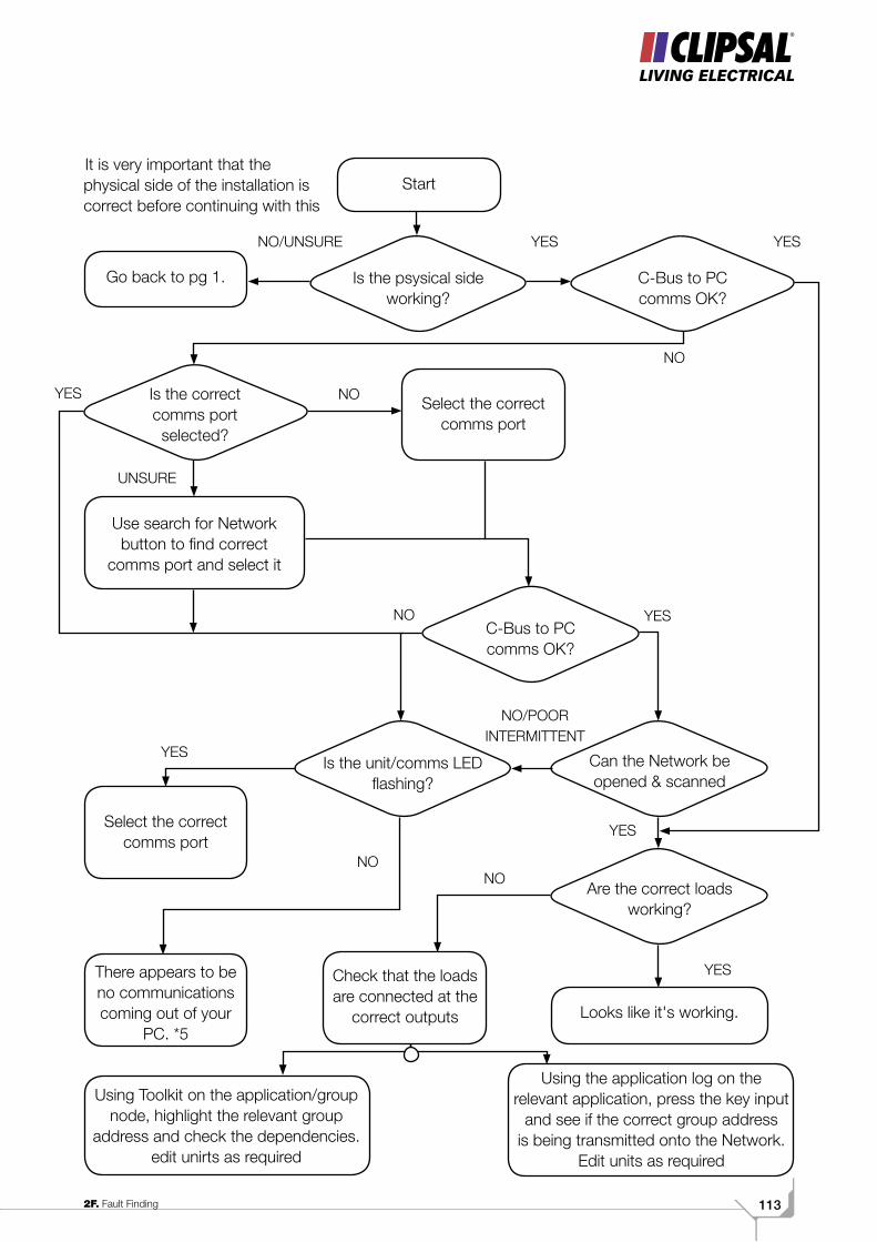
1132F. Fault Finding
Start
Go back to pg 1.
YES
NO
Is the psysical side working?
C-Bus to PC comms OK?
Is the correct comms port selected?
Select the correct comms port
YES
Use search for Network button to find correct
comms port and select it
C-Bus to PC comms OK?
Is the unit/comms LED flashing?
Can the Network be opened & scanned
Select the correct comms port
NO/UNSURE
NO/POOR INTERMITTENT
Are the correct loads working?
Looks like it's working.
There appears to be no communications coming out of your
PC. *5
Check that the loads are connected at the
correct outputs
Using Toolkit on the application/group node, highlight the relevant group
address and check the dependencies. edit unirts as required
Using the application log on the relevant application, press the key input
and see if the correct group address is being transmitted onto the Network.
Edit units as required
It is very important that the physical side of the installation is correct before continuing with this
YES
NO YES
UNSURE
YES
NONO
YES
NO
YES
C-BUS TRAINING MANUAL - VOL 2114
1.1 Fault Finding Notes
Note *1
Checking the Pink cat 5 between C-Bus positive (Blue and Orange) and Negative (Blue/white and Orange/white). Use a multimeter start on the DC voltage range to confirm there is no voltage . Then change to the ohms range, and break the circuit down in to segments until the short can be identified.
If the Unit LED is flashing, check for short circuit between C-Bus negative and Brown/Brown-White and C-Bus negative and Green/Green-White.
Note *2
Power supply units check that there are sufficient Power supplies to power the system.
Din rail output unit with power provide 200 mA
Din rail stand alone PSU provides 350 mA
Pro series dimmers provide 60 mA
Typical current demands are:
• PCI =32 mA
• PIR’s =18 mA
• Neo type Key Input =22 mA
• Standard Key input = 18 mA
• Mono touch screen = 40 mA
• Colour touch screen = 22 mA
Note *3
If there is no clock present on a C-Bus2 system, and you do not have an alternative device capable of generating a clock (with its clock enabled) that may be connected to the system then, use learn mode to enable the clock. Enter learn mode and wait until the unit light and C-Bus light flash alternatively. This may take a while if after one minute the lights are not flashing alternatively then come out of learn mode and try again.
Note *4
Confirm you have one burden if suggested by toolkit, (as a general guide if you have less than 70 units you will need one burden).
If you do not have a hardware burden on the network and it appear to have communications problems, adding a burden may help. If possible add a hardware burden, if not, a software burden may be enabled using learn mode.
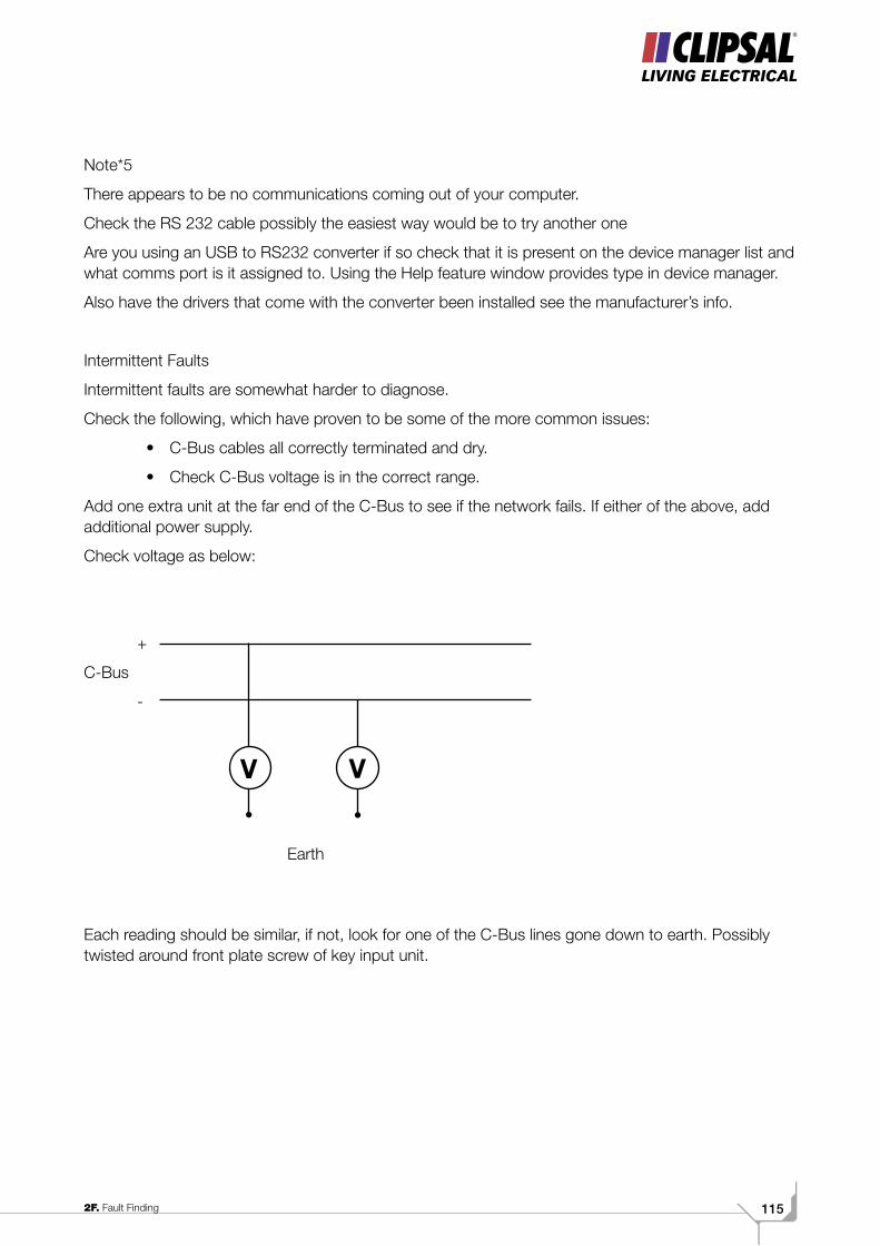
1152F. Fault Finding
Note*5
There appears to be no communications coming out of your computer.
Check the RS 232 cable possibly the easiest way would be to try another one
Are you using an USB to RS232 converter if so check that it is present on the device manager list and what comms port is it assigned to. Using the Help feature window provides type in device manager.
Also have the drivers that come with the converter been installed see the manufacturer’s info.
Intermittent Faults
Intermittent faults are somewhat harder to diagnose.
Check the following, which have proven to be some of the more common issues:
• C-Bus cables all correctly terminated and dry.
• Check C-Bus voltage is in the correct range.
Add one extra unit at the far end of the C-Bus to see if the network fails. If either of the above, add additional power supply.
Check voltage as below:
+
C-Bus
-
Each reading should be similar, if not, look for one of the C-Bus lines gone down to earth. Possibly twisted around front plate screw of key input unit.
V V
Earth
C-BUS TRAINING MANUAL - VOL 2116
Advanced 17
Application Addresses 23
Backup Project Repository 17
Close All Networks 18 Export Projects 18
Group Addresses 16
Groups 24
Hardware 12
Help Menu 18
Import Projects 18
Installing the Software 13
Interface Default 15Level Set Group On 16
Network 21
Operating System 12
Preferences 16
Repository 15
Restore Project Repository 17
Scan Network 18
Scanning a New C-Bus® Network 29
Search for Networks 18
Starting the Program 14
Topology 28
Units 26
Index Volume 2A. C-Bus® Toolkit Software
Index Volume 2B. Basic Programming
C-Bus® Light Level Sensor Programming 47
C-Bus Wall Switch 45 Functions 45
Day Time Movement Detection 50
Functions
Bell Press 46
Custom 46
Dimmer 46
Dimmer Down 46
Dimmer Up 46
Off 46
Off Down 46
On 46 On Up 46
On/Off 46
Preset 1 46
Preset 2 46
Scene 4 46
Soft Down 46
Soft Up 46
Timer 46
Trigger 1 46
Trigger 2 46
Unused 46
PIR Functions 45
PIR Occupancy Sensor Programming 49
Scene 75
Voltage Free Relay 54
1172E. Network Bridges
Index Volume 2C. Advanced Programming
AND Logic 56
Blocks Tab 69
Debounce 63
Restrike 59
Disable All Keys 64
DownCycle 67
Down Key 67
ENDRAMP 68
Environment Tab 73
Expiry Command 69
Global 60
Global Tab 63
Indicators Tab 70
Infra-Red Setting 64
Key Functions Tab 66
Learn Mode 64
Logic 56
Long Press Time 63
Neo® 62
Off Key 68
OR Logic 56
Power Fail Tab 64
Programming the Neo 76
RAMP OFF 68
Ramp Time 1 63
Ramp Time 2 64
Recovery 58
Relay Units 54
Restrike Delay 59
Scene Saving the Scene 80 Creating 78
Scene Control 75
Scenes Tab 72
Status 74 Status Report 64
Turn On 55
Unit Identification 55
UPKEY 67
Voltage Free Relay 54
C-BUS TRAINING MANUAL - VOL 2118
Applications 85
Blocks tab 87
Disable All Keys 86
Dynamic Labelling 84
Global Tab 86
GUI 85
Indicators tab 88
Labelling 89
Labelling Scenes 91
Time 92
Index Volume 2D. Dynamic Labelling
Index Volume 2E. Network Bridges
Add Additional Networks 105
Input Units 111
Network Bridge 109
Network Topology 99
Output Units 111
Status Report 97
Index Volume 2F. Fault Finding
Fault Finding Chart 120
Fault Finding Notes 116

1192C. Advanced Programming
Index Volume 2F. Fault Finding
C1-
007
O/N 14934CLIPCOM 14934 The identified trademarks and copyrights are the property of Clipsal Australia Pty Ltd unless otherwise noted.
Product of Clipsal Australia Pty LtdA member of the Schneider Electric Group
Head Office 12 Park Terrace, Bowden South Australia 5007 Telephone (08) 8269 0511 Facsimile (08) 8340 1724 Internet clipsal.com E-Mail [email protected]
National Customer Service Enquiries: 1300 2025 25National Customer Service Facsimile: 1300 2025 56Area Representatives NSW Albury (02) 6051 2377 Central 0418 430 361 Coffs Harbour 0418 653 183 Dubbo 0418 822 564 Newcastle 0407 298 792 0418 434 169 0418 686 040 0417 201 115 Tamworth 0417 714 339 Wagga Wagga 0418 578 903 Wollongong 0418 423 581
ACT Canberra region 0408 550 373
VIC Ballarat 0418 336 291 Bendigo 0418 570 213 Geelong 0418 527 233 Gippsland 0418 512 680 Mornington Peninsula 0407 795 291 Western Victoria 0419 380 444
QLD Cairns 0418 778 499 Gladstone 0419 869 752 Gold Coast 0417 863 872 Mackay 0418 752 134 Maryborough 0418 664 338 Northern Rivers 0418 768 902 Rockhampton 0419 869 752 Sunshine Coast Nth 0419 797 827 Sunshine Coast Sth 0438 282 299 Toowoomba 0418 726 394 Townsville 0418 180 372
WA Bunbury 0418 931 684 Kalgoorlie and Eastern Gold Fields 0417 928 981 Karratha 0418 937 249
SA Riverland/Mildura/ Broken Hill 0418 596 145
NT Darwin 0409 282 307
TAS North 0418 120 269 South 0418 138 456
Clipsal Australia Pty Ltd reserves the right to change specifications, modify designs and discontinue items without incurring obligation and whilst every effort is made to ensure that descriptions, specifications and other information in this catalogue are correct, no warranty is given in respect thereof and the company shall not be liable for any error therein.
You can find this brochure and many others online in PDF format at: clipsal.comFollow the links off the home page or access the following page directly: clipsal.com/wat_lib_pdf.cfm
International Enquiries
International Sales and Marketing Telephone + 61 8 8269 0587 Facsimile + 61 8 8340 7350 E-Mail [email protected]
New Zealand Clipsal Industries (NZ) Ltd Telephone (09) 576 3403 Facsimile (09) 576 1015 E-Mail [email protected]
Customer Service Free Fax (0508) 250 305 Auckland/Mobile Phone (09) 572 0014 Free Phone (0508) CLIPSAL 2547725
Training & Technical Support
Australia 1300 722 247 New Zealand 0800 888 219 International +61 8 8345 9544 Email: [email protected]
© Clipsal Australia Pty Ltd.
This material is copyright under Australian and international laws. Except as permitted under the relevant law, no part of this work may be reproduced by any process without prior written permission of and acknowledgement to Clipsal Australia Pty Ltd.
printed on recycled paper


![BUS BUS BUS BUS BUS BUS BUS BUS BUS · Sunday 15 May 2016 Liverpool Street to Colchester, Ipswich, Norwich and branches BUS BUS BUS BUS BUS BUS BUS BUS BUS] 1 1 1 1 1 1 1 1 1 1 1](https://static.fdocuments.in/doc/165x107/5fab4ce2477d2d3adf21016a/bus-bus-bus-bus-bus-bus-bus-bus-sunday-15-may-2016-liverpool-street-to-colchester.jpg)