C-BS-‘I000Series - · PDF fileThelastpanel settingis internallystored in...
2
"vi1|"vi ul :». — '.,- _ em qfl - ut = - - annular an-1au4 --mg,»-3 @ .- @ i-_ mu: >u:r'.».|. - 1.71;,-7 -:::'- :-. . . _ ‘-__.1:12: _ :=:=:; ||| Ill || '|'i'| |I,','|'l|'|i . 'rl|'il|'| I|l:|||'l* ‘ |iI*',*|'|'iiI',' l | | .¢' Q M“HW"n . . I i|il'l|';'|i|l,l" --;-. ll Ill" Hull‘ ||Qlrl"|||Il“"||ll’ . . 'i'i'I""r'Il'|"li'I'I*' 1 rl II 'r .. = .- - |'i||'|‘lli||'|;|II' .. | , -I ' -1 i> '7 GI1 I A ” 5°’ lufllflaf ' ' lwv _ ,_ . Z @ s a:.~.:1-::- - /'*' A; . LabV|EW (€ RS 232 USB Driver Pl "dge ' r I ¢======z v {Q- Q. I Summary of Features Wide selections of bandwidth, 200/I00/70MHz, 4channels, suitable for major applications in laboratories, production lines, or field services. 'IGSa/s real-time high sampling rate and 25k points deep memory give much detailed view into the target waveforms and maintain a high sampling rate. USB host and device connection allow data storage and recalling, screen image printout, and remote control. TFT color LCD display with wide viewing angle eliminates obscurity in any situation. Signal Detection The CBS-I000 series, with IGSa/s real time, 25GSa/s equivalent time sampling rate and 3 types of acquisition modes including normal, peak detect, and average, picks up signals even in the most extreme cases. 25k points deep memory collects more information ofa given waveform providing users with further signal details. 3 types offlexible triggers including edge, video (NTSC, PAL, SECAM) with line selection and pulse-width augment the signal capturing flexibility Complete Vertical and Horizontal Expansion Function Users, via the CBS-1000 Series, can either select GND or the center ofthe signal to execute vertical expansion. Either the center ofthe signal or the vertical trigger point can be selected to carry out horizontal expansion. A sound signal expansion selection facilitates users to expand required signals for a detailed observation ofsignal trigger points. Measurement Functions A variety of measurement shortcuts reduce repetitive manual operations and save your precious time. Autoset automatically configures the horizontal scale, the vertical scale, and the trigger, giving an instant view ofalmost any signal. 27 automatic measurements include voltage, freq uency(time), and delay. Once the cursor function is on, the measurement target will be the signal within the cursor. Users can measure any desired signal based upon the application requirements. The GBS-I 000 Series runs and updates results of all the relevant measurements in real time. You can view the results independently, or together in a single display view. Add, subtract and multiple math operation and with 4 types of FFT, FFTrms including flattop, blackman , hanning, and rectangular are also provided. DATA Log Data logger can continue monitoring input signals and storing their waveform data or image in a USB flash drive when trigger conditions are met. This functionality will save users‘ effort in tracking signals manually and allowing them to analyze and observe waveform data afterwards. Go/NoGo Test Function Go/NoGo test function detects an user-defined incoming waveform shape, and can also send a signal to external devices for monitoring. Program and play feature automatically runs predefined sequence and setup, boosting productivity in routine measurements like production line inspection. Data Transfer and Printout USB host connector transfers data quickly and easily between USB flash drive and the oscilloscope, which greatly expands memory via a USB. The internal storage includes 4 sets of reference waveform and 20 sets of general-use memory area. The GBS-1000 Series handles three types ofdata : display image (*.bmp) for viewing waveform shape and pasting into documents and presentations, panel setting for saving and restoring system setup, and waveform configuration (*.csv) for further analysis of signal information. Printout ofdisplay Image, color or grayscale, is available through the PictBridge- compatible Printer connected to the USB host port. You can set the printout or data saving preference to allow a single-press on Hardcopy during the consecutive works. Setup Recovery and Transfer The last panel setting is internally stored in nonvolatile memory, ready to be recovered on the next power up. Ifthe measurement environment has been frequently changed or users want to transfer the setup to another GBS~I 000 Series, switching between multiple system settings can be done by saving and recalling setup files using a USB flash drive. When the setup gets complicated, you can always recover the default system setting in a simple two-step operation. C-BS-‘I 000 Series '_ -W. .,_. E gr I H FEATURES ,' E; 3 pg ,1:I:?:i:1:i:1:?lIl:i:i ¢ 200/‘I00/70 MHz Bandwidth 0 4 Input Channels o '|C-Sa/s Real-Time and 25GS/s Equivalent-Time Sampling o 25k Points Record Length Maximum O 5.7-in TFT Color Display ' 27 Automatic Measurements 0 Math Functions Including "+" , "- " , ll xll , IIFFTII , llFFTrmsll o Multi-Language Support 0 USB Host: Support Flash Drive Storage and PictBridge-compatible Printer ' USB Device : PC Remote Control O Data Logger 5‘ E ‘T II »=.;|_ 5! . :_ ‘Bf’ r 1 1 - i .‘L‘."._'.‘F1 .IZ‘,~"i'R'u flfjfl 3-nan 1... .-. . ... u.. re I * z I Front »' _ 3 Q .» E ‘N O -ii 5 El _ . .. i A -I - -~ a | %‘.'¢ III Sto '-a A “Q f'\ fl'\ 55“ 2 I .- .r-.-= -10 -..|.--. $.II1I, .|. .-.- —r_ ii-\-.-;=..-1-rm-r. 1.‘-Q.--r-nu--1..-... -up-.r-r-em--v.-.-----.‘v--~--.. 0 _ Q T T Rear Panel APPLICATIONS ' Education Lab and Training Institution ~ Production Test and Quality Inspection ' Repair and After-Service ° Circuit Design and Debugging G‘! ll'l5l'EK Simply Reliable
Transcript of C-BS-‘I000Series - · PDF fileThelastpanel settingis internallystored in...

"vi1|"viul:».—
'.,-
_
em qfl
- ut = - -annular an-1au4 --mg,»-3 @ .- @i-_ mu: >u:r'.».|.
- 1.71;,-7 -:::'- :-. . . _ ‘-__.1:12:
_:=:=:;
||| Ill ||'|'i'| |I,','|'l|'|i
. 'rl|'il|'| I|l:|||'l*‘ |iI*',*|'|'iiI','l | |.¢' Q M“HW"n. . I i|il'l|';'|i|l,l"--;-.
llIll" Hull‘||Qlrl"|||Il“"||ll’
. . 'i'i'I""r'Il'|"li'I'I*'1rl II 'r.. = .- - |'i||'|‘lli||'|;|II'
.. |, -I
' -1
i>'7 GI1
I A ”5°’ lufllflaf ' 'lwv _ ,_ .Z @ s a:.~.:1-::- - /'*'A; .
LabV|EW(€ RS 232 USB Driver Pl "dge
' r
I
¢======z v {Q-
Q.I
Summary of FeaturesWide selections of bandwidth, 200/I00/70MHz,4channels, suitable for major applications inlaboratories, production lines, or field services.'IGSa/s real-time high sampling rate and 25k pointsdeep memory give much detailed view into thetarget waveforms and maintain a high samplingrate. USB host and device connection allow datastorage and recalling, screen image printout, andremote control. TFT color LCD display with wideviewing angle eliminates obscurity in any situation.
Signal DetectionThe CBS-I000 series, with IGSa/s real time,25GSa/s equivalent time sampling rate and 3 typesof acquisition modes including normal, peak detect,and average, picks up signals even in the mostextreme cases. 25k points deep memory collectsmore information ofa given waveform providingusers with further signal details. 3 types offlexibletriggers including edge, video (NTSC, PAL, SECAM)with line selection and pulse-width augment thesignal capturing flexibility
Complete Vertical and HorizontalExpansion FunctionUsers, via the CBS-1000 Series, can either selectGND or the center ofthe signal to execute verticalexpansion. Either the center ofthe signal or thevertical trigger point can be selected to carry outhorizontal expansion. A sound signal expansionselection facilitates users to expand required signalsfor a detailed observation ofsignal trigger points.
Measurement FunctionsA variety of measurement shortcuts reducerepetitive manual operations and save yourprecious time. Autoset automatically configuresthe horizontal scale, the vertical scale, and thetrigger, giving an instant view ofalmost any signal.27 automatic measurements include voltage,freq uency(time), and delay. Once the cursorfunction is on, the measurement target will be thesignal within the cursor. Users can measure anydesired signal based upon the applicationrequirements. The GBS-I 000 Series runs andupdates results of all the relevant measurementsin real time. You can view the results independently,or together in a single display view. Add, subtractand multiple math operation and with 4 types ofFFT, FFTrms including flattop, blackman , hanning,and rectangular are also provided.
DATA LogData logger can continue monitoring input signalsand storing their waveform data or image in a USBflash drive when trigger conditions are met. Thisfunctionality will save users‘ effort in trackingsignals manually and allowing them to analyzeand observe waveform data afterwards.
Go/NoGo Test FunctionGo/NoGo test function detects an user-definedincoming waveform shape, and can also send asignal to external devices for monitoring. Programand play feature automatically runs predefinedsequence and setup, boosting productivity inroutine measurements like production lineinspection.
Data Transfer and PrintoutUSB host connector transfers data quickly andeasily between USB flash drive and theoscilloscope, which greatly expands memory via aUSB. The internal storage includes 4 sets ofreference waveform and 20 sets of general-usememory area. The GBS-1000 Series handles threetypes ofdata : display image (*.bmp) for viewingwaveform shape and pasting into documents andpresentations, panel setting for saving andrestoring system setup, and waveformconfiguration (*.csv) for further analysis of signalinformation. Printout ofdisplay Image, color orgrayscale, is available through the PictBridge-compatible Printer connected to the USB host port.You can set the printout or data saving preferenceto allow a single-press on Hardcopy during theconsecutive works.
Setup Recovery and TransferThe last panel setting is internally stored innonvolatile memory, ready to be recovered on thenext power up. Ifthe measurement environmenthas been frequently changed or users want totransfer the setup to another GBS~I 000 Series,switching between multiple system settings canbe done by saving and recalling setup files usinga USB flash drive. When the setup getscomplicated, you can always recover the defaultsystem setting in a simple two-step operation.
C-BS-‘I 000 Series'_ -W. .,_. E gr I H FEATURES
,' E;3 pg ,1:I:?:i:1:i:1:?lIl:i:i¢ 200/‘I00/70 MHz Bandwidth
0 4 Input Channels
o '|C-Sa/s Real-Time and 25GS/sEquivalent-Time Sampling
o 25k Points Record Length MaximumO 5.7-in TFT Color Display
' 27 Automatic Measurements
0 Math Functions Including "+" , "- " ,ll xll , IIFFTII , llFFTrmsll
o Multi-Language Support
0 USB Host: Support Flash Drive Storageand PictBridge-compatible Printer
' USB Device : PC Remote ControlO Data Logger
5‘ E‘T
II»=.;|_5! .:_‘Bf’
r 1
1 - i .‘L‘."._'.‘F1 .IZ‘,~"i'R'uflfjfl3-nan 1... .-. . ... u . . re
I * z I
Front
»' _3 Q .» E ‘N O-ii 5 El
_ . .. i A -I
- -~a |%‘.'¢III Sto'-a A“Q f'\ fl'\ 55“ 2 I.- .r-.-= -10 -..|.--. $.II1I, .|. .-.-
—r_ ii-\-.-;=..-1-rm-r.1.‘-Q.--r-nu--1..-...-up-.r-r-em--v.-.-----.‘v--~--..0 _ Q
T T
Rear Panel
APPLICATIONS
' Education Lab and Training Institution
~ Production Test and Quality Inspection
' Repair and After-Service
° Circuit Design and Debugging
G‘! ll'l5l'EKSimply Reliable
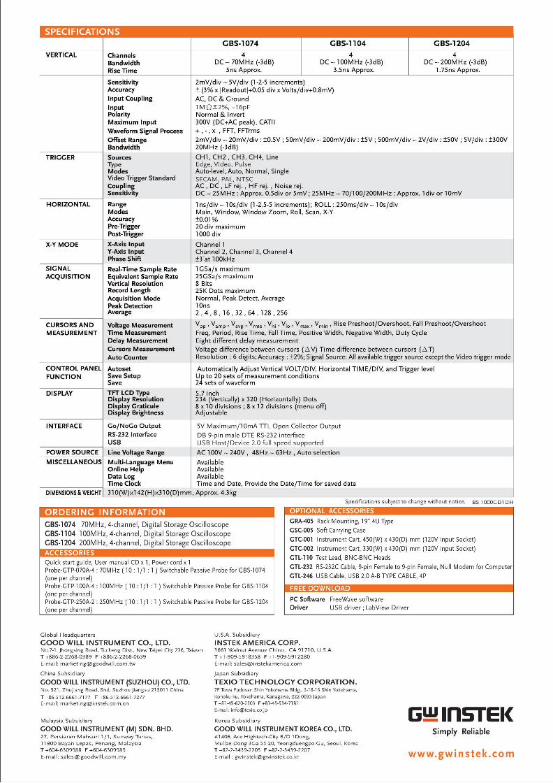
SPECIFICATIONSGBS-‘I O74 GBS-11 O4 GBS-1204
VERTICAL ChannelsBandwidthRise Time
4 4 4DC ~ 70MHz (~3dB) DC ~ 100MHz (~3dB) DC ~ 200MHz (-3dB)
5ns Approx. 3.5ns Approx. 'I.75ns Approx.
TRIGGER
HORIZONTAL
X-Y MODE
SIGNALACQUISITION
CU RSORS AN DM EASU REM ENT
CONTROL PANELFUNCTION
DISPLAY
INTERFACE
POWER SOURCEMISCELLANEOUS
DIMENSIONS 3i. WEIGHT
SensitivityAccuracylnputCbupfingInputPolarityMaximum InputWaveform Signal ProcessOffset RangeBandwidth-SourcesTypeModesVideo Trigger StandardCouplingSensitivity
RangeModesAccuracyPre-TriggerPost-TriggerX-Axis InputY-Axis InputPhase ShiftReal-Time Sample RateEquivalent Sample RateVertical ResolutionRecord LengthAcquisition ModePeak DetectionAverage
Voltage MeasurementTime MeasurementDelay MeasurementCursors MeasurementAuto CounterAutosetSave SetupSaveTFT LCD TypeDisplay ResolutionDisplay GraticuleDisplay Brightness
Go/NoC-o OutputRS-232 InterfaceUSB
Multi-Language MenuOnline HelpData LogTime Clock Time and Date, Provide the Date/Time for saved data
2mV/div ~ 5V/div (I-2-5 increments)i (3% x |Readout|+0.05 div x Volts/div+0.8mV)AC, DC 81. GroundIMQi2%, ~16pFNormal & Invert300v (DC+AC peak), CATII+ , - , X , FFT, FFT|'!"l'1S2mV/div ~ 20mV/div 1 :o.5v ; 50mV/div ~ 200mV/div ; i5V ; 500mV/div ~ 2V/div = i-50V ; 5V/div : i300V20MHz (-3dB)CHI, CH2 , CH3, CH4, LineEdge, Video, PulseAuto-level, Auto, Normal, SingleS ECAM, PAL, NTSCAC, DC , LF rej. , HF rej. , Noise rej.DC ~ 25MHz : Approx. 0.5div or 5mV; 25MHz ~ 70/‘I 00/200M Hz : Approx. Idiv or I0mV
Ins/div--10s/div (I-2.5-5 increments); ROLL: 250ms/div~ 10s/divMain, Window, Window Zoom, Roll, Scan, X-Yi0.0I%20 div maximumI000 divChannel IChannel 2, Channel 3, Channel 4i3°at 100kHzIGSa/s maximum25GSa/s maximum8 Bits25K Dots maximumNormal, Peak Detect, AverageI0ns2,4,3,16,32,64,128,256
V , V ,V V V , V ,V V Rise Preshoot/Overshoot Fall Preshoot/Overshootpp amp avg’ rms ' hi Io maxi min I IFreq, Period, Rise Time, Fall Time, Positive Width, Negative Width, Duty CycleEight different delay measurementVoltage difference between cursors (AV) Time difference between cursors (AT)Resolution : 6 digits; Accuracy : i2%; Signal Source: All available trigger source except the Video trigger mode
Automatically Adjust Vertical VOLT/DIV, Horizontal TI ME/DIV, and Trigger levelUp to 20 sets of measurement conditions24 sets ofwaveform5.7 inch234 (Vertically) x 320 (Horizontally) Dots8 x 10 divisions ; 8 x I2 divisions (menu off)Adjustable
5V Maximum/10mA TTL Open Collector OutputDB 9-pin male DTE RS-232 interfaceUSB Host/Device 2.0 full speed supported
Line Voltage Range AC IOOV ~ 240V , 48Hz ~ 63 Hz , Auto selectionAvailableAvailableAvailable
3'I0(W)><142(H)><310(D)mm, Approx. 4.3kg
GBS I074 70MHz, 4 channel, Digital Storage OscilloscopeGBS 1104 100MHz, 4 channel, Digital Storage OscilloscopeGBS-1204 200MHz, 4-channel, Digital Storage OscilloscopeACCESSORIESQuick start guide, User manual CD x I, Power cord x IProbe-GTP-070A-4 : 70M Hz (10: 1/I : 1 ) Switchable Passive Probe for GBS-1074(one per channel)Probe-GTP-100A-4 : 100MHz ( I0 : I/I :1 ) Switchable Passive Probe for CBS-I104(one per channel)Probe-GTP-250A-2 : 250MHz (10: 1/1 : 1 ) Switchable Passive Probe for CBS-1204(one per channel)
ORDERING INFORMATION
FREE DOWN LOAD
Specifications subject to change without notice. B5-1()00(j.[)‘| [)|-|
OPTIONAL ACCESSORIESGRA-405 Rack Mounting, 19" 4U TypeGSC-005 Soft Carrying CaseGTC-001 Instrument Cart, 450(W) x 430( ) mm (I20V Input Socket)GTC-002 Instrument Cart, 330(W) x 430( ) mm (120V Input Socket)GTL-110 Test Lead, BNC-BNC HeadsGTL-232 RS-232C Cable, 9-pin Female to 9-pin Female, Null Modem for ComputerGTL-246 USB Cable, USB 2.0 A-B TYPE CABLE, 4P
UU
PC Software FreeWave softwareDriver USB driver ;LabView Driver
Global Headquarters U.S.A. SubsidiaryGOOD WILL INSTRUMENT CO., LTD. INSTEK AMERICA CORP.No.7-1, jhongsing Road, Tucheng Dist., New Taipei City 236, Taiwan 3661 Walnut Avenue Chino, CA 91710, U.S.A.T +836-2-2253-0339 F +836-2-2263-0639 T +1 -909-591 8353 F +1 -909-591 2280E-mail: [email protected] E-mail: [email protected]
China Subsidiary japan Subsidiary
GOOD WILL INSTRUMENT (SUZHOU) CO., LTD. TEXIO TECH NOLOCY CORPORATION.No. 521, Zhujiang Road, Snd, Suzhou jiangsu 215011 China 7F Towa Fudosan Shin Yokohama Bldg., 2-13-13 Shin Yokohama,T +86-512-6661-7177 F +86-512-6651-7277 Kohoku-ku. Yokohama. Kanagawa 222-0033 JapanE-mail: l"|’l3I'l(EtlI'lg@)lflSlIEI(.COITl.Cl‘| T +81-45-620-2303 F +81-45-534-7181
E-mail‘ info@texio co jp G"-I Il'l5I'EKMalaysia Subsidiary Korea Subsidiary icoon WILL INSTRUMENT (M) SDN. BHD. coon WILL INSTRUMENT KOREA co., LTD. 5imp|y Re|;ab|e27, Persiaran Mahsuri 1/1, Sunway Tunas, #1406, Ace Hightech-City B/D1D0ng,11900 Bayan Lepas, Penarig, Malaysia Mullae-Dong 3Ga 55-20, Yeongduengpo-Cu, Seoul, KoreaT +604~630998S F +604~6309939 T +82-2-3439-2205 F +82-2-3439-2207 vE-mail: [email protected] E-rnail : [email protected] W W W‘ In S k ' C 0 m