C AUT rON - VTDA
78
ALTOS COMPUTER SYSTEMS ACS 8000-12 OR AN ACS COMPUTER SYSTEM USER MANUAL C AUT rON Altos Equipment, when installed as defined within this manual, is intended for use as a Class A computing device subject to FCC Rules, Part 15., Subpart J. The equipment is used under temporary permit while awaiting completion of testing for compliance with FCC Rules. These Rules ensure reasonable protection from radio emissions that can interfer with normal reception by radio c o· mmuni cat ion s de vice s• Sh 0 U1 dan y interference occur, the user of this equipment will be required to take corrective measures at his own expense.
Transcript of C AUT rON - VTDA

ALTOS COMPUTER SYSTEMS
ACS 8000-12 OR AN ACS 8~~0-l4
COMPUTER SYSTEM
USER MANUAL
C AUT rON
Altos Equipment, when installed as definedwithin this manual, is intended for use as aClass A computing device subject to FCC Rules,Part 15., Subpart J. The equipment is usedunder temporary permit while awaitingcompletion of testing for compliance with FCCRules. These Rules ensure reasonableprotection from radio emissions that caninterfer with normal reception by radioc o· m m u n i cat ion s d e vice s • S h 0 U1 dan yinterference occur, the user of this equipmentwill be required to take corrective measures athis own expense.

PRE F ACE
This manual is divided into two parts.
Part One presents hardware installationprocedures and diagnostics tests andutilities. The diagnostic tests should be runwhenever the ALTOS ACS 8000-12 or an ACS 800014 system is set up or reconfigured.
Part Two presents hardware specifications andcircuit schematics for the ALTOS 8500 CPU, theHard Disk Controller Board, the TapeController Board, and the I/O PortAssignments. This section does not normallyneed to be consulted during initial system setup.
The Table of Contents for Part Two repeatsstarting after Part One, page 2-35.
J
•'-./
'-..../

SECTION
l-
1.11.1.11.21.2.11.2.21.31.41.4.11.4.21.4.31.51.6
1.6.11.6.2
1.6.31.6.41.6.51.6.61.6.71.6.81.71.7.11.7.21.7.3
1.7.4
2.
2.12.1.12.22.32.42.52.62.72.8
/"-2_92.102.112.12
TABLE. Of CONTENTS
TITLE
PART ONE
INTRODUCT ION •••••••••••••••••••••••••••••••••••••
Unpacking and Installing your Computer •••••••••••Unpacking your Computer ••••••••••••••••••••••••••Installation and Checkout ••••••••••••••••••••••••Console and Printer Connections ••••••••••••••••••Disk Insertion ....................•..............Packing and Shipping •••••••••••••••••••••••••••••Bringing up your Computer System •••••••••••••••••System Power-On •.....•••......•••...•••••••••••••Initial Console Display •••.•••••.••••••••.•••••••System Power-Down ••••••••••••••••••••••••••••••••Floppy Disk Drive Identification •••••••••••••••••OASIS Operating System Installation onACS 8000-12, ACS 8000-14, Add-12 and Add-14Computer s ••••••••••••••••••••••••••••••••••••••••Hard Disk Formatting and Initialization ••••••••••Initialize the ACS 8000-12, ACS 8000-14 ComputerHard Disk ••••••••••••••••••••••••••••••••••••••••Adding a 20- or 40- Mbyte Hard Disk ••••••••••••••OASIS Update Information •••••••••••••••••••••••••Code Terminal ..........•....•••.•............••..INITDISK Command •••••••••••••••••••••••••••••••••Sector Spar ing .................•...•...•.•.•.•..•BOOIJWR I T Command •••••••••••••••••••••••••••••••••System Configuration •••••••••••••••••••••••••••••Hardware Configuration Jumper Block ••••••••••••••Software Configuration Jumper Block ••••••••••••••MUlti-user/Networking Port Configuration JumperBlock .....................•........••..•.....••..Eight-inch Hard Disk Controller ••••••••••••••••••
ALTOS DIAGNOSTIC EXECUTIVE (ADX) VERSION 2.4F
Diagnostic Command Categories ••••••••••••••••••••SETUP/FORMAT/COPY UTILITIES ••••••••••••••••••••••ADXSETUP Utility •••••••••••••••••••••••••••••••••FLPYFORM utility •.••••.•••••.••••••••••••••••••••BOOTCOPY utility - One Floppy Disk Drive •••••••••FLPY utility •••.••••.•••.•••••••••••••.••••••••••SYSTEM AND FLOPPY DRIVE TESTS ••••••••••••••••••••CPUTST85 •••••••••••••••••••••••••••••••••••••••••FLPYTEST Utility •.••.•.•••••.•••••••••.•••.••••••PRNTEST •.......... - - - - - - - - - - - - - - - T - •••••••
MEMTES T ••••••••••••••••••••••••••••••••••••••••••DISKSTAT •••••••••••••••••••••••••••••••••••••••••Hard Disk Tests and Functions ••••••••••••••••••••
i
PAGE
1-1
1-31-31-61-61-61-9
1-101-101-101-111-12
1-131-13
1-151-171-191-231-241-261-281-311-311-31
1-311-31
2-1
2-22-22-32-62-82-9
2-122-122-132-15
2-162-172-18

SECTION
2.132.13.12.13.22.13.32.13.42.13.52.13.62.13.72.13.82.13.92.13.102.13.112.13.12
TABLB OF CONTBNTS
TITLB
PABTOBB
Hard Disk (8") Test Facility, V3.4 •••••••••••••••Forma t Disk Dr i ve ••••••••••••••••••••••••••••••••Verify Addresses for all sectors on Disk •••••••••Seek Test with Optional Verify •••••••••••••••••.•Write Entire Disk ••••••••••••••••••••••••••••••••Read Entire Disk •••••••••••••••••••••••••••••••••Set Flag Byte for a Specific Sector ••••••••••••••Hard Disk Read/Write Error Test ••••••••••••••••••Miscellaneous Functions ••••••••••••••••••••••••••Hard Test 9 - Copy Diagnostics to Hard Disk ••••••Hard Test 10 - Initialize Hard Disk System Track •Hard Test 11 - Copy System to Hard Disk ••••••••••Hard Test 12 - Assign Diagnostic Area ••••••••••••
II
~
2-192-202-212-222-232-242-262-272-302-322-332-342-35
J
'-..-/
'-..-/

SECTION
1.
2.
2.12.22.32.42.52.62.7
3.
3.13.1.13.1.23.1.33.23.33.3.13.3.23.43.53.6
TABLE or CONTENTS
TITLE
PART TWO
8500 CENTRAL PROCESSING UNIT PRINTED CIRCUIT BOARDAND THE 8" HARD DISK CONTROLLER BOARD ••••••••••••
THE 8500 CPU PRINTED CIRCUIT BOARD (PCB) •••••••••
Memory •••••••••••••••••••••••••••••••••••••••••••The Hard Disk Controller (HDC) •••••••••••••••••••Floppy Disk Controller (FDC) •••••••••••••••••••••Magnetic Tape Unit Controller ••••••••••••••••••••I/O Port Assignments for the 8500 PCB ••••••••••••Z80 Interrupt Daisy Chain ••••••••••••••••••••••••ALTOS Interface Connector Wiring •••••••••••••••••
ALTOS 8" HARD DISK CONTROLLER, MTU CONTROLLER, ANDTHE SHUGART 8" SOFT-SECTORED DRIVE •••••••••••••••
8" Hard Disk Controller ••••••••••••••••••••••••••Commands/Command Por ts •••••••••••••••••••••••••••Status/Status Port •••••••••••••••••••••••••••••••Ports 022H and 02lH ••••••••••••••••••••••••••••••Forma t ting •••••••••••••••••••••••••••••••••••••••Reading or Writing a Sector ••••••••••••••••••••••Reading a Sector •••••••••••••••••••••••••••••••••Writing a Sector •••••••••••••••••••••••••••••••••Controller Responses •••••••••••••••••••••••••••••Shugart 8" Soft-Sectored Drive •••••••••••••••••••Magnetic Tape Controller •••••••••••••••••••••••••
SCHEMATICS
PAGE
1-1
2-1
2-12-12-12-32-3
2-102-11
3-1
3-13-63-7
3-103-113-133-133-143-153-153-17
8500 CPU PCB SCHEMATICS
8" HARD DISK CONTROLLER SCHEMATICS
XENTEK 6055 POWER SUPPLY SCHEMATICS
REAR PANEL I/O PCB SCHEMATIC
QUANTUM SCHEMATICS
iii

FIGURE
1-11-2a
1-2b
1-31-41-51-6
1-7
1-8
1-9
1-10
FIGURE
LIST OF PIGORBS
TITLE
PARTOKE
Altos ACS 8000-12 -14 Computer system ••••••••••••ACS 8000-12 -14 with Bottom Plate Removed andLocking clip in Operating Position •••••••••••••••ACS 8000-12 -14 with Bottom Plate Removed andLocking Clip in Shipping Position ••••••••••••••••Rear Panel Connectors ••••••••••••••••••••••••••••Disk Insertion •••••••••••••••••••••••••••••••••••Sample Quantum Media Defect Report •••••••••••••••8500 PCB Matrix Map Highlighting Hardware, Software and Multi-User Configuration Block options ••8500 CPU PCB Sl Hardware Configuration BlockOption (Matrix Position 21P) •••••••••••••••••••••Software Configuration Matrix(Position 12A/B) •••••••••••••••••••••••••••••••••S13 MUlti-user/Networking Port configurationJumper Block (Matrix Position 16C/D) •••••••••••••Eight-inch Hard Disk Controller BoardHighlighting the S2 (Matrix Position 3/4G)Sector Size Configuration ••••••••••••••••••••••••
TITLE
PART TWO
EAGB
1-2
1-4
1-41-71-8
1-14
1-32
1-33
1-34
1-34
1-35
EAGB
J
\........../
2-1 8500 CPU PCB Matrix Map .......................... 2-2
3-13-2a3-2b3-2c3-2d3-2e3-3
8" HDC Controller Board Matrix Map •••••••••••••••50-Pin Daisy Chain Connector for the 8" HDC ••••••20-Pin Radial Connector to Drive 1 •••••••••••••••20-Pin Radial Connector to Drive 2 •••••••••••••••34-Pin CPU to Controller Interconnect Cable ••••••Power Connector Pl •••••••••••••••••••••••••••••••MTU Controller Board Matrix Map ••••••••••••••••••
lV
3-23-33-43-43-53-6
3-18
~

TABLE
2-12-2
2-32-42-5
3-13-23-33-43-53-63-73-83-9
LIST OF TABLES
TITLE
PART TWO
I/O Port Assignments for the 8500 PCB .•••••••••••Bit Assignments, Input/Output Signals forI/O Ports .Interrupt Daisy Chain ••••••••••••••••••••••••••••Serial I/O Connector •••••••••••••••••••••••••••••Parallel I/O Connector •••••••••••••••••••••••••••
Addresses ••••••••••••••••••••••••••••••••••••••••Commands (Port 023H) •••••••••••••••••••••••••••••Status Byte (Port 023H) ••••••••••••••••••••••••••Drive/head Byte (Port 020H) ••••••••••••••••••••••Head Select .Heade r Image •••••••••••••••••••••••••••••••••••••Disk Drive Specifications ••••••••••••••••••••••••Format for Soft-sectored 8" Hard Disk ••••••••••••MTU Controller to DEI Drive Signal Pin Assignments
v
PAGE
2-4
2-72-102-112-12
3-13-7
3-103-113-113-123-163-173-19


ALTOS COMPUTER SYSTEMS
ACS8000-12, ACS800-14
COHPUTER SYSTEMS
USER'S MANUAL
1. INTRODUCTION.
The ALTOS ACS8~00-12, (Figure 1-1) is a multi-usercomputer system in a single-chassis unit. It is equippedwith a Qume 20-Mbyte eight-inch hard disk drive and a singleeight-inch floppy disk drive. It operates under the CP/M*,MP/M*, or the OASIS** operating system.
The ALTOS ACS8000-14 has the same features asthe ACS8~00-12, except that it is equipped with a Qume 40Mbyte hard disk drive.
Your computer fits any standard 19-inch rack mount.The physical dimensions of the computer Systems are givenbelow:
Width Length Height WeightSystem ( inches) ( inches) ( inches) (pounds)
(installed)
liCS8000-12 19 22 7 80
~.C S8000- J. 4 19 22 7 80
ALTOS recommends the following manuals for user in-formation:
a. CP/M Use r' s GUIde by Digital Research, Inc.
b. HP/M User's Guide by Digital Research, Inc.
c. OASIS System Reference Manual by Phase One, Inc.
*CP/M and MP/M are trade marks of Digital Research, Inc··OASIS is a tcade mack of Phase One, Inc.
1-1

.•I
G-r
--------
I

1.1 Unpacking and Installing your Computer.
Included with your Computer are the following items:
o Three-pronged power cord, #230-10223
o Fuse
- 3A for 11S-Vo~t System, #140-10732
- 1.SA for 230-Volt System, #140-10731
1.1.1
o Floppy Diskette Containing the current ADX Version
Unpacking Your Computer.
When unpacking your Computer, be sure not to use anysharp or pointed instruments as these may pierce the protectivecovering and scratch the finish on the system. Save the packing box as you may need it for shipping in the future. Be surethat the ventilation ports are unobstructed. Follow the procedure below when setting up your computer.
a. Arter removing the system from its shippingcontainer, store those containers in a safeplace should it be necessary to move the system in the future. Make note of the methodused to pack the system.
b. Carefully turn the unit over so that the topis face down on a non-abrasive work surface.
c. Remove the four (4) screws that hold the rubberfeet in place. This allows removal of the bottomcover plate. See Figure 1-2a, items 1 through 4.
d. Loosen drive motor nut with 11/32" Hex socketor Hex nut driver. (See Figure 1-2a.)
e. Rotate the locking clip away from pulley. Donot rotate the pulley.
f~' Retighten 11/32" nut. DO NOT overtighten.
1-3

ACTUATOR
Figure l-2a. ACS8000-l2, ACS8000-l4 with Bottom PlateRemoved and Locking clip in OperatingPosition.
ACTUATOR
Figure l-2b. ACS8000-l2, ACS800-l4 with Bottom Plate Removedand Locking Clip in Shipping position
1-4
J
''-.-/

1.1.1 Continued.
g. Uniock actuator by rotating the actuator lockcounter clockwise as far as it will go to the"RUN" position (approximately 1/2 turn) DO NOTforce the turn. See Figure 1-2b.
h. Place the bottom cover plate back on the unitand re-install the rubber feet with the screwsthat were removed earlier (see step c above).
i. Carefully turn the unit to its upright positionand proceed with installation.
1-5

1.2. Installation and Checkout.
Setup the ACS8000-l2, ACS8000-l4 computer system foroperation in the following manner:
a. Verify the power specifications for the computerby looking at the serial 1.0. tag.
-.....-..
115 V230 V
60 Hz 4 Amps50 Hz 2 Amps
The system you receive will have the proper powersupply to meet your requirements. It is recommended that you use a dedicated power outlet for yoursystem to prevent possible overloads on that outlet.
b. Insert the fuse provided with your computerin the rear panel fuse outlet.
c. Insert the fuse provided with your computerin the rear panel fuse outlet.
1.2.1. Console and Printer Connections.
The connectors on the rear panel of the computersallow connection of peripheral devices to the system. Consoleterminal #1 (user 0 for MP/M and CP/M) will be connected tothe JX RS232 Serial Connector. See Figure 1-3 for the completebreakdown of the rear panel connectors.
1. 2.2 Disk Insertion
Figure 1-4 shows the proper way to insert the diskinto the floppy drive. Note that the manufacturer's label isface-up.
1-6
\..J

Fan
Fuse
Outle
~ I I I I In I I JU IJB JC I JV ]
I JD I I JE I ~ I JX I I JY I I JZ I---...... -
l~.........
@t~D ~-
8S1111-L007
JA 20-Pin Radial Connector to an External anHD (SA1000). Used only with a" Hard DiskController.
JB 50-Pin Daisy Chain Connector to Externalan HD (SA1000).
JC 50-Pin Connector to External Tape DriveUnit; installed only with Stand-alone MagTape Controller is Mounted.
JT 25-Pin (RS232) to Serial Port IE (Printer #1).
JU 25-Pin (RS232) to Serial Port 2E (Console #3).
JV 25-Pin (RS232) to Serial Port 2a (Printer #2).
JD 50-Pin Connector to Drive 2 of 14" HD;installed only when 14" Hard Disk Controlleris Mounted Within.
JE 37-Pin Connector to Parallel Port.
JW 15-Pin (RS232) to Networking Port.
JX 25-Pin (RS232) to Serial Port lC (Console #1).
JY 25-Pin (RS232) to Serial Port 2C (Console #2).
JZ 25-Pin (RS232) to Serial Port 2A (Console #4).
Figure 1-3. Rear Panel Connectors
1-7

Figure 1-4. Disk Insertion for the ACS8999-12, ACS8999-14Computer Systems.
1-8
'--"

1.3 Packing and Shipping.
Fo~low the directions below carefully when packingand shipping your system.
a. Ensure that there is no tape cartridge in thedrive and that all data contained on the harddiok has been backed up to some other storagemedia.
b. Power down the system and remove the power cordfrom the rear of the chassis.
c. Carefully turn the unit on its edge to haveaccess to the bottom plate.
d. Remove the four (4, screws that hold the rubberfeet in place. Remove the bottom cover plate.
e. Lock the actuator by rotating the actuator lockclockwise as far as possible (approximately1/2 turn.) DO NOT force. Refer to Figure l-~a, b.
f. Loosen the 11/32 inch hex nut that securesthe drive motor clip. See Figure l-~a, b.
g. Rotate the locking clip until engaged intopulley. Refer to Figure 1-2b.
h. Tighten 11/32 inch hex nut. DO NOT overtighten.
i. Pack the system in the containers that were used toship the system to you. Insure that any necessarydocumentation is enclosed in the container.
j. Place the bottom cover plate back on the unitand re-install the rubber feet with the screwsthat were removed earlier (see step (c) above).
k. Carefully turn the unit to its upright positionand proceed with installation (See subsection 1.2).
NOTE: IMPROPER SHIPPING COULD VOID THE WARRANTY
1-9

1.4
1.4.1
Bringing up Your Computer.
System Puwer-on.
Betore you turn the system on, ensure that you donot have a floppy disk inserted into the floppy drive. You runthe risk ot erasing data contained on that disk.
1.4.2 Initial Console Display.
The proper way to bring up the system is to firstturn on the console and then power-on the computer system.This ensures that you are able to observe any output fromthe computer at power-on. The fOllowing screen display willappear:
ALTOS COMPUTER SYSTEMS
MONITOR VERSION X.XX
PRESS AMY KEY TO IRTERRUPT BOOT
It you do not press any key within 2 seconds, you will see thescreen display:
(BOOTING FROM THE BARD DISK)
It there is no operating system on the hard disk, nothing willhappen. Press the reset button on the computer and immediatelypress any key. You will be given the fOllowing prompt:
ENTER 1 TO BOOT FROM THE BARD DISKENTER 2 TO BOOT FROM THE FLOPPY DISKENTER 3 TO BOOT FROM THE TAPE UNITENTER 4 TO BOOT DIAGBOSTICS
Select option 2. You will see the screen display:
ALTOS COMPUTER SYSTEMS
INSERT DISK FOR AUTOLOAD
1-10
'-..J
'---./

--Continued.
Place your d1~k with manufacturer's label face up in drive A.Refer to Figure 1-4. When you insert tne operating system diskand cluse the door the operating system will load itself intomemory. Depending on your operating system, one of the followingprompts will appear after the ALTOS monitor version:
a. A> CP/M Operating System
b. OA>MP/M Operating System
c. Under OASIS Operating system you will firstbe prompted for the time and then the date.This information will then be displayed andyou will receive the prompt>
If you wish to Boot diagnostics see ADX Current Versioninstructions enclosed with your system.
If one of the above prompts does not appear onthe screen, check the following:
a. Check to be sure that the floppy diskhas been inserted with the manufacturer'slabel face up.
b. Ensure that the RS232 serial connectorbetween console terminal and computeris properly "pinned". The most commonfault is not having "DATA TERMINALREADY", pin #20, connected.
c. Ensure that the console terminal is set-upproperly. The ALTOS Computer will talk , onreset, to terminal #1 terminal at 9600 baud,eight bits per character, with no parity,one start bit and one stop bit. Consult yourconsole terminal's operating instructions onsetting these parameters.
System Power-Down.
When you are finished with the computer, you shouldinsure that no diskette is left in the floppy disk drive beforeyou turn the system off.
1-11

1.5 Floppy Disk Drive Identification.
Wnen you initially power-up the computer system itis required that you load the operating system disk in "logical"drive A. Do not confuse this with any physical drive designations. It is possible to "pin" the floppy disk drive(s) inmany ways, but you must still load the operating system diskin logical drive A.
Tne ACS8~00-~2, ACS8000-14 Computer allows you toaddress up to four logical floppy disk drives, and up to 2eight-inch hard disks drives. Tne logical floppy disk drivedesignations are A, B, C, and D.
Tne capaclty ot each floppy disk drive is determinedby density mode used.
1-12
'J
I"-../
'-......./

1.6 OASIS Operating System Installation on ACS8~~~-12,
ACS8~~~-14, ADD-l2 and ADD-14 Computers.
This version of OASIS supports the ACS8~~~-12, ACS8~~~
-14 Computers. There are single-user and multi-user versionsof this release that replace the following OASIS Versions:
OASIS Multi 5.5l2MOASIS Single 5.5l2S
The new diskettes are given below:
OASIS Multi 5.5l4M - Two Diskettes for multi-user OASIS 5.5OASIS Slngle 5.~14S - Two Diskettes for single-user OASIS 5.5
1.6.1 Hard Disk Formatting and Initialization.
(
Provided below are procedures to initialize the harddisks. It is important that the first logical unit on the harddisk be formatted before the second or third logical units.Note that the asterisk (*) within a user response is part ofthe command.
Figure 1-5 is sample Quantum Media Defect Report thatwill provide you with the information you should use to respondto the prompts for the ACS8~~~-12, ACS8~~~-14, ADD-2~, ADD-4~.
Either the Shugart Error Map or the Quantum Defect Report willbe provided with your system. Use these samples when promptedfor information regarding sparing.
1-13

QUANTUM Q2000 MEDIA DEFECT REPORT 7/17/81 3:24 PM
MODEL NUMBER: Q2040 110V, SERIAL NUMBER 667
ERROR ERRORDISPLACEMENT LENGTH
CYLINDER HEAD IN BYTES IN BITS
66/42 0 2279/ 8E7 11/B79/4F 1 1549/ 60D 1/193/5D 6 6199/1837 1/1
Figure 1-5. Sample Quantum Media Defect Report
1-14
'--.-/

1.6.2 Initialize the ACS8000-12, ACS8000-14 Computer HardDisk.
a. If you are updating an existing OASIS Systemfor ACS8000-12, first copy all data and programfiles from the hard disks to diskettes with eitherARCHIVE or COPYFILE. Reformat the hard disks withthe updated OASIS version, and reload the data andprogram files to the hard disk.
b. Insert the OASIS operating system disk inthe floppy drive and boot from the floppydrive.
c. After you log on with the time and date youwill see the screen prompt >. Attach thehard disk as follows:
ACSS091-12:
>ATTACH A HARDI>ATTACH B HARD2
ACSSI99-14:
>ATTACH A HARDII~ >ATTACH B HARD2
>ATTACH C HARD3
d. Format the hara disk and spare the bad sectorsfor your system as follows:
ACSSI90-12:
>INITDISK A (FORMAT TRACK 512 HEAD 4)>INITDISK A (SPARE TRACK 512 HEAD 4)
Enter the information provided on the QuantumDefect report as per the example in Figurel-~. You only have to enter the bad sectorinformation once.
>INITDISK B (FORMAT TRACK 512 HEAD 4)
ACSS991-14:
>INITDISK A (FORMAT TRACK 512 HEAD 8)>INITDISK A (SPARE TRACK 512 HEAD 8)
r---I
1-15

1.6.2 --Continued.
Ace you using byte/bit count or sectors [BIS]? B -...J
Enter information from Shugart or Quantum Media Defect Report.Track number: nBead Number: nBead count : nErr bits: n
Enter the information provided on your QuantumDefect Report as per the example in Figurel-~. You only have to enter the bad sectorinformation once.
>INITDISK B (FORMAT TRACK 512 HEAD 8)>INITDISK C (FORMAT TRACK 512 HEAD 8)
Are you using byte/bit count or sectors [BIS]? B
Enter information from Shugart or Quantum Media Defect Report.Track number: nBead Number: nBead count: nErr bits: n
e. To copy files from the floppy disk to the harddisk perform COPYFILE:
>COPYFILE * * S = = A (NOQUERY)
To do a selective copy proceed as follows:
COPYFILE filename* * S = = A
1-16"-...-/

1.6.2
1.6.3
--Continued.
f. Press the reset button and allow the computerto boot from the hard disk.
g. Arter you log on with time and date insert thesecond floppy disk and perform ATTACH:
>ATTACH G FLUPPYI
h. Copy the files from the second diskette to thehard disk as follows:
>COPYFILE * * G = = S (NOQUERY)
Adding a 20- or 40-Mbyte Hard Disk.
If you are adding another hard disk to your computer,follow the procedure to initialize and format the additionaldibk.
Remember that you can only add a 10-Mbyte hard disk to theACS8000-10; a 20- or 40 Mbyte Hard disk to an ACS8000-12 orACS8k100-14.
a. Follow the installation instructions provided withyour ADD Kit.
b. Be sure that the first physical hard disk is formatted and initialized.
c. Ailow the computer to boot from the hara disk.
d. Perform ATTACH operation for the second hard disk:
2B-Mbyte ADD:
>ATTACH D HARD4>ATTACH E HARD5
4B-MBYTE ADD:
>ATTACH D HARD4>ATTACH E HARD5>ATTACH F HARD6
1-17

1.6.3 --Continued.
e. Format and initialize the disk as follows:
2B-Mbyte ADD:
>INITDISK D (FORMAT TRACK 512 HEAD 4)>INITDISK D (SPARE TRACK 512 HEAD 4)
Enter the information provided in the QuantumMedia Defect Report.
>INITDISK E (FORMAT TRACK 512 HEAD 4)
4B-Mbyte ADD:
>INITDISK D (FORMAT TRACK 512 HEAD 8)>INITDISK D (SPARE TRACK 512 HEAD 8)
Enter information from Quantum Media DefectReport.
>INITDISK E (FORMAT TRACK 512 HEAD 8)>INITDISK F (FORMAT TRACK 512 HEAD 8)
1-18
J
"---'"
~

1.6.4 OASIS Update Information.
Provided below are some of the features of new OASISoperating system.
a. S1nce the OASIS operating system has become toolarge for one double density diskette, two diskettes are now required. The first diskette contains the SYSTEM. NUCLEUS file and all utilitycommands. Tne second diskette contains all 29of the terminal class files (previously only 9class files were on the system disk) plus someother miscellaneous files that are described inan attachment.
b. Tne cylinder numbers displayed by INITDISK arereal cylinder numbers. Be aware that other commands such as VERIFY display logical cylindernumbers starting at 0 for the logical unit.
c. The software has been fixed so that enteringduplicate spare information does not result ina duplicate spare table entry.
d. The SYSTEM.DEVNAMES file allows for six (6)hard disk units. Currently, the hard diskerror messages on the ACS8000-10 now say S(3)instead of S(5).
e. BUOTWRIT command is new and the ACSTPLR. ABSOLUTEfile is different to handle the boot tape.
1-19
1.6.4 --Continued.
f. Tne software has been fixed so that on theACS8000-10 there are 249 cylinders insteadof 250. Tnis allows the diagnostics (ADX)and OASIS to reside on the hard disk at thesame time.
g. INITDISK on the hard diSk clears (sets to allzeros) spared sectors. This means that any directory sectors that are spared will now becleared, so that INITDISK (CLEAR) does nothave to be done after INITDISK (SPARE).
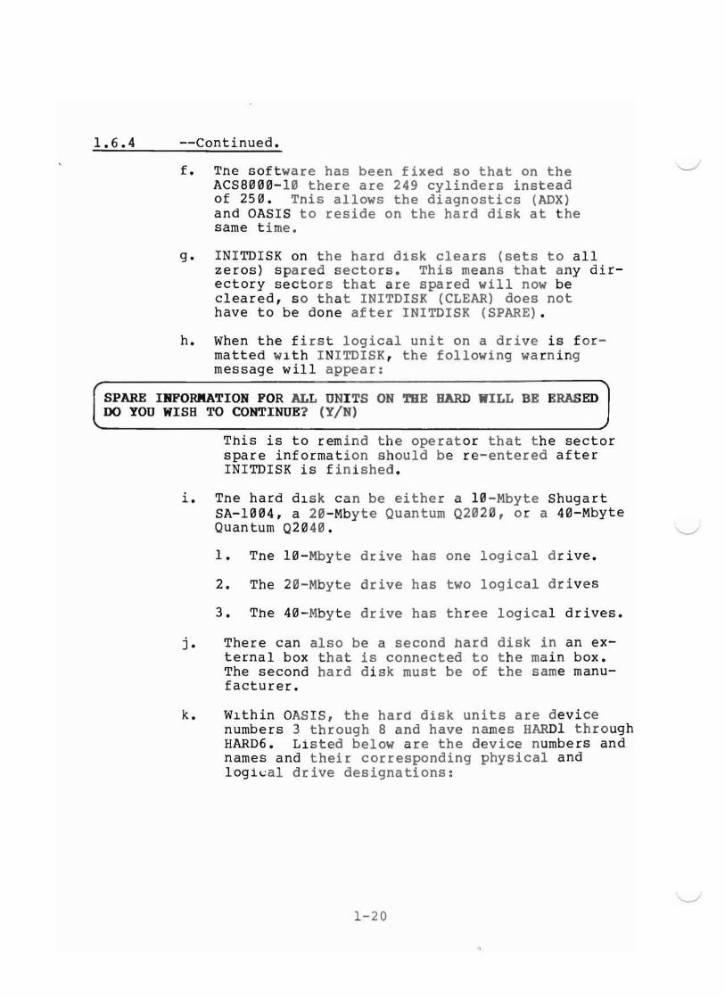
h. When the first logical unit on a drive is formatted with INITDISK, the following warningmessage will appear:
~
SPARE IRFORKATION FOR ALL UNITS ON THE BARD WILL BE ERASEDDO YOU WISH TO CONTINUE? (YIN)
This is to remind the operator that the sectorspare information should be re-entered afterINITDISK is finished.
i. Tne hard dlSk can be either a 10-Mbyte ShugartSA-1004, a 20-Mbyte Quantum Q2020, or a 40-MbyteQuantum Q2040. '-/
1. Tne 10-Mbyte drive has one logical drive.
2. The 20-Mbyte drive has two logical drives
3. The 40-Mbyte drive has three logical drives.
j. There can also be a second hard disk in an external box that is connected to the main box.The second hard disk must be of the same manufacturer.
k. Wlthin OASIS, the hard disk units are devicenumbers 3 through 8 and have names HARDI throughHARD6. Listed below are the device numbers andnames and their corresponding physical andlogi~al drive designations:
"-.-/
1-20

1.6.4 --Continued.
Device Device Logical PhysicalNumber Name Drive Drive
3 HARDl First First4 HARD 2 Second First5 HARD3 Third First6 HARD4 First Second7 HARD5 Second Second8 HARD6 Third Second
The following table shows the disk drives capacities and directory sizes for the logical driveson the various drive sizes. The units are designated S, A and B.
Unlt Desig- Capacity Default Starting Ending Number Numbernation Mbytes dir size cyl no. cyl no. of cyl of heads
10 Mbyte S 8.7 1968 1 249 249 420 Mbyte S 16.7 1936 1 480 480 4
A .9 880 481 505 25 440 l-1byt S 16.7 1936 1 240 240 8
A 16.7 1936 241 480 240 8B 2.0 1992 481 508 28 8
Some of the restrictions of the OASIS operating system arelisted below:
a. OASIS boots from only the first logical uniton the first hard disk. That unit is the onlyhard disk unit that can be used as the systemdisk.
b. Tne locations of the logical units on the harddisk is fixed. The locations cannot be movedto other places on the hard disk by the user.
c. BOOTWRIT can only be run on "large" systemdlQks sUCh as the 16.7 Mbyte logical drive onthe ACS8000-l2 and ACS8000-l4.
d. Tne SYSTEM. NUCLEUS is about 500 bytes largerthe previous version.
1-21

1.6.4 --Continued.
Tne directory s~ze can be specified to some othervalue by using the SIZE option on INITDISK. The default valuelisted aoove is also the maximum value allowed. None of theother values listed above can be changed.
SYSTEM DISKETTE NUMBER 2
The Oasis operating system has become too large to fit on onedouble density diskette. Thus, two diskettes are now required.Tne first d~skette contains the SYSTEM.NUCLEUS file and allutility commands. The second diskette contains all 29 of theterminal class files (previously only 9 class files were on thesystem disk) plus some other miscellaneous files that aredescribed below.
The terminal class files are names SYSTEM.CLASSn where n is anumber from 1 through 33 that represents the class code. Seethe next page for a descr iption of the terminals supported by theclass codes. (note: Class codes 16 through 19 are not currentlyuseu. )
The other files on the second system diskette are the following:
ASM.EXEC- EXEC program that performs assembly and link
CLASS.MACLio - Macros that are needed to create additionalterminal class files.
BOOTWRIT.COMMAND -command to create a boot tape
ACSTPLDR.ABSOLUTE - Tape loader program. BOOTWRIT copies thisfile to the boot tape as the first block.
SYSTEM.EXEC2 - EXEC scratch file for partition 2.
SY~TEM.EX~C3 - EX~C scratch file for partition 3.
SYSTEM.EXEC4 - EXEC scratch file for partition 4.
SY~TEM.HARDBOOT - Boot program for 14" hard disk. This programonly applies to the -6 and -7 systems. It canbe copied to a blank diskette, and then whenthat diskette is booted from, the system willbe loaded from the 14" hard disk.
1-22
J

1.6.5 Code Terminal.
1 Beehive Bl~~
2 ADDS 58~ Envoy3 Lear Siegler ADM 3A4 Soroq IQ l2~
5 Special (VDM)6 Hazeitine l5~~
7 Televideo TVI9l2/92~
8 Perkin Elmer FOx9 Perkin Elmer BANTOMl~ Heath H19 (ANSI)11 Infoton l~~
12 Vector Graphic Flashwriter (VDM)13 Tandy Radio Shack TRS8~ II (VDM)14 Elbitt15 ADDS Regent 2~
161718192~ Intormer 3~4
21 Data Media22 IBM 3l~1 (Uses ESC,ESC for system control)23 S D Systems VDB 8~24 (VDM)24 Intertube25 Volker-Craig VC4~4
26 Teleray l~~~ Series27 Tektronix 4~
28 V1sual 2~~
29 Heath H19 (Heath Mode)3~ Zentec Zepher31 Televedeo TV195~ (Uses ESC,ESC for system control)32 Hazeltine Modular One33 Kontron P~I8~ (VDM)
1-23

The INITDISK command allows you to initialize a disk for use byOASIS. This description only covers the initializing of the harddlok on ACS8~~0-l0, -12, and -14 systems. For other informationabout INITDISK, see the OASIS Reference Manual.
1.6.6 INITDISK Command.
~
INITDISK should be executed several times in order to correctlyinitialize the hard disk. The first INITDISK will perform theformat operation and the second will allow the entering of spareinformation.
Then, if the hard dlsk has more than one logical unit (i.e., ifthe system is a -12 or a -14), INITDISK should be executed oncefor each of those units to perform the format operation.
Formatting the first logical unit on the hard disk will erasespare information for all units on the drive. The followingwarning will be displayed to remind the operator of this:
SPARE INFuRMATION FOR ALL UNITS ON THE DISK WILL BE ERASEDDo you wish to continue? (YIN)
INITDISK will aoort if N is entered.
The important thing to remember about formatting the hard disk isthat the TRACK and HEAD options must be specified so thatINITDISK knows how big the hard disk drive is. These optionsspeclfy the total capacity of the physical hard disk drive - notthe size of the one logical unit that is being initialized. ThefOllowing table shows the only three acceptable combinations ofTRACK and HEAD options:
SYSTEM TRACK HEAD
8000-10 (10Mbytes) 256 480~0-12 (20Mbytes) 512 48000-14 (40Mbytes) 512 8
If any other combination of values is specified, then INITDISKuses the default values of 256 for TRACK and 4 for HEAD (i.e. thedetault is a l~ Mbyte drive).
NOTE: The format operation on a hard disk unit is somewhat timeconsuming. For the single unit on a -l~, it takes about 15minutes. For the large 16.7 Megaoyte units on the -12 and -14,it takes about 25 minutes.
1-24 ~

1.6.6 --continued.
In some rare instances, it might be desirable to pretend that a40 MByte disk is only a 20 MByte disk. that is, only half of thehard d1sk (i.e. heads 0, 1, 2, and 3) would be used; the otherhalf (i.e. heard 4,5,6, and 7) would be "wasted" (or used forsome other purpose besides an OASIS disk). This can be doneby simply "lying" to INITDISK about the size of the disk withthe following command:
INITDISK A (FOR}1AT TRACK 512 HEAD 4)
After running INITDISK, boot the system before entering anyspares. Wnen the spare information is entered, skip thoseentries on tne media defect report that have heads 4, 5, 6, or 7.But, to reiterate, this is not the normal situation. You shouldhave a very good reason for wanting to do this.
The cylinder numbers that are displayed by INITDISK as it isformatting a disk are real cylinder numbers on the hard disk(i.e. numoers from 0 through 255 or 511 depending upon the disksize). In previous versions of INITDISK, these numbers were offby one since cylinder 0 is not used. But beware that othercommands (such as VERIFY) display logical cylinder numbers (i.e.numbers starting at 0 for the first cylinder number on thelogical unit.)
1-25
The INITDISK command provides sector sparing either automatically or on command. Whenever the hard disk is formatted,the I~ITDISK program checks for any bad sectors (sectors thatcannnot be written or read reliably). When a bad sector isfound, it is spared to the first physical track on the disk.(This track is guaranteed by the disk manufacturer to be errorfree for the life ot the disk drive.)
1.6.7 Sector Sparing.
o
Alternately, spare sectoring may be done by specifying thespecific sector that is to be spared. This mode is invokedby executing the INITDISK command with option SPARE specified.
When using this method of sector sparing for a new d~sk
drive, you should have the media defect report from Shugartor Quantum available. This report is a form that the diskmanufacturer uses to inform you of the sectors that it hasfound to be questionable. This report is sealed in anenvelope on the inside of the bottom cover of the machine.When you are installing the machine, you have to remove thiscover to disable the locking bracket on the hard disk; atthis time, you shoula make a copy of the media defect reportso that it will be available when you run INITDISK with theSPARE option.
If you want to enter sector numbers (as shown in OASIS errormessages), enter S. If you want to enter bit/byte informationfrom the Shugart or Quantum Media Report, enter B. Whenyou have entered the last entry. type a RETURN only inresponse to the track numb~r prompt.
(Note: If you are using a Quantum Media Defect Report,be sure to enter only the decimal numbers - not thehexadecimal numbers. The decimal numbers are thoselisted to the left of the "/" in each field.)
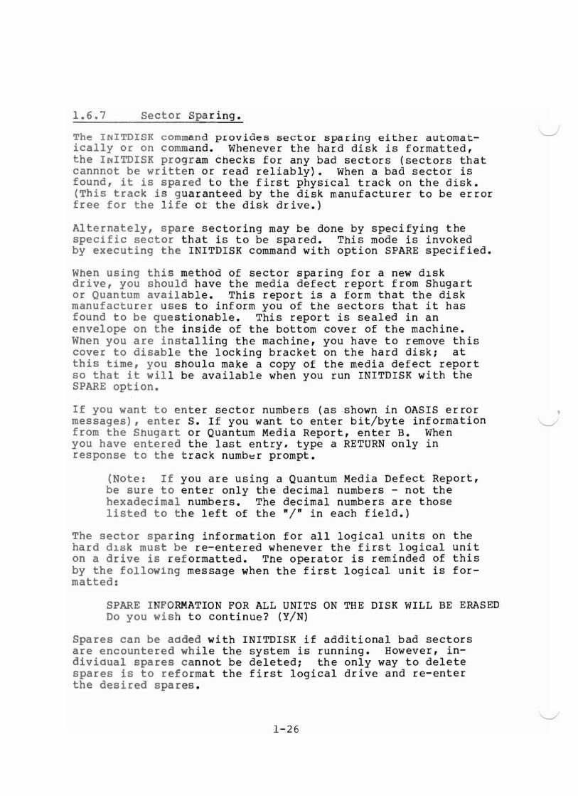
The sector sparing information for all logical units on thehard d1sk must be re-entered whenever the first logical uniton a drive is reformatted. The operator is reminded of thisby the following message when the first logical unit is formatted:
SPARE INFORMATION FOR ALL UNITS ON THE DISK WILL BE ERASEDDo you wish to continue? (Y/N)
Spares can be aaded with INITDISK if additional bad sectorsare encountered while the system is running. However, indiviaual spares cannot be deleted; the only way to deletespares is to reformat the first logical drive and re-enterthe desired spares.
1-26
\....J
-.....J

1.6.7 --Continued.
If it is anticipated that the spare information will haveto be entered fairly frequently (as might be the case on thetest floor), the spare information can be included in anEXEC program. However, EXEC thinks that lines that beginwith a number have line numbers on them. So, when creatingthe EXEC program either put line numbers on the statements orput some leading blanks on line that have numbers on them.The following EXEC program will enter the spares for themedia defect report shown in Figure 1-2.
&BEGSTACKB
66e227911
79115491
93661991
&ENDINITDISK A (SPARE TRACK 512 HEAD 8)
1-27

1.6.8 BOOTWRIT Command.
The BUOTWRIT command provides a means of writing boot tapes.Boot tapes can be used on -10, -12, -14 MTU systems to initialize the hard disk and to copy the operating system fromthe tape to the hard disk.
The format of the command is:
BOOTWRIT [<fdl> [<TAPEn>JJ
where
'-/
fdl
TAPEn
indicates the disk drive containing the systemto be copied. Default is S.
indicates the tape drive containing the tape tobe copied to. Default is TAPEI.
BOOTWRIT expects the file named ACSTPLDR.ABSOLUTE to be onthe source disk. It copies that file to the tape as thefirst block, and then copies all of the files on the diskto the tape. The resulting tape is called a boot tape.Boot tapes are not compatible with either backup tapes orwith archive tapes; they can only be used for booting thesystem.
Run BUOTWRIT as follows:
a. Attach the tape with the following command
>ATTACH TAPEI TAPEDRV
b. Tension the tape with the following command
>INITTAPE (TENSION)
(Note: Boot tapes do not have to be labeled.)
c. Ensure the source disk contains ACSTPLDR.ABSOLUTE.
d. Perform the command:
>BOOTWRIT STAPEl
e. Insert a blank tape when asked to do so.
f. When BOOTWRIT has finished, remove the tape.
g. WRITE PROTECT THE TAPE IMMEDIATELYl
1-28
o

1.6.8 --Continued..
The boot tape should be tested immediately to see if anyerrors occurred when the tape was written. The followingprocedure can be used to test the tape without overwritingthe data on the hard disk: .
a. Push the reset button and interrupt boot by pressingany key.
b. Enter 3 to boot from tape.
c. If the format question appears on the screen, theboot tape is okay since the first tape block has beenread correctly.
d. Push the reset button to boot up the system again.
e. If the format question does not appear on thescreen, then the boot tape was not written correctly.Push the reset button to boot up the system again,rerun BOOTWRIT, and test the boot tape again.If it fails again, try··another tape.
The fOllowing procedure can be used to boot from tape to loadOASIS to the hard disk:
a. Insert the boot tape.
b. Push the reset button and interrupt the boot bypressing any key.
c. Enter 3 to boot from tape.
d. Answer Y to the format question if you wishto format the hard disk. Then enter thenumber of cylinders (either 256 or 512) andthe numb~r of heads (either 4 or 8) for thehard disk.
e. Answer Y to the spare question if you wish toenter any spare information. If you want toenter any sector numbers (as shown in OASISerror messages), enter S. If you want to enterbit/byte information from the Shugart orQuantum Media Defect Report, enter B. Whenyou have entered the last entry, type a RETURNonly in response to the track number prompt.
Note: If you are using a Quantum Media DefectReport, be sure to enter only the decimal numbers.
1-29

1.6.8 --Continued.
f. Press any key to start the copy from tape to thehard disk. DO NOT REMOVE THE BOOT TAPE UNTIL THECOPY OPERATON IS FINISHED.
g. Press the reset button to boot from the hard disk.
BOOTWRIT is not intended to replace BACKUP. Use BOOTWRITto make a copy of the boot tape that is delivered with yoursystem; that is, BOOTWRIT should be run as soon as the systemis installed. Use BACKUP periodically to insure that youhave an up-to-date copy of your hard disk data.
BOOTWRIT cannot create multi-volume tapes.
In mu~~i-user OASIS, BOOTWRIT must be run in single usermode.
A FINE POINT:
Currently, BOOTWRIT must be run on a disk unit that hasthe maximum size allocation bit map. The 16.7 Mbyte unitson the -12 and -14 are such units. Also, the system diskcreated by booting from tape is such a unit.
1-30
-....J
•'-..-/
~

1.7
1.7.1.
system Configuration.
Hardware Configuration Jumper Block.
If your distributor has not configured your system foryou it will be necessary to remove the top cover and set thesystem configuration jumpers. This is done on the 8500 CentralProcessing Unit Printed Circuit Board (CPU PCB) as shown in Figure 1-6. Figure 1-7 shows the system hardware configurationjumper options.
1.7.2. software Configuration Jumper Block.
It may also be necessary to configure your systemto conform with the operating system software (CP/M, MP/M orOASIS) you are using. Figure 1-7 shows the system softwareconfiguration options.
1.7.3. MUl~i-user/NetworkingPort Configuration Jumper Block.
The Multi-user/Networking Port, located at matrixposition l6C/D, enables Consoles #2, #3 and #4 and Printer #2.Figure 1-8 shows the proper jumper configuration.
Eignt-inch Hard Disk Controller.
Figure l-l~ is a matrix map of the eight-inch hard diskcontroller and the S2 Configuration for Quantum or Shugart Drivesis highlighted.
1-31

HARDWARE CONFIGURATIONMATRIX POSITION 2lP
C:=====:JI J~ JZ
QrJ 0'1'
,..ill;]OU1D
="S
oo 0u,',
OnDo~~
@1~·~Aj
SJ~
1[;]~"O'l'1'l'.=.10 w;
,11< CJeti~ O,~r~
.P.a:::=::::J .:. S.
~.\J~~ ~ ~O[~:;J ~
0"·' t:=).~ It.~
I1J
O·bR:J :>O~~
...=-
8D @:]'~~0,1.~~= ...~;U~~.
Q.
I~ ~'(I)~. '" <' q;;;;e' '" <u '0lolA c:::> CJ S'M. c:;::;r,ll' a::=::::::::J (lie 8~\\ t".. ~lt 'OQ~ UliJ,·f,,,·1 ~ ~, (\I ~(tJ l~" LiliJ il'~ll:.o:!U.Y,OJ~.'...O~'J" n; tAt Q <==)1" rHe,,- L~ c=> a'lI. I I .~ '1\
, u' ,~no ,~~,O\~l~W;2.~1 ~8"[iT<JO .. iJ:ill.g' ~ 'J,'.~~ [ffiJ,' ~tQl [iEJ~.
~~~~lliDJ~~U~ ~ ,,·0:'~!1lU~~~~1
'I <:J. III "I. (I., CJ -u (1;..:.'__---,
,; f 204 I f we I f <DE 20" I ~ f '0" i
f 11E I~~~~b;'!~~~ Ulo< .g 5 ,-.a
GD G£Jj()~ = ~C~=~~~.:=:::J ~ J5 i I I ~J.s
EJ .10~ 5Ji!li ~~~ GIJL[jj~ 14;=Sli., J~'~Ill.'.,"I ,.to ,"',Jl ~ ~"'O.g.., C> ... Iii' ~ ~ 9.. 'iT.
1'\' <::J c=l-ll:'. c=>-_u
~ ~ Gill~ O'M
to~' ~ G.liJ '" GQ]l6C/ol =".. I) '"G!D ~~ =
ll:~cc=::=J ~
:OGQD ~ G2fJ
SOFTWARECONFIGURATION(MATRIXPOSITION
CONSOLE #2ENABLECONFIGURATIONMATRIXPOSITION
~lDo:LJlD; 8ZJ!] JQDlJ'=!UID~IDCEJID~1D8JOO~ID ,JQD:lJ\iflOO~OO~1]
GDOO~rnw:J1D OGQ]tlJ~lD~lD~lJ
o.uoo~oo~rn U~OO~OO~ID~lD
GDOO~W~aJ U~W~[[]~OO~ID
~1D~iD~W ll~I]~OOC3QIIJCEJrn
QTIOOCilllDCl£JilJ ,J~lll ClUaJ~1D~2!DaJI GTIrn~lD\ Ie JW UG:Q]JJ~ " JQ]I IF IOJ~m
--- Start Address 0000 4000End Address 3FFF 7FFF
OOZJOO ODDULJID O[EJOO~OOGD0OGLJOO~OJG:Jrn O~ID5:JlJJ~O
JGZJlDG..;J(lJ\ ,,"cOO ocaOOG:;:JWLLJO08D]Q;]lDGQID U~IDu;:JOODDO
JGLJIDO;]lU~LDU~Q]\ AN 'aJGDOJDLlaJD:;JlDULJOO QQ;]lD~UO~U
,1\ i.:OW~OOUhJl) JO:;]\lJu::;::JID~O
It :2.J1D~mC!h:JJJ JI 'M ILlJ~lIJ~
8000 C000BFFF F8FF
'-.-/
Figure 1-6. 8500 PCB Matrix Map Highlighting Hardware, Software and Mul~i-User Configuration Block options
1-32
I
~

7 it 5 4 3 2 o
0000000000000000
r HARD DISK FAMILY"'"---8 11
'-- FUTURE USEFUTURE USE_~
NUMBER OF--- HARD DISKS
SINGLE OR DOUBLESIDED FLOPPY DRIVE
PIN NIDmER
0,1,2
3
r1EA~nNG
Designates Hard Disk Family:210o 0 ol Not Jumpered for SAlaaO Family~ (8" Hard Disk)~ Jumpered for SA 4000 Family~ (14" Hard Disk)
Reserved--Must Not be Jumpered
of Hard Disk Drives;
Jumpered for two (2)
4 ~o~eSignate~ numbedr
QJ Not J umpere
]}for one (1) Hard Disk
Hard Disks
5
6,7
Figure 1-7.
Designates Number of Sides on FloppyDisk Drive(s)
~ Not Jumpered fer Single-sided Drive(s)
JO Jumpered for Double Sided Drive(s)
Reserved--Must Not be Jumpered
8500 CPU PCB Sl Hardware Configuration BlockOption (Matrix position 2lP)
1-33

[rn
~
CP/M & MP/M Software Configuration
OASIS Software Configuration
'---./
Figure 1-8. Software ConfigurationMatrix (Position 12A/B)
8S00CPU-L008"-.../
13 15 17 19
oo
3
Q5
oo
7 9
11
oo Q
oo Q
oo
2 4 6 8 10 12 14 16 18 20
8S1111CPU-L009
Figure 1-9. S13 MU1~i-user/Networking Port Configuration Jumper Block (Matrix Position16C/D)
1-34
I
J

) ) )
Frontal View of PCB
00
II
Quantuml II00
...")
o::JCJ=cw;; ~
~~cl;QC~ U
~ il I o::::J IT]~c:=> ~c=' ~CJ'" _. ..:I
~~~CJ----,
I ci: J.. I _ I I N II I
Q;< S? ~ [I] ~ ., ~ ~O ~:> [L] CI:J i(J CD ..CD IT] [TI~:c=» c:::l'l. ;tCJ- .i,==, V~c:::::)
Et::J.orn~ [TIv CD dJ CD:: ~~
[I::] IT] CD CD ~ a::J ~c::::::> \J .C'l ~,- .... ~.N..-=« ... ~ •
E !i3@"N ~ i~?:O =~ :;;; ~.sIT::] ~ ~ I o::J [L] ITJr O~ylt~
:3= CJ~ "fs ",' s=~= ~ ff-.~IT:] ~ ~ I ;;: [D o:::::J ~O:b ~~= ~ ...nfh'! P ~
1 ~ I ~ ~ I CD "lJ..'Wii IT:] CD ~Q:=u 9 ,__ .. v
>~ lo::J ~g I >~~ J CO"
I-'IwU1
8se"BDC-LIJIJ6
Figure 1-10. Eight-inch Hard Disk Controller BoardHignlighting the S2 (Matrix Position 3/4G)Sector Size configuration.
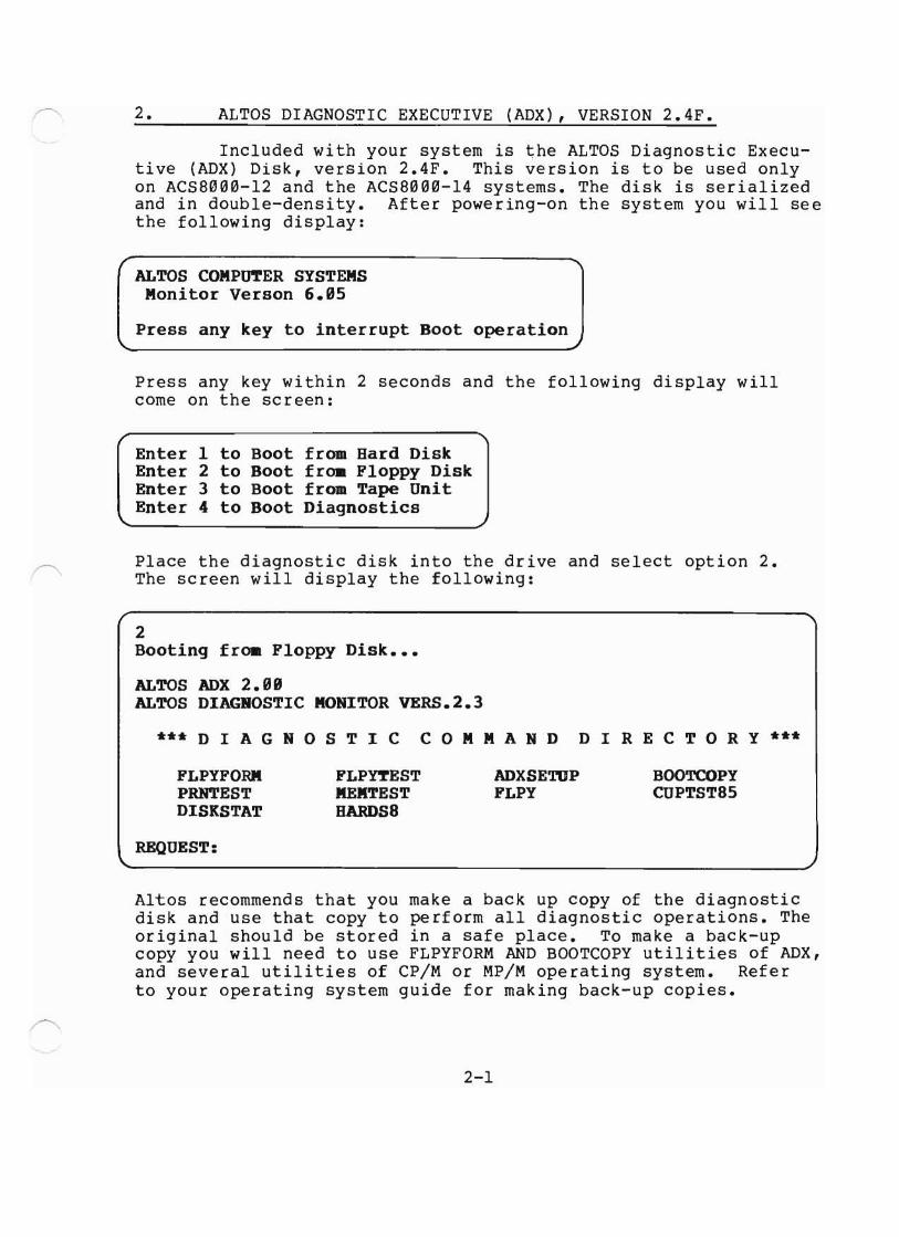
2. ALTOS DIAGNOSTIC EXECUTIVE (ADX) , VERSION 2.4F.
Included with your system is the ALTOS Diagnostic Executive (ADX) Disk, version 2.4F. This version is to be used onlyon ACS8000-12 and the ACS8000-14 systems. The disk is serializedand in double-density. After powering-on the system you will seethe following display:
Press any key within 2 seconds and the following display willcome on the screen:
Enter 1 to Boot from Hard DiskEnter 2 to Boot from Floppy DiskEnter 3 to Boot from Tape UnitEnter 4 to Boot Diagnostics
Place the diagnostic disk into the drive and select option 2.The screen will display the following:
2Booting from Floppy Disk •••
ALTOS ADX 2.99ALTOS DIAGROSTIC MONITOR VERS.2.3
*** D I A G NOS TIC COM MAN D D IRE C TOR Y ***
FLPYFORMPRNTESTDISKSTAT
REQUEST:
FLPftESTMEMTESTDAROSa
ADXSETDPFLPY
BOOTCOPYCUPTST85
Altos recommends that you make a back up copy of the diagnosticdisk and use that copy to perform all diagnostic operations. Theoriginal should be stored in a safe place. To make a back-upcopy you will need to use FLPYFORM AND BOOTCOPY utilities of ADX,and several utilities of CP/M or MP/M operating system. Referto your operating system guide for making back-up copies.
2-1

2.1 Diagnostic Command Categories. vThe utilities and tests of the command directory can be
broken down into three categories and are described in subsequentsubsections. The prompts that will be displayed and the requiredresponses are also given. The three categories are given below:
2.1.1
a. SETUP/FORMAT/COPY UTILITIESb. COMPUTER AND FLOPPY DRIVE TESTSc. HARD DISK FUNCTIONS/TESTS
SETUPLFORMAT/COPY UTILITIES.
The utilities given below are designed for your Computer System.
ADXSETUP FLPYFORM BOOTCOPY FLPY
The above utili ties are most widely used by· the end-user.
2-2
'-..J
"'-/

2.2 ADXSETUP utility.
This utility is used to specify baud rates fOr theconsole, printer and auxiliary port. You should specify the default density for the floppy drives. After the screen displaysthe command menu, select ADXSETUP as follows:
REQUEST: ADXSETUP <CR>
The screen will display the following:
8 DON'T CHARGE CONSOLE BAUD RATE1 110 BAUD2 308 BAUD3 600 BAUD4 1288 BAUD5 2400 BAUD6 4888 BAUD7 9608 BAUD
Select the baud rate applicable to your terminal bythe list item number. The ALTOS system requires that terminal#1 have a 9600 baud rate. After you have made your selectionpress return. You will be prompted for the baud rates forconsoles #2 and then #3 and #4 together.
The next display will prompt you to select the baudrate for the printer as follows:
SELECT PRINTER BAUD RATE FROM FOLLOWING LIST
8 CENTRONICS PRIBTER (PARALLEL PORT)1 118 BAUD2 300 BAUD3 688 BAUD4 1208 BAUD5 2488 BAUD6 4888 BAUD7 9688 BAUD
2-3

2.2 --Continued.
Select the applicable baud ~ate for the printer youare using with your system by list item number. Please notethat if you are using a Centronics printer which is operatingas a parallel device as opposed to a serial connected printer,then you will select 0. If, however, you are using a Centronics printer that is serially connected, select the applicablebaud rate. You may have to consult the user's manual for theprinter to determine this specification. Make your selectionand press return.
The next display is to determine the baud rate forthe auxiliary port. Since this port is not presently used,select 0 and press return.
You will then determine the default density mode forthe floppy disk drives. The display will be as follows:
SELECT DEFAULT MODE FOR FLOPPY DISKS," (SINGLE)1 (BLOCKED DOUBLE DENSITY)2 (URBLOCKED DOUBLE DENSITY)
Normally you would select Option 1 (Blocked bouble density) sinceit allows more storage space. Make note of the option you doselect as you will want to thereafter format all your disks inthat density. If you wish to change the disk drive density modeyou will have to run ADXSETUP again.
Blocked double density means that the default mode ofthe disk is 512 byte sectors. The operating system will setthe computer hardware to initialize to the default density depending on this selection. This selection effects the diagnosticdisk on boot and any other disk you might insert while performinga diagnostic operation and it does affect all floppy disk drives.MaKe your selection and press return. If you make an error andselect any number other than 0, 1 or 2 you will receive anerror message and be asked to select again.
The next display will be for determining whether youhave a single- or double- sided floppy disk:
SELECT SINGLE OR DOUBLE BEADED DISKS, 1 (SINGLE), 2 (DOUBLE)
Select option 1. The screen will display the following:
2-4
...J
"-../
"-../

2.2 --Continued.
PLACE DISK WITH BOOT TO BE UPDATED IB EITHER DRIVE A:OR DRIVE B: REMOVE DIAGNOSTIC DISK IF NECESSARY.REPLY WIm DRIVE LETTER (-A- OR -B -) WHEN READY TOPROCEED.
If you are updating the diagnostic disk you are presently using then enter the letter A and press return. If youhave another copy of the diagnostic disk and wish to update thatdisk, remove the diagnostic disk presently in use and place thedisk to be updated in the drive and press return. The screen willdisplay the following:
If the diagnostic disk you updated is not the diagnosticdisk you are using, then place that diagnostic disk in drive Aand press return.
2-5

2.3 FLPYFORM utility.
This command allows the user to (1) format floppydisks before first time use, or (2) reformat a disk that hasbeen previously formatted. Note that anytime you format afloppy disk you erase all data on that disk. You will be ableto format floppy disks for either single, blocked (512 bytesectors) double-density or unblocked (128 byte sectors) doubledensity and perform formatting on any logical drive, A, B, Cor D. You must refer to your ADXSETUP routine and the densitymode you established for the floppy drive when formatting ablank diskette. Be extremely careful that you do not accidentally format the diagnostic disk. To execute FLPYFORMfollow the procedure below.
Insert the diagnostic disk in the drive. Press thereset button on the front panel. Select FLPYFORM as follows:
'-'"
REQUEST: FLPYFORM <CR>
The screen will display the following:
......•••• ALTOS FLOPPY DISK FORMAT ROUTIBE •••VERSION 2.99
1. STARDARD SIRGLE DENSITY FORMAT2. DOUBLE DENSITY FORMAT FOR CP/M AND DIAGNOSTIC DISKS3. DOUBLE DENSITY FORMAT FOR MP/M4. DOUBLE DENSITY WIm 512 BYTE SECTORS FOR CP/M AND MP/M5. END THIS PROGRAM
SELECT FORMAT OPTION BY NUMBER
Again you must know the drive density you selected duringADXSETUP and select appropriate option by list item number;press return. The screen will display the following:
PLACE DISK TO BE FORMATTED IN AVAILABLE DRIVEREMOVE DIAGROSTIC DISK IFRECESSARY.WHEN READY TO PROCEED,REPLY WITH DRIVE LETTER:
Insert the blank disk into the drive; close the loading door,enter the drive designation on the terminal and press return.Your disk is now being formatted. When the task is complete,the screen will display the following:
2-6

2.3 --Continued.
DISK IN < > HAS BEEN SUCCESSFULLY FORMATTED
•••• ALTOS FLOPPY DISK FORMAT ROUTINE ••••VERSION 1.18
1. STANDARD SIRGLE DENSITY FORMAT2. DOUBLE DENSITY FORMAT FOR CP/M AND DIAGNOSTIC DISKS3. DOUBLE DENSITY FORMAT FOR MP/M4. DOUBLE DENSITY FORMAT WITH 512 BYTE SECTORS FOR CP/M AND MP/M5. END THIS PROGRAM
I
SELECT FORMAT OPTION BY NUMBER
To end this program select option 5 and press return. The nextprompt will take you back to the diagnostic menu:
2-7

2.4 BOOTCOPY utility--One Floppy Disk Drive.
The BUOTCOPY utility is designed for systems thathave only one floppy disk drive. However, this utility willwork just as well on systems with two or more floppy diskdrives. It allows you to copy the operating system tracks,o and 1, from a source disk such as the operating system disk,to any object disk that has been properly formatted. The objectdisk should be in the same density as the source disk. If youhave one floppy disk drive and one or more hard disk drives,fOllow the procedure below.
Format a blank disk using the FLPYFORM utility discussed in subsection 2.3. This will now be the object disk.To perform the BOOTCOPY operation you will need the diagnosticdisk, a source disk and the object disk.
Insert the diagnostic disk into drive A. Select BOOTCOPYas follows:
"----'
REQUEST: BOOTCOPY <CR>
The screen will display the following:
BOOTCOPY version 2.10
SOURCE ON A:TYPE <CR>
When this prompt is given, remove the diagnostic disk and placethe source disk in the drive; Press return. You will then beprompted to remove the source disk from drive A and insert theobject disk as follows:
'-....J
OBJECT ON A:TYPE <CR>
BOOTCOPY COMPLETEINSERT DIAGNOSTIC DISK
<CR>
NOTE: At this point the object disk contains the operatingsystem on tracks 0 and 1. It does not contain data tracks. Ifyou wish to transfer data from the system disk onto the objectdisk, follow the PIP procedure outlined in the ALTOS ComputerSystems current version of CP/M, or the ALTOS Computer Systemscurrent version of MP/M copy or transfer data from the sourcedick to the object disks.
2-8
'J

2.5 FLPY utility.
This utility allows the user to perform the functionslisted in the submenu below. Since this utility requires thatyou have at least two floppy disk drives on your system, it doesnot apply to the ACS8991-l2 or ACS8999-l4 Computer unless youhave aaded more floppy drives. It also requires that you copylike disks to like disks. If you have a double-density sourcedisk, your object disk must also be double-density. To performthis utility format the object disk using the FLPYFORM utilityor list item 0 on the submenu below. Then return to thediagnostic menu. After selecting FLPY, you will see the followingscreen display:
•••• ALTOS FLOPPY DISK COPY ROOTIRE ••••VERSION 2.1
Select one of the following options:
I. Format disk only (Formats floppy disk)
1. Copy system tracks (Copies system tracksonto formatted disk)
2. Copy SIRGLE density disk (Copies entire disksin single density whenobject disk is formatted in single density)
3. Copy SINGLE density disk data only (Copies data only ontosingle density disks)
4. Copy DOUBLE density disk data only (Copies data fromdouble density disksto formatted doubledensity disks)
5. Copy DOUBLE density disk (Copies entiredouble density diskonto a formatteddouble density disk)
6. Copy BLOCKED DOUBLE density disk (Copies 512 byte sectored double densitydisks)
7. Copy BLOCKED DOUBLE density disk data only(Copies data from512 byte sectoreddouble density disks)
8. End this program
2-9

2.5 --Continued.
For single density disks the screen will display the following:
ALL TRACKS WILL BE COPIED
'---./
+SOURCE IN A+OBJECT IN B+TYPE <RETURN> <CR>
For double density disks the screen will display the following:
ALL TRACKS WILL BE COPIED
WHAT KIND OF DISK ARE YOU COPYING?
1. MP/M2. CP/M OR DIAGBOSTIC DISK3 • OTHER (OR DON' T KNOW)
+SOURCE IB A+OBJECT IN B
\.. +TYPE <RET> <CR>
Remove the diagnostic disk from drive Asource disk. Insert the object disk in drive B.If the source or object disk has errors or unlikefollowing display will appear:
and insert thePress return.densities the
"--./
PERMANENT DISK ERROR, DRIVE DD TRACK TT SECTOR SS STATUS 19PERMANENT SOURCE ERROR EXIT•••• FUNCTION FAILED••••
If there are no source or object disk errors the functionwill complete successfully and the screen will display thefOllowing:
+FUNCTION COMPLETE+REPLY WITH -R- TO REPEAT OR <RET> TO END:
<CR>
INSERT DIAGNOSTIC DISK IN A: TYPE <RET><CR>
~
2-10
"-./

2.5 --Continued.
Once the task is completed, it is a good idea to boot thenew diskette or to look at the directory of the new diskto ensure that you have copied the desired information.
2-11

2.6 SYSTEM AND FLOPPY DRIVE TESTS.
The following tests fall under this category:o
CPUTST85 FLPYTEST PRNTEST MEMTEST
The end-user should not have to use these testsunless there are problems with drives, printer, memory orthe CPU PCB. Consult with your distributor.
2.7 CPUTST85.
The following routines test various functions of the85BB CPU board and system. To enter a test routine type thenumber of the test after the praapt. If the test is coapletedwith no errors, a -NO ERRORS- message will appear and the testwill continue looping (for debugging purposes) until the ESCkey is pressed. Tests 4 and 5 do not print anything on thescreen. Test 4 requires that the user move the CRT terminalcable to the various serial connectors and see that keys pressedon the keyboard are echoed to the screen. Test 5 requires thata test fixture be connected to the network connector and a scopecheck of pins 12 and 13 of IC l7C be made. Both tests 4 and 5are terminated by pressing the ESC key.
B. Print this message.1. Test write protect function2. Test DNA chip and DNA banking.*3. Test memory banking.*4. Run and echo test for RS232 channel (hit ESC to return)5. Test Network channel (hit ESC to return)6. Test 95117. Return to operating system
Type the nuaber of the test (8-7)
* Tests 2 and 3 will not run if your system is pinned forOasis.
When test 6 is run, if the AMD9511 floating point processoroption is not installed, you will receive an ERROR DETECTEDmessage. To terminate this test press the ESC button.
2-12
\...J
\J

2.8 FLPYTEST utility.
This test allows the user to test all aspects ofoperation of the floppy disk drive. For the FLPYTEST todiscriminate between media problems with the floppy disk andhardware problems, the user should use a diskette that isknown to be free of errors.
After receiving the Diagnostic menu on the screen selectFLPYTEST as follows:
REOUEST:FLyYTEST <CR>
Have two scratch diskettes (formatted, data free) available forthis test. The following will appear on the screen:
Floppy disk test and stress analysis version 2.08
***HIT ESC. TO EXIT***
Load scratch diskettes in drive(s) to be testedHit <CR> when ready to proceed
ARE DISKETTES REALLY SCRATCH?? ·Y· OR ·S-:
Use diskettes with 128 byte sectors.-MODE 1- diskettes not supported.Enter ·S· for single Density, ·D- for double:
Will the terminal be connected during the test?Enter ·Y· or -N-:
If you select N, the terminal is disconnected andthe test will run continuously.
STARTIRG WRITE/READ DATA IBTEGRITY TESTS
••••••••WRITE PHASE
••DISK 8Trk: <Side:>
•• DISK 1Trk: <Side:>
•••••••• READ PHASE••DISK 8
Trk: <Side:>
••DISK 1Trk: <Side:>
(Disk 0 is in Drive A)
(Disk 1 is in Drive B)
2-13

2.8 --Continued.
Scratch diskettes should have the same default modes and shouldbe either single-sided or double-sided. Note that if you havedouble sided disk drives, you will see the side that is beingtested. Between the screen displays 'DISK 0 AND' DISK l'during the WRITE and READ operations there are pauses. Duringthis time tne system is writing to or reading from the disk.If terminal is disconntected, test will continually repeat.
Upon completion of the WRITE/READ operations. you willbe given the following prompts:
SWAP ALL DISKETTES, A: TO B:, B: TO A:, ETC. )THEN HIT <CR> WHEN READY
)
Af~er you have swapped diskettes a second READ Phase will occur;the disk that was written by drive A will be read by drive B;The disk that was written by drive B will be READ by drive A.This only occurs when the system has two floppy drives so thistest is not performed on systems having only one floppy diskdrive.
STARTING HEAD LOAD DELAY TESTS
HIT -ESC· TO EXIT<CR> TO REPEAT TEST
During this test the system rapidly selects and de-selects thefloppy disk drives for short periods. You will then see thedisplay:
DISK TEST COMPLETEDDTEST ERROR SUMMARY
TOTAL TRACKS PASSED n (number of tracks)
DRIVE S READ SSSS ( ), WRITE SSSS ( ), REF SBBS ( )DRIVE 1 READ SSSS ( ), WRITE SSBS ( ), REF SSSS ( )DRIVE 2 READ SSSS ( ), WRITE SSSS ( ), REF SSSS ( )DRIVE 3 READ SSSS ( ), WRITE SBSS ( ), REF SSBB ( )REPLACE SYSTEM DISK IN A:, BIT <CR> WHEN READY
The first 4 digltS will be in Hex and the second 4 digits willbe in decimal. The numbers given will be the number of errorsthat were found during the test. Even though the test madeseveral passes and picked up a given it will repeat that asanother error.
2-14
,---",'
'J
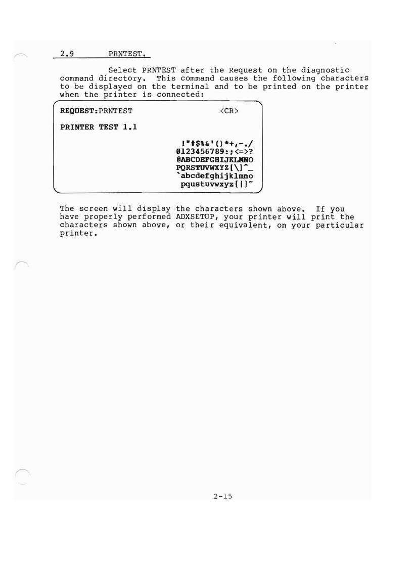
2.9 PRNTEST.
Select PRNTEST after the Request on the diagnosticcommand directory. This command causes the following charactersto be displayed on the terminal and to be printed on the printerwhen the printer is connected:
REQUEST:PRNTEST
PRINTER TEST 1.1
<CR>
1-'$%&' () *+,-.1B123456789:i<=>?@ABCDEFGBIJKLMROPQRSTUVWXYZ [\] ..._'abcdefghijklmnopqustuvwxyz{ I}-
The screen will display the characters shown above. If youhave properly performed ADXSETUP, your printer will print thecharacters shown above, or their equivalent, on your particularprinter.
2-15

2.10 MEMTEST.
MEMTEST command allows the user to test all but asmall portion of system RAM for possible errors. Since theprogram itself occupies some memory, that portion cannot betested. After inserting the Diagnostic Disk into drive Aand booting up the system, you will see the diagnostic menu.Select MEMTEST as follows:
REQUEST: MEMTEST <CR>
The screen will display the following:
"\ALTOS BOOT MEMORY TEST VERSION 1.1
VALID TEST MEMORY RANGE (HEX) BBBR - F8FF
SELECT MEMORY BARK TO BE TESTED)
You will be prompted 4 times to select memory bank. If youwish to select only one memory bank, Select bank, 0,1,2or 3, press return. Press return to bypass subsequent memorybank select option. You will now receive the following screendisplay:
STARTIRG ADDRESS (HEX)?ENDIRG ADDRESS (HEX)?
Rerer to Section 1, Figure 1-6, matrix map for memory addressselections. Memory test range is given in the screen displayabove. Select the starting and endlng addresses and pressreturn after each selection.
Memory testing will now begin. The screen will display .,;1 asit tests. These four characters indicate that one pass has beencomp~eted. You should allow the test to make eight passes.
If you wish to stop the test without terminating it, and seethe results, press (CTRL S) AS (STOP)on the keyboard and theresults will be displayed. If you wish to terminate the test,see the results and select another memory bank, press (CTRL R)AR (Restart) on the keyboard.
To go back to the diagnostic menu, press the RESET button on thecomputer.
2-16
~
-.....J
\,...,../

2.11 DISKSTAT.
DISKSTAT gives the status of each disk Enter DISKSTATafter the request prompt.
REQUEST:DISKSTAT <CR>
The screen will display the following:
DRIVE(S) A Floppy CylindersNo Temporary Errors
n Heads n SectorsNo Permanent Errors
DRIVE(S) B Floppy Cylinders n Heads n SectorsLast error Address: Cylinder I, Head I, Sector 1
The screen will continue to list the each drive and the status.If you wish to stop the test to read a portion of it withoutending the test press AS (Show); press any key to continuefrom that stoping point. The test will complete itself andautomatically return to the diagnostic command directory.
2-17

2.12 Hard Disk Tests and Functions.
The hard disk test used on the Computer system iscalled HARDS8. This test consists of twelve tests or functions.In order to run HARDS8 simply enter the command following:
REQUEST: HARDS8 (press return)
The screen will display the following:
*** Hard Disk (8-) Test Facility V3.4 ***Specify Configuration of HARD DISK to be tested.Default Configuration is:Drive Number : 1Cylinders per Drive: 256Number of Beads : 4Sector Size : 512press RETURN to bypass a selection.Enter Drive Number (-1- or -2-) <CR>
At this point you will specify the conditions underwhich you will run hard disk tests or functions. The followingprompts would appear as follows:
Enter Diagnostic Cylinder Number:
If you have the ACS80~0-l2 enter 506<CR>
If you have the ACS8000-l4 enter 509
Enter Diagnostic Bead Number 0 <CR>
Enter Number of Diagnostic Tracks 24 <CR>
Enter Operating System Type Number ~ <CR>
See Section 1.6 Operating Guide for default values for yourACS8~00-l2 or ACS80000-l4.
The screen will display the following:
2-18
'-...-/
'-..-/
\.J

2.12 --Continued.
*** Bard Disk (8-) Test Facility V3.4 ***1. Format Disk Drive2. Verify Addresses for all Sectors on Disk3. Seek test with optional Verify4. Write entire Disk5. Read entire Disk6. Set Flag Byte for a Specific Sector7. Bard Disk Read/Write Error Test8. Miscellaneous Functions9. Copy Diagnostics to Bard Disk19. Initialize Bard Disk System Track11. Copy System to Bard Disk12. Assign Diagnostic Area13. Terminate This Test Series
Select required function by number:
2.13 Hard Disk (8") Test Facility, V3.4.
In the following subsections each of facility andtest of HARDS8 will be discussed in detail. The tests thatare applicable to the ACS8000-10 are tests 1 thru 8. Tests9 thru 12 apply to non-floppy systems.
2-19

2.13.1 Format Disk Drive.
This function formats each sector on the hard diskdrive. This function will erase flag byte indications of badsectors (obtained from the Shugart Error Map provided witheach computer and all data. Sectors previously marked as badwill now be marked as valid. Unless these sectors are re-markedas bad sectors, data written on these bad sectors will be lost.
************************************ WARNING: This Bardtest function ** changes data on the hard disk ** and may cause loss of user data ************************************
Once you have selected test 1 and pressed return, the screenwill dlsplay the following:
*** DO NOT RUN THIS TEST WITHO~ PERMISSION FROM -AL~S- CUSTOMERSERVICE *** CALL 488-946-6799Do you want to continue?
If you wish to continue, enter Y and press return,you will return to the hard test selection menu. If you enterN and press return you will return to the hard test selectionmenu. The reason for this is that a "password" is requiredto run the hard disk format function. You can obtain this password from your distributor or from ALTOS Customer Service. Butbefore that password is given to you an attempt will be made todetermine whether a format of the hard disk is necessary. Sincethis function does destroy user data this safeguard was made apart of the function.
It you have obtained the password, entered that password and press return, the screen will display the following:
~
*** THIS TEST WILL ERASE FILES ON THE BARD DISK. ***Do you want to continue? (y or n):
.J
If you have determined that this is indeed the functionyou wish to perform, respond with Y and press return. The formatprocess will beg~n and you will see a count from ~ to 255appear on the screen as each cylinder is formatted. Oncecomp~ete the screen will return to the hard disk menu and youwill be prompted to make a selection.
REMEMBER: You have formatted the disk but you have not flaggedany bad sectors nor have you allocated dummy files to those badsectors. This should be done before any attempt is made totransfer user data to the hard disk. See Subsection 2.13.6.
2-20
'---./

2.13.2 Verify Addresses for all Sectors on Disk.
This is an address check. It is non-destructive touser data. This test will read every sector on the hard diskand cneck the first 3 bytes. These bytes contain the cylinder,head/ drive and sector numbers.
It you wish to run this test select 2 and press return.The screen will display the following:
Press any Key when ·ready· to Start this Test
Once any key is selected a return is automaticallygenerated and the test begins. You will see a count displayedat the bottom of the screen as the tracks are checked. Any badsectors encountered which have been flagged as being bad willcause a BAD SECTOR display. Any bad sectors encountered whichhave not been flagged earlier as bad will cause a CRC errordisplay. Once complete, the screen will display the hard disktest menu again with the following notation at the bottom:
C: ...Address Check Completed~
You will be prompted to select which hard disk test orfunction you wish to perform.
2-21

2.13.3 Seek Test with Optional Verify.
This test will seek between two operator specifiedcylinders and, at the operator's request. verify the addressesat heaa ~, sector ~ of each specified cylinder.
Select test 3 and press return. The screen will display:r ,Press any Key when -ready· to Start this Test
Press any key, return is automatically generated andthe screen will display:
(Enter ·seek· First Cylinder Number:)
Refer back to the beginning portion of HARDS8 whereyou specified how many cylinders you had on your system. You aregOlng to do a seek operation between two of those cylinders.You can seek between cylinder ~ and cylinder 255 at theex~reme, or cylinder ~ and cylinder 1 at minimum.
Select first cylinder number, press return, selectending cylinder number and press return again. The screen willdisplay the following:
Do you want test Verification of the Cylinder Ruabers? (y or n)
To the operator it doesn't appear to make any difference whether y or n is selected, the cylinder numbers will bedisplayed as the seek is performed, but if y is selected thelogic of the system reads data for each cylinder. With Verification selected a BAD SECTOR display will be generated if anybaa sector that has been flagged is encountered. If the head~ and sector ~ address of the specified cylinder has notbeen previously flagged as a bad sector, and the I.D. block forthat sector is bad, a RECORD NOT FOUND display will be generatedThe system may not performing the seek operation properly. Toverify that SEEK is performing properly, select another cylinder.
2-22
'-../
"-"

2.13.4 write Entire Disk.
This function will write a two-byte character to thedata block for each track of the disk. This character can beselected by the operator.
************************************ WARRING: This hardtest function ** changes data on the hard disk ** and may cause loss of user data ************************************
To perform the write test select test 4 and press return. The warning that this test will destroy files on the harddisk will appear and you will be asked if you wish to continue.If you do, enter y and press return. You will now be asked if youwish to write a specific pattern. If you have a specific patternwhich you prefer to use then enter y and press return. You will be.prompted to select the pattern you wish to use. If you have nospecific patte~n enter n and press return. The system will thenwrite its own character, E5H, on the disk. You will see the count,track by track, as it writes to the disk.
There are 4 different situations that could occur andthe error display will vary depending on which situation doesoccur:
a. Attempting to write to a sector which has beenflagged earlier as being bad will cause a BADSECTOR display.
b. While attempting to write to a sector which hasnot been flagged earlier as being bad, a sectoris encountered in which the ID Block CRC Bytesare bad. This will cause a CRC error display.
c. While attempting to write to a sector which hasnot been flagged earlier as being bad, but theI.D. block is bad. A RECORD NOT FOUND displaywill be generated regardless of the conditionof the CRC portion of that I.D. block.
d. If a sector is encountered in which the sectorI.D. block is good but the data block is bad,no error display will be generated. If a READtest were subsequently performed this errorcondition could be detected.
2-23

2.13.5 Read Entire Disk.
This function will read each sector of each trackof the hard disk. This is done using a memory buffer area. Beforeread1ng a sector memory buffer has FFH written into it and aseach sector is read into this buffer the contents of that sectorwrite over the FFH that is located there. After each sector isread FFH is again written to the memory buffer and the next sectorwill again write over the FFH. Tnis "flushing" of the memory bufferis done to ensure that each sectors contents are accurately read.
Select test 4 and press return. A menu of display optionswill be presented as follows:
Bard Disk -read- display Options are:
1. DO NOT display data if any error,2. Display data only if a STATUS error,3. Display data only if a COMPARE error,4. Display data if a STATUS or COMPARE error.
Select option by number:
It option #1 is selected, the test will begin, butif any status or compare errors are encountered only the errordisplay will be generated. The contents of the data blockwill not be displayed.
It option #2 is selected, the hard disk controllerwill send back status errors (BAD SECTOR, RECORD NOT FOUND,CRC) when the controller is unable to locate and properly identify a sector. The data block is passed unchecked but a checkis made of the CRC portion of the data block for CRC errors.The contents of any sector found in error will be displayedas well as the error message.
If option #3 is selected, the operator is given theoption of selecting a one or two-byte character to be used forthe test as follows:
Patterns can be specified by entering:I-for 256 byte pattern (hex •• •••• FF)
" one or two byte pattern - enter pattern in binary, octal,decimal or hexselect pattern:
If the operator does select a pattern to be read itshould the same pattern as was used if a write test was performed just before this test. This check is made by having theCPU compare the contents of the data block against the operatorselected pattern.
2-24
'J
'....J
\.J

2.13.5 --Continued.
In the event that a compare error is detectedthe error message will be displayed and the contents of the sector which was found in error will also be displayed. Since thedata block does have a CRC area associated with it, that CRC isalso checked. It is possible, but unlikely, that the data couldbe compared favorably, but the CRC bits be found in error. If,however, this dia occur, a CRC ERROR display would be generated.
If option #4 is selected the operator will again begiven the opportunity to select a pattern to be used. In this caseboth status and compare errors would be displayed as well as thecontents of the sector found in error.
2-25

This function may be done in one of two ways:
2.13.6 Set Flag Byte for a Specific Sector.~
a. The operator can select the cylinder, headand sector to be flagged;
b. The error map data provided by Shugart canbe used.
************************************ WARNING: This hardtest function ** changes data on the hard disk ** and may cause loss of user data ************************************
Select test #6 and press return. The display will beas follows:
Press any Key when -ready· to start this test
The next display will be:~
Bard Disk 'Flag Bad Sector' Options are:
1. Disk Error Map2. Cylinder, Bead, Sector
MaKe your selection and press return. If you selectoption 1, you will be prompted to enter TRK, HD, byte countand length (bits). Once these entries have been made and return as been pressed, the bad sector range will be displayedas follows:
Bad Sector Range: Cylinder = n: Bead = n: Sector(s) = n
Do you want to continue this test? (y or n)
If you enter y you will be prompted to begin enteringdata for the next bad sector to be flagged. If you enter nandpress return you will return to the hard disk menu and the display
• • • •Bad Sectors have been flagged will appear.
Please note: this function sets flags for bad sectors butit does not allocate dummy files to those sectors which youhave flagged. Refer to test #8 for the procedure to use forallocating dummy files to sectors which you have flagged usingthis function.
2-26
'-...-/
"--./

2.13.7 Hard Disk Read/Write Error Test.
This test provides two functions:
a. It fUlly tests all aspects of the disk bywriting and reading a variety of data patternsto the entire disk. The display will show allhard errors (bad sectors) andCRC errors.To terminate the test press ESC. The programwill then go back and erase the entire diskand automatically flag those sectors which itidentified as being bad.
b. Once the first function is terminated, theuser is given the opportunity to allocatedummy files to those bad sectors which wereflagged during the first portion of the test.
************************************ WARNING: This hardtest function ** changes data on the hard disk ** and may cause loss of user data ************************************
Select test #7 and press return. The display will inform you that the test will erase files on the hard disk and askif you want to continue (y or n). Enter y, press return.
press any key when ·ready· to start.
You now have a selection of options on how you wantthe errors displayed, as follows:
Hard Disk ·reliability· display Options:
1. continuous display on terminal(used with terminals with cursor control such as theADM31, Televidio 912). Not all cursor control terminalswill operate with option 1.
2. Display error summary at the end of each pass(for use with any terminal)
3. Display error summary only at the end of the test(for use when no terminal is attached)select option by nuaber:
When you have selected an option. you will be asked:
Do you want to display data if a CRC error? (y or n)<CR>
2-27

2.13.7 --Continued.'--/
Do you want to ·write· specific patterns? (y or n)
If you respond y to writing specific patterns you willsee:
As many as four(4) patterns may be specified, as follows:
Enter one or two byte pattern in binary, octal, decimal or hexpress RETURN to bypass a pattern selection.
Select Pattern 11:
Assuming you want to write E5H on the disk, enter E5Hhere and press return. Now press return for the other 3 options.The display will now show all 4 patterns which are going to beused in the test as follows:
Pattern 11 revisited: E5E5BPattern 12 revisited 5555BPattern 13 revisited AAAABPattern 14 revisited FFFFBPress any key when ·ready· to continue this test
You may specify patterns for all four tests if youwish. Ir, for any reason, you choose not to specify a patternto be read in pattern #1, ~~~~H will be used bythe system.
Once you press any key, the screen will fill withthe display which is used for this test. You will also hearthe hard disk as the heads seek the patterns to the disk.
Notice that all patterns are shown, hard errors andsott errors are separated into individual categories. If youhave bad sectors on your hard disk you will be able to seethe computer record the bad sectors as it encounters them.The counter also increments as it writes from track to track.It wlll take qUlte some time to run this test in its entirety.It is a good idea to let the test run. overnight, if possible.When you decide to terminate the test you must press ESC.The test will complete the pass it is presently performing.
This is a good place to define "soft" and "hard" errors.An error is considered to be a soft error when one attempt hasbeen made, unsuccessfully, to read data. These tests will make3 attempts to read data.
2-28
-....J
v

2.13.7 --Continued.
A RECAL is made between each attempt.If the read is successful on the second or third attempt thenthat sector had a soft error. A certain amount of soft errorsis acceptable as that data is recoverable. If, however, thedata is not read after 3 attempts, a hard error is declaredflagged and allocated.
Those sectors which have been identified as having harderrors should be mapped by using either this test, test #7,or by using the combination of tests #6 and #8.
While the screen display was presented, if you choseto have the display on during the entire test, please noticethat once the soft error count occurs 3 consecutive timesthe hard sector count is incremented to one and the soft errorcount goes back 3 places from where the hard error occurred.to ~.
You will now be asked if you wish the results printed.Make your selection and press return.
You will now be given a display which will show allsoft errors and where they were found. This is a summary ofthe entire test. Presently, hard errors are not backed-out ofthe soft error summary. Again, pressing any key will now generate a display of all hard errors and where on the disk theywere found.
Once again you will press any key and now the diskwill be erased. During this erase process flags will be set onall the bad sectors. After erasure is completed, the displaywill be:
Do you want to allocate files for bad sectors? (y or n)
You will prompted for the kind of system you have(when the allocation of a dummy file is made, this tellsthe operating system to ignore this block and pretend thatit doesn't exist) This is applicable for CP/M and MP/M only.
Make your selection, the return is automaticallygenerated and the display returns to the hard disk test menu.
2-29
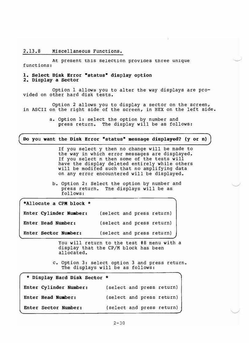
2.13.8 Miscellaneous Functions.
At present thiS selection provides three unlquefunctions:
1. Select Disk Error ·status· display option2. Display a Sector
Option 1 allows you to alter the way displays are provided on other hard disk tests.
Option 2 allows you to display a sector on the screen,in ASCII on the right side of the screen, in HEX on the left side.
a. Option 1: select the option by number andpress return. The display will be as follows:
Do you want the Disk Error ·status· message displayed? (y or n)
If you select y then no change will be made tothe way in which error messages are displayed.If you select n then some of the tests willhave the display deleted entirely while otherswill be modifed such that no amplifying dataon any error encountered will be displayed.
b. Option 2: Select the option by number andpress return. The displays will be asfollows:
*Allocate a CPR block *
'--...-'
~
Enter Cylinder Nw.ber:
Enter Head Number:
Enter Sector Nw.ber:
(select and press return)
(select and press return)
(select and press return)
You will return to the test #8 menu with adisplay that the CP/M block has beenallocated.
c. Option 3: select option 3 and press return.The displays will be as follows:
* Display Bard Disk Sector *
Enter Cylinder Number:
Enter Bead Ru.ber:
Enter Sector Number:
(select and press return)
(select and press return)
(select and press return)
2-30
"---/

2.13.8 --Continued.
The contents of that sector will be displayed, inhex on the left side of the screen, and in ASCIIon the right side.
TO return to test *8 menu press any key.
To terminate test *8 select option 4 and press return.The display will return to the hard disk test menu.
2-31

Tests 9,10,11 and 12 pertain to non-floppy units.If the diagnostic area of the disk is not formatted. you willsee the screen display:DIAGNOSTIC AREA SECTOR I NOT FORMATTED.
2.13.9 Hard Test 9--Copy Diagnostics to Hard Disk.~
If your diagnostic area is formatted, you will seethe screen display:
1. COpy DIAGNOSTICS FROM TAPE TO BARD DISK2. COPY DIAGNOSTICS FROM DISKETTE TO BARD DISK3. REFORMAT BARD DISK DIAGNOSTIC AREA AND COpy DIAGNOSTIC FROM
TAPE4. REFORMAT BARD DISK DIAGNOSTIC AREA AND COPY DIAGNOSTIC FROM
DISKETTE
SELECT REQUIRED FUNCTION BY NUMBER:
Select the function and procede with the copy onto the hard disk ••••• DIAGNOSTIC AREA CLEAR COMPLETED
COPYING FROM TAPE:•••••
• • • • DIAGNOSTIC COPY COMPLETED
After the diagnostics are copied onto the hard disk, you willreturn to the HARDS8 Menu.
2-32
v

2.13.10 Hard Test 10--Initialize Hard Disk System Track.
Your system should have the OASIS operating systemon it as well as the diagnostics. To initialize the HardDisk system track for CP/M and MP/M, select Option 10. Thescreen will display the following:
****Diagnostic Area Not Defined (Track H, Sector H)
To the prompts below input the following values:
Enter Diagnostic Cylinder Number: 250 <CR>
Enter Diagnostic Head Number: B <CR>
Enter Number of Daignostic Tracks: 24 <CR>
Enter Operating System Type (Number) B <CR>
At this point it is not necessary to specify anoperating system; However, to complete the test you mustenter a value (~,l,~,or 3). If you do not wish to specifythe operating system. enter 0. If you enter 1. you arespecifying CP/M; entering 2 specifies MP/M and entering3 specifies OASIS.
When the test is completed, you will see thefollowing display:
•••• System Track Initialization Ca.pleted
The Hard Disk (8 n) Test Facility will again corne on the screen.
2-33

2.13.11 Hard Test ll--Copy system to Hard Disk
This function allows you to initialize the harddisk with a CP/M or MP/M operating system. When you selecttest 11 of HARDS8, one of two prompts will appear:
PROMPT 1
1. Copy System fro. Tape to Bard Disk2. Copy System from Diskette to Bard Disk
Select required function by nuaber:
If you receive the above two prompts, proceed with the test.
PROMPT 2
ENTER DIAGNOSTIC CYLIBDER NUMBER: <CR>
ENTER DIAGNOSTIC BEAD NUMBER: <CR>
ENTER NUMBER OF DIAGNOSTIC TRACKS: <CR>
ENTER OPERATIRG SYSTEM TYPE (NUMBER):<CR>
If you receive the above 4 prompts, do not go any furtheruntil you consult with your distributor or Altos CustomerService 408-946-6700.
***PROCEED WITH THE TEST***
Currently, the facility only allows you to copy the systemfrom the tape unit, so select option 1. Before pressingreturn, remove the diagnostic loader tape and placethe systea tape into the drive. Wait for menu todisplay. Reset the computer and allow the boot from thehard disk. You should receive the MP/M prompt SA>
Note that since there are no floppy drives on theACS8~00-10/MTU the drive designations on the hard diskare as follows:
a. Logical drives A and B are associated withthe first hard disk. Drive A has a formattedcapacity of approximately 8 MBytes. Drive Bhas a formatted capacity of approximately290 KBytes.
b. Logical drives C and D are associated withthe second hard disk. Drive C has a formattedcapacity of approximately 8 MBytes. Drive Dhas a formatted capacity of approximately290 KBytes.
2-34
-../
'-.J
'-..../

2.13.12 Hard Test 12--Assign Diagnostic Area.
It you must assign a new diagnostic area on thehard disk, select test 12. You will see the followingdi~p1ay:
CURRENT DIAGNOSTIC AREACYLINDER: 250* HEAD: 0* NUMBER OF DIAGNOSTIC TRACKS: 24*
OPERATING SYSTEM: N*
DO YOU WISH TO CHARGE THE CURRENT DEFIRITION (Y or N):<CR>
* these values are standard.
If you entered Y to the above prompt, the following promptswill appear on the screen:
ENTER DIAGNOSTIC CYLIRDER NUMBER:
ENTER DIAGNOSTIC HEAD NUMBER:
ENTER NUMBER OF DIAGNOSTIC TRACKS:
••• DIAGNOSTIC AREA ASSIGNMENT COMPLETED
Atter this test is successfully completed, you willbe given the HARDS8 menu on the screen.
2-35