C 1 U. S. RIFLE - ImageEventphotos.imageevent.com/badgerdog/generalstorage/tm9270usriflecal30... ·...
30
Transcript of C 1 U. S. RIFLE - ImageEventphotos.imageevent.com/badgerdog/generalstorage/tm9270usriflecal30... ·...

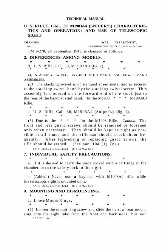
TECHNICAL MANUAL
U. S. RIFLE, CAL. .30, M1903A4 (SNIPER'S) CHARACTERISTICS AND OPERATION; AND USE OF TELESCOPIC SIGHT
CHANGES WAR DEPARTMENT,
No. 1 WASHINGTON 25, D. C , 4 March 1944.
TM 9-270, 28 September 1943, is changed as follows:
2. DIFFERENCES AMONG MODELS. * * * * * * *
5 7 7 3 1 7 — 4 4
d. U. S. Rifle, Cal. .30, M1903A3 (fig. 2). * * * * * * *
(4) STACKING SWIVEL, BAYONET STUD BAND, AND LOWER BAND
ASSEMBLIES.
(a) The stacking swivel is of stamped sheet metal and is secured to the s t ack ing swivel b a n d by t h e s t a c k i n g swivel screw. Th i s assembly is moun ted on t h e forward end of t h e stock just to the rear of the bayonet stud band. In the M1903 * * * M1903A3 Rifle.
* * * * * * * e. U. S. Rifle, Cal. .30, M1903A4 (Sn ipe r ' s ) (fig. 1). * * * * * * *
(5) Due to the * * * for the M1903 Rifle. Caution: The f ront a n d rea r g u a r d screws should be removed or loosened only when necessary. T h e y should be kep t as t i g h t as possible a t a l l t imes a n d t h e r if leman should check t h e m frequent ly . Af ter t i g h t e n i n g or rep lac ing gua rd screws, t h e rifle should be zeroed. (See par . 10d ( 1 ) ( c ) . )
[A. G. 300.7 (17 Nov 43) . ] (C 1, 4 Mar 44.)
7. INDIVIDUAL SAFETY PRECAUTIONS. * * * * * * *
e. If it is desired to carry the piece cocked with a cartridge in the chamber, t u r n t he safe ty lock to t h e r igh t .
• • • • * • • k. (Added.) Never use a bayonet with M1903A4 rifle while
the telescopic sight is mounted on it. [A. G. 300.7 (17 Nov 43) . ] (C 1, 4 Mar 44.)
9. MOUNTING AND DISMOUNTING. * * * * * * *
c. Loose Moun t R i n g s . * * * * * * *
(1) Loosen the mount ring screw and slide the narrow rear mount ring onto the sight tube from the front and back nea r , b u t not
TM 9-270 C 1 U. S. RIFLE
against, the adjustment plate on the rear end of the tube. Turn the ring * * * mount ring screw.
* * * * * • • (A. G. 300.7 (17 NOT 43) . ] (C 1, 4 Mar 44.)
10. ADJUSTMENTS. * * * * * * *
e. Setting Sight. * * * * * * *
(2) A simple method for using the M1903A4 Rifle is to target the rifle at some intermediate range (such as 200, 250, or 300 yards, or any other range tha t seems desirable) and set the sight for this range. Then hold over * * * determined by practice.
[A. G. 300.7 (17 Nov 43) . ] (C 1, 4 Mar 44.)
11. PARALLAX ADJUSTMENT. * * * * * * *
b. (Superseded.) To test for parallax— (1) Place the sight on a rigid support, focus the sight and align
the reticle on a mark about 100 yards distant. (2) While looking through the sight, move the head from side to
side. If there is any apparent movement between the reticle and the mark, parallax is present. Correction for parallax may be made by ordnance maintenance personnel only.
* * * * * * * [A. G. 300.7 (17 Nov 43) . ] (C 1, 4 Mar 44.)
BY ORDER OF THE SECRETARY OF WAR :
G. C. MARSHALL, Chief of Staff.
OFFICIAL:
J. A. ULIO, Major General,
The Adjutant General.
2 U.S. GOVERNMENT PRINTING OFFICE: 1944

NOTES

TM 9-270 2
U. S. RIFLE, CAL. .30, M1903A4 (SNIPER'S) CHARACTERISTICS AND OPERATION; AND USE OF TELESCOPIC SIGHT
4

TM 9-270 2
INTRODUCTION
Figure 3 - Rear Sight for U.S. Rifle, Cal. .30, M1903A3
(1) STOCK. The stock is similar to that of the M1903 Rifle, except that the pistol grip is optional on the M1903A3, whereas the M1903 did not have the pistol grip. Some of the M1903A3 Rifles issued had front and rear stock screw pins running laterally through the center portion of the stock to reinforce the trigger guard and magazine aperture in place of the front and rear stock screws and nuts assembled to the M1903 Rifle. Front and rear stock screws and nuts are now standard for the Ml903A3 Rifle.
(2 ) REAR SIGHT. In this rifle, the folding leaf type of rear sight, and fixed base, used on the M1903 and M1903A1 Rifles, are removed from the rear end of the barrel, and a rigid, wing-type of rear sight is assembled to the bridge of the receiver (fig. 3) . This sight consists of a base, windage yoke, slide aperture, spring, and windage index knob. The range scale on the windage yoke is marked in 100-yard graduations, and has 50-yard adjustments. The slide aperture can be moved up and down this scale for various ranges. Turning the windage index knob moves the yoke to the right or left to allow for windage. Each click represents a change of 1 minute of angle or a horizontal change of impact of 1 inch at a range of 100 yards. Each division or mark on the windage scale represents 4 minutes of angle or a change in the point of impact of 4 inches at a range of 100 yards.
5

TM 9-270 2
U. S. RIFLE, CAL. .30, M1903A4 (SNIPER'S) CHARACTERISTICS AND OPERATION; AND USE OF TELESCOPIC SIGHT
( 3 ) BARREL GUARD. In this rifle, a barrel guard extending from the upper (bayonet stud) band to the front face of the receiver, takes the place of the hand guard on the M1903 Rifle which extended from the upper band to the front face of the fixed base of the rear sight mounted on the rear end of the barrel.
( 4 ) STACKING SWIVEL, BAYONET STUD B A N D , AND LOWER B A N D
ASSEMBLIES.
(a) The stacking swivel is of stamped metal and secured to the forward end of the stock, just to the rear of the bayonet stud band, by the stacking swivel band. In the M1903 Rifle the stacking swivel is of round wire and pivoted to the upper band, which corresponds to the bayonet stud band of the M1903 A3 Rifle.
(b) The bayonet stud band is shorter than the upper band of the M1903 Rifle, is solid on top, and has two bayonet mounting lugs on the bottom. In the M1903 Rifle, there is an opening in the top of the upper band, and but one bayonet lug.
(c) The lower band swivel is a flat metal stamping pivoted in a flat lower band. The swivel in the M1903 Rifle is of round wire, and the lower band is grooved for reinforcement. For disassembly and assembly see FM 23-10.
( 5 ) TRIGGER GUARD MAGAZINE.
(a) The magazine, trigger guard, and floor plate are of stamped sheet metal staked and welded together to form a single unit, and called the "trigger guard magazine assembly." In the M1903 Rifle, the magazine and trigger guard are an integral machined piece called the "trigger guard", and the floor plate is a separate machined piece assembled to the bottom of the magazine section of the trigger guard by means of a spring-operated catch assembled to the trigger guard.
(b) In the M1903 Rifle, the magazine spring is clipped to the follower and floor plate, and the spring and follower are removed from the receiver together with the floor plate by disengaging the floor plate catch. In the M1903A3 Rifle, the magazine spring is clipped to the follower only, which is of slightly different design than that of the M1903 Rifle, and must be removed from the top opening of the magazine. The removal and replacement of this magazine spring and follower is easily accomplished by following the instructions outlined in sub steps (c) and (d) below; otherwise difficulty may be encountered.
(c) Removal of Follower. 1. Position rifle with muzzle to left. 2. Set cut-off at "ON" position. 3. Open bolt to extreme rearward position. 4. Insert nose of bullet directly in front of ejector and against
6
TM 9-270 2
INTRODUCTION
left side of follower rib. 5. Tip rear of follower downward and toward the right side of
the rifle until the front left side of the follower emerges through the magazine slot at the front of the receiver.
6. Move bolt forward slowly to disengage follower from magazine spring.
CAUTION: Do not allow front end of follower to strike mouth of chamber.
7. Open bolt and remove follower and magazine spring. N O T E : In some instances the follower assembly for the M1903
or M1903A1 Rifle will be found in an M1903A3 Rifle. To distinguish between the two followers, note that the follower for the M1903 and M1903A1 is machined from a piece of solid steel and has a raised pad which acts as a stop for the magazine spring, while the follower for the M1903A3 is formed of sheet metal. When it is found that the follower of the M1903 Rifle is being used in the M1903A3 Rifle, no attempt should be made to disassemble the follower as described in the above paragraphs, as serious damage to the chamber end of the barrel will result. Instead, the trigger guard magazine assembly must be removed in order to remove the follower (subpar. d (5) (a) above). In all other respects, followers of M1903 and M1903A3 Rifles are interchangeable. (For removal of trigger guard magazine assembly, see subpar. e (5) below.)
(d) Installation of Follower.
1. Position rifle with muzzle to the left. 2. Insert small end of magazine spring under ears of follower and
slide fully forward. 3. Compress magazine spring against follower and insert spring
and follower sidewise into magazine opening of receiver with small end of follower toward the front and with spring toward left side of receiver.
4. Rotate follower so that rib will project upward. 5. Press rear end of follower down to bottom of magazine in order
to insure seating of spring under ears of follower.
e. U. S. Rifle, Cal. .30, M1903A4 (Sniper's) (fig. 1). This rifle was designed for "sniping" and is identical with the Ml903A3 Rifle, described in subparagraph d above, with the following exceptions:
(1) A telescopic sight is mounted to the top of the receiver in place of the fixed, wing-type rear sight mounted on the M1903A3 Rifle.
(2) The front sight group is entirely removed from the barrel.
(3) The stock is the same as that of the M1903A1 Rifle, having pistol grip and the front and rear stock screws and nuts, in place of a
7
TM 9-270 2 - 3
U. S. RIFLE, CAL. .30, M1903A4 (SNIPER'S) CHARACTERISTICS AND OPERATION; AND USE OF TELESCOPIC SIGHT
straight grip and front and rear stock pins as in the M1903A3 Rifle (par. 2 d (1) ).
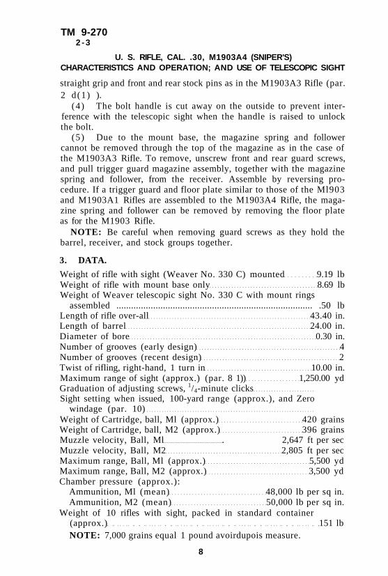
(4) The bolt handle is cut away on the outside to prevent interference with the telescopic sight when the handle is raised to unlock the bolt.
(5) Due to the mount base, the magazine spring and follower cannot be removed through the top of the magazine as in the case of the M1903A3 Rifle. To remove, unscrew front and rear guard screws, and pull trigger guard magazine assembly, together with the magazine spring and follower, from the receiver. Assemble by reversing procedure. If a trigger guard and floor plate similar to those of the Ml903 and M1903A1 Rifles are assembled to the M1903A4 Rifle, the magazine spring and follower can be removed by removing the floor plate as for the M1903 Rifle.
NOTE: Be careful when removing guard screws as they hold the barrel, receiver, and stock groups together.
3. DATA.
Weight of rifle with sight (Weaver No. 330 C) mounted 9.19 lb Weight of rifle with mount base only 8.69 lb Weight of Weaver telescopic sight No. 330 C with mount rings
assembled ................................................................................ .50 lb Length of rifle over-all 43.40 in. Length of barrel 24.00 in. Diameter of bore 0.30 in. Number of grooves (early design) 4 Number of grooves (recent design) 2 Twist of rifling, right-hand, 1 turn in 10.00 in. Maximum range of sight (approx.) (par. 8 1)) 1,250.00 yd Graduation of adjusting screws, 1/4-minute clicks Sight setting when issued, 100-yard range (approx.), and Zero
windage (par. 10) Weight of Cartridge, ball, Ml (approx.) 420 grains Weight of Cartridge, ball, M2 (approx.) 396 grains Muzzle velocity, Ball, Ml . 2,647 ft per sec Muzzle velocity, Ball, M2 2,805 ft per sec Maximum range, Ball, Ml (approx.) 5,500 yd Maximum range, Ball, M2 (approx.) 3,500 yd Chamber pressure (approx.):
Ammunition, Ml (mean) 48,000 lb per sq in. Ammunition, M2 (mean) 50,000 lb per sq in.
Weight of 10 rifles with sight, packed in standard container (approx.) 151 lb NOTE: 7,000 grains equal 1 pound avoirdupois measure.
8

TM 9-270 4
INTRODUCTION
4. PRECAUTIONS.
a. The following precautions are referred to at this point for emphasis. They apply to the paragraphs indicated, and such paragraphs should be read carefully with precautions in mind.
(1) Do not allow front end of follower to strike mouth of chamber (par. 2 d (5) (c) 6 ) .
(2) Individual safety precautions are as listed in paragraph 7. (3 ) Do not remove the eyepiece from the sight tube as dust may
enter, or the cross hairs may be damaged. It should not be unscrewed more than 1/2 inch from the all-the-way-on position (par. 10 b (4 ) ).
(4) Do not turn the left lateral adjusting screw. It is permanently staked in position so that it will not have to be adjusted each time the mount is installed on the mount base. If the left lateral adjusting screw is turned, the above method of attaining zero windage will not be correct (par. 10 c ( 2 ) ) .
(5) Parallax may be present in a sight at a short range (25 yards or less) and not at longer ranges. In such a case, no correction for parallax is needed if it is correct for ranges used (par. 11 b ) .
(6) The mount ring screws should be drawn down sufficiently to hold the sight firmly in place, but not too tight If screws are drawn down too tight, the sight tube may become bent or the reticle and lens elements be thrown out of adjustment (par. 12 a ) .
9

TM 9-270 5 - 6
U. S. RIFLE, CAL. .30, M1903A4 (SNIPER'S) CHARACTERISTICS AND OPERATION; AND USE OF TELESCOPIC SIGHT
Section II
OPERATION AND CARE OF THE RIFLE Paragraph
General 5
Operation of the rifle 6
Individual safety precautions 7
5. GENERAL.
a. The operation, care, maintenance, disassembly, and assembly of the M1903A4 (Sniper's) Rifle is identical with that of the M1903 and M1903A1 Rifles covered in FM 23-10 with the following exceptions :
(1) The lower band assembly is removed and reinstalled as described for the M1903A3 Rifle in FM 23-10.
(2) The magazine spring and follower should be removed and reinstalled as described in paragraph 2 e (5) . When removing and reinstalling these parts the telescopic sight should be removed from the mount base as described in paragraph 9 b. (The mount base is alined at manufacture and the screws staked in, and should not be removed by using arms.)
(3) The telescopic sight is removed from, and reinstalled on the mount base as described in paragraph 9.
b. This rifle can be operated as a single loader by placing one cartridge directly into the chamber, or the magazine can be filled by removing the five cartridges from the clip and loading them separately into the magazine. Operation of this rifle is the same as for the M1903 and M1903A1 Rifles covered in FM 23-10. For convenience, operation as applied to this rifle is given in paragraph 6.
6. OPERATION OF THE RIFLE.
a. Loading. To load the magazine, turn the cut-off up, showing "ON;" draw the bolt fully to the rear; then insert the cartridges singly from the hand, pressing the cartridges down with the thumb into the magazine until caught by the edges of the receiver. To place a round in the chamber, close the bolt. As the bolt is closed, the top cartridge in the magazine is pushed forward into the chamber. When the rifle is used as a single loader, cartridges are inserted directly into the chamber with the hand, the cut-off being turned down.
10

TM 9-270 6
OPERATION AND CARE OF THE RIFLE
b. Aiming. The eye should be placed as close to the eyepiece as possible and yet have a maximum field of view through the sight, but not so close as to risk injury when the rifle recoils. If the eye is placed too close to the eyepiece the field of view will diminish. Adjust the sight and aim in accordance with instructions in paragraph 10.
NOTE: To prevent reflected sunlight from blurring vision or disclosing the sniper's position, a lens hood may be improvised by tightly wrapping a strip of dull black paper or similar material around the front end of the sight tube, fastening the strip, and then sliding it out beyond the end of the tube an inch or more to shade the lens.
c. Extraction. Extraction of the empty case from the chamber by the extractor is started during the rotation of the bolt and is completed as the bolt is drawn to the rear.
d. Ejection. When the bolt is drawn fully to the rear the head of the case strikes against the ejector point and the case is ejected from the receiver.
e. Cut-off. When the cut-off is up ("ON"), and the bolt fully to the rear, the top cartridge in the magazine is forced up into the path of the bolt by the magazine spring. When the cut-off is turned down, the magazine is "OFF." The bolt cannot be drawn fully back, and its front end, projecting over the rear end of the upper cartridge, holds the latter down in the magazine below the action of the bolt. The magazine mechanism then remains inoperative, and the rifle can be used as a single loader with the cartridges in the magazine held in reserve.
f. Follower. In magazine fire, after the last cartridge has been fired and the bolt drawn fully to the rear, the follower rises and blocks the path of the bolt, thus showing that the magazine is empty. Five cartridges may then be inserted to fill the magazine, or the bolt may be closed without reloading by first forcing the follower down until it is below the path of the bolt.
g. Unloading. With the cut-off up ("ON"), move the bolt forward and back until no cartridges remain in the magazine or chamber.
h. Safety Device. To set at "SAFE," which can only be done when the piece is cocked, turn the safety lock to the right against the body of the telescopic sight. This locks the firing pin in position and the rifle cannot be fired. To set at "READY," turn the safety lock to the left.
i. Cocking. The rifle may be cocked either by raising the bolt handle until it strikes the left side of the receiver and then turning it down, or by pulling the cocking piece directly to the rear.
11

TM 9-270 7
U. S. RIFLE, CAL. .30, M1903A4 (SNIPER'S) CHARACTERISTICS AND OPERATION; AND USE OF TELESCOPIC SIGHT
a. Consider every rifle to be loaded until you have examined it and proved it to be unloaded. Never trust your memory as to its condition in this respect.
b. Never point the rifle at anyone you do not intend to shoot, nor in a direction where an accidental discharge may do harm.
c. Always unload the rifle if it is to be left where someone else may handle it.
d. Always point the rifle up when snapping the trigger after examination.
e. If it is desired to carry the piece cocked with a cartridge in the chamber, the bolt mechanism should be secured by turning the safety lock to the right.
f. Under no circumstances should the firing pin be let down by hand on a cartridge in the chamber.
g. Never fire a rifle with any grease, cleaning patch, dust, dirt, mud, snow, or other obstruction in the bore. To do so may burst the barrel.
h. Never grease or oil the ammunition or the walls of the rifle chamber. This creates a hazardous pressure on the rifle bolt.
i. See that the ammunition is clean and dry. Examine all live and dummy ammunition. Turn in all cartridges with loose bullets or which appear to be otherwise defective.
j. Do not allow the ammunition to be exposed to the direct rays of the sun for any length of time. This creates hazardous chamber pressures.
12
7. INDIVIDUAL SAFETY PRECAUTIONS.
TM 9-270 8
Section III
WEAVER TELESCOPIC SIGHT NO. 330 C Paragraph
Description 8
Mounting and dismounting 9
Adjustments 10
Parallax adjustment 11
Placing reticle vertical 12
Care and cleaning 13
Care and cleaning in cold and hot climates 14
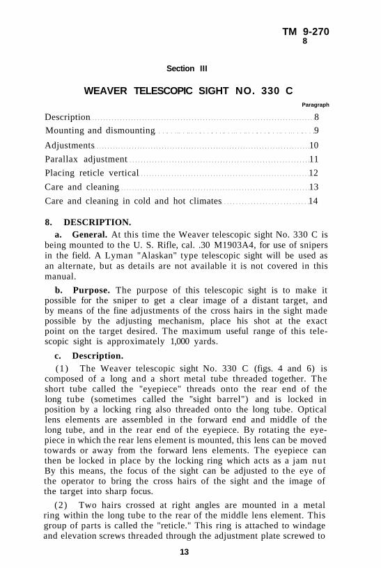
8. DESCRIPTION. a. General. At this time the Weaver telescopic sight No. 330 C is
being mounted to the U. S. Rifle, cal. .30 M1903A4, for use of snipers in the field. A Lyman "Alaskan" type telescopic sight will be used as an alternate, but as details are not available it is not covered in this manual.
b. Purpose. The purpose of this telescopic sight is to make it possible for the sniper to get a clear image of a distant target, and by means of the fine adjustments of the cross hairs in the sight made possible by the adjusting mechanism, place his shot at the exact point on the target desired. The maximum useful range of this telescopic sight is approximately 1,000 yards.
c. Description. (1) The Weaver telescopic sight No. 330 C (figs. 4 and 6) is
composed of a long and a short metal tube threaded together. The short tube called the "eyepiece" threads onto the rear end of the long tube (sometimes called the "sight barrel") and is locked in position by a locking ring also threaded onto the long tube. Optical lens elements are assembled in the forward end and middle of the long tube, and in the rear end of the eyepiece. By rotating the eyepiece in which the rear lens element is mounted, this lens can be moved towards or away from the forward lens elements. The eyepiece can then be locked in place by the locking ring which acts as a jam nut By this means, the focus of the sight can be adjusted to the eye of the operator to bring the cross hairs of the sight and the image of the target into sharp focus.
(2) Two hairs crossed at right angles are mounted in a metal ring within the long tube to the rear of the middle lens element. This group of parts is called the "reticle." This ring is attached to windage and elevation screws threaded through the adjustment plate screwed to
13

U. S. RIFLE, CAL. .30, M1903A4 (SNIPER'S) CHARACTERISTICS AND OPERATION; AND USE OF TELESCOPIC SIGHT
14

TM 9-270 8
WEAVER TELESCOPIC SIGHT NO. 330 C
the outside of the long tube to cover the assembly aperture (figs. 4 and 7). The diameter of the ring is less than the inside diameter of the tube, thus it can be moved up and down and right and left for adjustment of the cross hairs (reticle) by means of the adjusting screws. When sighting the rifle, the point of intersection of the crossed hairs is laid on the point of the target to be shot at, and should coincide with the desired point of impact of the bullet.
(3) A knurled knob forms the head of the elevation and windage screws (fig. 7). The outside diameter of the knobs is divided into sixty 1/4-minute click notches. The screws are held in adjustment by a click spring screwed to the adjustment plate and engaging with the click notches. The faces of the knobs are divided into fifteen divisions, each of which represents four 1/4-minute clicks. Arrows stamped on the knobs indicate the direction in which the screws must be turned to elevate the point of impact of the bullet ("UP"), or move it to the left ("L") for windage correction. To lower the point of impact, or move it to the right, the screws must be turned in the opposite direction to that in which the arrow points.
(4) The telescopic sight is mounted to the receiver of the rifle by means of front and rear mount rings which fit on the long tube and are clamped by screws (fig. 4 ) . The front ring is clamped by two screws and the rear ring by one screw. There is a dovetailed lug on the bottom of the front mount ring and a flat lug on the rear mount ring, for the purpose of securing the rings and sight to the mount base which is permanently secured to the top of the receiver by screws staked in position at manufacture.
(5) The mount base (fig. 4) is an oblong piece of metal fastened to the top of the receiver by a screw in each end. In the lower face of the rear end of the base a slot is cut which mates with the dovetailed lug machined on the top of the receiver bridge and to which the rear sight of the M1903A3 Rifle is mounted when assembled. The lower face of the front end of the base is machined on a curve to fit the curve of the front end of the receiver. A thin metal shim of the proper thickness is placed between the mount base and the receiver at the front or rear end to level the base with regard to the receiver and bore line. These shims range in thickness from 0.005 ± 0.001 inch to 0.020 ± 0.001 inch. A front mount base screw is threaded through the front end of the base, and then into the receiver. This screw secures the front end of the base and acts as a pivot. The rear end of the base fits comparatively loosely on the dovetailed lug on the bridge of the receiver and can be shifted slightly from side to side on the lug. By this means, the base is alined at manufacture, so that the sight when mounted will coincide with the bore line of the rifle barrel. A rear mount base screw is threaded through the rear end of the base and into the dovetailed lug on the receiver bridge, thus securing the rear end of the base
15

TM 9-270 8
U. S. RIFLE, CAL. .30, M1903A4 (SNIPER'S) CHARACTERISTICS AND OPERATION; AND USE OF TELESCOPIC SIGHT
16

TM 9-270 8 - 9
WEAVER TELESCOPIC SIGHT NO. 330 C
and maintaining the alignment. An undercut recess is cut in the front end of the base in which the mounting lug on the front mount ring on the sight engages when mounted.
(6 ) A lateral adjusting screw is threaded into the right and left sides of the mount base at the rear end. The cupped heads of these screws bear in radial notches in the flat lug on the rear mount ring attached to the sight when assembled to the base, thereby holding the rear end of the sight down on the base. By means of these two screws the rear mount ring can be shifted laterally thereby swinging the alignment of the sight to left or right to aline for "zero windage" (bore line) of the rifle with which it is used. The rifle is zeroed for windage at manufacture and the left lateral adjusting screw is staked in place and should not be shifted or removed. Further adjustments for windage are made by means of the windage screw on the left side of the sight
(7) The sight, with mount rings attached, is mounted to the mount base by means of the dovetailed lug on the front mount ring engaging in the undercut mating recess in the mount base, and the two lateral adjusting screws on the base which engage notches in the sides of the lug on the rear mount ring as explained above. Mounting, dismounting, and adjustment of the sight are explained in paragraphs 9 and 10.
(8) Two leather lens caps connected by a strap are issued with the sight to protect the lenses when not in use. The use of these caps is explained in paragraph 9 a (5) and shown in figure 6.
9. MOUNTING AND DISMOUNTING.
a. Mounting. (1) Remove the right lateral adjusting screw from the mount
base. (2) Grasp the sight immediately behind the front mount ring.
Hold the sight crosswise to the rifle with the eyepiece pointing to the right (bolt handle side of receiver), and engage the lug on the front mount ring in the undercut mating recess in the front end of the mount base.
(3 ) Press the mount ring down firmly to level and engage the lug, and swing the rear (eyepiece) end of the sight (clockwise) towards the rear end of the receiver, until the lug on the rear mount ring rests on the flat of the mount base and against the left lateral adjusting screw staked in the mount base. Figure 5 shows sight partially mounted.
(4) Thread in the right lateral adjusting screw until the rear mount ring is held firmly between the two screws. Be sure the edges of the screws engage in the radial notches in the lug of the rear mount ring.
17

TM 9-270 9
U. S. RIFLE, CAL. .30, M1903A4 (SNIPER'S) CHARACTERISTICS AND OPERATION; AND USE OF TELESCOPIC SIGHT
Figure 6 — Weaver Telescopic Sight No. 330 C — Showing Lens Caps in Position
NOTE: It may be necessary to lift the rear end of sight slightly when sliding the lug of the rear mount ring onto the mount base. Do not strain.
(5) When the sight is mounted, place the larger of the two leather lens caps over the eyepiece and the smaller over the front end of the sight. Then turn the front cap, twisting the strap around the sight tube until it draws the two caps snugly together. Removal is accomplished by reversing the procedure. Figure 6 shows caps in place.
b. Dismounting. (1 ) Remove the right lateral adjusting screw from the mount base. (2) Grasp the sight immediately behind the front mount ring, and
swing the rear (eyepiece) end of the sight out and away from the receiver on the bolt handle side, until the sight is at right angles to the mount base.
(3) Lift the sight upward from the mount base thus disengaging the front mount ring lug from the undercut recess in the mount base.
(4) Thread in the right lateral adjusting screw to prevent losing it
c. Loose Mount Rings. The front and rear mount rings are adjusted and clamped to the sight at manufacture and should not be removed. If these rings should become loose or detached while the
18
TM 9-270 9-10
WEAVER TELESCOPIC SIGHT NO. 330 C
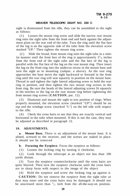
sight is dismounted from the rifle, they can be assembled to the sight as follows:
(1) Loosen the mount ring screw and slide the narrow rear mount ring onto the sight tube from the front end and back against the adjustment plate on the rear end of the tube. Turn the ring until the flat face of the lug is on the opposite side of the tube from the elevation screw marked "UP." Then tighten the mount ring screw.
(2 ) Slide the broad, front mount ring onto the sight tube in a similar manner until the front face of the ring is approximately 31/4 inches from the front end of the sight tube and the flat face of the lug is parallel with the flat face of the lug on the rear mount ring. Then insert the lug on the front ring into the undercut recess in the mount base and turn the sight as in mounting (subpar. a above). As the rear ring approaches the base move the sight backward or forward in the front ring until the rear ring will seat squarely in position on the mount base. Thread in and tighten the right lateral adjusting screw to hold the rear ring in position, and then tighten the two mount ring screws in the front ring. Be sure the heads of the lateral adjusting screws fit squarely in the notches in the lug on the rear mount ring before tightening the front mount ring screws (CAUTION , par. 12).
(3) Dismount and mount the sight to test position of rings. When properly mounted, the elevation screw (marked "UP") should be on top and the windage screw (marked "L") on the left side with respect to the rifle.
(4) Check the cross hairs to see that they are exactly vertical and horizontal in the tube when mounted. If this is not the case, they may be adjusted as described in paragraph 12.
10. ADJUSTMENTS.
a. Mount Base. There is no adjustment of the mount base. It is alined, screwed to the receiver, and the screws are staked in place. It should not be removed
b. Focusing the Eyepiece. Focus the eyepiece as follows: (1) Loosen the locking ring by turning it clockwise. (2) Look through the telescope at an object not less than 100
yards distant. (3) Turn the eyepiece counterclockwise until the cross hairs are
quite blurred. Then turn the eyepiece clockwise until the cross hairs are in sharp focus with respect to the image of the object
(4) Hold the eyepiece and screw the locking ring up against it. CAUTION: Do not remove the eyepiece from the sight tube as
dust may enter and the cross hairs may be damaged. It should not be unscrewed more than 1/2 inch from the all-the-way-on position.
19

TM 9-270 10
U. S. RIFLE, CAL. .30, M1903A4 (SNIPER'S) CHARACTERISTICS AND OPERATION; AND USE OF TELESCOPIC SIGHT
Figure 7 — Weaver Telescopic Sight No. 330 C — Showing Adjustments
c. Windage Adjustment (fig. 7). (1) Adjust the sight for zero windage as follows: (a) Turn the windage screw (marked "L") clockwise (as indi
cated by arrow) as far as it will go. (b) Turn it counterclockwise until the index points to "0" on
the windage screw and continue to turn it two complete turns. (2) The windage screw can then be turned clockwise or coun
terclockwise for variations in windage. When the screw is turned, each click represents 1/4 minute, or shift of the point of impact of the bullet on the target of 1/4 inch for each 100 yards. For example: One click will shift the point of impact of the bullet 1/4 inch at 100 yards; 1/2 inch at 200 yards; 3/4 inch at 300 yards, etc. Turning the windage screw in the direction indicated by the arrow on the screw will shift the point of impact of the bullet to the left; turning it in the opposite direction will shift the point of impact to the right
CAUTION: Do not turn the left lateral adjusting screw. It is permanently staked in position so that it will not have to be adjusted each time the mount is installed on the mount base. If the left lateral adjusting screw is turned, the above method of obtaining zero windage will not be correct.
20

TM 9-270 10
WEAVER TELESCOPIC SIGHT NO. 330 C
d. Elevation Adjustment (fig. 7). (1) Adjust the elevation screw for 100 yards range as follows: (a) Turn the elevation screw (marked "UP") clockwise (as in
dicated by arrow) as far as it will go. (b) Turn it counterclockwise until the index points to "0" on the
elevation screw and then continue to turn it four complete turns. This is the approximate setting for 100 yards range.
(c) To obtain the exact setting, it is necessary to zero-in the rifle at 100 yards by actual firing; that is, find the setting of the sight such that the average point of impact coincides with point of aim at 100 yards. (See FM 23-10 for zeroing-in of rifles.)
(2) The elevation screw can then be turned clockwise for ranges greater than 100 yards. Each click represents 1/4-minute change in angle of elevation or a shift of 1/4 inch on the target for each 100 yards. Turning the elevation screw in the direction of the arrow on the screw will shift the point of impact of the bullet upward; turning the screw in the opposite direction will shift the point of impact of the bullet downward.
e. Setting Sight. (1) The firing table below gives approximate sight settings for
various ranges up to 1,000 yards. This firing table does not take into account such factors as direction and velocity of wind, slope of terrain, etc.; consequently the values are not absolute. However, it will serve as a guide in finding sight settings after ranges have been estimated. If the bullet does not hit the target, readjust the sight setting.
FIRING TABLE FOR WEAVER TELESCOPIC SIGHT NO. 330 C
Range
(yards)
Angle of Elevation
(min)
Sight-Setting
(dicks)
Difference
(dicks)
Drift Right (min)
Correction
left (clicks)
100 2.4 *0 11
12
13
17
19
22
26
31
37
0 0
200 5.1 11 11
12
13
17
19
22
26
31
37
0 0
300 8.1 23
11
12
13
17
19
22
26
31
37
0 0
400 11.5 36
11
12
13
17
19
22
26
31
37
0.3 1
500 15.5 53
11
12
13
17
19
22
26
31
37
0.3 1
600 20.3 72
11
12
13
17
19
22
26
31
37
0.7 2
700 26.0 94
11
12
13
17
19
22
26
31
37
0.7 2
800 32.4 120
11
12
13
17
19
22
26
31
37
0.7 3
900 40.2 151
11
12
13
17
19
22
26
31
37 1.0 4
1,000 49.3 188
11
12
13
17
19
22
26
31
37 1.4 5
* 0 (Zero) is the setting such that point of impact coincides with point of aim at 100 yards (subpar. d (1) (c) above).
21

TM 9-270 10-12
U. S. RIFLE, CAL. .30, M1903A4 (SNIPER'S) CHARACTERISTICS AND OPERATION; AND USE OF TELESCOPIC SIGHT
E X A M P L E : Assuming the bullets are striking 4 inches to the right and 2 inches low at a 200-yard range, turn the windage screw 8 clicks in the direction of the arrow and turn the elevation screw 4 clicks in the direction of the arrow. If the bullets are striking to the left and high, turn the screws in the opposite direction.
(2 ) A simple method for using the M1903A4 Rifle is to target the rifle at some intermediate range such at 200, 250, or 300 yards and set the sight for this range. Then hold over the desired point of impact of the bullet at longer ranges and under for shorter ranges. The amount of hold-over or hold-under is determined by practice.
11. PARALLAX ADJUSTMENT.
a. The parallax of this telescopic sight is adjusted by movement of the reticle attached to the adjustment plate on the sight. Parallax is adjusted at manufacture and the plate screwed firmly in place, and under no circumstances should the plate be moved by using arms, nor the screws be allowed to become loose. If parallax develops, it will cause the reticle (cross hairs) to become blurred with respect to the target image. (This has no connection with the eyepiece or blurring of the target image due to improper adjustment of the eyepiece for focus.)
b. To test for parallax, place the sight on a rigid support with the reticle (cross hairs) alined on some mark. While looking through the sight, move the head from side to side. If there is any apparent movement between the reticle and the mark, parallax is present. Correction for parallax may be made by ordnance maintenance personnel only.
CAUTION: Parallax may be present in a sight at a short range (25 yards or less) and not at longer ranges. In such a case, no correction for parallax is needed if it is correct for ranges used.
12. PLACING RETICLE VERTICAL.
a. If the reticle should become shifted so that the cross hairs are not exactly vertical and horizontal, they may be so positioned by loosening the front and rear mount ring screws, turning the sight in the mount rings, and then tightening the screws. If it is not possible to adjust the hairs sufficiently in this manner, inform the responsible ordnance service.
CAUTION: The mount ring screws should be drawn down sufficiently to hold the sight firmly in place, but not too tight If screws are drawn down too tight, the sight tube may become bent or the reticle and lens elements be thrown out of adjustment.
22

TM 9-270 13
WEAVER TELESCOPIC SIGHT NO. 330 C
13. CARE AND CLEANING. a. General. The U. S. Rifle, cal. 30, M1903A4 with the Weaver
telescopic sight No. 330 C is issued to using arms with the sight dismounted from the base. The front and rear mount rings are attached to the sight and leather lens caps cover the front and rear end of the sight for protection. The mount base is staked in position on the receiver of the rifle at manufacture, and the left lateral adjusting screw staked in the base. Using arm personnel are required to mount the sight to the rifle as explained in paragraph 9.
b. Handling. (1) This telescopic sight is a delicate instrument and should be
handled with care at all times, whether mounted or dismounted, lest it be damaged or knocked out of adjustment. The sight should never be disassembled by using arm personnel nor the eyepiece removed. The locking ring should be kept turned up tight against the eyepiece to prevent it from working loose, and the mount base screws, mount ring screws, the adjustment plate attaching screws, and the left lateral adjusting screw, should be checked occasionally to make sure they are tight. The leather lens caps should be kept in place over the lenses when the rifle is not in actual use, in order to protect the lenses and keep out dust and moisture. The lenses should never be touched with the fingers, as grease or acid from perspiration will injure the lens.
(2 ) The sight should never be allowed to remain in direct sunlight, nor the sun's rays to shine on the lenses when in use. Direct rays of the sun or excessive heat will damage the lens elements. If exposed to the sun for a considerable period through necessity, the sight should be completely covered.
(3) If the locking ring is tight against the eyepiece and the leather lens caps in position, moisture should not be able to penetrate into the interior of the sight. When the rifle is carried in the rain, lens caps should be drained out often, or the lower cap removed so that accumulated water does not penetrate the lens mounting. A waterproof covering should be used under such circumstances, when possible.
(4) In case of gas or chemical attack, cover the sight completely. For defense against chemical attack, refer to FM 21-40. Decontaminate according to instructions contained in TM 3-220, "Chemical Decontamination Materials and Equipment"
c. Cleaning. Cleaning should be done with great care as the sight is a delicate mechanism.
( 1 ) T U B E . The outside of the tube may be cleaned by gently wiping with a clean dry lintless wiping cloth, to remove dust or moisture. When thoroughly cleaned, a very light coating of OIL, lubricating, preservative, light, may be applied to prevent rusting, but great care
23

TM 9-270 13-14
U. S. RIFLE, CAL. .30, M1903A4 (SNIPER'S) CHARACTERISTICS AND OPERATION; AND USE OF TELESCOPIC SIGHT
must be taken to see that no oil touches the front or rear lenses. To apply this oil, saturate a PATCH , cotton, gun cleaning, with the oil, thoroughly wring out the patch, and rub it over the metal surface of the sight Do not drop oil on the adjusting screws as it may work down the threads into the tube. Never remove the eyepiece nor attempt to clean the inside of the tube. The cross hairs are very fragile, and if broken the sight is useless.
(2) LENSES.
(a) To obtain satisfactory vision, it is necessary that the exposed surfaces of the lenses be kept clean and dry. Under no conditions will polishing liquids, pastes, or abrasives be used to polish lenses. Care should be taken not to scratch the lenses.
(b) When in the field, lenses may be cleaned of dust by first blowing upon them to remove the loose particles, then wiping them clean and dry with a soft clean lintless cotton wiping cloth. If PAPER , lens, tissue, is available it should be used instead of the cloth. Lenses should never be wiped with the finger or a soiled cloth, and great care should be used to keep the lenses free of oil and grease. If oil or grease should get on the lenses, they may be cleaned off with a light application of ALCOHOL, ethyl, applied by PAPER , lens, tissue. Care must be taken to see that the alcohol does not run between the lens and the lens mounting. To avoid this, point lens down when applying alcohol.
(c) Instructions for proper care of optical glass are contained in TM 9-850.
(3) Care and cleaning in cold and hot climates is explained in paragraph 14.
14. CARE AND CLEANING IN COLD AND HOT CLIMATES.
a. Cold Climates. In cold climates, where the rifle is brought from a cold temperature into a warm room, moisture may condense on the lenses. Such condensation may also occur when the temperature of the sight is lower than that of the surrounding air. This moisture, if not excessive, can be removed by placing the sight in a warm, dry place. Heat from strongly concentrated sources should not be applied directly, as it may cause unequal expansion of parts which may result in breakage of optical parts or inaccuracies in the sight A very light coat of oil may be applied to the exterior of the tube, using the proper precautions with regard to the lenses as prescribed in paragraph 13 c.
b. Hot Climates. (1 ) In hot climates special care should be used to keep the sight
out of direct sunlight as excessive heat may injure the lenses or put the sight out of adjustment due to expansion of the metal parts. Where excessive humidity is present the sight should be inspected daily for
24

TM 9-270 14
WEAVER TELESCOPIC SIGHT NO. 330 C
rust. However, oiling should be kept at a minimum to prevent it from getting on the lenses or seeping into the interior of the tube.
(2 ) In hot dry climates where sand and dust are prevalent or sand storms occur, the sight and receiver of the rifle should be kept entirely covered with a cloth or similar covering to keep out dust and sand. Under such conditions all oil should be wiped from the tube as it will collect dust and sand. As perspiration from the hands is conducive to rusting due to its acidity, the metal parts of the sight should be wiped dry with a clean dry wiping cloth as often as necessary. Lenses should be cleaned only when necessary and great care should be used as dust and sand will act as an abrasive and scratch the lenses. Blow dust and sand from the lenses and do not wipe them more than necessary.
N O T E : Care and cleaning of the rifle under unusual conditions is covered in FM 23-10.
25

TM 9-270 15-16
U. S. RIFLE, CAL. .30, M1903A4 (SNIPER'S) CHARACTERISTICS AND OPERATION; AND USE OF TELESCOPIC SIGHT
Section IV
REFERENCES Paragraph
Standard nomenclature lists......................................................... 15 Explanatory publications.............................................................. 16 Firing tables................................................................................... 17
15. STANDARD NOMENCLATURE LISTS.
a. Cleaning and Preserving. Cleaning, preserving and lubricating materials;
recoil fluids, special oils, and miscellaneous related items SNL K-l
Soldering, brazing and welding materials, gases and related items SNL K-2
b. Gun Materiel.
Ammunition, rifle, carbine, and automatic gun SNL T-1
Firing tables and trajectory charts SNL F-69
Packing materials used by field service for small arms service ammunition SNL T-5
Rifles, U. S., cal. .30, M1903, M1903A1, M1903A3, and M1903A4 (Sniper's) SNL B-3
c. Repair.
Tools, maintenance, for repair of small and hand
arms, and pyrotechnic projectors SNL B-20
Truck, small arms repair, Ml SNL G-72
Truck, small arms repair, M7 and M7A1 SNL G-138 Current Standard Nomenclature Lists are as tabu
lated here. An up-to-date list of SNL's is maintained as the "Ordnance Publications for Supply Index", now published in OFSB 1-1
16. EXPLANATORY PUBLICATIONS.
a. Ammunition.
Ammunition, general TM 9-1900
Qualifications in arms and ammunition training allowances AR 775-10
26

TM 9-270 16-17
REFERENCES
Small arms ammunition OFSB 3-5
Small arms ammunition TM 9-1990
b. Cleaning, Preserving, Lubrication, and Repair.
Cleaning, preserving, lubricating, and welding materials and similar items of issue by the Ordnance Department TM 9-850
General lubrication instructions, small arms (31 May 1943) OFSB 6-3
c. Gas Attack.
Chemical decontamination materials and equipment TM 3-220
Defense against chemical attack FM 21-40
Military chemistry and chemical agents TM 3-215
d. Gun Materiel.
U. S. Rifle, caliber .30, M1903 FM 23-10
Ordnance maintenance: Rifles, U. S., Cal. .30, M1903 and M1903A1 TM 9-1270
e. Inspection and Maintenance.
Inspection of ordnance materiel TM 9-1100
Maintenance of materiel in the hands of troops... OFSB 4-1
Maintenance: Serviceability standards (1-29-43) OFSB 4-17
f. Instruction guide: Small arms accidents, malfunc
tions, and their causes TM 9-2210
g. Instruction guide: Small arms data TM 9-2200
h. Ordnance field service in time of peace AR 45-30 i. Range regulations for firing ammunition for train
ing and target practice AR 750-10
j. Targets, target materials, and rifle range construction TM 9-855
17. FIRING TABLES.
Firing tables for Gun, machine, cal. .30, Browning, M1917—Gun, machine, cal. .30, Browning, M1919A4 and M2 (heavy barrel) Firing Cartridge, ball, cal. .30, M1906 — Cartridge, ball, cal. .30, M2 FT 0.30-A-4
27

TM 9-270
U. S. RIFLE, CAL. .30, M1903A4 (SNIPER'S) CHARACTERISTICS AND OPERATION; AND USE OF TELESCOPIC SIGHT
INDEX
Adjustments:
for parallax 22
Weaver telescopic sight
No. 330 C 19-22
B
Barrel guard, description 6
Bayonet stud band, description 6
c
Cleaning Weaver telescopic sight
No. 330 C 23-24
Cocking the rifle 11
D
Data on rifles 8
Description of Weaver telescopic
sight No. 330 C 14-17
Differences among models of rifles.. 2-8
Dismounting telescopic sight 18-19
E
Elevation adjustment 21
Extraction of cartridge case
from chamber 11
F
Firing table for Weaver telescopic
sight No. 330 C 21
Focusing the eyepiece 19
Follower
operation 11
replacement 7
removal 6-7
L
Lower band assembly, description.... 6
M Page No.
Magazine, loading 10
Mount base, adjustment 19
Mounting telescopic sight 17-18
o Operation and care of rifle 10-11
individual safety precautions 12
P
Parallax, adjustment for 22
Precautions in care of rifles 9
R Rear sight, description 5
Reticle, placing vertical 22
Rifles, U. S., cal. .30, M1903, M1903A1, M1903A3, and M1903A4, differences among models 2—8
S Safety precautions 12
Stacking swivel 6
Stock, description 5
T Trigger guard magazine,
description 6-7
U Unloading the rifle 11
w Weaver telescopic sight No. 330 C
adjustments 19-22
care and cleaning 23-24
in cold and hot climates 24—25
description 14-17
mounting and dismounting 17-19
parallax adjustment 22
placing reticle vertical 22
z Zero windage adjustment 20
28
A Page No.

TM 9-270
INDEX
A.G. 300.7 (6 Jul 43) O.O. 300.5/3793 (8 Jul 43)
BY ORDER OF THE SECRETARY OF WAR:
G. C. MARSHALL, Chief of Staff.
OFFICIAL: J. A. ULIO,
Major General, The Adjutant General.
DISTRIBUTION: R 9(4) ; Bn 9(2) ; C 9(8) ; IC 2 and 7(5)
(For explanation of symbols, see FM 21-6.)
RAPD13OCT43-82M 29