
BYPASS, FILTER & BROMINE FEEDERS - J.L. Wingert …jlwingert.com/pdfspecs/int0320.pdf ·...
8
BYPASS, FILTER & BROMINE FEEDERS OPERATIONS & MAINTENANCE MANUAL PLEASE RECORD THE FOLLOWING DATA (Information is located on the product label or packing slip) Model Number: ________________________________________________________ Code: ________________________________________________________ Installation Date: ________________________________________________________ Installation Location / Application: __________________________________________ _________________________________________________________________________________ _________________________________________________________________________________ The above information will help when ordering replacement parts and accessories for your Wingert Feeder. J.L. WINGERT MANUFACTURED PRODUCTS Mixers, Bypass Feeders, Filter Feeders, Bromine Feeders, Sample Coolers, Sludge Traps, Separators, Clean Tower Separator Systems, Tank Stands, Tank Package Systems, Glycol Feed Systems, Coupon Racks, Control Stations, NEMA Enclosures, Custom Packaged Systems and Specialty Welding P.O. Box 6207 • Garden Grove, CA 92846-6207 / 11800 Monarch St. • Garden Grove, CA 92841-2113 • Phone (714) 379-5519 • Fax (714) 379-5549 Northern California Region • Phone (510) 487-5310 • Southwest Region • Phone (602) 470-1015 • Email: [email protected] www.jlwingert.com O & M Manual INT0320.F 05/09
Transcript of BYPASS, FILTER & BROMINE FEEDERS - J.L. Wingert …jlwingert.com/pdfspecs/int0320.pdf ·...

BYPASS, FILTER & BROMINE FEEDERS OPERATIONS & MAINTENANCE MANUAL
PLEASE RECORD THE FOLLOWING DATA (Information is located on the product label or packing slip)
Model Number: ________________________________________________________
Code: ________________________________________________________
Installation Date: ________________________________________________________
Installation Location / Application: __________________________________________
_________________________________________________________________________________
_________________________________________________________________________________
The above information will help when ordering replacement parts and accessories for your Wingert Feeder.
J.L. WINGERT MANUFACTURED PRODUCTS Mixers, Bypass Feeders, Filter Feeders, Bromine Feeders, Sample Coolers, Sludge Traps, Separators,
Clean Tower Separator Systems, Tank Stands, Tank Package Systems, Glycol Feed Systems, Coupon Racks, Control Stations, NEMA Enclosures, Custom Packaged Systems and Specialty Welding
P.O. Box 6207 • Garden Grove, CA 92846-6207 / 11800 Monarch St. • Garden Grove, CA 92841-2113 • Phone (714) 379-5519 • Fax (714) 379-5549 Northern California Region • Phone (510) 487-5310 • Southwest Region • Phone (602) 470-1015 • Email: [email protected]
www.jlwingert.com O & M Manual
INT0320.F 05/09

CONTENTS: PAGE
1.0 INTRODUCTION 1
2.0 WARRANTY 1
3.0 UNPACKING 1
4.0 MODEL VERIFICATION 2-3
5.0 LOCATION AND ENVIRONMENT 3
6.0 INSTALLATION 4-5
7.0 APPLICATION INFORMATION & TROUBLESHOOTING 5
8.0 ACCESSORY ITEMS 6
9.0 MAINTENANCE 7
10.0 PARTS LISTING 7
1.0 INTRODUCTION Wingert Feeders are designed to provide you with a rugged and reliable means of introducing chemicals into hot and chilled water or other liquid streams. Simplicity of design and ease of operation are inherent in every Wingert Feeder. The dual purpose Wingert Filter Feeder eliminates the need to install a separate bypass feeder and filter system saving time and money. Rugged reliability is engineered into our complete line of bypass, filter and bromine feeders which feature ease of installation and provide precise filtering capabilities down to 5 microns.
2.0 WARRANTY
Wingert Bypass, Filter & Bromine Feeders are warranted against manufacturing defects in material and workmanship for one year from the date of shipment. Applications outside the service for which they are designed will automatically void any warranty. J.L. Wingert Co. will repair or replace a defective unit when returned to the factory with transportation prepaid. Final determination will be made upon inspection at receipt. J.L. Wingert Co. assumes no liability for labor and/or other expenses in making repairs or adjustments. All replacements will be F.O.B. factory. There are no other implied or expressed warranties.
3.0 UNPACKING
Wingert Feeders are fully assembled and tested before shipping from the factory. Inspect packaging upon receipt for any damage. Unpack and inspect the product for physical damage and verify that the goods received correlate with the packing list and product table on the following pages. The factory must be notified of any discrepancies within 3 days after receipt. If any product is damaged due to freight handling, contact the freight carrier to register a claim and contact the factory immediately for further assistance. NOTE: Most freight carriers allow only 3-5 days after receipt of goods to file a freight claim.
Page 1

Page 2
FILTER FEEDERS Rated for 200 PSI @ 200°F
BYPASS FEEDERS Rated for 200 PSI @ 200° F
STYLE
∗ Flat Bottom (no drain, no legs) - Standard
DB Dome bottom (drain port and legs)
CAPACITY
2 2 gallon capacity
5 5 gallon capacity
12 12 gallon capacity
18 18 gallon capacity
FILL CLOSURE
HD Heavy duty 3 1/2”, 1/4 turn fill port
OPTIONS
EK1 Epoxy coating inside only
EK2 Epoxy coating inside & outside
EK3 Epoxy coating outside only
AR Air release 1/4” valve assembly in top dome
PG Pressure gauge, 300 PSI gauge assembly in top dome
SL125 125 PSI / 200°F sight level fill gauge
ARPG Air release / pressure gauge, 1/4” valve 300 PSI gauge assembly in top dome
FBK Filter bag kit (converts 2, 5, and 12 gallon Bypass Feeder into a Filter Feeder)
4.0 MODEL VERIFICATION
STYLE- CAPACITY FILL CLOSURE / OPTIONS
MODEL NUMBERING EXAMPLE
DB- 2 HD / AR
FILTER TYPE
PF Pleated filter - 2 and 5 gallon only
F Filter - bag
FHC Filter - bag, high capacity
STYLE
DB Dome bottom (drain port and legs)
CAPACITY
2 2 gallon capacity
5 5 gallon capacity
12 12 gallon capacity
FILL CLOSURE
HD Heavy duty 3 1/2”, 1/4 turn fill port
OPTIONS
EK1 Epoxy coating inside only
EK2 Epoxy coating inside & outside
EK3 Epoxy coating outside only
AR Air release 1/4” valve assembly in top dome
ARPG Air release / pressure gauge, 1/4” valve 300 PSI gauge assembly in top dome
∗ Flat Bottom (no drain, no legs)
PG Pressure gauge, 300 PSI gauge assembly in top dome
SL125 125 PSI / 200°F sight level fill gauge
FILTER TYPE- STYLE- CAPACITY FILL CLOSURE / OPTIONS
MODEL NUMBERING EXAMPLE
PF- DB- 2 HD / AR
∗ Flat Bottom Style is Standard Model Designation
∗ Flat Bottom Style is Standard Model Designation

Page 3
4.0 MODEL VERIFICATION (CONTINUED) HIGH PRESSURE BYPASS FEEDERS
Rated for 300 PSI @ 200° F
5.0 LOCATION AND ENVIRONMENT Wingert Feeders are designed for outdoor applications, however, exposure to extreme cold environment may freeze and expand contents causing vessel to burst. All feeders (except bromine) are coated with a water based enamel. Further protection may be added with one of the “-EK” epoxy coating options (except bromine feeders).
STYLE
HP High pressure (1” NPT fill)
CAPACITY
1 1 gallon capacity
2 2 gallon capacity
5 5 gallon capacity
12 12 gallon capacity
MOUNT
LEG Three floor mount legs
OPTIONS
AR Air release, 1/4” valve assembly in top dome
ARPG Air release / pressure gauge, 1/4” valve 300 PSI gauge assembly in top dome
PG Pressure gauge, 300 PSI gauge assembly in top dome
SL300 300 PSI / 200°F sight level fill gauge
EK3 Epoxy coating outside only
STYLE- CAPACITY- MOUNT /OPTIONS
MODEL NUMBERING EXAMPLE
HP- 1- LEG /AR
BROMINE (FIBERGLASS) BYPASS FEEDERS Rated for 150 PSI @ 150° F
MATERIAL
FRP Glass filled polyester resin (fiberglass)
STYLE
DB Dome bottom (drain port and stand)
CAPACITY
2 2 gallon capacity
5 5 gallon capacity
12 12 gallon capacity
16 16 gallon capacity
OPTION
ARPVC PVC air release valve with tee
∗ Flat Bottom (no drain port or stand)
MATERIAL- STYLE- CAPACITY /OPTION
MODEL NUMBERING EXAMPLE
FRP- DB- 2 /ARPVC
∗ Flat Bottom Style is Standard Model Designation

Page 4
INLET
INLET INLET
OUTLET
OUTLET OUTLET
FLOW
DRAIN
FLO
W
FLOW
FLOW
FLOW
DRAIN
FLO
W
FLO
W
FLOW
FLOW
DRAIN
FILL PORT
6.0 INSTALLATION The following factors must be considered when installing your Wingert Feeder:
1. FLOWRATE
All Wingert Feeders are designed as bypass vessels and flow rate through feeder should not exceed:
1 GPM on 1 gallon feeders 2 GPM on 2 gallon feeders 5 GPM on 5 gallon feeders and larger
2. PRESSURE DIFFERENTIAL Pressure differential should not exceed 5 PSI on filtered feeders. On all others, pressure differential should not exceed 10 PSI.
3. CREATING AND REGULATING FLOW AND PRESSURE DIFFERENTIAL
The key to any good installation is determining how you are going to create and control the flow rate and pressure differential. The most effective way to do this is to plumb the bypass line across the recirculation pump, or to install a throttling valve in the main line. Controlling the flow is most effective when using a flow control valve set at a factory preset flow rate. You may also use globe, gate or needle valves to achieve proper flow.
Use the following diagrams to decide which installation is best for your application. Consult your factory
representative for variations in standard installations.
6.1 INSTALLATION DIAGRAM — BYPASS FEEDERS, PLEATED FILTER FEEDERS, HIGH PRESSURE FEEDERS & BROMINE FEEDERS
Bypass Feeders, Pleated Filter Feeders, High Pressure Feeders & Bromine Feeders use the lower side port for inlet and the upper side port for outlet.
See 6.2 for Bag Filter Feeder Installation

Page 5
6.2 INSTALLATION DIAGRAM — FILTER (BAG) FEEDERS Bag Filter Feeders use the upper side port for inlet and the lower side port for outlet.
7.0 APPLICATION INFORMATION & TROUBLESHOOTING Closely follow given guidelines. High volume & excess pressure are often contributing factors in shortening feeder life. The largest contributing factor to decreasing the life of any feeder is trapped air. Once air is trapped in the feeder, the carbon steel will deteriorate rapidly. Removing excess trapped air is a necessity for any closed loop system.
SYMPTOM CAUSE ACTION
Leaking at closure Improper seating of o-ring Remove cap, clean surface and reseat cap and closure. If problem persists, replace o-ring.
Leaking at fittings Improper seal or cross threading of fittings
Remove fitting and sealant, then inspect threads for damage. If no damage is observed apply sealant (thread tape or pipe dope) and reseat fitting. If problem persists, replace fitting.
Filter damage High particle content or excess flow rate
Check flow rate and control valves. Inspect filter chamber for solids content. Adjust valves and replace filter. Large particle content is often a typical problem during start up.
Interior corrosion Trapped air or chemical content
Evidence of corrosion near the inside of vessel fill port is an indi-cation of excessive trapped air. To remove trapped air, close iso-lation valves and fill feeder to the brim and reinstall closure lid. This should be done by trained personnel. If corrosion is covering body interior, check with chemical supplier for compatibility. Do not use feeder if there is excessive corrosion.
Leaking at seams Unidentified pinhole during manufacture or excessive use
Occasionally, trapped gas during manufacturing may cause pin leaks to occur upon installation. Vessels that begin to leak after some time of service may be exhibiting normal wear. Typically there is no way to repair a vessel that exhibits wear; replacement may be necessary.
TROUBLESHOOTING CHART
OUTLET
OUTLET
INLET
INLET
FLOW
FLO
W
FLOW
DRAIN
DRAIN
FLO
W
FLOW
FLOW
Page 6
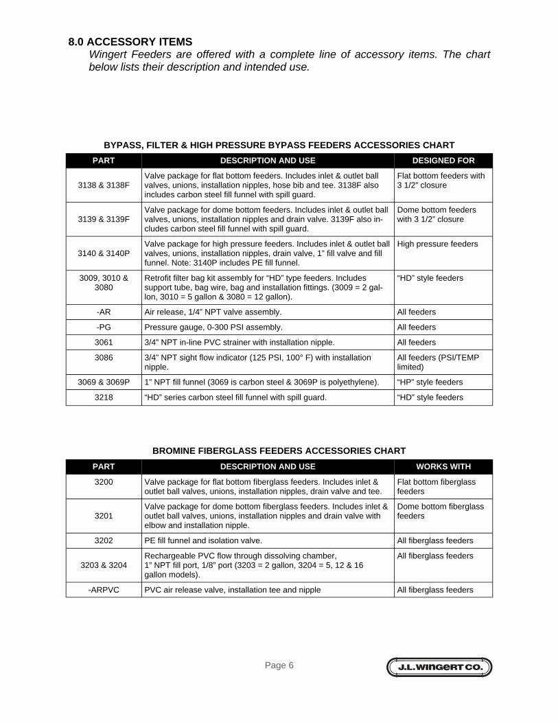
8.0 ACCESSORY ITEMS Wingert Feeders are offered with a complete line of accessory items. The chart below lists their description and intended use.
PART DESCRIPTION AND USE DESIGNED FOR
3138 & 3138F
Valve package for flat bottom feeders. Includes inlet & outlet ball valves, unions, installation nipples, hose bib and tee. 3138F also includes carbon steel fill funnel with spill guard.
Flat bottom feeders with 3 1/2” closure
3139 & 3139F
Valve package for dome bottom feeders. Includes inlet & outlet ball valves, unions, installation nipples and drain valve. 3139F also in-cludes carbon steel fill funnel with spill guard.
Dome bottom feeders with 3 1/2” closure
3140 & 3140P
Valve package for high pressure feeders. Includes inlet & outlet ball valves, unions, installation nipples, drain valve, 1” fill valve and fill funnel. Note: 3140P includes PE fill funnel.
High pressure feeders
3009, 3010 & 3080
Retrofit filter bag kit assembly for “HD” type feeders. Includes support tube, bag wire, bag and installation fittings. (3009 = 2 gal-lon, 3010 = 5 gallon & 3080 = 12 gallon).
“HD” style feeders
-AR Air release, 1/4” NPT valve assembly. All feeders
-PG Pressure gauge, 0-300 PSI assembly. All feeders
3061 3/4” NPT in-line PVC strainer with installation nipple. All feeders
3086 3/4” NPT sight flow indicator (125 PSI, 100° F) with installation nipple.
All feeders (PSI/TEMP limited)
3069 & 3069P 1” NPT fill funnel (3069 is carbon steel & 3069P is polyethylene). “HP” style feeders
3218 “HD” series carbon steel fill funnel with spill guard. “HD” style feeders
BYPASS, FILTER & HIGH PRESSURE BYPASS FEEDERS ACCESSORIES CHART
BROMINE FIBERGLASS FEEDERS ACCESSORIES CHART
PART DESCRIPTION AND USE WORKS WITH
3200 Valve package for flat bottom fiberglass feeders. Includes inlet & outlet ball valves, unions, installation nipples, drain valve and tee.
Flat bottom fiberglass feeders
3201
Valve package for dome bottom fiberglass feeders. Includes inlet & outlet ball valves, unions, installation nipples and drain valve with elbow and installation nipple.
Dome bottom fiberglass feeders
3202 PE fill funnel and isolation valve. All fiberglass feeders
3203 & 3204
Rechargeable PVC flow through dissolving chamber, 1” NPT fill port, 1/8” port (3203 = 2 gallon, 3204 = 5, 12 & 16 gallon models).
All fiberglass feeders
-ARPVC PVC air release valve, installation tee and nipple All fiberglass feeders

Page 7
9.0 MAINTENANCE When filling or inspecting a feeder, ensure that the vessel is not under pressure. Close isolation valves and open drain valve before opening fill port. Caution: Opening air release valve will release pressure along with the possibility of residual contents of vessel. Feeders generally need very little maintenance. Consult a water treatment specialist to schedule servicing or recharging of the system. It is most important to always purge trapped air when returning feeder to service. Filters should be maintained based on solids in system. Check frequently until schedule can be determined.
10.0 PARTS LISTING
CATEGORY PART DESCRIPTION
3071 3 1/2” - 1/4 turn cast closure with pressure plate and standard o-ring
CLOSURE 3072 200°F standard o-ring
3073 400°F optional o-ring
3083 Bag support wire assembly for 2 & 5 gallon filter bag kits
FILTER 3101 Bag support wire assembly for 12 gallon filter bag kits
BAG KITS 3084 Filter bag kit support tube assembly for 2 gallon models
3085 Filter bag kit support tube assembly for 5 & 12 gallon models
3128 Perforated basket assembly for 2 & 5 gallon models
FILTER 3129 Perforated basket assembly for 12 gallon models
FEEDERS 3131 Replacement 25 micron filter bag with ring for 2 & 5 gallon models
3132 Replacement 25 micron filter bag with ring for 12 gallon models
HIGH CAPACITY 3160 Perforated basket assembly for all models
FILTER FEEDERS 3131 Replacement 25 micron filter bag with ring for all models
PLEATED FILTER 3186 Hanger assembly for all models
FEEDERS 3187 Pleated 20 micron filter for all models
3141 3/4” NPT brass ball valve and installation nipple
VALVE 3142 1” NPT brass ball valve and installation nipple
PACKAGE 3063 Hose bib, 3/4” NPT 200PSI brass with installation nipple
3079 Union, 3/4” NPT with installation nipple
FIBERGLASS 3205 2 1/2” CPVC closure with o-ring
FEEDERS 3206 4” CPVC closure with o-ring
Note: Other parts available upon request. Please contact customer service for information and availability.
P.O. Box 6207 • Garden Grove, CA 92846-6207 / 11800 Monarch St. • Garden Grove, CA 92841-2113 • Phone (714) 379-5519 • Fax (714) 379-5549 Northern California Region • Phone (510) 487-5310 • Southwest Region • Phone (602) 470-1015 • Email: [email protected]
www.jlwingert.com