BY ORDER OF THE COMMANDER EGLIN AIR FORCE BASE …
189
BY ORDER OF THE COMMANDER EGLIN AIR FORCE BASE EGLIN AIR FORCE BASE INSTRUCTION 13-204 22 DECEMBER 2020 Nuclear, Space, Missile, Command and Control AIR OPERATIONS COMPLIANCE WITH THIS PUBLICATION IS MANDATORY ACCESSIBILITY: Publications and forms are available on the e-Publishing website at www.e-Publishing.af.mil for downloading or ordering RELEASABILITY: There are no releasability restrictions on this publication OPR: 96 OSS/OSA Supersedes: EGLINAFBI 11-201; 13 June 2016 Certified by: 96 OG/CC (Col Douglas O. Creviston) Pages: 189 This instruction implements and extends the guidance of Air Force Instruction (AFI) 13-204, Volume 3, Airfield Operations Procedures and Programs, 1 September 2010 and AFPD 13-2, Air Traffic Control, Airspace, Airfield, and Range Management. This Directive sets forth policies regarding Eglin AFB and the Eglin Range Complex activities of Air Force civilian and military personnel, including the Air Force Reserve, Air National Guard, and Civil Air Patrol. It establishes procedures for safe and efficient airfield operations. It applies to all flying activities within Eglin Air Force Base delegated airspace to include its auxiliary airfields and all test areas in the Eglin Reservation. It also promotes the safe expenditure of ordnance and use of lasers during all test missions, weapons employment training missions, aerial demonstrations, and aircraft exercises in the 96th Test Wing (96 TW) test area complex. It supplements AFI 32- 1043, Managing, Operating, and Maintaining Aircraft Arresting Systems, and all applicable Federal Aviation Administration Handbooks/Joint Orders, and Department of Defense Flight Information Publications. Refer recommended changes and questions about this publication to the Office of Primary Responsibility (OPR) using the AF Form 847, Recommendation for Change of Publication; route AF Forms 847 from the field through the appropriate functional chain of command. Ensure that all records created as a result of processes prescribed in this publication are maintained IAW Air Force Manual (AFMAN) 33-363, Management of Records, and disposed of IAW Air Force Records Information Management System (AFRIMS) Records Disposition Schedule (RDS).
Transcript of BY ORDER OF THE COMMANDER EGLIN AIR FORCE BASE …
BY ORDER OF THE COMMANDER
EGLIN AIR FORCE BASE
EGLIN AIR FORCE BASE
INSTRUCTION 13-204
22 DECEMBER 2020
Nuclear, Space, Missile, Command and
Control
AIR OPERATIONS
COMPLIANCE WITH THIS PUBLICATION IS MANDATORY
ACCESSIBILITY: Publications and forms are available on the e-Publishing website at
www.e-Publishing.af.mil for downloading or ordering
RELEASABILITY: There are no releasability restrictions on this publication
OPR: 96 OSS/OSA
Supersedes: EGLINAFBI 11-201;
13 June 2016
Certified by: 96 OG/CC
(Col Douglas O. Creviston)
Pages: 189
This instruction implements and extends the guidance of Air Force Instruction (AFI) 13-204,
Volume 3, Airfield Operations Procedures and Programs, 1 September 2010 and AFPD 13-2,
Air Traffic Control, Airspace, Airfield, and Range Management. This Directive sets forth
policies regarding Eglin AFB and the Eglin Range Complex activities of Air Force civilian and
military personnel, including the Air Force Reserve, Air National Guard, and Civil Air Patrol. It
establishes procedures for safe and efficient airfield operations. It applies to all flying activities
within Eglin Air Force Base delegated airspace to include its auxiliary airfields and all test areas
in the Eglin Reservation. It also promotes the safe expenditure of ordnance and use of lasers
during all test missions, weapons employment training missions, aerial demonstrations, and
aircraft exercises in the 96th Test Wing (96 TW) test area complex. It supplements AFI 32-
1043, Managing, Operating, and Maintaining Aircraft Arresting Systems, and all applicable
Federal Aviation Administration Handbooks/Joint Orders, and Department of Defense Flight
Information Publications. Refer recommended changes and questions about this publication to
the Office of Primary Responsibility (OPR) using the AF Form 847, Recommendation for
Change of Publication; route AF Forms 847 from the field through the appropriate functional
chain of command. Ensure that all records created as a result of processes prescribed in this
publication are maintained IAW Air Force Manual (AFMAN) 33-363, Management of Records,
and disposed of IAW Air Force Records Information Management System (AFRIMS) Records
Disposition Schedule (RDS).
2 EGLINAFBI13-204 22 DECEMBER 2020
SUMMARY OF CHANGES
This document has been substantially revised and must be completely reviewed. An
accompanying change document is available upon request to the OPR.
Chapter 1—GENERAL INFORMATION 12
1.1. Scope. ....................................................................................................................... 12
1.2. Administration. ........................................................................................................ 12
1.3. Flight Information Publications (FLIP) Accounts. .................................................. 13
1.4. Airfield Operations Board. ...................................................................................... 13
Table 1.1. AOB Membership. ................................................................................................... 13
Table 1.2. Annual Review Items. .............................................................................................. 14
1.5. Bird Wildlife Aircraft Strike Hazard (BASH) Alerting Procedures. ....................... 14
1.6. Local Frequency Channelization. Table 1.3. .......................................................... 16
Table 1.3. Common Frequencies/Local Channels. ................................................................... 16
Table 1.4. Additional Local Area Frequencies. ........................................................................ 17
1.7. Local Aircraft Operational Priorities. ...................................................................... 17
1.8. Airfield Quiet Period Request. ................................................................................. 18
1.9. Procedures for Eglin AFB Assigned Off-Station Aircraft. ...................................... 18
1.10. Supervisor of Flying (SOF). .................................................................................... 19
Chapter 2—LOCAL AIRSPACE/FLYING AREAS/TEST AREAS 20
2.1. EAFB Reservation. .................................................................................................. 20
2.2. Local Flying Area. ................................................................................................... 20
2.3. Restricted Areas. ...................................................................................................... 20
2.4. Military Operations Areas (MOA). .......................................................................... 20
2.5. 14 CFR PART 93 Airspace...................................................................................... 21
2.6. Warning Areas. ........................................................................................................ 22
2.7. Military Training Routes (MTR). ............................................................................ 22
2.8. Controlled Firing Areas (CFA). ............................................................................... 22
2.9. Class D/E Surface Areas. ......................................................................................... 23
EGLINAFBI13-204 22 DECEMBER 2020 3
2.10. Eglin/Duke Tower Transition Area (TTA). ............................................................. 24
2.11. Water Hoist Helicopter Training Area. .................................................................... 24
2.12. Aero Club/General Aviation Training Areas: .......................................................... 24
2.13. Hurlburt “H” Alignment Area. ................................................................................ 25
2.14. Duke Field Alignment Area. .................................................................................... 25
2.15. Eglin Water Test Area (EWTA). ............................................................................. 25
2.16. Eglin “E” Area. ........................................................................................................ 25
2.17. Air Traffic Control Assigned Airspace (ATCAA). ................................................. 25
2.18. Other Airports and Facilities. ................................................................................... 26
Chapter 3—RADAR AND MISSION PROCEDURES 27
3.1. Eglin Radar Control Facility (ERCF). ..................................................................... 27
3.2. Enroute Procedures. ................................................................................................. 27
3.3. Special Use Airspace (SUA) Procedures. ................................................................ 27
3.4. Recovery Procedures. .............................................................................................. 31
Chapter 4—EAFB OPERATIONS AND PROCEDURES 35
4.1. EGLINAFB (VPS) Operating Hours. ...................................................................... 35
4.2. Prior Permission Required (PPR). ........................................................................... 35
4.3. Civil Aircraft Landing Permit (CALP). ................................................................... 35
4.4. Transient Alert (TA). ............................................................................................... 35
4.5. Runways and Taxiways. .......................................................................................... 35
4.6. Restricted/Classified Areas. ..................................................................................... 37
4.7. Aircraft Parking Plan. .............................................................................................. 37
4.8. Aircraft Special Operation Areas/Ramps: ............................................................... 37
4.9. Ground Navigational Aid (NAVAID) Checkpoints. ............................................... 38
4.10. Navigational Aids (NAVAIDs) and Air Traffic Control and Landing Systems
(ATCALS). .............................................................................................................. 38
4.11. Permanently Closed/Unusable Portions of the Airfield. .......................................... 39
4.12. Airfield Lighting. ..................................................................................................... 39
4.13. ATIS, Weather Dissemination and Coordination Procedures.................................. 39
4 EGLINAFBI13-204 22 DECEMBER 2020
4.14. Active Runway Selection and Change Procedures. ................................................. 39
4.15. Runway Surface Condition (RSC) and/or Runway Condition Reading (RCR)
Values. ..................................................................................................................... 41
4.16. Aircraft Arresting Systems. ..................................................................................... 41
Table 4.1. Eglin Aircraft Arresting System Locations. ............................................................. 41
4.17. NOTAM Procedures. ............................................................................................... 42
4.18. Airfield Maintenance. .............................................................................................. 42
4.19. Airfield Tobacco Use Policy. ................................................................................... 42
4.20. Photograph/Video on the Airfield and Ranges. ....................................................... 42
Table 4.2. Photograph/Video Responsible Agencies. ............................................................... 43
4.21. Wear of Hats. ........................................................................................................... 44
4.22. Scheduling and Flight Plan Procedures. .................................................................. 44
4.23. Controlled Movement Area (CMA). ........................................................................ 45
4.24. Precision Approach Critical Area. ........................................................................... 46
4.25. Engine Test/Run-Up Areas and Procedures. ........................................................... 46
4.26. Procedures for Suspending, Opening, and/or Closing the Runway. ........................ 47
4.27. Airfield Inspections/Checks. .................................................................................... 47
4.28. Aircraft Towing Procedures. .................................................................................... 47
4.29. Aeromedical Aircraft Arrival Procedures. ............................................................... 47
4.30. Local Control Points. ............................................................................................... 47
Table 4.3. Local Control Points. ............................................................................................... 48
Table 4.4. Eglin VFR Reporting/Holding Points. ..................................................................... 49
4.31. Taxi Procedures. ...................................................................................................... 49
4.32. Reduced Same Runway Separation (RSRS). ........................................................... 50
Table 4.5. RSRS Standards. ...................................................................................................... 50
4.33. General Departure Procedures. ................................................................................ 51
Table 4.6. EAFB Intersection Departure Distance Remaining. ................................................ 52
4.34. General Recovery Procedures. ................................................................................. 53
Table 4.7. VFR Pattern Matrix. ................................................................................................ 57
EGLINAFBI13-204 22 DECEMBER 2020 5
4.35. Simulated Flameout (SFO) and Precautionary Flameout (PFO) Approaches. ........ 62
4.36. Rectangular Pattern. ................................................................................................. 66
4.37. Noise Abatement Procedures. .................................................................................. 67
Table 4.8. Minimum Noise Abatement Altitudes. .................................................................... 67
4.38. Areas of Potential Conflict....................................................................................... 68
4.39. Hurlburt Field Patterns. ............................................................................................ 68
4.40. IFR Procedures. ....................................................................................................... 68
4.41. Restricted Low Approach. ....................................................................................... 69
4.42. Aero Club Procedures. ............................................................................................. 70
4.43. Helicopter/Tiltrotor Operations. .............................................................................. 71
Chapter 5—DUKE FIELD OPERATIONS AND PROCEDURES 74
5.1. EAFB/Auxiliary Field Three (Duke Field, KEGI) Operating Hours. ...................... 74
5.2. Transient Alert. ........................................................................................................ 74
5.3. Runway and Taxiways. ............................................................................................ 75
5.4. Restricted/Classified Areas on the Airfield. ............................................................ 75
5.5. Aircraft Parking Plan. .............................................................................................. 76
5.6. Aircraft Special Operation Areas/Aprons. ............................................................... 76
5.7. Airfield Hazards. ...................................................................................................... 80
5.8. NAVAIDs and ATCALS. ........................................................................................ 80
5.9. Permanently Closed/Unusable Portions of the Airfield. .......................................... 80
5.10. Airfield Lighting. ..................................................................................................... 80
5.11. ATIS, Weather Dissemination and Coordination Procedures.................................. 81
5.12. Active Runway Selection and Change Procedures. ................................................. 81
5.13. Runway Surface Condition (RSC) and/or Runway Condition Reading (RCR)
Values. ..................................................................................................................... 81
5.14. Aircraft Arresting Systems. ..................................................................................... 81
Table 5.1. Duke Field Aircraft Arresting System Locations. ................................................... 82
5.15. NOTAM Procedures. ............................................................................................... 82
5.16. Airfield Maintenance. .............................................................................................. 83
6 EGLINAFBI13-204 22 DECEMBER 2020
5.17. Airfield Tobacco Use Policy. ................................................................................... 83
5.18. Wear of Hats. ........................................................................................................... 83
5.19. Airfield Photography. .............................................................................................. 83
5.20. Scheduling and Flight Plan Procedures. .................................................................. 83
5.21. Controlled Movement Area (CMA). ........................................................................ 83
5.22. Precision Approach Critical Area. ........................................................................... 84
5.23. Engine Test/Run-Up Areas and Procedures. ........................................................... 84
5.24. Procedures for Suspending, Opening and/or Closing the Runway. ......................... 84
5.25. Airfield Inspections/Checks. .................................................................................... 84
5.26. Aircraft Towing Procedures. .................................................................................... 84
5.27. Aeromedical Aircraft Arrival Procedures. ............................................................... 84
5.28. Local Control Points. ............................................................................................... 84
5.29. Tower Visual Blind Spots. ....................................................................................... 84
5.30. Reduced Same Runway Separation (RSRS). ........................................................... 85
5.31. General Departure Procedures. ................................................................................ 85
Table 5.2. Duke Field Intersection Departure Distance Remaining. ........................................ 85
5.32. General Recovery Procedures. ................................................................................. 85
5.33. SFO and PFO Approaches. ...................................................................................... 88
5.34. Duke Field Random Steep Approach. ..................................................................... 91
5.35. Duke Field Random Shallow Approach. ................................................................. 92
5.36. VFR NVD Operations: ............................................................................................ 93
Chapter 6—EMERGENCY PROCEDURES 94
6.1. Daily Primary Crash Alarm System (PCAS) Phone Check. .................................... 94
6.2. Emergency Notification. .......................................................................................... 94
6.3. Arrival/Departures. .................................................................................................. 94
6.4. Eglin/Duke Field Discrete Emergency Frequency. .................................................. 94
6.5. In-Flight/Ground Emergency Responsibilities/Procedures. .................................... 94
6.6. Emergency Information. .......................................................................................... 95
6.7. Emergency Locator Transmitters (ELT) and Crash Position Indicators (CPI). ....... 96
EGLINAFBI13-204 22 DECEMBER 2020 7
6.8. Beacon Code 7700 Response on the Ground. .......................................................... 97
6.9. Runway Checks Following an Emergency. ............................................................. 97
6.10. Aircraft Arresting System Procedures. .................................................................... 97
6.11. Fuel Dumping. ......................................................................................................... 98
6.12. External Stores/In-Flight Aircraft Cargo Jettison Procedures. ................................ 98
6.13. MC-130 Refueling Hose Jettison Procedures. ......................................................... 98
6.14. Aircraft Abandonment/Controlled Bailout Procedures. ........................................... 98
6.15. Emergency Landing Gear Checks. .......................................................................... 99
6.16. Hot Brakes Parking Areas. ....................................................................................... 99
6.17. Hydrazine Leak Parking Areas. ............................................................................... 99
6.18. Alternate ATC Facility Procedures. ......................................................................... 100
6.19. Unauthorized Movement/Preventing/Resisting Aircraft Piracy/Hijacking. ............ 103
Chapter 7—RANGE EMERGENCY PROCEDURES 104
7.1. Inadvertent Release Procedures. .............................................................................. 104
7.2. Unintentional Release Procedures. .......................................................................... 104
7.3. Unexpended Ordnance Procedures. ......................................................................... 104
7.4. Hung/Jammed/Unsafe Gun Procedures. .................................................................. 104
7.5. Jettison Procedures. ................................................................................................. 107
7.6. Hung Ordnance General Procedures. ....................................................................... 107
Table 7.1. Munitions (Ordnance)/External Stores Categories for Developmental Weapons. .. 108
7.7. Hung Ordnance Notification Procedures. ................................................................ 109
Table 7.2. In-Flight Emergency (IFE) Crash Rescue Response. .............................................. 110
7.8. Hung Ordnance Recovery Procedures. .................................................................... 110
7.9. IFR Hung Ordnance Recovery Routes. ................................................................... 112
7.10. De-Arming Procedures. ........................................................................................... 112
7.11. Radio Failure Procedures with Ordnance. ............................................................... 113
7.12. Helicopter and AC-130 Gunship Weapon System Malfunctions. ........................... 113
7.13. Crash Procedures. .................................................................................................... 113
7.14. RCO Procedures during Emergencies. .................................................................... 114
8 EGLINAFBI13-204 22 DECEMBER 2020
Chapter 8—TEST MISSION PROCEDURES 115
8.1. Test Area Scheduling. .............................................................................................. 115
8.2. Test Area Control. .................................................................................................... 115
Table 8.1. Test Area Control Authority. ................................................................................... 116
8.3. Test Area Operations Responsibilities. .................................................................... 116
8.4. Departure Procedures. .............................................................................................. 117
8.5. Test Area Procedures for Ordnance Delivery Missions. .......................................... 117
Chapter 9—RANGE OPERATIONS 119
9.1. Purpose. ................................................................................................................... 119
9.2. Policies. .................................................................................................................... 119
9.3. Test Area Safety. ...................................................................................................... 119
9.4. General Test Area Procedures. ................................................................................ 119
9.5. Test Area Entry. ....................................................................................................... 119
9.6. Test Area C-62 Procedures. ..................................................................................... 120
Table 9.1. Test Area C-62 Delivery Headings and Pattern Directions. .................................... 120
9.7. Test Area C-52N Procedures. .................................................................................. 121
9.8. Test Area B-6 (Eglin Field 6, Army Ranger Camp, Camp Rudder). ....................... 123
9.9. Rejoins/Departures. .................................................................................................. 123
9.10. RCO Procedures. ..................................................................................................... 123
Table 9.2. AFI 13-212 Items. .................................................................................................... 123
Chapter 10—OPERATIONAL PROCEDURES FOR THE EMPLOYMENT OF
ELECTRONIC PROTECTIVE MEASURES (EPM), CHAFF, FLARES,
AND LASERS 127
10.1. Purpose. ................................................................................................................... 127
10.2. Responsibilities. ....................................................................................................... 127
10.3. Authorized Systems. ................................................................................................ 128
10.4. Scheduling. .............................................................................................................. 128
10.5. Departure Procedures. .............................................................................................. 128
10.6. Flare Employment Procedures. ................................................................................ 128
EGLINAFBI13-204 22 DECEMBER 2020 9
10.7. Chaff Employment Procedures: ............................................................................... 128
10.8. EPM Employment Procedures: ................................................................................ 129
10.9. Recoveries. ............................................................................................................... 129
10.10. Airborne Laser Operations. ...................................................................................... 129
Table 10.1. Laser Targets. ........................................................................................................... 130
Chapter 11—SUPERSONIC OPERATIONS 132
11.1. Supersonic Operations. ............................................................................................ 132
Chapter 12—REMOTELY PILOTED AIRCRAFT (RPA) 133
12.1. General. .................................................................................................................... 133
12.2. Airfields for RPA. .................................................................................................... 133
12.3. Airspace for SUAS. ................................................................................................. 134
12.4. Emergency Procedures. ........................................................................................... 135
12.5. Weapon Employment. ............................................................................................. 136
Attachment 1—GLOSSARY OF REFERENCES AND SUPPORTING INFORMATION 137
Attachment 2—EGLIN AFB AIRFIELD DIAGRAM 144
Attachment 3—EGLIN AFB CONTROLLED MOVEMENT AREA DIAGRAM 145
Attachment 4—EGLIN AFB HOT PIT/LOLA PROCEDURES 146
Attachment 5—EGLIN AFB VFR OVERHEAD PATTERNS 147
Attachment 6—EGLIN AFB VFR RECTANGULAR PATTERNS 148
Attachment 7—EGLIN VFR TRAFFIC PATTERNS RUNWAYS 12/19 ACTIVE 149
Attachment 8—EGLIN VFR TRAFFIC PATTERNS RUNWAYS 1/30 ACTIVE 150
Attachment 9—RUNWAY 12/30 SIMULATED FLAMEOUT (SFO) PATTERN 151
Attachment 10—OVERHEAD SFO AND STRAIGHT-IN SFO PATTERNS 152
Attachment 11—RWY 12/30 RANDOM ENTRY SIMULATED FLAMEOUT PATTERN
(RESFO) PROCEDURES 153
Attachment 12—VFR TOWER TO TOWER PROCEDURES – SOUTH FLOW 154
Attachment 13—VFR TOWER TO TOWER PROCEDURES – NORTH FLOW 155
Attachment 14—VFR TOWER TO TOWER PROCEDURES – MIXED FLOW VPS RWY
1/30 &EGI RWY 18 156
10 EGLINAFBI13-204 22 DECEMBER 2020
Attachment 15—VFR TOWER TO TOWER PROCEDURES – MIXED FLOW VPS RWY
12/19 & EGI RWY 36 157
Attachment 16—EGLIN AFB RADAR RECTANGULAR PATTERNS 158
Attachment 17—DDUNE RECOVERY 159
Attachment 18—WHISKEY HOTEL RECOVERY 161
Attachment 19—NORTH FLOW RECOVERY 162
Attachment 20—DUKE FIELD AIRFIELD DIAGRAM 164
Attachment 21—DUKE FIELD CONTROLLED MOVEMENT AREA DIAGRAM 165
Attachment 22—DUKE FIELD SOUTH OPERATIONS 166
Attachment 23—DUKE FIELD NORTH OPERTIONS 167
Attachment 24—DUKE FIELD STOVL PADS SOUTH OPERATIONS 168
Attachment 25—DUKE FIELD STOVL PADS NORTH OPERATIONS 169
Attachment 26—DUKE FIELD VFR RETANGULAR PATTERNS 170
Attachment 27—DUKE FIELD VFR OVERHEAD PATTERNS 171
Attachment 28—DUKE FIELD RANDOM SHALLOW APPROACH 172
Attachment 29—DUKE FIELD RANDOM STEEP APPROACH 173
Attachment 30—DUKE FIELD EQUIPMENT DROP ZONE PROCEDURES 174
Attachment 31—DUKE FIELD HELICOPTER VFR EAST TRAINING AREA (VETA) 175
Attachment 32—DUKE FIELD, HURLBURT FIELD, DESTIN, AND CRESTVIEW
RADAR RECTANGULAR PATTERNS 176
Attachment 33—HURLBURT FIELD VFR RECTANGULAR PATTERNS 177
Attachment 34—HURLBURT FIELD VFR OVERHEAD PATTERNS 178
Attachment 35—EGLIN LOCAL FLYING AREA 179
Attachment 36—CLASS DELTA AND ECHO SURFACE AREAS, MOAS, AND
RESTRICTED AREAS 180
Attachment 37—FAR PART 93 AIRSPACE (NORTH/SOUTH – EAST/WEST
CORRIDORS) 181
Attachment 38—LOCAL CONTROL POINTS 182
Attachment 39—EGLIN WATER TEST AREAS 183
Attachment 40—W-151 AND W-470 SUBDIVISIONS 184
EGLINAFBI13-204 22 DECEMBER 2020 11
Attachment 41—W-470 185
Attachment 42—WARNING AIRSPACE BREEDING/THUNDER/LIGHTNING AREA
DIAGRAM 186
Attachment 43—AERO CLUB TRAINING AREAS AND SANTA ROSA ISLAND CFA 187
Attachment 44—EMERGENCY JETTISON/BAILOUT AREAS 188
Attachment 45—NOISE ABATEMENT AND SAFETY MINIMUM ALTITUDES 189
12 EGLINAFBI13-204 22 DECEMBER 2020
Chapter 1
GENERAL INFORMATION
1.1. Scope. The rules and instructions herein are issued to promote the safe, orderly, and
expeditious movement of air traffic within Eglin’s Air Traffic Control (ATC) airspace and the
safe expenditure of ordnance and use of lasers during all test missions, weapons employment
training missions, aerial demonstrations, and aircraft exercises in the Eglin Range Complex.
Pilots, air traffic controllers, and airfield operations professionals are expected to exercise their
best judgment for real-time decision making and contact the OPR for guidance not covered in
this instruction. Commanders of assigned, associate, and deployed units will ensure their
personnel understand and comply with applicable chapters of this instruction, the Safety
Appendix to the test directive (TD), memorandums of agreement, letters of agreement (LOA),
appropriate command directives, and aircraft technical orders, for planning and executing of their
individual test program or weapons employment training program.
1.2. Administration. The Commander, 96th Test Wing (96 TW/CC) is responsible for this
instruction. The 96 TW/CC will ensure all units visiting EAFB to conduct missions on the Eglin
Range complex review and abide by this instruction. The 96 TW/CC has delegated waiver
approval authority to this instruction for special mission requirements to the 96 OG/CC, except
when higher waiver approval authority is dictated by AFI. All procedural changes affecting air
traffic control must be approved by AFMC/A3OO before implementation. All airfield/airspace
criteria waiver requests will be accomplished IAW AFI 13-204V3, Airfield Operations
Procedures and Programs, using AF IMT 4058, Airfield Operations Policy Waiver. Suggested
changes to this instruction and all waiver requests shall be sent to 96 OSS/OSA, 505 N.
Barrancas Ave, Bldg 104, Ste 209D, Eglin AFB FL 32542-6818, or by email to
[email protected] for review and coordination.
1.2.1. The 96 OG/OGV is responsible for establishing a Flight Crew Information File (FCIF)
process to ensure all affected units receive timely updates to this instruction. Any 96
OG/OGV FCIF issued that affects topics within EAFBI 13-204, operations at EAFB, or the
EAFB Reservation will be distributed to 96 OSS, 33 OG/OGV, 325 OG/OGV, 492
SOG/OGV, 85 TES/DOV, 919 SOG/OGV, 1 SOG/OGV, Eglin Aero Club Manager, and
Destin-Fort Walton Beach Airport Manager.
1.2.2. A list of references, terms, abbreviations, and acronyms to this instruction is included
in Attachment 1.
1.2.3. Within this instruction, visibility distances are measured in statute miles (SM) and all
other distances are measured in nautical miles (NM) unless otherwise identified.
1.2.4. All references to AFI 13-204 within this instruction shall read AFMAN 13-204 once
AFMAN 13-204 is published.
EGLINAFBI13-204 22 DECEMBER 2020 13
1.3. Flight Information Publications (FLIP) Accounts. Eglin Airfield Management
Operations (AMOPS) manages the 96 TW FLIP accounts for all assigned units on Eglin and
Duke Field. Send all suggested nonprocedural FLIP changes to 96 OSS/OSAM, 601 N.
Choctawhatchee Ave, Ste 80, Eglin AFB FL 32542-5718 or call COMM: (850) 882-2614/ DSN:
872-2614. Send all procedural FLIP changes to 96 OSS/OSA (TERPS), 505 N. Barrancas Ave,
Ste 209J, Eglin AFB FL 32542.
1.4. Airfield Operations Board. IAW AFI 13-204V3, the 96 TW/CV has delegated chair
responsibility to the 96 OG/CC for the Eglin AFB Airfield Operations Board (AOB). The AOB
will meet on a quarterly basis, IAW AFI 13-204V3, para 4.2. New agenda items shall be
provided to the Airfield Operations Flight (96 OSS/OSA) no later than 15 working days prior to
the board meeting to ensure they will be included for discussion. The Eglin Airfield Operations
Flight Commander (AOF/CC) will distribute a proposed agenda at least 10 working days prior to
each board meeting. Each subject matter Office of Primary Responsibility (OPR) shall be
prepared to brief the status of each open agenda item.
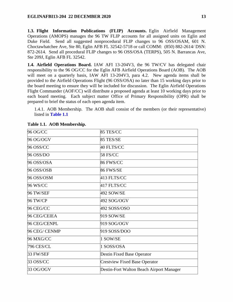
1.4.1. AOB Membership. The AOB shall consist of the members (or their representative)
listed in Table 1.1
Table 1.1. AOB Membership.
96 OG/CC 85 TES/CC
96 OG/OGV 85 TES/SE
96 OSS/CC 40 FLTS/CC
96 OSS/DO 58 FS/CC
96 OSS/OSA 86 FWS/CC
96 OSS/OSB 86 FWS/SE
96 OSS/OSM 413 FLTS/CC
96 WS/CC 417 FLTS/CC
96 TW/SEF 492 SOW/SE
96 TW/CP 492 SOG/OGV
96 CEG/CC 492 SOSS/OSO
96 CEG/CEIEA 919 SOW/SE
96 CEG/CENPL 919 SOG/OGV
96 CEG/ CENMP 919 SOSS/DOO
96 MXG/CC 1 SOW/SE
796 CES/CL 1 SOSS/OSA
33 FW/SEF Destin Fixed Base Operator
33 OSS/CC Crestview Fixed Base Operator
33 OG/OGV Destin-Fort Walton Beach Airport Manager
14 EGLINAFBI13-204 22 DECEMBER 2020
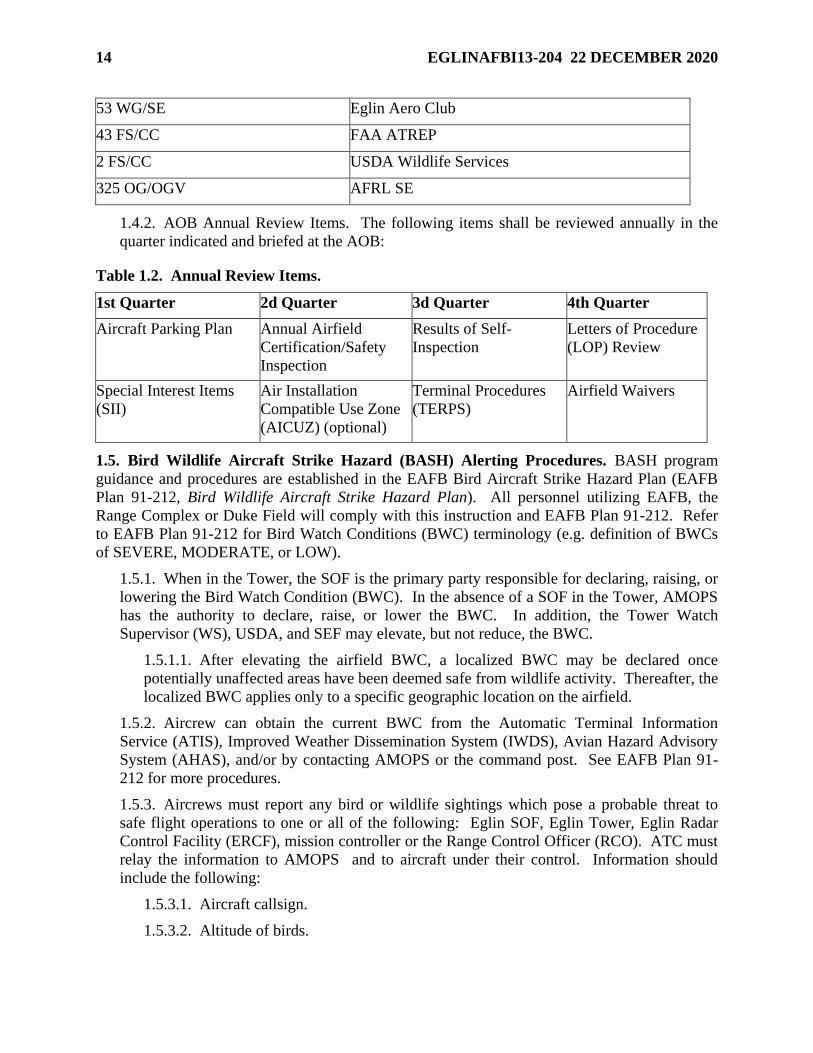
53 WG/SE Eglin Aero Club
43 FS/CC FAA ATREP
2 FS/CC USDA Wildlife Services
325 OG/OGV AFRL SE
1.4.2. AOB Annual Review Items. The following items shall be reviewed annually in the
quarter indicated and briefed at the AOB:
Table 1.2. Annual Review Items.
1st Quarter 2d Quarter 3d Quarter 4th Quarter
Aircraft Parking Plan Annual Airfield
Certification/Safety
Inspection
Results of Self-
Inspection
Letters of Procedure
(LOP) Review
Special Interest Items
(SII)
Air Installation
Compatible Use Zone
(AICUZ) (optional)
Terminal Procedures
(TERPS)
Airfield Waivers
1.5. Bird Wildlife Aircraft Strike Hazard (BASH) Alerting Procedures. BASH program
guidance and procedures are established in the EAFB Bird Aircraft Strike Hazard Plan (EAFB
Plan 91-212, Bird Wildlife Aircraft Strike Hazard Plan). All personnel utilizing EAFB, the
Range Complex or Duke Field will comply with this instruction and EAFB Plan 91-212. Refer
to EAFB Plan 91-212 for Bird Watch Conditions (BWC) terminology (e.g. definition of BWCs
of SEVERE, MODERATE, or LOW).
1.5.1. When in the Tower, the SOF is the primary party responsible for declaring, raising, or
lowering the Bird Watch Condition (BWC). In the absence of a SOF in the Tower, AMOPS
has the authority to declare, raise, or lower the BWC. In addition, the Tower Watch
Supervisor (WS), USDA, and SEF may elevate, but not reduce, the BWC.
1.5.1.1. After elevating the airfield BWC, a localized BWC may be declared once
potentially unaffected areas have been deemed safe from wildlife activity. Thereafter, the
localized BWC applies only to a specific geographic location on the airfield.
1.5.2. Aircrew can obtain the current BWC from the Automatic Terminal Information
Service (ATIS), Improved Weather Dissemination System (IWDS), Avian Hazard Advisory
System (AHAS), and/or by contacting AMOPS or the command post. See EAFB Plan 91-
212 for more procedures.
1.5.3. Aircrews must report any bird or wildlife sightings which pose a probable threat to
safe flight operations to one or all of the following: Eglin SOF, Eglin Tower, Eglin Radar
Control Facility (ERCF), mission controller or the Range Control Officer (RCO). ATC must
relay the information to AMOPS and to aircraft under their control. Information should
include the following:
1.5.3.1. Aircraft callsign.
1.5.3.2. Altitude of birds.
EGLINAFBI13-204 22 DECEMBER 2020 15
1.5.3.3. Approximate number of birds.
1.5.3.4. Type of birds, if known.
1.5.3.5. Location/direction of flight or roost.
1.5.3.6. Local time of sighting.
1.5.4. The following will be used to implement unit operational procedures.
1.5.4.1. BWC/Range Complex SEVERE. Operations in BWC SEVERE will only be
conducted with the flying unit’s OG/CC approval.
1.5.4.1.1. Landings. Only one approach to a full-stop landing is permitted.
1.5.4.1.2. Takeoffs. Takeoffs are prohibited without the flying unit’s OG/CC or
higher approval. If approved, no formation takeoffs are permitted.
1.5.4.1.3. Pattern. Aircraft will hold (fuel permitting) until the hazards no longer
exist. The SOF will consider closing the overhead pattern if that will minimize the
risk due to observed bird activity.
1.5.4.1.4. Units should consider delaying departures, arrivals and/or diverting
aircraft. The SOF and Tower Watch Supervisor may consider closing the VFR
pattern, as well as changing or suspending a runway with inputs from the Airfield
Manager. If the Eglin SOF in the Tower (or AM in the SOF’s absence) determines
the hazard is confined to a specific location that would allow safe operations to the
adjacent runway, the SOF may continue operations to the hazard free runway.
Supervisors and aircrews must thoroughly evaluate mission needs before conducting
operations in areas under BWC SEVERE. OG/CCs should consider prohibiting
takeoffs and limiting approaches to a full stop landing when under BWC SEVERE.
1.5.4.1.5. If the BWC is declared SEVERE in the range complex, the RCO will
identify a specific area and altitude to ensure the area is avoided by all aircrew
utilizing the range.
1.5.4.2. BWC/Range Complex MODERATE.
1.5.4.2.1. Traffic patterns shall be limited to the minimum required to accomplish
training requirements. OG/CCs should consider limiting takeoffs and landing to the
minimum necessary to fulfill mission requirements. OG/CCs should also consider
restricting close formation in the traffic pattern. Supervisors and aircrews shall
thoroughly evaluate mission requirements utilizing all available risk mitigation
methods and tools before conducting flight operations in areas under Bird Watch
Condition MODERATE. Pilots will be particularly cognizant of bird activity when
on final and will avoid low, flat approaches.
1.5.4.2.2. If BWC MODERATE is declared in the Eglin Range Complex, flight leads
will change event order or amend altitudes to minimize the hazard.
1.5.4.3. BWC/Range Complex LOW.
16 EGLINAFBI13-204 22 DECEMBER 2020
1.5.5. All personnel discovering a bird strike will initiate AF Form 853, Air Force Wildlife
Strike Report, or equivalent and notify the appropriate Maintenance Operations Control
Center (MOCC) or AMOPS for transient aircraft. The MOCC will notify AMOPS, 96th Test
Wing Flight Safety (96 TW/SEF), and Quality Assurance. More guidance is found in EAFB
Plan 91-212.
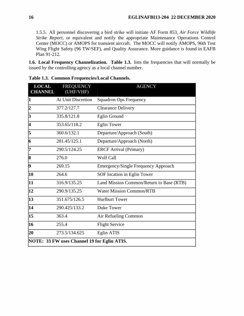
1.6. Local Frequency Channelization. Table 1.3. lists the frequencies that will normally be
issued by the controlling agency as a local channel number.
Table 1.3. Common Frequencies/Local Channels.
LOCAL
CHANNEL
FREQUENCY
(UHF/VHF)
AGENCY
1 At Unit Discretion Squadron Ops Frequency
2 377.2/127.7 Clearance Delivery
3 335.8/121.8 Eglin Ground
4 353.65/118.2 Eglin Tower
5 360.6/132.1 Departure/Approach (South)
6 281.45/125.1 Departure/Approach (North)
7 290.5/124.25 ERCF Arrival (Primary)
8 276.0 Wolf Call
9 269.15 Emergency/Single Frequency Approach
10 264.6 SOF location in Eglin Tower
11 316.9/135.25 Land Mission Common/Return to Base (RTB)
12 290.9/135.25 Water Mission Common/RTB
13 351.675/126.5 Hurlburt Tower
14 290.425/133.2 Duke Tower
15 363.4 Air Refueling Common
16 255.4 Flight Service
20 273.5/134.625 Eglin ATIS
NOTE: 33 FW uses Channel 19 for Eglin ATIS.
EGLINAFBI13-204 22 DECEMBER 2020 17
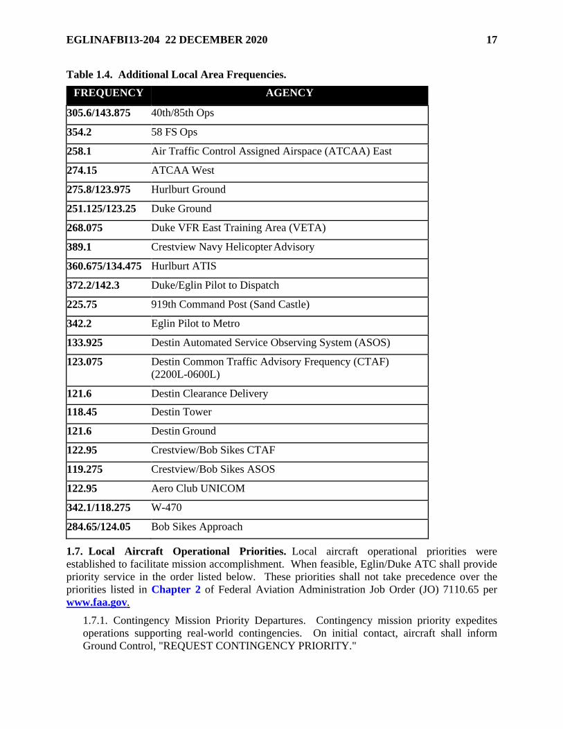
Table 1.4. Additional Local Area Frequencies.
FREQUENCY AGENCY
305.6/143.875 40th/85th Ops
354.2 58 FS Ops
258.1 Air Traffic Control Assigned Airspace (ATCAA) East
274.15 ATCAA West
275.8/123.975 Hurlburt Ground
251.125/123.25 Duke Ground
268.075 Duke VFR East Training Area (VETA)
389.1 Crestview Navy Helicopter Advisory
360.675/134.475 Hurlburt ATIS
372.2/142.3 Duke/Eglin Pilot to Dispatch
225.75 919th Command Post (Sand Castle)
342.2 Eglin Pilot to Metro
133.925 Destin Automated Service Observing System (ASOS)
123.075 Destin Common Traffic Advisory Frequency (CTAF)
(2200L-0600L)
121.6 Destin Clearance Delivery
118.45 Destin Tower
121.6 Destin Ground
122.95 Crestview/Bob Sikes CTAF
119.275 Crestview/Bob Sikes ASOS
122.95 Aero Club UNICOM
342.1/118.275 W-470
284.65/124.05 Bob Sikes Approach
1.7. Local Aircraft Operational Priorities. Local aircraft operational priorities were
established to facilitate mission accomplishment. When feasible, Eglin/Duke ATC shall provide
priority service in the order listed below. These priorities shall not take precedence over the
priorities listed in Chapter 2 of Federal Aviation Administration Job Order (JO) 7110.65 per
www.faa.gov.
1.7.1. Contingency Mission Priority Departures. Contingency mission priority expedites
operations supporting real-world contingencies. On initial contact, aircraft shall inform
Ground Control, "REQUEST CONTINGENCY PRIORITY."
18 EGLINAFBI13-204 22 DECEMBER 2020
1.7.2. Test Mission Priority Departures. Test mission priority departures may be requested
to prevent loss of a test mission due to a departure delay. Prior to taxi, a test pilot requesting
priority should inform Ground Control, "REQUEST TEST PRIORITY DEPARTURE.”
1.7.3. Exercise Priority Departures. Any flight participating in an exercise involving precise
air refueling control times or air drop times over a target may request priority by informing
Ground Control on initial contact, "REQUEST EXERCISE CONTROLLED TAKEOFF
TIME AT (time)." This priority shall only be used when timing is critical. When possible,
operational units requiring exercise priority shall coordinate controlled takeoff times and/or
unusual requests with the Tower Chief Controller.
1.7.4. Star Priority. Identifies aircraft operated by general officers. The filing agency shall
notify AMOPS that star-priority procedures are desired for a specific flight. AMOPS shall
notify the ERCF and Tower that star-priority procedures are in effect for (callsign). Star-
priority aircraft will be given expeditious handling whenever possible.
1.7.5. Distinguished Visitor (DV) Support Flights. The pilot must inform the controlling
agency that the flight is a DV support flight. The pilot of an Air Combat Command (ACC)
DV support flight may only declare priority when the DV is aboard the aircraft.
1.7.6. Government Aircraft Departures and Arrivals.
1.7.7. Air carrier/Aero Club Departures and Landings.
1.7.8. Practice Approaches.
1.8. Airfield Quiet Period Request. Quiet periods at Eglin and Duke Field shall be requested
IAW EAFBI 13-200, Eglin Range Mission Scheduling and Control.
1.9. Procedures for Eglin AFB Assigned Off-Station Aircraft. The Eglin Command Post is
responsible for maintaining accountability of all aircraft assigned to EAFB. To accomplish this
requirement, the following procedures will be followed.
1.9.1. Flying Squadron Responsibilities. All Eglin flying squadrons will provide a daily
flying schedule to the Eglin Command Post that will include weekends and holidays detailing
off- station itineraries (not to include individual sorties flown at the deployed location).
1.9.2. Aircrew Responsibilities. All Eglin aircrew will:
1.9.2.1. Notify the Eglin Command Post at COMM: (850) 883-4020/DSN: 875-4020 of
any deviations to their planned itinerary prior to takeoff.
1.9.2.2. Provide Command Post with the following information after each flight:
1.9.2.2.1. Actual departure and arrival times.
1.9.2.2.2. Total flying time.
1.9.2.2.3. Aircraft and aircrew status.
1.9.2.2.4. Phone number where they can be reached.
1.9.3. Command Post Responsibilities. Eglin Command Post will:
1.9.3.1. Confirm all landings and departures of assigned aircraft at all locations.
EGLINAFBI13-204 22 DECEMBER 2020 19
1.9.3.2. During normal duty hours, the command post will call the individual squadron
operations to pass along the information.
1.9.3.3. Implement appropriate checklist actions for all unconfirmed aircraft and submit
applicable reports in accordance with AFI 10-206, Operational Reporting.
1.10. Supervisor of Flying (SOF).
1.10.1. The SOF program and support provided by the Airfield Operations Flights will be
IAW AFMCI 11-201, Supervision of Flight Operations.
20 EGLINAFBI13-204 22 DECEMBER 2020
Chapter 2
LOCAL AIRSPACE/FLYING AREAS/TEST AREAS
2.1. EAFB Reservation. The EAFB reservation comprises all real property under jurisdiction
of the 96th Test Wing Commander (96 TW/CC). The boundaries, in general, may be described
as Choctawhatchee Bay and Santa Rosa Sound to the south; East Bay on the west; US Highway
331 on the east; and Yellow River and US Highway 90 to the north. The reservation includes
multiple tactical training areas, test areas, instrumented sites, EAFB, Hurlburt Field, Eglin
Auxiliary Field 3 (Duke Field), FL34 (Field 6), Auxiliary Field 1, Auxiliary Field 10 (Dillon
Field or NOLF Choctaw), Federal Aviation Administration (FAA) identifier NFJ. Specific
procedures for Choctaw Field are not prescribed in this regulation. Restricted airspace and 14
CFR Part 93, Special Air Traffic Rules, airspace overlays most of the reservation and there are
parts of the airspace over publicly owned property (See Attachment 36).
2.2. Local Flying Area. The local flying area consists of the National Airspace System (NAS),
Special Use Airspace (SUA), Airspace for Special Use (ASU), restricted areas, military
operations areas (MOA), 14 CFR Part 93 airspace, warning areas, controlled firing areas (CFA),
Class C, D, and E airspace, military training routes, and the uncharted Eglin Water Test Areas
(EWTA). This document will only address that airspace under the control of the 96th Test Wing.
Other SUA or ASU in the local area are available for mission execution and the attributes and
scheduling of each can be found in the DoD FLIPs, JO 7400.10, Special Use Airspace, and
Hurlburt Field Instruction (HFI) 11-201, Fixed and Rotary Wing Operations (See Attachments
35, 36, and 37).
2.3. Restricted Areas. Eglin’s SUA includes restricted areas R-2914A/B, R-2915A/B/C, R-
2917, R-2918, and R-2919A/B (See Attachment 36). The attributes of these areas are described
in the DoD FLIP and JO 7400.10. R-2917, utilized by United States Space Command
(USSPACECOM), is the hazard zone around Site C-6, Space Detection and Tracking System
(SPADATS). Site C-6 is the FPS-85 radar located within a 1 NM radius circle centered at
30º34’21”N/086º12’53”W which goes from surface to 5,000 ft Mean Sea Level (MSL). Due to
the nature and operation of SPADATS, R-2917 (surface to 5,000 ft MSL) is a no-fly zone for all
aircraft.
2.4. Military Operations Areas (MOA). EAFB SUA includes Eglin A East, A West, B, C, D,
E, F MOAs and Rose Hill MOA. Eglin A East, A West, B, C, D, and F MOAs are designated
for controlled egress and ingress for aircraft that wish to utilize the airspace over the EAFB
Reservation (See Attachment 36). This only applies to aircraft under the control of ERCF that
cannot be contained in the airspace over the EAFB Reservation due to a mission profile. These
MOAs shall be called up automatically by the ERCF for the requested altitudes if the profile for
the mission reflects utilization of that airspace. The attributes of these MOAs are described in
the DoD FLIP and JO 7400.10. NOTE: Due to high density airway traffic and flow constraints
north of the EAFB Reservation, normally only a block altitude of 2,000 ft may be scheduled
within the Eglin A, B, C and D MOAs at any given time. Excluding Eglin F MOA, any altitude
requested above 10,000 ft MSL will require Jacksonville Center approval. NOTE: The Eglin A
MOA is divided into an east and west section. The west section lies within Pensacola
Approach’s airspace and requires 15 minutes prior coordination by Eglin Approach for use. The
Navy Whiting Class C airspace is not part of Eglin A MOA.
EGLINAFBI13-204 22 DECEMBER 2020 21
2.4.1. Eglin D MOA. The Eglin D MOA is designated to provide airspace for the control of
aircraft transitioning from the Clear Springs Initial Point (IP) to Eglin Test Area C-62, within
R- 2914A, and from R-2914A to the IP. This MOA is designed to be used in conjunction
with Eglin C MOA. Use of the area is coordinated through the ERCF with a minimum of 15
minutes prior notification.
2.4.2. Eglin E MOA. Eglin E MOA overlies all of the Eglin restricted areas and the 14 CFR
Part 93 airspace. Use of Eglin E MOA is for those missions that are not classified as
hazardous. Upon request, ERCF may approve up to, but not including FL180. NOTE: This
is not to be confused with the Eglin E ATCAA as they are different airspaces.
2.4.3. Eglin F MOA. This MOA is designated for controlled penetration of the small
triangular area on the western boundary of R-2915B by mission aircraft under control of the
ERCF that cannot be contained in R-2915A/B/C because of the mission profile.
2.5. 14 CFR PART 93 Airspace. See Attachment 37. 14 CFR Part 93 Airspace is necessary
to simplify operating procedures, airspace assignment, and airspace use within the Valparaiso,
Florida, Terminal Area. 14 CFR Part 93 Airspace denotes special airport traffic patterns and
airport traffic areas. It also prescribes special air traffic rules for operating aircraft in those
traffic patterns, traffic areas, and in the vicinity of airports so designated as needing special
consideration. Unless otherwise authorized by ATC, each person operating an aircraft shall do
so in accordance with the special air traffic rules in 14 CFR Part 93 in addition to other
applicable rules in 14 CFR Part 91.
2.5.1. Eglin North-South Corridor. For dimensions of airspace within the boundaries of the
Eglin North-South Corridor, see 14 CFR Part 93 rules and the New Orleans Sectional. To
operate in the North-South Corridor, an aircraft must receive permission from the ERCF and
maintain two-way radio communications with the ERCF or an appropriate ATC facility.
2.5.1.1. This area is designed to facilitate aircraft movement to and from Eglin, Duke
Field, Hurlburt Field, Destin Airport, and other airports along the Florida Panhandle.
This area is also used in conjunction with the Eglin eastern range complex, Eglin western
range complex, or both range complexes to support special mission requirements.
2.5.1.2. The 96th TW has agreed to only close this corridor for the purpose of testing
long-range air-delivered weapons and missiles and to ensure that test missions requiring
the closing of this corridor do not delay air carrier arrival/departure flights more than 15
minutes. The Eglin North- South corridor IS NOT Special Use Airspace below FL180.
Therefore, the use of the corridor below FL 180 requires a NOTAM to be sent at least 12
hours prior to the planned mission. This Airspace does lie within the confines of the
Eglin E MOA but cannot be scheduled separately from the rest of the E MOA, as the E
MOA has no subdivisions. Both the FAA and the ERCF recognize the need to
occasionally schedule this airspace for missions below FL 180 and will make every
attempt to accommodate such requests.
2.5.1.2.1. The 7th SFG (A) Cantonment Area is in the Eglin North-South Corridor.
Olson Helicopter Landing Zone (HLZ) on the 7th SFG (A) Cantonment Area will not
be used for routine training and will be limited to Distinguished Visitor support.
22 EGLINAFBI13-204 22 DECEMBER 2020
2.5.1.2.2. Routine paradrop training will not be conducted in the Eglin North-South
Corridor. Directing paradrop aircraft for orbit and run-ins to a Drop Zone (DZ) in the
Eglin North-South Corridor significantly disrupts Eglin and Duke Class D airspace.
ATC must vector aircraft out of the Eglin North-South Corridor into restricted
airspace which has a corresponding impact to Eglin test and training missions. To
support the 7th SFG (A), paradrop operations will be limited to the 7th SFG (A)
Cantonment Area for high priority/special events only such as 7th SFG (A)/CC
Changes of Command, opening ceremonies, or memorial services. Limited event
rehearsal Eglin North- South Corridor paradrop missions will be scheduled. Eglin
North-South Corridor paradrop operations will be approved by the 96 OSS/CC.
2.5.2. Eglin East-West Corridor. For dimensions of airspace within these boundaries of the
Eglin East-West Corridor, see 14 CFR Part 93 rules and the New Orleans Sectional. The
corridor is divided into three sections to accommodate the different altitudes of R-2915C, R-
2919B, and R-2914B. The East-West Corridor facilitates access to airports in the Eglin-Fort
Walton Beach area and transition of aircraft from Pensacola to Panama City. The Eglin East-
West Corridor is not Special Use Airspace. It does lie within the confines of the Eglin E
MOA but cannot be scheduled separately from the rest of the E MOA, as the E MOA has no
subdivisions. The Santa Rosa Controlled Firing Area is also contained in this airspace and
rules for use are defined in Paragraph 2.8
2.6. Warning Areas. EAFB SUA includes warning areas W-151, W-168, and W-470 (See
Attachments 39, 40, and 41). The attributes of these areas are described in the DoD FLIP and
JO 7400.10. In DoD FLIP and the JO, W-151 and W-470 are subdivided into A through F areas.
The 96th Test Wing further subdivides these areas and the descriptions can be found in
Attachments 40, 41, and 42. The W-151 Shoreline Areas are a subdivision of W-151A and W-
151B and designated as W-151 S3, S4, S5, S6, and S7. The Shoreline airspace below 16,000’
shall only be scheduled as a last resort after coordination with 96 OSS/OSO.
2.7. Military Training Routes (MTR). There are two Visual Routes (VR) scheduled by the
96th Test Wing: VR1082 and VR1085. The description and attributes of MTRs can be found in
DoD FLIP AP/1B. Both routes terminate on the EAFB Reservation. Other MTRs (instrument,
visual, and slow routes) not owned or scheduled by the 96th Test Wing may also terminate on
the reservation.
2.8. Controlled Firing Areas (CFA).
2.8.1. Santa Rosa Island CFA is used for developmental and operational testing of missiles,
rockets, and artillery (See Attachment 43). Activity within the CFA is transparent to
nonparticipating traffic and must be suspended immediately if traffic intrudes. The CFA will
not be used for UAS operations. UAS operations in the EWC require a Certificate of
Authorization (CoA) from the FAA.
EGLINAFBI13-204 22 DECEMBER 2020 23
2.9. Class D/E Surface Areas.
2.9.1. Eglin Class D Airspace. Eglin Class D is that airspace extending upward from the
surface to and including 2,600 feet MSL within a 5.5-mile radius of Eglin AFB, and within a
4.4-mile radius of Destin Executive Airport (DTS), excluding the portion north of a line
connecting the 2 points of intersection within a 5.2-mile radius centered on Duke Field;
excluding the portion southwest of a line connecting the 2 points of intersection within a 5.3-
mile radius of Hurlburt Field; excluding a portion east of a line beginning at lat. 30°30'43''
N., long. 86°26'21'' W. extending east to the 5.5 mile radius of Eglin AFB. When the tower
at DTS is operational, it excludes the DTS Class D airspace defined as that airspace south of
the triangle beginning at lat. 30°23'39'' N., long. 86°23'13'' W. to lat. 30°27'00'' N., long.
86°30'19'' W. to lat. 30°20'54'' N., long. 86°31'56'' W. from the surface to and including
1,600 feet MSL. Eglin Tower may use that airspace within a 4 NM radius of the geographic
center of Eglin airport, extending from the surface, up to and including 2,100 ft MSL for
Visual Flight Rules (VFR) pattern work.
2.9.1.1. When mission profiles on Test Area B-71 extend beyond the borders of R-
2915A and intrude into the Eglin Tower traffic patterns, Eglin Tower shall not approve
takeoffs on RWY 30 or landings on RWY 12 unless winds, runway condition, or
emergencies preclude using RWY 1 and 19. NOTE: When Test Area B-71 activity is
due to ground mounts, it shall be the pilot’s responsibility to avoid Test Area B-71 when
it has been reported active.
2.9.2. Hurlburt Class D Airspace is that airspace extending upward from the surface up to
and including 2,500 ft MSL within a 5.3 NM radius of the geographical center of the airport,
excluding that airspace which lies east of the eastern boundaries of R-2915A and R- 2915B
(See Attachment 36) and the East-West Corridor West section. To the maximum extent
possible, Eglin Chief of Airspace Management and Mission Planning (CAMMP) will provide
a minimum of 48 hours prior notification to 1 SOG/OGO for all known mission activities
within R-2915A/B that will affect Hurlburt operations. ERCF will notify Hurlburt Tower 15
minutes prior to the airspace actually being activated and real time when deactivated.
2.9.3. Duke Field Class D Airspace. The Duke Field Class D is that airspace extending from
the surface up to and including 2,700 ft MSL within a 5.2 NM radius of the geographical
center of Duke Field airport. Duke Tower may use that airspace starting at the northeast
corner of R2915A, bordered to the north by the northern boundary of the North/South
corridor, to a parallel line 1NM east of RWY 18/36 centerline, to a parallel line 1 NM east
and 4 NM south, to the eastern border of R2915A, surface up to and including 2,200 MSL.
Beginning 1 NM east of and parallel to the extended RWY 18/36 centerline to 4NM east,
surface up to and including 1,200 MSL. All other Class D airspace is released to ERCF. The
lowest usable altitude over the TSA for ERCF is 2,700 MSL and 1,700 MSL beginning 1
NM east of and parallel to the extended RWY 18/36 centerline.
2.9.4. Crestview/Bob Sikes Airport (CEW) Surface Area Class E Airspace. The
Crestview/Bob Sikes Airport Surface Area is within a 4.2 NM radius of CEW (DWG
360/18). This surface area is effective during published times or as established by NOTAM.
At other times, the surface area will revert to Class G airspace.
24 EGLINAFBI13-204 22 DECEMBER 2020
2.9.4.1. Bob Sikes Airport is located approximately 8 NM north of Duke Field. Many
civil and military aircraft (Navy and AFSOC helicopters, C-130, T-34, and T-6) operate
within 5 NM of CEW at or below 1,000 ft MSL. Bob Sikes Airport patterns are not
tower controlled. Aircraft operating in the vicinity of CEW should self-announce on
CEW CTAF frequency 122.95.
2.9.5. Destin Executive Airport (DTS) Class D Airspace. Destin Airport is located
approximately 6 NM south-southeast of Eglin (DWG 155/06). The DTS Class D is that
airspace extending upward from the surface to and including 1,600 feet MSL within a 4.4
mile radius of DTS, excluding that portion north of the triangle beginning at lat. 30°23'39''
N., long. 86°23'13'' W., to lat. 30°27'00'' N., long. 86°30'19'' W., to lat. 30°20'54'' N., long.
86°31'56'' W. This Class D airspace is effective during the operating hours of the Destin
tower published in the Airport/Facility Directory. The airspace is incorporated into the Eglin
Class D airspace when the tower is closed.
2.10. Eglin/Duke Tower Transition Area (TTA). A TTA is established between Eglin and
Duke Field from the surface up to and including 2,200 ft MSL for VFR aircraft transiting
between the two airports. The transition area is that airspace contained within a north/south line
running from the western edges of Eglin and Duke Class D airspace and a line extending from
the eastern edge of the Eglin Class D due north to a point bearing 060 degree and 4.7 NM from
the Eglin Digital Airport Surveillance Radar (DASR) antenna, then a line extending northwest to
a point bearing 007 degree from the Eglin DASR antenna to the southern edge of the Duke Field
Class D. The transition area is delegated to Eglin Tower when Duke Tower is open. At other
times, the ERCF may release this area to Eglin Tower when requested, traffic permitting.
2.11. Water Hoist Helicopter Training Area. The water hoist helicopter training area is
located at the intersection of Boggy Bayou and Choctawhatchee Bay from the surface to 500 ft
MSL. Pilots shall:
2.11.1. Conduct training in Visual Meteorological Conditions (VMC) (1,000-foot ceiling
and 3 SM visibility for helicopters).
2.11.2. Establish two-way radio communications with Eglin Tower; advise the tower of their
intentions (length of time area will be used, direction/altitude of pattern, and hover altitude);
obtain clearance from the tower to proceed with intended operation; monitor tower
frequency; and advise the tower when flight activity in the area is completed.
2.11.3. Fly a rectangular traffic pattern maneuvering to the water hoist pickup point.
Maximum altitude shall be 500 ft MSL.
2.11.4. Maintain separation from other traffic. NOTE: Although this area is located in the
Eglin Class D Surface Area, Eglin Tower personnel cannot observe the water hoist pickup
point or the overlying airspace that is beneath the controller’s line of sight.
2.12. Aero Club/General Aviation Training Areas:
2.12.1. North Training Area: The North Training Area is bounded on the north by Florala
Airport, on the east by the eastern boundary of Eglin D MOA, on the south by US Highway
90, and on the west by a straight line extending southward from the northwest corner of Eglin
D MOA, through a point 6 NM east of Bob Sikes Airport, to Highway 90 (See Attachment
43). Altitudes are from the surface to 6,000 ft MSL.
EGLINAFBI13-204 22 DECEMBER 2020 25
2.12.2. East Training Area: The East Training Area is located over the eastern portion of the
Choctawhatchee Bay (See Attachment 43). The East Training Area extends from Four Mile
Point northward to the north shore of Choctawhatchee Bay, eastward to the north end of the
Highway 331 Bridge, southward to Grayton Beach, westward along the beach to a point
directly south of Four Mile Point, northward to Four Mile Point. Altitudes, when active, are
from surface to 4,000 ft MSL.
2.13. Hurlburt “H” Alignment Area. Hurlburt “H” area is used for airborne alignment of
sensor/fire control systems. This area is within a 5.3 NM radius around the geographical center
of Hurlburt Field, excluding that portion of airspace east of the eastern boundary of R-2915A/B.
It coincides with the Hurlburt Field Class D surface area. Assigned altitudes will be as
coordinated with ERCF. Restrictions may be imposed due to other mission activity. The 1
SOG/CC authorizes Military Authority Assumes Responsibility for Separation of Aircraft
(MARSA) of 1 SOW assigned aircraft operating simultaneously in A-77, A-78, B-6, B-7, and the
Hurlburt H Area. 1 SOW will also self-deconflict all other missions exclusively involving 1
SOW aircraft.
2.14. Duke Field Alignment Area. The Duke Field Gun Alignment area is used for airborne
alignment of munitions systems. It encompasses the same lateral limits of the Duke Field Class
D Surface Area. The altitudes flown while in the area are as coordinated with the ERCF.
Restrictions may be imposed due to other mission airspace activity. Alignment sensor is located
on the south end of the airfield near the perimeter road and consists of a radar reflector,
obstruction light, light sensor relay, laser sensor/relay, and microponder with mounting stand.
2.15. Eglin Water Test Area (EWTA). The EWTA is uncharted and procedures for use of this
airspace are established by LOA with Houston, Jacksonville, and Miami Centers. The areas do
not encompass any warning or restricted airspace but are used in conjunction with warning areas.
The purpose of the EWTA is to simplify the process of issuing NOTAMs when hazardous tests
require this airspace. The areas are known as Eglin Water Test Areas 1 through 6 and are shown
in Attachment 39.
2.16. Eglin “E” Area. The Eglin “E” Area is used for airborne alignment of sensor/fire control
systems. This area is within a 5.3 NM radius around the geographical center of Eglin Airfield.
Assigned altitudes will be as coordinated with the ERCF. Restrictions may be imposed due to
active mission airspace.
2.17. Air Traffic Control Assigned Airspace (ATCAA).
2.17.1. The Gulf Regional Airspace Strategic Initiative (GRASI) ATCAA description,
coordination and procedural requirements are published in the GRASI ATCAA LOA.
2.17.2. The Eglin E ATCAA overlays only the North-South Corridor and that part of the
East- West Corridor not under restricted airspace and extends from FL180 to FL600. This is
not to be confused with the Eglin E MOA.
26 EGLINAFBI13-204 22 DECEMBER 2020
2.18. Other Airports and Facilities.
2.18.1. Crestview VORTAC (CEW). The CEW VORTAC is located approximately 9 NM
west/northwest of Bob Sikes Airport. Many civil aircraft, Air Force and Navy helicopters,
fixed- wing aircraft, and AF C-130 aircraft operate VFR within 10 NM of CEW. VFR
aircraft transiting this area should obtain traffic advisories from Eglin Approach Control,
124.05.
2.18.2. DeFuniak Springs Airport (54J) (DWG 054/24). DeFuniak Springs Airport lies
outside the northeast corner of R-2914A and 2 NM west of DeFuniak Springs. The airport is
a small public airport used by general aviation aircraft. Airport patterns are uncontrolled and
the 54J CTAF frequency is 123.05.
2.18.3. Fort Walton Beach Airport (1J9) (DWG 258/16). The Fort Walton Beach Airport is
located 7 NM west of Hurlburt Field and underlies Eglin F MOA when active. Boomer
Aviation operates a banner tow service from the airport. When military air operations occur
on Santa Rosa Island and in the East-West Corridor, coordinate with Boomer Aviation by
calling COMM: (850) 244-1313. Airport patterns are uncontrolled and the 1J9 CTAF
frequency is 122.7.
EGLINAFBI13-204 22 DECEMBER 2020 27
Chapter 3
RADAR AND MISSION PROCEDURES
3.1. Eglin Radar Control Facility (ERCF). Normal operating hours for the ERCF are 24
hours a day, 7 days a week. The ERCF is divided into two co-located functions:
3.1.1. Eglin Radar Approach Control (RAPCON). RAPCON is responsible for providing
terminal ATC services.
3.1.2. Eglin Mission Control (EMC). During ingress/egress to/from mission assigned
airspace, EMC may provide ATC services to aircraft. While aircraft are within mission
assigned airspace, EMC serves as a monitor agency only to ensure airspace integrity and is
not responsible for separation of aircraft operating within that airspace.
3.2. Enroute Procedures. Off-Station Flight Procedures are covered in Paragraph 1.10
3.3. Special Use Airspace (SUA) Procedures.
3.3.1. All ATCAAs will be scheduled and assigned to missions IAW EAFBI 13-200.
3.3.1.1. MISTY and COVEY will be activated (i.e. called up for use by JTTOCC from
JAX Center) 30 minutes prior to mission start times by the JTTOCC based on scheduled
mission activity.
3.3.1.2. Eastern ATCAAs (NAIL, RUSTIC, RAVEN North/South), will only be
activated (i.e. called up for use by JTTOCC from JAX Center) for individual flight
callsigns, and only by request from the flight lead or flying unit supervision to the
JTTOCC (882-5800 or callsign “WOLF CALL”, UHF 276.0/Local channel 8) the day of
and NLT 45 minutes prior to entry time. Participating aircraft will be allowed to enter
the ATCAAs while activated in accordance with participating aircraft procedures in
Paragraph 3.3.9
3.3.1.3. Eastern ATCAAs should not be activated only for the purpose of high altitude
transit to and from W-470. The ERCF can work individual flight coordination with
Tyndall Approach or JAX Center to permit transit.
3.3.1.4. ATCAAs will be deactivated and given back to JAX Center upon the flight
exiting without another flight currently using or requesting their use within the next 60
minutes. ERCF will advise JTTOCC when the last aircraft exits the ATCAAs.
3.3.2. Aircraft may proceed to/return from SUA either IFR or VFR and conduct operations
either VMC or Instrument Meteorological Conditions (IMC). However, once the aircraft
enters the assigned airspace, they are responsible for maintaining separation from all other
participating aircraft. All aircraft will squawk their assigned Mode 3 beacon code while in
the airspace. If flight elements have not been assigned a specific beacon code, they will
squawk in sequence with their flight lead. EXAMPLE: MOJO 1 is squawking 5341 and
MOJO 2 will squawk 5342, in sequence.
3.3.3. Pilots are required to establish operational deconfliction through pre-coordinated
“shared airspace” agreements or real-time coordination between participating aircraft.
28 EGLINAFBI13-204 22 DECEMBER 2020
3.3.4. Once mission aircraft enter their assigned airspace/profile, the TAC C2 agency will
provide radar monitoring/traffic advisories to the maximum extent possible, based on
workload and equipment limitations. Mission aircraft working with the Central Control
Facility (CCF), (callsign CHAMBER) will not have radar service terminated. Individual
pilots are responsible for remaining within their assigned airspace. EMC will monitor the
airspace for boundary integrity and advise pilots whenever their track appears as though it
will take them outside their assigned airspace/profile. Example: “(Call sign) WORK
NORTH.”
3.3.5. Aircraft shall provide EMC a ‘Return to Base (RTB) in 5 minutes’ call with recovery
intentions 5 minutes prior to exiting the Restricted/Warning airspace. This notification is
necessary to allow sufficient time for coordination and sequencing into the airfield. If
aircrew cannot provide 5 minutes RTB notification or immediate entry into the traffic pattern
is not feasible, aircraft may be requested to hold within their respective mission airspace until
an ATC clearance can be issued. When aircraft will RTB as a flight, rejoins will be
conducted while within the SUA and only the flight lead will squawk Mode 3C. All other
flight elements will squawk standby unless in non-standard formation.
3.3.6. Due to the volume of aircraft that operate in the vicinity of the Crestview VORTAC,
mission aircraft operating in this area may broadcast applicable traffic advisories on
298.025/121.95, which are discrete frequencies established for this purpose. NOTE: These
frequencies are separate from Bob Sikes Airport (Crestview) CTAF (122.95).
3.3.7. Separation Standards for SUA.
3.3.7.1. Nonparticipating IFR aircraft. ERCF will separate all IFR aircraft not
participating in Warning/Restricted Area activity by at least 500 ft vertically or 3 NM
laterally from the SUA peripheral boundary.
3.3.7.2. Nonparticipating VFR aircraft. ERCF will separate all VFR aircraft not
participating in Restricted Area activity from active Restricted Areas by at least 500 ft
vertically or up to the boundary.
3.3.7.3. Nonparticipating IFR/VFR aircraft ground mission airspace separation. ERCF
will separate nonparticipating IFR/VFR aircraft from ground mission activity protected
airspace by at least 100 ft vertically or up to the boundary.
3.3.8. W-151/W-470 Operations.
3.3.8.1. EMC will provide advisories to pilots inbound to W-470/W-151 about aircraft
operating within W-470/W-151. Once aircraft enter the warning area they shall be
considered participating aircraft and are responsible for deconfliction from all other
participating aircraft. Pilots shall advise EMC when deconfliction coordination has been
accomplished.
EGLINAFBI13-204 22 DECEMBER 2020 29
3.3.8.2. Pilots will follow published entry/exit procedures and establish contact with
flights working inside W-470 or W-151. Flights exiting W-470/W-151 will follow
published recovery procedures IAW Paragraph 4.34 W-151 airspace is normally
entered and exited via the 86º0’W, and 86º48’W longitude lines. Pilots entering and
exiting the airspace are expected to remain within 1 NM of the longitude line. Pilots
established with the airspace will not fly within 1 NM of the 86º0’W or the 86º48’W
longitude lines. Pilots on the 86º0’W or the 86º48’W longitude lines will fly altitude as
assigned, or if not assigned, will use the 0-4 block (i.e., 100-140 or FL200-FL240) when
traveling southbound and the 5-9 block (i.e., 050-090 or 150-FL190) when traveling
northbound.
3.3.9. Airspace Utilization Changes and Participating Aircraft Procedures. The procedures
outlined below for participating aircraft are for shared use of the Special Use Airspace owned
by Eglin and Tyndall. These procedures are for “short timeline” (defined as 1500L Central
Time the day prior to execution to the day of execution) requests for participating aircraft to
enter and use special use airspace not previously assigned when the unit’s assigned airspace
is either unworkable, or additional time is needed. These procedures supplement Federal
Aviation Administration (FAA) orders 7110.65, 7610.4, and the Eglin AFB/Tyndall Special
Use Airspace LOA. Participating aircraft may conduct operations in non-owned sub-
section(s) of the locally owned special use airspace using pre-mission or execution
coordination rules below. Day prior requests will utilize scheduling procedures currently in
place to add airspace to a unit’s mission number.
3.3.9.1. Prior to departure/pre-mission, requesting aircraft will advise the Joint Test and
Training Operations Control Center (JTTOCC) of a requested schedule change through
their respective squadron Operations Supervisor (Ops Sup) or control room, to include:
maintenance/weather delays; range schedule deviations/modifications and/or intention to
work airspace with other missions.
3.3.9.1.1. Requesting unit Ops Sups should coordinate with the owning unit’s Ops
Sup or scheduled flight lead for approval into the requested airspace and pass the
owning unit’s approval/denial to the aircrew. If approved, provide the callsign,
mission number, and expected working frequency of the owning aircraft to the
requesting aircraft.
3.3.9.1.2. The requesting Ops Sup will then contact JTTOCC or RIPTIDE and
inform them of the coordination. JTTOCC will inform EMC of participating aircraft
requests as the Ops Sups pass them.
3.3.9.1.3. If coordination through the Ops Sup is not feasible, the pilot will submit
their request though the JTTOCC via landline at COMM: (850) 882-5800 or
2760/DSN: 872-5800 or 2760 or on frequency 276.0 (Call sign WOLF CALL).
3.3.9.1.4. When possible, flight leads should inform Eglin Mission Control (EMC) or
Tyndall MOA Monitor prior to takeoff that pre-coordination has been completed in
order to ensure that the information has been provided and to reduce delays. If unable
to contact EMC or Tyndall MOA Monitor prior to takeoff, the requesting aircraft will
remain outside the requested airspace and communicate to EMC/MRU that pre-
coordination with the owning aircraft has been completed. Requesting aircraft will
refer to the callsign and/or mission number of the owning aircraft.
30 EGLINAFBI13-204 22 DECEMBER 2020
3.3.9.2. If the JTTOCC is unable to accommodate an airspace scheduling change and the
pilot still desires to utilize airspace scheduled/in use by another mission, EMC will
inform the pilot of the aircraft currently in the airspace or scheduled (i.e., callsign,
number and type aircraft, and working frequency). The pilot is then responsible for
coordination with the scheduled aircraft and should advise EMC when deconfliction
measures have been established via the procedures below.
3.3.9.2.1. Requesting pilot will remain outside the requested airspace until making
positive radio contact with the owning aircraft or MRU controlling them. Remain on
EMC frequency while coordinating with the owning aircraft.
3.3.9.2.2. If approved by the owning aircraft, requesting pilots will inform EMC they
are proceeding into the airspace. EMC will provide requesting aircraft with routing
into the new airspace as required.
3.3.9.2.3. If unable to contact the owning aircraft for approval, requesting pilots will
remain outside the requested airspace.
3.3.9.2.4. Pilots will remain on a common frequency with the owning aircraft once
established within the participating airspace. If the owning aircraft approves,
requesting pilots can change to a different frequency.
3.3.9.3. Airborne aircraft with valid mission numbers may coordinate directly with EMC
for substitute airspace or extensions.
3.3.9.4. If, while operating the shared airspace as a ‘participating aircraft,’ the original
owner determines they require the full use of their assigned airspace, requesting aircraft
will vacate the airspace as soon as possible.
3.3.9.5. Workload permitting, participating aircraft may be allowed by EMC to operate
within airspace not currently in use. However, if a scheduled aircraft requires the use of
that airspace, the scheduled aircraft has priority and any other aircraft will be required to
exit the airspace upon notification by EMC.
3.3.9.6. Late Entry: If an airspace owner will be significantly late for assigned airspace,
they are encouraged to release the unused airspace to EMC through the JTTOCC. If a
participating aircraft previously coordinated to share airspace with an owner and they
arrive at the airspace prior to the owner, they will notify EMC of the agreement and
proceed into the airspace IAW the agreed deconfliction plan. When the airspace owner
arrives, EMC will notify the owning pilot that the participating aircraft is established in
the airspace, and note their callsign and mission number. Mission aircraft utilizing
airspace that have not coordinated with the owning aircraft will exit the airspace upon the
EMC controller request.
EGLINAFBI13-204 22 DECEMBER 2020 31
3.3.9.7. Early Return to Base: Owning or requesting aircraft vacating airspace with no
intent to return, and no expected further use by the owning aircraft’s unit, will inform
EMC/MRU that the airspace is released back to EMC. After the airspace is released back
to EMC, EMC may assign the airspace on a “first-come, first-served” basis until that
scheduled airspace expires. If unsure of anticipated further use of the airspace, or if the
vacating aircraft fail to release the airspace, the airspace will remain assigned to the
owning aircraft’s unit. Once aircrew vacate shared airspace, they are no longer
considered under the ‘participating aircraft’ agreement (i.e. no returning to the airspace
without coordinating as stated above).
3.3.9.8. Non-participation. If the owning aircraft mission requires no interruption by
requesting aircraft, owning aircraft will communicate to EMC/MRU on check-in that
they are non-participating. This will primarily be reserved for Large Force Exercise
(LFEs), or complex test missions that require the entire scheduled airspace.
3.3.10. Early departure procedures to meet scheduled airspace times.
3.3.10.1. Departures from Eglin before the scheduled mission start times in CSE are
permissible, but require coordination from the flying unit to ensure proper staffing of
required positions and deconfliction from other traffic.
3.3.10.2. In general, early departures for missions with only ATCAA and/or overland
restricted airspace will not be approved.
3.3.10.3. For overwater airspace (W-151/W-470), flight leads wishing to takeoff before
their scheduled airspace start time should contact Eglin Mission while on the ground via
local Channel 12 with their projected departure time and desired entry point into the
scheduled airspace. Flights going to W-151 should file to BEICH or KOAST and expect
to “ride-the-line” IAW procedures in para 3.3.8.2 (i.e. remain within 1 NM of the line
and altitude as assigned or 0-4 block southbound, 5-9 block northbound). Flights will not
be cleared into their working area until Eglin Mission can ensure deconfliction with
flights exiting the airspace or the entering/established mission flight declares
“participating” with the existing mission numbers IAW Paragraph 3.3.9 If this
coordination is completed on the ground by the missions involved, it will afford better
service by ATC and less delays. If unable to contact Eglin Mission, contact the JTTOCC
(WOLF CALL) to relay the request.
3.3.11. MARSA Operations. Individual pilots and controllers cannot invoke or deny
MARSA. All military missions which occur within the SUA controlled and managed by the
96 TW operate under MARSA through the several deconfliction methods established via
scheduling, inter-agency agreements, shared use agreements, etc. Individual MARSA
requests will not be approved.
3.4. Recovery Procedures.
3.4.1. General Recovery Procedures. In general, recovering aircraft shall provide ATC with
the following information upon initial contact or as soon as possible thereafter:
3.4.1.1. Appropriate ATIS code.
3.4.1.2. Type approach/landing requested (e.g., pilots must specifically request Tactical
Initial.)
32 EGLINAFBI13-204 22 DECEMBER 2020
3.4.1.3. Desired Landing Runway.
3.4.1.4. Special Requirements/Information.
3.4.2. Nonstandard Formation. If a nonstandard or flight split-up recovery is desired, advise
ATC as soon as possible. When requesting a nonstandard formation, the pilot shall specify
the amount and type of spacing required to the maximum extent possible. If approved for
nonstandard formation, the first aircraft will squawk normal and the last aircraft in the flight
will change the last two digits of the lead’s squawk to 00 and Mode-C; others will squawk
standby.
3.4.2.1. Aircraft shall request in-trail spacing with EMC prior to leaving
Warning/Restricted Airspace. Aircraft returning from other than Eglin SUA shall make
request with Eglin Approach Control as soon as possible.
3.4.2.2. In-trail flights shall be limited to a maximum of four aircraft and must be
approved by ATC prior to establishing radar-in-trail spacing. ATC may limit the number
of aircraft per flight depending on traffic density and SUA activity or complexity.
3.4.2.3. In-trail spacing for arrivals shall be defined as no more than 2.5 NM between
each element of the flight.
3.4.2.4. If individual control is requested, the flight elements shall be responsible for
separation within the flight until standard separation as defined in FAA JO 7110.65 has
been achieved. Each element shall be given a discrete squawk in the event individual
control is requested.
3.4.2.5. A request for an in-trail recovery automatically implies that the entire flight will
make full-stop landings (unless otherwise requested).
3.4.2.6. Practice approaches while utilizing in-trail spacing shall only be conducted in
VMC.
3.4.3. Flight Split-up. Requests for flight split-ups outside of active SUA may result in
delays due to congestion or active restricted airspace. Pilots should make every attempt to
complete flight split-ups prior to exiting their assigned airspace. When requesting a flight
split-up the flight lead shall state the order of recovery, type approach and landing and when
ready for the flight split-up.
3.4.4. Vectors to Initial. Request for vectors to initial will be approved on a case-by-case
basis. When "vectors to initial" is requested or assigned, ATC will vector the flight to/toward
the VFR entry point for the runway in use. Once the pilot reports the field in sight at any
point during the vectors, the IFR clearance is automatically canceled (see Paragraph 3.4.7),
follow ATC vectors until cleared to entry point. The pilot is expected to proceed to the entry
point then to a 3- to 5- mile initial.
3.4.5. Local Climbout and Radar Traffic Patterns. Aircraft making multiple approaches at
Eglin or Hurlburt shall use the following climbout instructions unless otherwise directed by
ATC. Aircraft making multiple radar approaches can expect vectors for a pattern as depicted
in Attachments 16 and 32, or as controller workload dictates. NOTE: Once climbout has
been issued for the first approach, that same climbout applies to all subsequent approaches
unless changed by ATC.
EGLINAFBI13-204 22 DECEMBER 2020 33
3.4.5.1. Eglin Local Climbout. ATC phraseology for base assigned aircraft shall be
“EXECUTE LOCAL CLIMBOUT.” If multiple approaches will be made with tower,
phraseology shall be “AFTER COMPLETING (type approach), MAINTAIN VFR,
CONTACT TOWER.” Local climbout will be flown IAW Paragraph 4.34.4.2.
3.4.5.2. Hurlburt Field Local Climbout. ATC phraseology for base assigned aircraft
shall be “EXECUTE LOCAL CLIMBOUT.” If multiple approaches will be made with
tower, phraseology shall be “AFTER COMPLETING (type approach), MAINTAIN
VFR, CONTACT TOWER.”
3.4.5.2.1. RWY 18: “CROSS DEPARTURE END OF RUNWAY AT OR BELOW
ONE THOUSAND TWO HUNDRED, THEN CLIMB AND MAINTAIN ONE
THOUSAND SIX HUNDRED AND FLY RUNWAY HEADING.” NOTE:
Departure end altitude restriction may be deleted if overhead pattern is closed.
3.4.5.2.2. RWY 36: “CROSS DEPARTURE END OF RUNWAY AT OR BELOW
ONE THOUSAND TWO HUNDRED, THEN CLIMB AND MAINTAIN ONE
THOUSAND SIX HUNDRED, AND TURN LEFT HEADING TWO ZERO
ZERO.” NOTE: Departure end altitude restriction may be deleted if overhead
pattern is closed.
3.4.5.2.3. Hurlburt Field Mission Climb-Out. Use when mission activity dictates.
ATC phraseology for base assigned aircraft shall be “EXECUTE MISSION
CLIMBOUT”.
3.4.5.2.3.1. RWY 36: “CROSS DEPARTURE END OF RUNWAY AT OR
BELOW ONE THOUSAND TWO HUNDRED THEN CLIMB AND
MAINTAIN ONE THOUSAND SIX HUNDRED AND TURN RIGHT
HEADING ONE FIVE ZERO.” NOTE: Departure end altitude restriction may
be deleted if overhead pattern is closed.
3.4.5.3. Duke Field Local Climbout. Duke Field local climbout will be flown IAW
Paragraph 5.32.1
3.4.6. Missed Approach Procedures. Unless otherwise instructed, aircraft flying a published
IFR approach procedure can expect to execute a missed approach as published. Controllers
may issue alternate instructions as conditions (weather, traffic, airspace configuration, etc.)
dictate.
3.4.7. Automatic Cancellation of IFR. For base assigned or hosted aircraft recovering to the
VFR pattern (straight-in or overhead), IFR clearance is canceled automatically when pilot
reports field in sight or communications are transferred to tower. If unable to maintain
VMC, the pilot shall advise ATC and request alternate instructions. Unless otherwise
directed, aircraft remaining within the tower VFR pattern for multiple approaches shall
maintain their assigned squawk or squawk VFR with altitude. All aircraft will be sequenced
to the VFR entry point for the requested runway’s tower patterns, and aircraft shall remain on
ERCF’s frequency until instructed to contact tower.
34 EGLINAFBI13-204 22 DECEMBER 2020
3.4.8. Opposite Direction/Crossing Runway Separation Standards. If the tower display
workstation (TDW) is inoperative, the radar controller shall assume responsibility for
maintaining appropriate separation from opposite direction traffic. Aircraft requesting
opposite direction operations can expect delays until the following restrictions are met:
3.4.8.1. When both aircraft are IFR:
3.4.8.1.1. Arrival vs. Departure. Arrival aircraft shall not proceed inbound past a
point 10 NM from the landing threshold (6 NM for crossing runway) before a
departing aircraft is airborne and turning onto a course to ensure required separation
will be maintained.
3.4.8.1.2. Arrival vs. Arrival. Arrival aircraft shall not proceed inbound past a point
10 NM from the landing threshold (6 NM for crossing runway) before a preceding
arriving aircraft has crossed the landing threshold for a full stop or crossed the
landing threshold and turned onto a course to ensure required separation for a low
approach or touch and go.
3.4.8.2. When one or both of the aircraft involved is VFR the above separation standards
may be reduced to 6 NM for opposite direction and 3 NM for crossing runway—except
when at least one heavy aircraft is involved.
3.4.8.3. VFR Pattern. Aircraft in the VFR pattern will be held at downwind or restricted
from turning base until the opposite direction departure is airborne and turned to ensure
conflict resolution or a preceding opposite direction arrival aircraft has landed.
EGLINAFBI13-204 22 DECEMBER 2020 35
Chapter 4
EAFB OPERATIONS AND PROCEDURES
4.1. EGLINAFB (VPS) Operating Hours. The EAFB aerodrome, AMOPS, ERCF and Eglin
Tower are open 24 hours a day, 7 days a week. Approval for airfield and/or facility closures of
96 hours or less is delegated to 96 OG/CC.
4.2. Prior Permission Required (PPR). All aircraft not assigned to EAFB must have a PPR
number prior to landing. Project officers, POCs and TDY liaisons shall coordinate with the 96
OSS/OSAM (Eglin AMOPS) at COMM: (850) 882-5313/DSN: 872-5313.
4.3. Civil Aircraft Landing Permit (CALP). The Airfield Manager is designated as the
approver for CALPs.
4.4. Transient Alert (TA). For current TA operating hours refer to the most current DoD Flight
Information Publication IFR Supplement or NOTAMs. TA is only able to support up to four
aircraft per hour due to limited resources. No transient alert support is available for local, round
robin, or out and back flights by transient aircraft and limited weekend and holiday maintenance
capability exists. Arrival/departure overtime support is extremely limited and requires 24 hours
advance approval through AMOPS prior to issuing a PPR. No transient aircraft are allowed
when TA services are unavailable. All transient aircraft must use “FOLLOW-ME” to parking.
See the DoD Flight Information Publication, IFR Supplement, for further guidance.
4.5. Runways and Taxiways.
4.5.1. Runways. EAFB has two runways with intersecting flight paths at the southern end
(See Attachment 2).
4.5.1.1. RWY 12/30 is 11,987 ft by 300 ft, asphaltic concrete. The first 1,000 ft on both
ends is concrete. Overruns at each end are 1,013 ft long by 300 ft wide, asphalt. RWY
12/30 is the primary runway for F-35 operations.
4.5.1.2. RWY 1/19 is 10,001 ft by 300 ft, asphalt. Overruns are nonstandard: RWY 19
overrun is 720 ft long by 300 ft wide and RWY 1 overrun is 550 ft long by 300 ft wide,
asphalt.
4.5.1.2.1. F-35 operations to RWY 19 are limited to takeoffs, unless necessary for
emergencies, unplanned contingencies, and weather affecting aircraft performance
limitations and requirements.
4.5.1.2.2. F-35 operations to RWY 1 are limited to approaches and landings, unless
necessary for emergencies, unplanned contingencies, and weather affecting aircraft
performance limitations and requirements.
4.5.2. Field Elevation. EAFB has a field elevation of 84 ft and the gradient for each runway
is listed below:
4.5.2.1. RWY 1: +0.13% and RWY 19: -0.13%
4.5.2.2. RWY 12: +0.30% and RWY 30: -0.30%
4.5.3. Taxiway Restrictions.
36 EGLINAFBI13-204 22 DECEMBER 2020
4.5.3.1. TWY U East, from TWY R to TWY M, (Hot Gun 1), is prohibited for aircraft
with a wingspan larger than an A-10 (57.6 ft) unless coordinated and approved by the
Airfield Manager. If approved, larger aircraft may only enter/exit at TWY R.
4.5.3.2. TWY B between TWY D and TWY E is prohibited to taxi aircraft with a
wingspan larger than a C-130 (132.7 ft) without prior coordination with AMOPS.
4.5.3.3. Prior coordination with the Eglin Airfield Manager is required to allow aircraft
with a wingspan larger than a C-130 (132.6 ft) to use TWY G and TWY H east of RWY
1/19.
4.5.3.4. Prior coordination with the Eglin Airfield Manager is required to allow aircraft
with a wingspan larger than a C-17 (169.8 ft) to use TWY R from TWY G through TWY
M-East (east of RWY 19).
4.5.3.5. Tow-way A does not have edge lights. Tow-way L (north of TWY M-West and
west of RWY 19) does not have taxiway edge lights. Neither surface shall be used at
night.
4.5.3.6. TWY/Tow-way L, north of TWY M-West is prohibited for aircraft with a
wingspan larger than an A-10 (57.6 ft).
4.5.3.7. Tow-way A and Tow-way L from Hardstand (HS)-10 north to TWY M-West are
limited to towed aircraft only.
4.5.3.8. TWY H between RWY 1/19 and TWY R will not be used as an EOR. Aircraft
preflight/maintenance runs are not allowed in this area. Additionally, aircraft will not
hold with exhaust pointing south in this area.
4.5.3.9. C-5 (223 ft) aircraft will normally be parked on TWYs B-West and M-West.
Restrictions for C-5 include: prior coordination required, wing walkers required, no use
of TWY R between TWY G and TWY M-East.
4.5.3.10. B-52 (185 ft) aircraft will normally be parked on TWY M-West only.
Restrictions for B-52 include: prior coordination required, wing walkers required, and no
use of TWY G. If landing on RWY 1/19, B-52 aircraft must back taxi to TWY M-West.
If landing on RWY 12/30, B-52 aircraft must turn off at TWY F only. All B-52 aircraft
will be escorted to parking by a “Follow Me” truck.
4.5.3.11. C-17 (170 ft) aircraft and KC-10 (165 ft) aircraft will normally be parked on
Live Ordnance Loading Area (LOLA) parking apron, B-West, M-West, or Hot Gun 3
(Paragraph 4.7.5.3). Restrictions for C-17 and KC-10 aircraft include: prior
coordination required, wing walkers required, and no use of TWY H at R east of RWY
1/19.
4.5.3.12. Hazardous Cargo areas are located at TWY M-West Spot 3, LOLA ramp and
HS-1 located on TWY K west of TWY L. Hot Cargo parking must be coordinated with
AMOPS.
EGLINAFBI13-204 22 DECEMBER 2020 37
4.6. Restricted/Classified Areas. EAFB has two primary restricted areas marked on the
airfield; the Test Ramp encompassing parking rows B thru J and the 33 FW Ramp encompassing
parking rows T thru W and several other locations to include: LOLA parking apron, TWY Mike
west parking, Transient Aircraft parking ramp, General Aviation ramp, Hot Gun 1, 2 and 3, HS 1
and 10.
4.7. Aircraft Parking Plan.
4.7.1. 33d Ramp. All parking areas south of RWY 12/30 (including the "Christmas Tree"
area).
4.7.2. Test Ramp. All parking areas south of Fire Station 2 and east of TWY R.
4.7.3. SOF Ramp. Parking area east of B row on the Test Ramp. SOF Ramp parking is
restricted to 417th aircraft and project aircraft using the climatic lab.
4.7.4. Transient Ramp. All parking areas north of TWY J and west of RWY 1/19.
Additionally, all parking areas north of Fire Station 2 and east of TWY R (excluding Hot
Gun 1, General Aviation Ramp, and the Aero Club Ramp).
4.7.5. Hot Gun Spots. See EAFBMAN 91-202, Designation of Explosives Laden Vehicle
Routes, Combat Aircraft Parking Areas, Explosives Loading/Unloading Areas and Arm/De-
arm Areas for all aircraft explosive weight limits.
4.7.5.1. Hot Gun 1. Parking area on TWY U between TWY R and TWY M-East.
4.7.5.2. Hot Gun 2. Hot Gun Line 2 is not operational.
4.7.5.3. Hot Gun 3. Parking area on TWY M-East between TWY U and TWY S.
4.7.5.4. LOLA. Parking area south of TWY E and between TWY E and TWY F.
4.7.5.5. TWY M-West Spots 1-6
4.7.6. Aero Club Ramp. Parking areas east of TWY S. Only 96 FSS/FSWA (Eglin Aero
Club) aircraft are allowed to park on the Aeroclub Ramp.
4.7.6.1. All aircraft taxiing from the Aero Club Ramp must first be towed to the interior
taxi lane marking to ensure proper wingtip clearance IAW Unified Facilities Criteria
(UFC) 3-260-1.
4.7.7. General Aviation Ramp: Parking areas south of TWY T.
4.7.8. Destin-Fort Walton Beach Airport Ramp: All parking areas north of RWY 12/30 at
TWY D1 and D2. Military and general aviation aircraft are not authorized to taxi into the
Destin-Fort Walton Beach Airport area without prior permission from the Destin-Fort
Walton Beach Airport Manager. Permission requests are coordinated through the Eglin
Airfield Manager.
4.8. Aircraft Special Operation Areas/Ramps:
4.8.1. Hot Pit Refueling Areas. EAFB has four authorized hot pit refueling areas. See
Attachment 4.
38 EGLINAFBI13-204 22 DECEMBER 2020
4.8.1.1. The 33 FW Hot Pit Refueling Area is located on the west side of TWY B near
TWY E. The 33 FW has four hot pit refueling locations and are listed in order of
preference: Pit ALPHA, LOLA, Pit BRAVO, and Pit CHARLIE. Each location can
support four pits and all locations are certified for F-35A, F-35B, F-15, F-16, F/A-18, and
A-10 operations. F-35Cs can utilize all locations except for CHARLIE since CHARLIE
sunshades lack heat shields to compensate for upward IPP exhaust. Squadrons will share
the pits equitably. One squadron can utilize all four pits as long as it does not cause
another squadron’s aircraft to wait. As a rule, no squadron will utilize more than two pits
if it causes another squadron to lack access to a pit. Aircraft will monitor their respective
Ops/Base frequencies. Ops Sups/ODOs will determine which pit location is being utilized
and coordinate pit sharing/operations.
4.8.1.2. Hot Gun 3 is sited and certified for hot pit refueling operations on four F-15s
simultaneously using R-11 fuel trucks. Each pit will have one 50-gallon halon fire
extinguisher. A minimum of 100 ft distance will be maintained between fuel trucks to
allow adequate wingtip clearance for aircraft taxiing off the pits IAW UFC 3-260-
01.4.7.1.2.1. Hot pit operations on Hot Gun 3 will require prior coordination with
AMOPS, Transient Alert, 96 TW Ground Safety, 96 TW Weapons Safety, and 96 MOCC
to ensure there are no conflicting operations, tests, or additional aircraft parking issues.
4.8.1.3. The LOLA is sited and certified for hot pit refueling operations on four aircraft
simultaneously using R-11 fuel trucks. Each pit will have one 50-gallon halon fire
extinguisher and a minimum of 100 ft distance will be maintained between fuel trucks to
allow adequate wingtip clearance for aircraft taxiing off the pits IAW UFC 3-260-01.
ACC WSEP aircraft will have priority to utilize the LOLA during weapons evaluations.
4.8.2. Arm/De-arm Areas. EAFB's arm/de-arm areas are depicted in Attachment 2 and on
the 96 CEG D-8 Tab map.
4.8.3. Engine Run-up Areas. See Paragraph 4.25
4.8.4. Drag Chute Jettison areas. ATC will coordinate with AMOPS as soon as possible after
the request to coordinate a designated area for drag chute jettison.
4.8.5. Unless otherwise instructed by ATC, all transient aircraft must use “FOLLOW-ME”
to parking.
4.9. Ground Navigational Aid (NAVAID) Checkpoints.
4.9.1. Eglin’s ground NAVAID checkpoints are located on TWY D-North, TWY G-East,
and TWY Q.
4.10. Navigational Aids (NAVAIDs) and Air Traffic Control and Landing Systems
(ATCALS).
4.10.1. Preventive Maintenance Inspection (PMI). Refer to DoD FLIP for available
navigational aids and their current PMI schedules for EAFB, Duke Field and all associated
satellite airports served by ERCF. Where no PMI times are published, PMI schedules are not
on a reoccurring basis or required. All PMI request and response times are IAW 96 OSS OI
13-1 on “Air Traffic Control Approach Landing Systems (ATCALS) NAVAID
Coordination.”
EGLINAFBI13-204 22 DECEMBER 2020 39
4.10.2. Civil Use of USAF ATCALS. Civil aircraft may use USAF NAVAID facilities at
EAFB on a noninterference basis. Practice approaches to low approach/go-around are
authorized. Requests for services will be considered on an individual basis and dependent on
controller workload and equipment availability. Approval is at the discretion of the ATC
WS. For further guidance on civil use of USAF ATCALS, see AFI 10-1001, Civil Aircraft
Landing Permits.
4.10.3. Auxiliary Power for ATCALS Facilities. The following procedures will be adhered
to any time CE Power Production requires auxiliary generator checks or maintenance on any
ATCALS/NAVAID or ATC facility generator:
4.10.3.1. Before transferring to generator power at the ERCF or either Eglin Tower,
Power Production must request approval from the WS/SC at the respective facility.
4.10.3.2. Before transferring to generator power at any ATCALS/NAVAID facility,
Power Production must request approval from 96 OSS/OSM, which in turn will
coordinate with the appropriate ATC facility IAW 96 OSS OI 13-1. During other than
normal duty hours, Power Production will request approval from the Eglin Tower WS/SC
who will coordinate in turn with all affected ATC facilities prior to approval.
4.11. Permanently Closed/Unusable Portions of the Airfield. TWY U between RWY 1/19
and TWY R is permanently closed and marked with standard closed markings.
4.12. Airfield Lighting.
4.12.1. See DoD FLIP for available instrument approach lighting systems. All airfield
lighting will be operated from the Eglin Tower, Eglin alternate control tower or by Civil
Engineering (CE) exterior electric via the airfield lighting control vault.
4.12.2. Tow-way A and the portion of TWY L that is north of TWY M are unlit.
4.13. ATIS, Weather Dissemination and Coordination Procedures.
4.13.1. Automatic Terminal Information Service (ATIS). Eglin Tower operates the ATIS
24/7.
4.13.2. Hazardous/Severe Weather Notification Procedures. The 96th Weather Squadron
(96 WS) is responsible for monitoring and evaluating weather information and conditions
and, as necessary, issuing hazardous/severe weather statements in the form of weather
watches, warnings and advisories IAW EAFB Plan 15-1, Weather Support Plan. The 96 WS
is also the official source for lightning information for Eglin AFB and its land and water
ranges. AMOPS will activate secondary crash network (SCN) to relay weather warnings.
4.13.3. Personnel on the airfield shall act IAW EAFB Plan 15-1 in response to
hazardous/severe weather and lightning notifications.
4.14. Active Runway Selection and Change Procedures.
4.14.1. Runway Use Program. The Eglin Tower WS or Senior Controller (SC) shall
designate the primary/alternate runway IAW JO 7110.65 and criteria in this paragraph.
4.14.2. Designated primary runways:
4.14.2.1. RWY 19 is the primary instrument/calm wind runway.
40 EGLINAFBI13-204 22 DECEMBER 2020
4.14.2.2. RWY 12/30 is the primary VFR/overhead runway.
4.14.2.3. RWY 12/30 is the primary approach end arrestment runway.
4.14.2.4. RWY 12/30 is the primary runway for simulated flameout (SFO) approaches.
4.14.3. RWY 12/19 shall be the primary runways when the tailwind component for either
runway does not exceed 10 knots and runways are dry.
4.14.4. When RWY 1/30 are in use, the following preferred departure/arrival procedures
shall be used to the maximum extent possible. All noise abatement procedures are applicable.
4.14.4.1. RWY 1 for all departures.
4.14.4.2. RWY 30 for all arrivals.
4.14.5. Exceptions:
4.14.5.1. Aircraft carrying Cat I, II, III, or test stores shall depart RWY 12, 19, or 30.
Under extenuating circumstances, the 96 OG/CC may authorize RWY 1 departures for
Cat I, II or III ordnance. Prior approval is required. Reference Table 7.1 for Munitions
(Ordnance)/External Stores Categories for Developmental Weapons.
4.14.5.2. DV and Aero Club aircraft shall land on RWY 1/19 to the maximum extent
possible contingent upon other traffic and winds.
4.14.6. Runway Change Procedures. Eglin Tower WS/SC shall direct runway changes
based on sound judgment, traffic, and the criteria above. The following notifications are
required:
4.14.6.1. Eglin Tower shall notify:
4.14.6.1.1. ERCF and Duke Tower.
4.14.6.1.2. Duty Weather Forecaster.
4.14.6.1.3. Eglin AMOPS.
4.14.6.1.4. Eglin SOF (if applicable).
4.14.6.2. Eglin AMOPS will update IWDS and notify the following agencies:
4.14.6.2.1. CE Power Production.
4.14.6.2.2. Fire Department Communications Center.
4.14.6.2.3. Eglin Command Post.
4.14.6.2.4. 96 TW, 33 FW and 53 WG Operations Supervisor.
4.14.6.2.5. Transient Alert.
4.14.6.2.6. Maintenance Operations Control Center.
4.14.6.2.7. Aero Club.
4.14.6.2.8. Destin-Fort Walton Beach Airport.
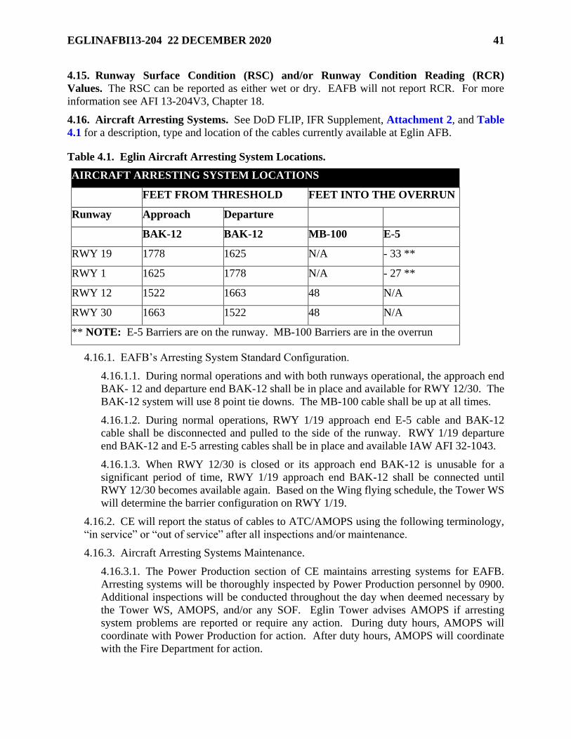
EGLINAFBI13-204 22 DECEMBER 2020 41
4.15. Runway Surface Condition (RSC) and/or Runway Condition Reading (RCR)
Values. The RSC can be reported as either wet or dry. EAFB will not report RCR. For more
information see AFI 13-204V3, Chapter 18.
4.16. Aircraft Arresting Systems. See DoD FLIP, IFR Supplement, Attachment 2, and Table
4.1 for a description, type and location of the cables currently available at Eglin AFB.
Table 4.1. Eglin Aircraft Arresting System Locations.
AIRCRAFT ARRESTING SYSTEM LOCATIONS
FEET FROM THRESHOLD FEET INTO THE OVERRUN
Runway Approach Departure
BAK-12 BAK-12 MB-100 E-5
RWY 19 1778 1625 N/A - 33 **
RWY 1 1625 1778 N/A - 27 **
RWY 12 1522 1663 48 N/A
RWY 30 1663 1522 48 N/A
** NOTE: E-5 Barriers are on the runway. MB-100 Barriers are in the overrun
4.16.1. EAFB’s Arresting System Standard Configuration.
4.16.1.1. During normal operations and with both runways operational, the approach end
BAK- 12 and departure end BAK-12 shall be in place and available for RWY 12/30. The
BAK-12 system will use 8 point tie downs. The MB-100 cable shall be up at all times.
4.16.1.2. During normal operations, RWY 1/19 approach end E-5 cable and BAK-12
cable shall be disconnected and pulled to the side of the runway. RWY 1/19 departure
end BAK-12 and E-5 arresting cables shall be in place and available IAW AFI 32-1043.
4.16.1.3. When RWY 12/30 is closed or its approach end BAK-12 is unusable for a
significant period of time, RWY 1/19 approach end BAK-12 shall be connected until
RWY 12/30 becomes available again. Based on the Wing flying schedule, the Tower WS
will determine the barrier configuration on RWY 1/19.
4.16.2. CE will report the status of cables to ATC/AMOPS using the following terminology,
“in service” or “out of service” after all inspections and/or maintenance.
4.16.3. Aircraft Arresting Systems Maintenance.
4.16.3.1. The Power Production section of CE maintains arresting systems for EAFB.
Arresting systems will be thoroughly inspected by Power Production personnel by 0900.
Additional inspections will be conducted throughout the day when deemed necessary by
the Tower WS, AMOPS, and/or any SOF. Eglin Tower advises AMOPS if arresting
system problems are reported or require any action. During duty hours, AMOPS will
coordinate with Power Production for action. After duty hours, AMOPS will coordinate
with the Fire Department for action.
42 EGLINAFBI13-204 22 DECEMBER 2020
4.16.3.2. All arresting systems maintenance must be pre-coordinated with and approved
by the Airfield Manager or a designated representative and will be conducted at a time
which ensures minimum impact to wing flying. Certifications will be scheduled Monday
through Friday, normally after the last sortie of the day. All certifications will take place
during daylight hours. Power Production is responsible for ensuring annual barrier
certifications are scheduled prior to the barrier expiring from service. AMOPS will
notify all affected agencies and assist Power Production in coordinating and scheduling
the engagement. Power Production will provide Airfield Manager a current copy of the
aircraft arresting system annual certification.
4.17. NOTAM Procedures. The NOTAM monitoring facility/dispatching facility for EAFB is
Eglin Tower/AMOPS respectively. AMOPS will receive, transmit, post and document required
NOTAM action IAW AFI 11-208_IP, Department of Defense NOTAM System.
4.17.1. All flying squadrons will obtain their required NOTAMs through the Defense
Internet NOTAM Service (DINS) manager site (https://www.notams.faa.gov). In the event
the NOTAM web sites are not operational, contact the destination airport via telephone to
obtain the most current NOTAMs. Contact Eglin AMOPS at COMM: (850) 882-5313/DSN:
872-5313 or via direct line to obtain local NOTAMs. Hurlburt Field AMOPS will
disseminate or dispatch NOTAMs as required for EAFB if the communication link to the Air
Force Central NOTAM facility is locally inoperative.
4.18. Airfield Maintenance. All airfield maintenance (e.g., all sweeper operations, grass
mowing, and general maintenance operations in the airfield environment) will be coordinated
and directed through AMOPS.
4.19. Airfield Tobacco Use Policy. There is no smoking on the airfield outside designated
tobacco use areas. For further guidance see AFI 40-102, Tobacco Free Living.
4.20. Photograph/Video on the Airfield and Ranges. Photography is normally not authorized
in restricted areas; however, if a valid need exists, permission can be obtained. A memorandum
will be generated by the requester and signed by the requesting commander; see EAFB Plan 31-
101, Integrated Defense Plan (FOUO), Tab D to Appendix 2 to Annex C. 96 TW/PA is the
approval authority for 96 TW restricted areas and 33 FW/PA is the approval authority for 33 FW
restricted areas. All other requests will be made through the appropriate control center, listed in
Table 4.2 If the requester does not possess unescorted entry privileges into the area, the unit
responsible for the area must provide an escort. Once approved, a copy of the memorandum
must be hand carried to 96 SFS/S3O, Bldg. 272, Room 101. A copy will be maintained on the
requester’s person while taking photographs. Prior to entering an area for photography, one of
the appropriate control centers will preannounce their intent by calling the Base Defense
Operations Center (BDOC) at COMM: (850) 882-2502/DSN: 872-2502 and Eglin/Duke
AMOPS at COMM: (850) 882-5313/DSN: 872-5313 or COMM: (850) 883-6538/DSN: 875-
6538 respectively. Copies of all approved memorandums will be distributed to 96 TW/PA and
96 TW/MOCC or 33 FW/PA and 33 FW/MOCC prior to the photography session.
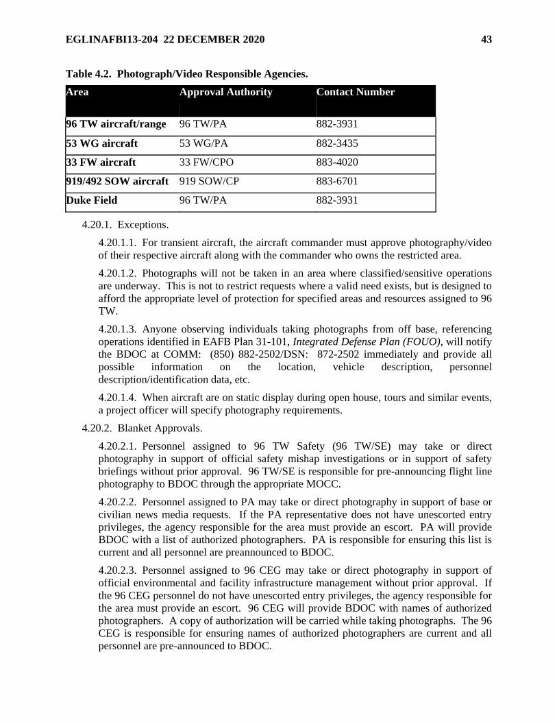
EGLINAFBI13-204 22 DECEMBER 2020 43
Table 4.2. Photograph/Video Responsible Agencies.
Area Approval Authority Contact Number
96 TW aircraft/range 96 TW/PA 882-3931
53 WG aircraft 53 WG/PA 882-3435
33 FW aircraft 33 FW/CPO 883-4020
919/492 SOW aircraft 919 SOW/CP 883-6701
Duke Field 96 TW/PA 882-3931
4.20.1. Exceptions.
4.20.1.1. For transient aircraft, the aircraft commander must approve photography/video
of their respective aircraft along with the commander who owns the restricted area.
4.20.1.2. Photographs will not be taken in an area where classified/sensitive operations
are underway. This is not to restrict requests where a valid need exists, but is designed to
afford the appropriate level of protection for specified areas and resources assigned to 96
TW.
4.20.1.3. Anyone observing individuals taking photographs from off base, referencing
operations identified in EAFB Plan 31-101, Integrated Defense Plan (FOUO), will notify
the BDOC at COMM: (850) 882-2502/DSN: 872-2502 immediately and provide all
possible information on the location, vehicle description, personnel
description/identification data, etc.
4.20.1.4. When aircraft are on static display during open house, tours and similar events,
a project officer will specify photography requirements.
4.20.2. Blanket Approvals.
4.20.2.1. Personnel assigned to 96 TW Safety (96 TW/SE) may take or direct
photography in support of official safety mishap investigations or in support of safety
briefings without prior approval. 96 TW/SE is responsible for pre-announcing flight line
photography to BDOC through the appropriate MOCC.
4.20.2.2. Personnel assigned to PA may take or direct photography in support of base or
civilian news media requests. If the PA representative does not have unescorted entry
privileges, the agency responsible for the area must provide an escort. PA will provide
BDOC with a list of authorized photographers. PA is responsible for ensuring this list is
current and all personnel are preannounced to BDOC.
4.20.2.3. Personnel assigned to 96 CEG may take or direct photography in support of
official environmental and facility infrastructure management without prior approval. If
the 96 CEG personnel do not have unescorted entry privileges, the agency responsible for
the area must provide an escort. 96 CEG will provide BDOC with names of authorized
photographers. A copy of authorization will be carried while taking photographs. The 96
CEG is responsible for ensuring names of authorized photographers are current and all
personnel are pre-announced to BDOC.
44 EGLINAFBI13-204 22 DECEMBER 2020
4.20.2.4. Official photographs are authorized for higher headquarters inspections as
indicated on the authenticated Entry Authorization List (EAL), which is signed by the
installation commander or designated representative(s).
4.20.2.5. Official photographs of crime scenes are authorized at the direction of Det 104,
AFOSI/CC and 96 SFS/CC.
4.20.2.6. All personnel assigned to the 96 OSS Airfield Operations Flight are authorized
to take photographs for official business on the airfield after coordinating with AMOPS.
4.20.2.7. Personnel assigned to perform maintenance and quality assurance functions are
authorized to take photos of their respective aircraft in the performance of their duties.
4.20.2.8. Aerial photographers assigned to 40 FLTS may take photographs in accordance
with mission requirements.
4.21. Wear of Hats. The Eglin Airfield is designated as a no-hat area IAW the 96 TW
supplement to AFI 21-101, Aircraft and Equipment Maintenance Management.
4.22. Scheduling and Flight Plan Procedures. IAW AFI 13-204V3, all aircraft departing Air
Force installations must have a flight plan on file (Stereo, VFR local, DD Form 175, Military
Flight Plan, or DD Form 1801, DoD International Flight Plan) with AMOPS prior to departure.
Flight plans must be filed in person unless there is an approved LOA on file between Airfield
Management and the user(s) or the organization is listed in Paragraph 4.22.1 of this instruction.
All flight plans will be maintained on file in accordance with Air Force RDS, Table 13-07, Rule
3.00.
4.22.1. The following flying units are authorized to file flight plans electronically and/or via
phone:
4.22.1.1. Units assigned to and/or TDY to the 96 TW, 33 FW, or 53 WG. TDY units
must have a mission number.
4.22.1.2. Civil Air Patrol/Eglin Composite Squadron.
4.22.1.3. Eglin Aero Club. Flight plans may be filed by telephone with AMOPS via the
Aero Club hotline only for those VFR local flights with no enroute stops. Touch-and-
go’s and taxi backs conducted for training purposes only are authorized at Eglin AFB,
Duke Field, Destin Airport and Bob Sikes Airport only. These flights will use an “Aero
Club” call sign and remain within a 50 NM radius of Eglin AFB.
4.22.2. Flight Join Up for Departure. When two or more aircraft with different call signs
wish to depart as a single flight, the aircraft in the lead will inform ATC as soon as possible,
i.e. “Racer 1 flight join up with Mozam 1, now a flight of four, request to taxi to RWY 12
with (ATIS Code).” This is not to be confused with the term MARSA which is discussed in
Paragraph 3.3.9 Instead, this will be handled as a flight join up. ATC must be notified as
soon as possible so appropriate flight plan amendments can be made in the NAS computer
system. If the joining flight wishes to keep their flight plan open, they will notify Clearance
Delivery so his/her flight plan can be retained and activated in the NAS system. If there is no
longer a need for the joining aircraft's flight plan, the flight plan can be removed from the
NAS system. ATC instructions will only be issued to the lead aircraft.
EGLINAFBI13-204 22 DECEMBER 2020 45
4.22.2.1. Clearance Delivery will place a remark on the flight plans identifying the call
signs of the other formations involved in the flight join up if the intent is to keep the
joining aircraft's flight plan available. For example, add a remark of "Plus Mozam flight"
on Racer's flight plan and "With Racer" on Mozam’s flight plan. Clearance Delivery will
send a Departure Message upon departure for the flight who has joined the lead flight so
the flight plan will be active in the system. This will allow the flight to return from the
airspace separately from the lead aircraft/flight.
4.22.2.2. If the joining aircraft/flight will remain with the lead aircraft throughout the
flight and does not wish to have the option to return separately, they shall inform ATC of
this intent and their flight plan will be removed from the NAS system and the number in
flight for the lead aircraft will be amended to show the total number in the flight. All
aircraft will use the lead aircraft's call sign (in sequence) from that point on. For
example, Mozam 1 and 2 would now be Racer 3 and 4 and Mozam 1's flight plan would
be removed.
4.22.2.3. Flights will be standard formation unless otherwise coordinated with ATC.
4.23. Controlled Movement Area (CMA). Eglin Tower is the controlling agency for all
ground traffic in the controlled movement areas. The CMA consists of runways, overruns, the
portion of all taxiways between the runway hold lines, and all grass between the distance
remaining markers and runway edges. Vehicles are required to be in radio contact with Eglin
Tower when operating on any part of the CMA.
4.23.1. Eglin Tower FM Nets (Ramp to Tower and Crash to Tower) are used solely for
communications on the airfield. Tower shall continuously monitor these nets during
vehicle/personnel operations on the CMA. Vehicles/personnel operating in the CMA shall
continuously monitor these nets and may transmit as necessary to ensure the safety/care of
personnel and/or equipment within the CMA.
4.23.2. No vehicle is authorized in, nor shall be approved to enter a CMA unless the vehicle
is radio equipped (or escorted by a radio-equipped vehicle) and in direct two-way contact
with Eglin Tower. Light gun signals for vehicle crossing of runways are not authorized at
Eglin AFB.
4.23.3. Vehicle Recall Procedures when Radio Communications Fail. In the event radio
contact is lost, exit the runway and controlled movement area immediately. Eglin Tower
may indicate that radio contact has been lost by raising and lowering the intensity level of the
runway lights or by flashing a red light in your direction.
4.23.4. CMA Vehicle/Pedestrian Operations: All personnel are required to abide by the
responsibilities and procedures for operating on or near the EAFB airfield outlined in EAFBI
13- 213V1, Eglin AFB Airfield Driving Instruction.
46 EGLINAFBI13-204 22 DECEMBER 2020
4.24. Precision Approach Critical Area. When the ceiling is reported less than 800 ft or
visibility less than 2 SM, no aircraft or vehicles will be allowed to operate within the ILS critical
areas or precision obstacle free zones depicted in Attachment 2 unless approved and in radio
contact with tower. In addition, aircraft and vehicles shall not transit the precision approach
critical areas or proceed beyond the INST hold lines when an aircraft executing an ILS approach
is inside the final approach fix. EAFB has ILS critical area stop lights in place along the
departure end of RWY 30 to signal when the critical zones must be protected. All vehicle traffic
along the airfield perimeter road shall strictly adhere to the ILS critical area stop lights when
activated by tower personnel.
4.25. Engine Test/Run-Up Areas and Procedures. Aircraft engine ground run-ups up to 100
percent power for maintenance purposes are authorized between 0600L-2300L. IAW AFI 11-
218, Aircraft Operations and Movement on the Ground, aircraft are required to contact Eglin
Tower prior to engine start. Exception: Engine run-ups coinciding with actual flight operations
are exempt from these restrictions and may be done on the runway and/or taxiways leading up to
the runway provided the aircraft is pointed in a safe direction with respect to personnel,
equipment and Foreign Object Debris (FOD).
4.25.1. Test Ramp: Engine run-ups at any power setting may be conducted in the sound
suppresser test cell or Hush House. Run-ups up to 85 percent power on the Test Ramp are
not restricted. Run-ups above 85 percent power outside the approved window in Paragraph
4.25 require approval from the 96 OG/CC or the 96 MXG/CC. Request approval through the
Eglin Command Post.
4.25.2. 33d RAMP: Engine run-ups are not restricted in the sound suppresser test cell.
Outside the sound suppresser test cell, engine run ups above 80 percent during the night quiet
hours (2301L- 0559L) require approval from the 33d Maintenance Group Commander (33
MXG/CC). Request approval through the Eglin Command Post.
4.25.3. C-130 Engine Maximum Power Run Areas: Idle speed engine runs are permitted
anywhere C-130 aircraft are authorized to park or taxi. There will be one vacant spot ahead
and two vacant spots behind the aircraft being run. The engine run supervisor is responsible
for posting an additional monitor aft of the aircraft being run to regulate vehicle and
pedestrian traffic behind the aircraft when engines are run at maximum power. The
following parking spot locations are designated as primary C-130 maximum power engine
run spots:
4.25.3.1. ALPHA 3 (aircraft nose facing south).
4.25.3.2. BRAVO 4 (aircraft nose facing north).
4.25.3.3. BRAVO 5 (aircraft nose facing north).
4.25.4. The aft monitor will be positioned in a vehicle on the taxiway between ALPHA and
BRAVO rows at least one spot east of the aircraft being run with vehicle lights and flashers
activated. The monitor vehicle is not required to have direct radio communication with the
aircraft but must be positioned to maintain line of sight with the engine run supervisor.
EGLINAFBI13-204 22 DECEMBER 2020 47
4.25.5. The following locations are designated as transient aircraft and alternate C-130
maximum power engine run spots as appropriate. An aft monitor should be posted behind
the aircraft as necessary to ensure safe operations. Approval from AMOPS is required before
using these locations except where noted.
4.25.5.1. TWY M-West.
4.25.5.2. TWY M between RWY 1/19 and TWY R (aircraft facing south).
4.25.5.3. HS-10 (west trim pad). Use shall be coordinated with 96 TW MOCC.
4.25.5.4. ALPHA Trim Pad from 1700L to 0700L (24 hours on weekends and holidays).
Use shall be coordinated with the 96 TW/MOCC.
4.26. Procedures for Suspending, Opening, and/or Closing the Runway.
4.26.1. Eglin Tower and AMOPS have authority to suspend runway operations anytime
there is an observed or reported hazardous condition or situation. Only AMOPS has the
authority to close or open the runway. Appropriate NOTAMs will be sent for
suspensions/closures of the runway that exceed 30 minutes.
4.26.2. Runway operations will be suspended to the affected runway during aircraft arresting
system changes. Aircraft may be allowed to taxi over a BAK-12 cable that has not been
secured with tie-down ropes as long as it has been connected and properly tensioned and the
pilot is informed that the cable is not tied down.
4.27. Airfield Inspections/Checks.
4.27.1. Airfield inspections and checks will be completed IAW requirements and procedures
outlined in AFI 13-204V3.
4.27.2. The requirement for the AFM to review and sign the daily AF Form 3616 is
delegated to the Deputy Airfield Manager (DAFM).
4.28. Aircraft Towing Procedures.
4.28.1. All Aero Club/Transient Aircraft. Prior coordination is required with AMOPS for all
aircraft tow operations at EAFB. AMOPS will relay this information to ATC. Direct two-
way radio contact and approval from Eglin Ground Control is required prior to any aircraft
being towed across any controlled movement area.
4.28.2. 96 TW/33 FW. Prior coordination with AMOPS or ATC is not required. Direct
two- way radio contact and approval from Eglin Tower is required prior to any aircraft being
towed across any controlled movement area.
4.29. Aeromedical Aircraft Arrival Procedures.
4.29.1. AMOPS shall coordinate crash/rescue stand-by protection for aeromedical aircraft if
required.
4.29.2. Eglin Tower shall notify AMOPS when arriving aeromedical airlift aircraft reach 15
NM from the airport and relay any information requested by the pilot.
4.30. Local Control Points. In addition to those published in the DoD FLIPs, local control
points listed in Table 4.3,; 4.4,; and depicted in Attachment 38 may be used for navigation and
control instructions.
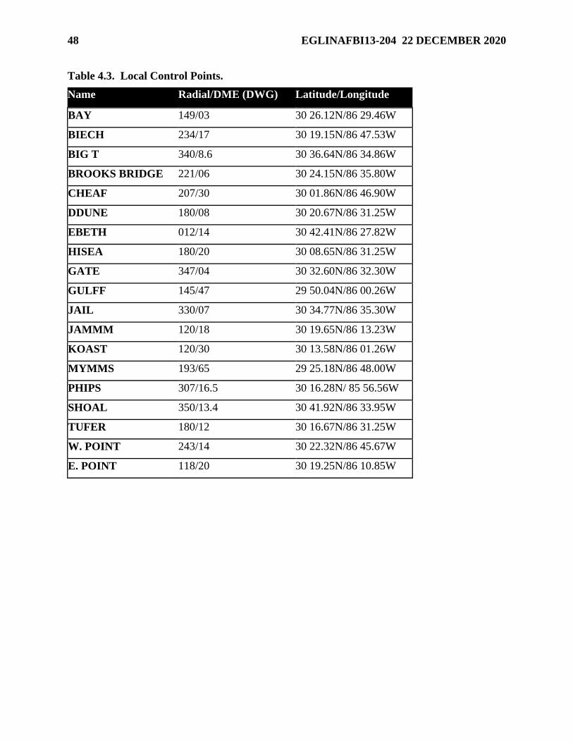
48 EGLINAFBI13-204 22 DECEMBER 2020
Table 4.3. Local Control Points.
Name Radial/DME (DWG) Latitude/Longitude
BAY 149/03 30 26.12N/86 29.46W
BIECH 234/17 30 19.15N/86 47.53W
BIG T 340/8.6 30 36.64N/86 34.86W
BROOKS BRIDGE 221/06 30 24.15N/86 35.80W
CHEAF 207/30 30 01.86N/86 46.90W
DDUNE 180/08 30 20.67N/86 31.25W
EBETH 012/14 30 42.41N/86 27.82W
HISEA 180/20 30 08.65N/86 31.25W
GATE 347/04 30 32.60N/86 32.30W
GULFF 145/47 29 50.04N/86 00.26W
JAIL 330/07 30 34.77N/86 35.30W
JAMMM 120/18 30 19.65N/86 13.23W
KOAST 120/30 30 13.58N/86 01.26W
MYMMS 193/65 29 25.18N/86 48.00W
PHIPS 307/16.5 30 16.28N/ 85 56.56W
SHOAL 350/13.4 30 41.92N/86 33.95W
TUFER 180/12 30 16.67N/86 31.25W
W. POINT 243/14 30 22.32N/86 45.67W
E. POINT 118/20 30 19.25N/86 10.85W
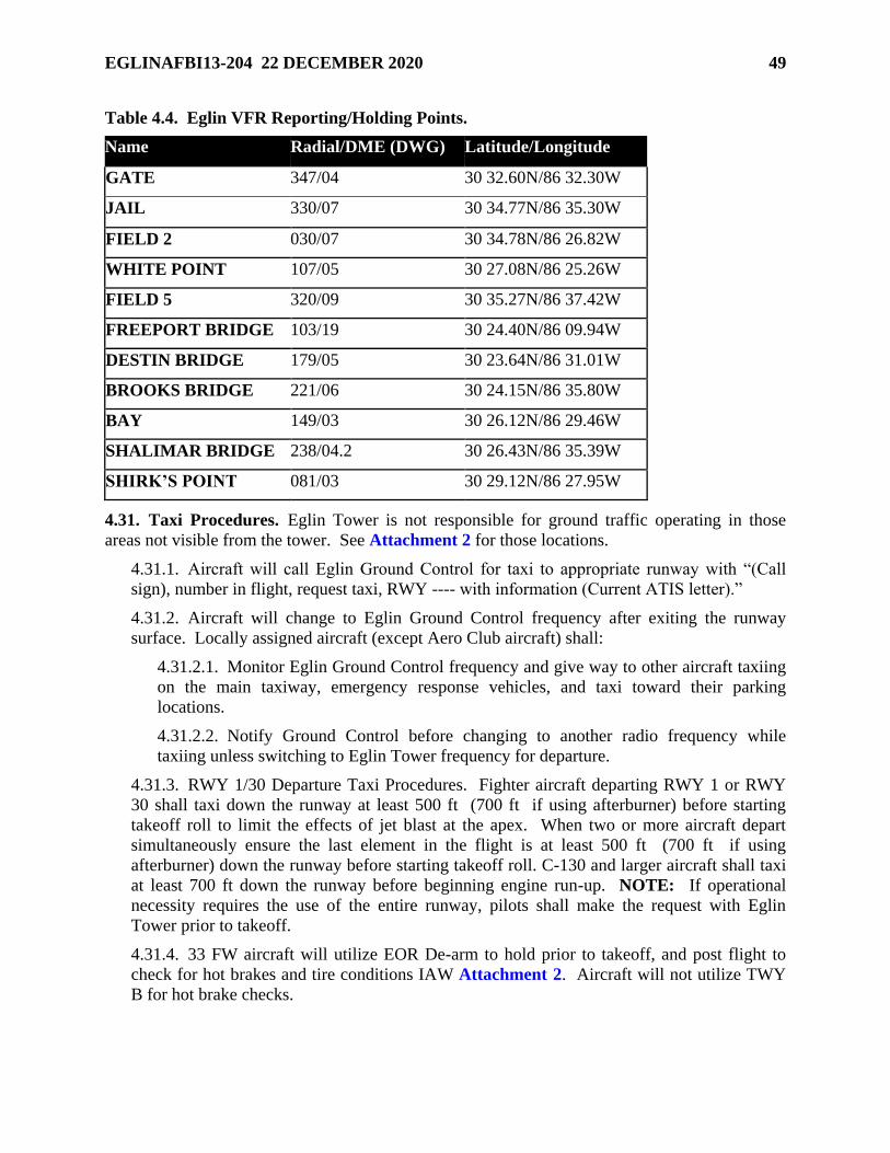
EGLINAFBI13-204 22 DECEMBER 2020 49
Table 4.4. Eglin VFR Reporting/Holding Points.
Name Radial/DME (DWG) Latitude/Longitude
GATE 347/04 30 32.60N/86 32.30W
JAIL 330/07 30 34.77N/86 35.30W
FIELD 2 030/07 30 34.78N/86 26.82W
WHITE POINT 107/05 30 27.08N/86 25.26W
FIELD 5 320/09 30 35.27N/86 37.42W
FREEPORT BRIDGE 103/19 30 24.40N/86 09.94W
DESTIN BRIDGE 179/05 30 23.64N/86 31.01W
BROOKS BRIDGE 221/06 30 24.15N/86 35.80W
BAY 149/03 30 26.12N/86 29.46W
SHALIMAR BRIDGE 238/04.2 30 26.43N/86 35.39W
SHIRK’S POINT 081/03 30 29.12N/86 27.95W
4.31. Taxi Procedures. Eglin Tower is not responsible for ground traffic operating in those
areas not visible from the tower. See Attachment 2 for those locations.
4.31.1. Aircraft will call Eglin Ground Control for taxi to appropriate runway with “(Call
sign), number in flight, request taxi, RWY ---- with information (Current ATIS letter).”
4.31.2. Aircraft will change to Eglin Ground Control frequency after exiting the runway
surface. Locally assigned aircraft (except Aero Club aircraft) shall:
4.31.2.1. Monitor Eglin Ground Control frequency and give way to other aircraft taxiing
on the main taxiway, emergency response vehicles, and taxi toward their parking
locations.
4.31.2.2. Notify Ground Control before changing to another radio frequency while
taxiing unless switching to Eglin Tower frequency for departure.
4.31.3. RWY 1/30 Departure Taxi Procedures. Fighter aircraft departing RWY 1 or RWY
30 shall taxi down the runway at least 500 ft (700 ft if using afterburner) before starting
takeoff roll to limit the effects of jet blast at the apex. When two or more aircraft depart
simultaneously ensure the last element in the flight is at least 500 ft (700 ft if using
afterburner) down the runway before starting takeoff roll. C-130 and larger aircraft shall taxi
at least 700 ft down the runway before beginning engine run-up. NOTE: If operational
necessity requires the use of the entire runway, pilots shall make the request with Eglin
Tower prior to takeoff.
4.31.4. 33 FW aircraft will utilize EOR De-arm to hold prior to takeoff, and post flight to
check for hot brakes and tire conditions IAW Attachment 2. Aircraft will not utilize TWY
B for hot brake checks.
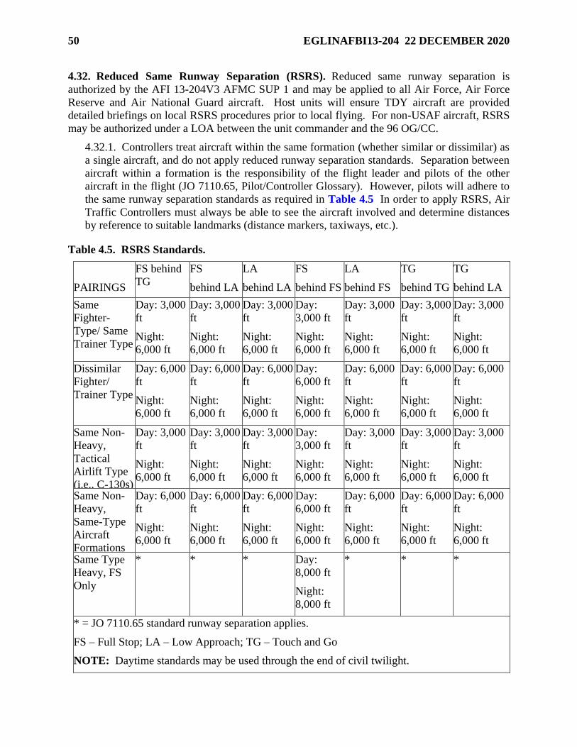
50 EGLINAFBI13-204 22 DECEMBER 2020
4.32. Reduced Same Runway Separation (RSRS). Reduced same runway separation is
authorized by the AFI 13-204V3 AFMC SUP 1 and may be applied to all Air Force, Air Force
Reserve and Air National Guard aircraft. Host units will ensure TDY aircraft are provided
detailed briefings on local RSRS procedures prior to local flying. For non-USAF aircraft, RSRS
may be authorized under a LOA between the unit commander and the 96 OG/CC.
4.32.1. Controllers treat aircraft within the same formation (whether similar or dissimilar) as
a single aircraft, and do not apply reduced runway separation standards. Separation between
aircraft within a formation is the responsibility of the flight leader and pilots of the other
aircraft in the flight (JO 7110.65, Pilot/Controller Glossary). However, pilots will adhere to
the same runway separation standards as required in Table 4.5 In order to apply RSRS, Air
Traffic Controllers must always be able to see the aircraft involved and determine distances
by reference to suitable landmarks (distance markers, taxiways, etc.).
Table 4.5. RSRS Standards.
PAIRINGS
FS behind
TG
FS
behind LA
LA
behind LA
FS
behind FS
LA
behind FS
TG
behind TG
TG
behind LA
Same
Fighter-
Type/ Same
Trainer Type
Day: 3,000
ft
Night:
6,000 ft
Day: 3,000
ft
Night:
6,000 ft
Day: 3,000
ft
Night:
6,000 ft
Day:
3,000 ft
Night:
6,000 ft
Day: 3,000
ft
Night:
6,000 ft
Day: 3,000
ft
Night:
6,000 ft
Day: 3,000
ft
Night:
6,000 ft
Dissimilar
Fighter/
Trainer Type
Day: 6,000
ft
Night:
6,000 ft
Day: 6,000
ft
Night:
6,000 ft
Day: 6,000
ft
Night:
6,000 ft
Day:
6,000 ft
Night:
6,000 ft
Day: 6,000
ft
Night:
6,000 ft
Day: 6,000
ft
Night:
6,000 ft
Day: 6,000
ft
Night:
6,000 ft
Same Non-
Heavy,
Tactical
Airlift Type
(i.e., C-130s)
Day: 3,000
ft
Night:
6,000 ft
Day: 3,000
ft
Night:
6,000 ft
Day: 3,000
ft
Night:
6,000 ft
Day:
3,000 ft
Night:
6,000 ft
Day: 3,000
ft
Night:
6,000 ft
Day: 3,000
ft
Night:
6,000 ft
Day: 3,000
ft
Night:
6,000 ft
Same Non-
Heavy,
Same-Type
Aircraft
Formations
Day: 6,000
ft
Night:
6,000 ft
Day: 6,000
ft
Night:
6,000 ft
Day: 6,000
ft
Night:
6,000 ft
Day:
6,000 ft
Night:
6,000 ft
Day: 6,000
ft
Night:
6,000 ft
Day: 6,000
ft
Night:
6,000 ft
Day: 6,000
ft
Night:
6,000 ft
Same Type
Heavy, FS
Only
* * * Day:
8,000 ft
Night:
8,000 ft
* * *
* = JO 7110.65 standard runway separation applies.
FS – Full Stop; LA – Low Approach; TG – Touch and Go
NOTE: Daytime standards may be used through the end of civil twilight.
EGLINAFBI13-204 22 DECEMBER 2020 51
4.32.2. When maintaining visual separation or operating under VFR, pilots are responsible
for wake turbulence separation, and controllers must provide appropriate cautionary wake
turbulence advisories. When aircraft are operating IFR or under ATC instructions, air traffic
controllers must ensure standard wake turbulence separation.
4.32.3. Reduced same runway separation is not authorized under the following conditions:
4.32.3.1. Any situation involving an emergency aircraft.
4.32.3.2. Non-AF aircraft, unless authorized under an LOA.
4.32.3.3. Any aircraft “Cleared for the option”, “Cleared stop-and-go”, low approach
behind a touch-and-go, or a touch-and-go behind a full stop.
4.32.3.4. When braking action reports of “medium”, “poor”, or “nil” are reported.
4.32.3.5. “Heavy” aircraft (capable of takeoff weight more than 255,000 pounds) other
than full stop following full stop.
4.33. General Departure Procedures.
4.33.1. Eglin Standard Departure. IFR aircraft initially departing EAFB shall be issued the
following departure instructions by Clearance Delivery: “FLY RUNWAY HEADING,
MAINTAIN THREE THOUSAND, EXPECT (altitude) ONE ZERO MINUTES AFTER
DEPARTURE….”
4.33.1.1. IFR aircraft issued a heading to fly on departure shall initiate their turn within 1
NM from the departure end of the runway, or advise ATC if unable.
4.33.2. VFR Overhead Pattern Protection. All departures from EAFB shall maintain at or
below 1,000 ft MSL, and Hurlburt Field shall maintain at or below 1,200 ft MSL, until the
departure end of the runway to protect the VFR overhead pattern, unless otherwise directed.
4.33.3. Quick Climbs/Max Climbs/Unrestricted Climbs/Functional Check Flights (FCF). If
a nonstandard rate of climb is desired, pilots will advise during initial contact with ground
control their intent for a max performance climb and requested altitude block. Eglin Tower,
in turn, will coordinate with the ERCF and inform the pilot if approved or disapproved.
Approval for max climbs will be contingent upon other traffic and/or airspace limitations.
4.33.4. Two minute call. All locally based or hosted aircraft departing IFR will call to Eglin
Ground Control: “(Call sign), 2 minutes” prior to departure. When ready for departure
inform Eglin Tower “(Call sign), number of aircraft in flight, ready for takeoff, RWY ___”
4.33.5. EAFB Intersection Departures (VFR and IFR). Intersection departures are
authorized from all taxiway intersections except from TWY M, due to obstructed visibility
from Eglin Tower. Eglin Tower will not issue runway distance remaining to locally based C-
130 and Aero Club aircraft making an intersection departure. NOTE: Aero Club aircraft are
expected to depart from TWY N for RWY 19 departures and TWY J for RWY 1 departures.
Aero Club multiengine aircraft will depart from TWY P for RWY 19 departures and TWY
W for RWY 1 departures.
4.33.5.1. The runway distances remaining from each of the taxiways at Eglin are as
depicted in Table 4.6
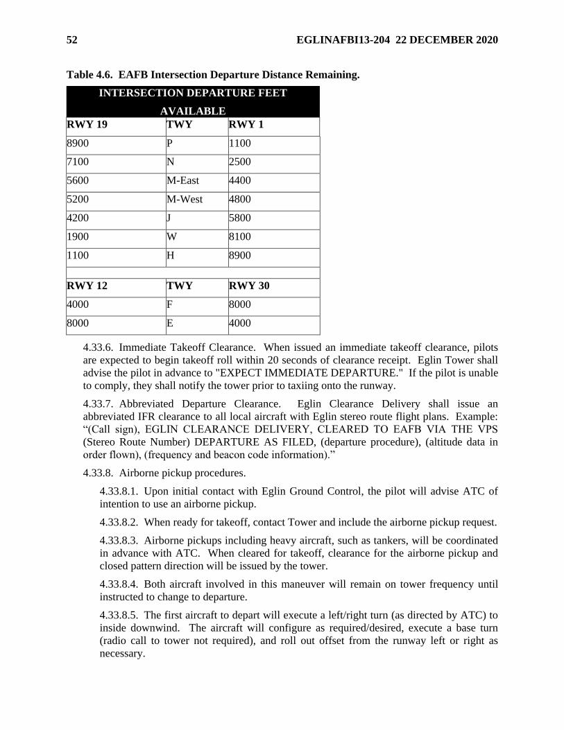
52 EGLINAFBI13-204 22 DECEMBER 2020
Table 4.6. EAFB Intersection Departure Distance Remaining.
INTERSECTION DEPARTURE FEET
AVAILABLE
RWY 19 TWY RWY 1
8900 P 1100
7100 N 2500
5600 M-East 4400
5200 M-West 4800
4200 J 5800
1900 W 8100
1100 H 8900
RWY 12 TWY RWY 30
4000 F 8000
8000 E 4000
4.33.6. Immediate Takeoff Clearance. When issued an immediate takeoff clearance, pilots
are expected to begin takeoff roll within 20 seconds of clearance receipt. Eglin Tower shall
advise the pilot in advance to "EXPECT IMMEDIATE DEPARTURE." If the pilot is unable
to comply, they shall notify the tower prior to taxiing onto the runway.
4.33.7. Abbreviated Departure Clearance. Eglin Clearance Delivery shall issue an
abbreviated IFR clearance to all local aircraft with Eglin stereo route flight plans. Example:
“(Call sign), EGLIN CLEARANCE DELIVERY, CLEARED TO EAFB VIA THE VPS
(Stereo Route Number) DEPARTURE AS FILED, (departure procedure), (altitude data in
order flown), (frequency and beacon code information).”
4.33.8. Airborne pickup procedures.
4.33.8.1. Upon initial contact with Eglin Ground Control, the pilot will advise ATC of
intention to use an airborne pickup.
4.33.8.2. When ready for takeoff, contact Tower and include the airborne pickup request.
4.33.8.3. Airborne pickups including heavy aircraft, such as tankers, will be coordinated
in advance with ATC. When cleared for takeoff, clearance for the airborne pickup and
closed pattern direction will be issued by the tower.
4.33.8.4. Both aircraft involved in this maneuver will remain on tower frequency until
instructed to change to departure.
4.33.8.5. The first aircraft to depart will execute a left/right turn (as directed by ATC) to
inside downwind. The aircraft will configure as required/desired, execute a base turn
(radio call to tower not required), and roll out offset from the runway left or right as
necessary.
EGLINAFBI13-204 22 DECEMBER 2020 53
4.33.8.6. The second aircraft will release brakes and the airborne aircraft will execute the
join up. When both aircraft are at a safe altitude, tower will direct them to change to
departure.
4.33.8.7. ATC may have first airborne aircraft “report initial for airborne pickup/carry
through” if conditions warrant. Additionally, the pilot may request “re-entry to initial for
airborne pickup” if desired (subject to ATC approval).
4.33.8.8. Restrictions.
4.33.8.8.1. Simultaneous operations to crossing runway are prohibited during
airborne pickup operations.
4.33.8.8.2. Weather minimums for executing the airborne pickup procedure shall be
a 2,100 ft MSL ceiling and 3 statute miles (SM) visibility.
4.33.8.8.3. Aircraft will slow to no lower than final approach speed during the
airborne pickup.
4.33.8.8.4. Minimum altitude during the airborne pickup is 200 ft AGL unless
approved by test and safety review boards for specific test mission requirements.
4.33.9. Avoiding Restricted Airspace. Reduced separation may be applied to the periphery
of restricted airspace for participating aircraft departing Eglin AFB ONLY. All aircraft will
be considered participating with the exception of Air Carriers, civil aircraft (unless
participating in scheduled missions), heavy aircraft, or transient aircraft. Operations will be
conducted IAW the following:
4.33.9.1. Host unit will be responsible for briefing all aircraft they sponsor of the
reduced minima being applied by ERCF for aircraft departing Eglin AFB. Tower will
notify departure of airspace affecting the departure and ERCF will flight follow
participating aircraft, providing safety alerts/traffic advisories as necessary to help
prevent an encroachment into active restricted airspace. Responsibility rests with the
aircraft commander to laterally/vertically avoid the area.
4.33.9.2. ERCF will suspend restricted area operations affecting a participating departure
if the aircrew determines they cannot remain outside restricted airspace. Expect a five-
/ten-minute delay in such situations.
4.34. General Recovery Procedures.
4.34.1. On initial contact with Eglin Tower, specify position and landing intentions [i.e.,
“EGLIN TOWER, (call sign), DDUNE INITIAL RWY 12 OPTION”].
4.34.2. South Flow Recovery Procedures. The South Flow Recovery procedure is designed
to provide IFR or VFR recoveries during RWY 12/19 operations. Aircraft shall remain on
ERCF frequency until instructed to contact Eglin Tower. Aircraft will be cleared and fly the
recovery as depicted (See Attachment 17). IFR clearance is automatically canceled when
the aircraft reports the field in sight. Aircraft reporting the field in sight are expected to fly to
initial unless otherwise coordinated. The VFR portion of the Eglin South Recovery shall not
be flown when the ceiling is less than 2,100 ft MSL.
54 EGLINAFBI13-204 22 DECEMBER 2020
4.34.2.1. DDUNE Recovery. This procedure is utilized during south flow (RWY 12/19)
operations to return aircraft to the VFR pattern. Aircraft shall remain on ERCF
frequency until instructed to contact Eglin Tower. Aircraft will be cleared and fly the
recovery as depicted (See Attachment 17). IFR clearance is automatically canceled
when the aircraft reports the field in sight. Aircraft reporting the field in sight are
expected to fly GATE to initial unless otherwise coordinated. If unable to proceed VFR
by GATE, continue outbound on the DWG R-347 for an instrument approach.
4.34.2.1.1. From DDUNE, proceed to DWG via DWG R-180; cross DWG at 4,000 ft
MSL (See Attachment 17). At DWG, track outbound on DWG R-347 to GATE
(DWG 347/04). Cross GATE between 2,100 and 3,000 ft MSL. Descend to pattern
altitude and proceed to initial, straight-in, or as instructed by Eglin Tower.
4.34.2.1.2. North Transition: Proceed to EBETH (DWG012/14) at or above 3,000 ft
MSL then proceed direct to JAIL (DWG 330/07) to cross JAIL between 2,200 and
3,000 ft MSL, then proceed to GATE (DWG 347/04) to cross GATE between 2,100
and 3,000 ft MSL (See Attachment 17). Descend to pattern altitude and proceed to
initial, straight-in, or as instructed by Eglin Tower. If recovering in IMC, proceed to
EBETH to pick up the ILS to RWY 19. Cross EBETH at or above 3,000 ft MSL.
4.34.2.1.3. East Transition: Intercept the 86º0’W longitude line and track 360° to
KOAST (DWG 120/30) (See Attachment 17). Cross GULFF (DWG 145/047)
between 15,000 and 19,000 ft MSL; cross KOAST between 6,000 and 9,000 ft
MSL, then turn left and proceed to DDUNE (DWG 180/08) via course 286°; cross
DDUNE at or above 6,000 ft MSL, then proceed with the DDUNE recovery.
4.34.2.1.4. West Transition: Intercept the 86º48’W longitude line and track 360° to
BIECH (DWG 236/17) (See Attachment 17). Cross CHEAF (DWG 207/30)
between 15,000 and 19,000 ft MSL; cross BIECH between 6,000 and 9,000 ft MSL,
then turn right and proceed to DDUNE (DWG 180/08) via course 083°; cross
DDUNE at or above 6,000 ft MSL, then proceed with the DDUNE recovery.
4.34.2.2. Whiskey Hotel Recovery: This procedure is designed to provide a VFR
recovery to EAFB during RWY 12/19 operations. The minimum weather for this
recovery is a 3,500 ft MSL ceiling and 3 SM visibility (See Attachment 18).
4.34.2.2.1. R-2915B activities may preclude Whiskey Hotel recoveries.
4.34.2.2.2. Once approved, IFR clearances and radar arrival sequencing are
automatically canceled. Radar flight following service shall continue until
communications transfer to Eglin Tower.
4.34.2.2.3. Aircraft shall cross the Hurlburt TACAN (Channel 45X) at or above
3,000 ft MSL, cross abeam B-71 at 2,500 ft MSL, and then descend to 1,600 ft
MSL for initial or proceed straight-in.
4.34.2.2.4. Aircraft shall remain clear of R-2915A throughout the recovery.
EGLINAFBI13-204 22 DECEMBER 2020 55
4.34.2.3. Brooks Bridge Recovery: This procedure is designed to provide a VFR
recovery option to EAFB during RWY 12/19 operations. The minimum weather for this
recovery is a 2,600 ft MSL ceiling and 3 SM visibility. Once approved “Brooks Bridge
recovery,” IFR clearances and radar arrival sequencing are automatically cancelled.
Radar flight following services shall continue until communications transfer to Eglin
tower.
4.34.2.3.1. Pilots will report BROOKS BRIDGE (DWG 221/6) between 2,100 and
3,500 ft MSL with intentions. When weather allows (aircraft must maintain 500 feet
below lowest weather), aircrew will strive to enter at the top of the block for noise
abatement and reduce throttle settings over populated areas in the descent. Normal
intentions aircraft may request with Tower include: 1) direct to initial; or 2) direct to
a VFR straight-in for RWY 12. Pilots will maintain a minimum of 2,100 ft MSL
until cleared to descend to initial or VFR straight-in altitudes.
4.34.2.3.2. If Tower is unable to sequence traffic entering the pattern via BROOKS
BRIDGE to initial or to a straight-in for RWY 12, pilots will proceed direct to the
DWG TACAN and then direct GATE at a minimum of 2,100 ft MSL to re-enter the
pattern flow and deconflict with normal pattern traffic at 1,600 ft MSL.
4.34.3. North Flow Recovery Procedures. The North Flow Recovery procedure is designed
to provide IFR or VFR recoveries during RWY 1/30 operations. Aircraft shall remain on
ERCF frequency until instructed to contact Eglin Tower. Aircraft will be cleared and fly the
recovery as depicted (See Attachment 19). IFR clearance is automatically canceled when
the aircraft reports the field in sight. Aircraft reporting the field in sight are expected to fly to
initial unless otherwise coordinated. The VFR portion of the Eglin North Recovery shall not
be flown when the ceiling is less than 2,100 ft MSL.
4.34.3.1. North Transition. Intercept the DWG R-012 and track inbound to DWG.
Cross DWG R-012/14 DME (EBETH) at 6,000 ft MSL; cross DWG between 4,000 and
6,000 ft MSL (See Attachment 19). At DWG, track outbound to DDUNE (DWG
180/08) via R-180; cross DWG 180/04 (DUTBE) between 2,100 and 5,000 ft MSL; cross
DDUNE between 1,600 and 5,000 ft MSL. Then recover via procedures stated below:
4.34.3.1.1. VFR Recovery. Descend to pattern altitude and proceed to initial, VFR
straight-in, or as instructed by ATC. If unable to proceed VMC, aircraft shall advise
ATC and proceed with the IFR portion of the recovery.
4.34.3.1.2. IFR Recovery. In the absence of further ATC instructions, depart
DDUNE heading 133° to join the DWG 12 DME arc. Upon joining the arc, proceed
with the published ILS or TACAN approach to RWY 30. Maintain 3,000 ft MSL
throughout the 12 DME arc until passing the lead radial for the intended approach.
4.34.3.2. East Transition. If a heading or restriction is not assigned by EMC, intercept
the 86º0’W longitude line and track 360 degrees to KOAST (DWG 120/30) (See
Attachment 19). Cross GULFF (DWG 145/57) between 15,000 and 19,000 ft MSL;
cross KOAST between 6,000 and 9,000 ft MSL, then turn left and proceed inbound via
DWG R-120. Cross JAMMM (DWG 120/18) at or above 3,000 ft MSL. Then depart
JAMMM and join ILS or TACAN procedures as stated below:
56 EGLINAFBI13-204 22 DECEMBER 2020
4.34.3.2.1. ILS Approach. Depart JAMMM to join the procedure at DWG 120/17
and proceed with the approach.
4.34.3.2.2. TACAN RWY 30 Approach. Depart JAMMM heading 280°, intercept
the DWG R- 133 and proceed with the approach.
4.34.3.3. West Transition. Intercept the 86º48’W longitude line and track 360° to
BIECH (DWG 236/17) (See Attachment 19). Cross CHEAF (DWG 207/30) between
15,000 and 19,000 ft MSL; cross BIECH between 6,000 and 9,000 ft MSL, then turn
right and proceed to DEJAH (DWG 218/11) via course 083°; cross DEJAH at 3,000 ft
MSL, then proceed to DDUNE (DWG 180/08). Cross DDUNE between 2,000 and 1,600
ft MSL. Then recover via procedures stated below:
4.34.3.3.1. VFR Recovery. Descend to pattern altitude and proceed to initial, VFR
straight-in, or as instructed by ATC. If unable to proceed VMC, aircraft shall advise
ATC and proceed with the IFR portion of the recovery.
4.34.3.3.2. IFR Recovery. In the absence of further ATC instructions, depart
DDUNE heading 133° to join the DWG 12 DME arc. Upon joining the arc, proceed
with the published ILS or TACAN approach to RWY 30. Climb and maintain 3,000
ft MSL throughout the 12 DME arc until passing the lead radial for the intended
approach.
4.34.4. Local Climbout and Radar Traffic Patterns. Aircraft making multiple approaches at
Eglin shall use the following climbout instructions unless otherwise directed by ATC.
Aircraft making multiple radar approaches can expect vectors for a pattern as depicted in
Attachment 16 or as controller workload dictates.
4.34.4.1. ATC phraseology for base assigned aircraft shall be “EXECUTE LOCAL
CLIMBOUT.” If multiple approaches will be made with tower, phraseology shall be
“AFTER COMPLETING (type approach), MAINTAIN VFR, CONTACT TOWER.”
4.34.4.2. Eglin Local Climbout:
4.34.4.2.1. RWY 1: “AFTER COMPLETING (type approach), CROSS
DEPARTURE END OF THE RUNWAY AT OR BELOW ONE THOUSAND,
CLIMB AND MAINTAIN THREE THOUSAND, THEN TURN RIGHT HEADING
ONE ONE ZERO, CONTACT ARRIVAL 124.25/290.5/LOCAL CHANNEL 7.”
4.34.4.2.2. RWY 12: “AFTER COMPLETING (type approach), CROSS
DEPARTURE END OF THE RUNWAY AT OR BELOW ONE THOUSAND, FLY
RUNWAY HEADING, CLIMB AND MAINTAIN FOUR THOUSAND, AT
THREE DME TURN LEFT HEADING ZERO THREE ZERO, CONTACT
ARRIVAL 124.25/290.5/LOCAL CHANNEL 7.”
4.34.4.2.3. RWY 19: “AFTER COMPLETING (type approach), CROSS
DEPARTURE END OF THE RUNWAY AT OR BELOW ONE THOUSAND,
TURN RIGHT HEADING TWO SEVEN ZERO, CLIMB AND MAINTAIN
THREE THOUSAND, CONTACT ARRIVAL 124.25/290.5/LOCAL CHANNEL 7.”
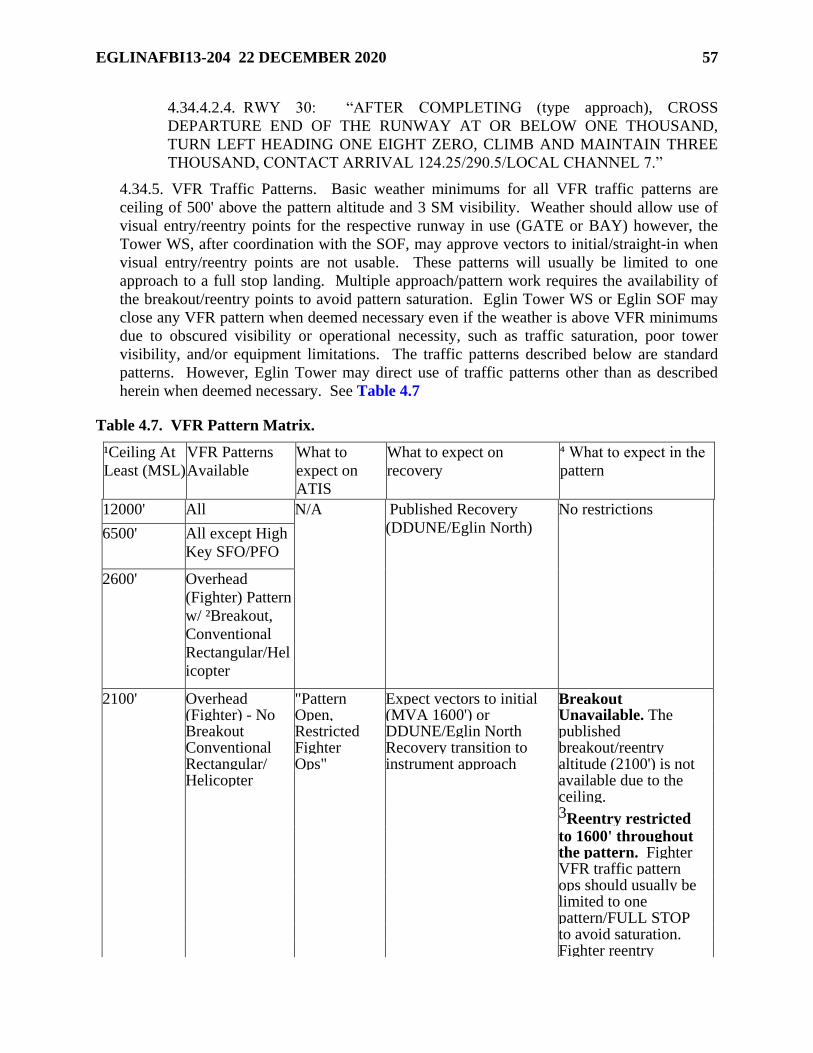
EGLINAFBI13-204 22 DECEMBER 2020 57
4.34.4.2.4. RWY 30: “AFTER COMPLETING (type approach), CROSS
DEPARTURE END OF THE RUNWAY AT OR BELOW ONE THOUSAND,
TURN LEFT HEADING ONE EIGHT ZERO, CLIMB AND MAINTAIN THREE
THOUSAND, CONTACT ARRIVAL 124.25/290.5/LOCAL CHANNEL 7.”
4.34.5. VFR Traffic Patterns. Basic weather minimums for all VFR traffic patterns are
ceiling of 500' above the pattern altitude and 3 SM visibility. Weather should allow use of
visual entry/reentry points for the respective runway in use (GATE or BAY) however, the
Tower WS, after coordination with the SOF, may approve vectors to initial/straight-in when
visual entry/reentry points are not usable. These patterns will usually be limited to one
approach to a full stop landing. Multiple approach/pattern work requires the availability of
the breakout/reentry points to avoid pattern saturation. Eglin Tower WS or Eglin SOF may
close any VFR pattern when deemed necessary even if the weather is above VFR minimums
due to obscured visibility or operational necessity, such as traffic saturation, poor tower
visibility, and/or equipment limitations. The traffic patterns described below are standard
patterns. However, Eglin Tower may direct use of traffic patterns other than as described
herein when deemed necessary. See Table 4.7
Table 4.7. VFR Pattern Matrix.
¹Ceiling At
Least (MSL)
VFR Patterns
Available
What to
expect on
ATIS
What to expect on
recovery
⁴ What to expect in the
pattern
12000' All N/A Published Recovery
(DDUNE/Eglin North)
No restrictions
6500' All except High
Key SFO/PFO
2600' Overhead
(Fighter) Pattern
w/ ²Breakout,
Conventional
Rectangular/Hel
icopter
2100' Overhead "Pattern Expect vectors to initial Breakout (Fighter) - No Open, (MVA 1600') or Unavailable. The Breakout Restricted DDUNE/Eglin North published Conventional Fighter Recovery transition to breakout/reentry Rectangular/ Ops" instrument approach altitude (2100') is not Helicopter available due to the ceiling. 3Reentry restricted to 1600' throughout the pattern. Fighter VFR traffic pattern ops should usually be limited to one pattern/FULL STOP to avoid saturation. Fighter reentry
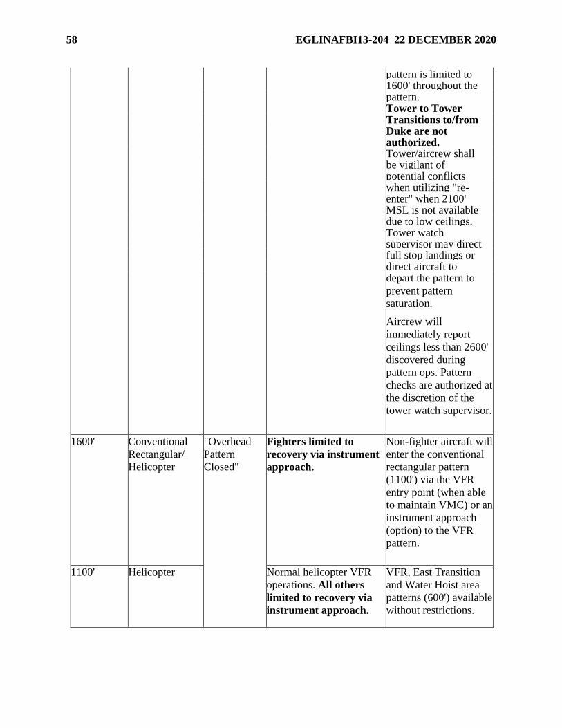
58 EGLINAFBI13-204 22 DECEMBER 2020
pattern is limited to 1600' throughout the pattern. Tower to Tower Transitions to/from Duke are not authorized. Tower/aircrew shall be vigilant of potential conflicts when utilizing "re- enter" when 2100' MSL is not available due to low ceilings. Tower watch supervisor may direct full stop landings or direct aircraft to depart the pattern to
prevent pattern
saturation.
Aircrew will
immediately report
ceilings less than 2600'
discovered during
pattern ops. Pattern
checks are authorized at
the discretion of the
tower watch supervisor.
1600' Conventional
Rectangular/
Helicopter
"Overhead
Pattern
Closed"
Fighters limited to
recovery via instrument
approach.
Non-fighter aircraft will
enter the conventional
rectangular pattern
(1100') via the VFR
entry point (when able
to maintain VMC) or an
instrument approach
(option) to the VFR
pattern.
1100' Helicopter Normal helicopter VFR
operations. All others
limited to recovery via
instrument approach.
VFR, East Transition
and Water Hoist area
patterns (600') available
without restrictions.
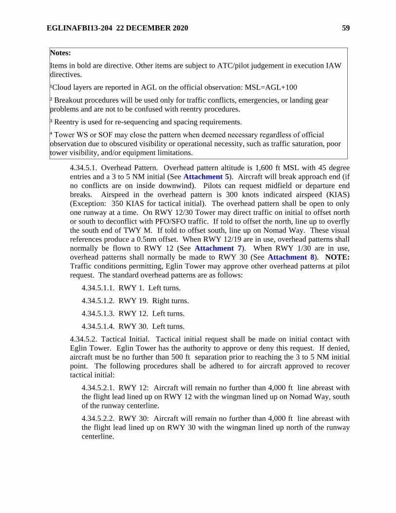
EGLINAFBI13-204 22 DECEMBER 2020 59
Notes:
Items in bold are directive. Other items are subject to ATC/pilot judgement in execution IAW
directives.
¹Cloud layers are reported in AGL on the official observation: MSL=AGL+100
² Breakout procedures will be used only for traffic conflicts, emergencies, or landing gear
problems and are not to be confused with reentry procedures.
³ Reentry is used for re-sequencing and spacing requirements.
⁴ Tower WS or SOF may close the pattern when deemed necessary regardless of official
observation due to obscured visibility or operational necessity, such as traffic saturation, poor
tower visibility, and/or equipment limitations.
4.34.5.1. Overhead Pattern. Overhead pattern altitude is 1,600 ft MSL with 45 degree
entries and a 3 to 5 NM initial (See Attachment 5). Aircraft will break approach end (if
no conflicts are on inside downwind). Pilots can request midfield or departure end
breaks. Airspeed in the overhead pattern is 300 knots indicated airspeed (KIAS)
(Exception: 350 KIAS for tactical initial). The overhead pattern shall be open to only
one runway at a time. On RWY 12/30 Tower may direct traffic on initial to offset north
or south to deconflict with PFO/SFO traffic. If told to offset the north, line up to overfly
the south end of TWY M. If told to offset south, line up on Nomad Way. These visual
references produce a 0.5nm offset. When RWY 12/19 are in use, overhead patterns shall
normally be flown to RWY 12 (See Attachment 7). When RWY 1/30 are in use,
overhead patterns shall normally be made to RWY 30 (See Attachment 8). NOTE:
Traffic conditions permitting, Eglin Tower may approve other overhead patterns at pilot
request. The standard overhead patterns are as follows:
4.34.5.1.1. RWY 1. Left turns.
4.34.5.1.2. RWY 19. Right turns.
4.34.5.1.3. RWY 12. Left turns.
4.34.5.1.4. RWY 30. Left turns.
4.34.5.2. Tactical Initial. Tactical initial request shall be made on initial contact with
Eglin Tower. Eglin Tower has the authority to approve or deny this request. If denied,
aircraft must be no further than 500 ft separation prior to reaching the 3 to 5 NM initial
point. The following procedures shall be adhered to for aircraft approved to recover
tactical initial:
4.34.5.2.1. RWY 12: Aircraft will remain no further than 4,000 ft line abreast with
the flight lead lined up on RWY 12 with the wingman lined up on Nomad Way, south
of the runway centerline.
4.34.5.2.2. RWY 30: Aircraft will remain no further than 4,000 ft line abreast with
the flight lead lined up on RWY 30 with the wingman lined up north of the runway
centerline.
60 EGLINAFBI13-204 22 DECEMBER 2020
4.34.5.2.3. RWY 1/19: Aircraft will remain no further than 4,000 ft line abreast
with the flight lead lined up on RWY 1/19 with the wingman east of the runway
centerline.
4.34.5.3. VFR Straight-in. Altitude for a VFR straight-in approach is 1,100 ft MSL on a
3 to 5 NM final. When entering from a downwind or GATE (DWG 347/04), aircraft will
begin their descent when turning base and be established at 1,100 ft MSL prior to turning
final. RWY 30 south straight-in entries shall maintain 2,100 ft MSL until BAY (DWG
149/03) to avoid Destin Airport traffic, then descend to 1,100 ft MSL. Maneuvering to
the southeast may be required to execute RWY 30 straight-in approaches.
4.34.5.4. Reentries. Reentry is used for re-sequencing and spacing requirements. The
radio call for reentry is [“(Call sign), REENTER”]. When directed to, or when
requesting to reenter, aircraft flying straight through initial will climb and maintain 2,100
ft MSL until the departure end of the runway. Aircraft on climbout after a low-
approach/touch-and-go will maintain at or below 1,000 ft MSL until the departure end of
the runway and clear of inside downwind traffic. All aircraft reentering will turn
crosswind or maneuvering for re-entry at departure end and climb/maintain 2,100 ft MSL
unless instructed by tower. Aircraft will remain within 4 NM of the airport when
reentering the pattern. The following are the standard reentry procedures for RWY 12/30
and RWY 1/19:
4.34.5.4.1. The standard reentry point for RWY 12 is GATE. Aircraft will proceed
direct GATE once over Choctawhatchee Bay (feet wet) and at 2,100 ft MSL. Pilots
will strive to be rolled out towards GATE as they are leveling at 2,100 ft MSL
(similar to completing a closed pull-up). If reentering for a VFR straight-in, apply
VFR straight-in altitude procedures described in Paragraph 4.34.5.3
4.34.5.4.2. The standard reentry point for RWY 30 is BAY. On crosswind, aircraft
will maintain 2,100 ft MSL and turn left direct to BAY (east of DTS RWY 32
centerline). At BAY, the aircraft will turn to make a 45- degree entry to 3 NM initial
while descending to 1,600 ft MSL. If reentering for a VFR straight- in, apply VFR
straight-in altitude procedures described in Paragraph 4.34.5.3
4.34.5.4.3. The standard reentry point for RWY 19 is GATE. On crosswind, aircraft
will maintain 2,100 ft MSL and turn right to outside downwind approximately twice
the distance from the runway as inside downwind and then fly direct to GATE.
Aircraft will remain east of the approach end of RWY 12 until north of RWY 12. At
GATE, the aircraft will turn to make a 45-degree entry to 3 NM initial while
descending to 1,600 ft MSL. If reentering for a VFR straight-in, apply VFR straight-
in altitude procedures described in Paragraph 4.34.5.3
4.34.5.4.4. The standard reentry point for RWY 1 is SHALIMAR BRIDGE (DWG
238/4.2). On crosswind, aircraft will maintain 2,100 ft MSL and turn left to fly direct
to SHALIMAR BRIDGE. At SHALIMAR BRIDGE, the aircraft will turn to make a
45-degree entry to 3 NM initial while descending to 1,600 ft MSL. If reentering for a
VFR straight-in, apply VFR straight-in altitude procedures described in Paragraph
4.34.5.3
EGLINAFBI13-204 22 DECEMBER 2020 61
4.34.5.5. Go Around. Aircraft instructed “(Call sign), GO AROUND, (Reason, time
permitting)” will execute the following procedures:
4.34.5.5.1. Aircraft will fly straight ahead or as directed by the Eglin Tower. [e.g.,
“(Call sign), GO AROUND, SOUTH SIDE OF RUNWAY, AIRCRAFT ON
RUNWAY”] and maintain at or below 1,000 ft MSL until departure end.
4.34.5.6. Breakouts. Breakout procedures will be used only for traffic conflicts,
emergencies, or landing gear problems and are not to be confused with reentry
procedures. The radio call for breakouts are “(Call sign) BREAKOUT” or when initiated
by the pilot, “(Call sign) BREAKING OUT.” Aircraft will execute the following
breakout procedures when directed by Eglin Tower or as required. (See Attachments 7
and 8)
4.34.5.6.1. Aircraft conducting overhead approaches: Aircraft established on initial
have priority over aircraft 45-degree to initial. If a conflict exists, aircraft on 45-
degree to initial will immediately climb to 2,100 ft MSL, notify tower of the climb to
2,100 ft MSL [“(Call sign), BREAKING-OUT”] and turn to parallel/overfly the
runway. Continue runway heading until departure end, then follow Eglin Tower’s
instructions. If no instructions are received, extend upwind 1.5 NM past the departure
end of the runway and turn crosswind. Clear traffic reentering and turn to outside
downwind. Once established on outside downwind, follow the normal reentry
procedures for the runway in use and expect further tower instructions at reentry
points.
4.34.5.6.2. Aircraft Established on Downwind. When directed by Eglin Tower to
breakout, or when a pilot initiates a breakout from inside downwind, the aircraft will
climb and maintain 2,100 ft MSL, immediately turn and proceed to the reentry point
for the runway in use. The pilot must check for aircraft established on outside
downwind. RWY 12/19, if a conflict exists with an aircraft on outside downwind the
aircraft breaking out will maneuver to follow the outside downwind traffic to GATE.
RWY 30, after clearing outside downwind, climb and maintain 2,100 ft MSL to avoid
Destin Airport traffic and follow any outside downwind traffic to BAY. RWY 1,
after clearing outside downwind, climb and maintain 2,100 ft MSL and follow any
outside downwind traffic to SHALIMAR BRIDGE. At GATE/BAY/SHALIMAR
BRIDGE, the aircraft will follow the normal reentry procedures or proceed as
directed by Eglin Tower personnel.
4.34.5.6.3. Aircraft Established on Base Turn: Aircraft on a straight-in have priority
over aircraft in the overhead pattern. Aircraft that have commenced a base turn and
perceive a traffic conflict (or have an aircraft malfunction) will not break out but
instead will continue the turn to the runway in use while maneuvering to avoid
straight-in traffic and immediately inform Eglin Tower [“(Call sign), GOING
AROUND”]. If possible, once aircraft separation is assured, offset to the inside of
the runway in use (left side for RWY 1/12/30 and right side for RWY 19). Aircraft
will maintain at or below 1,000 ft MSL until departure end of runway, and request
closed, reenter, or proceed as directed by Eglin Tower.
62 EGLINAFBI13-204 22 DECEMBER 2020
4.34.5.6.4. Aircraft Established on Straight-in Approach: Aircraft established on a
straight-in approach have priority over aircraft in the overhead traffic pattern and will
continue with the approach while monitoring base turn traffic that is maneuvering to
resolve the conflict. If straight-in traffic must also maneuver to ensure flight path
separation, aircraft shall clear prior to maneuvering to avoid potential conflicts with
other aircraft in the pattern After maneuvering, parallel the runway, remain below
1,000 ft MSL until the departure end of the runway and proceed as directed by Eglin
Tower.
4.34.5.7. Eglin Apex Separation. When an aircraft is on base leg or on a straight-in final
and the potential exists for a conflict at the Eglin “Apex”, aircraft will be issued the
conflicting traffic information and instructed to “EXPECT MIDFIELD CLOSED” as a
last means of providing “Apex” separation. Pilots who inform the Eglin Tower they are
unable to accept a midfield closed can expect to be broken out and instructed to reenter
the traffic pattern. If, after the aircraft turns final, it is determined that a midfield closed
is not required, tower shall advise the aircraft to make a normal closed (departure end)
and issue applicable traffic.
4.34.5.8. ATC shall approve closed traffic requests by stating, “LEFT/RIGHT CLOSED
TRAFFIC APPROVED.” Pilots shall not begin a crosswind turn until the departure
end of the runway unless specifically directed or approved by the Eglin Tower to
execute an earlier turn. Pilots may execute an earlier turn ONLY if ATC states
“PRESENT POSITION LEFT/RIGHT CLOSED TRAFFIC APPROVED” or
“MIDFIELD LEFT/RIGHT CLOSED TRAFFIC APPROVED.” All aircraft entering a
closed pattern shall maintain at or below 1,000 ft MSL until departure end of the runway
or established in the turn if cleared closed prior to the departure end to protect the VFR
overhead pattern.
4.35. Simulated Flameout (SFO) and Precautionary Flameout (PFO) Approaches. Both the
SFO and PFO will utilize the same approach patterns. The overhead simulated flameout (OH
SFO), and the straight-in simulated flameout (SI SFO) approaches will be conducted between the
hours of sunrise to sunset and only during periods of low density traffic (at the discretion of the
Eglin/Duke Tower WS). To the maximum extent possible, SFOs shall be requested prior to RTB
due to the increased coordination required. In addition, tower personnel may disapprove or
cancel the procedure whenever they deem it necessary for safety of flight. Approval of an SFO
by the tower does not absolve the pilot from the responsibility to comply with VFR see and
avoid requirements. Participating aircraft are considered to have canceled IFR upon
communications transfer to tower. SFO airspace is defined as a 5 NM radius from center of the
airport from surface up to and including 12,000 ft MSL unless otherwise coordinated.
4.35.1. Weather and Runway Requirements. Official reported weather at the airport to
which the approach is conducted will be ceiling at least 1,000 ft above the requested high or
low key altitude and visibility of at least 5 SM.
4.35.2. Duke Field is the primary choice for SFO training based on traffic pattern congestion
at Eglin. Every attempt should be made to conduct SFO practice approaches to Duke Field
RWY 18/36. When accomplishing SFOs at Eglin, RWY 12/30 is the primary runway but
will be dependent on existing traffic and/or controller workload.
EGLINAFBI13-204 22 DECEMBER 2020 63
4.35.3. SI SFO primary location is Duke Field RWY 18. EAFB RWY 30 can be approved
depending on traffic and/or controller workload.
4.35.4. OH SFO Pattern Procedures. (See Attachments 9 and 10)
4.35.4.1. RWY 12 OH PFO/SFO Procedures: Aircraft on climbout or initial straight
through will fly runway heading and maintain 2,100 ft MSL. At 1.5 NM past the
departure end of runway, make a right hand climbing turnout to "HIGH KEY". Eglin
Tower may direct or approve pilot request to execute an earlier turn when traffic
conditions warrant. Pilot will report high key with: "(Call sign), HIGH KEY" or "(Call
sign), HIGH KEY, ORBIT." If required to orbit at high key, the aircraft will initiate a
right hand turn at high key altitude and report high key when over the desired touchdown
point. When executing a PFO/SFO from high key, a right 360-degree PFO/SFO will be
performed. Tower may approve opposite direction (left turn) PFO/SFOs if requested and
traffic allows. Aircraft will remain within 4 NM of the airport when flying the PFO/SFO
pattern.
4.35.4.2. RWY 30 OH PFO/SFO Procedures: Aircraft on climbout or initial straight
through will make a right hand climbing turnout to a 360-degree right turning PFO/SFO.
The pilot will report high key over the desired touchdown point. If required to orbit at
high key, the aircraft will maintain a right hand turn at high key altitude and report high
key when over the desired touchdown point. Tower may approve opposite direction (left
turn) PFO/SFOs if requested and traffic allows.
4.35.4.3. RWY 1/19 OH SFO Procedures: SFOs to RWY 1/19 will normally only be
flown during single runway operations when Duke Field is not available. The ATC WS
has the final authority to authorize SFOs to RWY 1/19 based on traffic density and
controller training. Aircraft on climbout or initial straight through will make a climbing
turnout to the west and report high key when over the desired touchdown point in order to
execute a 360-degree turning SFO. If required to orbit at high key, the aircraft will
maintain a western orbit at high key altitude and report high key when over the desired
touchdown point. When executing an SFO from high key, a 360-degree SFO to the west
will be performed.
4.35.4.4. Additional Information:
4.35.4.4.1. High Key will normally be flown at 7,000 – 11,500 ft MSL.
4.35.4.4.2. Low Key will normally be flown at 3,000 – 6,000 ft MSL.
4.35.4.4.3. Airspeed will normally be 200 to 250 KIAS, but may vary due to weight
and aircraft configuration. Pilots requiring a speed in excess of 250 KIAS will notify
ATC prior to commencing the approach.
4.35.4.4.4. Mandatory Reporting Points: High Key and Low Key (with gear and
intentions).
4.35.4.4.5. RWY 12/30 OH SFO pattern will be flown in the opposite direction as the
normal overhead pattern unless otherwise specified by tower.
4.35.4.4.6. RWY 1/19 OH SFO pattern will be flown to the west of the runway for
noise abatement unless otherwise specified by tower.
64 EGLINAFBI13-204 22 DECEMBER 2020
4.35.4.4.7. OH SFO Breakout Procedures. Prior to base key, tower shall state “(Call
sign), REENTER, (Reason, time permitting, and follow-on instructions).” Aircraft
shall climb to or maintain 2,100 ft MSL and comply with tower instructions. If no
instructions are received, transmit intentions and request to tower.
4.35.4.4.8. OH SFO Go-Around Procedures. Tower shall state “(Call sign), GO
AROUND, (Reason, time permitting, and follow-on instructions).” If at or above
2,100 ft MSL, maintain 2,100 ft MSL (500 ft above overhead pattern). If below
2,100 ft MSL the aircraft will continue to descend to maintain at or below 1,000 ft
MSL until departure end, and comply with tower instructions. If none are received,
transmit intentions and requests to tower.
4.35.4.4.8.1. For a pilot-initiated go-around or when a landing clearance is not
received, the pilot shall report “(Call sign) BASE KEY, ON THE GO.” Execute
the go-around procedure described above and follow tower instructions. If no
instructions are received, the pilot shall transmit intentions and request to tower in
the blind.
4.35.4.4.9. If weather does not allow the execution of an SFO initiated from High
Key, tower can authorize SFOs initiated from Low Key based on current weather
conditions and traffic density within the traffic pattern. The same ground track will
be flown as described above, while remaining clear of clouds. Weather requirements
are ceiling of at least 1,000 ft above the requested low key altitude and visibility of at
least 5 SM.
4.35.5. SI SFO Pattern Descriptions and Procedures. (See Attachment 10)
4.35.5.1. An SI SFO approach begins 8 NM from the runway and ends at the landing
threshold.
4.35.5.2. The 8 NM SI SFO point is straight out from the approach end of the runway at
7,000 – 11,000 ft MSL.
4.35.5.3. The 5 NM SI SFO point is straight out from the approach end of the runway at
3,000 – 6,000 ft MSL.
4.35.5.4. SI SFO airspeed will normally be 200 to 250 KIAS, but may vary due to weight
and aircraft configuration. Pilots requiring a speed in excess of 250 KIAS will notify
ATC prior to commencing the approach.
4.35.5.5. If ERCF traffic permits, SI SFOs can expect descent to the requested altitude
and vectors to the 8 NM reporting point. ERCF will coordinate with tower for SI SFO
approval. Tower will deny the approach if more than three aircraft are projected to be in
the VFR pattern when the SI SFO will arrive, or if a safety issue is involved.
EGLINAFBI13-204 22 DECEMBER 2020 65
4.35.5.6. If tower approval is not received by 20 NM from the runway, expect descent to
pattern altitude and sequencing with normal arriving traffic. If tower approval is received
by the 20 NM point, expect a vector to a point 12-14 NM on final/dogleg, instructions to
proceed visually, and to contact tower. At this point, the IFR flight plan is canceled.
Communications transfer to tower must occur prior to commencing the SI SFO
maneuver. After contact with tower, and prior to 8 NM on final, expect verbal approval
for the SI SFO from tower. If conditions develop which preclude the approach, expect to
be sequenced by tower into the overhead pattern. If unable to communicate with tower,
maintain assigned altitude and VFR, fly towards the runway and contact ERCF on last
assigned ERCF frequency.
4.35.5.7. Mandatory reporting points: Report: “(Call sign), 8-MILE SFO” and “(Call
sign), 5- MILE SFO FINAL, GEAR, and intentions (e.g., touch and go, low approach)”
to tower. Expect clearance at 5 NM. If clearance is not received by 3 NM on final,
proceed straight ahead, maintain 2,100 ft MSL, and expect an overhead approach. Once
the SI SFO aircraft is 8 NM final or closer, no arrival or departure aircraft will be
permitted in front of the SI SFO aircraft.
4.35.5.8. If tower does not have a visual or radar-indicated position of the aircraft by 5
NM final, tower will discontinue the SI SFO approach and give directions to sequence
the aircraft into the overhead pattern.
4.35.5.9. SI SFO Breakout/Go-Around Procedures.
4.35.5.10. Prior to 5 NM final, the tower shall state “(Call sign), TERMINATE Straight
In SFO, (Reason, time permitting, and follow-on instructions.)” If no instructions are
received, climb to or maintain 2,100 ft MSL and expect an overhead approach.
4.35.5.10.1. Pilot initiated/tower directed go-around at or after 5 NM final. If at or
above 2,100 ft MSL, maintain 2,100 ft MSL (500 ft above overhead pattern.) If
below 2,100 ft MSL the aircraft will continue to descend to maintain at or below
1,000 ft MSL until departure end, and comply with tower instructions. If none are
received, transmit intentions and requests to tower.
4.35.6. F-35 aircraft may perform PFOs using the SFO patterns at Eglin and Duke Field.
For the purposes of this instruction, PFO and SFO are synonymous. However, expect
slightly higher altitudes and airspeeds at High Key and Low Key, and a slightly extended
pattern at Low Key. SI PFOs will be flown slightly faster (215-245 KCAS). Pilots will
request high key with an altitude (e.g., “LIGHTNING-01, REQUEST HIGH KEY AT
11,500). Controllers and pilots will use the term PFO when referring to an F-35 in the SFO
pattern (e.g., "LIGHTNING-01, 8-MILE PFO").
4.35.7. 12/30 Random Entry Simulated Flameout Pattern (RESFO) Procedures.
4.35.7.1. A RESFO is intended to intercept a straight-in SFO or overhead SFO pattern at
some point from a random position and altitude on initial recovery to VPS (aircrew
should not expect multiple RESFO approaches.) A RESFO approach begins at a point
outside and above the defined SFO airspace, and ends at a landing threshold. A VFR
descent from outside the SFO airspace direct to a Low Key position or 5 nm SI SFO
point is maintained until within the defined SFO airspace.
66 EGLINAFBI13-204 22 DECEMBER 2020
4.35.7.2. If Eglin ERCF traffic and airspace permit, RESFOs can expect a VFR descent
from the present aircraft position enroute to DDUNE or JAIL as the initial reporting point
with the Tower. ERCF will coordinate with Tower for RESFO approval. Tower will
deny the approach if more than three aircraft are projected to be in the VFR pattern when
the RESFO will arrive.
4.35.7.2.1. If Tower approval is not received by DDUNE/JAIL, aircraft will proceed
direct to High Key. If SFO airspace is unavailable due to pattern congestion and a
lengthy delay is expected, aircraft will be instructed to execute a DDUNE recovery
from the south or descent to pattern altitude from JAIL and will be sequenced in with
normal arriving traffic.
4.35.7.3. The Low Key RESFO is normally flown at 3,000 to 6,000 ft MSL. Aircrew
will take the most direct route from the initial reporting point to Low Key (see
Attachment 11). The 5 nm RESFO point is identical to the SI SFO 5 NM point at 3,000
– 6,000 ft MSL. If Tower does not have a visual or radar-indicated position of the
aircraft by Low Key or 5 NM final, Tower will discontinue the RESFO approach and
give directions to sequence the aircraft into the overhead pattern. Expect clearance for a
low approach at Low Key or 5 NM final.
4.35.7.4. Once inside low key or 5 NM final, breakout/go-around procedures are
identical to the respective OH SFO or SI SFO procedure. Once the RESFO aircraft is
low key, 5 NM on final or closer, no arrival or departure aircraft will be permitted in
front of the RESFO aircraft. If clearance is not received by base key or 3 NM final, climb
and maintain 2,100 ft MSL and expect an overhead approach.
4.35.7.5. RESFO airspeed will normally be 200 to 250 KIAS with an approximate 1,000
ft/NM descent rate, but may vary due to weight, position, and aircraft configuration.
Pilots requiring a speed in excess of 250 KIAS will notify ATC prior to commencing the
approach.
4.35.7.6. Mandatory reporting points: DDUNE/JAIL, and Low Key/5 miles. Report:
“(Call sign), DDUNE/JAIL and intentions e.g. direct LOW KEY or direct 5-MILE SFO
FINAL” and “(Call sign), LOW KEY or 5-MILE SFO FINAL, GEAR, and intentions
(e.g. low approach)” to Tower.
4.36. Rectangular Pattern.
4.36.1. Fighter/Trainer Rectangular Pattern.
4.36.1.1. RWY 1: Left Turns, 1,600 ft MSL.
4.36.1.2. RWY 12: Left Turns, 1,600 ft MSL.
4.36.1.3. RWY 19: Right Turns, 1,600 ft MSL.
4.36.1.4. RWY 30: Left Turns, 1,600 ft MSL.
4.36.2. Conventional Rectangular Pattern (See Attachment 6):
4.36.2.1. RWY 1: Right Turns, 1,100 ft (600 ft Helicopters) MSL.
4.36.2.2. RWY 12: Right Turns, 1,100 ft (600 ft Helicopters) MSL.
4.36.2.3. RWY 19: Left Turns, 1,100 ft (600 ft Helicopters) MSL.
EGLINAFBI13-204 22 DECEMBER 2020 67
4.36.2.4. RWY 30: Left Turns, 1,100 ft (600 ft Helicopters) MSL.
4.37. Noise Abatement Procedures. All military aircraft operating in airspace delegated to the
Eglin Radar Control Facility (ERCF) shall adhere to the following procedures to the maximum
extent possible unless established on a published approach/departure procedure or deviations are
dictated by Air Traffic Control (ATC), safety, or mission constraints/requirements. See Table
4.8 and Attachment 45 for a depiction of these restrictions.
4.37.1. Turbojet, Propeller, and Tiltrotor Aircraft. All turbojet, propeller, and tiltrotor aircraft
shall maintain at or above 1,500 ft AGL over populated areas and will use minimum thrust
levels consistent with safe operations. Aircraft within 5 NM of an airfield may descend once
they are established on final approach or are in an established traffic pattern. See Table 4.8
4.37.1.1. Helicopters. All helicopters shall maintain at or above 500 ft AGL over
congested areas. Helicopters within 5 NM of an airfield may descend once they are
established on final approach or are in an established traffic pattern. See Table 4.8
4.37.1.2. Water Overflight. All aircraft shall remain at or above 500 ft AGL over water
in the noise abatement areas. See Table 4.8 and Attachment 45.
Table 4.8. Minimum Noise Abatement Altitudes.
Type Aircraft
Minimum Noise Abatement Altitude
outside of 5 NM from Airfield
Turbojet, Propeller, and
Tiltrotor
1,500 ft AGL
Helicopters 500 ft AGL
All Aircraft Over Water in
Noise Abatement Area
500 ft AGL
4.37.2. Specific Runway Selection and Flight Operating Procedures. To minimize aircraft
noise in the surrounding communities, all aircraft operating from EAFB or on Eglin ranges
shall use the following procedures consistent with aircraft configuration, MAJCOM
directives, aircraft technical orders, flight safety, and mission requirements:
4.37.2.1. Designation of primary runways.
4.37.2.1.1. RWY 12/19 shall be the primary runways when the tailwind component
for either runway does not exceed 10 knots and the runways are dry in order to
minimize overflight of the Valparaiso/Niceville areas. When RWY 1/30 are in use,
RWY 1 shall be used for departures and RWY 30 shall be used for arrivals to the
maximum extent possible.
4.37.2.1.2. RWY 12/30 is the primary VFR/overhead/Simulated Flameout (SFO)
runway.
68 EGLINAFBI13-204 22 DECEMBER 2020
4.37.2.2. On all afterburner takeoffs, aircraft shall retard throttle out of afterburner as
soon as safety permits, but not later than reaching 300 KIAS. Climb to 3,000 ft MSL at or
below 350 KIAS using military thrust or less. Afterburner takeoffs between 2300L and
0600L shall be limited to RWY 12, 19, or 30.
4.37.2.3. When departing RWY 1, aircraft shall climb runway heading until 3,000 ft
MSL. Departure control should not allow turns over the towns of Valparaiso/Niceville
until aircraft are at or above 3,000 ft MSL and north of the towns. Wingmen DO NOT
use cutoff procedures to rejoin on the flight leader until above 3,000 ft MSL. Exception:
If R-2918 is active, a left turn of no more than 20 degrees will be issued.
4.37.2.4. Unless safety or mission requirements dictate otherwise, aircraft recovering
from the east will fly a DDUNE recovery to avoid overflight of the towns of
Valparaiso/Niceville.
4.37.2.5. Recoveries from the West will utilize the Whiskey Hotel Recovery, whenever
possible.
4.37.2.6. Avoid populated areas on all low-level routes and plan departure/landing turns
to minimize overflight of populated areas. Commensurate with safe flight operations and
mission necessities, aircrew should use the minimum required power setting over
populated areas.
4.37.2.7. Avoid uncontrolled airports by 1500 ft AGL or 2 NM laterally.
4.37.2.8. Populated areas will be avoided as much as possible when carrying external
ordnance.
4.37.2.9. Aircrew are encouraged to fly at the highest practical altitude consistent with
mission accomplishment in order to minimize the noise impact on the local community.
Avoid overflying private homes and buildings to the maximum extent possible.
4.38. Areas of Potential Conflict. Contact 96 TW/SEF for the most current MACA program
updates.
4.39. Hurlburt Field Patterns. Procedures for Hurlburt Field Patterns are outlined in HFI 11-
201, Fixed and Rotary Wing Operations.
4.40. IFR Procedures. Aircraft at EAFB shall use the following go-around procedures unless
otherwise directed by ATC:
4.40.1. Eglin Go-Around Procedures Inside the Final Approach Fix. ATC phraseology shall
be as follows:
4.40.1.1. RWY 1: “TOWER CLEARANCE CANCELED/NOT RECEIVED, FLY
RUNWAY HEADING, CROSS DEPARTURE END OF THE RUNWAY AT OR
BELOW ONE THOUSAND FEET, CLIMB AND MAINTAIN THREE THOUSAND,
THEN TURN RIGHT HEADING ONE ONE ZERO.”
4.40.1.2. RWY 12: “TOWER CLEARANCE CANCELED/NOT RECEIVED, FLY
RUNWAY HEADING, CROSS DEPARTURE END OF THE RUNWAY AT OR
BELOW ONE THOUSAND FEET, CLIMB AND MAINTAIN FOUR THOUSAND
FEET, AT THREE DME TURN LEFT HEADING ZERO THREE ZERO.”
EGLINAFBI13-204 22 DECEMBER 2020 69
4.40.1.3. RWY 19: “TOWER CLEARANCE CANCELED/NOT RECEIVED, FLY
RUNWAY HEADING, CROSS DEPARTURE END OF THE RUNWAY AT OR
BELOW ONE THOUSAND FEET, TURN RIGHT HEADING TWO SEVEN ZERO,
CLIMB AND MAINTAIN THREE THOUSAND.”
4.40.1.4. RWY 30: “TOWER CLEARANCE CANCELED/NOT RECEIVED, FLY
RUNWAY HEADING, CROSS DEPARTURE END OF THE RUNWAY AT OR
BELOW ONE THOUSAND FEET, TURN LEFT HEADING ONE EIGHT ZERO,
CLIMB AND MAINTAIN THREE THOUSAND.”
4.40.2. Eglin Breakout Procedures Outside the Final Approach Fix. ATC phraseology shall
be as follows:
4.40.2.1. RWY 1: “(Call sign) BREAKOUT, TURN LEFT HEADING TWO SEVEN
ZERO, CLIMB AND MAINTAIN (altitude).”
4.40.2.2. RWY 12: “(Call sign) BREAKOUT, TURN LEFT HEADING THREE FOUR
ZERO, CLIMB AND MAINTAIN (altitude).”
4.40.2.3. RWY 19: “(Call sign) BREAKOUT, TURN RIGHT HEADING TWO
SEVEN ZERO, CLIMB AND MAINTAIN (altitude).”
4.40.2.4. RWY 30: “(Call sign) BREAKOUT, TURN RIGHT HEADING ONE ZERO
ZERO, CLIMB AND MAINTAIN (altitude).”
4.40.3. Hurlburt Go-Around procedures:
4.40.3.1. Inside of four miles:
4.40.3.1.1. RWY 18: “CROSS DEPARTURE END OF RUNWAY AT OR BELOW
ONE THOUSAND TWO HUNDRED, THEN CLIMB AND MAINTAIN ONE
THOUSAND SIX HUNDRED, AND FLY RUNWAY HEADING.” NOTE:
Departure end altitude restriction may be deleted if overhead pattern is closed.
4.40.3.1.2. RWY 36: “CROSS DEPARTURE END OF RUNWAY AT OR BELOW
ONE THOUSAND TWO HUNDRED, THEN CLIMB AND MAINTAIN ONE
THOUSAND SIX HUNDRED, AND TURN LEFT HEADING TWO ZERO
ZERO.” NOTE: Departure end altitude restriction may be deleted if overhead
pattern is closed.
4.40.3.2. Four or more miles from the runway:
4.40.3.2.1. RWY 18: "CLIMB AND MAINTAIN ONE THOUSAND SIX
HUNDRED, FLY RUNWAY HEADING."
4.40.3.2.2. RWY 36: "CLIMB AND MAINTAIN ONE THOUSAND SIX
HUNDRED, TURN LEFT HEADING TWO ZERO ZERO.”
4.41. Restricted Low Approach. IAW JO 7110.65 a low approach with an altitude restriction
of not less than 500 ft above the airport may be authorized except over an aircraft in takeoff
position or a departure aircraft. Tower personnel will determine the most appropriate altitude for
the traffic situation.
70 EGLINAFBI13-204 22 DECEMBER 2020
4.42. Aero Club Procedures.
4.42.1. Normally, the Aero Club shall not use EAFB for practice approaches between
0700L- 1700L, Monday through Friday, except holidays unless military flying has
terminated and practice approaches are approved by tower personnel.
4.42.2. IFR and VFR cross-country flight plans shall be filed with AMOPS.
4.42.3. Aero Club aircraft shall contact Eglin Clearance Delivery and state intentions to use
either the North or East Training Areas prior to taxiing. Clearance Delivery will disapprove
East Training Area requests if mission traffic is scheduled in R-2914A or R-2919A.
4.42.4. Aero Club aircraft shall receive approval from Eglin Approach for flight in the
North/South Corridor (“NORTH CORRIDOR FLIGHT APPROVED”). Eglin Approach
shall advise aircraft if R-2918 is active for North Training Area flights. Aero Club aircraft
operating within training areas are on a VFR flight plan and shall remain VMC at all times,
remain on the appropriate ERCF frequency, and advise prior to departing a training area.
4.42.5. VFR Departures/Arrivals.
4.42.5.1. Aircraft shall use RWY 1/19 to the maximum extent possible or as directed by
ATC.
4.42.5.1.1. RWY 1. Northbound departures shall turn eastward to clear the departure
course, then proceed direct to Field 2 while eastbound aircraft shall proceed direct to
White Point. Aircraft will climb to and maintain 1,100 ft MSL until arriving at Field
2 or White Point unless approved otherwise by ATC. RWY 1 arrivals making other
than a straight-in landing shall turn base leg south of King Hangar and north of the
RWY 30 arrival course unless otherwise approved by tower. If the pilot cannot meet
this restriction, he/she shall notify the tower no later than midfield downwind.
Simultaneous approaches (aero club base to RWY 1 north of RWY 30) and RWY 30
arrivals are not authorized.
4.42.5.1.2. RWY 19 departures shall turn left, south of King Hangar and north of
RWY 12. If the pilot cannot meet this restriction, he/she shall notify the tower prior
to departure or immediately once airborne. Northbound aircraft shall proceed to
Shirk’s Point (3 NM ENE of KVPS) direct to Field 2 while eastbound/westbound
traffic shall proceed to Shirk’s Point direct to White Point. Aircraft will climb to and
maintain 1,100 ft MSL until arriving at Field 2 or White Point unless approved
otherwise by ATC.
4.42.5.1.3. If the pilot desires a runway heading departure, he/she must request
permission from Eglin Tower prior to takeoff.
4.42.6. VFR departures and arrivals direct to and from the Destin Airport are authorized with
the following guidelines:
4.42.6.1. Departures to Destin. The pilot shall request Destin departure through Eglin
Tower prior to departure ["(Call sign) REQUEST DESTIN DEPARTURE"].
4.42.6.1.1. RWY 1: Turn right at the departure end of the runway direct White Point.
The tower personnel shall issue traffic information and send the aircraft to Destin
Tower no later than White Point.
EGLINAFBI13-204 22 DECEMBER 2020 71
4.42.6.1.2. RWY 19: Turn left direct White Point remaining north of RWY 12
departure course. Eglin Tower shall issue traffic information and send the aircraft to
Destin Tower no later than White Point. NOTE: Eglin Tower will send the aircraft
to Destin CTAF when Destin Tower is closed.
4.42.6.2. Arrivals from Destin. Aircraft operating at Destin will contact Eglin Tower to
report intentions prior to entering Eglin traffic pattern. Specific instructions will be
issued to enter the pattern at 1,100 ft MSL or as assigned by tower. (Example: “REPORT
2-MILE FINAL FOR RWY 1”, or “REPORT LEFT DOWNWIND VIA WHITE POINT
FOR RWY 19.”) If entering Eglin traffic pattern at a VFR reporting point, Eglin Tower
may transfer control to ERCF.
4.42.7. Normally, pattern altitude for Aero Club aircraft is 1,100 ft MSL. Aircraft will
maintain 1,100 ft MSL within the Class D surface area when VFR unless ATC approves
otherwise. They shall squawk the assigned Aero Club beacon code and altitude. A 600 ft
MSL VFR traffic pattern for local Aero Club and other civil aircraft may be authorized in
order to maintain 500 ft below clouds and depart under special VFR.
4.42.8. Aero Club aircraft shall contact Eglin Ground Control on 121.8 after landing when
clear of the runway, and when operating on the taxiways.
4.42.9. VFR Holding Points and Procedures: Aircraft will circle over a VFR holding point
when directed by Eglin Tower or when communication with the Eglin Tower is not
established.
4.43. Helicopter/Tiltrotor Operations. Unless otherwise stated, all helicopter procedures in
this regulation also apply to tiltrotor aircraft.
4.43.1. Eglin helicopter operating areas:
4.43.1.1. Hover point. The hover point, located on TWY M, between RWY 1/19 and
TWY R is unmarked, but it may be used by base assigned and transient helicopters.
When in use by helicopters, it shall be closed to all other traffic.
4.43.1.2. Hospital Pad is located northwest of the 96th Medical Group Hospital.
4.43.2. General Helicopter Procedures:
4.43.2.1. All departures and arrivals shall be in accordance with the clearance issued by
the appropriate ATC agency.
4.43.2.2. Avoid overflight of the munitions storage area.
4.43.2.3. Departures and arrivals to and from the north should be flown at or above 500'
AGL along unpopulated terrain such as Tom's Bayou and Boggy Bayou in order to avoid
overflight of schools, hospitals, and residential areas.
4.43.2.4. When approach or departure route will require crossing a runway or its
extended centerline, obtain clearance from Eglin Tower before crossing. Traffic patterns
may be adjusted to take advantage of existing winds when approved by Eglin Tower.
72 EGLINAFBI13-204 22 DECEMBER 2020
4.43.2.5. Departures and arrivals to and from the southeast should follow a route
between RWY 1/19 and TWY M to King Hangar, then east, parallel to RWY 12/30 to the
bay coast, remaining clear of Test Site A-22. Departures and arrivals from the south or
southwest should follow a route along the bay coast from the apex to Brooks Bridge.
Aircraft will remain at or below 600 ft MSL. See Attachment 2.
4.43.2.6. All VFR helicopter traffic departing Eglin to the north shall depart as cleared
by Eglin Tower and remain at or below 600 ft MSL.
4.43.2.7. When mission requirements dictate, helicopters are authorized to depart/land at
any point in the Eglin complex where such departure/landing will not endanger life or
property, unless such point is specifically excluded by regulation.
4.43.2.8. If the pilot elects to land short of the airport of intended landing, every effort
shall be made to advise the ERCF, Eglin/Duke Tower, or Eglin AMOPS by telephone as
soon as practical after landing.
4.43.2.9. Helicopters shall remain at least 50 ft from flightline road at all times.
4.43.3. Traffic Patterns.
4.43.3.1. EAFB. Pattern altitude is 600 ft MSL with 45 degree entry legs to downwind.
4.43.3.1.1. RWY 1: Right Traffic.
4.43.3.1.2. RWY 12: Right Traffic.
4.43.3.1.3. RWY 19: Left Traffic.
4.43.3.1.4. RWY 30: Left Traffic.
4.43.4. Communications.
4.43.4.1. Radio Contact. Helicopters shall maintain radio communications with the
appropriate ATC agency (ERCF, Eglin Tower or Duke Tower), if possible, when
performing landing or approaches at other than controlled airports. Position and status
shall be reported every 30 minutes to make sure assistance can be requested if necessary.
4.43.4.2. Radio Failure. In the event of radio failure in VFR conditions, helicopters shall
approach the field with landing lights on and remain clear of traffic in the conventional
and overhead traffic patterns. In addition, helicopters shall watch for light gun signals
from the tower. In IFR conditions, reattempt contact on last assigned frequency or CH
9/269.15. If unsuccessful, intercept the 12 or 14 DME arc and proceed with the ILS or
TACAN approach to the runway in use. Maintain 3000’ or last assigned altitude,
whichever is higher, until established on a segment of the approach.
4.43.5. Special VFR. Special VFR for helicopters operating within Class D surface areas is
authorized in accordance with applicable regulations. Such flights shall remain clear of
clouds at all times and under the control of ATC.
EGLINAFBI13-204 22 DECEMBER 2020 73
4.43.6. Training at EAFB. Helicopter VFR training and FCF sorties are authorized at EAFB
in the Helicopter Transition Area (TWY M-West). Two-way radio contact must be
maintained with Eglin Tower at all times. Traffic patterns may be varied, as necessary, to
take advantage of existing winds. In addition, helicopters shall remain at least 600 ft west of
RWY 1/19 and 600 ft North of RWY 12/30 and avoid overflying the munitions storage areas.
Aircraft will remain at or below 600 ft MSL. NOTE: This area is not marked as a landing
surface and therefore not considered part of the movement area under control by ATC.
CAUTION: Expect uncontrolled vehicle operations within the immediate vicinity.
4.43.7. Autorotation.
4.43.7.1. Helicopter test and practice autorotations shall only be conducted in the
following areas:
4.43.7.1.1. Eglin active runways, with tower approval.
4.43.7.1.2. The west end of TWY M-West.
4.43.7.2. Designated autorotation landing areas shall be accessible to Crash Disable or
Damaged Aircraft Recovery (CDDAR) crews on normal duty or special standby.
4.43.7.3. Tower clearance shall be obtained prior to climbing above normal traffic
pattern altitude of 600 ft MSL.
4.43.7.4. Helicopter slide landings shall not be conducted on pavement areas unless
approved by the Airfield Manager.
4.43.8. Helicopter Functional Check Flight Areas. The primary helicopter FCF area is
within the Tower Transition Area (TTA), as coordinated with Duke ATCT, primarily
between Duke Field and Big T Landing Zone (LZ) (DWG 340/8.6) up to 2,200 ft MSL. The
secondary helicopter FCF area is defined as the sector of airspace from the VPS TACAN
310° Radial to the 350° Radial and from 2 DME to 5 DME, surface to 600 ft MSL.
Helicopter aircrew from the 413 FLTS will conduct maintenance check flights within these
areas. When FCF profiles require an altitude higher than 600 ft MSL at Eglin or 2,200 ft
MSL in the TTA, aircrew will work north into the Eglin C/D MOAs and request specific
altitude blocks from Eglin Approach.
74 EGLINAFBI13-204 22 DECEMBER 2020
Chapter 5
DUKE FIELD OPERATIONS AND PROCEDURES
5.1. EAFB/Auxiliary Field Three (Duke Field, KEGI) Operating Hours. Duke Field’s
published hours of operation are M-F, 0800L-0100L, closed weekends and federal holidays.
919/492 SOW Current Ops and 413 FLTS Current Ops should schedule first aircraft departure
times 30 minutes after airfield open time to facilitate communication between the aircraft and
tower for engine start and taxi. Use of Duke Field outside published hours must be coordinated
with the Airfield Manager and approved by the 96 OG/CC at least 48 hours in advance. For
request outside normal hours, the airfield will open 30 minutes prior to the requested aircraft
departure time provided by 919/492 SOW Current Ops or 413 FLTS Current Ops to facilitate
communication between the aircraft and tower for engine start and taxi. Duke Field Airfield
Manager shall notify 96 WS for weather support as required.
5.1.1. Airfield closures less than 96 hours for Family Days in conjunction with holidays and
weekends may be approved by the 96 OG/CC.
5.1.2. Uncontrolled Operations. Uncontrolled operations are permitted for 492 SOW/919
SOW/413 FLTS assigned/attached aircrew and aircraft to conduct takeoff, landing, ground
operations and related support functions when the Duke ATCT and AMOPS are closed and
are unable to provide support outside published hours. 96 OG/CC approval must be obtained
through 96 OSS/OSB within 48 hours (preferred) but no less than 24 hours prior to
conducting each instance of Uncontrolled Airfield Operations. See LOA titled Uncontrolled
Airfield Operations at Duke Field.
5.1.3. Aircraft Rescue and Fire Fighting. Fire/rescue services are available 24 hours a day, 7
days a week. CDDAR services for base-assigned aircraft are available. CDDAR services for
transient aircraft are not immediately available. CDDAR response is dispatched to Duke
from Eglin. See IFR Supplement for aircraft rescue and firefighting capabilities.
5.1.4. Prior Permission Required (PPR). All aircraft not assigned to Duke Field must have a
PPR number prior to full stop landing and shutdown. Transient parking is extremely limited.
PPR requests must be coordinated 7 calendar days in advance to ensure use of Duke Field.
Project officers, POCs and TDY liaisons shall coordinate with the 96 OSS/OSBM (Duke
Field AMOPS) at COMM: (850) 883-6516 or 6093/DSN: 875-6516.
5.2. Transient Alert. Transient Alert services are based out of Eglin and are only available for
approved Army 7th Special Forces Group (SFG) missions and approved aircraft supporting local
(base-assigned 492/919 SOW) aircraft deployments or support missions. Other aircraft requiring
transient services should use EAFB (KVPS) and coordinate with 96 OSS/OSAM (Eglin
AMOPS) at COMM: (850) 882-5313/DSN: 872-5313 for parking and services at Eglin.
5.2.1. Aircraft assigned to Eglin and Hurlburt Field are considered within the local area and
do not require transient alert services to land and park at Duke Field. Aircrews are still
required to obtain a PPR 48 hours in advance to ensure parking availability. Aircrew
operating under this provision will be issued progressive taxi instructions by Duke Tower
and instructed to park at their own risk. Approved transient aircrews are responsible for the
parking, and coordinating services, maintenance, security, and any additional support their
aircraft may require.
EGLINAFBI13-204 22 DECEMBER 2020 75
5.3. Runway and Taxiways.
5.3.1. Duke Field’s airfield diagram, field elevation and runway gradients can be found in
Attachment 20.
5.3.2. RWY 18/36 is 8,025 ft long by 150 ft wide, asphalt, with 25 ft non-load bearing
asphalt shoulders. Overruns are non-load bearing and non-standard in length: RWY 18
overrun is 555 ft long by 150 ft wide and RWY 36 overrun is 554 ft long by 150 ft wide.
5.3.3. Taxiway/Taxilane Restrictions. All Taxiways/Taxilanes are 75 feet wide except TWY
E Center which is 60 feet wide.
5.3.3.1. Taxilane A. Restricted to C-17 and smaller aircraft due to wingtip setback
criteria of parked aircraft on the main apron. The shoulders are unpaved.
5.3.3.2. TWY A. Restricted to C-17 and smaller aircraft due to uprising terrain
obstruction on the west side of taxiway. The shoulders are unpaved.
5.3.3.3. TWY B. Restricted to C-17 and smaller aircraft due to obstruction criteria
(mandatory sign placement on north side of TWY B). The shoulders are unpaved. Two
tower blind spots exist on TWY B: one at the intersection of TWY A/TWY B and
another on the western end of TWY B.
5.3.3.4. TWY C. Restricted to C-17 and smaller aircraft due to obstruction criteria
(mandatory sign placement on north side of TWY C). The shoulders are unpaved.
5.3.3.5. TWY D. Restricted to C-17 and smaller aircraft. TWY D east of the LZ has
weight restrictions for C-17 aircraft; see Airfield Suitability Restrictions Report (ASRR)
and contact Airfield Management for use. Weight waivers required for C-17s weighing
over 464,000 lbs. Expect short notice closures when TWY D has aircraft parked with
hazardous cargo. TWY D east of the apex is closed to all aircraft except aircraft
authorized to utilize the Landing Helicopter Assault (LHA) Deck.
5.3.3.6. TWY E. Restricted to C-17 and smaller aircraft. TWY E Center (between the
runway and the LZ) is 60 feet wide with 10-foot shoulders. Operations are restricted to
aircrews qualified to operate on a 60-foot wide taxiway. TWY E East restricted to C-130
and smaller aircraft.
5.3.3.7. TWY F. Restricted to C-17 and smaller aircraft. TWY F east of the LZ has
weight restrictions for C-17 aircraft; see ASRR and contact Airfield Management for use.
Weight waivers are required for C-17s weighing over 327,000 lbs. Expect short notice
closures for TWY F east of the LZ when aircraft with hazardous cargo are parked on
TWY D.
5.4. Restricted/Classified Areas on the Airfield. Duke Airfield has one restricted area
(restricted area 18). Restricted area 18 encompasses apron parking rows 1-8. All assigned
aircraft are designated as PL-4 or higher. Transient aircraft designated as PL1 - PL3 will require
Security Forces to guard them while they are on station.
76 EGLINAFBI13-204 22 DECEMBER 2020
5.5. Aircraft Parking Plan.
5.5.1. Apron parking rows 1-8 are designated for 492 SOW/919 SOW base-assigned or
attached aircraft. Each row has 3 parking spots (ALPHA, BRAVO, and CHARLIE spots).
492/919 SOW shall use Row 8 for passenger drop off or pick-up. Personnel will stage on the
wash rack or grassy area north of the wash rack and enter the apron via the ECP. Aircraft
should not expect to use rows 9-15 for passenger pick-up/drop-off. All special use or parking
requests outside of rows 1-8 must be pre-coordinated with Airfield Management in advance
to ensure availability.
5.5.2. Apron parking rows 9, 10, and row 15 designated for transient aircraft. Transient
parking extremely limited. Row 10 has 2 parking spots (ALPHA and BRAVO spots), rows 9
and 15 have 1 parking spot identified as BRAVO row based on the placement of lead-in lines
as they relate to other apron markings. Rows 9 and 15 are primary spots for C-130 and C-17.
Fighters and small transient aircraft will use row 10. Any other contingency use of these
parking spots requires coordination and approval from Airfield Management.
5.5.3. Apron parking rows 11-14 are designated for 413 FLTS-assigned or attached rotary
wing aircraft. Each row has 2 parking spots (ALPHA and BRAVO spots). Additionally,
BRAVO 12 is designed to support 1x CV-22 or 1x MH-47 provided ALPHA row is open
with no aircraft. Any other contingency use of these parking spots requires coordination and
approval from Airfield Management.
5.5.4. North Hangar Apron designated for support of 96 TW mission aircraft only. Any
other contingency use of these parking spots requires coordination and approval from the
Facility Manager of Hangar 3150 and Airfield Management.
5.6. Aircraft Special Operation Areas/Aprons.
5.6.1. Duke Field LZ. The LZ is parallel and 1,000 ft east of RWY 18/36. The LZ is
restricted to VFR Ops only for C-130s and smaller aircraft. The 919 SOW, 492 SOW, 96
TW, and AFSOC assigned or attached aircraft are authorized to use the LZ. The LZ is 3,500
ft long and 60 ft wide with 10 ft paved shoulders. Visual LZ marker panels are not available.
No intersection departures are authorized. See Paragraph 5.10.2 for AMP lighting. Painted
markings consist of threshold markings on each end, a centerline stripe, and two touchdown
box configurations: one 500 ft from the threshold line and one 200 ft from the threshold line.
Load bearing overruns 300 ft long (with no chevrons) are provided to facilitate rollout and
taxi operations. The first 700 ft of the north end is constructed with grooved concrete and the
first 900 ft of the south end is constructed with grooved concrete. Caution: the north
Perimeter fence presents an Approach Departure Clearance Surface violation to the LZ.
Reference LOA 2-2.1 for additional information.
5.6.1.1. The 919 SOSS/OSO is the OPR for the use and scheduling of the LZ. 919 SOW
and 492 SOW assigned units will coordinate the use of the LZ through established
scheduling procedures IAW 711 SOS OI 90-02. A PPR number from AMOPS is not
required. Units not assigned to 919/492 SOW will coordinate their request for use of the
LZ through the 919 SOSS/OSO, COMM: (850) 882-6550/DSN: 872-6550 and receive
an LZ procedures briefing prior to operations on the LZ.
EGLINAFBI13-204 22 DECEMBER 2020 77
5.6.2. Landing Helicopter Assault (LHA) Deck. The LHA Deck is a mock-up of a Tarawa
class aircraft carrier. It is approximately 800 feet long and 120 feet wide, with 9 parking
spots to which aircraft land and depart from. Use of LHA Deck is restricted to rotary wing
and tiltrotor aircraft assigned or attached to the 413 FLTS and 1 SOW. 413 FLTS aircraft
will retain priority for use, but otherwise operations are first come, first serve. Expect mixed
rotary operations.
5.6.2.1. All operators on the LHA Deck must use caution, since vehicles on or near the
LHA Deck are uncontrolled. All vehicles operating east of RWY 18/36 must maintain
radio communication with Duke Tower at all times. No grounding points are available.
LHA Deck lighting is not available. Aircrews may utilize temporary lighting (chem/glow
sticks) on the LHA Deck at their own risk. Aircrews are responsible for initial placement
and removal of all temporary lighting. All temporary lighting will be removed prior to
final departure from the LHA Deck.
5.6.2.2. Spots 1-6 (spots forward/south of the LHA Tower) have restrictions. Due to
airfield clearance criteria, aircraft that cannot depart under their own power must shut
down and be towed to the main apron or remain at these locations for repairs. The fuel
lanes west of the LHA tower are not available to any aircraft and are marked closed.
Maintenance repair teams must check in with Airfield Management (Bldg 3052) and
must be licensed to drive on Duke’s CMA or have an escort to access the LHA Deck by
vehicle.
5.6.2.3. Aircraft that experience maintenance issues on spot 7-9 that need to access the
main apron may do so via TWY D (east of the apex), and TWY F as required to gain
access to the main apron.
5.6.2.4. Taxi operations on TWY D east of the apex are restricted to rotary wing and
tiltrotor aircraft assigned or attached to the 413 FLTS and Hurlburt Field.
5.6.2.5. Special use or other operations on the LHA Deck or LHA Deck FOD Cover
must be coordinated with the Airfield Manager. Tiltrotor aircraft are prohibited from
using the LHA FOD Cover.
5.6.3. Vertical Landing Pads (VL Pads).
5.6.3.1. VL North. VL North is located off TWY F east of the LZ near the apex of TWY
D and F. It is approximately 225’ x 225’ with vertical landing markings and edge
lighting. Use of VL North is restricted to rotary wing and tiltrotor aircraft assigned or
attached to the 413 FLTS and Hurlburt Field. Use caution, vehicles on VL North are
uncontrolled. All vehicles operating east of the main RWY must maintain radio
communication with Duke Tower at all times. No grounding points are available on VL
North. Overlapping safety profiles for hazardous cargo operations on TWY D prohibit
use of VL North during these operations (hazardous cargo operations take priority).
78 EGLINAFBI13-204 22 DECEMBER 2020
5.6.3.2. VL South. VL South is located at the far east end of TWY E. It is
approximately 250’ x 250’ with vertical landing markings and edge lighting. Rotary
wing and tiltrotor aircraft assigned or attached to the 413 FLTS and Hurlburt Field are
authorized to use VL South. VL South may also be utilized as an alternate hot cargo pad
(HCP). A centerline is provided to facilitate taxiing aircraft during hazardous cargo
operations. Use of VL South for hazardous cargo operations is restricted to C-130 and
smaller aircraft carrying up to hazard division (HD) 1.1 hazardous cargo. Aircrew must
use caution, since vehicles on VL South are uncontrolled. Overlapping safety profiles
prohibit use of VL South during hazardous cargo operations or Drop Zone (DZ)
operations. Hazardous cargo operations take priority.
5.6.3.3. Fighter Short Take-off and Vertical Landing Operations. Fighter short take off
and vertical landing operations are prohibited on Duke Field.
5.6.4. Helicopter/Tiltrotor Procedures.
5.6.4.1. Helicopter/Tiltrotor VFR Traffic Patterns. Helicopter/Tiltrotor VFR Pattern
altitude is 700 ft MSL with 45-degree entry legs to downwind. Traffic patterns shall be
flown at or below 700 ft MSL unless otherwise approved by Duke Tower. Based on
wind direction, right or left rectangular patterns may be conducted. See Attachment 26.
5.6.4.2. VFR East Training Area (VETA)/FOD Cover Area. See Attachment 31.
Helicopter/Tiltrotor VFR training missions (including external cargo, LHA landings &
LHA FOD Cover landings) are authorized on the eastside of Duke Field. The VETA is
defined by the western edge of the LHA Deck extending 1 NM east of the LHA Deck, to
1 NM north and south of the LHA Deck, altitude is at or below 700’ MSL. The FOD
Cover Area is defined as the 1800’ X 350’ asphalt area north of the LHA deck. Tiltrotor
aircraft are prohibited from using the LHA FOD Cover. Tower will clear aircraft into
and out of the VETA. Once established in the VETA, pilots are responsible for
maintaining their own separation from other helicopter/tiltrotor aircraft operating in the
VETA. The LHA FOD Cover is not fully visible from Duke Tower. Clearances from
Duke Tower for successive approaches inside the VETA are not required. No more than
6 aircraft are authorized in the VETA at any one time. 413 FLTS aircraft have priority
over Hurlburt aircraft. Personnel and vehicle operators requiring access to the VETA
shall be briefed by Duke Airfield Management to remain clear of landing areas. Pilots
shall monitor Duke Tower Frequency (290.425/133.2) and utilize the Duke VETA
frequency 268.075 UHF during all operations.
5.6.4.3. Helicopter/Tiltrotor pilots shall contact Duke Tower for clearance into and out of
the VETA. Tiltrotor Airplane Mode (APLN) patterns will be controlled by Duke Tower
until clearance to enter the VETA is granted. APLN aircraft will report initial at 1,000
MSL with a 1,000 MSL downwind until all other VETA aircraft are visually acquired.
The initial flight path for APLN approach is offset west of the LHA deck and east of
TWY D/F apex with an eastbound break. If planned successive APLN approaches are
required at 1,200 MSL, pilots will advise Duke Tower on initial contact. Duke Tower
will control successive APLN or conventional patterns. Minimum weather for APLN
operations is 1,500’ ceiling/3 SM visibility.
5.6.4.4. The 413 FLTS helicopter slide on landing area is the eastern 75 feet of the FOD
cover, which is 1,200 feet long defined by white painted borders.
EGLINAFBI13-204 22 DECEMBER 2020 79
5.6.4.5. Autorotation. The primary location for helicopter test and practice autorotation
is the LHA Deck FOD cover. Additional locations include the active runway, LZ and VL
pads. All areas offered are accessible to CDDAR crews on normal duty or special
standby. NOTE: Autorotation of skidded helicopters that touch down are not authorized
on VL pads nor the LHA deck.
5.6.4.6. Night Vision Device (NVD) flight training inside the VETA may be conducted
to unlit surfaces of the LHA Deck and LHA FOD Cover while other aircraft operations
are being conducted to all other lit or unlit airfield landing surfaces (runway, taxiways,
LZ, VL pads). Aircrews may conduct NVD operations to unlit VL pads while aircraft are
operating on the main runway under normal airport lighting. Approaches to unlit VL
pads are not authorized when the LZ is lit with AMP 2 (overt) lighting.
5.6.5. Equipment DZ Use on Duke Field. Duke Field shall not be considered a primary DZ
training location, but will serve as an alternate location if other range assets are not available.
The center of the Duke Field Equipment DZ is located approximately 600 ft northeast of the
south VL Pad. The DZ is rectangular with a width of 700 yards and length of 900 yards.
The DZ run-in will be north/south in accordance with the DZ survey. Drops will not be
conducted if the release point is computed over or west of the LZ. Simultaneous aircraft
operation of the DZ and LZ, VL pads, LHA Deck, VETA, nor neither HCP is not permitted.
Hazardous cargo operations have priority over DZ operations. Duke DZ will not be used for
personnel drops. Personnel/vehicles will remain outside of the established DZ boundaries per
Attachment 30. See LOA between the 96 OG, 919 OG, and Air Force Special Operations
Air Warfare Center.
5.6.6. Hazardous Cargo Areas/HCPs. Use of the HCPs requires prior coordination and
approval from Duke AMOPS.
5.6.6.1. TWY D east of the LZ is authorized for aircraft carrying up to HD 1.1. See
EAFBMAN 91-202 for specific classification restrictions. The ASRR Limits TWY D
east to C-17s weighing 464,000 lbs or less. Currently, aircraft that use TWY D HCP
must transit TWY F east of the LZ. The ASRR limits TWY F east of the LZ to C-17s
weighing 327,000 lbs. or less. See ASRR and/or contact the Airfield Manager.
5.6.6.2. VL South is restricted to C-130 and smaller aircraft. VL South is authorized for
aircraft carrying up to HD 1.1 hazardous cargo. See EAFBMAN 91-202 for specific
classification restrictions. There are no aircraft weight restrictions.
5.6.6.3. Apron Spot 15B is restricted to 1 C-130 or 1 C-17. Apron Spot 15B is
authorized for aircraft carrying up to 1.2.2 hazardous cargo. See EAFBMAN 91-202 for
specific classification restrictions. There are no aircraft weight restrictions.
5.6.6.4. Apron Spots 6C/7C/8C are restricted to base-assigned aircraft only. Apron
Spots 6C/7C/8C are authorized for aircraft carrying 1.4S hazardous cargo. See
EAFBMAN 91-202 for specific classification restrictions. There are no aircraft weight
restrictions.
80 EGLINAFBI13-204 22 DECEMBER 2020
5.6.7. Arm/De-arm Areas. There is no arm/de-arm support at Duke Field. Aircraft requiring
arm/de-arm services must ensure to pre-coordinate support prior to landing. Supporting
organizations will ensure the appropriate arm/de-arm areas are manned for these operations.
In the event an aircraft requiring de-arming lands at Duke Field, contact Duke Tower for de-
arming locations. Default arm/de-arm areas are as follows: TWY B (west of the runway,
hold short of TWY A) and TWY E (west of the runway, hold short of TWY A).
5.6.8. Hot Pit Refueling Areas. No Hot Pit Refueling areas are sited on Duke. Fuel lanes
identified as FUEL 1 and FUEL 2 located off TWY D adjacent to the LHA deck are closed
and not available for use.
5.6.9. Forward Area Refueling Point (FARP). Duke Field has six FARP areas. These areas
require certification and established procedures prior to approval for use. Contact the
Airfield Manager for more information.
5.6.10. Taxi Training Areas. Taxi training for base-assigned aircraft must be accomplished
on taxiways east of RWY 18/36, on VL North or VL South, or on parking rows 7-8 on the
main apron.
5.7. Airfield Hazards. See IFR Supplement and current NOTAMs.
5.8. NAVAIDs and ATCALS. See Paragraph 4.9 for PMI information.
5.8.1. Civil Use of USAF ATCALS. Civil aircraft may use USAF NAVAID facilities at
Duke Field on a noninterference basis. Practice approaches to low approach/go-around are
authorized. Touch and go, stop and go, and full stop landings are not authorized without a
valid Civil Aircraft Landing Permit. Requests for services will be considered on an
individual basis and dependent on controller work load and equipment availability. Approval
is at the discretion of the Duke Tower WS or SC; PPR is not required. For further guidance
on civil use of USAF ATCALS, see AFI 10-1001, Civil Aircraft Landing Permits.
5.8.2. Auxiliary Power for ATCALS Facilities. The following procedures will be adhered to
any time Power Production requires auxiliary generator checks or maintenance on any
ATCALS/NAVAID or ATC facility generator.
5.8.2.1. Before transferring commercial power to generator power in the Duke Control
Tower, CE Power Production must request approval from the Tower WS/CS. Before
transferring to generator power at any ATCALS/NAVAID facility, Power Production
must request approval from 96 OSS/OSM, which in turn will coordinate with the
appropriate ATC facility IAW 96 OSS OI 13-1. There is no auxiliary power generator
for the localizer facility. A battery backup system provides short-term power for
approximately 30 minutes.
5.9. Permanently Closed/Unusable Portions of the Airfield. The portion of TWY F southeast
of TWY D is permanently closed.
5.10. Airfield Lighting. See DoD FLIP for available instrument approach lighting systems. All
airfield lighting except the LHA deck lights will be operated/controlled from Duke Tower.
Airfield lighting shall be operated according to JO 7110.65 and AFI 13-204V3. IAW 13-204v3,
simultaneous normal airfield light operations and NVD operations will not be mixed. Duke
Tower does not have the capability to operate LHA deck lights.
EGLINAFBI13-204 22 DECEMBER 2020 81
5.10.1. The LZ has a non-standard airfield marking pattern (AMP) light configuration. AMP
lighting configurations consist of overt (white lights), covert lights, and no lights. AMP 2, 3,
and 4 are available. Flashing Strobe Lights (FSLs) which normally depict the end and center
of the landing surface are not provided. End lights (non-flashing) are offset 30 feet to the left
on each end. Do not use end lights as a centerline aiming point.
5.10.2. Prior to the start of covert NVD flight operations on the LZ, AMOPS must conduct a
covert lighting check.
5.11. ATIS, Weather Dissemination and Coordination Procedures.
5.11.1. Duke Field does not have an ATIS. Current/forecasted weather will be issued by
Duke Tower.
5.11.2. Hazardous/Severe Weather Notification Procedures. The 96 WS is responsible for
monitoring and evaluating weather information and conditions and, as necessary, issuing
hazardous/severe weather statements in the form of weather watches, warnings and
advisories IAW EAFB Plan 15-1, Weather Support Plan. The 96 WS is also the official
source for lightning information for Eglin AFB and its land and water ranges. Duke AMOPS
will activate the SCN to relay Duke Field weather warnings.
5.11.3. Personnel on the airfield shall act IAW EAFB Plan 15-1 in response to
hazardous/severe weather and lightning notifications.
5.12. Active Runway Selection and Change Procedures. The Duke Tower WS/SC shall be
responsible for designating the runway in use IAW JO 7110.65 and criteria in this paragraph.
Deviations from this instruction will be based on WS/SC judgment.
5.12.1. Designated Primary Runway. RWY 18 is designated the primary instrument/calm
wind runway.
5.12.2. Runway Change Procedures. The Duke Tower WS/SC shall direct runway changes
based on sound judgment, prevailing winds, and current/forecasted traffic.
5.12.2.1. Duke Tower will notify the following agencies when a runway change is made:
ERCF, Eglin Tower, Eglin Crash Station, Duke Command Post, and Duke AMOPS.
5.12.2.2. Eglin Crash Station will notify Duke Crash Station.
5.12.2.3. Duke AMOPS will notify the Duke Weather Forecaster.
5.13. Runway Surface Condition (RSC) and/or Runway Condition Reading (RCR)
Values. The RSC can be reported as either wet or dry. Duke AMOPS will not report RCR. For
more information see AFI 13-204V3, Chapter 18.
5.14. Aircraft Arresting Systems. See DoD FLIP, IFR Supplement, Attachment 20, and
Table 5.1 for description, type and location of the cables currently available at Duke Field.
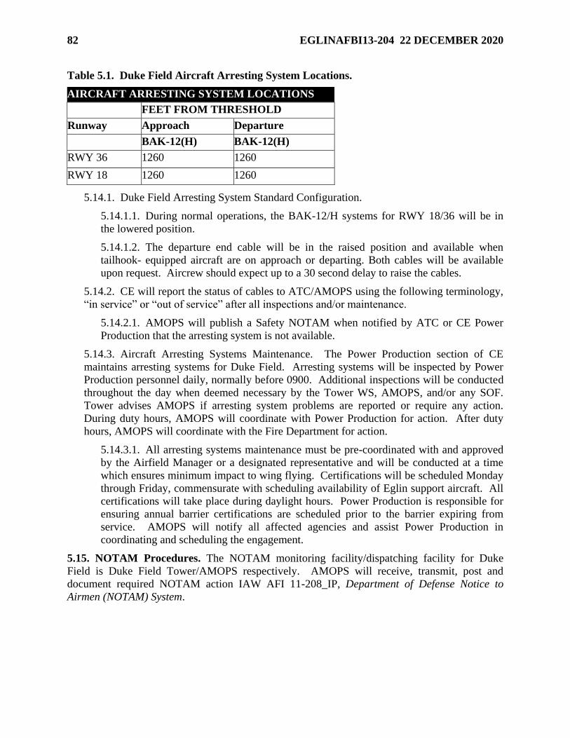
82 EGLINAFBI13-204 22 DECEMBER 2020
Table 5.1. Duke Field Aircraft Arresting System Locations.
AIRCRAFT ARRESTING SYSTEM LOCATIONS
FEET FROM THRESHOLD
Runway Approach Departure
BAK-12(H) BAK-12(H)
RWY 36 1260 1260
RWY 18 1260 1260
5.14.1. Duke Field Arresting System Standard Configuration.
5.14.1.1. During normal operations, the BAK-12/H systems for RWY 18/36 will be in
the lowered position.
5.14.1.2. The departure end cable will be in the raised position and available when
tailhook- equipped aircraft are on approach or departing. Both cables will be available
upon request. Aircrew should expect up to a 30 second delay to raise the cables.
5.14.2. CE will report the status of cables to ATC/AMOPS using the following terminology,
“in service” or “out of service” after all inspections and/or maintenance.
5.14.2.1. AMOPS will publish a Safety NOTAM when notified by ATC or CE Power
Production that the arresting system is not available.
5.14.3. Aircraft Arresting Systems Maintenance. The Power Production section of CE
maintains arresting systems for Duke Field. Arresting systems will be inspected by Power
Production personnel daily, normally before 0900. Additional inspections will be conducted
throughout the day when deemed necessary by the Tower WS, AMOPS, and/or any SOF.
Tower advises AMOPS if arresting system problems are reported or require any action.
During duty hours, AMOPS will coordinate with Power Production for action. After duty
hours, AMOPS will coordinate with the Fire Department for action.
5.14.3.1. All arresting systems maintenance must be pre-coordinated with and approved
by the Airfield Manager or a designated representative and will be conducted at a time
which ensures minimum impact to wing flying. Certifications will be scheduled Monday
through Friday, commensurate with scheduling availability of Eglin support aircraft. All
certifications will take place during daylight hours. Power Production is responsible for
ensuring annual barrier certifications are scheduled prior to the barrier expiring from
service. AMOPS will notify all affected agencies and assist Power Production in
coordinating and scheduling the engagement.
5.15. NOTAM Procedures. The NOTAM monitoring facility/dispatching facility for Duke
Field is Duke Field Tower/AMOPS respectively. AMOPS will receive, transmit, post and
document required NOTAM action IAW AFI 11-208_IP, Department of Defense Notice to
Airmen (NOTAM) System.
EGLINAFBI13-204 22 DECEMBER 2020 83
5.15.1. All flying squadrons will obtain their required NOTAMs through the FAA NOTAM
manager site (https://www.notams.aim.faa.gov). In the event the NOTAM web sites are
not operational, contact the destination airport via telephone to obtain the most current
NOTAMs. Contact Duke Field AMOPS at COMM: (850) 883-6516 or 6093/DSN: 875-
6516 or via direct line to obtain local NOTAMs. Hurlburt Field AMOPS will disseminate or
dispatch NOTAMs as required for Duke Field if the communication link to the Air Force
Central NOTAM facility is locally inoperative.
5.16. Airfield Maintenance. All airfield maintenance (e.g., all sweeper operations, grass
mowing, and general maintenance operations in the airfield environment) will be coordinated
and directed through the Airfield Manager.
5.17. Airfield Tobacco Use Policy. There is no smoking on the airfield outside designated
tobacco use areas. For further guidance see AFI 40-102.
5.18. Wear of Hats. The Duke Field Airfield is designated as a no-hat area IAW the 96 TW
supplement to AFI 21-101, Aircraft and Equipment Maintenance Management.
5.19. Airfield Photography. Refer to Paragraph 4.19 for photography restrictions.
5.20. Scheduling and Flight Plan Procedures. IAW AFI 13-204V3, all aircraft departing Air
Force installations must have a flight plan on file (Stereo, VFR local, DD Form 175 or DD Form
1801) with AMOPS prior to departure. Flight plans must be filed in person unless there is an
approved LOA on file between Airfield Management and the user(s). All flight plans will be
maintained on file in accordance with Air Force RDS, Table 13-07, Rule 3.00.5.20.1. Aircrews
should refer to the latest approved LOA between the 96 OSS and their squadron.
5.21. Controlled Movement Area (CMA). Duke Tower is the controlling agency for all
ground traffic in the controlled movement areas. Duke Field’s CMA consists of RWY 18/36, the
LZ, overruns, portions of all taxiways inside the VFR hold lines for both landing surfaces to the
edge of the pavement, all grassy areas between the distance remaining markers and the runway
edge, and grassy areas approximately 225’ out from the edge of the LZ in line with the VFR hold
lines.
5.21.1. Duke Field Tower FM Nets (Ramp to Tower and Crash to Tower) are used solely for
communications in the CMA. Tower shall continuously monitor these nets during
vehicle/personnel operations in the CMA. Vehicles/personnel operating in the CMA shall
continuously monitor these Nets and may transmit as necessary to ensure the safety/care of
personnel and/or equipment within the CMA. Tower may terminate unnecessary radio
transmissions from vehicles/personnel that are no longer operating in the CMA to reduce
frequency congestion, IAW AFI 13-204V3.
5.21.2. No vehicle is authorized in, nor shall be approved to enter a CMA unless the vehicle
is radio-equipped (or escorted by a radio-equipped vehicle) and in direct two-way radio
contact with Duke Tower. All vehicles operating east of the main RWY will maintain radio
communication with Duke Tower at all times.
84 EGLINAFBI13-204 22 DECEMBER 2020
5.21.3. Vehicle Recall Procedures when Radio Communications Fail. In the event radio
contact is lost, vehicles/personnel will exit the runway and CMA immediately. Duke Tower
will use light gun signals to attempt vehicle contact in the event of radio failure. Duke Tower
may also attempt to indicate that radio contact has been lost by raising and lowering the
intensity level of the runway lights.
5.21.4. CMA Vehicle/Pedestrian Operations. All personnel are required to abide by the
responsibilities and procedures for operating on or near Duke Field airfield outlined in
EAFBI 13-213V2, Duke Field Airfield Driving Instruction.
5.22. Precision Approach Critical Area. When the ceiling is reported less than 800 ft or
visibility less than 2 SM, aircraft and vehicles shall not be allowed to operate within the ILS
critical area depicted in Attachment 20 unless approved and in radio contact with Duke Tower.
Aircraft and vehicles shall not transit the precision approach critical areas or proceed beyond the
INST hold lines when an aircraft executing an ILS approach is inside the final approach fix. All
vehicles will request permission from Duke Tower by radio to cross both the north and south
areas of perimeter road that intersect precision approach critical areas regardless of weather
conditions.
5.23. Engine Test/Run-Up Areas and Procedures. IAW AFI 11-218, Aircraft Operations and
Movement on the Ground, aircraft are required to contact Duke Tower prior to engine start. The
MOC will advise AMOPS of all engine runs with tail number and location. AMOPS will in-turn
notify Tower of the engine run with tail number and location. Engine runs outside airfield hours
will be conducted by LOA between the 96 OG and applicable user.
5.24. Procedures for Suspending, Opening and/or Closing the Runway. Duke Tower and
AMOPS have authority to suspend runway operations anytime there is an observed or reported
hazardous condition or situation. Only AMOPS has the authority to close or open the runway.
Appropriate NOTAMs will be sent for suspensions/closures of the runway that exceed 30
minutes.
5.25. Airfield Inspections/Checks. Airfield inspections and checks will be completed IAW
requirements and procedures outlined in AFI 13-204V3. AMOPS shall accomplish an airfield
check after the arrival or departure of any wide-body aircraft to mitigate FOD risk due to the
narrow width of RWY 18/36 and lack of shoulders on several taxiways. AMOPS conducting
night time lighting checks have priority over NVD operations.
5.26. Aircraft Towing Procedures. All aircraft tows will be coordinated through 919 MOC.
The 919 MOC will notify AMOPS of aircraft tows (from where/to where). AMOPS will in-turn
notify the Tower of aircraft tows (from where/to where). Tows outside airfield hours will be
conducted by Letter of Agreement between the 96 OG and applicable user.
5.27. Aeromedical Aircraft Arrival Procedures. Duke Tower shall notify AMOPS when
arriving aeromedical airlift aircraft reach 15 NM from the airport and relay any information
requested by the pilot.
5.28. Local Control Points. See EAFB procedures, Paragraph 4.30
5.29. Tower Visual Blind Spots. Duke Tower is not responsible for ground traffic operating in
those areas not visible from the tower.
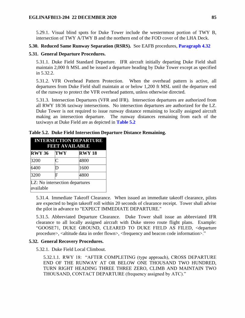
EGLINAFBI13-204 22 DECEMBER 2020 85
5.29.1. Visual blind spots for Duke Tower include the westernmost portion of TWY B,
intersection of TWY A/TWY B and the northern end of the FOD cover of the LHA Deck.
5.30. Reduced Same Runway Separation (RSRS). See EAFB procedures, Paragraph 4.32
5.31. General Departure Procedures.
5.31.1. Duke Field Standard Departure. IFR aircraft initially departing Duke Field shall
maintain 2,000 ft MSL and be issued a departure heading by Duke Tower except as specified
in 5.32.2.
5.31.2. VFR Overhead Pattern Protection. When the overhead pattern is active, all
departures from Duke Field shall maintain at or below 1,200 ft MSL until the departure end
of the runway to protect the VFR overhead pattern, unless otherwise directed.
5.31.3. Intersection Departures (VFR and IFR). Intersection departures are authorized from
all RWY 18/36 taxiway intersections. No intersection departures are authorized for the LZ.
Duke Tower is not required to issue runway distance remaining to locally assigned aircraft
making an intersection departure. The runway distances remaining from each of the
taxiways at Duke Field are as depicted in Table 5.2
Table 5.2. Duke Field Intersection Departure Distance Remaining.
INTERSECTION DEPARTURE
FEET AVAILABLE
RWY 36 TWY RWY 18
3200 C 4800
6400 D 1600
3200 F 4800
LZ: No intersection departures
available
5.31.4. Immediate Takeoff Clearance. When issued an immediate takeoff clearance, pilots
are expected to begin takeoff roll within 20 seconds of clearance receipt. Tower shall advise
the pilot in advance to "EXPECT IMMEDIATE DEPARTURE."
5.31.5. Abbreviated Departure Clearance. Duke Tower shall issue an abbreviated IFR
clearance to all locally assigned aircraft with Duke stereo route flight plans. Example:
“GOOSE71, DUKE GROUND, CLEARED TO DUKE FIELD AS FILED, <departure
procedure>, <altitude data in order flown>, <frequency and beacon code information>.”
5.32. General Recovery Procedures.
5.32.1. Duke Field Local Climbout.
5.32.1.1. RWY 18: “AFTER COMPLETING (type approach), CROSS DEPARTURE
END OF THE RUNWAY AT OR BELOW ONE THOUSAND TWO HUNDRED,
TURN RIGHT HEADING THREE THREE ZERO, CLIMB AND MAINTAIN TWO
THOUSAND, CONTACT DEPARTURE (frequency assigned by ATC).”
86 EGLINAFBI13-204 22 DECEMBER 2020
5.32.1.2. RWY 36: “AFTER COMPLETING (type approach), CROSS DEPARTURE
END OF THE RUNWAY AT OR BELOW ONE THOUSAND TWO HUNDRED,
TURN LEFT HEADING THREE THREE ZERO, CLIMB AND MAINTAIN TWO
THOUSAND, CONTACT DEPARTURE (frequency assigned by ATC).”
5.32.2. Light Aircraft Rectangular Pattern. Light aircraft pattern is 700 ft MSL with a 45-
degree entry to downwind. See Attachment 26.
5.32.2.1. RWY 18 will use right/left traffic.
5.32.2.2. RWY 36 will use right/left traffic.
5.32.3. Overhead Pattern. The overhead pattern altitude is 1,700 ft MSL. See Attachment
27.
5.32.3.1. RWY 18. Left or right entry; right turns.
5.32.3.2. RWY 36. Left or right entry; left turns.
5.32.4. Tactical Initial/Chase Aircraft. Tactical initial request shall be made on initial
contact with Duke Tower. Duke Tower has the authority to approve or deny this request. If
denied, aircraft must be no further than 500 ft separation prior to reaching the 3 NM initial
point. If tactical initial is approved, aircraft will remain no further than 4,000 ft line abreast
with the flight lead lined up on runway in use with the wingman lined up on the east side or
west side based on LZ traffic. When approved, Duke Tower will deconflict tactical initials
with LZ operations. When required due to traffic, flights with a chase aircraft may be
requested by Duke Tower to position chase aircraft offset to the west of the runway in use to
deconflict with LZ traffic.
5.32.5. VFR Straight-in. Duke Tower will approve VFR Straight-in approaches based on
traffic. Duke Tower will direct entry to final. A request by an IFR aircraft to land on the
LZ 18/36 is considered a request to automatically cancel IFR and conduct a VFR LZ
18/36 approach. Duke Tower will notify ERCF of aircraft’s IFR cancellation. Aircraft
established in Duke Tower’s VFR patterns requesting VFR straight-in approaches to RWY
18 will not extend beyond 3.5 NM north of RWY 18 to remain south Interstate 10 (I-10). If
aircraft requires to extend north of I-10, aircraft will transfer to ERCF for VFR flight
following. Aircraft requesting VFR straight-in approach to RWY 36 will not extend beyond
3.5 NM south of RWY 36. If aircraft requires to extend south of 3.5 NM, Duke Tower will
request and receive approval from ERCF and/or Eglin Tower based on pattern (east side/west
side) flown. VFR straight-ins beyond 3.5 NM may be disapproved based on ERCF and/or
Eglin Tower traffic.
5.32.6. Reentries. Reentry is used for re-sequencing and spacing requirements. The radio
call for reentries is “(Call sign), REENTER”.
5.32.6.1. The standard reentry point for RWY 18 is SHOAL (DWG 350/13.4). Reentry
pattern altitude is 2,200 ft MSL. Aircraft will maintain 2,200 ft MSL until established at
3 NM initial, unless otherwise directed by Duke Tower. Aircraft performing straight-in
approaches can expect descent to 1,200 ft MSL once established at SHOAL. Straight-in
approaches may be disapproved based on existing traffic.
EGLINAFBI13-204 22 DECEMBER 2020 87
5.32.6.2. The standard reentry point for RWY 36 is BIG T (DWG 340/8.6). Reentry
pattern altitude is 2,200 ft MSL. Aircraft will maintain 2,200 ft MSL until established at
3 NM initial, unless otherwise directed by Duke Tower. Aircraft performing straight-in
approaches can expect descent to 1,200 ft MSL once established at BIG T. Straight-in
approaches may be disapproved based on existing traffic.
5.32.7. Breakouts/Go Around Procedures.
5.32.7.1. VFR Procedures. VFR aircraft instructed by Duke Tower to breakout will be
given specific instructions [e.g., “(Call sign), BREAKOUT TO THE WEST, MAINTAIN
ONE THOUSAND SEVEN HUNDRED, REENTER INITIAL RUNWAY ONE
EIGHT”].
5.32.7.2. IFR Procedures. Aircraft at Duke shall use the following go-around procedures
unless otherwise directed by ATC:
5.32.7.3. Duke Go-Around Procedures inside 3 NM. ATC phraseology shall be as
follows: “Tower clearance canceled/not received, fly runway heading, CROSS
DEPARTURE END OF THE RUNWAY AT OR BELOW ONE THOUSAND TWO
HUNDRED, TURN (left/right) HEADING THREE THREE ZERO, CLIMB AND
MAINTAIN TWO THOUSAND.”
5.32.7.3.1. RWY 18: TURN RIGHT.
5.32.7.3.2. RWY 36: TURN LEFT.
5.32.7.4. Duke Go-Around Procedures outside 3 NM. ATC phraseology shall be as
follows: “(Call sign), BREAKOUT, TURN (left/right) HEADING THREE THREE
ZERO, CLIMB AND MAINTAIN TWO THOUSAND.”
5.32.8. VFR Fixed-Wing Tower to Tower Transitions between Eglin and Duke Towers.
Duke Tower Runway in Use will direct the inbound and outbound VFR transition routes.
Reference Attachments 12, 13, 14, and 15.
5.32.8.1. South Flow Operations (EGI RWY 18 and VPS RWY 12/19). See
Attachment 12.
5.32.8.1.1. VPS RWY 12/19 VFR departures tower to tower to EGI proceed
northbound to JAIL at 2,200 ft MSL then proceed to SHOAL at 2,200 ft MSL.
Eglin Tower will specify a left or right turn northbound. Once established at
SHOAL, turn 90 eastward to initial and expect overhead pattern altitude of 1,700 ft
MSL at 3 NM initial or descent for VFR straight-in with Duke Tower approval.
5.32.8.1.2. EGI RWY 18 VFR departures tower to tower to VPS proceed southbound
to JAIL at 1,600 ft MSL for Eglin Tower pattern entry.
5.32.8.2. North Flow Operations (EGI RWY 36 and VPS RWY 1/30). See Attachment
13.
5.32.8.2.1. VPS RWY 1/30 VFR departures tower to tower to EGI proceed
northbound to GATE at 1,700 ft MSL then direct to initial or straight-in RWY 36.
Expect overhead pattern altitude of 1,700 MSL at 3 NM initial or descent for VFR
straight-in with Duke Tower approval.
88 EGLINAFBI13-204 22 DECEMBER 2020
5.32.8.2.2. EGI RWY 36 VFR departures tower to tower to VPS proceed southwest-
bound to JAIL at 2,200 ft MSL for Eglin Tower pattern entry. Expect to cross the
field at 2,100 ft MSL for a left turn to initial.
5.32.8.3. Mixed Flow Operations (EGI RWY 18 and VPS RWY 1/30). See Attachment
14.
5.32.8.3.1. VPS RWY 1/30 VFR departures tower to tower to EGI proceed
northbound to JAIL at 2,200 ft MSL then proceed to SHOAL at 2,200 ft MSL. Once
established at SHOAL, turn 90 eastward to initial and expect overhead pattern
altitude of 1,700 ft MSL at 3 NM initial or descent for VFR straight-in with Duke
Tower approval.
5.32.8.3.2. EGI RWY 18 VFR departures tower to tower to VPS proceed southwest-
bound to JAIL at 1,600 ft MSL for Eglin Tower pattern entry.
5.32.8.4. Mixed Flow Operations (EGI RWY 36 and VPS RWY 12/19). See
Attachment 15.
5.32.8.4.1. VPS RWY 12/19 VFR departures tower to tower to EGI proceed
northbound to GATE at 1,700 ft MSL then proceed to EGI RWY 36. Eglin Tower
will specify a left or right turn northbound.
5.32.8.4.2. EGI RWY 36 VFR departures tower to tower to VPS will proceed
southwest-bound to JAIL at 2,200 ft MSL for Eglin Tower pattern entry.
5.32.9. Aircraft Taxi Procedures. Aircraft will change to Duke Ground Control frequency
after exiting the runway or landing zone surface. All aircraft shall:
5.32.9.1. Monitor Duke Ground Control frequency and give way to aircraft taxiing on
Taxiway alpha and emergency response vehicles, and taxi toward their parking locations.
5.32.9.2. Notify Ground Control before changing to another radio frequency while
taxiing unless switching to Duke Tower frequency for departure.
5.33. SFO and PFO Approaches. The terms PFO and SFO are synonymous and will utilize
the same approach patterns. SFO approaches will be conducted between the hours of sunrise to
sunset. To the maximum extent possible, SFOs shall be requested prior to RTB due to the
increased coordination required. In addition, Duke Tower may disapprove or cancel the
procedure whenever they deem it necessary for safety of flight. Approval of an SFO by Duke
Tower does not absolve the pilot from the responsibility to comply with VFR see and avoid
requirements. Participating aircraft are considered to have canceled IFR upon communications
transfer to Duke Tower. SFO airspace is defined as a 4 NM radius from center of the airport
from surface up to and including 10,000 ft MSL unless otherwise coordinated.
5.33.1. Weather and Runway Requirements. Official reported weather at the airport to
which the approach is conducted will be ceiling at least 1,000 ft above the requested high or
low key altitude and visibility of at least 5 SM.
5.33.2. Duke Field is the primary choice for SFO training based on traffic pattern congestion
at Eglin. Every attempt should be made to conduct SFO practice approaches to Duke Field.
5.33.3. SI SFO primary location is Duke Field RWY 18.
EGLINAFBI13-204 22 DECEMBER 2020 89
5.33.4. OH SFO Pattern Procedures. See Attachment 10.
5.33.4.1. RWY 18/36 OH SFO Procedures: From low approach or initial straight
through an aircraft will make a climbing turnout to the west or as directed by Duke
Tower and report high key when over the desired touchdown point in order to execute a
360-degree turning SFO to the west. If required to orbit at high key, Duke Tower will
state, “(callsign) ORBIT HIGH KEY”; the aircraft will maintain a western orbit at high
key altitude and report high key when over the desired touchdown point.
5.33.4.1.1. Additional information:
5.33.4.1.2. High Key will normally be flown at 7,000-10,000 ft MSL; other altitudes
may be coordinated.
5.33.4.1.3. Low Key will normally be flown at 3,000-6,000 ft MSL.
5.33.4.1.4. Airspeed will normally be 200 to 250 KIAS, but may vary due to weight
and aircraft configuration. Pilots requiring a speed in excess of 250 KIAS will notify
ATC prior to commencing the approach.
5.33.4.1.5. Mandatory reporting points: High Key and Low Key (with gear and
intentions).
5.33.4.1.6. The OH SFO pattern will be flown in the same direction as the normal
overhead pattern unless specified by tower.
5.33.4.1.7. OH SFO breakout procedures. Prior to base key, tower shall state “(Call
sign), REENTER, (Reason, time permitting, and follow-on instructions).” Aircraft
shall climb to or maintain 500 ft above the overhead pattern altitude and comply with
tower instructions. If none are received, transmit intentions to Duke Tower.
5.33.4.1.8. OH SFO Go-Around procedures. Tower shall state “(Call sign), GO
AROUND, (Reason, time permitting, and follow-on instructions).” If at or above
2,200 ft MSL, maintain 2,200 ft MSL (500 ft above overhead pattern). If below
2,200 ft MSL the aircraft will continue to descend to maintain at or below 1,200 ft
MSL until departure end, and comply with tower instructions. If none are received,
transmit intentions and requests to tower.
5.33.4.1.9. For a pilot-initiated go-around or when a landing clearance is not
received, the pilot shall report “(Call sign), BASE KEY, ON THE GO.” Execute the
go-around procedure described above and follow tower instructions. If no
instructions are received, the pilot shall transmit intentions to Duke Tower in the
blind.
5.33.4.1.10. If weather does not allow the execution of an SFO initiated from High
Key, Tower can authorize SFOs initiated from Low Key based on current weather
conditions and aircraft workload within the traffic pattern. The same ground track
will be flown as described above, while remaining clear of clouds.
5.33.5. SI SFO Pattern Descriptions and Procedures. See Attachment 10.
5.33.5.1. An SI SFO approach begins 8 NM from the runway and ends at the landing
threshold.
90 EGLINAFBI13-204 22 DECEMBER 2020
5.33.5.2. The 8 NM SI SFO point is straight out from the runway extended centerline at
8,000 ft MSL.
5.33.5.3. The 5 NM SI SFO point is straight out from the runway extended centerline at
4,000 to 6,000 ft MSL.
5.33.5.4. SI SFO airspeed will normally be 200 to 250 KIAS, but may vary due to weight
and aircraft configuration. Pilots requiring a speed in excess of 250 KIAS will notify
ATC prior to commencing the approach.
5.33.5.5. If ERCF traffic permits, SI SFOs can expect descent to 8,000 ft MSL and
vectors to the 8 NM reporting point. ERCF will coordinate with tower for SI SFO
approval. Tower will deny the approach if more than three aircraft are projected to be in
the VFR pattern when the SI SFO will arrive, or if a safety issue is involved.
5.33.5.6. If tower approval is not received by 20 NM from the runway, expect descent to
pattern altitude and sequencing with normal arriving traffic. If tower approval is received
by the 20 NM point, expect a vector to a point 12-14 NM on final/dogleg, instructions to
proceed visually, and to contact Duke Tower. At this point, IFR flight plan cancellation
is deemed to have occurred. Communications transfer to Duke Tower must occur prior
to commencing the SI SFO maneuver. After contact with tower, and prior to 8 NM on
final, expect verbal approval for the SI SFO from tower. If conditions develop which
preclude the approach, expect to be sequenced by Duke Tower into the overhead pattern.
If unable to communicate with Duke Tower, maintain 8,000 ft MSL and VFR, fly toward
the runway and contact ERCF on last assigned ERCF frequency.
5.33.5.7. Mandatory reporting points: Report: “(Call sign), 8-MILE SFO FINAL” and
“(Call sign), 5-MILE SFO FINAL, GEAR, and intentions (e.g., touch and go, low
approach)” to tower. Expect low approach clearance at 5 NM. If clearance is not
received by 3 NM on final, proceed straight ahead, maintain 2,200 ft MSL (500 ft above
the overhead pattern), and expect an overhead approach.
5.33.5.8. If tower does not have a visual or radar-indicated position of the aircraft by 5
NM final, tower will discontinue the SI SFO approach and give directions to sequence
the aircraft into the overhead pattern.
5.33.5.9. Once the SI SFO aircraft is 8 NM final or closer, no arrival or departure aircraft
will be permitted in front of the SI SFO aircraft.
5.33.5.10. SI SFO Breakout/Go-Around Procedures.
5.33.5.10.1. Prior to 5 NM final the tower shall state “(Call sign), TERMINATE
THE SI-SFO, (Reason, time permitting, and follow-on instructions).” If no
instructions are received, climb to or maintain 2,200 ft MSL (500 ft above the
overhead pattern), and expect an overhead approach.
5.33.5.10.2. Pilot initiated/tower directed go-around at or after 5 NM final. If at or
above 2,200 ft MSL, maintain 2,200 ft MSL (500 ft above overhead pattern). If
below 2,200 ft MSL the aircraft will continue to descend to maintain at or below
1,200 ft MSL until departure end, and comply with tower instructions. If none are
received, transmit intentions to Duke Tower.
EGLINAFBI13-204 22 DECEMBER 2020 91
5.33.6. F-35 aircraft may perform PFOs using the SFO patterns at Eglin and Duke Field.
For the purposes of this instruction, PFO and SFO are synonymous. However, expect
slightly higher altitudes and airspeeds at high key and low key, and a slightly extended
pattern at low key. Controllers and pilots will use the term PFO when referring to an F-35 in
the SFO pattern (e.g., "LIGHTNING-01, 8-MILE PFO FINAL").
5.34. Duke Field Random Steep Approach. The Random Steep Approach is a VFR maneuver
that consists of a steep spiral descent, similar to an overhead approach, from higher than normal
traffic pattern altitudes directly over the airport. Aircraft will remain within a 4 NM radius of
Duke Field during descent. Approval for Random Steep Approach is at the discretion of the
Duke Tower WS after coordination with ERCF. Random Steep Approaches may be disapproved
or canceled because of traffic or for other reasons, either before or after the start of the
maneuver. Approval of a Random Steep Approach does not relieve the pilot from the
responsibility to comply with VFR see and avoid requirements. Participating aircraft are
considered to have canceled IFR upon communications transfer to Duke Tower.
5.34.1. Weather and Landing Surface Requirements. Random Steep Approaches may be
conducted to RWY 18/36 or LZ 18/36. Official reported weather at Duke Field to conduct a
Random Steep Approach will be:
5.34.1.1. Ceiling: At least 500 ft above the requested inbound altitude.
5.34.1.2. Visibility: At least 3 SM visibility. Aircraft must maintain VFR cloud
clearance throughout the maneuver.
5.34.2. Random Steep Approach Pattern Descriptions and Procedures. See Attachment 29.
5.34.2.1. ERCF will coordinate with Duke Tower for Random Steep Approach approval
prior to the aircraft reaching 10 NM. Coordination will include callsign, type aircraft,
aircraft location, requested altitude and inbound heading (180, 360, 270, or 090). ERCF
will release Duke Field Random Steep Approach maneuvering airspace to Duke Tower.
Communications transfer to Duke Tower must occur prior to 5 NM from the descent
point. Inbound altitude will vary based on pilot’s request (normally 4,500-10,000 ft
MSL). Aircraft airspeed is normally 120-150 KIAS. Inbound heading is normally in line
with runway in use. Other inbound headings may be requested. Approval will be based
on traffic. Descent point is normally at the midfield point. At descent point, aircraft will
report landing gear down and request landing clearance from Duke Tower. Based on
aircraft altitude, aircraft may spiral in descent east and west of runway to land on runway
in use. If conditions develop which preclude the completion of the approach, aircraft can
expect to be sequenced by tower into either the overhead pattern or rectangular traffic
pattern. Aircraft requesting Random Steep Approaches from the Duke rectangular VFR
pattern or initial departure will normally be transferred to ERCF for climb to Random
Steep Approach altitude unless ERCF releases Random Steep Approach maneuvering
airspace to Duke Tower. Once Random Steep Approach maneuvering airspace is
released to Duke Tower, ERCF will not allow other aircraft to transit the maneuvering
airspace.
92 EGLINAFBI13-204 22 DECEMBER 2020
5.35. Duke Field Random Shallow Approach. Random Shallow Approach is a VFR
maneuver that consists of low-altitude/high-speed entry towards the runway from various
inbound headings.
5.35.1. The Random Shallow Approach will be approved at the discretion of the Duke
Tower WS. Random Shallow Approaches may be disapproved or canceled because of traffic
or for other reasons, either before or after the start of the maneuver. Approval of a Random
Shallow Approach does not relieve the pilot from the responsibility to comply with VFR see
and avoid requirements and AFI 11-202V3, General Flight Rules, avoidance criteria.
Participating aircraft are considered to have canceled IFR upon communications transfer to
Duke Tower.
5.35.2. The three types of Random Shallow Approaches are as follows:
5.35.2.1. 90-degree to the runway abeam. The aircraft flies to the runway’s midfield
point, then performs a 90-degree turn for a downwind entry to the runway in use.
5.35.2.2. Straight-in to the active runway with a teardrop maneuver to land the opposite
runway. Similar to a circling approach.
5.35.2.3. Straight-in to the active runway. Aircraft performs a straight-in approach to the
runway in use.
5.35.3. Weather and Landing Surface Requirements. Random Shallow Approaches may be
conducted to RWY 18/36 or LZ 18/36. Official reported weather at Duke Field to conduct a
Random Shallow Approach will be:
5.35.3.1. Ceiling: At least 500 ft above the rectangular pattern altitude.
5.35.3.2. Visibility: At least 3 SM visibility. Aircraft must maintain VFR cloud
clearance throughout the maneuver.
5.35.4. Random Shallow Approach Pattern Descriptions and Procedures. See Attachment
29.
5.35.4.1. ERCF will coordinate with Duke Tower for aircraft RTB to Duke Field for
Random Shallow Approach prior to 10 NM. Coordination will include callsign, type
aircraft, aircraft location, and type of Random Shallow Pattern requested (abeam,
teardrop, or straight-in). All approaches will be made to the runway in use unless
previously coordinated. Aircraft in the Duke VFR pattern who request Random Shallow
Approach from Duke Tower will remain within a 4 NM radius of Duke Field and in radio
contact with Duke Tower at all times. East entries will be approved by ERCF on a case-
by-case basis due to the proximity of Eglin’s RWY 19 final approach course.
Communications transfer to Duke Tower must occur prior to entering Duke Field’s Class
D airspace (5.2 NM radius of the geographical center of Duke Field). Inbound altitude
will be 1,200 ft MSL or higher. Once inside Duke Tower’s Class D airspace, aircraft
may descend to 500 ft AGL (IAW AFI 11-202V3) to perform the maneuver. Aircraft
will avoid over flying populated areas. Aircraft initial airspeed is normally 250 KIAS. If
conditions develop which preclude the completion of the approach, aircraft can expect to
climb to 1,200 ft MSL and be sequenced by Duke Tower into the rectangular traffic
pattern.
EGLINAFBI13-204 22 DECEMBER 2020 93
5.36. VFR NVD Operations: Duke Field VFR NVD operations apply only to 919/492 SOW,
96 TW, and 1 SOW, and any units temporarily assigned under OPCON to these units. The
following procedures are IAW AFI 13-204V3. No IFR approach NVD procedures exist for
Duke Field. Base assigned NVD qualified aircrews may depart/arrive VFR under NVDs if the
airfield runway lights/taxiway lights are out of service. Note; a NOTAM will be published for
the affected lighting system out of service.
5.36.1. NVD Taxi Routes. All taxiways, aprons, both VL Pads, the LHA Deck, and LHA
FOD cover are approved NVD routes for qualified aircrews attached to the units listed above.
NVD taxi routes are standard for the runway in use.
5.36.2. NVD Vehicle Operations. Duke Airfield Management is authorized to drive within
the Duke Airfield CMA wearing NVDs. Airfield Management may only use NVDs while
conducting a lighting check of the IR lights on the LZ. All units that have the operational
requirement to drive on the airfield while using NVDs are required to establish a training
plan outlined in AFMAN 24-306 Chapter 18 and AFI 13-213 Paragraph 3.2.7.22 Units will
coordinate with the Duke Airfield Wing Airfield Driving Program manager to establish a
LOA that outlines all the procedures.
5.36.3. NVD VFR Traffic Patterns. NVD traffic patterns are coincidental with the standard
VFR traffic patterns for the runway in use and standard VFR pattern position reports are
required. Request for NVD airfield light settings (AMP 3 or AMP 4) and appropriate step
settings will be made on initial contact with Duke Tower and prior to turning base. A
request by an IFR aircraft to conduct NVG operations is considered a request to
automatically cancel IFR. Duke Tower will notify ERCF of aircraft’s IFR cancellation.
The maximum number of aircraft simultaneously performing NVD operations is five, not to
include aircraft operating in the VETA (See Paragraph 5.6.4.6). Duke Tower may reduce
this number based on safety of flight. VFR straight-in approaches to RWY 36 will be
approved based on traffic. Aircraft requesting 10 NM straight-in VFR finals for RWY 18
will ensure the final approach course is at least 2 NM east of CEW airport to avoid CEW
RWY 17/35 departures/arrivals. Altitude for VFR straight-in approaches is at or above 1,000
ft AGL. Aircraft will be switched to ERCF for flight following based on CEW traffic.
Aircraft will monitor CEW CTAF on 122.95 when in the vicinity of CEW airport and
maintain maximum vigilance for CEW traffic. All aircraft require Duke Tower approval to
cross RWY 18/36 final approach course.
5.36.4. Transition to Normal Lighting Configuration for Nonparticipating Aircraft.
Nonparticipating aircraft will not mix with participating NVD aircraft in any traffic pattern,
on any controlled movement area, or when taxiing. When transitioning to normal airfield
lighting configuration for non-participating arriving aircraft, the airfield lights will be
configured prior to the nonparticipating aircraft entering the Class D airspace. For
nonparticipating departures, normal airfield lighting will be utilized prior to the
nonparticipating aircraft taxi.
5.36.5. Emergency Termination/Knock it Off Procedures. Duke Tower or aircrew may
terminate NVD operations whenever safety of flight becomes an issue.
94 EGLINAFBI13-204 22 DECEMBER 2020
Chapter 6
EMERGENCY PROCEDURES
6.1. Daily Primary Crash Alarm System (PCAS) Phone Check. A quality assurance check
of the Eglin crash phone shall be performed daily, normally between 0700L and 0730L. The
quality assurance check of the Duke Field crash phone shall be performed daily prior to opening
Duke Tower.
6.2. Emergency Notification. In order to expedite the activation and movement of emergency
response agencies/vehicles, pilots shall declare an emergency with ATC as soon as possible
when a situation in the aircraft commander’s judgment warrants response from emergency
response agencies or when the aircraft has hung Category I (Cat I) or hung developmental
ordnance.
6.3. Arrival/Departures. No aircraft should be allowed to land on or takeoff from the same
runway after an inbound emergency aircraft is within 10 NM (fighter aircraft) or within 5 NM
(all other aircraft).
6.4. Eglin/Duke Field Discrete Emergency Frequency. The Eglin/Duke Field discrete
emergency frequency is local channel 9/269.15. The purpose of this discrete frequency is to
provide ATC, Eglin SOF, and Eglin/Duke Field Fire Department Crash or on-scene commander
with a single frequency to handle aircraft emergencies. Eglin/Duke Field Towers shall announce
over the PCAS if the emergency aircraft is on a frequency other than local channel 9/269.15.
Simulcasting on local channel 9/269.15 or any discrete frequency assigned to an emergency
aircraft is prohibited. All transmissions to the emergency aircraft shall be pertinent to the
emergency.
6.5. In-Flight/Ground Emergency Responsibilities/Procedures.
6.5.1. Eglin and Duke Field Towers shall:
6.5.1.1. Activate the PCAS when any of the following occur:
6.5.1.1.1. Any known or suspected crash involving an aircraft operating within
ERCF, Eglin Tower, or Duke Tower assigned airspace.
6.5.1.1.2. All emergency landings.
6.5.1.1.3. All unescorted lost communications aircraft.
6.5.1.1.4. All observed or reported ground emergencies.
6.5.1.1.5. Aircraft reporting hot brakes.
6.5.1.1.6. Aircraft landing with hung Cat I or hung developmental ordnance.
6.5.1.1.7. Pilot request.
6.5.1.1.8. When deemed necessary by the WS/SC or Eglin SOF. NOTE: The PCAS
should be reactivated any time there are significant changes to an existing situation
that may warrant it.
EGLINAFBI13-204 22 DECEMBER 2020 95
6.5.1.2. Advise AMOPS at least 15 minutes prior, or as soon as possible, any time the
pilot of an emergency aircraft requests Eglin Boulevard and Memorial Trail traffic be
stopped for an emergency landing. See Chapter 7 of this instruction for Hung Ordnance
procedures.
6.5.1.3. Broadcast the following on ground control frequencies, Ramp Net, and Crash
Net: “THIS IS EGLIN/DUKE GROUND WITH AN EMERGENCY RECOVERY IN
PROGRESS, GIVE WAY TO ALL RESPONDING EMERGENCY VEHICLES AND
EVACUATE ALL ATCALS FACILITIES.”
6.5.1.4. Advise responding emergency teams of the appropriate frequency during a
ground emergency or when multiple emergencies occur.
6.5.1.5. Instruct the pilot to contact Chief-2 or the Incident Commander after the
emergency aircraft has landed and no further ATC communications are necessary.
Example: “(Call sign), WHEN ABLE, CONTACT CHIEF TWO/INCIDENT
COMMANDER THIS FREQUENCY.”
6.5.1.6. Monitor communications through termination of the emergency.
6.5.2. AMOPS Responsibilities:
6.5.2.1. Activate the Secondary Crash Net (SCN) in response to information received via
the primary crash net.
6.5.2.2. When required, Eglin AMOPS shall advise the 96th Security Forces Squadron
(96 SFS) to stop traffic on Eglin Boulevard and Memorial Trail for an emergency
landing. The 96 SFS shall then take action as necessary. At Duke Field, Duke AMOPS
will request Security Forces close SR213 between the east and west security fences when
aircraft with hung ordnance are heading south.
6.5.3. Designation and responsibilities of the Incident Commander (On/Off Base).
6.5.3.1. EAFB will respond to disaster situations occurring on base or on AF-owned
property and assist the local civilian community in coping with disaster situations off
base, when requested.
6.5.3.2. The Incident Commander is designated IAW EAFB Plan 10-2, Installation
Emergency Management Plan, and EAFB Plan 91-204, Mishap Response Plan (FOUO).
The Incident Commander will designate the Entry Control Point (ECP) and serve until
the emergency/mishap site is declared safe.
6.5.3.3. The Incident Commander shall not initiate transmissions on local emergency
frequencies until contacted by ATC.
6.5.3.4. The Incident Commander shall notify the tower via the crash net when the
emergency is terminated. Any assigned discrete emergency frequency shall be returned
to ATC immediately after termination of the emergency.
6.6. Emergency Information.
6.6.1. Aircraft shall provide ATC with the following initial information when an emergency
is declared (time permitting):
6.6.1.1. Call sign (identification).
96 EGLINAFBI13-204 22 DECEMBER 2020
6.6.1.2. Type aircraft.
6.6.1.3. Nature of emergency.
6.6.1.4. Pilot’s intentions.
6.6.2. After an emergency notification, ATC will relay the following items or any other
pertinent information over the PCAS.
6.6.2.1. Call sign (identification).
6.6.2.2. Type aircraft.
6.6.2.3. Nature of emergency.
6.6.2.4. Pilot’s intentions.
6.6.2.5. Number of personnel on board.
6.6.2.6. Fuel remaining.
6.6.2.7. Landing runway, wind, and Estimated Time of Arrival (ETA).
6.6.2.8. Emergency response requirements (example: approach end engagement, stop
boulevard traffic).
6.6.2.9. Ordnance type and number.
6.7. Emergency Locator Transmitters (ELT) and Crash Position Indicators (CPI).
6.7.1. An inadvertent activation of an ELT/CPI does not require an immediate response or
processing as an emergency. Unless a requirement for assistance is verified, the PCAS
should not be activated. NOTE: Operational ground testing of ELT/CPI has been
authorized during the first 5 minutes of each hour. To avoid confusing the tests with an
actual alarm, the testing is restricted to no more than three audio sweeps.
6.7.2. When Eglin Tower is notified or receives an ELT/CPI, other than during the first 5
minutes of the hour, they will notify the ERCF, Command Post, and AMOPS. The ERCF
will notify Jacksonville Center.
6.7.3. If ERCF is notified or receives an ELT/CPI other than during the first 5 minutes of the
hour, they will notify Eglin, Duke, and Hurlburt towers, Command Post, AMOPS, and
Jacksonville Center.
6.7.4. AMOPS will notify Tower, ERCF, and MOCC, if they receive ELT/CPI information
from another source.
6.7.5. If the ELT/CPI signal strength indicates the signal may be emanating from somewhere
on the airport, the MOCC will notify appropriate base personnel to attempt to determine if
the signal is emitting from the base survival equipment shop or a parked aircraft. If located,
inform AMOPS and they will inform tower and ERCF that the signal was located and/or
terminated.
6.7.6. ERCF will notify Jacksonville Center if signal source is located and/or terminated.
EGLINAFBI13-204 22 DECEMBER 2020 97
6.8. Beacon Code 7700 Response on the Ground. When a 7700 squawk is detected at
Eglin/Duke, the following actions shall apply:
6.8.1. ERCF shall notify tower with the suspected location/source, if known.
6.8.2. Tower personnel shall activate the PCAS and state the following: “WE ARE
RECEIVING SQUAWK 7700 ON THE GROUND AT EGLIN/DUKE.”
6.8.3. AMOPS shall relay the same message over the SCN.
6.8.4. The Eglin Command Post shall notify required agencies to locate the source.
6.8.5. The fire department shall respond to the area identified, but shall not block operations
to and from the area. They shall stand by in this advanced response state waiting for more
information on the nature of the emergency or until the squawk is declared inadvertent.
6.8.6. If it cannot be immediately determined that the 7700 squawk is inadvertent, tower
shall suspend all airfield operations.
6.8.7. The Incident Commander shall determine/terminate the response/emergency.
6.9. Runway Checks Following an Emergency.
6.9.1. The following personnel are authorized to perform runway checks after an emergency:
6.9.1.1. AMOPS.
6.9.1.2. 96 OG/CC or designated representative.
6.9.1.3. Eglin SOF.
6.9.1.4. Incident Commander/Senior Fire Officer.
6.9.1.5. 96 TW, 33 FW or 53 WG Safety.
6.9.2. Runway operations shall be suspended to the affected runway after an IFE or ground
emergency in order to allow AMOPS to check the runway. The Eglin SOF has the authority
to waive a runway check for those IFEs that are of a non-FOD producing nature (e.g., smoke
in the cockpit, sick crew member or passenger). The Tower WS may suspend taxiway
operations when a potential FOD hazard exists due to IFE recovery or when the on-scene
commander establishes a cordon around an emergency aircraft.
6.9.3. If the Eglin SOF determines to waive the runway check, then the SOF will call
AMOPS to advise “NO RUNWAY CHECK REQUIRED.” AMOPS will, in turn, document
in AF Form 3616, Daily Record of Facility Operation.
6.10. Aircraft Arresting System Procedures.
6.10.1. Should a cable engagement be made at any time during a landing when the pilot has
not declared intention to do so, it will be treated as an emergency.
6.10.2. Lost Communication Procedures. Plan the approach as dictated by the emergency.
Squawk 7600. While on final, monitor tower for light gun signals. Flashing your landing
light while on final will signify intent to engage a barrier.
6.10.3. Approximate successive cable engagement intervals are as follows:
6.10.3.1. BAK 12: 10 to 20 minutes.
98 EGLINAFBI13-204 22 DECEMBER 2020
6.10.3.2. MB-100: 4-hour minimum time to replace the one-time use textile brake
system.
6.10.3.3. E5: 60 minutes.
6.11. Fuel Dumping. Fuel dumping shall be coordinated with ATC and shall be conducted, to
the extent possible, over water or unpopulated land areas at an altitude at least 5,000 ft above the
highest obstacle.
6.12. External Stores/In-Flight Aircraft Cargo Jettison Procedures. When requested, the
ERCF may provide navigation assistance to an external stores/cargo jettison area. When
feasible, release of external stores or cargo shall be made over water or uninhabited land areas
(See Attachment 44) within the Eglin Range complex (preferably B-71) IAW Paragraph 7.5
Prior to release, if conditions permit, the aircraft commander will ensure the ground or water is
clear of personnel, vessels, or equipment and notify the controlling agencies of desired release
location.
6.13. MC-130 Refueling Hose Jettison Procedures.
6.13.1. MC-130 aircraft with a hung refueling hose shall jettison over the following ranges:
SONTAY DZ (R-2915A CEW 218/12), PINO DZ (R-2914A CEW 120/17), inactive ranges,
or Eglin water range.
6.13.2. If a hose fails to cut, avoid populated areas and make an approach to RWY 1, RWY
12, or RWY 30 at Eglin; RWY 18 or 36 at Duke Field; or RWY 18 at Hurlburt Field. Advise
ATC if a road should be closed for the approach.
6.14. Aircraft Abandonment/Controlled Bailout Procedures.
6.14.1. Controlled Conditions. To preclude the possibility of aircraft crashing into a
populated area in the Eglin complex after abandonment, the following procedures shall be
used when an aircraft can be flown and abandoned under controlled conditions:
6.14.1.1. Maintain VFR if practical. If unable to maintain VFR, request appropriate
control instruction from ERCF.
6.14.1.2. Notify applicable control agencies of intention to abandon aircraft. Eject/bail
out over land areas, if practical. Utilize the Eglin range complex (preferably B-71).
Eglin Approach Control/Mission Control will provide radar monitoring and furnish Eglin
and Duke Towers (for PCAS activation) the probable impact point of the aircraft or eject
point of the aircrew. ATC personnel will record the anticipated/suspected point of impact
on appropriate crash grid maps and pass location information to emergency responders.
6.14.1.3. Recommended Pilot Procedures:
6.14.1.3.1. Coordinate with the Eglin SOF.
6.14.1.3.2. Altitude: 5,000 ft MSL for Eglin.
6.14.1.3.3. Radial/DME 293/7 (CH 2) or 360/06 (CH 45).
6.14.1.3.4. Once established within B-71:
6.14.1.3.4.1. Heading: 320° for ejection.
6.14.1.3.4.2. Airspeed: As slow as practical.
EGLINAFBI13-204 22 DECEMBER 2020 99
6.14.1.3.4.3. Flight Controls: Trimmed for wings-level flight. No Sink rate.
6.14.1.3.4.4. Throttles: Idle prior to ejection.
6.14.2. Aircraft commanders may bail out crew members at any suitable predestinated area
prior to initiating the procedures outlined in this paragraph.
6.14.3. The areas shown in Attachment 44 should be used if possible when bailing out from
an aircraft in the traffic pattern in order to avoid populated areas.
6.15. Emergency Landing Gear Checks.
6.15.1. A pilot experiencing landing gear trouble shall be cleared to make a low pass by the
control tower for visual check of the landing gear. When passing the control tower, altitude
shall be at the pilot’s discretion, but no lower than 200 ft AGL.
6.15.2. Time permitting, the pilot may have the landing gear checked over the runway by the
Eglin SOF, a pilot proficient in that type of aircraft, a maintenance officer/chief, or AMOPS.
Comments of ground observers and information/assistance rendered by other qualified
aircraft in-flight are advisory in nature only. The pilot shall determine the final course of
action.
6.16. Hot Brakes Parking Areas. Pilots shall notify the Tower of hot brakes and parking
intentions. Tower personnel shall notify AMOPS via the PCAS, which shall then notify the
appropriate maintenance organization. Aircraft having hot brakes after landing or aborting
takeoff shall be parked on the following taxiways to the maximum extent possible:
6.16.1. EAFB (See Attachment 2):
6.16.1.1. RWY 1: TWY P.
6.16.1.2. RWY 19: TWY G-East.
6.16.1.3. RWY 12: TWY G-East, TWY V, or the revetted De-arm area at the
intersection of TWY B and TWY F.
6.16.1.4. RWY 30: TWY D-North, TWY C, or the revetted De-arm area at the
intersection of TWY B and TWY F.
6.16.2. Duke Field (See Attachment 20):
6.16.2.1. RWY 18: TWY E-West.
6.16.2.2. RWY 36: TWY B.
6.17. Hydrazine Leak Parking Areas. Pilots with a suspected hydrazine leak shall notify the
appropriate ATC agency as soon as possible. Tower shall notify AMOPS via the crash phone,
which shall then notify the appropriate maintenance organization. After landing, aircrew will
use judgment to determine whether to remain stationary or taxi to a designated hydrazine area
following EPU activation or suspected hydrazine leak. Designated hydrazine areas are as
follows:
6.17.1. EAFB (See Attachment 2):
6.17.1.1. RWY 1: TWY L, adjacent to HS-12 for daytime use only. (Aircraft shall use
TWY J- West after dark.)
100 EGLINAFBI13-204 22 DECEMBER 2020
6.17.1.2. RWY 19: TWY J-West, adjacent to HS-2.
6.17.1.3. RWY 12: TWY F-North.
6.17.1.4. RWY 30: TWY E-North.
6.17.2. Duke Field (See Attachment 20):
6.17.2.1. RWY 18/36: Apex of TWY D and F or VL South Pad, as dictated by Duke
AMOPS.
6.18. Alternate ATC Facility Procedures.
6.18.1. Tower Evacuation Procedures.
6.18.1.1. Eglin Tower: In the event of an Eglin Tower evacuation, tower operations will
be conducted from King Hangar, Bldg. 130. Due to the limited personnel and equipment
in the alternate facility, practice approaches will not be approved. In the event of an
evacuation of the primary control tower, Eglin Tower WS will:
6.18.1.1.1. Relay the information over landline to AMOPS for SCN activation.
6.18.1.1.2. Direct all ground vehicles to exit the runway/controlled movement area
and expect further directions when the alternate tower is operational.
6.18.1.1.3. Notify ERCF of the evacuation and request they monitor frequencies
353.65 and 118.2 and provide airport advisories until the alternate facility is
operational.
6.18.1.1.4. Activate the PCAS and state “EGLIN TOWER IS BEING EVACUATED
TO THE ALTERNATE CONTROL TOWER DUE TO (reason).” In addition, if
time permits, they will broadcast on all assigned frequencies “ALL AIRBORNE
AIRCRAFT CONTACT EGLIN APPROACH CONTROL ON (frequency). ALL
GROUND TRAFFIC HOLD YOUR POSITION AND STANDBY, EXPECT A
THREE ZERO MINUTE DELAY.”
6.18.1.1.5. When Tower is ready to resume operations from the alternate tower,
Tower will notify ERCF, assume control of any aircraft within their area of
jurisdiction, and activate the PCAS and broadcast on all assigned frequencies
"EGLIN TOWER HAS RESUMED OPERATION FROM THE ALTERNATE
CONTROL TOWER."
6.18.1.2. Duke Tower: In the event of Duke Tower evacuation, the ERCF shall provide
airport advisory service, monitor Duke Tower frequencies, and maintain communications
with aircraft until landing. No alternate fixed or mobile tower facility exists at Duke; all
airborne aircraft will be diverted.
6.18.1.2.1. Tower personnel will activate the PCAS and state “DUKE TOWER IS
BEING EVACUATED DUE TO (reason).” If time permits, they will broadcast on
all assigned frequencies “ALL AIRBORNE AIRCRAFT CONTACT EGLIN
APPROACH CONTROL ON (frequency). ALL GROUND TRAFFIC HOLD
YOUR POSITION AND STANDBY. CONTACT PILOT TO DISPATCH ON
(frequency) FOR INFORMATION.”
EGLINAFBI13-204 22 DECEMBER 2020 101
6.18.1.2.2. Notify ERCF of the evacuation and request they monitor Duke
frequencies and provide airport advisories until Duke Tower is ready to resume
operations.
6.18.1.2.3. When Duke Tower is ready to resume operations, and the opening
checklists are complete, the WS will notify ERCF/Eglin Tower, assume control of
any aircraft within their area of jurisdiction, and activate the PCAS and broadcast on
all assigned frequencies "DUKE TOWER HAS RESUMED OPERATIONS."
6.18.1.2.4. Wind Limitations on Eglin and Duke Towers. Personnel shall evacuate
Eglin Tower (primary) Eglin Alternate Tower, and Duke Tower Cab when sustained
winds are ≥ 60 knots and/or gusts ≥ 75 knots. When the reason for evacuation is for
winds or when Alternate Tower requires evacuation, Eglin Tower personnel will
evacuate to the ERCF. Duke Tower personnel will evacuate to the first floor of the
tower for weather phenomena.
6.18.2. ERCF Evacuation Procedures.
6.18.2.1. In the event of the ERCF evacuation, the ERCF shall accomplish the following
in addition to any checklist items established by the facility chief controller. Time
permitting, the ERCF shall attempt to coordinate and/or handoff all aircraft to the
appropriate facility prior to evacuation.
6.18.2.1.1. Immediately notify Jacksonville Center and Eglin Tower. Ensure tower
activates PCAS.
6.18.2.1.2. Instruct aircraft in the terminal area to contact the appropriate tower.
Instruct other aircraft to contact Jacksonville Center (ZJX).
6.18.2.1.3. Dispatch one supervisor and two qualified controllers to Eglin Tower
with the fly- away kit to provide conventional ATC.
6.18.2.1.4. Time permitting, notify Hurlburt Tower, Duke Tower, Pensacola
Approach, Tyndall Approach, Cairns Approach, Seabreeze, and Gainesville Flight
Service Station (FSS).
6.18.2.1.5. Broadcast on all available frequencies, including 121.5 and 243.0,
“ATTENTION ALL AIRCRAFT. EGLIN APPROACH CONTROL IS BEING
EVACUATED DUE TO (Reason). CONTACT JACKSONVILLE CENTER ON
(Frequency) FOR FURTHER INSTRUCTIONS.”
6.18.2.1.6. Broadcast on all assigned mission frequencies, “ATTENTION ALL
AIRCRAFT. EGLIN APPROACH CONTROL IS BEING EVACUATED DUE TO
(Reason). CEASE OPERATIONS AND REMAIN IN ASSIGNED MISSION
AIRSPACE, CONTACT JACKSONVILLE CENTER ON (Frequency) FOR
FURTHER INSTRUCTIONS.”
6.18.2.1.7. Evacuate remaining personnel to the AMOPS parking lot, take a head
count and wait for further instructions.
6.18.2.1.8. Notify AOF/CC and Chief Controller.
102 EGLINAFBI13-204 22 DECEMBER 2020
6.18.2.2. Limitations: There will be no practice instrument approaches or airborne
mission activity support while the ERCF is out of service. The airspace will be
controlled by ZJX IAW the LOA titled “Jacksonville ARTC Center and Eglin Radar
Control Facility.” A copy of the LOA can be obtained through the Airfield Operations
Flight upon request.
6.18.3. AMOPS (Bldg. 60) Evacuation Procedures. In the event Bldg. 60 has to be
evacuated, AMOPS shall accomplish the following (time and safety permitting):
6.18.3.1. Notify all occupants of Bldg. 60 to evacuate.
6.18.3.2. Activate the SCN and notify all parties of evacuation and alternate location:
Bldg. 104, COMM: (850) 882-7800/DSN: 872-7800.
6.18.3.3. Notify the Eglin Tower and ERCF via HOTLINE of the evacuation and
alternate location.
6.18.3.4. Notify Hurlburt AM to commence emergency NOTAM and flight planning
backup services.
6.18.3.5. Secure all classified materials and lock safe.
6.18.3.6. Collect the NOTAM and Read File binders, handheld radios/batteries, EVAC
KIT and vehicle keys.
6.18.3.7. Time permitting, post signs on facility doors informing of the
evacuation/relocation.
6.18.3.8. Proceed to Bldg. 104, ERCF, and log onto the computer.
6.18.3.9. Eglin Tower will activate the PCAS and broadcast on all frequencies that Eglin
AMOPS has evacuated.
6.18.3.10. Notify Eglin AOF/CC and Airfield Manager.
6.18.4. Duke AMOPS (Bldg. 3052) Evacuation Procedures. In the event Bldg. 3052 has to
be evacuated, AMOPS shall accomplish the following (time and safety permitting):
6.18.4.1. Notify all occupants of Bldg. 3052 to evacuate.
6.18.4.2. Activate the SCN and notify all of evacuation and alternate location: Bldg.
3139, Duke Tower, COMM: (850) 883-6179/DSN: 875-6179. If necessary, accomplish
at the alternate location ASAP after relocation.
6.18.4.3. Notify the Duke AOF/CC of the evacuation.
6.18.4.4. Notify Gainesville Flight Service Station (FSS) and Eglin AMOPS via the
Aeronautical Information System Replacement (AISR). Eglin AMOPS will Guard for
Duke AMOPS Until Further Notice.
6.18.4.5. Gather EVAC KIT and any open flight plan paperwork, and then relocate to
Bldg. 3139. NOTE: Duke Field AMOPS has no classified storage.
EGLINAFBI13-204 22 DECEMBER 2020 103
6.18.4.6. Notify Duke Tower of the evacuation and alternate location; Duke Tower will
activate the PCAS.
6.19. Unauthorized Movement/Preventing/Resisting Aircraft Piracy/Hijacking. Procedures
are outlined in the Integrated Defense Plan, EAFB Plan 31-101 (FOUO). Additional guidance
can be found in AFI 13-207, Preventing and Resisting Aircraft Piracy (Hijacking) (FOUO).
104 EGLINAFBI13-204 22 DECEMBER 2020
Chapter 7
RANGE EMERGENCY PROCEDURES
7.1. Inadvertent Release Procedures. (Uncommanded release of any store)
7.1.1. If an inadvertent release occurs, switches shall be safed, and the pilot shall discontinue
test area operations. Pilots will avoid populated areas during RTB.
7.1.2. Switch positions, exact location, time of release, and circumstances of malfunction
will be recorded by the pilot and provided to armament/safety personnel.
7.1.3. Pilots will notify the RCO, Test Area Controller, and EMC of the location, type of
munitions, and whether or not the munitions exploded, for any release that caused munitions
to impact off the test area.
7.1.4. A multiple release of a practice bomb or rocket from an SUU-20 Bomb Dispenser
when a single release was intended is not considered an inadvertent release.
7.2. Unintentional Release Procedures. (Accidental release induced by aircrew)
7.2.1. If an unintentional release occurs, note munitions impact point. For on-test-area
impacts, pilots may elect to continue weapons delivery passes.
7.2.2. For any release that causes munitions to impact off the test area, switches will be
safed, no additional weapons delivery passes will be made, and record the information IAW
Paragraph 7.1.3
7.3. Unexpended Ordnance Procedures.
7.3.1. Any unexpended ordnance may be returned to EAFB without a safety chase. Pilots
will avoid populated areas.
7.3.2. Unexpended Cat I/II ordnance require a straight in to a full stop landing. If recovering
from the North (ranges), attempt to land on RWY 12. If recovering from the south (water)
attempt to land on RWY 30. RWY 1 should only be used if winds or other conditions do not
allow landing on RWY 12/30. RWY 19 will only be used with 96 OG/CC approval.
7.3.2.1. Aircraft with Cat III, IV, V, and VI ordnance, chaff, and self-protection flares
may make an overhead pattern to any runway including RWY 19 if permitted by MDS
guidance.
7.4. Hung/Jammed/Unsafe Gun Procedures.
7.4.1. In the event of hung/jammed/unsafe gun, pilots may return to EAFB without a safety
chase. Aircraft with internal percussion-activated ammunition and aircraft carrying pod-
mounted percussion-activated ammunition will orbit for 15 minutes to allow the gun to cool
down prior to leaving the test area safety profile. Pilots will avoid populated areas. For
Hung Ordnance/Gun Clearing areas see Attachment 2.
EGLINAFBI13-204 22 DECEMBER 2020 105
7.4.2. Eglin Tower personnel will pass road closure requests at EAFB from aircrew to
AMOPS via the PCAS on the initial emergency notification. The only mandatory road
closure is when aircraft with CAT I munitions recover to RWY 12. AMOPS will alert the
96th Security Forces Squadron. The 96 SFS will dispatch security forces to standby
positions, as appropriate. The ERCF will notify tower personnel when the emergency
aircraft is 30 NM from the runway. Tower personnel will reactivate the PCAS and request
AMOPS to have security forces personnel close the roads. If the aircraft is within 30 NM
from the runway during the initial emergency notification, the request will be made to close
the roads on the initial PCAS activation. The roads must be closed prior to aircraft landing
and remain closed until directed to be opened by the incident commander responding to the
emergency.
7.4.2.1. Recovering from the south. Aircraft will attempt to land on RWY 30 in order to
minimize overflight of civilian population and proceed to the revetted De-arm area at the
intersection of TWY B and TWY F and park in spot 2 or spot 4 as close to the revetment
as possible. Aircraft landing RWY 1 will preferably roll out to the end of the runway,
turn right onto TWY P, proceed to Hot Gun 1 and point toward the earthen berm.
7.4.2.2. Recovering from the North. Aircraft will attempt to land on RWY 12 in order to
minimize overflight of civilian population. Aircraft landing RWY 12 will proceed to the
revetted De-arm area at the intersection of TWY B and TWY F and park in spot 2 or spot
4. Aircraft will taxi straight to and as close to the revetment as possible. If approved by
the SOF, aircraft landing on RWY 19 will make a 180° right turn on the runway and
back-taxi preferably turn right onto TWY P, then proceed to Hot Gun 1 and point toward
the earthen berm.
7.4.2.3. Once in the Hung Ordnance/Gun Clearing area, the aircraft will be chocked and
all other munitions safed (if applicable) before proceeding with gun safe operations. All
personnel and equipment must be kept from passing in front of the muzzle-end of the gun
until it is properly safed. If the gun can be properly safed and clear of live rounds, the
aircraft may taxi back to the appropriate parking spot. If the gun cannot be properly
secured safe, rounds cannot be cleared from the gun, or a hazardous condition exists, then
the aircraft will be shut down and grounded before proceeding with gun clearing
procedures. Also see EAFBI 21-102, Flightline Explosives Operations.
7.4.2.4. The fire department and emergency responders are authorized to establish a 300
ft cordon around the hung/jammed/unsafe gun area IAW AFMAN 91-201, para 10.12.,
Withdrawal Distances for Airfield Emergencies Not Involved in Fire.
7.4.3. Hung/Jammed/Unsafe Gun Procedures to Duke Field. The preferred recovery for a
hung/jammed/unsafe gun recovery to Duke Field is an approach to RWY 18. Default
arm/de-arm areas are as follows:
7.4.3.1. Landing RWY 18: Turn left (east) on TWY E, proceed to VL South, point
weapon east. Helicopters with dual guns may park so that guns are pointed east and
downward.
7.4.3.2. Landing RWY 36: Complete a right 180-degree turn, back taxi to TWY E, turn
left (east) on TWY E, proceed to VL South, point weapon east. Helicopters with dual
guns may park so that guns are pointed east and downward.
106 EGLINAFBI13-204 22 DECEMBER 2020
7.4.4. Hung/Jammed/Unsafe Gun Recovery Procedures (Side-Door Firing).
7.4.4.1. For aircraft with side-door firing guns unable to recover at Hurlburt Field, Duke
Field is the primary option for hung gun recoveries. The following procedures will be
applied to any side-door gun aircraft landing at Duke Field with hung/unsafe guns.
NOTE: The following directions assume guns are pointing out of the left side of the
aircraft (orientation of AC-130). If guns are oriented another direction, care should be
taken by the aircraft operator and response agencies to ensure that the hung gun faces
north, east, or south to the greatest extent possible during landing and taxi, and that the
aircraft is parked with the gun facing east.
7.4.4.1.1. Aircraft landing RWY 36 will perform a 180° right turn after landing in
order to keep the gun pointing north and east. Then back-taxi down the runway and
turn left onto TWY E-East. After crossing the LZ, continue onto VL South Pad,
turning the nose of aircraft south (90° right turn), ensuring gun is facing east.
7.4.4.1.2. Aircraft landing RWY 18 will roll out to the end of runway, turn left onto
TWY E-East. After crossing the LZ, continue onto VL South Pad, turning the nose of
the aircraft south (90° right turn), ensuring gun is facing east.
7.4.4.1.3. In event of simultaneous jammed/unsafe gun recoveries, the first aircraft
landing will follow the procedures described in Paragraphs 7.4.3.1 and Paragraphs
7.4.3.2 If landing RWY 18, the second aircraft will remain on the runway and stop
south of the south BAK-12. If landing RWY 36, the second aircraft will execute a
180° turn on the runway, back taxi and stop south of the BAK-12.
7.4.4.1.4. The VL South, Duke Field DZ, and the LZ will be temporarily closed or
suspended until the Airfield Manager or designated representative reopens them.
7.4.4.2. For aircraft with side-door firing guns unable to recover at Hurlburt Field, Eglin
AFB is the tertiary option for hung gun recoveries. The following procedures will be
applied to any side-door gun aircraft landing at Eglin AFB with hung/unsafe guns.
NOTE: The following directions assume guns are pointing out of the left side of the
aircraft (orientation of AC-130). If guns are oriented another direction, care should be
taken by the aircraft operator and response agencies to ensure that the hung gun faces
north, east, or south to the greatest extent possible during landing and taxi, and that the
aircraft is parked with the gun facing east.
7.4.4.2.1. All approaches to the airfield will be from the South avoiding populated
areas. RWY 30 will be the primary runway for VFR and IFR recoveries. For VFR,
enter a left base for RWY 30 once North of Destin. Aircraft unable to proceed
visually will recover via TACAN approach to RWY 1 and circle to land on RWY 30.
If winds are out of limits for RWY 30, RWY 12 will be used.
7.4.4.2.2. The primary parking location will be the LOLA.
7.4.4.2.2.1. For RWY 30 landings (primary) turn left on TWY E if able, then left
on B and into the LOLA. If unable to exit on TWY E, make a left 180 degree
turn on the runway and right on TWY E, then left on TWY B and into the LOLA.
EGLINAFBI13-204 22 DECEMBER 2020 107
7.4.4.2.2.2. For RWY 12 landings (secondary) turn right at TWY F if able, then
left on TWY B and into the LOLA. If unable to turn right on TWY F, make a left
180 degree turn on the runway and left on TWY F, then left on TWY B and into
the LOLA.
7.4.4.2.3. The secondary parking location will be Hot Gun 3.
7.4.4.2.3.1. For RWY 30 landings (primary) turn left 180 degrees on the runway,
then left on TWY G, left on RWY 1 and right on TWY M to Hot Gun 3.
7.4.4.2.3.2. For RWY 12 landings (secondary) turn left at TWY G, then right on
TWY M and into Hot Gun 3.
7.5. Jettison Procedures.
7.5.1. Normally, jettison should be accomplished below 5,000 ft MSL over land areas
(preferably B-71) or below 10,000 ft MSL over water areas. AC-130s should use the
guidance from HFI 11-201. For emergencies immediately after takeoff that necessitate
jettisoning, the emergency jettison areas shown in Attachment 44 will be used if possible.
7.5.2. The pilot is responsible for both surface and air clearance on any TW test area. When
the water test areas are used, the designated Salvo Area is a 10 NM wide corridor along the
western edge of W-151 beginning at a point 30 NM south of Santa Rosa Island (DWG
190/054) to 63 NM due south of Santa Rosa Island along the 86° 48’W longitude line.
7.5.3. During land test missions, ordnance will be jettisoned according to instructions from
the Test Area Controller. If any doubt exists about the safety of jettisoning armed ordnance
on a land test area, the pilot may elect to jettison safe. During over water test missions,
ordnance will be jettisoned armed after visually clearing the impact area.
7.5.4. In the event an emergency precludes the use of the Salvo Area, the flight may drop
ordnance on any test area. Pilots are required to clear areas visually prior to release of
ordnance and will notify EMC, if possible, prior to drop. Ordnance will be dropped in the
minimum safe release interval. Caution must be exercised when dropping ordnance in an
armed configuration. The area cleared must exceed the prescribed ground safe distance of
the ordnance, and the release altitude must exceed the minimum safe altitude prescribed for
the particular munitions.
7.5.5. If the primary aircraft experiences radio failure, the chase aircraft must coordinate the
jettison with EMC or other appropriate agency. The primary aircraft will release on visual
signals initiated by the chase. These visual signals and procedures for radio failure must be
thoroughly covered in the mission briefing.
7.6. Hung Ordnance General Procedures. Hung ordnance procedures apply to Cat I through
VI ordnance. See Table 7.1
7.6.1. The briefing for all ordnance delivery missions will include specific hung ordnance
procedures, to include recovery routes. The applicable hung ordnance recovery procedure
will be followed unless a modified procedure has been approved in writing for the specific
ordnance by the 96 TW Test Approval Brief, 53 WG Test Plan, or 33 OG/CC for their
respective projects. Any modification will be approved by the 96 OG/CC before use.
108 EGLINAFBI13-204 22 DECEMBER 2020
7.6.2. After reselecting the affected station and checking weapons release procedures,
additional attempts to release the hung ordnance are authorized within the bounds of the
applicable TD. The aircraft should remain within the approved profile not to exceed the
reservation boundaries.
7.6.3. Further normal release attempts of ordnance aboard other aircraft stations are not
authorized. Exception: When an aircraft is configured with training ordnance on more than
one station, the pilot may continue release attempts as long as the aircraft can remain within
the range boundary.
7.6.4. Pilots will attempt to jettison all hung unsecured ordnance IAW Paragraph 7.5 before
landing unless a written waiver has been approved by appropriate agency in Paragraph 7.6.1
7.6.5. Aircraft with hung Cat I munitions and hung, unsecured Cat II through VI munitions,
will declare an emergency. Hung secure rockets do not require declaration of emergency.
Further requirements for declaration of emergency will be at the pilot’s discretion.
Table 7.1. Munitions (Ordnance)/External Stores Categories for Developmental Weapons.
I All live ordnance containing primary explosive such as: Rockets and missiles with live
motors, Live bombs regardless of type of fuse, live cluster bomb unit (CBU) munitions,
and LUU-series flare/ground markers. NOTE: A recovery to RWY 12 with CAT I
munitions mandates an Eglin Blvd road closure.
II Ordnance with initiating explosive only, or with an incomplete explosive, such as: Inert
bombs with live fuses or boosters, Inert CBU munitions with live detonators, and MJU-
2/7/10 flares, RR-170/180 chaff.
III Jettisonable nonexplosives such as Inert munitions, training shapes, instrumentation or
pods (fuel tanks are excluded) and all confirmed empty dispensers.
IV BDU-33, MK-106, or similar training ordnance.
V Any gun loaded with live rounds of any type.
VI Nonjettisonable, nonexplosive stores, that have the appearance of ordnance. These are
stores that are completely inert and secured to aircraft with no method of release, such as
pods, training shapes, training missiles, and baggage pods.
*NOTE: During development of the Safety Appendix to the test directive, the 96 TW Test and
Range Safety Office will assign an appropriate category number (Cat I through VI) to
munitions (ordnance)/external stores as outlined above. The assigned category will be
reviewed by the Safety Review Board (SRB) and any disagreements will be resolved by
coordination between the SRB and 96 TW Weapons Safety. The munitions category is used to
determine the correct takeoff runway and the decision tree/crash response to be used for
landing with hung ordnance. The type ordnance and number loaded on the aircraft must be
reported during aircraft emergencies.
EGLINAFBI13-204 22 DECEMBER 2020 109
7.7. Hung Ordnance Notification Procedures.
7.7.1. Pilots with hung munitions shall notify EMC IAW Table 7.2
7.7.2. The pilot will notify the Eglin SOF and EMC as soon as possible to coordinate
recovery for Hung Ordnance. As a minimum, the Eglin SOF and EMC must know the
weapon category, type and number, status (secure/unsecure), time of attempted release, and
intentions (i.e., landing runway and type approach, and special requests to stop traffic on
Eglin Boulevard/Perimeter Road, runway inspection after landing if required). For hung Cat
I/II/III ordnance, pilots will contact EMC 5 minutes prior to departing the test area.
7.7.2.1. Eglin Tower personnel will pass road closure requests from aircrew to AMOPS
via the PCAS on the initial emergency notification. AMOPS will alert the 96th Security
Forces Squadron. The 96th Security Forces Squadron will dispatch security forces to
standby positions, as appropriate. The ERCF will notify tower personnel when the
emergency aircraft is 30 NM from the runway. Tower personnel will reactivate the
PCAS and request AMOPS to have security forces personnel close the roads. If the
aircraft is within 30 NM from the runway during the initial emergency notification, the
request will be made to close the roads on the initial PCAS activation. The roads must be
closed prior to aircraft landing and remain closed until directed to be opened by the
incident commander responding to the emergency.
7.7.3. EMC shall:
7.7.3.1. Make sure aircraft and Eglin Approach are provided a route clear of active test
areas from the point of hand-off to the point where the aircraft will exit the
restricted/warning areas.
7.7.3.2. Advise Eglin Approach Control of the following:
7.7.3.2.1. Identification and type of aircraft.
7.7.3.2.2. Hung ordnance.
7.7.3.2.3. Landing runway and type approach requested.
7.7.3.3. Advise Tower of the following:
7.7.3.3.1. Identification and type of aircraft.
7.7.3.3.2. Hung ordnance status (including category and number).
7.7.3.3.3. Landing runway (per pilot’s request).
7.7.3.3.4. Additional pilot requests.
7.7.3.4. Notify JTTOCC and request personnel for de-arming. The JTTOCC will notify
the appropriate MOCC.
7.7.4. Eglin Approach Control shall:
7.7.4.1. Provide EMC with an altitude for exit from the test areas.
7.7.4.2. Provide aircraft with vectors and directions that avoid overflight of populated
areas to the max extent possible.
7.7.5. MOCC shall:
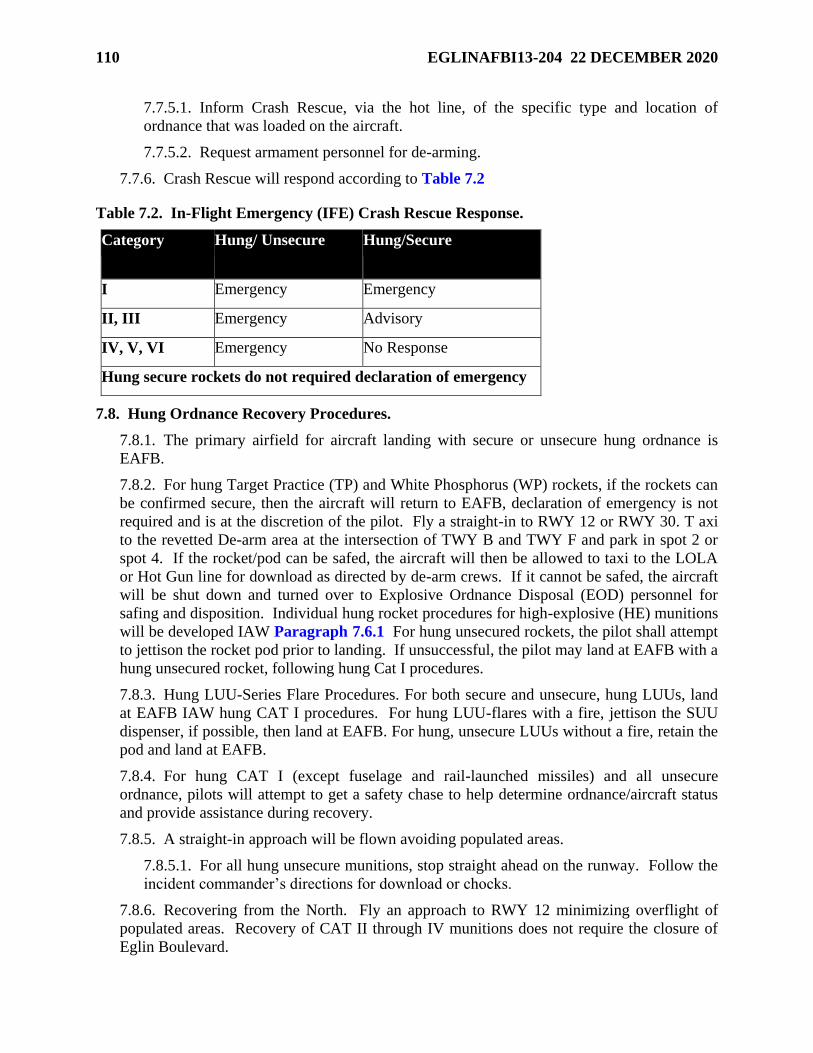
110 EGLINAFBI13-204 22 DECEMBER 2020
7.7.5.1. Inform Crash Rescue, via the hot line, of the specific type and location of
ordnance that was loaded on the aircraft.
7.7.5.2. Request armament personnel for de-arming.
7.7.6. Crash Rescue will respond according to Table 7.2
Table 7.2. In-Flight Emergency (IFE) Crash Rescue Response.
Category Hung/ Unsecure Hung/Secure
I Emergency Emergency
II, III Emergency Advisory
IV, V, VI Emergency No Response
Hung secure rockets do not required declaration of emergency
7.8. Hung Ordnance Recovery Procedures.
7.8.1. The primary airfield for aircraft landing with secure or unsecure hung ordnance is
EAFB.
7.8.2. For hung Target Practice (TP) and White Phosphorus (WP) rockets, if the rockets can
be confirmed secure, then the aircraft will return to EAFB, declaration of emergency is not
required and is at the discretion of the pilot. Fly a straight-in to RWY 12 or RWY 30. T axi
to the revetted De-arm area at the intersection of TWY B and TWY F and park in spot 2 or
spot 4. If the rocket/pod can be safed, the aircraft will then be allowed to taxi to the LOLA
or Hot Gun line for download as directed by de-arm crews. If it cannot be safed, the aircraft
will be shut down and turned over to Explosive Ordnance Disposal (EOD) personnel for
safing and disposition. Individual hung rocket procedures for high-explosive (HE) munitions
will be developed IAW Paragraph 7.6.1 For hung unsecured rockets, the pilot shall attempt
to jettison the rocket pod prior to landing. If unsuccessful, the pilot may land at EAFB with a
hung unsecured rocket, following hung Cat I procedures.
7.8.3. Hung LUU-Series Flare Procedures. For both secure and unsecure, hung LUUs, land
at EAFB IAW hung CAT I procedures. For hung LUU-flares with a fire, jettison the SUU
dispenser, if possible, then land at EAFB. For hung, unsecure LUUs without a fire, retain the
pod and land at EAFB.
7.8.4. For hung CAT I (except fuselage and rail-launched missiles) and all unsecure
ordnance, pilots will attempt to get a safety chase to help determine ordnance/aircraft status
and provide assistance during recovery.
7.8.5. A straight-in approach will be flown avoiding populated areas.
7.8.5.1. For all hung unsecure munitions, stop straight ahead on the runway. Follow the
incident commander’s directions for download or chocks.
7.8.6. Recovering from the North. Fly an approach to RWY 12 minimizing overflight of
populated areas. Recovery of CAT II through IV munitions does not require the closure of
Eglin Boulevard.
EGLINAFBI13-204 22 DECEMBER 2020 111
7.8.6.1. RWY 12 CAT I/II munitions. Attempt to exit the runway at TWY F-South.
Proceed to the revetted De-arm area at the intersection of TWY B and TWY F and park
in spot 2 or spot 4. If unable to land on RWY 12 due to winds or other conditions,
minimize overflight of populated areas and land on RWY 30 and follow the procedures in
Paragraph 7.8.7
7.8.6.2. RWY 12 with CAT I munitions. Eglin Boulevard, between the control tower
and Memorial Trail, must be closed. TWY H between TWY F and RWY 1/19 will also
be closed. Memorial Trail must also be closed to traffic crossing the departure end
between Eglin Boulevard and the horse stables.
7.8.7. RWY 30 CAT I/II munitions. Attempt to exit the runway at TWY E. Proceed to the
revetted De-arm pad area at the intersection of TWY B and TWY F and park in spot 2 or spot
4. If unable to land on RWY 30 due to winds or other conditions, minimize overflight of
populated areas and land on RWY 12 and follow the procedures in Paragraph 7.8.6
7.8.7.1. An initial 300’ safety zone will be established. The safety zone may be adjusted
by the incident commander as required. The incident command may consider closing
taxiways, runways and traffic roads to ensure safety.
7.8.8. For aircraft recovering with hung secure CAT III/IV munitions, taxi to normal de-arm
areas at TWY G or TWY D. Recovery of aircraft with CAT II through IV munitions does
not require closure of any roads.
7.8.9. Weapons personnel will inspect aircraft with hung ordnance and determine if the
aircraft can proceed to the parking area, or if it must be shut down. Aircrew taxiing back to
Hot Gun 1 will request to taxi on RWY 1, exiting at TWY P. If the aircraft must be shut
down, Weapons personnel will safe the hung ordnance and have the arm/de-arm crew pin all
remaining munitions. EOD personnel will take other necessary emergency actions as
required.
7.8.9.1. De-arm crew (composed of weapons personnel) will notify the pilot of action
taken to safe hung ordnance. A headset for aircraft interphone is required.
7.8.10. In the event RWY 1 is used for landing, Hot Gun 1 will be used in place of the
revetted De- arm area at the intersection of TWY B and TWY F when previously required
(i.e., CAT I/II hung ordnance). Attempt to exit RWY 1 at TWY P and park facing the berm.
7.8.11. For unique munitions requiring special handling (i.e., thermal batteries), follow
ground procedures approved during the 96 TW TAB, 53 WG Test Plan, or by the 33 OG/CC.
All procedures must be approved by the 96 OG/CC.
7.8.12. Duke Field: The preferred recovery for a hung ordnance/jammed/unsafe gun
recovery to Duke Field is an approach to RWY 18.
7.8.12.1. Aircraft landing RWY 36 will perform a 180° right turn after landing, back-taxi
down the runway, and turn left onto TWY E-East. After crossing the LZ, continue onto
VL South Pad. If applicable, point forward firing ordnance east.
7.8.12.2. Aircraft landing RWY 18 will roll out to the end of runway, turn left onto TWY
E- East. After crossing the LZ, continue onto VL South Pad. If applicable, point hung
weapon east.
112 EGLINAFBI13-204 22 DECEMBER 2020
7.8.12.3. In event of simultaneous hung ordnance/jammed/unsafe gun recoveries, the
first aircraft landing will follow the procedures described in Paragraphs 7.8.11;
Paragraphs 7.8.12 If landing RWY 18, the second aircraft will remain on the runway
and stop south of the south BAK-12. If landing RWY 36, the second aircraft will execute
a 180-degree turn at the end of the runway and proceed south, and stop south of the south
BAK-12.
7.8.12.4. The VL South Pad, Duke Field DZ, and the LZ will be temporarily closed or
suspended until the Airfield Manager or designated representative reopens them.
7.8.12.5. The Fire Department will have Weapons Maintenance attempt to immediately
safe the weapon. If the weapon is breached or unsecure, EOD teams will determine the
weapon status. After munitions are safed, the aircraft may depart for original destination
or be relocated for parking.
7.9. IFR Hung Ordnance Recovery Routes.
7.9.1. EAFB. Expect radar vectors to avoid populated areas to the maximum extent
possible. Expect clearance for standard recoveries: RWY 1/30, Eglin North Recovery, and
RWY 12/19, DDUNE Recovery. If weather is IFR, expect applicable instrument approach.
The pilot will request to land on the runway most appropriate for the situation, i.e., ordnance
carried, weather.
7.9.2. Duke Field: Expect radar vectors to avoid populated areas to the maximum extent
possible. In IFR conditions, expect to land via ILS to RWY 18 to avoid overflight of EAFB
and populated areas.
7.9.3. Hurlburt Field: Approaches shall be under radar control except during lost
communications conditions. Make every effort to avoid populated areas as soon as visual
contact with the runway environment is made.
7.10. De-Arming Procedures.
7.10.1. All aircraft will proceed through de-arm immediately after landing, regardless of
munitions carried in order to have safety pins/devices installed prior to taxiing back to
parking. Aircrew will verify all armament switches are OFF/SAFE and hold hands in view
of armament personnel during de-arming operations.
7.10.2. Aircraft with forward firing ordnance should taxi so as to eliminate or minimize the
time the aircraft is pointed toward an inhabited area. Minimize pointing forward firing
ordnance toward inhabited areas by continuing to the end of the runway before turning
toward the de-arm area.
7.10.3. Host and associate organizations will ensure the appropriate arm/de-arm areas are
manned by arm/de-arm crews during launch and recovery of unit aircraft regardless of
munitions carried.
7.10.4. Arm/de-arm crews will check all unexpended ordnance as soon as the aircraft is
parked at the arm/de-arm area and make sure munitions are still loaded/installed properly.
EGLINAFBI13-204 22 DECEMBER 2020 113
7.10.5. When any aircraft not requiring use of the de-arm area (e.g., C-130) exits the
runway, aircrew should verify status of weapons system. If any hung munitions condition
exists, aircraft will follow Tower instructions for a safe parking area to avoid conflict with
other aircraft movement on the ground until the system can be made safe to continue taxi to
park or the aircraft will be shutdown in position.
7.10.6. After receiving permission from the Tower to enter the runway, AMOPS and/or
EOD personnel shall make a runway inspection following the landing of an aircraft carrying
loaded CBU type munitions dispensers (downward or rearward dispensing) with
submunitions aboard. When this need exists, as identified during a TAB, EOD will advise
the tower of this requirement.
7.11. Radio Failure Procedures with Ordnance.
7.11.1. If one member of a flight has radio failure, that member will make a dry pass in
normal sequence by the tower, rock the wings to indicate a radio failure, pull off in the
direction of traffic, and establish an orbit 2,000 ft above the highest pattern remaining to be
flown, and await join up. If single ship, the pilot will accomplish the same procedure with
the exception of departing the test area after pulling off in the direction of traffic. The pilot
will squawk Code 7600. The Test Area Controller/RCO will notify EMC who will notify
Eglin Approach Control who will notify Eglin Tower.
7.11.2. If a pilot has radio failure with an emergency or with hung ordnance, the pilot will
make a dry pass (circumstances permitting), rock the wings, and break opposite the pattern
direction. Squawk Code 7700. The Test Area Controller/RCO will notify EMC who will
notify Eglin Approach Control who will notify Eglin Tower.
7.11.3. If the Test Area Controller/RCO loses radios, the aircraft will remain at pattern
altitude and attempt contact on alternate frequencies. Notify the JTTOCC if no contact. No
ordnance will be dropped without radio contact with the appropriate test area control/RCO
authority. The JTTOCC will monitor Test Area Control Common (Wolf Call) frequency
276.0 to approve test area operation/ordnance delivery on unmanned test areas, and to act as
a backup point of contact for manned test areas.
7.11.4. Other unit/command procedures for radio failure will be followed if they are more
restrictive.
7.12. Helicopter and AC-130 Gunship Weapon System Malfunctions.
7.12.1. The aircraft commander will be notified of any weapon system malfunction.
7.12.2. The aircraft will remain over assigned test area until the weapons can be placed in a
safe condition.
7.12.3. If system cannot be safed, or a hung flare condition exists, an emergency should be
declared. On recovery, minimize overflight of populated areas. Gun systems should not be
directed at populated areas. AC-130s use guidance IAW HFI 11-201 for specific jettison
procedures in the Eglin ranges.
7.13. Crash Procedures. If a known or suspected crash occurs on or near the test area, the
following actions will be taken by the RCO:
7.13.1. Close the test area.
114 EGLINAFBI13-204 22 DECEMBER 2020
7.13.2. Request a specific flight member to notify Eglin Tower.
7.13.3. Call Eglin AMOPS at COMM: (850) 882-5313/DSN: 872-5313 and provide all
known information, including crash site location, caller's name, and phone number.
7.13.4. Notify the Eglin Command Post at COMM: (850) 883-4020/DSN: 875-4020 with
the same information.
7.13.5. Remain in the control tower to coordinate rescue action and provide information.
7.14. RCO Procedures during Emergencies.
7.14.1. In-Flight Emergency/Hung Ordnance. The RCO will notify the EMC as soon as
possible when an aircraft has a problem necessitating special recovery procedures.
7.14.2. Communication Failure. In the event of radio failure, the RCO will:
7.14.2.1. Attempt contact on the field radio, secondary test area frequency, or EMC
frequency.
7.14.2.2. If it is necessary to abort a pass by a delivery aircraft, fire one flare from the
control tower.
7.14.2.3. If it is necessary to close the test area, fire two flares from the control tower.
7.14.2.4. Notify EMC by landline of test area radio problems or failure.
7.14.3. Notify EMC immediately when an aircraft departs the test area with apparent radio
failure or an emergency.
EGLINAFBI13-204 22 DECEMBER 2020 115
Chapter 8
TEST MISSION PROCEDURES
8.1. Test Area Scheduling.
8.1.1. Test area airspace will be scheduled according to EAFBI 13-204, Mission Scheduling
and Control. This instruction also contains procedures for scheduling “shared airspace,”
which enables a lower priority mission to be scheduled with a higher priority mission by
deconfliction of mission profiles, enabling maximum use of test area airspace.
8.2. Test Area Control. All test area operations must have clearance and two-way radio
communication with the appropriate test area RCO before and during ordnance release or
launching operations. Callsigns for appropriate test area control authorities are listed in Table
8.1
8.2.1. Warning Area/Water Missions. The aircrew is responsible for ensuring that they meet
all safety criteria and procedures to include those stipulated in the Safety Appendix issued for
the particular test/mission being conducted before going hot over water within all scheduled
warning airspace. The aircraft commander is designated as the safety observer for all hot
missions while in scheduled warning airspace. For those missions using the CCF (Call sign
CHAMBER), as mission control, approval from Chamber is required before going hot.
8.2.2. For manned test areas, the Test Area Controller is the appropriate authority for
approval of test area operations and the RCO is the appropriate authority for expenditure of
ordnance on the test area.
8.2.2.1. Test Area Controllers performing RCO duties must meet the criteria and
qualifications IAW AFI 13-212.
8.2.3. For unmanned test areas, the JTTOCC (Call sign WOLF CALL) is the appropriate test
area control authority. The JTTOCC monitors frequency 276.0 to approve test area
operation/ordnance delivery on unmanned test areas, and as a backup point of contact for
manned test areas. NOTE: Aircrew will check in, obtain clearance, and check out with the
JTTOCC, but will monitor their assigned mission frequency when working the unmanned
test area.
8.2.4. The RCO is responsible for the conduct and safety of ordnance delivery missions after
obtaining assurance from the Test Area Controller that the gates are closed and the test area
is clear of all personnel.
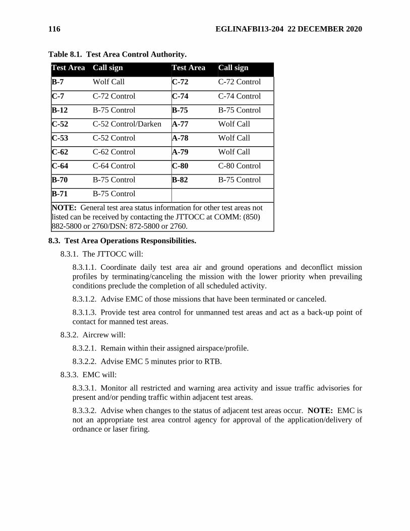
116 EGLINAFBI13-204 22 DECEMBER 2020
Table 8.1. Test Area Control Authority.
Test Area Call sign Test Area Call sign
B-7 Wolf Call C-72 C-72 Control
C-7 C-72 Control C-74 C-74 Control
B-12 B-75 Control B-75 B-75 Control
C-52 C-52 Control/Darken A-77 Wolf Call
C-53 C-52 Control A-78 Wolf Call
C-62 C-62 Control A-79 Wolf Call
C-64 C-64 Control C-80 C-80 Control
B-70 B-75 Control B-82 B-75 Control
B-71 B-75 Control
NOTE: General test area status information for other test areas not
listed can be received by contacting the JTTOCC at COMM: (850)
882-5800 or 2760/DSN: 872-5800 or 2760.
8.3. Test Area Operations Responsibilities.
8.3.1. The JTTOCC will:
8.3.1.1. Coordinate daily test area air and ground operations and deconflict mission
profiles by terminating/canceling the mission with the lower priority when prevailing
conditions preclude the completion of all scheduled activity.
8.3.1.2. Advise EMC of those missions that have been terminated or canceled.
8.3.1.3. Provide test area control for unmanned test areas and act as a back-up point of
contact for manned test areas.
8.3.2. Aircrew will:
8.3.2.1. Remain within their assigned airspace/profile.
8.3.2.2. Advise EMC 5 minutes prior to RTB.
8.3.3. EMC will:
8.3.3.1. Monitor all restricted and warning area activity and issue traffic advisories for
present and/or pending traffic within adjacent test areas.
8.3.3.2. Advise when changes to the status of adjacent test areas occur. NOTE: EMC is
not an appropriate test area control agency for approval of the application/delivery of
ordnance or laser firing.
EGLINAFBI13-204 22 DECEMBER 2020 117
8.3.3.3. Place aircraft in a "safety hold" (immediate discontinuance of mission,
aircraft/ground crew activities and follow ATC instructions until mission can be resumed
or is canceled) when the aircraft is unable to remain within its approved profile, the safety
of other aircraft is in jeopardy, until the problem is resolved, or the aircraft returns to
base.
8.3.3.4. Advise the JTTOCC when aircraft are placed in or removed from a "safety
hold," or when prevailing conditions, such as overlapping profiles, etc., preclude the
completion of mission activity.
8.3.3.5. Route profile deviations reported by Eglin Mission through the ERCF Chief
Controller to Chief, Airspace Management and Mission Planning (CAMMP). The
CAMMP will initiate the 96 TW Form 115, Profile Deviation Report, and submit it to the
Airspace Manager. Reports shall be completed within 30 days of initial notification of
the deviation and submitted to 96 OGV for final disposition. Copies of the completed 96
TW Form 115 shall also be forwarded to 96 OSS/CC and 96 TW/SEF. Final reports shall
be retained by 96 OSS/OSA.
8.3.4. Test Engineers/Project Officers. Test engineers or project officers will brief aircrew
on conflicting or shared airspace missions.
8.4. Departure Procedures.
8.4.1. Arm/De-arm Areas. EAFB's arm/de-arm areas are depicted in Attachment 2. The de-
arm area for Duke Field is an 800 ft circle centered on TWY E.
8.4.2. Takeoff.
8.4.2.1. Takeoff directions should be selected, as far as safety permits, to allow the most
expeditious route to the desired test area; however, takeoffs with externally loaded
ordnance will normally not be made on RWY 1 for Cat I, II, and III ordnance. Under
extenuating circumstances, the 96 OG/CC may authorize RWY 1 departures for Cat I, II
or III ordnance. Prior approval is required.
8.5. Test Area Procedures for Ordnance Delivery Missions.
8.5.1. Clearance into a restricted/warning area must be obtained from EMC. Clearance from
EMC into a restricted/warning area and profile is not clearance to release. Clearance to
release on the test area must be obtained from the appropriate test area control authority
listed in Table 8.1 or IAW Paragraph 8.2
8.5.2. The flight lead shall check in with callsign, mission number, type ordnance (unless
prohibited for security reasons) and number of aircraft in the flight.
8.5.3. Armament switches will remain OFF/SAFE until the aircraft enters the specified
safety profile for the test area as defined in the Safety Appendix of the TD. At that time, the
munitions may be prepared for release (warm-up, station selection, etc.) up to, but not
including, final release arming. Final release arming selection will be made on base leg. For
level and climbing deliveries, final release arming will not be made until wings level on final
within the safety profile. Release arming will be returned to the OFF/SAFE position after
each delivery if the aircraft will depart the safety profile.
118 EGLINAFBI13-204 22 DECEMBER 2020
8.5.4. During test missions, aircraft carrying ordnance will call "HOT" or "DRY" on both the
base leg and final run-in position of each pass. The base call is required whether range
instrumentation is being used or not. Aircraft position at the time of this call will be
dependent on the mission profile shape and size, but will be no less than 30 seconds from the
point at which the ordnance leaves the aircraft. The test area control authority will
acknowledge each call and clear the pass "HOT" or "DRY." If no acknowledgment is
received, the pass will be completed "DRY" and reaffirmed "DRY" by the aircraft
commander. “HOT/DRY” base calls are not required for training missions.
8.5.5. Patterns and applicable test area procedures for a test mission will conform to the TD.
8.5.6. Prior to departing the test area on any ordnance delivery mission, each aircraft will be
visually checked for hung ordnance. If a visual check cannot be accomplished, the pilot will
assume hung ordnance and will follow the hung ordnance procedures. A visual check may
be made by:
8.5.6.1. The delivery aircraft, if the crew has the station in sight,
8.5.6.2. The delivery aircraft or RCO, if the number of impacts can be counted,
8.5.6.3. The RCO--aircraft will not descend below 200 ft AGL nor fly within 500 ft slant
range of the tower during the fly-by check (Cat I and II ordnance only) or,
8.5.6.4. A chase aircraft.
8.5.7. Pilots will safe all armament switches prior to departing the test area.
EGLINAFBI13-204 22 DECEMBER 2020 119
Chapter 9
RANGE OPERATIONS
9.1. Purpose. This chapter provides guidance for operations within the Eglin range complex
and the expenditure of ordnance from fighter/attack/Forward Air Control (FAC)/AC-130 aircraft,
and helicopters on test missions or weapons employment training missions. Modification of
these procedures, if necessary, and complete procedures for any other test area will be contained
in the Safety Appendix to the TD documenting the individual training programs. All coordinates
listed are based on the World Geodetic Survey, 1984 (WGS 84), rounded to the nearest 100th
and derived from AAC Technical Facilities Manual, Volume II, July 1996. For further
information on available facilities and operating procedures within the Eglin Range Complex,
refer to EAFBI 13-212, Range Planning and Operations.
9.2. Policies.
9.2.1. When operating outside the boundaries of the Eglin reservation, and not on an
approved low- level route, comply with the procedures outlined in Attachment 45 and
Paragraph 4.37
9.3. Test Area Safety. In the event an aircraft crashes on the test area, the flight or deputy
leader will assist the appropriate test area control authority in determining the exact crash
location for relay to rescue crews. The flight/deputy leader will assist the Test Area
Controller/RCO until released or fuel state requires departure.
9.4. General Test Area Procedures.
9.4.1. Aircraft will be cleared into and out of Eglin restricted airspace by EMC. Munitions
release will be IAW Chapter 8.
9.4.2. Patterns that require maneuvering outside restricted airspace will require prior
coordination with EMC, who will attempt to obtain the necessary airspace from the
appropriate agency.
9.4.3. A maximum of four aircraft may be scheduled in a test area at any one time, unless
exceptions allowed by other guidance and approved by the RCO.
9.4.4. Up to three dissimilar types aircraft of compatible airspeed will be allowed in the
weapons delivery pattern at any one time. Exceptions to these rules are authorized only with
the specific approval of the 96 OG/CC, 85 TEG/CC, 1 SOW/CC, or 919 SOW/CC for
aircraft under their operational control. A copy of that approval will be provided to 96
TW/SE.
9.5. Test Area Entry.
9.5.1. Flights proceeding directly to the test area after takeoff will be handed off to EMC as
soon as possible after departure. If the flight is scheduled to fly a low-level route prior to test
area entry, the flight leader should request a VFR clearance to the appropriate initial point
(North IP or East IP) and contact EMC prior to entry into the restricted area.
120 EGLINAFBI13-204 22 DECEMBER 2020
9.5.2. Restricted Area Clearance. The flight leader will contact EMC for clearance into the
restricted area. This call will include callsign, mission number, and number of aircraft in the
flight. Permission to enter the restricted area must be received prior to entry. NOTE:
Clearance into a restricted area from EMC is not permission to expend ordnance on the test
area.
9.6. Test Area C-62 Procedures.
9.6.1. Flight lead will give flight callsign, number and type of aircraft, number and type
ordnance, sequence of events, targets, release conditions, type of patterns to be flown, and
verify any laser operations. Ordnance will not be expended without clearance from the Test
Area Controller/RCO. Flight leaders will inform the Test Area Controller/RCO of any
changes to events.
9.6.2. Holding Points and Altitudes: If immediate clearance into the restricted area or the
test area is not possible, flights entering from other than low-level routes will hold at an
assigned altitude and holding point until cleared by the controlling agency (ATC or EMC).
Flights entering from the northern low-level route may hold at the north initial point (North
IP).
9.6.2.1. Entry from Low-Level Routes. Entry onto the test area directly from a low-level
route will be flown at the following altitudes:
9.6.2.2. North IP (30°58.5’N/86°21.0’W; 200 ft AGL)--Maintain a minimum of 1,500 ft
AGL until reaching the boundary of the Eglin Reservation (Interstate 10). NOTE:
Exercise extreme vigilance north of Test Area C-62 for helicopter and light aircraft
traffic.
9.6.3. Specific allowable test area procedures are defined by the program’s TD and
associated Safety Appendix. EAFBI 13-212 lists current training targets, release conditions
and, as appropriate, may be referenced in the Safety Appendix.
9.6.4. Simulated Nuclear Delivery and Radar Pattern Procedures.
9.6.4.1. Procedures will be according to Table 9.1
9.6.4.2. Switch positions: The master arm switch will not be turned ON until passing
Interstate 10 or Highway 331 inbound to Test Area C-62. When performing multiple
deliveries, the master arm switch will be turned OFF or SIM every time prior to departing
the reservation. NOTE: The nuclear tone transmit switch will remain OFF at all times.
Table 9.1. Test Area C-62 Delivery Headings and Pattern Directions.
EVENT HEADING PATTERN DIRECTION
Nuclear (North IP) 159° ±5° Right or Left
Nuclear (East IP) 282° ±5° Right or Left
Nuclear (American Farms IP) 300° Right Figure Eight
EGLINAFBI13-204 22 DECEMBER 2020 121
9.6.4.3. Radio calls:
9.6.4.3.1. Turning base: "(Call sign), BASE."
9.6.4.3.2. Highway 331 or Interstate 10: "(Call sign), HIGHWAY, (event)."
9.6.4.3.3. Off target: "(Call sign), OFF, (wet or dry).
9.6.5. Night Procedures.
9.6.5.1. Flight will normally be two-ship maximum (three-ship allowed in nuclear
pattern).
9.6.5.2. The position of SPADATS relative to C-62 will be briefed for all night attack
missions.
9.6.5.3. Four clusters of lights are located around the main bombing pylon (TT-1). The
lights are positioned on the cardinal headings around the edge of the cleared area, 200 ft
from the pylon.
9.6.5.4. Entry and orbit are the same as daytime.
9.6.5.5. Minimum altitude for holding at night is 4,000 ft MSL.
9.6.5.6. All night missions require an RCO.
9.7. Test Area C-52N Procedures.
9.7.1. Test Area C-52N is a manned, scored test area that can be used for weapons
employment training. Also, it can be used as an unmanned, unscored test area for random
attacks.
9.7.2. Entry/Holding.
9.7.2.1. Range Clearance. Normal entry will be from the Freeport Bridge orbit point;
however, EMC can provide entry from other locations. When the flight is cleared to the
assigned test area frequency, the flight leader will establish contact with the Test Area
Controller/RCO (callsign “C- 52 Control/Darken”). Flight lead will give flight callsign,
number and type of aircraft, number and type ordnance, sequence of events, target,
release conditions, type of patterns to be flown, verify bomb fuse type, and verify any
laser operations. The flight will be cleared on the test area or directed to hold. The flight
will be advised of any restrictions to delivery patterns and given the current altimeter
setting. Most recent wind information will also be provided. All flight members will
acknowledge this information. Ordnance will not be expended without clearance from
the Test Area Controller/RCO. Flight leaders will inform the Test Area Controller/RCO
of any changes to events.
9.7.2.1.1. AC-130 Clearance Procedures. Comply with HFI 11-201, Fixed and
Rotary Wing Operations, range clearing procedures for C-52.
9.7.2.1.2. Holding Points and Altitudes: If holding is required, the flight will hold
northeast of the Freeport Bridge at a minimum altitude of 2,000 ft MSL (day) and
4,000 ft MSL (night).
122 EGLINAFBI13-204 22 DECEMBER 2020
9.7.3. Test Area Procedures: Specific allowable test area procedures are defined by the
program’s Test Directive and associated Safety Appendix. EAFBI 13-212 lists current
training targets, release conditions and, as appropriate, may be referenced in the Safety
Appendix.
9.7.4. Night Procedures.
9.7.4.1. All night procedures require an RCO.
9.7.4.2. During the Freeport Bridge entry, the flight will attain proper spacing on the turn
to downwind or as briefed by the flight lead.
9.7.4.3. When a cargo-type flare ship is to be used on Test Area C-52N, flights will enter
the test area at or above 4,000 ft MSL.
9.7.4.4. A maximum of four aircraft will be in the night test area pattern at any time.
Four aircraft are authorized only if one is being used for flare delivery, otherwise no more
than three aircraft are authorized.
9.7.4.5. The flare launch aircraft will fly a circular or elliptical right-hand pattern.
9.7.4.6. When operating with a flare delivery aircraft, all ordnance delivery patterns will
be left hand. Attack heading is restricted to 090 degree ± 20 degree.
9.7.4.7. Flares will not be dropped when surface winds exceed 15 knots or when the fire
index, as determined by Natural Resources Branch (96 CEG/CEVSN), presents an
unacceptable hazard.
9.7.4.8. When flares are employed and the restrictions previously outlined in this chapter
are complied with, aircraft are authorized to expend ordnance against any target within C-
52N. When flare illumination is not used, deliveries are limited to targets illuminated by
ground lights. At least two ground lights will be illuminated for weapons delivery using
ground illumination only.
9.7.4.9. Descent from base leg altitude will not be made until after the turn to final is
initiated, visual orientation with the target area is accomplished, and the flare ship is in
sight.
9.7.4.10. It is the responsibility of the ordnance delivery aircrew to maintain safe
separation from the flare ship.
9.7.4.11. Flare aircraft procedures (SUU-25):
9.7.4.11.1. If a flare should ignite while still in the dispenser, the SUU-25 will be
jettisoned.
9.7.4.11.2. Aircraft carrying SUU-25 flare dispensers will select only one station at a
time, and will dispense all flares from one station prior to dispensing flares from the
other station.
9.7.4.11.3. Alternate release of flares and weapons by the same aircraft is prohibited.
9.7.4.11.4. Minimum altitude for flare deliveries is 3,000 ft AGL. NOTE: All LUU-
2 deliveries will be planned to ensure flare is burned out by 500 ft AGL.
EGLINAFBI13-204 22 DECEMBER 2020 123
9.8. Test Area B-6 (Eglin Field 6, Army Ranger Camp, Camp Rudder). No aircraft will
overfly Eglin Field 6 below 1,500 ft AGL (1,700 ft MSL) unless intending to land there or with
specific approval of 96 OG/CC. This no-overflight area has a 1 NM radius centered on the Field
6 Runway intersection. In cases where overflight approval is granted, the responsible project
officer will provide Camp Rudder operations personnel with information on date, time, altitude,
speed, type of aircraft, and reason for the operation 48 hours in advance of the scheduled
overflight.
9.9. Rejoins/Departures.
9.9.1. The Test Area Controller/RCO will broadcast a "5 MINUTES UNTIL END OF TEST
AREA PERIOD " information call. Flight leaders will make sure their flights are clear of the
test area at the conclusion of their test area period, or coordinate an extension through EMC.
9.9.2. After join-up and prior to departing the test area, the flight leader will advise the RCO
and Test Area Controller of any hung/unexpended ordnance by type and aircraft.
Hung/unexpended ordnance procedures are in Chapter 7.
9.9.3. The flight leader will pass recovery requirements to EMC prior to departing the test
area.
9.9.4. Emergency Departures. In an emergency, a pilot may clear the test area from any
position and proceed as necessary to the field of intended landing. Extreme caution should
be used in departing R-2914. As soon as possible notify EMC with intentions.
9.10. RCO Procedures. If an RCO is used to control a test area, the RCO will:
9.10.1. Prior to departing for the test area:
9.10.1.1. Determine test area status and accessibility.
9.10.1.2. Check on any deviations to scheduled test area missions.
9.10.1.3. Receive any additional instructions from the duty controller or SOF.
9.10.1.4. Be familiar with the Safety Appendix to the TD.
9.10.2. Be in position on the designated test area before the flight is cleared onto the test
area.
9.10.3. Determine the operational status of the test area items listed in Table 9.2 according
to AFI 13-212.
Table 9.2. AFI 13-212 Items.
Skip Panels Strafe Targets Strafe Impact Area
Flares and Flare Gun Control Tower Bomb Targets
Acoustical Scorer Wind Device Facilities
Secondary Radios Primary Radios Personnel
124 EGLINAFBI13-204 22 DECEMBER 2020
9.10.4. Ensure test area facilities, personnel, and weather are suitable for test area operations.
9.10.5. Brief test area personnel on the scheduled missions and control procedures.
9.10.6. Confirm with the Test Area Controller that all range gates are closed and the test area
has been visually cleared of all personnel prior to flight clearance on the test area.
9.10.7. Obtain current altimeter setting and information on any activity that may restrict test
area operations from EMC.
9.10.8. Obtain flight lineup, crew numbers, events, and targets to be used from all flights
prior to entering the test area.
9.10.9. Provide flight with clearance into the test area, the current altimeter setting, winds
and weather observations, profile/pattern restrictions (if any), and assigned targets (when
applicable).
9.10.10. Assume procedural control of all flights entering the test area and make sure aircraft
are operated according to sound safety practices and appropriate directives.
9.10.11. Observe all aircraft in the pattern insofar as possible, noting specifically pattern and
delivery techniques and spacing.
9.10.12. Issue clearance for each delivery upon determining that aircraft position and
spacing will allow release of the appropriate ordnance and subsequent safe recovery of the
aircraft.
9.10.13. Observe each aircraft flight path during the final phase of delivery.
9.10.14. Notify the aircrew when they are unsafe or have committed a foul (as established in
AFI 11-214, Air Operations Rules and Procedures).
9.10.15. Assess fouls and take corrective action according to command directives.
9.10.16. Require all flight members to acknowledge directive radio transmissions.
9.10.17. Monitor bird activity in the target area, especially during hours around dawn and
dusk, and advise aircrew members.
9.10.18. When flights are attempting to meet a firm time over target (TOT), verify weapons
impact with a "SPLASH" call.
9.10.19. Monitor bomb plotting and event/score documentation in the control tower.
9.10.20. Ensure an orderly flow of missions on and off the test area by advising flights when
they are approaching the final 5 minutes of their test area period.
9.10.21. As soon as departing flights have joined up, obtain from them a summary of
hung/unexpended ordnance by type and aircraft.
9.10.22. For those flights exercising forward air controller (FAC) profiles on a manned test
area, surrender tactical control to the FAC during the employment phases of the mission. All
FAC controlling aircraft on any Eglin range/test area must be certified by the Chief RCO for
each range upon which the individual will perform FAC duties (e.g., Range 52 Chief RCO to
work Range 52, Range 62 Chief RCO to work Range 62). Monitor the conduct of the flight
for compliance with stipulated safety criteria.
EGLINAFBI13-204 22 DECEMBER 2020 125
9.10.23. For those flights exercising random attack profiles, surrender RCO responsibilities
to the FAC or flight lead. Make sure the test area is clear and all personnel have evacuated
the complex before the flight enters the test area.
9.10.24. In addition to those duties outlined above, the night RCO will:
9.10.24.1. Make sure Jackson Guard has been consulted to determine if the burning
index will allow flare delivery and surface winds do not exceed 15 knots.
9.10.24.2. If requested, establish flare drop sequence, altitude, delay, and burnout
altitude with the flare ship.
9.10.24.3. Monitor burned out or dud flares and immediately notify flight members of
potential hazards. Hold fighters high and dry if burned out or dud flares present a hazard,
resuming operation only when the hazard has passed.
9.10.24.4. Make sure all delivery aircrew call "FLARE SHIP IN SIGHT" when turning
final if a cargo ship is used for flaring or when a fighter flare ship delivery pattern
opposes the fighter pattern.
9.10.24.5. Monitor aircraft spacing throughout the pattern with special emphasis on the
final approach, recovery, and turn to downwind leg.
9.10.25. Crash Procedures. See Paragraph 7.13
9.10.26. Emergency Procedures: In accordance with Chapter 7.
9.10.27. Weather:
9.10.27.1. Delivery patterns will not be allowed when the weather is below the specified
minimum for that event. When a weather observer is not present on the test area, a pilot
report (PIREP) can be used as an aid in determining test area weather.
9.10.27.2. The RCO can request additional test area weather observations when
conditions so dictate. Additional weather requirements should be coordinated with 96
WS as early as possible.
9.10.28. Strafe Target Scoring:
9.10.28.1. Low-angle strafe scoring will normally be accomplished on the acoustically
scored targets. Acoustical scores will be recorded and the number of hits transmitted to
the delivery aircraft after each pass.
9.10.28.2. When strafe target manual scoring or maintenance is accomplished while
aircraft are in the delivery pattern, the RCO will direct the flight to avoid overflight of the
strafe target area by 1,500 ft MSL, permit no strafing, and allow weapons deliveries only
on the nuclear target. The target team chief will illuminate the red warning lights inside
the control tower and contact the RCO prior to departing for the strafe target area. Upon
return, the team chief will again notify the RCO confirming that all personnel are off the
test area.
126 EGLINAFBI13-204 22 DECEMBER 2020
9.10.28.3. Test area personnel will not normally hoist the strafe panels when surface
winds exceed 20 knots.
9.10.29. Weapons Delivery Scoring Record. The RCO is responsible for proper completion
of the weapons delivery scoring record. Although test area personnel actually complete the
scoring record while the mission is in progress, it is essential that the RCO verify its accuracy
by comparing it with the delivery data that was recorded in the control tower.
EGLINAFBI13-204 22 DECEMBER 2020 127
Chapter 10
OPERATIONAL PROCEDURES FOR THE EMPLOYMENT OF ELECTRONIC
PROTECTIVE MEASURES (EPM), CHAFF, FLARES, AND LASERS
10.1. Purpose. This chapter provides guidance for procedures for the employment of EPM,
chaff, flares, and lasers within the Eglin range complex. Frequency requirements will be
coordinated with the DoD Gulf Area Frequency Coordinator [DoD GAFC (96 CS/SCXF)]. 96
OSS Frequency Control and Analysis (96 OSS/OSOQ) is the initial point of contact for
notification of all Radio Frequency Interference (RFI), and will exercise authority to terminate
radiation of the detected source of interference. The DoD GAFC will be the final authority for
resolution of frequency conflicts/interference.
10.2. Responsibilities.
10.2.1. Flight leaders, individual pilots, or Electronic Warfare Officers (EWO) will include
applicable portions of this instruction during flight briefings.
10.2.2. Commanders of associate and transient organizations using self-protection systems
are responsible for compliance with this chapter.
10.2.3. The host unit is responsible for providing instructions and procedures to units
visiting the Eglin complex for missions involving EPM, chaff, or flare, regardless of whether
or not the unit launches or recovers at EAFB.
10.2.4. Units desiring to deploy chaff and EPM must submit mission requests in advance to
96 OSS/OSOQ to coordinate the activity with FAA Jacksonville Center. If normal submittal
times are not met, then blackboards will have to be submitted by 1300L one day prior to
mission date. 96 OSS/OSO will be responsible for notifying the organization scheduling
representative when missions are denied the use of chaff, flares, or EPM.
10.2.5. Frequency Control and Analysis (FCA) (96 OSS/OSOQ) is responsible for the
scheduling of EPM and chaff within Eglin Restricted Areas and W-151/W-470. The area of
responsibility is bounded on the north by 31º00’N, on the east by 83º30’W, on the south by
28º 15’N, and on the west by 86º48’W.
10.2.6. Operations officers will ensure all aircrew conducting EPM, carrying chaff, or flares
on Eglin Complex fields or test areas understand the provisions of this instruction before
operations are attempted. Additionally, they will establish procedures to ensure aircrew
know the areas and times during which they are scheduled to employ EPM, chaff, or flares.
EPM, chaff, and flares will not be employed in the Eglin test area complex unless scheduled
in compliance with this instruction (as appropriate) and authorized by an appropriate TD and
applicable Radio Frequency Authorization (RFA).
10.2.7. All aircraft conducting EPM or employing chaff are required to monitor 243.0 MHz
(UHF Guard channel) and stop employment operations upon hearing a “STOP (or CEASE)
BUZZER/STREAMBURST” call from the appropriate controlling agency [e.g., EMC,
Military Radar Unit (MRU), or CCF (callsign CHAMBER)].
128 EGLINAFBI13-204 22 DECEMBER 2020
10.2.7.1. After “STOP (or CEASE) BUZZER/STREAMBURST” has been given and the
aircraft has ceased EPM, then FCA will try to determine when and what part of the EPM
can be resumed. If the EPM band causing the problem cannot be separated or the
frequency bands cannot be determined, then the EPM is to remain off until the safety
issue or emergency has been cleared and FCA has given the approval to resume.
10.2.8. Each unit will provide 96 OSS/OSOQ the name and phone numbers of its operations
officer to contact for interference resolution.
10.3. Authorized Systems. All systems operating with a valid RFA from 96 CS/SCXF and
properly scheduled through 96 RANSS/DOSF are authorized on the range.
10.4. Scheduling.
10.4.1. EPM, chaff, and flares should be requested as deletable items, if appropriate, to
preclude missions being nonscheduled for conflicts in this area.
10.4.2. Missions desiring to use EPM will require inclusion of the appropriate RFA line
numbers on the mission request form. EPM will be scheduled on a mission-to-mission basis,
regardless of the working area.
10.4.3. Individual aircrew or units will contact their organization’s scheduling agency if
changes to the schedule are desired. These changes must be coordinated through 96 RANSS
scheduling prior to 1300L on the day preceding the mission.
10.5. Departure Procedures. Arming and de-arming of chaff and flare systems will be
conducted in the normal arm/de-arm areas. Start, taxi, arming, and takeoff will be according to
the procedures in Chapter 8.
10.6. Flare Employment Procedures. All missions employing flares will be scheduled as hot
missions. Any airspace changes must be coordinated through the JTTOCC, and informed that
the mission intends to drop flares. JTTOCC shall notify the Coast Guard of changes in flare
activity.
10.6.1. W-151/W-470: Flares may be employed within W-151 and W-470 provided the
aircraft is above 1,500 ft AGL or the aircraft is below 1,500 ft AGL and at least 3 NM from
any surface vessel, platform, or land mass. Flare operations within warning areas will be
under flight lead control.
10.6.2. Overland: Flares may be employed over the Eglin Reservation only. Avoid
expending flares over populated areas, personnel, or structures. Minimum release altitude
over authorized test areas is 200 ft AGL, and 500 ft AGL when not over authorized test
areas. Further restrictions may be imposed by 96 TW Test and Range Safety and central
scheduling authority (96 OSS/OSO) when required.
10.7. Chaff Employment Procedures: All missions employing chaff shall be scheduled.
Wind conditions and complexity of air traffic may make it necessary for EMC to terminate chaff
dispersal. Chaff dispersal outside the parameters identified in this chapter must be coordinated
according to FAA Handbook 7610.4, Special Military Operations, and approved by the GAFC.
10.7.1. W-151/W-470: Chaff will normally (depending upon test/training mission
requirements) be authorized within W-151/W-470, provided it is included under an
applicable RFA and meets the criteria for use outlined in the RFA.
EGLINAFBI13-204 22 DECEMBER 2020 129
10.7.1.1. Flight leads will ensure that operational chaff is not employed under any
conditions that would cause it to drift outside of the scheduled working area. Areas of
particular emphasis include to the south where it could interfere with the Gulf Crossing
Air Routes, drift into the North-South or East-West Corridors, or affect air traffic
facilities.
10.7.1.2. Chaff employment operations within the warning areas will be under flight lead
control.
10.7.2. Overland: Chaff drops in R-2915A, north of Auxiliary Field 6 and west of A-77, are
limited to 2,000 ft AGL and below. All other areas in R-2915A are limited to 4,000 ft AGL
and below. Chaff over C-52 in R-2914A is limited to 4,000 ft AGL and below. No chaff is
permitted in the North-South or East-West VFR Corridors. In all other areas of Eglin
restricted airspace, chaff is limited to 2,000 ft AGL and below. Strictly adhere to chaff type
requirements defined in the RFA (i.e., cannot use wide-band chaff when RFA permits use of
only narrow-band chaff).
10.7.2.1. Wind conditions and traffic complexity may make it necessary for ATC to
terminate chaff expenditure authorization. The final authority rests with EMC.
10.8. EPM Employment Procedures: All missions employing EPM shall be scheduled.
Normally, operations for F-15 Internal Countermeasures Set (ICS) I-band and below will be
approved, without exception, within W-151C, D, E, and F, provided operating under an
approved RFA. Flight leads, individual pilots, and EWOs are responsible for ensuring that EPM
is not conducted outside of the areas and times scheduled. Frequency interference problems will
be reported real-time to the JTTOCC. 96 OSS/OSOQ FCA will coordinate with the appropriate
organization operations officer(s) for immediate resolution.
10.9. Recoveries.
10.9.1. Pilots will ensure all EPM, chaff, and flare switches are OFF/SAFE prior to
departing the test and training area.
10.9.2. Aircraft returning to EAFB with unexpended chaff or flares may recover to the
overhead pattern.
10.9.3. De-arming will be according to Chapter 8.
10.9.4. Following de-arming, aircraft may return to parking on the Test Ramp according to
EAFBMAN 91-202.
10.9.5. Any malfunction of chaff or flare systems will be handled IAW Chapter 7
procedures.
10.10. Airborne Laser Operations.
10.10.1. In order to minimize the safety risk and maximize the opportunity for effective
testing/training, the procedures outlined in the following paragraphs will be used when
employing a targeting pod (e.g., LANTIRN/LITENING/SNIPER), or any other airborne laser
designation system.
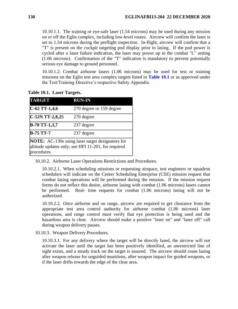
130 EGLINAFBI13-204 22 DECEMBER 2020
10.10.1.1. The training or eye-safe laser (1.54 microns) may be used during any mission
on or off the Eglin complex, including low-level routes. Aircrew will confirm the laser is
set to 1.54 microns during the preflight inspection. In-flight, aircrew will confirm that a
"T" is present on the cockpit targeting pod display prior to lasing. If the pod power is
cycled after a laser failure indication, the laser may power up in the combat "L" setting
(1.06 microns). Confirmation of the "T" indication is mandatory to prevent potentially
serious eye damage to ground personnel.
10.10.1.2. Combat airborne lasers (1.06 microns) may be used for test or training
missions on the Eglin test area complex targets listed in Table 10.1 or as approved under
the Test/Training Directive’s respective Safety Appendix.
Table 10.1. Laser Targets.
TARGET RUN-IN
C-62 TT-1,4,6 270 degree or 159 degree
C-52N TT-2,8,25 270 degree
B-70 TT-1,3,7 237 degree
B-75 TT-7 237 degree
NOTE: AC-130s using laser target designators for
altitude updates only; see HFI 11-201, for required
procedures.
10.10.2. Airborne Laser Operations Restrictions and Procedures.
10.10.2.1. When scheduling missions or requesting airspace, test engineers or squadron
schedulers will indicate on the Center Scheduling Enterprise (CSE) mission request that
combat lasing operations will be performed during the mission. If the mission request
forms do not reflect this desire, airborne lasing with combat (1.06 microns) lasers cannot
be performed. Real- time requests for combat (1.06 microns) lasing will not be
authorized.
10.10.2.2. Once airborne and on range, aircrew are required to get clearance from the
appropriate test area control authority for airborne combat (1.06 microns) laser
operations, and range control must verify that eye protection is being used and the
hazardous area is clear. Aircrew should make a positive "laser on" and "laser off" call
during weapon delivery passes.
10.10.3. Weapon Delivery Procedures.
10.10.3.1. For any delivery where the target will be directly lased, the aircrew will not
activate the laser until the target has been positively identified, an unrestricted line of
sight exists, and a steady track on the target is assured. The aircrew should cease lasing
after weapon release for unguided munitions, after weapon impact for guided weapons, or
if the laser drifts towards the edge of the clear area.
EGLINAFBI13-204 22 DECEMBER 2020 131
10.10.3.2. For deliveries where the target is not directly lased [i.e., Continuously
Designated Impact Point (CDIP)/Continuously Computed Impact Point (CCIP)], the
aircrew will not activate the laser until rolled-out wings level on final, and the laser (or
pipper) is aimed within the clear area. A good rule of thumb is to activate the laser at 5
sec prior to release. Cease lasing after weapon release.
10.10.3.3. Safety will determine the limits for test programs and reference applicable
parent regulations to determine limits per MDS for training events.
132 EGLINAFBI13-204 22 DECEMBER 2020
Chapter 11
SUPERSONIC OPERATIONS
11.1. Supersonic Operations. Supersonic flight operations over the Eglin Land Range and the
Eglin Gulf Test and Training Range shall be conducted IAW AFI 13-201, Airspace
Management, and the Eglin Supersonic Waiver 75-1.
11.1.1. Supersonic training may be accomplished over water above 10,000 ft MSL and at
least 15 NM from the coast. Supersonic training profiles below 10,000 ft MSL will be flown
a minimum of 25 NM from the coast if on a southerly heading, and a minimum of 50 NM
from the coast if on a northerly heading.
11.1.2. Supersonic flight test profiles must be approved through the TAB process and adhere
to the following restrictions:
11.1.2.1. All overland profiles below FL300 shall be performed on Test Area B-70 and
shall be restricted to a maximum over-pressure of 3.5 pounds per square foot (PSF) at a
distance of 5 NM from the aircraft ground track. In no case will an over-pressure
exceeding 3.5 PSF be allowed outside of the Eglin Land Range from the surface to
FL300.
11.1.2.2. All overland supersonic profiles shall terminate in a level flight attitude so as
not to expand the over-pressure envelope towards the ground.
11.1.2.3. Vehicular traffic on state roads and all personnel within the reservation shall be
adequately protected from over-pressure exposure during scheduled runs.
11.1.2.4. No supersonic missions over land shall be flown unless the test engineer has
notified the Public Affairs Office (96 TW/PA) the day prior to the mission. The test
engineer should again notify 96 TW/PA 1 hour prior to aircraft takeoff to confirm the
mission status and update any changes. Aircrew shall confirm that this has been done
before going to the aircraft.
11.1.2.5. Test teams shall make every effort to minimize dry supersonic passes overland.
11.1.2.6. Supersonic flight test profiles may be accomplished over water above 10,000 ft
MSL at least 25 NM from the coast. Supersonic flight test profiles below 10,000 ft MSL
will be flown a minimum of 25 NM from the coast if on a southerly heading, and a
minimum of 50 NM from the coast if on a northerly heading.
11.1.2.7. For supersonic flight test runs below 10,000 ft MSL, a boat check will be
accomplished prior to commencing the test run to ensure there are no boats within 5 NM
of the ground track.
EGLINAFBI13-204 22 DECEMBER 2020 133
Chapter 12
REMOTELY PILOTED AIRCRAFT (RPA)
12.1. General. RPA use airspace and airfields to conduct both test and training missions.
Training missions include initial qualification training, mission qualification training and
proficiency training of small RPA operators and sensor operators. This chapter will provide
information on airfields, airspace, airspace request processes, safety requirements, emergency
procedures, and weapons employment.
12.2. Airfields for RPA. Depending on the type and size of RPA, a prepared runway/landing
zone may or may not be required. Small Unmanned Aircraft Systems (SUAS) and Micro Air
Vehicles (MAV) may be hand launched (e.g., WASP, Raven), pneumatically launched (e.g.,
Shadow, Scan Eagle), or takeoff from a runway (e.g., Hunter, Dakota, Pioneer). There currently
is no universally accepted definition of RPA, SUAS, or MAV between DoD and commercial
vendors. From a safety perspective, anything above 20 knots or 1 pound can be lethal. SUAS
may be recovered by net, skyhook, belly in with no landing gear, or land on a runway. Hand-
launched and pneumatic-launched SUAS, to include Vertical Takeoff or Landing (VTOL)
SUAS, may operate from open fields or roads anywhere approved on the Eglin Land Range. In
addition, RPA may operate from a boat on the bays surrounding Eglin’s south side or some of
the waterways contained within Eglin’s restricted or warning areas as approved within the scope
of the TD and Safety Appendix. The following airfields/landing zones are located on the Eglin
Land Range (Choctaw NOLF, Duke Field, Field 1, Field 7, and Field 6 support manned test and
training operations of both fixed wing aircraft and helicopters.):
12.2.1. Choctaw Navy Outlying Field (NOLF). Choctaw NOLF is located at the western
end of the Eglin Land Range (outside restricted airspace) and is operated by the Navy for
Navy pilot training. There is one asphalt runway, 18/36, 8,000 ft by 150 ft. When the ATC
tower is in operation, the airspace is non-joint use military Class D. All other times the
airspace is Class E. RPA operations in the past have been from the diagonal taxiway with
flight operations to the east side of the field. The Class D adjoins R-2915A.
12.2.2. Eglin Auxiliary (Aux) Field 6. Eglin Aux Field 6 (Test Area B-6) is located in the
north center of R-2915A. There is an asphalt landing zone, 18/36, 4,000 ft by 60 ft with
concrete pads on each end for helicopter and CV-22 operations. There is no ATC tower at
the field. There is a UHF radio repeater that provides communications to the ERCF from
aircraft and operators on the ground. SUAS launch and recovery from the landing zone or
taxiways requires coordination with other missions and the Army Rangers. AFSOC SUAS
training and various one-of-a-kind/ unique experimental RPA have used this facility.
12.2.3. Eglin Aux Field 7. Eglin Aux Field 7 (Test Area B-12) is located in the central part
of R-2915A. There are various closed runways in various states of disrepair which may be
adequate for SUAS operations depending on the size of wheels and strength of landing gear.
Hand- and pneumatic-launched SUAS would be able to operate provided the surface is
adequate for recovery or a soft recovery system is used. Field 7 offers a more remote
location for explosives and laser testing; however, it is often difficult to schedule due to high-
priority large footprint missions on Test Area B-70 nearby. There is no ATC tower at the
field.
134 EGLINAFBI13-204 22 DECEMBER 2020
12.2.4. Eglin Aux Field 1. Eglin Aux Field 1 (Test Area C-5) is located in the northwest
section of R-2914A. There is a 4,000 ft landing zone running 18/36. SUAS launches and
recoveries may be made from other hard surfaces of the old airfield. There is no ATC tower
at the field. There are some available office buildings, storage and Test Area C-72 control
nearby.
12.2.5. Santa Rosa Island (SRI) RPA Operations. Potentially suitable launch and recovery
areas are located at Test Site A-15 on Santa Rosa Island in R-2915B. There are two launch
and recovery areas made of concrete. There is no ATC tower at the two sites. Because of
the close proximity to Hurlburt Field’s Class D airspace and the East-West Corridor, special
safety precautions typically apply to these Test Directive Safety Appendixes.
12.2.6. Eglin Aux Field 3. Eglin Aux Field 3 (Duke Field) is located to the north of EAFB
in the 14 CFR Part 93 North-South Corridor. See Chapter 2 and Chapter 5 for information
regarding this field. When the ATC tower is in operation, the airspace is non-joint use
military Class D. This airspace adjoins R-2918. An FAA facility COA must be established
for RPA operations from this field, through the Class D airspace, and into restricted areas.
12.2.7. Other Airfields/Landing Zones. As new customers and requirements develop in the
future, new airfields/landing zones may be constructed on the range through existing Range
Configuration Control Committee (RCCC) and Range Development Executive Steering
Committee (RDESC) or various existing areas used for RPA operations where approved
through Test Directive, Environmental, and Safety review processes. 96th Test Wing
personnel responsible for test and training execution will be able to provide specific
information. When appropriate, new airfields/landing zones will be added to this document.
12.3. Airspace for SUAS. The USAF and the FAA require RPA operations be conducted in
restricted and warning airspace where possible, IAW the Memorandum of Agreement for
Operations of RPA in the NAS (24 Sep 07) or waivered/authorized per specific RPA type and
operations area by the FAA. The Eglin Range has eight restricted areas and two warning areas
which may be used for RPA operations. See Chapter 3 for descriptions of restricted and
warning areas under the management of the Eglin Airspace Management Office and available
via the Center Scheduling Enterprise (CSE) system. RPA operations will be allowed in all
restricted areas and all warning areas provided all required TD, Environmental, and Safety
Reviews and approvals have been obtained and safety requirements are followed IAW AFTCI
91-202, AFTC Test Safety Review Process, and the 96 TW supplement. Restricted airspace over
land outside the Eglin Reservation or land not owned by the government must be specifically
approved on a case-by-case basis through 96 TW/SE. RPA operations over populated areas or
private land, yet within Eglin’s restricted airspace are designated as an elevated risk and require
appropriate approval levels in accordance with AFTCI 91-202 and the 96 TW supplement unless
the particular RPA, operator, training, and maintenance have established and demonstrated
operational airworthiness essentially equivalent to that of manned aircraft rates. The Santa Rosa
Island Controlled Firing Area may not be used for RPA operations. Operations outside of
restricted and warning areas may be accomplished provided the sponsor of the mission has
obtained approval from the FAA through an RPA COA (FAA Form 7711-2) or by the FAA
approving a nonjoint use military Class D facility COA.
EGLINAFBI13-204 22 DECEMBER 2020 135
12.3.1. Nonjoint Use Military Class D Airspace. Choctaw NOLF, Duke Field and Hurlburt
Field all have tower-controlled nonjoint use military Class D airspace. The FAA and DoD
will allow RPA operations within nonjoint use military Class D airspace provided procedures
are established and an ATC or facility COA is approved by the FAA and USAF/USN. RPA
operations at the above locations must have an airworthiness certificate/statement for each
system and the operator/observer must be qualified, meet currency proficiency requirements,
and have a current FAA Class II medical certificate or military equivalent. In addition, a
NOTAM describing the RPA operations must be issued at least 24 hours prior to flight. See
FAA Aviation Safety Unmanned Aircraft Program Office (AIR-160) guidance.
12.3.2. Class G Airspace. The FAA and DoD have agreed to allow military RPA operations
within Class G airspace in the NAS for SUAS weighing less than 20 pounds and within
visual range of the operator. The Class G airspace must be above land owned or leased by
the government and not closer than 5 NM from any civil airport, below 1,200 ft AGL, and a
NOTAM will be issued during the time of use. RPA operations must have an airworthiness
certificate/statement for each system and the operator(s) and observer(s) must be qualified,
meet current proficiency requirements, and have current FAA Class II medical certificates or
military equivalent. In addition, a NOTAM must be issued at least 24 hours prior to
operations. AFSOC/A3OUI will provide requesters with a Class G request checklist and
coordinate the request with the Eglin Airspace Manager. There is a small area of land
outside the northern boundary of R-2914A or Choctaw NOLF during times of use when the
ATC tower is not manned which are considered Class G airspace for the purpose of operating
military RPA. Call the Eglin Airspace Management Office for details to operate in this area.
See FAA Order 1110.150, Small Unmanned Aircraft System Aviation Rulemaking
Committee.
12.3.3. Operations in the NAS. If there is a requirement to operate RPA outside of restricted
or warning areas and not in non-joint use military Class D airspace, or in Class G airspace,
then an approved COA must be received from the FAA. RPA operations in the Eglin Part 93
airspace, North-South and East-West Corridors will require a COA. The Eglin Airspace
Management Office can provide the details to apply for the COA.
12.4. Emergency Procedures. If an emergency should occur, all operators will adhere to the
following basic sequence: aviate, navigate, and communicate. Operators will refer to the
published emergency procedures checklists for the system they are operating. As soon as
practical, after completing the appropriate emergency procedures checklist, notify the controlling
agency and appropriate command and control (C2) agency of the description and extent of the
difficulty, intentions, assistance required, and other pertinent information. Operators will report
deviations from directives that occur as a result of an emergency IAW applicable unit governing
guidance.
136 EGLINAFBI13-204 22 DECEMBER 2020
12.5. Weapon Employment. Small RPA typically do not directly employ weapons; however,
they are enablers for air-to-surface weapons delivery and may contain hazardous lasers or
designators. Depending upon the specific capabilities of the SUAS and the training and
certification of the operators, they may be employed for tasks ranging from target detection and
identification, to target area orientation for visual talk-on, to coordinate generation, to target
marking or laser target designation. In the event an RPA does employ a weapon, the Non-
Nuclear Munitions Safety Board stipulations, delivery, and hung ordnance procedures will be
addressed in the TD and associated appendices.
SCOTT A. CAIN,
Brigadier General, USAF
Commander
EGLINAFBI13-204 22 DECEMBER 2020 137
Attachment 1
GLOSSARY OF REFERENCES AND SUPPORTING INFORMATION
References
14CFR Part 93, Special Air Traffic Rules, 11 Dec 20
96TWI 21-102, Parking, Launch, and Recovery of Explosive Loaded Aircraft, 26 Feb 15
AFI 10-1001, Civil Aircraft Landing Permits, 22 Aug 18
AFI 11-208, Department of Defense Notice to Airmen (NOTAM) System, 12 Feb 18
AFI 11-214, Air Operations Rules and Procedures, 7 Jul 20
AFI 11-218, Aircraft Operations and Movement on the Ground, 1 Aug 19
AFI 11-235, Specialized Refueling Operations, 30 May 19
AFI 13-201, Airspace Management, 6 Oct 13
AFI 13-207-O, Preventing and Resisting Aircraft Piracy (Hijacking) (FOUO), 4 Feb 19
AFI 13-213, Airfield Driving, 3 Feb 20
AFI 32-1043, Managing, Operating, and Maintaining Aircraft Arresting Systems, 4 Mar 15
AFI 33-322, Records Management and Information Governance Program, 22 Mar 20
AFI 36-2903, Dress and Personal Appearance of Air Force Personnel, 6 Feb 20
AFI 48-104, Tobacco Free Living, 10 Jul 19
AFMAN 11-202V3_AFMCSUP, General Flight Rules, 23 Nov 15
AFMAN 13-204_AFMCSUP_I, Airfield Operations, Procedures, and Programs, 30 Apr 13
AFMAN 13-204V3, Airfield Operations Procedures and Programs, 21 Jul 20
AFMAN 13-212V1, Range Planning and Operations, 21 Jun 18
AFMAN 91-110, Nuclear Safety Review and Launch Approval for Space or Missile Use of
Radioactive Material and Nuclear Systems, 21 May 19
AFMAN 91-201_EGLINAFBSUP_I, Explosives Safety Standards, 11 Aug 11
AFMCI 11-201, Supervision of Flight Operations, 31 Jul 07
AFPD 11-2, Aircrew Operations, 30 Jan 19
AFTCI 91-202, AFTC Test Safety Review Process, 12 Nov 18
EAFB Plan 31-101, Integrated Defense Plan, 17 Apr 15
EAFB Plan 10-2, Installation Emergency Management Plan, 29 Oct 19
EAFB Plan 10-245, Installation Antiterrorism Plan (FOUO), 25 Sep 14
EAFB Plan 91-204, Mishap Response Plan (FOUO), 3 Jun 15
EAFB Plan 91-212, Bird Wildlife Aircraft Strike Hazard Plan, 1 Jan 15
138 EGLINAFBI13-204 22 DECEMBER 2020
EAFBI 13-200, Eglin Mission Scheduling and Control, 23 Jul 19
EAFBI 13-212, Range Planning and Operations, 17 Mar 11
EAFBI 13-213V1, Eglin AFB Airfield Driving Instruction, 8 Jan 19
EAFBI 13-213V2, Duke Field Airfield Driving Instruction, 8 Jan 19
EAFBMAN 91-202, Designation of Explosive Loaded Aircraft Parking Areas, Load/Unload
Areas, and Arm/de-arm Areas, 4 Feb 19
FAA Order 1110.150, Small Unmanned Aircraft System Aviation Rulemaking Committee, 4 Oct
08
HFI 11-201, Aircraft Operations, 8 Dec 15
JO 7110.65, Air Traffic Control, 20 Jun 19
JO 7210.766, Unmanned Aircraft Operations in the National Airspace System (NAS), 25 Nov 15
JO 7400.10, Special Use Airspace, 14 Feb 20
JO 7610.4, Special Operations, 5 May 19
UFC 3-260-01, Air Field and Heliport Planning and Design, 4 Feb 19
Uniform Code of Military Justice (UCMJ) Article 92, 2016
Prescribed Forms
96TW Form 115, Profile Deviation Report
Adopted Forms
AF Form 847, Recommendation for Change of Publication
AF Form 853, Air Force Wildlife Strike Report
AF Form 3616, Daily Record of Facility Operation
AF Form 4058, Airfield Operations Policy Waiver
DD Form 175, Military Flight Plan
Abbreviations and Acronyms
96TW—96th Test Wing
AAC—Air Armament Center (Deactivated 18 July 2012)
ACC—Air Combat Command
AFMC—Air Force Materiel Command
AFSOC—Air Force Special Operations Command
AGL—Above Ground Level
AHAS—Avian Hazard Advisory System
AMOPS—Airfield Management Operations
EGLINAFBI13-204 22 DECEMBER 2020 139
AMP—Airfield Marking Pattern
AOB—Air Operations Board
AOF—Airfield Operations Flight
APLN—Tiltrotor Airplane Mode
ASOS—Automated Service Observing System
ASR/DASR—Digital Airport Surveillance Radar
ASRR—Airfield Suitability and Restrictions Report
ASU—Airspace for Special Use
ATC—Air Traffic Control
ATCAA—Air Traffic Control Assigned Airspace
ATCALS—Air Traffic Control and Landing Systems
ATIS—Automatic Terminal Information Service
BASH—Bird Aircraft Strike Hazard
BDOC—Base Defense Operations Center
BFD—Battery Firing Device
BWC—Bird Watch Condition
CBU—Cluster Bomb Unit
CCF—Central Control Facility
CDDAR—Crash Damage or Disabled Aircraft Recovery
CE—Civil Engineering
CFA—Controlled Firing Area
CFR—Code of Federal Regulations
CMA—Controlled Movement Area
COA—Certificate of Authorization
CPI—Crash Position Indicator(s)
CSE—Center Scheduling Enterprise
CST—Customer Support Team
CTAF—Common Traffic Advisory Frequency
DoD—Department of Defense
DV—Distinguished Visitor
DZ—Drop Zone
EAFB—Eglin AFB
140 EGLINAFBI13-204 22 DECEMBER 2020
EAFBI—Eglin Air Force Base Instruction
ECM—Electronic Countermeasures
ECP—Entry Control Point
ELT—Emergency Locator Transmitter(s)
EMC—Eglin Mission Control
EOD—Explosive Ordnance Disposal
EPM—Electronic Protective Measures
ERCF—Eglin Radar Control Facility
ETA—Estimated Time of Arrival
EWO—Electronic Warfare Officer
EWTA—Eglin Water Test Areas
FAA—Federal Aviation Administration
FAC—Forward Air Control/Controller
FAR—Federal Aviation Regulation
FARP—Forward Area Refueling Point
FCA—Frequency Control and Analysis
FCF—Functional Check Flight
FLIP—Flight Information Publication
FM—Frequency Modulation
FOD—Foreign Object Damage
FSL—Flashing Strobe Light
FW—Fighter Wing
GAFC—Gulf Area Frequency Coordinator
HCP—Hot Cargo Pad
HD—Hazard Division
HE—High-Explosive
HFI—Hurlburt Field Instruction
HS—Hardstand
ICS—Internal Countermeasures Set
IFE—In-Flight Emergency
IFR—Instrument Flight Rules
ILS—Instrument Landing System
EGLINAFBI13-204 22 DECEMBER 2020 141
IMT—Information Management Tool
IP—Initial Point
IR—Infared
IWDS—Improved Weather Dissemination System
JO—Job Order
JTTOCC—Joint Test and Training Operational Control Center
KIAS—Knots Indicated Airspeed
LHA—Landing Helicopter Assault
LOA—Letter of Agreement
LOLA—Live Ordnance Loading Area
LOP—Letters of Procedure
LSO—Landing Systems Officer
LUU—Luminating Unit
LZ—Landing Zone (also Assault Landing Zone)
MACA—Mid-Air Collision Avoidance
MARSA—Military Authority Assumes Responsibility for Separation of Aircraft
MAV—Micro Air Vehicle
MOA—Memorandum of Agreement
MOA—Military Operations Area
MOCC—Maintenance Operations Control Center
MSL—Mean Sea Level
NAS—National Airspace System
NAVAID—Navigational Aid
NM—Nautical Mile(s)
NOLF—Navy Outlying Field
NOTAM—Notice to Airmen
NVD—Night Vision Device
NVIS—Night Vision Imaging Systems
OG/CC—Operations Group Commander
OH SFO—Overhead Simulated Flameout
OPR—Office of Primary Responsibility
PAOL—Pilot/AOF Liaison Program
142 EGLINAFBI13-204 22 DECEMBER 2020
PCAS—Primary Crash Alarm System
PFO—Precautionary Flameout
PMI—Preventive Maintenance Inspection
PPR—Prior Permission Required
PSF—Pounds per Square Foot
QA—Quality Assurance
RAPCON—Radar Approach Control
RCO—Range Control Officer
RCR—Runway Condition Reading
RDS—Records Disposition Schedule
RFA—Radio Frequency Authorization
RPA—Remotely Piloted Aircraft
RSC—Runway Surface Condition
RSRS—Reduced Same Runway Separation
RTB—Return to Base
RWY—Runway
SC—Senior Controller
SCN—Secondary Crash Net
SFC—Surface
SFO—Simulated Flameout
SI—Straight-in
SM—Statute Miles
SOF—Supervisor of Flying
SPADATS—Space Detection and Tracking System
SRB—Safety Review Board
SUA—Special Use Airspace
SUAS—Small Unmanned Aircraft System(s)
TA—Transient Alert
TD—Test Directive
TERPS—Terminal Instrument Procedures
TP—Target Practice
TTA—Tower Transition Area
EGLINAFBI13-204 22 DECEMBER 2020 143
TW/CC—Test Wing Commander
TWY—Taxiway
UFC—Unified Facilities Criteria
UNL—Unlimited
USDA—United States Department of Agriculture Wildlife Services
UTAI—Up To And Including
UTBNI—Up To But Not Including
VETA—VFR East Training Area
VFR—Visual Flight Rules
VL—Vertical Landing
VMC—Visual Meteorological Conditions
VORTAC—VHF Omnidirectional Range/Tactical Air Navigation
VSTOL—Vertical/Short Takeoff or Landing
VTOL—Vertical Takeoff or Landing
WS—Watch Supervisor
ZJX—Jacksonville Air Route Traffic Control Center
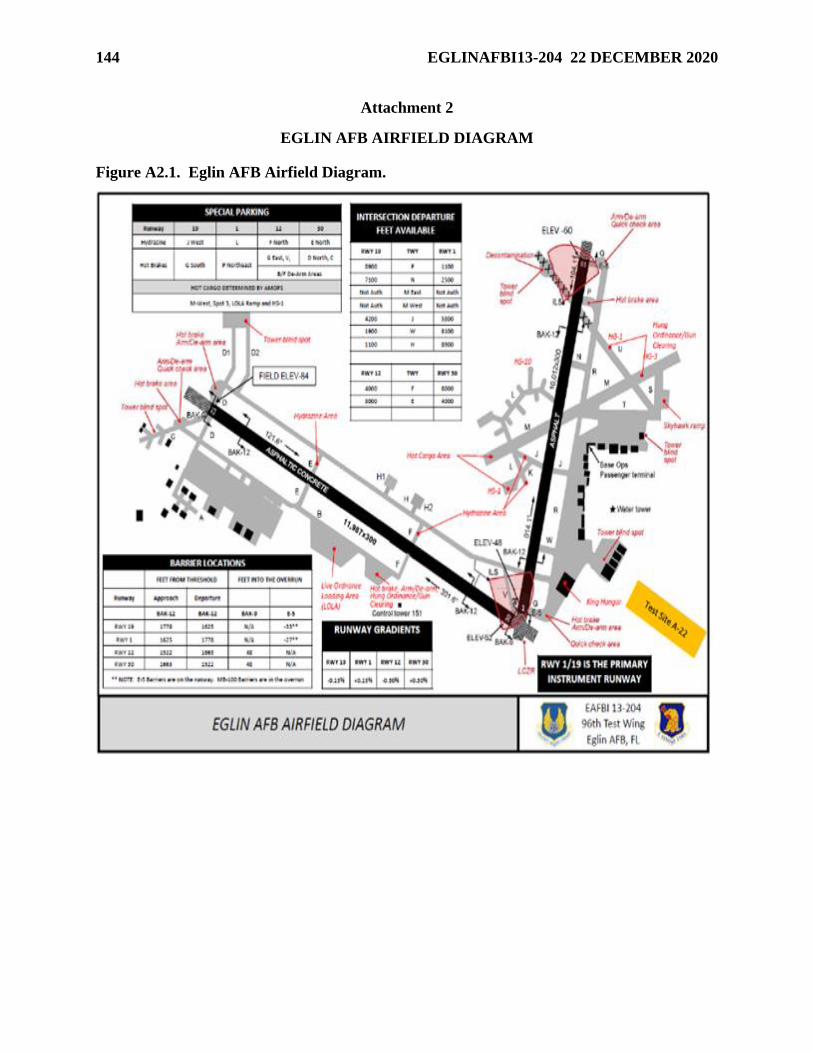
144 EGLINAFBI13-204 22 DECEMBER 2020
Attachment 2
EGLIN AFB AIRFIELD DIAGRAM
Figure A2.1. Eglin AFB Airfield Diagram.
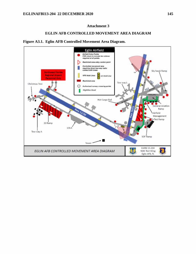
EGLINAFBI13-204 22 DECEMBER 2020 145
Attachment 3
EGLIN AFB CONTROLLED MOVEMENT AREA DIAGRAM
Figure A3.1. Eglin AFB Controlled Movement Area Diagram.
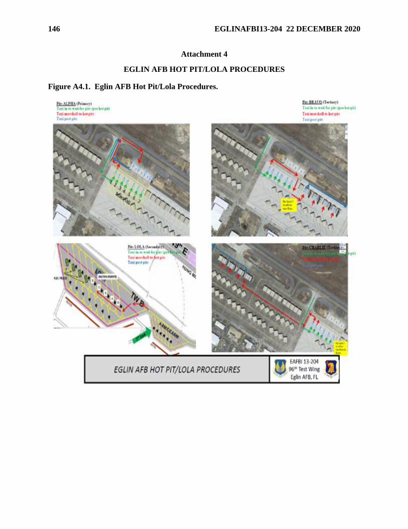
146 EGLINAFBI13-204 22 DECEMBER 2020
Attachment 4
EGLIN AFB HOT PIT/LOLA PROCEDURES
Figure A4.1. Eglin AFB Hot Pit/Lola Procedures.
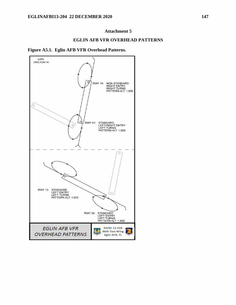
EGLINAFBI13-204 22 DECEMBER 2020 147
Attachment 5
EGLIN AFB VFR OVERHEAD PATTERNS
Figure A5.1. Eglin AFB VFR Overhead Patterns.
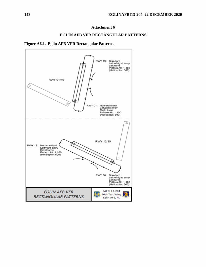
148 EGLINAFBI13-204 22 DECEMBER 2020
Attachment 6
EGLIN AFB VFR RECTANGULAR PATTERNS
Figure A6.1. Eglin AFB VFR Rectangular Patterns.
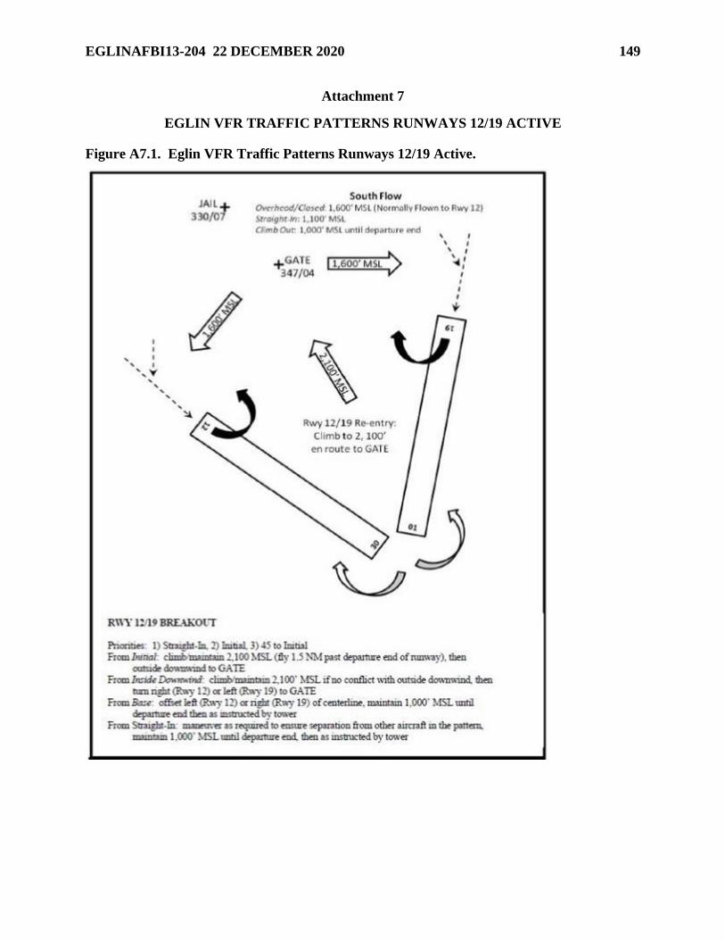
EGLINAFBI13-204 22 DECEMBER 2020 149
Attachment 7
EGLIN VFR TRAFFIC PATTERNS RUNWAYS 12/19 ACTIVE
Figure A7.1. Eglin VFR Traffic Patterns Runways 12/19 Active.
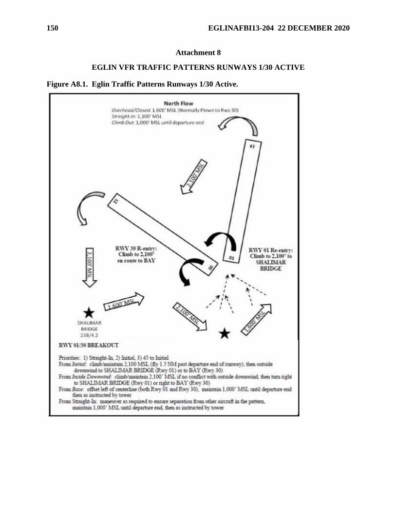
150 EGLINAFBI13-204 22 DECEMBER 2020
Attachment 8
EGLIN VFR TRAFFIC PATTERNS RUNWAYS 1/30 ACTIVE
Figure A8.1. Eglin Traffic Patterns Runways 1/30 Active.
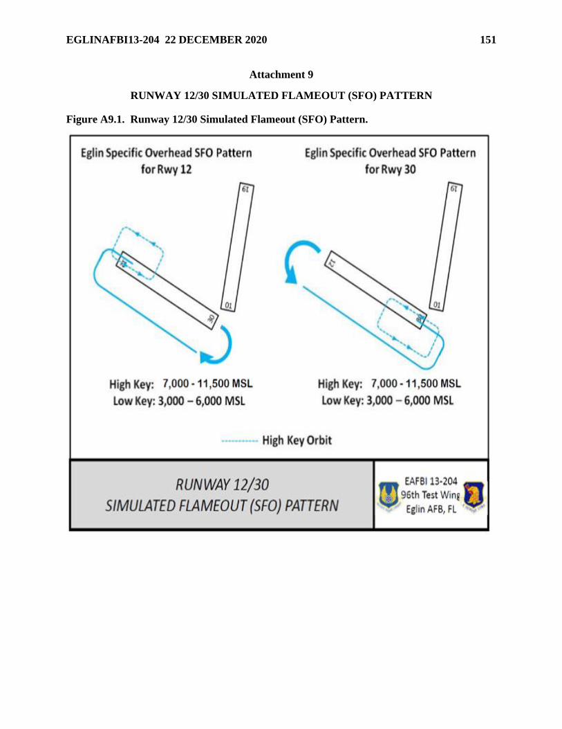
EGLINAFBI13-204 22 DECEMBER 2020 151
Attachment 9
RUNWAY 12/30 SIMULATED FLAMEOUT (SFO) PATTERN
Figure A9.1. Runway 12/30 Simulated Flameout (SFO) Pattern.
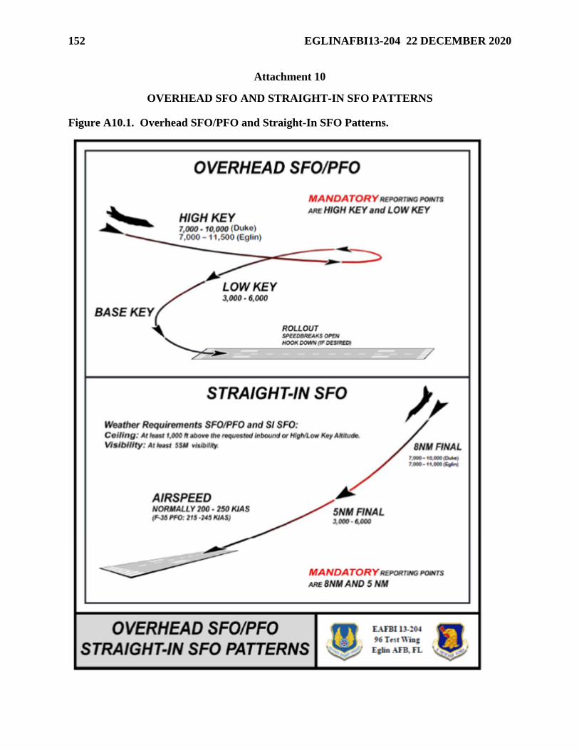
152 EGLINAFBI13-204 22 DECEMBER 2020
Attachment 10
OVERHEAD SFO AND STRAIGHT-IN SFO PATTERNS
Figure A10.1. Overhead SFO/PFO and Straight-In SFO Patterns.
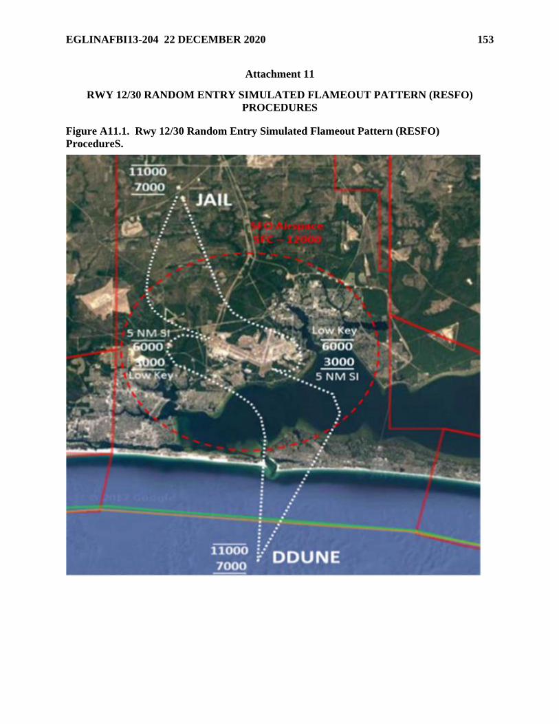
EGLINAFBI13-204 22 DECEMBER 2020 153
Attachment 11
RWY 12/30 RANDOM ENTRY SIMULATED FLAMEOUT PATTERN (RESFO)
PROCEDURES
Figure A11.1. Rwy 12/30 Random Entry Simulated Flameout Pattern (RESFO)
ProcedureS.
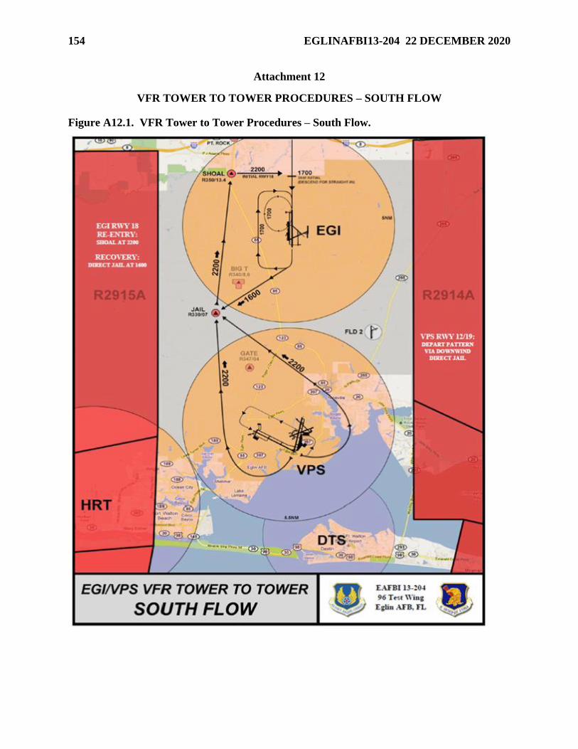
154 EGLINAFBI13-204 22 DECEMBER 2020
Attachment 12
VFR TOWER TO TOWER PROCEDURES – SOUTH FLOW
Figure A12.1. VFR Tower to Tower Procedures – South Flow.
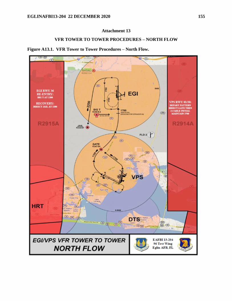
EGLINAFBI13-204 22 DECEMBER 2020 155
Attachment 13
VFR TOWER TO TOWER PROCEDURES – NORTH FLOW
Figure A13.1. VFR Tower to Tower Procedures – North Flow.
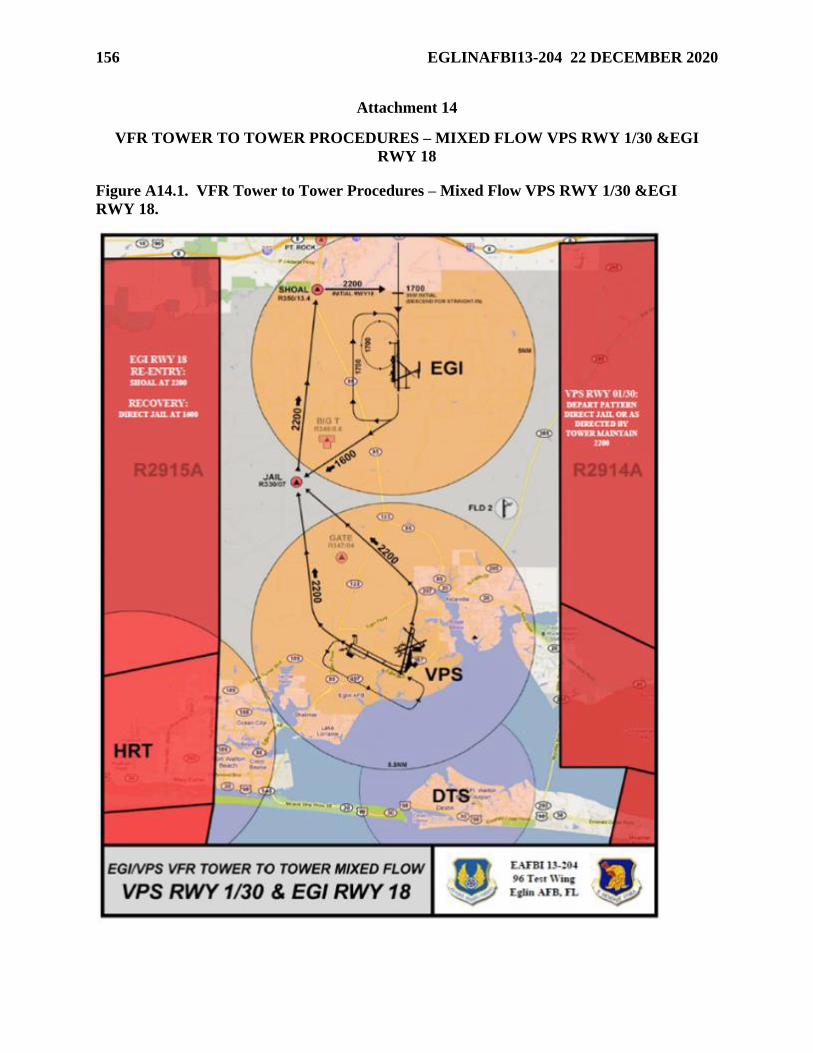
156 EGLINAFBI13-204 22 DECEMBER 2020
Attachment 14
VFR TOWER TO TOWER PROCEDURES – MIXED FLOW VPS RWY 1/30 &EGI
RWY 18
Figure A14.1. VFR Tower to Tower Procedures – Mixed Flow VPS RWY 1/30 &EGI
RWY 18.
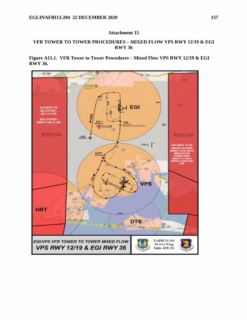
EGLINAFBI13-204 22 DECEMBER 2020 157
Attachment 15
VFR TOWER TO TOWER PROCEDURES – MIXED FLOW VPS RWY 12/19 & EGI
RWY 36
Figure A15.1. VFR Tower to Tower Procedures – Mixed Flow VPS RWY 12/19 & EGI
RWY 36.
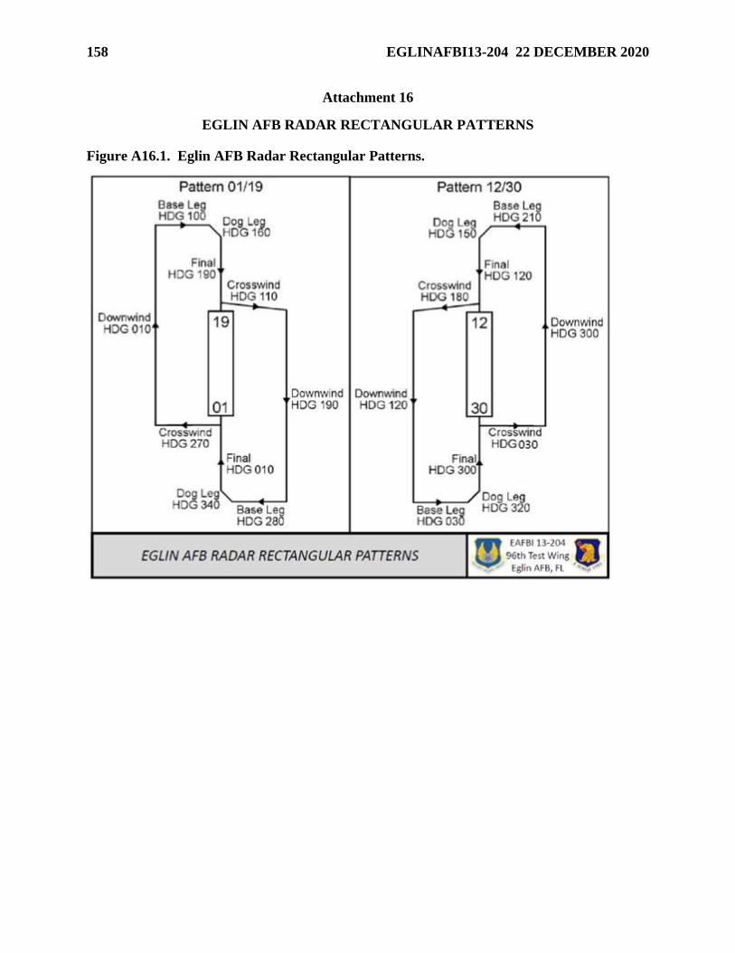
158 EGLINAFBI13-204 22 DECEMBER 2020
Attachment 16
EGLIN AFB RADAR RECTANGULAR PATTERNS
Figure A16.1. Eglin AFB Radar Rectangular Patterns.
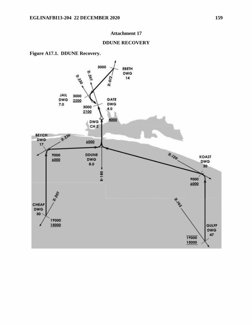
EGLINAFBI13-204 22 DECEMBER 2020 159
Attachment 17
DDUNE RECOVERY
Figure A17.1. DDUNE Recovery.
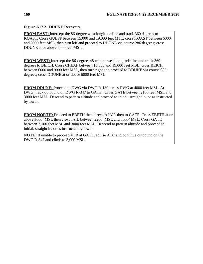
160 EGLINAFBI13-204 22 DECEMBER 2020
Figure A17.2. DDUNE Recovery.
FROM EAST: Intercept the 86-degree west longitude line and track 360 degrees to
KOAST. Cross GULFF between 15,000 and 19,000 feet MSL; cross KOAST between 6000
and 9000 feet MSL, then turn left and proceed to DDUNE via course 286 degrees; cross
DDUNE at or above 6000 feet MSL.
FROM WEST: Intercept the 86-degree, 48-minute west longitude line and track 360
degrees to BEICH. Cross CHEAF between 15,000 and 19,000 feet MSL; cross BEICH
between 6000 and 9000 feet MSL, then turn right and proceed to DDUNE via course 083
degrees; cross DDUNE at or above 6000 feet MSL
FROM DDUNE: Proceed to DWG via DWG R-180; cross DWG at 4000 feet MSL. At
DWG, track outbound on DWG R-347 to GATE. Cross GATE between 2100 feet MSL and
3000 feet MSL. Descend to pattern altitude and proceed to initial, straight in, or as instructed
by tower.
FROM NORTH: Proceed to EBETH then direct to JAIL then to GATE. Cross EBETH at or
above 3000’ MSL then cross JAIL between 2200’ MSL and 3000’ MSL. Cross GATE
between 2,100 feet MSL and 3000 feet MSL. Descend to pattern altitude and proceed to
initial, straight in, or as instructed by tower.
NOTE: If unable to proceed VFR at GATE, advise ATC and continue outbound on the
DWG R-347 and climb to 3,000 MSL
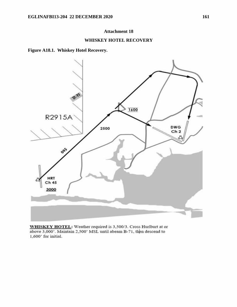
EGLINAFBI13-204 22 DECEMBER 2020 161
Attachment 18
WHISKEY HOTEL RECOVERY
Figure A18.1. Whiskey Hotel Recovery.
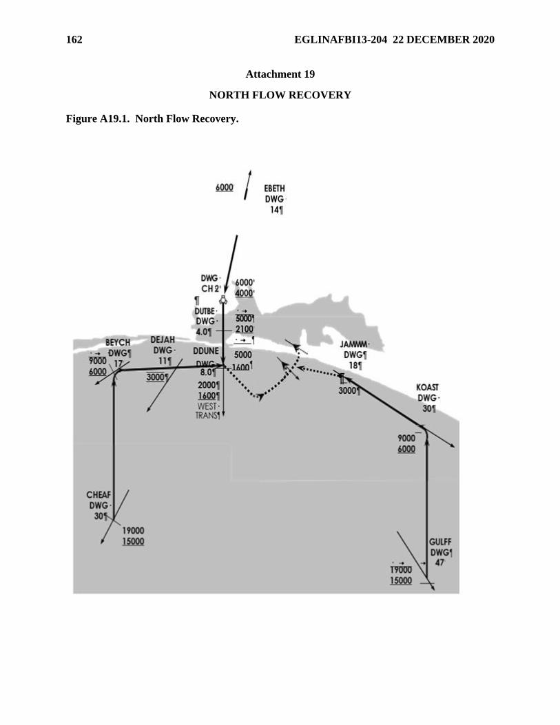
162 EGLINAFBI13-204 22 DECEMBER 2020
Attachment 19
NORTH FLOW RECOVERY
Figure A19.1. North Flow Recovery.
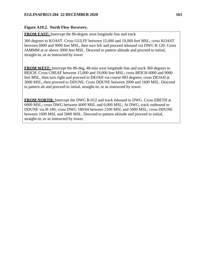
EGLINAFBI13-204 22 DECEMBER 2020 163
Figure A19.2. North Flow Recovery.
FROM EAST: Intercept the 86-degree west longitude line and track
360 degrees to KOAST. Cross GULFF between 15,000 and 19,000 feet MSL; cross KOAST
between 6000 and 9000 feet MSL, then turn left and proceed inbound via DWG R-120. Cross
JAMMM at or above 3000 feet MSL. Descend to pattern altitude and proceed to initial,
straight-in, or as instructed by tower
FROM WEST: Intercept the 86-deg, 48-min west longitude line and track 360 degrees to
BEICH. Cross CHEAF between 15,000 and 19,000 feet MSL; cross BEICH 6000 and 9000
feet MSL, then turn right and proceed to DEJAH via course 083 degrees; cross DEJAH at
3000 MSL, then proceed to DDUNE. Cross DDUNE between 2000 and 1600 MSL. Descend
to pattern alt and proceed to initial, straight-in, or as instructed by tower.
FROM NORTH: Intercept the DWG R-012 and track inbound to DWG. Cross EBETH at
6000 MSL; cross DWG between 4000 MSL and 6,000 MSL; At DWG, track outbound to
DDUNE via R-180; cross DWG 180/04 between 2100 MSL and 5000 MSL; cross DDUNE
between 1600 MSL and 5000 MSL. Descend to pattern altitude and proceed to initial,
straight-in, or as instructed by tower.
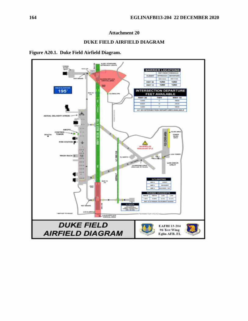
164 EGLINAFBI13-204 22 DECEMBER 2020
Attachment 20
DUKE FIELD AIRFIELD DIAGRAM
Figure A20.1. Duke Field Airfield Diagram.
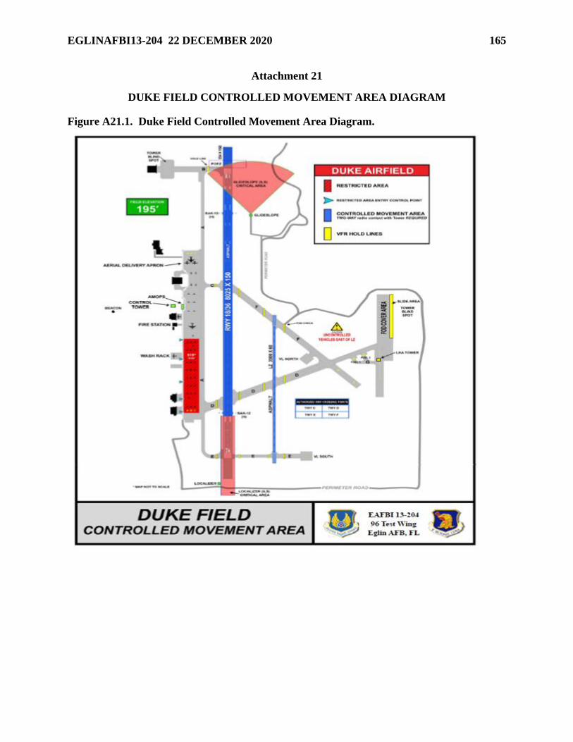
EGLINAFBI13-204 22 DECEMBER 2020 165
Attachment 21
DUKE FIELD CONTROLLED MOVEMENT AREA DIAGRAM
Figure A21.1. Duke Field Controlled Movement Area Diagram.
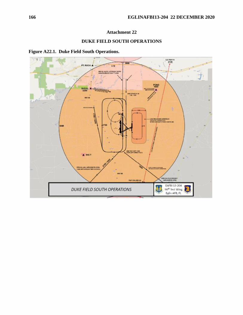
166 EGLINAFBI13-204 22 DECEMBER 2020
Attachment 22
DUKE FIELD SOUTH OPERATIONS
Figure A22.1. Duke Field South Operations.
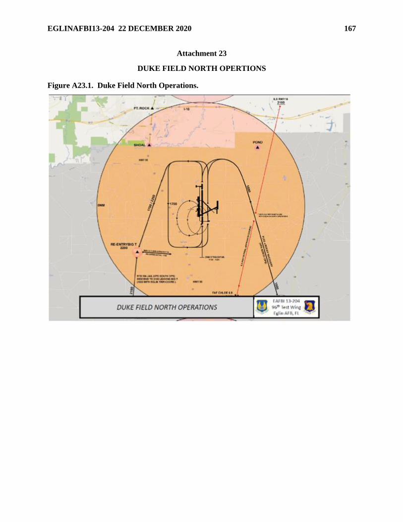
EGLINAFBI13-204 22 DECEMBER 2020 167
Attachment 23
DUKE FIELD NORTH OPERTIONS
Figure A23.1. Duke Field North Operations.
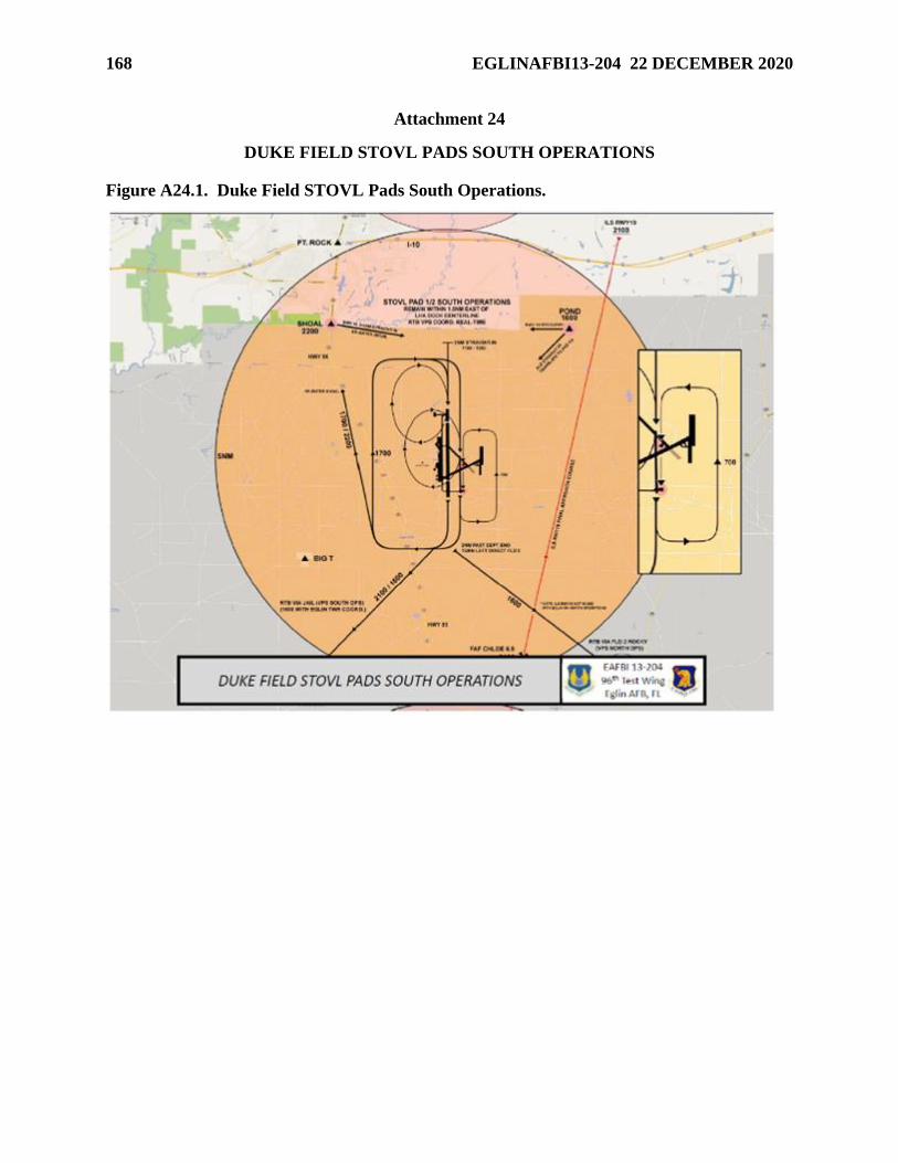
168 EGLINAFBI13-204 22 DECEMBER 2020
Attachment 24
DUKE FIELD STOVL PADS SOUTH OPERATIONS
Figure A24.1. Duke Field STOVL Pads South Operations.
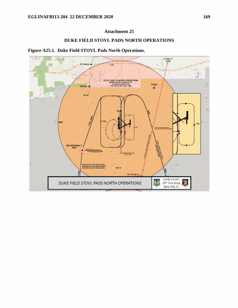
EGLINAFBI13-204 22 DECEMBER 2020 169
Attachment 25
DUKE FIELD STOVL PADS NORTH OPERATIONS
Figure A25.1. Duke Field STOVL Pads North Operations.
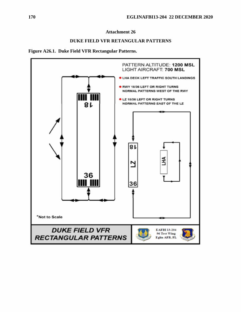
170 EGLINAFBI13-204 22 DECEMBER 2020
Attachment 26
DUKE FIELD VFR RETANGULAR PATTERNS
Figure A26.1. Duke Field VFR Rectangular Patterns.
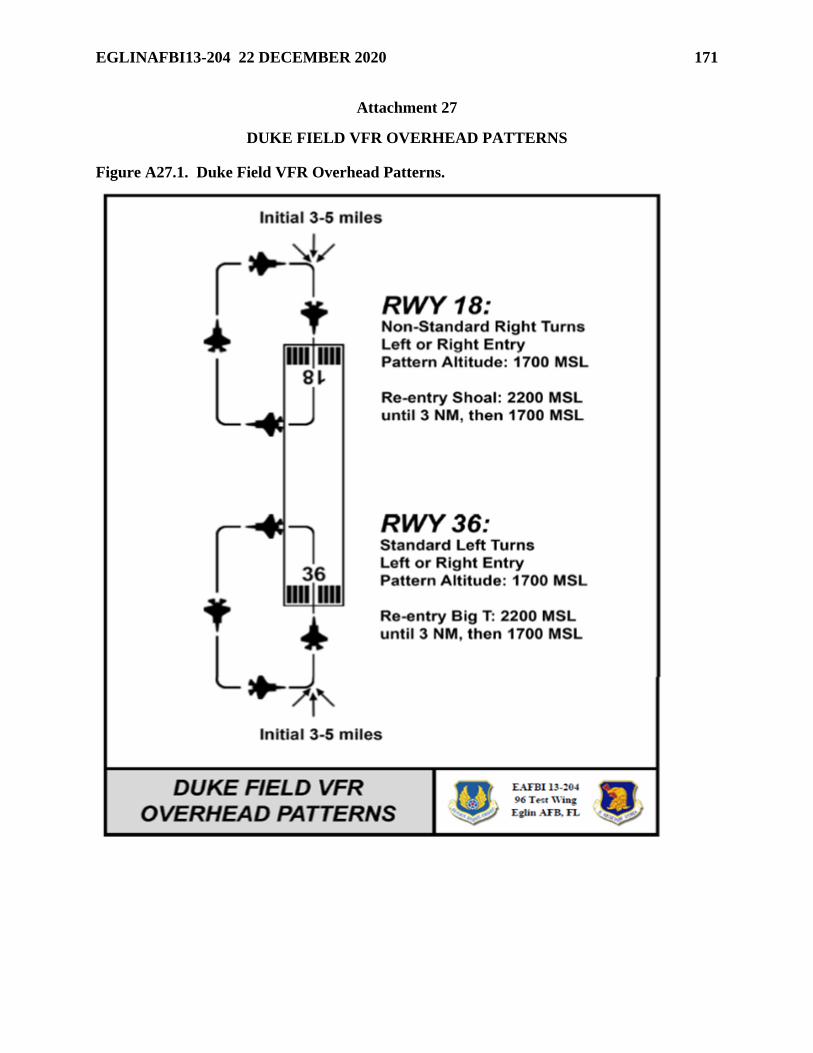
EGLINAFBI13-204 22 DECEMBER 2020 171
Attachment 27
DUKE FIELD VFR OVERHEAD PATTERNS
Figure A27.1. Duke Field VFR Overhead Patterns.
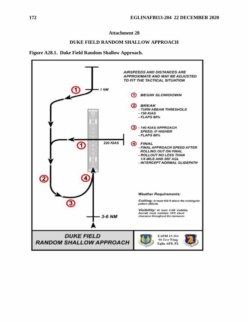
172 EGLINAFBI13-204 22 DECEMBER 2020
Attachment 28
DUKE FIELD RANDOM SHALLOW APPROACH
Figure A28.1. Duke Field Random Shallow Approach.
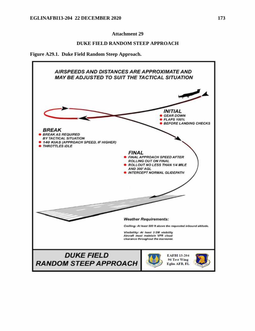
EGLINAFBI13-204 22 DECEMBER 2020 173
Attachment 29
DUKE FIELD RANDOM STEEP APPROACH
Figure A29.1. Duke Field Random Steep Approach.
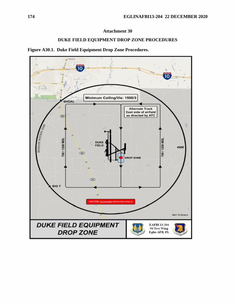
174 EGLINAFBI13-204 22 DECEMBER 2020
Attachment 30
DUKE FIELD EQUIPMENT DROP ZONE PROCEDURES
Figure A30.1. Duke Field Equipment Drop Zone Procedures.
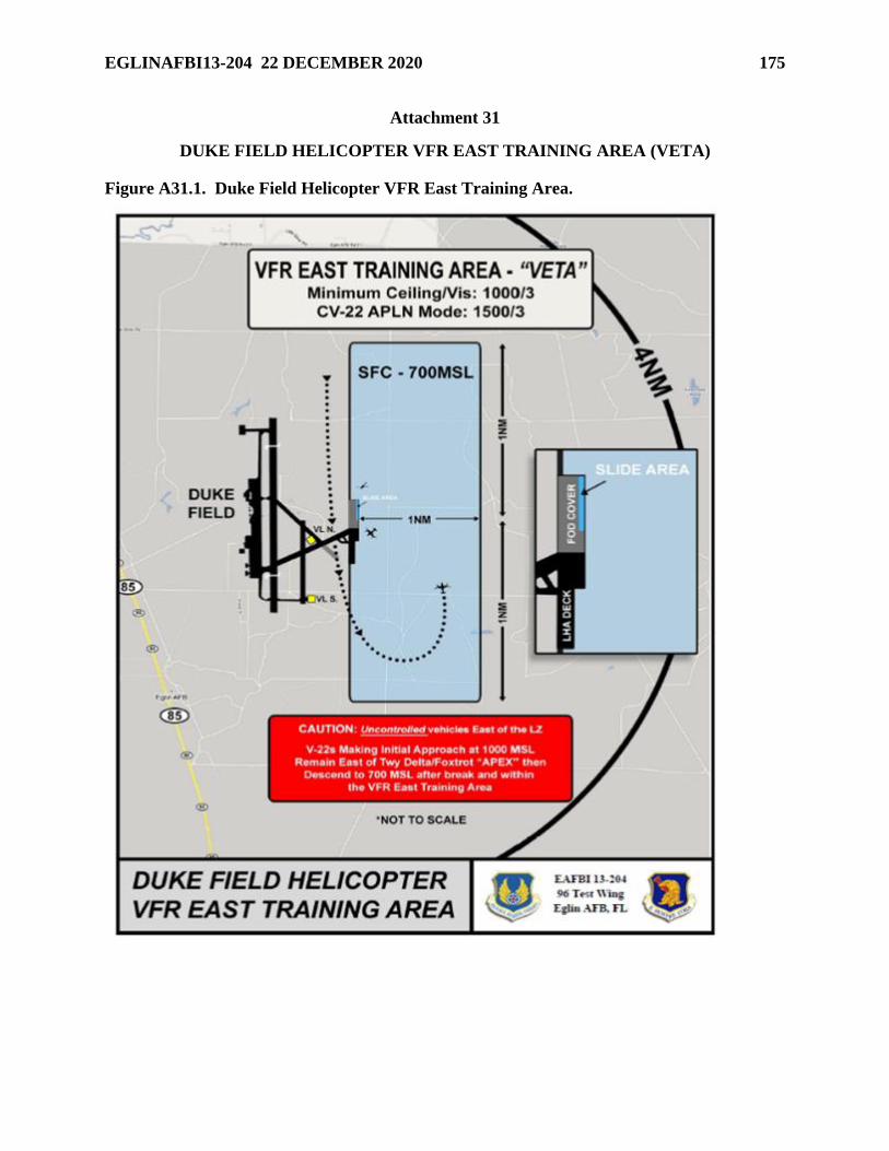
EGLINAFBI13-204 22 DECEMBER 2020 175
Attachment 31
DUKE FIELD HELICOPTER VFR EAST TRAINING AREA (VETA)
Figure A31.1. Duke Field Helicopter VFR East Training Area.
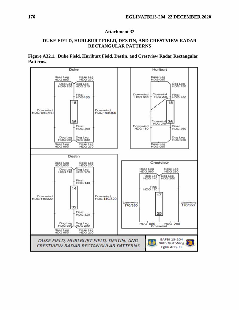
176 EGLINAFBI13-204 22 DECEMBER 2020
Attachment 32
DUKE FIELD, HURLBURT FIELD, DESTIN, AND CRESTVIEW RADAR
RECTANGULAR PATTERNS
Figure A32.1. Duke Field, Hurlburt Field, Destin, and Crestview Radar Rectangular
Patterns.
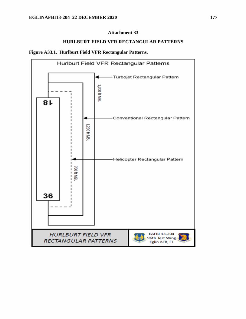
EGLINAFBI13-204 22 DECEMBER 2020 177
Attachment 33
HURLBURT FIELD VFR RECTANGULAR PATTERNS
Figure A33.1. Hurlburt Field VFR Rectangular Patterns.
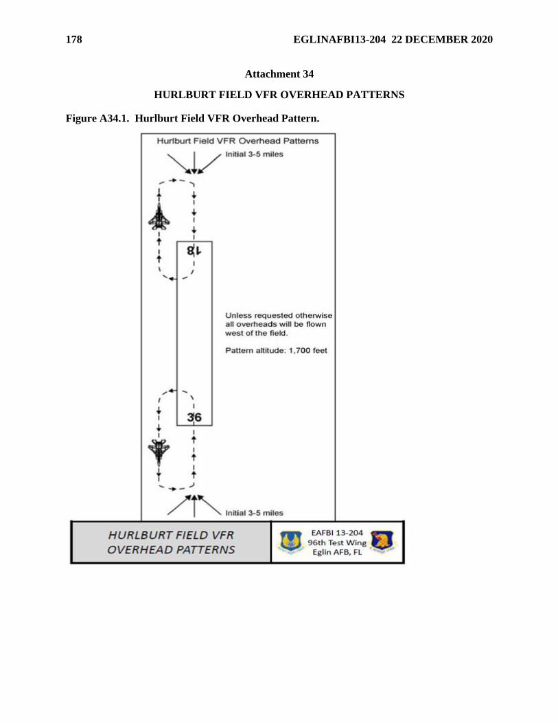
178 EGLINAFBI13-204 22 DECEMBER 2020
Attachment 34
HURLBURT FIELD VFR OVERHEAD PATTERNS
Figure A34.1. Hurlburt Field VFR Overhead Pattern.
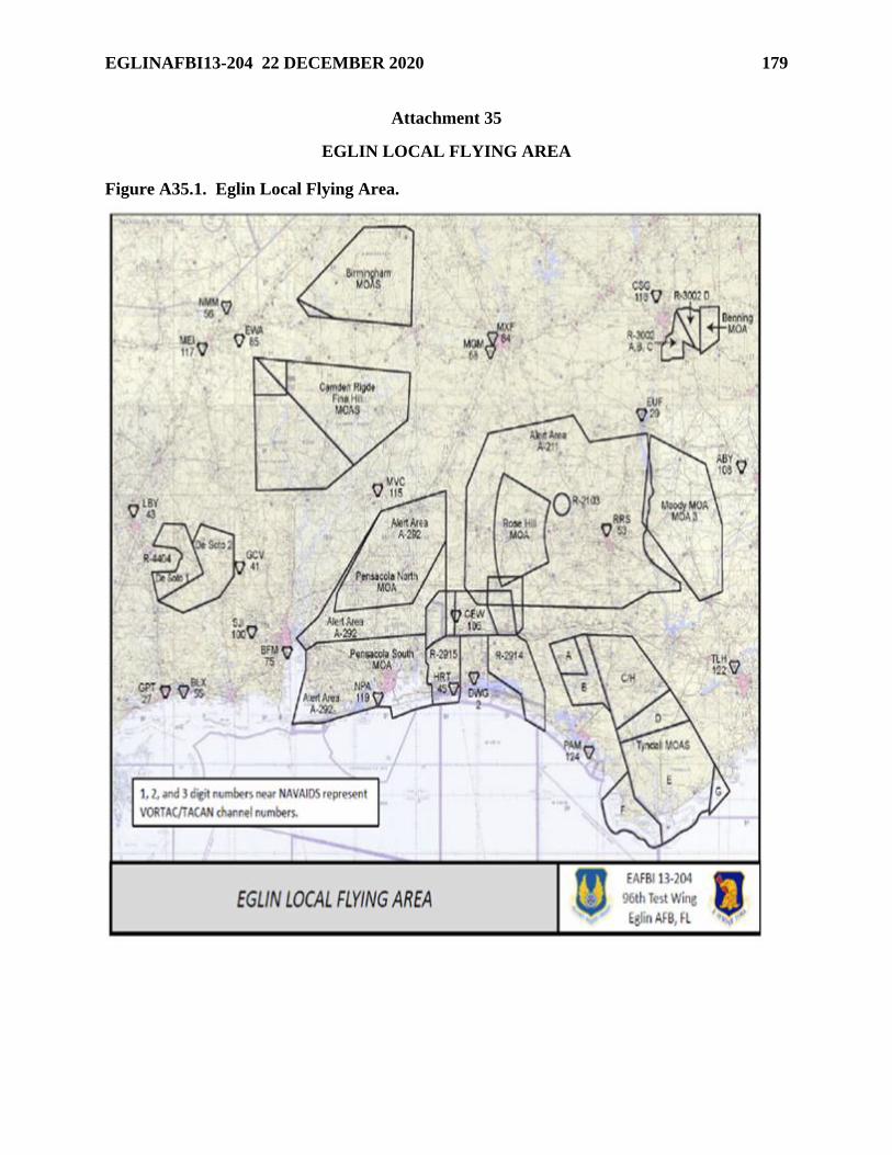
EGLINAFBI13-204 22 DECEMBER 2020 179
Attachment 35
EGLIN LOCAL FLYING AREA
Figure A35.1. Eglin Local Flying Area.
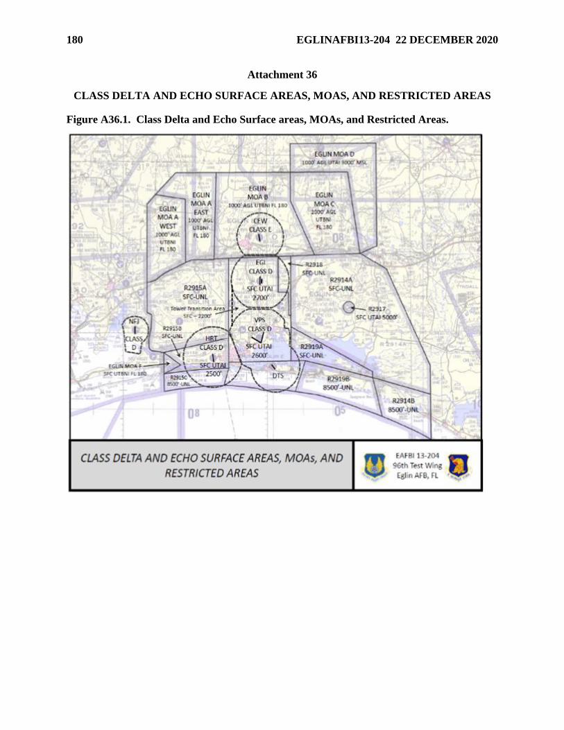
180 EGLINAFBI13-204 22 DECEMBER 2020
Attachment 36
CLASS DELTA AND ECHO SURFACE AREAS, MOAS, AND RESTRICTED AREAS
Figure A36.1. Class Delta and Echo Surface areas, MOAs, and Restricted Areas.
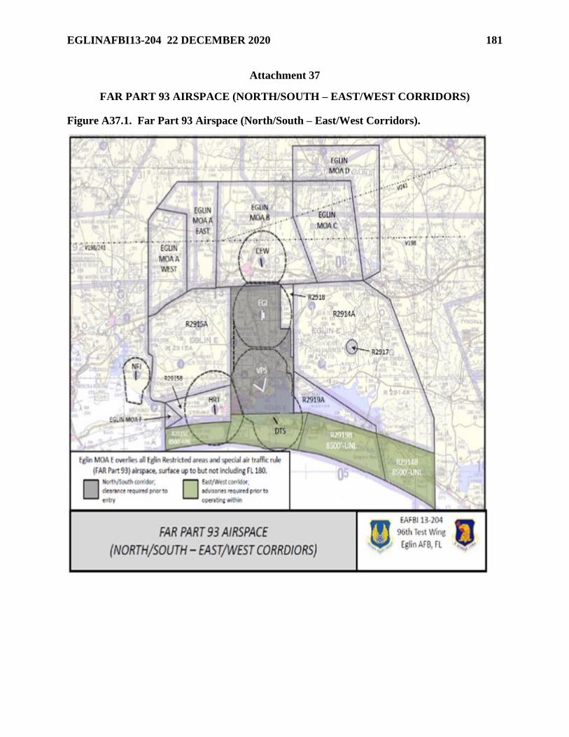
EGLINAFBI13-204 22 DECEMBER 2020 181
Attachment 37
FAR PART 93 AIRSPACE (NORTH/SOUTH – EAST/WEST CORRIDORS)
Figure A37.1. Far Part 93 Airspace (North/South – East/West Corridors).
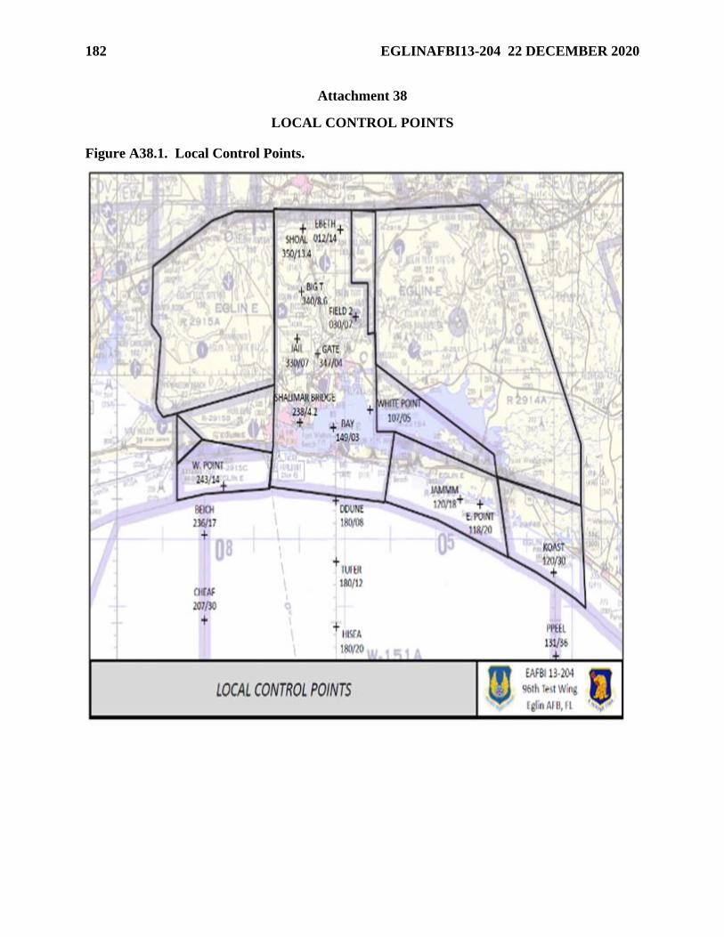
182 EGLINAFBI13-204 22 DECEMBER 2020
Attachment 38
LOCAL CONTROL POINTS
Figure A38.1. Local Control Points.
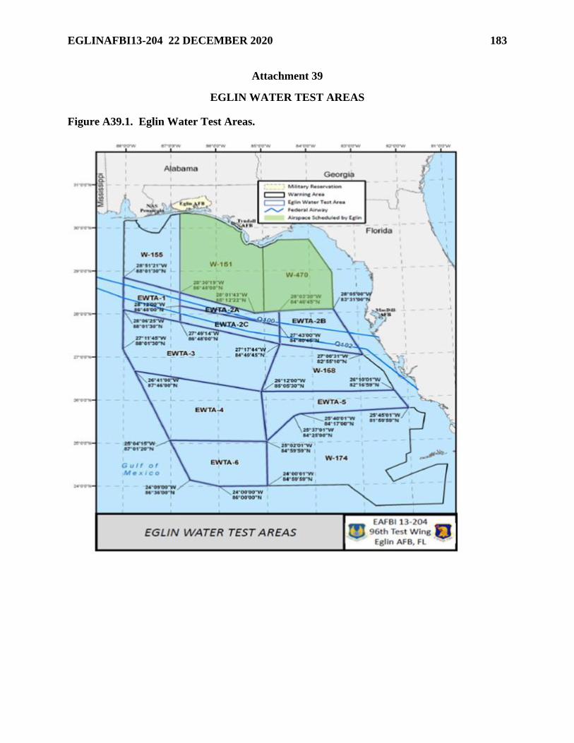
EGLINAFBI13-204 22 DECEMBER 2020 183
Attachment 39
EGLIN WATER TEST AREAS
Figure A39.1. Eglin Water Test Areas.
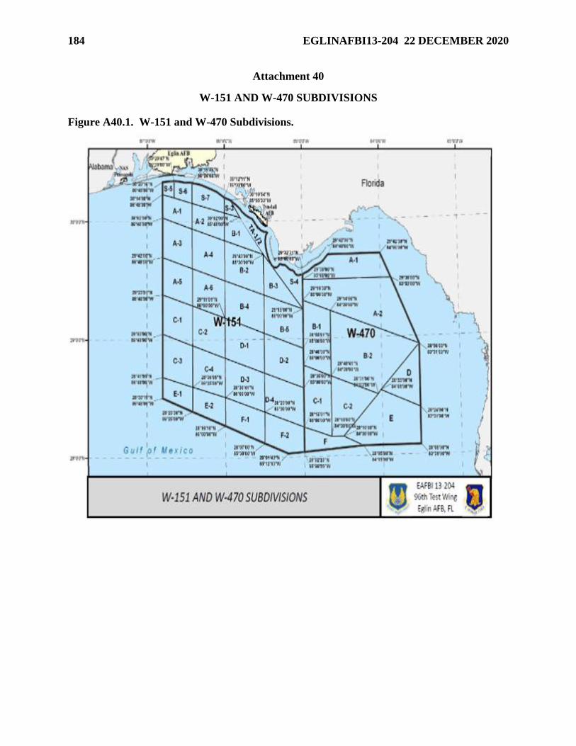
184 EGLINAFBI13-204 22 DECEMBER 2020
Attachment 40
W-151 AND W-470 SUBDIVISIONS
Figure A40.1. W-151 and W-470 Subdivisions.
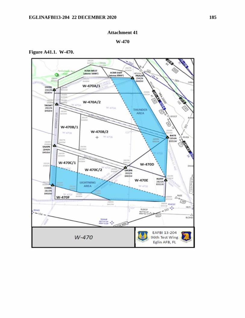
EGLINAFBI13-204 22 DECEMBER 2020 185
Attachment 41
W-470
Figure A41.1. W-470.
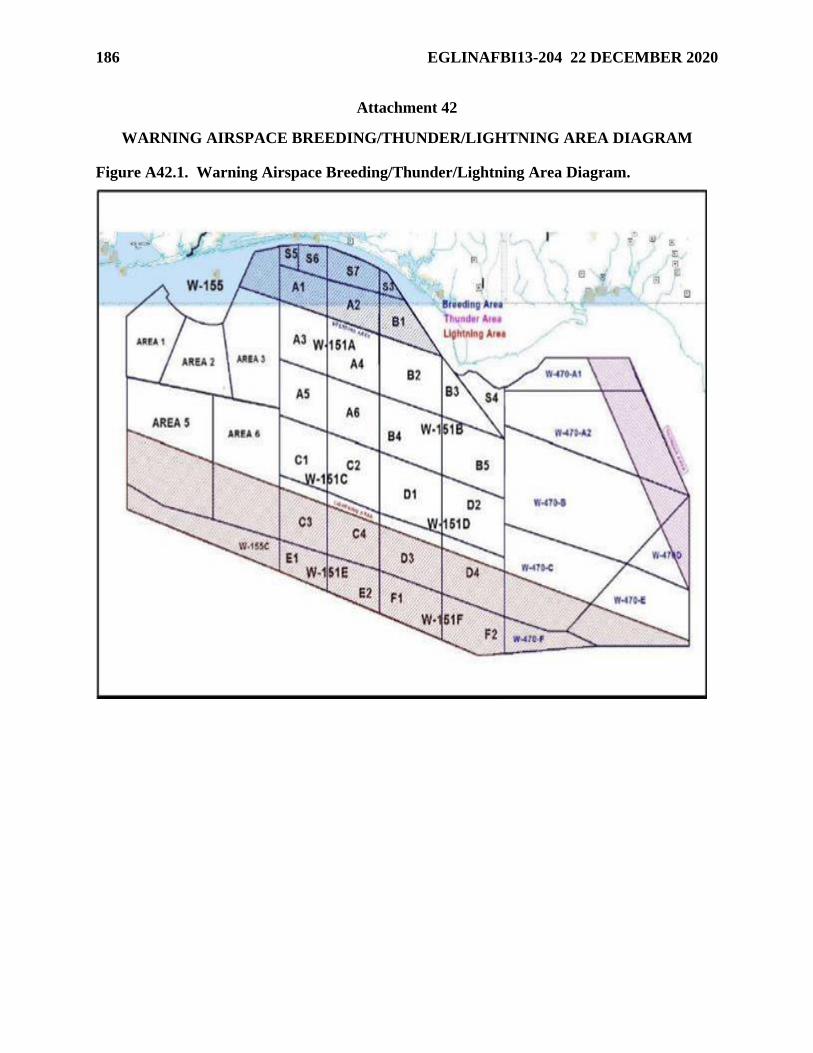
186 EGLINAFBI13-204 22 DECEMBER 2020
Attachment 42
WARNING AIRSPACE BREEDING/THUNDER/LIGHTNING AREA DIAGRAM
Figure A42.1. Warning Airspace Breeding/Thunder/Lightning Area Diagram.
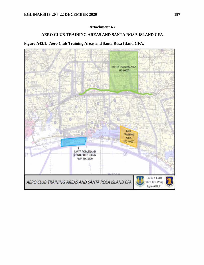
EGLINAFBI13-204 22 DECEMBER 2020 187
Attachment 43
AERO CLUB TRAINING AREAS AND SANTA ROSA ISLAND CFA
Figure A43.1. Aero Club Training Areas and Santa Rosa Island CFA.
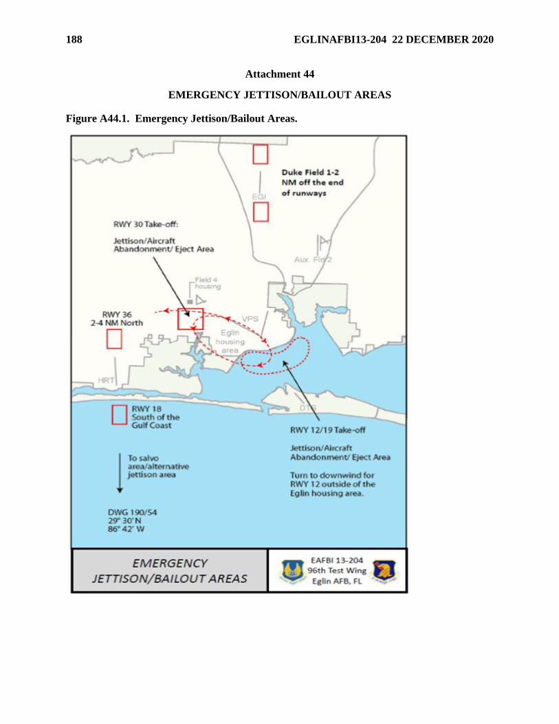
188 EGLINAFBI13-204 22 DECEMBER 2020
Attachment 44
EMERGENCY JETTISON/BAILOUT AREAS
Figure A44.1. Emergency Jettison/Bailout Areas.
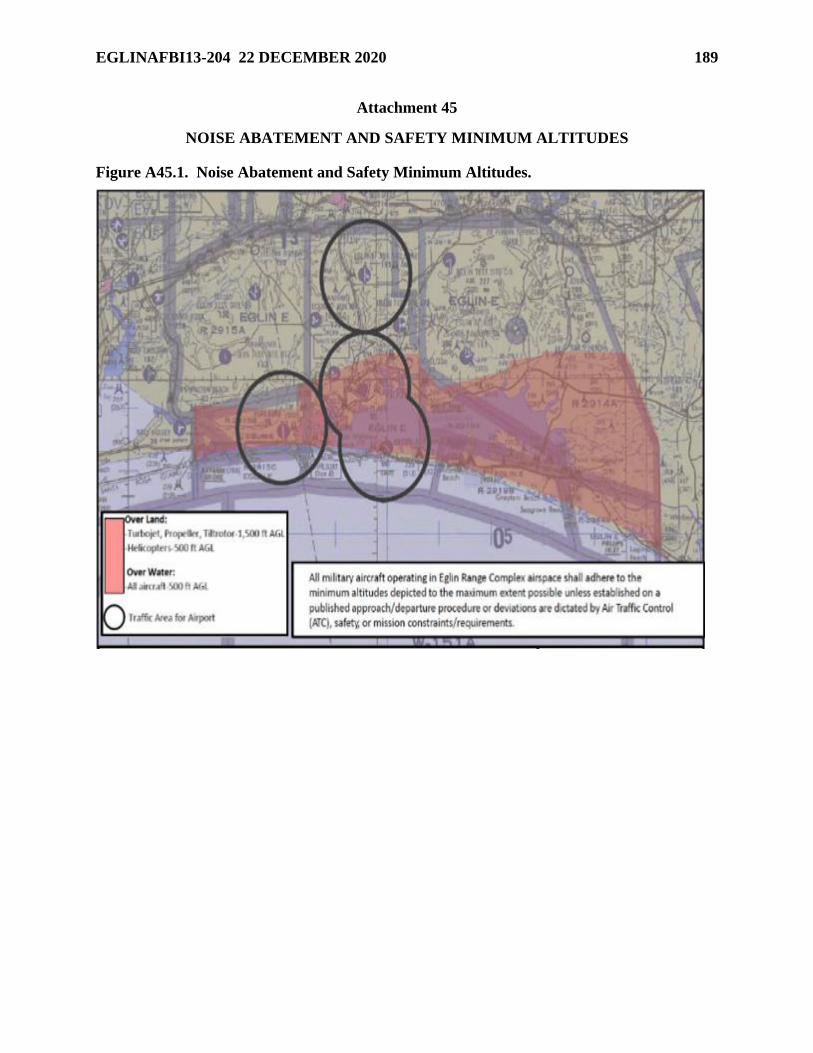
EGLINAFBI13-204 22 DECEMBER 2020 189
Attachment 45
NOISE ABATEMENT AND SAFETY MINIMUM ALTITUDES
Figure A45.1. Noise Abatement and Safety Minimum Altitudes.