BY ORDER OF THE AIR FORCE MANUAL 11-247...
117
BY ORDER OF THE SECRETARY OF THE AIR FORCE AIR FORCE MANUAL 11-247 10 APRIL 2013 Flying Operations T-1A FLYING FUNDAMENTALS COMPLIANCE WITH THIS PUBLICATION IS MANDATORY ACCESSIBILITY: Publications and forms are available on the e-Publishing website at www.e-Publishing.af.mil for downloading or ordering. RELEASABILITY: There are no releasability restrictions on this publication. OPR: AETC/A3VU Supersedes: AFMAN11-247, 4 June 2004 Certified by: AF/A3O (Maj Gen James J. Jones) Pages: 117 This publication implements AFPD 11-2, Aircrew Operations, and AFI 11-200, Aircrew Training, Standardization/Evaluation, and General Operations Structure. It contains the basic principles, procedures, and techniques applicable to all personnel operating T-1A aircraft. Air Education and Training Command (AETC) is the lead command for this manual. It applies to Air Force Reserve Command aircrew flying T-1A aircraft; it does not apply to the Air National Guard. While this manual primarily addresses the student pilot, it provides the general guidelines for all T-1A aircrew. It addresses basic flying tasks and planning considerations and is designed to be used in conjunction with AFI 112T1, Volume 1, T-1A Aircrew Training; AFI 11- 2T-1, Volume 2, T1A Aircrew Evaluation Criteria; AFI 11-2T-1, Volume 3, T-1A Operations Procedures; and technical order (TO) 1T-1A-1, Flight Manual, USAF Series T-1A Aircraft. This manual presents a solid foundation on which student training missions can be accomplished and instructor continuation training maintained. When you encounter situations not specifically covered by this publication, use safety considerations as a guide in determining the best course of action. This publication may not be supplemented. AETC/A3 is the waiver authority for this manual. Submit waiver requests in message or memorandum format, through standardization/evaluation (stan/eval) channels to AETC/A3V. Submit suggested changes to this manual on AF Form 847, Recommendation for Change of Publication, through stan/eval channels to AETC/A3V, 1 F Street, Suite 2, Randolph AFB TX 78150-4325. (AF Form 847 is prescribed by AFI 11-215, USAF Flight Manual Program (FMP). Refer to that publication for guidance on filling out the form.)
Transcript of BY ORDER OF THE AIR FORCE MANUAL 11-247...

BY ORDER OF THE
SECRETARY OF THE AIR FORCE
AIR FORCE MANUAL 11-247
10 APRIL 2013
Flying Operations
T-1A FLYING FUNDAMENTALS
COMPLIANCE WITH THIS PUBLICATION IS MANDATORY
ACCESSIBILITY: Publications and forms are available on the e-Publishing website at
www.e-Publishing.af.mil for downloading or ordering.
RELEASABILITY: There are no releasability restrictions on this publication.
OPR: AETC/A3VU
Supersedes: AFMAN11-247, 4 June 2004
Certified by: AF/A3O
(Maj Gen James J. Jones)
Pages: 117
This publication implements AFPD 11-2, Aircrew Operations, and AFI 11-200, Aircrew
Training, Standardization/Evaluation, and General Operations Structure. It contains the basic
principles, procedures, and techniques applicable to all personnel operating T-1A aircraft. Air
Education and Training Command (AETC) is the lead command for this manual. It applies to Air
Force Reserve Command aircrew flying T-1A aircraft; it does not apply to the Air National
Guard. While this manual primarily addresses the student pilot, it provides the general
guidelines for all T-1A aircrew. It addresses basic flying tasks and planning considerations and is
designed to be used in conjunction with AFI 112T1, Volume 1, T-1A Aircrew Training; AFI 11-
2T-1, Volume 2, T1A Aircrew Evaluation Criteria; AFI 11-2T-1, Volume 3, T-1A Operations
Procedures; and technical order (TO) 1T-1A-1, Flight Manual, USAF Series T-1A Aircraft.
This manual presents a solid foundation on which student training missions can be accomplished
and instructor continuation training maintained. When you encounter situations not specifically
covered by this publication, use safety considerations as a guide in determining the best course of
action.
This publication may not be supplemented. AETC/A3 is the waiver authority for this manual.
Submit waiver requests in message or memorandum format, through standardization/evaluation
(stan/eval) channels to AETC/A3V. Submit suggested changes to this manual on AF Form 847,
Recommendation for Change of Publication, through stan/eval channels to AETC/A3V, 1 F
Street, Suite 2, Randolph AFB TX 78150-4325. (AF Form 847 is prescribed by AFI 11-215,
USAF Flight Manual Program (FMP). Refer to that publication for guidance on filling out the
form.)
2 AFMAN11-247 10 APRIL 2013
Ensure that all records created as a result of processes prescribed in this publication are
maintained in accordance with Air Force Manual (AFMAN) 33-363, Management of Records,
and disposed of in accordance with Air Force Records Information Management System
(AFRIMS) Records Disposition Schedule (RDS). The use of the name or mark of any specific
manufacturer, commercial product, commodity, or service in this publication does not imply
endorsement by the Air Force. Attachment 1 contains a list of references and acronyms used
throughout the publication.
SUMMARY OF CHANGES
This document has been substantially revised and must be completely reviewed. Major
changes include: guidance for jump seat crew member (paragraph 1.3.5); inoperative intercom
(paragraph 1.7.3); PM clearing duties defined (paragraph 1.17.2); Rewords paragraphs where
needed to address CSO operations and seat positions; Traffic pattern stall recovery procedures
(paragraph 3.4.5); slow flight turns (paragraph 3.6.4); unusual attitude recovery (paragraph
3.7.4); pattern break-out procedures (paragraph 4.4); straight-in procedures from a pattern
break-out (paragraph 4.4.8); tactical pattern from a pattern break-out (paragraph 4.6.1);
configuration verbiage for tactical pattern figure 4.3 and (paragraph 4.6.5.2); standardized
verbiage for zero flap touch-and-go landings (paragraph 4.11.1); touch-and-go go-around
procedure (paragraph 4.12.1.2); practice single-engine missed approach (paragraph 4.12.3.1);
taxiing (paragraph 5.3); instrument takeoff emergency return (paragraph 6.2.3); summary of
power settings and airspeeds Table 6.1 revised; Low Level lost wingman (paragraph 8.7.2.4);
Cell Lead responsibilities (paragraph 8.13.1.1 & 8.13.1.3); Table 8.1 expanded; blind
procedures (paragraph 8.2.3.2); Position change (paragraph 8.15.2); Breakout procedures
clarified (paragraph 8.16.3); VFR Formation Tactical Overhead Pattern Entry (paragraph
8.17.3); IFR or VFR straight in drag (paragraph 8.17.4); Formation Emergencies (paragraph
8.18); Formation Communications (paragraph 8.19); ARCT (paragraph 9.1.3); Rendezvous
Procedures (paragraph 9.8.3); Alternate Rendezvous procedures (paragraph 9.8.4); Overrun
procedures (paragraph 9.10.1 & 9.10.3); receiver pre-contact to contact (paragraph 9.13.1 &
2); breakaway maneuver (paragraph 9.15.2); low level preflight coordination (paragraph
10.4); modified contour method (paragraph 10.12.12.2 & 10.12.13); turn point procedures
(paragraph 10.16.5); low level emergencies (paragraph 10.20.3 – 10.20.5); airdrop maneuver
(paragraph 10.31.2); escape (paragraph 10.32); airdrop maneuver (paragraph 10.37); low
level VMC route abort (paragraph 10.43.1 & 10.43.2)
Chapter 1—GENERAL INFORMATION 10
1.1. Overview. ............................................................................................................... 10
1.2. Airmanship and Situational Awareness. ................................................................ 10
1.3. Cockpit/Crew Resource Management (CRM): ...................................................... 10
1.4. Prior Training Comparison: ................................................................................... 11
1.5. Composite Flight. ................................................................................................... 11
1.6. Safety: .................................................................................................................... 11
1.7. Transfer of Aircraft Control. .................................................................................. 12

AFMAN11-247 10 APRIL 2013 3
1.8. Seat Swap. .............................................................................................................. 13
1.9. Preflight Briefing. .................................................................................................. 13
1.10. Preflight. ................................................................................................................ 13
1.11. Instrument Cockpit Check. .................................................................................... 13
1.12. Ground Operations: ................................................................................................ 13
1.13. Ground and In-Flight Checks. ................................................................................ 14
1.14. Taxiing: .................................................................................................................. 14
1.15. Takeoff and Landing Data (TOLD): ...................................................................... 14
1.16. Area Orientation. ................................................................................................... 14
1.17. Clearing: ................................................................................................................. 14
1.18. Radio Procedures: .................................................................................................. 15
Chapter 2—TAKEOFF, CLIMB, AND LEVEL-OFF 16
2.1. Preflight. ................................................................................................................ 16
2.2. Takeoff Options: .................................................................................................... 16
Figure 2.1. Takeoff Rotation. ................................................................................................... 17
2.3. Climb: .................................................................................................................... 18
2.4. Leveloff: ................................................................................................................. 18
Chapter 3—TRANSITION 19
3.1. Basic Maneuvers: ................................................................................................... 19
3.2. Turns: ..................................................................................................................... 19
Figure 3.1. Thirty-Degree (30o) AOB Visual Reference. ........................................................ 20
Figure 3.2. Forty-Five-Degree (45o) AOB Visual Reference. ................................................. 20
3.3. Flight Characteristics Demonstrations: .................................................................. 21
3.4. Traffic Pattern Stalls and Approach-to-Stall Parameters: ...................................... 22
3.5. Traffic Pattern Stalls and Approach-to-Stall Procedures: ...................................... 24
3.6. Slow-Flight Parameters. ......................................................................................... 24
3.7. Unusual Attitudes. ................................................................................................. 25
Chapter 4—TRAFFIC PATTERNS AND LANDINGS 27
4.1. Visual Approach Guidance: ................................................................................... 27
4.2. Approach Speed (Vapp): ........................................................................................ 27
Figure 4.1. Minimum Speeds for Pattern and Landing Operations. ......................................... 28
4.3. Wind Analysis: ...................................................................................................... 28

4 AFMAN11-247 10 APRIL 2013
4.4. Pattern Break-out Procedures: ............................................................................... 28
4.5. Straight-In Pattern: ................................................................................................. 28
Figure 4.2. VFR Straight-In Pattern. ........................................................................................ 29
4.6. Rectangular Pattern: ............................................................................................... 30
4.7. Tactical Pattern: ..................................................................................................... 31
Figure 4.3. Tactical Pattern. ..................................................................................................... 32
4.8. VFR Closed Pattern (Rectangular or Tactical): ..................................................... 33
4.9. Normal Landings: .................................................................................................. 33
4.10. No-Flap Landings: ................................................................................................. 34
4.11. Single-Engine Landings: ........................................................................................ 34
4.12. Touch-and-Go Landings: ....................................................................................... 35
4.13. Go-Around: ............................................................................................................ 35
4.14. Pattern and Landing Irregularities: ........................................................................ 36
Chapter 5—NIGHT FLYING 38
5.1. Spatial Disorientation: ........................................................................................... 38
5.2. Inspections and Checks: ......................................................................................... 38
5.3. Taxiing. .................................................................................................................. 39
5.4. Takeoff. .................................................................................................................. 39
5.5. Night Operations: ................................................................................................... 39
5.6. Traffic Patterns. ..................................................................................................... 39
Chapter 6—INSTRUMENT FLYING 41
6.1. Instrument Cross-Check. ........................................................................................ 41
6.2. Instrument Takeoff: ............................................................................................... 41
6.3. Instrument Departure: ............................................................................................ 41
6.4. Leveloff: ................................................................................................................. 42
6.5. Change of Airspeed. .............................................................................................. 42
6.6. Turns. ..................................................................................................................... 42
6.7. Climbs and Descents. ............................................................................................. 43
6.8. Vertical-S Maneuvers: ........................................................................................... 43
Table 6.1. Summary of Power Settings and Airspeeds. .......................................................... 43
6.9. IFR Unusual Attitudes. .......................................................................................... 44
6.10. Course and Arc Intercepts and Fix-to-Fix Navigation: .......................................... 44
6.11. Holding. ................................................................................................................. 45

AFMAN11-247 10 APRIL 2013 5
6.12. Jet Penetrations and Descents. ............................................................................... 45
6.13. Instrument Approaches: ......................................................................................... 46
6.14. Transition to Landing: ........................................................................................... 47
6.15. Circling Approach: ................................................................................................ 48
6.16. Missed Approach: .................................................................................................. 48
6.17. Flight Management System (FMS): ....................................................................... 48
6.18. Electronic Flight Instrument System (EFIS). ......................................................... 49
Chapter 7—NAVIGATION 50
7.1. Requirements. ........................................................................................................ 50
7.2. Preflight Planning and Briefing: ............................................................................ 50
7.3. Ground Operations: ................................................................................................ 50
7.4. Departure: .............................................................................................................. 51
7.5. En Route: ............................................................................................................... 51
Figure 7.1. Sample AF Form 70, Pilot’s Flight Plan and Flight Log. ...................................... 52
7.6. Arrival and Landing: .............................................................................................. 53
Figure 7.2. Visual Effect of a Wide Runway. .......................................................................... 55
Chapter 8—FORMATION 56
8.1. Overview: ............................................................................................................... 56
8.2. Responsibilities: ..................................................................................................... 56
8.3. Briefing: ................................................................................................................. 57
8.4. Radio Procedures: .................................................................................................. 57
8.5. Visual Signals. ....................................................................................................... 58
8.6. In-Flight Checks. ................................................................................................... 58
8.7. Lost Wingman Procedures. .................................................................................... 58
Figure 8.1. Lost Wingman. ....................................................................................................... 58
Figure 8.2. Cell Formation Lost Wingman. ............................................................................. 60
Figure 8.3. Establishing IFR Separation. ................................................................................. 61
8.8. A/A TACAN. ......................................................................................................... 61
8.9. Ground Operations. ................................................................................................ 61
Figure 8.4. Runway Lineup. ..................................................................................................... 63
8.10. Takeoffs: ................................................................................................................ 64
8.11. Departure and Climbout: ........................................................................................ 65
8.12. Visual Formation: .................................................................................................. 65

6 AFMAN11-247 10 APRIL 2013
Figure 8.5. Visual Formation Position. .................................................................................... 66
Figure 8.6. Offset Position. ...................................................................................................... 67
Figure 8.7. Visual Position Turns. ............................................................................................ 68
Figure 8.8. Offset Turns. .......................................................................................................... 69
8.13. Cell Formation: ...................................................................................................... 71
Figure 8.9. Cell Formation Position. ........................................................................................ 72
Table 8.1. Wingman Turn Delay for Cell Formation. ............................................................. 72
8.14. Breakup. ................................................................................................................. 73
8.15. Position Change: .................................................................................................... 73
Figure 8.10. Position Change. .................................................................................................... 73
8.16. Breakout: ................................................................................................................ 74
8.17. Recovery: ............................................................................................................... 74
Figure 8.11. Formation Downwind Entry. ................................................................................. 75
Figure 8.12. Pitchout Rollout Interval. ....................................................................................... 76
Figure 8.13. Landing Interval. .................................................................................................... 77
8.18. Formation Emergencies. ........................................................................................ 77
8.19. Formation Communications. .................................................................................. 78
Chapter 9—AIR REFUELING 79
9.1. Mission Planning. .................................................................................................. 79
Figure 9.1. Required Reporting Points for Air Refueling Track 001 (East). ........................... 79
9.2. Military Assumes Responsibility for Separation of Aircraft (MARSA). .............. 80
9.3. Navigation: ............................................................................................................. 80
Table 9.1. Timing Chart (No Wind). ...................................................................................... 81
9.4. Weather Radar: ...................................................................................................... 81
9.5. Cockpit Configuration: .......................................................................................... 81
9.6. Tanker Procedures: ................................................................................................ 81
Figure 9.2. Air Refueling Track. .............................................................................................. 82
Figure 9.3. Turn Range and Offset Charts. .............................................................................. 82
9.7. Receiver Procedures: ............................................................................................. 83
9.8. Rendezvous: ........................................................................................................... 84
Figure 9.4. Air Refueling Rendezvous. .................................................................................... 85
9.9. Closure Procedures: ............................................................................................... 85
Figure 9.5. Closure. .................................................................................................................. 86

AFMAN11-247 10 APRIL 2013 7
9.10. Overrun Procedures: .............................................................................................. 86
9.11. Precontact Position: ............................................................................................... 87
Figure 9.6. Precontact Position. ............................................................................................... 87
9.12. Maneuvering Requirements for the Tanker: .......................................................... 87
9.13. Receiver Procedures for Maneuvering From Precontact to Contact: ..................... 88
Figure 9.7. Contact Position. .................................................................................................... 89
9.14. Maintaining Contact Position: ............................................................................... 89
Figure 9.8. Contact Envelope. .................................................................................................. 90
9.15. Breakaway Maneuver: ........................................................................................... 90
9.16. End Air Refueling (E A/R) Point. .......................................................................... 91
Chapter 10—LOW-LEVEL NAVIGATION AND FORMATION AIRDROP 92
Section 10A—Overview 92
10.1. Mission Objective. ................................................................................................. 92
10.2. Formation Considerations: ..................................................................................... 92
Section 10B—Low-Level Navigation on a Military Training Route (MTR) 92
10.3. Purpose. .................................................................................................................. 92
10.4. Preflight Coordination. .......................................................................................... 92
10.5. Mission Planning: .................................................................................................. 92
10.6. Route Development: .............................................................................................. 93
10.7. Map-Marking. ........................................................................................................ 94
10.8. In-Flight Preparation: ............................................................................................. 94
10.9. Descent and Leveloff Procedures: ......................................................................... 95
10.10. Orbit Procedures. ................................................................................................... 96
10.11. Fuel Considerations: .............................................................................................. 96
10.12. Flying the Route: ................................................................................................... 97
10.13. Time Management Procedures: ............................................................................. 99
10.14. Course Corrections: ............................................................................................... 99
10.15. Reorientation: ......................................................................................................... 100
10.16. Turn Point Procedures. .......................................................................................... 100
10.17. Hazards at Low Level: ........................................................................................... 101
10.18. Mountainous Terrain: ............................................................................................ 101
10.19. Communication Requirements: ............................................................................. 102

8 AFMAN11-247 10 APRIL 2013
10.20. Low-Level Emergencies: ....................................................................................... 102
Section 10C—Airdrop Procedures 103
10.21. Airdrop Considerations. ......................................................................................... 103
10.22. Cockpit/Crew Resource Management (CRM). ...................................................... 103
10.23. Parameters. ............................................................................................................. 103
10.24. Mission Plan. ......................................................................................................... 103
10.25. En Route Navigation. ............................................................................................. 103
10.26. Altitude. ................................................................................................................. 103
10.27. Airspeed: ................................................................................................................ 103
Section 10D—Lead Airdrop 104
10.28. Route. ..................................................................................................................... 104
10.29. Slowdown. ............................................................................................................. 104
Figure 10.1. Slowdown. ............................................................................................................. 104
10.30. DZ Acquisition: ..................................................................................................... 104
10.31. Airdrop Maneuver: ................................................................................................ 105
Figure 10.2. Airdrop Maneuver. ................................................................................................. 105
10.32. Escape. ................................................................................................................... 105
Figure 10.3. Escape. ................................................................................................................... 106
10.33. Lead Change. ......................................................................................................... 106
10.34. Route Exit. ............................................................................................................. 106
Section 10E—Wingman Airdrop 106
10.35. Altitude. ................................................................................................................. 106
10.36. Spacing. .................................................................................................................. 106
10.37. Airdrop Maneuver. ................................................................................................. 106
10.38. Completion of Drop. .............................................................................................. 106
Section 10F—Formation Airdrop Slowdown 107
10.39. Communication Procedures. .................................................................................. 107
10.40. Slowdown Point. .................................................................................................... 107
Section 10G—Egress 107
10.41. Parameters. ............................................................................................................. 107
10.42. Procedures: ............................................................................................................. 107
Section 10H—Low-Level Route Abort Procedures 107

AFMAN11-247 10 APRIL 2013 9
10.43. Responsibilities: ..................................................................................................... 107
Section 10I—Conclusion 108
10.44. A Final Warning. ................................................................................................... 108
10.45. Preflight Planning and Briefings. ........................................................................... 108
Attachment 1—GLOSSARY OF REFERENCES AND SUPPORTING INFORMATION 109
Attachment 2—FORMATION COMMUNICATIONS 113

10 AFMAN11-247 10 APRIL 2013
Chapter 1
GENERAL INFORMATION
1.1. Overview.
1.1.1. The objective of this manual is to provide techniques and procedures to aid you in
becoming a professional military aviator. It provides the guidance to develop the skills and
attitudes learned during primary flying training and necessary to prepare you for assignments
in a wide variety of USAF aircraft. To accomplish this goal, you must attain the highest
degree of proficiency possible. This requires initiative, good judgment, trained reflexes, and
skillful flying, which come only as a result of study, practice, and determination.
1.1.2. Good study habits are essential. Every detail is important if you expect to be a safe,
professional aviator. Some important information from other directives is included in this
manual, but in no way is this information to be considered all-inclusive. The majority of the
skills and techniques you develop in training will come from your assigned instructor, other
instructors you fly with, academic instructors, and your own experiences. As you gain
experience and confidence as an aviator, you will also be developing your ability to use
sound judgment.
1.1.3. This manual and other directives are vital to flying operations. However, because of
the many different situations you will encounter as an aviator, these publications can only
provide a basis for good judgment. They do not replace it. TO 1T-1A-1, Flight Manual,
USAF Series T-1A Aircraft, contains detailed instructions for inspections, checks, and
procedures. It also provides valuable background information necessary to understand the
aircraft systems and why procedures and checks have been established.
1.1.4. This publication; AFI 11-2T-1, Volumes 1, 2 and 3; and TO 1T-1A-1 (T1A Flight
Manual) complement each other.
1.2. Airmanship and Situational Awareness. Airmanship is a learned skill involving the
consideration and evaluation of all factors that influence flying or mission accomplishment.
Good situational awareness involves keeping track of the many duties required to effectively fly
a crew-type aircraft. These duties include monitoring flight and ground conditions, tasking and
monitoring the activities of the crew, and evaluating and responding to rapidly changing
conditions. Soliciting and evaluating inputs from the crew will not only improve your airmanship
and situational awareness, but help improve the airmanship and situational awareness of the
crew.
1.3. Cockpit/Crew Resource Management (CRM):
1.3.1. Coordinating and using all available resources is essential to successful mission
accomplishment for any crew-type aircraft. CRM is the ability to make effective use of all
resources available to the crew. Effective use of the aircrew (pilot, copilot, or instructor pilot
[IP]), combat systems officer [CSO], instructor combat systems officer [ICSO], and ground
crew (air traffic controller, maintenance personnel, weather forecaster, supervisor of flying
[SOF], squadron supervisor [SUP], and others) result in better crew decisions, both on the
ground and in the air.

AFMAN11-247 10 APRIL 2013 11
1.3.2. T-1A CRM lessons concentrate on teamwork and leadership. A good crewmember
performs tasks and provides timely inputs that support successful mission accomplishment.
An aircraft commander assigns tasks that contribute to successful mission accomplishment to
each member of the crew. An aircraft commander also solicits ideas from the crew, evaluates
those ideas, and makes decisions based on those ideas. An aircraft commander encourages
the crew to make timely and appropriate inputs throughout the mission. This constant crew
interaction raises the level of situational awareness for the entire crew and enhances mission
performance.
1.3.3. The descriptions of crew actions herein are written with reference to the pilot, copilot,
and jumpseat position. For example, an IP may be occupying the right seat and, during inter-
cockpit communications or checklists, will be referred to as “copilot” based on seating
position. Additionally, because a pilot may fly from either seat, duties must be accomplished
differently depending on who has aircraft control. Therefore, references will also be made to
the pilot flying (PF) and the pilot monitoring (PM) for required actions. All pilots will fly in
all crew positions on the T1A, and it is imperative to fully understand the crew duties and
coordination process described and explained in Section IV of TO-1T-1A-1 (T-1A flight
manual).
1.3.4. Normally, the PM will not actuate controls unless directed otherwise. During
operations, the PF will call for the appropriate checklist. The PM will announce or verbalize
all checklist items and ensure correct procedures are followed for that particular step.
1.3.5. The jump seat crew member will be responsible for the following: point out any traffic
that may reasonably pose a hazard, speak up for any safety of flight concern (configuration,
speeds, clearances, etc.), back up PM for required altitude calls, be prepared with approach
plates, keep the pubs kit orderly, track number/type of landings/gear cycles, and other duties
as dictated by the AC.
1.4. Prior Training Comparison:
1.4.1. Handling Characteristics. The T-1A has some unique handling characteristics. With
the use of spoilers as flight control surfaces, the T-1A may not be as responsive in a roll as
your previous aircraft. You will also discover the control yoke is not as sensitive or as easy to
operate as a stick. As a result, the T-1A is not as responsive to control inputs. However, the
T-1A has impressive engine performance and power response.
1.4.2. Visibility. Visibility from the T-1A flight deck is restricted. Increased vigilance is
required to ensure effective clearing techniques are used.
1.5. Composite Flight. Due to an ever-present threat of bird strikes and midair collisions,
aviators must master composite-flight procedures early in their flight training. Composite flight
uses outside references supported by flight instruments to establish and maintain desired flight
attitudes and ensure the air space is clear. It enables crews to maintain precise aircraft control
while clearing for other aircraft. To establish and maintain aircraft attitude, position the nose of
the aircraft in relation to the horizon and cross-check the flight instruments to ensure desired
performance is being maintained. (See Chapter 3 for examples of T-1A visual references.) As
part of good crew coordination and flight safety, the crew should always be concentrating on
aircraft control and clearing.
1.6. Safety:

12 AFMAN11-247 10 APRIL 2013
1.6.1. Aviation safety requires use of proper procedures and good judgment. It is based on a
thorough understanding of the aircraft and good flying techniques.
1.6.2. The operating environment and weather play large roles in safety. Restricted visibility
can make clearing in the vicinity of an airfield and traffic separation very difficult. The heat
and humidity of summer months can cause additional problems to safety--reducing aircraft
performance, increasing takeoff distances, and decreasing climb rates. The heat and humidity
may also lead to fatigue and dehydration.
1.6.3. While flying the T-1A, you will have many opportunities to operate outside the
familiar home-base environment. You will encounter airfields with civilian or joint military
and civilian use. Safety requires that you complete a thorough review of all information
about the unfamiliar fields to which you will fly.
1.6.4. Your psychological condition plays an extremely important part in aviation safety.
Stress, both emotional and physical, can result from heavy training requirements, conflicts
caused by personal or family problems or relationships with supervisors and peers, and/or an
increase in individual responsibilities. You must continually evaluate your ability to perform
as a crewmember.
1.6.5. You also need to be aware of the many physiological factors affecting aviation safety.
Hyperventilation, hypoxia, and fatigue are just a few of the factors that must be understood to
be able to prevent their occurrence or minimize their effects.
1.6.6. Spatial disorientation affects a pilot’s ability to determine the actual attitude of the
aircraft. An improper instrument cross-check, failure to trust the instruments, lack of outside
visual references, rapid head movement, and/or abrupt control input movements can cause
spatial disorientation. Vertigo is one of the most common forms of spatial disorientation. The
most dangerous byproduct of vertigo is the tendency for aircrew members to believe their
body (flying by the seat-of-the-pants) instead of the instruments. As difficult as it is to do,
you must say to yourself, “The instruments are correct; fly the instruments and ignore the
body sensations.” In addition, tell the other crewmember when you are experiencing spatial
disorientation. If the other crewmember is able, do not hesitate to transfer aircraft control to
him or her (paragraph 1.7).
1.7. Transfer of Aircraft Control. An important requirement during any flight (especially
flight training) is a clear understanding of who has control of the aircraft. When piloting the
aircraft, remain on the controls until you are sure the other pilot has accepted control.
1.7.1. Hand Flying. To transfer control, the PF will inform the PM by stating, “Copilot
(Pilot), you have the aircraft.” When ready to assume control, the PM will say, “Roger,
copilot (pilot) has the aircraft.” The PF will not relinquish control until clearly hearing the
verbal response from the other pilot and seeing that the other pilot has physically taken
control. During time-critical situations, it is imperative that the PF relinquish control
immediately on the aircraft commander’s verbal command so as not to obstruct any flight
control or throttle movements.
1.7.2. Autopilot. When the autopilot is engaged, the procedure specified in paragraph 1.7.1
will be used. Ensure a positive verbal transfer, an understanding of who has control of the
aircraft, and which flight director is controlling the autopilot. However, there is no
requirement to physically take control of the yoke and throttles.

AFMAN11-247 10 APRIL 2013 13
1.7.3. Inoperative Intercom. If a verbal transfer of aircraft control is not possible (e.g.
intercom is inoperative and the crew is on oxygen) a “shake-to-take, push-to-pass” concept
will be used. The PF will alternate pushing the individual rudder pedals and point to the PM.
The PM will acknowledge with a head nod and will assume the controls with a rocking of the
yoke. The old PF will then hold up their hands to indicate relinquishing the controls.
1.8. Seat Swap. On flights with three crewmembers, the exchange of seats may be performed in
flight or on the ground in accordance with AFI 11-2T-1, Volume 3.
1.8.1. In Flight. During a noncritical phase of flight, the IP will take control of the aircraft.
The crewmember in the jumpseat will unstrap and move the seat out of the center position.
The other crew member will unstrap and move out of the pilot or copilot seat. The original
front seat crew member will now be in the jumpseat. The original jumpseat crew memberwill
take the new position in the pilot or copilot seat. At all times there will be a qualified T-1
pilot at a set of controls during a seat swap.
1.8.2. On the Ground. Taxi to an area that is clear of obstructions or traffic. Unfamiliar
aircrew should reference the local airfield diagram contained in Flight Information
Publications (FLIP). A pilot may request “progressive” taxi instructions from ground control
at a strange or unfamiliar field. The aircrew will normally accomplish the Full-Stop, Taxi-
Back Checklist. With engines in idle, the pilot will apply the parking brake and verify that
the brakes are holding. The crew will swap seats. (If only two pilots are on board, a seat swap
will not be conducted with the engines running.) When the exchange has been completed, the
crew will ready the aircraft for takeoff, using the appropriate checklists (normally the Full-
Stop, Taxi-Back Checklist and the Lineup Checklist).
1.9. Preflight Briefing. All aircrews will be briefed on their specific duties and responsibilities.
The appropriate briefing guide will be used to brief each flight or event. (See AFI 11-2T-1,
Volume 3, for mission, low-level, airdrop, and formation and air refueling briefing guides.)
Crewmembers may expand briefing guides as necessary.
1.10. Preflight. The aircraft commander will ensure complete and proper exterior and interior
preflight inspections are performed on the aircraft before each flight in accordance with the
appropriate checklist.
1.11. Instrument Cockpit Check. This check is different from other aircraft because many of
the T-1A instrument systems self-test during warmup. Also, by following the checklists, all
necessary instrument cockpit checks will be completed. (This eliminates the requirement for
performing all the steps of the instrument cockpit check as outlined in AFMAN 11-217, Volume
1, Instrument Flight Procedures.) However, you will still need to check the heading system for
the correct direction of turns during taxi and the proper heading displayed during runway
alignment.
1.12. Ground Operations:
1.12.1. For the purpose of checklist operations, the pilot in the left seat is the pilot and
thecrew member in the right seat is the copilot. The crew member in the jumpseat will
perform certain copilot duties as part of the crew coordination process IAW paragraph 1.3.5.
All checklist items will be read, and the individual responsible for each item must reply with
the appropriate response.

14 AFMAN11-247 10 APRIL 2013
1.12.2. During ground operations prior to taxi, the ground crew must be included in all
coordinated actions as directed by TO 1T-1A-1 (T-1 flight manual) checklists. The engine-
start brief to the aircrew and ground crew should include (at a minimum) normal procedures
(type and sequence of start) and emergency procedures (callouts and hand signals for any
start malfunctions and egress procedures). At other than the home station, the ground crew
should be prebriefed on the engine-start procedures (normal and emergency) and coordinated
actions for the flap check and speed brake check.
1.13. Ground and In-Flight Checks. Good checklist discipline and crew coordination are
integral parts of military flying. It is important to develop good habit patterns, which will then be
carried over to more complex aircraft. If you have any doubt about the condition, setting, or
operation necessary to perform a checklist item, ask the opinion of the aircraft commander or
other qualified personnel. During critical phases of flight, direct reference to the checklist is not
required. Do not perform after-landing checks until the aircraft is clear of the active runway.
1.14. Taxiing:
1.14.1. Stay alert and do not allow flight deck activity to distract you during taxiing. Do not
accomplish any checklist while in a congested area.
1.14.2. Taxiing is accomplished with nosewheel steering, brakes, differential power, or a
combination of all three. The nosewheel will steer in direct proportion to the amount of
rudder pedal movement. Brakes may be used at the same time to decrease the turn radius. Do
not ride the brakes while taxiing.
1.14.3. Taxi clearance requirements may be modified at your home field if established taxi
lines are marked and obstructions are either permanent or parked on established parking spot
lines. Always taxi in the center of marked taxiways unless directed otherwise by ground
control or qualified ground crew personnel.
1.15. Takeoff and Landing Data (TOLD):
1.15.1. Calculate TOLD or use approved tab data on every flight. It is imperative to know
more than just the numbers and definitions; you must have a complete understanding of the
practical application of these computations.
1.15.2. When computing TOLD before a mission, remember that forecast temperature, wind
direction and velocity, and pressure altitude may not be the same when you arrive at the
runway. Other factors, such as pilot braking technique and brake, tire, and runway
conditions, will also affect the computations. This discussion is not meant to de-emphasize
the importance of TOLD, but to point out that knowledge of what the numbers mean will
help you make decisions during an emergency on takeoff or landing.
1.15.3. Before takeoff, the PM will set the airspeed marker on S1 (decision speed), the PF
will set Vco (climbout speed), and both will memorize Vrot (rotation speed) if different than
S1.
1.16. Area Orientation. Good preflight planning and chart study make area orientation much
easier, especially if visibility is limited by weather conditions. Cross-check your chart and area
landmarks for visual flight rules (VFR) recoveries and area orientation. Additionally, use the
aircraft’s navigation equipment in case of restricted visibility or unfamiliar area assignment.
1.17. Clearing:
AFMAN11-247 10 APRIL 2013 15
1.17.1. The pilot is ultimately responsible for establishing good methods of clearing with the
crew. The T-1A methods of clearing are similar to other crew-type aircraft and require crew
coordination. With the side-by-side seating arrangement of the T-1A, the PM has limited
visibility out the PF’s side of the aircraft, just as the PF has limited visibility out the PM’s
side. This lack of visibility will require the PF to clear not only by looking out of the front
and side window, but by directing the PM to clear out their side also. The PF will direct the
crew on how to clear and challenge, “clear left (right),” as appropriate.
1.17.2. All crewmembers should listen to and cross-check the traffic alert and collision
avoidance system (TCAS) throughout the flight. They should remember, however, that
TCAS cannot depict an aircraft if its transponder is in standby or not functioning properly.
Therefore, because TCAS will not be able to display all air traffic, the crew is still
responsible for clearing visually and on the radios for other aircraft. During Practice
Instrument Approaches, the PM is clearing visually outside.
1.17.3. Aircrews operating in visual meteorological conditions (VMC) must maintain
constant vigilance for other aircraft. Radar controllers and military operating areas (MOAs)
do not relieve the crew of the responsibility to clear. Even an instrument flight rules (IFR)
clearance does not guarantee separation from all other aircraft. As the PF, ensure the crew
continues to help clear the airspace visually, on the radio, and with the use of TCAS.
1.17.4. While performing area work, the PF will clear the anticipated flightpath before
entering the next maneuver. Informing the crew of the intended maneuver and directing them
to clear in that direction will raise their level of situational awareness and allow them to help
clear the intended flightpath.
1.17.5. The crew should:
1.17.5.1. Stay clear of other locally based aircraft by being aware of areas of possible
conflict and avoiding them.
1.17.5.2. Know the location of the departure and recovery routes, flying areas, and traffic
patterns and place increased emphasis on clearing in these areas.
1.17.5.3. Listen for radio transmissions to get a feel for traffic location in the vicinity.
(The more the crew knows about the immediate flying environment, the better they will
be able to detect and avoid other aircraft.)
1.18. Radio Procedures:
1.18.1. Most radio procedures are similar to those learned in other aircraft. Local procedures,
in-flight guide (IFG), and FLIP contain specific procedures for different circumstances. In
the T-1A, crew coordination plays an important role in radio conduct. It is normally the PF’s
responsibility to direct all radio activity and the PM’s or jumpseat’s responsibility to select
the radio, set the frequencies, and do the transmitting. Remember, the T-1A has more than
one radio so it is important to select the proper unit and set the correct frequency.
1.18.2. The ultrahigh frequency (UHF) radio is used primarily for military airfields; the very
high frequency (VHF) radio is used primarily for civilian fields. Radar controllers can talk to
you on either radio. MOA radio operations will normally be conducted on UHF.

16 AFMAN11-247 10 APRIL 2013
Chapter 2
TAKEOFF, CLIMB, AND LEVEL-OFF
2.1. Preflight. Before calling for takeoff clearance, ensure you and the crew are prepared for
takeoff, all applicable procedures and checklist items have been completed, and TOLD has been
computed and posted. Because the T-1A takeoff requires crew coordination, ensure each
crewmember understands their responsibilities during and after takeoff. Before taking the
runway for takeoff, look around to make sure you are clear of all other aircraft and final is clear.
2.2. Takeoff Options:
2.2.1. Static Takeoff:
2.2.1.1. Use the brakes to hold your position during engine runup. Perform an outside
visual scan prior to and during runup to ensure the area is clear and you are not creeping
forward or pulling to one side.
2.2.1.2. Set the throttles to approximately 80 percent N1.
2.2.1.3. Verbally confirm with the PM for proper flight deck and engine instruments
indications; for example, “Engines and flight instruments checked pilot,” “Checked
copilot.”
2.2.1.4. Release both brake pedals at the same time to prevent swerving off the runway
heading at the beginning of the takeoff roll.
2.2.1.5. Maintain directional control with nose wheel steering and flight controls (yoke
and rudder) as required. Avoid differential braking because it increases the takeoff
distance. The PF must concentrate on outside references with cross-checks inside the
cockpit.
2.2.1.6. Increase the power toward the target takeoff rated thrust (TRT) N1 setting and
call, “Set power.” The PM will adjust the N1 fan speed to the computed TRT before
reaching 60 knots indicated airspeed (KIAS). The PNF should continue to guard the
throttles during the takeoff.
2.2.1.7. Passing 80 KIAS, the PM will announce “80 knots.” The engine instruments
should be in the green, indicating performance is within the normal parameters. The PF
should cross-check the airspeed indicator and acknowledge the “80 knots” call.
2.2.1.8. At S1 the PM will announce “S1,” and the PF will place both hands on the yoke
in preparation to rotate the aircraft to the takeoff attitude. The PM will continue to
monitor the engine instruments with quick outside visual checks. At Vrot, the PM will
announce, “rotate,” and the PF will apply sufficient backpressure to rotate the aircraft to a
13- to 15-degree pitch attitude for liftoff (Figure 2.1). In many situations, S1 and Vrot will
occur simultaneously. When that happens, the PM will announce “S1, rotate.”

AFMAN11-247 10 APRIL 2013 17
Figure 2.1. Takeoff Rotation.
2.2.1.9. Use caution during gusty wind conditions. Rapidly changing wind direction and
velocity require timely control inputs to ensure aircraft directional control.
2.2.2. Rolling Takeoff:
2.2.2.1. Rolling takeoffs are commonly used at airfields with heavy traffic to expedite
traffic flow and reduce runway congestion.
2.2.2.2. Compared to static takeoff performance, the rolling takeoff performance
difference is negligible. (It also has negligible effect on TOLD.) However, takeoff roll
and critical field length may increase slightly.
2.2.2.3. Before taking the active runway, the crew will accomplish all necessary checks.
A rolling takeoff and a static takeoff should be approached identically. Taxi onto the
runway in a normal manner. Once proper runway alignment is attained, the PF will
smoothly advance the throttles toward TRT and perform an engine instrument check. Do
not be in a rush to add power. As a technique, increase power from idle to TRT in
approximately 1 to 3 seconds to avoid any chance of compressor stall or overspeed. The
crew will then accomplish the remaining takeoff procedures (paragraphs 2.2.1.5
through 2.2.1.9).
2.2.3. Abort Considerations:
2.2.3.1. The most important abort consideration is to not delay making the decision to
abort. Before leaving the briefing room, the pilot should have made the decision about
when to abort a takeoff.
2.2.3.2. Aircraft weight and airspeed are important factors in an abort situation. The
heavier the aircraft and the faster the airspeed, the earlier the abort decision must be made

18 AFMAN11-247 10 APRIL 2013
because it will take longer to stop the aircraft. On touch-and-go landings, keep in mind
the airspeed and touchdown point on the runway. If you are long and fast, the distance
available for a safe abort will be decreased.
2.2.3.3. Another important abort consideration is the condition of the runway. Any
condition other than completely dry will increase the distance required to stop the
aircraft. Plan ahead. That is, before taking the runway for takeoff, reevaluate your
preplanned abort decisions and update them to match the current conditions. Runway
conditions dictate the effectiveness of braking. The better the runway conditions, the
better the braking action will be if an abort is necessary. The anti-skid system allows you
to achieve optimal braking more easily for the given runway conditions. During an actual
abort with minimal runway remaining, depress the brake pedals until the anti-skid cycles.
2.3. Climb:
2.3.1. After-Takeoff Climb:
2.3.1.1. When a positive rate of climb is established, the PF will signal for gear retraction
by making a “gear up” call. The PM will confirm positive climb and safely airborne,
repeat “gear up,” and then raise the gear handle. Ensure gear indicators reflect the UP
position. After the gear is retracted, the PM will state, “gear is up.” All crewmembers will
visually verify the gear position on the landing gear indicators. NOTE: A positive rate of
climb is established when the vertical speed indicator (VSI) and altimeter or outside
references (when available) show a climb.
2.3.1.2. Passing 400 feet (1,500 feet if required) above ground level (AGL) with a
minimum airspeed of Vco +10 KIAS, the PF will call “Flaps up, After-Takeoff (Pattern)
Checklist.” The PM will repeat “flaps up,” and raises the flaps while monitoring for any
flap asymmetry during retraction. After the flaps are up, the PM will state, “flaps are up.”
All crewmembers will visually verify the flap position on the flap indicator. Following
flap retraction, the PF will decrease pitch to 10 degrees nose up and accelerate to climb
airspeed.
2.3.2. Climb Power:
2.3.2.1. The PF will set approximate climb power. If directed, the PM will fine-tune the
throttles to climb power, normally maximum continuous thrust (MCT). Readjust N1
power to MCT approximately every 5,000 feet during the climb.
2.3.2.2. The PF will accelerate to the desired climb schedule airspeed after retracting the
flaps. Use 220 KIAS for two-engine rate climbs and 250 KIAS for two-engine range
climbs (170 KIAS for one engine climb). Maintain the climb schedule with appropriate
pitch adjustments and power adjustments for each 5,000 feet.
2.4. Leveloff:
2.4.1. Leveloff lead points are used to provide a smooth, continuous pitch change to the
level-flight attitude. Use 10 percent of the VSI for moderate climb rates. For steep climb
rates, cut the pitch in half 1,000 feet before leveloff altitude and then use 10 percent of the
VSI to complete the leveloff.
2.4.2. Leave power set at MCT to accelerate to the desired cruise airspeed. Then adjust the
power as required.

AFMAN11-247 10 APRIL 2013 19
Chapter 3
TRANSITION
3.1. Basic Maneuvers:
3.1.1. Basic Aircraft Control. Normal cruise has no unique or unusual flying
characteristics for jet transport aircraft. Aircraft control forces for a given indicated airspeed
are not affected by altitude. The only noticeable effect of altitude on flying qualities is a
decrease in dutch roll damping due to Mach effects. Above flight level (FL) 280, dutch roll
damping decreases, requiring augmented yaw damping.
3.1.2. Straight and Level. As speed increases at a constant altitude, the aircraft control
forces increase and become heavy. Therefore, while performing any flight operation or
maneuver with this aircraft, always keep it in trim.
3.1.3. Change of Power. When the aircraft is configured, its attitude is sensitive. The roll
axis can also be sensitive. During low speed flight when power is changed from idle to go-
around N1, there is an initial nose-down tendency due to the high-mounted engines. This
nose-down tendency must be counteracted. Trim should be used as power is applied to assist
in maintaining desired attitude.
3.2. Turns:
3.2.1. Normal Turns. The T-1A control system incorporates features that provide feel and
aircraft response common to large operational aircraft. The increased back pressure used to
control pitch requires additional power to maintain airspeed. The amount of additional power
required is approximately proportional to the angle of bank (AOB). The correct amount of
additional power you must add to make consistent AOB turns should remain constant
regardless of the degrees of turn. To resume level flight while rolling out of the turn, decrease
power by the same amount it was increased at the beginning of the turn to maintain airspeed.
3.2.1.1. AOB. Use shallow bank turns, 30 degrees AOB or less (Figure 3.1), for
heading changes that are less than 30 degrees. When the turn exceeds 30 degrees of
heading change, use up to 30 degrees AOB. For steep bank turns, 45 degrees is the
maximum AOB (Figure 3.2). The basic differences between normal, shallow bank, and
steep bank turns are the amount of back pressure required to maintain altitude and the
amount of power required to maintain airspeed and level flight.

20 AFMAN11-247 10 APRIL 2013
Figure 3.1. Thirty-Degree (30o) AOB Visual Reference.
Figure 3.2. Forty-Five-Degree (45o) AOB Visual Reference.
3.2.1.2. Turning Procedures. Simultaneously apply pressure to spoilers and rudder in
the direction of the desired turn. The rate of roll is determined by the amount of control
pressure applied and the rate of flight control surface displacement. Control the turn AOB
with visual sight pictures using the angular relationships of the horizon in the windscreen

AFMAN11-247 10 APRIL 2013 21
or, in instrument meteorological conditions (IMC), the AOB on the electronic attitude
direction indicator (EADI).
3.2.1.3. Pitch and Altitude. Increased nose-up pitch is required to compensate for lift
lost during turns. Only a minimum amount of increased nose-up pitch is required when
you make shallow AOB turns; greater amounts are needed as you increase the AOB. Use
the visual horizon or EADI (in IMC) references to control pitch and maintain altitude.
Correct inadvertent nose-low attitudes by reducing the AOB with coordinated spoiler and
rudder pressure while simultaneously correcting pitch with control column back pressure.
3.2.1.4. Rollout Lead Point. Rollout lead point considerations include the amount of
AOB used to make the turn and the rollout rate. The rollout lead point for a 30-degree
AOB turn is approximately 5 degrees; the rollout lead point for a 45-degree AOB turn is
approximately 10 degrees.
3.2.2. Steep Turns. Occasionally, it will be necessary to use steeper AOB than usual to
make turns, so it is necessary to understand and practice performance parameters, power
requirements, and acceleration load considerations associated with steep AOB turns.
3.2.2.1. Turning. Roll into steep AOB turns with a steady increase of bank angle. Stop
the rolling movement when you attain a 45-degree AOB indication visually or on the
EADI. Maintain a constant 45-degree AOB during the turn. Plan the lead point to roll out
on a predetermined heading. Roll out of the turn at the same rate you used to initially roll
in to the turn. Normally accomplish steep turns at speeds of 160, 200, and 230 KIAS.
3.2.2.2. Power. Power settings will vary with altitude and gross weight.
3.3. Flight Characteristics Demonstrations:
3.3.1. Asymmetric Thrust Demonstration:
3.3.1.1. Asymmetric thrust is a major cause of loss of control in large operational aircraft
experiencing engine failure or loss of thrust at low airspeeds. This demonstration will
show the significance of asymmetric thrust and effectiveness of control surfaces at both
low and high speeds.
3.3.1.2. Demonstration limit parameters will be in accordance with AFI 11-2T-1,
Volume 3. Perform the procedures twice, beginning once at 220 KIAS and then at 150
KIAS. Notice the effect of decreased airspeed on aircraft controllability. At lower
airspeeds, the aircraft fuselage no longer streamlines with the relative wind and control
effectiveness is diminished, necessitating greater control deflection. Airspeed is a
powerful aid in combating the effects of asymmetric thrust.
3.3.1.3. Ensure the aircraft is headed toward an identifiable landmark to enable the crew
to discern the effect of asymmetric thrust. While maintaining level flight, establish 220
KIAS and reduce power on both engines to idle. Then smoothly advance one throttle to
MCT. Notice the effect of the asymmetric thrust on the nose track with respect to the
landmark or horizon. The aircraft will yaw away from the operative engine, resulting in a
rolling tendency in the same direction.
3.3.1.4. After noting the effect of asymmetric thrust on the aircraft and ground track,
maintain aircraft control by using rudder opposite the direction of yaw and a bank of 5
degrees into the operative engine. The rudder counteracts the yaw and the bank reduces

22 AFMAN11-247 10 APRIL 2013
the slide slip angle, which decreases drag and improves directional control. Recover by
smoothly matching the throttles as the wings are brought level and rudder pressure is
reduced.
3.3.1.5. Repeat the demonstration at 150 KIAS. Notice the difference between the
aircraft response and control inputs required to counteract the asymmetrical thrust at the
two airspeeds.
3.3.2. Yaw Damper (YD) Failure Demonstration:
3.3.2.1. The YD will use the autopilot rudder servo to provide yaw damping and control
the adverse effects of dutch roll. You need to know how to handle the aircraft in case the
autopilot YD becomes inoperative.
3.3.2.2. The YD annunciators are on the EADI. A green YD annunciation illuminates
when the YD is engaged. A yellow YD annunciation illuminates when the YD is
disengaged and flashes for 5 seconds before disappearing from view.
3.3.2.3. When the YD is disengaged or inoperative, you will observe mild but persistent
dutch roll when you displace the aircraft from straight-and-level flight. The purpose of
the YD failure demonstration is to show you this effect.
3.3.2.4. Demonstration limit parameters will be in accordance with AFI 11-2T-1,
Volume 3. Perform the procedures separately so you can compare the aircraft reactions.
3.3.2.5. With the YD disengaged, apply sufficient rudder deflection (either to the left or
right) to displace the aircraft from straight-and-level flight. Then rapidly release the
rudder, allowing it to return to neutral. Note the oscillations without the yaw damper.
Ensure oscillations are minimized before engaging the YD. Engage the YD. Reapply
sufficient rudder deflection, rapidly release the rudder, and observe minimal oscillations.
3.3.3. Flap Retraction Demonstration:
3.3.3.1. This demonstration will illustrate the effect of the flaps on lift and drag. In the T-
1A, flaps are not only used to increase lift for the takeoff and landing phases, but also for
drag.
3.3.3.2. Demonstration limit parameters will be in accordance with AFI 11-2T-1,
Volume 3. If approach-to-stall indications are encountered any time during this
demonstration, perform the appropriate recovery procedures.
3.3.3.3. Configure the aircraft with gear, flaps to 30 degrees, and slow to Vapp (approach
speed) minus 5 knots. It is usually convenient to perform this demonstration immediately
following slow-flight practice. Once stabilized, leave the power set and retract the flaps
to the 10-degree setting while maintaining level flight. By observing the angle of attack
(AOA) and airspeed indicators, notice a slight loss in lift and a rapid increase in airspeed.
The increase in airspeed will quickly negate the loss in lift, making it difficult to observe.
Return the flaps to 30 degrees and reestablish slow-flight airspeed. Again leaving the
power set, retract the flaps to full up. Again note the change in airspeed and loss of lift,
which is more apparent than when the flaps were raised to 10 degrees. Recover from the
demonstration by performing the slow-flight recovery procedures.
3.4. Traffic Pattern Stalls and Approach-to-Stall Parameters:

AFMAN11-247 10 APRIL 2013 23
3.4.1. Before starting these maneuvers set the YD to OFF and AOA to 1.3, set the Vapp on
the airspeed indicator, calculate and set MCT on N1 indicator, and clear the area.
3.4.2. You must be able to recognize the approach-to-stall indications and the procedures to
return the aircraft to normal flight. Traffic pattern stall and approach-to-stall training
emphasizes recognition of approaching stall conditions as well as procedures used to recover
the aircraft to normal flight.
3.4.3. Actual traffic pattern stall or approach-to-stall situations frequently result from
improper aircraft handling, maneuvering, or configuration. The T-1A aircraft stall warning
system--which provides indications of approach-to-stall or stalled conditions--incorporates
control column stick shakers, an AOA indicator, and shroud panel stall warning annunciators
that receive signal information from the AOA computers.
3.4.4. The T-1A exhibits handling characteristics of moderate airframe buffet, which does
not increase appreciably at full stall, and mild rolling tendencies, which also provide
warnings of an approach-to-stall condition.
3.4.5. Initiate recovery as soon as you recognize any impending stall indication—normally
the stick shaker and/or airframe buffet. To recover from an impending stall condition:
3.4.5.1. Simultaneously relax column backpressure, roll wings level, and advance power
to Go Around N1 (Use MCT when practicing). Placing the column forward to neutral
will reduce the angle of attack and allow the aircraft to recover. Do not hesitate to
“firewall” the engines to avoid ground impact.
3.4.5.2. Do not attempt to maintain any planned pattern ground track until safely
airborne at a safe altitude and airspeed.
3.4.5.3. If flaps are 30 or 10 degrees, after advancing throttles, the PF will call for “Flaps
10, set power.” Raise the flaps UP at a minimum airspeed of Vref +20 knots. Note: If
flaps are UP, the PF will call “Flaps up, set power” and the flaps remain up. In all cases,
the PM will verify that the flaps are in the proper position and appropriate power is set.
3.4.5.4. Return to level flight as soon as possible with a minimum amount of altitude
loss. Normally, attempt to recover using approximately .8 to .85 AOA, just prior to stick
shaker. To ensure you are flying the aircraft as close to the stick shaker onset point as
practical, nibbling in and out of the stick shaker is acceptable as long as pitch changes are
not excessive. This will minimize your altitude loss while providing a safety margin
above the actual stall condition.
3.4.5.5. When safely climbing away from the ground, retract the landing gear and
continue climbing to a safe altitude. Once ground impact/obstacles are no longer a factor,
consider shallowing out your climb to gain the airspeed needed to clean up the aircraft.
You may apply normal go around procedures as part of your practice recovery
procedures. During practice stalls, the recovery is complete when the aircraft is clean (or
simulated clean), not descending, and airspeed exceeds Vref +20 knots.
3.4.6. When doing 10- or 0-degree flap stall recoveries, leave the flaps at their current
setting. If cleaning up the aircraft on the last stall series, complete the stall recovery by
raising the gear once a positive rate of climb is established.

24 AFMAN11-247 10 APRIL 2013
3.4.7. Parameters for performing practice traffic pattern stall maneuvers include using any
desired flap position and accomplishing the maneuvers in any desired sequence.
3.4.8. When you unintentionally encounter actual stall or approach-to-stall conditions in the
traffic pattern, disregard normal traffic pattern ground tracks during your recovery actions.
This is a situation where your first priority is to regain control of the aircraft. When you have
the aircraft under control, advise the tower of your situation and intentions.
3.5. Traffic Pattern Stalls and Approach-to-Stall Procedures:
3.5.1. Traffic Pattern Overshooting Final Turn Stall:
3.5.1.1. Configure for landing with gear extended and flaps set in any desired position.
Reduce power to idle and establish a simulated final turn maneuver. Simulate an
overshooting final turn using normal to steep AOBs (30 to 45 degrees), which may
require lowering the nose and/or increasing back pressure. Continue increasing control
column back pressure until you recognize an approach-to-stall indication. Refer to
paragraph 3.4.5 for recovery procedures.
3.5.2. Traffic Pattern Undershooting Final Turn Stall:
3.5.2.1. Establish landing configuration with landing gear extended and flaps in any
desired flap position. Reduce power to idle and establish a simulated final turn maneuver.
Simulate an undershooting final turn and establish a simulated descending turn to final,
using a shallow AOB (10 to 20 degrees) and a pitch attitude higher than you would
normally use in final turn maneuvers. Continue turning until you recognize the approach-
to-stall indications.
3.5.2.2. Stall airspeed is lower because of the decreased AOB. Also, recovery to level
flight requires more time because the airspeed at the beginning of acceleration is less than
it is in the nose-low final turn stall maneuver. Refer to paragraph 3.4.5 for recovery
procedures.
3.5.3. Traffic Pattern Final Approach to Stall:
3.5.3.1. Extend the landing gear and position the flaps as desired to simulate a final
approach/landing configuration. Retard the throttles to idle and establish a landing flare
attitude. Refer to paragraph 3.4.5 for recovery procedures.
3.6. Slow-Flight Parameters. You need to know the appropriate aircraft configurations for
performing slow flight, proper maneuver AOA, and its altitude limitations. This is a coordinated
flight exercise.
3.6.1. Slow-Flight Configuration. Accomplish slow-flight maneuvers with the landing
gear extended until performing the slow-flight recovery. Position the flaps in the appropriate
position required to perform the intended landing pattern maneuver. Set the AOA indicator
index reference at 1.3.
3.6.2. Slow-Flight Airspeed. Configure the aircraft and slow to Vapp -5 knots.
3.6.3. Straight-and-Level Flight. Slow the aircraft to the appropriate speed (a slightly slow
indication on the AOA indicators). Use power as required to maintain airspeed and level
flight. Trim as required to neutralize flight control surface pressures for slow-flight

AFMAN11-247 10 APRIL 2013 25
maneuvers. Control the aircraft attitude by using flight instruments and visual references and
monitor level flight deviations with the altimeter.
3.6.4. Turns. During turns, maintain altitude and airspeed with smooth power applications.
Use shallow (10 to 20 degrees) AOBs while keeping the aircraft in trim. An increased AOB
results in an increased stall speed. The AOA and power required to maintain airspeed also
increases as the AOB increases and decreases during a return to level flight after rollout.
Slow flight should normally consist of at least two turns of approximately 30 degrees of
heading change in each direction. Emphasis is on “coordinated flight” and exploring slow
flight characteristics.
3.6.5. Slow-Flight Recovery Procedures. Slow-flight recovery procedures demonstrate the
appropriate aircraft feel for recovery from a slow-speed condition encountered in the actual
traffic pattern. The recovery procedures apply to straight-and-level flight and during turns.
3.6.5.1. Initiate stall recovery procedures when you complete the practice maneuvers.
Also initiate stall recovery procedures any time you recognize an indication of the
approach-to-stall condition.
3.6.5.2. Avoid abrupt control column movement to prevent entering a stalled condition
and anticipate trim requirement changes resulting from increased power. Try to maintain
neutral control column pressure as the airspeed increases.
3.6.5.3. Retract the landing gear and flaps to improve acceleration. Do not allow the
AOA to increase above the desired slow-flight AOA during configuration changes. If
accomplishing 30-degree flap slow flight, raise the flaps to 0 degrees at a minimum
airspeed of Vref + 20 knots.
3.6.5.4. Recover the aircraft with minimum altitude loss.
3.7. Unusual Attitudes. You must be able to recognize and confirm that an unusual attitude
exists; then you must know how to recover to level flight. Exercise caution while performing
practice recoveries to avoid approaching or exceeding airspeed or G limits.
3.7.1. Parameters. Maneuver parameters will be in accordance with AFI 11-2T-1, Volume
3. Compute an MCT and use power as required, but avoid exceeding the MCT limits.
3.7.2. Recovery. An unusual attitude may be a flight attitude and airspeed where aircraft
control may be lost unless proper recovery action is initiated. The key to a successful
recovery is early recognition of an unusual attitude. Apply the appropriate recovery
procedure without delay when an unusual attitude is recognized and verified.
3.7.3. Verification:
3.7.3.1. Visual cues to determine an unusual attitude include comparing the aircraft
attitude (pitch and AOB) with the visual horizon references and standby attitude
indicator.
3.7.3.2. Excessive wind noise or the absence of normal wind noise may be a clue that an
unusual attitude exists.
3.7.3.3. Oscillation between positive and negative acceleration forces indicates the
aircraft is in uncoordinated flight.

26 AFMAN11-247 10 APRIL 2013
3.7.3.4. Instrument cues that warn you about an unusual attitude are abnormally high or
low airspeed or Mach, abnormal attitude indications on the EADI, rapidly changing flight
conditions (heading, altitude, vertical speed), and related abnormal performance
instrument indications.
3.7.4. VFR Unusual Attitude Recovery Procedures:
3.7.4.1. For a nose-high attitude recovery:
3.7.4.1.1. Assess the aircraft attitude and determine what corrections are needed to
return to level-flight attitude. If the airspeed is low, add power to MCT if necessary.
3.7.4.1.2. Decrease pitch by relaxing back pressure and rolling toward the nearest
horizon without exceeding 45 degrees AOB. Roll wings level when the nose reaches
a level flight pitch picture.
3.7.4.1.3. If airspeed is low, you may want to allow the nose to continue below the
horizon to increase airspeed. Use caution if at low altitude.
3.7.4.2. For a nose-low attitude recovery:
3.7.4.2.1. Assess the aircraft attitude and determine what attitude corrections are
needed to return to level flight. Determine if an airspeed limit is a critical recovery
consideration.
3.7.4.2.2. Retard the throttles to IDLE if appropriate and extend the speed brakes if
necessary. Do not exceed aircraft structural and acceleration limits.
3.7.4.2.3. Use the nearest horizon reference to roll wings level and apply control
column back pressure to return to level flight. Monitor the AOA during pullup to
level flight to avoid entering a stalled condition.

AFMAN11-247 10 APRIL 2013 27
Chapter 4
TRAFFIC PATTERNS AND LANDINGS
4.1. Visual Approach Guidance:
4.1.1. Visual Approach Slope Indicator (VASI):
4.1.1.1. Standard. Standard VASI lights have a 2.5- to 3-degree glide slope and a
glidepath intercept point generally 750 feet beyond the runway threshold. They are
normally coincidental with the instrument landing system (ILS) or precision approach
radar (PAR) to that runway.
4.1.1.2. Nonstandard. Nonstandard VASI has a 3.5-degree glide slope and a glidepath
intercept point generally 450 feet short of the runway threshold. Following the
nonstandard VASI too far will result in a dragged in approach and may contribute to a
landing short of the runway threshold.
4.1.2. Considerations. Tests show that 1,000 feet from the runway threshold is the average
point where the VASI is dropped from the pilot’s cross-check in preparation for a normal
visual landing. Remember, the VASI is only an approach aid, and it must be used with
normal references to develop pilot judgment. Also keep in mind that many landings at a
specialized undergraduate pilot training (SUPT) base may be to the runway shared with the
T-38, which has a nonstandard VASI.
4.1.3. Other Guidance Systems. Two other visual approach guidance systems may be
encountered--the precision approach path indicator (PAPI), which is installed at some Air
Force bases, and the Fresnel lens optical landing system (FLOLS), which is installed at most
Naval and Marine Corps air stations. Civilian fields often use a limited version of the VASI
system. Refer to AFMAN 11-217, Volume 1, and FLIP for complete information on these
guidance systems.
4.2. Approach Speed (Vapp):
4.2.1. Vapp is calculated using reference speed (Vref) as the baseline (Figure 4.1). Vref is the
computed 30-flap Vapp based on gross weight and will not exceed 118 KIAS for a 16,100-
pound (lb) aircraft. Subtract 2 knots from 118 KIAS for each 500 lb reduction of weight
below 16,100 lbs. Add 10 knots to Vref for 10-flap or single-engine approaches and add 20
knots to Vref for 0-flap approaches. For example, if your gross weight is 15,600 lbs (that is,
you burned 500 lbs of fuel from 16,100 lb aircraft), 30-flap Vapp is 116 KIAS, 10-flap or
single-engine Vapp is 126 KIAS, and the 0-flap Vapp is 136 KIAS.
4.2.2. When maneuvering the aircraft in excess of 15 degrees AOB, you must add 10 knots
to your computed Vapp. Increase approach speed and touchdown speed by 50 percent of the
gust increment, not to exceed a 10-knot correction. Refer to Figure 4.1 for how to calculate
approach speeds.

28 AFMAN11-247 10 APRIL 2013
Figure 4.1. Minimum Speeds for Pattern and Landing Operations.
4.3. Wind Analysis:
4.3.1. Proper wind analysis is an important part of successful T-1A pattern operations. You
must learn to adjust all traffic patterns to compensate for wind conditions. The tower will
broadcast wind conditions, but direction and velocity may vary at pattern altitude.
4.3.2. To determine approximate wind conditions at altitude, note the drift corrections or
crab required to hold known ground tracks prior to pattern entry. Also pay particular
attention to other indications of wind direction, such as smoke from nearby factories, grass
fires, etc. Use this information to attain adequate downwind displacement. One technique is
to use twice the drift correction required prior to pattern entry for the downwind leg. For
example, if 5 degrees of right drift correction or crab was required on initial, then 10 degrees
of left drift correction or crab must be applied to the downwind heading.
4.3.3. Another point that requires some discussion is the effect of wind on the length of the
final approach. For example, with a strong headwind you must begin the final turn earlier
than you would in a no-wind condition to arrive at the same final approach point. The
opposite is true for a tailwind.
4.3.4. In addition to external wind indicators, the aircraft’s electronic flight instrument
system (EFIS) provides two visual displays of wind information on the flight deck—one on
the electronic horizontal situation indicator and another on the multifunction display. Unlike
the other wind indicators, EFIS provides wind information at a pattern altitude that is often
different from the surface winds.
4.4. Pattern Break-out Procedures:
4.4.1. The purpose of a pattern break-out is to stay clear of the “inside downwind” traffic
while remaining within the airfields airspace. Request a break-out with tower and execute a
turn to crosswind to maneuver outside of the normal inside downwind track. Once clear of
inside downwind initiate a turn to a downwind heading. Consider altitude deconfliction
during the breakout maneuver to add an additional margin of safety from other aircraft in or
around the pattern and advise ATC. Military airfields typically publish altitudes for tactical
overhead/initial.
4.5. Straight-In Pattern:

AFMAN11-247 10 APRIL 2013 29
4.5.1. The VFR straight-in pattern (Figure 4.2) is used when conditions require a landing
with minimum maneuvering, especially emergency situations (structural damage, fuel
imbalance, gear malfunctions, etc.).
Figure 4.2. VFR Straight-In Pattern.
4.5.2. Request a clearance for the VFR straight-in pattern. Monitor and comply with the
controller’s instructions or follow local procedures regarding the pattern type, direction,
status (at home field), and altitude as well as landing runway, wind, clearances, and traffic
advisories.
4.5.3. Use navigational aid (NAVAID) information to maintain orientation in low visibility
conditions. Useful information may be provided by the localizer, global positioning system
(GPS) visual approach displayed on the MFD, tactical air navigation (TACAN), very high
frequency omnidirectional range station (VOR), and distance measuring equipment (DME)
or nondirectional beacon (NDB).
4.5.4. After being cleared for a visual straight-in pattern, descend as required to achieve a
normal 3-degree glidepath.
4.5.5. Fly the appropriate ground track to intercept final. Analyze the wind effect and make
timely, accurate corrections.
4.5.6. Complete the Before-Landing Checklist. For normal approaches, lower flaps to 30
degrees and slow to Vapp. For single-engine and 10-degree flap approaches, lower flaps to 10
degrees and slow to Vapp. For no-flap approaches, maintain zero flaps and slow to Vapp
(Figure 4.1).

30 AFMAN11-247 10 APRIL 2013
4.5.7. Begin descent to arrive 1 mile from the runway at approximately 300 feet AGL. From
this point, fly a normal final approach. Standard VASIs may be used to help determine where
to begin descent on the glidepath. Disregard nonstandard VASIs when present.
4.5.8. When performing a straight-in from a break out procedure, normally plan the base leg
to be established on final 3 to 4 miles from the runway (or more as coordinated with tower).
From a 1,500 foot AGL pattern, a normal 3-degree glide slope would start on the base leg.
Aircrew should be configured prior to initiating a descent, and must plan their configuration
appropriately.
4.6. Rectangular Pattern:
4.6.1. The object of the VFR rectangular pattern is to align the aircraft on final from a
downwind position.
4.6.2. Request clearance for the VFR rectangular pattern. Monitor and comply with the
controller’s instructions or follow local procedures regarding the pattern type, direction of
traffic, airfield status (at home field), pattern altitude, landing runway, wind, clearances, and
traffic advisories.
4.6.3. Information normally communicated to the controlling agency and crew includes base
and gear-down calls, which ensure the landing configuration is correct during the base turn.
These calls may be modified, supplemented, or combined.
4.6.4. As you fly the VFR rectangular pattern, plan on squaring the corners at each end of
the pattern to aid in clearing. Remember the downwind criteria for spacing (approximately 1
1/2 mile, wingtip on runway, no wind) and pattern altitude (usually 1,500 feet AGL). The
minimum airspeed on downwind is based on the minimum flap maneuvering speed for the
current configuration.
4.6.5. Prior to or on downwind, begin the Before-Landing Checklist or Pattern Checklist and
set the approach airspeed bugs. Maintain altitude while configuring by lowering 10-degree
flaps (zero flaps for no-flap), lowering the landing gear, and slowing so you have a minimum
of your current flap configuration speed plus 10 KIAS at the perch. For example, when doing
a 30-degree flap pattern, the aircraft should be 10 knots above the 10-degree flap speed until
30-degree flaps are selected. For 10-degree and no-flap patterns, have a minimum of 10 knots
above Vapp at the perch.
4.6.6. Adjust the pitch attitude, trim, power, and drift correction to compensate for changes
in configuration and speed. Determine the final turn rollout point, using a known distance as
a reference (for example, runway length or overrun length).
4.6.7. Fly the base turn to arrive at a 1- to 1 1/2-mile final. Begin your descent while on base
in order to establish the proper final approach glidepath. Maintain Vapp + 10 KIAS minimum
while on base until you no longer require more than 15-degree of bank. If greater than 30
degrees AOB is required to momentarily correct for poor pattern displacement, consider
increasing airspeed while cross-checking AOA. If in doubt and no traffic conflicts exist, then
go around.
4.6.8. Normally, select final flap configuration prior to perch point. The base turn should
place the aircraft perpendicular to final, roll wings level momentarily, clear, and begin the
turn to final. See Figure 4.1 for Vapp and comply with the speed for your configuration.

AFMAN11-247 10 APRIL 2013 31
Adjust pitch attitude to establish a proper final approach angle that passes through
approximately 300 feet AGL at 1 mile from the runway. The final approach angle is the same
for all patterns, although the pitch angle increases for reduced flap settings.
4.7. Tactical Pattern:
4.7.1. A tactical pattern is defined as one continuous turn to downwind (either from initial or
closed-pull-up) and one continuous turn to final. Make the appropriate “initial” radio call. In
accordance with Figure 4.3, fly the initial ground track down the runway center line, in clean
configuration and at 200 KIAS and 1,500 feet AGL (or according to local procedures). Use
the time on initial to ensure the inside downwind is clear of conflicting aircraft. Also use
good radio-clearing techniques to avoid conflicts with aircraft flying straight-in or
rectangular patterns.
4.7.2. When maneuvering to initial from a break-out procedure, turn crosswind with a 45
degree banked turn and remain clear of the inside downwind ground track. Normally fly 200
knots on downwind, 90 degrees to initial, 45 degrees to initial, and initial until the break.
Consider altitude deconfliction during the breakout maneuver to add an additional margin of
safety from other aircraft in or around the pattern and advise ATC. Military airfields typically
publish altitudes for tactical overhead/initial. Normally plan to be established on initial 3 to 4
miles from the runway.

32 AFMAN11-247 10 APRIL 2013
Figure 4.3. Tactical Pattern.
4.7.3. Initiate the Before-Landing Checklist or Pattern Checklist up to configuring the
aircraft and set the airspeed bugs before the break.
4.7.4. Initiate the break between the approach end and 3,000 feet down the runway unless
directed otherwise. Retard the throttles and roll into a 45-degree banked turn (for no-wind
conditions). Maintain pattern altitude and adjust the bank angle to roll out at the desired
inside downwind displacement. If necessary to configure during the break, establish the
desired AOB prior to any configuration change. The minimum speed in the break is 160
KIAS.
4.7.5. For the inside downwind:
4.7.5.1. Roll out on the inside downwind and adjust the power as required to maintain
minimum airspeed for flap setting. If necessary, establish a crab to obtain a displacement
of approximately 1 to 1 1/2 miles from the runway (fuel filler cap on the runway, no
wind). Maintain altitude while configuring by lowering 10-degree flaps and the landing
gear. Maintain 10 KIAS above the minimum for your configuration.

AFMAN11-247 10 APRIL 2013 33
4.7.5.2. Adjust the pitch attitude, trim, power, and drift correction to compensate for
changes in configuration and speed. Determine the perch point and final turn rollout,
using a known distance.
4.7.6. For the final turn:
4.7.6.1. Arrive at the perch point at pattern altitude at Vapp + 10 minimum for your
configuration (Figure 4.1). Before beginning the final turn, visually locate other aircraft
in the final turn and on final.
4.7.6.2. Select the final flap configuration and verify the gear is down prior to the perch
point. If greater than 30 degrees AOB is required to momentarily correct for poor pattern
displacement, consider increasing airspeed while cross-checking AOA. If in doubt and no
traffic conflicts exist, then go around. After checking the configuration, make the gear-
down call. Adjust power as required to maintain the proper airspeed as in the rectangular
pattern. Complete the rollout approximately 1 to 1 1/2 mile from the end of the runway
and begin slowing to Vapp. Adjust the pitch attitude to establish your aim point and a
proper final approach angle that passes through approximately 300 feet AGL at 1 mile
from the runway.
4.8. VFR Closed Pattern (Rectangular or Tactical):
4.8.1. Clearance. Request clearance for “closed.” Once cleared, begin the closed pullup at
the departure end unless specifically cleared otherwise.
4.8.2. Procedures:
4.8.2.1. Monitor airspeed and maintain 160 KIAS minimum during the pullup.
4.8.2.2. Adjust your bank during the turn to roll out at the desired position for either the
tactical or rectangular downwind. Remember to square the rectangular pattern versus the
180-degree climbing turn for the tactical pattern.
4.8.2.3. If unable to maintain proper separation between other aircraft, advise air traffic
control (ATC) or follow local procedures.
4.9. Normal Landings:
4.9.1. These landings include 30-degree flap and 10-degree flap landings. The parameters
and procedures are essentially the same for both configurations. You may have to
compensate for differences in airspeed and aircraft attitude when performing a 10-degree flap
landing.
4.9.2. The normal landing zone for the T-1A is between 500 and 2,000 feet down the
runway. (Landings accomplished from instrument approaches may result in a touchdown
beyond 2,000 feet.) A threshold crossing height of 50 feet corresponds to a 1,000-foot aim
point (for instrument approaches). A 20-foot threshold crossing height corresponds to an
approximate 500-foot aim point (for VFR patterns). Cross the threshold at approach speed to
land the aircraft at approximate touchdown speed (Figure 4.1). Retard the throttles to idle
when landing is assured. Determine when the landing is ensured by observing several factors
including airspeed, configuration, wind, glidepath angle, and gross weight. Adjust your
crosswind controls as necessary to remain on the runway center line. Increase back pressure
as airspeed dissipates to maintain desired descent rate until touchdown.

34 AFMAN11-247 10 APRIL 2013
4.9.3. During the flare, monitor your landing attitude and continue your crosswind controls.
Make smooth control inputs, especially with 10-degree flaps. Abrupt control movements can
cause ballooning or bouncing on touchdown.
4.9.4. Increase your control deflections as your airspeed bleeds off. Touchdown speed is
approximately 6 KIAS less than approach speed. After the main wheels are down, gently
lower the nose to the runway while you have elevator control. Once the nosewheel contacts
the runway, deploy the speed brakes. Use the wheel brakes as necessary and nosewheel
steering as required to maintain directional control. After clearing the runway, call for “flaps
up” and the appropriate checklist.
4.9.5. If you are landing in a crosswind, hold your wing-low controls until both main gears
are firmly on the runway to avoid excessive bank angle and the wingtip contacting the
runway surface. It is acceptable for the upwind main gear to touch down first in this situation.
Be sure to neutralize the rudder pedals before the nosewheel touches the runway. Consider
landing with 10-degree flaps in strong crosswinds or gusty wind conditions. This will provide
a greater degree of controllability. Use caution for weather vaning tendency when
neutralizing the rudder during strong crosswind landings.
4.10. No-Flap Landings:
4.10.1. When accomplishing no-flap landings, the lack of drag on the aircraft makes
management of approach speed and threshold speed very important. Strive to have the same
landing zone as a normal landing. Techniques for dealing with the higher final approach
airspeed and the lower drag differ slightly from normal landings.
4.10.2. Establish the proper aim point when wings level on final. The no-flap pitch attitude is
higher than for a normal landing, the aim point will be set lower in the windscreen.
4.10.3. Establish Vapp (Figure 4.1) when intercepting final. Monitor airspeed and use small
power adjustments. The power requirement is normally small due to minimal drag. Make a
power-on approach, not a steep, idle-power final.
4.10.4. Landing is ensured earlier than during a normal landing because of the higher
airspeed and lower drag.
4.10.5. Remember, because the stall speed is higher with flaps up, don’t start the flare too
high. During a no-flap landing, expect a higher pitch attitude, higher airspeed, and slower
airspeed bleed off than during a normal landing.
4.10.6. The tendency to balloon or bounce the touchdown is greater when landing without
flaps than with flaps. The ground effect accentuates ballooning while the higher touchdown
airspeed increases the possibility of bouncing.
4.11. Single-Engine Landings:
4.11.1. Procedures and parameters for single-engine landings are essentially the same as for
10-degree flap landings, but special considerations include asymmetric thrust, rudder trim,
power control, flaps, and crosswind control.
4.11.2. The primary difference between a normal landing and a single-engine landing is
asymmetric thrust. If you have used rudder trim to compensate for asymmetric thrust,
neutralize the rudder trim prior to touchdown. For an actual single-engine situation, power

AFMAN11-247 10 APRIL 2013 35
requirements on the glidepath are slightly higher than for a simulated single-engine pattern
because an inoperative engine produces more drag than an operating engine. Therefore,
throttle movement is greater, and you have to adjust the pressure on the rudder pedal each
time you move the throttle. The magnitude of asymmetric thrust is not as great during a
simulated single-engine approach because the idling engine continues to produce thrust.
NOTE: Avoid getting low and slow on final because it may be impossible to recover when
one engine is inoperative.
4.11.3. Do not select 30-degree flaps unless the landing distance for 10-degree flaps exceeds
runway available. If you select 30-degree flaps, do so not later than 250 feet AGL because of
the large trim changes that occur. After lowering the flaps, slow to Vapp and follow the
parameters and procedures for performing a 30-degree flap landing. Remember, do not
attempt a single-engine go-around after selecting the flaps to 30 degrees.
4.11.4. Charted performance assumes the throttle is brought to idle at 50 feet. However, with
flaps set to 10 degrees, you may need to retard the throttle earlier than with 30-degree flaps.
Once you retard the throttle to idle, asymmetric thrust becomes negligible and the touchdown
and rollout are the same as for normal landings.
4.12. Touch-and-Go Landings:
4.12.1. For touch-and-go landings, the parameters and procedures for the type of approach
and landing being performed do not change until after touchdown. Immediately after the
nosewheel touches down, the PF will call, “flaps 10.” The PM will set or confirm, “flaps 10”
and reset the stabilizer trim for takeoff. NOTE: If performing a no-flap touch and go, leave
flaps at 0 degrees. Immediately after nosewheel touches during a zero flap touch and go the
PF will call, “check flaps up.” The PM will confirm, “flaps up.” If the trim is not set
correctly, yoke forces will become too light or too heavy for a safe takeoff.
4.12.2. The PF will move the throttles to an approximately straight-up position while the PM
resets the flaps and trim. Advancing the throttles will minimize the loss of airspeed and allow
the engines to equalize at a higher rpm, which will minimize the possibility of asymmetric
thrust. The PM will call “throttles” after confirming the flaps and trim are set and the power
is stable. The PF will advance the throttles to approximate go-around N1 and call “set power”
while the PM monitors and adjusts the N1 to ensure go-around N1 is not exceeded.
4.12.3. When reaching a minimum of Vapp, the PM will call “rotate.” At rotation, the PF will
continue with normal takeoff procedures by raising the nose 13 to 15 degrees and accomplish
appropriate checklists. The PM will call when the checklist is complete. If multiple touch-
and-go landings are being conducted, the crew will recompute Vapp for each 500-pound
change in weight.
4.13. Go-Around:
4.13.1. General:
4.13.1.1. Do not delay your decision to go around. Apply power and announce to the
crew, “going around.” Turbofan engines take a few seconds to spool up to go-around N1.
Once a go around is initiated do not change your mind and attempt a full stop or touch
and go.

36 AFMAN11-247 10 APRIL 2013
4.13.1.2. If main gear touch the runway after initiating/calling for a go-around, complete
the go-around procedures. Do not try to hold the aircraft off the runway in a nose-high
attitude to avoid touchdown. After initiating/calling a go-around, do not attempt a full
stop even if the main gear touchdown.
4.13.1.3. “Firewall” the throttles if necessary to avoid excessive sink rate to ground
impact.
4.13.1.4. Don’t forget to retrim. Remember that a large trim change occurs when the
throttles are advanced to go-around N1 and the gear and flaps are retracted.
4.13.1.5. If you must clear the runway to observe traffic, wait until you have achieved a
safe altitude and airspeed. Use shallow turns in the clearing maneuver.
4.13.2. Normal Go-Around. The PF will call, “going around” and raise the nose 13 to 15
degrees nose high to achieve a positive rate of climb, being careful to not let airspeed fall
below final approach airspeed. The PF will set approximate go-around N1 and call for “flaps
10, set power.” The PM will set or confirm the flaps at 10 degrees while adjusting power not
to exceed go-around N1. (NOTE: If performing a no-flap go-around, leave the flaps at 0
degrees. The PF will call, “check flaps up, set power.” The PM will confirm, “flaps up.”) The
PF will then call “gear up” after a positive rate of climb is established. The PF will call for
flaps up at a minimum of 400 feet AGL and Vref + 20 KIAS.
4.13.3. Practice Single-Engine Go-Around/Practice Single-Engine Missed Approach:
4.13.3.1. The PF will call “Executing S/E Go / Missed Approach” and raise the nose to
approximately 10 degrees nose high to achieve a positive rate of climb, being careful to
not let airspeed fall below final approach airspeed. The IP may direct the maneuver by
stating “Execute S/E Go / Missed approach.” The PF will set approximate go-around N1,
and call for “flaps 10 , set power.” The PM will confirm the flaps at 10 degrees while
adjusting power not to exceed go-around N1. The PF will then call “gear up” after a
positive rate of climb is established. The PF will call for flaps up at a minimum of 400
feet AGL and Vref +20 KIAS. If any crewmember/tower directs a “go around,” use both
throttles.
4.13.3.2. If desired, continue climb at Vac (Vref +22) to 2,200 feet, traffic pattern altitude,
or obstacle clearance altitude. Use a combination of rudder and bank angle to maintain
directional control. Aircrews will brief actions in the event of an unplanned go-around.
4.14. Pattern and Landing Irregularities:
4.14.1. Excessive Sink:
4.14.1.1. This situation is most likely to occur during the final turn and final approach,
but it can occur at any position in the traffic pattern. If allowed to continue, an excessive
sink rate can develop from which a safe recovery may not be possible.
4.14.1.2. An excessive sink rate is not always associated with a slow airspeed or AOA
indication and extreme nose-low or nose-high pitch attitude. For example, it can occur
with a fast final approach airspeed and a lower-than-normal pitch attitude. This is a
situation that can develop when flying or correcting from a steep final approach. Power
response may not be sufficient to affect a safe recovery before touchdown. When you

AFMAN11-247 10 APRIL 2013 37
note an excessive sink rate in the pattern, the proper action is to execute a stall recovery,
disregarding published ground tracks.
4.14.2. Balloon and Bounce:
4.14.2.1. A balloon or bounce on landing is usually the result of performing a poor flare
for touchdown. If the deviation is minor, continue the landing. Otherwise, initiate a go-
around before it becomes unsafe to land.
4.14.2.2. A balloon is caused by overrotation in the flare or an abrupt flare. The tendency
to balloon is magnified if the approach is flown fast. Overrotation will increase the pitch
angle (or AOA) and generate lift. Lift will also increase as the aircraft enters ground
effect. The combination of the increased pitch angle and ground effect will cause the
aircraft to balloon. Although ballooning can occur at any flap setting, the chances are
greatest with a zero- or 10-degree flap set. The higher airspeeds associated with partial or
no-flap landings will make the flight controls more sensitive, resulting in a greater
opportunity to balloon the landing.
4.14.2.3. A bounced landing is caused by failure to complete the flare, landing hard, and
bouncing into the air. If you allow your airspeed to get too low, you can generate a high
sink and drop the aircraft onto the runway and bounce. Other irregularities during the
flare may cause you to bounce the aircraft—pumping the yoke while feeling for the
runway, experiencing a gust of wind, or entering wake turbulence.
4.14.2.4. Both balloon and bounce are indicated by being above the runway in a nose-
high attitude with your airspeed decreasing rapidly. If your deviation is minor, reestablish
a normal landing attitude and hold it until you touch down. After touchdown, continue
with normal procedures. If your deviation is large, perform a go-around immediately. Do
not try to salvage the landing. During the go-around, lower the nose of the aircraft to a
safe attitude and maintain directional control. The aircraft may fly back to the runway
while the engines are accelerating to go-around N1. If this happens after you initiate the
go-around, do not change your mind and attempt a landing. If the bounce resulted in a
hard landing, do not retract the landing gear during the go-around because it might have
been damaged.
4.14.3. Underrotation. Because of the placement of the engines toward the rear of the
aircraft, the T-1A does not tend to fly itself off the runway. Therefore, it is necessary for you
to positively rotate to 13- to 15-degree nose up to assume the proper takeoff attitude.
4.14.4. Overrotation. Overrotation can occur during initial takeoff or touch-and-go
takeoffs. It is the result of an abrupt or excessive application of back pressure in relation to
airspeed, which can cause a premature (low speed) liftoff. Maintaining landing attitude while
applying power for touch-and-go takeoffs may also cause a premature liftoff. To correct this
situation, lower the nose to the normal takeoff attitude and allow the aircraft to accelerate.
4.14.5. Porpoise. Improper control inputs during the touchdown can cause the T-1A to
porpoise. The porpoise is a series of bounces between the main gear and the nose gear. If a
porpoising action starts, you may not be able to correct it by using pitch control alone. The
best remedy for a porpoise is an immediate go-around with maximum power (go-around N1)
and the control yoke slightly aft of neutral.

38 AFMAN11-247 10 APRIL 2013
Chapter 5
NIGHT FLYING
5.1. Spatial Disorientation:
5.1.1. A crew member is much more susceptible to spatial disorientation at night than during
the day. Maneuvers that require large attitude changes like rotation or go-around could
increase the magnitude of spatial disorientation. Also, depth perception at night is not as
reliable. Before takeoff, always study the airfield diagram, especially at a strange field. Get a
good mental picture of the active runway and taxiways leading to it.
5.1.2. Once your eyes are adapted to the dark, a momentary glance at bright light will reduce
their adaptation. The T-1A has adjustable interior, console, and instrument lighting. Many of
the instrument screens are multicolored and adjustable. Adjust all lights to the minimum
intensity necessary to read the instruments to allow you to maintain night vision and keep
reflections to a minimum. With bright instrument lights, you are unable to distinguish objects
outside the flight deck until your eyes readjust.
5.1.3. Review TO 1T-1A-1 (T-1A flight manual) for the operation of lights and switches
before a night flight. Spend sufficient time in the flight deck before a night flight to
familiarize yourself with the location and operation of the light switches.
5.1.4. In preparation for night flying at SUPT bases, you should receive briefings on the
following information before the first night sortie: spatial disorientation, visual illusions,
specific departure and arrival procedures, and terrain avoidance (including minimum safe
altitudes).
5.2. Inspections and Checks:
5.2.1. Thoroughly check all exterior aircraft lighting. At home station, the crew chiefs will
check the exterior lighting in accordance with required inspections (that is, preflight
[PR]/basic postflight [BPO] or through flight [TH]). At other than home station, the aircrew
will accomplish the inspection.
5.2.2. Make sure the windshield and instrument screens are clean and free of dust and dirt.
Scratches and dirt cause reflections and distortions. Ask the ground crew to wipe spots off on
the instrument panel and windshield. Do not use your glove to wipe dirt off the instrument
screens.
5.2.3. Check all interior, console, and instrument lights. Adjust the light rheostats to the
lowest practical setting and dim the caution, warning, and indicator lights to avoid excessive
flight deck reflection and brightness. This is especially important during traffic pattern
operation where windscreen or flight deck glare and bright lights can seriously restrict
visibility at a time when clearing is most important.
5.2.4. Know the location of important switches and levers by touch to avoid operating the
wrong one in a dim or dark flight deck. The flap lever, flap indicator, and landing gear handle
are items particularly critical in the landing pattern.
5.2.5. When using taxi lights, be careful not to blind the ground crew, especially individuals
giving taxi directions. (Refer to local flying publications for additional guidance.)
AFMAN11-247 10 APRIL 2013 39
5.2.6. Use landing lights for all takeoffs and landings.
5.3. Taxiing. Speed and distance are deceptive during night operations. Always taxi slower at
night and use at least one landing light. Taxi on the yellow taxi lines.
5.4. Takeoff. Line up in the center of the runway; recheck your electronic horizontal situation
indicator (EHSI) and EADI. Use a composite method of aircraft control by remaining oriented to
instrument references and outside objects as assurance against spatial disorientation.
Immediately after takeoff, you may have to transition completely to the flight instruments
especially on dark nights (for example, an overcast or no-moon night). This transition must occur
when there are no available outside references such as a definite horizon or ground lights. Ensure
you are safely airborne with a positive rate of climb before calling for landing gear retraction.
5.5. Night Operations:
5.5.1. Conduct a more deliberate visual search pattern at night because ground lights often
appear to be aircraft lights and position lights on other aircraft may blend in with ground
lights. Do not hesitate to use the TCAS and information from a ground radar controller to
help you separate traffic from other lights.
5.5.2. At night, lighted objects often appear closer than they actually are. To overcome the
decrease in visual acuity, use your instruments to a greater extent, but continue outside
clearing. You will find it more difficult to judge altitude and rate of descent close to the
ground. Therefore, you must depend more on the altimeter, VSI, and radio altimeter. Without
a definite horizon reference, cross-check the EADI to help you determine the proper aircraft
attitude. Use all crewmembers to help observe available references. If you find yourself in an
unusual attitude or detect the effects of spatial disorientation, immediately transition to your
flight instruments and recover. Also consider transferring aircraft control. NOTE: Causes
and hazards of spatial disorientation are described in AFMAN 11-217, Volume 1; and all
aircrews must clearly understand these before night flying. CAUTION Use particular
caution at night when descending for traffic entry because the altitude above the ground can
be very deceptive. Use the radio altimeter as a backup. Closely check the altimeter during
night flying to ensure you are reading it correctly.
5.5.3. Handle night emergencies the same as daylight emergency situations. Remember,
however, that it is much easier to get disoriented during an emergency at night. Use all
crewmembers to help you read checklists and perform emergency procedures.
5.5.4. When flying approaches, especially to a strange field, you may experience visual
illusions caused by one or more of the following: sloping or featureless approach terrain,
sloping runways, varying runway widths, runway lighting intensity, and weather phenomena.
Constantly cross-check your instruments and the optical landing system to help compensate
for these illusions. Reference the Flight Information Handbook for a description of the
approach lighting systems and the different visual glide slope indicators.
5.5.5. At night while performing touch-and-go landings, you will need to rely more on
instruments to compensate for fewer outside visual cues.
5.6. Traffic Patterns. At bases other than home field, glidepath guidance must be available and
monitored during night VFR pattern operations. Glidepath assistance is not required if you are
flying an en route descent and not descending below published minimum descent altitude

40 AFMAN11-247 10 APRIL 2013
(MDA). Visual (VASI, PAPI, FLOLS), precision (ILS) systems, and global positioning system
(GPS) vertical navigation received from a published area navigation (RNAV) instrument
approach constitute acceptable glidepath guidance.
5.6.1. VFR Pattern (Rectangular or Overhead):
5.6.1.1. The base turn to final and final approach are the same at night as in the daytime.
After rolling wings level on final, concentrate on the descent and plan to touch down
between 500 and 2,000 feet down the runway on the center line. Keep your eyes moving.
Do not stare at any bright lights on the ground because it is easy to confuse a moving
light with a stationary one. Approaching the overrun, use the landing light to pick up the
surface of the overrun and hard surface of the runway. Do not use runway lights as the
only reference for judging the height above the runway because doing so may cause an
early pitch change for landing and dropped-in touchdowns.
5.6.1.2. Use the same throttle technique at night as in the daytime and continue to use the
runway surface for final pitch adjustments just before touchdown. Constantly monitor
attitude, rate of descent, and power—especially on short final.
5.6.2. Straight-In Pattern. Use composite flight techniques; do not fly the approach
entirely on flight instruments. Use available visual references to maintain proper glidepath
and runway alignment. The rest of the final approach and flare are identical to the rectangular
pattern.

AFMAN11-247 10 APRIL 2013 41
Chapter 6
INSTRUMENT FLYING
6.1. Instrument Cross-Check. Use the control and performance concept of instrument flying
as described in AFMAN 11-217, Volume 1. Tailor your cross-check to the particular maneuver
or procedure being performed.
6.2. Instrument Takeoff:
6.2.1. The instrument takeoff is taught to develop proficiency in performing takeoffs without
relying totally on references outside the flight deck. With practice, you will be able to
transition smoothly and safely from outside visual references to instruments if you encounter
restricted visibility during or shortly after takeoff.
6.2.2. It is rarely necessary to make a takeoff using instruments only. Even during low-
visibility conditions, visual references such as runway lights, the center line, or runway edges
are usually visible. During an actual instrument takeoff, use a composite cross-check.
6.2.3. If you expect to encounter instrument conditions soon after takeoff, you should
prepare an emergency plan (to include a planned approach for return) and brief the crew on
the plan. If the ceiling is above circling minimums, remaining in visual conditions and
circling back to the airfield could offer the quickest way to recover the aircraft. Aircrews
should use sound judgment when performing a circling emergency return as it may pose a
greater risk than continuing to a safe IFR altitude.
6.2.4. When cleared for takeoff, align the aircraft with the center of the runway. Normally,
perform a static takeoff. Hold the brakes and note the heading to be maintained during the
takeoff roll. Release brakes evenly to avoid swerving. Use outside visual cues to provide the
primary reference for directional control. At 80 KIAS, check the airspeed indicator for proper
operation and aircraft acceleration. Initiate rotation at Vrot, set a takeoff pitch of 13 to 15
degrees, and use a combination of outside and instrument references to maintain aircraft
attitude.
6.2.5. When the aircraft leaves the ground, control the pitch-and-bank attitude, using a
composite cross-check. Complete the transition from visual references to instruments at a
rate equal to the rate of deterioration of the outside references. Pitch-and-roll visual
references are usually lost first, followed by heading or runway references.
6.2.6. When the aircraft is established in a positive climb, call for gear retraction. A positive
climb is established when the VSI and outside references (when available) show a climb.
Call for flap retraction at 400 feet AGL and an airspeed not less than Vco + 10 KIAS. Do not
begin a turn during an instrument departure until climbing to at least 400 feet AGL unless
otherwise instructed. It is a good technique to verbalize your radio altimeter or VSI and
altitude indicator cross-checks before raising the landing gear and flaps.
6.3. Instrument Departure:
6.3.1. During the preflight briefing, make sure you are familiar with all standard instrument
departures (SID) and departure procedures for the departure field. After retracting the flaps,

42 AFMAN11-247 10 APRIL 2013
adjust the pitch attitude to approximately 10 degrees nose up on the EADI and accelerate to
climb speed--220 KIAS or as planned.
6.3.2. Comply with your departure clearance during the climb to altitude. It is important to
stay ahead of the aircraft during the departure. If you are receiving radar vectors, attempt to
anticipate the controller’s instructions and be ready to proceed with your own navigation
when directed. Strive to make smooth and gradual corrections to pitch, heading, and bank—
always attempting to keep the aircraft trimmed.
6.3.3. Be sure to comply with all climb checks. You may use the navigation (NAV) mode of
your flight director to help maintain course during the climb.
6.4. Leveloff:
6.4.1. If an IFR departure necessitates leveling off at an intermediate altitude before
continuing the climb to final altitude, level off and maintain airspeed as required. The PM
should make the appropriate altitude advisory calls.
6.4.2. Level off at cruise altitude and maintain the preplanned airspeed. Leveloff lead points
are used to provide a smooth, continuous pitch change to the level-flight attitude. Use 10
percent of the VSI for moderate climb rates. For steep climb rates, cut the pitch in half 1,000
feet before leveloff altitude and then use 10 percent of the VSI to complete the leveloff. Use
the crew concept to verbalize altitudes and back up the pilot as the aircraft approaches level
off. To avoid overshooting the cruise altitude, use the altitude alert or select.
6.4.3. To level off at an airspeed below climb speed, lower the nose to level flight and retard
the throttles sufficiently to reduce the airspeed. The magnitude of the airspeed change
determines the power setting. As you approach the desired airspeed, adjust the power as
necessary to maintain it.
6.4.4. To level off at an airspeed higher than climb speed, leave the power at climb setting
until you approach the desired airspeed. Then reduce the throttles to the power setting that
maintains the airspeed.
6.5. Change of Airspeed. In order to maintain altitude while changing airspeed, remember that
increased airspeed equals a decrease in AOA, which creates a requirement to increase nose-down
trim. The opposite is true for a decrease in airspeed. Use smooth and constant pitch adjustments,
anticipate the required corrections, and trim throughout the maneuver.
6.6. Turns. Perform instrument normal turns and steep turns with the same procedures used for
visual turns. Use the EADI for bank control in all turns.
6.6.1. Normal Turns:
6.6.1.1. For a normal turn, use 30 degrees of bank. For turns less than 30 degrees of
heading change, use the same number of degrees to turn as the bank angle.
6.6.1.2. When the desired AOB is reached, it may be necessary to exert slight control
wheel pressure in the opposite direction to prevent the bank from increasing beyond the
desired amount. Maintain an exact AOB.
6.6.1.3. Adjust the power to hold a constant airspeed. As the bank is established, a small
increase in power is usually required. Use trim throughout the turn to relieve the back
pressure necessary to hold level flight.

AFMAN11-247 10 APRIL 2013 43
6.6.2. Steep Turns. Practice steep turns at 45 degrees of bank and various airspeeds. A turn
with greater than 30 degrees AOB is seldom advisable when flying on instruments. If a steep
turn becomes necessary, perform it with precision. A steep turn is a good maneuver to use to
improve your skill in reacting smoothly to rapid changes of attitude.
6.7. Climbs and Descents. Practice both constant airspeed and constant rate climbs and
descents at various airspeeds and configurations that correspond to those used in actual
instrument flight. The indicated Mach number provides an approximation of the vertical speed
change for a given pitch change. For example, at 0.6 Mach, a 1-degree pitch change gives
approximately a 600 fpm climb or descent. A change in pitch sensitivity increases as the Mach
number increases.
6.8. Vertical-S Maneuvers:
6.8.1. Fly vertical-S maneuvers as described in AFMAN 11-217, Volume 1, normally using
an airspeed of 160 KIAS. Your instructor may designate different airspeeds, configuration,
altitude blocks, and/or climb rates as your proficiency improves.
6.8.2. The benefits derived from improved aircraft control and cross-check technique will be
evident in your instrument flying. Table 6.1 contains a summary of power settings and
airspeeds useful for flying vertical-S maneuvers.
Table 6.1. Summary of Power Settings and Airspeeds.
I
T
E
M
A B C D E
MANEUVER AIRSPEED
KIAS PITCH POWER (N1) FUEL FLOW (PPH)
1 Holding (15,000 feet) 180 5 72 450
2 Penetration 250 -3 / -4
idle 2,500 fpm/
idle spdbk 4,000
fpm
idle
3 Nonprecision final 1,000 fpm
30-degree flaps Vapp -1 62 500
4 Radar downwind 200/250 4 / 2 65 / 75 500 / 600
Items 8 – 17 are based on 15,000 pounds and 15,000’MSL
5 Level 180 KIAS 180 5 72 500
6 Level 200 KIAS 200 4 75 500
7 Level 220 KIAS 220 3 75 550
8 Level 230 KIAS 230 3 77 575
9 Level 250 KIAS 250 2 82 600
10 Level 285 KIAS 285 2 85 700
11 Level 300 KIAS 300 2 88 800
12 Vertical "S" Descent 1,000 fpm 160 +3(+4 in
30° bank) idle 200 (idle)
13 Vertical "S" Level 160 7 71 400
14 Vertical "S" Climb 1,000 fpm 160 +9(+10 in
30° bank)
89 hvy weight
85 light weight 700
15 Low altitude approach 180 5 62 500
16 Level Flight 30° Vref 4 77 700
17 Glide Slope 30° Flaps/Gear/
Precision Final 600 FPM Vref+10 1 65 550
16 Level Flight 10° Flaps/Gear Vref +10 7 65 500

44 AFMAN11-247 10 APRIL 2013
17 Glide Slope 10° Flaps/Gear Vref +10 4 50 300 - 350
18 Level Flight 10°
Flaps/Gear/Single Engine Vref+10 7 77
1 eng at idle 200
Other eng at 800
19 Glide Slope 10°
Flaps/Gear/Single Engine Vref+10 4 67
1 eng at idle 200
Other eng at 400-500
20 Level Flight 0° Flaps/Gear Vref+20 10 65 500
21 Glideslope 0° Flaps/Gear Vref+20 6 idle 200 (idle)
22 Closed Pull-up 180 (160 min) 8 80 700
6.9. IFR Unusual Attitudes. An unusual attitude is any unexpected or inadvertent attitude
encountered, but not required, for normal instrument flight. Some possible causes of unusual
attitudes are a slow cross-check, spatial disorientation, turbulence, and transition from VMC to
IMC. In all unusual attitude situations, confirm your situation by referencing the standby attitude
indicator and the performance instruments prior to initiating a recovery.
6.9.1. Recovery Procedures:
6.9.1.1. When faced with a suspected unusual attitude, recognize, confirm, and
recover.
6.9.1.2. The EADI is the primary instrument used to recover from an unusual attitude.
6.9.1.3. The most important requirement to recover from IFR-unusual attitudes are AOB,
attitude interpretation, and proper application of flight controls to return to level flight.
6.9.2. Nose-High Recovery:
6.9.2.1. Apply power as required up to maximum continuous thrust and roll into a bank
to help reduce the pitch attitude. Do not exceed 45 degrees AOB. Allow the nose to slice
smoothly toward the horizon. Apply sufficient control column back pressure to maintain
positive G, using care not to approach a stall. Avoid creating negative-G conditions.
6.9.2.2. As the miniature aircraft symbol approaches the EADI horizon reference,
smoothly roll wings level, adjust your pitch attitude for level flight, and reset power to
maintain desired airspeed. If airspeed is too low to allow a safe leveloff and sufficient
altitude exists, consider letting the aircraft pitch go below level flight to allow the aircraft
to accelerate.
6.9.3. Nose-Low Recovery:
6.9.3.1. Roll the wings level, adjust the pitch to return to level flight, and control the
airspeed by reducing the power and, if necessary, extending the speed brakes. As the
miniature aircraft approaches the EADI horizon reference, adjust your pitch attitude for
level flight and reset the power to maintain desired airspeed.
6.9.3.2. Avoid exceeding aircraft structural and acceleration limitations.
6.10. Course and Arc Intercepts and Fix-to-Fix Navigation:
6.10.1. Use the techniques and procedures in AFMAN 11-217, Volume 1, for intercepting
and maintaining courses and arcs and for accomplishing a fix-to-fix navigation.
6.10.2. T-1A missions incorporate many capabilities of the flight management system
(FMS). You must be able to manually perform the functions offered by the FMS, such as
course intercepts and fix-to-fix navigation. Although these FMS functions are to assist you,

AFMAN11-247 10 APRIL 2013 45
do not over-rely on the FMS. Many aircrews tend to “bury their heads” in the cockpit while
operating the FMS. The PF must concentrate on flying the aircraft, not on what is happening
on the center console. Remember—first aviate, then navigate, then communicate. Refer to
TO 1A-1T-1 (T-1A flight manual) for specific FMS procedures and capabilities.
6.11. Holding. Procedures for entering and leaving the holding pattern are described in FLIP
General Planning; AFMAN 11-217, Volume 1; and TO 1A-1T-1 (T-1A flight manual). Use 180
KIAS for holding at all altitudes. However, if endurance is a factor, refer to the maximum
endurance charts in TO 1A-1T-1 (T-1A flight manual) for altitude and airspeed. To descend in
the holding pattern, adjust the power as required and maintain 180 KIAS. Reference Table 6.1.
6.12. Jet Penetrations and Descents. Penetrations and en route descents should be done with
maximum fuel conservation when possible. Once departing the en route structure, you should
know where you are in relation to the final approach course, the final approach fix (FAF), and
the airfield. This position orientation helps you plan ahead and prepare to fly the approach when
clearance is received.
6.12.1. TACAN or VOR Penetration:
6.12.1.1. Entry airspeed for the penetration depends on whether it is started on station
passage from an en route cruise or a holding pattern. If holding is not required, obtain
desired penetration airspeed or below (according to Table 6.1) before crossing the initial
approach fix. Ensure you are familiar with minimum and emergency safe altitudes, field
elevation, and other associated information for recovery (weather, altimeter setting, type
of approach, etc.) before initiating a penetration or descent.
6.12.1.2. To initiate the penetration, retard the throttles to idle and, if required, extend the
speed brakes. Select 10-degree flaps and/or landing gear (altitude and speed permitting) if
you need a steeper descent. Plan to use penetration airspeed. If a steeper descent gradient
becomes necessary in order to meet mandatory altitude restrictions, increase penetration
airspeed. Ensure you do not exceed the airspeeds outlined in applicable directives.
Monitor your altitude carefully during the penetration. Because of the high rates of
descent associated with this phase of flight, you can easily misjudge the altitude and/or
misread the altitude indicator. NOTE: If icing is a factor, retarding throttles to idle will
de-energize the anti-icing circuit in the wing’s leading edge. In this case, consider
requesting an en route descent.
6.12.1.3. You may want to decrease the rate of descent as you approach the leveloff
altitude. To do so, increase the pitch attitude and allow the airspeed to decrease. When
the normal lead point for leveloff is reached, smoothly adjust the pitch to level flight,
adjust the power, and retract the speed brakes as required.
6.12.1.4. Use standard penetration procedures for non-distance measuring equipment
(DME) teardrop penetrations. Their design should allow you to comply with descent
gradients and altitude restrictions and remain within the specified distance from the
facility. During TACAN or VOR/DME penetrations, these procedures may be altered as
necessary to comply with altitude restrictions.
6.12.2. En Route Descent. Plan to arrive at the FAF at the proper altitude and airspeed to
begin the approach. A technique for flying the descent is to divide the altitude to lose in
hundreds of feet by the distance to travel in miles to determine the no-wind pitch attitude. For

46 AFMAN11-247 10 APRIL 2013
example, let’s assume the en route descent to an ILS final starts at FL 370, the altitude at the
FAF is 2,000 feet MSL, and you are 70 miles from the FAF. Thus, you have 35,000 feet to
lose in 70 miles, or 500 feet per mile. You should set 5 degrees below the level-flight picture
on the EADI. Use 10 percent of your RA or VSI for the lead point for leveloffs. The PM
should make the appropriate altitude advisory calls.
6.13. Instrument Approaches:
6.13.1. General. The T-1A is a Category B aircraft for instrument approaches; it is
normally a Category C for determining circling minimums. Depending on total gross weight
and configuration of the aircraft, you may have to adjust the category and minimums for the
approach you are accomplishing. Refer to FLIP General Planning for the appropriate speeds.
6.13.2. Nonprecision Approaches (TACAN, VOR, NDB, Localizer [LOC], Airport
Surveillance Radar [ASR]):
6.13.2.1. Use procedures in TO 1T-1A-1 (T-1A flight manual). Configure and begin
slowing to Vapp (Figure 4.1) prior to the FAF. As a technique, slow and lower 10-degree
flaps and landing gear approximately 3 to 5 miles prior to the FAF. Configure with final
flaps approximately 1 mile from FAF. Maintain Vapp while descending from the FAF
altitude to the MDA. If single engine, normally fly the final with 10-degree flaps at single
engine Vapp. Remember to add 10 knots to all approach speeds if you will exceed 15
degrees of bank.
6.13.2.2. For nonprecision approaches, you should understand the difficulties involved
with transition to landing. Plan your descent to reach the MDA before the visual descent
point (VDP). For most nonprecision approaches, a descent rate of 800 to 1,000 feet per
minute will allow you to reach the MDA before the VDP. Not reaching MDA until the
missed approach point (MAP) will, in most cases, result in a missed approach. Note:
Crews should compute their own VDP when not published or the VDP is designed for
other than a 3.0 degree glideslope.
6.13.3. Precision Approaches (ILS and PAR):
6.13.3.1. As a technique, slow and lower 10-degree flaps and landing gear approximately
3 to 5 miles prior to glide slope intercept. Configure with final flaps approximately 1 mile
from the glide slope intercept point and slow to Vapp. Attempt to have a stabilized
airspeed and trim setting before intercepting the glide slope.
6.13.3.2. An initial descent rate may be computed by using the glide slope angle
(AFMAN 11-217, Volume 1). As you start down the glide slope, one technique for
getting the desired descent rate is to lower the nose on the EADI the number of degrees
of the glide slope and make a slight power reduction.
6.13.3.3. For an ILS, set the published course in the digital active course display and arm
the approach mode (if desired) by depressing the APPR button on the mode select panel.
If you are using the flight director for guidance, select APPR mode when the aircraft
heading is within 90 degrees of the inbound course. When approach mode is selected,
automatic crosswind correction is provided using crab angles up to 30 degrees. Refer to
the TO 1T-1A-1 (T-1A flight manual) for complete information. NOTE: In APPR mode,
maximum commanded AOB is 15 degrees, which may result in overshooting the LOC.

AFMAN11-247 10 APRIL 2013 47
6.13.4. No-Gyro Approach. This approach is usually flown in conjunction with ASR or
PAR procedures when heading gyros are unreliable. At the typical T-1A final approach
speed, 20 degrees is the approximate standard rate turn AOB. AT typical final approach
speed, 13-14 degrees of bank is the approximate one-half standard rate turn AOB. (Refer to
the 60:1 rules in AFMAN 11-217, Volume 3.) Use standard rate turns prior to final approach
and one-half the standard rate turns on final. Use all available information to help maintain
position awareness.
6.13.5. Low Altitude Instrument Approaches. Before initiating a low altitude instrument
approach, slow the aircraft to the appropriate airspeed in a clean configuration. Follow
AFMAN 11-217, Volume 1, guidance pertaining to the specific approach you are flying. In
general, maintain holding airspeed (180 KIAS) during maneuvering. Begin configuring the
aircraft as early as necessary to stabilize at Vapp prior to the FAF. This may require you to
configure on the outbound leg of either a procedure turn or a holding in lieu of a procedure
turn.
6.14. Transition to Landing:
6.14.1. The main purpose of an instrument approach is to get within visual range of the
runway so you can land. The transition from instruments to visual references can be difficult.
In addition, runway conditions at the airfield can affect stopping distance.
6.14.2. A precision approach flown to the decision altitude (DA) will result in a landing
almost 2,000 feet down the runway. Any attitude change to attempt to land within the first
1,000 feet may produce a high sink rate and a short or hard landing. At DA (200 feet) on a 3-
degree glidepath, the aircraft is approximately 4,000 feet from the runway. If you couple this
with a downward vision angle restriction and low visibility, the visual perspective may be
less than 1,200 feet from the runway. The approach lights may be the only part of the runway
in sight. You may not see the runway, and there will be limited visual cues to identify a sink
rate or the possibility of landing short. However, at this point you must start transitioning to
visual references. The transition period lasts until just about the point where the flare begins.
Control inputs during this brief transition must be limited to those required to maintain
glidepath to the flare. This prevents the hazards inherent in a duck-under maneuver.
6.14.3. The runway point of intercept (RPI) represents the point on the runway where the
glide slope joins the runway. To the RPI, add the distance it takes to flare the aircraft, and
you will have the approximate touchdown point. The specific RPI for a radar approach is
listed in the FLIP Terminal Approach books. The ILS RPI is normally the same. Base your
landing decision on the touchdown point from a precision approach. If stopping distance is
insufficient, proceed to an alternate.
6.14.4. For a nonprecision approach, being at the MDA at the MAP usually results in a
missed approach. The MAP for a nonprecision approach is usually less than 1/2 mile from
the runway. By using pitch change relationships from AFMAN 11-217, Volume 1, you can
see that at 400 feet AGL at 1/2 mile requires at least an 8-degree descent for landing at the
runway threshold. This requires an extreme pitch change and a very high sink rate. When
using a normal descent rate, it takes approximately 1 mile to get to runway elevation. This
places the aircraft at least 3,000 feet down the runway before the flare is started. There is a
point before the MAP where transition to a normal glidepath is accomplished. This point is
referred to as the VDP and is published on many nonprecision approaches.

48 AFMAN11-247 10 APRIL 2013
6.14.5. The transition from instruments to visual flight conditions varies with each approach.
The point where the aircraft breaks out below a ceiling frequently offers limited visual cues
for aircraft control. At times, there can be instantaneous recognition of the aircraft’s position
in relation to the runway. But, at other times, visual cues are indistinct and the amount of
displacement from the runway, both vertical and lateral, are not clear. By understanding the
limitations caused by the weather, you are better prepared to transition at the VDP.
6.15. Circling Approach:
6.15.1. When flying a circling approach, plan to maintain a minimum of computed Vapp
(Figure 4.1) with gear and 10-degree flaps. Remember to fly at least 10 knots above your set
Vapp when you exceed 15 degrees of bank. Select final flap setting not later than departing the
MDA and intercepting a normal glidepath to the landing runway. Consider the possibility of
an asymmetrical flap condition causing an unscheduled rolling moment while you are
configuring during a turn at low altitude. Use circling minimums and altitudes for the runway
to which you execute the approach, not for the runway of intended landing. Do not practice
the circling maneuver in the single-engine or no-flap configuration.
6.15.2. For maneuvering at circling MDA, note that the visual cues for proper runway
displacement are considerably different from those commonly used in the rectangular pattern.
Because circling minimums are significantly lower than the rectangular pattern altitude,
proper runway displacement looks considerably wider than from a normal pattern. Use
caution and do not place the circling downwind too tight. As in the normal pattern,
compensate for wind and avoid excessive bank angles (plan 30 degrees maximum) close to
the ground, especially because this may be a level turn. Plan the circling approach to roll out
on final a minimum of 1/2 mile from the end of the runway.
6.15.3. Flying a circle from cross-cockpit can make visual contact with the runway
environment difficult. Prior to the circle, ensure the PM understands what you expect. The
PM should inform you of drift into or away from the runway and tell you when you are
abeam the approach end. Use your crew to help you execute the circle.
6.16. Missed Approach:
6.16.1. The point to initiate a missed approach varies with the approach being flown.
(Reference AFMAN 11-217, Volume 1, for missed approach procedures.) To execute a
missed approach, advance the throttles to a maximum of go-around N1. (You may activate
the go-around button on the left throttle). Do not delay the go-around or sacrifice aircraft
control to activate the go-around button. Execute a go-around and fly the published missed
approach or appropriate instructions while accelerating to 180 KIAS or as required.
6.16.2. If a single-engine missed approach is necessary, use go-around N1 and follow the
procedures in TO 1T-1A-1 (T-1A flight manual). Be prepared to use rudder and bank angle
as necessary for coordinated flight. Do not attempt an actual or practice single-engine missed
approach after selecting 30-degree flaps.
6.17. Flight Management System (FMS):
6.17.1. The FMS provides backup flight plan management and navigational capabilities
through conventional radio NAVAIDs and its own data base of fixes and routes. Do not use
FMS for navigation with an expired database unless the data has been appropriately verified

AFMAN11-247 10 APRIL 2013 49
as accurate with the current FLIP. The same rule applies for the pilot route list. See AFI 11-
2T-1, Volume 3, for other restrictions.
6.17.2. The FMS is simple to understand and use after you become acquainted with its
organization. However, be aware of the tendency to rely too much on the FMS once you have
become accustomed to it. You must always maintain your situational awareness.
6.18. Electronic Flight Instrument System (EFIS). The EFIS provides flight information,
using electronic multicolor displays. EADI and EHSI provide the pilots with traditional attitude
director indicator and horizontal situation indicator displays, along with the capability to tailor
the display format to the task being performed. The EHSI, in particular, has several display
modes, each of which is well suited for a particular situation.

50 AFMAN11-247 10 APRIL 2013
Chapter 7
NAVIGATION
7.1. Requirements. Required items are listed in AFI 11-2T-1, Volume 3.
7.2. Preflight Planning and Briefing:
7.2.1. The mechanical requirements of in-flight navigation can be greatly reduced by
thorough preflight planning. The major differences in flight planning for the T-1A involve
distances and altitudes, types of missions flown, and performance data.
7.2.2. Plan the flight at altitudes and airspeeds consistent with mission requirements and
safety. Remember that the T-1A is limited to a maximum altitude of FL 410. In most cases,
the best cruise altitude is between FL 330 and 390, depending on distance, weather, wind,
etc. As a technique, use FL 330 to 390 for flying distances greater than 300 nm. For flying
distances less than 300 nm, use FL 180 to 310. Plan your flight to climb directly to cruise
altitude when cleared. Flying at a lower altitude until the aircraft’s gross weight decreases
actually decreases your overall fuel economy due to decreased engine fuel efficiency at the
lower altitude. NOTE: The T-1 is Non-RVSM compliant and therefore normal flight
planning should be done for FL280 and below.
7.2.3. It is essential to conduct sound flight planning, which includes a thorough check of en
route, destination, and alternate weather. Also, ensure all applicable FLIP documents are
reviewed according to AFMAN 11-217, Volume 1. En route adjustments may become
necessary at any time, depending on the actual en route weather and changes that occur in the
weather at your destination. In fact, experience has shown it is unwise to plan a mission to
arrive at the destination with only the minimum required fuel. This practice can significantly
reduce your options if en route delays are experienced, landing delays are encountered, or a
diversion to another airfield becomes necessary. Be sure to include a review of en route
airfields for possible emergency or diversion use. Start with a sound plan and always keep a
backup plan in mind.
7.2.4. Carefully compute and update takeoff and landing data regardless of the airfield.
Variations in pressure altitude, temperature, and runway data can cause major deviations
from the computations you are accustomed to with home field operations.
7.3. Ground Operations:
7.3.1. Ensure transient alert personnel are familiar with start and post-start procedures. At
other than home station, the ground crew at a minimum should be prebriefed on engine start
procedures (normal and emergency) and coordinated actions for the flap check and speed
brake check. Normally, a ground power unit will be used. If a ground power unit is not
available, use the procedures in TO 1T-1A-1 (T1A flight manual) for a battery start.
7.3.2. Normally, before starting engines, confirm the status of your clearance with ground
control or clearance delivery. If any delay is anticipated, consider not starting the engines
until clearance is received. This is a good opportunity to practice fuel economy. If
performing a battery start, closely monitor the battery voltage to ensure sufficient power is
available for starting.

AFMAN11-247 10 APRIL 2013 51
7.3.3. After receiving ATC clearance, carefully check it against your original plan to ensure
your ability to conform with clearance requirements. Once you accept a clearance, the air
route traffic control center (ARTCC) expects you to fly it as accepted.
7.4. Departure:
7.4.1. Before takeoff, plan for the departure by reviewing departure routing and altitude
restrictions. The ARTCC may change your clearance by giving you radar vectors, changes in
altitude, or changes in route of flight. The better your preflight planning, the more easily you
can handle the changes.
7.4.2. If departing VFR, check for any local procedures that may affect your departure (noise
abatement procedures, preferred routing, etc.). If at an airports in class C or D airspace, you
will be given departure instructions concerning your initial turn out of traffic as well as a
departure control frequency you must monitor until out of the airspace. If you are departing
an airport VFR near Class B airspace, be particularly cautious. Make sure you know the
altitudes and boundaries associated with the Class B airspace (use a sectional chart) because
ATC must be contacted on the appropriate frequency for authorization before entering Class
B airspace. For further information on airspace classifications, consult the FLIP General
Planning and AP/1 as well as the Airman’s Information Manual.
7.4.3. At leveloff, make a comparison of aircraft position and fuel remaining against the
preplanned position and fuel. If there are any significant deviations, you may need to request
a change of flight plan.
7.5. En Route:
7.5.1. After leveloff, accelerate to the desired indicated Mach number and set fuel flow to
maintain that airspeed. Use the information found in Part 5 of TO 1T-1A-1-1, Appendix 1,
Performance Data Flight Manual, USAF Series T-1A Aircraft, to determine the best airspeed
and fuel flow for your cruise altitude. Table 6.1
7.5.2. When you arrive at a planned point on your flight plan, note the actual time of arrival
and the fuel remaining on your AF Form 70, Pilot’s Flight Plan and Flight Log. Compare the
actual time of arrival with the estimated time of arrival (ETA) and compare the actual fuel on
board with the estimated fuel remaining. Check the aircraft performance to determine if the
actual performance corresponds to the planned performance.
7.5.2.1. Differences in performance may be the result of several factors. Incorrect
planning (for example, using incorrect fuel flow data or making math errors) can cause
differences between planned and actual performance. Substandard aircraft performance
(for example, higher fuel flow required to maintain planned airspeed) or incorrect
planning data (for example, wind different than forecast) can also result in discrepancies
between planned and actual performance. The AF Form 70 in Figure 7.1 was prepared
during preflight, assuming no wind and maintaining a preplanned indicated airspeed
(IAS) or true airspeed (TAS). The actual conditions shown on the right side of the form
include wind from the west at 40 knots stronger than predicted, which created a need to
adjust the flight plan slightly.

52 AFMAN11-247 10 APRIL 2013
Figure 7.1. Sample AF Form 70, Pilot’s Flight Plan and Flight Log.
7.5.2.2. If actual performance differs from the flight plan, recalculate your ETA,
estimated time en route (ETE), and fuel used en route to your destination. You must take
the proper action to accommodate the differences. This may be critical if your actual
performance is less than your planned performance. You can take the following actions in
this situation: 1) Change your altitude to take advantage of different winds or a different
fuel flow rate at a new altitude, 2) Change your route of flight, or 3) Divert to a new
destination as necessary.

AFMAN11-247 10 APRIL 2013 53
7.5.3. When flying an en route navigation mission, use lead points for all turns. For the low
altitude system, a lead point is required to remain within the protected airspace of the airway.
In the jet route system, you may lead a turn to help intercept the desired course.
7.5.4. The PM or jumpseat will ensure previous ATC frequencies are available in case the
crew is unable to contact the controller on a newly assigned frequency. This will enable the
crew to easily contact the previous controller for clarification or assistance.
7.5.5. Maintain a constant awareness of position through the use of NAVAIDs, map-reading,
and dead reckoning (DR). Although complete radio and NAVAID equipment failures are
rare, they can occur and you should be prepared.
7.5.6. Monitor the NAVAID signal (aurally or visually) to ensure the proper NAVAID is in
use. An alphabetic identifier displayed on the EHSI is equivalent to identifying and
monitoring the NAVAID aurally when navigating with a VOR. All other NAVAIDs must
aurally identify the Morse code to ensure a reliable signal. The FMS displays an
alphanumeric identification of active NAVAIDs. NAVAID identifiers are depicted on FLIP
en route charts and instrument procedures. Set the EHSI to show the appropriate bearing
pointer so you can accurately monitor your position. An absent bearing pointer may be due to
a failure to select the proper pointer on the EHSI. It may also be due to an unreliable signal
from the navigation facility.
7.5.7. On published jet routes and airways, the changeover point is normally halfway
between NAVAIDs or as designated on the en route chart. Select the published inbound or
outbound course on the EHSI by manually changing the course knob. If you are using FMS
guidance, monitor en route NAVAIDs to cross-check FMS guidance.
7.5.8. When flying VFR point to point, you may receive altimeter settings and traffic
advisories by maintaining flight following with the ARTCC. If you choose not to maintain
flight following or it is not available, use flight service stations (FSS) for the following
services: en route altimeter settings, IFR or VFR flight plan changes and en route or
destination weather. Pilot-to-metro service (PMSV) and automated terminal information
service (ATIS) are two additional sources you may use to obtain en route and terminal
weather information.
7.6. Arrival and Landing:
7.6.1. Refer to AFMAN 11-217, Volume 1; TO 1T-1A-1 (T-1A flight manual); and Chapter
6 of this manual for penetrations, en route descents, and instrument approach procedures.
7.6.2. Determine what type of approach is required at the destination. Some approaches
require extensive cruise at lower altitudes and may not be desirable because of excessive fuel
consumption.
7.6.3. Your preflight planning should have familiarized you with the airfield layout,
approach lighting, type of VASI, field elevation, runway data, tower and ground control
frequencies, and expected weather for both your primary and alternate destinations. When
you are within radio range, update the destination airfield data and weather information
through FSS, PMSV, and ATIS.
7.6.4. VFR Arrival:

54 AFMAN11-247 10 APRIL 2013
7.6.4.1. Be sure you can maintain VFR to your destination before canceling your
clearance with ATC.
7.6.4.2. Approximately 30 nm from the destination, cancel IFR and coordinate with
approach control or the tower to proceed to the rectangular pattern or a visual straight-in
approach via your own navigation.
7.6.4.3. Be sure to tune and monitor the available NAVAIDs to help maintain position
orientation. However, your primary means of navigating to the airport should be via your
map and ground references.
7.6.4.4. If ATC issues a clearance for a “visual approach,” it does NOT mean an arrival
to “initial” is authorized. If an arrival to “initial” is desired request it with ATC.
7.6.4.5. Contact the controlling agency (approach control or the tower) prior to entering
Class B, C, or D airspace and report your position.
7.6.4.6. If flying an overhead pattern, plan on a 3- to 5-mile initial.
7.6.5. Landing. Use extra caution when landing at strange fields. Figure 7.2 displays one
effect of landing on a runway wider than you are used to—a tendency to round out high on
the wider runway because of its visual appearance. Use all available references to determine
height above the runway. See AFMAN 11-217, Volume 1, for additional information on
visual illusions.
7.6.6. After Landing. When landing at a field other than home station (ie a strange field),
consult TO-1T-1A-1; TO-1T-1A-1CL-1, Pilot’s Abbreviated Flight Crew Checklist, T-1A
Aircraft; AFI 11-2T-1 Vol 3, and your IFG for information and requirements concerning
postflight inspection, transient alert, servicing requirements, aircraft security, and transient
maintenance.

AFMAN11-247 10 APRIL 2013 55
Figure 7.2. Visual Effect of a Wide Runway.

56 AFMAN11-247 10 APRIL 2013
Chapter 8
FORMATION
8.1. Overview:
8.1.1. Formation, more than any other type of flying, provides the best environment for
building confidence, discipline, and the proper application of aggressiveness in military
flying. Aggressiveness is a state of mind and an attitude not to be confused with speed of
flight, control movements, or reckless abandon. Aggressiveness is recognizing deviations and
making expeditious, controlled corrections within the rules and parameters. This becomes
especially evident when performing air refueling formation maneuvers. Many of our
operational missions require flying in some type of formation. You will be required to
perform the duties and responsibilities of both lead and wingman position. Both require
concentration, flight discipline, and effort.
8.1.2. The effectiveness of a formation mission is highly dependent on solid flight discipline.
This discipline begins in mission preparation, transitions to the flight briefing, continues in
ground operations and area work, and ends at the debriefing. Uncompromised flight
discipline is absolutely essential for successful mission execution.
8.2. Responsibilities:
8.2.1. Collision Avoidance. Aircrew members must take whatever action is necessary to
avoid in-flight collisions. Therefore, the ultimate responsibility for safe flight must rest with
each aircrew member including the jumpseat.
8.2.2. Clearing. All crewmembers of a formation flight will:
8.2.2.1. Continually clear to the maximum extent possible.
8.2.2.2. When on the wing, devote primary attention to maintaining proper position and
clearing through lead.
8.2.2.3. Inform the flight of a hazard by transmitting the call sign, threat direction or
clock position, and elevation (low, level, or high). For example, transmit “Panther flight,
traffic, 9 o’clock high.”
8.2.3. Lead:
8.2.3.1. Clearing and planning are important aspects of leading a formation. Lead must
know the capabilities of the wingman and smoothly perform all maneuvers within those
capabilities. However, lead should never become so concerned with smoothness that
aircraft control or safety is compromised.
8.2.3.2. If the wingman calls “blind,” lead will acknowledge the call, maintain a
predicable flightpath, and be directive to ensure altitude separation. Lead will be directive
to ensure altitude separation. If in IMC, initiate lost wingman procedures.
8.2.4. Wingman. Each wingman will:
8.2.4.1. In visual formation, keep lead in sight at all times. If the crew loses sight of lead,
the wingman will maneuver the aircraft away from lead’s last known position and call

AFMAN11-247 10 APRIL 2013 57
“blind” with “(altitude).” Follow lead’s directions to ensure altitude separation. If in
IMC, initiate lost wingman procedures.
8.2.4.2. Attempt to maintain a precise position. Anticipate corrections and think ahead of
the aircraft. Use CRM to manage the workload. This will allow the PF to continually
monitor relative position. Trust the lead and follow directions. As the wingman, remain
aware of flight conditions to the maximum extent practical.
8.3. Briefing:
8.3.1. The formation commander will ensure a complete briefing is conducted prior to any
formation mission. The flight lead is responsible for the mission data and conduct of the
formation briefing.
8.3.2. If available, an alternate mission should be planned for all formation flights.
8.3.3. The crew will check the weather for departure, en route, area, low-level route, and
arrival. In addition, they will also brief and be prepared to execute weather avoidance
procedures.
8.3.4. The formation commander will ensure notice-to-airmen (NOTAM) information and
local restrictions are completely discussed during the brief. This brief must include any
applicable limitations or restrictions.
8.3.5. Each crewmember should know the location of both aircraft on the flight line. Unless
a prebriefed marshaling area is to be used, both aircraft should plan to leave the parking area
at the same time except for air refueling missions.
8.4. Radio Procedures:
8.4.1. Good radio discipline is essential for effective formation operations. Aircrews should
minimize radio calls to reduce frequency congestion. Aircrews must ensure calls are clear
and concise, combining calls when practical. However, they should not allow a desire for
good radio terminology to interfere with flight safety.
8.4.2. The flight lead is responsible for all communications relative to the formation. Lead
will direct all frequency changes and check in with the wingman on all newly assigned
frequencies.
8.4.3. The wingman will make the frequency change and check in as directed by the lead.
8.4.4. Lead should never give a frequency change when the wingman is saturated with trying
to fly the aircraft (for example, during a breakout). If a frequency change must take place at
an inopportune time, lead will give the wingman time to make the change and respond. Lead
should minimize maneuvering until the formation has checked in on the same frequency.
8.4.5. As a general rule, the wingman will acknowledge lead’s verbal directions with an
appropriate radio call.
8.4.6. All communications between the aircraft in a flight (except radio frequency changes)
should be conducted on a prebriefed interplane frequency, not on an ATC frequency. In a
critical situation, use any frequency, including ATC or guard. When addressing any outside
agency such as ATC, use the formation’s full tactical call sign (“Panther 21 flight”). When

58 AFMAN11-247 10 APRIL 2013
communicating between airplanes on interplane, the formation may use abbreviated call
signs such as (“Panther flight, lead or 2”).
8.5. Visual Signals. Visual signals are very limited in T-1A formation flying and are not
normally used. Any visual signals to be used will be briefed by flight lead. Crewmembers should
be familiar with AFI 11-205, Aircraft Cockpit and Formation Flight Signals, for formation
visual signals that could be used in the case of an emergency.
8.6. In-Flight Checks. Each aircraft in the formation is responsible for completing the required
in-flight checks and informing lead if there is a problem. Bingo is a prebriefed fuel state or time,
which will be used to terminate maneuvering and start a return to base (RTB). The wingman will
notify lead when this fuel state is reached with the radio call, “Panther 2 is bingo.” Lead will
acknowledge all bingo calls.
8.7. Lost Wingman Procedures. In any lost wingman situation, immediate separation of the
aircraft is essential. Upon losing sight of lead, the wingman will notify him or her and execute
the applicable lost wingman procedure. Bank angles used during lost wingman should not exceed
30 degrees. ATC can help ensure positive separation. Use the air-to-air (A/A) TACAN and
TCAS as backup.
8.7.1. Lead Responsibilities. The flight lead should acknowledge the lost wingman’s radio
call. Lead should also transmit attitude, heading, altitude, airspeed, or any other significant
information to help the wingman maintain safe operations.
8.7.2. Wingman Responsibilities. The procedures to be used depend on the flight position
at the time sight is lost. Obtain a separate clearance if a rejoin is not possible.
8.7.2.1. Wings Level. Turn 45 degrees away for 10 seconds and then turn back to the
original heading. Use 30 degrees of bank during the turn and start timing after established
on a heading 45 degrees away from lead (Figure 8.1).
Figure 8.1. Lost Wingman.
8.7.2.2. Climbing or Descending. When wings level or turning, level off with a
minimum of 1,000 feet separation, inform lead of your present condition, and resume
course.
8.7.2.3. Turns. When outside of the turn, roll wings level, inform lead, and continue
straight ahead to ensure separation. If you are on the inside of the turn, maintain the turn

AFMAN11-247 10 APRIL 2013 59
and instruct lead to roll out. Lead may resume the turn only after adequate separation is
assured. If the flight is either climbing or descending in a turn, level off to achieve
additional separation.
8.7.2.4. Low Level. In the event a formation is unable to maintain VMC and aborts the
route in IMC, lead will direct the route abort, giving base heading and ERAA at a
minimum. Lead will set MCT and initiate a climb to the ERAA at 250 KIAS (unless
otherwise briefed). The wingman will set MCT, initiate a climb at 220 KIAS (unless
otherwise briefed) to ERAA plus 1,000 feet. While executing the climb, wingman will
ensure lateral separation (wingman will normally execute lost wingman procedures while
executing the climb to the directed altitude). Once obstacle clearance is assured, the
wingman may set power as required to attain 1-mile spacing.. WARNING: The wingman
is responsible for avoiding obstacles while performing the lost wingman procedure.
Wingman must remain situationally aware at all times.
8.7.3. Cell Formation Maneuvering. In level flight (wings level or turning), climb 1,000
feet above lead’s altitude. If the flight is descending, level off and maintain a position at least
1,000 feet above lead’s altitude. If the flight is climbing, level off and maintain a position at
least 1,000 feet below lead’s altitude (Figure 8.2). Regardless of the situation, inform lead of
the lost wingman condition. CAUTION: Maintain prebriefed airspeed to prevent overrunning
lead.

60 AFMAN11-247 10 APRIL 2013
Figure 8.2. Cell Formation Lost Wingman.
8.7.4. Rejoin. A rejoin may be performed once visual contact has been regained. Lead will
direct the wingman to the appropriate position. This position may be the visual position or
cell position.
8.7.5. Practice Lost Wingman. Lost wingman procedures are practiced to prepare for
actual situations that may be encountered. Lead will direct practice of lost wingman
procedures with the radio call, “Panther flight, go practice lost wingman.” The wingman will
execute the appropriate procedures to include a radio call; for example, “Panther 2 is practice
lost wingman, lead roll out.” After the procedure has been executed and lead grants
permission for a rejoin, lead will specify the type and direction of the rejoin. WARNING
Lost wingman procedures may not guarantee obstacle clearance. It is the responsibility of all
the pilots in the formation to be aware of terrain and obstacles along their flightpath. They
must use good judgment when executing lost wingman procedures.

AFMAN11-247 10 APRIL 2013 61
8.7.6. IMC Separation:
8.7.6.1. IMC weather conditions require the formation to separate into single ships with
individual clearances prior to encountering IMC. Normally, lead will coordinate with
ATC for two separate clearances and then initiate the separation with a radio call. The
wingman must comply with lead’s direction and contact ATC (Figure 8.3).
Figure 8.3. Establishing IFR Separation.
8.7.6.2. If VMC is regained and both aircraft are in sight of each other, lead must
coordinate with the controlling agency and wingman for an appropriate rejoin. If the
flight is unable to regain VMC, each aircraft should maintain separate clearances,
discontinue the formation mission, and execute the prebriefed alternate mission or
coordinate for separate arrivals into the destination field.
8.8. A/A TACAN. The A/A TACAN operates the same as the air-to-ground TACAN. Selected
A/A TACAN channels must be 63 channels apart. Use Y channels to avoid possible interference
with ground-based stations. A/A and transmit/receive (T/R) must be selected to receive distance
information. Selecting INV mode will give you bearing information.
8.9. Ground Operations. Coordinate formation taxi requirements with ground personnel prior
to engine start.
8.9.1. Check-In. A radio check-in will be initiated by lead on the prebriefed interplane
frequency. The flight should not leave the chocks until positive radio contact has been
established on at least one frequency. Inform the other aircraft of any maintenance delays or
the need to abort.

62 AFMAN11-247 10 APRIL 2013
8.9.2. Taxi. When taxiing, maintain a minimum of 150 feet (approximately three ship
lengths) of spacing. It is the wingman’s responsibility to maintain a proper taxi interval; it is
lead’s responsibility to maintain a proper taxi speed.
8.9.3. Taxi Abort. Inform the other aircraft of your problem and intentions; for example,
abort the mission or continue the mission after repair. The other aircraft may elect to abort or
continue with an alternate mission. Coordinate your intentions with the other aircraft and
ground control for the routing needed to back-taxi or arrange for a tow if taxi is not
warranted. As applicable, coordinate the problem and your intentions with the SOF and SUP.
8.9.4. Runway Lineup:
8.9.4.1. A formation requires a minimum of a 150-feet-wide runway for both aircraft to
take the runway at the same time. Lead will stop with sufficient distance to allow the
wingman to maneuver into position. The wingman will be positioned on the upwind side
for takeoff when the crosswind component exceeds 10 knots. Each aircraft will be
centered on its respective side of the runway (Figure 8.4).

AFMAN11-247 10 APRIL 2013 63
Figure 8.4. Runway Lineup.
8.9.4.2. The wingman will align the nose of the aircraft with the tail of lead’s aircraft and
provide at least 30 feet of wingtip lateral clearance from lead.

64 AFMAN11-247 10 APRIL 2013
8.9.4.3. If the runway is not 150 feet wide, use the feed-on procedure for takeoff as
described in paragraph 8.10.2.
8.10. Takeoffs:
8.10.1. Normal:
8.10.1.1. Fifteen-Second Interval. Once the flight is positioned on the runway and
cleared for takeoff, lead will call for the runup (“Panther flight, run ‘em up”) to 80
percent N1 for the engine checks. When number two calls, “Panther 2 is ready,” lead will
release brakes and advance power. When lead releases the brakes, the wingman will hack
the clock and continue holding the brakes. At 15 seconds the wingman will release the
brakes and advance power.
8.10.1.2. One-Minute Interval. Once the flight is positioned on the runway and cleared
for takeoff, lead will call for the runup (“Panther flight, run ‘em up”) to 80 percent N1 for
the engine checks. When number two calls, “Panther 2 is ready,” lead will release brakes
and advance power. When lead releases the brakes, the wingman will hack the clock and
reduce the power to idle. At approximately 45 seconds, the wingman will advance power
to 80 percent N1, check engines, and release brakes at one minute.
8.10.1.3. Both aircraft must maintain their side of the runway.
8.10.2. Feed-On Takeoff (Rolling):
8.10.2.1. Lead will coordinate the clearance for the feed-on formation takeoff. When
cleared, lead will take position on the appropriate side of the runway (Figure 8.4) and
perform a rolling takeoff.
8.10.2.2. The wingman will hack the clock when lead crosses the hold line or upon
lead’s brake release if performing a static takeoff. When the 15-second separation time
has elapsed, the wingman will take the opposite side of the runway and perform a rolling
takeoff.
8.10.2.3. Both aircraft must use caution on the takeoff roll because all engine instruments
must be checked while performing a rolling takeoff.
8.10.2.4. Both aircraft will use runway centerline for a 1 minute interval feed-on takeoff.
8.10.3. IMC. If the formation takeoff is to be performed into IMC, use the procedures in
paragraph 8.10.1.2. Depending on weather conditions, the wingman may have to take off
with a separate IFR clearance and join up with lead on top.
8.10.4. Takeoff Aborts:
8.10.4.1. If an abort is required during any formation takeoff, maintain aircraft control
and remain on your side of the runway to ensure safe spacing. Call as soon as practical to
the tower and other aircraft to make known your intentions, but do not sacrifice aircraft
control to make radio calls.
8.10.4.2. For a lead abort, maintain your side of the runway and determine whether to
stop or clear the runway. If you are clearing the runway, do not cross the wingman’s side
until you verify there is no threat of collision. For a malfunction at or above S1, continue

AFMAN11-247 10 APRIL 2013 65
the takeoff and apply the appropriate airborne emergency procedures. When able, advise
the wingman of your intentions.
8.10.4.3. If lead has to abort, the wingman should not start the takeoff roll. Once lead has
cleared the runway, the wingman may return to parking or take off for the alternate
mission. If the wingman aborts, lead will return for landing or continues with an alternate
mission.
8.10.4.4. If lead aborts and the wingman has started the takeoff roll, both aircraft will
abort and maintain their respective runway side.
8.11. Departure and Climbout:
8.11.1. VMC (15-Second Interval):
8.11.1.1. Lead is responsible for flying a normal SID, radar, or VFR departure and
coordinating the formation requirements with departure control. Lead will reduce power
to MCT minus 5 percent N1 after passing 400 or 1,500 feet AGL (based on climb profile)
and fly the prebriefed airspeed, normally 220 KIAS.
8.11.1.2. The wingman will fly a normal departure, using the power advantage to close
the visual position. The wingman will call, “Panther 2’s in” after joinup. This signals to
lead that power adjustments may be made as necessary to maintain the proper climb
schedule. MCT minus 2 percent is normally appropriate. Lead may then clear the
wingman to the offset position.
8.11.2. IMC (1-Minute Interval):
8.11.2.1. Lead will fly a normal instrument departure and initiate a rejoin once both
aircraft are above the weather with visual contact (after military assumes responsibility
for separation of aircraft [MARSA] has been declared and ATC has approved). The
departure will be flown at the prebriefed airspeed and power setting.
8.11.2.2. The wingman will fly a normal instrument departure and prepare to rejoin once
both aircraft are above the weather and lead is in sight. The wingman may only begin the
rejoin maneuver after directed by lead. The A/A TACAN and TCAS should be used to
help locate lead and determine the rejoin distance. Assistance may also be available
through radar vectors from a ground radar facility. The wingman will remain at least
1,000 feet below lead’s altitude until positive visual contact has been established.
8.11.2.3. Both aircraft will monitor the weather radar throughout the departure for
weather avoidance information.
8.12. Visual Formation:
8.12.1. Visual Position:
8.12.1.1. The basic visual formation position for the wingman is approximately 600 to
700 feet behind and 200 to 300 feet to the right, out of lead’s jetwash (Figure 8.5). To
maintain the proper position use the following visual references, the wingman should:
8.12.1.1.1. Be close enough to easily read the letters on the tail, but just barely make
out the tail numbers.

66 AFMAN11-247 10 APRIL 2013
8.12.1.1.2. Superimpose the right engine intake on lead’s emergency exit hatch. The
stinger light should be seen in the tail cone of the left engine. The bottom of the left
engine should rest tangent on the left wing.
8.12.1.1.3. As a backup, use approximately .2 DME.
8.12.1.2. Lead may direct the wingman to be on the left side as required. The wingman
will maintain the side assigned by lead.
Figure 8.5. Visual Formation Position.
8.12.2. Offset Position. The offset position for the wingman is 600 to 4,000 feet
(approximately .2 to .8 DME) of spacing (Figure 8.6). This allows the wingman to use visual
references to determine the inner limit of the offset position. The wingman may fly on either
side of lead, from the in-trail position up to line abreast. The offset position is fluid in nature,
but the optimum position is in a 30- to 45-degree cone on either side of lead. The wingman
may maneuver from side to side or farther back to optimize clearing. The wingman’s position
is chosen to optimize clearing, avoid terrain and obstacles, and/or position for the next turn or
a prebriefed threat.

AFMAN11-247 10 APRIL 2013 67
Figure 8.6. Offset Position.
8.12.3. Turns:
8.12.3.1. Lead. Bank angle is normally 30 degrees, but must not exceed 45 degrees.
8.12.3.2. Wingman Visual Position. The wingman should stack level en route and
slightly high of lead during turns to avoid jetwash (Figure 8.7).

68 AFMAN11-247 10 APRIL 2013
Figure 8.7. Visual Position Turns.
8.12.3.3. Wingman Offset Position. Follow lead while maintaining a 30- to 45-degree
aspect wedge position (Figure 8.8). The visual reference for 45 degrees is placing lead’s
wingtip on the nose. Putting lead’s stall fence (halfway down the wing) on lead’s nose is
the reference for 30 degrees. Anticipate lead’s turns to avoid obstructing formation
maneuvering. This may involve collapsing toward lead’s position or switching sides to
maintain the proper spacing. Ensure slight vertical spacing to avoid flying through lead’s
jetwash when crossing from one side to the other.

AFMAN11-247 10 APRIL 2013 69
Figure 8.8. Offset Turns.
8.12.4. Area Maneuvers. Area maneuvers will be used to build on your knowledge of
three-dimensional flying.
8.12.5. Low Level. The wingman should fly no lower than lead.
8.12.6. Offset Maneuvering Exercise:
8.12.6.1. The offset maneuvering position for the wingman is 600 to 4,000 feet
(approximately .2 to .8 DME) of spacing, either side of lead up to line abreast.
8.12.6.2. Lead will initiate by transmitting, “Panther 2, go offset maneuvering.” Wing
will acknowledge with “2.”
8.12.6.3. After the wingman is established in position and sets 80 percent N1, the
wingman will call “Panther 2’s in.” Lead will set power at 80 percent N1 and begin a
series of predictable turns with no more than 30 degrees of bank and ± 20 degrees of
pitch. Lead’s airspeed is limited to no lower than 180 KIAS and no higher than 260
KIAS. Lead should try to keep the aircraft’s nose tracking by maintaining back pressure
on the control yoke. The wingman should strive to maintain the 30- to 45-degree cone by
using lead and lag pursuit.

70 AFMAN11-247 10 APRIL 2013
8.12.6.4. The wingman will demonstrate the ability to maneuver in the offset position
and stabilize the aircraft at various points within the cone. The objective is not to
maintain one constant position. The wingman should consider turning ignition switches
on during this maneuver.
8.12.7. Take Spacing:
8.12.7.1. To set up the flight for practice rejoins, lead must consider several factors that
directly affect how the rejoin is done. The size and orientation of a working area or stereo
route can dictate the type of rejoin. Lead must consider cloud positions or the possibility
of encountering areas of poor visibility including the position of the sun. A final
consideration is the position of the wingman relative to the next planned maneuver.
8.12.7.2. Lead will direct which type of maneuver will be flown to obtain the required
spacing, taking into account the factors listed in paragraph 8.12.7.1. Lead may maintain
heading and have the wingman “S” turn, or lead may accelerate while the wingman
decelerates. If lead directs a “pitchout,” lead will turn away 180 degrees to allow the
wingman to use the turn for spacing. If lead turns away, the wingman will delay 8 to 10
seconds or lead approximately three quarters of the way through the turn before initiating
a turn. The wingman will assist lead in clearing the area throughout the maneuver.
8.12.7.3. Lead must ensure the working area or route is clear of traffic and conditions are
safe for a rejoin. Once the wingman obtains spacing, lead will call for a rejoin. For
example, lead will call, “Panther flight, rejoin straight ahead” or “Panther flight, rejoin
left turn.”
8.12.7.4. The wingman must keep lead in sight and maneuver to arrive at a position
slightly offset from lead’s 6 o’clock at approximately 1 nm in trail while analyzing the
area and anticipating the direction and type of rejoin.
8.12.8. Straight-Ahead Rejoin:
8.12.8.1. Lead. Maintain a stable platform, clear the area, and call for the rejoin.
Maintain the prebriefed rejoin airspeed, usually 220 KIAS. If an airspeed other than the
prebriefed speed is required, announce the speed and wait for an acknowledgment before
changing speed. If at any time during the rejoin you feel an unsafe situation is
developing, immediately take positive action to prevent a midair collision.
8.12.8.2. Wingman. Maneuver to a position directly behind and slightly below lead.
Then accelerate to the desired overtake speed (approximately 30 to 40 knots of overtake)
and monitor that speed during the rejoin. Fly directly toward lead’s position until
approximately 0.4 DME. Then turn slightly away from lead, aiming for the visual
formation position on the side directed by lead. This will give you a vector away from
lead in case an overshoot occurs. As references on lead’s aircraft become visible,
gradually decrease the closure rate to arrive at the visual formation position. Be prepared
to use idle power and speed brakes, if required. However, do not rely on the speed brake
to quickly decrease closure.
8.12.9. Turning Rejoin:

AFMAN11-247 10 APRIL 2013 71
8.12.9.1. Lead. Maintain a stable platform, clear the area, and direct the rejoin. Maintain
the prebriefed airspeed and bank angle. Monitor the wingman to determine the rejoin
angle and rate of closure. Be ready to take evasive action, if required.
8.12.9.2. Wingman:
8.12.9.2.1. After lead directs a rejoin, the wingman will match lead’s bank to move
inside the turn and get established on the 30-degree rejoin line. Adjust the bank angle
to maintain this position, avoiding either the tail chase position or flying ahead of the
rejoin line. Keep cross-checking the airspeed and closure rate throughout the
maneuver. Initially place lead above the horizon to establish the vertical separation.
Use a combination of cutoff and airspeed to expedite the rejoin while keeping lead in
the same relative position on the windscreen. As a guide, use approximately 20 KIAS
of overtake to complete the rejoin. When approaching the visual formation position,
move from the 30-degree rejoin line and reduce the overtake airspeed. Complete the
rejoin by further adjusting the power and bank angle to maintain the visual formation
position.
8.12.9.2.2. If you lose sight of lead, inform him or her, break out, and establish an
altitude differential of 1,000 feet until visual contact is obtained. Use the A/A
TACAN and TCAS or ask a ground radar facility to assist.
8.12.10. Knock-It-Off (KIO): Refer to AFI 11-2T-1 Vol 3.
8.12.11. Terminate: Refer to AFI 11-2T-1 Vol 3.
8.13. Cell Formation:
8.13.1. Lead Responsibilities:
8.13.1.1. Lead’s primary tasks are similar to those in a visual formation. Lead will
navigate, clear, and coordinate all communications for the formation. Lead will fly 220
KIAS.
8.13.1.2. Lead has primary responsibility for keeping the flight clear of adverse weather
during formation flight. NOTE: The wingman should also monitor the weather visually
and with the weather radar.
8.13.1.3. Lead directs wing to cell position with base heading, altitude and airspeed.
Lead and wingman normally fly with autopilot roll knob to initiate the turn. Lead directs
all turns, to include direction and rollout heading. Lead will initiate turn immediately
after the wingman acknowledges the rollout heading with “Two” and use 30 degrees of
bank until approaching roll out heading.
8.13.2. Wingman Responsibilities:
8.13.2.1. The wingman is responsible for maintaining a cell position using A/A TACAN.
The standard cell position places the wingman 1 nm in trail and 500 feet above lead’s
altitude (Figure 8.9). Back up lead in navigation by checking position, ground track,
airspeed, clearances, communications, and turn points. Be prepared to assume the lead
position and responsibilities at any time during the flight. If the wingman loses sight of
lead, the wingman will call “blind” with “(altitude).” Lead will acknowledge the call,

72 AFMAN11-247 10 APRIL 2013
maintain a predictable flightpath, and be directive to ensure altitude separation. If IMC is
encountered, the wingman will perform the appropriate lost wingman procedures.
8.13.2.2. Heading changes are performed in the same way as visual formations change
heading. Both aircraft will execute the turn at approximately the same point in the air
with the wingman maintaining lead’s general flightpath. The wingman will use timing
(based on true airspeed) to determine when to begin a turn. Table 8.1 may be used as a
guide for timing estimates in cell formation.
Figure 8.9. Cell Formation Position.
8.13.2.3. Heading changes are performed in the same way as visual formations change
heading. Both aircraft will execute the turn over the same geographical point with the
wingman maintaining lead’s general flightpath. The wingman will use timing to identify
lead’s turn point if the ground references are obscured. Table 8.1 may be used as a guide
for timing estimates in cell formation.
Table 8.1. Wingman Turn Delay for Cell Formation.
I
T
E
M
A B
True Airspeed Time (Seconds)
1 150 24
2 200 18
3 250 14
4 300 12
5 330 11
6 360 10
7 400 9
8 450 8

AFMAN11-247 10 APRIL 2013 73
8.13.2.4. The wingman is responsible for completing the rejoin. The wingman can and
often will use a combination of electronic and visual procedures to complete the rejoin.
Under no circumstances will the wingman fly closer than 1 nm or less than 1,000 feet of
altitude separation without a positive visual sighting of lead’s aircraft.
8.14. Breakup. Normally, lead coordinates the formation breakup with ATC, requesting the
breakup with separate call signs, IFR clearances, and approaches. The flight establishes separate
communication frequencies after the breakup. For example, ARTCC may direct lead to turn right
to 150 degrees, descend to FL 190, and contact approach control on 123.5. The wingman may be
directed to turn left to 360 degrees, maintain FL 230, set the identification friend or foe (IFF) to
3110, and remain on this frequency for further instructions. Each aircraft must monitor the
other’s position to ensure a proper separation.
8.15. Position Change:
8.15.1. Lead is responsible for determining when to change position, taking fuel, time, and
location into consideration. Lead also ensures the flight has adequate lateral and vertical area
before initiating a lead change. Lead will normally direct the change over the interplane radio
frequency, “Panther 11, position change.” When the wingman acknowledges the position
change radio call, the wingman will normally turn right (away) momentarily, using 30
degrees AOB. The wingman will then return to the base heading while advancing power
(Figure 8.10).
Figure 8.10. Position Change.
8.15.2. The old lead will transmit, “Panther XX, 2 you have the lead on the right (left).” The
new lead will respond, “Roger, I have the lead on the right (left).” The position change will
be complete when the new wingman rejoins to the visual position and calls in. The new lead

74 AFMAN11-247 10 APRIL 2013
(the old wingman) will turn the IFF to ON. The new wingman (the old lead) will turn the IFF
to STBY and rejoin as directed by the new lead (the old wingman). It is acceptable for the
new wingman (the old lead) to squawk STBY after the first TCAS hit.
8.15.3. The wingman will assume lead responsibilities once passing abeam the old lead and
appropriate radio calls have been made. The new wingman (the old lead) will decelerate to
expedite the position change, returning to the prebriefed airspeed as the old wingman (the
new lead) approaches the proper position. When the wingman acknowledges the lead change
call, lead will pick up the IFF and monitor the new wingman. It is imperative to monitor the
old lead (the new wingman) and direct the new wingman to assume either the visual, offset,
or cell formation position.
8.16. Breakout:
8.16.1. Reasons for Breakout. The wingman will break out of the formation when:
8.16.1.1. Directed by the lead.
8.16.1.2. Crossing under or in front of the lead.
8.16.1.3. Wing’s presence constitutes a hazard to the formation.
8.16.1.4. Unable to maintain sight of lead.
8.16.2. Communications. The aircraft recognizing a need to break out must communicate
its intentions and clear in the direction of the breakout. The other aircraft must acknowledge.
If lead directs a breakout, the wingman will accomplish a breakout maneuver and
acknowledge the call.
8.16.3. Procedures. Breakout procedures are dependent on the situation. In all cases, the
wingman will maneuver away from lead or lead’s last known position and attempt to attain
altitude separation. Not all breakouts require aggressive maneuvering. If you are in a turn,
simply rolling out wings level and monitoring lead may suffice. If you lose sight, follow T-1
Training Rules IAW AFI 11-2T-1 Vol 3.
8.17. Recovery:
8.17.1. Formation Downwind Pattern Entry:
8.17.1.1. Lead will contact approach control or the tower to request a formation
downwind entry into the pattern. Depending on the formation’s location relative to the
field, lead may request either a 45-degree dogleg entry or a direct (straight) entry to the
inside downwind (Figure 8.11).

AFMAN11-247 10 APRIL 2013 75
Figure 8.11. Formation Downwind Entry.
8.17.1.2. Prior to pattern entry, lead will slow to 180 KIAS and maintain pattern altitude.
Lead will follow the ground track for the entry flown and maneuver the formation to
align with the inside downwind track while maintaining 180 KIAS and pattern altitude.
8.17.1.3. Lead will announce airspeed and configuration changes with a radio call. When
the formation is aligned on the inside downwind, lead will slow the formation and
configure the aircraft with landing gear, , lower 10 degrees of flaps, and slow to Vapp + 10
KIAS. At the normal overhead pattern turn point (perch), lead will configure with 30
degrees of flaps and roll off the perch. When a minimum of 6,000 feet of threshold
spacing will exist, the wingman will confirm final configuration and roll off the perch. As
a technique to achieve 6,000 feet of spacing, the wingman should wait until lead is
approximately three-quarters of the way through the final turn.
8.17.1.4. Communications with the tower may be expected at the formation downwind
entry point, when the formation is aligned with inside downwind, and at all normal VFR
pattern call points.
8.17.2. VFR Tactical Overhead Pattern:
8.17.2.1. The VFR tactical overhead pattern procedure is the same as that flown in
transition with regard to pattern altitude and airspeed. Lead should attempt to fly a good
pattern to give the wingman an opportunity to establish proper spacing. However, the
wingman is primarily responsible for establishing spacing in the pattern. Spacing is
controlled by adjusting the break point. Lead will complete all radio communication
procedures until both aircraft are established on inside downwind.
8.17.2.2. Once the formation is separated, use prebriefed breakup call signs (for
example, Panther 21 and Panther 22) for radio communications.
8.17.3. VFR Formation Tactical Overhead Pattern Entry. The flight will maintain a
VFR formation position for pattern entry. At the initial, the wingman will move to the stack
level position. The stack level position is behind lead and just above lead’s jetwash.

76 AFMAN11-247 10 APRIL 2013
8.17.3.1. Pattern Spacing. Lead will break at the normal break point or as directed by
the tower. The wingman will break approximately 8 to 10 seconds after lead and roll out
slightly outside lead’s downwind ground track (Figure 8.12). The wingman must adjust
the break point to build a 6,000-foot threshold spacing from lead (Figure 8.13). Both
aircraft should use the same references as a normal VFR landing pattern. The wingman
will monitor lead to ensure proper spacing.
Figure 8.12. Pitchout Rollout Interval.
8.17.3.2. Landing. Landing procedures are the same for formation as for single ship.
The wingman will set the interval on final by adjusting the pitchout point. The wingman
should fly the final approach and landing while monitoring lead’s position to ensure a
proper spacing interval has been achieved. If a proper spacing interval has not been
maintained, the wingman should execute a go-around on final. The landing interval may
be extended due to a strong crosswind and/or poor runway surface conditions. The taxi
after landing will be conducted following the guidelines in paragraph 8.9.
8.17.4. IFR or VFR Straight-In Drag. Local procedures may allow a formation lead to
drag the wingman on final. Separation will be developed that allows for 6,000 feet of spacing
on landing. This spacing may occur by the wingman configuring early and/or lead delaying
configuring until the glide slope interception point. If the drag is being planned to a full stop,
an air-to-air TACAN distance of 1.2 to 1.4 may be necessary to ensure 6,000 feet of spacing
on landing.

AFMAN11-247 10 APRIL 2013 77
Figure 8.13. Landing Interval.
8.18. Formation Emergencies.
8.18.1. T/O Emergencies. If lead aborts, lead calls out aborting on interplane and tower
frequencies and maintains their side of the runway. If wing observes/hears lead abort before
their brake release, do not release brakes; if after break release, wing aborts and maintains
their side of the runway. If wing aborts, accomplish the abort, then notify lead after stopping
the aircraft but do not delay an emergency ground egress to notify lead. “Maintain Aircraft
Control” includes avoiding a collision as both lead and wing.
8.18.2. General Aircraft Malfunctions. Offer the bad aircraft the lead. Wing is
automatically cleared to the offset position when notified of a malfunction. The formation
will stay together until mutual support is no longer needed (as decided by the Formation
Commander).
8.18.3. Physiological / Rapid Decompression. Accomplish boldface as necessary, notify
the other aircraft, accomplish a lead change if practical, squawk as appropriate. Wing should
follow in the offset position if possible (do not remain in formation if executing an
emergency descent). If a physiological incident is suspected, remain on oxygen until landing.
8.18.4. Bird Strike. Lead or wing will call out birds as necessary (directive then
descriptive). Do not hit lead or the ground (unrecoverable sink rate) to avoid birds. If one
aircraft hits a bird: that aircraft will be offered the lead, wing will serve as the chase ship as
needed, consider a controllability checklist. If both aircraft hit birds: lead considers an initial
damage check of each aircraft, depending on severity of strike, and lead splits up the
formation to recover single ship.
8.18.5. Intercom / Radio Failure. Aircrews with intercom failure should abort the mission,
split-up the formation, and recover single-ship. Radio Failure: consider using the emergency
handheld radio in the survival kit. If lead loses all radios, lead rocks wings; wing comes
abeam on the right side (in offset) and assumes lead. Wing acknowledges with a shallow
wing rock. If wing loses all radios, wing comes to line abreast, rocks wings. Lead will
acknowledge with a shallow wing rock, then wing will assume offset. If necessary, wing
cycles transponder to normal to generate a TCAS alert.

78 AFMAN11-247 10 APRIL 2013
8.18.5.1. VMC Recovery. The good aircraft attempts to recover the NORDO aircraft in
VMC for a VFR overhead. Lead’s break is wing’s clearance to continue the overhead for
a landing. Look for appropriate light signals from tower. Lead executes a low approach.
Brief the planned airport and planned recovery at that airport based on weather and
NOTAMS.
8.18.5.2. IMC Recovery. The formation should be separated after gaining clearance for
an approach for the bad aircraft (wing) and gaining single ship clearance for the good
aircraft (lead). The good aircraft will advise ATC that the formation will separate and
initially get clearance to the briefed IAF. After initial on course heading to the IAF and
prior to entering IMC conditions, the good aircraft will get a separate clearance, rock
wings and turn away. The bad aircraft will proceed to the briefed IAF single ship,
squawking appropriate codes, and execute the approach. Brief the planned airport and
planned recovery at that airport based on weather, NOTAMS, and IAF.
8.18.6. Electrical Failure. Lack of external lights is an indication of a dual generator failure
once the bad aircraft has positioned the battery switch to emergency. The good aircraft is
expected to use good judgment when selecting a recovery airfield after consideration of the
following factors: Fuel – assume only wing fuel available. Weather – Find an airfield for a
VFR descent and approach. If not possible, as a guide select an airfield with the highest
and/or thinnest ceiling deck. Runway length – bad aircraft will likely require a no-flap
landing without anti-skid. Also anticipate time needed for alternate gear extension. Look for
an airfield with No-Gyro ASR/PAR capability and ensure its availability in the NOTAMS. If
lead loses electrics, lead rocks wings; wing comes abeam on the right side (in offset) and
assumes the lead. Wing acknowledges with a shallow wing rock. If wing loses electrics, wing
comes to line abreast, rock wings. Lead acknowledges with a shallow wing rock, then wing
assumes offset.
8.18.6.1. VMC Recovery. The good aircraft recovers the formation to briefed VMC
location for a VFR overhead. Lead’s break is wing’s clearance to set up for an extended
visual pattern/straight in as required to accomplish alternate gear extension checklist.
Look for appropriate light signals from tower. Lead executes a low approach. Brief the
planned airport and planned recovery at that airport based on weather and NOTAMS.
8.18.6.2. IMC Recovery. The good aircraft leads to a pre-briefed airfield with a suitable
approach. Lead slowing to 180 KIAS, a shallow wing rock, and turning away will be
wing’s signal to turn battery power (STBY or EMER) on and monitor guard for further
instructions (i.e. a no-gyro GCA or instructions from lead). If total electrical failure is
suspected, this will serve as wingman’s signal that a suitable field with the best weather is
directly ahead. Brief the planned airport and planned recovery at that airport based on
weather and NOTAMS.
8.19. Formation Communications. See Attachment 2.

AFMAN11-247 10 APRIL 2013 79
Chapter 9
AIR REFUELING
9.1. Mission Planning. You will be introduced to air refueling procedures by flying with
another T-1A aircraft, which will serve as the simulated “tanker,” and your aircraft will be the
simulated “receiver.” You will fly both positions. Both the tanker and the receiver must be
thoroughly familiar with all aspects of air refueling in order to adequately plan the mission. Crew
coordination during air refueling is crucial to a safe and successful mission. All crewmembers
must be completely familiar with their required responsibilities. They must also be familiar with
the weather forecast for the air refueling area so alternate plans can be prepared (General
Planning and Area Planning).
9.1.1. Communications Rendezvous (CR) Plan:
9.1.1.1. In FLIP (AP/1B), the column headed “CR Plan” lists the communication
frequencies to be used during the air refueling mission. (Figure 9.1) Item “a” is the
primary interplane UHF frequency used for communications during the air refueling
mission; item “b” is the secondary UHF frequency; and item “e” specifies the A/A
TACAN channels for the tanker and receiver. Items “c” and “d” refer to radar beacon
codes not compatible with the T-1A.
Figure 9.1. Required Reporting Points for Air Refueling Track 001 (East).
9.1.1.2. The A/A TACAN will be the primary method of affecting the rendezvous. The
Y band TACAN channels will normally be used. The tanker aircraft will use the higher
channel, and the receiver will use the lower channel. There is no need to swap channels
during multiple rendezvous when roles are swapped.
9.1.2. Air Refueling Track:
9.1.2.1. The air refueling initiation point (ARIP) is where the receiver enters the air
refueling track. It serves as the first of the two points that defines the tanker orbit pattern.
The receiver must be established 1,000 feet below the tanker prior to crossing the ARIP.
If 1,000 feet of separation is not confirmed prior to crossing the ARIP, the receiver will
hold at the ARIP.
9.1.2.2. The air refueling control point (ARCP) is the primary reference for the
rendezvous. It serves as the second point that defines the tanker orbit pattern.
9.1.2.3. Navigation checkpoints will be designated in the IFG if they are required
reporting points on the air refueling track. (See Figure 9.1 for an excerpt from FLIP
AP/1B.) Checkpoints are usually required on longer routes or if turn points are involved.

80 AFMAN11-247 10 APRIL 2013
The tanker would not normally report passing these points to ARTCC on an actual air
refueling route unless the tanker is in a nonradar environment.
9.1.2.4. The air refueling track terminates at the exit point. This point is also called the
end air refueling point and is identified on your chart with the symbol “E A/R.”
9.1.3. Air Refueling Control Time (ARCT). The ARCT is the planned time when the
tanker and receiver arrive at the ARCP. This time is determined for the mission and
discussed as part of the mission brief.
9.1.4. Air Refueling Altitude. During T-1A training, the altitude will be designated by
local procedures and published in the IFG. Three consecutive altitudes will be requested for
rendezvous and air refueling. Normally, the tanker will be at the middle altitude and the
receiver at the bottom altitude. They will provide at least 1,000 feet between the receiver and
the tanker during the rendezvous and 1,000 feet above and below the refueling formation
once the rendezvous is complete. If only two consecutive altitudes are available, the tanker
will be at the top altitude and the receiver will be at the bottom altitude. The receiver will
remain 1,000 feet below the refueling altitude until positive visual contact is established with
the tanker.
9.2. Military Assumes Responsibility for Separation of Aircraft (MARSA). Only the tanker
will declare MARSA. The tanker will accept MARSA only after all of the following conditions
have been met: radio contact has been established with the receiver, positive altitude separation
has been confirmed, and positive position identification of the receiver has been confirmed.
9.3. Navigation:
9.3.1. Primary navigation responsibility for the rendezvous belongs to the tanker, who also
ensures the receiver is updated on any changes. The tanker is responsible for controlling the
offset flown during the rendezvous and executing the rendezvous turn. Flying the offset
correctly is critical to executing a proper turn. The turn range will be identified primarily by
A/A TACAN, using timing as a backup. See Table 9.1 for a timing chart.

AFMAN11-247 10 APRIL 2013 81
Table 9.1. Timing Chart (No Wind).
9.3.2. The receiver maintains the air refueling rendezvous track and makes any necessary
adjustments to rendezvous with the tanker at the ARCP.
9.4. Weather Radar:
9.4.1. The tanker examines the air refueling track and rendezvous airspace, using the
weather radar while orbiting at the ARCP. The best way to accomplish this clearing
procedure is to vary the range and the antenna angle of the radar to detect weather that can
potentially affect air refueling operations.
9.4.2. Both the tanker and the receiver should use their weather radar to ensure the area is
free of thunderstorm activity. However, it is the tanker’s responsibility to determine if air
refueling operations can be completed. The weather radar should be set up with increased
range settings for maximum area coverage. The receiver will monitor the radar to back up the
tanker with weather advisories until accomplishing the rendezvous.
9.5. Cockpit Configuration:
9.5.1. Ensure the A/A TACAN mode is operating and the radios are set at least 15 minutes
prior to the ARCT. The EHSI simulates a radar beacon display, showing the relative bearing
and DME position to the other aircraft.
9.5.2. Crewmembers must ensure a rendezvous with the wrong aircraft is not attempted.
Comparing the A/A TACAN bearing and distance with the TCAS is an effective method of
establishing positive identification. If TCAS is not operating, the tanker will direct the
receiver to cycle A/A TACAN off and then on, to make positive identification.
9.6. Tanker Procedures:
9.6.1. Orbit. Ensure the Tanker Rendezvous Checklist from the IFG is completed. At the
ARCP, the tanker will establish a left-hand orbit, using 30-degree bank turns, and fly 2-
minute legs at 250 KIAS (Figure 9.2). The tanker should not depart the orbit until the
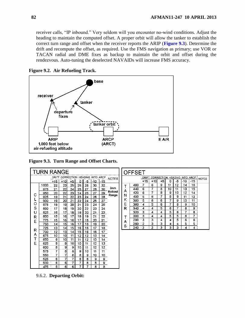
82 AFMAN11-247 10 APRIL 2013
receiver calls, “IP inbound.” Very seldom will you encounter no-wind conditions. Adjust the
heading to maintain the computed offset. A proper orbit will allow the tanker to establish the
correct turn range and offset when the receiver reports the ARIP (Figure 9.3). Determine the
drift and recompute the offset, as required. Use the FMS navigation as primary; use VOR or
TACAN radial and DME fixes as backup to maintain the orbit and offset during the
rendezvous. Auto-tuning the deselected NAVAIDs will increase FMS accuracy.
Figure 9.2. Air Refueling Track.
Figure 9.3. Turn Range and Offset Charts.
9.6.2. Departing Orbit:

AFMAN11-247 10 APRIL 2013 83
9.6.2.1. The tanker pilot will maintain the air refueling altitude throughout the pattern.
The receiver will be established 1,000 feet below the air refueling altitude prior to the
ARIP.
9.6.2.2. When the receiver calls the ARIP, the tanker pilot will depart the orbit at 250
KIAS and proceed toward the receiver while maintaining the predetermined offset. The
tanker pilot will calculate the offset and turn range, using information found in Figure
9.3. The tanker pilot will maintain the offset when proceeding toward the receiver,
ensuring the tanker is properly positioned to make the rendezvous turn. The tanker pilot
will use the A/A TACAN and TCAS to monitor the position of the receiver and
determine when the tanker is at the proper range to initiate the rendezvous turn. When
properly executed, this turn will place the tanker 1 to 3 nm in front of the receiver
heading toward the ARCP on the air refueling track.
9.6.2.3. To assist the receiver in situational awareness, the tanker pilot will call when
halfway through the turn.
9.6.3. Communications:
9.6.3.1. The first radio contact between the tanker and receiver will be not later than 15
minutes prior to the ARCT. Aircrew will make all radio calls as described in AFI 11-2T-
1 Vol 3 and this regulation.
9.6.3.2. The tanker pilot will transmit the following information to the receiver: air
refueling altitude, altimeter, and timing (on time, minutes early, or minutes late).
9.6.3.3. The receiver pilot will transmit the following information to the tanker: ETA to
ARIP (on time, minutes early, minutes late), TAS during rendezvous, altitude, and
altimeter setting.
9.6.3.4. The tanker pilot will normally arrange for three consecutive altitudes for the
rendezvous and air refueling track. The tanker is also responsible for all ATC
communications, navigation, and weather avoidance during air refueling.
9.6.3.5. The receiver pilot will obtain ATC clearance onto the air refueling track and
request clearance to the air refueling frequency, if applicable. Once cleared, the receiver
will monitor the air refueling frequency and may monitor the ATC frequency at their
discretion to increase situational awareness. The receiver PM and jumpseat pilot may
monitor VHF or ATC at the discretion of the aircraft commander.
9.7. Receiver Procedures:
9.7.1. Navigation. The receiver will navigate and track the tanker simultaneously. Use the
FMS for primary navigation, A/A TACAN on the EHSI to track the tanker’s position, and
multifunction display to monitor weather radar.
9.7.2. Prior to ARIP. Crewmembers must ensure a rendezvous with the wrong aircraft is
not attempted. Comparing the A/A TACAN bearing and distance with the TCAS is an
effective method of establishing positive identification. If TCAS is not operational, the tanker
pilot will direct the receiver to cycle A/A TACAN off and then on to make positive
identification.
9.7.3. Fifteen Minutes Prior to ARCT:
84 AFMAN11-247 10 APRIL 2013
9.7.3.1. The receiver pilot will ensure the Receiver Rendezvous Checklist is completed.
The receiver pilot will control and adjust the ARIP arrival time (recommended ETA at
the ARIP is ± 30 seconds) in order to proceed down track at 285 KIAS and arrive at the
ARCP at the ARCT. It is very important to continually verify receiver’s position and the
tanker’s location. The receiver will be established at 1,000 feet below the tanker’s
altitude prior to the ARIP and adjust airspeed to 285 KIAS.
9.7.3.2. Although the turn range is the tanker’s responsibility, the receiver should
monitor the tanker’s position and range. For primary tracking of the tanker, the receiver
will use the A/A TACAN and TCAS as a backup. The receiver pilot will cross-check
navigation and tracking at the tanker’s “10 miles to the turn,” “in the turn,” and “halfway
through the turn” calls to determine if the tanker is positioned properly for the
rendezvous.
9.7.3.3. The receiver pilot will monitor closure on the tanker during the turn. The
receiver should be approximately one-third of the turn range from the tanker when the
tanker is halfway through the turn. The receiver crew will begin scanning the 10- to 11-
o’clock position for the tanker in the turn and evaluate their position relative to the
tanker. As the tanker rolls out, the receiver pilot will align 1 to 3 nm in trail at 285 KIAS.
This is the appropriate place to prepare for air refueling by completing the preparation-
for-contact checklist.
9.8. Rendezvous:
9.8.1. ARIP. The receiver will call the tanker and report crossing the ARIP and current
altitude.
9.8.2. Radio Calls. The tanker will call the receiver, “Panther 11, in the turn,” and “Panther
11, halfway through the turn” (Figure 9.4). At 1 mile the receiver will call “Panther 12,
visual.” The tanker will clear the receiver to the precontact position. The receiver will report
“Panther 12, stabilized precontact.” The tanker will clear the receiver to the contact position,
“Call sign, cleared to contact.” The receiver will report, “Panther 12, contact” when in
position, and the tanker will acknowledge.
9.8.3. Rendezvous Procedures: A/A TACAN is the primary method of determining turn
range during AR missions. Aircrews should back up the FMS while on the refueling track,
using appropriate NAVAIDS. Maintain altitude separation until 1NM on A/A TACAN and
visual contact is established. Once at 1 mile and cleared to precontact position, crews will
consider themselves a formation until separated. If the receiver does not have the tanker in
sight at 1 NM, the receiver will slow to 250 KIAS.

AFMAN11-247 10 APRIL 2013 85
Figure 9.4. Air Refueling Rendezvous.
9.8.4. Alternate Rendezvous Procedures.
9.8.4.1. Primary - Use the computed backup timing.
9.8.4.2. Secondary – Receiver calls miles from the ARCP (off FMS) every 2 NM.
9.8.4.3. Tertiary – Receiver calls DME off of the NAVAID defining the ARIP/ARCP
line every 2 NM (if applicable).
9.9. Closure Procedures:
9.9.1. The initial part of this phase of the rendezvous will generally be performed
electronically. As the receiver, you must constantly monitor your position relative to the
tanker on the A/A TACAN as you begin a closure to 1 to 3 nm (Figure 9.5). The A/A
TACAN bearing indication will continue to move toward the nose as the tanker turns and
approaches your 12-o’clock position. Your approach should be adjusted to arrive 1 to 3 nm in
trail while maintaining 285 KIAS. Plan to continue and arrive at 1 nm with an airspeed of
285 KIAS.

86 AFMAN11-247 10 APRIL 2013
Figure 9.5. Closure.
9.9.2. At 1 nm you must have the tanker in sight and be cleared by the tanker to begin
climbing to air refueling altitude and closing to the precontact position. Remember that you
are 35 knots faster than the tanker, so decrease airspeed incrementally as you approach the
precontact position. At 1/2 nm you should be at 275 KIAS and slowing to 250 KIAS when
arriving at the precontact position. The approach to the tanker is on a 10-degree climb line.
Maintain the tanker in the center of the windscreen and have the copilot advise you of
airspeed changes or deviations. The closer you get to the precontact position, the more you
will need to minimize bank and heading changes. The tanker will move toward the upper
center of the windscreen as you approach the precontact position.
9.9.3. To get a good visual picture, position your seat so your sight picture does not change
each time you fly a rendezvous. Use the tanker as your attitude indicator, but resist the
temptation to fixate. As you get closer, make smaller and smaller corrections as though you
were flying an ILS on the tanker. Remember, the tanker continues to get bigger in the
windscreen as the range decreases.
9.9.4. The three main factors you will be controlling throughout this phase are the azimuth,
elevation, and rate of closure.
9.10. Overrun Procedures:
9.10.1. An overrun is indicated any time the receiver appears to be moving ahead of the
tanker during the rendezvous. An overrun can be detected by electronic or visual means in
either aircraft. As a technique, if the receiver is less than 1/3 of the computed turn range
(half-way through the turn) or the bearing pointer is below the 45 degree index, an overrun
can be expected. For example, if the tanker is halfway through the turn with a computed turn
range of 15 miles, and the receiver’s A/A TACAN shows a range of 2.3 nm or the tanker is
visually at the receiver’s 9 o’clock position, an overrun is in the making.
9.10.2. The first crew to recognize an overrun will make an advisory call, “Panther, initiate
overrun procedures.” The tanker will accelerate to 285 KIAS and maintain the air refueling
altitude while rolling out on track. After overtaking the receiver, the tanker will slow to 250
KIAS. The receiver will slow to a minimum of 250 KIAS, maintain 1,000 feet below the air
refueling altitude, and maintain track. An “S” turn maneuver may be used (if necessary) to

AFMAN11-247 10 APRIL 2013 87
help the receiver drop back and, if overtaken by the tanker, to establish an adequate
separation.
9.10.3. Once the tanker is in front of the receiver and there is a 1,000-foot altitude
separation, either aircraft may call, “Panther, terminate overrun.” Both aircraft may then
reestablish their rendezvous airspeeds. When the receiver acquires the tanker visually and
calls, “Panther 12, visual,” the tanker may then clear the receiver to the precontact position.
Normally the receiver should terminate the overrun procedure.
9.11. Precontact Position:
9.11.1. The precontact position is 50 feet directly behind the tanker and 15 feet below
(Figure 9.6). When stabilized in this position, the receiver has 9 feet of tail-to-belly
clearance on the tanker, which should place the tanker’s wingtips just filling your side of the
windscreen.
Figure 9.6. Precontact Position.
9.11.2. The aircraft commander may point out other visual references, such as the following
aircraft components: engine nacelles, trailing edge of wings, antennae, and AOA vanes.
9.12. Maneuvering Requirements for the Tanker:
9.12.1. The tanker may have specific maneuvering requirements after the receiver calls in
the precontact position. The tanker must have stabilized the refueling airspeed, altitude,
course, and heading. At this point in the air refueling pattern, the tanker must think in terms
of helping the receiver wherever possible. Using careful corrections enables the receiver to
fly a much smoother pattern. The tanker will not exceed 30-degree AOB in precontact and
contact positions.
9.12.2. The tanker will use the autopilot as the primary means of establishing a smooth
platform. The tanker will control airspeed deviations by making small throttle movements.
Throughout this portion of the pattern, the tanker will not make large corrections (that is,
more than 10 knots or 200 feet) without notifying the receiver.
9.12.3. The autopilot will be used to achieve the most stable tanker platform. The autopilot is
capable of making small corrections far more efficiently than a pilot, but the pilot must be
prepared to call for breakaway at the first indication of a malfunction. If it becomes necessary

88 AFMAN11-247 10 APRIL 2013
to change the autopilot configuration, direct the receiver to return to the precontact position.
Even though the aircraft is on autopilot, keep one hand on the control column and one hand
immediately available for throttle use. Do not engage or disengage the system while the
receiver is in the contact position.
9.12.4. The tanker must make smooth control inputs, especially during contact position
maneuvering. Avoid abrupt or large inputs to pitch attitude, power, and bank angle—smooth
movement is the key.
9.12.5. Some specific techniques for power and airspeed adjustment are useful for smooth
tanker flying. The tanker will establish and stabilize the airspeed before the receiver moves to
the precontact position so you can then leave the throttles alone, for the most part, throughout
contact maneuvering. Your need to make changes should be infrequent. As the air refueling
maneuvers continue, the aircraft becomes lighter and requires less power.
9.12.6. Probably the most significant hazard to smooth tanker flying is turbulence. Because
turbulence is almost always going to be present, learn to deal with its effects. Remember, the
turbulence level cannot exceed moderate up to the precontact position or light for the
precontact or contact position. The best way to fly with turbulence is to ignore small pitch-
and-roll changes and make a correction when the attitude does not return to its original
position.
9.12.7. The aerodynamic effects of a T-1A receiver on the tanker are negligible compared to
the effects of a large receiver.
9.13. Receiver Procedures for Maneuvering From Precontact to Contact:
9.13.1. Begin this maneuver by stabilizing in the precontact position with a zero rate of
closure and wait for clearance from the tanker to proceed. Trim the aircraft for hands-off
flight and note the position of the throttles. Also, position your arm to allow for small and
positive movements while staying comfortable throughout the maneuver. Spending extra
time to stabilize the aircraft in the precontact position allows for a smoother transition to
contact and a more stable contact position.
9.13.2. After receiving clearance to the contact position from the tanker, approach the
contact position slowly, using only 2 to 3 knots of closure or approximately 1 foot per
second. Fly this maneuver by making small movements and small power changes. Always
pause to evaluate the effects of each input and be prepared to take some input back out. For
example, a small movement of the throttles to increase closure may require an even smaller
reduction in power once that increase takes effect.
9.13.3. Flying this maneuver will require almost constant small inputs or adjustments,
especially as you arrive at the contact position (Figure 9.7). Continue making the necessary
adjustments and then stabilize in the contact position. The instructor will point out the
references for the contact position. Distinct references include: 1) placing the bottom of the
VHF antenna on the stripe painted on the bottom of the aircraft, and 2) being able to see the
AOA vanes in front of the leading edge of the wing.

AFMAN11-247 10 APRIL 2013 89
Figure 9.7. Contact Position.
9.13.4. In addition to the possibility of some light turbulence, be prepared to overcome the
effects of jetwash, wingtip vortices, and wake turbulence. These effects are generated by the
tanker aircraft and, unlike turbulence, are usually in the same location. Use power cautiously
to avoid driving your aircraft into the tanker’s jetwash or increasing closure to the point
where a breakaway must be declared. Remember, you will need to reduce power when
closure begins and then make another power adjustment to counter that reduction.
9.14. Maintaining Contact Position:
9.14.1. The most important point to remember when flying in the contact position is to
always make small corrections. Your corrections should be limited to approximately a 2-
degree bank change and a 1-degree pitch change. Give all corrections time to take effect and
be prepared to remove some of the correction as it takes effect. If large corrections are
required, closure is too fast, or you are uncomfortable with the approach, return to the
precontact position and stabilize.
9.14.2. The contact position is one specific point in the sky in relation to the tanker aircraft.
That point does not move, regardless of the conditions, but your aircraft will move almost
constantly. The contact point rests within an envelope behind the tanker (Figure 9.8). The
envelope’s vertical limits are ± 10 degrees, its fore and aft limits are ± 6 feet, and its lateral
limits are ± 10 degrees. Work to stay at the center of that envelope, keeping corrections as
small and smooth as possible. You will actually be flying around and through that point,
attempting to stay as close to it as possible. Constantly be aware of your roll tendency,
attitude, and power settings.

90 AFMAN11-247 10 APRIL 2013
Figure 9.8. Contact Envelope.
9.14.3. The tanker will normally use 15 degrees AOB in turns while the receiver is in the
contact position. However, the tanker may use 30 degrees AOB for maneuvering after the
receiver has attained proficiency at 15 degrees AOB. The receiver must anticipate the power
and yoke inputs required to maintain the proper position.
9.15. Breakaway Maneuver:
9.15.1. A breakaway maneuver will be accomplished during precontact or contact
maneuvering any time the tanker or receiver determines aircraft separation is required
immediately to avoid a collision or prevent a dangerous situation from developing. The
tanker’s call sign will be used to initiate the breakaway. The radio call will be, “Panther 11,
breakaway, breakaway, breakaway,” and it may be called by either aircraft.
9.15.2. Once the call is initiated, the tanker will advance throttles to approximately MCT and
maintain the current bank angle. The receiver will retard the throttles to idle and call for
speed brakes (as required by the severity of the closure) while backing and descending. The
receiver will report when “well clear.” If the tanker is not in sight, the receiver will continue
descending to the bottom of the altitude block and attempt to locate the tanker visually and
by electronic means. The tanker will continue to accelerate until the receiver calls, “well
clear.” The tanker terminates the breakaway when the receiver reports “well clear.”
9.15.3. Breakaway procedures are practiced to prepare for actual situations that may be
encountered. Either aircraft may direct the practice breakaway. Before the practice
breakaway is initiated, a preparatory radio call will be made by saying, “Panther 11, practice
emergency separation ____ seconds after contact call.” Then the breakaway procedures in
paragraphs 9.15.1 and 9.15.2 will be complied with. After the procedure has been executed,
the tanker will direct the next maneuver to be completed (separation for another rendezvous,
move to precontact position, etc.).

AFMAN11-247 10 APRIL 2013 91
9.16. End Air Refueling (E A/R) Point. Prior to the exit or E A/R point, the tanker should
coordinate for further clearance for the tanker and receiver. The final communications to be
performed in the air refueling track is at the E A/R point and is given by the tanker to the
receiver. The tanker will pass the ARTCC frequency, Mode 3 setting, and any clearance
instructions received.
9.16.1. Separation. Prior to the E A/R point, the tanker will climb to the top of the altitude
block while the receiver descends to the bottom. Both aircraft will report when established at
the separation altitude on air refueling primary and then contact ARTCC for clearances and
termination of MARSA. NOTE: The tanker may have the receiver return to the visual
formation position if a formation recovery is desired.
9.16.2. Post-Air Refueling. Each aircraft will complete the applicable post-air refueling
checklist. The tanker will call the ARTCC when aircraft are vertically separated, and the
receiver will report to the ARTCC with altitude. Both aircraft will continue under separate
IFR clearances.

92 AFMAN11-247 10 APRIL 2013
Chapter 10
LOW-LEVEL NAVIGATION AND FORMATION AIRDROP
Section 10A—Overview
10.1. Mission Objective. The main objective of an airdrop mission is to deliver cargo and
troops to the drop zone (DZ) safely, accurately, and on time.
10.2. Formation Considerations:
10.2.1. During airdrop familiarization training, you will be required to fly formation while
performing numerous other tasks at low level. Situational awareness is essential for this
phase of training.
10.2.2. Lead’s primary responsibilities are to navigate, time, clear for the formation, and
provide effective formation communications.
10.2.3. The wingman’s responsibilities include maintaining formation position by visual
reference and A/A TACAN, clearing through lead, backing up lead in navigation, and being
prepared to assume the lead position and responsibilities at any time.
Section 10B—Low-Level Navigation on a Military Training Route (MTR)
10.3. Purpose. The purpose of low-level navigation is to fly a selected ground track to arrive at
a designated DZ at a designated time over target (TOT). Low-level flying requires extensive
preflight planning to ensure flight safety and maximum training from each sortie. Use these skills
and techniques to fly the airdrop missions.
10.4. Preflight Coordination. The first step in preparing for a low-level mission is to be
completely familiar with the route requirements and the following applicable publications: FLIP
(AP/l and AP/1B), and ensure that all CHUM is current. Check with the controlling agency for
unpublished restrictions and the low-altitude charts for airspace restrictions.
10.5. Mission Planning:
10.5.1. T-1A low-level missions are normally flown at 240 knots groundspeed (4 nm per
minute) on IFR and VFR military training routes (IR and VR), and 210 knots groundspeed
(3.5 nm per minute) on slow-speed low-altitude training routes (SR). Ensure the planned
speed is approved for the selected route. Some routes have speed restrictions the T-1A cannot
comply with. Use the performance charts in TO 1T-1A-1-1 to determine a fuel flow for the
airspeed you are flying. Check the route length and determine your capability to complete the
route with the fuel on board.
10.5.2. When preparing for the flight briefing, check the forecast weather for the route to
include wind and flight hazards and confirm final coordination for the route. Compute an
IAS that will give the preplanned groundspeeds based on current conditions. See AFI 11-202,
Volume 3; AFI 11-2T-1, Volume 3; and applicable MAJCOM publications for minimum
ceiling and visibility for low-level training.

AFMAN11-247 10 APRIL 2013 93
10.5.3. Plan an altitude that gives adequate terrain and obstacle clearances. Low-level routes
are flown between 500 and 1,500 feet AGL, depending on pilot experience and comfort
level. Refer to AFI 112T1, Volume 3, for various restrictions on low levels.
10.6. Route Development:
10.6.1. The tactical pilotage chart (TPC), a 1:500,000-scale chart, is the best choice to use
while flying low-level navigation in the T-1A. The joint operational graphic (JOG) chart, a
1:250,000 scale chart, is useful for detailed route study and planning (especially on the IP to
DZ run-in), but it can be unwieldy to use on the flight deck and requires excessive map-
reading. Essential information for accomplishing a successful mission is on or can be added
to a TPC.
10.6.2. The first step in planning the route is to draw the route corridor and update the chart
with the latest information from the Chart Update Manual (CHUM). Identify significant
obstacles and high terrain within that corridor. Annotate low-level charts with the location
and dimensions of Class A, B, C, and D airspace; civil and military airfields; potential high
density traffic areas (parachute activity areas and ultra light, hang glider sites, etc.); and noise
or sensitive environmental areas that should be avoided within 5 nm of any planned VFR
route or MTR lateral boundary. Annotate and brief applicable airfield approach control
frequencies in the vicinity of Class A, B, C, and D airspace. In addition, annotate and brief
the intersection of other VFR MTR (VR) or IFR MTR (IR), if applicable, and any other
possible areas of conflict. WARNING: This part of the planning is imperative for flight
safety; do not neglect it.
10.6.3. Select a DZ along your route and an easily identifiable initial point (IP) located about
3 to 4 minutes prior to the DZ to allow sufficient routing for ingress to and egress from the
DZ. The IP is an easily discernible point, located along the route of flight prior to the DZ,
used to establish a final heading and adjust timing to make the DZ at the TOT.
10.6.4. The IP plays an even more important role in flying airdrop missions later in training.
For now, select a distinctive timing start point inside the route corridor, but not necessarily at
the published entry point. Construct the desired ground track from the start point to the IP,
using easily identifiable turn points so the ground track remains within the corridor. Be sure
to consider aircraft turn performance and route corridor when selecting turn points. NOTE:
The coordinates in FLIP AP/1B are for the route center line, but you do not necessarily have
to locate your turn points on that center line.
10.6.5. The best features to use as check and turn points are normally natural features (as
opposed to manufactured features which may change shape or be camouflaged). Always try
to choose route check points close to the track. Turn points should be chosen by keeping
uniqueness, vertical development, funneling features, and terrain or obstacle clearance
requirements in mind. Avoid using a turn point that cannot be seen until the last minute.
10.6.6. It is important to try to read the shape of the land from the map. Pay particular
attention to turn points so you can visualize the terrain and the features you are going to see
as you approach the turn points. Look for funnel features (for example, converging roads,
railroads) or other prominent pre-turn check points.

94 AFMAN11-247 10 APRIL 2013
10.6.7. Do not try to memorize the route, but study it very carefully after it has been
developed. The more familiar you are with the check points and turn points, the easier they
will be to identify while flying the route.
10.7. Map-Marking. In addition to the information in AETC/TRSS Handout 11-1, annotate
your map as follows:
10.7.1. Circle turn points, but do not obliterate or obscure them. Draw the MTR corridor
from the entry point to the planned exit point.
10.7.2. Plan and measure the turning radius for the groundspeed and bank angle used. Refer
to Chapter 20 of AFMAN 11-217, Volume 1, for aircraft turning performance.
10.7.3. Mark the entire route with 1-minute tic marks, taking into account the slowdown for
DZs.
10.7.4. Compute continuation fuels for points along the route. Continuation fuel is the
minimum required fuel to complete the route at the planned speeds and altitudes plus fuel to
return to base with AFI 11-202, Volume 3, fuel reserves.
10.7.5. Calculate a bingo fuel (including the required minimum AFI 11-202, Volume 3, fuel
reserves) for return to base or destination airfield by the most practical means from the most
distant point on the route.
10.7.6. Draw information boxes aligned with each leg. Enter heading, airspeed, continuation
fuel, and other relevant information.
10.7.7. Annotate information and emergency and alternate airfield locations you feel are
necessary to expedite your divert, if required.
10.7.8. Plan for your routing to and from the low-level route. Study features along the route
to the entry point.
10.7.9. Compute an ERAA for the planned portion of the low-level route and clearly
annotate it for easy in-flight reference. Compute this altitude to provide 1,000 feet (2,000 feet
“mountainous” [FLIP]) clearance above the highest obstacle within 25 nm either side of the
AP1B route center line.
10.8. In-Flight Preparation:
10.8.1. Maintaining an accurate altimeter setting is very important when flying low level
because it helps determine your height above the terrain. When the weather is changing
rapidly, the altimeter setting is probably changing rather quickly as well. Always try to obtain
a current altimeter setting within 1 hour of entering the route. An altimeter setting is available
from the PMSV, FSS, ARTCC, or a metro forecast. (Depending on the preflight itinerary and
route of flight, the metro forecast may be the least timely.)
10.8.2. Certain preparations and precautions should be taken before entering a low-level
route to avoid encountering any surprises or diversions:
10.8.2.1. Carefully review the low-level entry by checking the first leg’s heading,
altitude, and prominent features near the entry point. Prepare and review an abort plan
should the need arise to leave the route.

AFMAN11-247 10 APRIL 2013 95
10.8.2.2. Review the planned terrain clearance altitude you will fly and set the radio
altimeter warning to that altitude (500 to 1,500 feet). Set the DH on your EADI to an
altitude 10 percent below the planned terrain clearance altitude (for example, 10 percent
of 500 feet, or 450 feet on the DH) so you will have an additional “warning” signal if you
descend below the planned altitude.
10.8.2.3. Compare the actual fuel available against the planned fuel to ensure adequate
fuel exists to complete the mission. Resolve any differences and ensure the fuel is
balanced between the wing tanks.
10.8.2.4. Secure any loose items in the cabin and fasten your seat belts and shoulder
harnesses. Request a descent clearance far enough before the entry point to allow the
ARTCC to respond and for you to descend to the entry altitude. Other radio calls will be
required and will vary depending on the type of route being flown.
10.8.2.5. Complete the low-level entry and exit checklists. The crew briefing should
cover how you will enter the route. For altimeters, ensure proper setting prior to entering
the route. Radio altimeters should be set as described in paragraph 10.8.2.2. Set the
ERAA in the altimeter altitude preselect window. Post an MCT for route abort
procedures. Ensure belts and harnesses are fastened and loose items are secured prior to
entering the route.
10.8.3. Entry into an IFR MTR requires a clearance from the ARTCC, approach control, or
other controlling agency specified in FLIP AP/1B. The ARTCC will assign a frequency to
monitor or assign the one published in the AP/1B. Position reports to the controlling agency
at specified points are required on some routes. These points will be listed in AP/1B and
should be marked on your map.
10.8.4. When flying a VFR MTR or an SR, you are not required to obtain entry clearance.
Cancel the IFR flight plan and monitor FSS on 255.4 megahertz (MHz). When entering a
VFR MTR, make a radio call to advise FSS and other aircraft of your callsign, groundspeed,
en route altitude, entry time, and exit time.
10.8.5. Be prepared to make a pilot report (PIREP) if any significant weather is encountered
or if weather is different from what was briefed.
10.8.6. When entering an IFR MTR, set the IFF as specified by the controlling agency.
Squawk “4000” when on a VFR MTR and “1200” when on an SR.
10.8.7. Remember to start the timing clock over the timing start point. This is the only way
you can begin the DR process.
10.8.8. Although lost communication procedures may vary depending on the individual
situation, the following simple solution applies to IFR MTR, VFR MTR, or SR: remain
VMC and land as soon as practical.
10.9. Descent and Leveloff Procedures:
10.9.1. For descent into a low level, cross-check the radio and pressure altimeters at an
altitude between 1,000 and 2,000 feet AGL.

96 AFMAN11-247 10 APRIL 2013
10.9.2. Once the cross-check of altimeters is complete, begin a descent to the final low-level
altitude. Before making this descent, calculate a leveloff altitude (MSL) to provide desired
terrain clearance (AGL).
10.9.3. On VFR MTR and SR, attempt to cross the entry point at the final low-level altitude,
but comply with route restrictions that specify a higher altitude clearance than originally
intended.
10.9.4. While flying the low level, observe the restrictions, requirements, and hazards
pertinent to this type of operation. Evaluate weather conditions to ensure the ceiling remains
in accordance with applicable directives. Continually check the map for hazards and
obstructions near the course.
10.10. Orbit Procedures. In the event the weather prevents a VMC formation flight to the low-
level entry point, the following procedure may be used to rejoin a formation prior to route entry:
10.10.1. The flight lead will prebrief the orbit point, holding turn direction and expected
altitude for rejoin. The lead aircraft should plan to take off, as a minimum, 8 minutes earlier
than normally required to enter the route. This allows two standard holding patterns to
complete the rejoin prior to route entry time. The suggested minimum takeoff interval is 4
minutes. The lead aircraft will hold at an orbit point no lower than 1,500 feet AGL. The
wingman will enter the same holding pattern a minimum of 1,000 feet above the lead’s
altitude until both aircraft are in VMC, a visual tally is confirmed by the wingman, and the
flight lead declares MARSA. NOTE: MARSA requires a letter of agreement with the owning
ARTCC facility.
10.10.2. The wingman will maneuver as required to complete the rejoin. If a rejoin cannot be
accomplished, the wingman will coordinate to obtain clearance to depart the orbit first.
10.10.3. Following the low-level portion of the flight, lead may be required to separate the
formation due to weather prior to RTB. This may be accomplished by holding in VMC while
coordinating for separate clearances or, if weather allows, coordinating en route.
10.11. Fuel Considerations:
10.11.1. Fuel management is critical during most flight activities, but it becomes even more
critical during low-level flight because so many other factors demand your attention over an
extended period of time.
10.11.2. To help eliminate the problem of low fuel during low-level flight, thoroughly plan
for contingencies, such as altering the flightpath to avoid weather and airspace or route
restrictions. Any change in the flight plan or in-flight delays may cause unexpected fuel use.
10.11.3. Other unplanned events, such as aircraft malfunctions and bird strikes, may cause
an abort of the low-level part of the mission and a change of destination, making it important
to be continually aware of how much fuel remains.
10.11.4. Proper fuel management begins with an accurate fuel log. Fuel entries need to be
computed very accurately from the TO 1T-1A-1-1 fuel charts. A very good technique is to
compare actual fuel used against the planned amount, continuation fuel, and bingo fuel at
every second or third checkpoint between entry and exit. If the fuel remaining is greater than
or equal to the continuation fuel, continue the route and land with the planned reserve. If it is
less, plan to abort the route and proceed to the base of intended landing.

AFMAN11-247 10 APRIL 2013 97
10.11.5. Bingo fuel is calculated from the most distant checkpoint from the landing field. If
you have not reached this point and are at bingo fuel, abort the route and proceed to an
alternate landing field. By planning properly and checking the fuel at all checkpoints, you
should never be down to bingo.
10.11.6. If the low level is aborted, attempt to call the controlling agency in the same way
normal low-level exit calls are made. Because the situation is unplanned, give the location,
altitude, description of the situation, and plan of action. Remain VMC until the controlling
agency gives a clearance. If contact cannot be established, return to the base VFR while
remaining VMC.
10.12. Flying the Route:
10.12.1. A considerable amount of time has been spent planning this sortie, so don’t throw it
all away as soon as you get airborne. Fly the plan. If all you do is fly an accurate heading and
airspeed and turn on time, you will not be very far off by the end of the sortie.
10.12.2. Without jeopardizing clearing en route to the entry point, fly the planned headings,
speeds, and leg times from takeoff to the entry point. You may use NAVAIDs such as
TACAN to confirm your position if necessary, but try to maintain position awareness by
using the clock, the map, and ground features until you visually acquire the entry point.
10.12.3. Clearance onto a low-level route must be issued by the proper controlling agency,
normally the ARTCC or as specified in AP/1B. When flying low-level routes, maintain radio
contact with traffic control and service agencies. Do not hesitate to have the jumpseat
monitor frequencies to help minimize the PF and PM workload. The ARTCC controls access
into and out of IFR MTR, as well as airspace going to and from low-level routes.
10.12.4. Although the FSS provides advisories and coordination services, it does not control
any airspace or routes. The FSS monitors VFR MTR activity, broadcasts severe weather
advisories, may provide notification of route closure, and may act as a radio relay to ARTCC.
10.12.5. When entering an IFR MTR, you are still on an IFR clearance and following an IFR
flight plan. Enter at the IFR altitude specified in the FLIP AP/1B route description. When
entering a VFR MTR or an SR low-level route, cancel the IFR clearance and proceed VFR to
the entry. Before entry, observe hemispheric altitude rules above 3,000 feet AGL. When not
prevented by other route restrictions, enter a VFR MTR or SR at the altitude specified during
the briefing and commensurate with your experience (1,500 feet AGL to a minimum 500 feet
AGL).
10.12.6. Before arriving at the entry point, make sure the heading system is accurate.
Identify the entry point as early as possible and position the aircraft to line up on the heading
and on track before overflying it. Enter and exit MTRs only at the designated points
identified in the FLIP AP/1B as entry, alternate entry, exit, and alternate exit points. This
restriction provides an orderly flow of traffic in and out of the route and some assurance of
adequate separation of multiple aircraft using the route. The Federal Aviation Administration
(FAA) has evaluated and approved these points; they do not conflict with other airspace.
Hack clocks passing the timing start point. Once inside the route structure, adjust the speed
for the first leg. Adjust the IAS for temperature, altitude, and wind to ensure accurate timing
on each leg.

98 AFMAN11-247 10 APRIL 2013
10.12.7. When you are flying along a planned route, the best method of map-reading is clock
to map to ground. Always fly with a definite plan in mind. Excessive map-reading can lead to
less accurate flying. Ensure the aircraft is trimmed up in all three axes with power set to
maintain the desired airspeed. This ensures control of the aircraft is accomplished and
composite flight becomes easier.
10.12.8. As PF, keep your focus out of the flight deck as much as possible and look for
ground references and possible conflicts (for example, an unexpected aircraft in your area or
a large bird). Clearing continuously is essential at low level. Following the principles of good
crew coordination, have the PM and/or jumpseat serve as map reader and navigator. They
should keep you informed on what to expect as far ahead on the route as you feel
comfortable handling the aircraft. Ensure all crewmembers help clear.
10.12.9. If off track, make heading corrections as necessary to get back on track, but avoid
making excessive ones. Remember, simply flying accurate heading and airspeed and turning
on time, will keep the aircraft close to course at any time throughout the route. Use the
features on the track as aim points. Look for these points on your chart ahead of your present
position. Then acquire these points visually as soon as possible and confirm their position by
use of the clock and timing marked on the map. Develop a work cycle for such important
items as monitoring actual against continuation fuels, monitoring actual against planned
times at turn points, cross-checking headings after turns, and knowing when the PM and/or
jumpseat should be giving the next checkpoint briefing.
10.12.10. Make every effort to arrive over the DZ at the TOT. Make corrections as early as
possible so large airspeed changes are not required approaching the DZ. It might be
necessary to recompute airspeed based on the distance remaining to the DZ and make the
appropriate correction. Remember, during formation airdrop training, you will also have the
wingman to think about.
10.12.11. While flying the low level, you will be regularly climbing and descending to
maintain the desired altitude. Remember to adjust power before changing altitude and to lead
leveloff by 10 percent of the RA or VSI. If large altitude changes are required, start the climb
further back from the obstruction.
10.12.12. The following three low-level methods—contour, modified contour, and constant
altitude—may be used for airdrop missions as follows:
10.12.12.1. The contour method requires the flight to maintain 500 feet AGL altitude
throughout the route. This method calls for following the terrain exactly, which results in
an extremely rough ride and may require a lot of work on the part of the aircrew to
observe and fly the route safely. As the terrain rises and descends, the aircraft must match
the contour to maintain the constant 500-foot clearance.
10.12.12.2. The modified contour method is the primary method for low-level flying in
the T-1A. This method utilizes a smooth terrain flight profile, rather than an exact
terrain-following flight profile.. If a section of the terrain rises and descends numerous
times, the aircraft must climb to an altitude that allows an average higher than 500 feet
clearance to avoid ever flying lower than 500 feet AGL over that section of the route.
Therefore, the average altitude will end up being higher than 500 feet (maybe 600 to 700

AFMAN11-247 10 APRIL 2013 99
feet) as the terrain continues to rise and drop beneath the aircraft as you make continuous
attempts to fly the contour.
10.12.12.3. The constant altitude method is flown by computing an altitude that allows a
500-foot or higher clearance above the highest obstacle along, and 5 nm on either side of,
the entire route. As the terrain varies, fly a constant altitude regardless of the height
above the ground. Using this method will familiarize the crew with the specifics of a low-
level route because the field of vision is much larger.
10.12.13. Accurate DR and time control to the DZ require knowledge of the groundspeed.
To determine the groundspeed, know the distance between landmarks and accurately
measure the time it takes to cover the distance between them. Annotate the chart with
measured distance and pre-computed times and make the calculations on the spot.
Alternatively, utilize the groundspeed readout on the MFD, when allowed by your syllabus
or training ROE. As soon as the groundspeed is determined, make adjustments to compensate
for the wind.
10.12.14. Although instruments need to be cross-checked regularly, keep your head out of
the flight deck as much as possible while flying low level. At 500 feet AGL, you are only
seconds above the ground and cannot allow your attention to be diverted for even a short
amount of time.
10.12.15. Avoid becoming complacent during the RTB. Give the return leg the same
emphasis you gave the leg-to-route entry.
10.13. Time Management Procedures:
10.13.1. Accurate DR and time control on the low-level route require the timing clock be
started over the timing start point. It is also necessary to compare the actual time of arrival to
the preplanned elapsed time annotated at each turn point. Control the groundspeed with
power adjustments on each leg of the route. The last timing check before the DZ is at the IP.
Controlling groundspeed along the route reduces the need to make large adjustments to arrive
at the DZ at the TOT.
10.13.2. For every second late or early, increase or decrease groundspeed by 1 knot and hold
that change for the number of minutes equal to the nms per minute you are flying. For
example, if you are flying at 240 knots groundspeed (4 nm per minute) and are 10 seconds
late, you should increase the groundspeed by 10 knots and hold the correction for 4 minutes.
If you are flying 210 knots groundspeed (3.5 nm per minute) and are 10 seconds late, you
should increase groundspeed by 10 knots and hold the change for 3.5 minutes.
10.13.3. The time or speed in this relationship may be changed as long as the time-speed
ratio remains constant. For example, in the situation in paragraph 10.13.2, at 240 knots
groundspeed you could have increased groundspeed by 20 knots for 2 minutes or 40 knots
for 1 minute. Use this correction when you need to complete the time-speed correction in a
short amount of time.
10.14. Course Corrections:
10.14.1. If you are off course when flying low level, several aids have been developed to
help you get back on course. The most basic method is to simply aim for a distant feature on

100 AFMAN11-247 10 APRIL 2013
track. Another simple method, if available, is to use linear landmarks such as roads or
drainage patterns to serve as a funnel to steer you back to track.
10.14.2. Many times these aids are not available so other methods to correct back to course
must be employed. The standard closing angle (SCA), based on the 60-to-1 rule used to solve
other navigational problems, is one such method. The SCA is calculated with the following
formula: SCA = 60/groundspeed (nm per minute). Therefore, at 210 knots groundspeed (3.5
nm per minute), SCA = 60/3.5 = 17o and at 240 knots groundspeed (4 nm per minute), SCA
= 60/4 = 15o.
10.14.3. For every mile off track, change the heading toward track by the SCA for 1 minute.
For example, you are flying 240 knots groundspeed and are 2 nm right of track with a
planned magnetic course of 100 degrees. The correction is 15 degrees left to 085 degrees for
2 minutes. The course could also be corrected in one-half the time by doubling the SCA; that
is, 30 degrees left to 070 degrees for 1 minute.
10.15. Reorientation:
10.15.1. At one time or another, all pilots experience moments when they have some doubt
about their position when flying low level. In those situations, always remember to follow
basic DR procedures, rely on them, and above all, do not panic.
10.15.2. Often what you see out the windscreen does not exactly match what is on the map.
Many cultural features are not on the map, and that is why it is important to work from the
map to what is seen on the ground. When a checkpoint time is reached, but the checkpoint
cannot be located, turn on time and try to locate other map features.
10.15.3. If you are still unsure of the position, exercise the three Cs—climb, conserve, and
confess:
10.15.3.1. Climb to increase visual range. Vision to the horizon is about 11 nm on the
ground, 24 nm at 500 AGL, and 42 nm at 1,500 feet AGL. At a higher altitude, visual
range is increased, providing more information and landmarks to confirm a position. If
you are unsure of your position, climb to the ERAA to confirm it.
10.15.3.2. Conserve fuel by slowing and climbing to a more fuel-efficient altitude.
10.15.3.3. Confess disorientation to yourself and others (FSS or ARTCC). Do not be
afraid to ask for help; it’s available.
10.15.4. The navigation map does not contain new features, and the absence of these
features tends to contribute to disorientation. A new manufactured feature might not yet be
on the map, or many times there is not enough map space to include all the actual geographic
features. The opposite can also be true—bridges and towers might be dismantled or
relocated. The fact that many areas contain one or two similarly positioned features also
tends to contribute to the confusion. Positively identify a checkpoint by looking at the
surrounding features and finding something unique about the features in reference to the
checkpoint.
10.16. Turn Point Procedures. When flying low level, your workload will include flying the
aircraft, clearing, looking for checkpoints, maintaining terrain clearance, checking ETAs and fuel
quantities, and continually evaluating new and changing information. Each of these items is
important. One way to ensure that all important items are completed at each turn point is to

AFMAN11-247 10 APRIL 2013 101
develop a good habit pattern. To develop this habit pattern, ensure these items are completed in
the following sequence at each checkpoint:
10.16.1. The PM will announce the next heading, turn direction, and altitude about 1 to 2
minutes from the turn point.
10.16.2. Both the PF and PM will clear during the turn.
10.16.3. The PM will note the time and fuel before or immediately after each turn point and
compare the actual fuel remaining with planned continuation fuel at that point.
10.16.4. The PF will apply the airspeed, altitude, and heading correction as necessary after
rollout on the next leg.
10.16.5. The PM will periodically accomplish the cruise checklist to ensure all systems are
functioning normally. Due to the hazards in the low-level environment, direct reference to
the checklist is not required. A commonly used technique for systems checks during low-
level flight is the acronym “HEFOE,” which stands for: Hydraulic pressure, Engine
instruments, Fuel, Oxygen pressure, and Electrical system. This acronym covers many, but
not all, of the cruise checklist steps.
10.17. Hazards at Low Level:
10.17.1. When flying low level, be alert to obstructions or hazards to low-level flight. Some
are obvious and may at first seem trivial, but the threats are real; and, at low altitude, little
time is available to react to them.
10.17.2. Even though you have “chummed” the chart, there may be new towers that are not
in the CHUM. In areas where there are many towers, it may be difficult to locate all of them
visually.
10.17.3. Steep terrain is a hazard when you fail to calculate a start climb point or wait too
long to start the climb.
10.17.4. Airfields are hazardous because of small, hard-to-see aircraft which may be
operating from the airfields.
10.17.5. Birds can pose a very serious hazard. Check bird activity in accordance with local
directives when planning any low-level flight. Do not consider wildlife areas or known
migration routes as trivial. Until you have seen or experienced a bird strike, you cannot fully
comprehend the damage that can be done when a bird is hit at 200+ knots. Again, the
problem is being able to see the hazard in time to avoid it. Report excessive bird activity in
the blind on 255.4 and also report the conditions to the SOF.
10.17.6. Another hazard is crossing special-use airspace areas that are active by NOTAMs.
Restricted airspace can be particularly hazardous and must be avoided unless clearance to
cross is granted by the appropriate controlling agency.
10.18. Mountainous Terrain:
10.18.1. Be aware that low-lying checkpoints or turn points can be easily hidden if you are
not exactly on track. Adjust the IAS for the altitude flown. Be alert for areas of turbulence on
the downwind side of large features in windy conditions and fly upwind of ridges if possible.

102 AFMAN11-247 10 APRIL 2013
10.18.2. To fly safely over larger contour features, use an early pitch and power adjustment
for a climb to put the aircraft at the desired AGL height as it passes over the highest contour
on heading. When descending on the other side, use an appropriate power reduction to
control airspeed.
10.18.3. Minimum altitude restrictions in appropriate flying publications also apply to
horizontal obstacle clearance when flying in varying terrain. Refer to AFI 11-202, Volume 3;
AFI 11-2T-1, Volume 3; and applicable MAJCOM publications for additional guidance on
flying in mountainous terrain.
10.19. Communication Requirements:
10.19.1. When exiting the low-level route, you transition from the low-level area where
controlling agencies do not have radar and radio contact into controlled airspace where radar
and radio contact are required. Because radio contact may be difficult and numerous
communication requirements exist, this is usually an area of confusion. Therefore, it is
important to establish contact with the controlling agency (usually ARTCC or as specified in
FLIP AP/1B) as soon as possible.
10.19.2. When leaving an IFR MTR, you must contact the controlling agency and receive an
exit clearance. If radio contact cannot be established immediately, climb in VMC and follow
flight plan altitudes and the route while continuing attempts to contact the controlling agency.
If contact is not established after gaining some altitude, climb in VMC and return VFR.
10.19.3. When exiting a VFR MTR or an SR, either stay VMC and return VFR or contact
the controlling agency to resume an IFR flight plan.
10.19.4. If you are unable to contact the controlling agency when leaving a low-level route,
remain VMC, climb to a VFR hemispheric altitude below Class A airspace, and RTB
following the filed flight plan route. Remain below 250 KIAS when you are flying below
10,000 feet AGL.
10.20. Low-Level Emergencies:
10.20.1. Any emergency encountered at low level (to include IMC) will demand a climb to a
safe height above the terrain to safely analyze the situation and ensure radio contact with
appropriate agencies. Be sure to refer to published lost communication and emergency
procedures in FLIP for the route. If you maintain position awareness, you will know where
the nearest suitable airfield or base is anywhere along the route and be able to head toward it
if required.
10.20.2. If IMC cannot be avoided, immediately abort the route and climb to the computed
emergency route abort altitude. The climb should be expeditious, using a precomputed MCT
N1 climb power setting and an airspeed of 250 KIAS (maximum). Immediately establish a
climb on course and do not, under any circumstances, attempt to reenter the low-level route
once an abort has been initiated. Because route aborts can be potentially disorienting, an
immediate transition to instruments is required and close attention to aircraft control and
flight parameters is essential. Continue to climb to the route-abort altitude, level off, squawk
“emergency” (if appropriate), and coordinate with the controlling agency for an IFR
clearance to the destination airfield. CAUTION The ERAA provides 1,000 feet of
clearance (2,000 feet in mountainous terrain) from the highest obstacle within 25 nm either

AFMAN11-247 10 APRIL 2013 103
side of the AP1Broute center line. A climb to a higher altitude may be necessary to ensure
obstruction clearance during the recovery to the destination airfield.
10.20.3. Bird Avoidance/Bird Strike: Any crewmember calls out birds as necessary
(directive then descriptive), do not stall the aircraft or hit the ground (unrecoverable sink
rate) to avoid birds. If a bird is hit, PF initiates a climb to a safe altitude as part of “Maintain
Aircraft Control.” Consider structural damage/controllability checklist, and land at the
nearest suitable airfield.
10.20.4. Engine Failure: PF initiates a climb to ERAA (min) at MCT and 170 KIAS.
10.20.5. Aircraft Malfunctions: PF initiates a climb to leg MSA or top of the MTR corridor
whichever is higher (minor malfunction) or ERAA (major malfunction); use route abort
procedures if needed. Once at a safe altitude, use “normal” EP procedures.
Section 10C—Airdrop Procedures
10.21. Airdrop Considerations. Along with flying formation at low level, it is necessary to
navigate along a specific preplanned route where you will perform one or more airdrops. One of
the most important aspects of the airdrop is timing. Learning to make that TOT is crucial.
Arriving at the TOT depends on good navigation planning, coordination between aircraft, and
precise low-level execution.
10.22. Cockpit/Crew Resource Management (CRM). In an airdrop formation, the need for
CRM becomes very important for completion of the mission. Each crewmember must be fully
aware of the duties required for their position.
10.23. Parameters. Formation airdrop in the T-1A is a day-only maneuver. The planned drop
altitude will normally be 1,000 feet AGL (or 500 feet above the planned route altitude) at 140
KIAS with a 10-degree flap setting. The airdrop altitude and airspeed may be different if
prebriefed prior to accomplishment. Times pertaining to low-level operations (including TOT)
will be computed during mission planning. While flying the low-level route and after passing the
IP, complete the slowdown maneuver and visually acquire the DZ as soon as possible. Maneuver
the aircraft to attain proper alignment with the DZ center line.
10.24. Mission Plan. Use the low-level and airdrop briefing guides in AFI 11-2T-1, Volume 3,
or locally produced IFG briefing guides to brief each mission. The flight lead is responsible for
conducting this briefing.
10.25. En Route Navigation. The flight will perform en route navigation by flying a
preplanned low-level route to the DZ. The wingman will execute all heading changes over the
same geographic points as the lead, while maintaining position on the lead and following the
same geographic path.
10.26. Altitude. The route will be planned at an altitude no lower than 500 feet AGL or as
specified by the AP/1B route restrictions, whichever is higher. Altitude changes, when required,
should be made at specific geographic points. At all times, both aircraft will constantly monitor
the radio altimeter to ensure a flight no lower than 500 feet AGL or as specified.
10.27. Airspeed:

104 AFMAN11-247 10 APRIL 2013
10.27.1. Airspeed for the route will be prebriefed to minimize en route communications, but
may not be constant for the entire route to allow lead the flexibility to adjust speed as
necessary to make the TOT.
10.27.2. Airspeed changes do not have to be announced over the radio, except for slowdown.
As a technique, however, lead may want to call airspeed changes in 10-knot increments over
interplane frequency; for example, “Panther 51, new airspeed 230.” The wingman should
monitor lead’s position visually as well as electronically and anticipate airspeed changes to
make the TOT.
Section 10D—Lead Airdrop
10.28. Route. The route should be planned with an IP that will allow the flight to be on course
inbound to the DZ with minimum maneuvering. After passing the IP, which is located
approximately 3 to 4 minutes from the DZ, lead will initiate a climbing slowdown approximately
3 to 7 nm prior to the DZ.
10.29. Slowdown. The execution of the slowdown will be completed at a predetermined
geographical point or an en route time and will begin with the 500 feet climb from the en route
altitude to the airdrop altitude (Figure 10.1). When lead calls for the slowdown, both aircraft will
simultaneously set power to idle, raise the nose to 10 degrees nose high, set flaps to 10 degrees
(passing 200 KIAS), and adjust the power as required to maintain the airdrop altitude at 140
KIAS.
Figure 10.1. Slowdown.
10.30. DZ Acquisition:
10.30.1. The flight lead has primary responsibility for acquiring the DZ. As part of the
mission planning, the DZ size and elevation should be determined.
10.30.2. Once you pass the IP and initiate a slowdown, be prepared to visually locate the DZ
and maneuver the aircraft to maintain the run-in heading to the DZ. Also be prepared to
adjust for drift to maintain a proper ground track to the DZ.

AFMAN11-247 10 APRIL 2013 105
10.31. Airdrop Maneuver:
10.31.1. Using a predetermined magnetic run-in heading to the DZ adjusted for wind, the
airdrop will be flown at 1,000 feet AGL, 500 feet above the route altitude flown, or as
briefed. This allows the flight to follow a specific run-in ground track while maintaining the
drop airspeed (Figure 10.2).
Figure 10.2. Airdrop Maneuver.
10.31.2. Overhead or abeam the DZ, lead will make a radio call such as “Panther 51,
execute” to signal the wingman to begin timing. The execute command is the wingman’s
signal to begin timing for the escape maneuver, which will begin in 15 seconds.
10.32. Escape. Fifteen seconds after the execute call, lead will turn to the departure heading,
raise the flaps, set power to MCT minus 5 percent N1, and begin the descent to the low-level
route. This power setting will provide the wingman a power margin to maintain position on lead.
Both aircraft will descend to the en route altitude while increasing airspeed to the pre-briefed
airspeed (Figure 10.3). If low level restrictions or obstacles preclude a descending escape, a
level or ascending escape may be accomplished. The escape procedures remain the same except
a constant altitude or climb above the restriction/obstacle is flown instead of a descent. The flight
will then resume the low-level route to another airdrop or exit the low-level as appropriate.

106 AFMAN11-247 10 APRIL 2013
Figure 10.3. Escape.
10.33. Lead Change. If the route leg length is long enough and terrain or weather avoidance is
not a problem, lead may initiate a position change according to formation lead change
procedures described in Chapter 8.
10.34. Route Exit. At this point, the formation will depart the low-level environment and climb
to cruise altitude. The low-level exit checklist will be completed during this maneuver. Lead is
responsible for contacting the appropriate en route control agency for clearance. The wingman is
responsible for monitoring lead’s transmissions and flightpath and preparing to assume lead
responsibility if the situation dictates.
Section 10E—Wingman Airdrop
10.35. Altitude. The wingman is responsible for visually monitoring lead and matching
altitude. At all times, both aircraft will monitor the radio altimeter to ensure the formation goes
no lower than 500 feet AGL or as specified for that portion of the route. The jumpseat will assist
by following the progress of the mission on the route map and alerting the PF of any upcoming
preplanned altitude changes.
10.36. Spacing. The wingman has several methods of judging spacing, to include tracking lead
visually, using the A/A TACAN, timing lead’s shadow, or timing lead’s turn point.
10.37. Airdrop Maneuver. During the airdrop, the wingman will maintain the visual position
and cross the DZ behind lead at the minimum drop altitude of 1,000 feet AGL. The wingman’s
run-in heading is relative to lead’s heading while the wingman maintains the airdrop formation
position on lead.
10.38. Completion of Drop. The timing will start at lead’s TOT. The wingman will continue to
maintain the visual position at 140 KIAS. At the end of the 15 seconds, lead will begin the
escape maneuver. Lead and the wingman will turn to the departure heading, raise flaps, advance
power, and begin the descent to the low-level route. The wingman will use power as required to

AFMAN11-247 10 APRIL 2013 107
maintain proper formation position, descend to the en route altitude, and accelerate to the
preplanned groundspeed. The wingman will maintain the visual formation position throughout
the maneuver. The flight will then resume low-level route procedures and/or set up for the next
airdrop maneuver.
Section 10F—Formation Airdrop Slowdown
10.39. Communication Procedures. Normally, lead will give a “30-second to slowdown” call.
The slowdown will begin with lead’s call, “Panther 51, slowdown, slowdown . . . now.” A
response from the wingman is not required. The wingman should maintain route timing as a
backup to lead and anticipate slowdown at the prebriefed time or place. However, in order to
maintain formation integrity, the wingman should not initiate slowdown without lead’s direction.
If lead is running late on timing, the slowdown may be delayed briefly to make up some lost en
route time.
10.40. Slowdown Point. The actual slowdown point is normally located between the IP and the
DZ and may be adjusted to compensate for winds in order to make the TOT.
Section 10G—Egress
10.41. Parameters. Because the airdrop is planned to take place along a segment of a low-level
route, the egress parameters will be identical to those for route entry. The formation will descend
from drop altitude into a low-level environment no lower than 500 feet AGL.
10.42. Procedures:
10.42.1. Acceleration from the airdrop will begin 15 seconds after lead’s execution signal.
The wingman will monitor the elapsed time from the execution signal and watch for lead to
begin descent at the acceleration point. Both aircraft will advance power, raise the flaps,
lower the nose slightly, and accelerate to en route groundspeed. Lead will set power to MCT
-5 percent N1 to provide the wingman with a power advantage. Once established at the
appropriate groundspeed, both aircraft will use power as required to maintain en route
groundspeed.
10.42.2. Once established back on route altitude, the aircraft will continue to the route exit
point as prebriefed. At the IP’s discretion, the airdrop slowdown and run-in maneuver may be
repeated along another segment of the route, but this must have been prebriefed.
Section 10H—Low-Level Route Abort Procedures
10.43. Responsibilities:
10.43.1. VMC Route Abort. In the event the formation has to abort the route in VMC, lead
will maintain VMC and use a published alternate exit point if practical. Lead will climb to
the appropriate VFR hemispheric altitude above ERAA and coordinate with ATC as
appropriate.. In the event the wingman loses sight of lead during a VMC route abort, the
wingman will follow guidance in paragraph 8.2.4.
10.43.2. IMC Route Abort. In the event a formation is unable to maintain VMC and aborts
the route in IMC, lead will direct the route abort, giving base heading and ERAA at a
minimum. Lead will set MCT and initiate a climb to the ERAA at 250 KIAS (unless

108 AFMAN11-247 10 APRIL 2013
otherwise briefed). The wingman will set MCT, initiate a climb at 220 KIAS (unless
otherwise briefed) to ERAA plus 1,000 feet. While executing the climb, wingman will ensure
lateral separation (wingman will normally execute lost wingman procedures while executing
the climb to the directed altitude). Once obstacle clearance is assured, the wingman may set
power as required to attain 1-mile spacing.. WARNING: The wingman is responsible for
avoiding obstacles while performing the lost wingman procedure. Wingman must remain
situationally aware at all times. NOTE: Weather penetration during planned VFR is an
emergency situation and both aircraft will squawk appropriately.
Section 10I—Conclusion
10.44. A Final Warning. Flying jet aircraft on low-level missions is a deadly serious business.
You are flying at high speeds close to the ground in a very high-threat environment. Although
the threat may not be enemy aircraft or air defense weaponry, it is just as real and can be just as
deadly. Remember, the margin for error and the time available to react have been greatly reduced
due to the very close proximity of the ground.
10.45. Preflight Planning and Briefings. In addition, thorough preflight planning and preflight
briefings are imperative for safe and effective low-level training, use the low-level briefing guide
in AFI 11-2T-1, Volume 3, for single-ship, low-level navigation and/or the airdrop briefing guide
for formation airdrop missions.
BURTON M. FIELD, Lt Gen, USAF
DCS, Operations, Plans and Requirements

AFMAN11-247 10 APRIL 2013 109
Attachment 1
GLOSSARY OF REFERENCES AND SUPPORTING INFORMATION
References
AFI 11-2T-1, Volume 1, T-1A Aircrew Training, 15 Oct 2012
AFI 11-2T-1, Volume 2, T-1A Aircrew Evaluation Criteria, 1 Nov 2012
AFI 11-2T-1, Volume 3, T-1A Operations Procedures, 3 Oct 2011
AFI 11-200, Aircrew Training, Standardization/Evaluation, and General Operations Structure,
19 Jan 2012
AFI 11-205, Aircraft Cockpit and Formation Flight Signals, 19 May 2004
AFI 11-214, Air Operations Rules and Procedures, 14 Aug 2012
AFMAN 11-217, Volumes 1 and 2, Instrument Flight Procedures, 22 Oct 2010
AFPD 11-2, Aircrew Operations, 19 Jan 2012
TO 1T-1A-1, Flight Manual, USAF Series T-1A Aircraft, 31 Mar 2009
TO 1T-1A-1-1, Appendix 1, Performance Data, Flight Manual, USAF Series T-1A Aircraft
15 Oct 1998
TO 1T-1A-1CL-1, Pilot’s Abbreviated Flight Crew Checklist, T-1A Aircraft, 31 Mar 2009
TO 1T-1A-2CL-1, Pilot’s Abbreviated Flight Crew Checklist, T-1A Aircraft, 31 Aug 2010
Adopted Forms
AF Form 70, Pilot’s Flight Plan and Flight Log
AF Form 847, Recommendation for Change of Publication
Abbreviations and Acronyms
A/A—air to air
AC—Administrative Change
AFDPO—Air Force Departmental Publishing Office
AFH—Air Force Handbook
AGL—above ground level
AOA—angle of attack
AOB—angle of bank
ARCP—air refueling control point
ARCT—air refueling control time
ARIP—air refueling initiation point
ARTCC—air route traffic control center

110 AFMAN11-247 10 APRIL 2013
ASR—airport surveillance radar
ATC—air traffic control
ATIS—automated terminal information service
CR—communication rendezvous
CRM—cockpit/crew resource management
DH—decision height
DME—distance measuring equipment
DZ—drop zone
EADI—electronic attitude direction indicator
E A/R—end air refueling (point)
EHSI—electronic horizontal situation indicator
EFIS—electronic flight instrument system
ERAA—emergency route abort altitude
ETA—estimated time of arrival
FAF—final approach fix
FL—flight level
FLOLS—frensnel lens optical landing system
FMS—flight management system
FSS—flight service station
IAS—indicated airspeed
IFF—identification friend or foe
IFG—in-flight guide
IFR—instrument flight rules
ILS—instrument landing system
IMC—instrument meteorological conditions
IP—instructor pilot, initial point
KIAS—knots indicated airspeed
LOC—localizer
MAP—missed approach point
MARSA—military assumes responsibility for separation of aircraft
MCT—maximum continuous thrust
MDA—minimum descent altitude
AFMAN11-247 10 APRIL 2013 111
MOA—military operating area
MTR—military training route
MSL—mean sea level
N1—fan rpm indication
NAVAID—navigational aid
NDB—nondirectional beacon
nm—nautical mile
NOTAM—notice to airmen
PAR—precision approach radar
PAPI—precision approach path indicator
PF—pilot flying
PMSV—pilot-to-metro service
PM—pilot monitoring
RA—resolution advisory
RPI—runway point of intercept
RTB—return to base
S1—decision speed
SCA—standard closing angle
SID—standard instrument departure
SOF—supervisor of flying
SR—slow-speed low-altitude training route
STBY—standby
SUP—squadron supervisor
SUPT—specialized undergraduate pilot training
TACAN—tactical air navigation
TAS—true airspeed
TCAS—traffic alert and collision avoidance system
TOLD—takeoff and landing data
TOT—time over target
TPC—tactical pilotage chart
TRT—takeoff rated thrust
UHF—ultra high frequency

112 AFMAN11-247 10 APRIL 2013
Vac— (Vref +22)
Vapp—approach speed
VASI—visual approach slope indicator
Vco—climbout speed
VDP—visual descent point
VFR—visual flight rules
VHF—very high frequency
VMC—visual meteorological conditions
VOR—very high frequency omnidirectional range station
VORTAC—very high frequency omnidirectional range station and/or tactical air navigation
Vref—reference speed
Vrot—rotation speed
VSI—vertical speed indicator
YD—yaw damper
Terms
Accountable Forms—Forms that the Air Force stringently controls and which cannot be
released to unauthorized personnel, since their misuse could jeopardize DOD security or result in
fraudulent financial gain or claims against the government.
Administrative Change—Change that does not affect the subject matter content, authority,
purpose, application, and/or implementation of the publication (e.g., changing the POC name,
office symbol(s), fixing misspellings, etc.)
Approval Authority—Senior leader responsible for contributing to and implementing policies
and guidance/procedures pertaining to his/her functional area(s) (e.g., heads of functional two-
letter offices).
Authentication—Required element to verify approval of the publication; the approval official
applies his/her signature block to authenticate the publication. The signature block includes the
official’s name, rank, and title (not signature).

AFMAN11-247 10 APRIL 2013 113
Attachment 2
FORMATION COMMUNICATIONS
A2.1. Communication guidelines. These communication guidelines are intended to give
instructors and trainees a good understanding of expected formation communications. Deviations
are authorized, but should be briefed.
A2.2. Radio Discipline and procedures. Good radio discipline is essential for effective
formation operations. Aircrews should minimize radio calls to reduce frequency congestion.
Leaders must ensure that calls are clear and concise, combining calls when practical. However,
do not allow a desire for good radio terminology to interfere with flight safety. Aircrew will
make all radio calls as described in AFI 11-2T-1 Vol 3 and this regulation. The following apply
to all formation radio procedures:
A2.2.1. The formation lead is responsible for all communications relative to the formation.
(Lead directs all frequency changes and checks the wingman in on all newly assigned
frequencies).
A2.2.2. Change radio channels only when directed by lead.
A2.2.3. As lead, never give a frequency change when your wingman is saturated flying the
aircraft (e.g., during a breakout). If a frequency change must take place at an inopportune
time, give your wingman plenty of time to make the change and respond. Normally do not
enter a critical maneuver until the formation has checked in on the same frequency.
A2.2.4. As a general rule, the wingman will acknowledge lead's verbal directions with an
appropriate radio call (ie. “2”, not “2 copies”).
A2.2.5. Conduct all communications between aircraft (except frequency changes) on a
prebriefed interplane frequency, not on ATC frequency. In a critical situation, use any
frequency, including ATC or Guard.
A2.2.6. Lead will advise the wingman of TCAS advisories when able and try to position the
wingman to help clear.
A2.2.7. Within the formation, “Visual” and “Blind” will be used as appropriate for the
situation. When ATC calls out traffic, the terminology will be “Traffic in sight” or “Negative
contact."
A2.3. PF and PM duties. When flying in formation, you should use two radios for
communications. The PF uses interplane as the primary frequency, while the PM uses ATC as
the primary frequency. The following sections break down communications into two areas:
interplane and ATC communications.
A2.4. Formation communication format. Initial radio contact with an ATC agency will
include the word “flight” in the call sign. This is to ensure that ATC knows that “Panther 11
flight” is a flight of two T-1s and not a single aircraft. All subsequent radio calls can be made
without “flight.” The following is a chronological example of communications during a
formation sortie.
A2.4.1. Ground Ops:
A2.4.1.1. In the Chocks
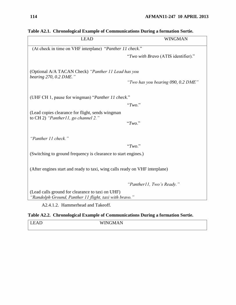
114 AFMAN11-247 10 APRIL 2013
Table A2.1. Chronological Example of Communications During a formation Sortie.
LEAD WINGMAN
(At check in time on VHF interplane) “Panther 11 check.”
“Two with Bravo (ATIS identifier).”
(Optional A/A TACAN Check) “Panther 11 Lead has you
bearing 270, 0.2 DME.”
“Two has you bearing 090, 0.2 DME”
(UHF CH 1, pause for wingman) “Panther 11 check.”
“Two.”
(Lead copies clearance for flight, sends wingman
to CH 2) “Panther11, go channel 2.”
“Two.”
“Panther 11 check.”
“Two.”
(Switching to ground frequency is clearance to start engines.)
(After engines start and ready to taxi, wing calls ready on VHF interplane)
“Panther11, Two’s Ready.”
(Lead calls ground for clearance to taxi on UHF)
“Randolph Ground, Panther 11 flight, taxi with bravo.”
A2.4.1.2. Hammerhead and Takeoff.
Table A2.2. Chronological Example of Communications During a formation Sortie.
LEAD WINGMAN

AFMAN11-247 10 APRIL 2013 115
(Checklist complete and ready.)
“Panther 11, Two’s Ready.”
(Call tower on UHF Ch 3) “Randolph Tower,
Panther 11 Flight, ready for takeoff, Rwy 14L,
“15 sec interval” or “one minute interval.”
(When in position on the runway)
“Panther 11, Two’s ready.”
(When cleared for takeoff, call over VHF)
“Panther 11, run 'em up.”
“Two.”
(After checking engine instruments)
“Panther 11, Two's ready”
A2.4.2. Airborne.
A2.4.2.1. Departure.
Table A2.3. Chronological Example of Communications During a formation Sortie.
LEAD WINGMAN
(At field boundary): “Panther 11 passing (altitude)
for (cleared altitude)” (15 second interval) or “Panther 11
passing (altitude) for (cleared altitude), “Panther 12 is one
minute in trail”(1 min interval)
(When in visual position, call over VHF)
“Panther 11, Two's in.”
(Departure calls out “Panther 11 contact Houston center on 132.8”)
“Panther 11, go 132.8.”
“Two.”
(On Channel 132.8) “Panther 11 check.”
“Two.”
“Houston center Panther 11 flight FLxxx”
A2.4.2.2. Area Maneuvers.
Table A2.4. Chronological Example of Communications During a formation Sortie.
LEAD WINGMAN

116 AFMAN11-247 10 APRIL 2013
Cell Maneuvering Cell Maneuvering
(Direct wing to cell, provide altitude, heading,
and airspeed) “Panther 11, go cell, base altitude
FL220, heading 180, 220 knots.”
“Two.”
(After hearing two's acknowledgement, begin the turn)
(When established in cell) “Panther 11,
two’s in.”
Practice Lost Wingman Practice Lost Wingman
“Panther 11, go practice lost wingman.”
(Acknowledge call first) “Two.”
(Execute procedures, advise lead
to level off or roll out as necessary)
“Panther 11, two is practice lost
wingman, lead roll out.”
(Acknowledge with altitude, heading,
airspeed, and aircraft attitude) “Panther 11 lead is
FL260, heading 340, 220 KIAS, wings level.”
“Two.”
(When lead is in sight and finished with
PLW)
“Panther 11, two is visual.”
(When ready for rejoin, direct type of rejoin)
“Panther 11, rejoin right turning.”
“Two.”
(Once in visual position) “Panther 11,
Two's in.”
Offset Maneuvering Offset Maneuvering
“Panther 11, go offset maneuvering.”
“Two”
(Once ready w/power set) “Panther 11,
Two’s in.”
A2.4.2.3. Note: For rejoins, breakouts, cell turns, and lead changes, lead will direct
wingman for the specific maneuver and the wingman will acknowledge with a read back
and/or his call sign.
A2.4.2.4. Note: Some example cell calls from lead are:
A2.4.2.4.1. “Panther 11, right/left turn heading_____” (standard cell turn)
A2.4.2.4.2. “Panther 11, new base heading______” (for area orientation)
A2.4.2.4.3. “Panther 11, continue to heading______” (to continue turn)

AFMAN11-247 10 APRIL 2013 117