by Md. Mehedi Hasan ID:1653555
83
Zn and Cu Co-Doped Li 4 Ti 5 O 12 Anode Material for Lithium Ion Batteries by Md. Mehedi Hasan ID:1653555 A thesis submitted in fulfillment of the requirements for the degree of Master of Science in Chemistry Khulna University of Engineering & Technology Department of Chemistry June 15, 2019
Transcript of by Md. Mehedi Hasan ID:1653555

Zn and Cu Co-Doped Li4Ti5O12 Anode Material for Lithium Ion
Batteries
by
Md. Mehedi Hasan
ID:1653555
A thesis submitted in fulfillment of the requirements for the degree
of Master of Science in Chemistry
Khulna University of Engineering & Technology
Department of Chemistry
June 15, 2019

II
Dedicated
To
My Beloved Parents

Declaration
This is to certify that the thesis work entitled "Zn and Cu Co-Doped Li4Ti5O12 Anode
Material for Lithium Ion Batteries" has been carried out by Md. Mehedi Hasan in the
Department of Chemistry, Khulna University of Engineering & Technology, Khulna,
Bangladesh. The above thesis work has not been submitted anywhere for the award of
any degree or diploma.
Signature of Supervisor Signature of Candidate
ô\ 9 Prof. Dr. Mohammad Abu Yousuf
Department of Chemistry Khulna University of Engineering &
Technology Khulna-9203, Bangladesh
Md. Mehedi Hasan Roll No.: 1653555
Department of Chemistry Khulna University of Engineering &
Technology Khulna-9203, Bangladesh

Approval
This is to certify that the thesis work submitted by Md. Mehedi I-Iasan entitled "Zn and Cu Co-doped Li4Ti5012 Anode Material for Lithium Ion Batteries" has been approved by the board of
examiners for the partial fulfillment of the requirements for the degree of M.Sc. in the Department of
Chemistry, Khulna University of Engineering & Technology, Khulna, Bangladesh.
BOARD OF EXAMINERS
Prof. Dr. Mohammad Abu Yousuf Department of Chemistry Khu lna University of Engineering & Technology
2._ Head
Department of Chemistry
Khulna University of Engineering & Technology
Prof. Dr. Md. Mizanur Rahman Badal
Department of Chemistry
Khulna University of Engineering & Technology
Dr. A. B. M. Mamun Jamal Assistant Professor Department of Chemistry
Khulna University of Engineering & Technology
Chairnan (Supervisor)
Member
Member
Member
5. Dr. Md, Mominul Islam
Associate Professor Department of Chemistry University of Dhaka
Member
(External)

V
Acknowledgements
All the admirations are for almighty Allah, who helped me in difficulties and gave me
enough strength and ability to accomplish this research work.
First and foremost I would like to extend my sincere gratitude to my thesis advisor Dr.
Mohammad Abu Yousuf, Professor, Department of Chemistry, Khulna University of
Engineering & Technology. I thank him immensely for his excellent guidance, support
and valuable suggestions throughout this endeavor, which nurtured a lot of confidence in
me.
I would like to thank Prof. Dr. Mohammad Hasan Morshed, Head, the Department of
Chemistry, KUET and the staff of the department for their continuous support during my
thesis work. I would like to give my special thanks to Parbhej Ahmed, Assistant
Professor, Department of Chemistry, KUET for his excellent support, laboratory
facilities, advice and enthusiasm throughout my M.Sc. I am indeed grateful to all my
dear teachers of the Department of Chemistry, KUET who triggered my interest in the
subject and was my real inspiration for doing research.
I would like to thanks University Grant Commission and Khulna University of
Engineering & Technology for funding my research.I sincerely thank all my labmates
and friends for their sincere co-operation and encouragement.
Many thanks to Samina Ahmed, Director (In-charge), Dhaka Laboratories, BCSIR,
Dhanmondi, Dhaka for the assistance concerning the XRD and and SEM-EDX
measurement of LTO composites.
Finally, last but not the least I would like to thank my parents and my family members
who have always been encouraging me in all aspects of life.
Md. Mehedi Hasan

VI
ABSTRACT
Lithium-ion batteries have been advanced the battery technology because of their
prevalent power sources for electric vehicles and portable electronics devices. Spinel
structure of lithium titanium oxide Li4Ti5O12 (LTO) has commended significant interest
as an anode material for lithium-ion batteries because of several advantages such as high
energy density, high safety, good chemical stability, long-life time, a flat operating
voltage about 1.55 V and low cost. Modification of the surface structure of LTO based
anode material by Cu and Zn has been significantly enhanced the conductivity of the
electrode material by suppressing the decomposition of the electrode material and
influencing their phase structure in some cases. Advanced spectroscopic techniques, such
as Fourier-Transform Infrared Spectroscopy (FTIR), scanning electron microscopy
(SEM), (EDX) and X-ray diffraction (XRD) are applied for the characterization of
morphology, particle size and crystal structure of the prepared LTO based anode
materials.
In the finger print region sharp low frequency characteristic IR bands observed below
800 cm-1
which can be attributed to the symmetric stretching vibrations of Ti-O bonds of
TiO6 octahedron in pure Li4Ti5O12, Li4Ti4.9Cu0.05Zn0.05O12, Li3.9Ti5Cu0.05Zn0.05O12 and
Li3.9Ti4.9Cu0.1Zn0.1O12. At the same time strong stretching bands at around 2360.87,
2341.58 and 2331.94 cm-1
can be assigned to the Ti-O-Ti bonds in the prepared LTO and
LTO based anode materials and corresponds to the published results.
Li4Ti5O12 possess a face-centered cubic spinel structure grounded on space group
symmetry of Fd3m. In the Li4Ti5O12 spinel structure, tetrahedral 8a sites are completely
taken up by Li and the octahedral 16d sites are arbitrarily occupied by Li and Ti with an
atomic ratio of 1:5 in a cubic close-packed oxygen array. The characteristic X-ray
diffraction peaks of the prepared samples are found at 2θ of 18.3, 35.58, 43.2449, 43.1,
57.2065, 62.8447, and 66.1006 which correspond to the planes (111). (311), (400), (333),
(440) and (531), respectively. The lattice parameter values were calculated for Li4Ti5O12,
Li4Ti4.9Cu0.05Zn0.05O12, Li3.9Ti5Cu0.05Zn0.05O12 and Li3.9Ti4.9Cu0.1Zn0.1O12 and the values
are 8.3692 Å, 8.3742 Å, 8.3834 Å and 8.3709 Å, respectively. XRD spectra that both
pure Li4Ti5O12 and Cu & Zn co-doped LTOs showed peaks representing single phase of
spinel lithium titanium oxide (cubic phase, space group Fd-3m) which are in good

VII
agreement with Joint Committee on Powder Diffraction Standards, JCPDS (No. 26-
1198) data.
SEM photographs of prepared pure LTO (Li4Ti5O12), Li4Ti4.9Cu0.05Zn0.05O12,
Li3.9Ti5Cu0.05Zn0.05O12 and Li3.9Ti4.9Cu0.1Zn0.1O12 possess chips like shape. No significant
change happened in the morphologies due to the co-doping of different ratio of Cu & Zn
into Li4Ti5O12. The morphologies of all prepared LTOs are almost same that correspond
the X-ray diffraction result.

VIII
Contents
Page
Title Page
I
Declaration
II
Acknowledgement
V
Abstract
VI
Contents
VIII
List of Tables
X
List of Figures
XI
List of Symbols and Abbreviations
XIII
CHAPTER I Introduction Page
1.1 General 1
1.2 Lithium Ion Batteries 1
1.3 Lithium Ion Battery Components 2
1.4 Opportunities in Lithium Ion Batteries 5
1.5 Motivation for LTO as Anode Material 6
1.6 Structure of LTO 7
1.7 Phase Transition Behavior of Li4Ti5O12 and
Li7Ti5O12
8
1.8 Why Rechargeable Li-Ion Battery? 10
1.9 Working Principle of Li-Ion Battery 11
1.10 Cathode 13
1.10.1 Layered Structured Cathode 14
1.10.2 Spinel Structured Cathode 15
1.10.3 Olivine Structured Cathode 15
1.11 Anode 15
1.11.1 Metallic Li Anode 16
1.11.2 Carbonaceous Anode 16
1.11.3 Sn and SnO2 Based Anode 17

IX
1.11.4 Lithium Titanate Anode 17
1.11.5 Other Metal Oxide Anode 18
1.11.6 Graphene-Based Anode 18
1.12 Various Methods of Synthesizing LTO 18
1.13 Synthesis of LTO Using Sol-gel Method 20
1.14 Characterization Ttechniques 22
1.14.1 Fourier-Transform Infrared Spectroscopy (FTIR) 22
1.14.2 X-ray Diffraction (XRD) 23
1.14.3 Scanning Electron Microscopy (SEM) 25
1.15 Electrochemical Characterization Using Cyclic
Voltammetry
28
CHAPTER II Literature Review
2.1 Development History of Battery 30
2.2 Modification of LTO 32
2.3 Atomic Doping of Li4Ti5O12 32
2.4 Transition Metal Doping 33
2.5 Doped by Metal in the Main Group 37
2.6 Doped by Non-metal in Carbon Group 38
2.7 Purpose of the Research Work 40
CHAPTER III Experimental
3.1 Chemicals 41
3.2 Characterization Equipment 42
3.3 Preparation Method for LTO Based Anode
Material
42
3.4 Fabrication of Electrode 44
CHAPTER IV Results and Discussion
4.1 FTIR Spectra Analyses of Prepared LTO Based
Materials
45

X
4.2 XRD Spectra Analyses of Prepared LTO Based
Materials
49
4.3 SEM Analysis 56
4.4 Prepared LTO Based Materials Electrochemical
Works
58
CHAPTER V Conclusions 60
References 61
List of Tables
Table No. Description Page
1.1 Crystal Structure data for spinel-LTO and rock-salt LTO 8
1.2 Properties of LTO synthesized by different methods in
terms of particle size and shape, electrochemical
performance
19
2.1 History of electrochemical cell development 30
2.2 The properties of LTO doped by transitional metal 33
2.3 Comparison of discharge capacity and cycling stability of
the LTO and doped Cu- LTO anode materials
36
2.4 Doping properties of LTO by metal in the main group 37
3.1 List of all chemicals 41
3.2 Information of the instruments used in this experiment 42
4.1 FTIR data analysis for LTO 48
4.2 List of important peaks of the prepared Li4Ti5O12 52
4.3 List of important peaks of the prepared
Li4Ti4.9Cu0.05Zn0.05O12
53
4.4 List of important peaks of the prepared
Li3.9Ti5Cu0.05Zn0.05O12
54
4. 5 List of important peaks of the prepared
Li3.9Ti4.9Cu0.1Zn0.1O12
55

XI
List of Figures
Figure No. Description Page
1.1 A simple schematic presentation of storage and charge/
discharge mechanism in a conventional lithium ion battery
comprised of a metal oxide cathode vs graphitic anode.
Charge is indicated by green arrows and discharge is
indicated by red arrows for the electrons and the ions
2
1.2 Unit cell of Li4Ti5O12 ([Li]8a[Li1/3Ti5/3]16dO4) (a) and
Li7Ti5O12 ([Li2]16c[Li1/3Ti5/3]16dO4) (b). The stable frame of
[Li1/3Ti5/3]16dO4 is shown as an octahedron and [Li]8a is
centered in a tetrahedron
7
1.3 Crystal structures of Li4Ti5O12 and Li7Ti5O12 9
1.4 Illustration of the charging/discharging process of LTO 10
1.5 General working principle of the charging/discharging
process of a rechargeable lithium-ion battery
11
1.6 FTIR Machine 22
1.7 XRD Machine 24
1.8 Schematics of Bragg`s Law for the scattering of X-rays at
periodic crystal lattice planes
24
1.9 Picture of a scanning electron microscope machine 26
1.10 Working procedure of SEM 27
1.11 Schematic diagram of a SEM 28
1.12 Cyclic Voltammogram response for a reversible redox
couple
29
3.1 Pictorial view of the synthesized LTO based composite
materials
44
4.1 FTIR spectrum of pure Li4Ti5O12 46
4.2 FTIR spectrum of Li4Ti4.9Cu0.05Zn0.05O12 47
4.3 FTIR spectrum of Li3.9Ti5Cu0.05Zn0.05O12 47
4.4 FTIR spectrum of Li3.9Ti4.9Cu0.1Zn0.1O12 48

XII
4.5 Crystal structure of spinel LTO with Fd3m space group.
Black: Li+. Octahedron with 16d and 16c site share
common edge 16d and 16c site share common faces with
tetrahedron 48f. Lithium can transport through 8a site to16c
site and vice versa
49
4.6 (a) Li4Ti5O12 spinel structure type. Blue tetrahedra
represent lithium and green octahedra represent disordered
lithium and titanium (b) Li7Ti5O12 rock salt. Blue octahedra
represent lithium and green octahedra represent disordered
lithium and titanium
50
4.7 XRD spectrum of pure Li4Ti5O12 52
4.8 XRD spectrum of Zn & Cu co-doped Li4Ti4.9Cu0.05Zn0.05O12 53
4.9 XRD spectrum of Zn & Cu co-doped Li3.9Ti5Cu0.05Zn0.05O12 54
4.10 XRD spectrum of Zn & Cu co-doped Li3.9Ti4.9Cu0.1Zn0.1O12 55
4.11 SEM image of pure Li4Ti5O12 at different magnifications 56
4.12 SEM image of Cu and Zn doped Li4Ti4.9Cu0.05Zn0.05O12
(LTO) at different magnifications
57
4.13 SEM image of Cu and Zn doped Li3.9Ti5Cu0.05Zn0.05O12
(LTO) at different magnifications
57
4.14 SEM image of Cu and Zn doped Li3.9Ti4.9Cu0.1Zn0.1O12
(LTO) at different magnifications
58
4.15 Fabricate cell 58
4.16 Cyclovoltammogram of the fabricated cell 59

XIII
List of Symbols and Abbreviations
LIB Li-ion battery LTO Lithium Titanium Oxide EC Ethylene Carbonate PC Propylene Carbonate
DMC Dimethyl Carbonate DEC Diethyl Carbonate EC Ethylene Carbonate
EMC Ethyl Methyl Carbonate LiPF6 Lithium Hexafluorophosphate PVDF Polyvinylidene Fluoride
NMP N-methylpyrrolidine
TEA Triethanol Amine
XRD X-ray Diffraction SEM Scanning Electron Microscopy FTIR Fourier-Transform Infrared Spectroscopy SE Scattered Electron PVDF Polyvinylidene Fluoride
JCPDS Joint Committee of Powder Diffraction Standards
λ Wavelength θ Angle Between incident X-ray beam and crystallographic planes n Order of the diffraction peak d Distance
h, l & k Miller Indices a Lattice Parameter

1
Chapter – I
Introduction
1.1 General
The ever increasing demand of the portable electronics industry, the electric vehicle
market and storage for alternative energy sources has put energy storage devices at
the lead of technological investigations [1]. Although there may be many ways to
store the uneven power that is from different energy resources, the demands and route
of progress of the moveable electronic and electric vehicle industries relies
profoundly on electrochemical storage devices, both batteries and super capacitors.
This essential on electrochemical storage devices and the necessity to shift toward
higher energy density and low mass devices has specifically intensive research
attention on solid state devices e.g., lithium ion batteries, Nickel ion batteries etc.
1.2 Lithium Ion Batteries
Li-ion battery (LIB) is a type of rechargeable battery, first suggested by chemist M
Stanley Whittingham at Exxon in the 1970s [2]. Whittingham used titanium (IV)
sulfide and lithium metal as the electrodes. However, this rechargeable lithium battery
could never be completed practical. But efforts to create re-chargeable LIBs followed
in the 1980s, although these failed due to the intrinsic changeability of the packs
along with the resulting safety concerns. Next important analysis on re-chargeable
LIB packs throughout the 1980s and finally SONY manufactured and sold the initial
Li-ion battery for commercial consumption in 1991. Since then a vast development
occurred in storage energy sector in the name of LIBs. People are using it frequently
in mobile phones, laptops and tablets, cameras, handheld game consoles, torches,
cordless drills, sanders, saws, multiplicity of garden equipment, rechargeable
cars, hybrid vehicles, electric motorcycles, scooters, electric bicycles, electric
wheelchairs, model aircraft etc. and when they required. It has vast uses and
advantages such as, relatively higher energy density, capability for still superior
capacities, quite low self-discharge, minimal upkeep, no irregular discharge is
required, no memory etc.

2
In LIB lithium ions transfer from the negative electrode to the positive electrode
during discharge and back after charging (Figure 1.1). Lithium ion electrodes are
conventionally intercalation materials where the lithium ions present in between the
layers and spaces in the lattice structures of the host material. A material’s propensity
to accept lithium ions inside its structure defines its storage capacity and capability as
an electrode material.
Li4-xTi5-xCuxZnxO12 Li-metal
1.3 Lithium Ion Battery Components
The three key functional elements of lithium ion batteries are cathode, anode, and
electrolyte. The cathode is the positive electrode that is condensed through the
reaction, and the lithium ions are deposited within the cathode when the cell is
discharged. Transition metal oxides have traditionally been the material of special for
Figure 1.1: A simple schematic presentation of storage and
charge/discharge mechanism in a conventional lithium ion battery
comprised of a metal oxide cathode vs graphitic anode. Charge is indicated
by green arrows and discharge is indicated by red arrows for the electrons
and the ions [3]

3
cathodes used in high energy density applications. Yet there is soft motivated
attention to identify and improve anode and cathode materials that growth the energy
density further, while enlightening rate capability and security. There are numerous
key abilities of any good cathode material, namely, the cathode must agree for
noteworthy and unchanging reversible intercalation of lithium ions; exhibit low
electron energy and site energy for Li-ions; electrode potential should fluctuate little
with Li+ content; determine fast diffusion of electrons and Li
+; stable over operating
voltage range; low cost; lack of harmfulness; comfort of preparation and
reproducibility; and promising interface designed at contact with electrolyte [4].
Different cathode materials such as LiCoPO4, LiMnPO4, LiCoO2, LiNiO2, Li have
been inspected to report many of these contributing factors, each offering distinctive
benefits, but also exposing possible drawbacks. Manganese oxide chemistries,
LiNiO2, LiMnO2, and spinel LiMn2O4 have their individual advantages in safety and
cost; though the lower capacity, as matched to the lithiated cobalt-oxide chemistry, is
one disadvantage [5]. Vanadium oxide chemistries can occur in a variety of phases
and have been used as electrode materials also. Though they have high capacities,
their voltages are usually lower than the transition metal oxides, manufacture them
appropriate for only certain uses [4]. Moreover, novel phosphate chemistries have
been established and initiate appropriate for applications demanding advanced power
capabilities; LiMnPO4 and LiCoPO4 exhibit higher open circuit voltages over metal
oxide chemistries, in the range of 4.1 – 4.9 V [5]. Specially, LiFePO4 meets many of
the measures for actual cathode materials, exactly its capability to cycle well at high
current rates, its durability against overcharge assembly it a much harmless material,
and its cheap manufacture costs.
The anode is the negative electrode that is oxidized during the battery discharge
reaction and where the lithium ions are stored when the cell is fully charged. The
evolution of lithium ion batteries from lithium batteries came about primarily from the
shift in anode material toward carbonaceous or lithium alloy materials and away from
pure lithium metal. The low voltage versus lithium of a variety of carbonaceous
materials led to the investigation and use of graphite, carbon fibers and meso carbon
micro beads as the active material in commercial anodes. Graphite materials tend to
be efficient intercalation materials, and the mechanism of storage that results in the
stoichiometry of LiC6 and a theoretical storage capacity of 372 mA.h.g-1
in these

4
materials is well understood [4]. Additionally, carbon anodes have been an excellent
initial choice because of their high storage capacity, low cost, long cycle life, small
volume change of < 9 % upon lithiation, and negative reduction-oxidation potential
versus the cathode. In regards to lithium alloys, Group III, IV, and V elements have
been studied because of their capability to store lithium at low voltages LiAl and LiSn
systems were initially examined and followed shortly by silicon because it
confirmations the highest possible gravimetric capacity over 4000 mA.h.g-1
[6].
In spite of the potential for high voltage batteries and huge gravimetric capacities with
these anode materials there is inadequate large scale commercial usage of these alloy
materials. The primary cause is because a large volumetric expansion is related with
each of these elements upon lithiation oscillating from 100 to 400 % depending on the
specific material. With an extension that great during lithiation, the electrode easily
cracks and delaminates from the current collector interpreting the battery ineffective.
Current investigations into overcoming this problem have led to a multiplicity of other
anode materials for lithium ion battery. Recently, spinel lithium titanium (LTO) have
involved more and more consideration as a potential anode material for lithium ion
batteries, attributes to nits outstanding structural stability (no structural or volume
change during Li insertion and extraction) and no risk of lithium plating during the
fast charge/discharge rate with 1.55 V vs Li+/Li reduction potential of LTO [7]. In
evaluation to carbonaceous anode, spinel lithium titanium LTO has well
electrochemical performance and higher safety. It is cheaper and easier to be
manufactured correlated with alloy-based anode in lithium ion batteries. Researchers
have specified that LTO would be a good alternative for graphite in high-safety LIBs.
To our best knowledge, it was studied as early as in 1984 by Edwards et al, [8] then
planned to be cathode in 1989 by Colbow and coworkers. In 2005, it became firstly
commercialized by Altairnano Corporation, who substituted traditional graphite
materials for anode material.
The electrolyte and separator combination within a lithium ion battery is a key
component which requires some important considerations for optimal battery
performance. The ionic conductivity of the electrolyte should be high to reduce
internal cell resistance. In addition the permanence of the electrolyte is an important
factor in two ways; a) a high chemical stability stops decomposition of the electrolyte

5
on highly reducing anodes or oxidizing cathodes, and b) a large voltage window of
electrochemical stability as determined by the voltage difference between the cathode
and anode (typically > 4 V). Furthermore a low melting point and a high boiling point
can deliver sufficient conductivity and improve the battery safety by avoiding
solidification of the electrolyte and explosive reactions at high temperatures. Non-
toxicity of the electrolyte in terms of environmental concerns and ease of handling
permit for the scale-up usage of a suitable material, and lastly, an electrolyte at an
inexpensive cost as matched to other power sources will aid in its marketable capability
[9].
While a host of lithium salts exist, most exhibit detrimental characteristics for battery
performance (i.e. toxic side chemical reactions in the solvents); lithium hexafluoro
phosphate (LiPF6), being the least damaging, is widely used in electrolyte chemistries.
Lithium bis (oxyalato) borate is another potentially effective salt, and along with
LiPF6, used in concentrations of 0.4 to 1M [10]. LiPF6 works well in a voltage range
of 0 – 4.5 V because of its high electrochemical stability, but its thermal stability
raises concerns in addition to its extreme sensitivity to water which can lead to the
formation of hydrofluoric acid within the cell causing performance degradation.
Organic carbonates are suitable and have been widely investigated in lithium ion
batteries; ethylene carbonate (EC), propylene carbonate (PC), dimethyl carbonate
(DMC), diethyl carbonate (DEC), ethyl methyl carbonate (EMC), and more recently
γ-butyro lactone (GBL) are commonly used electrolyte solvents, most often found in
binary or ternary solvent systems [11]. Non-aqueous electrolytes generally are used
non-coordinating anion salts such as lithium hexafluorophosphate (LiPF6), lithium
perchlorate (LiClO4), lithium hexafluoroarsenate monohydrate (LiAsF6), lithium
tetrafluoroborate (LiBF4), and lithium triflate (LiCF3SO3). Combinations of cyclic and
linear carbonates demonstrate enhanced performance, particularly at lower
temperatures, over single solvent electrolytes; this improved performance is attributed
to the decrease in viscosity as a linear carbonate is combined with a cyclic one.
1.4 Opportunities in Lithium Ion Batteries
The demand for smaller storage devices continues to grow and there are ongoing
investigations into developing superior materials to meet the industries demands of
small and high performance devices. The development of batteries has progressed

6
slowly because of many obstacles posed by cost, safety, and environmental
compatibility. The potential to improve battery performance lies in several areas of
battery development, with active materials and electrolyte chemistries being two with
the biggest opportunities for growth. Because each of these fields is enormous in their
breadth, a detailed and thorough investigation of any one specific area necessitates
limiting the scope of study. This work will focus on the development from synthesis to
device testing of high storage capacity nanomaterial for their use in lithium ion battery
anodes to increase the energy and power density of the anode and in turn the full cell.
1.5 Motivation for LTO as Anode Material
The commercial anode material of LIBs is graphite. Graphite can accommodate Li+
ions to form LiC6 and provides a specific capacity of 372 mA.h.g-1
. The intercalation
reaction of Li+ ions into graphite occurs at the potential of around 0.5~0.6 V vs Li
+/Li.
Lithium deposition, however, may take place to form lithium dendrites on graphite at
such low potential. Lithium dendrites can penetrate the separator resulting in a short
circuit. The electrolytes with special additives can be decomposed to form a solid
electrolyte interface (SEI) film and this SEI film on the surface of graphite can
prevent the formation of lithium dendrites. On the other hand, the stability of the SEI
film and undesired structural changes in graphite (e.g., exploitation or non-active
sites) during the charging and discharging process are detrimental to safety and
lifetime of LIBs [12]. Therefore seeking an alternative anode material has attracted
more and more attention.
A large number of candidates for anode materials have been extensively studied over
the past two decades. In brief, these candidates can be divided into several categories:
alloy reaction materials such as Si, Sn, Sb and Ge; conversion reaction materials such
as iron oxide, nickel oxide, and cobalt oxide; and intercalation reaction materials such
as lithium titanate spinel (LTO) and anatase (TiO2). Alloy anode materials have an
ultra-high specific capacity, which can be up to 10 times higher than that of graphite.
On the other hand, the volume of alloy anode materials expands 2 to 3 times after the
full lithiation, for instance, 3.2-fold expansion for Si and 2.6-fold expansion for Sn.
The considerable volume change during lithiation/delithiation reaction will bring
about a pulverization and isolation of active materials in the electrode, leading to a
poor cycle stability [13]. Transition metal oxides such Fe2O3, CuO and CoO can

7
undergo reversible reduction in the presence of Li+ ions, delivering 2 or 3 times
higher specific capacity than that of graphite [14]. Metal sulfides, phosphides and
fluorides have been proven to be able to undergo such reaction as well. The low
Coulombic efficiency and cycle stability derived from the irreversible phase
transformation at the reduction process impede their application. Further the other
promising candidates for anode materials are intercalation reaction materials. More
and more attention have been paid to the Ti-based materials such as LTO and TiO2
(e.g., anatase, rutile, brookite, TiO2-b and even amorphous), attributed to their
structural stability during the intercalation reaction [15].
1.6 Structure of LTO
LTO was first reported as an anode material for LIBs in 1994, and since then
numerous studies have been carried out in order to learn its electrochemical and
structural properties [16]. Li+ ions can be reversibly inserted into and extracted from
LTO at a potential of 1.55 V vs Li+/Li. The high intercalation potential of LTO
prevents lithium deposition and electrolyte decomposition, which is crucial for
electrode durability and safety. The spinel structure of Li4Ti5O12 (Fd3 m) comprises
eight formula units of (Li)8a
[Li1/3Ti5/3]16d
O432e
per unit cell, in which Li+ entirely
occupies 8 tetrahedral (a) sites, while the 16 octahedral (d) sites are occupied by one-
third Li+ and five-third Ti
4+ (seeing Figure 1.2). The remaining oxygen ions on 32e
sites from a cubic close-packed structure. Intriguingly, during the lithiation,
Figure 1.2 Unit cell of Li4Ti5O12 ([Li]8a[Li1/3Ti5/3]16dO4) (a) and Li7Ti5O12
([Li2]16c[Li1/3Ti5/3]16dO4) (b). The stable frame of [Li1/3Ti5/3]16dO4 is shown
as an octahedron and [Li]8a is centered in a tetrahedron.

8
the Li4Ti5O12 structure undergoes a change to [(Li)1−x8a
[Li]2x16c
[Li1/3Ti5/3]16d
O432e
],
which is accompanied by a minor volume expansion of ~0.2% due to the migration of
Li+ ions from tetrahedral (a) sites toward octahedral (c) sites [17]. The advantage of
LTO derived from structural stability as “zero strain” material enables safe operation,
high rate capacity and excellent cyclability.
1.7 Phase Transition Behavior of Li4Ti5O12 and Li7Ti5O12
Twenty years ago, Ohzuku and co-authors[18] reported that the charge/discharge
curve for Li4Ti5O12 (LTO) electrode as anode is characterized by a very flat and
extended voltage plateau at around 1.55 V, which is a typical characteristic of phase
transition between a Li-rich phase (Li7Ti5O12, rock-salt LTO) and a Li-poor phase
(Li4Ti5O12, spinel-LTO). Although substantial chemical changes occur during
conversion between the two phases, a negligible volume change of 0.2 - 0.3% occurs
between two phase changes accompanied by a change of the lattice from 0.8364 nm
to 0.8353 nm, and as a result it is called the “zero-strain insertion materials”, which
indicating that it is an excellent material with exceptional reversibility performance as
anode material for LIBs. As well investigated and discussed [19] three Ti4+
ions are
reduced to Ti3+
ions during the two-phase transition from spinel-LTO into rock-salt
LTO. The corresponding electrochemical reaction can be briefly described during the
lithium insertion and extraction processes as:
(Spinel-LTO) Li4Ti5O12 + 3Li+
+ 3e- ↔ Li7Ti5O12 (Rock-salt LTO)
Two types of LTO crystallographic data is summarized in Table 1.1 [20]. It is
Table 1.1: Crystal Structure data for spinel-LTO and rock-salt LTO [20]
Materials Atom Wyckoff (space
group) Site
Cell parameter Occupancy
x Y Z
Spinel-
LTO
(Fd3m)
Li1 8a 0.125 0.125 0.125 1.0
Li2 16d 0.5 0.5 0.5 0.01667
Ti 16d 0.5 0.5 0.5 0.8333
O 32e 0.2625(1) 0.2625(1) 0.2625(1) 1.0
Rock-salt
LTO
Li1 8a 0 0 0 1.0
Li2 16d 0.5 0.5 0.5 0.1667

9
(Fd3m) Ti 16d 0.5 0.5 0.5 0.8333
O 32e 0.2576(3) 0.2576(3) 0.2576(3) 1.0
apparent that spinel-LTO and rock-salt LTO has very similar crystallographic
parameters, which demonstrate the structural stability during the charge/discharge
processing when LTO electrode is applied as anode.
Figure 1.3: shows the structure of spinel LTO crystallized in the space group (Fd3m).
[18, 21] Lithium ions and titanium ions randomly occupy the octahedral (16d) sites,
while the tetrahedral (8a) sites are occupied by lithium. As three lithium ions insert
into spinel LTO and occupy the octahedral (16c) positions, the tetrahedral lithium
ions of Li4Ti5O12 are shifted to the octahedral (16c) sites and LTO crystallizes in the
space group with ordered rock-salt structure, as shown in Figure 1.1. In contrast to
spinel structure, the octahedral 16d positions are still occupied by lithium ions and
titanium ions, whereas the tetrahedral (8a) sites in Li7Ti5O12 are free. They are
described by the cubic space group and have very similar lattice parameters (a =
0.83595 and 0.83538 nm, respectively) [18, 21].
Figure 1.3: Crystal structures of Li4Ti5O12 and Li7Ti5O12 [21]
Spinel LTO is a good lithium ion conductor (10-6 cm2/s) and very poor electronic
conductor (10−8
S/cm) [22] because of the existence of available free octahedral (16c)
sites in its lattice and the oxidation state of Ti4+
. On the other hand, Li7Ti5O12 is a
good electronic conductor (10−2
S/cm) and poor lithium ion conductor because Ti3+
ions occupy 60% of all the oxidation state of Ti and the full 16c octahedral sites in the
lattice are occupied by Li+ ions.
10
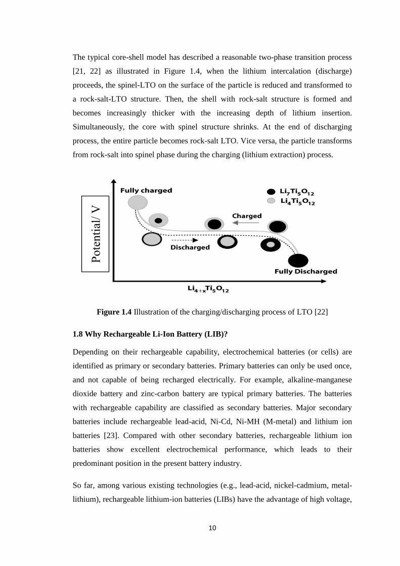
The typical core-shell model has described a reasonable two-phase transition process
[21, 22] as illustrated in Figure 1.4, when the lithium intercalation (discharge)
proceeds, the spinel-LTO on the surface of the particle is reduced and transformed to
a rock-salt-LTO structure. Then, the shell with rock-salt structure is formed and
becomes increasingly thicker with the increasing depth of lithium insertion.
Simultaneously, the core with spinel structure shrinks. At the end of discharging
process, the entire particle becomes rock-salt LTO. Vice versa, the particle transforms
from rock-salt into spinel phase during the charging (lithium extraction) process.
Figure 1.4 Illustration of the charging/discharging process of LTO [22]
1.8 Why Rechargeable Li-Ion Battery (LIB)?
Depending on their rechargeable capability, electrochemical batteries (or cells) are
identified as primary or secondary batteries. Primary batteries can only be used once,
and not capable of being recharged electrically. For example, alkaline-manganese
dioxide battery and zinc-carbon battery are typical primary batteries. The batteries
with rechargeable capability are classified as secondary batteries. Major secondary
batteries include rechargeable lead-acid, Ni-Cd, Ni-MH (M-metal) and lithium ion
batteries [23]. Compared with other secondary batteries, rechargeable lithium ion
batteries show excellent electrochemical performance, which leads to their
predominant position in the present battery industry.
So far, among various existing technologies (e.g., lead-acid, nickel-cadmium, metal-
lithium), rechargeable lithium-ion batteries (LIBs) have the advantage of high voltage,
Potential/ V

11
long cycling life, high power, high reliability and design flexibility (see Figure 1.4)
[24] the significance and popularity of the rechargeable lithium-ion batteries are
definitely resulted from its unique advantages offered over other secondary batteries:
Lighter than other rechargeable batteries for a given capacity
Li-ion chemistry delivers a high open-circuit voltage
Low self-discharge rate (about 1.5% per month)
Do not suffer from battery memory effect
Environmental benefits in rechargeable and reduced toxic landfill
1.9 Working Principle of Li-Ion Battery
Figure 1.5. General working principle of the charging/discharging
process of a rechargeable lithium-ion battery [25]
In general, there are five components that establish a lithium-ion cell. These
components are two electrodes, electrolyte, and two current collectors. The main
function of the electrodes is to be reduced or oxidized over a potential range measured
in volts (V). The electrolyte serves as an ionic conductor between the electrodes and
must be electronically insulating. The current collectors are an electrically conducting
material, usually a metal that are directly in contact with each electrode. The current
collectors are attached to each other by an external circuit (see Figure 1.5) [26]. A

12
lithium-ion battery exhibits the electrochemical cell functions because of the potential
difference between the two electrodes. It is energetically favorable for the two
electrodes to come towards an equilibrium potential that is lower than the initial open-
circuit cell potential where they are stable. Equilibrium between the electrodes is
achieved by the oxidation of one electrode and the reduction of the other electrode.
The electrode that is reduced is called the cathode, while the electrode that is oxidized
is called the anode. These reactions are accomplished by two distinct paths for ions
and electrons. The electrons travel through the external circuit from the anode to the
cathode. At the same time, the ions travel in the same direction as the electrons
between the two electrodes through the electrolyte. This completes the redox reaction
of the two electrodes, as showed clearly in Figure 1.5.
Usually, the basic working principle of lithium-ion batteries is based on lithium ion
(Li+) reversible de-intercalation and intercalation processes between two electrodes
[27]. As a result, during charge/discharge, Li+ ions movement between the anode and
the cathode, permitting the conversion of chemical energy into electrical energy and
the storage of electrochemical energy within the battery. Now, the electrolyte should
be ionically conducting and electronically insulating, however the actual properties of
the electrolyte are much more complex. During the first cycle, a solid–electrolyte-
interphase (SEI) layer will be formed on the surface of electrodes due to the
decomposition of organic electrolyte [27]. The typical electrochemical reactions
involved in a typical LIB cell are described in Figure 1.5.
The charge/discharge mechanism of a LIB is also known as a “rocking chair” concept
as Li+ ions “rock” back and forth between anode and cathode [28]. As is shown in
Figure 1.5, lithium ions are shuttled between anode and cathode through the
electrolyte during the charging and discharging processes. Lithium ions de-intercalate
from the cathode into the electrolyte during the charging process under an applied
current. Instantaneously, an equivalent amount of lithium ions from the electrolyte
introduce into the anode. The reverse reaction proceeds spontaneously when the
battery is discharged. On both of the charging and discharging process, charge
compensation is provided by the external circuit supply.
A LIB essentially consists of a cathode, an anode, electrolyte and a separator. The
cathode materials are commonly Li-containing transition metal oxides with a layered

13
structure (such as lithium cobalt oxide) or tunnel-structured materials (such as lithium
manganese oxide). The anode materials contain insertion-type materials (such as
graphite, TiO2, etc.), conversion-type materials (such as iron oxides, nickel oxides,
cobalt oxides, etc.) and alloying-type materials (such as Si, Sn etc.). The electrolyte is
hypothetical to be a good ionic conductor and electronic insulator. Most of the
electrolytes are founded on the solution of inorganic lithium salts liquefied in a
mixture of two or more organic solvents. The purpose of the separator is to prevent
short circuit between the two electrodes and to provide abundant channels for
transportation of Li ion during the process of charging/discharging.
1.10 Cathode
Cathode materials are typically Li-containing oxides of transition metals with layer
structure, which undergo oxidation reaction to higher valences when lithium is
removed. While oxidation of the transition metal can maintain charge neutrality in the
compound, large compositional changes often lead to phase changes, so crystal
structures that are stable over wide ranges of composition must be used. This
structural stability is a particular challenge during charging when most (ideally all) of
the lithium is removed from the cathode. During discharge lithium is inserted into the
cathode material and electrons from the anode reduce the transition metal ions in the
cathode to a lower valence. The key requirements for a successful cathode material in
a rechargeable LIB are as follows [29]:
1) The material contains a readily reducible/oxidizable ion, for example a
transition metal
2) The material reacts with lithium in a reversible manner
3) The material reacts with lithium with a high free energy of reaction
4) The material reacts with lithium very rapidly during both insertion and
extraction processes
5) The material is supposed to be a good electronic conductor, preferably a
metal
6) The material should be stable. For example, there won’t be structure
changing or degrading if over-discharging or over-changing takes place
7) The material should be less expensive
8) The material is better to be environmentally friendly

14
During the early age of LIBs, metal chalcogenides (e.g., TiS2 and MoS2) and
manganese or vanadium oxides were chosen as the cathode materials to pair with the
metallic Li or the graphite anode. After several decades development and the
increasing requirement of high-performance electrode material from large-scale
energy storage, the main focus on the cathode materials for LIBs has been devoted to
layered, structured hexagonal LiCoO2, spinel LiMn2O4, olivine LiFePO4, and their
derivatives.
1.10.1 Layered Structured Cathode
There are three basic layered cathode materials: LiCoO2, LiNiO2 and LiMnO2.
LiCoO2 has been and is still widely used in commercialized LIBs since it’s first
patented as a lithium intercalation cathode material in 1980 by good enough and its
first appearance in the commercial LIBs by SONY in 1991. It possesses the
advantages of large theoretical capacity (274 mAh·g-1
, calculated based on extraction
of 1 mole of Li+
from LiCoO2) and high working voltage (>3.4V). The cathode
undergoes serious phase transformation between hexagonal and monoclinic when the
cathode charged above 4.2 V. Since this phase transformation leads deterioration of
cycling performance, practical capacity is restricted as half of theoretical capacity.
Although the LiCoO2 cathode dominates the LIB market, there is a limited
availability of cobalt, which makes the cost of a single battery expensive. This price
limits its application only in the area of small cells of portable electrical devices, such
as those used in computers, cell phones, and cameras [29].
Lithium nickel oxide, LiNiO2, due to the configuration of low spin Ni3+
:t2g6eg
1,
electrons are removed only from the e.g. band that barely touches the top of the O2-
:2p
band, thus most of the lithium can be extracted from LiNiO2 prior to the oxygen loss
and a high capacity of around 200 mA.h.g-1
is generated [30]. LiNiO2 has the same
structure with lithium cobalt oxide but has not been pursued in the pure state as a
battery cathode for a variety of reasons, even though nickel is less expensive than
cobalt. First, it is not clear that stoichiometric LiNiO2 exists. Most reports suggest
excess nickel as in Li1-yNi1+yO2; thus, nickel is always found in the lithium layer,
which pins the NiO2 layers together, thereby reducing the lithium diffusion coefficient
and the power capability of the electrode. Second, compounds with low lithium

15
contents appear to be unstable due to the high effective equilibrium oxygen partial
pressure, so that such cells are inherently unstable and therefore dangerous in contact
with organic solvents [29]. There are two structures of LiMnO2, the layered structure
and the orthorhombic phase. The layered structure is thermodynamically more stable.
The layered LiMnO2 can be synthesized using the soft chemical method such as ion-
exchange from the sodium analogue NaMnO2 [31]. Generally speaking, the
manganese based material has advantages of low price and low toxicity and high
initial charge capacity. However the main shortcoming of the layered LiMnO2 is the
crystallographic transformation to more stable spinel structure during electrochemical
cycling. Mn3+
is a Jahn-Teller ion and the redox reaction between Mn3+
and Mn4+
will
result in local distortion and quick capacity decay [32].
1.10.2 Spinel Structured Cathode
LiMn2O4 is an extensively studied cathode material for LIBs. Compared with LiCoO2,
it possesses the advantages of cheaper price, lower toxicity, and higher rate capability.
However, the main drawback of spinel LiMn2O4 cathode is drastic capacity fading,
especially at high temperatures, and shows a low capacity of around 120 mAh·g-1
[33]. The dissolution of manganese from the lattice into the electrolyte due to a
disproportion of Mn3+
ions into Mn2+
and Mn4+
plays a vital role for the problem,
which is facilitated by trace amount of HF generated in the electrolyte [34].
1.10.3 Olivine Structured Cathode
In 1997, Good enough and co-workers firstly reported reversible lithium intercalation
in the phosphate poly anionic compound of LiFePO4. The Olivine-type of LiFePO4
with a theoretical capacity of 170 mAh·g-1
has been considered as a promising cathode
material for LIBs [35]. The main drawbacks of LiFePO4 are the poor conductivity
resulting from the low Li ion diffusion rate and low electronic conductivity.
1.11 Anode
Anode is the negative electrode of a primary cell and is always associated with
oxidation reaction, accompanying with release of electrons to external circuit. In a
secondary cell, anode is the negative pole during discharge but the positive pole
during charge. The basic requirements for a LIB anode material are that the material
should have minimal volume expansion and resulting stress during charge/discharge

16
process, high electronic conductivity, low irreversible capacity during initial charging
or intercalation process, stable under wide operating temperature window in a highly
reducing environment, and low specific surface area (typically < 2 m2/g) for optimal
performance and safety [36].
1.11.1 Metallic Li Anode
The most elementary anode material for lithium-based batteries is metallic lithium,
which has been used for primary batteries since the early 1960s. By possessing the
lowest standard potential (–3.05 V vs. a standard hydrogen electrode (SHE) and the
lowest atomic weight (6.94 g/mol specific gravity: ρ= 0.53 g/cm3) among all metals,
the utilization of metallic lithium as an anode offers the realization of galvanostatic
cells having an extremely high capacity (3820 mAh·g-1
) and energy density (1470
W·kg-1
) [37]. Consequently, metallic lithium was also considered as the candidate of
choice for secondary LIBs. However, lithium metal cells have one severe drawback,
namely, inhomogeneous lithium plating, which hinders their commercial
development. This uneven deposition of lithium onto the anode surface upon charge
results in the formation of so-called dendrites. And the disordered metallic deposit
gives rise to a poor Coulombic efficiency, resulting from such a fine Li metal often
acts as an active site inducing reductive decomposition of electrolyte components.
Part of the deposit may become electrically isolated and shedding may also occur.
These dendrites consist of high surface area, highly branched lithium metal structures,
which continuously grow, may easily penetrate into the separator and eventually
cause internal short, resulting in heat generation and contingent ignition. Hence the
hazardous nature of Li has paved way to explore some other safer anode materials,
possessing comparably the same electrochemical features as that of metallic lithium.
1.11.2 Carbonaceous Anode
The most commonly used anode material is carbonaceous materials as they possess
the advantages of low cost, excellent reversible capacity and long cycling life. Carbon
as an insertion anode material was first reported in 1973. Carbonaceous materials
have large variations in crystallinity, chemical composition and micro texture
depending on their preparation, processing, precursor, thermal and chemical
activation treatments. All carbonaceous materials are able to storing lithium ions [38].

17
Graphitic carbons are characterized by layers of hexagonally arranged carbon atoms
in a planar graphene layers. Graphite shows a rather flat potential profile when
reversibly hosting Li+ at potentials below 0.5 V vs. Li/Li
+. Additionally, it offers a
significantly higher specific capacity of 372 mAh/g (corresponding to one lithium per
hexagonal carbon ring, i.e. LiC6) [39]. The volume expansion during lithium
intercalation and extraction between the graphene layers is just over 10%, resulting in
high reversibility and stable capacity over repeated cycling. However, compared with
other alternative anode materials, the theoretical capacity of graphite is far behind to
meet the requirement from batteries with high energy density.
1.11.3 Sn and SnO2 Based Anode
Sn and SnO2 are promising anode materials with high theoretical capacity. The
reversible capacity of Sn is as high as 994 mA.h.g-1
when alloy Li4.4 Sn forms during
lithiation and the theoretical capacity of SnO2 is 782 mAh·g-1
[40]. However both Sn
and SnO2 suffer from severe volume change during cycling.
One of the most efficient approaches to alleviate the severe volume change and
stabilizing the structure is to design nano structured materials, for example, in the
form of nano tubes, nanorods, nano wires and hollow structures [40]. Although most
of the attempts have been made to synthesize new nanostructures for Sn and SnO2, up
to now most efforts have been characterized as having technical difficulties or high
synthesis costs, and most of them have proved not to be very successful in improving
the cycling stability of Sn and SnO2-based electrodes [41]. Adding coating materials
(such as carbon or other conductive materials) are another method to accommodate
volume changes. In addition, the electrical conductivity of the whole electrode could
also be enhanced [42].
1.11.4 Lithium Titanate Anode
Lithium titanate (LTO) is another promising anode material with spinel structure for
certain applications that require fast charging capability; first reported in 1994 [37]. It
has superior high rate performance with very long cycle life. It is being developed for
automotive and energy storage applications. Some of the challenges for the LTO-
based batteries include lower voltage (2.5 V vs. LiCoO2), lower capacity, and
excellent high-temperature stability [36].

18
1.11.5 Other Metal Oxide Anode
Apart from SnO2, other metal oxides, such as Co3O4, TiO2, NiO and Fe3O4 have been
studied. These metal oxides also suffer from severe aggregation and rapid capacity
fading due to dramatic volume expansion and low electrical conductivity [28]. The
most commonly studied methods to solve the problems are coating carbon layers on
the surface of the metal oxides or dispersing them into carbon matrix.
1.11.6 Graphene-Based Anode
Graphene is a single layer carbon nano sheet consisting of two equivalent sub-lattices
of sp2
carbon atoms connected by σ bonds. And theoretical calculation showed that
graphene possesses a maximum capacity of 740 mA.h.g-1
on the basis of a double-
layer adsorption configuration, which is much larger than that of layered graphite.
Sato and co-workers [43] used the 7 Li nuclear magnetic resonance (NMR) technique
to study lithium ion transport mechanism in a disordered carbon, and proposed a
model of Li2 covalent molecule configuration that a Li2 molecule is loosely trapped by
two adjacent benzene rings in the carbon. The most saturated Li storage state can be
LiC2 to give a capacity of up to 1116 mA.h.g-1
. Both two configurations suggest a
higher capacity of graphene anode. Another study showed that graphene and graphite
have a similar interaction mode with Li ions after analyzing in situ Raman spectra of
lithiation processes in both single and few-layer graphene anodes. However, because
of the repulsion forces between Li+
at both surfaces of graphene, the amount of
adsorbed Li on single-layered graphene is low. Uthaisar and Barone [44] studied the
edge effects of Li diffusion in graphene by means of density functional theory and
showed that narrower grapheme nano-ribbons, especially with a zigzag morphology,
can provide a faster discharge rate owing to the lowering of energy barriers and
diffusion lengths. The theories mentioned above can explain the Li storage
mechanisms to some extent; however, more work is still needed in the coming future
to erase the debate.
1.12 Various Methods of Synthesizing LTO
For synthesis of lithium titanium oxide different methods, including emulsion-gel
process, solid state method, hydrothermal or solvothermal method, spray pyrolysis,

19
composite molten-salt method, template method, reflux method, flux method,
mechanochemical synthesis, electro spinning method, solution combustion synthesis,
modified solution combustion synthesis, sono chemical method, single step metal
organic precursor method, template free hydrothermal process, spray drying process,
modified rheological phase method and electro spray pyrolysis method.
Sol-gel method is used for the synthesis of spinel LTO because this technique gives
the regular morphology, homogeneity and uniform particle size distribution. So this
technique is better than other techniques. Also there are some different kinds of
method have been developed for preparing LTO and this techniques exhibit excellent
electrochemical performance. LTO synthesis by different methods shows individual
characteristic based on particle size and shape, and electrochemical performance, as
summarized in Table 1.2.
Table 1.2: Properties of LTO synthesized by different methods in terms of particle
size and shape, electrochemical performance
Methods Particle
size (nm)
Shape Electrochemical performance Ref.
Solid-state
method
70 Spherical 202 mA.h.g-1
at 0.01-2.5 V [45]
Sol-gel method 98 – 136 Nanoparticle Excellent cycliability
272 mA.h.g-1
- first cycle
[46]
Sol-gel method
with different
complex agents
76 – 500 Round 170 mA.h.g-1
- first cycle
150 mA.h.g-1
- 30 cycles –
0.5 mA·cm-2
[47]
Refluxing
method
5 – 400 Spherical 200 mA.h.g-1
- 0.4 mA·cm-2
-
60th cycles
[48]
Heat treatment
and an alkali
hydrothermal
reaction
6 – 11 Nanotubes ∼156 mA.h.g-1
- 0.1 C [49]
Template-free
hydrothermal
process
20 Spherical 114 mA.h.g-1
- 30 C
125 mA.h.g-1
- 200 cycles - 20
C
[50]

20
Single step metal
organic precursor
method
>50 3-D ordered
macroporos
167 mA.h.g-1
- 1st cycle - 0.1
mA. cm-2
149 mA.h.g-1
- 0.125 mA.cm-2
155 mA.h.g-1
- 0.63 mA.cm-2
[51]
Carbon sphere
template method
100 – 500 Hollow
Spheres
100 mA.h.g-1
- 10 C
150 mA.h.g-1
- 2 C - 200 cycle
[52]
Electro spinning
method
230 – 270 Nan fibers 140-192 mA.h.g-1
- 0.5 C - first
five cycles with a capacity loss
of 1.0% percycle 87 - 170
mA.h.g-1
- first 30 cycles with a
capacity loss of 1.6% per cycle
at 1.5 C
[53]
Spray pyrolysis 980 Spherical 171-168 mA.h.g-1
– 50 cycle by
heating at 800 ºC
Decreased from 172 to 129
mA.h.g-1
for 1000 ºC heating
LTO heated at 600, 800 ºC
have good retention capacity
value on cycling while treating
at 1000 ºC has poor cycle
properties
[54]
Composite
molten salt
method
500-3000 Octahedral The LTO powder with molar
ratio of LiCl/KCl = 1.5
achieves initial discharge
capacity of 169 mA.h.g-1
charge/discharge efficiency of
94% at 0.2 C good rate
performances from 0.2 to 5 C
[55]
1.13 Synthesis of LTO Using Sol-gel Method
Sol-gel process is widely used as a wet-chemical technique for the synthesis of
inorganic materials. A colloidal solution (sol) acts as the pioneer for a mobilized
network (or gel) of either separate particles or network polymers. Metal alkoxides are
21
the most widely used precursors, metal salts (such as chlorides and acetates), and
organic metal compounds can undergo various forms of hydrolysis and poly
condensation reactions. Sol-gel method has several advantages and it is more
appropriate for commercialized application. The sol-gel technique makes no effect on
environment and it can use as an aqueous solution. Size and morphology,
homogeneity of the products, particle size, micro structure and mono disparity can
easily control by this process [56]. Sol-gel process can also use for the application of
understanding uniform distribution of ions in oxides, low fabrication cost, simple
stoichiometric control and high rate of deposition, the temperature which is used in
synthesis is low, heating time is shorter and crystal formation is better.
In getting LTO of higher electrochemical performance many efforts have been done
through sol-gel method. Kim et al. [57] reported the synthesis of LTO by a novel sol-
gel method with high energy ball milling (HEBM) of precursor. HEBM LTO
exhibited the first capacity of 173 mA.h.g-1
and excellent cycle ability.
The starting materials used by Alias et al. [58] were lithium tert-butoxide and titanium
isopropoxide, which were mixed together in ethanol and the residue was harvested
and finally sintered at different temperatures (700-1000 oC) and times (1-5 h). Hao et
al. [59] used triethanol amine (TEA) as the chelating agent, while Khomane and co-
workers applied hexadecyl trimethyl ammonium bromide (CTAB) cationic surfactant
for controlling the crystal growth of LTO. The typical synthetic procedure, CTAB
was dissolved in 100 ml ethanol under continuous magnetic stirring. Four grams of
lithium acetate dihydrate was also dissolved in above solution under magnetic stirring.
Titanium (IV) isopropoxide was added drop wise to the above solution by keeping the
mole ration Li: Ti = 1: 1.25. Temperature of the solution was raised to 90 oC and
continuously stirred to form the gel. The gel was heated at 100 oC for 24 h in air and
the precursor was decomposed at 400 oC for 4 h followed by calcinations at 800
oC
for 12 h in air. The prepared LTO had average discharge capacity taken over 20
cycles is ∼60 mAhg-1
a constant current density of 21.37 mA/g. They also reported
that citric acid sol–gel method used to synthesize LTO, when a molar ratio R of citric
acid to total metal ions is 1/2, initial discharge capacity of LTO was exhibited 167
mA.h.g-1
at 23.5 mA.h.g-1
and a subsequent charge capacity of 151 mA.h.g-1
.
Extensive research work is still going on this area for developing anode and/or
cathode materials for high power lithium ion battery.

22
Individual doping of LTO with Zn2+
or Cu2+
were done by some research groups. So
far our knowledge, co-doping of Zn2+
and Cu2+
into LTO using sol-get method
haven’t been done. Thus, in this thesis a series of Zn2+
and Cu2+
co-doped LTO
material have been prepared for Li ion battery anode material.
1.14 Characterization techniques:
1.14.1 Fourier-Transform Infrared Spectroscopy (FTIR)
The attenuated total reflection (ATR) technique of FTIR is used to analyze the
presence of functional groups of prepared LTO. Characterization was carried out
using IRTracer-100 of Shimadzu corporation, Japan. Mainly P-O stretching vibration
of 3
4PO in the prepared LTO nanoparticles were identified by using ATR technique.
No sample preparation is required for this analysis. One kind of crystals knob attached
with the FTIR machine is used to identify the presence of functional groups of the
prepared sample. The crystal knob has been kept clean and scratches free for each of
the experiment. Firstly we placed a sample of LTO on the top of a flat surface. Then
we mounted and adjusted the knob above the sample surface. Adjustment between
knob and the sample surface was done in such as a way that a consistent contact is
achieved between them. Afterwards, a black gripper was used to cover the sample
surface. A computer based FTIR program was used to identify the functional groups
of LTO. The entire FTIR spectrum of the prepared sample has been recorded in the
range of 300 to 3800 cm-1
.
Figure 1.6: FTIR Machine
23
FTIR stands for Fourier Transform Infra-Red, the preferred method of infrared
spectroscopy. In infrared spectroscopy, IR radiation is passed through a sample. Some
of the infrared radiation is absorbed by the sample and some of it is passed through
(transmitted). The resulting spectrum represents the molecular absorption and
transmission, creating a molecular finger prints of the sample. FTIR can provide
information such as:
(i) It can identify unknown materials
(ii) It can identify the functional groups of a material.
(iii) It can determine the amount of components in a mixture
An infrared spectrum represents a fingerprint of a sample with absorption peaks
which correspond to the frequencies of vibrations between the bonds of the atoms
making up the material. Because each different material is a unique combination of
atoms, no two compounds produce the exact same infrared spectrum. Therefore,
infrared spectroscopy can result in a positive identification (qualitative analysis) of
every different kind of material. This method is used to characterize the prepared
lithium titanate based materials. It has given useful information about Ti-O-Ti peak.
The presence of other functional groups like hydroxyl and carboxyl has also been
understood from their IR spectrum.
1.14.2 X-ray Diffraction (XRD)
X-ray diffraction studies on the prepared samples were carried out using a high
resolution Bruker Advance D8 XRD (Figure 1.7) diffractometer in Bragg-Brentano
geometry, with a CuKα1 monochromated beam (λ = 0.15406 Å) produced at 40 kV
and 40 mA. Slight quantity of LTO has been loaded into sample holders by simply
pouring it with. After that it was mounted on the diffractometer. The scanning range
(2θ) was accomplished from 10-70 o. This method was used to measure the phases
existing in the prepared LTO.

24
Figure 1.7: XRD Machine
X-ray diffraction (XRD) is the supreme common method for characterizing crystal-
like materials. This method relies on the double wave/particle nature of X-rays to
find information about the structure of crystalline materials.
In crystalline materials dissimilar (Figure 1.8) sets of planes are designed by
occasionally arranged electron shells of atoms. These planes are able to interact with
the incident X-ray beam by forming constructive or destructive interferences. This is
the process of diffraction. Different compounds have different diffraction patterns. A
primary use of the technique is the identification and characterization of compounds
based on their diffraction pattern.
Lattice Planes Bragg’s Law
Figure 1.8: Schematics of Bragg`s Law for the scattering of X-rays at periodic crystal
lattice planes
The Bragg's Law is one of most important laws used for interpreting X-ray diffraction
data. For a given set of lattice planes with an inter-plane distance of d, the condition

25
for constructive interference, resulting in a diffraction peak, can be simply written as
(Equation 1.1)
nλ = 2dsinθ ---------------------- (1.1)
Where λ is the wavelength of the X-ray beam, θ represents the angle between incident
X-ray beam and crystallographic planes and n an integer representing the order of the
diffraction peak. With two parallel X-ray beams diffracted on parallel atomic planes a
distance of d apart, the deeper beam travels an extra distance of 2dsinθ, which is a
multiple of the X-ray wavelength (λ) and an integer (n), if the two beams are in phase.
Various d spacing of crystallographic planes can be obtained by scanning θ. When a
beam of X-ray interacts finely with the atoms in sample, there must be a fraction of
crystals with crystallographic planes orientated with a Bragg angle θ, at which Bragg
diffraction can take place. With sample stage rotating with respect to the incident X-
ray beam, a XRD pattern containing characteristic diffractions can be recorded by a
detector. Such a XRD diffraction pattern is a fingerprint useful for identifying the
crystal characteristic such as size, crystallinity, lattice parameters and phase with the
help of a comprehensive XRD database. In this thesis study, XRD is used to identify
crystal phases and volume of the unite cell.
1.14.3 Scanning Electron Microscopy (SEM)
A JEOL JSM-7600FJEOL was used in this study to get the surface morphology of the
prepared LTO. A conductive carbon tape was fixed on the alumina plate. Then the 2-3
drops of the sample was placed on the conductive carbon tape. Later that the sample
was permitted to dry for an adequate periods of time. Any extra powder on the sample
plate was removed by an air blower. Lastly the sample plate was committed on the
sample chamber for SEM operation.
At the first effort of action a vacuum pump was used to reach the level of vacuum
essential to produce a reliable electron beam. A finely focused electron beam between
10 – 25 kV was irradiated on the sample under observation. A detector screens the
scattered electron (SE) indicators and the brightness of the spot is measured by an
improved version of the detected signal. The surfaces facing the light source look
bright while those facing away range from grey to black.

26
Figure 1.9: Picture of a scanning electron microscope machine
The scanning electron microscope (SEM) is a powerful and frequently used
instrument, in both academic and industry to study, for example, surface topography,
composition, crystallography and properties on a local scale. SEM has an extremely
large depth of focus and is therefore well suited for topographic imaging. Besides
surface topographic studies the SEM can also be used for determining the chemical
composition of a material, its fluorescent properties and the formation of magnetic
domains and so on. The specimen is bombarded by a convergent electron beam,
which is scanned across the surface. This electron beam generates a number of
different types of signals, which are emitted from the area of the specimen where the
electron beam is impinging (Figure 1.10).

27
Figure 1.10: Working procedure of SEM
The induced signals are detected and the intensity of one of the signals (at a time) is
amplified and used to as the intensity of a pixel on the image on the computer screen.
The electron beam then moves to next position on the sample and the detected
intensity gives the intensity in the second pixel and so on.
The working principle of the SEM is shown in Figure 1.11. For improved signal-to-
noise ratio in the image, one can use a slower scan speed. This means that the electron
beam stays a longer time at one position on the sample surface before moving to the
next. This gives a higher detected signal and increased signal-to-noise ratio.

28
Figure 1.11: Schematic diagram of a SEM
1.15 Electrochemical Characterization Using Cyclic Voltammetry
Cyclic voltammetry is one of the most exploited techniques in electrochemical
studies. Its primary advantage comes from the fact that it gives insight into both the
half-reactions taking place at the working electrode, providing at the same time
information about the chemical or physical phenomena coupled to the studied
electrochemical reaction. Hence cyclic voltammetry is often considered as
electrochemical spectroscopy. Although its usage is relatively minimal in quantitative
food analysis, it is important to elaborate the principles of cyclic voltammetry, since
every electro analytical study almost inevitably commences with this technique. In
cyclic voltammetry, starting from an initial potential Ei, a staircase (Figure 1.12)
potential sweep (or linear sweep in older potentiostat) is applied to the working
electrode. After reaching a switching potential Ef, the sweep is reversed the potential

29
returns to its initial value. The main instrumental parameter in the cyclic voltammetry
is the scan rate (v¼dE=t), since it controls the timescale of the voltammetric
experiment. The useful scan rates range from 1 to 1000 mV/s, although scan rates of
over 10 V/s are technically achievable. The instrumental output in cyclic
voltammetric techniques is a current–potential curve, a cyclic voltammogram. The
main features of the cyclic voltammogram are the cathodic and anodic peak
potentials, the cathodic and anodic peak currents, and the formal (or half-peak)
potential.
Figure 1.12: Cyclic Voltammogram response for a reversible redox couple

30
Chapter –II
Literature Review
2.1 Development History of Battery
The first electrochemical cell is discovered by an Italian physicist Alessandro Volta
(1800) because he demonstrated that two different metals zinc and copper, could
generate electric current by decomposing water and generating hydrogen when they
were immersed in acidic electrolyte. This discovery was followed a few decades later
by Michael Faraday’s major advances in developing the laws of electrochemistry, and
the subsequent development of rechargeable batteries with aqueous electrolytes,
notably lead–acid (Gaston Plante 1859), nickel–cadmium (Waldemar Jungner, 1899),
and nickel–iron (Thomas Edison, 1901) systems. Nickel–cadmium and nickel–iron
batteries were therefore runners of modern-day nickel–metal hydride batteries,
introduced into the market in 1989 [60].
Li-based rechargeable batteries were first proposed in the early 1960s and since then
the battery has undergone several transformations. Initially, metallic Li was selected
as the anode but it induced serious safety hazards because of dendritic Li grows and
pierces the separator membrane during cycling and finally triggers short circuit [61].
The most inspiring breakthrough in LIB technology happened in 1991 owing to Sony
Corporation’s introduction of a high-voltage (~3.7 V) and high-energy LixC6/non-
aqueous liquid electrolyte/Li1-xCoO2 cell for portable electronic applications.
Furthermore, the discovery of stable, liquid organic carbonate solvents allowed the
reversible operation of these LIBs at high voltage, at least up to 4.2 V. And since
1991, graphite has remained the anode material of choice [60]. Table 2.1 lists the
landmarks of the history of batteries.
Table 2.1: History of electrochemical cell development
Types of
battery
Invented
year
Battery inventor Battery name
Primary
battery
1800 Alessandro Volta Voltaic pile
1836 John Frederic Daniel Daniel cell
1844 William Robert Grove Grove cell

31
1860 Callaud Gravity cell
1866 Georges-Lionel Leclanché Leclanchéwet cell
1888 Carl Gassner Zinc-carbon dry cell
1955 Lewis Urry Alkaline battery
1970 No information Zinc-air battery
1975 Sanyo Electric Co. Lithium-manganese
cell
2004 Panasonic Corporation Oxyride battery
Secondary
battery
1859 Raymond Gaston Planté Plantélead-acid cell
1881 Camille Alphonse Faure Improved lead acid
cell
1899 Waldmar Jungner Nickel- cadmium cell
1901 Thomas Edison Nickel-iron cell
1946 Union Carbide Company Alkaline manganese
secondary cell
1970 Exxon laboratory Lithium-titanium
disulfide
1980 Moli Energy Lithium-molybdenum
disulfide
1990 Samsung Nickel-metal hydride
1991 Sony Lithium-ion
1999 Sony Lithium polymer
A LIB mainly consists of a cathode, an anode, electrolyte and a separator. The
cathode materials are commonly Li-containing transition metal oxides with a layered
structure (such as lithium cobalt oxide) or tunnel-structured materials (such as lithium
manganese oxide). The anode materials include insertion-type materials (such as
graphite, TiO2, etc.), conversion-type materials (such as iron oxides, nickel oxides,
cobalt oxides, etc.), and alloying-type materials (such as Si, Sn, etc.). The electrolyte
is supposed to be a good ionic conductor and electronic insulator. Most of the
electrolytes are based on the solution of inorganic lithium salts dissolved in a mixture
of two or more organic solvents. The function of the separator is to prevent short

32
circuit between the two electrodes and to provide abundant channels for transportation
of Li ion during the process of charging/discharging.
2.2 Modification of LTO
Since the highest possible valence of Ti in LTO is (+4) for the oxidation state of Ti,
electronic conductor of LTO is very poor and leads to low specific capacity and poor
capabilities at high rate. Electrical conductivity of LTO has been attracted to increase
for its great interests in the science and technology of lithium ion batteries. Many
efforts have been done as described as follows:
i) LTO is doping with noble metal or oxide nanoparticle. Such as, Ti4+
is replacing
with some of M3+
or M4+
metals for preparing Li4Ti5O12, for example
Li4/3−y/3MyTi5/3−2y/3O4 (e.g., Fe3+
, Ni3+
, and Cr3+
), Li4MyTi5−yO12 (Al3+
, Mn4+
,
V4+
, and Fe3+
), and Li4AlxTi5−xO12−yFy, (Fe3+
, Ni3+
, Cr3+
or Mg2+
doped),
substituting Li or Ti by other metal cations, such as V5+
, Mn4+
, Ga3+
, Co3+
, Ta5+
,
Cu2+
.
ii) High electronic conductivity of a second phase is incorporated. For example,
employing Ag [62] carbon and Cu or CuOX as the conducting second phase and
loading SnO2 on LTO [63];
iii) By adding of conductive fillers [64] for example carbon black;
iv) Coating the surface with conductive material e.g, carbon and silver, and TiN
thin film [65];
v) The particle size is reduced by novel synthesis methods and obtains desired
structure, especially the nanoparticles [64] including combustion synthesis
method with different agents, and rheological method and
vi) Nitridation to form oxynitride species on its surface [66].
2.3 Atomic Doping of LTO
Mainly doping has been used in the research field for increasing the poor electronic
conductivity of LTO. It can be realized by doping various metal cations(V5+
, Mn4+
,
Fe3+
, Al3+
, Ga3+
, Co3+
, Cr3+
, Ni2+
, Mg2+
) into Li or Ti sites, or other anions such as Br-,
F- into O sites. Theoretically doping of cation on LTO effects on the electronic
conductivity and it has been reported. According to the first-principles of local density
calculations, the electronic conduction of LTO improves by Cr or Mg doping, while

33
Ni or Fe does not have such effect. Wen et al. [66] experimented that Ag, Cu, C and
the CuxO oxide composite-based LTO material increase its electronic conductivity
significantly. Also co-doping, such as Mg-Al, Al-F, Mg-V, can also enhance its
electronic conductivity.
2.4 Transition Metal Doping
Doping of transition metal increase the interest to improve electrical conductivity of
electrode including cathode materials such as LiCoO2, LiNiO2, LiMnO2 and anode
materials. If the conductivity of LTO is low then it leads to a low specific capacity
and the application in industrial market is limiting. LTO doping with transition metal
is distinctly a better way to solve this problem. Fourth period of transition metal has
been studied. The properties of transition metal doping on the LTO is summarized in
Table 2.2.
Table 2.2 The properties of LTO doped by transitional metal
Doped formula Function Electrochemical
performance
Advantages Ref.
Transition metal in the fourth period
V5+
Li4Ti5-xVxO12
(0≤x≤0.3)
Lattice parameter has
no effect, blue shift on
Raman bands of Li-O
and Ti-O vibration.
When V increases then
discharge capacity
decreases
Li4Ti4.9V0.1O1 183
mA.h.g-1
-100
cycles -0.5-2.0 V
229 mA.h.g-1
- 130
cycle
Better-quality
reversible
capacity
Respectable
cycling
performance
Small cost
[67]
Li4Ti2.5Cr2.5O12 When average particle
size increases,
conduction is little
higher, crystallite size
has no effect
151 mA.h.g-1
– 2 C
146 mA.h.g-1
– 5 C
Cycle ability
rate is high (up
to 5 C)
[68]
Mnn+
(n=2,3,4)Li1.
333-x/3MnxTi
1.667-2x/3O4,
Li1.333-x/6Mnx
Spinel structure has no
changed, conductivity
and lattice parameter
are decreased with the
----- -----
[69]

34
Ti1.667-xO4
(x=0.05,0.167,
0.25, 0.50)
Mn content increasing
Fe3+
Li4Ti4.75Fe0.25O2
Capacity is decreased. 106 mA.h.g-1
-----
[70]
Co3+
Li3.85Co0.15Ti4.9O1
1.9
Electric conductivity
and lattice parameters
are decreased and also
electrochemical
performance are
decreased
171.9 mA.h.g-1
-
0.15 mA.cm-2
155.2 mA.h.g-1
- 40
cycle -----
[71]
Cu
LTO/Cu
composite
Electronic conductivity
is improved, almost 2
orders of magnitude
higher than the pristine
Li4Ti5O12
209.2 mA.h.g-1
-
1C-1st cycle 142.5
mA.h.g-1
- 10 C -
1st cycle
Discharge
capacity rate is
high
Cycling
stability
[72]
Cu2+
Li4Ti5CuxO12 +x
Lattice parameter
progressively increases
with x, optimal
composition is
Li4Ti5Cu0.15O12.15
163.3 mA.h.g-1
-
1st cycle-x =0.075
169.5 mA.h.g-1
-
1st cycle x = 0.15
177.0 mA.h.g-1
-
1st cycle-x = 0.3
187.2 mA.h.g-1
-
1st cycle-x=0.6
Little capacity loss
after 50 cycles.
Rate
performance is
high
[73]
Transition metal in other period
Ag
LTO/Ag
composite
It does not enter into
the spinel structure,
electrochemical
performance
improves.
114.4 mA.h.g-1
-
25 cycles- 10 C
Reversible
capacity is
improved
Cycling
stability is
good
[74]

35
Zr
Li4Ti5−xZrxO12
(x=0, 0.05, 0.1, 0.2)
Structural
characteristics does
not change, particle
size and morphology
greatly affected,
optimum composite
is Li4Ti4.9Zr0.1O12
Increasing the rate
capacity less
degraded.
141 mA.h.g-1
-3 C
- x = 0.05
146 mA.h.g-1
-3 C-
x= 0.1
126 mA.h.g-1
-3 C-
x = 0.2
Improve the
rate capability.
[75]
Nb
Li4Ti4.95Nb0.05O12
Electronic
conductivity and
Li-ion
diffusivity are also
improved
169.1 mA.h.g-1
-1 C
115.7 mA.h.g-1
-
10 C- 100 cycles
Rate capability
is excellent
[76]
Ti4+
and Li+
partially substituted in the spinel with V5+
as Li4Ti5-xVxO12 was proposed
by Yi et al. [67]. The specific capacities of discharge Li4Ti5-xVxO12 are 167, 171, 167,
and 166 mA.h.g-1
cycling in the voltage range of 1.0-2.0 V, when x = 0, 0.1, 0.15 ,
respectively; 208, 240, and 234 mA.h.g-1
cycling in 0.5-2.0 V, when x = 0, 0.1, 0.15,
respectively; 303, 348, 333, 323, 312, and 254 mA.h.g-1
cycling in 0.0-2.0 V, when x
= 0, 0.1, 0.15, 0.2, 0.25, 0.3, respectively. Its capacity is higher than pure LTO spinel.
All the results specifying that Li4Ti4.9V0.1O12 initial discharge capacity has highest and
cycling performance in the range of 0.0-2.0 V or 0.5-2.0 V. They further reported
Li4Ti4.95V0.05O12 also delivering discharge capacity of 218.4 mAh/g after 50 cycles.
Lower electrode polarization and higher lithium ion diffusivity in solid-state body of
Li4Ti4.95V0.05O12 implies that vanadium doping is beneficial to the reversible
intercalation and de-intercalation of lithium ions.
Capsoni et al. was demonstrated Mn-substituted LTO [77]. By increasing of Mn
content the Fd3m spinel structure of the lithium titanate is preserved and decreases the
lattice parameter. The tetrahedral site is occupying by Mn2+
ions exclusively up to
10% with Mn-substituted LTO. Both on octahedral and tetrahedral sites distribute by
Mn3+
ions, with a constant value on the tetrahedral one, independent of the total Mn
amount; Mn4+
ions are not detected. The presence of Mn ions on the tetrahedral site,

36
which extrudes Li content in the material and decreases the electronic conductivity of
spinel LTO.
Various amount of Co can influence the crystallize structure of spinel. Jovic et al. [78]
reported that in the composition of Li1.33xCo2−2xTi1+0.67xO4 (0 ≤ x ≤ 1), space group is
Fd3m at 0 ≤ x ≤ 0.40 or x = 1, the space group is P4332 at 0.50 ≤ x ≤ 0.875.The
electrochemical performance of spinel LTO has been demonstrated to improve by
copper doping. Wang et al. [79] reported the Cu2+
doping into LTO as Li4Ti5CuxO12+x,
which largely improves rate performance compared with LTO. The optimal nominal
composition is Li4Ti5Cu0.15O12.15 with increasing the conductivity of LTO by many
orders of magnitude. When x = 0, 0.075, 0.15, 0.30, and 0.6, the conductivity of
Li4Ti5CuxO12+x is 4.2×10⁻⁷
, 3.0×10⁻⁶
, 4.7 ×10⁻⁶
, 5.3 ×10⁻⁶
and 8.2 ×10⁻⁶
S·cm-1
,
respectively, while the conductivity of Li4Ti5O12 at room temperature is less than 10-
13 S·cm-1
. Huang et al. [80] also reported that the Cu additive effectively improves
the electronic conductivity and electrochemical performance of the pristine LTO,
especially at high rate (Table 2.3).
Table 2.3: Comparison of discharge capacity and cycling stability of
the LTO and doped Cu- LTO anode materials [80]
Ratea(C) Anode materials Capacity of discharge cycle
(mA.h.g-1
)
1st 10
th
1 Doped Cu- LTO 209.2 171
LTO 180.6 164.2
2 Doped Cu- LTO 184.8 166.6
LTO 162.2 155
4 Doped Cu- LTO 173.4 153.6
LTO 150.7 117.3
8 Doped Cu- LTO 165.7 144.6
LTO 98.9 72.5
10 Doped Cu- LTO 142.5 141.6
LTO 80.3 61.2
a: charge-discharge rate

37
2.5 Doped by Metal in the Main Group
Some metals in the main group doping have attracted considerable interest and
studied on the electric conductivity improvement of spinel lithium titanate. The metals
studied presently are in the second, third and fourth period, their function and
properties are summarized in Table 2.4.
Table 2.4: Doping properties of LTO by metal in the main group
Metals Formation Properties and electrochemical perfor-
mance
Ref
Li Li4+xTi5-xO12 Appropriate amount of Li (x = 0.1) doping
electronic conductivity and conductivity of
lithium-ion are improves, in a result rate
performance is better compared with the
undoped Li4Ti5O12
[81]
Mg Li4-xMgxTi5O12 LTO conductivity is increased by Li4-
xMgxTi5O12 of different orders of
magnitude
When x=1.0, then Li3MgTi5O12
conductivity is increased to 10-2
S cm-1
from 10-13 S cm-1
for pristine Li4Ti5O12
The rate properties of Li4Ti5O12 are
improved. 3 % of Mg-doped LTO shows
the excellent charge (145 mA.h.g-1
) and
discharge capabilities (149 mA.h.g-1
) with
the current density of 0.1 C
[82]
Al Li4-xAlxTi5O12 Electronic conductivity is enhanced with
lithium ionic conductivity decreases.
Stability of cycling at high charge &
discharge rate is significantly increased
Li3.9Al0.1Ti5O12 is an optimal composition,
it shows the rate performance best under
this investigational condition
[83]

38
Ga Li3.82Ga0.15Ti4.9O11.94 LTO capacity is increased by Ga3+
to
various extent with the persistent current
density of 0.15 mA·cm-2
among the cut off
voltages of 2.3 and 0.5 V, the 1st
discharge capacity of LTO is 199.8
mA.h.g-1
At the density of current 0.15
mA.cm-2
among 0.5 and 2.3 V, the
changeable capacities subsequently 40
cycles is 165.5 mA.h.g-1
with the loss of
capacity 4.39%
[84]
Li and Mg have been demonstrated to improve the electrochemical performance due
to the increasing of conductivity. Mg has been proved to be a good substitutional
element in the spinel lithium titanate, doping Mg enhances greatly the conductivity of
lithium titanate. Since these two metals obey the diagonal relationship, it is
understandable that they have similar function while doping. Al has been investigated
to have an optimal composition as Li3.9Al0.1Ti5O12, which shows the best rate
performance. Be, which has the similar properties according to the diagonal
relationship, may also obtain an optimal composition resulting in the best
electrochemical performance by doping into LTO. However, further investigations are
needed to confirm the prediction.
2.6 Doped by Non-metal in Carbon Group
Carbon is usually employed to modify electrode materials (e.g. LTO) to improve the
electrochemical performance due to its low cost and good conductive property. There
are mainly three categories of carbon modification on LTO anode material; namely,
carbon coating on the surface, carbon doped into the nanostructure, and carbon
existed as a secondary phase by forming a composite. Carbon modified LTO can
improve the electrochemical performance in terms of rate capability, lithium storage
capacity and capacity retention. The reasons for such enhancement in the performance
are:
The carbon acts as bridges for electron pathways that electrically interconnect the
LTO particles hence effectively improves the electronic conductivity of the hybrid

39
material. The different morphology (e.g. nanoparticles, nanotube) or category (e.g.
graphene, amorphous carbon) of carbon would improve the electric conductivity. The
nano sized LTO particles in the hybrid material provide a large electrode/electrolyte
contact surface, shorten lithium diffusion path and allow fast electron/ion diffusion.
The combined two parts is expected to provide LTO electrode with fast kinetics and
lead to enhanced electrochemical performance compared with the bulk LTO.
Lin et al. [85] reported LTO/C composite improves reversible capacity and rate
capabilities. The pyrolytic carbon incorporated into the spinel LTO particle reduces
grain size and improve electronic conductivity, which is contributed to the
electrochemical performances of LTO. The initial specific capacity of the composite
is 130.0 mA.h.g-1
at 8.60 mA·cm-2
and excellent cycle performance is still maintained
with the current density increase. Liu et al. [86] reported LTO/C composite
synthesized at 800 ºC for 15 h under argon, containing 0.98 wt% of carbon. The
composite exhibits better electrochemical properties compared with the pristine LTO
due to the enhanced electrical conductive network of the carbon coating on the
particle surface. The composite can deliver a capacity of 173.9 mA.h.g-1
at 0.1 C rate
while that of pure LTO is only 165.8 mA.h.g-1
. Huang et al. [87] reported that
LTO/carbon nano-tubes present an excellent rate capability and capacity retention. Its
discharge capacities are 145 and 135 mA.h.g-1
, at the rate of 5 C and 10 C,
respectively. After 500 cycles at 5 C, the discharge capacity retains as 142 mA.h.g-1
recently, Li et al. [88] further reported the composite of LTO/carbon nanotubes
exhibiting better electrochemical performance than a LTO carbon composite. In
addition, they investigated LTO graphitized carbon nanotubes composite, which
shows high specific capacity and good rate capability. The initial discharge capacity
of the composite is 163 mA.h.g-1
at 0.5 C. Even at 10.0 C, its initialdischarge capacity
can reach 143 mA.h.g-1
, and 132 mA.h.g-1
after 100 cycles, which is about 86% of its
capacity after the same number of cycles at 1.0 C (154 mA.h.g-1
).
Applying Sn as anode, high capacity of 990 mA.h.g-1
can be achieved, however, Sn
anode is unstable and can expands the volume as high as 360% than its original
volume during Li insertion and extraction.One method to utilize the high capacity of
Sn is to use it as a doping element. Cai et al. [89] reported that LTO/Sn composite
displays much higher discharge capacity than pure LTO. LTO/Sn composite displays
the first discharge capacity of 442 mA.h.g-1
at current density of 100 mA.h.g-1
and a
40
capacity of 224 mA.h.g-1
, which is higher than 195 mA.h.g-1
for the pure LTO, after
50 cycles at 100 mA/g current density. Si has a capacity of 1000 mA.h.g-1
, which is
much higher than that of LTO. Its high capacity may be attributed to improve the
capacity of LTO if it is doped into the spinel. Further work on the Si doping is
certainly worth performing.
2.7 Purpose of the Research Work
From the above discussion it is obvious that there is no doubt that great markets exist
for higher energy density batteries and increasing research efforts to develop high-
power and high-capacity LIBs. Current commercial LIBs are limited by the capacity
of their electrode materials. Although doping different metals possesses the highest
specific capacity as anode material for LIBs. LTO is one of the competent electrode
material and demands still further development on charge capacity issue. Considering
the all above facts the specific objectives of this thesis are given below:
i) LTO will be doped using proper amount of Zn2+
and Cu2+
. A series of novel
metal doped LTO material have prepared by adjusting the cation concentration.
ii) Particle size, surface morphology and crystal structure of the prepared LTO
based anode materials have examined using SEM and XRD.
iii) An electrochemical work related to lithium ion battery for the prepared LTO
oxides has explored.

41
Chapter – III
Experimental Technique
This chapter describes the experimental setup and characterization technique of my
research work. LTO nanoparticle was prepared by sol-gel method. The prepared
materials were then characterized using FTIR, XRD and SEM. Electrode was
prepared using the synthesized material. The battery was then assembled and
characterized using cyclic voltammetry technique. Details about the source of
different chemicals, instrumentations and procedure of the methods are given in the
following sections.
3.1 Chemicals
All chemicals and solvents used in the synthetic and analytical work were analytical
grade obtained from different international chemical company (E. Merck Germany,
Loba Chemie and Gelon, P.R. China). The used chemicals were cited below.
Table 3.1: List of all chemicals
SL No Compounds name Company
i) Lithium hydroxide monohydrate (LiOH.H2O) Merck, Germany
ii) Titanium isopropoxide (C12H24O4Ti) Merck, Germany
iii) Zinc nitrate hexa hydrate (Zn(NO3)2.6H2O) Loba Chemie, India
iv) Copper nitrate tri hydrate (Cu(NO3)2.3H2O) Merck, Germany
v) Citric acid (C6H8O7) Loba Chemie, India
vi) Ethylene diaminetetraacetic acid
(C10H16N2O8)
Merck, Germany
vii) Ammonia solution (NH4OH) Merck, Germany
viii) Acetylene black Gelon, P.R. China
ix) Polypropylene films Gelon, P.R. China
x) Polyvinylidene fluride (PVDF) Gelon, P.R. China
xi) N- Methyl-2- pyrrolidone (C5H9NO) Gelon, P.R. China
xii) Lithium hexafluoro phosphate (LiPF6) Gelon, P.R. China
xiii) Ethylene carbonate (C3H4O3) Gelon, P.R. China

42
xiv) Ethyl methyl carbonate (C4H8O3) Gelon, P.R. China
xv) Dimethyl carbonate (C3H6O3) Gelon, P.R. China
xvi) Copper foil Gelon, P.R. China
xvii) Lithium wire Gelon, P.R. China
3.2 Characterization Equipment
Synthesis and chemical analysis and some characterization have been done in the
Department of Chemistry, KUET, Khulna. In addition some other characterization of
the synthesized materials has been performed in Bangladesh Council of Scientific and
Industrial Research (BCSIR), Dhaka, Bangladesh. Numerous equipment’s were used
during the research work and the list of them was given following table.
Table 3.2: Information of the instruments used in this experiment
Instrument name Origin
pH Meter BT 675, BOECO, Germany
Oven Gemmy Industrial Corporation
FTIR Spectrometer IRTracer-100, Shimadzu Corporation, Japan
Analytical Balance ATY 224, Shimadzu Corporation, Japan
X-ray Diffraction Bruker Advance D8 XRD, Germany
Scanning Electron Microscopy JEOL JSM-7600FJEOL, USA
3.3 Preparation Method for LTO Based Anode Material
Zn2+
and Cu2+
doped LTO anode materials were prepared by a modified sol–gel
method using EDTA–CA as co-chelating agents. A stoichiometric amount of lithium
hydroxide monohydrate (LiOH.H2O), titanium isopropoxide (C12H28O4Ti), copper
nitrate trihydrate Cu(NO3)2.3H2O and zinc nitrate hexahydrate Zn(NO3)2.6H2O were
used as raw materials and dissolved into water. In the meantime, the EDTA and CA
were pre-dissolved in ammonia, while the molar ratio of total metal ions to EDTA and
to CA was kept at 1:1:2. Ammonia was added to keep pH value of the solution
constant at about 7.0. Then the above solutions were mixed thoroughly, stirred.
Finally it was heated at 80 ºC till the redundant evaporated. The resulting transparent
gel was heat-treated in an electric oven at 240 ºC over 6 h to yield metal doped LTO
precursor. Then the solidified precursor was calcined under open air at 750 ºC for 5 h

43
to obtain metal doped LTO powders. The aforementioned method was used to prepare
the following novel metal doped LTO based anode materials.
1) Li4Ti5O12 6) Li4Ti4.9Cu0.05 Zn0.05O12
2) Li4Ti4.5Cu0.25 Zn0.25O12 7) Li3.9Ti5Cu0.05 Zn0.05O12
3) Li4Ti4.6Cu0.20 Zn0.20O12 8)Li3.9Ti4.9Cu0.10 Zn0.10O12
4) Li4Ti4.70Cu0.15Zn0.15O12 9) Li3.8Ti5Cu0.10 Zn0.10O12
5) Li4Ti4.8Cu0.10 Zn0.10O12
(i) Heating and stirring of raw materials (ii) Gel is formed after the reaction
(iii) Dried at 240 oC in an electric oven iv) Take out from beaker
(v) After grinding (vi) After calcinations at 750 oC

44
(vii) Storage of the desired LTO composite in a vial
Figure 3.1: Pictorial view of the synthesized LTO based composite materials
3.4 Fabrication of Electrode
To fabricate the anodes for the battery test cells, the working electrode was prepared
as follows. Active materials (80%) were mixed with acetylene black (10%) as
conducting agent, and polyvinylidene fluoride (PVDF) (10%) as binder in N-
methylpyrrolidine (NMP). The blended slurries were pasted onto an aluminum foil,
and the electrode was dried at 100 oC for 5 h in an oven. The electrolyte used was 1M
LiPF6 solvent in a 1:1:1 (vol%) mixture of ethylene carbonate (EC), ethylmethyl
carbonate (EMC), and dimethyl carbonate (DMC). Test cells were assembled using Li
foil as cathode and polypropylene (PP) film as the separator.

45
Chapter – IV
Results and Discussion
To sub side the energy catastrophe of fossil fuels and to reduce the global warming
effect from huge production of carbon dioxide, it is important to advance the next
generation electric vehicles or hybrid electric vehicles with high powder and energy
density are required for energy storage devices [90]. LTO based anode materials
especially the spinel lithium titanate is such a likely candidate for the anode electrode
material in high power and energy Li-ion batteries. The importance of this thesis is
the preparation of co-doped LTO anode materials having high power by sol-gel
method for Li ion battery. Different ratio Cu and Zn are co-doped into LTO for the
preparation of anode materials. One pure and three Cu and Zn are co-doped LTO
based anode materials of varying ratio of metals have been prepared. The prepared
LTO materials were then characterized by using FTIR, XRD and SEM. The results of
this study has been presented and discussed in this chapter.
4.1 FTIR Spectra Analyses of Prepared LTO Based Materials
The FTIR spectra of the prepared pure LTO (Li4Ti5O12), Li4Ti4.9Cu0.05Zn0.05O12,
Li3.9Ti5Cu0.05Zn0.05O12 and Li3.9Ti4.9Cu0.1Zn0.1O12 are presented in Figure 4.1-4.4,
respectively. The presence of possible functional groups and phase purity of the
materials can be confirmed by FTIR spectra which is scanned with in the wave
number range 400 to 4000 cm-1
. During preparation Li+ source reacts with
C12H28O4Ti while lithium ion migrated into the nano-structure of C12H28O4Ti to form
LTO (Li4Ti5O12). As this reaction ended with mixed oxide formation so it was carried
out relatively at higher temperature, 750 °C. So during the sintering process C-H
bonds might be broken and there will be no peak in IR spectra for C-H stretching and
bending. It is seen the following figures that there is no peak at around 2800 -
3100 cm-1
for the C-H stretching and the same at around 1000-1200 cm-1
for C-H
bending. Instead of broad peaks few sharp but small peaks are present more than 3500
cm-1
may be attributed to the stretching vibrations of hydroxyl (O-H) originating from
Ti-O-H [91]. In the finger print region sharp low frequency band observed at 669.30,
650.01, 617.22, 597.93, 572.86 cm-1
may be denoted the symmetric stretching

46
vibrations of Ti-O-Ti bonds of TiO6 octahedron. Similar statements can be
accomplished for Li4Ti4.9Cu0.05Zn0.05O12 (finger print region sharp low frequency band
observed at 719.45, 669.30, 650.01, 617.22, 607.58 cm-1
), Li3.9Ti5Cu0.05Zn0.05O12
(finger print region sharp low frequency band observed at 719.45, 650.01, 617.22,
570.93 cm-1
) and Li3.9Ti4.9Cu0.1Zn0.1O12 (finger print region sharp low frequency band
observed at 719.45, 669.30, 650.01, 617.22, 609.51 cm-1
) because of low frequency
bands found below 800 cm-1
[92, 93]. Strong stretching bands at 2360.87, 2341.58
and 2331.94 cm-1
can be assigned to the Ti-O bonds in the prepared pure LTO
material and corresponds to the published results. Similar stretching bands for Ti-O
bonds can be assigned in case of Li4Ti4.9Cu0.05Zn0.05O12 (at 2358.94, 2341.58 and
2331.94 cm-1
), Li3.9Ti5Cu0.05Zn0.05O12 (at 2358.94, 2341.58 and 2331.94 cm-1
) and
Li3.9Ti4.9Cu0.1Zn0.1O12 (at 2360.87, 2341.58 and 2331.94 cm-1
), respectively [92]. The
stretching bands for Ti-O-Ti and Ti-O bonds are also summarized in the Table 4.1.
Figure 4.1: FTIR spectrum of pure LTO (Li4Ti5O12)
Wave Number (cm-1
)

47
Figure 4.2: FTIR spectrum of Li4Ti4.9Cu0.05Zn0.05O12
Figure 4.3: FTIR spectrum of Li3.9Ti5Cu0.05Zn0.05O12
Wave Number (cm-1
)
Wave Number (cm-1
)

48
Figure 4.4: FTIR spectrum of Li3.9Ti4.9Cu0.1Zn0.1O12
Table 4.1: FTIR data analysis for LTO
Serial
no.
Peak position cm-1
Comment
Pure LTO
(Li4Ti5O12) Li4Ti4.9Cu0.05Zn0.05O12 Li3.9Ti5Cu0.05Zn0.05O12 Li3.9Ti4.9Cu0.1Zn0.1O12
1 503.42 501.49 514.99 501.49 Stretching
vibration of
Ti-O-Ti bond
2 514.99 514.99 530.42 514.99
3 532.35 545.85 543.93 530.2
4 543.93 569.00 570.93 543.93
5 555.50 607.58 617.22 609.51
6 572.86 617.22 650.01 617.22
7 597.93 650.01 669.30 650.01
8 617.22 669.30 719.45 669.30
9 2331.58 2331.94 2331.94 2331.94 Stretching
vibration of
Ti-O bond 10 2341.58 2341.58 2341.58 2341.58
11 2360.87 2358.94 2358.94 2360.87
Wave Number (cm-1
)

49
4.2 XRD Spectra Analyses of Prepared LTO Based Materials
XRD spectrum of the prepared LTOs is presented from figure 4.7 to figure 4.10.
Investigation on the obtained diffractogram with ICDD card-00-009-0432 revealed
that the pattern did not differ significantly from each other. However, the difference in
peak broadening and peak intensity among the diffractogram indicate differences in
crystallinity and crystallite size of the prepared LTOs. Prior to discussion of the result
it is quite rational here to discuss some basic points regarding the structure of LTO.
It is well known that Li4Ti5O12 possess a face-centered cubic spinel structure
grounded on space group symmetry of Fd3m. In the Li4Ti5O12 spinel structure,
tetrahedral 8a sites are completely taken up by Li and the octahedral 16d sites are
arbitrarily occupied by Li and Ti with an atomic ratio of 1:5 in a cubic close-packed
oxygen array. Li4Ti5O12 can be defined as [Li]8a[Ti5/3Li1/3]16d[O4]32e Li4Ti5O12 is one of
the culminated members of Li3+xTi6–xO12 (0 ≤ x ≤ 1) with Fd3m (space group) spinel
structure [94] and lattice constant is 8.368, [95] 8.365 [96]. Lithium ions inhabit
tetrahedral 8a site, and 1/6 of octahedral 16d sites, whereas the rest of octahedral sites
were engaged by tetra valence Ti ions. Oxygen ions localize at 32e site. The structure
can be demonstrated in Figure 4.5. The structure of the Li4Ti5O12 can be formulated as
Figure 4.5: Crystal structure of spinel LTO with Fd3m space group. Black: Li+.
Octahedron with 16d and 16c site share common edge 16d and 16c site share common
faces with tetrahedron 48f. Lithium can transport through 8a site to16c site and vice
versa [97].

50
Li3(8a)[LiTi5]16dO12(32e) [98], in which octahedral 16c sites and tetrahedral 8b and 48f
sites are empty, which is appropriate for Li insertion and extraction [99,100]. [TiO6] is
the core casing for Li insertion/extraction. There is no structural changes when less
than 4.5 Li ions insert/extract in the casing during the charge/discharge route [101] by
which LTO is also called zero-strain material, representing that it is an outstanding
substantial in terms of cycle capacity performance as anode material for LIBs.
During the insertion of Li+, three Li atoms at 8a sites relocate to 16c sites,
and the inserted three Li+ move to 16c sites via 8a sites. Upon extraction,
Li atoms are mined out from 16c sites via 8a sites, and the other Li atoms
transfer back to 8a sites from 16c sites [99]. Assuring the stable Li4Ti5O12 framework,
the lattice parameters virtually retain unchanged throughout the process. This is most
likely happened due to the Coulomb repulsion between nearest Li+ lodging the 8a-16c
sites separated by 1.81 Å [94]. At last, it changes into Li7Ti5O12
([Li2]16c[Ti5/3Li1/3]16d[O4]32e), and three Ti4+
are reduced to Ti3+
[99]. The
electrochemical reaction can be labeled as:
[Li]8a[Li1/3Ti5/3]16d[O4]32e + Li+
+ e- ⇌ [Li2]16c[Li1/3Ti5/3]16d[O4]32e
The structure changed equation can be described as following:
e3212d165c163e3212d165a83 OLiTiLiOLiTi)Li(
e3212d165c166a82e3212d165c166 OLiTiLiLiOLiTiLi
It is obvious that through lithium intercalation, spinel structure of Li4Ti5O12 changes
into a rock salt structure of Li7Ti5O12 [102] as shown in Figure 4.6. The edge sharing
Figure 4.6: (a) Li4Ti5O12 spinel structure type. Blue tetrahedra represent
lithium, and green octahedra represent disordered lithium and titanium. (b)

51
Li7Ti5O12, rock salt. Blue octahedra represent lithium, and green octahedra
represent disordered lithium and titanium [102]
[Li1/6Ti5/6]O6 octahedral form a three dimensional network that connects the 8a sites
via the 16c sites presenting the most likely diffusion process for the Li+ in spinel
structure [104]. Since the context of Li4Ti5O12 is very robust, the lattice parameters
remain almost unaffected upon Li insertion and extraction [97]. While more than 3 Li
per unit intercalates into Li4Ti5O12 the additional 2 Li instigated to inhabit the empty
tetrahedral 8a site with descending voltage to 0.01 V [105,106].
In this thesis, the structure and phase composition of the prepared LTOs were
investigated by XRD pattern. Obtained spectra were analyzed and compared with the
standard results. Spectrum of pure LTO and Cu & Zn co-doped LTOs are shown in
Figure 4.7-4.10. From figure 4.7 it is seen that the characteristic diffraction peaks at
2θ of 18.3, 35.58, 43.2449, 43.1, 57.2065, 62.8447 and 66.1006 correspond to the
planes (111), (311), (400), (333), (440) and (531) respectively which are well fitted to
the spinel LTO phase. The diffraction pattern are in adequate agreement with JCPDS
(No. 26-1198) indicating the face centered cubic spinel structure with Fd3m space
group [107] Figure 4.8 – 4.10 represent the X-ray diffraction pattern of
Li4Ti4.9Cu0.05Zn0.05O12, Li3.9Ti5Cu0.05Zn0.05O12 and Li3.9Ti4.9Cu0.1Zn0.1O12 and no
significant shift was observed in the diffraction peaks. The lattice parameter values
were calculated for Li4Ti5O12, Li4Ti4.9Cu0.05Zn0.05O12, Li3.9Ti5Cu0.05Zn0.05O12 and
Li3.9Ti4.9Cu0.1Zn0.1O12 and the values are 8.3692 Å, 8.3742 Å, 8.3834 Å and 8.3709 Å,
respectively. It is to be mentioned here that the lattice parameter values were
calculated using the following equation 4.1:
222 klh
ad
------- (4.1)
where, d = interplaner distance (Å); h, l & k are miller indices and a is lattice
parameter.
The calculated lattice parameter values of the prepared LTOs have a good agreement
with the results of [95, 96]. It can be concluded from the XRD spectrum that both
pure Li4Ti5O12 and Cu & Zn co-doped LTOs showed peaks representing single phase
of spinel lithium titanium oxide (cubic phase, space group Fd-3m) which exactly
match with standard peaks of spinel Li4Ti5O12. Thus it can be concluded that the
anode materials were successfully prepared and well crystallized by calcining

52
precursor at temperature of 750 °C. XRD spectra of all prepared LTOs are given
below in the enlarge form.
Figure 4.7: XRD spectrum of pure Li4Ti5O12
Table 4.2.: List of important peaks of the prepared Li4Ti5O12
Position [°2Theta] (Copper (Cu))
10 20 30 40 50 60 70
Counts/s
0
500
1000
1500
M4-18.03.18
No. h k l d-spacing [Å] 2 Theta [deg]
1 1 1 1 4.83196 18.3615
2 3 1 1 2.52292 35.5853
3 4 0 0 2.09216 43.2449
4 3 3 3 1.60901 57.2065
5 4 4 0 1.47753 62.8447
6 5 3 1 1.41242 66.1006
(111)
(311)
(400)
(333)
(440)
(531)
Inte
nsi
ty/
au

53
Figure 4.8: XRD spectrum of Zn & Cu co-doped Li4Ti4.9Cu0.05Zn0.05O12
Table 4.3: List of important peaks of the prepared Li4Ti4.9Cu0.05Zn0.05O12
No. h k l d-spacing [Å] 2 Theta [deg]
1 1 1 1 4.83486 18.3504
2 3 1 1 2.52385 35.5718
3 4 0 0 2.09235 43.2408
4 3 3 3 1.60828 57.2864
5 4 4 0 1.47559 62.9369
6 5 3 1 1.41083 66.1845
Position [°2Theta] (Copper (Cu))
10 20 30 40 50 60 70
Counts/s
0
500
1000
M7-20.03.18
(111)
(311)
(400)
(333)
(440)
(531)
Inte
nsi
ty/
au

54
Figure 4.9: XRD spectrum of Zn & Cu co-doped Li3.9Ti5Cu0.05Zn0.05O12
Table 4.4: List of important peaks of the prepared Li3.9Ti5Cu0.05Zn0.05O12
No. h k l d-spacing [Å] 2 Theta [deg]
1 1 1 1 4.83299 18.3576
2 3 1 1 2.52404 35.5689
3 4 0 0 2.09099 43.2326
4 3 3 3 1.60960 57.1836
5 4 4 0 1.47848 62.7996
6 5 3 1 1.41338 66.0501
Position [°2Theta] (Copper (Cu))
10 20 30 40 50 60 70
Counts/s
0
500
1000
18.03.18 -M8
(111)
(400)
(440)
(333)
(311)
(531)
Inte
nsi
ty/
au

55
Figure 4.10: XRD spectrum of Zn & Cu co-doped Li3.9Ti4.9Cu0.1Zn0.1O12
Table 4.5: List of important peaks of the prepared Li3.9Ti4.9Cu0.1Zn0.1O12
Position [°2Theta] (Copper (Cu))
10 20 30 40 50 60 70
Counts/s
0
500
1000
M9-18.03.18
No. h k l d-spacing [Å] 2 Theta [deg]
1 1 1 1 4.83196 18.3615
2 3 1 1 2.52292 35.5853
3 4 0 0 2.09216 43.2449
4 3 3 3 1.60901 57.2065
5 4 4 0 1.47753 62.8447
6 5 3 1 1.41242 66.1006
(111)
(311)
(400)
(333)
(531)
(440)
Inte
nsi
ty/
au

56
4.3 SEM Spectra Analyses of Prepared LTO Based Materials
Figure 4.11 to figure 4.14 represent the SEM photographs of prepared pure LTO
(Li4Ti5O12), Li4Ti4.9Cu0.05Zn0.05O12, Li3.9Ti5Cu0.05Zn0.05O12 and Li3.9Ti4.9Cu0.1Zn0.1O12.
The SEM photograph provides the particle size (one side length). It is seen from the
photographs that all the prepared LTOs possess chips like shape. The morphologies of
all prepared LTOs are almost same. No significant change happened in the
morphologies due to the co-doping of different ratio of Cu & Zn into Li4Ti5O12 that
can be correspond to the X-ray diffraction result all are single phase of spinel lithium
titanium oxide. From this observation, it is clear that the co-doping of Cu and Zn
dopant in the Li4Ti5O12 no morphological change happened.
(a) (b)
Figure 4.11: SEM image of pure Li4Ti5O12 at different magnifications

57
(a) (b)
Figure 4.12: SEM image of Cu and Zn doped Li4Ti4.9Cu0.05Zn0.05O12 (LTO) at
different magnifications
(a) (b)
Figure 4.13: SEM image of Cu and Zn doped Li3.9Ti5Cu0.05Zn0.05O12 (LTO) at
different magnifications

58
(a) (b)
Figure 4.14: SEM image of Cu and Zn doped Li3.9Ti4.9Cu0.1Zn0.1O12 (LTO) at
different magnifications
4.4 Prepared LTO Based Materials Electrochemical Works
Prepared LTO based materials were used to fabricate a handmade coin cell lithium
ion battery. Anode materials were mixed with acetylene black as conducting agent,
and polyvinylidene fluoride (PVDF) as binder in N-methylpyrrolidine (NMP). The
blended slurries were pasted onto an aluminum foil and dried in oven to fabricate the
electrode. In the cell 1M LiPF6 electrolyte was used in solvent in a 1:1:1 (vol%)
mixture of ethylene carbonate, ethyl methyl carbonate and dimethyl carbonate as
shown in figure 4.15.
Figure 4.15: Fabricated cell

59
Finally, the test cells were assembled using Li foil as cathode and polypropylene film
as the separator. Here in the experiment one serious drawback happened
Figure 4.16: Cyclic voltammetry of the fabricated cell
which is to be mentioned. Fabrication of the cell was done in a semi-closed
polyethene chamber which was not fully evacuated. In presence of controlled
atmospheric condition it was done where restricted amount of oxygen, water vapor,
hydrogen were present. In this situation may be most of the lithium foil has been
converted into lithium oxide. Moreover, an attempt has been performed to do an
electrochemical work. Although the result is not satisfactory but from the CV as
shown in figure 4.16 it can be told that prepared LTOs are conductive and can be used
as anode material in lithium ion battery.

60
Chapter – V
Conclusion
LTO based anode materials have been prepared by sol-gel method where Cu and Zn
as dopant into Li4Ti5O12 for lithium ion battery. Either Li or Ti or both have been
replaced by Cu and Zn by co-doping into Li4Ti5O12 to enhance the conductivity.
Spectroscopic techniques, such as Fourier-Transform Infrared
Spectroscopy (FTIR), scanning electron microscopy (SEM), (EDX) and X-ray
diffraction (XRD) are used for the characterization of morphology, particle size and
crystal structure of the prepared LTO based anode materials.
IR spectra below 800 cm-1
confirm symmetric stretching vibrations of Ti-O bonds of
TiO6 octahedron in prepared LTOs. Stretching bands of Ti-O-Ti bonds at around
2360.87, 2341.58 and 2331.94 cm-1
also confirm LTOs formation. XRD spectra that
both pure Li4Ti5O12 and Cu & Zn co-doped LTOs showed peaks representing single
phase of spinel lithium titanium oxide (cubic phase, space group Fd-3m) which are in
good agreement with Joint Committee on Powder Diffraction Standards, JCPDS (No.
26-1198) data. SEM photographs of prepared pure LTO (Li4Ti5O12),
Li4Ti4.9Cu0.05Zn0.05O12, Li3.9Ti5Cu0.05Zn0.05O12 and Li3.9Ti4.9Cu0.1Zn0.1O12 possess chips
like shape. The morphologies of all prepared LTOs are almost same that correspond
the X-ray diffraction result. From the electrochemical experiment it can be tell that
prepared LTOs are conductive and can be used as anode material in lithium ion
battery.

61
References
1. Armand, M. and Tarascon, J. M., 2008, "Building better batteries," Nature, Vol.
451, pp. 652-657
2. Whittingham, M. S. (1976). "Electrical Energy Storage and Intercalation
Chemistry". Science. Vol. 192(4244), pp. 1126–1127
3. Landi, B. J., 2009, "Carbon nanotubes for lithium ion batteries," Energy
Environ. Sci., Vol. 2, pp. 638-654
4. Handbook of Batteries, 3 ed.: McGraw-Hill, 2002
5. Fergus, J. W., 2010, "Recent developments in cathode materials for lithium ion
batteries", Journal of Power Sources, Vol. 195, pp. 939-954
6. Rao, B. M. L., 1977, "Lithium-Aluminum electrode," Journal of
Electrochemical Society, Vol. 124, pp. 1490-1492
7. Huang, S., Wen, Z., Zhu, X. and Lin, Z., 2007, Journal of Power Sources, Vol.
165, p. 408
8. Edwards, P. P., Egdell, R. G., Fragala, I., Goodenough, J. B., Harrison, M. R.,
Orchard, A. F. and Scott, E. G., 1984, Journal of Solid State Chemistry, Vol.
54, p. 127
9. Dahn, J. R. and Haering, R. R., 1989, Journal of Power Sources, Vol. 26, p. 397
10. Xu, K., 2008, "Tailoring electrolyte composition for LiBOB," Journal of
Electrochemical Society, Vol. 155, pp. A733-738
11. Aurbach, D., et al., 2004, "Design of electrolyte solutions for Li and Li-Ion
batteries: A review," Electro Chemical Acta, Vol. 50, pp. 247-254
12. Vetter, J., Novak, P., Wagner, M. R.,Veit, C., Moller, K. C., Besenhard, J. O.,
Winter, M., Wohlfahrt-Mehrens, M., Vogler, C. and Hammouche, A., 2005,
“Ageing mechanisms in lithium-ion batteries”, Journal of Power Sources, Vol.
147, (1-2), pp. 269-281
13. Zhang, W. J., 2011, “A review of the electrochemical performance of alloy
anodes for lithium-ion batteries”, Journal of Power Sources, Vol. 196, (1), pp.
13-24
14. Gao, X. P., Bao, J. L., Pan, G. L., Zhu, H. Y., Huang, P. X., Wu, F. and Song, D.
Y., 2004, “Preparation and electrochemical performance of polycrystalline and

62
single crystalline CuO nanorods as anode materials for Li ion battery”, Journal
of Physical Chemistry B, Vol. 108, (18), pp. 5547-5551
15. Zhu, G. N., Wang, Y. G. and Xia, Y. Y., 2012, “Ti-based compounds as anode
materials for Li-ion batteries”, Energy & Environmental Science, Vol. 5, (5), pp.
6652-6667
16. Ferg, E., Gummow, R. J., de Kock, A. and Thackeray, M. M., 1994, “Spinel
Anodes for Lithium-Ion Batteries”, Journal of The Electrochemical Society,
Vol. 141, (11), pp. L147-L150
17. Ouyang, C. Y., Zhong, Z. Y. and Lei, M. S., 2007, “Ab initio studies of
structural and electronic properties of Li4Ti5O12 spinel”, Electrochemistry
Communications, Vol.9, (5), pp. 1107-1112
18. Ohzuku, T., Ueda, A. and Yamamoto, N., 1995, “Zero-strain insertion material
of Li[Li1/3Ti5/3]O4 for rechargeable lithium cells”, Journal of the Electrochemical
Society, Vol. 142, (5), pp.1431-1435
19. Kavan, L. and Grätzel, M., 2002, “Facile synthesis of nanocrystalline Li4Ti5O12
(Spinel) exhibiting fast Li insertion”, Electrochemical and Solid-State Letters,
Vol. 5 (2), pp. A39-A42
20. Colin, J. F., Godbole, V. and Novák, P., 2010, “In-situ neutron diffraction study
of Li insertion in Li4Ti5O12”, Electrochemistry Communications, Vol.12 (6), pp.
804-807
21. Ma, J., Wang, C. and Wroblewski, S., 2007, “Kinetic characteristics of mixed
conductive electrodes for lithium ion batteries”, Journal of Power Sources, Vol.
164 (2), pp. 849-856
22. Yao, X., Xie, S., Nian, H. and Chen, C., 2008, “Spinel Li4Ti5O12 as a reversible
anode material down to 0 V”, Journal of Alloys and Compounds, Vol.465 (1),
pp. 375-379
23. Roberts, M. R., Vitins, G. and Owen, J. R., 2008, “High-throughput studies of
Li1−xMgx/2FePO4 and LiFe1−yMgyPO4 and the effect of carbon coating”, Journal
of Power Sources, Vol. 179 (2), pp. 754-762
24. Goodenough, J. B. and Kim, Y., 2009, “Challenges for rechargeable Li
batteries”, Chemistry of Materials, Vol. 22 (3), pp. 587-603
25. Wakihara, M., 2001, “Recent developments in lithium ion batteries”, Materials
Science and Engineering: R: Reports, Vol. 33 (4), pp. 109-134

63
26. Tarascon, J. M. and Armand, M., 2001, “Issues and challenges facing
rechargeable lithium batteries”, Nature, Vol. 414 (6861), pp. 359-367
27. Wakihara, M., 2001, “Recent developments in lithium ion batteries”, Materials
Science and Engineering: R: Reports, Vol. 33 (4), pp. 109-134
28. Dunn, B., Kamath, H. and Tarascon, J. M., 2011, “Electrical energy storage for
the grid: A battery of choices”, Science, Vol. 334 (6058), pp.928-935
29. Whittingham, M. S., 2004, “Lithium batteries and cathode materials”, Chemical
Reviews-Columbus, Vol. 104(10), pp. 4271-4302
30. Chebiam, R., Prado, F. and Manthiram, A., 2001, “Soft Chemistry Synthesis and
Characterization of Layered Li1-x Ni1-y Co y O2-δ (0≤x≤1 and 0≤y≤1)”, Journal of
Materials Chemistry, Vol. 13(9), pp. 2951-2957
31. Armstrong, A. R. and Bruce, P. G., 1996, “Synthesis of layered LiMnO2 as an
electrode for rechargeable lithium batteries”, Nature, Vol. 381(6582), pp. 499-
500
32. Reed, J., Ceder, G. and Ven A. V. D., 2001, “Layered-to-spinel phase transition
in LixMnO2”, Electro chemical and Solid State Letters, Vol. 4(6) pp. A78-A81
33. Jang, D. H., Shin, Y. J. and Oh S. M., 1996, “Dissolution of spinel oxides and
capacity losses in 4 V Li/LixMn2O4 cells”, Journal of the Electrochemical
Society, Vol. 143(7), pp. 2204-2211
34. Ngala, J. K., Chernova, N. A., Ma, M., Mamak, M., Zavalij, P. Y. and
Whittingham, M. S., 2004, “The synthesis, characterization and electrochemical
behavior of the layered LiNi0. 4Mn0. 4Co0.2O2 compound”, Journal of Materials
Chemistry, Vol. 14(2), pp. 214-220
35. Park, K., Son, J., Chung, H., Kim, S., Lee, C. and Kim, H., 2003, “Synthesis of
LiFePO4 by co-precipitation and microwave heating”, Electrochemistry
Communications, Vol. 5(10), pp. 839-842
36. Zhang, Z. J. and Ramadass, P., 2013, “Lithium-ion battery systems and
technology. Batteries for sustainability”, Springer, pp. 319-357
37. Loeffler, N., Bresser, D. and Passerini, S., 2015, “Secondary lithium-ion battery
anodes: From first commercial batteries to recent research activities”, Johnson
Matthey Technology Review, Vol. 59(1), pp. 34-44

64
38. Kumar, T. P., Kumari, T. S. D. and Stephan, A. M., 2009, “Carbonaceous anode
materials for lithium-ion batteries-the road ahead”, Journal of the Indian
Institute of Science, Vol. 89(4), pp. 393-424
39. Scrosati, B. and Garche, J., 2010, “Lithium batteries: Status, prospects and
future”, Journal of Power Sources, Vol. 195(9). pp. 2419-2430
40. Lou, X. W., Wang, Y., Yuan, C., Lee, J. Y. and Archer, L. A., 2006, “Template
free synthesis of SnO2 hollow nanostructures with high lithium storage
capacity”, Advanced Materials, Vol. 18(17), pp. 2325-2329
41. Paek, S. M., Yoo, E. J. and Honma, I., 2008, “Enhanced cyclic performance and
lithium storage capacity of SnO2/graphene nanoporous electrodes with three-
dimensionally delaminated flexible structure”, Nano Lett., Vol. 9(1), pp. 72-75
42. Zhang, B., Zheng, Q. B., Huang, Z. D., Oh, S.W. and Kim, J. K., 2011, “SnO2–
graphene–carbonnanotube mixture for anode material with improved rate
capacities”, Carbon, Vol. 49(13), pp. 4524-4534
43. Sato, K., Noguchi, M., Demachi, A., Oki, N. and Endo, M. A., 1994,
“Mechanism of lithium storage in disordered carbons”, Science, Vol. 264(5158),
pp. 556-558
44. Uthaisar, C. and Barone. V., 2010, “Edge effects on the characteristics of Li
diffusion in grapheme”, Nano Letter, Vol. 10(8), pp. 2838-2842
45. Hsieh, C. T. and Lin J. Y., 2010, “Influence of Li addition on charge/discharge
behavior of spinel lithium titanate”, Journal of Alloys and Compounds, Vol.
506, pp. 231-236
46. Shen, C. M., Zhang, X. G., Zhou, Y. K. and Li, H. L., 2003, “Preparation and
characterization of nanocrystalline Li4Ti5O12 by sol–gel method”, Materials
Chemistry and Physics, Vol. 78, pp. 437-441
47. Hao, Y. J., Lai, Q. Y., Lu, J. Z., Liu, D. Q. and Ji, X. Y., 2007, “Influence of
various complex agents on electrochemical property of Li4Ti5O12 anode
material”, Journal of Alloys and Compounds, Vol. 439, pp. 330-336
48. Kim, D. H., Ahn, Y. S. and Kim, J., 2005, “Polyol-mediated synthesis of
Li4Ti5O12 nanoparticle and its electrochemical properties”, Electrochemical
Communication., Vol. 7, pp. 1340-1344

65
49. Lee, S. C., Lee, S. M., Lee, J. W., Lee, J. B., Han, S. S., Lee, H. C. and Kim, H.
J., 2009, “Spinel Li4Ti5O12 nanotubes for energy storage materials”, Journal of
Physical Chemistry C, Vol. 113, pp. 18420–18423
50. Tang, Y., Yang, L., Qiu, Z. and Huang, J., 2009, “Template-free synthesis of
mesoporous spinel lithium titanate microspheres and their application in high-
rate lithium ion batteries”, Journal of Material Chemistry., Vol. 19, pp. 5980-
5984
51. Sorensen, E. M., Barry, S. J., Jung, H. K., Rondinelli, J. R., Vaughey, J. T. and
Poeppelmeier, K. R., 2006, “Three-dimensionally ordered macroporous
Li4Ti5O12: effect of wall structure on electrochemical properties”, Chemistry of
Materials, Vol. 18, p. 482
52. He, N., Wang, B. and Huang, J., 2010, “Preparation and electrochemical
performance of mono disperse Li4Ti5O12hollow spheres”, Journal of Solid
State Electrochemistry, Vol. 14, pp. 1241–1246
53. Lu, H. W., Zeng, W., Li, Y. S. and Fu, Z. W., 2007, “Fabrication and
electrochemical properties of three-dimensional net architectures of anatase
TiO2 and spinel Li4Ti5O12 nanofibers”, Journal of Power Sources, Vol. 164, pp.
874-879
54. Ju, S. H. and Kang, Y. C., 2009, “Effects of preparation conditions on the
electrochemical and morphological characteristics of Li4Ti5O12 powders
prepared by spray pyrolysis”, Journal of Power Sources, Vol. 189, pp. 185-190
55. Bai, Y., Wang, F., Wu, F., Wu, C. and Bao, L.Y., 2008, “Influence of composite
LiCl–KCl molten salt on microstructure and electrochemical performance of
spinel Li4Ti5O12”, Electrochemical Acta, Vol. 54, pp. 322-327
56. Mohammadi, M. R. and Fray, D. J., 2010, “Low temperature nano structured
lithium titanates: controlling the phase composition, crystal structure and
surface area”, Journal of Sol-Gel Science and Technology, Vol. 55, pp. 19
57. Kim, H. J., Oh, M. H., Son, W. K., Kim, T. I. and Park, S. G., "Novel synthesis
method and electrochemical characteristics of lithium titanium oxide as anode
material for high power device presented at properties and applications of
dielectric materials”, 8th
International Conference on, 2006

66
58. Alias, N., Kufian, M., Teo, L., Majid, S. and Arof, A., 2009, “Synthesis and
characterization of Li4Ti5O12”, Journal of Alloys and Compounds, Vol. 486, pp.
645-648
59. Hao, Y., Lai, Q., Xu, Z., Liu, X. and Ji, X., 2005, “Synthesis by TEA sol–gel
method and electrochemical properties of Li4Ti5O12 anode material for lithium-
ion battery”, Solid State Ionics, Vol. 176, pp. 1201–1206
60. Thackeray, M. M., Wolverton, C. and Isaacs, E. D., 2012, “Electrical energy
storage for transportation - approaching the limits of, and going beyond, lithium
- ion batteries”, Energy Environmental Science. Vol. 5(7) pp. 7854-7863
61. Teki, R., Datta, M. K., Krishnan, R., Parker, T. C., Lu, T. M. and Kumta, P. N.,
2009, “Nanostructured silicon anodes for lithium ion rechargeable batteries”,
Small, Vol. 5(20) pp. 2236-2242
62. Zhang, L., in Encyclopedia of Materials: Science and Technology, (Eds: K. H.
J. Buschow, W. C. Robert, C. F. Merton, I. Bernard, J. K. Edward, M. Subhash,
V. Patrick), 2001, Elsevier, Oxford, 463
63. Belharouak, I. and Amine, K., 2003, “Li2MTi6O14 (M=Sr, Ba): new anodes for
lithium-ion batteries”, Electrochemistry Communications, Vol. 5, pp. 435
64. Borghols, W. J. H., Wagemaker, M., Lafont, U., Kelder, E. M. and Mulder, F.
M., 2009, “Size effects in the Li4+xTi5O12 spinel”, Journal of the American
Chemical Society, Vol. 131, pp. 17786-17792
65. Makimura, Y. and Ohzuku, T., 2009, “Investigation of ramsdellite titanates as
possible new negative electrode materials for Li batteries”, in Encyclopedia of
Electrochemical Power Sources, (Eds: x00Fc, G. rgen), Elsevier, Amsterdam,
249
66. Wen, Z., Huang, S., Yang, X. and Lin, B., 2008, “Carbons for electrochemical
energy storage and conversion systems”, Solid State Ionics, Vol. 179, p.1800
67. Yi, T. F., Shu, J., Zhu, Y. R., Zhu, X. D., Zhu, R. S. and Zhou, A. N., 2010,
“Ultrathin atomic layer deposited ZrO2 coating to enhance the electrochemical
performance of Li4Ti5O12 as an anode material”, Journal of Power Sources, Vol.
195, pp. 285
68. Kim, S. H., Park, H., Jee, S. H., Ahn, H. S., Kim, D. J., Choi, J. W., Yoon, S. J.
and Yoon, Y. S., 2009, “Synthesis and structural properties of lithium titanium

67
oxide powder as-synthesized by two step calcination process”, Korean Journal
of Chemical Engineering, Vol. 26, p. 485
69. Jiang, C., Zhou, Y., Honma, I., Kudo, T. and Zhou, H., 2007, “Preparation and
rate capability of Li4Ti5O12 hollow-sphere anode material”, Journal of Power
Sources, Vol. 166, pp. 514-518
70. Li, J. R., Tang, Z. L., Luo, S. H., Lu, J. B. and Zhang, Z. T., 2007, “Effects of
Li/Ti ratios on the electrochemical properties of Li4Ti5O12 examined by time-
resolved X-ray diffraction”, Research Gate, Vol. 336-338 I, p. 513
71. Leonidov, I., Leonidova, O., Perelyaeva, L., Samigullina, R., Kovyazina, S. and
Patrakeev, M. 200, “Structure, ionic conduction, and phase transformations in
lithium titanate Li4Ti5O12”, Physics of the Solid State, Vol. 45, pp. 2183-2188
72. Pasquier, A. D., Plitz, I., Gural, J., Badway, F. and Amatucci, G. G., 2004,
“Power-ion battery: bridging the gap between Li-ion and super capacitor
chemistries”, Journal of Power Sources, Vol. 136, pp. 160-170
73. Thackeray, M. M., 1995, “Structural considerations of layered and spinel
lithiated oxides for lithium ion batteries”, Journal of the Electrochemical
Society, Vol. 142, p. 2558
74. Xiang, H. F., Zhang, X., Jin, Q. Y., Zhang, C. P., Chen, C. H. and Ge, X. W.,
2008, “Effect of capacity matchup in the LiNi0.5Mn1.5O4/Li4Ti5O12 cells”,
Journal of Power Sources, Vol. 183, pp. 355-360
75. Liu, D. Q., Liu, X. Q. and He, Z. Z., 2007, “The elevated temperature
performance of LiMn2O4 coated with Li4Ti5O12 for lithium ion battery”,
Materials Chemistry and Physics, Vol. 105, pp. 362-366
76. Yi, T. F., Shu, J., Zhu, Y. R., Zhou, A. N. and Zhu, R. S., 2009, “Structure and
electrochemical performance of Li4Ti5O12-coated LiMn1.4Ni0.4Cr0.2O4 spinel as
5 V materials”, Electrochemistry Communications, Vol. 11, pp. 91-94
77. Capsoni, D., Bini, M., Massarotti, V., Mustarelli, P., Chiodelli, G., Azzoni, C.
B., Mozzati, M. C., Linati, L. and Ferrari, S., 2008, “1H chemical shifts in
nonaxial, paramagnetic chromium (III) complexes”, Chemical Materials, Vol.
20, p. 4291
78. Jovic, N., Antic, B., Kremenovic, A., Spasojevic-de B. A. and Spasojevic, V.,
2003, “Cation ordering and order–disorder phase transitionin Co substituted
Li4Ti5O12 spinels”, Physical Status Solidi, Vol. 18 p. 198

68
79. Wang, Y., Liu, H., Wang, K., Eiji, H. and Zhou, H., 2009, “The volume
holographic optical storage potential in azo benzene containing polymers”, Journal
of Materials Chemistry, Vol. 19, p. 6789
80. Huang, S., Wen, Z., Lin, B., Han, J. and Xu, X., 2008, “The high-rate
performance of the newly designed Li4Ti5O12/Cu composite anode for lithium
ion batteries”, Journal of Alloys and Compounds, Vol. 457, pp. 400
81. Ge, H., Li, N., Li, D., Dai, C. and Wang, D., 2008, “Study on the effect of Li
doping in spinel Li4+xTi5−xO12 (0 ⩽ x ⩽ 0.2) materials for lithium-ion batteries”,
Electrochemistry Communication, Vol. 10, pp. 1031-1034
82. Ji, S., Zhang, J., Wang, W., Huang, Y., Feng, Z., Zhang, Z. and Tang, Z., 2010,
“Preparation and effects of Mg-doping on the electrochemical properties of
spinel Li4Ti5O12 as anode material for lithium ion battery”, Material Chemical
Physics, Vol. 123, pp. 510-515
83. Zhao, H., Li, Y., Zhu, Z., Lin, J., Tian, Z. and Wang, R., 2008, “Structural and
electrochemical characteristics of Li4−xAlxTi5O12 as anode material for lithium-
ion batteries”, Electrochemical Acta, Vol. 53, pp. 7079-7083
84. Huang, S., Wen, Z., Zhu, X. and Z. Lin, 2007, “Effects of dopant on the
electrochemical performance of Li4Ti5O12 as electrode material for lithium ion
batteries”, Journal of Power Sources, Vol. 165, pp. 408-412
85. Lin, Z., Hu, X., Huai, Y., Liu, L., Deng, Z. and Suo, J., 2010, “One-step
synthesis of Li4Ti5O12/C anode material with high performance for lithium-ion
batteries”, Solid State Ionics, Vol. 181, pp. 412-415
86. Liu, H., Feng, Y., Wang, K., and Xie, J., 2008, “Synthesis and electrochemical
properties of Li4Ti5O12/C composite by the PVB rheological phase method”,
Journal of Physics and Chemistry of Solids, Vol. 69, pp. 2037-2040
87. Huang, J. and Jiang, Z., 2008, “The preparation and characterization of
Li4Ti5O12/carbon nano-tubes for lithium ion battery”, Electrochemical Acta,
Vol. 53, pp. 7756-7759
88. Li, X., Qu, M., Huai, Y. and Yu, Z., 2010, “Preparation and electrochemical
performance of Li4Ti5O12/carbon/carbon nano-tubes for lithium ion battery”,
Electrochemical Acta, Vol. 55, pp. 2978-2982

69
89. Cai, R., Yu, X., Liu, X. and Shao, Z., 2010, “XPS and ToF-SIMS study of Sn–
Co alloy thin films as anode for lithium ion battery”, Journal of Power Sources,
Vol. 195 pp. 8251-8257
90. Hsiao, K. C., Liao, S. C. and Chen, J. M., 2008, Electrochemical Acta, Vol. 53,
p. 7242
91. Vasconcelos, D. C. L., Costa, V. C., Nunes, E. H. M., Sabioni, A. C. S.,
Gasparon, M. and Vasconcelos, W. L., 2011, “Infrared spectroscopy of titania
sol-gel coatings on 316L stainless steel”, Materials Sciences and Applications,
Vol. 02(10), pp. 1375-1382
92. Priyono, B., Syahrial, A. Z., Yuwono, A. H., Kartini, E., Marfelly, M. and
Rahmatulloh, W. M. F., 2015, “Synthesis of lithium titanate (Li4Ti5O12)
through hydrothermal process by using lithium hydroxide (LiOH) and titanium
dioxide (TiO2) Xerogel”, International Journal of Technology, Vol. 4 pp. 555-
564
93. Nithya, V. D., Selvan, R. K., Vediappan, K., Sharmila, S. and Lee, C. W., 2012,
“Molten salt synthesis and characterization of Li4Ti5-xMnxO12 (x=0.0, 0.05 and
0.1) as anodes for Li-ion batteries”, Applied Surface Science, Vol. 261, pp. 515-
519
94. Borghols, W. J. H., Wagemaker, M., Lafont, U., Kelder, E. M. and Mulder, F.
M., 2009, “Size Effects in the Li4+xTi5O12 Spinel”, Journal of the American
Chemical Society, Vol. 131, p.17786
95. Kubiak, P., Garcia, A., Womes, M., Aldon, L., Fourcade, J. O., Lippens, P. E.
and Jumas, J. C., 2003, Journal of Power Sources, Vol. 119, p. 626
96. Makimura, Y. and Ohzuku, T., 2009, In Encyclopedia of Electrochemical
Power Sources, (Eds: x00Fc, G.rgen), Elsevier, Amsterdam, p. 249
97. Liu, D., Ouyang, C., Shu, J., Jiang, J., Wang, Z. and Chen, L., 2006, Physical
Status Solidi (b), Vol. 243, p. 1835
98. Ge, H., Li, N., Li, D., Dai, C. and Wang, D., 2009, “Study on the Theoretical
Capacity of Spinel Lithium Titanate Induced by Low-Potential Intercalation”,
The Journal of Physical Chemistry C, Vol. 113, pp. 6324
99. Shu, J., 2009, “Electrochemical behavior and stability of Li4Ti5O12 in a broad
voltage window”, Journal of Solid State Electrochemistry, Vol.13, p.1535

70
100. Jovic, N., Antic, B., Kremenovic, A., Spasojevic-de Bire, A. and Spasojevic, V.,
2003, Physical Status Solidi (a), Vol. 198, p. 18
101. Zhong, Z., Ouyang, C., Shi, S. and Lei, M., 2008, Chemical Physical Chemistry,
Vol. 9, p. 2104
102. Kosova, N. V., Devyatkina, E. T., Anufrienko, V. F., Vasenin, N. T., Vosel and
Khim, S. V. T. V. L., 2002, Interesakh Ustoich. Razvit., Vol 10, p. 127
103. Sorensen, E. M., Barry, S. J., Jung, H. K., Rondinelli, J. R., Vaughey, J. T. and
Poeppelmeier, K. R., 2006,Chemistry of Materials, Vol. 18, p. 482
104. Wagemaker, M., Eck, E. R. H. V., Kentgens, A. P. M. and Mulder, F. M., 2009,
Journal of Physical Chemistry B, Vol. 113, p. 224
105. Wilkening, M., Amade, R., Iwaniak, W. and Heitjans, P., 2007, Physical
Chemistry Chemical Physics, Vol. 9, p. 1239
106. Leonidov, I., Leonidova, O., Perelyaeva, L., Samigullina, R., Kovyazina, S. and
Patrakeev, M., 2003, Physics of the Solid State, Vol. 45, p. 2183
107. Scharner, S., Weppner, W. and Beurmann, S., 1999, Journal of Electrochemical
Society, Vol. 146, pp. 258-262