What do you see? by Jenny Godfrey (Cardiff Metropolitan University)
1
WoodRatWWRR55Manual 9
The WoodRat® has patents and patents pending worldwide.
U.S. Patent No.4 995 435 / Australian Patent No.609826
UK Patent No.036 22 51 / German Patent No.38 80 138.8
The WoodRat® emblem is a registered Trade Mark
This Manual is copyright and no part may be reproduced in any medium whatsoever
without the express permission of the author.
© Martin Godfrey 2003 Fir Tree Barns, Godney, BA5 lRZ
®
Special thanks to all the WoodRat users whohave contributed with feedback to this book
over the years.
By Martin GodfreyIllustrated by Martin & Henry GodfreyEdited and designed by Henry Godfrey
Winter 2004/05
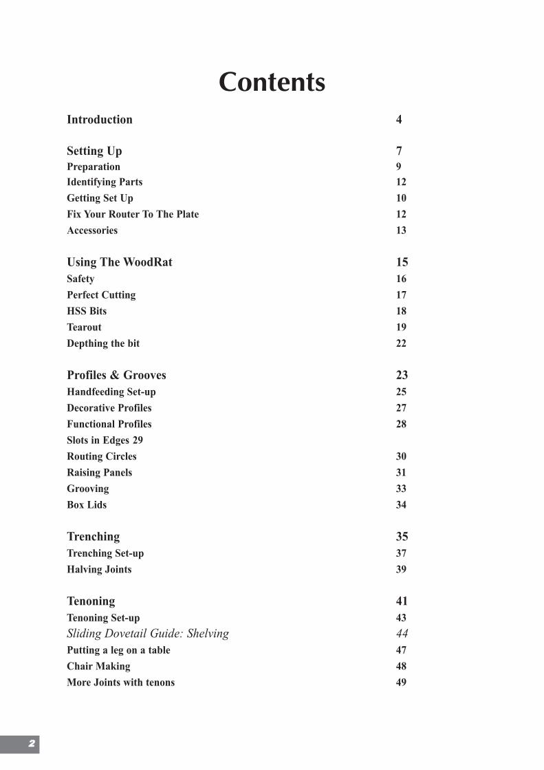
ContentsIntroduction 4
Setting Up 7Preparation 9Identifying Parts 12
Getting Set Up 10
Fix Your Router To The Plate 12
Accessories 13
Using The WoodRat 15Safety 16
Perfect Cutting 17
HSS Bits 18
Tearout 19
Depthing the bit 22
Profiles & Grooves 23Handfeeding Set-up 25
Decorative Profiles 27
Functional Profiles 28
Slots in Edges 29
Routing Circles 30
Raising Panels 31
Grooving 33
Box Lids 34
Trenching 35Trenching Set-up 37
Halving Joints 39
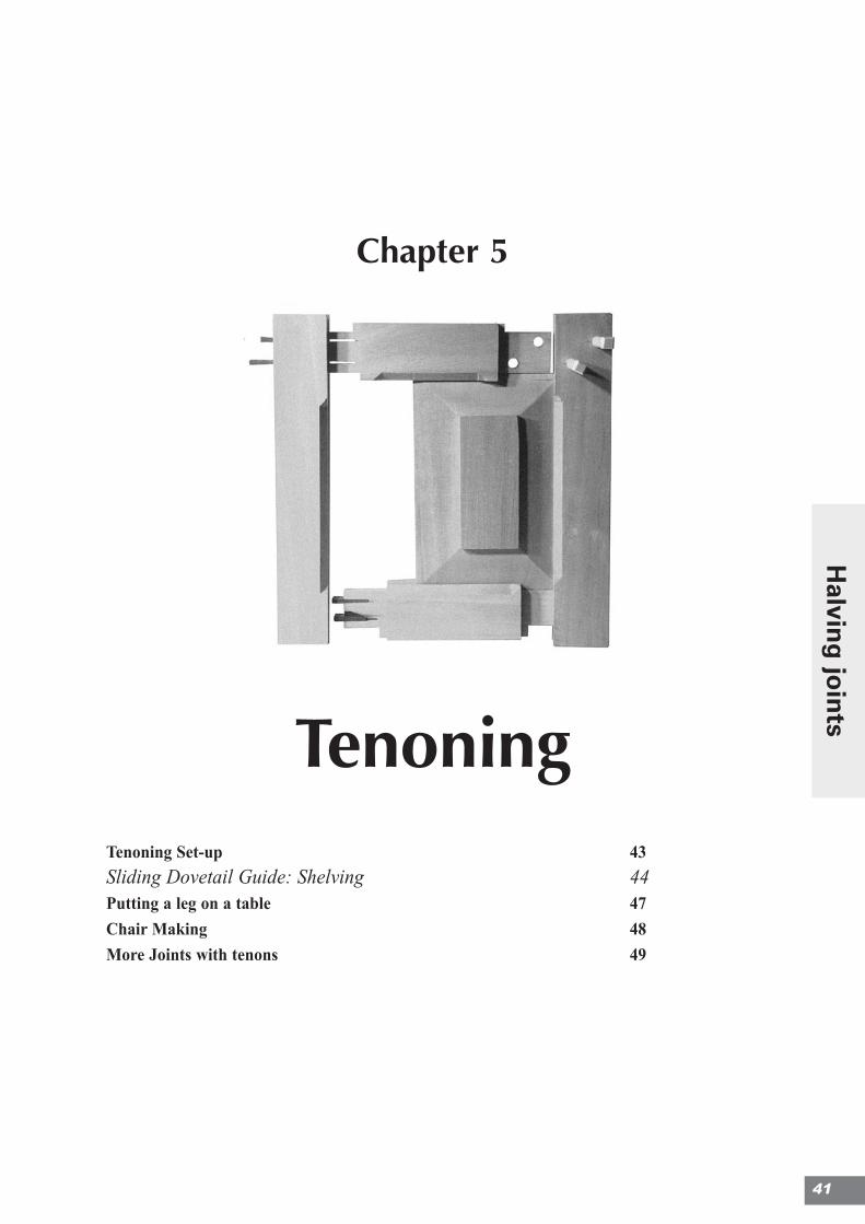
Tenoning 41Tenoning Set-up 43
Sliding Dovetail Guide: Shelving 44Putting a leg on a table 47
Chair Making 48
More Joints with tenons 49
22
3
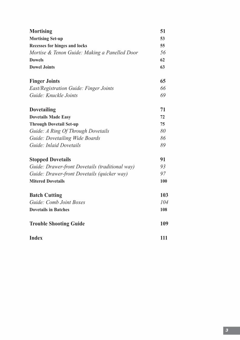
Mortising 51Mortising Set-up 53
Recesses for hinges and locks 55
Mortise & Tenon Guide: Making a Panelled Door 56Dowels 62
Dowel Joints 63
Finger Joints 65East/Registration Guide: Finger Joints 66Guide: Knuckle Joints 69
Dovetailing 71Dovetails Made Easy 72
Through Dovetail Set-up 75
Guide: A Ring Of Through Dovetails 80Guide: Dovetailing Wide Boards 86Guide: Inlaid Dovetails 89
Stopped Dovetails 91Guide: Drawer-front Dovetails (traditional way) 93Guide: Drawer-front Dovetails (quicker way) 97Mitered Dovetails 100
Batch Cutting 103Guide: Comb Joint Boxes 104Dovetails in Batches 108
Trouble Shooting Guide 109
Index 111
Welcome to WoodRatIntroduction
Fast, accurate and powerful, the router is an amazingly versatile tool. On its own,however, the router is not an easy tool to use. Three things are essential or it getsdangerous: the router itself has to be firmly held: the timber it's cutting has to be firmlyheld under it, and the bit has to travel in the correct direction through the wood.
Thus working with the router invloves making numerous jigs to secure the router'sposition to enable fine work to be done. Jig-making therefore takes over from the realwork in hand and becomes an end in itself. The purpose of the WoodRat is to hold theWood, and hold the router, replacing that multitude of jigs, and to allow the router to beput into the wood in the correct direction. It guides the router as it slides forwards andback, cutting the wood which is held firmly beneath it. It can also secure the router inthe manner of a router-table, so that the wood can be fed into the Bit. Work can be fedeither by hand or mechanically, held in the machine, in a way which is, in effect, power-fed.
Moreover, you can see the bit as it cuts, and work to a line. The timber movement isfinely controlled as it’s tracked into the bit. Within the useful limits, any size of boardcan be held at virtually any angle and orientation and be cut, profiled, mortised,dovetailed, slotted or grooved.
Because of this there is hardly a joint in the book that cannot be made by the WoodRat,either wholly or in part, with gains in both accuracy and speed.
The delight of working with the WoodRat comes not specially from the complicatedthings that it can do, but from the way it can do simple, everyday things like dovetaileddrawers and panelled doors and do them fast and well.
Generally, simple woodworking methods are used, like pencil lines drawn out on paperlabels or on the machine itself, and most of the jigs used to extend the WoodRat's rangeare extremely simple. As far as possible there are no add-ons to buy. The machine'scapabilities can be extended by very simple means that you can make up yourself.
The WoodRat comes into its own after the workpiece has been thicknessed and cut tolength. Although it will profile like an ordinary router table, its main job is to speed andimprove the jointing process. Jointing takes less time, saving money and giving acompetitive edge to the commercial workshop. The joints will fit exactly and thereforemore strongly. It follows that the timber used can be of lighter section. The techniquestend to be traditional cabinet making methods suited to the use of real wood. Thismeans that the construction can be lightweight and elegant. There is nothing difficultabout the way that the WoodRat works. As one WoodRat user put it… ‘After an hourof head-scratching, light dawns and it is all quite obvious’.
This book explores some of the countless possibilities brought about by what is a newapproach to cabinet-making. I hope that you have a very enjoyable time working withit, and if your livelihood depends on making furniture, that it will make a significantimpact on your profitability.
Happy ‘Ratting
Martin Godfrey
44
About This Book
If you’re new to woodworking as well as to the WoodRat this book may seem a bitdaunting. We recommend that you start simple at first and develop your skills as yourconfidence increases. Finger Joints, Profiles and Housing Joints are all good places tostart once you’ve set up.
The WoodRat is one of the safest ways of routing, but please read the section on safetybefore you begin work.
Language
This manual has been written partly in British English and partly in AmericanEnglish.Thus you may find varations in spelling of certain words, ie cutter/bit,center/center, vice/vise etc. In britain it is common to talk od “fixing” to mean“securing” though we’ve tried taken out this word wherever we found it. What reallymatters is that the meaning is absolutely clear to all, so do let us know if it isn’t.
Updates
This manual is updated periodically and the latest addendums and techniques can bedownloaded from our web site. To receive updates by email, send a blank email [email protected].
WoodRat Online
The WoodRat website is a good place to get up-to-date information about our productsand you can even buy them online, wherever you are in the World. It also links to theWoodRat Forum, where you can share your experiences with other WoodRat users. Welook forward to meeting you online.
Contacting Us
WoodRat, Fir Tree Barns, Godney, Wells, Somerset, BA5 1RZ, UK
UK Telephone: 0845 458 2033 Worldwide Telephone: +44 1458 832744
Support Email: [email protected]
Sales Email: [email protected] / [email protected]
Feedback on this manual: [email protected]
5

Notes
66
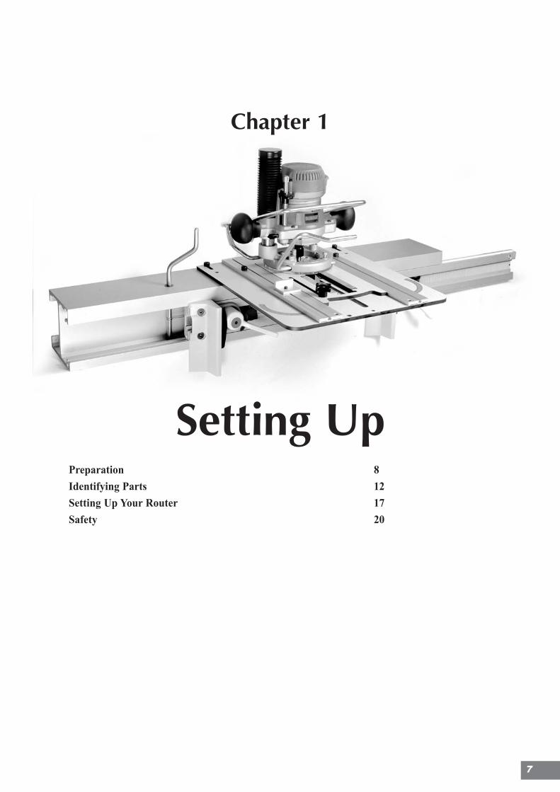
Chapter 1
Setting UpPreparation 8
Identifying Parts 12
Setting Up Your Router 17
Safety 20
7
.
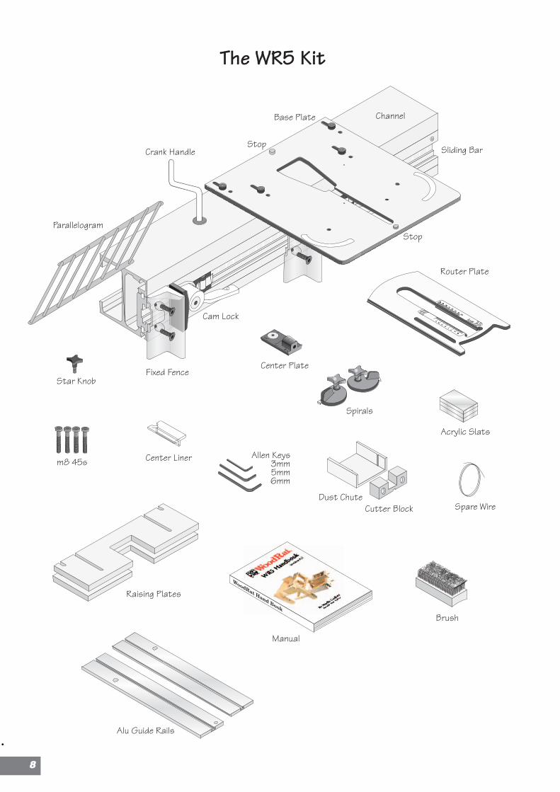
Center Linerm8 45s
Center Plate
Spirals
Allen Keys3mm5mm6mm
Acrylic Slats
Brush
Dust ChuteCutter Block Spare Wire
Manual
The WR5 Kit
Raising Plates
Sliding BarCrank Handle
Parallelogram
Fixed Fence
Cam Lock
Star Knob
Alu Guide Rails
Stop
ChannelBase Plate
Router Plate
Stop
88
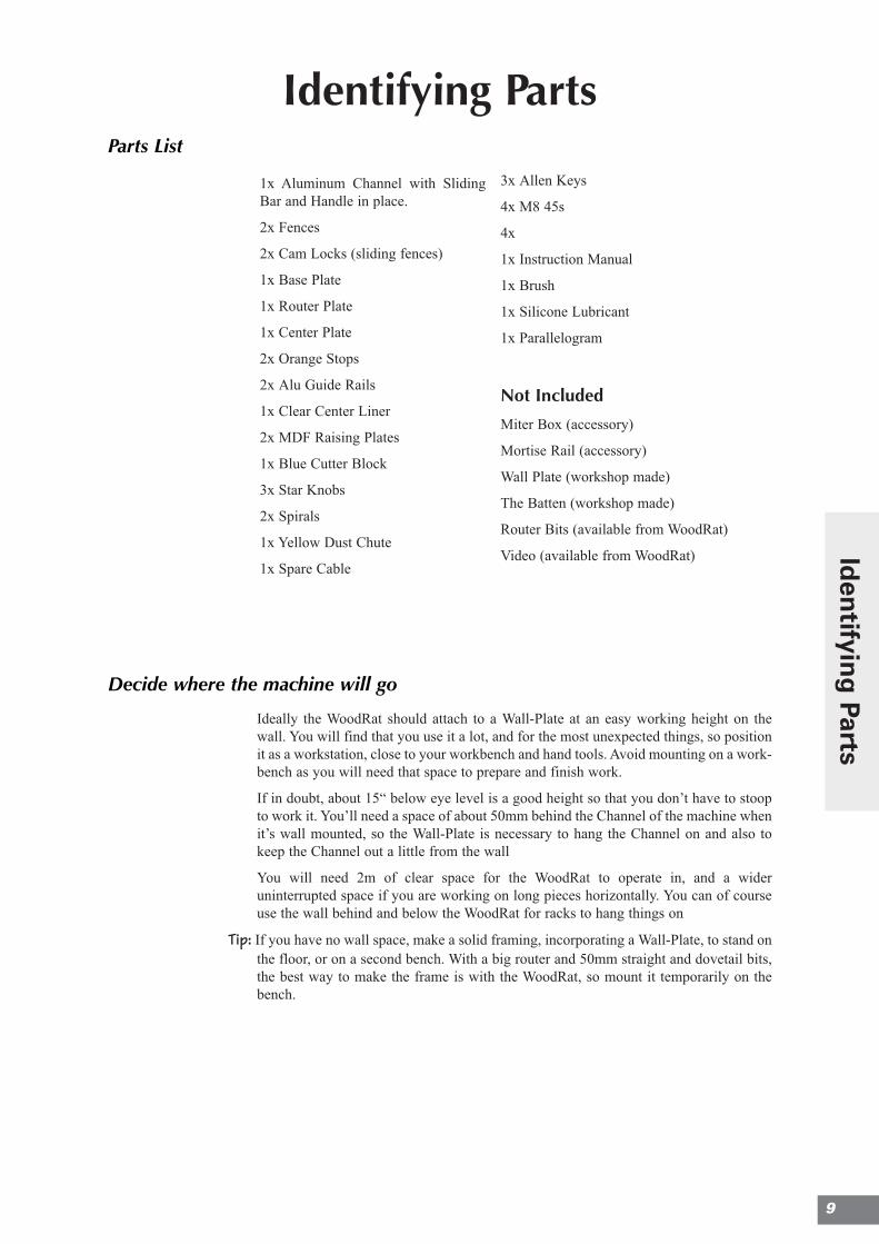
Identifying PartsParts List
3x Allen Keys
4x M8 45s
4x
1x Instruction Manual
1x Brush
1x Silicone Lubricant
1x Parallelogram
Not Included
Miter Box (accessory)
Mortise Rail (accessory)
Wall Plate (workshop made)
The Batten (workshop made)
Router Bits (available from WoodRat)
Video (available from WoodRat)
Decide where the machine will go
Ideally the WoodRat should attach to a Wall-Plate at an easy working height on thewall. You will find that you use it a lot, and for the most unexpected things, so positionit as a workstation, close to your workbench and hand tools. Avoid mounting on a work-bench as you will need that space to prepare and finish work.
If in doubt, about 15“ below eye level is a good height so that you don’t have to stoopto work it. You’ll need a space of about 50mm behind the Channel of the machine whenit’s wall mounted, so the Wall-Plate is necessary to hang the Channel on and also tokeep the Channel out a little from the wall
You will need 2m of clear space for the WoodRat to operate in, and a wideruninterrupted space if you are working on long pieces horizontally. You can of courseuse the wall behind and below the WoodRat for racks to hang things on
Tip: If you have no wall space, make a solid framing, incorporating a Wall-Plate, to stand onthe floor, or on a second bench. With a big router and 50mm straight and dovetail bits,the best way to make the frame is with the WoodRat, so mount it temporarily on thebench.
1x Aluminum Channel with SlidingBar and Handle in place.
2x Fences
2x Cam Locks (sliding fences)
1x Base Plate
1x Router Plate
1x Center Plate
2x Orange Stops
2x Alu Guide Rails
1x Clear Center Liner
2x MDF Raising Plates
1x Blue Cutter Block
3x Star Knobs
2x Spirals
1x Yellow Dust Chute
1x Spare Cable
9
Iden
tifying
Parts
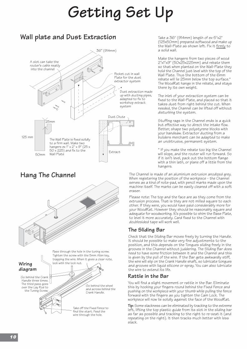
Getting Set UpWall plate and Dust Extraction
Hang The Channel
36” (914mm)
The Wall Plate is fixed solidlyto a firm wall. Make twohangers ex 1" x 2" x 9" (25 x50 x 225) and fix to theWall Plate
A slot can take therouter’s cable neatly into the channel
Dust extraction madeup with ducting pipes,adapted to fix toworkshop extractsystem
50mm
125 mm
25mmDust Chute
Extract
Pocket cut in wallPlate for the dustextractor system
Take off the Fixed Fence tofind the start. Feed thewire through the hole.
Go behind the wheeland across behind theCrank Handle.
Go behind the CrankHandle three times.The third pass goesover the Lay Rod to
the Tuning Screw.
Pass through the hole in the tuning screw.Tighten the screw with the 5mm Allen key,trapping the wire. When it gives a clear note,lock with the lock nut.Wiring
diagram
Take a 36" (914mm) length of ex-5"x2"(125x50mm) prepared softwood and make upthe Wall-Plate as shown left. Fix it firmly toa solid wall.
Make the hangers from two pieces of wood2"x1"x9" (50x25x225mm) and rebate themso that when planted on the Wall-Plate theyhold the Channel just level with the top of theWall Plate. Thus the bottom of the 6mmrebate will lie 25mm below the top surface.*The WoodRat hangs in the rebate, and staysthere by its own weight.
The inlet of your extraction system can befixed to the Wall-Plate, and placed so that ittakes dust from right behind the cut. Whenneeded, the Channel can be lifted off withoutdisturbing the system.
Stuffing rags in the Channel ends is a quickbut effective way to direct the intake flow.Better, shape two polystyrene blocks withyour bandsaw. Extractor ducting from abuilders merchant can be adapted to makean unobtrusive, permanent system.
* If you make the rebate too big the Channelwill slope, and the router will run forward. Soif it isn’t level, pack out the bottom flangewith a thin lath, or plane off a little from thehangers.
The Channel is made of an aluminium extrusion anodized grey.When registering the position of the workpiece - the Channelserves as a kind of note-pad, with pencil marks made upon themachine itself. The marks can be easily cleaned off with a softeraser.Please note: The top and the face are as they come from theextrusion process. That is they are not milled square to eachother. If they were, you would have paid considerably more foryour WoodRat. However they should be reasonably square andadequate for woodworking. It’s possible to shim the Base Plate,to level it more accurately. Card fixed to the Channel withdoublesided tape will work well.
The Sliding BarCheck that the Sliding Bar moves freely by turning the Handle.It should be possible to make very fine adjustments to theposition, and this depends on the Tongues sliding freely in thegrooves in the Channel without juddering. The Sliding Bar doesneed to have some friction between it and the Channel and thisis given by the pull of the wire. If the Bar gets awkwardly stiff,the wire will slip on the Crank Handle shaft, so lubricate tonguesand grooves with liquid silicone or spray. You can also lubricatethe wire to extend its life.
Rattle in the BarYou will find a slight movement or rattle in the Bar. Eliminatethis by hooking your fingers round behind the Fixed Fence andpushing on the workpiece with your thumb while pulling the fenceforward with the fingers as you tighten the Cam Lock. Theworkpiece will now lie solidly against the face of the WoodRat.Tip: Some slackness can be eliminated by tracking to the extremeleft, lifting the top plastic guide from its slot in the sliding baras far as possible and tracking to the right to re-seat it (andrepeating on the right). It then tracks much better with lessslack.
1100
4M
2130
2120
21342124 Cam
21254M
2136
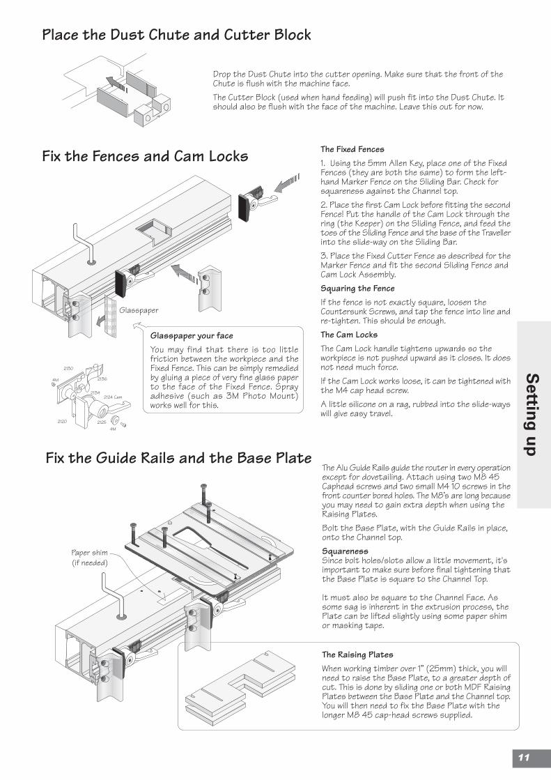
Place the Dust Chute and Cutter Block
Fix the Fences and Cam Locks
Fix the Guide Rails and the Base Plate
The Fixed Fences1. Using the 5mm Allen Key, place one of the FixedFences (they are both the same) to form the left-hand Marker Fence on the Sliding Bar. Check forsquareness against the Channel top.2. Place the first Cam Lock before fitting the secondFence! Put the handle of the Cam Lock through thering (the Keeper) on the Sliding Fence, and feed thetoes of the Sliding Fence and the base of the Travellerinto the slide-way on the Sliding Bar.3. Place the Fixed Cutter Fence as described for theMarker Fence and fit the second Sliding Fence andCam Lock Assembly.Squaring the FenceIf the fence is not exactly square, loosen theCountersunk Screws, and tap the fence into line andre-tighten. This should be enough.The Cam LocksThe Cam Lock handle tightens upwards so theworkpiece is not pushed upward as it closes. It doesnot need much force.If the Cam Lock works loose, it can be tightened withthe M4 cap head screw.A little silicone on a rag, rubbed into the slide-wayswill give easy travel.
Drop the Dust Chute into the cutter opening. Make sure that the front of theChute is flush with the machine face.The Cutter Block (used when hand feeding) will push fit into the Dust Chute. Itshould also be flush with the face of the machine. Leave this out for now.
The Alu Guide Rails guide the router in every operationexcept for dovetailing. Attach using two M8 45Caphead screws and two small M4 10 screws in thefront counter bored holes. The M8’s are long becauseyou may need to gain extra depth when using theRaising Plates.Bolt the Base Plate, with the Guide Rails in place,onto the Channel top.SquarenessSince bolt holes/slots allow a little movement, it'simportant to make sure before final tightening thatthe Base Plate is square to the Channel Top.
It must also be square to the Channel Face. Assome sag is inherent in the extrusion process, thePlate can be lifted slightly using some paper shimor masking tape.
Glasspaper
Glasspaper your faceYou may find that there is too littlefriction between the workpiece and theFixed Fence. This can be simply remediedby gluing a piece of very fine glass paperto the face of the Fixed Fence. Sprayadhesive (such as 3M Photo Mount)works well for this.
The Raising PlatesWhen working timber over 1” (25mm) thick, you willneed to raise the Base Plate, to a greater depth ofcut. This is done by sliding one or both MDF RaisingPlates between the Base Plate and the Channel top.You will then need to fix the Base Plate with thelonger M8 45 cap-head screws supplied.
Paper shim(if needed)
11
Settin
g u
p
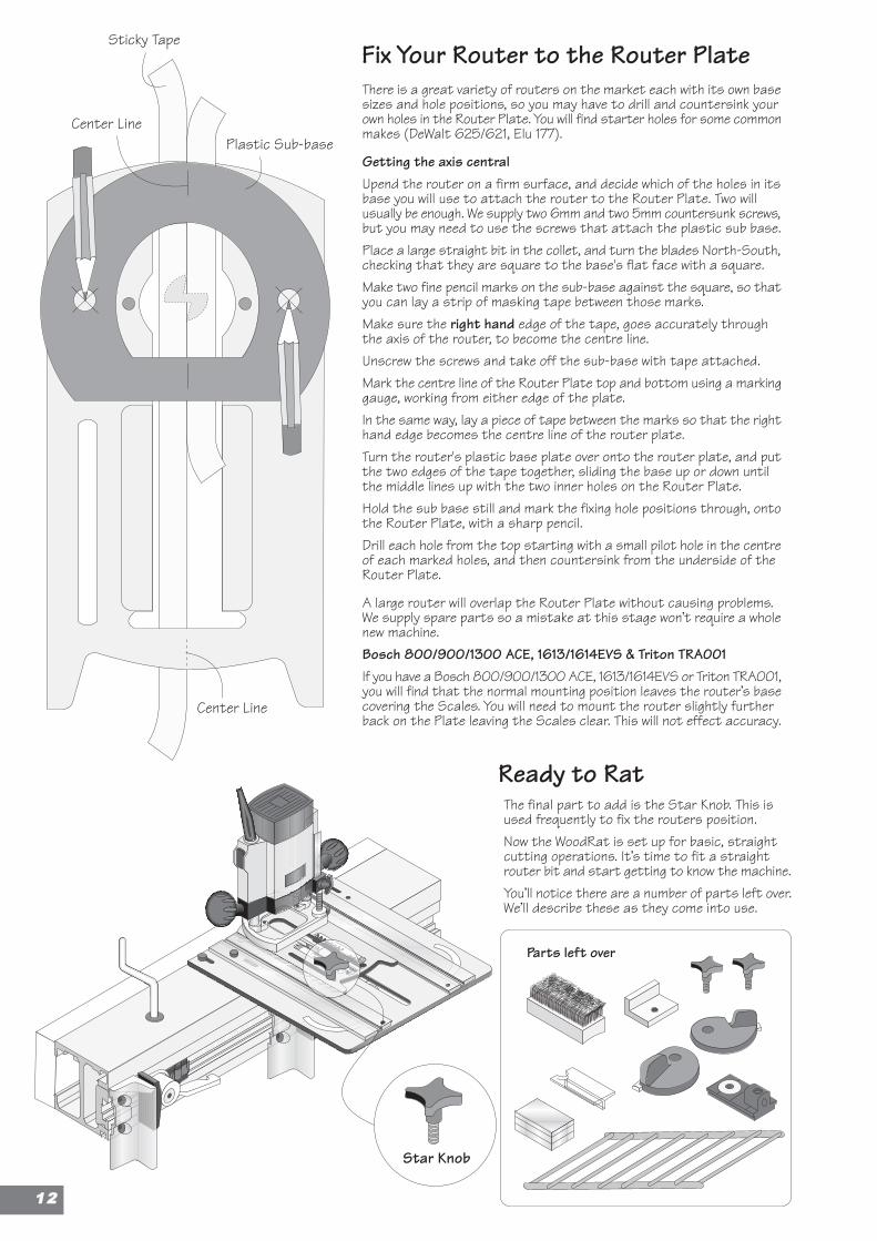
Fix Your Router to the Router PlateThere is a great variety of routers on the market each with its own basesizes and hole positions, so you may have to drill and countersink yourown holes in the Router Plate. You will find starter holes for some commonmakes (DeWalt 625/621, Elu 177).
Getting the axis centralUpend the router on a firm surface, and decide which of the holes in itsbase you will use to attach the router to the Router Plate. Two willusually be enough. We supply two 6mm and two 5mm countersunk screws,but you may need to use the screws that attach the plastic sub base.Place a large straight bit in the collet, and turn the blades North-South,checking that they are square to the base's flat face with a square.Make two fine pencil marks on the sub-base against the square, so thatyou can lay a strip of masking tape between those marks.Make sure the right hand edge of the tape, goes accurately throughthe axis of the router, to become the centre line.Unscrew the screws and take off the sub-base with tape attached.Mark the centre line of the Router Plate top and bottom using a markinggauge, working from either edge of the plate.In the same way, lay a piece of tape between the marks so that the righthand edge becomes the centre line of the router plate.Turn the router's plastic base plate over onto the router plate, and putthe two edges of the tape together, sliding the base up or down untilthe middle lines up with the two inner holes on the Router Plate.Hold the sub base still and mark the fixing hole positions through, ontothe Router Plate, with a sharp pencil.Drill each hole from the top starting with a small pilot hole in the centreof each marked holes, and then countersink from the underside of theRouter Plate.
A large router will overlap the Router Plate without causing problems.We supply spare parts so a mistake at this stage won’t require a wholenew machine.Bosch 800/900/1300 ACE, 1613/1614EVS & Triton TRA001If you have a Bosch 800/900/1300 ACE, 1613/1614EVS or Triton TRA001,you will find that the normal mounting position leaves the router’s basecovering the Scales. You will need to mount the router slightly furtherback on the Plate leaving the Scales clear. This will not effect accuracy.
Sticky Tape
Plastic Sub-base
Center Line
Ready to Rat
Parts left over
Star Knob
The final part to add is the Star Knob. This isused frequently to fix the routers position.Now the WoodRat is set up for basic, straightcutting operations. It’s time to fit a straightrouter bit and start getting to know the machine.You’ll notice there are a number of parts left over.We’ll describe these as they come into use.
Center Line
1122
Accessories
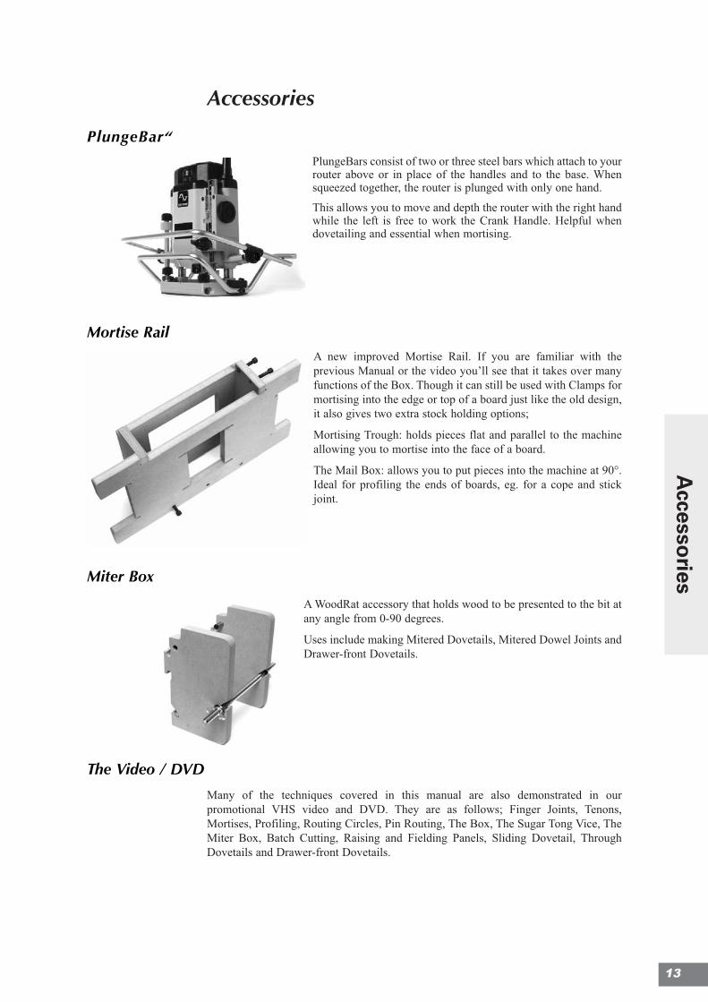
PlungeBar“
PlungeBars consist of two or three steel bars which attach to yourrouter above or in place of the handles and to the base. Whensqueezed together, the router is plunged with only one hand.
This allows you to move and depth the router with the right handwhile the left is free to work the Crank Handle. Helpful whendovetailing and essential when mortising.
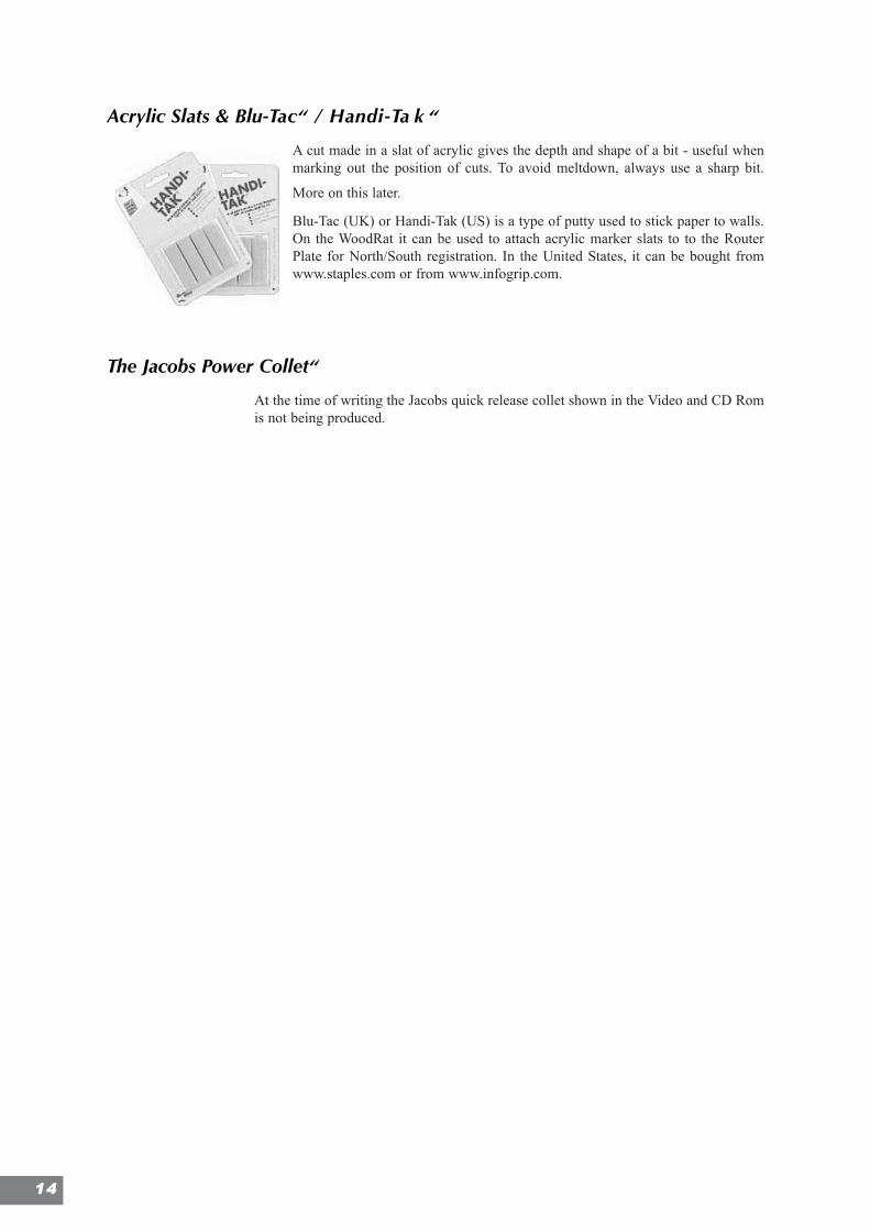
Mortise RailA new improved Mortise Rail. If you are familiar with theprevious Manual or the video you’ll see that it takes over manyfunctions of the Box. Though it can still be used with Clamps formortising into the edge or top of a board just like the old design,it also gives two extra stock holding options;
Mortising Trough: holds pieces flat and parallel to the machineallowing you to mortise into the face of a board.
The Mail Box: allows you to put pieces into the machine at 90°.Ideal for profiling the ends of boards, eg. for a cope and stickjoint.
Miter Box
A WoodRat accessory that holds wood to be presented to the bit atany angle from 0-90 degrees.
Uses include making Mitered Dovetails, Mitered Dowel Joints andDrawer-front Dovetails.
The Video / DVD
Many of the techniques covered in this manual are also demonstrated in ourpromotional VHS video and DVD. They are as follows; Finger Joints, Tenons,Mortises, Profiling, Routing Circles, Pin Routing, The Box, The Sugar Tong Vice, TheMiter Box, Batch Cutting, Raising and Fielding Panels, Sliding Dovetail, ThroughDovetails and Drawer-front Dovetails.
13
Accesso
ries
Acrylic Slats & Blu-Tac“ / Handi-Ta k “
A cut made in a slat of acrylic gives the depth and shape of a bit - useful whenmarking out the position of cuts. To avoid meltdown, always use a sharp bit.
Blu-Tac (UK) or Handi-Tak (US) is a type of putty used to stick paper to walls.On the WoodRat it can be used to attach acrylic marker slats to to the RouterPlate for North/South registration. In the United States, it can be bought fromwww.staples.com or from www.infogrip.com.
The Jacobs Power Collet“
At the time of writing the Jacobs quick release collet shown in the Video and CD Romis not being produced.
1144
Chapter 2
Using the WoodRatSafety 16
Perfect Cutting 17
HSS Bits 18
Tearout 19
Depthing the bit 22
15
1166
SafetyThis manual assumes that you are familiar with using your router and have read theinstructions that came with it.
General• Wear Safety Goggles and do not look beneath the Plate when making a cut.
• Arrange a vacuum dust extraction system to take the harmful, fine dust from behindthe cut. Or wear a dust mask
• Do not use a router when tired or under medication that may cause drowsiness.
• Disconnect router from mains supply when changing bits.
• Use either the Guide Rails or the Center Plate and Spirals, or both, but neverneither. The Router Plate must be held in one of these ways.
Hand-feeding
There are special requirements for Profiling, Grooving & Rebating. Read the relevantsection before you try them.• When passing work through by hand always use the Cutter Block in position.
• Always check that the Router Plate is screwed securely to the Base Plate with theStar Knob.
• Do not attempt to hand feed small or awkward pieces. Devise a carriage that canbe held in one or both Cam Locks and track it through the bit.
• Always enter the wood into the router bit in the correct direction. That is against thebit blade rotation, as explained in the text.
• When holding a piece and feeding it through the bit, never hold it in such a way thatif the piece were to be whisked away by the bit the hands would be exposed to thebit. This could happen if you get the direction wrong.
Grooving• Having made one grooving cut down a length, be extremely careful if you are widen-
ing the groove. The next cut must be an up-cut, ie. against the bit blade. The bit goesclockwise, and the direction of the pass will depend on which side of the trench isbeing widened.
Mortising• Take special care when plunging into the work when drilling holes and making mor-
tises. Ensure that the work is very firmly secured in the Cam Locks, and proceedslowly with a sharp bit with good end cutting ability.
Using Wide Bits:
Do not use bits of more than 13mm, (1/2”) diameter for cutting long housings as you willendanger the long slot in the Base Plate! If you want to make long cross-cuts with big bitsorder a second Base Plate from your WoodRat supplier and modify it.
Perfect Cutting
Introducing High-Speed Steel
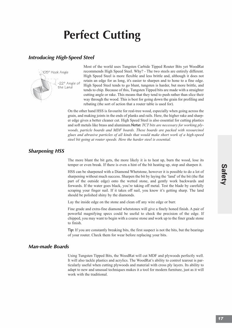
Most of the world uses Tungsten Carbide Tipped Router Bits yet WoodRatrecommends High Speed Steel. Why? - The two steels are entirely different.High Speed Steel is more flexible and less brittle and, although it does notretain an edge for as long, it's easier to sharpen and to hone to a fine edge.High Speed Steel tends to go blunt, tungsten is harder, but more brittle, andtends to chip. Because of this, Tungsten Tipped bits are made with a straightercutting angle or rake. This means that they tend to push rather than slice theirway through the wood. This is best for going down the grain for profiling andrebating (the sort of action that a router table is used for).
On the other hand HSS is favourite for real-tree wood, especially when going across thegrain, and making joints in the ends of planks and rails. Here, the higher rake and sharp-er edge gives a better cleaner cut. High Speed Steel is also essential for cutting plasticsand soft metals like brass and aluminum.Note: TCT bits are necessary for working ply-woods, particle boards and MDF boards. These boards are packed with resourcinolglues and abrasive particles of all kinds that would make short work of a high-speedsteel bit going at router speeds. Here the harder steel is essential.
Sharpening HSS
The more blunt the bit gets, the more likely it is to heat up, burn the wood, lose itstemper or even break. If there is even a hint of the bit heating up, stop and sharpen it.
HSS can be sharpened with a Diamond Whetstone, however it is possible to do a lot ofsharpening without much success. Sharpen the bit by laying the ‘land’ of the bit (the flatpart of the outside edge) onto the wetted stone, and gently work backwards andforwards. If the water goes black, you’re taking off metal. Test the blade by carefullyscraping your finger nail. If it takes off nail, you know it’s getting sharp. The landshould be polished shiny by the diamonds.
Lay the inside edge on the stone and clean off any wire edge or burr.
Fine grade and extra-fine diamond whetstones will give a finely honed finish. A pair ofpowerful magnifying specs could be useful to check the precision of the edge. Ifchipped, you may want to begin with a coarse stone and work up to the finer grade stoneto finish.
Tip: If you are constantly breaking bits, the first suspect is not the bits, but the bearingsof your router. Check them for wear before replacing your bits.
Man-made Boards
Using Tungsten Tipped Bits, the WoodRat will cut MDF and plywoods perfectly well.It will also tackle plastics and acrylics. The WoodRat’s ability to control tearout is par-ticularly useful when cutting plywoods and material with cross ply layers. Its ability toadapt to new and unusual techniques makes it a tool for modern furniture, just as it willwork with the traditional.
105º Hook Angle
-22º Angle ofthe Land
17
Safety
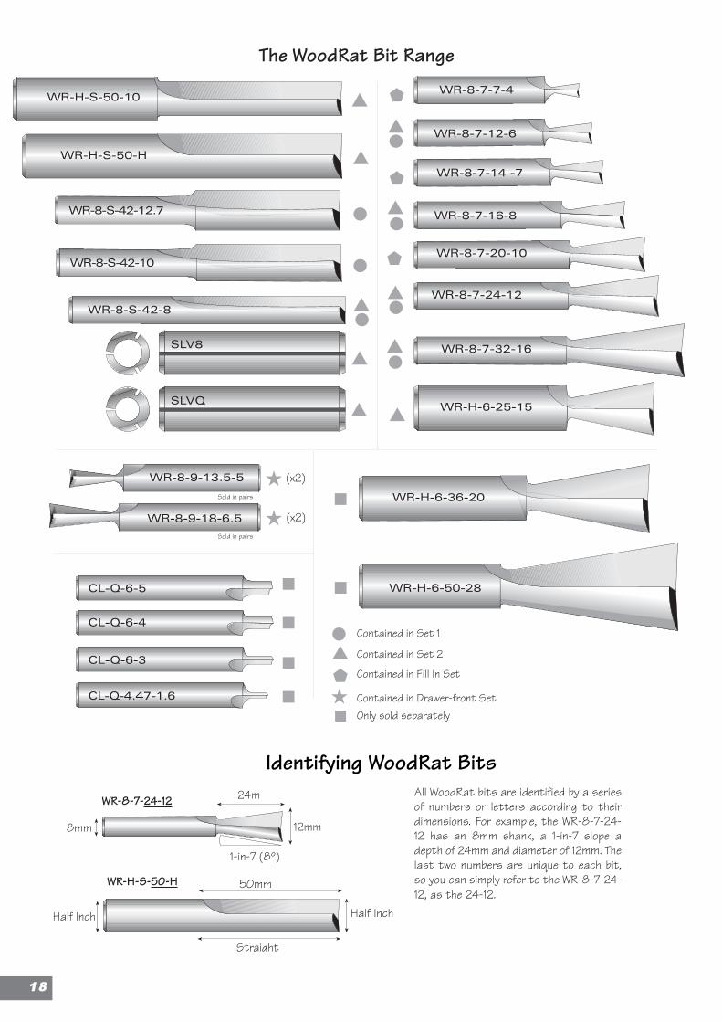
Identifying WoodRat BitsAll WoodRat bits are identified by a seriesof numbers or letters according to theirdimensions. For example, the WR-8-7-24-12 has an 8mm shank, a 1-in-7 slope adepth of 24mm and diameter of 12mm. Thelast two numbers are unique to each bit,so you can simply refer to the WR-8-7-24-12, as the 24-12.
WR-H-S-50-H
WR-8-7-24-12
Half Inch
8mm
1-in-7 (8º)
12mm
Half Inch
50mm
24m
Straight
SLVQ
SLV8
The WoodRat Bit Range
WR-8-7-7-4
WR-8-7-12-6
WR-8-7-14 -7
WR-8-7-16-8
WR-8-7-20-10
WR-8-7-24-12
WR-8-7-32-16
WR-H-S-50-H
WR-8-S-42-12.7
WR-8-S-42-8
WR-8-S-42-10
WR-8-9-13.5-5
WR-8-9-18-6.5
WR-H-6-25-15
WR-H-6-50-28
WR-H-6-36-20
CL-Q-6-5
CL-Q-6-4
CL-Q-6-3
CL-Q-4.47-1.6
105° Hook angle
-22° Angleof the land
WR-H-S-50-10
Contained in Set 1
Contained in Set 2
Contained in Fill In Set
Contained in Drawer-front SetOnly sold separately
(x2)
(x2)Sold in pairs
Sold in pairs
1188
19
Perfect Cu
tting
Eliminating Tear out
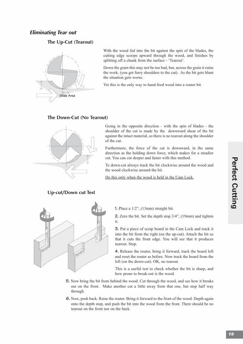
The Up-Cut (Tearout)
With the wood fed into the bit against the spin of the blades, thecutting edge scoops upward through the wood, and finishes bysplitting off a chunk from the surface - ‘Tearout’.
Down the grain this may not be too bad, but, across the grain it ruinsthe work, (you get furry shoulders to the cut). As the bit gets bluntthe situation gets worse.
Yet this is the only way to hand-feed wood into a router bit.
The Down-Cut (No Tearout)
Going in the opposite direction - with the spin of blades - theshoulder of the cut is made by the downward shear of the bitagainst the intact material, so there is no tearout along the shoulderof the cut.
Furthermore, the force of the cut is downward, in the samedirection as the holding down force, which makes for a steadiercut. You can cut deeper and faster with this method.
To down-cut always track the bit clockwise around the wood andthe wood clockwise around the bit.
Do this only when the wood is held in the Cam Lock.
Up-cut/Down cut Test
1. Place a 1/2”, (13mm) straight bit.
2. Zero the bit. Set the depth stop 3/4”, (19mm) and tightenit.
3. Put a piece of scrap board in the Cam Lock and track itinto the bit from the right (on the up-cut). Attach the bit sothat it cuts the front edge. You will see that it producestearout. Stop.
4. Release the router, bring it forward, track the board leftand reset the router as before. Now track the board from theleft (on the down-cut). OK, no tearout.
This is a useful test to check whether the bit is sharp, andhow prone to break-out is the wood.
5. Now bring the bit from behind the wood. Cut through the wood, and see how it breaksout on the front. Make another cut a little away from that one, but stop half waythrough.
6. Now, push back. Raise the router. Bring it forward to the front of the wood. Depth againonto the depth stop, and push the bit into the wood from the front. There should be notearout on the front nor on the back.
Glide Area
Glide Area
More Ways to Beat TearoutThroughout this manual we stress the need to enter the wood into the blade in the rightdirection, but the following points should also be borne in mind.
• Enter the bit into the wood slowly and exit carefully. Where possible make a rough cuta little away from the line and then make a fine cut exactly on the line.
• Stack the two outside faces of the Sides together inside when cutting dovetail socketsso that when put outside again there is no tearout showing. In fact the tails do not breakout much as the cut is an upward spiralling action due to the cone shape of the bit.
Most tearout occurs in soft woods like pine, and mostly when using the straight bit.Scribing the shoulder line makes it worse. Taping it is time consuming. Putting blocksagainst the bit as it comes through is unpredictable but . . .
Pre-cutting
There is a simple alternative to all these. You can pre-cut the front of the board as yougo, making a cut at each joint position. Then you cut the joint from behind the board inthe usual way. Since there is nothing on the front face to break out, the joint is perfectlyclean. By this means you can eliminate break-out in virtually every situation.
Mowing a Board End Square
One of the simplest, but most useful, tasks is to clean off theend of a board, square and tearout free. The surface tends tolook like a mown lawn, but this can be finished cleanly with asharp plane.
If a stack of pieces are clamped together and “mown” flat witha sharp bit, they will all be exactly the same size square andtrue. They are then ready to be lifted up under the Base Plateand all cut together.
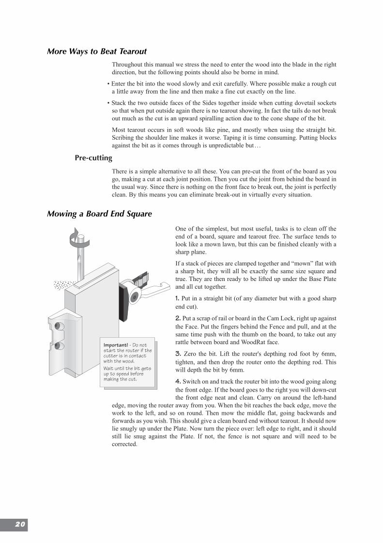
1. Put in a straight bit (of any diameter but with a good sharpend cut).
2. Put a scrap of rail or board in the Cam Lock, right up againstthe Face. Put the fingers behind the Fence and pull, and at thesame time push with the thumb on the board, to take out anyrattle between board and WoodRat face.
3. Zero the bit. Lift the router's depthing rod foot by 6mm,tighten, and then drop the router onto the depthing rod. Thiswill depth the bit by 6mm.
4. Switch on and track the router bit into the wood going alongthe front edge. If the board goes to the right you will down-cutthe front edge neat and clean. Carry on around the left-hand
edge, moving the router away from you. When the bit reaches the back edge, move thework to the left, and so on round. Then mow the middle flat, going backwards andforwards as you wish. This should give a clean board end without tearout. It should nowlie snugly up under the Plate. Now turn the piece over: left edge to right, and it shouldstill lie snug against the Plate. If not, the fence is not square and will need to becorrected.
Important! - Do notstart the router if thecutter is in contactwith the wood.Wait until the bit getsup to speed beforemaking the cut.
2200
Dealing with Bowed Boards
The WoodRat has the advantage that the work can be prepared and quickly jointedbefore it has had time to move. The structure of the furniture, if it is well designed, willkeep the workpiece straight. That’s the theory.
In practice, it is possible to take out the bow in a plank with the thumb of the left handpushing the center of the board onto the Bar. If it is not possible to take the bow outwith the fingers, then it could be argued that such a board needs planing flat anyway.The fingers are placed behind the Fence, pulling on the Fence and Sliding Bar, and thethumb keeps the wood flat. Check that your thumb is well clear of the bit.
Tip: This is also a useful place for the thumb when cutting good boards as you can checkthat all is secure and the bit has not pulled the board forward.
If the board is concave, lock the edge in place tight and flat at the right-hand, slidingfence edge, and then push the left-hand edge flat. The Bar might need assistance tomove it, but the board should go dead flat.
It is also possible to flatten a board by putting two battens across it, and clamping themtogether to flatten the board, before locking it in place.
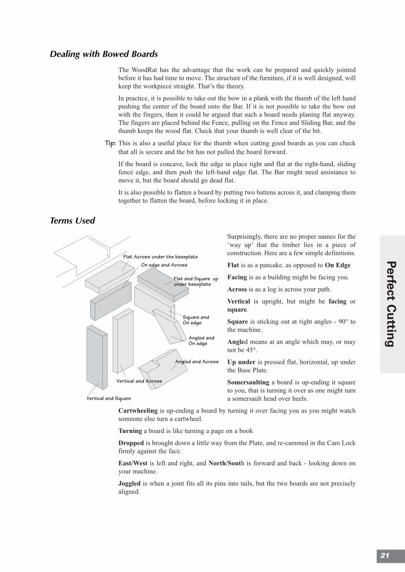
Terms Used
Surprisingly, there are no proper names for the‘way up’ that the timber lies in a piece ofconstruction. Here are a few simple definitions.
Flat is as a pancake. as opposed to On Edge
Facing is as a building might be facing you.
Across is as a log is across your path.
Vertical is upright, but might be facing orsquare.
Square is sticking out at right angles - 90° tothe machine.
Angled means at an angle which may, or maynot be 45°.
Up under is pressed flat, horizontal, up underthe Base Plate.
Somersaulting a board is up-ending it squareto you, that is turning it over as one might turna somersault head over heels.
Cartwheeling is up-ending a board by turning it over facing you as you might watchsomeone else turn a cartwheel.
Turning a board is like turning a page on a book
Dropped is brought down a little way from the Plate, and re-cammed in the Cam Lockfirmly against the face.
East/West is left and right, and North/South is forward and back - looking down onyour machine.
Joggled is when a joint fits all its pins into tails, but the two boards are not preciselyaligned.
Flat Across under the baseplateOn edge and Across
Flat and Square upunder baseplate
Square andOn edge
Vertical and Across
Vertical and Square
Angled and Across
Angled andOn edge
21
Perfect Cu
tting
2222
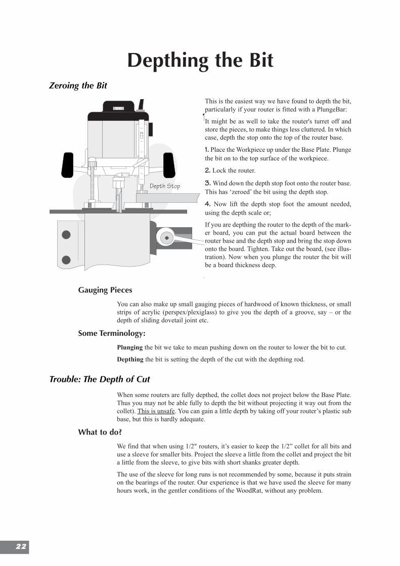
Depthing the BitZeroing the Bit
This is the easiest way we have found to depth the bit,particularly if your router is fitted with a PlungeBar:
It might be as well to take the router's turret off andstore the pieces, to make things less cluttered. In whichcase, depth the stop onto the top of the router base.
1. Place the Workpiece up under the Base Plate. Plungethe bit on to the top surface of the workpiece.
2. Lock the router.
3. Wind down the depth stop foot onto the router base.This has ‘zeroed’ the bit using the depth stop.
4. Now lift the depth stop foot the amount needed,using the depth scale or;
If you are depthing the router to the depth of the mark-er board, you can put the actual board between therouter base and the depth stop and bring the stop downonto the board. Tighten. Take out the board, (see illus-tration). Now when you plunge the router the bit willbe a board thickness deep.
Gauging Pieces
You can also make up small gauging pieces of hardwood of known thickness, or smallstrips of acrylic (perspex/plexiglass) to give you the depth of a groove, say – or thedepth of sliding dovetail joint etc.
Some Terminology:
Plunging the bit we take to mean pushing down on the router to lower the bit to cut.
Depthing the bit is setting the depth of the cut with the depthing rod.
Trouble: The Depth of Cut
When some routers are fully depthed, the collet does not project below the Base Plate.Thus you may not be able fully to depth the bit without projecting it way out from thecollet). This is unsafe. You can gain a little depth by taking off your router’s plastic subbase, but this is hardly adequate.
What to do?
We find that when using 1/2" routers, it’s easier to keep the 1/2” collet for all bits anduse a sleeve for smaller bits. Project the sleeve a little from the collet and project the bita little from the sleeve, to give bits with short shanks greater depth.
The use of the sleeve for long runs is not recommended by some, because it puts strainon the bearings of the router. Our experience is that we have used the sleeve for manyhours work, in the gentler conditions of the WoodRat, without any problem.
A
Finger JointsIntroductionWe have included this short section as a prelude to makingDovetails, as it provides a simple exercise in East/Westregistration, without needing to change cutters or reconfigurethe machine.Set upSet the machine for straight cutting with Guide Rails in place.Fit a 1/2’ Straight Cutter (WR-S-50-H).Prepare two boards of identical width and depth. For thepurpose of this exercise, you could mark one as board A andone as board B.
Depth Stop
(an introduction to East/West Registration)
Lock Board A in cutter position under theBase Plate.Plunge the cutter on to the top surface ofthe workpiece and lock the router.Wind down the depth stop foot onto therouter base. This has ‘zeroed’ the bit usingthe depth stop.Now lift the depth stop foot the amountneeded, using the depth scale or;as you are depthing the router to the depthof the marker board, you can put Board Bbetween the router base and the depth stopand bring the stop down onto the board.Tighten. Take out the board. Now when youplunge the router, the bit will be a boardthickness deep.
Track the piece left or rightand cut a socket in it -roughly in the middle.
1
2
Chapter 3
Profiles & Grooves
Handfeeding Set-up 25
Decorative Profiles 27
Functional Profiles 28
Slots in Edges 29
Routing Circles 30
Raising Panels 31
Grooving 33
Box Lids 34
Grooving 42
23
Dep
ting
Th
e Bit
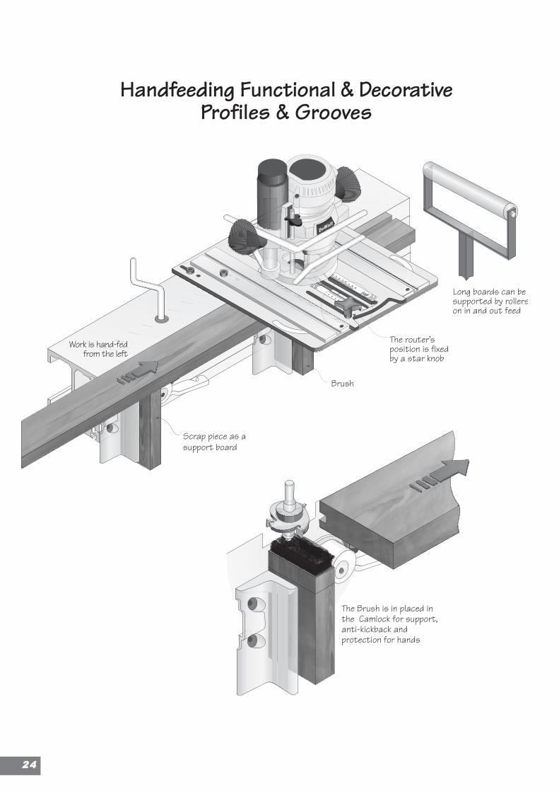
Handfeeding Functional & DecorativeProfiles & Grooves
The Brush is in placed inthe Camlock for support,anti-kickback andprotection for hands
The router’sposition is fixedby a star knob
Long boards can besupported by rollerson in and out feed
Scrap piece as asupport board
Work is hand-fedfrom the left
Brush
2244
Hand FeedingWhen the bit is depthed below the Plate, work can be passed through, just as one passeswork across a router table. The difference is that the router is the right way up so youcan get to the controls and depth the router easily. The depth of cut is constant as witha router table, but you can see the bit as it cuts, as with an overhead router, so you havethe best of both worlds.
Below the Plate, the bit is exposed, so it must be treated with respect. This is quite safeas long as some basic rules are carefully observed.
Set up For Hand Feeding
The Brush
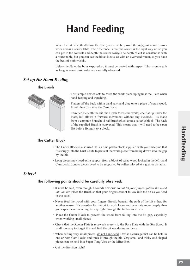
This simple device acts to force the work piece up against the Plate whenhand feeding and trenching..
Flatten off the back with a band saw, and glue onto a piece of scrap wood.It will then cam into the Cam Lock.
Cammed Beneath the bit, the Brush forces the workpiece flat up under thePlate, but allows it forward movement without any kickback. It’s madefrom a common household nail brush glued onto a suitable block. The backof the supplied Brush is convexed. This means that it will need to be sawnflat before fixing it to a block.
The Cutter Block
• The Cutter Block is also used. It is a blue plasticblock supplied with your machine thatfits snugly into the Dust Chute to prevent the work-piece from being drawn into the gapby the bit.
• Long pieces may need extra support from a block of scrap wood locked in the left-handCam Lock. Longer pieces need to be supported by rollers placed at a greater distance.
Safety!
The following points should be carefully observed:
• It must be said, even though it sounds obvious: do not let your fingers follow the woodinto the bit. Place the Brush so that your fingers cannot follow into the bit as you feedin the stock.
• Never feed the wood with your fingers directly beneath the path of the bit either, foranother reason. It’s possible for the bit to work loose and penetrate more deeply thanyou expect, even winding its way right through the timber as it cuts .
• Place the Cutter Block to prevent the wood from falling into the bit gap, especiallywhen working small pieces.
• Check that the Router Plate is screwed securely to the Base Plate with the Star Knob. Itis all too easy to forget this and find the bit wandering in the cut.
• When cutting very small pieces, do not hand-feed. Devise a carriage that can be held inone or both Cam Locks and track it through the bit. Very small and tricky odd shapedpieces can be held in a Sugar Tong Vice or the Miter Box.
• Get the direction right!
25
Han
dfeed
ing
2266
Feed Direction When Handfeeding
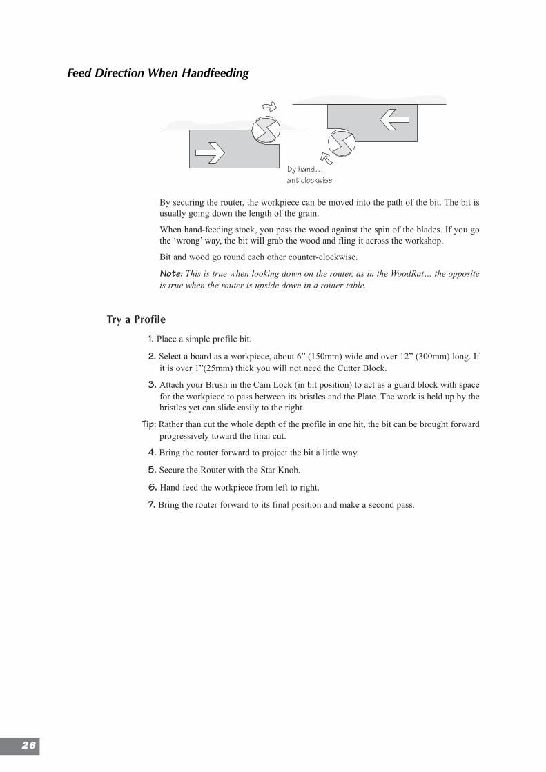
By securing the router, the workpiece can be moved into the path of the bit. The bit isusually going down the length of the grain.
When hand-feeding stock, you pass the wood against the spin of the blades. If you gothe ‘wrong’ way, the bit will grab the wood and fling it across the workshop.
Bit and wood go round each other counter-clockwise.
Note: This is true when looking down on the router, as in the WoodRat… the oppositeis true when the router is upside down in a router table.
Try a Profile
1. Place a simple profile bit.
2. Select a board as a workpiece, about 6” (150mm) wide and over 12” (300mm) long. Ifit is over 1”(25mm) thick you will not need the Cutter Block.
3. Attach your Brush in the Cam Lock (in bit position) to act as a guard block with spacefor the workpiece to pass between its bristles and the Plate. The work is held up by thebristles yet can slide easily to the right.
Tip: Rather than cut the whole depth of the profile in one hit, the bit can be brought forwardprogressively toward the final cut.
4. Bring the router forward to project the bit a little way
5. Secure the Router with the Star Knob.
6. Hand feed the workpiece from left to right.
7. Bring the router forward to its final position and make a second pass.
By hand…anticlockwise
ProfilesDecorative Profiles
Almost any bit can be used in the WoodRat to create decorative and functional profiles.
Generally profiles work down the grain, with the wood being fed by hand, but with theWoodRat you can down-cut, holding the stock in the Miter Box, in the Sugar Tong Vice,the Box, or clamped to the Mortise Rail to take the profile across the end grain as well.There’s more on that later.
Profiling on the WoodRat is similar to profiling on a spindle moulder or router table.Making profiled strips for decorative effect is best done by moulding the edge of aboard, supported by the Brush and cutting it off as a strip when finished.
Decorative Profiles
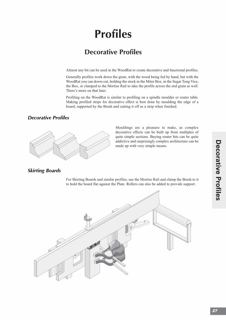
Mouldings are a pleasure to make, as complexdecorative effects can be built up from multiples ofquite simple sections. Buying router bits can be quiteaddictive and surprisingly complex architecture can bemade up with very simple means.
Skirting Boards
For Skirting Boards and similar profiles, use the Mortise Rail and clamp the Brush to itto hold the board flat against the Plate. Rollers can also be added to provide support.
27
Deco
rative Pro
files
2288
Functional ProfilesProfiles are generally decorative, but a large number can be considered working joints.Here are a few:
Rebates (Rabbets)
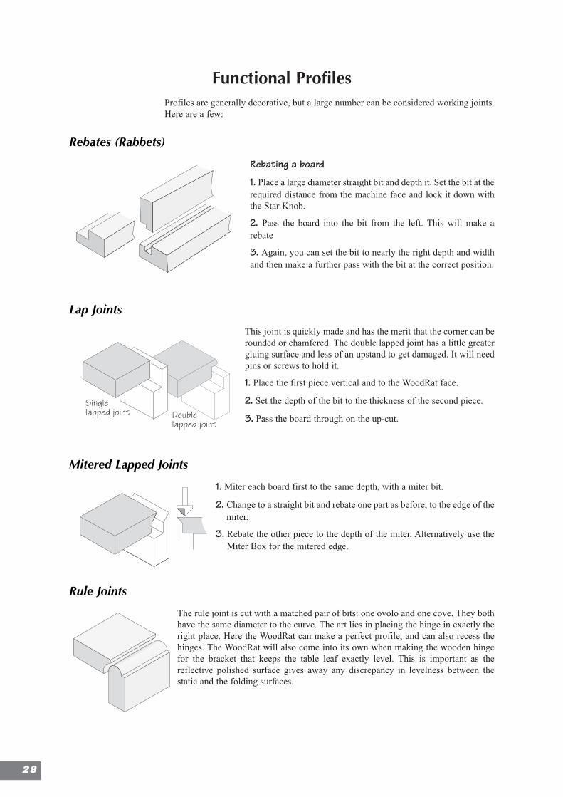
Rebating a board
1. Place a large diameter straight bit and depth it. Set the bit at therequired distance from the machine face and lock it down withthe Star Knob.
2. Pass the board into the bit from the left. This will make arebate
3. Again, you can set the bit to nearly the right depth and widthand then make a further pass with the bit at the correct position.
Lap Joints
This joint is quickly made and has the merit that the corner can berounded or chamfered. The double lapped joint has a little greatergluing surface and less of an upstand to get damaged. It will needpins or screws to hold it.
1. Place the first piece vertical and to the WoodRat face.
2. Set the depth of the bit to the thickness of the second piece.
3. Pass the board through on the up-cut.
Mitered Lapped Joints
1. Miter each board first to the same depth, with a miter bit.
2. Change to a straight bit and rebate one part as before, to the edge of themiter.
3. Rebate the other piece to the depth of the miter. Alternatively use theMiter Box for the mitered edge.
Rule Joints
The rule joint is cut with a matched pair of bits: one ovolo and one cove. They bothhave the same diameter to the curve. The art lies in placing the hinge in exactly theright place. Here the WoodRat can make a perfect profile, and can also recess thehinges. The WoodRat will also come into its own when making the wooden hingefor the bracket that keeps the table leaf exactly level. This is important as thereflective polished surface gives away any discrepancy in levelness between thestatic and the folding surfaces.
Singlelapped joint Double
lapped joint
Singlelapped joint Double
lapped joint
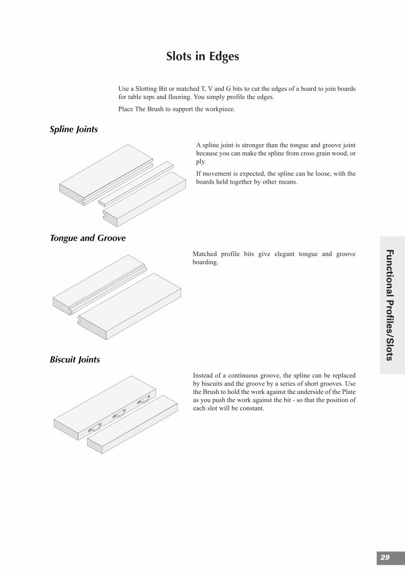
Slots in Edges
Use a Slotting Bit or matched T, V and G bits to cut the edges of a board to join boardsfor table tops and flooring. You simply profile the edges.
Place The Brush to support the workpiece.
Spline Joints
A spline joint is stronger than the tongue and groove jointbecause you can make the spline from cross grain wood, orply.
If movement is expected, the spline can be loose, with theboards held together by other means.
Tongue and Groove
Matched profile bits give elegant tongue and grooveboarding.
Biscuit Joints
Instead of a continuous groove, the spline can be replacedby biscuits and the groove by a series of short grooves. Usethe Brush to hold the work against the underside of the Plateas you push the work against the bit - so that the position ofeach slot will be constant.
29
Fun
ction
al Pro
files/Slo
ts
Routing Circles
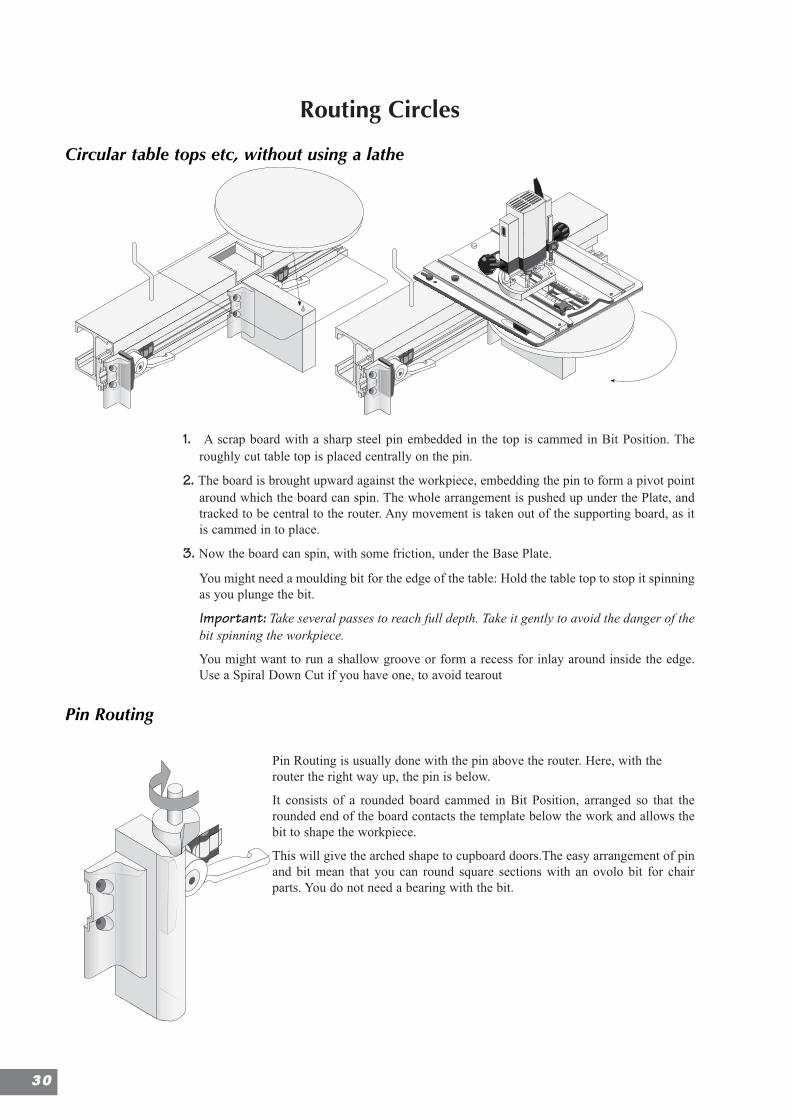
Circular table tops etc, without using a lathe
1. A scrap board with a sharp steel pin embedded in the top is cammed in Bit Position. Theroughly cut table top is placed centrally on the pin.
2. The board is brought upward against the workpiece, embedding the pin to form a pivot pointaround which the board can spin. The whole arrangement is pushed up under the Plate, andtracked to be central to the router. Any movement is taken out of the supporting board, as itis cammed in to place.
3. Now the board can spin, with some friction, under the Base Plate.
You might need a moulding bit for the edge of the table: Hold the table top to stop it spinningas you plunge the bit.
Important: Take several passes to reach full depth. Take it gently to avoid the danger of thebit spinning the workpiece.
You might want to run a shallow groove or form a recess for inlay around inside the edge.Use a Spiral Down Cut if you have one, to avoid tearout
Pin Routing
Pin Routing is usually done with the pin above the router. Here, with therouter the right way up, the pin is below.
It consists of a rounded board cammed in Bit Position, arranged so that therounded end of the board contacts the template below the work and allows thebit to shape the workpiece.
This will give the arched shape to cupboard doors.The easy arrangement of pinand bit mean that you can round square sections with an ovolo bit for chairparts. You do not need a bearing with the bit.
3300
Raising Panels
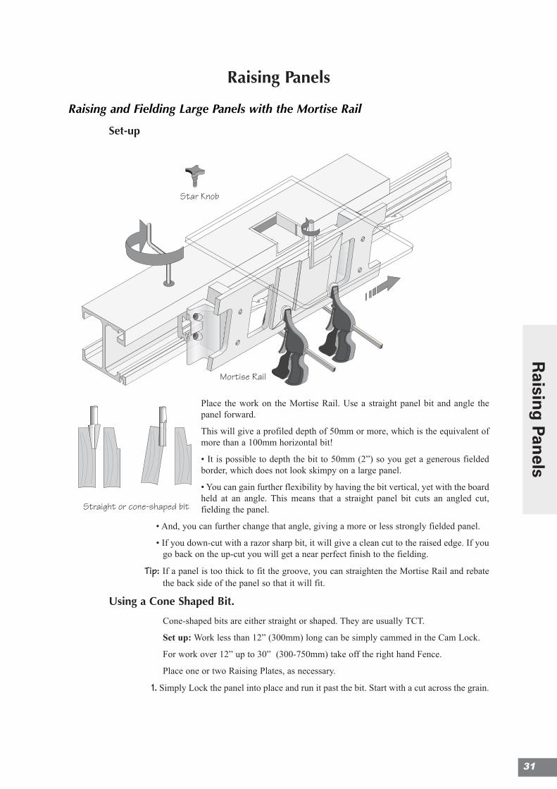
Raising and Fielding Large Panels with the Mortise Rail
Set-up
Place the work on the Mortise Rail. Use a straight panel bit and angle thepanel forward.
This will give a profiled depth of 50mm or more, which is the equivalent ofmore than a 100mm horizontal bit!
• It is possible to depth the bit to 50mm (2”) so you get a generous fieldedborder, which does not look skimpy on a large panel.
• You can gain further flexibility by having the bit vertical, yet with the boardheld at an angle. This means that a straight panel bit cuts an angled cut,fielding the panel.
• And, you can further change that angle, giving a more or less strongly fielded panel.
• If you down-cut with a razor sharp bit, it will give a clean cut to the raised edge. If yougo back on the up-cut you will get a near perfect finish to the fielding.
Tip: If a panel is too thick to fit the groove, you can straighten the Mortise Rail and rebatethe back side of the panel so that it will fit.
Using a Cone Shaped Bit.
Cone-shaped bits are either straight or shaped. They are usually TCT.
Set up: Work less than 12” (300mm) long can be simply cammed in the Cam Lock.
For work over 12” up to 30” (300-750mm) take off the right hand Fence.
Place one or two Raising Plates, as necessary.
1. Simply Lock the panel into place and run it past the bit. Start with a cut across the grain.
Raising & fielding a panelusing the Mortise Rail
Star Knob
Mortise Rail
Straight or cone-shaped bit
Raising & fielding a panelusing the Mortise Rail
Star Knob
Mortise Rail
Straight or cone-shaped bit
31
Raisin
g Pan
els
3322
2. Pass the panel from left to right with the bit in front of the panel. Run the panel back onthe up-cut, to clean the face of the fielded area. Cartwheel the panel between each cut.
Depending on the depth of the fielding, it may necessitate one or two passes. In whichcase leave the final depthing for the final cut.
3. Mark up the Guide Rail with the exact position of the final cut. The edge of the panelneeds to end up the right fit for the groove, leaving enough room for moisturemovement.
HorizontalThe panel is placed horizontally and flat and cut with a dish shaped bit. The cut ispredominantly horizontal. This means that the tips of the bit could be travelling at aspeed of well in excess of 100 mph. A router with controllable speed is thereforeessential - slow it down to 8,000 rpm.
This is fine, as long as the pass is well protected and the workpiece well supported. Thegreatest diameter of bit usable in the WoodRat is 86mm wide. However this will notgive a very wide band of fielding on a panel, particularly as 10mm is lost in the doorframe. Feeding by hand also gives tearout along the shoulder of the fielding.
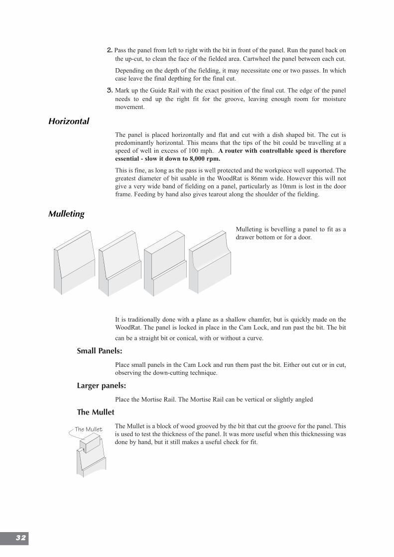
Mulleting
Mulleting is bevelling a panel to fit as adrawer bottom or for a door.
It is traditionally done with a plane as a shallow chamfer, but is quickly made on theWoodRat. The panel is locked in place in the Cam Lock, and run past the bit. The bit
can be a straight bit or conical, with or without a curve.
Small Panels:
Place small panels in the Cam Lock and run them past the bit. Either out cut or in cut,observing the down-cutting technique.
Larger panels:
Place the Mortise Rail. The Mortise Rail can be vertical or slightly angled
The Mullet
The Mullet is a block of wood grooved by the bit that cut the groove for the panel. Thisis used to test the thickness of the panel. It was more useful when this thicknessing wasdone by hand, but it still makes a useful check for fit.
The Mullet
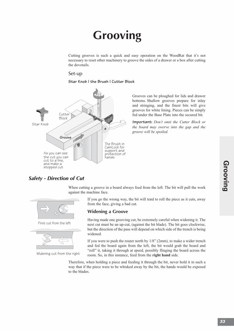
GroovingCutting grooves is such a quick and easy operation on the WoodRat that it’s notnecessary to reset other machinery to groove the sides of a drawer or a box after cuttingthe dovetails.
Set-up
Star Knob | the Brush | Cutter Block
Grooves can be ploughed for lids and drawerbottoms. Shallow grooves prepare for inlayand stringing, and the finest bits will givegrooves for white lining. Pieces can be simplyfed under the Base Plate into the secured bit.
Important: Don’t omit the Cutter Block orthe board may swerve into the gap and thegroove will be spoiled.
Safety - Direction of Cut
When cutting a groove in a board always feed from the left. The bit will pull the workagainst the machine face.
If you go the wrong way, the bit will tend to roll the piece as it cuts, awayfrom the face, giving a bad cut.
Widening a Groove
Having made one grooving cut, be extremely careful when widening it. Thenext cut must be an up-cut, (against the bit blade). The bit goes clockwise,but the direction of the pass will depend on which side of the trench is beingwidened.
If you were to push the router north by 1/8” (2mm), to make a wider trenchand fed the board again from the left, the bit would grab the board and“roll” it, taking it through at speed, possibly flinging the board across theroom. So, in this instance, feed from the right hand side.
Therefore, when holding a piece and feeding it through the bit, never hold it in such away that if the piece were to be whisked away by the bit, the hands would be exposedto the blades.
First cut from the left
Widening cut from the right
CutterBlock
The Brush inCamLock forsupport andprotection ofhands
As you can seethe cut you cancut to a line,and make astopped cut
Groove
Star Knob
33
Gro
oving
3344
Stopped Grooves
The WoodRat's advantage is that the cut can be stopped so that the groove does not runthrough the joint to the outside of the piece and look unsightly. If the brush is giving thecorrect pressure, a groove can be started or stopped anywhere along its travel. Thetechnique is to have enough upward push from the Brush, so that the bit will not makethe wood wander as it starts its cut, yet not so much that you cannot move theworkpiece.
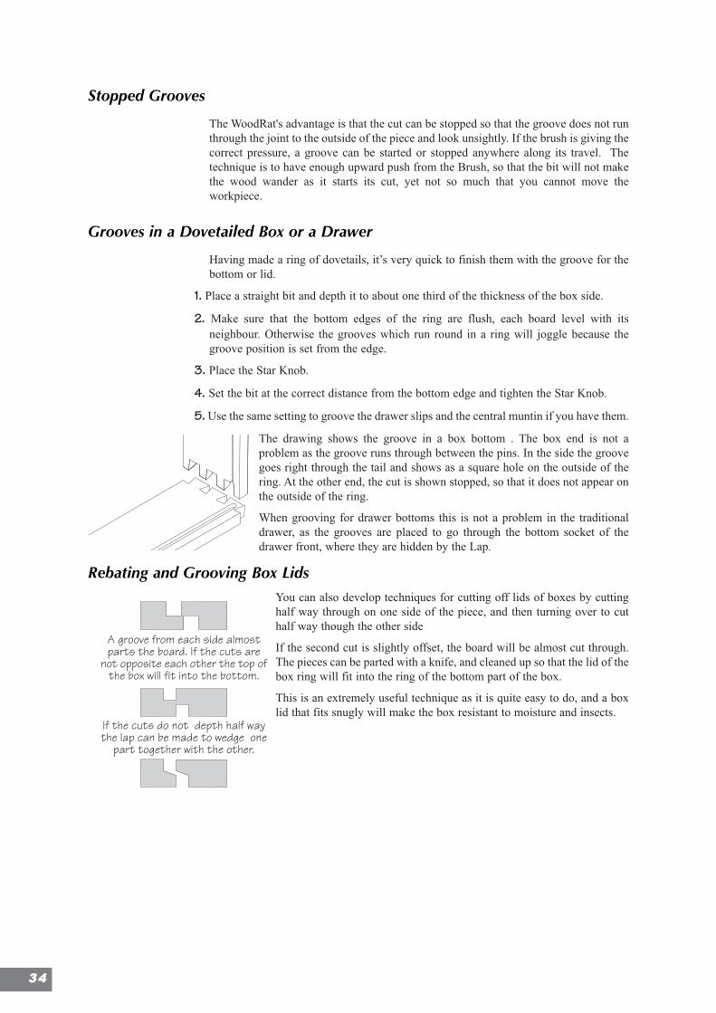
Grooves in a Dovetailed Box or a Drawer
Having made a ring of dovetails, it’s very quick to finish them with the groove for thebottom or lid.
1. Place a straight bit and depth it to about one third of the thickness of the box side.
2. Make sure that the bottom edges of the ring are flush, each board level with itsneighbour. Otherwise the grooves which run round in a ring will joggle because thegroove position is set from the edge.
3. Place the Star Knob.
4. Set the bit at the correct distance from the bottom edge and tighten the Star Knob.
5. Use the same setting to groove the drawer slips and the central muntin if you have them.
The drawing shows the groove in a box bottom . The box end is not aproblem as the groove runs through between the pins. In the side the groovegoes right through the tail and shows as a square hole on the outside of thering. At the other end, the cut is shown stopped, so that it does not appear onthe outside of the ring.
When grooving for drawer bottoms this is not a problem in the traditionaldrawer, as the grooves are placed to go through the bottom socket of thedrawer front, where they are hidden by the Lap.
Rebating and Grooving Box LidsYou can also develop techniques for cutting off lids of boxes by cuttinghalf way through on one side of the piece, and then turning over to cuthalf way though the other side
If the second cut is slightly offset, the board will be almost cut through.The pieces can be parted with a knife, and cleaned up so that the lid of thebox ring will fit into the ring of the bottom part of the box.
This is an extremely useful technique as it is quite easy to do, and a boxlid that fits snugly will make the box resistant to moisture and insects.
A groove from each side almostparts the board. If the cuts are
not opposite each other the top ofthe box will fit into the bottom.
If the cuts do not depth half waythe lap can be made to wedge one
part together with the other.
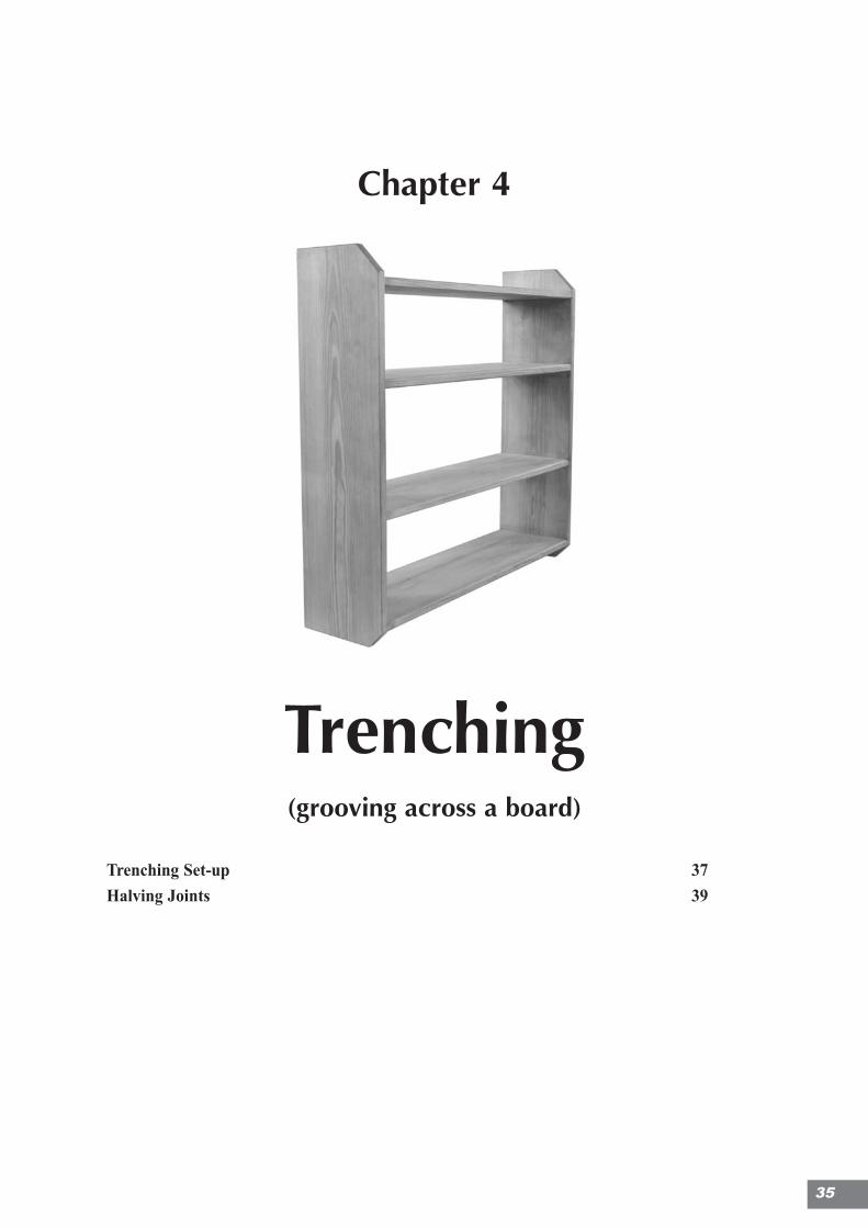
Chapter 4
Section 4
Trenching(grooving across a board)
Trenching Set-up 37
Halving Joints 39
35
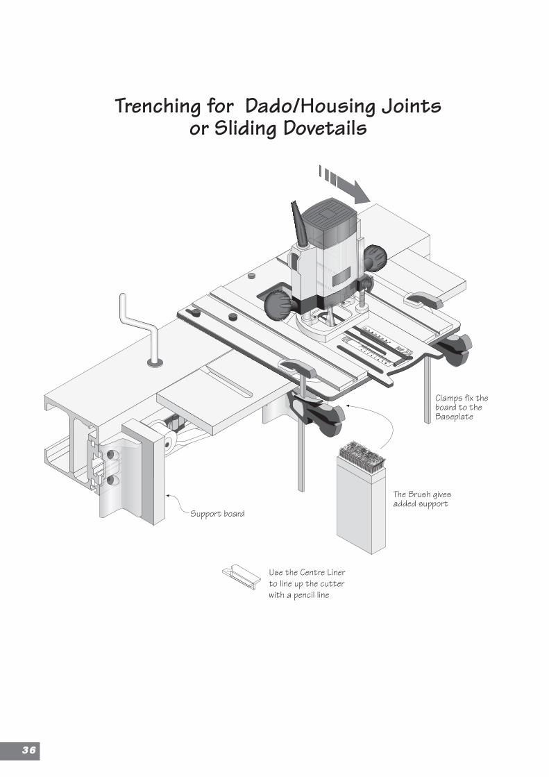
Clamps fix theboard to theBaseplate
The Brush givesadded support
Use the Centre Linerto line up the cutterwith a pencil line
Support board
Trenching for Dado/Housing Jointsor Sliding Dovetails
3366
Trenching(grooving across a board)
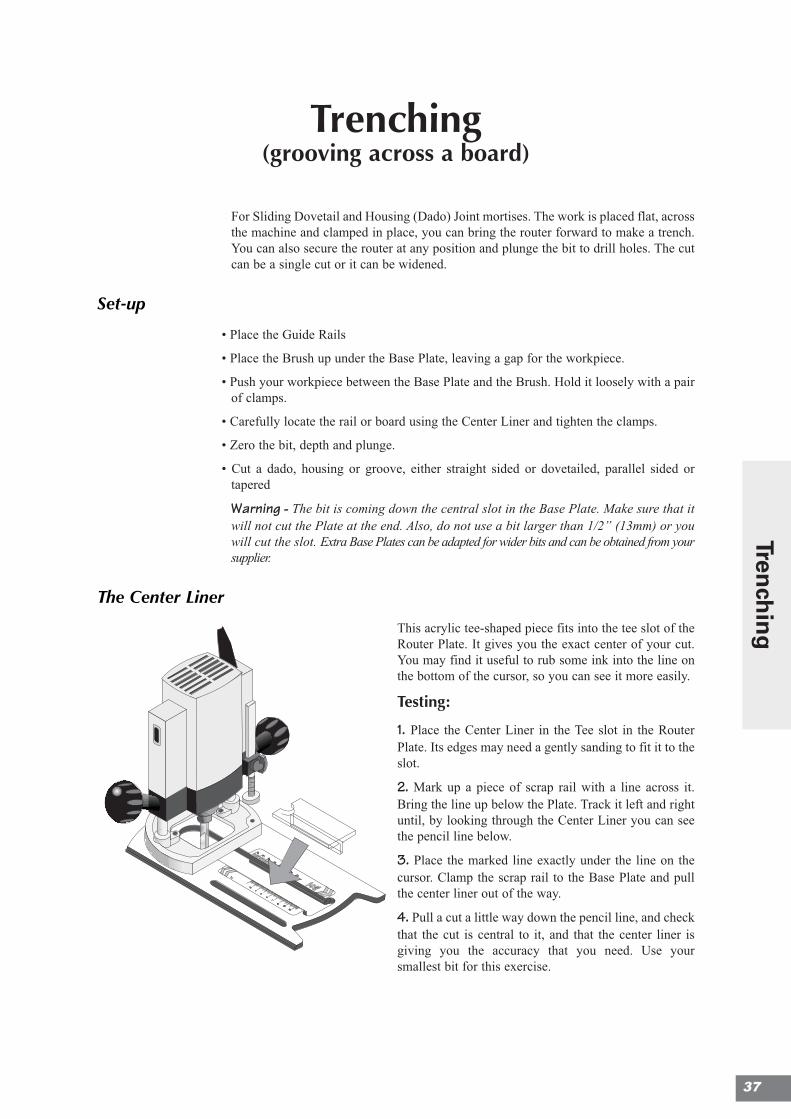
For Sliding Dovetail and Housing (Dado) Joint mortises. The work is placed flat, acrossthe machine and clamped in place, you can bring the router forward to make a trench.You can also secure the router at any position and plunge the bit to drill holes. The cutcan be a single cut or it can be widened.
Set-up
• Place the Guide Rails
• Place the Brush up under the Base Plate, leaving a gap for the workpiece.
• Push your workpiece between the Base Plate and the Brush. Hold it loosely with a pairof clamps.
• Carefully locate the rail or board using the Center Liner and tighten the clamps.
• Zero the bit, depth and plunge.
• Cut a dado, housing or groove, either straight sided or dovetailed, parallel sided ortapered
Warning - The bit is coming down the central slot in the Base Plate. Make sure that itwill not cut the Plate at the end. Also, do not use a bit larger than 1/2” (13mm) or youwill cut the slot. Extra Base Plates can be adapted for wider bits and can be obtained from yoursupplier.
The Center Liner
This acrylic tee-shaped piece fits into the tee slot of theRouter Plate. It gives you the exact center of your cut.You may find it useful to rub some ink into the line onthe bottom of the cursor, so you can see it more easily.
Testing:
1. Place the Center Liner in the Tee slot in the RouterPlate. Its edges may need a gently sanding to fit it to theslot.
2. Mark up a piece of scrap rail with a line across it.Bring the line up below the Plate. Track it left and rightuntil, by looking through the Center Liner you can seethe pencil line below.
3. Place the marked line exactly under the line on thecursor. Clamp the scrap rail to the Base Plate and pullthe center liner out of the way.
4. Pull a cut a little way down the pencil line, and checkthat the cut is central to it, and that the center liner isgiving you the accuracy that you need. Use yoursmallest bit for this exercise.
37
Trench
ing
Avoiding Tearout
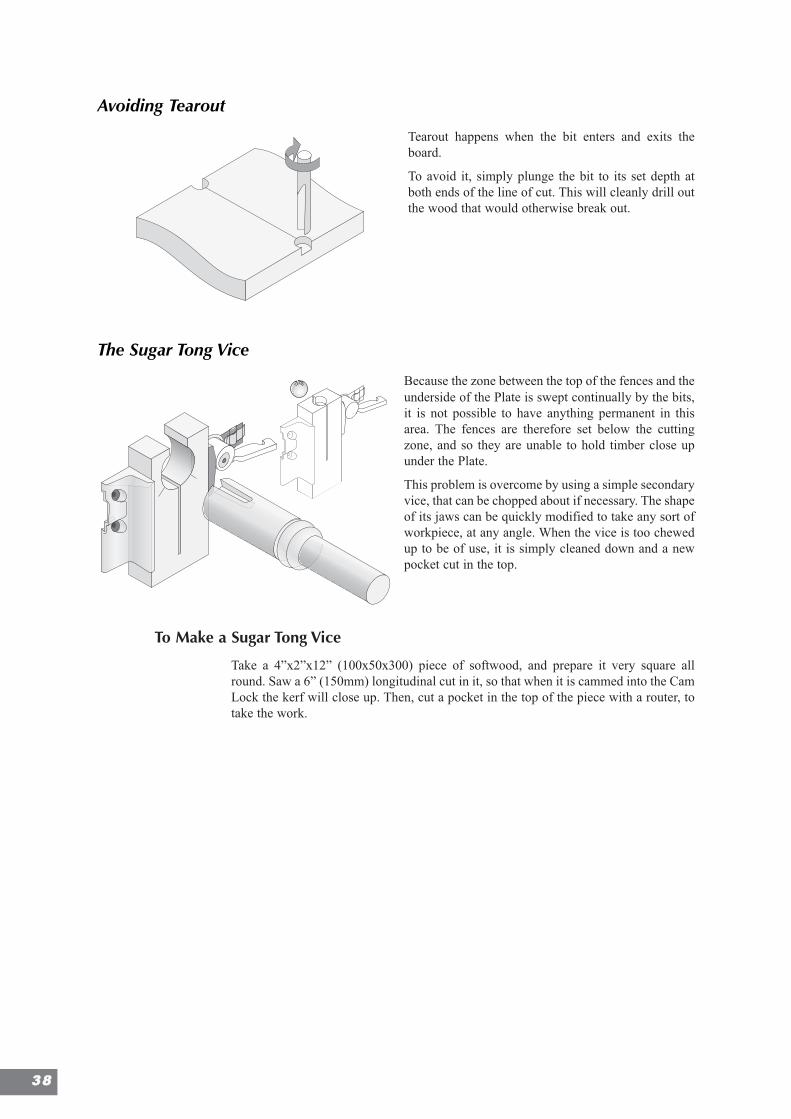
Tearout happens when the bit enters and exits theboard.
To avoid it, simply plunge the bit to its set depth atboth ends of the line of cut. This will cleanly drill outthe wood that would otherwise break out.
The Sugar Tong Vice
Because the zone between the top of the fences and theunderside of the Plate is swept continually by the bits,it is not possible to have anything permanent in thisarea. The fences are therefore set below the cuttingzone, and so they are unable to hold timber close upunder the Plate.
This problem is overcome by using a simple secondaryvice, that can be chopped about if necessary. The shapeof its jaws can be quickly modified to take any sort ofworkpiece, at any angle. When the vice is too chewedup to be of use, it is simply cleaned down and a newpocket cut in the top.
To Make a Sugar Tong Vice
Take a 4”x2”x12” (100x50x300) piece of softwood, and prepare it very square allround. Saw a 6” (150mm) longitudinal cut in it, so that when it is cammed into the CamLock the kerf will close up. Then, cut a pocket in the top of the piece with a router, totake the work.
Hole to take a nailto steady the board
if necessary
The 2 x M8 counter-sunkscrews for the fixed
fences are used to fix thebracket to the sliding bar
from behind
Knot
Extension Bracket
The wire is relaid in thecounterbored hole andrewired in the sameconfiguration as before
Sliding BarTake off the FixedFences, and make theCamLock between theExtension Bracket andthe Sliding Fence
Sugar tong vice to holddifficult shape so that itcan be cut with a difficultshape
This design of Boxcan be used both ways upallowing work eitherFlat Across or Flat Square tothe machine face.
Dovetail key strengthensthe two wings and forms ahook to hook into the teeslot on the sliding bar.
Jig to give singleangle tenon
Jig with two splayedangles to givecompound tenon
Dovetail key strengthensthe two wings and forms ahook to hook into the teeslot on the sliding bar.
3388
Halving Joints (Half-lap Joints)
Frames, screens and grating are made with halving joints. There are two basic ways ofmaking them;
• Cutting the joint to the width of the finished workpiece
• Cutting the joint first in a plank and then slitting the wood to to the width of the joint
Halving Joint Variants
Cross Halving Joints
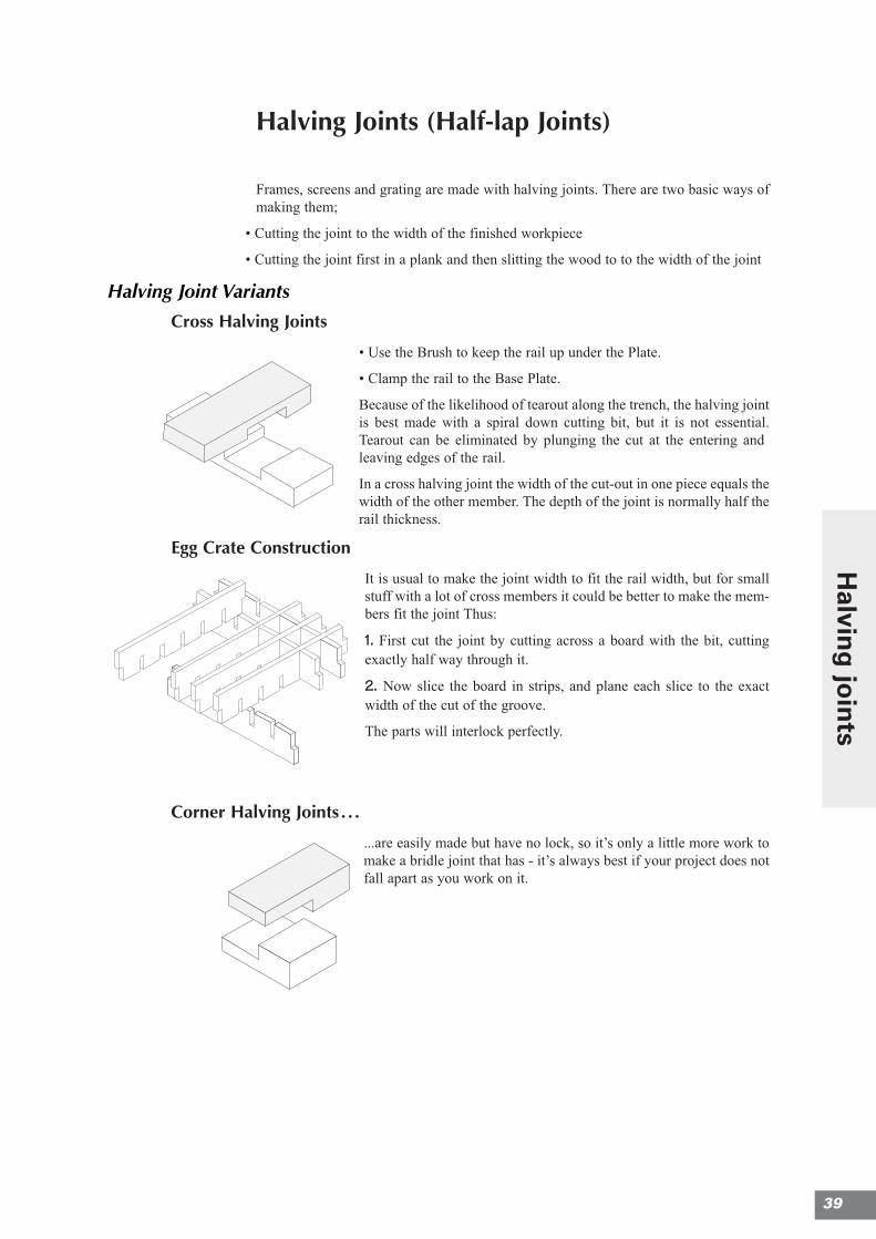
• Use the Brush to keep the rail up under the Plate.
• Clamp the rail to the Base Plate.
Because of the likelihood of tearout along the trench, the halving jointis best made with a spiral down cutting bit, but it is not essential.Tearout can be eliminated by plunging the cut at the entering andleaving edges of the rail.
In a cross halving joint the width of the cut-out in one piece equals thewidth of the other member. The depth of the joint is normally half therail thickness.
Egg Crate Construction
It is usual to make the joint width to fit the rail width, but for smallstuff with a lot of cross members it could be better to make the mem-bers fit the joint Thus:
1. First cut the joint by cutting across a board with the bit, cuttingexactly half way through it.
2. Now slice the board in strips, and plane each slice to the exactwidth of the cut of the groove.
The parts will interlock perfectly.
Corner Halving Joints . . .
...are easily made but have no lock, so it’s only a little more work tomake a bridle joint that has - it’s always best if your project does notfall apart as you work on it.
39
Halvin
g jo
ints
Cogged Halving Joints
This joint is used where the lower member is load bearing. The top member issimply notched, so that it retains most of its strength. Pockets are cut in the lowerpiece.
When routed, they will have rounded corners that will need to be squared with achisel.
Oblique Halving Joints
These are made with the ‘Rat set up as for dovetailing (see dovetailing section fordetails).
With the Center Plate, Spirals and Front Stop in place, the forward cut is made withthe Router Plate twisted against the left-hand spiral. The cuts can be either throughor stopped, but will be limited by the router base hitting the stop block in the CenterPlate.
For longer cuts, bring the Center Plate forward, and gain extra space by bringingthe whole Base Plate forward into First Position.
Place the large Allen key in the stop block on the Center Plate (as for Drawer-FrontDovetails) and secure with a Star Knob to get consistent, stopped cuts.
Otherwise you can angle the workpiece by bringing it forward a little and forming aconstant angle with a fence clamped up under the Plate. Use the Guide Rails and theRaising Plates if necessary.
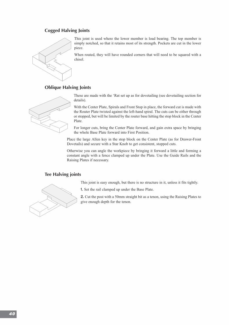
Tee Halving joints
This joint is easy enough, but there is no structure in it, unless it fits tightly.
1. Set the rail clamped up under the Base Plate.
2. Cut the post with a 50mm straight bit as a tenon, using the Raising Plates togive enough depth for the tenon.
4400
Chapter 5
TenoningTenoning Set-up 43
Sliding Dovetail Guide: Shelving 44Putting a leg on a table 47
Chair Making 48
More Joints with tenons 49
41
Halvin
g jo
ints
Tenoning
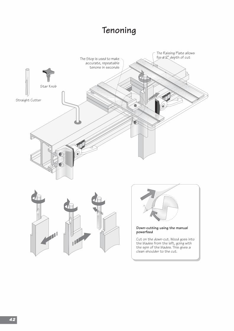
Star Knob
Straight Cutter
The Raising Plate allowsfor a 2” depth of cutThe Stop is used to make
accurate, repeatabletenons in seconds
Down-cutting using the manualpowerfeed
Cut on the down-cut. Wood goes intothe blades from the left, going withthe spin of the blades. This gives aclean shoulder to the cut.
4422
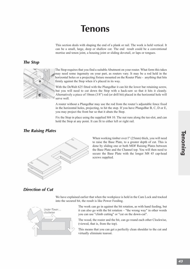
TenonsThis section deals with shaping the end of a plank or rail. The work is held vertical. Itcan be a small, large, deep or shallow cut. The end result could be a conventionalmortise and tenon joint, a housing joint or sliding dovetail, or laps or tongues.
The Stop
The Stop requires that you find a suitable Abutment on your router. What form this takesmay need some ingenuity on your part, as routers vary. It may be a rod held in thehorizontal holes or a projecting fixture mounted on the Router Plate - anything that hitsfirmly against the Stop when it’s placed in its way.
With the DeWalt 625 fitted with the PlungeBar it can hit the lower bar retaining screw,but you will need to cut down the Stop with a hack-saw so that it hits it cleanly.Alternatively a piece of 10mm (3/8”) rod (or drill bit) placed in the horizontal hole willserve well.
A router without a PlungeBar may use the rod from the router’s adjustable fence fixedin the horizontal holes, projecting, to hit the stop. If you have PlungeBar B, C, D or E,you may project the front bar so that it abuts the Stop.
Fix the Stop in place using the supplied M4 10. The nut runs along the tee-slot, and canhold the Stop at any point. It can fit to either left or right rail.
The Raising Plates
When working timber over l” (25mm) thick, you will needto raise the Base Plate, to a greater depth of cut. This isdone by sliding one or both MDF Raising Plates betweenthe Base Plate and the Channel top. You will then need tosecure the Base Plate with the longer M8 45 cap-headscrews supplied.
Direction of Cut
We have explained earlier that when the workpiece is held in the Cam Lock and trackedinto the secured bit, the result is like Power Feeding.
The work can go in against the bit rotation, as with hand feeding, butit can also go with the bit rotation – "the wrong way" in other wordsyou can use "climb cutting" or "cut on the down-cut".
The wood, the router and the bit, can go round each other Clockwise,(viewed, that is, from the top).
This means that you can get a perfectly clean shoulder to the cut andvirtually eliminate tearout.
Under Power…clockwise
First Position
Second Position
Third Position
This first (top left) hole is left withouta rivet, when the grid is upside down.
spar
bar
tapdown the rivetwith a light hammer
barspar
hole in the workbench
RaisingPlates
identifying parts
Second Line
First Line
Third Line
Tenoning
Star Knob
Straight Cutter
The Raising Plate allowsfor a 2” depth of cutThe Stop is used to make
accurate, repeatabletenons in seconds
Down-cutting using the manualpowerfeed
Cut on the down-cut. Wood goes intothe blades from the left, going withthe spin of the blades. This gives aclean shoulder to the cut.
43
Teno
nin
g
.
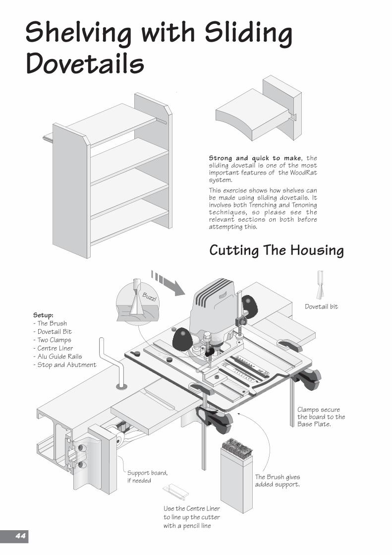
Use the Centre Linerto line up the cutterwith a pencil line
Clamps securethe board to theBase Plate.
The Brush givesadded support.
Cutting The Housing
Strong and quick to make, thesliding dovetail is one of the mostimportant features of the WoodRatsystem.This exercise shows how shelves canbe made using sliding dovetails. Itinvolves both Trenching and Tenoningtechniques, so please see therelevant sections on both beforeattempting this.
Shelving with SlidingDovetails
Dovetail bit
Support board,if needed
Setup:- The Brush- Dovetail Bit- Two Clamps- Centre Liner- Alu Guide Rails- Stop and Abutment
Buzz!
4444
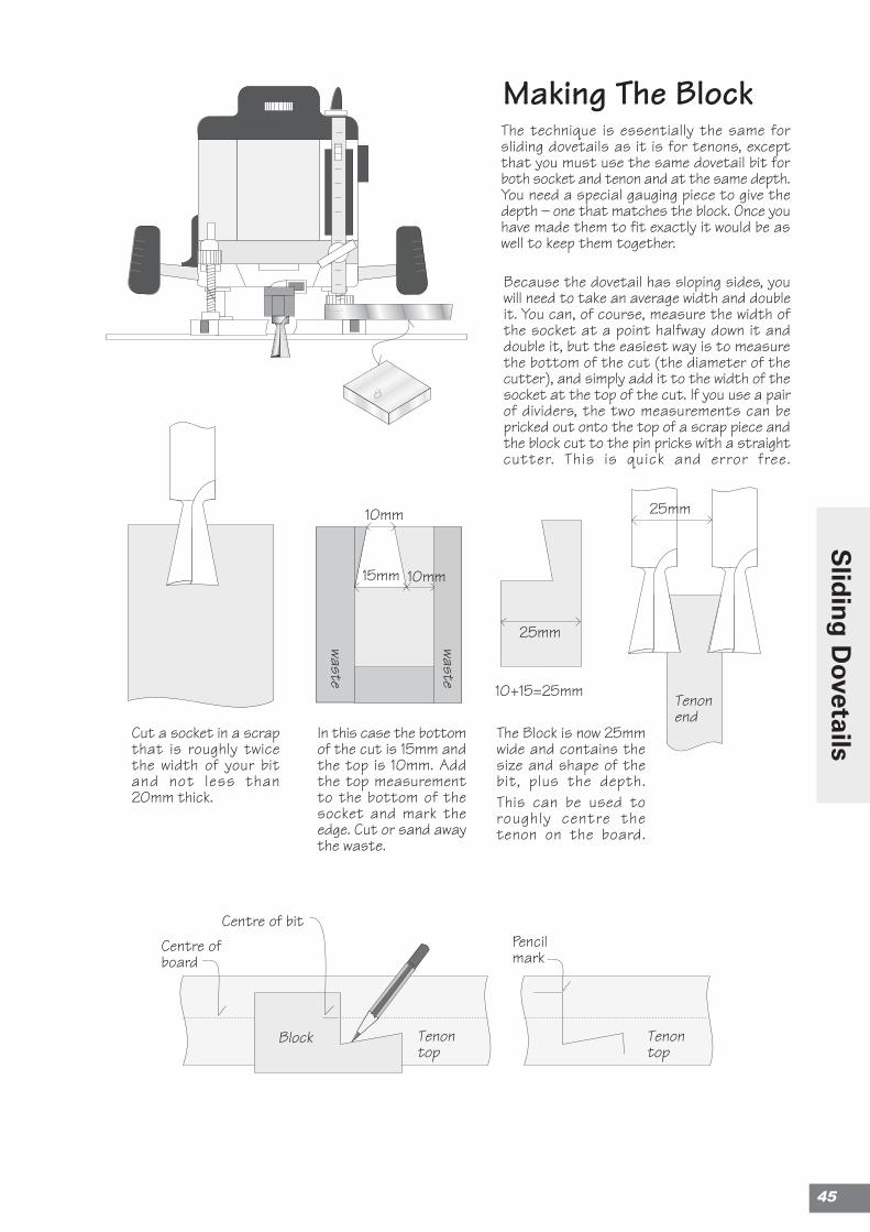
Making The Block
Because the dovetail has sloping sides, youwill need to take an average width and doubleit. You can, of course, measure the width ofthe socket at a point halfway down it anddouble it, but the easiest way is to measurethe bottom of the cut (the diameter of thecutter), and simply add it to the width of thesocket at the top of the cut. If you use a pairof dividers, the two measurements can bepricked out onto the top of a scrap piece andthe block cut to the pin pricks with a straightcutter. This is quick and error free.
The technique is essentially the same forsliding dovetails as it is for tenons, exceptthat you must use the same dovetail bit forboth socket and tenon and at the same depth.You need a special gauging piece to give thedepth – one that matches the block. Once youhave made them to fit exactly it would be aswell to keep them together.
Cut a socket in a scrapthat is roughly twicethe width of your bitand not less than20mm thick.
In this case the bottomof the cut is 15mm andthe top is 10mm. Addthe top measurementto the bottom of thesocket and mark theedge. Cut or sand awaythe waste.
The Block is now 25mmwide and contains thesize and shape of thebit, plus the depth.This can be used toroughly centre thetenon on the board.
10+15=25mm
25mm
Tenonend
25mm
10mm
10mm
waste
waste
15mm
Tenontop
Centre of bit
Block Tenontop
Centre ofboard
Pencilmark
45
Slid
ing
Dovetails
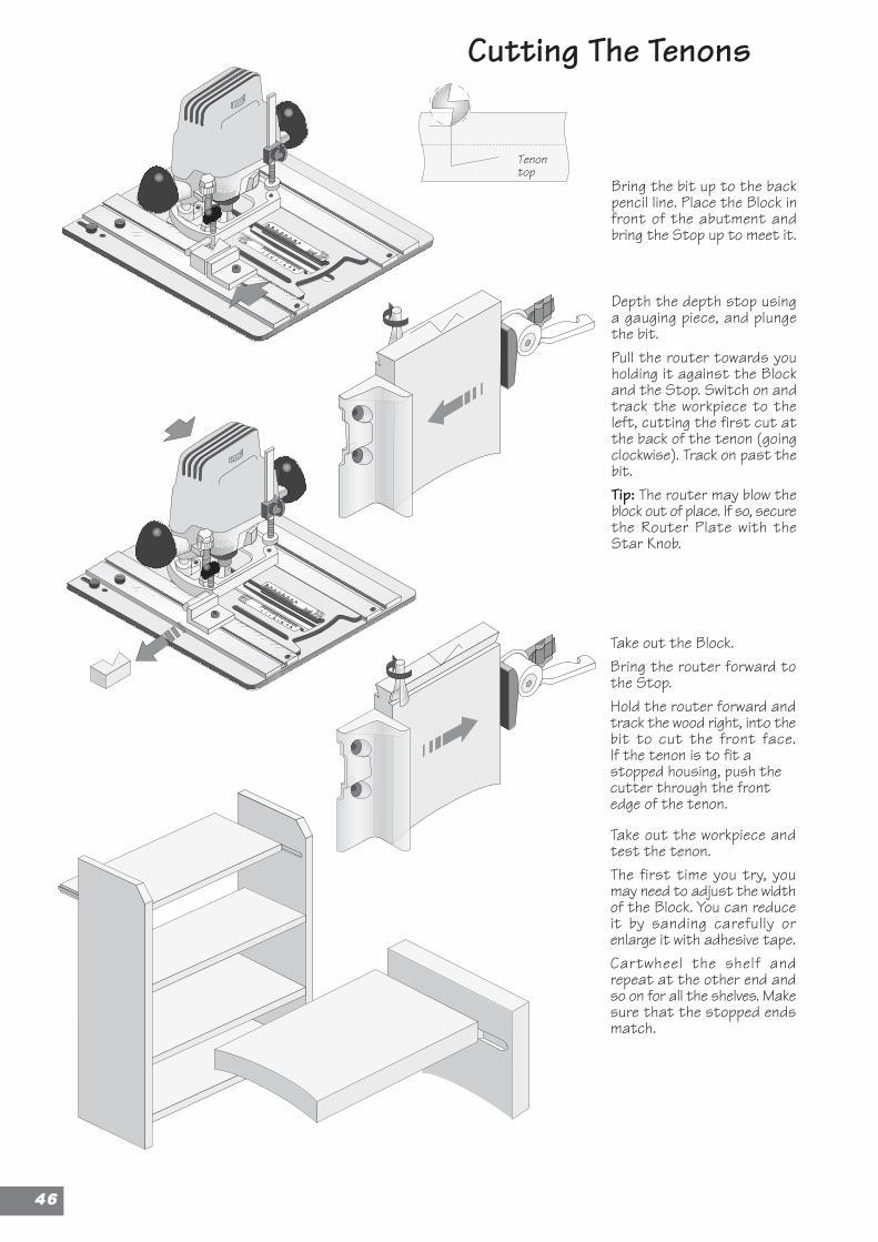
Cutting The Tenons
Take out the Block.Bring the router forward tothe Stop.Hold the router forward andtrack the wood right, into thebit to cut the front face.If the tenon is to fit astopped housing, push thecutter through the frontedge of the tenon.
Take out the workpiece andtest the tenon.The first time you try, youmay need to adjust the widthof the Block. You can reduceit by sanding carefully orenlarge it with adhesive tape.Cartwheel the shelf andrepeat at the other end andso on for all the shelves. Makesure that the stopped endsmatch.
Depth the depth stop usinga gauging piece, and plungethe bit.Pull the router towards youholding it against the Blockand the Stop. Switch on andtrack the workpiece to theleft, cutting the first cut atthe back of the tenon (goingclockwise). Track on past thebit.Tip: The router may blow theblock out of place. If so, securethe Router Plate with theStar Knob.
Bring the bit up to the backpencil line. Place the Block infront of the abutment andbring the Stop up to meet it.
Tenontop
4466
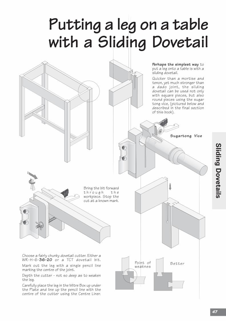
Putting a leg on a tablewith a Sliding Dovetail
Perhaps the simplest way toput a leg onto a table is with asliding dovetail.Quicker than a mortise andtenon, yet much stronger thana dado joint, the slidingdovetail can be used not onlywith square pieces, but alsoround pieces using the sugartong vice, (pictured below anddescribed in the final sectionof this book).
Choose a fairly chunky dovetail cutter. Either aWR-H-6-36-20 or a TCT dovetail bit.Mark out the leg with a single pencil linemarking the centre of the joint.Depth the cutter - not so deep as to weakenthe leg.Carefully place the leg in the Mitre Box up underthe Plate and line up the pencil line with thecentre of the cutter using the Centre Liner.
Bring the bit forwardt h r o u g h t h eworkpiece. Stop thecut at a known mark.
Sugartong Vice
BetterPoint ofweaknes
47
Slid
ing
Dovetails
Chair Making
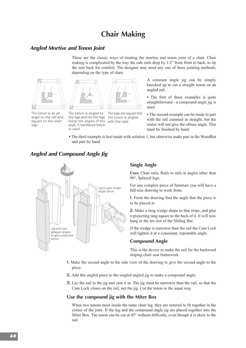
Angled Mortise and Tenon Joint
These are the classic ways of treating the mortise and tenon joint of a chair. Chairmaking is complicated by the way the side rails drop by 1/2” from front to back, to tipthe seat back for comfort. The designer may need any one of these jointing methods,depending on the type of chair.
A constant angle jig can be simplyknocked up to cut a straight tenon on anangled rail.
• The first of these examples is quitestraightforward - a compound angle jig isused
• The second example can be made in partwith the rail cammed in straight, but therouter will not give the obtuse angle. Thismust be finished by hand.
• The third example is best made with solution 1, but otherwise make part in the WoodRatand part by hand.
Angled and Compound Angle Jig
Single Angle
Uses: Chair rails, Rails to rails at angles other than90°, Splayed legs,
For any complex piece of furniture you will have afull-size drawing to work from.
1. From the drawing find the angle that the piece isto be placed at.
2. Make a long wedge shape to that slope, and gluea projecting tang square to the back of it. It will nowhang in the tee slot of the Sliding Bar.
If the wedge is narrower than the rail the Cam Lockwill tighten it at a consistent, repeatable angle.
Compound Angle
This is the device to make the rail for the backwardsloping chair seat framework.
1. Make the second angle to the side view of the drawing to give the second angle to thepiece.
2. Add this angled piece to the singled angled jig to make a compound angle.
3. Lay the rail in the jig and cam it in. The jig must be narrower than the rail, so that theCam Lock closes on the rail, not the jig. Cut the tenon in the usual way.
Use the compound jig with the Miter Box
When two tenons meet inside the same chair leg, they are mitered to fit together in thecorner of the joint. If the leg and the compound angle jig are placed together into theMiter Box. The tenon can be cut at 45° without difficulty, even though it is skew to therail.
Jig to give singleangle tenon
Jig with twosplayed anglesto give compoundtenon
The tenon is at anangle to the rail andsquare to the chairlegs
The tenon is angled tothe legs and the the legsfollow the angles of theseat. A barefaced tenonis used
The legs are square butthe tenon is angledwith the rails
4488
More Joints with Tenons
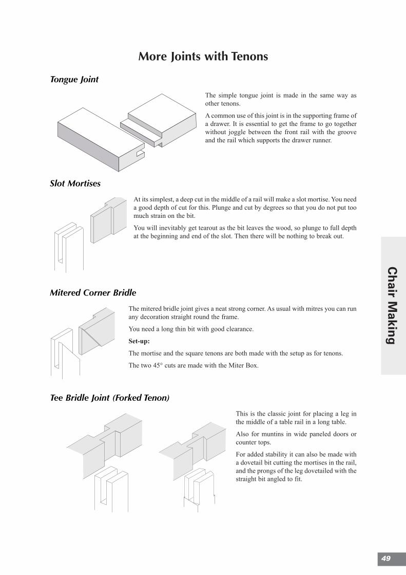
Tongue Joint
The simple tongue joint is made in the same way asother tenons.
A common use of this joint is in the supporting frame ofa drawer. It is essential to get the frame to go togetherwithout joggle between the front rail with the grooveand the rail which supports the drawer runner.
Slot Mortises
At its simplest, a deep cut in the middle of a rail will make a slot mortise. You needa good depth of cut for this. Plunge and cut by degrees so that you do not put toomuch strain on the bit.
You will inevitably get tearout as the bit leaves the wood, so plunge to full depthat the beginning and end of the slot. Then there will be nothing to break out.
Mitered Corner Bridle
The mitered bridle joint gives a neat strong corner. As usual with mitres you can runany decoration straight round the frame.
You need a long thin bit with good clearance.
Set-up:
The mortise and the square tenons are both made with the setup as for tenons.
The two 45° cuts are made with the Miter Box.
Tee Bridle Joint (Forked Tenon)
This is the classic joint for placing a leg inthe middle of a table rail in a long table.
Also for muntins in wide paneled doors orcounter tops.
For added stability it can also be made witha dovetail bit cutting the mortises in the rail,and the prongs of the leg dovetailed with thestraight bit angled to fit.
49
Ch
air Makin
g
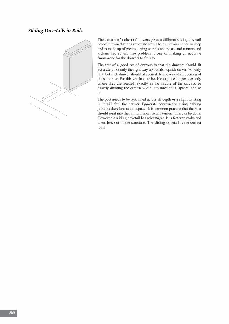
Sliding Dovetails in Rails
The carcase of a chest of drawers gives a different sliding dovetailproblem from that of a set of shelves. The framework is not so deepand is made up of pieces, acting as rails and posts, and runners andkickers and so on. The problem is one of making an accurateframework for the drawers to fit into.
The test of a good set of drawers is that the drawers should fitaccurately not only the right way up but also upside down. Not onlythat, but each drawer should fit accurately in every other opening ofthe same size. For this you have to be able to place the posts exactlywhere they are needed: exactly in the middle of the carcass, orexactly dividing the carcass width into three equal spaces, and soon.
The post needs to be restrained across its depth or a slight twistingin it will foul the drawer. Egg-crate construction using halvingjoints is therefore not adequate. It is common practise that the postshould joint into the rail with mortise and tenons. This can be done.However, a sliding dovetail has advantages. It is faster to make andtakes less out of the structure. The sliding dovetail is the correctjoint.
5500
Chapter 6
MortisingMortising 51Mortising Set-up 53
Recesses for hinges and locks 55
Mortise & Tenon Guide: Making a Panelled Door 56Dowels 62
Dowel Joints 63
51
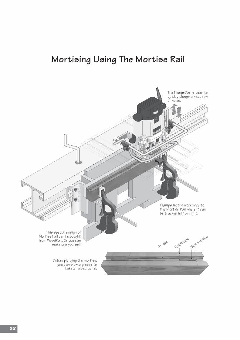
Before plunging the mortise,you can plow a groove to
take a raised panel.
Clamps fix the workpiece tothe Mortise Rail where it canbe tracked left or right.
This special design ofMortise Rail can be boughtfrom WoodRat. Or you can
make one yourself
The PlungeBar is used toquickly plunge a neat rowof holes.
Mortising Using The Mortise Rail
GroovePen
cil Line
Slot mortis
e
5522
Mortising
The mortise and tenon is the joint of framing, for furniture and for large timberconstruction. The joint has many forms to suit conditions as different as the king-postof a roof truss and a center rail of a panelled door.
Mortises on the WoodRat
Mortises are traditionally cut before the tenon because they are a bit more difficult toadjust if they are made the wrong size. Shaving a sliver off the tenon is easier thantrimming a mortise.
Another useful jointing machine is the hollow chisel mortiser. They make squaremortises with flatish bottoms with ease. When it comes to general mortising they arefaster than the WoodRat, because the socket is cut with square corners. But whereas onemay not consider mortising a five barred gate on the WoodRat, there are jobs, forexample smaller mortises, or dovetailed mortises, or mortises that you don’t have achisel for, where the WoodRat is excellent.
It is also much more sensitive for chair making than the average chisel mortiser. TheWoodRat has the advantage of its fine tracking mechanism, and the ability to offer upawkward shapes and also to work at particular angles. Besides, not everyone owns amortiser.
Set-up
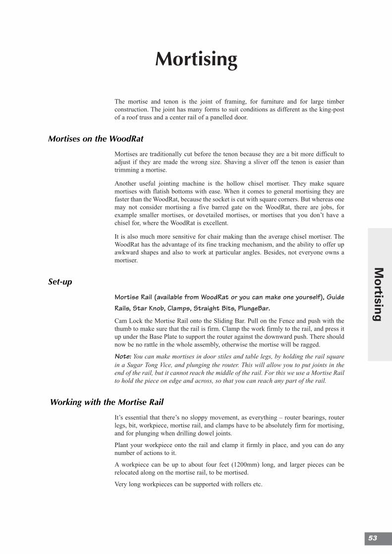
Mortise Rail (available from WoodRat or you can make one yourself), GuideRails, Star Knob, Clamps, Straight Bits, PlungeBar.
Cam Lock the Mortise Rail onto the Sliding Bar. Pull on the Fence and push with thethumb to make sure that the rail is firm. Clamp the work firmly to the rail, and press itup under the Base Plate to support the router against the downward push. There shouldnow be no rattle in the whole assembly, otherwise the mortise will be ragged.
Note: You can make mortises in door stiles and table legs, by holding the rail squarein a Sugar Tong Vice, and plunging the router. This will allow you to put joints in theend of the rail, but it cannot reach the middle of the rail. For this we use a Mortise Railto hold the piece on edge and across, so that you can reach any part of the rail.
Working with the Mortise Rail
It’s essential that there’s no sloppy movement, as everything – router bearings, routerlegs, bit, workpiece, mortise rail, and clamps have to be absolutely firm for mortising,and for plunging when drilling dowel joints.
Plant your workpiece onto the rail and clamp it firmly in place, and you can do anynumber of actions to it.
A workpiece can be up to about four feet (1200mm) long, and larger pieces can berelocated along on the mortise rail, to be mortised.
Very long workpieces can be supported with rollers etc.
53
Mo
rtising
Cutting the Mortise.
1. Zero the bit. Set the depth stop to the correct depth for the bit. Plunge the router to drilla hole, 3mm from the left-hand end of the mortise. Un-plunge it at intervals to clear it,as it goes down.
2. Stop the router and find the exact left-hand end of the mortise, by placing the bit overthe position. Start up again, and plunge the hole. Now clear right to the first hole, bytracking the work.
3. Plunge the next hole a little away from the first hole (on the right of it) and clear backto the first hole. The slot widens now. The next plunge is on the right of the slot, plunge,and clear back. Do this right up until the last hole, which may be exactly located, asbefore, with the router switched off.
Warnings
The object of this technique is to put as little strain as possible on the bit. It’s rather likechopping mortises with a chisel, but using the bit instead. If the bit judders in the holeas you plunge, it is telling you that your work, or your router, is not firmly secured.Make sure that you have pulled the Fence forward as you tighten the Cam Lock on theMortise Rail.
• If it burns as you plunge the bit, then it’s telling you that you’re chopping out more inone bite than you should. Don’t over do it. Always use a razor sharp bit, with a goodend cut.
The Rounded Ends
Mortises made with a bit have naturally got rounded ends, though the tenons are cutsquare. The remedy is either to chisel the mortise square ended, which is the proper wayto finish it, or to leave it rounded, and round off the tenons to fit. The second way isquickest as they don’t have to be exactly rounded to fit.
With through tenons there’s no contest: one should always square the corners, becauseit makes a stronger joint, and looks better, especially when the joint is wedged. But evenwhen the joint is invisible, it’s still best to square the mortises: it also more closelymatches traditional work, and like those rounded corners that jigs make under dovetails,may be they cannot be seen, but you know that they are there. \
To Make a Mortise Rail:
1. Make two 2" x 3" x 9" / 50 x 75 x 225mm (approx.) pieces, and place them upright ineither Cam Lock.
2. Screw a board of MDF or plywood, of whatever size you need, onto the uprights, as aMortise Rail. It will now lie parallel to the face of the machine.
3. Mark out holes in the board. The holes are for you to put the toe of the clamp into soyou can clamp your workpiece to the face of the MDF. Klemmsia or QuickClamps arebest, as they work single handed.
4. Tip the whole Mortise Rail assembly up, so that the face of the MDF lies up under thePlate. Cut out the holes with a long straight bit. The holes need to be large enough toput your hand through, because when you un-clamp and put the device in again vertical,you can pull on the Fence with your fingers, and push with your thumb, so that you takeany rattle out of the sliding bar. It is essential that there be no movement, as everythinghas to be absolutely firm for mortising, and for plunging when drilling dowel joints.
5. Now plant your workpiece onto the Mortise Rail and clamp it firmly in place.
5544
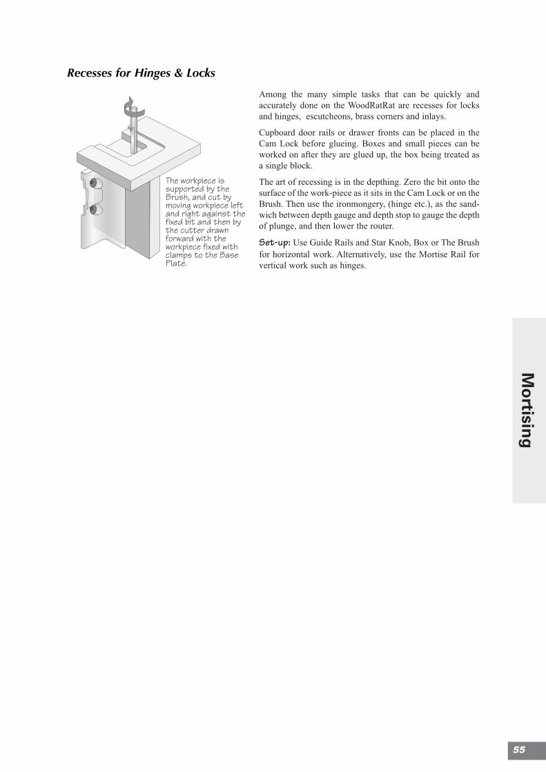
Recesses for Hinges & Locks
Among the many simple tasks that can be quickly andaccurately done on the WoodRatRat are recesses for locksand hinges, escutcheons, brass corners and inlays.
Cupboard door rails or drawer fronts can be placed in theCam Lock before glueing. Boxes and small pieces can beworked on after they are glued up, the box being treated asa single block.
The art of recessing is in the depthing. Zero the bit onto thesurface of the work-piece as it sits in the Cam Lock or on theBrush. Then use the ironmongery, (hinge etc.), as the sand-wich between depth gauge and depth stop to gauge the depthof plunge, and then lower the router.
Set-up: Use Guide Rails and Star Knob, Box or The Brushfor horizontal work. Alternatively, use the Mortise Rail forvertical work such as hinges.
The workpiece issupported by theBrush, and cut bymoving workpiece leftand right against thefixed bit and then bythe cutter drawnforward with theworkpiece fixed withclamps to the BasePlate.
55
Mo
rtising
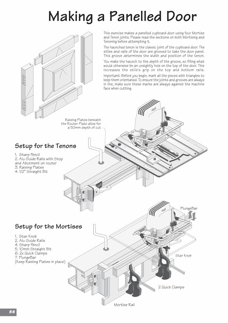
Making a Panelled Door
Raising Plates beneaththe Router Plate allow for
a 50mm depth of cut
This exercise makes a panelled cupboard door using four Mortiseand Tenon joints. Please read the sections on both Mortising andTenoning before attempting it.The haunched tenon is the classic joint of the cupboard door. Thestiles and rails of the door are grooved to take the door panel.This groove determines the width and position of the tenon.You make the haunch to the depth of the groove, so filling whatwould otherwise be an unsightly hole on the top of the door. Thisincreases the stile's grip on the top and bottom rails.Important: Before you begin, mark all the pieces with triangles tokeep them orientated. To ensure the joints and grooves are alwaysin line, make sure these marks are always against the machineface when cutting.
Setup for the Tenons
Setup for the Mortises
1. Sharp Pencil2. Alu Guide Rails with Stopand Abutment on router3. Raising Plates4. 1/2” Straight Bit
1. Star Knob2. Alu Guide Rails4. Sharp Pencil5. 10mm Straight Bit6. 2x Quick Clamps7. PlungeBar(Keep Raising Plates in place)
2 Quick Clamps
Mortise Rail
PlungeBar
Star Knob
5566
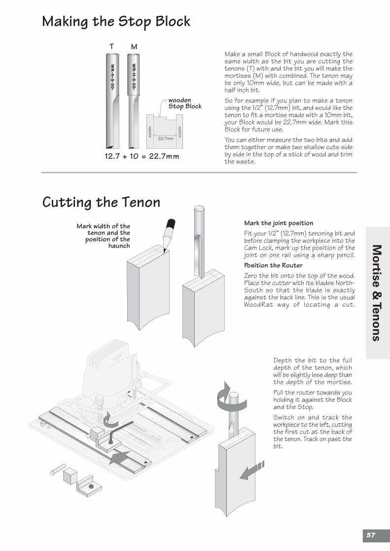
Making the Stop Block
Cutting the TenonMark width of the
tenon and theposition of the
haunch
Depth the bit to the fulldepth of the tenon, whichwill be slightly less deep thanthe depth of the mortise.Pull the router towards youholding it against the Blockand the Stop.Switch on and track theworkpiece to the left, cuttingthe first cut at the back ofthe tenon. Track on past thebit.
Make a small Block of hardwood exactly thesame width as the bit you are cutting thetenons (T) with and the bit you will make themortises (M) with combined. The tenon maybe only 10mm wide, but can be made with ahalf inch bit.So for example if you plan to make a tenonusing the 1/2” (12.7mm) bit, and would like thetenon to fit a mortise made with a 10mm bit,your Block would be 22.7mm wide. Mark thisBlock for future use.You can either measure the two bits and addthem together or make two shallow cuts sideby side in the top of a stick of wood and trimthe waste.
Mark the joint positionFit your 1/2” (12.7mm) tenoning bit andbefore clamping the workpiece into theCam Lock, mark up the position of thejoint on one rail using a sharp pencil.Position the RouterZero the bit onto the top of the wood.Place the cutter with its blades North-South so that the blade is exactlyagainst the back line. This is the usualWoodRat way of locating a cut.
12.7 + 10 = 22.7mm
woodenStop Block
MT
WR-H
-S-5
0-
WR-H
-S-5
0-
waste
waste
22.7mm
57
Mo
rtise & Ten
on
s

First unlock the router andraise it enough to put anacrylic depthing piece underthe depthing foot. Thedepthing piece is the samedepth as the groove that willlater take the panel. Here it is8mm deep.Lower the router onto thedepthing piece, and lock itsposition.The router is now raised by8mm (the thickness of theacrylic).Cut off the outside edge ofthe tenon to create thehaunch.The reason for this is to allowcover for the joint, when thewedges are driven home andthe horn is cut off.The first tenon is done. Nowcartwheel the rail and cut thetenon on the other end and soon for next rail.
Cutting the Haunch
Take out the Block.Bring the router forward tothe Stop.Hold the router forward andtrack the wood right, intothe bit to cut the front face.Take out the workpiece andtest the tenon.The first time you try, youmay need to adjust thewidth of the Block. You canreduce it by sanding orenlarge it with adhesive tape.
Cover
8mm
5588

Switch on and plunge the router.Track the wood to run the groove. Checkthat the groove runs straight through thetenon – exactly aligned. You can make thepass in two 4mm depthed stages.Note that if the rail is fairly long, you mayprefer to run the grooves by hand. Inwhich case, remove the clamps and userun it against Mortise Rail as a fence.The Brush can be clamped to the MortiseRail to give support if necessary.Run the groove in both rails .Repeat for both the stiles.The grooves runs around the inside face asa housing for the panel.
We now need a groove to fit the doorpanel.Place the Mortise Rail and make sure itsfirmly set.Clamp the top rail of the door up underthe plate.Change to the mortising 10mm straightbit.Zero the cutter onto the tenon anddepth it using the 8mm acrylic again.Don’t plunge it yet.Fix the top or bottom rail onto the MortiseRail as shown. Make sure that the correct(front) face is against the machine face. Thehaunches must face downwards.Locate the bit directly over the tenon and fixthe Router Plate with the Star Knob.
Ploughing the Groove
Marking out the MortisesPlace the pieces over the cupboardopening. Position the two stiles intheir final position and the top andbottom rails over the stiles.Pencil the positions of the tenons onthe face of the stiles and thentransfer them to the inner edge witha square.This tells you where the mortise goes.
59
Mo
rtise & Ten
on
s
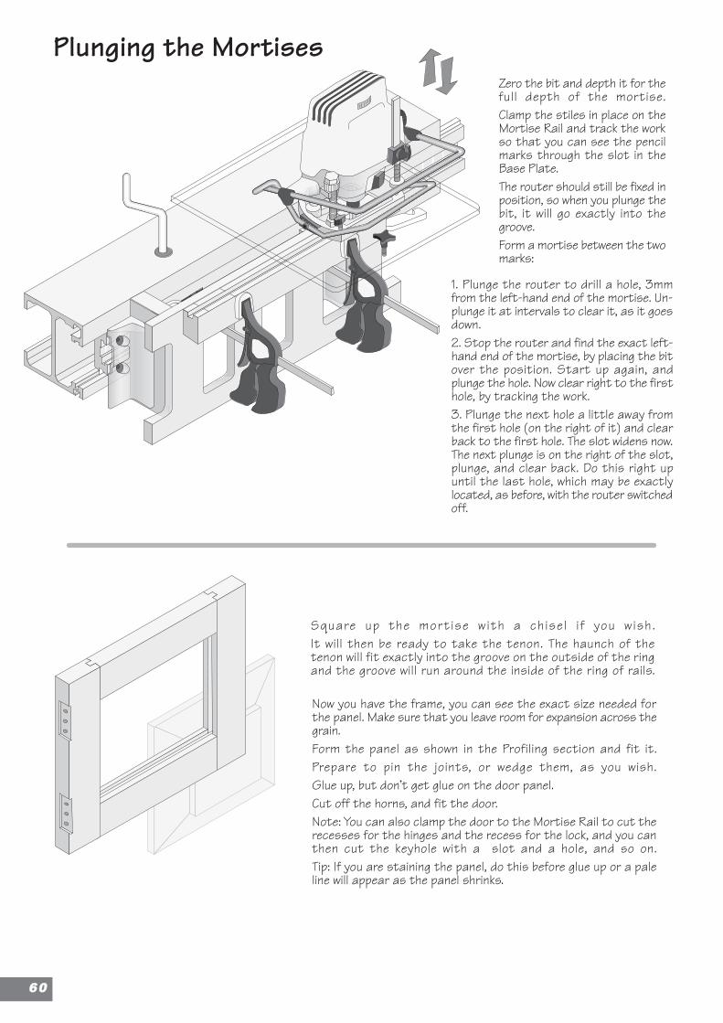
Plunging the Mortises
1. Plunge the router to drill a hole, 3mmfrom the left-hand end of the mortise. Un-plunge it at intervals to clear it, as it goesdown.2. Stop the router and find the exact left-hand end of the mortise, by placing the bitover the position. Start up again, andplunge the hole. Now clear right to the firsthole, by tracking the work.3. Plunge the next hole a little away fromthe first hole (on the right of it) and clearback to the first hole. The slot widens now.The next plunge is on the right of the slot,plunge, and clear back. Do this right upuntil the last hole, which may be exactlylocated, as before, with the router switchedoff.
Square up the mortise with a chisel i f you wish.It will then be ready to take the tenon. The haunch of thetenon will fit exactly into the groove on the outside of the ringand the groove will run around the inside of the ring of rails.
Now you have the frame, you can see the exact size needed forthe panel. Make sure that you leave room for expansion across thegrain.Form the panel as shown in the Profiling section and fit it.Prepare to pin the joints, or wedge them, as you wish.Glue up, but don’t get glue on the door panel.Cut off the horns, and fit the door.Note: You can also clamp the door to the Mortise Rail to cut therecesses for the hinges and the recess for the lock, and you canthen cut the keyhole with a slot and a hole, and so on.Tip: If you are staining the panel, do this before glue up or a paleline will appear as the panel shrinks.
Zero the bit and depth it for thefull depth of the mortise.Clamp the stiles in place on theMortise Rail and track the workso that you can see the pencilmarks through the slot in theBase Plate.The router should still be fixed inposition, so when you plunge thebit, it will go exactly into thegroove.Form a mortise between the twomarks:
6600
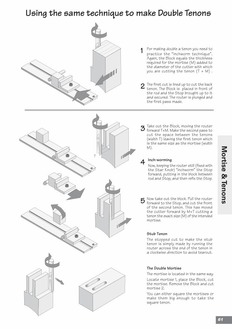
Stub TenonThe stopped cut to make the stubtenon is simply made by running therouter across the end of the tenon ina clockwise direction to avoid tearout.
The Double MortiseThe mortise is located in the same way.Locate mortise 1, place the Block, cutthe mortise. Remove the Block and cutmortise 2.You can either square the mortises ormake them big enough to take thesquare tenon.
1
2
3
4
5
For making double a tenon you need topractice the “inchworm technique”.Again, the Block equals the thicknessrequired for the mortise (M) added tothe diameter of the cutter with whichyou are cutting the tenon (T + M) .
The first cut is lined up to cut the backtenon. The Block is placed in front ofthe rod and the Stop brought up to itand secured. The router is plunged andthe first pass made.
Inch-wormingNow, keeping the router still (fixed withthe Star Knob) “inchworm” the Stopforward, putting in the block betweenrod and Stop, and then refix the Stop.
Using the same technique to make Double Tenons
Take out the Block, moving the routerforward T+M. Make the second pass tocut the space between the tenons(width T) leaving the first tenon whichis the same size as the mortise (widthM).
Now take out the block. Pull the routerforward to the Stop, and cut the frontof the second tenon. This has movedthe cutter forward by M+T cutting atenon the exact size (M) of the intendedmortise.
T
61
Mo
rtise & Ten
on
s
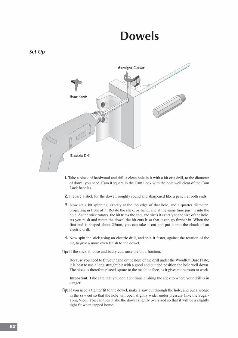
DowelsSet Up
1. Take a block of hardwood and drill a clean hole in it with a bit or a drill, to the diameterof dowel you need. Cam it square in the Cam Lock with the hole well clear of the CamLock handles.
2. Prepare a stick for the dowel, roughly round and sharpened like a pencil at both ends.
3. Now set a bit spinning, exactly at the top edge of that hole, and a quarter diameterprojecting in front of it. Rotate the stick, by hand, and at the same time push it into thehole. As the stick rotates, the bit trims the end, and sizes it exactly to the size of the hole.As you push and rotate the dowel the bit cuts it so that it can go further in. When thefirst end is shaped about 25mm, you can take it out and put it into the chuck of anelectric drill.
4. Now spin the stick using an electric drill, and spin it faster, against the rotation of thebit, to give a more even finish to the dowel.
Tip: If the stick is loose and badly cut, raise the bit a fraction.
Because you need to fit your hand or the nose of the drill under the WoodRat Base Plate,it is best to use a long straight bit with a good end cut and position the hole well down.The block is therefore placed square to the machine face, as it gives more room to work.
Important. Take care that you don’t continue pushing the stick to where your drill is indanger!
Tip: If you need a tighter fit to the dowel, make a saw cut through the hole, and put a wedgein the saw cut so that the hole will open slightly wider under pressure (like the Sugar-Tong Vice). You can then make the dowel slightly oversized so that it will be a slightlytight fit when tapped home.
Electric Drill
Straight Cutter
Star Knob
6622
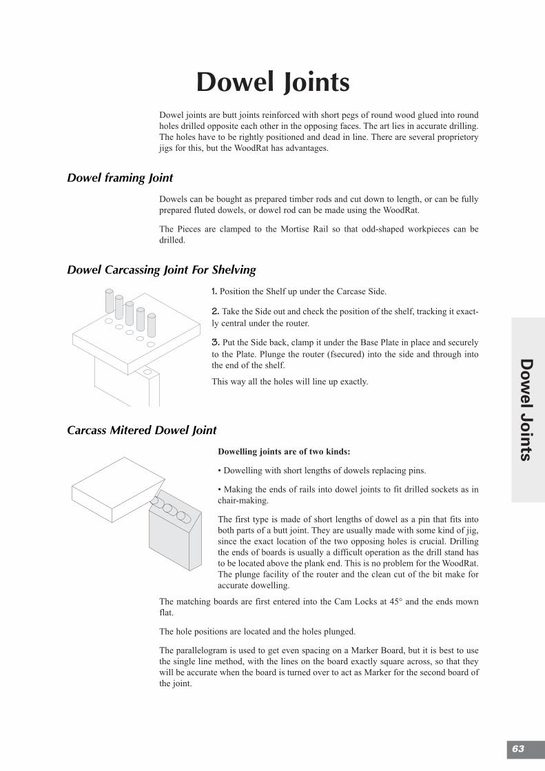
Dowel JointsDowel joints are butt joints reinforced with short pegs of round wood glued into roundholes drilled opposite each other in the opposing faces. The art lies in accurate drilling.The holes have to be rightly positioned and dead in line. There are several proprietoryjigs for this, but the WoodRat has advantages.
Dowel framing Joint
Dowels can be bought as prepared timber rods and cut down to length, or can be fullyprepared fluted dowels, or dowel rod can be made using the WoodRat.
The Pieces are clamped to the Mortise Rail so that odd-shaped workpieces can bedrilled.
Dowel Carcassing Joint For Shelving
1. Position the Shelf up under the Carcase Side.
2. Take the Side out and check the position of the shelf, tracking it exact-ly central under the router.
3. Put the Side back, clamp it under the Base Plate in place and securelyto the Plate. Plunge the router (fsecured) into the side and through intothe end of the shelf.
This way all the holes will line up exactly.
Carcass Mitered Dowel Joint
Dowelling joints are of two kinds:
• Dowelling with short lengths of dowels replacing pins.
• Making the ends of rails into dowel joints to fit drilled sockets as inchair-making.
The first type is made of short lengths of dowel as a pin that fits intoboth parts of a butt joint. They are usually made with some kind of jig,since the exact location of the two opposing holes is crucial. Drillingthe ends of boards is usually a difficult operation as the drill stand hasto be located above the plank end. This is no problem for the WoodRat.The plunge facility of the router and the clean cut of the bit make foraccurate dowelling.
The matching boards are first entered into the Cam Locks at 45° and the ends mownflat.
The hole positions are located and the holes plunged.
The parallelogram is used to get even spacing on a Marker Board, but it is best to usethe single line method, with the lines on the board exactly square across, so that theywill be accurate when the board is turned over to act as Marker for the second board ofthe joint.
63
Dow
el Join
ts

Notes
6644
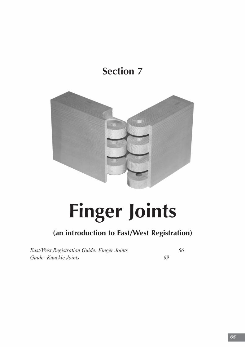
Section 7
Finger Joints(an introduction to East/West Registration)
East/West Registration Guide: Finger Joints 66Guide: Knuckle Joints 69
65
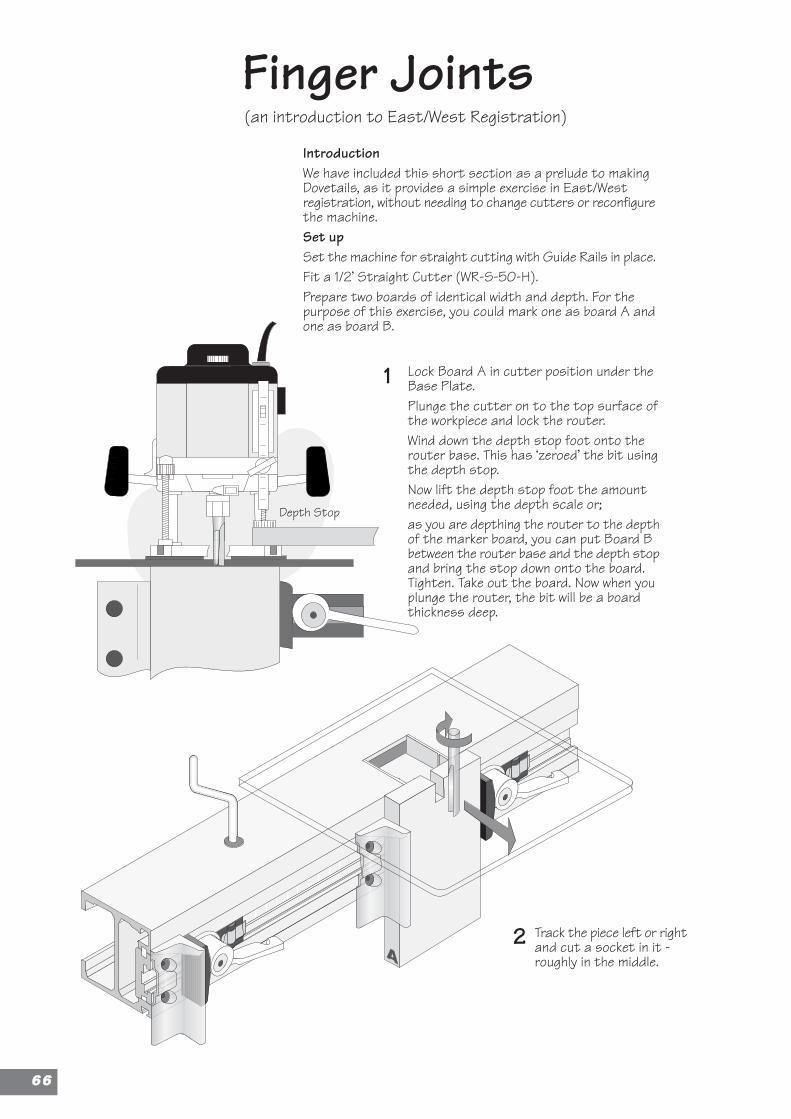
A
Finger JointsIntroductionWe have included this short section as a prelude to makingDovetails, as it provides a simple exercise in East/Westregistration, without needing to change cutters or reconfigurethe machine.Set upSet the machine for straight cutting with Guide Rails in place.Fit a 1/2’ Straight Cutter (WR-S-50-H).Prepare two boards of identical width and depth. For thepurpose of this exercise, you could mark one as board A andone as board B.
Depth Stop
(an introduction to East/West Registration)
Lock Board A in cutter position under theBase Plate.Plunge the cutter on to the top surface ofthe workpiece and lock the router.Wind down the depth stop foot onto therouter base. This has ‘zeroed’ the bit usingthe depth stop.Now lift the depth stop foot the amountneeded, using the depth scale or;as you are depthing the router to the depthof the marker board, you can put Board Bbetween the router base and the depth stopand bring the stop down onto the board.Tighten. Take out the board. Now when youplunge the router, the bit will be a boardthickness deep.
Track the piece left or rightand cut a socket in it -roughly in the middle.
1
2
6666
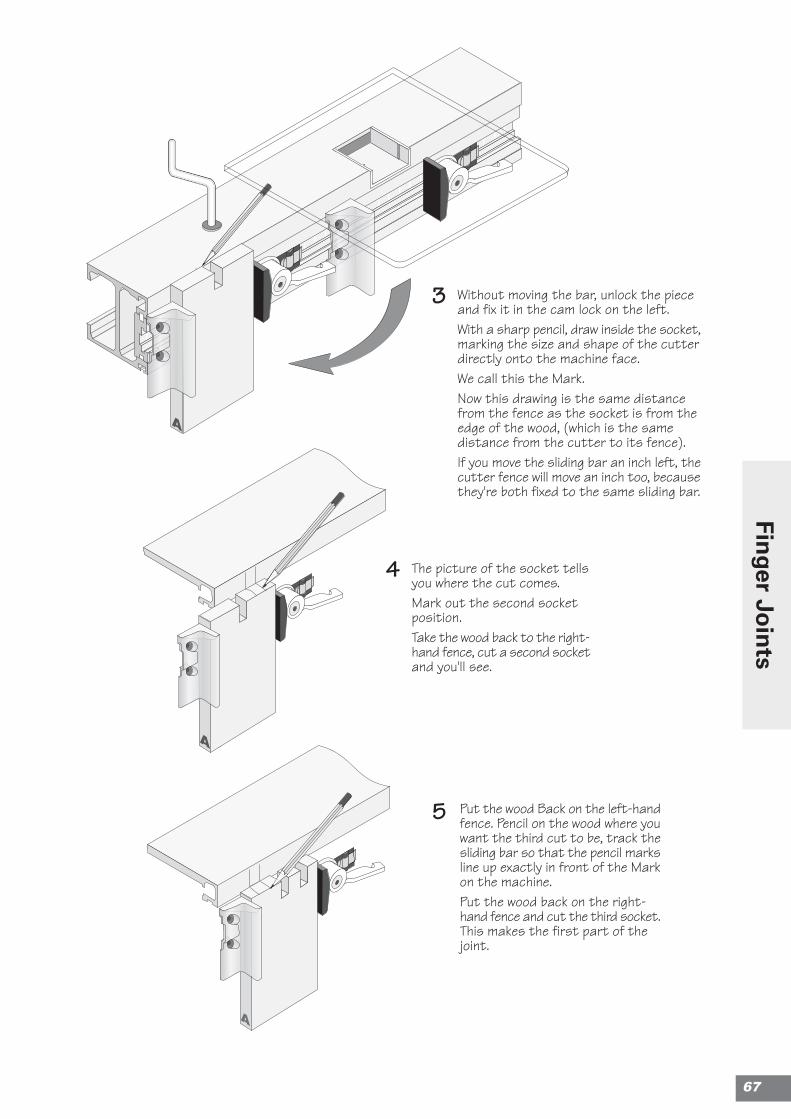
Without moving the bar, unlock the pieceand fix it in the cam lock on the left.With a sharp pencil, draw inside the socket,marking the size and shape of the cutterdirectly onto the machine face.We call this the Mark.Now this drawing is the same distancefrom the fence as the socket is from theedge of the wood, (which is the samedistance from the cutter to its fence).If you move the sliding bar an inch left, thecutter fence will move an inch too, becausethey're both fixed to the same sliding bar.
The picture of the socket tellsyou where the cut comes.Mark out the second socketposition.Take the wood back to the right-hand fence, cut a second socketand you'll see.
Put the wood Back on the left-handfence. Pencil on the wood where youwant the third cut to be, track thesliding bar so that the pencil marksline up exactly in front of the Markon the machine.Put the wood back on the right-hand fence and cut the third socket.This makes the first part of thejoint.
3
4
5
A
67
Finger Jo
ints
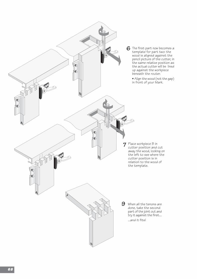
A
B
A
A
The first part now becomes atemplate for part two: thewood is aligned against thepencil picture of the cutter, inthe same relative position asthe actual cutter will be linedup against the workpiecebeneath the router.• Align the wood (not the gap)in front of your Mark.
Place workpiece B incutter position and cutaway the wood, looking onthe left to see where thecutter position is inrelation to the wood ofthe template.
When all the tenons aredone, take the secondpart of the joint out andtry it against the first.......and it fits!
B
6
9
7
B
6688
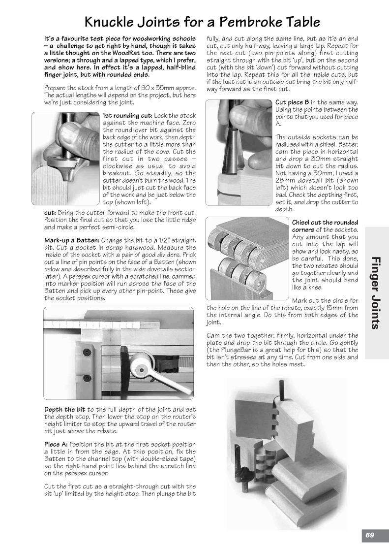
It’s a favourite test piece for woodworking schools– a challenge to get right by hand, though it takesa little thought on the WoodRat too. There are twoversions; a through and a lapped type, which I prefer,and show here. In effect it’s a lapped, half-blindfinger joint, but with rounded ends.
Prepare the stock from a length of 90 x 35mm approx.The actual lengths will depend on the project, but herewe’re just considering the joint.
1st rounding cut: Lock the stockagainst the machine face. Zerothe round-over bit against theback edge of the work, then depththe cutter to a little more thanthe radius of the cove. Cut thefirst cut in two passes –clockwise as usual to avoidbreakout. Go steadily, so thecutter doesn’t burn the wood. Thebit should just cut the back faceof the work and be just below thetop (shown left).
cut: Bring the cutter forward to make the front cut.Position the final cut so that you lose the little ridgeand make a perfect semi-circle.
Mark-up a Batten: Change the bit to a 1/2” straightbit. Cut a socket in scrap hardwood. Measure theinside of the socket with a pair of good dividers. Prickout a line of pin points on the face of a Batten (shownbelow and described fully in the wide dovetails sectionlater). A perspex cursor with a scratched line, cammedinto marker position will run across the face of theBatten and pick up every other pin-point. These givethe socket positions.
Depth the bit to the full depth of the joint and setthe depth stop. Then lower the stop on the router’sheight limiter to stop the upward travel of the routerbit just above the rebate.
Piece A: Position the bit at the first socket positiona little in from the edge. At this position, fix theBatten to the channel top (with double-sided tape)so the right-hand point lies behind the scratch lineon the perspex cursor.
Cut the first cut as a straight-through cut with thebit ‘up’ limited by the height stop. Then plunge the bit
fully, and cut along the same line, but as it’s an endcut, cut only half-way, leaving a large lap. Repeat forthe next cut (two pin-points along) first cuttingstraight through with the bit ‘up’, but on the secondcut (with the bit ‘down’) cut forward without cuttinginto the lap. Repeat this for all the inside cuts, butif the last cut is an outside cut bring the bit only half-way forward as the first cut.
Cut piece B in the same way.Using the points between thepoints that you used for pieceA.
The outside sockets can beradiused with a chisel. Better,cam the piece in horizontaland drop a 30mm straightbit down to cut the radius.Not having a 30mm, I used a28mm dovetail bit (shownleft) which doesn’t look toobad. Check the depthing first,set it, and drop the cutter todepth.
Chisel out the roundedcorners of the sockets.Any amount that youcut into the lap willshow and look nasty, sobe careful. This done,the two rebates shouldgo together cleanly andthe joint should bendlike a knee.
Mark out the circle forthe hole on the line of the rebate, exactly 15mm fromthe internal angle. Do this from both edges of thejoint.
Cam the two together, firmly, horizontal under theplate and drop the bit through the circle. Go gently(the PlungeBar is a great help for this) so that thebit isn’t stressed at any time. Cut from one side andthen the other, so the holes meet.
Knuckle Joints for a Pembroke Table
69
Finger Jo
ints

Notes
7700
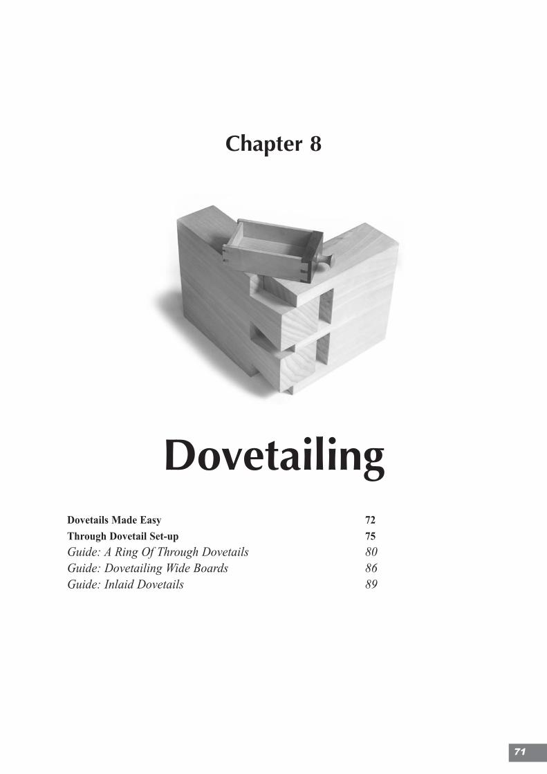
Chapter 8
DovetailingDovetails Made Easy 72
Through Dovetail Set-up 75
Guide: A Ring Of Through Dovetails 80Guide: Dovetailing Wide Boards 86Guide: Inlaid Dovetails 89
71
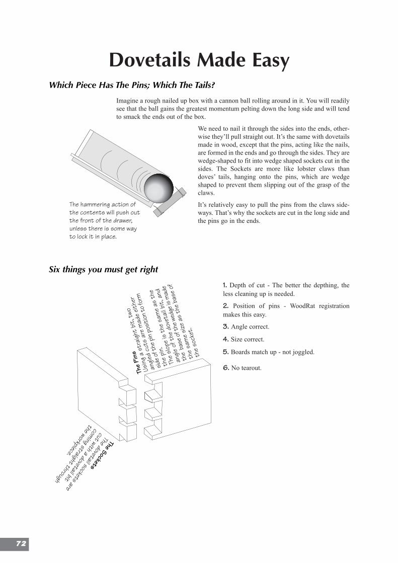
Dovetails Made EasyWhich Piece Has The Pins; Which The Tails?
Imagine a rough nailed up box with a cannon ball rolling around in it. You will readilysee that the ball gains the greatest momentum pelting down the long side and will tendto smack the ends out of the box.
We need to nail it through the sides into the ends, other-wise they’ll pull straight out. It’s the same with dovetailsmade in wood, except that the pins, acting like the nails,are formed in the ends and go through the sides. They arewedge-shaped to fit into wedge shaped sockets cut in thesides. The Sockets are more like lobster claws thandoves’ tails, hanging onto the pins, which are wedgeshaped to prevent them slipping out of the grasp of theclaws.
It’s relatively easy to pull the pins from the claws side-ways. That’s why the sockets are cut in the long side andthe pins go in the ends.
Six things you must get right
1. Depth of cut - The better the depthing, theless cleaning up is needed.
2. Position of pins - WoodRat registrationmakes this easy.
3. Angle correct.
4. Size correct.
5. Boards match up - not joggled.
6. No tearout.
Note that the triangle abc gives you theslope angle of the cutter: take the distanceac and see how many times it will go intothe distance ab. If it goes 61/2 times, thecutter slope is 1 in 6.5 and the slope numberis 6.5
f
thedistance d
a
b
ce
Make a second line in thetriangle for the second
drawer or set of legs
Lay the pieces together in theorientation they will be in when in thefinished piece. Draw a triangle onthem, pointing away from you.
You will then be able topick up any piece and tellwhere it comes from.
slope orangle
Neck
Shoulder
DiameterHalf Pin
Waste
Pitch or Spacing of sockets
Depth ofSocket
Tail
1:6 1:7 1:810°14°
WoodRat Range Handmade
10° 8°1:6 1:7
1:4.1
7°1:8
14°
1 2 3 4 5 6 7 8
Edge
of b
oard
1
Draw two lines with the try-squarean inch apart
The same cutter in differentstock thicknesses
Different cutters in differentthicknesses of stock
Remedy:First makea half cutto trim theedge, andthen thefull cut.
A cut, placed toonear the edge, cancause a ragged edge
This first (top left) hole is left without a rivet, whenthe grid is upside down.
Spar
Bartap down the rivet witha light hammer
bar
spar
hole in the workbench
The hammering action ofthe contents will push outthe front of the drawer,unless there is some wayto lock it in place.
The
Pins
Usin
g a
stra
ight
bit,
two
angl
ed c
uts
are
mad
e eit
her
side o
f the
pin
posit
ion to
form
the
pin.
The
slop
e is
the
sam
e as
the
angl
e of
the
dov
etai
l bit,
and
the
base
of t
he w
edge
is m
ade
the
sam
e si
ze a
s th
e ba
se o
f
the
sock
et.
The Sockets
The dovetail sockets are
cut with a dovetail bit
coming straight through
the workpiece.
Second Line
First Line
Third Line
First Position
Second Position
Third Position
7722
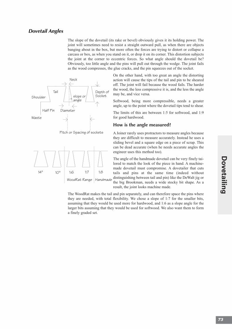
Dovetail Angles
The slope of the dovetail (its rake or bevel) obviously gives it its holding power. Thejoint will sometimes need to resist a straight outward pull, as when there are objectsbanging about in the box, but more often the forces are trying to distort or collapse acarcass or box, as when you stand on it, or drop it on its corner. This distortion subjectsthe joint at the corner to eccentric forces. So what angle should the dovetail be?Obviously, too little angle and the pins will pull out through the wedge. The joint failsas the wood compresses, the glue cracks, and the pin squeezes out of the socket.
On the other hand, with too great an angle the distortingaction will cause the tips of the tail and pin to be shearedoff. The joint will fail because the wood fails. The harderthe wood, the less compressive it is, and the less the anglemay be, and vice versa.
Softwood, being more compressible, needs a greaterangle, up to the point where the dovetail tips tend to shear.
The limits of this are between 1:5 for softwood, and 1:9for good hardwood.
How is the angle measured?
A Joiner rarely uses protractors to measure angles becausethey are difficult to measure accurately. Instead he uses asliding bevel and a square edge on a piece of scrap. Thiscan be dead accurate (when he needs accurate angles theengineer uses this method too).
The angle of the handmade dovetail can be very finely tai-lored to match the look of the piece in hand. A machine-made dovetail must compromise. A dovetailer that cutstails and pins at the same time (indeed withoutdistinguishing between tail and pin) like the DeWalt jig orthe big Brookman, needs a wide stocky bit shape. As aresult, the joint looks machine made.
The WoodRat makes the tail and pin separately, and can therefore space the pins wherethey are needed, with total flexibility. We chose a slope of 1:7 for the smaller bits,assuming that they would be used more for hardwood, and 1:6 as a slope angle for thelarger bits assuming that they would be used for softwood. We also want them to forma finely graded set.
Note that the triangle abc gives you theslope angle of the cutter: take the distanceac and see how many times it will go intothe distance ab. If it goes 61/2 times, thecutter slope is 1 in 6.5 and the slope numberis 6.5
f
thedistance d
a
b
ce
Make a second line in thetriangle for the second
drawer or set of legs
Lay the pieces together in theorientation they will be in when in thefinished piece. Draw a triangle onthem, pointing away from you.
You will then be able topick up any piece and tellwhere it comes from.
slope orangle
Neck
Shoulder
DiameterHalf Pin
Waste
Pitch or Spacing of sockets
Depth ofSocket
Tail
1:6 1:7 1:810°14°
WoodRat Range Handmade
10° 8°1:6 1:7
1:4.1
7°1:8
14°
1 2 3 4 5 6 7 8
Edge
of b
oard
1
Draw two lines with the try-squarean inch apart
The same cutter in differentstock thicknesses
Different cutters in differentthicknesses of stock
Remedy:First makea half cutto trim theedge, andthen thefull cut.
A cut, placed toonear the edge, cancause a ragged edge
This first (top left) hole is left without a rivet, whenthe grid is upside down.
Spar
Bartap down the rivet witha light hammer
bar
spar
hole in the workbench
The hammering action ofthe contents will push outthe front of the drawer,unless there is some wayto lock it in place.
The
Pins
Usin
g a
stra
ight
bit,
two
angl
ed c
uts
are
mad
e eit
her
side o
f the
pin
posit
ion to
form
the
pin.
The
slop
e is
the
sam
e as
the
angl
e of
the
dov
etai
l bit,
and
the
base
of t
he w
edge
is m
ade
the
sam
e si
ze a
s th
e ba
se o
f
the
sock
et.
The Sockets
The dovetail sockets are
cut with a dovetail bit
coming straight through
the workpiece.
Second Line
First Line
Third Line
First Position
Second Position
Third Position
73
Dovetailin
g
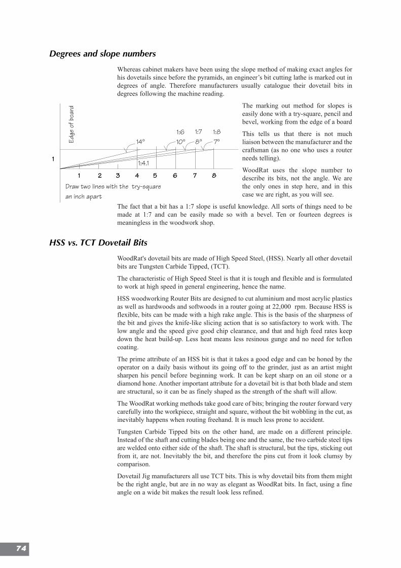
Degrees and slope numbers
Whereas cabinet makers have been using the slope method of making exact angles forhis dovetails since before the pyramids, an engineer’s bit cutting lathe is marked out indegrees of angle. Therefore manufacturers usually catalogue their dovetail bits indegrees following the machine reading.
The marking out method for slopes iseasily done with a try-square, pencil andbevel, working from the edge of a board
This tells us that there is not muchliaison between the manufacturer and thecraftsman (as no one who uses a routerneeds telling).
WoodRat uses the slope number todescribe its bits, not the angle. We arethe only ones in step here, and in thiscase we are right, as you will see.
The fact that a bit has a 1:7 slope is useful knowledge. All sorts of things need to bemade at 1:7 and can be easily made so with a bevel. Ten or fourteen degrees ismeaningless in the woodwork shop.
HSS vs. TCT Dovetail Bits
WoodRat's dovetail bits are made of High Speed Steel, (HSS). Nearly all other dovetailbits are Tungsten Carbide Tipped, (TCT).
The characteristic of High Speed Steel is that it is tough and flexible and is formulatedto work at high speed in general engineering, hence the name.
HSS woodworking Router Bits are designed to cut aluminium and most acrylic plasticsas well as hardwoods and softwoods in a router going at 22,000 rpm. Because HSS isflexible, bits can be made with a high rake angle. This is the basis of the sharpness ofthe bit and gives the knife-like slicing action that is so satisfactory to work with. Thelow angle and the speed give good chip clearance, and that and high feed rates keepdown the heat build-up. Less heat means less resinous gunge and no need for tefloncoating.
The prime attribute of an HSS bit is that it takes a good edge and can be honed by theoperator on a daily basis without its going off to the grinder, just as an artist mightsharpen his pencil before beginning work. It can be kept sharp on an oil stone or adiamond hone. Another important attribute for a dovetail bit is that both blade and stemare structural, so it can be as finely shaped as the strength of the shaft will allow.
The WoodRat working methods take good care of bits; bringing the router forward verycarefully into the workpiece, straight and square, without the bit wobbling in the cut, asinevitably happens when routing freehand. It is much less prone to accident.
Tungsten Carbide Tipped bits on the other hand, are made on a different principle.Instead of the shaft and cutting blades being one and the same, the two carbide steel tipsare welded onto either side of the shaft. The shaft is structural, but the tips, sticking outfrom it, are not. Inevitably the bit, and therefore the pins cut from it look clumsy bycomparison.
Dovetail Jig manufacturers all use TCT bits. This is why dovetail bits from them mightbe the right angle, but are in no way as elegant as WoodRat bits. In fact, using a fineangle on a wide bit makes the result look less refined.
Note that the triangle abc gives you theslope angle of the cutter: take the distanceac and see how many times it will go intothe distance ab. If it goes 61/2 times, thecutter slope is 1 in 6.5 and the slope numberis 6.5
f
thedistance d
a
b
ce
Make a second line in thetriangle for the second
drawer or set of legs
Lay the pieces together in theorientation they will be in when in thefinished piece. Draw a triangle onthem, pointing away from you.
You will then be able topick up any piece and tellwhere it comes from.
slope orangle
Neck
Shoulder
DiameterHalf Pin
Waste
Pitch or Spacing of sockets
Depth ofSocket
Tail
1:6 1:7 1:810°14°
WoodRat Range Handmade
10° 8°1:6 1:7
1:4.1
7°1:8
14°
1 2 3 4 5 6 7 8
Edge
of b
oard
1
Draw two lines with the try-squarean inch apart
The same cutter in differentstock thicknesses
Different cutters in differentthicknesses of stock
Remedy:First makea half cutto trim theedge, andthen thefull cut.
A cut, placed toonear the edge, cancause a ragged edge
This first (top left) hole is left without a rivet, whenthe grid is upside down.
Spar
Bartap down the rivet witha light hammer
bar
spar
hole in the workbench
The hammering action ofthe contents will push outthe front of the drawer,unless there is some wayto lock it in place.
The
Pins
Usin
g a
stra
ight
bit,
two
angl
ed c
uts
are
mad
e eit
her
side o
f the
pin
posit
ion to
form
the
pin.
The
slop
e is
the
sam
e as
the
angl
e of
the
dov
etai
l bit,
and
the
base
of t
he w
edge
is m
ade
the
sam
e si
ze a
s th
e ba
se o
f
the
sock
et.
The Sockets
The dovetail sockets are
cut with a dovetail bit
coming straight through
the workpiece.
Second Line
First Line
Third Line
First Position
Second Position
Third Position
7744
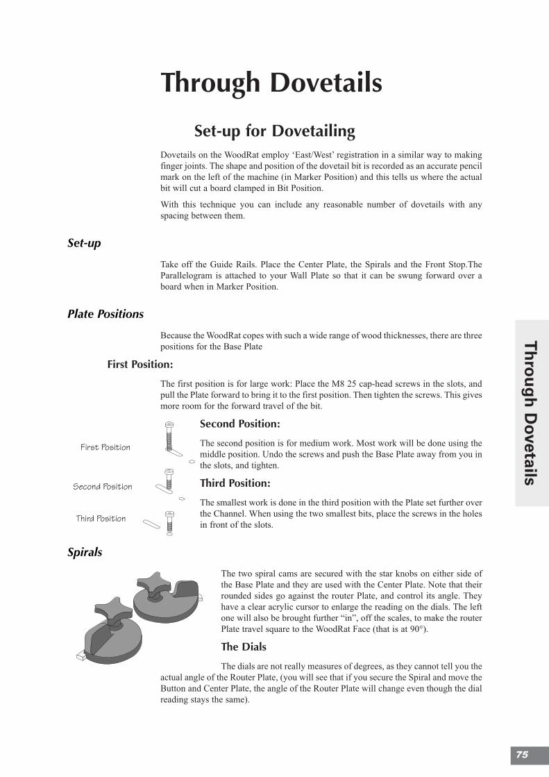
Through Dovetails
Set-up for DovetailingDovetails on the WoodRat employ ‘East/West’ registration in a similar way to makingfinger joints. The shape and position of the dovetail bit is recorded as an accurate pencilmark on the left of the machine (in Marker Position) and this tells us where the actualbit will cut a board clamped in Bit Position.
With this technique you can include any reasonable number of dovetails with anyspacing between them.
Set-up
Take off the Guide Rails. Place the Center Plate, the Spirals and the Front Stop.TheParallelogram is attached to your Wall Plate so that it can be swung forward over aboard when in Marker Position.
Plate Positions
Because the WoodRat copes with such a wide range of wood thicknesses, there are threepositions for the Base Plate
First Position:
The first position is for large work: Place the M8 25 cap-head screws in the slots, andpull the Plate forward to bring it to the first position. Then tighten the screws. This givesmore room for the forward travel of the bit.
Second Position:
The second position is for medium work. Most work will be done using themiddle position. Undo the screws and push the Base Plate away from you inthe slots, and tighten.
Third Position:
The smallest work is done in the third position with the Plate set further overthe Channel. When using the two smallest bits, place the screws in the holesin front of the slots.
Spirals
The two spiral cams are secured with the star knobs on either side ofthe Base Plate and they are used with the Center Plate. Note that theirrounded sides go against the router Plate, and control its angle. Theyhave a clear acrylic cursor to enlarge the reading on the dials. The leftone will also be brought further “in”, off the scales, to make the routerPlate travel square to the WoodRat Face (that is at 90°).
The Dials
The dials are not really measures of degrees, as they cannot tell you theactual angle of the Router Plate, (you will see that if you secure the Spiral and move theButton and Center Plate, the angle of the Router Plate will change even though the dialreading stays the same).
Note that the triangle abc gives you theslope angle of the cutter: take the distanceac and see how many times it will go intothe distance ab. If it goes 61/2 times, thecutter slope is 1 in 6.5 and the slope numberis 6.5
f
thedistance d
a
b
ce
Make a second line in thetriangle for the second
drawer or set of legs
Lay the pieces together in theorientation they will be in when in thefinished piece. Draw a triangle onthem, pointing away from you.
You will then be able topick up any piece and tellwhere it comes from.
slope orangle
Neck
Shoulder
DiameterHalf Pin
Waste
Pitch or Spacing of sockets
Depth ofSocket
Tail
1:6 1:7 1:810°14°
WoodRat Range Handmade
10° 8°1:6 1:7
1:4.1
7°1:8
14°
1 2 3 4 5 6 7 8
Edge
of b
oard
1
Draw two lines with the try-squarean inch apart
The same cutter in differentstock thicknesses
Different cutters in differentthicknesses of stock
Remedy:First makea half cutto trim theedge, andthen thefull cut.
A cut, placed toonear the edge, cancause a ragged edge
This first (top left) hole is left without a rivet, whenthe grid is upside down.
Spar
Bartap down the rivet witha light hammer
bar
spar
hole in the workbench
The hammering action ofthe contents will push outthe front of the drawer,unless there is some wayto lock it in place.
The
Pins
Usin
g a
stra
ight
bit,
two
angl
ed c
uts
are
mad
e eit
her
side o
f the
pin
posit
ion to
form
the
pin.
The
slop
e is
the
sam
e as
the
angl
e of
the
dov
etai
l bit,
and
the
base
of t
he w
edge
is m
ade
the
sam
e si
ze a
s th
e ba
se o
f
the
sock
et.
The Sockets
The dovetail sockets are
cut with a dovetail bit
coming straight through
the workpiece.
Second Line
First Line
Third Line
First Position
Second Position
Third Position
75
Th
rou
gh
Dovetails
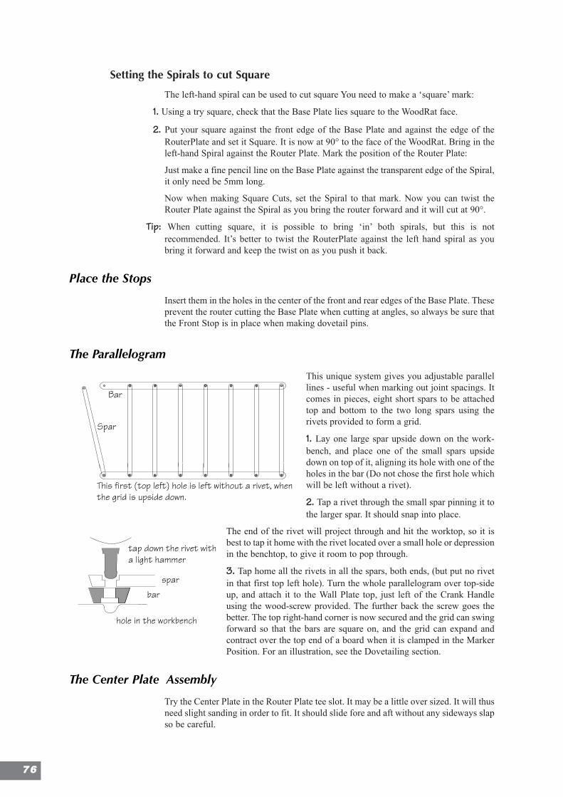
Setting the Spirals to cut Square
The left-hand spiral can be used to cut square You need to make a ‘square’ mark:
1. Using a try square, check that the Base Plate lies square to the WoodRat face.
2. Put your square against the front edge of the Base Plate and against the edge of theRouterPlate and set it Square. It is now at 90° to the face of the WoodRat. Bring in theleft-hand Spiral against the Router Plate. Mark the position of the Router Plate:
Just make a fine pencil line on the Base Plate against the transparent edge of the Spiral,it only need be 5mm long.
Now when making Square Cuts, set the Spiral to that mark. Now you can twist theRouter Plate against the Spiral as you bring the router forward and it will cut at 90°.
Tip: When cutting square, it is possible to bring ‘in’ both spirals, but this is notrecommended. It’s better to twist the RouterPlate against the left hand spiral as youbring it forward and keep the twist on as you push it back.
Place the Stops
Insert them in the holes in the center of the front and rear edges of the Base Plate. Theseprevent the router cutting the Base Plate when cutting at angles, so always be sure thatthe Front Stop is in place when making dovetail pins.
The Parallelogram
This unique system gives you adjustable parallellines - useful when marking out joint spacings. Itcomes in pieces, eight short spars to be attachedtop and bottom to the two long spars using therivets provided to form a grid.
1. Lay one large spar upside down on the work-bench, and place one of the small spars upsidedown on top of it, aligning its hole with one of theholes in the bar (Do not chose the first hole whichwill be left without a rivet).
2. Tap a rivet through the small spar pinning it tothe larger spar. It should snap into place.
The end of the rivet will project through and hit the worktop, so it isbest to tap it home with the rivet located over a small hole or depressionin the benchtop, to give it room to pop through.
3. Tap home all the rivets in all the spars, both ends, (but put no rivetin that first top left hole). Turn the whole parallelogram over top-sideup, and attach it to the Wall Plate top, just left of the Crank Handleusing the wood-screw provided. The further back the screw goes thebetter. The top right-hand corner is now secured and the grid can swingforward so that the bars are square on, and the grid can expand andcontract over the top end of a board when it is clamped in the MarkerPosition. For an illustration, see the Dovetailing section.
The Center Plate Assembly
Try the Center Plate in the Router Plate tee slot. It may be a little over sized. It will thusneed slight sanding in order to fit. It should slide fore and aft without any sideways slapso be careful.
Note that the triangle abc gives you theslope angle of the cutter: take the distanceac and see how many times it will go intothe distance ab. If it goes 61/2 times, thecutter slope is 1 in 6.5 and the slope numberis 6.5
f
thedistance d
a
b
ce
Make a second line in thetriangle for the second
drawer or set of legs
Lay the pieces together in theorientation they will be in when in thefinished piece. Draw a triangle onthem, pointing away from you.
You will then be able topick up any piece and tellwhere it comes from.
slope orangle
Neck
Shoulder
DiameterHalf Pin
Waste
Pitch or Spacing of sockets
Depth ofSocket
Tail
1:6 1:7 1:810°14°
WoodRat Range Handmade
10° 8°1:6 1:7
1:4.1
7°1:8
14°
1 2 3 4 5 6 7 8
Edge
of b
oard
1
Draw two lines with the try-squarean inch apart
The same cutter in differentstock thicknesses
Different cutters in differentthicknesses of stock
Remedy:First makea half cutto trim theedge, andthen thefull cut.
A cut, placed toonear the edge, cancause a ragged edge
This first (top left) hole is left without a rivet, whenthe grid is upside down.
Spar
Bartap down the rivet witha light hammer
bar
spar
hole in the workbench
The hammering action ofthe contents will push outthe front of the drawer,unless there is some wayto lock it in place.
The
Pins
Usin
g a
stra
ight
bit,
two
angl
ed c
uts
are
mad
e eit
her
side o
f the
pin
posit
ion to
form
the
pin.
The
slop
e is
the
sam
e as
the
angl
e of
the
dov
etai
l bit,
and
the
base
of t
he w
edge
is m
ade
the
sam
e si
ze a
s th
e ba
se o
f
the
sock
et.
The Sockets
The dovetail sockets are
cut with a dovetail bit
coming straight through
the workpiece.
Second Line
First Line
Third Line
First Position
Second Position
Third Position
7766
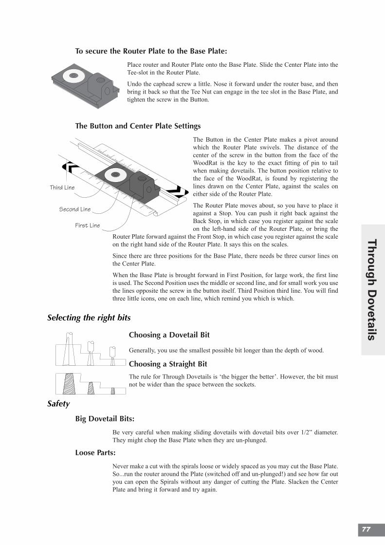
To secure the Router Plate to the Base Plate:
Place router and Router Plate onto the Base Plate. Slide the Center Plate into theTee-slot in the Router Plate.
Undo the caphead screw a little. Nose it forward under the router base, and thenbring it back so that the Tee Nut can engage in the tee slot in the Base Plate, andtighten the screw in the Button.
The Button and Center Plate Settings
The Button in the Center Plate makes a pivot aroundwhich the Router Plate swivels. The distance of thecenter of the screw in the button from the face of theWoodRat is the key to the exact fitting of pin to tailwhen making dovetails. The button position relative tothe face of the WoodRat, is found by registering thelines drawn on the Center Plate, against the scales oneither side of the Router Plate.
The Router Plate moves about, so you have to place itagainst a Stop. You can push it right back against theBack Stop, in which case you register against the scaleon the left-hand side of the Router Plate, or bring the
Router Plate forward against the Front Stop, in which case you register against the scaleon the right hand side of the Router Plate. It says this on the scales.
Since there are three positions for the Base Plate, there needs be three cursor lines onthe Center Plate.
When the Base Plate is brought forward in First Position, for large work, the first lineis used. The Second Position uses the middle or second line, and for small work you usethe lines opposite the screw in the button itself. Third Position third line. You will findthree little icons, one on each line, which remind you which is which.
Selecting the right bits
Choosing a Dovetail Bit
Generally, you use the smallest possible bit longer than the depth of wood.
Choosing a Straight Bit
The rule for Through Dovetails is ‘the bigger the better’. However, the bit mustnot be wider than the space between the sockets.
Safety
Big Dovetail Bits:
Be very careful when making sliding dovetails with dovetail bits over 1/2” diameter.They might chop the Base Plate when they are un-plunged.
Loose Parts:
Never make a cut with the spirals loose or widely spaced as you may cut the Base Plate.So...run the router around the Plate (switched off and un-plunged!) and see how far outyou can open the Spirals without any danger of cutting the Plate. Slacken the CenterPlate and bring it forward and try again.
The same cutter in Different cutters in
Note that the triangle abc gives you theslope angle of the cutter: take the distanceac and see how many times it will go intothe distance ab. If it goes 61/2 times, thecutter slope is 1 in 6.5 and the slope numberis 6.5
f
thedistance d
a
b
ce
Make a second line in thetriangle for the second
drawer or set of legs
Lay the pieces together in theorientation they will be in when in thefinished piece. Draw a triangle onthem, pointing away from you.
You will then be able topick up any piece and tellwhere it comes from.
slope orangle
Neck
Shoulder
DiameterHalf Pin
Waste
Pitch or Spacing of sockets
Depth ofSocket
Tail
1:6 1:7 1:810°14°
WoodRat Range Handmade
10° 8°1:6 1:7
1:4.1
7°1:8
14°
1 2 3 4 5 6 7 8
Edge
of b
oard
1
Draw two lines with the try-squarean inch apart
The same cutter in differentstock thicknesses
Different cutters in differentthicknesses of stock
Remedy:First makea half cutto trim theedge, andthen thefull cut.
A cut, placed toonear the edge, cancause a ragged edge
This first (top left) hole is left without a rivet, whenthe grid is upside down.
Spar
Bartap down the rivet witha light hammer
bar
spar
hole in the workbench
The hammering action ofthe contents will push outthe front of the drawer,unless there is some wayto lock it in place.
The
Pins
Usin
g a
stra
ight
bit,
two
angl
ed c
uts
are
mad
e eit
her
side o
f the
pin
posit
ion to
form
the
pin.
The
slop
e is
the
sam
e as
the
angl
e of
the
dov
etai
l bit,
and
the
base
of t
he w
edge
is m
ade
the
sam
e si
ze a
s th
e ba
se o
f
the
sock
et.
The Sockets
The dovetail sockets are
cut with a dovetail bit
coming straight through
the workpiece.
Second Line
First Line
Third Line
First Position
Second Position
Third Position
First Position
Second Position
Third Position
This first (top left) hole is left withouta rivet, when the grid is upside down.
spar
bar
tapdown the rivetwith a light hammer
barspar
hole in the workbench
RaisingPlates
identifying parts
Second Line
First Line
Third Line
77
Th
rou
gh
Dovetails
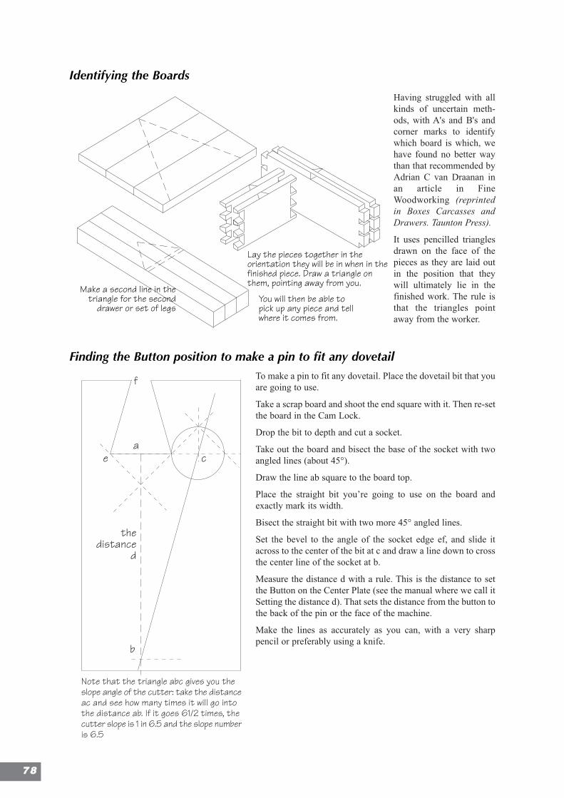
Identifying the Boards
Having struggled with allkinds of uncertain meth-ods, with A's and B's andcorner marks to identifywhich board is which, wehave found no better waythan that recommended byAdrian C van Draanan inan article in FineWoodworking (reprintedin Boxes Carcasses andDrawers. Taunton Press).
It uses pencilled trianglesdrawn on the face of thepieces as they are laid outin the position that theywill ultimately lie in thefinished work. The rule isthat the triangles pointaway from the worker.
Finding the Button position to make a pin to fit any dovetailTo make a pin to fit any dovetail. Place the dovetail bit that youare going to use.
Take a scrap board and shoot the end square with it. Then re-setthe board in the Cam Lock.
Drop the bit to depth and cut a socket.
Take out the board and bisect the base of the socket with twoangled lines (about 45°).
Draw the line ab square to the board top.
Place the straight bit you’re going to use on the board andexactly mark its width.
Bisect the straight bit with two more 45° angled lines.
Set the bevel to the angle of the socket edge ef, and slide itacross to the center of the bit at c and draw a line down to crossthe center line of the socket at b.
Measure the distance d with a rule. This is the distance to setthe Button on the Center Plate (see the manual where we call itSetting the distance d). That sets the distance from the button tothe back of the pin or the face of the machine.
Make the lines as accurately as you can, with a very sharppencil or preferably using a knife.
Note that the triangle abc gives you theslope angle of the cutter: take the distanceac and see how many times it will go intothe distance ab. If it goes 61/2 times, thecutter slope is 1 in 6.5 and the slope numberis 6.5
f
thedistance
d
a
b
ce
Note that the triangle abc gives you theslope angle of the cutter: take the distanceac and see how many times it will go intothe distance ab. If it goes 61/2 times, thecutter slope is 1 in 6.5 and the slope numberis 6.5
f
thedistance d
a
b
ce
Make a second line in thetriangle for the second
drawer or set of legs
Lay the pieces together in theorientation they will be in when in thefinished piece. Draw a triangle onthem, pointing away from you.
You will then be able topick up any piece and tellwhere it comes from.
slope orangle
Neck
Shoulder
DiameterHalf Pin
Waste
Pitch or Spacing of sockets
Depth ofSocket
Tail
1:6 1:7 1:810°14°
WoodRat Range Handmade
10° 8°1:6 1:7
1:4.1
7°1:8
14°
1 2 3 4 5 6 7 8
Edge
of b
oard
1
Draw two lines with the try-squarean inch apart
The same cutter in differentstock thicknesses
Different cutters in differentthicknesses of stock
Remedy:First makea half cutto trim theedge, andthen thefull cut.
A cut, placed toonear the edge, cancause a ragged edge
This first (top left) hole is left without a rivet, whenthe grid is upside down.
Spar
Bartap down the rivet witha light hammer
bar
spar
hole in the workbench
The hammering action ofthe contents will push outthe front of the drawer,unless there is some wayto lock it in place.
The
Pins
Usin
g a
stra
ight
bit,
two
angl
ed c
uts
are
mad
e eit
her
side o
f the
pin
posit
ion to
form
the
pin.
The
slop
e is
the
sam
e as
the
angl
e of
the
dov
etai
l bit,
and
the
base
of t
he w
edge
is m
ade
the
sam
e si
ze a
s th
e ba
se o
f
the
sock
et.
The Sockets
The dovetail sockets are
cut with a dovetail bit
coming straight through
the workpiece.
Second Line
First Line
Third Line
First Position
Second Position
Third Position
7788
Avoiding Tearout
One Way
Fine grained hardwoods will give very little tearout, but if you are getting splinters asthe bit comes through the board, there is a simple remedy that takes less time than plan-ing up the finished work. At each pin position, pre-cut the front of the board by cuttinga right and a left -hand cut into the board from the front, and then clear to the left, acrossthe board front between the pins. Push the bit in just less than half a diameter. Whenyou come round from behind the board to cut the pin, there will be nothing to break out,and the joint will be as clean as a whistle.
Another way:
Cut a right-hand cut half way into the wood coming from behind. Then, un-plunge, andhop the router over to the front of the board and push into the board to joint the cuts.This is easy with a PlungeBar.
Cleaning up
Tip: The more accurate the depthing, the less time is spent cleaning up after gluing up.
Dovetails and finger joints properly prepared and cut on the WoodRat can usually beglued together with only a little light clamping, but it’s wise to make pins a whiskershort so that the face stands slightly proud of the pins. When the box is clamped, therewill be no damage to the pins and there is no need for those tedious cut-out clampingblocks. The sides are planed down to the pin ends and this removes any tearout.
Getting the depthing correct, therefore, means a welcome saving in cleaning-up time.It’s well worthwhile getting good at depthing the bit and also, incidentally, shellackingthe parts that you don't want glue stuck into, such as the inner faces of drawers.
Heavy Timber
With its ability to dovetail 2” timber, the WoodRat is robust enough to make a log cabin.Heavy section timber is treated generally in the same way as smaller stuff, but greaterattention to firmness is needed.
A 2 horsepower motor capable of taking a 1/2” shank bit will handle boards up to 2”thick. For boards over 7/8” place one or more Raising Plates under the Base Plate, togain greater depth of cut. Use the longer caphead screws to hold the Base Plate.
If greater forward clearance is needed, bring the Base Plate to Position3, (forward in itsslots). When making big dovetails you will need to register the front line on the CenterPlate on the right hand silver scale on the Router Plate, when the Router Plate is broughtforward onto the Front Stop. You then use the front cursor.
Extreme care must be taken for larger sections, especially in hardwood. Keep the bitsvery sharp, and if necessary take out waste in sections, a little at a time. leaving a finalfine cut on the line and to the exact depth.
But, always cut dovetails in one pass.
The ability to work 2” timber is particularly useful when framing up 2”x3”s and 2”x4”s.The framework can be jointed and erected, and the secondary fixings can be done on it,(cross bracing and window fitting etc.) before it is finally knocked down and glued up,or screwed together.
79
Th
rou
gh
Dovetails
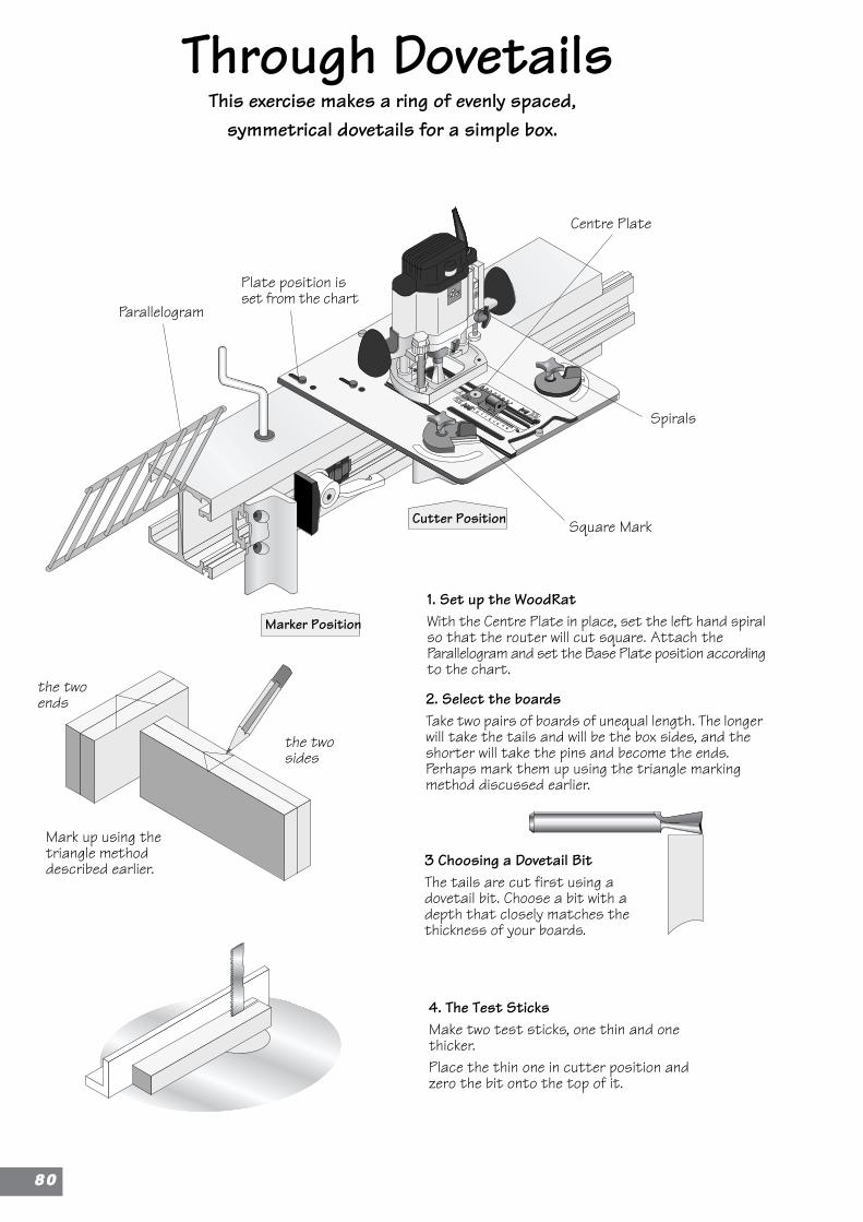
Through Dovetails
Plate position isset from the chart
4. The Test SticksMake two test sticks, one thin and onethicker.Place the thin one in cutter position andzero the bit onto the top of it.
This exercise makes a ring of evenly spaced,symmetrical dovetails for a simple box.
2. Select the boardsTake two pairs of boards of unequal length. The longerwill take the tails and will be the box sides, and theshorter will take the pins and become the ends.Perhaps mark them up using the triangle markingmethod discussed earlier.
1. Set up the WoodRatWith the Centre Plate in place, set the left hand spiralso that the router will cut square. Attach theParallelogram and set the Base Plate position accordingto the chart.
3 Choosing a Dovetail BitThe tails are cut first using adovetail bit. Choose a bit with adepth that closely matches thethickness of your boards.
Mark up using thetriangle methoddescribed earlier.
the twoends
the twosides
Cutter Position
Marker Position
Square Mark
Parallelogram
Centre Plate
Spirals
8800
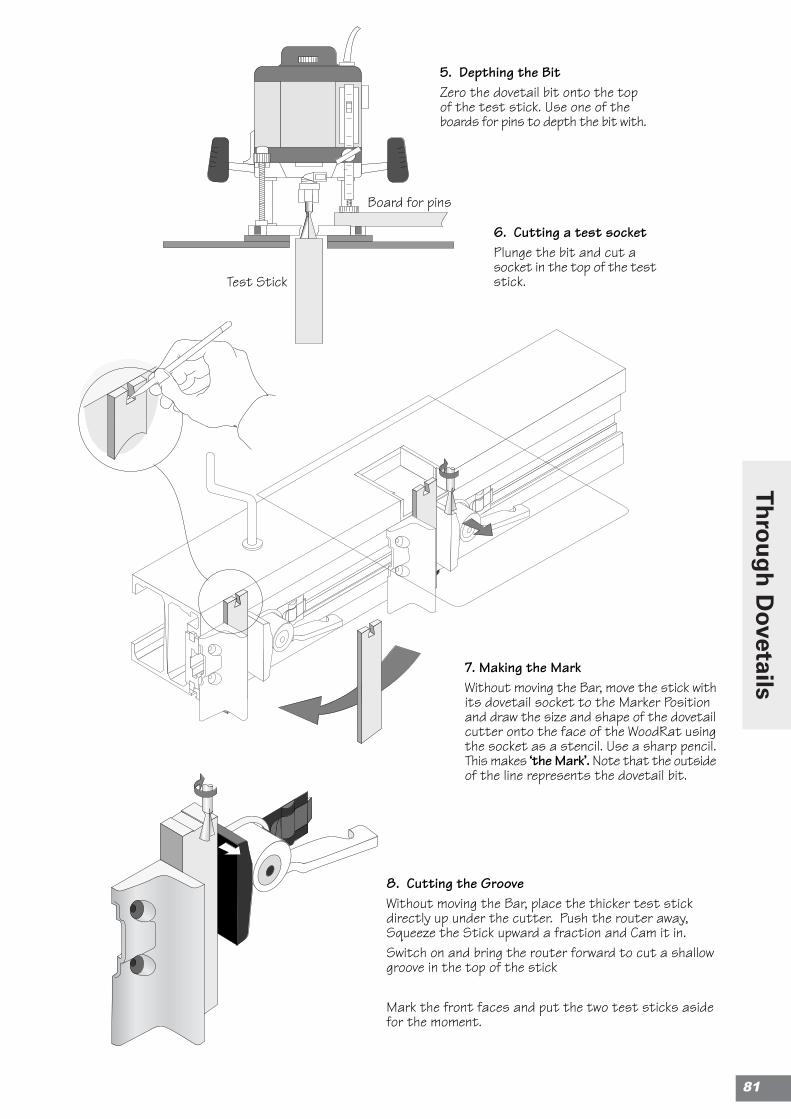
Test Stick
Board for pins
6. Cutting a test socketPlunge the bit and cut asocket in the top of the teststick.
5. Depthing the BitZero the dovetail bit onto the topof the test stick. Use one of theboards for pins to depth the bit with.
7. Making the MarkWithout moving the Bar, move the stick withits dovetail socket to the Marker Positionand draw the size and shape of the dovetailcutter onto the face of the WoodRat usingthe socket as a stencil. Use a sharp pencil.This makes ‘the Mark’. Note that the outsideof the line represents the dovetail bit.
8. Cutting the GrooveWithout moving the Bar, place the thicker test stickdirectly up under the cutter. Push the router away,Squeeze the Stick upward a fraction and Cam it in.Switch on and bring the router forward to cut a shallowgroove in the top of the stick
Mark the front faces and put the two test sticks asidefor the moment.
81
Th
rou
gh
Dovetails
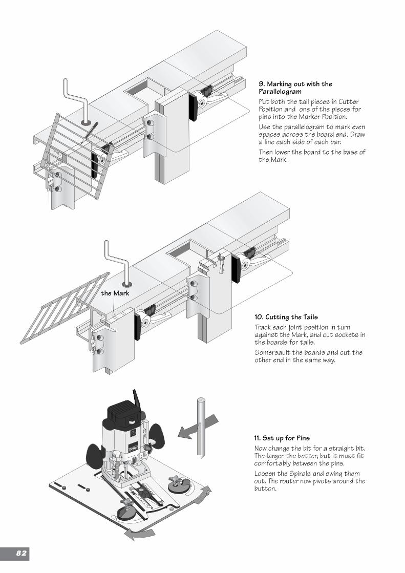
9. Marking out with theParallelogramPut both the tail pieces in CutterPosition and one of the pieces forpins into the Marker Position.Use the parallelogram to mark evenspaces across the board end. Drawa line each side of each bar.Then lower the board to the base ofthe Mark.
10. Cutting the TailsTrack each joint position in turnagainst the Mark, and cut sockets inthe boards for tails.Somersault the boards and cut theother end in the same way.
11. Set up for PinsNow change the bit for a straight bit.The larger the better, but it must fitcomfortably between the pins.Loosen the Spirals and swing themout. The router now pivots around thebutton.
the Mark
8822
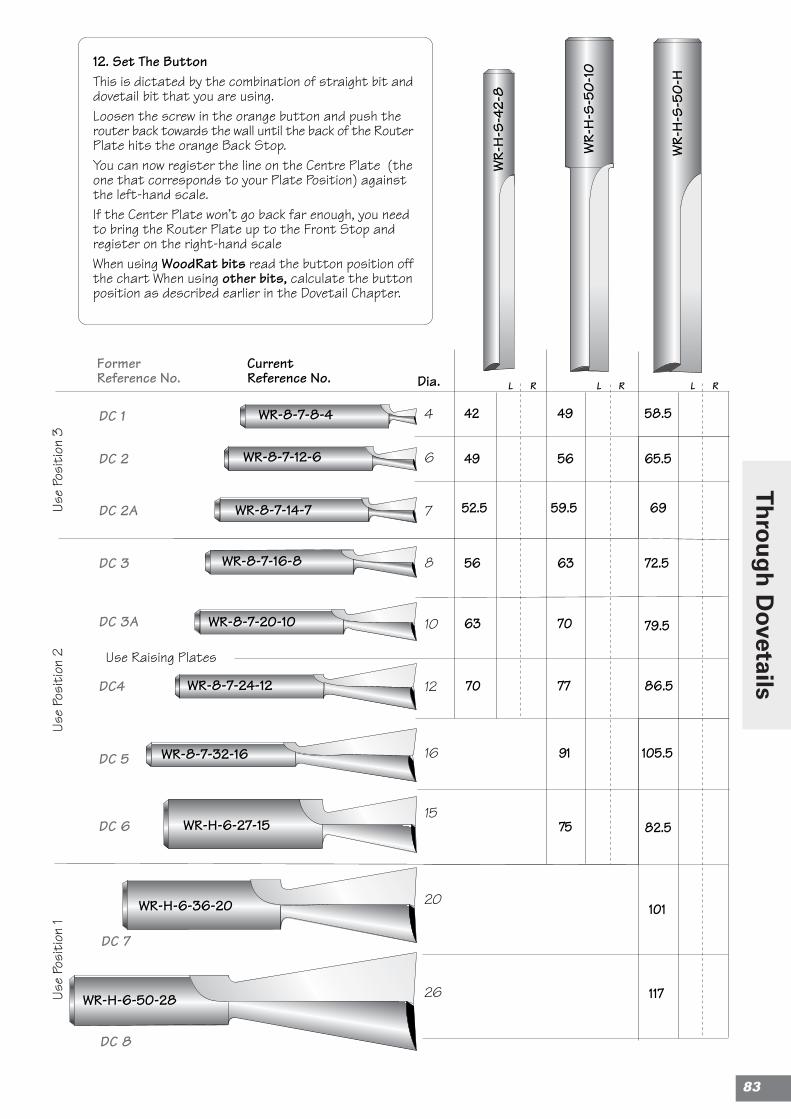
DC 2
DC4
DC 3
82.5
101
117
105.5
86.5
79.5
72.5
69
65.5
58.549
56
59.5
63
70
77
91
42
49
52.5
56
63
70
75
6
DC 2A
DC 3A
DC 5
DC 1
DC 6
4
8
10
12
16
15
20
26
FormerReference No.
7
DC 7
WR-H-6-36-20
WR-H-6-50-28
WR-H-6-27-15
WR-8-7-32-16
WR-8-7-24-12
WR-8-7-20-10
WR-8-7-14-7
WR-8-7-12-6
WR-8-7-8-4
WR-8-7-16-8
CurrentReference No.
Use
Posi
tion
1
DC 8
L R L R L R
Use
Posi
tion
2Us
e Po
siti
on 3
Use Raising Plates
Dia.
WR-
H-S
-50-
10
12. Set The ButtonThis is dictated by the combination of straight bit anddovetail bit that you are using.Loosen the screw in the orange button and push therouter back towards the wall until the back of the RouterPlate hits the orange Back Stop.You can now register the line on the Centre Plate (theone that corresponds to your Plate Position) againstthe left-hand scale.If the Center Plate won’t go back far enough, you needto bring the Router Plate up to the Front Stop andregister on the right-hand scaleWhen using WoodRat bits read the button position offthe chart When using other bits, calculate the buttonposition as described earlier in the Dovetail Chapter.
WR-
H-S
-42-
8
WR-
H-S
-50-
H
83
Th
rou
gh
Dovetails
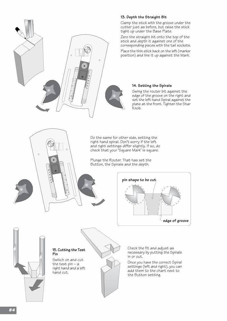
14. Setting the SpiralsSwing the router bit against theedge of the groove on the right andset the left hand Spiral against theplate at the front. Tighten the StarKnob.
Check the fit and adjust asnecessary by putting the Spiralsin or out.Once you have the correct Spiralsettings (left and right), you canadd them to the chart next tothe Button setting.
15. Cutting the TestPinSwitch on and cutthe test pin – aright hand and a lefthand cut.
Do the same for other side, setting theright hand spiral. Don’t worry if the leftand right settings differ slightly. If so, docheck that your ‘Square Mark’ is square.
Plunge the Router. That has set theButton, the Spirals and the depth.
13. Depth the Straight BitClamp the stick with the groove under thecutter just as before, but raise the sticktight up under the Base Plate.Zero the straight bit onto the top of thestick and depth it against one of thecorresponding pieces with the tail sockets.Place the thin stick back on the left (markerposition) and line it up against the Mark.
pin shape to be cut
edge of groove
8844

Cut pin #3 and then#4 which has only aleft hand cut.
Clear the waste betweenthe pins using aclockwise, circularmotion. This avoidstearout
Those pins should fitthe tails, just as thetest pin fitted the
test socket.
15. Cutting the PinsNow place the piece with the tailsin Marker Position and the pinpiece in Cutter Position.Carefully line up each socketagainst the Mark, and at eachposition�cut a pin. You should beable to see the entire Mark withinthe socket.Start on the left of the board.The first cut has only a right handcut.Track to the next position and cuta right hand cut and then a leftand so on.
the Mark
the Mark
85
Th
rou
gh
Dovetails
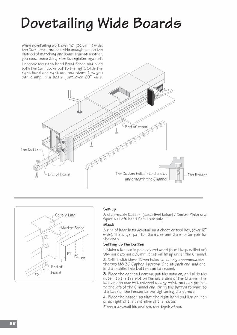
Dovetailing Wide BoardsWhen dovetailing work over 12” (300mm) wide,the Cam Locks are not wide enough to use themethod of matching one board against another,you need something else to register against.Unscrew the right-hand Fixed Fence and slideboth the Cam Locks out to the right. Slide theright hand one right out and store. Now youcan clamp in a board just over 29” wide.
Set-upA shop-made Batten, (described below) / Centre Plate andSpirals / Left-hand Cam Lock onlyStockA ring of boards to dovetail as a chest or tool-box, (over 12”wide). The longer pair for the sides and the shorter pair forthe endsSetting up the Batten1. Make a batten in pale colored wood (it will be pencilled on)914mm x 25mm x 30mm, that will fit up under the Channel.2. Drill it with three 10mm holes to loosely accommodatethe two M8 30 Caphead screws. One at each end and onein the middle. This Batten can be reused.3. Place the caphead screws, put the nuts on, and slide thenuts into the tee slot on the underside of the Channel. Thebatten can now be tightened at any point, and can projectto the left of the Channel end. Bring the batten forward tothe back of the Fences before tightening the screws.4. Place the batten so that the right hand end lies an inchor so right of the centreline of the router.Place a dovetail bit and set the depth of cut.
P1P2
Marker Fence
P1 P2 P3
Centre Line
End ofboard
The BattenThe Batten bolts into the slotunderneath the Channel
End of board
End of board
The Batten
8866
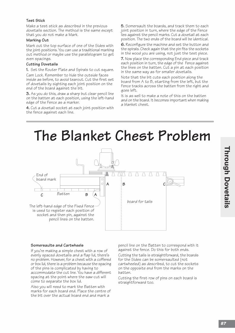
Somersaults and CartwheelsIf you’re making a simple chest with a row ofevenly spaced dovetails and a flap lid, there’sno problem. However, for a chest with a cofferedor box lid, there is a problem because the spacingof the pins is complicated by having toaccommodate the cut line. You have a differentspacing at the point where the saw-cut willcome to separate the box lid.Also you will need to mark the Batten withmarks for each board end. Place the centre ofthe bit over the actual board end and mark a
pencil line on the Batten to correspond with itagainst the fence. Do this for both ends.Cutting the tails is straightforward, the boardsfor the Sides can be somersaulted (notcartwheeled) as described, to cut the socketson the opposite end from the marks on thebatten.Cutting the first row of pins on each board isstraightforward too.
The Blanket Chest Problem
Test StickMake a test stick as described in the previousdovetails section. The method is the same exceptthat you do not make a Mark.Marking OutMark out the top surface of one of the Sides withthe joint positions. You can use a traditional markingout method or maybe use the parallelogram to geteven spacings.Cutting Dovetails1. Set the Router Plate and Spirals to cut square.Cam Lock. Remember to hide the outside facesinside as before, to avoid tearout. Cut the first setof dovetails by sighting each joint position on theend of the board against the bit.3. As you do this, draw a sharp but clear pencil lineon the batten at each position, using the left-handedge of the Fence as a marker.4. Cut a dovetail socket at each joint position withthe fence against each line.
5. Somersault the boards, and track them to eachjoint position in turn, where the edge of the Fencelies against the pencil marks. Cut a dovetail at eachposition. The two ends of the board will be identical.6. Reconfigure the machine and set the button andthe spirals. Check again that the pin fits the socketsin the wood you are using, not just the test piece.7. Now place the corresponding End piece and trackeach position in turn, the edge of the Fence againstthe lines on the batten. Cut a pin at each positionin the same way as for smaller dovetails.Note that the bit cuts each position along theboard from A to B, starting from the left, but theFence tracks across the batten from the right andgoes left.It is as well to make a note of this on the battenand on the board. It becomes important when makinga blanket chest.
Batten
The left-hand edge of the Fixed Fenceis used to register each position of
socket and then pin, against thepencil lines on the batten.
A
board for tails
CB
ABC
End ofboard mark
87
Th
rou
gh
Dovetails
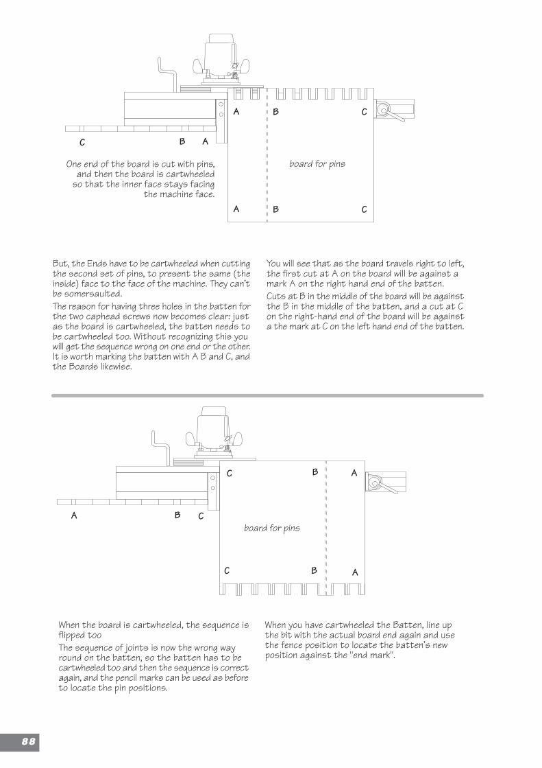
When the board is cartwheeled, the sequence isflipped tooThe sequence of joints is now the wrong wayround on the batten, so the batten has to becartwheeled too and then the sequence is correctagain, and the pencil marks can be used as beforeto locate the pin positions.
When you have cartwheeled the Batten, line upthe bit with the actual board end again and usethe fence position to locate the batten’s newposition against the "end mark".
But, the Ends have to be cartwheeled when cuttingthe second set of pins, to present the same (theinside) face to the face of the machine. They can’tbe somersaulted.The reason for having three holes in the batten forthe two caphead screws now becomes clear: justas the board is cartwheeled, the batten needs tobe cartwheeled too. Without recognizing this youwill get the sequence wrong on one end or the other.It is worth marking the batten with A B and C, andthe Boards likewise.
You will see that as the board travels right to left,the first cut at A on the board will be against amark A on the right hand end of the batten.Cuts at B in the middle of the board will be againstthe B in the middle of the batten, and a cut at Con the right-hand end of the board will be againsta the mark at C on the left hand end of the batten.
One end of the board is cut with pins,and then the board is cartwheeled
so that the inner face stays facingthe machine face.
ABC
A B C
board for pins
A CB
A CB
board for pins
AC
B AC
B
8888
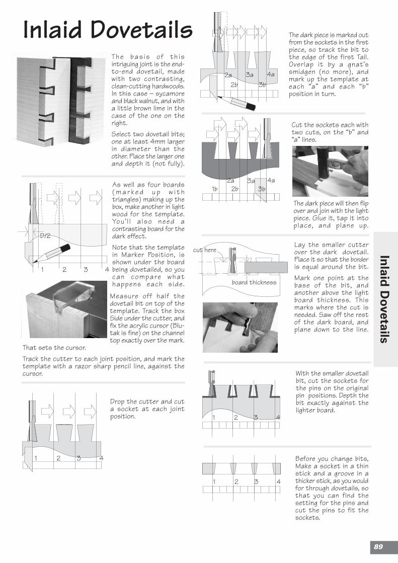
Inlaid Dovetails
D/2
1 2 3 4
The bas is o f th isintriguing joint is the end-to-end dovetail, madewith two contrasting,clean-cutting hardwoods.In this case – sycamoreand black walnut, and witha little brown lime in thecase of the one on theright.Select two dovetail bits;one at least 4mm largerin diameter than theother. Place the larger oneand depth it (not fully).
Drop the cutter and cuta socket at each jointposition.
The dark piece is marked outfrom the sockets in the firstpiece, so track the bit tothe edge of the first Tail.Overlap it by a gnat’ssmidgen (no more), andmark up the template ateach “a” and each “b”position in turn.
Cut the sockets each withtwo cuts, on the “b” and“a” lines.
The dark piece will then flipover and join with the lightpiece. Glue it, tap it intoplace, and plane up.
Lay the smaller cutterover the dark dovetail.Place it so that the borderis equal around the bit.Mark one point at thebase of the bit, andanother above the lightboard thickness. Thismarks where the cut isneeded. Saw off the restof the dark board, andplane down to the line.
With the smaller dovetailbit, cut the sockets forthe pins on the originalpin positions. Depth thebit exactly against thelighter board.
and cut the pins to fit thesockets.
Cut the sockets each withtwo cuts on the “b” and“a” lines.
1 2 3 4
1b 2b2a
3b3a 4a
cut here
board thickness
1 2 3 4
1b 2b2a
3b3a 4aAs well as four boards
( m a r k e d u p w i t htriangles) making up thebox, make another in lightwood for the template.You ’ l l a lso need acontrasting board for thedark effect.Note that the templatein Marker Position, isshown under the boardbeing dovetailed, so youcan compare whathappens each side.
Measure off half thedovetail bit on top of thetemplate. Track the boxSide under the cutter, andfix the acrylic cursor (Blu-tak is fine) on the channeltop exactly over the mark.
That sets the cursor.Track the cutter to each joint position, and mark thetemplate with a razor sharp pencil line, against thecursor.
Before you change bits,Make a socket in a thinstick and a groove in athicker stick, as you wouldfor through dovetails, sothat you can find thesetting for the pins andcut the pins to fit thesockets.
1 2 3 4
89
Inlaid
Dovetails

Notes
9900
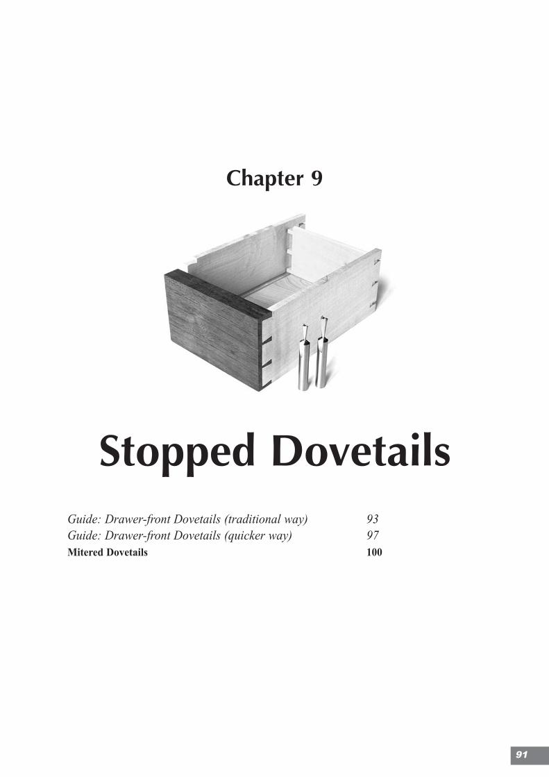
Chapter 9
Stopped DovetailsGuide: Drawer-front Dovetails (traditional way) 93Guide: Drawer-front Dovetails (quicker way) 97Mitered Dovetails 100
91
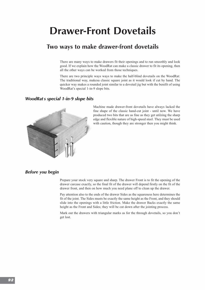
Drawer-Front DovetailsTwo ways to make drawer-front dovetails
There are many ways to make drawers fit their openings and to run smoothly and lookgood. If we explain how the WoodRat can make a classic drawer to fit its opening, thenall the other ways can be worked from those techniques.
There are two principle ways ways to make the half-blind dovetails on the WoodRat:The traditional way, makesa classic square joint as it would look if cut by hand. Thequicker way makes a rounded joint similar to a dovetail jig but with the benifit of usingWoodRat’s special 1-in-9 slope bits.
WoodRatÕs special 1-in-9 slope bits
Machine made drawer-front dovetails have always lacked thefine shape of the classic hand-cut joint - until now. We haveproduced two bits that are as fine as they get utilzing the sharpedge and flexible nature of high-speed steel. They must be usedwith caution, though they are stronger then you might think.
Before you begin
Prepare your stock very square and sharp. The drawer Front is to fit the opening of thedrawer carcase exactly, so the final fit of the drawer will depend firstly on the fit of thedrawer front, and then on how much you need plane off to clean up the drawer.
Pay attention also to the ends of the drawer Sides as the squareness here determines thefit of the joint. The Sides musts be exactly the same height as the Front, and they shouldslide into the openings with a little friction. Make the drawer Backs exactly the sameheight as the Front and Sides; they will be cut down after the jointing process.
Mark out the drawers with triangular marks as for the through dovetails, so you don’tget lost.
9922
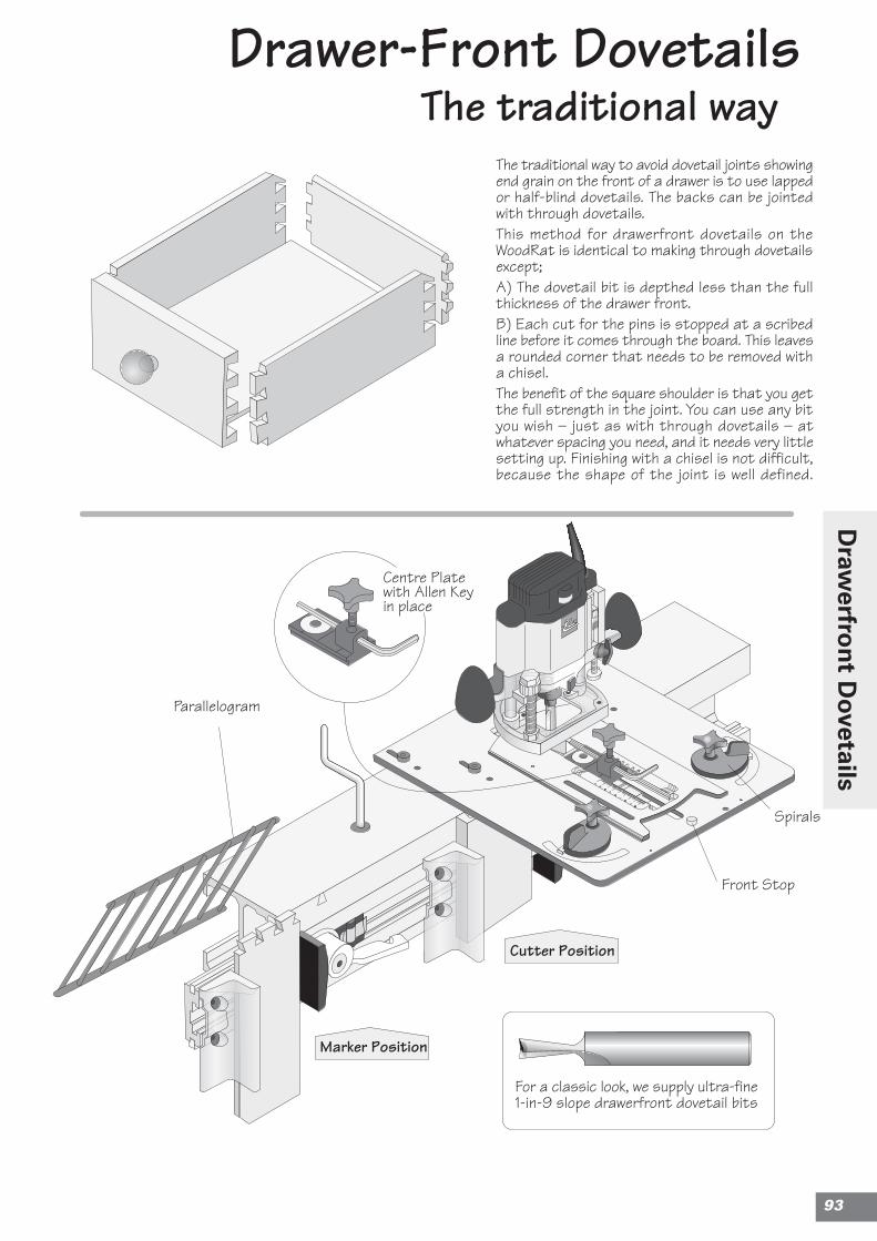
Cutter Position
Marker Position
Drawer-Front DovetailsThe traditional way
The traditional way to avoid dovetail joints showingend grain on the front of a drawer is to use lappedor half-blind dovetails. The backs can be jointedwith through dovetails.This method for drawerfront dovetails on theWoodRat is identical to making through dovetailsexcept;A) The dovetail bit is depthed less than the fullthickness of the drawer front.B) Each cut for the pins is stopped at a scribedline before it comes through the board. This leavesa rounded corner that needs to be removed witha chisel.The benefit of the square shoulder is that you getthe full strength in the joint. You can use any bityou wish – just as with through dovetails – atwhatever spacing you need, and it needs very littlesetting up. Finishing with a chisel is not difficult,because the shape of the joint is well defined.
Spirals
Front Stop
Parallelogram
Centre Platewith Allen Keyin place
For a classic look, we supply ultra-fine1-in-9 slope drawerfront dovetail bits
93
Draw
erfron
t Dovetails
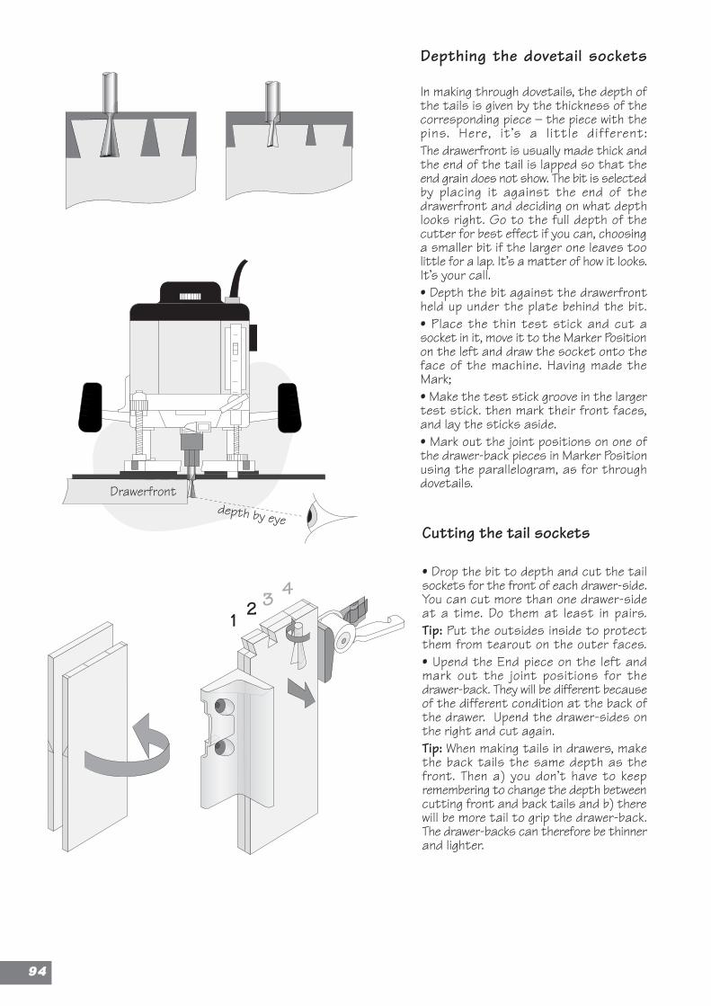
1 2 3 4
Drawerfrontdepth by eye
Cutting the tail sockets
• Drop the bit to depth and cut the tailsockets for the front of each drawer-side.You can cut more than one drawer-sideat a time. Do them at least in pairs.Tip: Put the outsides inside to protectthem from tearout on the outer faces.• Upend the End piece on the left andmark out the joint positions for thedrawer-back. They will be different becauseof the different condition at the back ofthe drawer. Upend the drawer-sides onthe right and cut again.Tip: When making tails in drawers, makethe back tails the same depth as thefront. Then a) you don’t have to keepremembering to change the depth betweencutting front and back tails and b) therewill be more tail to grip the drawer-back.The drawer-backs can therefore be thinnerand lighter.
Depthing the dovetail sockets
In making through dovetails, the depth ofthe tails is given by the thickness of thecorresponding piece – the piece with thepins. Here, it’s a l ittle different:The drawerfront is usually made thick andthe end of the tail is lapped so that theend grain does not show. The bit is selectedby placing it against the end of thedrawerfront and deciding on what depthlooks right. Go to the full depth of thecutter for best effect if you can, choosinga smaller bit if the larger one leaves toolittle for a lap. It’s a matter of how it looks.It’s your call.• Depth the bit against the drawerfrontheld up under the plate behind the bit.• Place the thin test stick and cut asocket in it, move it to the Marker Positionon the left and draw the socket onto theface of the machine. Having made theMark;• Make the test stick groove in the largertest stick. then mark their front faces,and lay the sticks aside.• Mark out the joint positions on one ofthe drawer-back pieces in Marker Positionusing the parallelogram, as for throughdovetails.
9944
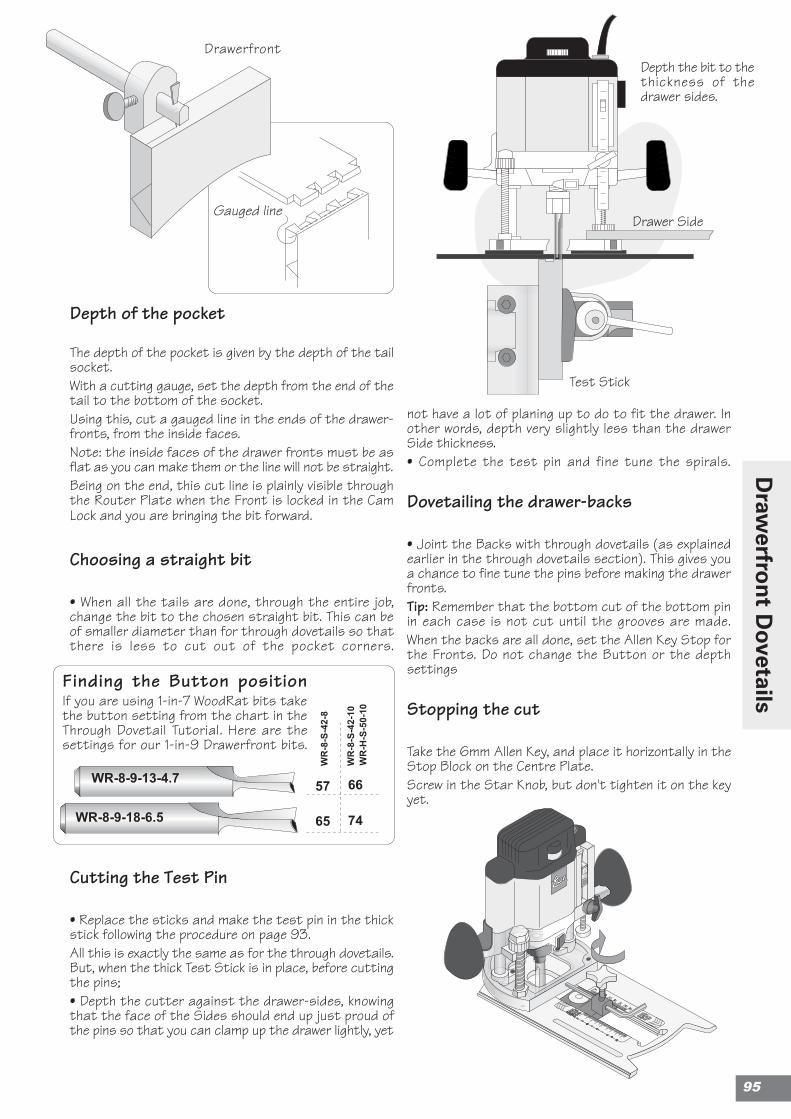
Depth the bit to thethickness of thedrawer sides.
Gauged line
Depth of the pocket
The depth of the pocket is given by the depth of the tailsocket.With a cutting gauge, set the depth from the end of thetail to the bottom of the socket.Using this, cut a gauged line in the ends of the drawer-fronts, from the inside faces.Note: the inside faces of the drawer fronts must be asflat as you can make them or the line will not be straight.Being on the end, this cut line is plainly visible throughthe Router Plate when the Front is locked in the CamLock and you are bringing the bit forward.
Choosing a straight bit
• When all the tails are done, through the entire job,change the bit to the chosen straight bit. This can beof smaller diameter than for through dovetails so thatthere is less to cut out of the pocket corners.
Cutting the Test Pin
• Replace the sticks and make the test pin in the thickstick following the procedure on page 93.All this is exactly the same as for the through dovetails.But, when the thick Test Stick is in place, before cuttingthe pins;• Depth the cutter against the drawer-sides, knowingthat the face of the Sides should end up just proud ofthe pins so that you can clamp up the drawer lightly, yet
not have a lot of planing up to do to fit the drawer. Inother words, depth very slightly less than the drawerSide thickness.• Complete the test pin and fine tune the spirals.
Dovetailing the drawer-backs
• Joint the Backs with through dovetails (as explainedearlier in the through dovetails section). This gives youa chance to fine tune the pins before making the drawerfronts.Tip: Remember that the bottom cut of the bottom pinin each case is not cut until the grooves are made.When the backs are all done, set the Allen Key Stop forthe Fronts. Do not change the Button or the depthsettings
Stopping the cut
Take the 6mm Allen Key, and place it horizontally in theStop Block on the Centre Plate.Screw in the Star Knob, but don't tighten it on the keyyet.
Test Stick
Drawer Side
Drawerfront
WR-8
-S-4
2-8
WR-8
-S-4
2-10
57 66
65 74
WR-H
-S-5
0-10
WR-8-9-13-4.7
WR-8-9-18-6.5
Finding the Button positionIf you are using 1-in-7 WoodRat bits takethe button setting from the chart in theThrough Dovetail Tutorial. Here are thesettings for our 1-in-9 Drawerfront bits.
95
Draw
erfron
t Dovetails
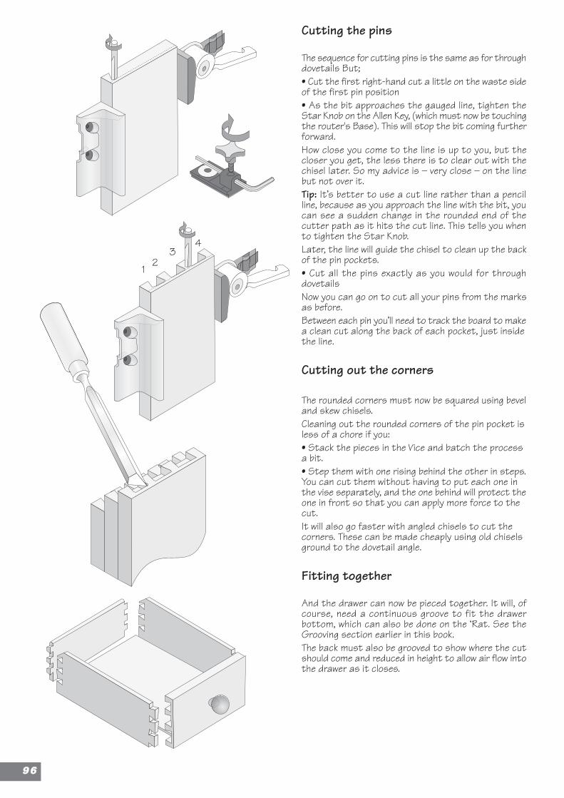
12
34
Cutting the pins
The sequence for cutting pins is the same as for throughdovetails But;• Cut the first right-hand cut a little on the waste sideof the first pin position• As the bit approaches the gauged line, tighten theStar Knob on the Allen Key, (which must now be touchingthe router's Base). This will stop the bit coming furtherforward.How close you come to the line is up to you, but thecloser you get, the less there is to clear out with thechisel later. So my advice is – very close – on the linebut not over it.Tip: It’s better to use a cut line rather than a pencilline, because as you approach the line with the bit, youcan see a sudden change in the rounded end of thecutter path as it hits the cut line. This tells you whento tighten the Star Knob.Later, the line will guide the chisel to clean up the backof the pin pockets.• Cut all the pins exactly as you would for throughdovetailsNow you can go on to cut all your pins from the marksas before.Between each pin you’ll need to track the board to makea clean cut along the back of each pocket, just insidethe line.
Cutting out the corners
The rounded corners must now be squared using beveland skew chisels.Cleaning out the rounded corners of the pin pocket isless of a chore if you:• Stack the pieces in the Vice and batch the processa bit.• Step them with one rising behind the other in steps.You can cut them without having to put each one inthe vise separately, and the one behind will protect theone in front so that you can apply more force to thecut.It will also go faster with angled chisels to cut thecorners. These can be made cheaply using old chiselsground to the dovetail angle.
Fitting together
And the drawer can now be pieced together. It will, ofcourse, need a continuous groove to fit the drawerbottom, which can also be done on the ‘Rat. See theGrooving section earlier in this book.The back must also be grooved to show where the cutshould come and reduced in height to allow air flow intothe drawer as it closes.
9966
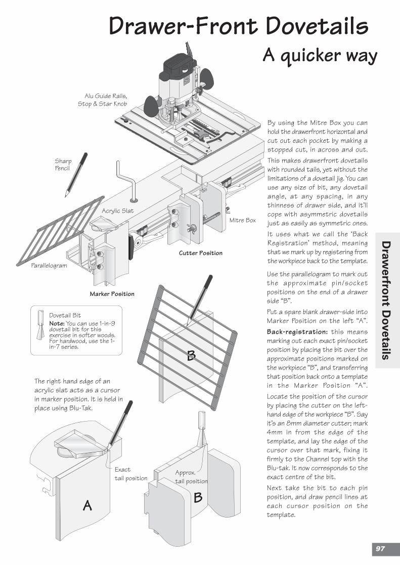
Cutter Position
Drawer-Front DovetailsA quicker way
Marker Position
By using the Mitre Box you canhold the drawerfront horizontal andcut out each pocket by making astopped cut, in across and out.This makes drawerfront dovetailswith rounded tails, yet without thelimitations of a dovetail jig. You canuse any size of bit, any dovetailangle, at any spacing, in anythinness of drawer side, and it’llcope with asymmetric dovetailsjust as easily as symmetric ones.It uses what we call the ‘BackRegistration’ method, meaningthat we mark up by registering fromthe workpiece back to the template.
Use the parallelogram to mark outthe approximate pin/socketpositions on the end of a drawerside “B”.Put a spare blank drawer-side intoMarker Position on the left “A”.Back-registration: this meansmarking out each exact pin/socketposition by placing the bit over theapproximate positions marked onthe workpiece “B”, and transferringthat position back onto a templatein the Marker Position “A”.Locate the position of the cursorby placing the cutter on the left-hand edge of the workpiece “B”. Sayit’s an 8mm diameter cutter; mark4mm in from the edge of thetemplate, and lay the edge of thecursor over that mark, fixing itfirmly to the Channel top with theBlu-tak. It now corresponds to theexact centre of the bit.Next take the bit to each pinposition, and draw pencil lines ateach cursor position on thetemplate.
The right hand edge of anacrylic slat acts as a cursorin marker position. It is held inplace using Blu-Tak.
Parallelogram
Alu Guide Rails,Stop & Star Knob
Mitre Box
SharpPencil
B
A B
Approx.tail position
Acrylic Slat
Exacttail position
Dovetail BitNote: You can use 1-in-9dovetail bit for thisexercise in softer woods.For hardwood, use the 1-in-7 series.
97
Draw
erfron
t Dovetails
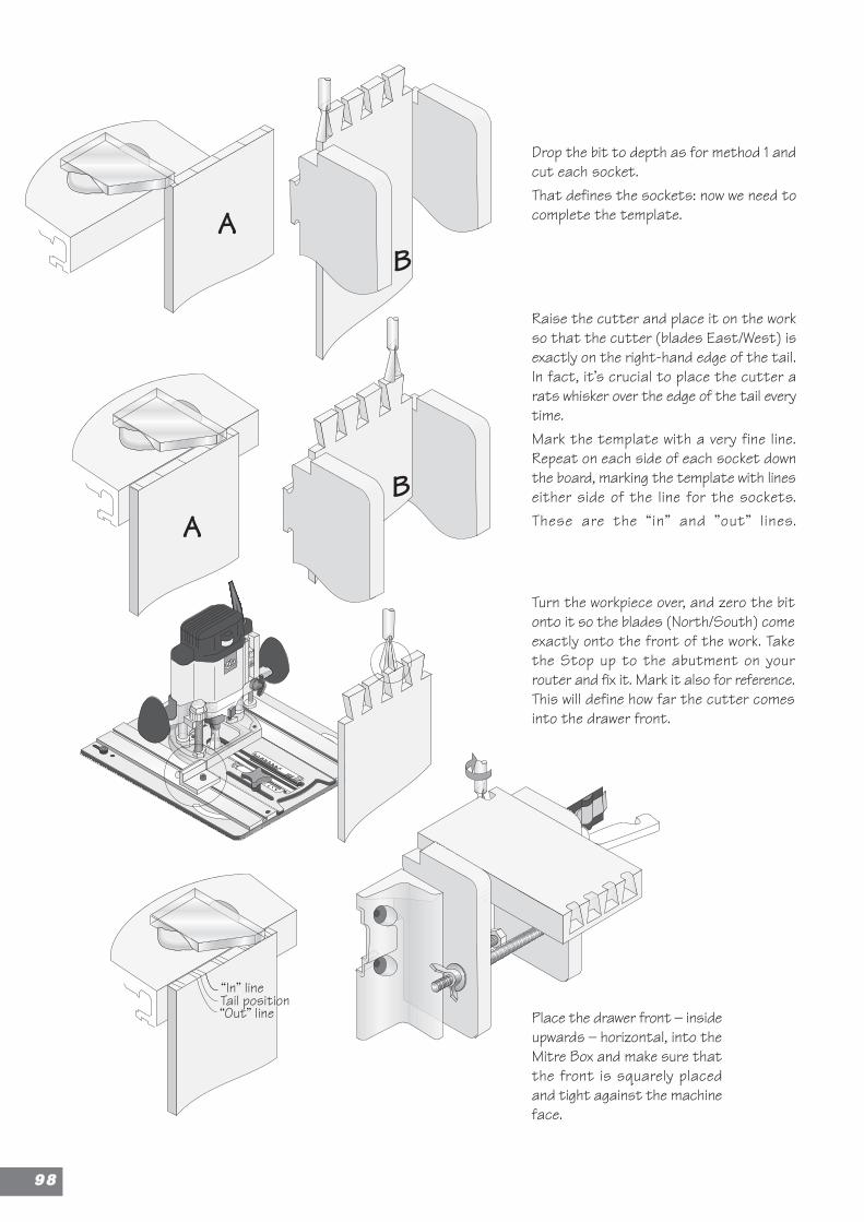
Drop the bit to depth as for method 1 andcut each socket.That defines the sockets: now we need tocomplete the template.
Raise the cutter and place it on the workso that the cutter (blades East/West) isexactly on the right-hand edge of the tail.In fact, it’s crucial to place the cutter arats whisker over the edge of the tail everytime.Mark the template with a very fine line.Repeat on each side of each socket downthe board, marking the template with lineseither side of the line for the sockets.These are the “in” and ”out” lines.
A
A
B
B
Turn the workpiece over, and zero the bitonto it so the blades (North/South) comeexactly onto the front of the work. Takethe Stop up to the abutment on yourrouter and fix it. Mark it also for reference.This will define how far the cutter comesinto the drawer front.
Place the drawer front – insideupwards – horizontal, into theMitre Box and make sure thatthe front is squarely placedand tight against the machineface.
“In” line
“Out” lineTail position
9988
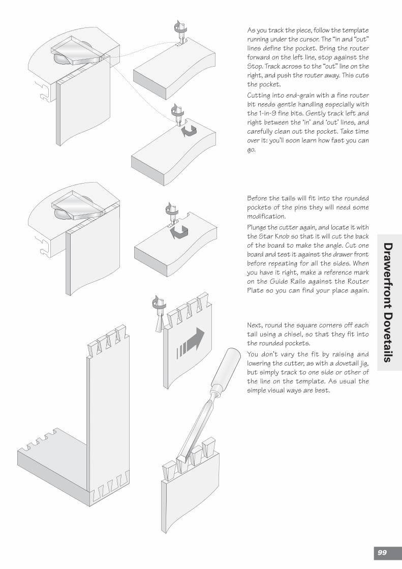
As you track the piece, follow the templaterunning under the cursor. The “in and “out”lines define the pocket. Bring the routerforward on the left line, stop against theStop. Track across to the “out” line on theright, and push the router away. This cutsthe pocket.Cutting into end-grain with a fine routerbit needs gentle handling especially withthe 1-in-9 fine bits. Gently track left andright between the ‘in’ and ‘out’ lines, andcarefully clean out the pocket. Take timeover it: you’ll soon learn how fast you cango.
Next, round the square corners off eachtail using a chisel, so that they fit intothe rounded pockets.You don’t vary the fit by raising andlowering the cutter, as with a dovetail jig,but simply track to one side or other ofthe line on the template. As usual thesimple visual ways are best.
Before the tails will fit into the roundedpockets of the pins they will need somemodification.Plunge the cutter again, and locate it withthe Star Knob so that it will cut the backof the board to make the angle. Cut oneboard and test it against the drawer frontbefore repeating for all the sides. Whenyou have it right, make a reference markon the Guide Rails against the RouterPlate so you can find your place again.
99
Draw
erfron
t Dovetails
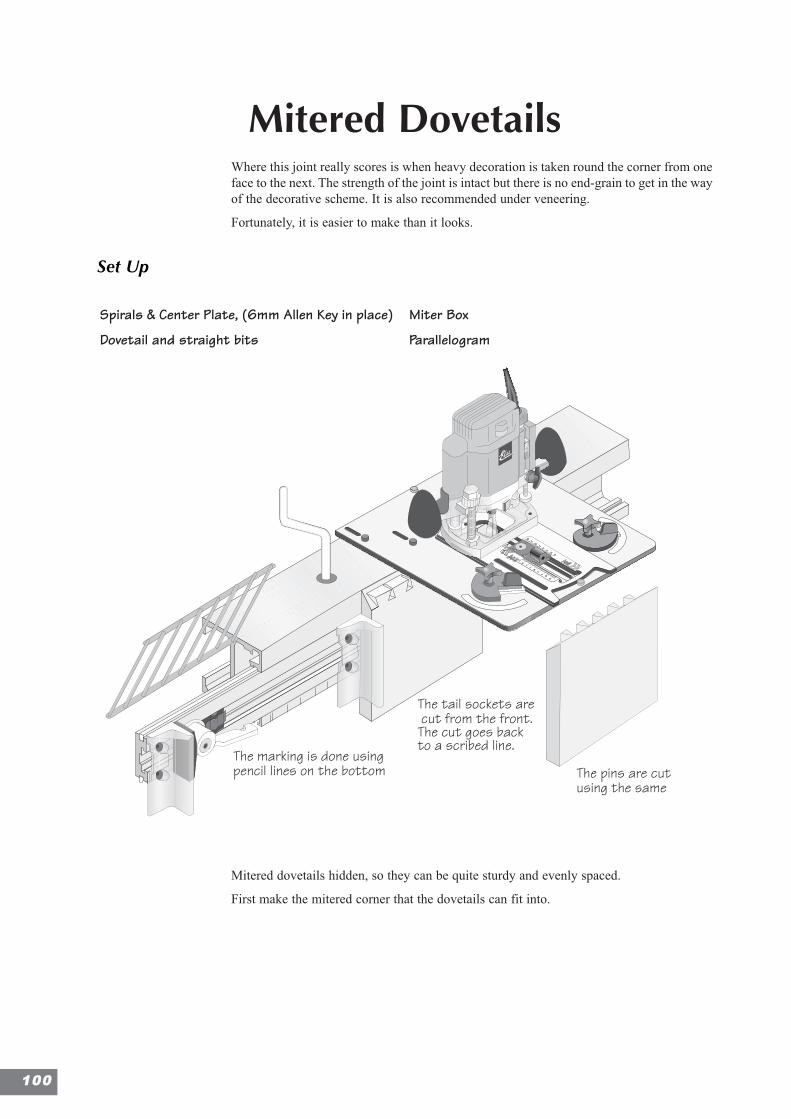
Mitered DovetailsWhere this joint really scores is when heavy decoration is taken round the corner from oneface to the next. The strength of the joint is intact but there is no end-grain to get in the wayof the decorative scheme. It is also recommended under veneering.
Fortunately, it is easier to make than it looks.
Set Up
Mitered dovetails hidden, so they can be quite sturdy and evenly spaced.
First make the mitered corner that the dovetails can fit into.
The Outside socket is cut inonly as a half circle to definethe size of the socket. It islater cut away at 45°
For the outer tails, the sockets arecut as just a half circle, giving thesize, position and shape of the pin
This piece is thentaken out with thechisel
The marking is done usingpencil lines on the bottom The pins are cut
using the same
The tail sockets are cut from the front.The cut goes backto a scribed line.
Spirals & Center Plate, (6mm Allen Key in place)
Dovetail and straight bits
Miter Box
Parallelogram
110000
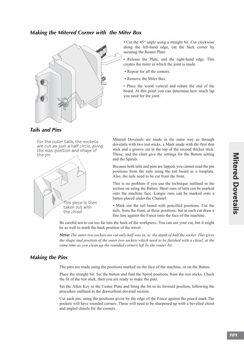
Making the Mitered Corner with the Miter Box
• Cut the 45° angle using a straight bit. Cut clockwisealong the left-hand edge, cut the back corner bysecuring the Router Plate.
• Release the Plate, and the right-hand edge. Thiscreates the miter in which the joint is made.
• Repeat for all the corners.
• Remove the Miter Box.
• Place the wood vertical and rebate the end of theboard. At this point you can determine how much lapyou need for the joint.
Tails and Pins
Mitered Dovetails are made in the same way as throughdovetails with two test sticks, a Mark made with the first thinstick and a groove cut in the top of the second thicker stick.These, and the chart give the settings for the Button settingand the Spirals.
Because both tails and pins are lapped, you cannot read the pinpositions from the tails using the tail board as a template.Also, the tails need to be cut from the front.
This is no problem if you use the technique outlined in thesection on using the Batten. Short runs of tails can be markedonto the machine face. Longer runs can be marked onto abatten placed under the Channel.
• Mark out the tail board with pencilled positions. Cut thetails, from the front, at these positions, but at each cut draw afine line against the Fence onto the face of the machine.
Be careful not to cut too far into the back of the workpiece. You can see your cut, but it mightbe as well to mark the back position of the travel.
Note: The outer two sockets are cut only half way in; ie. the depth of half the socket. This givesthe shape and position of the outer two sockets which need to be finished with a chisel, at thesame time as you clean up the rounded corners left by the router bit.
Making the Pins
The pins are made using the positions marked on the face of the machine, or on the Batten.
Place the straight bit. Set the button and find the Spiral positions from the test sticks. Checkthe fit of the test stick, then you are ready to make the pins.
Set the Allen Key in the Center Plate and bring the bit to its forward position, following theprocedure outlined in the drawerfront dovetail section.
Cut each pin, using the positions given by the edge of the Fence against the pencil mark.Thepockets will have rounded corners. These will need to be sharpened up with a bevelled chiseland angled chisels for the corners.
The Outside socket is cutin only as a half circle todefine the size of thesocket. It is later cut awayat 45°
For the outer tails, the socketsare cut as just a half circle, givingthe size, position and shape ofthe pin
This piece is thentaken out withthe chisel
The Outside socket is cutin only as a half circle todefine the size of thesocket. It is later cut awayat 45°
For the outer tails, the socketsare cut as just a half circle, givingthe size, position and shape ofthe pin
This piece is thentaken out withthe chisel
101
Mitered
Dovetails

Notes
110022
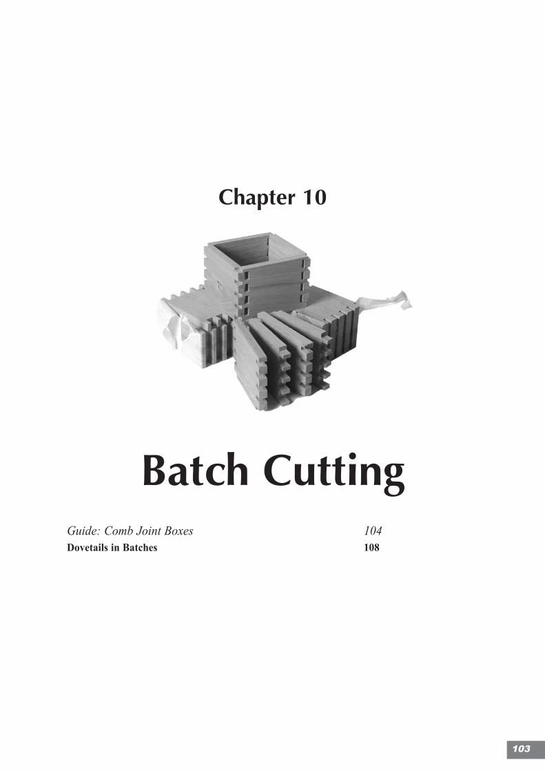
Chapter 10
Batch CuttingGuide: Comb Joint Boxes 104Dovetails in Batches 108
103
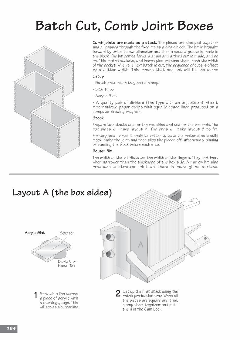
2
Layout A (the box sides)
1
Batch Cut, Comb Joint BoxesComb joints are made as a stack. The pieces are clamped togetherand all passed through the fixed bit as a single block. The bit is broughtforward by twice its own diameter and then a second groove is made inthe block. The bit comes forward again and a third cut is made, and soon. This makes sockets, and leaves pins between them, each the widthof the socket. When the next batch is cut, the sequence of cuts is offsetby a cutter width. This means that one set will fit the other.Setup- Batch production tray and a clamp.- Star Knob- Acrylic Slat- A quality pair of dividers (the type with an adjustment wheel).Alternatively, paper strips with equally space lines produced on acomputer drawing program.StockPrepare two stacks one for the box sides and one for the box ends. Thebox sides will have layout A. The ends will take layout B to fit.For very small boxes it could be better to leave the material as a solidblock, make the joint and then slice the pieces off afterwards, planingor sanding the block before each slice.Router BitThe width of the bit dictates the width of the fingers. They look bestwhen narrower than the thickness of the box side. A narrow bit alsoproduces a stronger joint as there is more glued surface.
Scratch a line acrossa piece of acrylic witha marking guage. Thiswill act as a cursor line.
Set up the first stack using thebatch production tray. When allthe pieces are square and true,clamp them together and putthem in the Cam Lock.
AAcrylic Slat Scratch
Blu-TaK orHandi Tak
110044
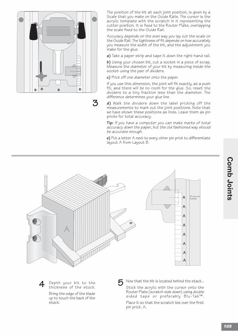
Depth your bit to thethickness of the stock.Bring the edge of the bladeup to touch the back of thestack.
The position of the bit at each joint position, is given by aScale that you make on the Guide Rails. The cursor is theacrylic template with the scratch in it representing thecutter position. It is fixed to the Router Plate, overlappingthe scale fixed to the Guide Rail.Accuracy depends on the even way you lay out the scale onthe Guide Rail. The tightness of fit depends on how accuratelyyou measure the width of the bit, and the adjustment youmake for the glue.a) Take a paper strip and tape it down the right-hand rail.b) Using your chosen bit, cut a socket in a piece of scrap.Measure the diameter of your bit by measuring inside thesocket using the pair of dividers.c) Prick off one diameter onto the paper.If you use this dimension, the joint will fit exactly, as a pushfit, and there will be no room for the glue. So, reset thedividers to a tiny fraction less than the diameter. Thedifference determines your glue line.d) Walk the dividers down the label pricking off themeasurements to mark out the joint positions. Note thatwe have shown these positions as lines. Leave them as pinpricks for total accuracy.Tip: If you have a computer you can make marks of totalaccuracy down the paper, but the old fashioned way shouldbe accurate enough.e) Put a letter A next to every other pin prick to differentiatelayout A from Layout B.
Now that the bit is located behind the stack...Stick the acrylic with the cursor onto theRouter Plate (scratch side down) using doublesided tape or preferably Blu-Tak™.Place it so that the scratch lies over the firstpin prick. A.
3
4 5
A
A
A
A
A
A
A
A
B’s are notmarked
A
105
Co
mb
Join
ts
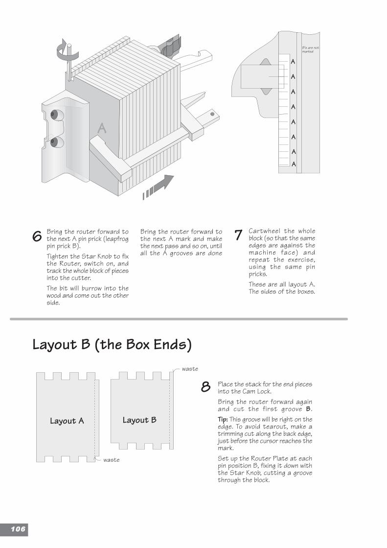
Bring the router forward tothe next A pin prick (leapfrogpin prick B).Tighten the Star Knob to fixthe Router, switch on, andtrack the whole block of piecesinto the cutter.The bit will burrow into thewood and come out the otherside.
Bring the router forward tothe next A mark and makethe next pass and so on, untilall the A grooves are done
Layout B (the Box Ends)
Cartwheel the wholeblock (so that the sameedges are against themachine face) andrepeat the exercise,using the same pinpricks.These are all layout A.The sides of the boxes.
8
76
Place the stack for the end piecesinto the Cam Lock.Bring the router forward againand cut the first groove B.Tip: This groove will be right on theedge. To avoid tearout, make atrimming cut along the back edge,just before the cursor reaches themark.Set up the Router Plate at eachpin position B, fixing it down withthe Star Knob, cutting a groovethrough the block.
A
Layout A Layout B
waste
A
A
A
A
A
A
A
A
B’s are notmarked
waste
110066
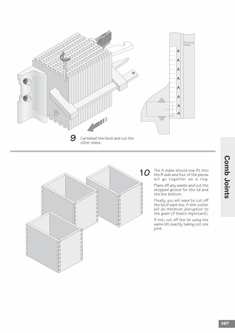
The A sides should now fit intothe B side and four of the pieceswill go together as a ring.Plane off any waste and cut thestopped groove for the lid andthe box bottom.Finally, you will need to cut offthe lid of each box. A thin cutterwill do minimum disruption tothe grain (if that’s important).If not, cut off the lid using thesame bit exactly taking out onejoint
Cartwheel the block and cut theother sides.
9
10
BA
A
A
A
A
A
A
A
B’s are notmarked
107
Co
mb
Join
ts
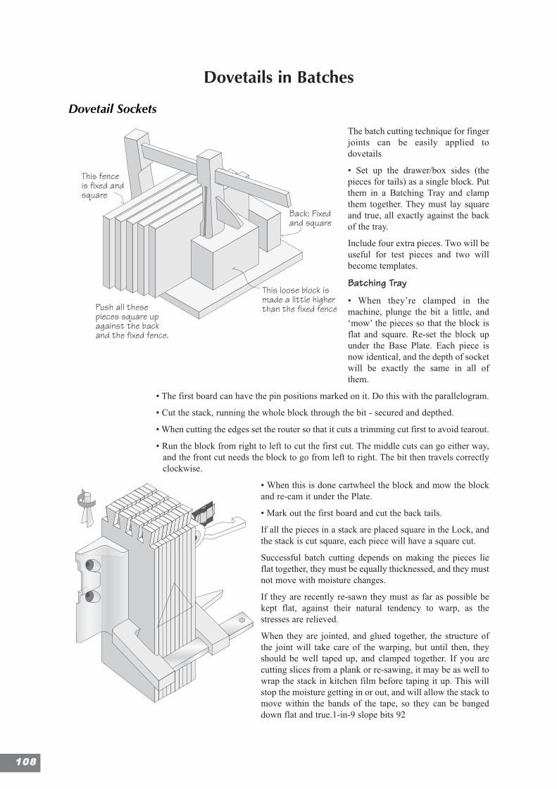
Dovetails in Batches
Dovetail Sockets
The batch cutting technique for fingerjoints can be easily applied todovetails
• Set up the drawer/box sides (thepieces for tails) as a single block. Putthem in a Batching Tray and clampthem together. They must lay squareand true, all exactly against the backof the tray.
Include four extra pieces. Two will beuseful for test pieces and two willbecome templates.
Batching Tray
• When they’re clamped in themachine, plunge the bit a little, and‘mow’ the pieces so that the block isflat and square. Re-set the block upunder the Base Plate. Each piece isnow identical, and the depth of socketwill be exactly the same in all ofthem.
• The first board can have the pin positions marked on it. Do this with the parallelogram.
• Cut the stack, running the whole block through the bit - secured and depthed.
• When cutting the edges set the router so that it cuts a trimming cut first to avoid tearout.
• Run the block from right to left to cut the first cut. The middle cuts can go either way,and the front cut needs the block to go from left to right. The bit then travels correctlyclockwise.
• When this is done cartwheel the block and mow the blockand re-cam it under the Plate.
• Mark out the first board and cut the back tails.
If all the pieces in a stack are placed square in the Lock, andthe stack is cut square, each piece will have a square cut.
Successful batch cutting depends on making the pieces lieflat together, they must be equally thicknessed, and they mustnot move with moisture changes.
If they are recently re-sawn they must as far as possible bekept flat, against their natural tendency to warp, as thestresses are relieved.
When they are jointed, and glued together, the structure ofthe joint will take care of the warping, but until then, theyshould be well taped up, and clamped together. If you arecutting slices from a plank or re-sawing, it may be as well towrap the stack in kitchen film before taping it up. This willstop the moisture getting in or out, and will allow the stack tomove within the bands of the tape, so they can be bangeddown flat and true.1-in-9 slope bits 92
This fenceis fixed andsquare
Back: Fixedand square
Push all thesepieces square upagainst the backand the fixed fence.
This loose block ismade a little higherthan the fixed fence
110088
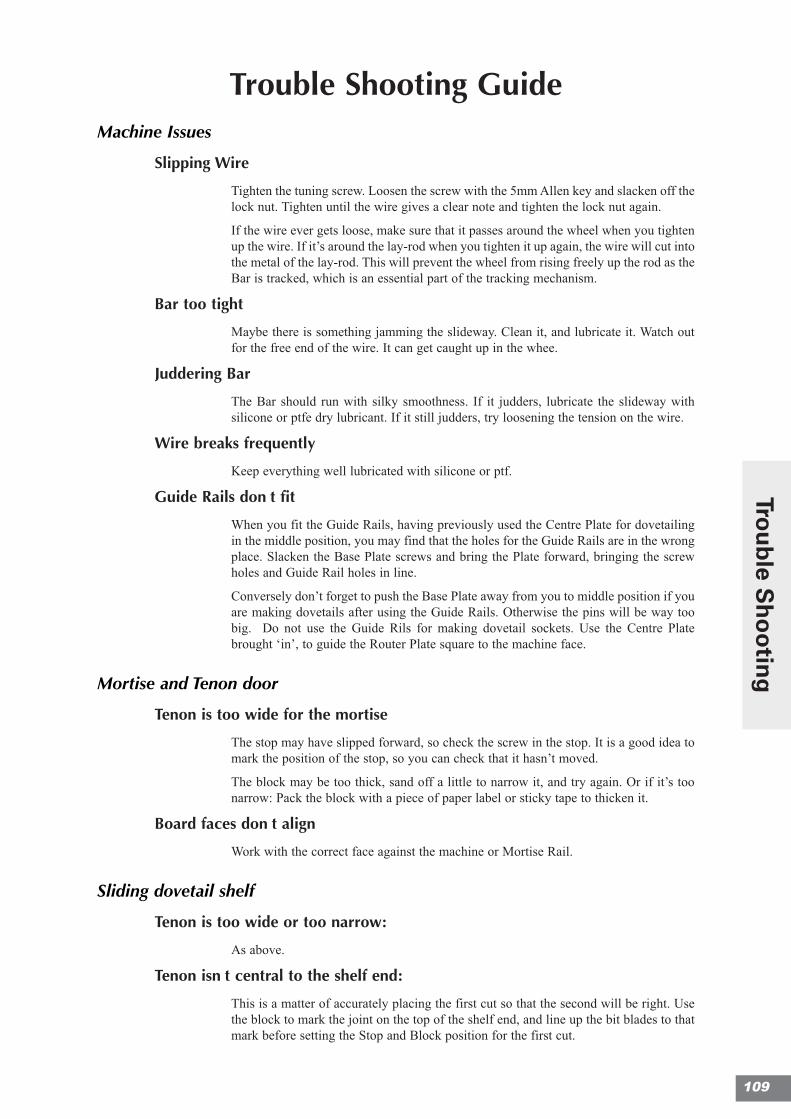
Trouble Shooting GuideMachine Issues
Slipping Wire
Tighten the tuning screw. Loosen the screw with the 5mm Allen key and slacken off thelock nut. Tighten until the wire gives a clear note and tighten the lock nut again.
If the wire ever gets loose, make sure that it passes around the wheel when you tightenup the wire. If it’s around the lay-rod when you tighten it up again, the wire will cut intothe metal of the lay-rod. This will prevent the wheel from rising freely up the rod as theBar is tracked, which is an essential part of the tracking mechanism.
Bar too tight
Maybe there is something jamming the slideway. Clean it, and lubricate it. Watch outfor the free end of the wire. It can get caught up in the whee.
Juddering Bar
The Bar should run with silky smoothness. If it judders, lubricate the slideway withsilicone or ptfe dry lubricant. If it still judders, try loosening the tension on the wire.
Wire breaks frequently
Keep everything well lubricated with silicone or ptf.
Guide Rails donÕt fit
When you fit the Guide Rails, having previously used the Centre Plate for dovetailingin the middle position, you may find that the holes for the Guide Rails are in the wrongplace. Slacken the Base Plate screws and bring the Plate forward, bringing the screwholes and Guide Rail holes in line.
Conversely don’t forget to push the Base Plate away from you to middle position if youare making dovetails after using the Guide Rails. Otherwise the pins will be way toobig. Do not use the Guide Rils for making dovetail sockets. Use the Centre Platebrought ‘in’, to guide the Router Plate square to the machine face.
Mortise and Tenon door
Tenon is too wide for the mortise
The stop may have slipped forward, so check the screw in the stop. It is a good idea tomark the position of the stop, so you can check that it hasn’t moved.
The block may be too thick, sand off a little to narrow it, and try again. Or if it’s toonarrow: Pack the block with a piece of paper label or sticky tape to thicken it.
Board faces donÕt align
Work with the correct face against the machine or Mortise Rail.
Sliding dovetail shelf
Tenon is too wide or too narrow:
As above.
Tenon isnÕt central to the shelf end:
This is a matter of accurately placing the first cut so that the second will be right. Usethe block to mark the joint on the top of the shelf end, and line up the bit blades to thatmark before setting the Stop and Block position for the first cut.
109
Trou
ble S
ho
otin
g

Through Dovetails
Pin size is too big or too small:
Check that the router plate goes right back to the backstop to get a correct reading forthe Button setting.
Has the Button worked loose? Make sure it is tight and that the router has not hit thestop block on the centreplate, and pushed it forwards. Push the router back to the BackStop and check the reading.
Lapped Dovetails (traditional way)
Joint is too tightAs for through dovetails. If you have not measured the depth of the tail socketaccurately, and make the pocket too shallow, the tails will be tight, and there will be agap at the inside of the drawer.
Joint is too loose
As for through dovetails If you make the pocket too deep the tails will fit, but you willhave an unsightly gap at the front end of the tails.
Boards mis-matched or joggled
Aligning the side to the drawer front is crucial for drawers that are to fit the openingsexactly. Using the two test stick method should give perfect alignment. If front and sideare slightly out of line, you can tweak the spirals:
Look at the left hand pin. If it needs to be bigger, to bring the left hand edge of the draw-er front into line, move the left hand spiral out, and compensate by bringing the righthand Spiral ‘in’ the same amount.
Lapped Dovetails (quick way)
Joints are too tight or too loose:
The fit here is given by eye, lining the cursor up against the pencil line. If the bit isaccurately lined up with the edges of the sockets, and the pencil lines are drawn finely.
Batch Cut Comb Joints
If the scale is accurate the joints may all be too tight or too loose together, but they willall align. If the interval between the joints is not exactly regular, the scale will need tobe remade with greater accuracy
Joints are too tight
The joint spacing is too wide. Measure the joint again and tighten up the spacing of themarks on the scale
Joints are too loose
The spacing of the joint positions is too tight. Remake the scale and give the joints afraction wider spacing.
111100

IndexA
Acrylic Slats 14
Allen Key 9, 40, 100, 101
Alu Guide Rails 9
Angle Jig 48
Angled Mortise and Tenon 48
B
Base Plate 9, 16, 20, 21, 22, 25
Batch Cutting 3, 13, 103, 108
Batten 9, 101
Biscuit Joints 29
Blu-Tac 14
Box Lids 2, 23, 34
Brush 9, 25, 26, 27, 29, 33, 34,37, 39, 55
Button position 78
C
Cable 9
Carcass Mitered Dowel Joint 63
Cartwheeling 21
Center Liner 9, 37
Center Plate 9, 16, 40, 75, 76,77, 78, 79, 100, 101
Chair Making 2, 41, 48, 49, 53
Channel 9, 43, 75, 101
Clamps 13, 37, 53
Comb Joint Boxes 3, 103
Compound Angle Jig 48
Cone Shaped Bit 31
Contacting Us 5
Cope and Stick Joint 13, †30
Corner Halving Joints 39
Cross Halving Joints 39
Cutter Block 9, 16, 25, 26, 33
D
Decorative Profiles 2, 23, 27
Degrees and slope numbers 74
Depth of Cut 22, 25, 43, 49, 72,79
Depthing 2, 15, 20, 22, 32, 55,72, 79
DeWalt 625 43
Dials 75
Dovetail Angles 73
Dovetail Bits 77
Dovetails in Batches 103
Dowel Carcassing Joint 63
Dowel framing Joint 63
Dowel Joints 3, 13, 51, 53, 54,63
Dowels 3, 51, 62, 63
Down-Cut 19, 20, 27, †30, 31,43
Drawer-front Dovetails 3, 13,40, 91, 92
Dust Chute 9
DVD 13
E
East/West 21, 65, 75
East/West Registration 65
Egg Crate Construction 39
F
Finger Joints 3, 5, 13, 65, 67, 69,75, 79, 108
Forked Tenon 49
Forum 5
G
Gauging Pieces 22
Guide Rail 32
H
Halving Joints 2, 35, 39, 40, 41,50
Hand Feeding 25, 43
Handi-Tak 14
High-Speed Steel 17, 92
HSS Bits 2, 15
HSS vs. TCT Dovetail Bits 74
I
Identifying the Boards 78
Inlaid Dovetails 3, 71, 89
Introduction 2, 4, 65
J
Jacobs Power Collet 14
Joggle 21, 72
K
Knuckle Joints 3, 65
L
Language 5
Lap Joints 28, 39
M
Mail Box 13
Man-made Boards 17
Miter Box 9, 13, 25, 27, 28, †30,48, 49, 100, 101
Mitered Corner Bridle 49
Mitered Dovetails 3, 13, 91,100, 101
Mitered Lapped Joints 28
Mortise Rail 9, 13, 27, †30, 31,32, 53, 54, 55, 63
Mortising Trough 13
Mowing a Board 20
Mulleting 32
P
Panels 2, 13, 23, 31, 32
Parallelogram 9, 63, 75, 76, 100,108
Parts List 9
Perfect Cutting 2, 15, 17, 19, 21
Pin Routing 13, 30
Plate Positions 75
PlungeBar 22, 43, 53, 79
Pre-cutting 20
Profiles 2, 5, 23, 27, 28, 29
R
Rabbets 28
Raising Panels 2, 23, 31
Raising Plates 9, 31, 40, 43, 79
Recesses for Hinges & Locks 55
Router Plate 9, 14, 16, 25, 37
111
Ind
ex

Routing Circles 2, 13, 23, 30
Rule Joints 28
S
Safety 2, 5, 7, 15, 16, 17, 25, 33,77
Sharpening HSS 17
Silicone 9
Skirting Boards 27
Sliding Dovetail 2, 13, 22, 37,41, 43, 50
Sliding Dovetails in Rails 50
Slot Mortises 49
Somersaulting 21
Spirals 9, 16, 40, 75, 76, 77, 100,
Spline Joints 29
Star Knob 16, 25, 26, 28, 33, 34,40, 53, 55
Star Knobs 9, 75
Stop 17, 19, 22, 30, 40, 43, 54,55, 75, 76, 77, 79, 108
Stopped Grooves 34
Sugar Tong Vice 13, 25, 27, 38,53
T
Tearout 2, 15, 17, 19, 20, 30, 32,38, 39, 43, 49, 72, 79, 108
Tee Bridle Joint 49
Terms Used 21
Through Dovetails 3, 13, 71, 75,77, 79, 81, 83, 85, 87, 92, 101
Tongue and Groove 29
Tongue Joint 49
Trenching 2, 25, 35, 37
U
Up-Cut 16, 19, 28, 31, 32, 33
Updates 5
V
Video 9, 13, 14
W
Wall-Plate 9
website 5
Wide Boards 3, 71
Z
Zeroing the bit 19, 20, 37, 54, 55
111122