By Jovan Silic Ph. D. Flagstaff GeoConsultants (JSA Pty ... · Interpretation and Modelling of 1998...
16
Interpretation and Modelling of 1998 White Spur CSAMT Data For Zinifex Ltd By Jovan Silic Ph. D. Flagstaff GeoConsultants (JSA Pty Ltd) July 2005
Transcript of By Jovan Silic Ph. D. Flagstaff GeoConsultants (JSA Pty ... · Interpretation and Modelling of 1998...

Interpretation and Modelling of 1998
White Spur CSAMT Data
For
Zinifex Ltd
By
Jovan Silic Ph. D.
Flagstaff GeoConsultants
(JSA Pty Ltd) July 2005

1
DISCLAIMER
Confidentiality This document and its contents are confidential and may not be disclosed or published in any manner (except in its entirety to a government department as part of the statutory reporting requirements and as may otherwise be required by law) unless Flagstaff GeoConsultants Pty Ltd [”Flagstaff”] has given its prior written consent to the form and context of the disclosure or publication. Disclaimer Flagstaff has prepared this report based upon information believed to be accurate at the time of completion, but which is not guaranteed. Flagstaff makes no representation or warranty as to the accuracy, reliability or completeness of the information contained in this report and will not accept liability to any person for any errors or omissions or for losses or damages claimed as a result, directly or indirectly, or items discussed, opinions rendered or recommendations made in this report, except for statutory liability which may not be excluded.

2
LIST OF CONTENTS Disclaimer ..........................................................................................................................1 List of Contents ..................................................................................................................2 List of figures .....................................................................................................................3 Summary ............................................................................................................................4 1. Introduction...................................................................................................................5 2. Geology and Geophysical Characteristic of the Survey area .........................................5 3. Theoretical Considerations ............................................................................................6
(a) The CSAMT “ metal frequency” problem........................................................................8 (i) “Far Zone” ............................................................................................................................ 8 (ii) “Near Field” Zone ................................................................................................................ 9 (iii) Transition Zone .................................................................................................................... 9
(b) Recognition of conductors with E perpendicular and E parallel mode of Surveying. ...10 Discussion of 1988 CSAMT data......................................................................................13 4. Survey Parameters ............................................................ Error! Bookmark not defined. Conclusion........................................................................................................................15

3
LIST OF FIGURES Figure 1. CSAMT and AMT Models: E Perpenducular Cagniard Resistivities ............................10 Figure 2. CSAMT Model: E perpendicular Cagniard Resistivities ...............................................10 Figure 3. CSAMT Model: 100 Meter wide conductor at depth of 100 meters.............................11 Figure 4. CSAMT Model: 50 meter wide conductor at depth of 100 meters...............................12 Figure 5. CSAMT Model: 25 meter wide conductor at depth of 100 meters...............................12 Figure 6. AMT Model: 25 meter wide conductor at depth of 100 meters.....................................13 Figure 7. White Spur CSAMT: Line 63800 N ...............................................................................14 Figure 8. White Spur: Line 611400 N..........................................................................................14

4
SUMMARY
Analysis inversion and modelling of 1998 CSAMT data has demonstrated that relatively high notch frequency for the survey data prevents a clear definition of the conductive targets quality. As a result the CSAMT data can only be interpreted in a qualitative sense which gives the target location by not necessarily its conductivity thickness product or intrinsic resistivity (conductivity).
Considering that the 1998 CSAMT data was only collected in E perpendicular mode of operation leads to the conclusion that a number of potentially interesting conductive targets whose width (thickness) is less than its depth to top would not have been detected by the survey.

5
1. INTRODUCTION
White Spur exploration is located approximately 14 kilometres South of Rosebery Western Tasmania is currently being explored by Zinifex Limited for volcanic hosted massive sulphide (VHMS) deposit. This report presents the results of modelling and servicing a controlled source audio controlled source (CSAMT) survey conducted in 1998 by RGL exploration (Vicary 1998)
White Spur has the potential to host Rosebery style Cu-Pb-Zn-Ag mineralization. The North Henty Fault transects the tenement and cross-cuts the N-S striking west4ern White Spur Formation and the Eastern Volcanic Complex of the Mt Read Volcanic.
The CSAMT technique is an electromagnetic geophysical method that can produce anomalous responses over geological units that how low electrical resistivity or high conductivity.
The aim of the 1998 CSAMT survey was to delineate discrete conductive zone that may be associated with electrically conductive sulphide accumulations within the VAMS deposit. The purpose of this report is then to give an assessment on the effectiveness of the 1998 CSAMT survey in defining conductive targets and to discuss any new targets that may have emerged from the review of the 1998 data set.
2. GEOLOGY AND GEOPHYSICAL CHARACTERISTIC OF THE SURVEY AREA
The project area comprises a north-south striking package of lithologies of the Lower White Spur Formation, and the Upper Central Volcanic Complex (CVC). The contact transects approximately through the centre of the tenement area, and generally dips to the west.
The White Spur Formation typically comprises a sequence of interblended black siltstones, ashy volcaniclastic siltstones, quartz-feldspar volcaniclastic sandstone, and mass flows. Clasts of massive sulphide have been identified within the lower mass flows of the White Spur Formation, and are interpreted to be eroded fragments of local sulphide accumulations carried down slope by mass flows. The black siltstones are quite extensive on the western margin of the survey region and are observed in outcrop along road and water channel cuttings. Black siltstones contain inconsistent concentrations of pyrite and pyrrhotite. These sulphide minerals tend to exist in veinlets, bedding, and foliation planes. Measurements made on core samples indicate that electrical connection is often continuous where sulphide concentrations are high. The pyrrhotite is magnetic in character and is an order of magnitude more conductive than the pyrite in observed drill core. It is these formations that are expected to the CVC typical comprise felsic volcanic lavas and volcaniclastic sediments with only minor siltstones. Intrusive rhyolites and thin mafic dykes/sill have also been mapped within the CVC.
Several alteration zones have been identified at White Spur. Alteration types encounter have been consistent with those commonly observed proximal and distal to VHMS

6
mineralization. These include silicate-silica-pyrite, and regional chlorite-albite alteration. In additional pyrrhotite rich black siltstones are observed at White Spur. The significance of the pyrrotite (if any) as an alteration mineral is not currently understood, however it is an important sulphide mineral to identify when conducting electrical geophysics due to its high conductance.
3. SURVEY PARAMETERS
The surveys were conducted in May-June 1997 by Zonge Engineering Pty Ltd using the Zonge GDP-16 receiver and Zonge 30 Kw transmitter. A total of 23.5 km of data on 16 east-west oriented lines were acquired. Data were collected at 50 m station interval on lines spaced 400 m apart. Survey lines were designed to traverse the White Spur Formation and Central Volcanic Sequence contact.
A 1.5 km east-west oriented transmitter was placed approximately 10 km from the survey lines at 5370000mN, from 377000mE to 37885000mE. The Zonge 30 k Watt transmitter was set up at the transmitter with grounded electrodes at either end. During the survey, frequencies of 1, 2, 4, 8, 16, 32, 64, 128, 256, 512, 1024, 2048, 4096 and 8192 Hz were applied. Measurements of four east west oriented electrical field (Ex) were measured simultaneously with porous porcelain pot electrodes separated 50 m apart. A central magnetic field component in the direction of the transmitter Hy was taken every 200 m (the H field is not observed to vary greatly across the survey area, and it is the E field which most contributes to variations in the calculated Cagniard Resistivity).
Stacks at each survey station were taken so as to achieve satisfactory noise envelopes. The number of stacks varied from location to location, and depended on the temporal and spatial noise factors (ie some areas tended to be noisier than others, and some days gave noisier result than others).
4. THEORETICAL CONSIDERATIONS
CSAMT is an electromagnetic geophysical method that provides information on the ground electrical properties by mapping both lateral and vertical contrasts in resistivity. The method is commonly used to map sub-surface resistivity variations to depth in-excess of 2 km.
An artificially controlled induced electromagnetic field is created using a remote single grounded wire (the controlled source). The field is produced by a 1-2 km long grounded bipole powered by a high powered transmitter and motor generator. The transmitter bipole is usually located 3 -10 km from the survey region in order to provide a uniform plane wave polarised electromagnetic field at a number of frequencies. (most commonly in the 0.5 – 1.0 k Hz bandwidth). The transmitter bipole is usually set-up perpendicular to, and along geological strike of the area of interest, although in some cases it may be desirable to set up a transmitter parallel to geological strike .

7
Survey lines are traversed perpendicular to geological strike. Measurements are made of the horizontal electric (E) and the magnetic (H) components of the EM field at a pre-defined frequency. A parameter known as the Cagniard Resistivity (an apparent resistivity dependent on both the ground resistivity, survey configuration and depth) is computed at each measurement frequency using the equation:
App. Res2
/*)5/15( yx HEf=
The depth of investigation with CSAMT technique is a function of both the ground resistivity, and the frequency of the transmitted electromagnetic field. The lower of frequency, the greater of depth of investigation, A “skin depth” equation is often used (and commonly misuse) which give s some indication of the depth of investigation at a certain frequency.
Skin depth = 356*resistivity/f
Therefore, the higher the resistivity of the ground and the lower the frequency used, the greater depth will be observed. However, it must be pointed out that the resistivity used in this equation refers to the bulk resistivity. Therefore, if a high conductive (low resistivity) unit overlies a resistive unit, then it is possible that the lower unit may be masked by the overlying conductive unit.
Measurements are made at a number of frequencies enabling plotting of data as a pseudo section, with Cagniard Resistivity values plotted against frequency.
This Cagniard Resistivity formulation is a concept developed for audio magnetotelluric (AMT). The AMT electromagnetic source is usually assumed to be or known to be natural electromagnetic field disturbances (radiation such as lighting strikes and frequency dependent electromagnetic disturbances originating in overlaying ionosphere and beyond. The AMT source can therefore be assumed to be at infinity and the impinging electromagnetic wave to be a plane wave within the survey area. This as the following section will show is not always the case for the CSAMT method and results in a number of interpretation and modelling problems.
It is important to note that section often have an appearance of stripping vertical anomalies (where low Cagniard Resistivities are recorded) on a background showing a layered appearance. The reason that low resistivity anomalies appear vertical in section is due to the fact that the depth of investigation decreases with increasing frequency. Therefore, a conductor extending to 200 m depth may be observed in many frequencies (ie the depth of investigation is smaller), whereas resistive ground located on either side of the conductor will have a far greater depth of investigation. It is for this reason that Cagniard resistivity sections should not be observed as true depth sections.

8
The layered appearance of many CSAMT sections is a result of “near field” results at increasingly lower frequencies. In resistive ground, the induced electro magnetic plane-wave field may not necessarily be uniform closer to the transmitter, and at lower frequencies. Therefore, often at lower frequencies, a migration to “near field” effects is observed whereby calculated apparent resistivities increase with decreasing frequency. This often easily identified in the pseudo-section and should not be mis-interpreted as being due to increasing ground resistivity. Algorithms have been developed that perform corrections on the data (of ten referred to as the static correction) that reduce the effect of these inherent feature of Cagniard Resistivity pseudo-sections.
In addition to computation of the resistivity data CSAMT survey data may include an impendence phase parameter; this is the relative phase between the measured E and H fields. Use of this parameter is not well documented in the literature and it generally does not commonly play a large role in interpretation.
(a) The CSAMT “ notch frequency” problem.
The most common CSAMT source or transmitter is an insulated wire grounded terminology is referred to as a horizontal electric dipole as bipole. This electric bipole is oriented either perpendicular or parallel geological strike. The former is known as E perpendicular mode of operation (electric field is perpendicular to the geologic strike), and the latter as E parallel.
Data is normally collected several kilometres away from the source location or at least in region of response known as the “far zone” where the impinging electromagnetic wave is a expected to be plane wave as is invariably the case for the AMT method.
However depending on the frequency and the conductivity of the ground between the transmitting and receiving areas three types of zones can be operated in for any CSAMT survey.
(i) “Far Zone”
This zone of operation is normally valid for “higher” frequencies for which the AMT plane wave approximation applies. This is the desired operation that any CSMAT survey attempts to achieve. However whether for a particular frequency and separation between the transmitter and survey area, this AMT approximation is achieved depends on the conductivity between the transmitter and the survey area. Higher conductivities (lower resistivities) result in lower frequencies operating in the far field zone or in the true AMT approximation on which most of the interpretation and apparent resistivity calculation based on.

9
(ii) “Near Field” Zone
For “small separation and/or “low frequencies” or high resistivities within the survey area, CSAMT measurements are basically very much dependent on the location of the receiver and the conductive formation between the measurements point and transmitter location. It is in this near field zone that CSAMT measurements begin to resemble large array DC resistivity survey type measurements and all AMT approximations are invalid to the analysis and interpretation of the data within the near field zone.
(iii) Transition Zone
Between the near and far field zones is the transition zone. The frequency at which this occurs is known as the “notch frequency “. Data in this zone are smoothly transitional for the homogenous earth case from the near field to the far field behaviour. In non homogenous environments however, transition zone behaviours become complex and dependent upon resistivity contrasts within the survey area.
To illustrate the behaviour of the “notch” frequency or the transition zone effects, modelled data in Figure 1 which shows the modelled apparent resistivity data for both the AMT and CSAMT responses over a 100 meter wide conductor at a depth of 100 meters can be used . As can be seen in Figure 1, the AMT and CSAMT modelled data is similar at the high frequencies (far field zone for the CSAMT), but diverge significantly at the lower frequencies. In fact the dramatic increases in the CSAMT apparent resistivities beyond 1000 Hz is entirely an artefact of the CSAMT operating in the transition to near field zone and does not reflect any increase in resistivity with depth.

10
Figure 1. CSAMT and AMT Models: E Perpendicular Cagniard Resistivities
Figure 2 then shows that increasing the resistivity of the host, shifts the notch frequency higher, and only but few highest frequencies are operation in a true AMT mode. Recognition of a quality conductor through its response at “low” frequency then becomes difficult.
.
Figure 2. CSAMT Model: E perpendicular Cagniard Resistivities
(b) Recognition of conductors with E perpendicular and E parallel mode of Surveying.
CSMAT and AMT methods can survey in both or either the E perpendicular and E parallel modes of operation. With CSAMT E perpendicular survey mode requires that the current bipole is oriented perpendicular to the geological strike and the electrical field (voltages measurements with pots in the ground) are measured in the direction of the survey lines. E parallel on the other hand requires that the current bipole is oriented parallel to geological strike and E field parallel to strike or at right angles to the survey line direction is measured. The latter is a much more difficult mode of operation, particularly in mountainous terrains and as a result is very rarely implemented.
This omission however has very important consequences particularly in targeting conductors whose width (thickness) is much smaller than its depth to top.
11
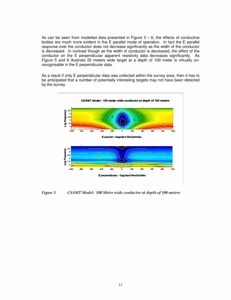
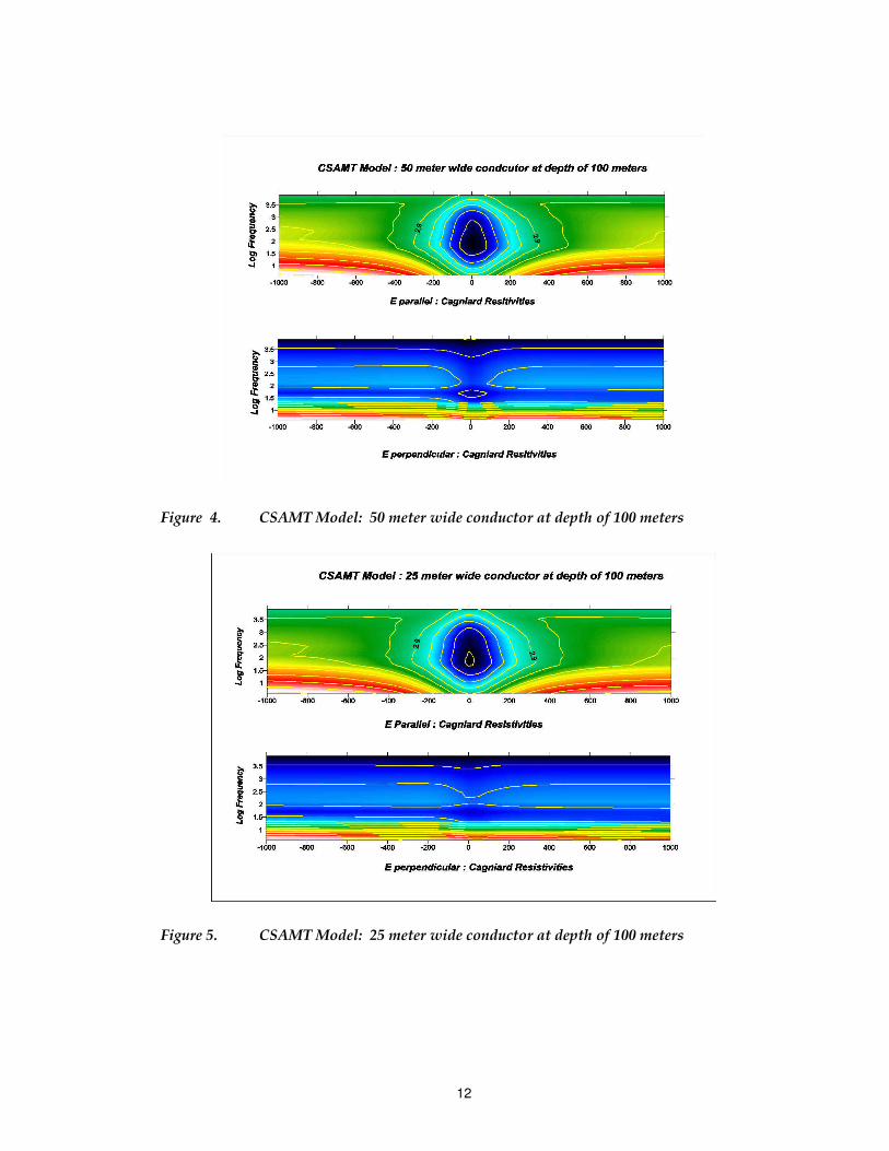
As can be seen from modelled data presented in Figure 3 – 6, the effects of conductive bodies are much more evident in the E parallel mode of operation. In fact the E parallel response over the conductor does not decrease significantly as the width of the conductor is decreased. In contrast though as the width of conductor is decreased, the effect of the conductor on the E perpendicular apparent resistivity data decreases significantly. As Figure 5 and 6 illustrate 25 meters wide target at a depth of 100 meter is virtually un-recognisable in the E perpendicular data.
As a result if only E perpendicular data was collected within the survey area, then it has to be anticipated that a number of potentially interesting targets may not have been detected by the survey.
Figure 3. CSAMT Model: 100 Meter wide conductor at depth of 100 meters
12
Figure 4. CSAMT Model: 50 meter wide conductor at depth of 100 meters
Figure 5. CSAMT Model: 25 meter wide conductor at depth of 100 meters

13
Figure 6. AMT Model: 25 meter wide conductor at depth of 100 meters
6. DISCUSSION OF 1988 CSAMT DATA
The White Spur CSAMT data was collected using frequencies between 2 to 8192 Hz. However because of the high resistivity within the survey area the “notch frequency” or the transition from the far field (AMT mode) zone to near field zone normally occurred at about 512 – 1024 Hz. Considering that beyond this notch frequency the apparent resistivity artefact is such so that the apparent resistivity increases almost linearly with the frequency resulted in some extraordinarily high apparent resistivities at the lower frequencies in many cases in excess of 500,000 ohm meters.
By knowing the location of the transmitter and assuming a relatively simple resistivity distribution between the transmitter’s site and the survey area, it was hoped or anticipated that the effects and difficulties in interpretation due to so many frequencies operating beyond the notch frequency could be alleviated. Using pseudo 1-D smooth models inversion of data was attempted to facilitate this solution. However, numerous attempts to do this failed to give any clearer picture than what can already be deduced through qualitative analysis of the data as was done previously RGC Exploration.
Essentially the overwhelming transition to near zone effects beyond the relatively high notch frequency prevented obtaining any meaningful estimate of the “true” response of the conductive target at the diagnostic and discriminatory responses at low frequencies. Figure 7 and 8, which show just two example of the inversion process, clearly demonstrate that the conductor identified could not be defined sufficiently well to give an estimate of its true quality, rather than just its location.

14
Figure 7. White Spur CSAMT: Line 63800 N
Figure 8. White Spur: Line 611400 N

15
8. CONCLUSION
Analysis inversion and modelling of 1998 CSAMT data has demonstrates that relatively high notch frequency for the survey data prevents a clear definition of the conductive targets quality. As a result the CSAMT data can only be interpreted in a qualitative sense which gives the target location by not necessarily its conductivity thickness product or intrinsic resistivity (conductivity).
Considering that the 1998 CSAMT data was only collected in E perpendicular mode of operation leads to the conclusion that a number of potentially interesting conductive targets whose width (thickness) is less than it’s depth to top would not have been detected by the survey.