By Authority Of - Public.Resource.Org · tr2 August 31, 1999 – UL 1995. UL will attempt to answer...
190
By Authority Of THE UNITED STATES OF AMERICA Legally Binding Document By the Authority Vested By Part 5 of the United States Code § 552(a) and Part 1 of the Code of Regulations § 51 the attached document has been duly INCORPORATED BY REFERENCE and shall be considered legally binding upon all citizens and residents of the United States of America. HEED THIS NOTICE : Criminal penalties may apply for noncompliance. Official Incorporator : THE EXECUTIVE DIRECTOR OFFICE OF THE FEDERAL REGISTER WASHINGTON, D.C. Document Name: CFR Section(s): Standards Body: e
Transcript of By Authority Of - Public.Resource.Org · tr2 August 31, 1999 – UL 1995. UL will attempt to answer...

By Authority OfTHE UNITED STATES OF AMERICA
Legally Binding Document
By the Authority Vested By Part 5 of the United States Code § 552(a) and Part 1 of the Code of Regulations § 51 the attached document has been duly INCORPORATED BY REFERENCE and shall be considered legally binding upon all citizens and residents of the United States of America. HEED THIS NOTICE: Criminal penalties may apply for noncompliance.
Official Incorporator:THE EXECUTIVE DIRECTOROFFICE OF THE FEDERAL REGISTERWASHINGTON, D.C.
Document Name:
CFR Section(s):
Standards Body:
e
carl
Typewritten Text
UL 1995: Heating and Cooling Equipment, Second Edition, with 1999 revisions
carl
Typewritten Text
24 CFR 3280.4
carl
Typewritten Text
Underwriters Laboratories


UL 1995
ISBN 1-55989-888-7
Heating and Cooling Equipment


August 31, 1999 – UL 1995 tr1
Underwriters Laboratories Inc. (UL)333 Pfingsten RoadNorthbrook, IL 60062-2096
UL Standard for Safety forHeating and Cooling Equipment, UL 1995
Second Edition, Dated September 29, 1995
Revisions: This Standard contains revisions through and including August 31, 1999.
The revisions dated August 31, 1999 include a reprinted title page (page 1) for this Standard.
As indicated on the title page (page 1) this UL Standard For Safety is an American National Standard. Attentionis directed to the note on the title page of this Standard outlining the procedures to be followed to retain theapproved text of this ANSI/UL Standard.
As indicated on the title page (page 1), this UL Standard for Safety has been adopted by the Department ofDefense.
The master for this Standard at UL's Northbrook Office is the official document insofar as it relates to a ULservice and the compliance of a product with respect to the requirements for that product and service, or if thereare questions regarding the accuracy of this Standard.
UL's Standards for Safety are copyrighted by UL. Neither a printed copy of a Standard, nor the distributiondiskette for a Standard-on-Diskette and the file for the Standard on the distribution diskette should be alteredin any way. All of UL's Standards and all copyrights, ownerships, and rights regarding those Standards shallremain the sole and exclusive property of UL.
All rights reserved. No part of this publication may be reproduced, stored in a retrieval system, or transmittedin any form by any means, electronic, mechanical photocopying, recording, or otherwise without priorpermission of UL.
Revisions of UL Standards for Safety are issued from time to time. A UL Standard for Safety is current only ifit incorporates the most recently adopted revisions.
UL provides this Standard "as is" without warranty of any kind, either expressed or implied, including but notlimited to, the implied warranties of merchantability or fitness for any purpose.
In no event will UL be liable for any special, incidental, consequential, indirect or similar damages, includingloss of profits, lost savings, loss of data, or any other damages arising out of the use of or the inability to usethis Standard, even if UL or an authorized UL representative has been advised of the possibility of suchdamage. In no event shall UL's liability for any damage ever exceed the price paid for this Standard, regardlessof the form of the claim.

tr2 August 31, 1999 – UL 1995
UL will attempt to answer support requests concerning WordPerfect, Envoy, and Standards-on-Diskette.However, this support service is offered on a reasonable efforts basis only, and UL may not be able to resolveevery support request. UL supports a Standards-on-Diskette only if it is used under the conditions and operatingsystems for which it is intended. UL’s support policies may change from time-to-time without notification.
UL reserves the right to change the format, presentation, file types and formats, delivery methods and formats,and the like of both its printed and electronic Standards without prior notice.
Standards-on-Diskette purchasers agree to defend, indemnify, and hold UL harmless from and against anyloss, expense, liability, damage, claim, or judgement (including reasonable attorney's fees) resulting from anyerror or deviation introduced while purchaser is storing a Standard-on-Diskette on the purchaser's computersystem.
If a single-user version Standards-on-Diskette was purchased, one copy of this Standard may be stored on thehard disk of a single personal computer, or on a single LAN file-server or the permanent storage device of amultiple-user computer in such a manner that this Standard may only be accessed by one user at a time andfor which there is no possibility of multiple concurrent access. The original distribution diskette should be storedin a safe place.
If a multiple-user version Standards-on-Diskette was purchased, one copy of the Standard may be stored ona single LAN file-server, or on the permanent storage device of a multiple-user computer. The number ofconcurrent users shall not exceed the number of users authorized for the Standards-on-Diskette version. Theoriginal distribution diskette should be stored in a safe place.
Standards-on-Diskette are intended for on-line use, such as for viewing the requirements of a Standard,conducting a word search, and the like. Only one copy of the Standard may be printed from each single-userversion of a Standards-on-Diskette. Only one copy of the Standard may be printed for each authorized userof a multiple-user version of a Standards-on-Diskette. An employee of an organization purchasing a Standard-on-Diskette can make a copy of the page or pages being viewed for their own fair and/or practical internal use.Because of differences in the computer/software/printer setup used by UL and those of Standards-on-Diskettepurchasers, the printed copy obtained by a purchaser may not look exactly like the on-line screen view or theprinted Standard.
The requirements in this Standard are now in effect, except for those paragraphs, sections, tables, figures,and/or other elements of the Standard having future effective dates as indicated in the note following theaffected item. The prior text for requirements that have been revised and that have a future effective date arelocated after the Standard, and are preceded by a "SUPERSEDED REQUIREMENTS" notice.
New product submittals made prior to a specified future effective date will be judged under all of therequirements in this Standard including those requirements with a specified future effective date, unless theapplicant specifically requests that the product be judged under the current requirements. However, if theapplicant elects this option, it should be noted that compliance with all the requirements in this Standard willbe required as a condition of continued Listing and Follow-Up Services after the effective date, andunderstanding of this should be signified in writing.
Copyright 1999 Underwriters Laboratories Inc.

August 31, 1999 – UL 1995 tr3
This Standard consists of pages dated as shown in the following checklist:
Page Date
tr1 – tr4 . . . . . . . . . . . . . . . . . . . . . . . . . . . . . . . . . . . . . . . . . . . . . . . . . . . . . . . . . . . . . . . . . . . . August 31, 19991 . . . . . . . . . . . . . . . . . . . . . . . . . . . . . . . . . . . . . . . . . . . . . September 29, 1995 (Reprinted: August 31, 1999)2 – 6, 6A, 6B, 7 . . . . . . . . . . . . . . . . . . . . . . . . . . . . . . . . . . . . . . . . . . . . . . . . . . . . . . . . . . . . . . . July 31, 19988 . . . . . . . . . . . . . . . . . . . . . . . . . . . . . . . . . . . . . . . . . . . . . . . . . . . . . . . . . . . . . . . . . . . . . September 29, 19959, 10 . . . . . . . . . . . . . . . . . . . . . . . . . . . . . . . . . . . . . . . . . . . . . . . . . . . . . . . . . . . . . . . . . . . . . . . . July 31, 199811, 12 . . . . . . . . . . . . . . . . . . . . . . . . . . . . . . . . . . . . . . . . . . . . . . . . . . . . . . . . . . . . . . . . . September 29, 199513, 14, 14A, 14B . . . . . . . . . . . . . . . . . . . . . . . . . . . . . . . . . . . . . . . . . . . . . . . . . . . . . . . . . . . . . . July 31, 199815 . . . . . . . . . . . . . . . . . . . . . . . . . . . . . . . . . . . . . . . . . . . . . . . . . . . . . . . . . . . . . . . . . . . . September 29, 199516, 16A, 16B . . . . . . . . . . . . . . . . . . . . . . . . . . . . . . . . . . . . . . . . . . . . . . . . . . . . . . . . . . . . . . . . . July 31, 199817, 18 . . . . . . . . . . . . . . . . . . . . . . . . . . . . . . . . . . . . . . . . . . . . . . . . . . . . . . . . . . . . . . . . . September 29, 199519, 20 . . . . . . . . . . . . . . . . . . . . . . . . . . . . . . . . . . . . . . . . . . . . . . . . . . . . . . . . . . . . . . . . . . . . . . . July 31, 199821 . . . . . . . . . . . . . . . . . . . . . . . . . . . . . . . . . . . . . . . . . . . . . . . . . . . . . . . . . . . . . . . . . . . . September 29, 199522 . . . . . . . . . . . . . . . . . . . . . . . . . . . . . . . . . . . . . . . . . . . . . . . . . . . . . . . . . . . . . . . . . . . . . . . . . . July 31, 199823 – 39 . . . . . . . . . . . . . . . . . . . . . . . . . . . . . . . . . . . . . . . . . . . . . . . . . . . . . . . . . . . . . . . . September 29, 199540, 40A, 40B . . . . . . . . . . . . . . . . . . . . . . . . . . . . . . . . . . . . . . . . . . . . . . . . . . . . . . . . . . . . . . . . . July 31, 199841 . . . . . . . . . . . . . . . . . . . . . . . . . . . . . . . . . . . . . . . . . . . . . . . . . . . . . . . . . . . . . . . . . . . . September 29, 199542, 42A, 42B, 43, 44, 44A, 44B, 45 . . . . . . . . . . . . . . . . . . . . . . . . . . . . . . . . . . . . . . . . . . . . . . . July 31, 199846 . . . . . . . . . . . . . . . . . . . . . . . . . . . . . . . . . . . . . . . . . . . . . . . . . . . . . . . . . . . . . . . . . . . . September 29, 199547, 48, 48A, 48B, 49 – 52, 52A, 52B . . . . . . . . . . . . . . . . . . . . . . . . . . . . . . . . . . . . . . . . . . . . . . July 31, 199853 – 56 . . . . . . . . . . . . . . . . . . . . . . . . . . . . . . . . . . . . . . . . . . . . . . . . . . . . . . . . . . . . . . . . September 29, 199557 . . . . . . . . . . . . . . . . . . . . . . . . . . . . . . . . . . . . . . . . . . . . . . . . . . . . . . . . . . . . . . . . . . . . . . . . . . July 31, 199858, 59 . . . . . . . . . . . . . . . . . . . . . . . . . . . . . . . . . . . . . . . . . . . . . . . . . . . . . . . . . . . . . . . . September 29, 199560, 60A, 60B . . . . . . . . . . . . . . . . . . . . . . . . . . . . . . . . . . . . . . . . . . . . . . . . . . . . . . . . . . . . . . . . . July 31, 199861 – 63 . . . . . . . . . . . . . . . . . . . . . . . . . . . . . . . . . . . . . . . . . . . . . . . . . . . . . . . . . . . . . . . . September 29, 199564, 64A, 64B . . . . . . . . . . . . . . . . . . . . . . . . . . . . . . . . . . . . . . . . . . . . . . . . . . . . . . . . . . . . . . . . . July 31, 199865 . . . . . . . . . . . . . . . . . . . . . . . . . . . . . . . . . . . . . . . . . . . . . . . . . . . . . . . . . . . . . . . . . . . . September 29, 199566, 66A, 66B . . . . . . . . . . . . . . . . . . . . . . . . . . . . . . . . . . . . . . . . . . . . . . . . . . . . . . . . . . . . . . . . . July 31, 199867 – 71 . . . . . . . . . . . . . . . . . . . . . . . . . . . . . . . . . . . . . . . . . . . . . . . . . . . . . . . . . . . . . . . . September 29, 199572, 72A, 72B, 73, 74, 74A, 74B, 75, 76 . . . . . . . . . . . . . . . . . . . . . . . . . . . . . . . . . . . . . . . . . . . . July 31, 199877 . . . . . . . . . . . . . . . . . . . . . . . . . . . . . . . . . . . . . . . . . . . . . . . . . . . . . . . . . . . . . . . . . . . . September 29, 199578, 78A, 78B . . . . . . . . . . . . . . . . . . . . . . . . . . . . . . . . . . . . . . . . . . . . . . . . . . . . . . . . . . . . . . . . . July 31, 199879 . . . . . . . . . . . . . . . . . . . . . . . . . . . . . . . . . . . . . . . . . . . . . . . . . . . . . . . . . . . . . . . . . . . . September 29, 199580, 80A, 80B . . . . . . . . . . . . . . . . . . . . . . . . . . . . . . . . . . . . . . . . . . . . . . . . . . . . . . . . . . . . . . . . . July 31, 199881, 82 . . . . . . . . . . . . . . . . . . . . . . . . . . . . . . . . . . . . . . . . . . . . . . . . . . . . . . . . . . . . . . . . . September 29, 199583, 84, 84A, 84B . . . . . . . . . . . . . . . . . . . . . . . . . . . . . . . . . . . . . . . . . . . . . . . . . . . . . . . . . . . . . . July 31, 199885 – 93 . . . . . . . . . . . . . . . . . . . . . . . . . . . . . . . . . . . . . . . . . . . . . . . . . . . . . . . . . . . . . . . . September 29, 199594, 95 . . . . . . . . . . . . . . . . . . . . . . . . . . . . . . . . . . . . . . . . . . . . . . . . . . . . . . . . . . . . . . . . . . . . . . . July 31, 199896 – 98 . . . . . . . . . . . . . . . . . . . . . . . . . . . . . . . . . . . . . . . . . . . . . . . . . . . . . . . . . . . . . . . . September 29, 199599, 100, 100A, 100B . . . . . . . . . . . . . . . . . . . . . . . . . . . . . . . . . . . . . . . . . . . . . . . . . . . . . . . . . . . July 31, 1998101, 102 . . . . . . . . . . . . . . . . . . . . . . . . . . . . . . . . . . . . . . . . . . . . . . . . . . . . . . . . . . . . . . . September 29, 1995103 . . . . . . . . . . . . . . . . . . . . . . . . . . . . . . . . . . . . . . . . . . . . . . . . . . . . . . . . . . . . . . . . . . . . . February 28, 1997104 – 106 . . . . . . . . . . . . . . . . . . . . . . . . . . . . . . . . . . . . . . . . . . . . . . . . . . . . . . . . . . . . . . . . . . . . July 31, 1998107, 108 . . . . . . . . . . . . . . . . . . . . . . . . . . . . . . . . . . . . . . . . . . . . . . . . . . . . . . . . . . . . . . . September 29, 1995
tr4 August 31, 1999 – UL 1995
109 . . . . . . . . . . . . . . . . . . . . . . . . . . . . . . . . . . . . . . . . . . . . . . . . . . . . . . . . . . . . . . . . . . . . . . . . . July 31, 1998110 – 116 . . . . . . . . . . . . . . . . . . . . . . . . . . . . . . . . . . . . . . . . . . . . . . . . . . . . . . . . . . . . . . September 29, 1995117 – 119 . . . . . . . . . . . . . . . . . . . . . . . . . . . . . . . . . . . . . . . . . . . . . . . . . . . . . . . . . . . . . . . . . . . . July 31, 1998120 . . . . . . . . . . . . . . . . . . . . . . . . . . . . . . . . . . . . . . . . . . . . . . . . . . . . . . . . . . . . . . . . . . . September 29, 1995121, 122, 122A, 122B . . . . . . . . . . . . . . . . . . . . . . . . . . . . . . . . . . . . . . . . . . . . . . . . . . . . . . . . . . July 31, 1998123 – 125 . . . . . . . . . . . . . . . . . . . . . . . . . . . . . . . . . . . . . . . . . . . . . . . . . . . . . . . . . . . . . . September 29, 1995126, 126A, 126B, 127, 128, 128A, 128B, 129, 130, 130A, 130B, 131, 132 . . . . . . . . . . . . . . . . July 31, 1998133 . . . . . . . . . . . . . . . . . . . . . . . . . . . . . . . . . . . . . . . . . . . . . . . . . . . . . . . . . . . . . . . . . . . . . February 28, 1997134 – 140 . . . . . . . . . . . . . . . . . . . . . . . . . . . . . . . . . . . . . . . . . . . . . . . . . . . . . . . . . . . . . . September 29, 1995

Canadian Standards Association Underwriters Laboratories Inc.CAN/CSA-C22.2 No. 236-95 UL 1995Second Edition Second Edition
Heating and Cooling Equipment
September 29, 1995
(Title Page Reprinted: August 31, 1999)
ANSI/UL 1995-1999
(approved August 1999)
Commitment for AmendmentsThis Standard is issued jointly by Canadian Standards Association and Underwriters LaboratoriesIncorporated. Amendments to this Standard will be made only after processing according to the Standardswriting procedures by both Canadian Standards Association and Underwriters Laboratories Incorporated.
ISSN 0317-5669
Copyright © 1995 Canadian StandardsAssociationAll rights reserved. No part of this publicationmay be reproduced in any form, in an electronicretrieval system or otherwise, without the prior ISBN 1-55989-888-7permission of the publisher.
Approved as ANSI/UL 1995-1999, February 2, 1999
Approval as an American National Standard(ANSI) covers the numbered clauses on pagesdated September 29, 1995. These pages shouldnot be discarded when revised or additionalpages are issued if it is desired to retain the ANSIapproved text. However, pages dated July 31,1998 are not included as part of the ANSIapproved text.
The U.S Department of Defense (DoD) hasadopted UL 1995 on March 9, 1992. Thepublication of revised pages or a new edition ofthis Standard will not invalidate the DoD adoption.
Copyright © 1990, 1999 UnderwritersLaboratories Incorporated

July 31, 1998 CSA-C22.2 No. 236 Ç UL 1995 3
ContentsPreface . . . . . . . . . . . . . . . . . . . . . . . . . . . . . . . . . . . . . . . . . . . . . . . . . . . . . . . . . . . . . . . . . . . . . . . . . . . . . . . 8
Foreword (CSA) . . . . . . . . . . . . . . . . . . . . . . . . . . . . . . . . . . . . . . . . . . . . . . . . . . . . . . . . . . . . . . . . . . . . . . . 10
Foreword (UL) . . . . . . . . . . . . . . . . . . . . . . . . . . . . . . . . . . . . . . . . . . . . . . . . . . . . . . . . . . . . . . . . . . . . . . . . 11
1 Scope . . . . . . . . . . . . . . . . . . . . . . . . . . . . . . . . . . . . . . . . . . . . . . . . . . . . . . . . . . . . . . . . . . . . . . . . . . . 12
2 Definitions . . . . . . . . . . . . . . . . . . . . . . . . . . . . . . . . . . . . . . . . . . . . . . . . . . . . . . . . . . . . . . . . . . . . . . . 14
3 Reference publications . . . . . . . . . . . . . . . . . . . . . . . . . . . . . . . . . . . . . . . . . . . . . . . . . . . . . . . . . . . . 17
4 Installation and operating instructions . . . . . . . . . . . . . . . . . . . . . . . . . . . . . . . . . . . . . . . . . . . . . . 17
CONSTRUCTION . . . . . . . . . . . . . . . . . . . . . . . . . . . . . . . . . . . . . . . . . . . . . . . . . . . . . . . . . . . . . . . . . . . 18
5 Enclosures . . . . . . . . . . . . . . . . . . . . . . . . . . . . . . . . . . . . . . . . . . . . . . . . . . . . . . . . . . . . . . . . . . . . . . 18Polymeric materials other than enclosures . . . . . . . . . . . . . . . . . . . . . . . . . . . . . . . . . . . . . . . . . . . . . . . 19General . . . . . . . . . . . . . . . . . . . . . . . . . . . . . . . . . . . . . . . . . . . . . . . . . . . . . . . . . . . . . . . . . . . . . . . . . . . . 19Isolation from ignition sources . . . . . . . . . . . . . . . . . . . . . . . . . . . . . . . . . . . . . . . . . . . . . . . . . . . . . . . . . . 20
6 Thickness of sheet metal enclosures for uninsulated live parts . . . . . . . . . . . . . . . . . . . . . . . . . 22
7 Openings in enclosures . . . . . . . . . . . . . . . . . . . . . . . . . . . . . . . . . . . . . . . . . . . . . . . . . . . . . . . . . . . 26
8 Enclosures, doors, and covers . . . . . . . . . . . . . . . . . . . . . . . . . . . . . . . . . . . . . . . . . . . . . . . . . . . . . 28
9 Accessibility of parts . . . . . . . . . . . . . . . . . . . . . . . . . . . . . . . . . . . . . . . . . . . . . . . . . . . . . . . . . . . . . . 28
10 Assembly . . . . . . . . . . . . . . . . . . . . . . . . . . . . . . . . . . . . . . . . . . . . . . . . . . . . . . . . . . . . . . . . . . . . . . . 29
11 Mechanical protection . . . . . . . . . . . . . . . . . . . . . . . . . . . . . . . . . . . . . . . . . . . . . . . . . . . . . . . . . . . . 30
12 Outdoor use equipment . . . . . . . . . . . . . . . . . . . . . . . . . . . . . . . . . . . . . . . . . . . . . . . . . . . . . . . . . . 32
13 Enclosures, outdoor use . . . . . . . . . . . . . . . . . . . . . . . . . . . . . . . . . . . . . . . . . . . . . . . . . . . . . . . . . 34
14 Field wiring connections, outdoor use equipment . . . . . . . . . . . . . . . . . . . . . . . . . . . . . . . . . . . . 34

4 CSA-C22.2 No. 236 Ç UL 1995 July 31, 1998
15 Mechanical assembly . . . . . . . . . . . . . . . . . . . . . . . . . . . . . . . . . . . . . . . . . . . . . . . . . . . . . . . . . . . . 35
16 Auxiliary devices . . . . . . . . . . . . . . . . . . . . . . . . . . . . . . . . . . . . . . . . . . . . . . . . . . . . . . . . . . . . . . . . 36
17 Connection to power supply . . . . . . . . . . . . . . . . . . . . . . . . . . . . . . . . . . . . . . . . . . . . . . . . . . . . . . 36
18 Thermal insulation and air filters . . . . . . . . . . . . . . . . . . . . . . . . . . . . . . . . . . . . . . . . . . . . . . . . . . 40
19 Terminal parts and leads for field wiring connections . . . . . . . . . . . . . . . . . . . . . . . . . . . . . . . . 41General . . . . . . . . . . . . . . . . . . . . . . . . . . . . . . . . . . . . . . . . . . . . . . . . . . . . . . . . . . . . . . . . . . . . . . . . . . . . 41Hazardous Voltage Circuits . . . . . . . . . . . . . . . . . . . . . . . . . . . . . . . . . . . . . . . . . . . . . . . . . . . . . . . . . . . . 42Extra-Low-Voltage Circuits . . . . . . . . . . . . . . . . . . . . . . . . . . . . . . . . . . . . . . . . . . . . . . . . . . . . . . . . . . . 44A
20 Internal wiring . . . . . . . . . . . . . . . . . . . . . . . . . . . . . . . . . . . . . . . . . . . . . . . . . . . . . . . . . . . . . . . . . . . 45
21 Separation of circuits . . . . . . . . . . . . . . . . . . . . . . . . . . . . . . . . . . . . . . . . . . . . . . . . . . . . . . . . . . . . 49
22 Electrical insulation . . . . . . . . . . . . . . . . . . . . . . . . . . . . . . . . . . . . . . . . . . . . . . . . . . . . . . . . . . . . . . 50
23 Motors . . . . . . . . . . . . . . . . . . . . . . . . . . . . . . . . . . . . . . . . . . . . . . . . . . . . . . . . . . . . . . . . . . . . . . . . . 50Motor Enclosures . . . . . . . . . . . . . . . . . . . . . . . . . . . . . . . . . . . . . . . . . . . . . . . . . . . . . . . . . . . . . . . . . . . . 50Motor Overload Protection . . . . . . . . . . . . . . . . . . . . . . . . . . . . . . . . . . . . . . . . . . . . . . . . . . . . . . . . . . . . 52AShort Circuit Protection . . . . . . . . . . . . . . . . . . . . . . . . . . . . . . . . . . . . . . . . . . . . . . . . . . . . . . . . . . . . . . . 54
24 Grounding and bonding . . . . . . . . . . . . . . . . . . . . . . . . . . . . . . . . . . . . . . . . . . . . . . . . . . . . . . . . . . 55
25 Mounting of components . . . . . . . . . . . . . . . . . . . . . . . . . . . . . . . . . . . . . . . . . . . . . . . . . . . . . . . . . 56
26 Switches and controllers . . . . . . . . . . . . . . . . . . . . . . . . . . . . . . . . . . . . . . . . . . . . . . . . . . . . . . . . . 57
27 Transformers . . . . . . . . . . . . . . . . . . . . . . . . . . . . . . . . . . . . . . . . . . . . . . . . . . . . . . . . . . . . . . . . . . . 59
28 Capacitors . . . . . . . . . . . . . . . . . . . . . . . . . . . . . . . . . . . . . . . . . . . . . . . . . . . . . . . . . . . . . . . . . . . . . . 61
29 Electric crankcase heaters . . . . . . . . . . . . . . . . . . . . . . . . . . . . . . . . . . . . . . . . . . . . . . . . . . . . . . . 61
30 Electric heaters . . . . . . . . . . . . . . . . . . . . . . . . . . . . . . . . . . . . . . . . . . . . . . . . . . . . . . . . . . . . . . . . . 62
31 Control circuits . . . . . . . . . . . . . . . . . . . . . . . . . . . . . . . . . . . . . . . . . . . . . . . . . . . . . . . . . . . . . . . . . 65
32 Spacings . . . . . . . . . . . . . . . . . . . . . . . . . . . . . . . . . . . . . . . . . . . . . . . . . . . . . . . . . . . . . . . . . . . . . . . 67Hazardous Voltage Circuits . . . . . . . . . . . . . . . . . . . . . . . . . . . . . . . . . . . . . . . . . . . . . . . . . . . . . . . . . . . . 67Extra-Low-Voltage Circuits . . . . . . . . . . . . . . . . . . . . . . . . . . . . . . . . . . . . . . . . . . . . . . . . . . . . . . . . . . . . 70

July 31, 1998 CSA-C22.2 No. 236 Ç UL 1995 5
33 Refrigerant, hot water, and steam coils . . . . . . . . . . . . . . . . . . . . . . . . . . . . . . . . . . . . . . . . . . . . . 71General . . . . . . . . . . . . . . . . . . . . . . . . . . . . . . . . . . . . . . . . . . . . . . . . . . . . . . . . . . . . . . . . . . . . . . . . . . . . 71Refrigerant Pressure Relief . . . . . . . . . . . . . . . . . . . . . . . . . . . . . . . . . . . . . . . . . . . . . . . . . . . . . . . . . . . . 73Refrigerant Pressure-Limiting Device . . . . . . . . . . . . . . . . . . . . . . . . . . . . . . . . . . . . . . . . . . . . . . . . . . . . 75
34 Heat pump water heating equipment . . . . . . . . . . . . . . . . . . . . . . . . . . . . . . . . . . . . . . . . . . . . . . . 76General . . . . . . . . . . . . . . . . . . . . . . . . . . . . . . . . . . . . . . . . . . . . . . . . . . . . . . . . . . . . . . . . . . . . . . . . . . . . 76Heater Exchanger . . . . . . . . . . . . . . . . . . . . . . . . . . . . . . . . . . . . . . . . . . . . . . . . . . . . . . . . . . . . . . . . . . . 76Storage Tank . . . . . . . . . . . . . . . . . . . . . . . . . . . . . . . . . . . . . . . . . . . . . . . . . . . . . . . . . . . . . . . . . . . . . . . 77Water Temperature Control . . . . . . . . . . . . . . . . . . . . . . . . . . . . . . . . . . . . . . . . . . . . . . . . . . . . . . . . . . . 77
UNIT MARKINGS . . . . . . . . . . . . . . . . . . . . . . . . . . . . . . . . . . . . . . . . . . . . . . . . . . . . . . . . . . . . . . . . . . . 77
35 General . . . . . . . . . . . . . . . . . . . . . . . . . . . . . . . . . . . . . . . . . . . . . . . . . . . . . . . . . . . . . . . . . . . . . . . . 77
36 Equipment markings . . . . . . . . . . . . . . . . . . . . . . . . . . . . . . . . . . . . . . . . . . . . . . . . . . . . . . . . . . . . . 78Determination of Rating . . . . . . . . . . . . . . . . . . . . . . . . . . . . . . . . . . . . . . . . . . . . . . . . . . . . . . . . . . . . . . . 81Minimum Circuit Ampacity . . . . . . . . . . . . . . . . . . . . . . . . . . . . . . . . . . . . . . . . . . . . . . . . . . . . . . . . . . . . . 81Rating of Overcurrent Protective Devices . . . . . . . . . . . . . . . . . . . . . . . . . . . . . . . . . . . . . . . . . . . . . . . . . 82
37 Other markings . . . . . . . . . . . . . . . . . . . . . . . . . . . . . . . . . . . . . . . . . . . . . . . . . . . . . . . . . . . . . . . . . 84
TESTS . . . . . . . . . . . . . . . . . . . . . . . . . . . . . . . . . . . . . . . . . . . . . . . . . . . . . . . . . . . . . . . . . . . . . . . . . . . . 85
38 General test parameters . . . . . . . . . . . . . . . . . . . . . . . . . . . . . . . . . . . . . . . . . . . . . . . . . . . . . . . . . . 85Test Voltage . . . . . . . . . . . . . . . . . . . . . . . . . . . . . . . . . . . . . . . . . . . . . . . . . . . . . . . . . . . . . . . . . . . . . . . . 94Air Flow . . . . . . . . . . . . . . . . . . . . . . . . . . . . . . . . . . . . . . . . . . . . . . . . . . . . . . . . . . . . . . . . . . . . . . . . . . . . 94Static Pressure . . . . . . . . . . . . . . . . . . . . . . . . . . . . . . . . . . . . . . . . . . . . . . . . . . . . . . . . . . . . . . . . . . . . . . 95Unit Setup . . . . . . . . . . . . . . . . . . . . . . . . . . . . . . . . . . . . . . . . . . . . . . . . . . . . . . . . . . . . . . . . . . . . . . . . . . 96Test Enclosure . . . . . . . . . . . . . . . . . . . . . . . . . . . . . . . . . . . . . . . . . . . . . . . . . . . . . . . . . . . . . . . . . . . . . . 99Instrumentation . . . . . . . . . . . . . . . . . . . . . . . . . . . . . . . . . . . . . . . . . . . . . . . . . . . . . . . . . . . . . . . . . . . . 100
39 Input test . . . . . . . . . . . . . . . . . . . . . . . . . . . . . . . . . . . . . . . . . . . . . . . . . . . . . . . . . . . . . . . . . . . . . . 100Circuits-Other than Electric Heaters . . . . . . . . . . . . . . . . . . . . . . . . . . . . . . . . . . . . . . . . . . . . . . . . . . . . 100Electric Heater Circuits . . . . . . . . . . . . . . . . . . . . . . . . . . . . . . . . . . . . . . . . . . . . . . . . . . . . . . . . . . . . . . 100
40 Temperature operation test–without any supplementary heating means . . . . . . . . . . . . . . 100A
41 Temperature operation tests–with hot water or steam heating . . . . . . . . . . . . . . . . . . . . . . . . 101
42 Cooling operation test–temperature and pressure . . . . . . . . . . . . . . . . . . . . . . . . . . . . . . . . . . 101

6 CSA-C22.2 No. 236 Ç UL 1995 July 31, 1998
43 Heating operation test–temperature and pressure . . . . . . . . . . . . . . . . . . . . . . . . . . . . . . . . . . 102
44 Abnormal temperature and pressure tests–refrigerant heat only . . . . . . . . . . . . . . . . . . . . . . 102Indoor Fan Failure and Water Failure . . . . . . . . . . . . . . . . . . . . . . . . . . . . . . . . . . . . . . . . . . . . . . . . . . . 102
45 Electric heater tests . . . . . . . . . . . . . . . . . . . . . . . . . . . . . . . . . . . . . . . . . . . . . . . . . . . . . . . . . . . . 103General . . . . . . . . . . . . . . . . . . . . . . . . . . . . . . . . . . . . . . . . . . . . . . . . . . . . . . . . . . . . . . . . . . . . . . . . . . . 103Continuity of Operation-Simultaneous Electric Resistance Heat and Refrigerant Heat . . . . . . . . . . . . . . . . . . . . . . . . . . . . . . . . . . . . . . . . . . . . . . . . . . . . . . . . . . . . . . . . 103Continuity of Operation-Electric Resistance Heat Only . . . . . . . . . . . . . . . . . . . . . . . . . . . . . . . . . . . . . 103Limit Control Cutout Test-Simultaneous Electric ResistanceHeat and Refrigerant Heat . . . . . . . . . . . . . . . . . . . . . . . . . . . . . . . . . . . . . . . . . . . . . . . . . . . . . . . . . . . 104Limit Control Cutout Test-Electric Resistance Heat Only . . . . . . . . . . . . . . . . . . . . . . . . . . . . . . . . . . . 104Heating Operation Test-Unit with Electric Resistance Heaters . . . . . . . . . . . . . . . . . . . . . . . . . . . . . . . 104
46 Abnormal temperature and pressure tests . . . . . . . . . . . . . . . . . . . . . . . . . . . . . . . . . . . . . . . . . 105General . . . . . . . . . . . . . . . . . . . . . . . . . . . . . . . . . . . . . . . . . . . . . . . . . . . . . . . . . . . . . . . . . . . . . . . . . . . 105Restricted Inlet . . . . . . . . . . . . . . . . . . . . . . . . . . . . . . . . . . . . . . . . . . . . . . . . . . . . . . . . . . . . . . . . . . . . . 106Fan Failure . . . . . . . . . . . . . . . . . . . . . . . . . . . . . . . . . . . . . . . . . . . . . . . . . . . . . . . . . . . . . . . . . . . . . . . . 106Blocked Outlet . . . . . . . . . . . . . . . . . . . . . . . . . . . . . . . . . . . . . . . . . . . . . . . . . . . . . . . . . . . . . . . . . . . . . 106Curtain Drape . . . . . . . . . . . . . . . . . . . . . . . . . . . . . . . . . . . . . . . . . . . . . . . . . . . . . . . . . . . . . . . . . . . . . . 106
47 Backup Protection Tests . . . . . . . . . . . . . . . . . . . . . . . . . . . . . . . . . . . . . . . . . . . . . . . . . . . . . . . . 107General . . . . . . . . . . . . . . . . . . . . . . . . . . . . . . . . . . . . . . . . . . . . . . . . . . . . . . . . . . . . . . . . . . . . . . . . . . . 107Restricted Inlet . . . . . . . . . . . . . . . . . . . . . . . . . . . . . . . . . . . . . . . . . . . . . . . . . . . . . . . . . . . . . . . . . . . . . 107Fan Failure . . . . . . . . . . . . . . . . . . . . . . . . . . . . . . . . . . . . . . . . . . . . . . . . . . . . . . . . . . . . . . . . . . . . . . . . 107Blocked Outlet . . . . . . . . . . . . . . . . . . . . . . . . . . . . . . . . . . . . . . . . . . . . . . . . . . . . . . . . . . . . . . . . . . . . . 107
48 Fan delay test–duct-connected downflow and horizontal units . . . . . . . . . . . . . . . . . . . . . . . 108
49 Control System Failure Test . . . . . . . . . . . . . . . . . . . . . . . . . . . . . . . . . . . . . . . . . . . . . . . . . . . . . 108
50 Fan motor failure test . . . . . . . . . . . . . . . . . . . . . . . . . . . . . . . . . . . . . . . . . . . . . . . . . . . . . . . . . . . 109
51 Condenser water failure test . . . . . . . . . . . . . . . . . . . . . . . . . . . . . . . . . . . . . . . . . . . . . . . . . . . . . 109
52 Dielectric voltage–withstand test . . . . . . . . . . . . . . . . . . . . . . . . . . . . . . . . . . . . . . . . . . . . . . . . 109
53 Condensate drain blockage test . . . . . . . . . . . . . . . . . . . . . . . . . . . . . . . . . . . . . . . . . . . . . . . . . . 110
54 Loading Test . . . . . . . . . . . . . . . . . . . . . . . . . . . . . . . . . . . . . . . . . . . . . . . . . . . . . . . . . . . . . . . . . . . 110

July 31, 1998 CSA-C22.2 No. 236 Ç UL 1995 6A
55 Limited short-circuit test . . . . . . . . . . . . . . . . . . . . . . . . . . . . . . . . . . . . . . . . . . . . . . . . . . . . . . . . 111
56 Transformer–burnout test . . . . . . . . . . . . . . . . . . . . . . . . . . . . . . . . . . . . . . . . . . . . . . . . . . . . . . . 113
57 Transformer–overload test . . . . . . . . . . . . . . . . . . . . . . . . . . . . . . . . . . . . . . . . . . . . . . . . . . . . . . 113
58 Rain test . . . . . . . . . . . . . . . . . . . . . . . . . . . . . . . . . . . . . . . . . . . . . . . . . . . . . . . . . . . . . . . . . . . . . . 114
59 Accelerated aging tests . . . . . . . . . . . . . . . . . . . . . . . . . . . . . . . . . . . . . . . . . . . . . . . . . . . . . . . . . 117Gaskets . . . . . . . . . . . . . . . . . . . . . . . . . . . . . . . . . . . . . . . . . . . . . . . . . . . . . . . . . . . . . . . . . . . . . . . . . . 117Polymeric Materials . . . . . . . . . . . . . . . . . . . . . . . . . . . . . . . . . . . . . . . . . . . . . . . . . . . . . . . . . . . . . . . . . 119
60 Impact test . . . . . . . . . . . . . . . . . . . . . . . . . . . . . . . . . . . . . . . . . . . . . . . . . . . . . . . . . . . . . . . . . . . . 120
61 Strength tests . . . . . . . . . . . . . . . . . . . . . . . . . . . . . . . . . . . . . . . . . . . . . . . . . . . . . . . . . . . . . . . . . . 121
61A Fatigue test analysis . . . . . . . . . . . . . . . . . . . . . . . . . . . . . . . . . . . . . . . . . . . . . . . . . . . . . . . . . . . 121General . . . . . . . . . . . . . . . . . . . . . . . . . . . . . . . . . . . . . . . . . . . . . . . . . . . . . . . . . . . . . . . . . . . . . . . . . . . 121Test Specification . . . . . . . . . . . . . . . . . . . . . . . . . . . . . . . . . . . . . . . . . . . . . . . . . . . . . . . . . . . . . . . . . . . 121Material Specifications . . . . . . . . . . . . . . . . . . . . . . . . . . . . . . . . . . . . . . . . . . . . . . . . . . . . . . . . . . . . . . . 122General Test Specification . . . . . . . . . . . . . . . . . . . . . . . . . . . . . . . . . . . . . . . . . . . . . . . . . . . . . . . . . . . 122Test Method . . . . . . . . . . . . . . . . . . . . . . . . . . . . . . . . . . . . . . . . . . . . . . . . . . . . . . . . . . . . . . . . . . . . . . . 122Test Parameters . . . . . . . . . . . . . . . . . . . . . . . . . . . . . . . . . . . . . . . . . . . . . . . . . . . . . . . . . . . . . . . . . . 122ACycle Test Pressure Specification . . . . . . . . . . . . . . . . . . . . . . . . . . . . . . . . . . . . . . . . . . . . . . . . . . . . . 122A
62 Rupture member tests . . . . . . . . . . . . . . . . . . . . . . . . . . . . . . . . . . . . . . . . . . . . . . . . . . . . . . . . . 122A
63 Fusible plug test . . . . . . . . . . . . . . . . . . . . . . . . . . . . . . . . . . . . . . . . . . . . . . . . . . . . . . . . . . . . . . 122B
64 Heat pump water heating equipment . . . . . . . . . . . . . . . . . . . . . . . . . . . . . . . . . . . . . . . . . . . . . 122BInput Test . . . . . . . . . . . . . . . . . . . . . . . . . . . . . . . . . . . . . . . . . . . . . . . . . . . . . . . . . . . . . . . . . . . . . . . . 122BNormal Temperature . . . . . . . . . . . . . . . . . . . . . . . . . . . . . . . . . . . . . . . . . . . . . . . . . . . . . . . . . . . . . . . 122BStarting Test . . . . . . . . . . . . . . . . . . . . . . . . . . . . . . . . . . . . . . . . . . . . . . . . . . . . . . . . . . . . . . . . . . . . . . . 123Temperature-Limiting Control Cutout Test . . . . . . . . . . . . . . . . . . . . . . . . . . . . . . . . . . . . . . . . . . . . . . . 123Water Failure Test . . . . . . . . . . . . . . . . . . . . . . . . . . . . . . . . . . . . . . . . . . . . . . . . . . . . . . . . . . . . . . . . . . 124Heat Exchanger Strength Test . . . . . . . . . . . . . . . . . . . . . . . . . . . . . . . . . . . . . . . . . . . . . . . . . . . . . . . . 124
65 Ultraviolet light exposure test . . . . . . . . . . . . . . . . . . . . . . . . . . . . . . . . . . . . . . . . . . . . . . . . . . . . 124
66 Water Exposure and Immersion Test . . . . . . . . . . . . . . . . . . . . . . . . . . . . . . . . . . . . . . . . . . . . . . 124

6B CSA-C22.2 No. 236 Ç UL 1995 July 31, 1998
MANUFACTURING AND PRODUCTION TESTS . . . . . . . . . . . . . . . . . . . . . . . . . . . . . . . . . . . . . . . . . 125
67 Knockout security test . . . . . . . . . . . . . . . . . . . . . . . . . . . . . . . . . . . . . . . . . . . . . . . . . . . . . . . . . . 125
68 Pressure tests for leakage and strength . . . . . . . . . . . . . . . . . . . . . . . . . . . . . . . . . . . . . . . . . . . 125
68A Production Fatigue Tests . . . . . . . . . . . . . . . . . . . . . . . . . . . . . . . . . . . . . . . . . . . . . . . . . . . . . . . 126
69 Production line dielectric voltage-withstand tests . . . . . . . . . . . . . . . . . . . . . . . . . . . . . . . . . . . 126
STANDARDS FOR COMPONENTS . . . . . . . . . . . . . . . . . . . . . . . . . . . . . . . . . . . . . . . . . . . . . . . . . . . 127
70 CSA Standards . . . . . . . . . . . . . . . . . . . . . . . . . . . . . . . . . . . . . . . . . . . . . . . . . . . . . . . . . . . . . . . . . 12771 UL Standards . . . . . . . . . . . . . . . . . . . . . . . . . . . . . . . . . . . . . . . . . . . . . . . . . . . . . . . . . . . . . . . . . . 128A72 Other Standards . . . . . . . . . . . . . . . . . . . . . . . . . . . . . . . . . . . . . . . . . . . . . . . . . . . . . . . . . . . . . . . . 130BAbbreviations . . . . . . . . . . . . . . . . . . . . . . . . . . . . . . . . . . . . . . . . . . . . . . . . . . . . . . . . . . . . . . . . . . . . . . 131
APPENDICES
A Marking Translations . . . . . . . . . . . . . . . . . . . . . . . . . . . . . . . . . . . . . . . . . . . . . . . . . . . . . . . . . . . . . . 133B Hot, Flaming Oil Test and Molten PVC and Copper Test . . . . . . . . . . . . . . . . . . . . . . . . . . . . . . . . . 134
TABLES
5.9.1 Uses of Materials Based on Flammability Classifications . . . . . . . . . . . . . . . . . . . . . . . . . . . . . . . 226.1 Minimum Thickness of Sheet Metal for Electrical Enclosures— Carbon Steel or Stainless Steel . . . . . . . . . . . . . . . . . . . . . . . . . . . . . . . . . . . . . . . . . . . . . . . . . . . . . . . . . . . . . . . . . . . . . . 236.2 Minimum Thickness of Steel Metal for Electrical Enclosures— Aluminum, Copper, or Brass . . . . 246.3 Minimum Thickness of Cast Metal Enclosures for Live Parts . . . . . . . . . . . . . . . . . . . . . . . . . . . . . 2511.1 Clearance from Openings . . . . . . . . . . . . . . . . . . . . . . . . . . . . . . . . . . . . . . . . . . . . . . . . . . . . . . . . 3212.1 Corrosion Protection . . . . . . . . . . . . . . . . . . . . . . . . . . . . . . . . . . . . . . . . . . . . . . . . . . . . . . . . . . . . 3317.1 Knockout or Hole Sizes and Dimensions of Bushings . . . . . . . . . . . . . . . . . . . . . . . . . . . . . . . . . . 3817.2 Trade Size of Conduit . . . . . . . . . . . . . . . . . . . . . . . . . . . . . . . . . . . . . . . . . . . . . . . . . . . . . . . . . . . 3920.1 Wiring Materials Ampacities . . . . . . . . . . . . . . . . . . . . . . . . . . . . . . . . . . . . . . . . . . . . . . . . . . . . . . 4520.2 Typical Wiring Materials . . . . . . . . . . . . . . . . . . . . . . . . . . . . . . . . . . . . . . . . . . . . . . . . . . . . . . . . . 4623.1 Protective Device Activation Level . . . . . . . . . . . . . . . . . . . . . . . . . . . . . . . . . . . . . . . . . . . . . . . . . 5326.1 Ampere Ratings For 3-Phase Compressor Motors . . . . . . . . . . . . . . . . . . . . . . . . . . . . . . . . . . . . 5727.1 Rating of Overcurrent Device . . . . . . . . . . . . . . . . . . . . . . . . . . . . . . . . . . . . . . . . . . . . . . . . . . . . . 6031.1 Overcurrent Protective Device Rating for Control Circuit Conductors . . . . . . . . . . . . . . . . . . . . . 6632.1 Spacings for Hazardous Voltage Circuits . . . . . . . . . . . . . . . . . . . . . . . . . . . . . . . . . . . . . . . . . . . . 6732.2 Minimum Spacings at Locations other than Electric Heating Elements . . . . . . . . . . . . . . . . . . . . 6932.3 Minimum Spacings at Electric Heating Elements . . . . . . . . . . . . . . . . . . . . . . . . . . . . . . . . . . . . . 7033.1 Tubing Wall Thickness . . . . . . . . . . . . . . . . . . . . . . . . . . . . . . . . . . . . . . . . . . . . . . . . . . . . . . . . . . 7138.1 Operation Tests (Units With Compressors) . . . . . . . . . . . . . . . . . . . . . . . . . . . . . . . . . . . . . . . . . . 8738.2 Operation Tests (Units Without Compressors) . . . . . . . . . . . . . . . . . . . . . . . . . . . . . . . . . . . . . . . 8838.3 Polymeric Material Tests . . . . . . . . . . . . . . . . . . . . . . . . . . . . . . . . . . . . . . . . . . . . . . . . . . . . . . . . . 8938.4 Air and Water Temperatures EC (EF) . . . . . . . . . . . . . . . . . . . . . . . . . . . . . . . . . . . . . . . . . . . . . . . 9038.5 Maximum Acceptable Temperatures . . . . . . . . . . . . . . . . . . . . . . . . . . . . . . . . . . . . . . . . . . . . . . . 91

July 31, 1998 CSA-C22.2 No. 236 Ç UL 1995 7
38.6 Test Voltages . . . . . . . . . . . . . . . . . . . . . . . . . . . . . . . . . . . . . . . . . . . . . . . . . . . . . . . . . . . . . . . . . . 9438.7 Operation Conditions; Relation of Total Static Pressure to Total Heat Output . . . . . . . . . . . . . . . 9538.8 Operating Conditions; Relation of Total Static Pressure to Cooling Ratings . . . . . . . . . . . . . . . . 9655.1 Limited Short-Circuit Test Currents . . . . . . . . . . . . . . . . . . . . . . . . . . . . . . . . . . . . . . . . . . . . . . . . 11259.1 Physical Properties for Gaskets . . . . . . . . . . . . . . . . . . . . . . . . . . . . . . . . . . . . . . . . . . . . . . . . . . 11859.2 Accelerated Aging Conditions for Gaskets . . . . . . . . . . . . . . . . . . . . . . . . . . . . . . . . . . . . . . . . . . 11959.3 Accelerated Aging Conditions for Polymeric Materials . . . . . . . . . . . . . . . . . . . . . . . . . . . . . . . . 12068.1 Refrigerant Minimum Design Pressures . . . . . . . . . . . . . . . . . . . . . . . . . . . . . . . . . . . . . . . . . . . . 126
FIGURES
5.9.1 Exposure to Ignition . . . . . . . . . . . . . . . . . . . . . . . . . . . . . . . . . . . . . . . . . . . . . . . . . . . . . . . . . . . . 217.1 Probe (Other than Moving Parts) . . . . . . . . . . . . . . . . . . . . . . . . . . . . . . . . . . . . . . . . . . . . . . . . . . . 267.2 Probe (For Film-Coated Wire) . . . . . . . . . . . . . . . . . . . . . . . . . . . . . . . . . . . . . . . . . . . . . . . . . . . . . 2711.1 Probe (Moving Parts) . . . . . . . . . . . . . . . . . . . . . . . . . . . . . . . . . . . . . . . . . . . . . . . . . . . . . . . . . . . . 3123.1 Location and Extent of Barrier . . . . . . . . . . . . . . . . . . . . . . . . . . . . . . . . . . . . . . . . . . . . . . . . . . . . . 5236.1 Minimum Circuit Ampacity Calculation . . . . . . . . . . . . . . . . . . . . . . . . . . . . . . . . . . . . . . . . . . . . . . 8236.2 Maximum Rating of Overcurrent Protective Device Calculation . . . . . . . . . . . . . . . . . . . . . . . . . . 8338.1 Warm Air Outlet . . . . . . . . . . . . . . . . . . . . . . . . . . . . . . . . . . . . . . . . . . . . . . . . . . . . . . . . . . . . . . . 9858.1 Rain Test Apparatus . . . . . . . . . . . . . . . . . . . . . . . . . . . . . . . . . . . . . . . . . . . . . . . . . . . . . . . . . . . 11558.2 Rain Test Spray Head . . . . . . . . . . . . . . . . . . . . . . . . . . . . . . . . . . . . . . . . . . . . . . . . . . . . . . . . . . 116

8 CSA-C22.2 No. 236 Ç UL 1995 September 29, 1995
Preface
This is the common CSA and UL Standard for Heating and Cooling Equipment. It is the second edition ofCSA C22.2 No. 236 and the second edition of UL 1995. This edition supersedes the previous editionpublished in 1990.
This common Standard was prepared by Canadian Standards Association, Underwriters Laboratories Inc.,and the heating and cooling equipment industry. The efforts and support of the Air Conditioning andRefrigeration Institute (ARI) and the Heating, Refrigerating, and Air Conditioning Institute of Canada (HRAI)are acknowledged.
This Standard addresses safety requirements for various types of heating, air-conditioning, and ventilationequipment.
The following requirements have been added to this second edition:
a) Polymeric Materials (Clauses 5.9, 59.5, and Table 59.3);
b) Internal Wiring (Clause 20.8 (3), (4), and (5));
c) Motor Enclosure (Clause 23 and Figure 23.1);
d) Switches and Controllers (Clauses 26.2(c), 26.18, and Table 26.1);
e) Unit Markings (Clauses 35.1 and 36.3(h), (r));
f) Tests (Table 38.3);
g) Impact Test (Clause 60);
h) Ultraviolet Light Exposure (Clause 65);
i) Appendix B.
This Standard was revised by the CSA Subcommittee of the Technical Committee on Consumer andCommercial Products under the jurisdiction of the CSA Standards Steering Committee on the CanadianElectrical Code, Part II and was formally approved by these Committees; and processed according to themethod of development, revision, and implementation of UL standards for safety.
This Standard will be submitted to the Standards Council of Canada for approval as a National Standard ofCanada and will be submitted to the American National Standards Institute (ANSI) for publication as anAmerican National Standard.
Note – Although the intended primary application of this Standard is stated in its Scope, it is important tonote that it remains the responsibility of the users of the Standard to judge its suitability for their particularpurpose.

July 31, 1998 CSA-C22.2 No. 236 Ç UL 1995 9
UL Effective Date
This standard is now in effect for all products.
CSA Effective DateThe effective date for CSA will be announced through CSA Informs.

10 CSA-C22.2 No. 236 Ç UL 1995 July 31, 1998
Foreword (CSA)
Certification organizations, as accredited by the Standards Council of Canada, have their own criteriaprocedures for certification services. The following paragraphs define CSA Certification policies.
The Canadian Standards Association provides certification services for manufacturers who, under licensefrom CSA, wish to use the appropriate registered CSA Marks on certain products of their manufacture toindicate conformity with CSA Standards.
CSA Certification for a number of products is provided in the interest of maintaining agreed-uponstandards of quality, performance, interchangeability and/or safety, as appropriate. Where applicable,certification may form the basis for acceptance by inspection authorities responsible for enforcement ofregulations. Where feasible, programs will be developed for additional products for which certification isdesired by producers, consumers or other interests.
In performing its functions in accordance with its objectives, CSA does not assume or undertake todischarge any responsibility of the manufacturer or any other party. The opinions and findings of theAssociation represent its professional judgement given with due consideration to the necessity limitations ofpractical operation and state of the art at the time the Standard is processed.
Products in substantial accord with this Standard but which exhibit a minor difference or a new feature maybe deemed to meet the Standard providing the feature or difference is found acceptable utilizingappropriate CSA Certification Division Operating Procedures. Products which comply with this Standardshall not be certified if they are found to have additional features which are inconsistent with the intent of thisStandard. Products shall not be certifiable if they are discovered to contravene applicable Federal laws orregulations.
Testing techniques, test procedures and instrumentation frequently must be prescribed by the CSACertification Division in addition to the technical requirements contained in Standards of CSA. In addition tomarkings specified in the Standard the CSA Certification and Testing Division may require special cautions,markings and instructions that are not specified by the Standard.
Some tests required by CSA Standards may be inherently hazardous. The Association neither assumesnor accepts any responsibility for any injury or damage that may occur during or as the result of tests,wherever performed, whether performed in whole or in part by the manufacturer or the Association, andwhether or not any equipment, facility or personnel for in connection with the test is furnished by themanufacturer or the Association.
Manufacturers should note that, in the event of the failure of the CSA Certification and Testing Division toresolve an issue arising from the interpretation of requirements, there is an appeal procedure: thecomplainant should submit the matter, in writing, to the Secretary of the Canadian Standards Association.
If this Standard is to be used in obtaining CSA Certification please remember, when making application forcertification, to request all current Amendments, Bulletins, Notices and Technical Information Letters thatmay be applicable and for which there may be a nominal charge. For such information or for furtherinformation concerning details about CSA Certification please address your inquiry to the Applications andRecords Section, Canadian Standards Association, 178 Rexdale Boulevard, Etobicoke, Ontario M9W 1R3.

September 29, 1995 CSA-C22.2 No. 236 Ç UL 1995 11
Foreword (UL)A. This Standard contains basic requirements for products covered by Underwriters Laboratories Inc. (UL)under its Follow-Up Service for this category within the limitations given below and in the Scope section ofthis Standard. These requirements are based upon sound engineering principles, research, records of testsand field experience, and an appreciation of the problems of manufacture, installation, and use derivedfrom consultation with and information obtained from manufacturers, users, inspection authorities, andothers having specialized experience. They are subject to revision as further experience and investigationmay show is necessary or desirable.
B. The observance of the requirements of this Standard by a manufacturer is one of the conditions of thecontinued coverage of the manufacturer's product.
C. A product which complies with the text of this Standard will not necessarily be judged to comply with theStandard if, when examined and tested, it is found to have other features which impair the level of safetycontemplated by these requirements.
D. A product employing materials or having forms of construction differing from those detailed in therequirements of this Standard may be examined and tested according to the intent of the requirements and,if found to be substantially equivalent, may be judged to comply with the Standard.
E. UL, in performing its functions in accordance with its objectives, does not assume or undertake todischarge any responsibility of the manufacturer or any other party. The opinions and findings of ULrepresent its professional judgment given with due consideration to the necessary limitations of practicaloperation and state of the art at the time the Standard is processed. UL shall not be responsible to anyonefor the use of or reliance upon this Standard by anyone. UL shall not incur any obligation or liability fordamages, including consequential damages, arising out of or in connection with the use, interpretation of, orreliance upon this Standard.
F. Many tests required by the Standards of UL are inherently hazardous and adequate safeguards forpersonnel and property shall be employed in conducting such tests.

12 CSA-C22.2 No. 236 Ç UL 1995 September 29, 1995
Heating and Cooling Equipment
1 Scope
1.1 These requirements apply to the following stationary equipment for use in nonhazardous locationsrated 7200 V or less, single- or 3-phase, and remote control assemblies for such equipment:
a) Heat pumps, for heating and cooling with or without factory or field-installed electric resistanceheaters, or hot water or steam heating coils.
b) Air conditioners for cooling with or without factory or field-installed electric resistance heaters, or hotwater or steam heating coils.
c) Cooling portion and associated components of combination heating and cooling equipmentemploying gas-, oil-, or gas-oil-fired heating means. However, the requirement for the construction andperformance of the gas-, oil-, or gas-oil-fired heating means, and their associated components, shallconform to the particular standards covering such heating equipment and components.
d) Liquid chillers and compressor-evaporator or liquid chiller assemblies intended for use with remotecondensers.
e) Condensing units intended for connection to a remote nonspecified evaporator and compressor unitsintended for connection to a remote nonspecified evaporator and condenser.
f) Add-on heat pumps for comfort heating or heating and cooling.
g) Heat pump water heaters and refrigerant desuperheaters, and packaged heat pump water heatersconsisting of a heat pump water heater and an associated storage tank.
h) Fan units and fan coil units for comfort heating and/or comfort cooling.
i) Room fan heater units, central heating furnaces, and similar fixed electric space heating for comfortheating.
1.2 The units referenced in Clause 1.1(g) may be cord-connected if they
a) are for indoor use only;
b) are rated 250 V or less, single phase, with a marked rating of 24 A or less; and
c) comply with Clause 1.11.
1.3 A fan unit includes a motor-operated fan or blower, and is intended to be connected to a duct systemthat supplies conditioned air for environmental heating and/or cooling. Such a unit may have air-controlleddampers, but does not include a factory-installed heat exchanger or any other integral heating or coolingmeans.
1.4 A fan coil unit includes a motor-operated fan or blower together with a cooling coil, a heating coil, orboth. The fan or blower is intended to recirculate air, and may introduce air from outside of the heated orcooled space. The coil may be used for refrigerant cooling, for chilled water cooling, for hot water heating,for steam heating, or for combinations of these functions.

July 31, 1998 CSA-C22.2 No. 236 Ç UL 1995 13
1.5 A fan coil unit is intended to be piped to a remote source of the heating and/or cooling mediums. A unitthat includes an electric resistance heater is considered to be a fan coil unit if a water or refrigerant coil forcomfort cooling and/or a water or steam coil for comfort heating is provided in the unit.
1.6 A room fan heater unit is intended for heating only, includes a motor-operated fan or blower, employselectric resistance heat as the only heat source, and is intended to serve only one room or space.
1.7 A fan coil unit or electric space heating equipment, as covered by these requirements, may bedesigned for free discharge of air to the room or may be provided with means for duct connection.
1.8 A central warm air furnace is a heating appliance that consists of an electric heating element orelements with an air-circulating fan or blower, is provided with appropriate integral operating andtemperature-limiting controls, and is housed in an enclosure designed to be connected to duct work for thedistribution of the heated air remote from the unit.
1.9 The units referenced in Clause 1.1 may consist of one or more factory-made assemblies. If provided inmore than one assembly, the separate assemblies are to be used together, and the requirements arebased on the use of matched assemblies. These requirements apply to assemblies designed for freedischarge of air into the conditioned space as well as those which may be provided with means for ductconnection.
1.10 These requirements do not apply to add-on heat pump systems designed to utilize the indoor fanmotor assembly of an installed furnace where
a) the heat pump and furnace are intended to operate simultaneously during heating operation exceptas noted in the Exception to Clause 26.14; or
b) the refrigerant coil is intended to be mounted upstream (return air side) of the furnace.
1.11 These requirements apply to equipment designed to be used in nonhazardous locations inaccordance with the Rules of the Canadian Electrical Code, Part I; and requirements of the NationalElectrical Code, ANSI/NFPA No. 70; the Mechanical Refrigeration Code, CSA Standard B52, and theSafety Code for Mechanical Refrigeration, ANSI/ASHRAE 15; and the Standard for the Installation of AirConditioning and Ventilating Systems, NFPA 90A; and the Standard for the Installation of Warm Air Heatingand Air Conditioning Systems, NFPA 90B. Note: Requirements for the installation of units designed to be connected to air duct systems are alsoincluded in codes such as the BOCA Basic National Mechanical Code, the Standard Mechanical Code, andthe Uniform Mechanical Code.
1.12 The values given in SI (metric) units are the standard. The values given in parentheses are forinformation only.
1.13 Units intended for connection to telecommunication equipment shall have the appropriate assemblycontaining such circuitry meet the Standard for Telecommunication Equipment, CSA C22.2 No. 225, andTelephone Equipment, UL 1459.

14 CSA-C22.2 No. 236 Ç UL 1995 July 31, 1998
1.14 The following Clauses or Sections of the CSA Standard General Requirements–Canadian ElectricalCode, Part II, CAN/CSA-C22.2 No. 0, shall be superseded by the requirements of this Standard:
a) "General Requirements", Section 3, and "Construction Details", Section 4 (refer to Sections 2 through34 of this Standard);
b) "Marking Requirements", Section 5 (refer to Sections 35, 36, and 37 of this Standard);
c) "Tests", Section 6 (refer to Sections 38 through 69 of this Standard).
1.15 These requirements do not cover panel or cable type radiant heating equipment, electric boilers,baseboard heaters, air heaters, duct heaters, and unit coolers for refrigeration purposes, nor any otherelectric heating equipment or appliances which are covered in or as a part of separate, individual standards.
1.16 A product that contains features, characteristics, components, materials, or systems new or differentfrom those covered by the requirements in this Standard, and that involve a risk of fire, electric shock, orinjury to persons, shall be evaluated using the appropriate additional component and end-productrequirements as determined necessary to maintain the acceptable level of safety as originally anticipated bythe intent of this Standard. A product whose features, characteristics, components, materials, or systemsconflict with specific provisions of this Standard cannot be judged to comply with this Standard. Whereconsidered appropriate, revisions of requirements shall be proposed and adopted in conformance with themethods employed for development, revision, and implementation of this Standard.
2 Definitions
2.1 The following definitions apply in this Standard:
Add-on heat pump – a pump that normally consists of an outdoor section, one or more indoor sections(without circulating fan), and related control devices.
Air-circulating blower – the complete blower or fan assembly, including the blower wheel or fan, theblower housing, and the motor used to provide the means for the circulation of air in a system.
Barrier – a partition for the isolation (insulation) of hazardous voltage electrical circuits or isolation ofelectrical arcs or moving parts
Cabinet – that part of the unit that encloses insulated wiring, electrical enclosures, moving parts, motors orenclosed electrical parts.
Circuit, extra-low-voltage – a circuit that has an ac potential of not more than 30 V (42.4 V peak), andpower of 100 VA or less; or 30 V dc supplied by a primary battery; or supplied by a Class 2 transformer; orsupplied by a combination of a transformer and fixed impedance that, as a unit, complies with all theperformance requirements for a Class 2 transformer.
A circuit that is derived from a circuit that exceeds 30 V by connecting resistance or impedance, or both, inseries with the supply circuit to limit the voltage and current, is not considered to be an extra-low-voltagecircuit.
July 31, 1998 CSA-C22.2 No. 236 Ç UL 1995 14A
Circuit, hazardous voltage – a circuit having characteristics in excess of those of an extra-low-voltagecircuit.
Combination temperature-regulating and -limiting thermostat – a thermostat that functions to regulatethe temperature under normal conditions of use, and also serves to prevent a hazard that might result fromconditions of abnormal operation of the heater.

14B CSA-C22.2 No. 236 Ç UL 1995 July 31, 1998
No Text on This Page

September 29, 1995 CSA-C22.2 No. 236 Ç UL 1995 15
Compressor unit – an assembly that includes one or more compressors with associated controls andwiring. A compressor unit may be intended for field connection to a remote evaporator, which may be anintegral part of other refrigeration equipment, and to a remote condenser.
Compressor evaporator unit – an assembly that includes one or more compressors and evaporators,with associated controls and wiring, and which are intended for field connection to a remote condenser.
Condenser, forced-air cooled – an assembly that includes an air-cooled condenser and one or moreelectric motor-driven fans or blowers to circulate air through the condenser coil.
Condensing unit – an assembly that includes one or more compressors and condensers withinterconnecting refrigerant piping and associated controls and wiring. A condensing unit may be intendedfor field connection to a remote evaporator, which may be an integral part of other refrigeration orair-conditioning equipment.
Design pressure – the maximum allowable working pressure for which a specific part of a system or theunit is designed.
Desuperheater – factory-assembled equipment in which the flows of refrigerant vapour and water aremaintained in such heat transfer relationship that the refrigerant vapour is desuperheated and the water isheated. Normally it consists of a heat exchanger, water pump, and associated controls, but without aself-contained refrigerating system.
Downflow unit – a forced air unit so designed that the air to be heated is forced vertically downwardthrough the equipment heating compartment and discharged through the equipment base.
Enclosure – that part that houses electrical components, internal wiring, and uninsulated hazardousvoltage live parts.
Functional part – a part other than an enclosure, cabinet, or structural part but which is necessary for theintended operation of the unit. (for example, fan blade, etc.)
Guard – that part of the cabinet which, while permitting the passage of air, prevents contact with moving orelectrical parts.
Heater assembly – a complete or partial assembly of the heating element, electrical insulation (forexample, refractory or mica), metal sheath, thermal insulation, and frame or adaptor for holding theassembly together and fastening it in the heater enclosure; and leads and terminal connections, or both.
Heating element – the electrical conducting medium that is intended to be heated by an electric current.
Heat exchanger – a device specifically designed to transfer heat between two physically separated fluids.
Heat exchanger, double wall – a heat exchanger that has two distinct thicknesses of material separatingany liquid or fluid from the heat transfer fluid.
Heat exchanger, single wall – a heat exchanger with only one distinct thickness of material separating anyliquid or fluid from the heat transfer fluid.

16 CSA-C22.2 No. 236 Ç UL 1995 July 31, 1998
Heat pump water heater – factory-assembled equipment in which a self-contained refrigerating system isemployed to transfer heat into water. The condenser provides the heat, while the evaporator is arranged topick up heat from the air.
Heater guard – that part of the enclosure provided to prevent accidental contact with the heater assembly,or to prevent debris from falling on the heater assembly.
High side – that part of a refrigerating system subject to condenser pressure.
Horizontal unit – a forced-air unit intended for installation in a horizontal position, and with the heatercasing located in the same horizontal plane as the air-circulating blower compartment.
Low side – that part of a refrigerating system subject to evaporator pressure.
Multi-circuit unit – an assembly intended primarily for refrigeration applications that includes multiplecondensing units, compressor units, or compressors, with single or multiple condensers, with associatedpiping, controls, and wiring, mounted on a common frame or in a common housing. A multi-circuit unit maybe intended for field connection to remote evaporators that form multiple refrigeration or air-conditioningsystems.
Piping – the pipe or tube mains for interconnecting the various parts of a refrigerating system. Pipingincludes pipe, flanges, bolting, gaskets, valves, fittings, the pressure-containing parts of other componentssuch as expansion joints, strainers, and devices that serve such purposes as mixing, separating, snubbing,distributing, metering, or controlling flow, pipe-supporting fixtures, and structural attachments.
Plenum – a chamber associated with air-handling apparatus, for distributing the processed air from theapparatus (outlet plenum) to the outlet ducts, or for receiving air to be processed by the apparatus (returnplenum).
Potable water – water intended for human consumption.
Pressure-limiting device – a mechanism that automatically responds to a predetermined pressure bystopping the operation of the pressure-imposing element.
Pressure relief device – a pressure (not temperature)-actuated valve or rupture member that functions torelieve excessive pressure automatically. A hermetic compressor's internal pressure relief valve is notconsidered a pressure relief device.
Pressure vessel – a closed vessel, used for containing, storing, distributing, transferring, distilling,processing, or otherwise handling any gas, vapour, or liquid under pressure and as further defined in theMechanical Refrigeration Code, CSA Standard B52, and the Safety Code for Mechanical Refrigeration,ANSI/ASHRAE 15.

July 31, 1998 CSA-C22.2 No. 236 Ç UL 1995 16A
Rooftop equipment – horizontally-mounted, downflow or horizontal flow equipment, or similar equipmentintended to be installed on rooftops; and equipped with means for attaching pipes or ducts for thedistribution of the conditioned air.
Self-contained unit – a complete factory-made and factory-tested unit, in a suitable frame or enclosure,that is fabricated and shipped in one or more sections, and has no refrigerant-containing parts connected inthe field other than by companion or block valves.
Structural part – a part other than an enclosure or cabinet used in such a manner that failure of the partmay present risk of electric shock or personal injury (for example, motor mount, etc).
16B CSA-C22.2 No. 236 Ç UL 1995 July 31, 1998
No Text on This Page

September 29, 1995 CSA-C22.2 No. 236 Ç UL 1995 17
Temperature-limiting thermostat – a thermostat that functions only under conditions that produceabnormal temperatures. The failure of such a thermostat might result in a hazard.
Temperature-regulating thermostat – a thermostat that functions only to regulate the temperature undernormal conditions of use, the failure of which would not result in a hazard.
Ultimate strength – the highest stress level that the refrigeration component or vessel can tolerate withoutrupture.
Unitary heat pump (or equipment) – a device for circulating, filtering, heating, or heating and cooling theair, that consists of one or more factory-made matched assemblies, which normally include an indoor coil,compressor(s), and an outdoor coil or chiller/condenser, and an electric resistance heater package withcontrols for automatic heating or cooling functions.
Upflow unit – a forced-air unit intended for installation in a vertical position; and with the heater casinglocated above the air-circulating blower compartment.
3 Reference publications
3.1 Where reference is made to any Standards (see Sections 70 to 72) such reference shall be consideredto refer to the latest editions and revisions thereto available at the time of printing, unless otherwisespecified. Also, except as indicated in Clause 3.2, a component of a product covered by this Standard shallcomply with all the requirements for that component.
3.2 A component need not comply with a specific requirement that
a) involves a feature or characteristic not needed in the application of the component in the productcovered by this Standard; or
b) is superseded by a requirement in this Standard.
3.3 A component shall be used in accordance with its rating established for the intended conditions of use.
3.4 Specific components are accepted as being incomplete in construction features, or restricted inperformance capabilities. Such components are intended for use only under limited conditions, such ascertain temperatures not exceeding specified limits, and shall be used only under those specific conditionsfor which they have been investigated.
4 Installation and operating instructions
4.1 A copy of the installation and operating instructions intended to accompany each unit or component, orequivalent information, is to be included in the examination and test of the equipment. For this purpose, adraft, rather than a printed edition, is acceptable.
4.2 If a unit containing an indoor coil has no provision for connecting a return air duct, or if the instructionsindicate that a return air duct need not be used, the instructions may indicate that applicable installationcodes may limit this unit to installation only in a single story residence.

18 CSA-C22.2 No. 236 Ç UL 1995 September 29, 1995
4.3 Applicable installation codes or the Canadian Electrical Code, Part I, CSA Standard C22.1-1994, or theNational Electrical Code, ANSI/NFPA No. 70-1993, may limit the number of field wiring system connections. See Connection to Power Supply, Section 17 of this Standard.
CONSTRUCTION
5 Enclosures
5.1 Enclosures for electrical equipment shall be so formed and assembled that, if abused during shipment,installation, or use, they will have the strength and rigidity to resist such abuses without increasing their fireand accident hazards due to a total or partial collapse that could result in a reduction of spacings, aloosening or displacement of parts, or any other defect.
5.2 Enclosures for individual electrical components and wiring, outer enclosures, and combinations of thetwo, shall be considered in determining compliance with the requirements of Clause 5.1.
5.3 Among the factors to be used in determining the acceptability of an enclosure are
a) physical strength;
b) resistance to impact;
c) moisture-absorptive properties;
d) flammability;
e) resistance to corrosion; and
f) resistance to distortion or melting caused by the temperatures that may be expected under conditionsof anticipated use or by electrical disturbances within.
5.4 Polymeric enclosures shall be considered to comply with Clause 5.3, provided that
a) they comply with tests specified in the Standard Evaluation of Properties of Polymeric Materials,CAN/CSA-C22.2 No. 0.17 and Polymeric Materials–Use in Electrical Equipment Evaluation, UL 746C,and
b) they have temperature ratings not less than the maximum temperatures to which they may beexposed during normal operation.
Enclosures need not comply with Section 5.9.
5.4.1 Polymeric materials not used as enclosures shall comply with Section 5.9.
5.5 A sheet metal enclosure shall be evaluated with respect to its size, shape, metal thickness, and use ina particular application. Sheet steel having a thickness of less than 0.51 mm (0.020 in) if uncoated or0.58 mm (0.023 in) if galvanized, or nonferrous sheet metal having a thickness of less than 0.58 mm(0.023 in) are not acceptable, except for relatively small areas or for surfaces that are curved or corrugated,or otherwise reinforced such as by angles, channels, flanges, or ribs.
5.6 The enclosure of a unit shall be provided with means for mounting in the intended manner. Any specialfittings necessary for intended mounting shall be shipped with the unit. A free-standing,

July 31, 1998 CSA-C22.2 No. 236 Ç UL 1995 19
floor-supported unit need not be provided with mounting means. A unit designed for installation in amanufactured (mobile) home shall have provision for permanent mounting.
5.7 An electrical part within the outer cabinet need not be individually enclosed if the assembly complieswith all of the following:
a) The construction and location of the part do not permit the emission of flame or molten metalthrough openings in the outer cabinet, or it can be shown that malfunction of the component does notresult in a risk of fire.
b) There are no openings in the bottom of the compartment in which the part is located that permitmolten metal or the like to drop onto flammable material. See Clause 20.9 on units for outdoorinstallation.
c) The part is not near flammable material other than electrical insulation.
d) Sheet metal thickness of the outer cabinet is in compliance with Section 6.
e) The part is not located in an air-handling compartment.
f) The part is not subject to unintended contact by persons, as specified in Section 7.
g) There are no openings in the top surface of the outer cabinet that would permit objects to fall on ornear uninsulated live parts.
Exception: Motors, electric resistance heating elements, metal-case capacitors, and other similarcomponents that would not emit smoke or components protected to prevent emission of smoke into theair-handling compartment need not be individually enclosed.
5.8 To determine if a product complies with Clause 5.7, all of its intended mounting positions shall beconsidered. For this purpose an air filter is not considered to be part of the enclosure.
5.9 Polymeric materials other than enclosures
General
5.9.1 Polymeric materials or other nonmetallic materials are identified as follows:
a) 5VA,
b) V-0,
c) V-1,
d) V-2,
e) HF-1,
f) HF-2,
g) HB, and
h) HBF.

20 CSA-C22.2 No. 236 Ç UL 1995 July 31, 1998
See Table 5.9.1 for determination of material classifications and uses.
5.9.2 This section covers polymeric materials used for cabinets and structural or functional parts.
5.9.3 These requirements do not apply to polymeric materials specified in items (a), (b), (c), and (d) ofClause 18.2.
5.9.4 See Table 38.3 for determination of properties to be evaluated for testing. Unit application shalldetermine properties to be evaluated.
Isolation From Ignition Sources
5.9.5 Ignition sources within the unit are considered to be insulated or uninsulated live parts such as:
a) hazardous voltage circuit wiring;
b) hazardous voltage electrical components (some examples are; switches, relays, transformerwindings, motor windings etc).
5.9.6 Polymeric materials located below an ignition source and within Space A of Figure 5.9.1 shall beisolated by a barrier extending to the sides of space A.
5.9.7 Polymeric materials located above an ignition source and within Space B of Figure 5.9.1 shall beisolated by a barrier and extending to the sides of space B. This barrier shall be positioned so that aminimum distance of 51 mm (2 in) from hazardous voltage wiring and 102 mm (4 in) from hazardousvoltage electrical components are maintained.
5.9.8 Polymeric materials located outside of space A and/or B shall be isolated by a barrier from theignition source.
Exception: this barrier may be deleted if the materials are positioned so that a minimum distance of 51 mm(2 in) from hazardous voltage wiring and 102 mm (4 in) from hazardous voltage electrical components aremaintained.
5.9.9 Hazardous voltage wiring, in which the flame test, CSA FT-1 and UL VW-1 or the vertical flame testas described in Standard Flexible Cords and Cables, CAN/CSA-C22.2 No. 49 and Electrical Wires, Cables,and Flexible Cords, UL 1581 is conducted,is considered to comply with Clauses 5.9.6 through 5.9.8 andneed not be isolated by the barriers described.
5.9.10 The barriers required in Clauses 5.9.6 through 5.9.8 shall be mechanically secured and:
a) be constructed of metal at least 0.25 mm (0.010 in) thick; or
b) be constructed of polymeric material rated 5VA.

September 29, 1995 CSA-C22.2 No. 236 Ç UL 1995 21
Figure 5.9.1 – Exposure to ignition
Space A represents the volume below the ignition source determined by a straight line that moves about the ignition source whileremaining at an angle of 5E from the vertical and is always so oriented that the volume is a maximum.
Space B represents the volume above the ignition source determined in the same manner as Space A, except that the angle is 30E fromthe vertical.

22 CSA-C22.2 No. 236 Ç UL 1995 July 31, 1998
Table 5.9.1 – Uses of materials based on flammability classifications
Material flammability rating
Degree ofexposure to
ignition source HB or HBF HF-1 HF-2 V-2 V-0 or V-1 5VA
Not exposed Yes Yes Yes Yes Yes Yes
Exposed, but No No No Yes Yes Yesisolated as
shown in Fig.5.9.1d
d c a,c a
Exposed No No No No No Yesb b,c b,c b,c b,c
May not be used in Space A illustrated in Figure 5.9.1 if there are openings in the enclosure bottom in that space.a
Vertically oriented material when laminated between two metal surfaces each no less than 0.25 mm (0.010 in) thick, mayb
have an exposed vertical surface no more than 9.5 mm (0.75 in) wide.
May be used if the ignition sources are appliance wiring material or flexible cord as listed in Table 20.2, Group B.c
Exception: Materials with a minimum rating of HB or HBF may be used in the outdoor section outside of spaces A andd
B if the distance between an ignition source and polymeric materials or openings are not less than 102 mm (4 in) and noless than 50.8 mm (2 in) from wiring.
6 Thickness of sheet metal enclosures for uninsulated live parts
6.1 Sheet metal used in making enclosures shall have a thickness of not less than that specified in Tables6.1 and 6.2, except as permitted by Clause 6.4.

September 29, 1995 CSA-C22.2 No. 236 Ç UL 1995 23
Table 6.1 – Minimum thickness of sheet metal for electrical enclosures carbon steel or stainlesssteel
Without supporting frame equivalent reinforcingaWith supporting frame or
a
Maximum width Maximum length Maximum width Maximum Minimum thickness of metal b
mm (in) mm (in) mm (in) length mm (in)
c bc
uncoated coatedmm (in) mm (in)
102 (4.0) Not limited 159 (6.25) Not limited 0.51 (0.020 ) 0.58 (0.023 )d d
121 (4.75) 146 (5.75) 171 (6.75) 210 (8.25)152 (6.0) Not limited 241 (9.5) Not limited 0.66 (0.026 ) 0.74 (0.029 )d d
178 (7.0) 222 (8.75) 254 (10.0) 318 (12.5)203 (8.0) Not limited 305 (12.0) Not limited 0.81 (0.032) 0.86 (0.034)229 (9.0) 292 (11.5) 330 (13.0) 406 (16.0)318 (12.5) Not limited 495 (19.5) Not limited 1.07 (0.042) 1.14 (0.045)356 (14.0) 457 (18.0) 533 (21.0) 635 (25.0)457 (18.0) Not limited 686 (27.0) Not limited 1.35 (0.053) 1.42 (0.056)508 (20.0) 635 (25.0) 737 (29.0) 914 (36.0)559 (22.0) Not limited 838 (33.0) Not limited 1.52 (0.060) 1.60 (0.063)635 (25.0) 787 (31.0) 889 (35.0) 1092 (43.0)635 (25.0) Not limited 991 (39.0) Not limited 1.70 (0.067) 1.78 (0.070)737 (29.0) 914 (36.0) 1041 (41.0) 1295 (51.0)838 (33.0) Not limited 1295 (51.0) Not limited 2.03 (0.080) 2.13 (0.084)965 (38.0) 1194 (47.0) 1372 (54.0) 1676 (66.0)
1067 (42.0) Not limited 1626 (64.0) Not limited 2.36 (0.093) 2.46 (0.097)1194 (47.0) 1499 (59.0) 1727 (68.0) 2134 (84.0)1321 (52.0) Not limited 2032 (80.0) Not limited 2.74 (0.108) 2.82 (0.111)1524 (60.0) 1880 (74.0) 2134 (84.0) 2616 (103.0)1600 (63.0) Not limited 2464 (97.0) Not limited 3.12 (0.123) 3.20 (0.126)1854 (73.0) 2286 (90.0) 2616 (103.0) 3226 (127.0)
A supporting frame is a structure of angle or channel of a folded rigid section of sheet metal that is rigidly attached to anda
has essentially the same outside dimensions as the enclosure surface and that has sufficient torsional rigidity to resist thebending moments which may be applied via the enclosure surface when it is deflected. Construction considered to haveequivalent reinforcing may be accomplished by designs that will produce a structure that is as rigid as one built with a frameof angles or channels. Construction considered to be without supporting frame includes
1) single sheet with single-formed flanges (formed edges);2) a single sheet that is corrugated or ribbed; and3) an enclosure surface loosely attached to a frame with, for example, spring clips.
The width is the smaller dimension of a rectangular sheet metal piece that is part of an enclosure. Adjacent surfaces ofb
an enclosure may have supports in common and be made of a single sheet. For panels that are not supported along one side, for example, side panels of boxes, the length of the unsupported sidec
shall be limited to the dimensions specified unless the side in question is provided with a flange at least 12.7 mm (1/2 in)wide Sheet steel for an enclosure intended for outdoor use shall comply with the requirements for outdoor use equipment. d

24 CSA-C22.2 No. 236 Ç UL 1995 September 29, 1995
Table 6.2 – Minimum thickness of sheet metal for electrical enclosures aluminum, copper, or brass
Without supporting frame reinforcingaWith supporting frame or equivalent
a
Maximum width Maximum length Maximum width Maximum length Minimum thicknessb
mm (in) mm (in) mm (in) mm (in)
c b c
mm (in)
76 (3.0) Not limited 178 (7.0) Not limited 0.58 (0.023)d
89 (3.5) 102 (4.0) 216 (8.5) 241 (9.5)
102 (4.0) Not limited 254 (10.0) Not limited 0.74 (0.029)
127 (5.0) 152 (6.0) 267 (10.5) 343 (13.5)
152 (6.0) Not limited 356 (14.0) Not limited 0.91 (0.036)
165 (6.5) 203 (8.0) 381 (15.0) 457 (18.0)
203 (8.0) Not limited 483 (19.0) Not limited 1.14 (0.045)
241 (9.5) 292 (11.5) 533 (21.0) 635 (25.0)
305 (12.0) Not limited 711 (28.0) Not limited 1.47 (0.058)
356 (14.0) 406 (16.0) 762 (30.0) 940 (37.0)
457 (18.0) Not limited 1067 (42.0) Not limited 1.91 (0.075)
508 (20.0) 634 (25.0) 1143 (45.0) 1397 (55.0)
635 (25.0) Not limited 1524 (60.0) Not limited 2.41 (0.095)
737 (29.0) 914 (36.0) 1626 (64.0) 1981 (78.0)
940 (37.0) Not limited 2210 (87.0) Not limited 3.10 (0.122)
1067 (42.0) 1346 (53.0) 2362 (93.0) 2896 (114.0)
1321 (52.0) Not limited 3124 (123.0) Not limited 3.89 (0.153)
1524 (60.0) 1880 (74.0) 3302 (130.0) 4064 (160.0)
A supporting frame is a structure of angle or channel of a folded rigid section of sheet metal that is rigidly attached to anda
has essentially the same outside dimensions as the enclosure surface and that has sufficient torsional rigidity to resist thebending moments which may be applied via the enclosure surface when it is deflected. Construction considered to haveequivalent reinforcing may be accomplished by designs that will produce a structure as rigid as one built with a frame ofangles or channels. Construction considered to be without supporting frame includes
1) single sheet with single-formed flanges (formed edges);
2) a single sheet that is corrugated or ribbed; and
3) an enclosure surface loosely attached to a frame with, for example, spring clips.
The width is the smaller dimension of a rectangular sheet metal piece that is part of an enclosure. Adjacent surfaces ofb
an enclosure may have supports in common and be made of a single sheet.
For panels that are not supported along one side, for example, side panels of boxes, the length of the unsupported sidec
shall be limited to the dimensions specified unless the side in question is provided with a flange at least 12.7 mm (1/2 in)wide
Sheet steel for an enclosure intended for outdoor use shall comply with the requirements for outdoor use equipment. d
6.2 The minimum thickness of metal for cast enclosures shall comply with Table 6.3.
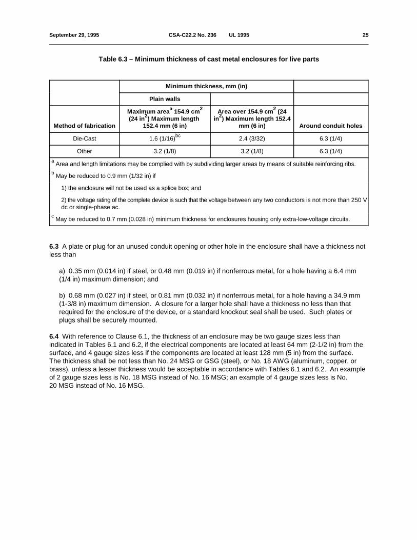
September 29, 1995 CSA-C22.2 No. 236 Ç UL 1995 25
Table 6.3 – Minimum thickness of cast metal enclosures for live parts
Minimum thickness, mm (in)
Plain walls
Method of fabrication 152.4 mm (6 in) mm (6 in) Around conduit holes
Maximum area 154.9 cm Area over 154.9 cm (24a 2
(24 in ) Maximum length in ) Maximum length 152.422
2
Die-Cast 1.6 (1/16) 2.4 (3/32) 6.3 (1/4)bc
Other 3.2 (1/8) 3.2 (1/8) 6.3 (1/4)
Area and length limitations may be complied with by subdividing larger areas by means of suitable reinforcing ribs.a
May be reduced to 0.9 mm (1/32 in) ifb
1) the enclosure will not be used as a splice box; and
2) the voltage rating of the complete device is such that the voltage between any two conductors is not more than 250 Vdc or single-phase ac.
May be reduced to 0.7 mm (0.028 in) minimum thickness for enclosures housing only extra-low-voltage circuits.c
6.3 A plate or plug for an unused conduit opening or other hole in the enclosure shall have a thickness notless than
a) 0.35 mm (0.014 in) if steel, or 0.48 mm (0.019 in) if nonferrous metal, for a hole having a 6.4 mm(1/4 in) maximum dimension; and
b) 0.68 mm (0.027 in) if steel, or 0.81 mm (0.032 in) if nonferrous metal, for a hole having a 34.9 mm(1-3/8 in) maximum dimension. A closure for a larger hole shall have a thickness no less than thatrequired for the enclosure of the device, or a standard knockout seal shall be used. Such plates orplugs shall be securely mounted.
6.4 With reference to Clause 6.1, the thickness of an enclosure may be two gauge sizes less thanindicated in Tables 6.1 and 6.2, if the electrical components are located at least 64 mm (2-1/2 in) from thesurface, and 4 gauge sizes less if the components are located at least 128 mm (5 in) from the surface. The thickness shall be not less than No. 24 MSG or GSG (steel), or No. 18 AWG (aluminum, copper, orbrass), unless a lesser thickness would be acceptable in accordance with Tables 6.1 and 6.2. An exampleof 2 gauge sizes less is No. 18 MSG instead of No. 16 MSG; an example of 4 gauge sizes less is No.20 MSG instead of No. 16 MSG.

26 CSA-C22.2 No. 236 Ç UL 1995 September 29, 1995
7 Openings in enclosures
Figure 7.1 – Probe (Other than Moving Parts)

September 29, 1995 CSA-C22.2 No. 236 Ç UL 1995 27
7.1 Uninsulated live parts excluding film-coated wire, of hazardous voltage circuits, shall be located,guarded, or enclosed so as to prevent unintended contact by persons reaching through openings in theenclosure, or by persons oiling motors, replacing air filters, adjusting controls, or performing other intendedservice and maintenance operations.
7.2 Openings in enclosures, including perforations, louvres, and openings protected by means ofscreening, expanded metal, or perforated covers, shall be of such size or shape as to prevent the passageof a probe, illustrated in Figure 7.1, from contacting uninsulated live parts. The configuration of the probeshall be changed (articulated) after insertion. See Clause 7.6 for film-coated wire.
7.3 During the examination of a unit or part thereof, in connection with the requirements in Clause 7.1,parts of the enclosure, such as covers, panels, and grilles are to be removed unless tools are required fortheir removal. A warning marking, such as specified in Clause 36.3(r) will be disregarded in establishingcompliance with these requirements.
7.4 In the case of downflow units provided with open coil elements that do not comply with Clause 5.7, themanufacturer's installation instructions shall specify that an L-shaped exhaust duct be used as a bottomclosure, without any outlets or registers located directly below open coil elements.
Exception: An acceptable barrier is considered to be provided by a finned coil construction at least tworows in depth and with at least 12 fins per 25.4 mm (1 in).
7.5 With reference to Clause 7.4, an air filter is not acceptable as a barrier.
7.6 A probe as illustrated in Figure 7.2 shall not touch film-coated wire when inserted through the opening.
Figure 7.2 – Probe (For Film-Coated Wire)

28 CSA-C22.2 No. 236 Ç UL 1995 September 29, 1995
8 Enclosures, doors, and covers
8.1 Doors and covers that give access to uninsulated live hazardous voltage parts shall be secured firmlyin place, and shall require the use of a tool or key to open them or shall be provided with an interlockingmechanism; except that components having covers that comply with their respective standards do notrequire additional enclosures.
8.2 An interlocking mechanism complies with the requirements of Clause 8.1 if it
a) secures the cover in the closed position when engaged; and
b) must be engaged before parts in a hazardous voltage circuit can be energized.
9 Accessibility of parts
9.1 Sufficient and reasonable accessibility shall be afforded to all parts that require normal servicing oradjustment (for example, controls, filters, oiling of bearings, adjustment of belts) when the equipment isinstalled as intended. Covers or access panels giving access to such parts that are required to be removedfor routine maintenance shall not expose uninsulated hazardous voltage live parts.
9.2 The assembly shall be arranged so that any overcurrent protective device that can be replaced or resetas required is accessible without removal of parts other than the service covers or panels.
9.3 Except as specified in Clause 9.4, the door or cover of an enclosure shall be hinged, sliding type,pivoted, or the equivalent, and not intended for removal, if it gives access to fuses.
Exception: If more than one door or cover has to be opened to provide access , only one of these need tocomply with this requirement.
9.4 A cover as specified in Clause 9.3 is not required if only fuses of the following types are enclosed:
a) fuses connected in extra-low-voltage circuits;
b) extractor type fuses that have their own enclosures;
c) control circuit fuses provided that the control circuit loads (other than fixed loads, such as pilot lamps)are housed in the same enclosure as the fuses; or
d) supplementary type fuses rated 2 A or less used in small, auxiliary resistance heater circuits having amaximum rating of 100 W.
9.5 The reset button or lever of manual resettable devices (for example, the operating handle of a circuitbreaker, the reset button of a motor protector, the reset button of a pressure switch, the adjusting screw orknob of an adjustable temperature or pressure control) may be accessible without the use of a tool,providing that the resetting of the device does not result in exposure to uninsulated live hazardous voltageparts or moving parts. Outdoor units are to meet the rain test requirements of Clauses 13.1, 13.3, andSection 58.
9.6 A cover as specified in Clause 9.3 shall not depend solely upon screws or other similar means to hold itclosed, but shall be provided with an automatic latch or the equivalent. A spring latch, a magnetic latch, adimple, or any other mechanical arrangement that will hold the door in place and would require some effort on the user's part to open is considered to be acceptable for holding the door

September 29, 1995 CSA-C22.2 No. 236 Ç UL 1995 29
closed. A cover interlocking mechanism, as described in Clause 8.2, and provided as the sole means forsecuring the cover or panel, is considered to comply.
10 Assembly
10.1 A unit for use with a duct system shall have provision for the intended connection of ducts, either in theform of duct flanges, openings without flanges, or locations marked for openings, providing that drilling orcutting into the cabinet, or the use of screws, will not damage electrical or refrigeration components andwiring. A distance of 152 mm (6 in) separating the opening from all components and wiring is considered toprevent damage due to drilling or cutting. Protection may be provided by equivalent means.
10.2 A unit with electric heaters with an inlet or outlet duct that penetrates the building structure supportingthe unit shall be provided with a mounting base of noncombustible material so designed that, after the unitis installed, there will be no open passages through the supporting structure that would permit flame or hotgases from a fire originating in the space below the supporting structure to travel to the space above thatstructure. If the unit is intended to be installed on a supporting structure of combustible material, the baseshall be so designed that the required clearance will be maintained between the supporting structure andthe unit, plenum, and attached duct. Spacers necessary to provide required clearances shall be attachedto the unit mounting base, and shall extend not less than 76 mm (3 in) below the upper surface of thesupporting structure, except that, in a unit designed for use only in a mobile home, the distance shall be notless than 19 mm (3/4 in).
10.3 Provision for the connection of water supply, drainage lines, and refrigerant lines shall be made asrequired.
10.4 The components of a condensing unit and compressor unit, as covered by these requirements(Clause 2.1), shall be factory-assembled to form a single structural assembly such as a base or frame orrefrigeration component.
Exceptions:
1) The motor overload protective devices and motor controllers may be packaged with a condensingunit or compressor unit, provided they are of a type that is suitable for remote mounting and field wiringto the unit.
2) Dryers, filters, and the like that are intended for installation in the field may be packaged with thecondensing unit or compressor unit, provided that they comply with the requirements in this Standard.
10.5 On liquid chillers employing centrifugal motor compressors, the motor-compressor controller andoverload protection are not required to be provided. Where not provided, the manufacturer shall provide aspecification for the controller and overload protection to be provided by the customer. The specificationshall include information as to the required controller rating, sequencing of start, overload protection tripcurrent, connections to the chiller control system, etc. If a current transformer is to be provided, as part ofthe controller, to provide a signal input circuit to the chiller control system, the specification is to include therequirements for the current transformer and its shunting resistor, if any. The controller and overloadprotection shall be provided for all other motors incorporated in the chiller assembly (see Clause 36.9).

30 CSA-C22.2 No. 236 Ç UL 1995 September 29, 1995
11 Mechanical protection
11.1 All moving parts (for example, fan blades, blower wheels, pulleys, and belts) that, if accidentallycontacted, could cause bodily injury, shall be guarded against accidental contact by an enclosure or screenrequiring tools for removal, or permanently attached.
11.2 Openings in external enclosures or guards provided for compliance with the requirements specified inClause 11.1, are acceptable if they prevent the probe, illustrated in Figure 11.1, applied at any angle withouta force, from making contact with moving parts.
Exceptions:
1) Equipment marked as required by Clause 36.3(s) need not be provided with guarding.
2) Openings of 25.4 mm (1 in) or larger shall be guarded such that the distance from an opening to themoving parts is in accordance with Table 11.1.

September 29, 1995 CSA-C22.2 No. 236 Ç UL 1995 31
Figure 11.1 – Probe (Moving Parts)

32 CSA-C22.2 No. 236 Ç UL 1995 September 29, 1995
Table 11.1 – Clearance from openings
Minor dimensions of opening moving partsMinimum distance from opening to
mm (in) mm (in)
More than 25.4 but not more More than (1) but not more than (1-1/2) 212.7 (8-3/8)than 38.1
More than 38.1 but not more More than (1-1/2) but not more than (2) 295.3 (11-5/8)than 50.8
More than 50.8 but not more More than (2) but not more than (3) 762.0 (30)than 76.2
11.3 An interlocking mechanism that operates to disconnect power to the drive motor when a cover orpanel is removed or opened to provide access to moving parts is considered to provide the protectionrequired by Clause 11.1.
11.4 Perforated sheet steel or expanded steel mesh used to cover openings shall give equivalentmechanical strength to that of a blank sheet of the thickness that will be required when determiningcompliance with Table 6.1.
11.5 If the starting or restarting of a motor driving a moving part is provided by an automatic cycling device,the moving part shall be guarded if the part is exposed when operating adjustments are made, or air filterschanged, or if the part is accessible without the use of tools.
12 Outdoor use equipment
12.1 Sheet steel cabinets and enclosures of units intended for outdoor use shall be protected againstcorrosion as specified in Table 12.1, or by other metallic or nonmetallic coatings that have been shown togive equivalent protection.
Nonferrous cabinets and enclosures may be employed without special corrosion protection. The thicknessof the material shall be judged on the basis of its strength and rigidity.

September 29, 1995 CSA-C22.2 No. 236 Ç UL 1995 33
Table 12.1 – Corrosion protection
Type of cabinet and enclosure by Clause: Clause:
1.35 mm (0.053 in) Less than 1.35 mm (0.053 in)uncoated/1.42 mm (0.056 in) uncoated and 1.42 mm (0.056
coated and greater as specified in) coated as specified by
Outer cabinets that protect motors, wiring, or 12.2 12.3enclosed current-carrying parts
Inside enclosures that protect current-carrying 12.2 12.3parts other than motors
Outer cabinets that are the sole enclosure of 12.3 12.3current-carrying parts
12.2 Where Table 12.1 references this Clause, a cabinet or enclosure intended for outdoor use shall beprovided with one of the following coatings:
a) Hot dipped mill galvanized sheet steel conforming with the coating designation G60 or A60 in Table 1of the Standard for Steel Sheet, Zinc-Coated (Galvanized) for Zinc-Iron Alloy-Coated (Galvannealed) bythe Hot-Dip Process, ASTM A653-94 or in Table 1 of the Standard for Steel Sheet, Zinc-Coated(Galvanized) for Zinc-Iron Alloy-Coated (Galvannealed) by the Hot-Dip Process (Metric), ASTMA653M-94, with not less than 40% of the zinc on any side, as determined by the minimum single spottest requirement in this ASTM designation. The weight of zinc coating may be determined by anyrecognized method; however, where results are in question, the weight of coating shall be established inaccordance with Tests for Weight of Coating on Zinc-Coated Iron or Steel Articles, ASTM A90-81.
b) A zinc coating, other than that provided on hot dipped mill galvanized sheet steel, uniformly appliedon each surface to an average thickness of not less than 0.01041 mm (0.00041 in), and to a minimumthickness of 0.00864 mm (0.00034 in).
c) Two coats of outdoor paint on both surfaces. The suitability of the paint shall be determined byconsideration of its composition.
12.3 Where Table 12.1 references this Clause, a cabinet or enclosure intended for outdoor use shall beprovided with one of the following coatings:
a) Hot dipped mill galvanized sheet steel having the coating designation G90 in Table 1 of ASTMdesignation A653-94 or A653M-94, with not less than 40% of the zinc on any side as determined by theminimum single spot test requirement in these ASTM designations. The weight of zinc coating may bedetermined by any recognized method; however, where results are in question, the weight of coatingshall be established in accordance with the test method of ASTM designation A90-81.
b) A zinc coating, other than that provided on hot dipped mill galvanized sheet steel, uniformly appliedon each surface to an average thickness of not less than 0.01549 mm (0.00061 in), and to a minimumthickness of 0.01372 mm (0.00054 in).
34 CSA-C22.2 No. 236 Ç UL 1995 September 29, 1995
c) A zinc coating complying with Item (a) or (b) of Clause 12.2, plus one coat of outdoor paint asspecified in Item (c) of Clause 12.2 on each surface.
12.4 Other finishes, including paints, special metallic finishes, and combinations of the two may beaccepted when comparisons with galvanized sheet steel (without annealing, wiping, or other surfacetreatment) that complies with Item (a) of Clause 12.2 or 12.3, as applicable, indicate they provide equivalentprotection.
12.5 Metals shall not be used in combinations such as to cause galvanic action that will adversely affectcabinets or enclosures.
13 Enclosures, outdoor use
13.1 The outer cabinet of the equipment intended for outdoor use shall be so constructed as to prevent thewetting of uninsulated live parts (hazardous voltage or extra-low-voltage safety circuits), and shall protectthe system against risk of shock due to exposure to rain (see Rain Test, Section 58). If of steel, it shall benot less than 0.78 mm (0.0307 in) thick, and shall be suitably protected against corrosion as required bySection 12. Enclosures made of other metal shall have mechanical strength and rigidity at least equivalentto that of steel, 0.78 mm (0.0307 in) thick.
13.2 An enclosure that is formed of metal which is thinner than specified in Clause 13.1, and whichcomplies with Tables 6.1 and 6.2, whichever applies, is acceptable if it is protected by an outer cabinet. Asheet steel cabinet or enclosures employing panels consisting of more than one sheet, each sheet thinnerthan specified in Clause 13.1, may be used if equivalent in all respects, including mechanical strength andcorrosion resistance, to a single sheet of steel of the thickness specified in Clause 13.1.
13.3 Service covers and access panels that are not secured by screws or other fasteners requiring the useof tools to remove them shall be left open or removed during the Rain Test described in Section 58.
13.4 An enclosure for electrical components shall have provision for drainage if the enclosure employsknockouts or unthreaded openings. The drainage holes shall be not less than 3.2 mm (1/8 in) in diameter,or drainage openings of at least equivalent size shall be included.
13.5 Units with polymeric cabinets shall comply with Section 5.9.
13.6 Gaskets required to seal enclosures of electrical components shall comply with the requirements ofSection 59, Accelerated aging tests–Gaskets.
14 Field wiring connections, outdoor use equipment
14.1 Conduit openings or knockouts shall be provided for all field wiring connections, and shall be at least22.2 mm (7/8 in) in diameter. Threaded openings shall be provided unless
a) the opening is wholly below the lowest uninsulated live hazardous voltage part within the enclosure;or
b) the opening prevents drainage into the enclosure along the outside surface of a field suppliedwireway; or

September 29, 1995 CSA-C22.2 No. 236 Ç UL 1995 35
c) the routing of the factory- or field-supplied wiring is necessarily such that a drip-loop is formed, whichphysically prevents any entering moisture from reaching uninsulated live parts.
14.2 Threads for the connection of conduit are tapped all the way through a hole in an enclosure wall, or ifan equivalent construction is employed, there shall be not less than three nor more than five threads in themetal. Construction of the device shall be such that a conduit bushing can be properly attached. If threadsfor the connection of conduit are not tapped all the way through a hole in an enclosure wall, conduit hub, orthe like, there shall be not less than 3-1/2 threads in the metal. There shall be a smooth, rounded inlet holefor the conductors which shall afford protection to the conductors equivalent to that provided by a standardconduit bushing and which shall have an internal diameter approximately the same as that of thecorresponding trade size of rigid conduit.
14.3 An enclosure threaded for support by rigid conduit shall provide at least five full threads for engagingwith the conduit.
15 Mechanical assembly
15.1 Parts used in the construction of the complete assembly shall have adequate strength, and shall beassembled and secured in position to ensure proper functioning under both normal and abnormalconditions that may be met in service. Refrigerant-containing parts shall have all joints made to preventleakage of refrigerant under the aforementioned conditions.
15.2 Self-contained units that are designed to be shipped in separable sections (eg, wall sleeve, coolingsection, heating section, control section, front panel) shall be marked in accordance with the requirementsof Clause 36.3, and the following shall be complied with:
a) each section shall be constructed and packaged so as to prevent damage to the parts duringshipment and assembly;
b) each section and the contents shall be identified as required by Clause 36.3(a) and (b); additionallythe unit shall be marked to identify each section;
c) electrical connections between the separable sections shall be capable of being made withoutadditional parts being required, such as wiring, connectors, receptacles, terminal blocks;
d) electrical bonding shall be maintained between sections after assembly;
e) all connections shall be properly marked for assembly;
f) guards required by Section 11 shall be secured to the appropriate section, and shall not be shippedas a separate item for field assembly;
g) safety controls shall be an integral part of the sections requiring them; and
h) each package shall contain that part of the installation instructions necessary to assemble it into theother sections.
15.3 The heating section referred to in Clause 15.2 may be a separable heater element assembly with allassociated controls necessary for the proper operation of the elements, without an integral casing orenclosure for the electrical components, provided that the assembly is designed for field installation withinthe unit enclosure.

36 CSA-C22.2 No. 236 Ç UL 1995 September 29, 1995
16 Auxiliary devices
16.1 A unit having provisions for the use of additional auxiliary devices intended to be attached in the fieldshall be constructed so that their use will not cause a risk of fire, electric shock, or injury.
16.2 The unit shall comply with the requirements of this Standard, both with and without the auxiliary deviceinstalled.
16.3 The installation of auxiliary devices by service personnel shall be by means of receptacles, plug-inconnectors, wiring terminals, insulated wire connectors, or by connection to existing wire terminals.
16.4 Any installation of an auxiliary device shall not require the cutting of wiring or the soldering ofconnections by the installer, and shall not require cutting, drilling, or welding in electrical enclosures and inother areas where such operations may damage electrical or refrigeration components and wiring.
16.5 Field rearrangement of components shall not be acceptable.
Exception: The rearrangement of components to provide field change of direction of air flow, is acceptableif factory provisions are made for such an option.
16.6 As part of the investigation, a trial installation of auxiliary devices may be made, to determine that itsinstallation is feasible, that the instructions are detailed and correct, and that its use does not cause a risk offire, electric shock, or injury.
16.7 A strain relief means shall be provided for the wiring in the auxiliary device, if there is any possibility oftransmitting stress to the terminal connections during installation.
16.8 All terminals and wiring intended to be field-connected shall be identified on the auxiliary device, theunit (if connections are made between the device and the unit), and the wiring diagram.
16.9 The mounting location of the auxiliary device shall be indicated on the unit. However, if the mountinglocation is predetermined by the function of the device and arrangement of the unit, and if instructions areprovided covering the installation and location for the device, the mounting location of the device need notbe indicated (for example, no indication is needed where an air heater is to be installed on the outlet ductflanges of the unit).
17 Connection to power supply
17.1 Equipment other than cord-connected (see Clause 1.2) shall have provision for the connection ofconduit (or conduits) of a size (see Table 17.1) suitable for the supply circuit conductors (see Table 17.2)needed to connect the unit in accordance with Tables 1 through 4 in the Canadian Electrical Code, Part I,CSA Standard C22.1, and Tables 310-16 and 310-17 in the National Electrical Code, ANSI/NFPA No.70-1993. Provisions may be made for field cutting the openings necessary for field wiring systemconnections, provided that their intended locations are indicated by one of the following methods:
a) use of pilot holes intended for use with a hole punch; or
b) an attached marking showing the exact centre of each opening; or

September 29, 1995 CSA-C22.2 No. 236 Ç UL 1995 37
c) an attached marking showing the area in which the openings can be located.
17.2 Field-provided openings for field wiring system connections shall be so located that the necessarycutting, drilling, or punching operation is not likely to damage components or wiring within the enclosure. Separation shall be maintained as specified in Clause 10.1.
17.3 A metal plate to which conduit is to be attached in the field shall be not less than 0.78 mm (0.0307 in)thick if uncoated steel, not less than 0.88 mm (0.0346 in) thick if galvanized steel, and not less than1.14 mm (0.045 in) thick if nonferrous metal.
17.4 A knockout shall be provided with a flat surrounding surface for seating of a conduit bushing, andshall be located so that installation of a bushing at any knockout likely to be used during installation will notresult in spacings between uninsulated live parts and the bushing of less than those required by Section32–Spacings.
17.5 The construction of the equipment at the point where the conduit of the supply is attached shall besuch that supply conductors can be installed in compliance with the requirements of Section 21–Separationof Circuits.
17.6 The space provided at terminals or leads intended for the connection of supply conductors, or otherconductors to be connected at the time of installation, shall be sufficient for acceptable installation (seeClause 17.7) including the accommodation of the necessary splices.
17.7 An acceptable installation shall
a) be possible using ordinary tools suitable for the installation; and
b) not require installed conductors to be forced into contact with uninsulated live parts, or withnoncurrent-carrying parts likely to be grounded.
A trial installation may be performed to determine compliance with these requirements.
17.8 Equipment which incorporates more than one independent internal circuit, and is designed forconnection to more than one source of electrical power supply shall have each internal circuit provided withmeans for connection to the supply, in accordance with Section 17.
17.9 Hazardous voltage circuit connections shall be made within acceptable enclosures or outlet boxes.
The location of an outlet box or compartment in which supply connections are made shall be such that theconnections will be readily accessible for inspection after the equipment is installed as intended.

38 CSA-C22.2 No. 236 Ç UL 1995 September 29, 1995
Table 17.1 – Knockout or hole sizes and dimensions of bushings
Trade size of conduit Knockout or hole diameter Overall diameter Height
Bushings dimensions
mm in mm in mm in mm in
21.3 1/2 22.2 7/8 25.4 1 9.5 3/8
26.7 3/4 27.8 1-3/32 31.4 1-15/64 10.7 27/64
33.4 1 34.5 1-23/64 40.5 1-19/32 13.1 33/64
42.3 1-1/4 43.7 1-23/32 49.2 1-15/16 14.3 9/16
48.3 1-1/2 50.0 1-31/32 56.0 2-13/64 15.1 19/32
60.3 2 62.7 2-15/32 68.7 2-45/64 15.9 5/8
73.0 2-1/2 76.2 3 81.8 3-7/32 19.1 3/4
88.9 3 92.1 3-5/8 98.4 3-7/8 20.6 13/16
101.6 3-1/2 104.8 4-1/8 112.7 4-7/16 23.8 15/16
114.0 4 117.5 4-5/8 126.2 4-31/32 25.4 1
127.0 4-1/2 130.2 5-1/8 140.9 5-35/64 27.0 1-1/16
141.3 5 142.9 5-5/8 158.0 6-7/32 30.2 1-3/16
168.3 6 171.5 6-3/4 183.4 7-7/32 31.8 1-1/4

September 29, 1995 CSA-C22.2 No. 236 Ç UL 1995 39
Table 17.2 – Trade size of conduita
Wire size 2 3 4 5 6
Number of wires
(mm ) AWG2
(2.1) 14 1/2 1/2 1/2 1/2 1/2
(3.3) 12 1/2 1/2 1/2 3/4 3/4
(5.3) 10 1/2 1/2 1/2 3/4 3/4
(8.4) 8 3/4 3/4 1 1 1-1/4
(13.3) 6 3/4 1 1 1-1/4 1-1/4
(21.2) 4 1 1 1-1/4 1-1/4 1-1/2
(26.7) 3 1 1-1/4 1-1/4 1-1/2 1-1/2
(33.6) 2 1 1-1/4 1-1/4 1-1/2 2
(42.4) 1 1-1/4 1-1/4 1-1/2 2 2
(53.5) 0 1-1/4 1-1/2 2 2 2-1/2
(67.4) 2/0 1-1/2 1-1/2 2 2 2-1/2
(85.0) 3/0 1-1/2 2 2 2-1/2 2-1/2
(107.2) 4/0 2 2 2-1/2 2-1/2 3
kcmil
(127) 250 2 2-1/2 2-1/2 3 3
(152) 300 2 2-1/2 3 3 3-1/2
(177) 350 2-1/2 2-1/2 3 3-1/2 3-1/2
(203) 400 2-1/2 3 3 3-1/2 4
(253) 500 3 3 3-1/2 4 4
This Table is based on the assumption that all conductors will be of the same size and there will be no more than sixa
conductors in the conduit. If more than six conductors will be involved or if all of them are not of the same size, the internalcross-sectional area of the smallest conduit that may be used is determined by multiplying by 2.5 the total cross-sectionalarea of the wires, based on the cross-sectional area of type THW specified in the National Electrical Code or type TW75,specified in the Canadian Electrical Code, Part I, CSA Standard C22.1.

40 CSA-C22.2 No. 236 Ç UL 1995 July 31, 1998
18 Thermal insulation and air filters
18.1 Thermal insulation such as mineral wool, which may contain conductive impurities, shall not contactuninsulated live parts.
18.2 Materials in a compartment handling conditioned air for circulation through a duct system shall havea
a flame spread rating of not more than 25, and a smoke developed rating of not more than 50, when testedas specified in Surface Burning Characteristics of Building Materials and Assemblies, CAN/ULC-S102, andThe requirements for Standard Method of Tests for Surface Burning Characteristics of Building Materials,UL 723. This requirement does not apply to the following:
a) air filters, drive belts, wire insulation, paint applied for corrosion protection, or tubing of materialequivalent to one of the types of wire insulation permitted by this Standard;
b) gaskets forming air or water seals between metal parts;
c) miscellaneous small parts such as refrigerant line bushings or insulating bushings, resilient orvibration mounts, wire ties, clamps, labels, or drain line fittings having a total exposed surface area notexceeding 161.29 cm (25 in );2 2
d) an adhesive that, when tested in combination with the specific insulating material, complies with therequirement;
e) moulded or formed components (not liners) of polymeric materials in such quantities that their totalexposed surface area within the compartment does not exceed 0.93 m (10 ft ); or2 2
f) materials in a compartment handling air for circulation through a duct supplying only one room.
See Table 38.3 when material is not in a compartment handling conditioned air for circulation through aa
duct system.
18.3 Polymeric materials exempted by Item (e) of Clause 18.2 shall have a flame spread rating of not morethan 25, or shall comply with the requirements of the vertical burning test for classifying materials 94-5 V inaccordance with the Standard Tests for Flammability of Plastic Materials in Devices and Appliances, UL 94,and Test 5 V (500 W) of Evaluation of Properties of Polymeric Materials, CAN/CSA-C22.2 No. 0.17 with aflammability rating of 5 VA.
18.4 Thermal or acoustic insulating material shall be securely positioned if loosening may reduce or blockair flow so as to cause temperatures or pressures in excess of those acceptable in the temperature andpressure tests, or if loosening will result in reduction of electrical spacings below the required values, shortcircuiting, or grounding. Leading edges of insulation shall be protected against damage from the effects ofmoving air.

July 31, 1998 CSA-C22.2 No. 236 Ç UL 1995 40A
18.5 A mechanical fastener for each 0.1 m (1 ft ) of exposed surface is considered to securely position2 2
insulating liners to meet the requirement of Clause 18.4. Mechanical fasteners may be bolts, metalclamps, wire rods, or the equivalent. Butting edges of insulation against bulkheads normally provideprotection for leading edges against damage from the effects of moving air. Rigid or semi-rigid sheets ofinsulating material may not require fastening to the extent needed for less rigid material, nor is protection ofleading edges, for such material, required.
18.6 An adhesive provided to secure insulating material, to comply with Clause 18.4, shall retain itsadhesive qualities at any temperature attained by the adhesive when the unit is tested under therequirements of this Standard, and at –18EC (0EF) for indoor use equipment, and at –29EC (–20EF) foroutdoor use equipment.

40B CSA-C22.2 No. 236 Ç UL 1995 July 31, 1998
No Text on This Page

September 29, 1995 CSA-C22.2 No. 236 Ç UL 1995 41
18.7 Liquid adhesive coatings, where used with air filters, shall have a flash point of 176.7EC (350EF) orhigher.
18.8 As a protection against overheating, there shall be a minimum clearance of 50 mm (2 in) between themotor of an air circulating blower and the face of an air filter exposed to the motor, with the air filter in theintended position above the motor, and with the motor adjusted to its minimum clearance from the filterface. Alternatively, the equivalent protection may be afforded by suitable baffles, or by a motor having anenclosed housing.
18.9 Adequate support shall be provided to maintain the air filters in their intended position.
19 Terminal parts and leads for field wiring connections
General
19.1 A unit shall have provision for connection of one or more of the power supply wiring systems that, inaccordance with the Canadian Electrical Code, Part I, CSA Standard C22.1, and the National ElectricalCode, ANSI/NFPA No. 70-1993, is applicable to the unit.
19.2 Where leads are provided for making connection to the power supply, they shall be not less than No.18 AWG. These leads shall be provided with means for strain relief if stress on the leads may betransmitted to terminals, splices, or internal wiring that may cause the leads to separate from theirterminations, or subject them to damage by sharp edges.
19.3 Field wiring terminals shall have means other than friction to prevent them from turning, which mightresult in unacceptable electrical spacings.
19.4 Line terminals of an approved control or fuseholder may be used as field wiring terminals providedthey comply with the requirements of Clauses 19.13 and 19.14.
19.5 The location of an outlet box or compartment in which field wiring connections are to be made shallallow these connections to be inspected after the unit is installed as intended.
19.6 The connections shall be accessible without removal of parts other than service covers or panels andthe cover of the outlet box or compartment in which the connections are made.
19.7 The free end of any lead that may not be used in every installation shall be insulated, if that end couldreduce spacings below the minimum acceptable values.
19.8 Equipment (including auxiliary devices) that is not part of the unit, but that is supplied for fieldinstallation, shall have provision for field wiring connections as specified above, except that specialconnectors may be used if both mating parts are provided and factory-attached to the equipment.
19.9 The surface of an insulated lead intended solely for the connection of an equipment groundingconductor shall be finished a continuous green, or a green with one or more yellow stripes. No other leadsvisible to the installer, other than grounding conductors, shall be so identified.
Exceptions:
1) This requirement does not apply to leads or wiring that are intended to be field-connected toextra-low-voltage circuits, and that are separated or segregated by barriers from field wiring connectionsin circuits exceeding 30 V.

42 CSA-C22.2 No. 236 Ç UL 1995 July 31, 1998
2) This requirement does not apply to internal wiring that is not visible in a field wiring compartment.
19.10 Control equipment, including an auxiliary device that is not part of the product but is supplied with theproduct for field installation, shall have provision for field wiring connections as required by Section 17,Connection to Power Supply, except that special connectors may be used if both mating parts are provided,and factory-attached to the product or the auxiliary device.
Hazardous Voltage Circuits
19.11 Units other than cord-connected (see Clause 1.2) shall be equipped with wiring terminals or leadsnot less than 152 mm (6 in.) long for connection of field wiring conductors. If a single conductor larger than500 kcmil would be required, the unit shall have provision for the connection of conductors in parallel.
If a product is marked (see Clause 37.9) to indicate that it is acceptable for use with either copper, copperclad aluminum, or aluminum power supply conductors, a field wiring terminal shall comply with therequirement in Clause 19.1 for a wire of each metal.
19.12 A field wiring terminal or lead for the connection of a grounded conductor in accordance with NECand the identified conductor in accordance with CEC Part I shall be finished a white or natural grey. Noother leads other than grounded conductors shall be so identified.
Exceptions:
1) This requirement does not apply to internal wiring that is not visible in a field wiring compartment; or
2) This requirement does not apply to terminals that are identified by a marking on the unit "WHITE" orequivalent.
19.13 If a wire binding screw is employed at a field wiring terminal intended for the connection of supplycircuit conductors, it shall be not smaller than No. 8 if the supply circuit conductors are No. 14 AWG; andnot smaller than No. 10 if the supply circuit conductors are No. 12 or No. 10.
19.14 If conductors of the field wiring to be connected will be larger than No. 10 AWG, a field wiringterminal part shall either include a connector suitable for clamping the required conductors, or shall besuitable for use with such a connector or an appropriate soldering lug.
19.15 In determining the size of the power supply terminals or conductors required, unless the equipmentis otherwise marked it is assumed that supply conductors rated 75EC (167EF) will be used.
19.16 Terminal parts for factory-installed conductors that are larger than No. 8 AWG shall includesolderless connectors or soldering lugs, unless the suitability of the combination of terminal and conductortermination has been investigated.

July 31, 1998 CSA-C22.2 No. 236 Ç UL 1995 42A
19.17 For equipment intended for connection with two or more supply conductors in parallel per terminal,the terminals shall be of a size suitable for securing connectors that are appropriate for the termination ofthe conductors.
19.18 A field wiring terminal or lead shall be provided for connection of an equipment grounding conductor.
Exception: The equipment grounding terminal or lead may be omitted if all the following conditions aresatisfied:
1) the rating of the product is such that the power supply conductors are likely to be larger thanNo. 2 AWG;

42B CSA-C22.2 No. 236 Ç UL 1995 July 31, 1998
No Text on This Page

July 31, 1998 CSA-C22.2 No. 236 Ç UL 1995 43
2) the construction is such that an acceptable terminal can be installed in the field, for example, theterminal can be secured as intended without a drilling or cutting operation upon installation, andsufficient space for the equipment grounding conductor is provided; and
3) the product is marked: "If this product is supplied by a wiring system that, in accordance withCanadian Electrical Code, Part I, CSA Standard C22.1, and the National Electrical Code, ANSI/NFPANo. 70-1993, requires the installation of an equipment grounding conductor or conductors, a terminal orterminals for connection thereof must be installed", or with an equivalent statement. This marking shallbe located in the wiring compartment where the power supply conductors will be connected, and shallgive adequate pertinent information, such as where the terminal or terminals should be mounted, howthey should be mounted, etc.
19.19 Each equipment grounding terminal or lead shall be located in the field wiring compartment, andshall be identified as specified in Clause 19.9 or 19.23, as applicable.
19.20 If more than one circuit is intended to be connected to the unit, the terminals or leads provided forfield connection of the equipment grounding conductor shall comply with the applicable requirements forconnection of a separate grounding conductor for each circuit.
19.21 If provision is made for connection of two or more power supply conductors in parallel at eachterminal, as mentioned in Clause 19.11, provision shall be made for connection of an equal number ofequipment grounding conductors.
19.22 The size of each grounding conductor shall comply with the applicable requirements for connectionof an equipment grounding conductor as specified in Table 16 of the Canadian Electrical Code, Part I, CSAStandard C22.1, and Table 250-95 of the National Electrical Code, ANSI/NFPA No. 70-1993, except thatsuch a conductor need be no larger than one of the power supply conductors.
19.23 A wire binding screw intended for the connection of an equipment grounding conductor shall have agreen coloured head that is hexagonal shaped, slotted, or both. A pressure wire connector intended forconnection of this conductor shall be identified by being marked "G", "GR", or the equivalent, or by beingrepresented on a wiring diagram provided on the unit. The wire binding screw or pressure wire connectorshall be located so that it does not need to be removed during servicing of the equipment. Upturned lugs orthe equivalent shall be provided at a wire binding screw to retain the conductor. If a pressure connector isused adjacent to the connectors intended for the supply conductors involving the neutral of a groundedsupply, a marking shall also be provided indicating "equipment ground" or the connector shall be identifiedby a green colour.
19.24 The wiring compartment intended for connection of the power supply conduit or raceway shall beattached to the unit so that it is prevented from turning.
This does not preclude the application of an outlet box, control box, or equivalent enclosure (to which thepower supply connections are to be made) connected to the unit by suitable factory wiring enclosed within alength of flexible metal conduit, providing that suitable conduit fittings are applied. Unless the conduit isterminated in an outlet box no larger than 102 × 102 × 51 mm (4 × 4 × 2 in) for the splice connections,locknuts on the fittings are not considered to be an acceptable means of preventing loosening of theconduit fittings. A grounding conductor of the size specified in Clause 19.22 shall be included.
19.25 A field wiring lead shall be no more than two standard wire sizes smaller than the conductor to whichit will be connected except as indicated in Clause 19.26.

44 CSA-C22.2 No. 236 Ç UL 1995 July 31, 1998
19.26 The leads specified in Clause 19.25 may be more than two wire sizes smaller than the field providedconductors to which they will be connected (but not smaller than No. 18 AWG), when more than onefactory-provided lead is intended for connection to the same field-provided lead wire, providing that
a) the wire connector for the splice connection to the field-provided wire is provided as part of the unit,and the wire connector is acceptable for the combination of wires that will be spliced;
b) a marking is included indicating that the provided wire connector is to be used for the field wiringsplice connection; and
c) the factory-provided leads are grouped in a manner to prevent stress on an individual lead.
19.27 A lead provided for connection to an external circuit shall not be connected to a wire binding screw orpressure terminal connector located in the same compartment as the splice, unless
a) the screw or connector is rendered unusable for field wiring connections; or
b) the lead is insulated at the unconnected end, and its intended use is clearly indicated (for example,on the applied wiring diagram).
19.28 A terminal plate for a wire binding screw shall be of metal not less than 0.76 mm (0.030 in) thick fora conductor sized No. 14 AWG or smaller, and not less than 1.27 mm (0.050 in) thick for a conductorlarger than No. 14 AWG. In either case there shall be not less than two full threads engaging. (Theterminal plate may be extruded at the tapped hole to provide the two full threads.)
19.29 On cord-connected equipment, the power supply cord shall be Type S, SJ, SJO, SO, ST, SJT, orequivalent. The length of the cord shall be no less than 0.61 m (2 ft) and no more than 1.83 m (6 ft)measured to the face of the attachment plug from the unit. The supply cord shall have an ampacity at leastequal to the total input in amperes measured during the normal temperature test (see Section 64). Thesupply cord ampacity shall be determined from Table 12 in the Canadian Electrical Code, Part I, CSAStandard C22.1, and Table 400-5 in the National Electrical Code, ANSI/NFPA No. 70-1993.
19.30 On cord-connected equipment, the power supply cord shall terminate in a grounding typeattachment plug that shall have a rating not less than 125% of the marked input in amperes.
19.31 On liquid chillers employing centrifugal motor-compressors, soldering lugs or pressure terminalconnectors are not required to be provided by the manufacturer for connection of the field wiring to themotor-compressor power-supply terminals. Threaded studs of adequate size and length shall be provided. Nuts for the studs shall be provided to adequately secure at least one terminal connector to each threadedstud.

July 31, 1998 CSA-C22.2 No. 236 Ç UL 1995 44A
Extra-Low-Voltage Circuits
19.32 Leads for making connection to the extra-low-voltage supply circuit shall be of adequate length.
19.33 Openings for the entry of conductors of an extra-low-voltage circuit shall be provided with insulatingbushings. The bushing shall be either mounted in place in the opening, or shall be packed within theenclosure for mounting when the unit is installed.
Exception: An insulating bushing need not be provided if
1) a wiring assembly for Class 2 control is furnished with the equipment;
2) the edges of the opening will not abrade the insulation on the wiring assembly; and

44B CSA-C22.2 No. 236 Ç UL 1995 July 31, 1998
No Text on This Page

July 31, 1998 CSA-C22.2 No. 236 Ç UL 1995 45
3) the insulation between any conductor of the wiring assembly and edges of the opening is at least1.2 mm (3/64 in) thick.
20 Internal wiring
20.1 This section shall apply to both hazardous voltage circuits and extra-low-voltage safety circuits, unlessstated otherwise. Extra-low-voltage nonsafety circuit wiring requirements are not specified.
20.2 Wireways shall be smooth and entirely free from sharp edges and burrs.
20.3 Only conductors having oil-resistant insulation shall be used where the conductors may be exposed tooil, grease, oily vapour, or other substances having a deleterious effect.
20.3A Wiring exposed periodically to moisture shall have moisture-resistant properties.
20.4 Wiring shall have insulation rated for the potential involved and the temperatures to which it may besubjected. Temperatures are to be judged on the basis of the temperatures measured during theapplicable temperature tests specified in Clause 38.1.
Exception: If it can be determined that the wiring will not be exposed to heat from radiating sources orheated components, and if the ampacity of the conductors is in accordance with Table 20.1 andClause 20.5, the temperature tests on the wiring may be waived.
Table 20.1 – Wiring material ampacitiesa
Wire size
mm AWG Ampacity2
0.41 22 4
0.66 20 7
0.82 18 10
1.3 16 13
2.1 14 18
3.3 12 25
5.3 10 30
8.4 8 40
13.3 6 55
21.2 4 70
33.6 2 95
42.4 1 110
The ampacities shown apply to appliance wiring materials with insulation rated not less than 90EC (194EF).a
For types of wires other than appliance wiring materials, the ampacity shall be determined from Tables 1 through 4 andTable 12 in the Canadian Electrical Code, Part I, CSA Standard C22.1 and Tables 310-16 and 310-17 in the NationalElectrical Code, ANSI/NFPA No. 70-1993 , for the type of wire employed. The correction factors of the referenced tablesneed not be applied.

46 CSA-C22.2 No. 236 Ç UL 1995 September 29, 1995
20.5 With reference to the exception in Clause 20.4, hazardous voltage circuit conductors supplying onemotor shall have an ampacity not less than 125% of the motor full load current rating. Conductorssupplying more than one motor shall have an ampacity not less than 125% of the full load current rating ofthe largest motor plus the full load current rating of any other motors supplied. Conductors supplying amotor load and other loads shall have an ampacity not less than 125% of the motor full load current ratingplus the marked current ratings or measured inputs of the additional loads supplied.
20.6 Conductors used in hazardous voltage circuits and extra-low-voltage safety circuits shall be selectedfrom Table 20.2 in accordance with the circuit requirements for conductor size, voltage, and temperaturerating.
Table 20.2 – Typical wiring materials
Group Type of wire, cord, or cable mm No. AWG mm ina,bWire size thickness
Insulation
2
A 33.6 2 1.6 4/64
Thermoplastic or thermoset appliance wiring material,with insulation thicknesses shown at the rightcorresponding to wire sizes indicated; or Type TW; orType AC, ACT, FFH-2, TF, TFF, TFN, TFFN, SF-2,d
SFF-2, RH, RHH, RHW, THW, XHH, XHHW, MTW,THHN, THW-MTW, THWN, PF, PGF, PFF, PGFF; orType GTF, TW75, TEW, TR-32, R90, RW90, T90,c
SEW-1, SEW-2
5.3 to 0.41 10 to 22 0.8 2/648.4 8 1.2 3/6413.3 6 1.6 4/6421.2 4 1.6 4/6426.7 3 1.6 4/64
42.4 1 2.0 5/6454.0 1/0 2.0 5/6467.0 2/0 2.0 5/6485.0 3/0 2/0 5/64
107.2 4/0 2.0 5/64
B 5.3 10 2.0 5/64
Appliance wiring material having thermoplastic or 0.82 18 1.6 4/64thermoset insulation, with insulation thicknesses shownat right corresponding to the wire sizes indicated; orType S, SJO, SJOO, SJT, SJTO, SJTOO, SO, SOO,SPT-3,ST,STO,STOO; or Type SE,SJE, or Typed c
NMD90,NMWU
1.3 16 1.6 4/642.1 14 2.0 5/643.3 12 2.0 5/64
8.4 8 2.4 6/6413.3 6 3.2 8/6421.2 4 3.6 9/6433.6 2 4.0 10/64
C Appliance wiring material with cross linked syntheticpolymer insulation; or Type S, SJ; or Type SP-3d Same as for Group B
The designated cord or cable, or types of wire other than appliance wiring material, may be used without regard to thea
values specified in the Table. Type CL wire may be used within a separate metal enclosure as leads of components.b
Wire types included only in the Canadian Electrical Code, Part I, CSA Standard C22.1.c
Wire types included only in the National Electrical Code, ANSI/NFPA No. 70-1993.d
20.7 Wiring shall be enclosed in metal clad cable, conduit, electrical metallic tubing, or metal raceways,control boxes, or the equivalent. Appropriate fittings shall be used. Wiring of the types referenced inGroups B or C of Table 20.2 may be employed in lieu of enclosed wiring, provided the requirements ofClause 20.8 are met.

July 31, 1998 CSA-C22.2 No. 236 Ç UL 1995 47
Exception: Wiring of the types in Group A of Table 20.2 may be employed if secured and supported toprevent damage and the requirements of Clause 20.8 are met.
20.8 Cords or appliance wiring material, used in the cabinet of equipment, shall be suitably enclosed so asto prevent damage to the wiring, ignition of combustible material, or emission of flame or molten metalthrough openings in the cabinet.
Such wiring is considered to be suitably enclosed when the cabinet or compartment enclosing the wiringhas
a) no openings in the bottom, unless a U-shaped channel or trough is located beneath the wiring, andthe wires do not project through the plane of the top of the channel or trough. A bottom closure isconsidered to be provided:
1) if the bottom opening is always intended to be connected to a supply or return indoor air duct; andthe unit includes space heating means (electric heater, hot water, or steam heating coil); or
2) if the unit is intended only for nonresidential applications and is so marked, except those openingsintended only for conduit or piping; or
3) if the bottom opening is provided with a finned coil construction at least two rows in depth and withat least 12 fins per 25.4 mm (1 in); or
4) if the bottom opening complies with Figure 23.1 and Clause 23.4; or
5) the bottom opening complies with the requirements of the tests specified in Appendix B;
b) no louvre or openings, other than duct openings, that will permit the probe (Figure 7.1), when appliedin a straight line, to contact wiring; and
c) no combustible material other than electrical insulation within the enclosure. Air filter may beemployed within the enclosure.
Exception: The separation specified in Item (b) does not apply to wiring located above openings in thebottom enclosure of a unit for outdoor installation, provided that such openings comply with therequirements of Clause 20.9.
20.9 On a unit for outdoor installation, the bottom surface of the enclosure may have openings, providedthat all of the following conditions are met (applies only to hazardous voltage circuits):
a) openings are less than 12.7 mm (1/2 in);
b) such openings are not located within 152 mm (6 in) of each other; and
c) the total area of such openings does not exceed 1% of the area of the enclosure bottom surface,less any area below a component such as a finned tube coil or hermetic motor compressor that ismounted directly on that surface.

48 CSA-C22.2 No. 236 Ç UL 1995 July 31, 1998
20.10 Thermoplastic-insulated hazardous voltage wiring materials that are referenced in Group A ofTable 20.2, and have an insulation thickness of 0.8 mm (2/64 in) for sizes 16 and 18 AWG, and 1.2 mm(3/64 in) for sizes Nos. 14, 12, 10, and 8 AWG, are considered to be equivalent to the wiring materialsreferenced in Group B when the conductors are covered with thermoplastic insulating tubing that has a wallthickness of 0.8 mm (2/64 in) and is of a type rated for the purpose from the standpoint of electrical,mechanical, and flammability properties. For sizes 6, 4, and 2 AWG, thermoplastic wiring materials that arereferenced in Group A of Table 20.2 and enclosed in thermoplastic tubing as described in this requirementare considered to be equivalent to the wiring materials specified in Group B when the total wall thickness (ofthe conductor insulation plus tubing) is not less than the value specified for Group B.
20.11 Wiring shall be protected against damage, shall be supported and routed to prevent damage due tocontact with sharp edges, such as fins on refrigeration coils, moving parts, or parts that may attain atemperature in excess of that for which the wiring insulation is rated, and shall not be immersed in waterunless rated for use in wet locations. Self-draining raceways that do not retain water are not considered torequire wiring for use in wet locations.
20.12 Splices in wiring shall be located, enclosed, and supported so that they are not subject to damage,flexing, motion, or vibration. A splice is considered to be acceptably enclosed when installed in a junctionbox, control box, or other enclosed compartment in which the wiring materials, as specified in Group A ofTable 20.2, may be employed. A splice in an enclosed machinery compartment shall be secured to a fixedmember in the compartment so that it is not subject to movement or damage during servicing. A splice orunused leads shall be provided with insulation equivalent in thickness, voltage and temperature rating tothat of the wires involved.
20.13 Stranded conductors at terminals shall be prevented from contacting other uninsulated live parts,which may not always be of the same polarity as the wire, and from contacting dead metal parts. Theshanks of terminal connectors shall be protected by insulating tubing, or equivalent, if the spacingsspecified in Section 32 may be reduced by loosening the clamping means.
20.14 A hole in a wall or partition through which insulated wires or cords pass and on which they may bearshall be provided with a smooth, rounded bushing or shall have a smooth, rounded surface upon which thewires or cords may bear. The bushings, where required, shall be of ceramic, phenolic, cold-mouldedcomposition, fibre, or other like material. Thermoplastic material shall not be clamped so as to causecold-flow of the material that can result in a risk of fire or electric shock.
20.15 Except as indicated in Clause 20.16, conductors of hazardous voltage motor circuits having two ormore thermal or overcurrent protected motors, or such (one or more) motors in combination with an electricresistance heater wired for connection to one power supply line, shall withstand short circuiting when testedin accordance with the short circuit test, described in Section 55. None of the conductors or leadterminations shall be damaged as a result of the short circuit test.

July 31, 1998 CSA-C22.2 No. 236 Ç UL 1995 48A
20.16 With reference to Clause 20.15, conductors that comply with at least one of the following areacceptable without test:
a) The conductors have an ampacity as determined from Table 20.1 for the type of wire or cordemployed of not less than 1/3 the ampacity of the supply conductors.
b) The conductors are 18 AWG or larger, and not more than 1.2 m (4 ft) in length, and the circuit will beprotected by an overcurrent protective device that is rated 60 A or less as specified on the unitnameplate or provided as part of the unit, and is acceptable for branch circuit protection.
c) The conductor is connected between two fixed impedances that reduce the risk of a high fault currentwithin the conductor (for example, a conductor extending between a motor running capacitor and thestart winding of a permanent split capacitor motor).
d) The conductor is a jumper lead between controls and is not longer than 76 mm (3 in) unless theconductor is located in a control panel.

48B CSA-C22.2 No. 236 Ç UL 1995 July 31, 1998
No Text on This Page

July 31, 1998 CSA-C22.2 No. 236 Ç UL 1995 49
21 Separation of circuits
21.1 Unless having insulation suitable for the highest voltage involved, insulated conductors of differentcircuits (internal wiring, including wires in a junction box or compartment) shall be separated by barriers, orshall be segregated, and shall, in any case, be separated or segregated from uninsulated live partsconnected to circuits of different voltages. Segregation of insulated conductors may be accomplished byclamping, routing, or equivalent means that ensures permanent separation from insulated or uninsulatedlive parts of a different circuit.
21.2 There shall be provision for segregating or separating by barriers, field-installed conductors of anycircuit from field-installed and factory-installed conductors connected to any other circuit, unless theconductors of both circuits are or will be insulated for the maximum voltage of either circuit.
21.3 Within a compartment that is not a control enclosure junction box or its equivalent, field-installedextra-low-voltage circuit conductors may be segregated from factory-installed conductors of differentcircuits by locating field wiring openings, routing factory wiring, and locating electrical components, so thatthe factory conductors are maintained at least 127 mm (5 in) from a line representing intended routing ofthe extra-low-voltage conductors. The line is to allow for droop, and is to connect the opening provided forentrance of the extra-low-voltage conductors to the terminals or leads to which the conductors areattached.
21.4 There shall be provision for segregating or separating by barriers field-installed conductors of ahazardous voltage circuit from
a) uninsulated live parts connected to a different circuit, other than wiring terminals; and
b) any uninsulated live parts of electrical components such as a pressure-limiting device, motoroverload protective device, or other protective device where short circuiting or grounding may result inunsafe operation of the equipment; except at wiring terminals.
21.5 There shall be provision for segregating or separating by barriers, field-installed conductors of anextra-low-voltage circuit from
a) uninsulated live hazardous voltage circuits; and
b) wiring terminals and any other uninsulated live parts of hazardous voltage electrical componentssuch as a pressure-limiting device, motor overload protective device, or other protective device whereshort circuiting or grounding may result in unsafe operation of the unit.
21.6 If a barrier is used to provide separation between the wiring of different circuits, it shall be of metal orof suitable insulating material of adequate mechanical strength, and reliably held in place.
21.7 A metal barrier shall be at least 0.66 mm (0.026 in) thick if of uncoated steel, 0.74 mm (0.029 in) thickif of galvanized steel, and 0.91 mm (0.036 in) thick if of nonferrous metal. A barrier of insulating materialsshall be not less than 0.71 mm (0.028 in) thick, and shall be of greater thickness if its deformation may beso readily accomplished as to defeat its purpose.
21.8 If the barrier is removable or has openings for the passage of conductors, it is acceptable providedthat instructions for the use of the barrier are a permanent part of the device. In lieu of a barrier, completeinstructions may be provided that, when used in conjunction with the wiring diagram, will provide for theseparation of the circuits of different voltages.

50 CSA-C22.2 No. 236 Ç UL 1995 July 31, 1998
21.9 Field-installed conductors may be segregated from other field-installed conductors and fromuninsulated live parts connected to other circuits, by arranging the location of the openings in the enclosurefor the various conductors, with respect to the terminals or other uninsulated live parts, so that conductorsor parts of different circuits will not intermingle.
21.10 The output of a transformer device supplying an extra-low-voltage circuit shall not be interconnectedwith the output of another such transformer device provided as a part of the equipment, unless the voltageand current measurements at the output terminals of the interconnected devices are extra-low-voltage.
21.11 Two or more transformer devices supplying extra-low-voltage circuits, and not more than 100 VA,and provided as a part of the equipment, shall be treated as separate circuits. If more than one such circuitis intended to be field-wired, the several circuits shall be segregated or separated by barriers as specified inClause 21.2, and the transformer output of each circuit shall be marked to warn that the separation shall bemaintained.
21.12 On liquid chillers employing centrifugal motor compressors, a signal input circuit derived from acurrent transformer sensing the motor-compressor current and located in the (remote) motor-compressorcontroller shall be a Canadian Electrical Code, Part I, CSA Standard C22.1, and National Electrical Code,ANSI/NFPA No. 70-1993, Class 1 circuit. (See Clause 26.16.)
22 Electrical insulation
22.1 Material for the mounting of uninsulated hazardous voltage parts shall be heat-resistant, absorptionresistant insulating material that is suitable for its particular application, and that will withstand the mostsevere conditions likely to be encountered in service.
Such materials include porcelain, phenolic composition, cold-moulded composition, or a material havingequivalent electrical and physical properties.
22.2 The acceptability of insulating materials shall include consideration of the following:
a) mechanical strength;
b) dielectric strength;
c) insulation resistance;
d) heat- and moisture-resistant properties;
e) the degree of enclosure or protection; and
f) other factors that might have a bearing on the risk of fire or electric shock under conditions ofintended use.
23 Motors
Motor Enclosures
23.1 The type of motor enclosure shall be suitable for the particular location in which the motor is to beused, unless adequate supplementary means of protection for the motor is provided.

July 31, 1998 CSA-C22.2 No. 236 Ç UL 1995 51
23.2 Openings in motors shall be located so that there is a noncombustible surface immediately belowthem.
23.3 In order to comply with the requirement of Clause 23.2, a barrier of noncombustible material shall beprovided under an open type motor unless one of the alternatives described in Items (a) to (c) is used:
a) the structural parts of the motor or unit, such as the bottom closure, provide protection equivalent tothat provided by such a barrier;
b) the overload protective device provided with the motor allows no burning insulation or moltenmaterial to fall to the surface that supports the unit while the motor is energized under each of thefollowing applicable fault conditions: open main winding; open starting winding; starting switchshort-circuited; or capacitor shorted (permanent split capacitor type); or
c) the motor incorporates a motor thermal protector (a protective device that is sensitive to temperatureand current) that will prevent the temperature of the motor windings from exceeding 125EC (257EF)while the motor is operated at the maximum load that will not cause the protector to cycle; and 150EC(302EF) while the motor is locked.
23.4 The barrier necessary for compliance with Clause 23.3 shall be horizontal and shall have an areaextending beneath the motor encompassing the openings in the motor housing and extending at least 5Ebeyond their area. Openings for drainage and ventilation may be included in the barrier, providing that theopenings do not permit molten metal, burning insulation, etc, to fall onto combustible materials. See Figure23.1.

52 CSA-C22.2 No. 236 Ç UL 1995 July 31, 1998
Figure 23.1 – Location and extent of barrier
A – Regions to be shielded by barrier. This will consist of the entire component if it is not otherwise shielded and will consist of theunshielded portion of a component that is partially shielded by the component enclosure or equivalent.
B – Projection of outline of component on horizontal plane.
C – Inclined line that traces out minimum area of barrier. This line is always (1) tangent to the component, (2) 5 degrees from the vertical,and (3) so oriented that the area traced out on a horizontal plane is maximum.
D – Location (horizontal) and minimum area for barrier. The area is that included inside the line of intersection traced by the inclined lineC and the horizontal plane of the barrier.

July 31, 1998 CSA-C22.2 No. 236 Ç UL 1995 52A
Motor Overload Protection
23.5 All motors shall be protected by thermal or by overcurrent protective devices, or a combination ofthese, except as specified in Clause 23.14.
23.6 The overload protection of a single-speed, continuous duty fan motor having a marked rating over746 W output (1 hp) need not be provided as part of the product if all of the following conditions exist:
a) the motor is located where it is not affected by an external source of heat;
b) the motor is to be field-wired to an individual branch circuit that does not supply any other loads withinthe product;
c) the motor overload protection is a part of separate, field-provided motor control equipment that doesnot require wiring interconnection to the product, except for the motor circuit;
d) energization of electric heating elements does not occur without motor operation or evidence of airflow; and
e) the motor is marked as specified in Clause 37.2.
23.7 For a motor other than a hermetic refrigerant motor compressor, compliance with the requirements ofClause 23.5 is considered to be achieved if the protection is provided by a separate device that isresponsive to motor current, and is rated or set to trip at not more than the percentage of the motornameplate full-load current rating as specified in Table 23.1.
Exception: If the percentage protection specified in Column A of Table 23.1 does not correspond to thepercentage value of an overload relay of a standard size, the device of the next higher size may be used. However, the overload device of the next higher size shall protect against currents exceeding thepercentage values specified in Column B of Table 23.1.

52B CSA-C22.2 No. 236 Ç UL 1995 July 31, 1998
No Text on This Page

September 29, 1995 CSA-C22.2 No. 236 Ç UL 1995 53
Table 23.1 – Protective device activation level
Maximum percent of full-load current ratingprotection
A B
Motor with marked service factor no less than 1.15 125 140
Motor with a marked temperature rise no more than 40EC (72EF) 125 140
Any other motor 115 130
23.8 A three-phase motor shall be provided with overload protection as follows:
a) three overcurrent units; or
b) thermal protectors, a combination of thermal protectors and overcurrent units, or another method ofprotection, where the specific protective arrangement has been investigated and found to provideprotection under primary, single-phase fault conditions when power is supplied from transformersconnected wye-delta or delta-wye.
23.9 Where the overheating protection of three-phase motors is provided by devices that are currentresponsive only, such devices shall consist of three current responsive elements which may be
a) connected directly in the motor circuit conductor; or
b) fed by two or three current transformers, and so connected that all three phases will be protected.
23.10 Overload devices shall consist of one of the following:
a) a separate overload device that is responsive to motor current, rated or set at values not greater thanthe percentages of the marked full-load current specified in Clause 23.7, and that combines thefunctions of overload and overcurrent protection if it is capable of fully protecting the circuit and motorboth under overload and short circuit conditions;
b) a protective device, integral with the motor, responsive to motor current, or to both motor current andtemperature providing such device will protect the circuit conductors and control equipment, as well asthe motor;
c) notwithstanding Clause 23.10(a), where the marked service factor of a motor is less than 1.15, orwhere the service factor or service factor current is not marked on the motor, the rating or setting ofseparate overload devices, if used, shall not exceed 115% of the full load current of the motor; or
d) an overload protector included as part of the assembly.
23.11 Protection for hermetic refrigerant motor compressors complies with the requirements of Clause23.5 if provided by any of the means specified in Items (a) through (d) (the values of rated load currentreferred to are those marked on the equipment nameplate):
a) a separate overload relay that is responsive to motor compressor current and will trip at not morethan 140% of the rated load current of the motor compressor;

54 CSA-C22.2 No. 236 Ç UL 1995 September 29, 1995
b) a thermal protector integral with the motor compressor that complies with the applicablerequirements in the Standards for Hermetic Refrigerant Motor-Compressors, CSA Standard C22.2No. 140.2 and Motor Compressors, Hermetic Refrigerant, UL 984, and will not permit a continuouscurrent in excess of 156% of the rated load current of the motor compressor (or 156% of the branchcircuit selection current if the latter is marked, see Clauses 36.10 and 36.11);
c) a fuse or circuit breaker responding to motor current, and rated at not more than 125% of the ratedload current of the motor compressor; the product shall start and operate as intended with the fuse orcircuit breaker provided; or
d) a protective system that complies with the applicable requirements for CSA Standard C22.2No. 140.2, and UL 984, and will not permit a continuous current in excess of 156% of the rated loadcurrent of the motor compressor (or 156% of the branch circuit selection current if the latter is marked,see Clauses 36.10 and 36.11).
23.12 With reference to Items (b) and (d) of Clause 23.11, the percentage limitations do not apply if theunit is marked with a single, overall ampere rating in accordance with Clause 36.5.
23.13 Fuses shall not be used as motor overload protective devices unless the motor is adequatelyprotected by the fuse of the highest current rating that can be inserted in the fuseholder.
23.13.1 Equipment employing a direct drive motor in conjunction with polymeric:
a) enclosure/housing;
b) shaft bearing support;
c) fan; or
d) blower housing
shall comply with the mold stress-relief distortion test and the input to motor test contained in the StandardEvaluation of Properties of Polymeric Materials, CAN/CSA-C22.2 No.0.17 and Polymeric Materials – Use InElectrical Equipment Evaluations, UL 746C.
Exception: Direct drive motors protected by an integral thermal protector that provides running overload andlocked rotor protection in accordance with Clause 23.5 need not comply.
23.14 Impedance protection shall be acceptable, provided the motor
a) is protected against overheating resulting from locked-rotor current;
b) does not overheat when subjected to the performance tests of this Standard; and
c) is not installed in a compartment that handles air for circulation to the conditioned space through aduct system unless no smoke is generated under any required test condition while the rotor of the motoris locked.
Short Circuit Protection
23.15 Motor overcurrent protective devices and thermal protective devices shall comply with the applicableshort circuit requirements for the class of protective device when tested in accordance with the LimitedShort-Circuit Test, Section 55.

September 29, 1995 CSA-C22.2 No. 236 Ç UL 1995 55
23.16 Except as indicated in Clause 23.17, an overcurrent protective device or a thermal protective deviceemployed on equipment having more than one motor, or having a motor and supplementary heater, wiredfor connection to one supply circuit, shall withstand short circuit and ground fault conditions in accordancewith the Limited Short-Circuit Test, as described in Section 55, without creating a risk of fire or electricshock.
23.17 The short circuit tests specified in Clauses 23.15 and 23.16 may be waived if
a) the thermally protected motor or separately enclosed motor overload protective device is within anouter cabinet of a product or section of a product;
b) the motor or device is intended to be protected by the overcurrent protective device as specified onthe unit nameplate, or provided as part of the product, and which is acceptable for the branch circuitprotection;
c) the assembly is constructed so that flame and molten metal will be confined within the cabinet; and
d) combustible material, except electrical insulation or an air filter, is not located below the motor.
23.18 Plug fuses shall not be used in circuits exceeding 150 V to ground; screwshells of plug fuses shallbe connected to the load side of the circuit.
24 Grounding and bonding
24.1 An exposed metal part that may become energized shall be bonded to the point of connection of theequipment grounding terminal or lead, and to the metal surrounding the knockout, hole, or bushingprovided for field power supply connections.
24.2 Except as permitted in Clause 24.3, uninsulated dead metal parts of cabinets, electrical enclosures,motor frames and mounting brackets, control mounting brackets, capacitors and other electricalcomponents, interconnecting tubing and piping, valves and other refrigerant-containing parts, plumbingaccessories, etc, shall be bonded for grounding if they may be contacted by the user or by a service personduring servicing of the equipment.
24.3 Metal parts, as indicated below, need not comply with the requirements of Clauses 24.1 and 24.2where:
a) an adhesive attached part such as a metal foil marking, a screw, or a handle that is located on theoutside of an enclosure or cabinet and is isolated by grounded metal parts from electrical componentsor wiring so that it cannot become energized;
b) an isolated metal part, such as a motor controller magnet frame or armature, or a small assemblyscrew that cannot come in contact with wiring and uninsulated live parts;
c) a panel or cover that does not enclose uninsulated live parts, providing that wiring cannot come incontact with the panel or cover, the panel or cover cannot become energized; and
d) a panel or cover that is insulated from electrical components and wiring by a barrier of vulcanizedfibre, varnished cloth, phenolic composition, or similar material not less than 0.8 mm (2/64 in) thick, andthat is secured in place.
56 CSA-C22.2 No. 236 Ç UL 1995 September 29, 1995
24.4 The bonding shall be by a positive means, such as by clamping, riveting, brazing, welding, or makinga bolted or screwed connection. The bonding connection shall penetrate nonconductive coatings, such aspaint. Bonding around a resilient mount shall not depend on the clamping action of rubber or similarmaterial.
24.5 A bolted or screwed connection that incorporates a star washer or serrations under the screw head isacceptable for penetrating nonconductive coatings as required by Clause 24.4.
24.6 The use of two or more screws, or two full threads engagement of a single screw in metal, complieswith Clause 24.4 if the bonding means depends upon screw threads.
24.7 Metal-to-metal hinge bearing members for doors or covers are considered to be means of bondingthe door or cover for grounding if a multiple bearing pin type (piano type) hinge is used.
24.8 The size of a copper or aluminum conductor employed to bond an electrical enclosure or motorframe shall be based on the rating of the branch circuit overcurrent device by which the equipment will beprotected. Except as noted below, the size of the conductor shall be as specified in Clause 19.22.
24.9 A bonding conductor to a motor or other electrical component need not be larger than the motorcircuit conductors or the conductor supplying the component.
24.10 Bonding conductors in equipment shall have insulation equivalent to that of live conductors, if there isany likelihood of accidental contact with uninsulated live parts.
24.11 Splices shall not be employed in wire conductors used for bonding.
24.12 If more than one size branch circuit overcurrent device is involved, the size of the bonding conductorshall be based on the rating of the overcurrent device intended to provide ground fault protection for thecomponent bonded by the conductor. For example, if a motor is individually protected by a branch circuitovercurrent device smaller than other overcurrent devices used with the equipment, a bonding conductorfor that motor shall be sized on the basis of the overcurrent device intended for ground fault protection ofthe motor.
25 Mounting of components
25.1 Electrical components (for example, switches, fuseholders, lampholders, attachment plugreceptacles, motor attachment plugs) shall be mounted securely, and except as permitted by Clause 25.2,shall be prevented from turning. Hazardous voltage or safety circuit (see Clause 31.3) electrical parts shallnot be attached to removable covers. Friction between surfaces is not acceptable as the sole means ofpreventing shifting or turning of a live part, but a properly applied lock washer is acceptable.
25.2 The requirement that a switch be prevented from turning may be waived if the following conditionsexist:
a) the switch is of a plunger or other type that does not tend to rotate when operated;
b) the means for mounting the switch is not subject to loosening as the result of operation of the switch;
c) spacings are not reduced below the minimum required values by rotation of the switch; and

July 31, 1998 CSA-C22.2 No. 236 Ç UL 1995 57
d) rotation of the switch cannot apply strain on the conductors or their terminal connections.
26 Switches and controllers
26.1 Except as permitted by Clause 26.2, all units incorporating more than one motor intended forconnection to the same power supply shall be equipped with a controller for controlling the loads involved.
26.2 A motor controller is not required for a unit having more than one motor intended for connection to asingle supply line if the marked maximum overcurrent protective device size does not exceed
a) 20 A at 125 V or less; or
b) 15 A at a voltage greater than 125 V but not greater than 600 V; and
c) The unit does not have a compressor motor rated at more than 6 RLA (rated load amperes) in thecase of a single-phase motor, or the RLA or LRA (locked rotor amperes) ratings of the compressormotor for a 3-phase motor. See Table 26.1.
Table 26.1 – Ampere ratings for 3-phase compressor motors
Electrical supply Compressor motor rating
Volts Rated load amperes Locked-rotor amperes
208 3.9 23.4
220 – 240 3.6 21.6
440 – 480 1.8 10.8
26.3 A controller shall be provided for controlling the condenser fan motor load on a remote air-cooledcondenser.
26.4 A compressor evaporator or liquid chiller assembly may have provision for the connection of thecontrol circuit of a remote condenser fan motor if the assembly is arranged to cause the condenser fanmotor supply circuit to be energized when the compressor is operating.
26.5 A switch or other control device shall have a current and a voltage rating of not less than the load thatit controls, as determined in the cooling, heating, and temperature operation tests of Clause 38.1.
26.6 A controller for a hermetic motor-compressor shall have a full-load current rating no less than therated-load current of the motor-compressor marked on the product nameplate, and no less than thebranch-circuit-selection current, if the latter value is marked (see Clauses 36.10 and 36.11), plus theadditional load controlled.
26.7 A switch or other control device directly controlling a motor and other loads, which may be required tobreak the largest motor load under locked rotor conditions, shall have, in addition to the ratings specified in Clause 26.5, a current-interrupting capacity not less than the total of the locked rotorload of the largest motor plus the full load of the other motors, electric heater, and other loads. The
58 CSA-C22.2 No. 236 Ç UL 1995 September 29, 1995
load controlled is to include any load external to the unit for which connections in the controller or switchcircuit are provided.
26.8 With reference to Clause 26.7, the locked rotor load of a hermetic refrigerant motor compressor is tobe determined from the locked rotor current rating of the motor compressor at the normal test voltage. Ifthe motor compressor's rated voltage is less than the normal test voltage, the motor compressor's ratedlocked rotor current is to be increased by the ratio of the normal test voltage to the rated voltage.
26.9 Motor controllers shall be arranged so that they will simultaneously open the number of ungroundedconductors required to interrupt current flow to the motor.
Exception: This requirement does not apply to an ungrounded conductor connected to a crankcase heatingarrangement where current flows through a capacitor connected in series with the start winding of asingle-phase motor when the motor is not operating, or any similar arrangements.
26.10 Control equipment, including transformers, motors, and heaters of duct-connected units, whenlocated within the discharge or return air space, shall be so designed, enclosed, or protected that densesmoke will not be generated or flame emitted under any conditions likely to occur in service.
26.11 The control system of a unit having an electric heater shall be so designed that the heater cannotoperate unless the circulating fan motor circuit is energized. This does not preclude the use of a fan delaycontrol that complies with the applicable requirements for a fan control.
26.12 A component, such as a pilot light, capacitor, or resistor, shall not be connected across the contactterminals of a safety control, such as a temperature- or pressure-limiting control, unless the reliability of thecomponent not to bypass the safety control can be determined.
26.13 The control system of an add-on heat pump shall be provided with a fan interlock designed toprevent operation of the heat pump unless the circulating fan motor circuit is energized. The control systemshall include provision for a separate fan relay for use with those furnaces which do not include such arelay. The separate fan relay shall be an integral part of the heat pump, or shall be made available by theheat pump manufacturer, and shall be identified by a marking on the heat pump or wiring diagram.
26.14 An add-on heat pump shall be provided with an interlocking circuit to prevent simultaneous heatingoperation of the heat pump and installed furnace.
Exception: Simultaneous operation of the heat pump and furnace during a defrost cycle, or during a shorttransition period from heat pump to furnace operation, or from furnace to heat pump operation, isacceptable provided it can be determined that the compressor motor overload device will not operateduring these periods.
26.15 An add-on heat pump shall be provided with a safety control, such as a pressure-limiting device, thatwill prevent simultaneous operation of the heat pump and installed furnace during heating operation. Compliance shall be determined by the test in Section 49.
Exception: The safety control is not required in a heat pump with a hazardous voltage interlocking circuit,referred to in Clause 26.14.
26.16 With reference to Clause 26.15, the factory- or field-installed control circuit wiring shall be Class 1,as defined by Rule 16-004 of the Canadian Electrical Code, Part I, CSA Standard C22.1, and Article 725-11of the National Electrical Code, ANSI/NFPA No. 70-1993.
September 29, 1995 CSA-C22.2 No. 236 Ç UL 1995 59
26.17 A low-temperature setting on a thermostat shall not be considered as a true OFF position and shallnot be so marked unless the thermostat does not reclose when cooled to a temperature of –35EC (–31EF).
26.18 Where circuit breaker or switch handles are operated vertically, the "UP" position shall be the "ON"position. For multiposition units (eg, upflow, downflow) the installation instructions may be utilized toreposition in the field for compliance.
27 Transformers
27.1 Transformers intended for supplying power to extra-low-voltage circuits shall be such that there is noelectrical connection, other than by electromagnetic induction, between the extra-low-voltage circuit and theprimary circuit.
27.2 A transformer, or combination of transformer and fixed impedance, as the source of supply of anextra-low-voltage circuit, and intended for connection to Class 2 open wiring, shall be subjected to an outputtest with the primary energized at full rated voltage. Under any noncapacitive conditions of loading from noload to the short circuiting of any or all secondary (extra-low-voltage) installation wiring terminals, andwithout disturbing internal connections, the secondary output current shall be not greater than thatpermitted for a Class 2 transformer.
27.3 A transformer (including an autotransformer), other than that described in Clauses 27.9 and 27.10shall
a) be provided with thermal overload protection in accordance with the requirements of Clause 27.5; or
b) be protected by an overcurrent device in accordance with the requirements of Clause 27.6; or
c) comply with the Transformer Burnout Test, Section 56.
Exception: A transformer rated less than 50 VCA that supplies only a motor control circuit and is located inthe same enclosure as the motor controller need not comply with this requirement.
27.4 If a transformer (with hazardous voltage primary circuit) incorporates a thermal overload protectivedevice, the device shall be arranged to interrupt primary current, and shall limit the temperatures of thetransformer windings, under overload conditions, to those permitted by the particular class of insulation ofthe transformer windings.
Exception: If the thermal overload protective device is a nonrenewable thermal cutoff, a burnout test ratherthan an overload test shall be conducted to determine compliance with this requirement.
27.5 A thermal cutoff shall comply with the Standard for Thermal Cut-Offs, CSA Standard C22.2 No. 209and Thermal Cutoffs for Use in Electrical Appliances and Components, UL 1020. A manual or automaticresetting thermal protector shall have an endurance rating of not less than 6000 cycles, and shall complywith the Standard for Temperature-Indicating and -Regulating Equipment, CSA Standard C22.2 No. 24 andTemperature Indicating and Regulating Equipment, UL 873, pertaining to the calibration oftemperature-limiting controls.
27.6 If a transformer having a hazardous voltage primary is protected by an overcurrent device, suchprotection shall comply with the requirements specified in Clauses 27.7, 27.8, 27.11, and 27.13.

60 CSA-C22.2 No. 236 Ç UL 1995 July 31, 1998
27.7 Except as noted in Clause 27.8, a transformer having a hazardous voltage primary shall be protectedby an overcurrent device (or devices) located in the primary circuit, and rated or set as indicated in Table27.1. See Clause 27.11.
Exception: If the rated primary current of the transformer is 9 A or more, and 125% of this current does notcorrespond to a standard rating of fuse or circuit breaker, the next higher standard rating of protectivedevice may be used.
Table 27.1 – Rating of overcurrent device
Rated primary current, A primary current ratingMaximum rating of overcurrent device, percent of transformer
Less than 2 300a
2 or more, less than 9 167
9 or more 125
Does not apply to autotransformer; may be increased to 500% if transformer supplies a motor control circuit.a
27.8 If the circuit supplying a transformer other than an auto transformer is provided with overcurrentprotection rated or set at not more than 250% of the rated primary current of the transformer, additionalovercurrent protection is not required in the primary circuit, provided that the secondary circuit is protectedat not more than 125% of the rated secondary current of the transformer. See Clause 27.12.
Exceptions:
1) If the rated secondary current of the transformer is 9 A or more, and 125% of this current does notcorrespond to a standard rating of fuse or circuit breaker, the next higher standard rating of protectivedevice may be used in the secondary circuit.
2) If the rated secondary current of the transformer is less than 9 A, the overcurrent device (or devices)in the secondary circuit may be rated or set at not more than 167% of the rated secondary current.
27.9 Except as indicated in Clause 27.10, a transformer having a rated output of not more than 30 V and100 VCA shall be protected by an overcurrent device located in the primary circuit. The overcurrent deviceshall be rated or set at not more than 167% of the primary current rating of the transformer. See Clause27.11.
27.10 If the transformer is Class 2, compliance with Clause 27.9 is not required.

July 31, 1998 CSA-C22.2 No. 236 Ç UL 1995 60A
27.11 Overcurrent protection in the primary circuit of a transformer, as described in Clauses 27.7 and 27.9,need not be provided if, based on the marked ratings of the equipment, the rating of the branch circuitovercurrent protective device does not exceed the values specified in Clause 27.7 or 27.9, as applicable.
27.12 Overcurrent protection in the secondary circuit of a transformer, as required by Clause 27.8, shall beprovided as part of the equipment.
27.13 A required transformer overcurrent protective device shall be provided as specified in Clause 31.7.

60B CSA-C22.2 No. 236 Ç UL 1995 July 31, 1998
No Text on This Page
September 29, 1995 CSA-C22.2 No. 236 Ç UL 1995 61
27.14 With reference to Clause 27.13, the fuses need not be provided when the fuseholder isfactory-installed in the product and if the fuse ratings are marked as specified in Clause 37.3(a).
27.15 The secondary of a transformer supplying power to extra-low-voltage circuits shall be grounded if(see Clause 31.4)
a) the primary is energized from a source rated at more than 150 volts-to-ground; or
b) it supplies power to a control circuit that is a safety circuit.
28 Capacitors
28.1 Motor starting and running capacitors shall be within a suitable enclosure or container made of sheetmetal or some other suitable material.
28.2 A separate enclosure for a capacitor is not required if the capacitor is adequately protected againstdamage by the outer enclosure of the unit. If the metal shell of a capacitor complies with the applicablerequirements of Table 6.1 or 6.2, an additional enclosure is not required, provided that the terminals aresuitably enclosed.
28.3 Paper capacitors shall be impregnated or otherwise enclosed to exclude moisture.
28.4 A capacitor employing a liquid dielectric medium more combustible than askarel shall be protectedagainst expulsion of the dielectric medium when tested in accordance with Clause 38.1, including faultedovercurrent conditions based on the circuit in which it is used. (See Clause 55.1.)
Exception: If the available fault current is limited by other components in the circuit, such as a motor-startwinding, the capacitor may be tested using a fault current less than the value specified in Table 55.1 but noless than the current found by dividing the rated circuit voltage by the impedance of the other components.
29 Electric crankcase heaters
29.1 An electric crankcase heater assembly shall be constructed of materials suitable for the temperaturesto which it may be subjected in the unit.
29.2 The heater element may be enclosed in metallic sheathing or may be resistance wire insulated tocomply with these requirements, so as to be protected against damage in its intended, normal use. Metallicenclosed heater elements may be insulated from the sheath with magnesium oxide, porcelain beads, orother materials having heat-resisting properties.
29.3 To comply with Clause 29.1, a heater case or a terminal seal of rubber or thermoplastic materialsshall have suitable aging properties for temperatures measured during heating tests.
29.4 If moulded seal caps are provided, the wall thickness of material covering splice connections shall beequivalent to the required minimum thickness of insulation on the heater leads.

62 CSA-C22.2 No. 236 Ç UL 1995 September 29, 1995
29.5 Metal tubing forming a heater element enclosure shall be constructed of corrosion-resistant material,or shall be plated, dipped, coated, or otherwise treated to resist external corrosion, and shall be suitable forthe temperatures to which it is subjected.
29.6 Uncoated copper tubing may be used for temperatures of 200EC (392EF) and lower; metallic coatedcopper tubing is acceptable for temperatures below the melting temperatures of the coating. Uncoated oroxide-coated steel tubing is not acceptable as a crankcase heater sheath. Plated steel tubing may beemployed if the plating is determined to be corrosion resistive, and will withstand the temperatures to whichit may be subjected. Aluminum tubing may be employed if the alloy withstands a burnout test withoutmelting or other breakdown. Stainless steel tubing such as ASTM type 304 is acceptable for crankcaseheater sheaths.
30 Electric heaters
30.1 An electric heater intended to be used with a unit is to be tested with the unit in accordance with theserequirements.
30.2 A heating element shall be supported in its intended position in a substantial and reliable manner andshall be protected against mechanical injury and contact with outside objects. In determining if a heatingelement complies with this requirement, consideration is to be given to sagging, loosening, and other similarconditions resulting from
a) continuous heating of the element; and
b) flexing of the element supports or related wiring due to alternate heating and cooling of the element.
30.3 Heating elements shall be so supported that, even if heaters are subjected to extreme conditions ofoperation, including the tests specified in Section 46, short circuits cannot occur between turns, betweensections of the heating elements, or between uninsulated live parts and non-current-carrying metal parts,and the spacings of Tables 32.2 and 32.3 are maintained.
30.4 Coiled wire heating elements may be supported on porcelain, hook type insulators depending uponthe stiffness of the coil, the spacing between hooks, and the shape of the hook, etc. Porcelain insulators ofall types will normally be required to be retained in place by means other than the heating element.
30.5 Heating elements shall be securely fastened to terminals (under the heads of terminal bindingscrews) in such a manner that the wire is not be likely to become loosened during the lifetime of the heater.
30.6 If an auxiliary control device, such as a thermostat, or a combination thermostat and control switch ina product with electric heat or remote control assembly has a marked ON or OFF position, or is markedwith another wording or symbol, such as "NO HEAT, COLD, O," or similar wording, that conveys the samemeaning as "OFF", it shall disconnect the element or elements and controls from all ungroundedconductors of the supply circuit when placed in that position. This requirement applies to a thermostat in aremote control assembly that is referred to on the product nameplate, but does not apply to a remoteauxiliary control device in a Class 2 circuit such as a room thermostat.

September 29, 1995 CSA-C22.2 No. 236 Ç UL 1995 63
30.7 An auxiliary control is considered to be one that is intended primarily for regulating time, temperature,etc, under conditions of intended operation, but is not intended for protection against overload or excessivetemperature conditions, etc.
30.8 Supplementary electric heaters employing resistance type heating elements intended for comfortheating shall be protected at not more than 60 A, and the protected circuit shall not have a concurrent loadexceeding 48 A. These heating elements shall be connected in protected subdivided circuits if any totalconcurrent load of the unit exceeds 48 A based on nameplate ratings. If the overcurrent protective devicesare in a separate assembly for independent mounting, as described in Clause 30.9, the rating of theovercurrent protective devices also shall not exceed 1.5 times the current rating of the connected load, ifsuch rating is more than 16.7 A.
Exception: If a heater assembly is provided with means for field connection to a power supply for only theresistance type elements, with or without their control circuit, in a wiring enclosure having a separate coverand physically separated from the power supply for other loads, the rating of the other loads need not beconsidered in applying this requirement.
30.9 The overcurrent protective devices for subdivided circuits, as required by Clause 30.8, may beprovided by the product manufacturer as a separate assembly for independent mounting.
30.10 The overcurrent protection specified in Clauses 30.8 and 30.9 shall be circuit breakers, cartridgefuses, or type S plug fuses, of a type and rating appropriate for branch circuit protection, in accordance withthe requirements of the Canadian Electrical Code, Part I, CSA Standard C22.1, and the National ElectricalCode, ANSI/NFPA No. 70-1993.
30.11 An electric heater shall be equipped with one or more automatically resetting temperature-limitingcontrols that will disconnect the heating element or elements from the supply circuit to preventtemperatures from exceeding the limits specified in Table 38.5. These temperature-limiting controls shallbe factory-installed as an integral part of the heater.
30.12 The temperature-limiting controls shall comply with the applicable requirements of the Standard forTemperature-Indicating and -Regulating Equipment, CSA Standard C22.2 No. 24 and Limit Controls, UL353.
30.13 A safety control or a temperature-limiting control intended to prevent heater operation that can resultin risk of fire, electric shock, or injury to persons, shall be operative whenever the heater is connected to itspower supply, and shall interrupt operation of a sufficient number of heating elements to preventtemperatures from exceeding applicable temperature limits.
30.14 A unit employing an automatically resetting temperature-limiting control shall interrupt the powersupply to the heater by direct means or by means of a single magnetically operated relay device orcontactor that complies with the requirements for the endurance test for the limit control. See Clause 30.17.
Exception: A heater element circuit that incorporates a switching device controlled by both theautomatically resetting temperature-limiting control and a temperature regulating control complies if theswitching device is rated for 250,000 endurance cycles.
30.15 Except as specified in Clause 30.17, a unit employing electric heaters shall be provided with one ormore manually resettable or replaceable backup protective devices of the type specified in Clause 30.16that will, with the contacts of the automatically resetting temperature-limiting control permanently closed,limit the temperatures to comply with the requirements specified in the Backup Protection Tests–Section 47.

64 CSA-C22.2 No. 236 Ç UL 1995 July 31, 1998
30.16 The manually resettable or replaceable protective devices specified in Clause 30.15 shall befunctionally independent of the automatically resetting temperature-limiting control. The following types ofcontrols comply with this requirement:
a) One or more thermal cutoffs, nonresettable temperature-limiting controls, or manually resettablelimit controls connected to open a sufficient number of ungrounded conductors to permit the unit tocomply with the specified temperature limits.
b) A combination consisting of one or more normally open switching device and thermal cutoffs,nonresettable limit controls, or manually resettable limit controls. The thermal cutoff or limit controlshall be connected in the coil circuit of the switching device. The combination shall be integral with theproduct; be able to open a sufficient number of ungrounded supply conductors to permit the product tocomply with the specified temperature limits; and be independent of control by an automatic cyclingdevice with the unit.
30.17 The requirement specified in Clause 30.15 does not apply if no part of the automatically resettingtemperature-limiting control circuit cycles under intended operating conditions. For example, anautomatically resetting temperature-limiting control that directly controls a heating element is not required tobe provided with the backup protection specified in Clause 30.15. The backup protection specified inClause 30.15 is required for a product employing an electric heater that incorporates a switching devicewhose coil circuit is controlled by both the automatically resetting temperature-limiting control and atemperature-regulating control for the heater, except for products that comply with the exception ofClause 30.14.
30.18 A thermal cutoff or nonresettable limit control shall be secured in place and located so that it will beaccessible for replacement without damage to other connections or internal wiring, in compliance withClauses 30.20 and 30.22.
30.19 A thermal cutoff or nonresettable limit control shall comply with the requirements of the BackupProtection Tests, specified in Section 47.
30.20 Replacement of a thermal cutoff or nonresettable limit control shall not necessitate any of thefollowing:
a) removal of the unit or heater assembly from its installation, except as specified in Clause 30.21;
b) disconnection of the field wiring systems;
c) stretching or similar displacement of the heater element wire that could cause permanentdisplacement or distortion to the extent that the performance of the heater could be affected; or
d) release of the heater element wire from its attachment if this would result in displacement of theelement.
Exception: A thermal cutoff or nonresettable limit control that is not required in order to comply with any ofthe requirements in this Standard need not comply with Items (a) and (b).

July 31, 1998 CSA-C22.2 No. 236 Ç UL 1995 64A
30.21 With reference to the requirements of Item (a) of Clause 30.20, removable heating elements or anelement assembly may be withdrawn, or a heater may be partially withdrawn, to replace a thermal cutoff ornonresettable limit control, if withdrawal will not result in noncompliance with the requirements of Items (b),(c), and (d) of Clause 30.20.
30.22 Wiring connected to a thermal cutoff or nonresettable limit control shall be secured so thatreplacement of the thermal cutoff or nonresettable limit control will not result in displacement or

64B CSA-C22.2 No. 236 Ç UL 1995 July 31, 1998
No Text on This Page

September 29, 1995 CSA-C22.2 No. 236 Ç UL 1995 65
disturbance of internal wiring other than leads to the cutoff or limit control, or leads to a heating elementassembly on which the cutoff or limit control is mounted.
30.23 A thermal cutoff or nonresettable limit control shall not function during any test performed on aproduct employing electric heaters, when the automatically resettable limit control is connected in thecircuit.
30.24 Sequence controls, such as thermal relays or mechanical step controls, used to control one or moresections of the heater element load, shall be able to withstand 100,000 cycles of making and breaking theload controlled, unless the unit is capable of withstanding required tests without sequence controls.
31 Control circuits
31.1 For the purpose of these requirements, a direct connected, hazardous voltage control circuit is onethat is supplied from a branch circuit separate from a branch circuit that supplies other loads within theequipment. It is not tapped from the load side of the overcurrent device of the controlled circuits within theequipment.
31.2 For the purpose of these requirements, a control circuit is one that carries electric signals directing theperformance of a controller which, in turn, governs power delivered to a motor or other load in theequipment. A control circuit does not carry main power current. A tapped, hazardous voltage control circuitis one that is tapped within the equipment from the load side of the overcurrent device for the controlledload.
31.3 A control circuit is considered to be a safety circuit if it includes contacts of any controls integral with,or external to, the equipment that are intended to prevent unsafe operation of the equipment due to circuitwiring becoming grounded, open circuited, or short circuited, such as
a) a device to prevent overheating of a motor due to overload (including locked rotor);
b) a temperature limit switch, the failure of which to operate might result in an unsafe operation; or
c) a pressure-limiting device in a refrigerating system, the failure of which to operate might result in anunsafe condition.
Exception: A control circuit having a pressure-limiting device is not considered to be a safety circuit unlessthe pressure-limiting device is required by Clauses 33.24 through 33.26 and all parts of equipmentsubjected to refrigerant pressures have sufficient strength as required by Clause 33.2.
31.4 In a control circuit that is a safety circuit, the contacts of a safety device shall be connected in theungrounded side of the control circuit. If the control circuit is derived from an external voltage source thecontrol circuit shall either
a) be grounded within the unit; or
b) be marked to caution that the side of the control circuit employing the safety device shall not begrounded.
31.5 Conductors of hazardous voltage control circuits shall be provided with overcurrent protection. Therating of the overcurrent protective device or devices shall not exceed the applicable values specified inTable 31.1.

66 CSA-C22.2 No. 236 Ç UL 1995 July 31, 1998
Exceptions:
1) Conductors of 18, 16, and 14 AWG, that do not exceed 1.2 m (4 ft) in length between points ofopposite polarity may be protected by overcurrent protective devices rated 60 A or less.
2) An overcurrent protective device of a higher rating may be used if the conductors withstandshort-circuiting when tested as specified in the Limited Short-Circuit Test, Section 55.
3) A lead, 305 mm (12 in) or less in length need not be provided with overcurrent protection.
4) A control circuit conductor, supplied from the secondary of a single-phase transformer that isconnected so that only a two-wire (single voltage) secondary is used, may be protected by anovercurrent device located on the primary side of the transformer, provided that this protection is inaccordance with requirements specified in Section 27, Transformers, and that the rating of the devicedoes not exceed the applicable values specified in Table 31.1 multiplied by the ratio of secondary toprimary rated transformer voltage.
5) A control circuit conductor that is tapped from the main power circuit at a point outside of the controlequipment enclosure shall be protected as specified in Tables 1 through 4 in the Canadian ElectricalCode, Part I, CSA Standard C22.1 and Column A of Table 430-72(b) of the National Electrical Code,ANSI/NFPA No. 70-1993. The correction factors of the referenced Tables need not be applied.
Table 31.1 – Overcurrent protective device rating for control circuit conductors
Maximum rating of overcurrent protective device, A
Tapped control circuitconductor size, mm (AWG) Copper Aluminum Copper Aluminum 2
Conductors contained in control Conductors extending beyondequipment enclosure control equipment enclosure
a a
0.82 (18) 25 – 5 –
1.3 (16) 40 – 10 –
2.1 (14) 100 – 45 –
3.3 (12) 120 100 60 45
5.3 (10) 160 140 90 75
Larger than 5.3 (10) b b c c
Includes copper-clad aluminum.a
400% of value specified for 60EC conductors in Table 1 of the Canadian Electrical Code, Part I and Table 310-17 of theb
National Electrical Code, ANSI/NFPA No. 70-1993. The correction factors of the referenced Table need not be applied.
300% of value specified for 60EC conductors in Table 2 of the Canadian Electrical Code, Part I, CSA Standard C22.1c
and Table 310-16 of the National Electrical Code, ANSI/NFPA No. 70-1993. The correction factors of the referencedTable need not be applied.

July 31, 1998 CSA-C22.2 No. 236 Ç UL 1995 66A
31.6 Overcurrent protection for a conductor of a hazardous voltage control circuit, as required by Clause31.5, shall be provided as part of the equipment, if, based on the marked rating of the equipment, the ratingof the branch circuit overcurrent protective device exceeds the applicable values specified in Table 31.1.

66B CSA-C22.2 No. 236 Ç UL 1995 July 31, 1998
No Text on This Page
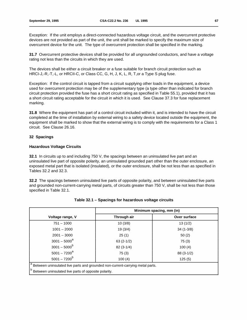
September 29, 1995 CSA-C22.2 No. 236 Ç UL 1995 67
Exception: If the unit employs a direct-connected hazardous voltage circuit, and the overcurrent protectivedevices are not provided as part of the unit, the unit shall be marked to specify the maximum size ofovercurrent device for the unit. The type of overcurrent protection shall be specified in the marking.
31.7 Overcurrent protective devices shall be provided for all ungrounded conductors, and have a voltagerating not less than the circuits in which they are used.
The devices shall be either a circuit breaker or a fuse suitable for branch circuit protection such as HRCI-J,-R,-T,-L, or HRCII-C, or Class CC, G, H, J, K, L, R, T,or a Type S plug fuse.
Exception: If the control circuit is tapped from a circuit supplying other loads in the equipment, a deviceused for overcurrent protection may be of the supplementary type (a type other than indicated for branchcircuit protection provided the fuse has a short circuit rating as specified in Table 55.1), provided that it hasa short circuit rating acceptable for the circuit in which it is used. See Clause 37.3 for fuse replacementmarking.
31.8 Where the equipment has part of a control circuit included within it, and is intended to have the circuitcompleted at the time of installation by external wiring to a safety device located outside the equipment, theequipment shall be marked to show that the external wiring is to comply with the requirements for a Class 1circuit. See Clause 26.16.
32 Spacings
Hazardous Voltage Circuits
32.1 In circuits up to and including 750 V, the spacings between an uninsulated live part and anuninsulated live part of opposite polarity, an uninsulated grounded part other than the outer enclosure, anexposed metal part that is isolated (insulated), or the outer enclosure, shall be not less than as specified inTables 32.2 and 32.3.
32.2 The spacings between uninsulated live parts of opposite polarity, and between uninsulated live partsand grounded non-current-carrying metal parts, of circuits greater than 750 V, shall be not less than thosespecified in Table 32.1.
Table 32.1 – Spacings for hazardous voltage circuits
Voltage range, V Through air Over surface
Minimum spacing, mm (in)
751 – 1000 10 (3/8) 13 (1/2)
1001 – 2000 19 (3/4) 34 (1-3/8)
2001 – 3000 25 (1) 50 (2)
3001 – 5000 63 (2-1/2) 75 (3)a
3001 – 5000 82 (3-1/4) 100 (4)b
5001 – 7200 75 (3) 88 (3-1/2)a
5001 – 7200 100 (4) 125 (5)b
Between uninsulated live parts and grounded non-current-carrying metal parts.a
Between uninsulated live parts of opposite polarity.b

68 CSA-C22.2 No. 236 Ç UL 1995 September 29, 1995
32.3 The spacings on the components in the control system, which is derived from a current transformersensing the motor compressor current, shall be judged on the basis of the maximum available voltage atthe component with the motor-compressor operating at rated load current. See Clause 32.4.
32.4 Provision shall be made for limiting the voltage in the control assembly (see Clause 32.3) resultingfrom an open secondary circuit of a remote current transformer, to a voltage for which the controlcomponents in this circuit are acceptable. The open secondary circuit may result from an open remoteshunt resistor or from a disconnected or broken conductor at the connection to the control circuit.

September 29, 1995 CSA-C22.2 No. 236 Ç UL 1995 69
Table 32.2 – Minimum spacings at locations other than electric heating elements
Rating Minimum spacing mm (in)d
VA Volts mm in mm in mm in
Through air, Over surface To enclosuree a
0–2000 0–300 3.2 1/8 6.3 1/4 6.3 1/4b
More 0–150 3.2 1/8 6.3 1/4 12.5 1/2c
than 151–300 6.3 1/4 9.5 3/8 12.5 1/2
2000 301–750 9.5 3/8 12.5 1/2 12.5 1/2
These spacings do not apply to an individual enclosure of a component part within an outer enclosure or cabinet.a
If over 300 V, the spacings in the last line of the Table apply.b
The spacings between wiring terminals of opposite polarity or between a wiring terminal and ground shall be not less thanc
6.3 mm (1/4 in), except that if short circuiting or grounding of such terminals will not result from projecting strands of wire,the spacing need not be greater than that given in the above Table. Wiring terminals are those connected in the field andnot factory-wired.
The spacings at an individual component part are to be judged on the basis of the total measured volt-ampered
consumption of the load or loads, which the components control. For example, a component that controls the compressormotor is judged on the basis of the measured volt-amperes of the compressor motor. A component that controls loadsin addition to the compressor motor is judged on the basis of the sum of the volt-amperes of the loads so controlled, exceptthat in a component that independently controls separate loads is judged on the basis of the volt-amperes of the larger load.The volt-ampere values for the load referred to above are to be determined by the marked rating of the load; except thatfor loads that are not required to have a marked rating, the measured input is to be used in determining the volt-amperevalues.
The over surface spacings for glass-insulated terminals of motors may be 3.2 mm (1/8 in) e
where 6.3 mm (1/4 in) is specified in the Table; and may be 6.3 mm (1/4 in) where 9.5 mm (3/8 in) is specified.
Exceptions:
1) The spacings of motor terminals inside a hermetic motor enclosure may be one-half of those indicated in the Table,except that the over surface spacings may be 2.4 mm (3/32 in) where 6.3 mm (1/4 in) is specified.
2) The above spacing requirements do not apply to the inherent spacings (internal) of a component part of the unit forwhich spacing requirements have been judged on the basis of the component standard.
3) At closed-in points only, such as the screw and washer construction of an insulated terminal mounted in metal, aspacing of not less than 1.2 mm (3/64 in) is acceptable, if the potential involved is 300 V or less, and a spacing of notless than 6.4 mm (1/4 in) is acceptable if the potential is 300–750 V.
4) The spacings "to enclosure" are not to be applied to an individual enclosure of a component within an outerencounter or cabinet.

70 CSA-C22.2 No. 236 Ç UL 1995 September 29, 1995
Table 32.3 – Minimum spacings at electric heating elementsa,c
Description of spacing mm in
Potential Spacinginvolved V
Between uninsulated live parts of opposite polarity; and between an 0–250 1.6 1/16uninsulated live part and a dead metal part, other than the enclosure, thateither is exposed to contact by persons or may be grounded 251–600 6.4 1/4b b
Between a live part and the enclosure 0–600 6.4 1/4
These spacings are applicable only to parts of the heating element and its terminals located inside the conditioned (heateda
or cooled) air handling compartment. If an uninsulated live part is not rigidly supported, or if a movable dead metal part isin proximity to an uninsulated live part, the construction shall be such that at least the minimum spacing is maintained underall operating conditions and under all normal conditions of handling. Spacings at a thermal cutoff shall comply with Table32.2.
A spacing of not less than 1.6 mm (1/16 in) is permissible at a heating element rated for 300 V or less.b
Metal-sheathed heater elements that have spacings at terminations between live parts and noncurrent-carrying metal partsc
less than 3.2 mm (0.13 in), (6.3 mm (0.25 in) for 300–600 V), but not less than 1.6 mm (0.06 in) (3.2 mm (0.13 in) for300–600 V) shall be sealed against moisture.
32.5 If higher than rated potential is developed in a motor circuit through the use of capacitors, the ratedvoltage of the system is to be assumed for the evaluation of spacings. However, if the developed steadystate potential determined under normal operating conditions exceeds 500 V, the developed potential is tobe used in evaluating spacings for the parts affected.
32.6 An insulating liner or barrier of vulcanized fibre, varnished cloths, mica, phenolic composition, orsimilar material, employed where spacings would otherwise be insufficient, shall be not less than 0.7 mm(0.028 in) thick.
Exceptions:
1) A liner or barrier not less than 0.3 mm (0.013 in) thick may be used in conjunction with an air spacingof not less than 1/2 of the through air spacing required. The liner shall be located so that it will not beoxidized or otherwise deteriorated by arcing.
2) Insulating material less than 0.7 mm (0.028 in) thick may be used, if it has insulating, physical, andflammability properties equivalent to those of the materials specified in the above Clause.
Extra-Low-Voltage Circuits
32.7 For a safety circuit, spacings shall be as follows, if operation of the product with a short circuit orgrounded circuit may result in unsafe operation of the controlled device.
a) The spacing between uninsulated live parts and the walls of a metal enclosure, including conduitfittings, etc, shall not be less than 3.2 mm (1/8 in).
b) The spacing between wiring terminals intended for connection of Class 1 wiring, irrespective ofpolarity, and between wiring terminals and metal parts (including the enclosure) that may be groundedwhen the device is installed, shall be not less than 6.3 mm (1/4 in).

September 29, 1995 CSA-C22.2 No. 236 Ç UL 1995 71
c) The spacing between uninsulated live parts, irrespective of polarity, and between uninsulated liveparts and metal parts, other than the enclosure, which may be grounded when the device is installed,shall be not less than 0.8 mm (1/32 in) provided that the parts are constructed in such a way thatspacings are maintained.
32.8 For nonsafety circuits, spacings are not specified.
33 Refrigerant, hot water, and steam coils
General
33.1 Refrigerant-containing parts shall comply with the following:
a) they shall be constructed of corrosion-resistant material, or shall be plated, dipped, coated, orotherwise treated to resist external corrosion;
b) except as stated in Item (c), tubing used to connect refrigerant-containing components shall complywith the minimum wall thickness requirements of Table 33.1 and with the strength requirements ofClause 33.2;
c) tubing used in the construction of refrigerant-containing parts, such as an evaporator or condensercoil, that is adequately protected by the inherent construction, shall comply with the strengthrequirements specified in Clause 33.2.
Table 33.1 – Tubing wall thickness
Minimum wall thickness, mm (in)a
Outside diameter Copper Steel
Protected Unprotected
6.35 (1/4) 0.62 (0.0245) 0.67 (0.0265) 0.64 (0.025)
7.94 (5/16) 0.62 (0.0245) 0.72 (0.0285) 0.64 (0.025)
9.53 (3/8) 0.62 (0.0245) 0.72 (0.0285) 0.64 (0.025)
12.70 (1/2) 0.62 (0.0245) 0.72 (0.0285) 0.64 (0.025)
15.88 (5/8) 0.80 (0.0315) 0.80 (0.0315) 0.81 (0.025)
19.05 (3/4) 0.80 (0.0315) 0.98 (0.0385) 0.81 (0.032)
22.23 (7/8) 1.04 (0.0410) 1.04 (0.0410) 1.17 (0.032)
25.40 (1) 1.17 (0.0460) 1.17 (0.0460) 1.17 (0.046)
28.58 (1-1/8) 1.17 (0.0460) 1.17 (0.0460) 1.17 (0.046)
31.75 (1-1/4) 1.28 (0.0505) 1.28 (0.0505) 1.17 (0.046)
34.93 (1-3/8) 1.28 (0.0505) 1.28 (0.0505) 1.58 (0.046)
38.10 (1-1/2) 1.41 (0.0555) 1.41 (0.0555) 1.58 (0.062)
41.3 (1-5/8) 1.410 (0.0555) 1.410 (0.0555) – (0.062)
54.0 (2-1/8) 1.626 (0.0640) 1.626 (0.0640) – –
66.7 (2-5/8) 1.880 (0.0740) 1.880 (0.0740) – –
(Continued)

72 CSA-C22.2 No. 236 Ç UL 1995 July 31, 1998
Table 33.1 – (Concluded)
Nominal wall thickness of tubing will have to be greater than the thickness indicated to maintain the minimum walla
thickness.
Note: "Protected" implies that the tubing is shielded by the cabinet or assembly, to the extent that unintended damagecaused by objects such as tools falling on or otherwise striking the tubing during handling and after installation of theunit, is prevented. This protection may be provided in the form of baffles, channels, flanges, perforated metal, orequivalent means. If a cabinet is employed for the intended installation of a unit, the tubing is considered shielded.Tubing not so shielded is considered to be unprotected with respect to Table 33.1.
33.2 All parts of equipment subject to a refrigerant pressure shall have sufficient strength to withstand thepressure test requirements specified in the Strength Test, Section 61. The test pressure shall be the higherof:
a) five times the maximum normal working pressure, see Clause 33.6, or
b) three times the maximum abnormal pressure, see Clause 33.7, or
c) five times the minimum design pressure specified in Table 68.1.
Exception No. 1: Pressure vessels that comply with Clause 33.4.
Exception No. 2: Pressure gauges and control mechanisms.
Exception No. 3: A part or a complete system that complies with Section 61A.
Exception No. 4: Liquid chillers employing centrifugal motor compressors shall have sufficient strength towithstand without failure a pressure equal to not less than three times the maximum normal workingpressure, or three times the minimum design pressure specified in Table 68.1, whichever is greater.
33.3 A water coil operating at more than 93EC (200EF) and a steam coil shall withstand a hydrostaticpressure equal to five times the marked operating pressure, without leakage or rupture, when tested asdescribed in Section 61.
33.4 If the equipment includes pressure vessels having an inside diameter over 152 mm (6 in), and aninternal volume over 0.0425 cu m (1.5 cu ft), they shall comply with the Boiler, Pressure Vessel, andPressure Piping Code, CSA Standard B51, and shall be designed, tested, and stamped in accordance withthe ASME Unfired Pressure Vessel Code for a design pressure in compliance with the requirements of theStrength Test specified in Section 61.
33.5 The tubing connections of dissimilar metals, such as aluminum and copper, shall be protectedagainst moisture to minimize galvanic action.

July 31, 1998 CSA-C22.2 No. 236 Ç UL 1995 72A
33.6 For the purpose of Clause 33.2, the maximum normal working pressure shall be the following:
a) for high side parts, the highest of the following:
1) the maximum condensing pressure when the equipment is operated under the most severecondensing conditions for which it is intended, but in any case for equipment with an air-cooledcondenser, at a condenser air inlet temperature of not less than 40EC (104EF), and, for equipmentwith a water-cooled condenser, at condenser water temperatures not less than 26.7EC (80EF) at theinlet and 37.8EC (100EF) at the outlet; and at the most severe evaporator condition for which it isintended, but in any case with air inlet conditions of not less than 26.7EC (80EF) dry bulb, and 19.4EC(67EF) wet bulb;
2) the marked design pressure; or
3) the condensing pressure of water-cooled equipment that does not have a pressure-limiting deviceif the water flow is stopped; and
b) for low side parts, the highest of the following:
1) the evaporator pressure when the equipment is operated as specified in Item (a)(i); or

72B CSA-C22.2 No. 236 Ç UL 1995 July 31, 1998
No Text on This Page

July 31, 1998 CSA-C22.2 No. 236 Ç UL 1995 73
2) the vapour pressure of the refrigerant at 21.1EC (70EF); or
3) the evaporator pressure when it is exposed to some temperature above 21EC (70EF) for which itis designed; or
4) the marked design pressure.
33.7 The maximum abnormal working pressure shall be as follows:
a) for high side parts, the pressure developed in the fan motor and water failure tests;
b) for low side parts, the highest of the following:
1) the pressure that developed in the motor and water failure test(s), including the pressure thatresults when the compressor is stopped;
2) the rating or setting of a pressure relief or rupture member fitted in the low side; or
3) if the high side operating pressure is limited by a pressure relief valve that is vented into the lowpressure side of the system, the value of the low side pressure that results from the action of thepressure relief valve.
33.8 Pressure vessels with a design pressure not exceeding 103kPa (15 psig) are not required to bedesigned, tested, and stamped in accordance with the Boiler, Pressure Vessel, and Pressure Piping Code,CSA Standard B51 and the ASME Unfired Pressure Vessel Code.
33.9 ASME pressure vessels bearing the code U symbol with a working pressure not less than thatrequired by Clause 33.2 are acceptable without test.
Refrigerant Pressure Relief
33.10 Equipment shall have protective means such as a fusible plug, a rupture member, soldered orbrazed tubing joints, special terminals, or pressure relief valves, or shall be so constructed that some partof the system will safely relieve the pressure in case of fire.
Exception: A means for relieving pressure is not required on a forced air-cooled condenser in which theonly refrigerant-containing component is tubing, and which is not equipped with shutoff valves.
33.11 If the refrigerating system includes a liquid-containing pressure vessel with an inside diameter over76.2 mm (3 in) but not over 152 mm (6 in), and which can be isolated by valves from the other parts of theequipment, the pressure vessel shall be protected by
a) a rupture member or pressure relief valve that will relieve the pressure at not more than 40% of thepressure defined in Clause 33.2, or 40% of the pressure it is capable of withstanding, as determined bythe test in Section 61; or
b) a fusible plug, provided that the critical pressure of the refrigerant used does not exceed the relievingpressure specified in Item (a), or that the saturation pressure of the refrigerant used, at the temperaturemarked on the plug, does not exceed the relieving pressure specified in Item (a) above.

74 CSA-C22.2 No. 236 Ç UL 1995 July 31, 1998
33.12 Constructions that may be acceptable for relieving pressure in case of fire include those indicated inClause 33.10, as well as gasketed joints and elastomeric insulators for terminals of hermetic compressors.
33.13 A stop valve or shutoff valve shall not be located between any pressure relief device or fusible plug,etc, and the part or parts of the system protected thereby.
33.14 All pressure relief means shall be connected adjacent to or directly to the pressure vessel or parts ofthe system protected. Pressure relief devices shall be connected above the liquid refrigerant level andinstalled to make them accessible for inspection and repair and to protect them from conditions that couldcause them to malfunction.
Exception: Fusible plugs may be located either above or below the liquid refrigerant level.
33.15 Rupture members shall burst at a pressure within 5% of the nominal pressure marked on the device,at the temperature with which it is marked, when tested in accordance with Section 62, Rupture MemberTest.
33.16 Fusible plugs shall operate at a temperature within 5.6EC (10EF) of the marked temperature rating,when tested in accordance with Section 63.
33.17 A pressure vessel that has an inside diameter greater than 76 mm (3 in) and that cannot containliquid refrigerant, shall be protected by a pressure relief device or fusible plug having sufficient dischargecapacity to relieve the pressure developed in the vessel, under fire conditions, and prevented fromexceeding a value corresponding to one-third the ultimate strength of the vessel.
33.18 A positive displacement compressor operating at pressures exceeding 103 kPa (15 psig), and havinga displacement exceeding 0.02 m /s (50 cfm) shall be equipped with a pressure relief device having the3
capacity and the pressure setting necessary to prevent rupture of the compressor. The pressure reliefdevice shall be located between the compressor and stop valve on the discharge side. Discharge from thedevice may be vented to the atmosphere or into the low pressure side of the system.
33.19 Pressure relief devices may discharge into the low pressure side of the system, provided that theyare not appreciably affected by back pressures, and provided that the low pressure side of the system isequipped with its own pressure relief device. The low side pressure relief devices shall have capacity toprotect either the pressure vessels that are relieved into the low pressure side of the system, or all pressurevessels on the low side of the system, whichever relieving capacity is the largest.
33.20 On liquid chillers employing centrifugal motor compressors, the pressure relief device for thehigh-side pressure vessels may be in the low-side of the system, provided
a) it can be established that the clearances between the capacity control vanes and their housings andother fixed openings between the high-side and low-side are sufficient to provide the relief capacityrequired for high-side pressure vessels; and
b) the low-side pressure relief device has a relief capacity at least equal to the sum of the capacitiesrequired for all pressure vessels on high-side and low-side.

July 31, 1998 CSA-C22.2 No. 236 Ç UL 1995 74A
33.21 Calculation of the discharge capacity of a rupture member or fusible plug shall be in accordancewith the Mechanical Refrigeration Code, CSA Standard B52 and the Safety Code for MechanicalRefrigeration, ANSI/ASHRAE 15-1994.
33.22 A pressure relief valve shall be sealed at a start-to-discharge pressure not exceeding the markedworking pressure of the pressure vessel it protects.

74B CSA-C22.2 No. 236 Ç UL 1995 July 31, 1998
No Text on This Page

July 31, 1998 CSA-C22.2 No. 236 Ç UL 1995 75
Exception: A pressure relief valve for a pressure vessel that does not have a marked working pressureshall be sealed at a start-to-discharge pressure that corresponds to no more than one-fifth of the ultimatestrength of the pressure vessel.
33.23 Where the pressure relief means is provided by a rupture member, the nominal rated rupturepressure of the member shall not exceed the marked design pressure of the vessel protected, or one-fifthof the ultimate strength of pressure vessels that do not have a marked design pressure.
Refrigerant Pressure-Limiting Device
33.24 A pressure-limiting device shall be installed on
a) deleted
b) all units that are designed for use in systems containing 10 kg (22 lbs) or more of refrigerant or thatemploy a receiver or condenser-receiver with a capacity to accept 10 kg (22 lbs) of refrigerant withoutthe liquid occupying more than 90 per cent of the volume when the refrigerant temperature is 32.2EC(90EF);
c) all condensing units that are not subjected to operational tests (where the refrigerant circuit isoperated to obtain pressure – See Table 38.1) with a compressor motor rated at more than 1horsepower (746 W output).
Exception: A pressure-limiting device need not be provided if the condensing unit
1) is intended for air-conditioning use; and
2) contains a hermetic refrigerant motor-compressor having a steel shell that is provided with aninternal bleeder valve that relieves discharge pressure into the low-pressure side of the refrigerantsystem.
33.25 Deleted
33.26 A pressure-limiting device shall be installed on all compressor units and compressor-evaporatorunits.
33.27 The adjustable cutout pressure setting of a pressure-limiting device shall not exceed
a) one-third of the ultimate strength of high side refrigerant containing parts provided this setting doesnot exceed 90 percent of the setting of the pressure relief device; or
b) 110 percent of the design pressure marking on the unit name plate for units that are (1) notsubjected to operational tests (where the refrigerant circuit is operated to obtain pressure - See Table38.1) or (2) water cooled.

76 CSA-C22.2 No. 236 Ç UL 1995 July 31, 1998
Exception: On liquid chillers employing centrifugal motor compressors, if the pressure relief device is set inthe low side of the system the maximum cutout pressure to which a pressure-limiting device may be readilyadjusted by the adjusting means provided may be more than 90 percent but not more than 100 percent ofthe following, whichever is lowest:
a) except for ASME Code U-symbol pressure vessels, see Item (b), one-third of the pressurecorresponding to the ultimate strength of high-side refrigerant-containing parts;
b) the marked design pressure of high-side pressure vessels.
33.28 Deleted
33.29 There shall be no stop valves between the pressure-limiting device and the compressor.
33.30 Deleted
34 Heat pump water heating equipment
General
34.1 The following additional requirements apply specifically to heat pump water heating equipment. Suchequipment shall also comply with all of the applicable requirements of this Standard.
Heat Exchanger
34.2 Heat exchangers intended for connection to a potable water system shall be of double wallconstruction and marked in accordance with Clause 37.11(a). Such design shall incorporate either avented interface or redundant construction to prevent the leakage of refrigerant into potable water.
34.3 Heat exchangers may be of single wall construction provided they are not intended for connection to apotable water system, and shall be marked in accordance with Clause 37.11(b).
34.4 In accordance with Clause 34.2, a vented interface shall be maintained at near atmospheric pressure,with the venting path continuous over the entire length of the heat exchanger. The continuity of the ventingpath is determined by use of water at a pressure not higher than 62 kPa (10 psig).
34.5 In accordance with Clause 34.2, heat exchangers shall have sufficient strength to withstand apressure of not less than five times the maximum rated refrigerant design pressure for the refrigerant side,with the water side maintained at atmospheric pressure.
34.6 In accordance with a vented interface (Clause 34.2) heat exchangers shall have sufficient strength towithstand not less than 1-1/2 times the maximum rated design pressure for the refrigerant side. SeeClause 64.18.
34.7 Heat exchangers employing a redundant double wall construction per Clause 34.2 shall havesufficient strength for each separate wall to withstand a pressure of not less than five times the maximumrated refrigerant design pressure with the outer side maintained at atmospheric pressure.
34.8 The water side of a heat exchanger shall have sufficient strength to withstand a pressure of not lessthan 2.1 MPa (300 psig). See Clause 64.18.

September 29, 1995 CSA-C22.2 No. 236 Ç UL 1995 77
Storage Tank
34.9 Storage tanks shall meet the requirements of the Standard for Construction and Test of ElectricStorage-Tank Water Heaters, CSA Standard C22.2 No. 110 and Household Electric Storage Tank WaterHeaters, UL 174.
Water Temperature Control
34.10 A heat pump water heater or desuperheater shall be equipped with a water-temperature-regulatingcontrol, so that the water in the tank, if supplied by the manufacturer as part of the water heating system, orat the outlet, will not attain a temperature of more than 85EC (185EF).
34.11 In addition to the temperature-regulating control required by Clause 34.10, awater-temperature-limiting control shall be provided to interrupt the electrical supply to the water heatingsystem to prevent the temperature in the tank or at the outlet from exceeding 99EC (210EF), when theequipment is tested under the applicable conditions of Section 64. This control shall not function undernormal conditions as specified in Clauses 64.5 and 64.6.
34.12 Controls limiting water temperature for the heat pump shall be temperature- or pressure-actuatedand located electrically as specified in Clauses 34.15 and 34.16.
Exception: If the unit complies with the water temperature test as noted in Clause 64.11 when all operating,regulating and limiting controls are bypassed, and the compressor motor is provided with a direct line breakoverload protector, the construction need not comply with the above.
34.13 Controls shall comply with the applicable requirements for their intended function(s), as specified inthe Standard for Temperature-Indicating and -Regulating Equipment, CSA Standard C22.2 No. 24, andTemperature Indicating and Regulating Equipment, Electrical, UL 873.
34.14 Controls shall be integral with the equipment, and shall not be designed to be installed in an existingwater storage tank that is not supplied as part of the packaged heat pump water heater or desuperheater.
34.15 The temperature-limiting control shall have no operating part in common with thetemperature-regulating control mentioned in Clause 34.10.
34.16 If the temperature-limiting control is in the control circuit of a magnetic contactor or relay, such acontactor or relay shall be so wired that it is not actuated by a temperature-regulating control.
UNIT MARKINGS
35 General
35.1 All markings required for compliance with this Standard may need to be in other languages toconform with local language requirements where the product is to be sold.
Note: In Canada there are two official languages, English and French. Appendix A lists some examples of Frenchtranslations.
78 CSA-C22.2 No. 236 Ç UL 1995 July 31, 1998
36 Equipment markings
36.1 The markings in Section 36 may consist of one or more labels, located in a place where readily visibleafter installation, without the use of tools. The markings shall not be affixed to any panel that can beremoved without the use of tools except that,
a) a marking may be located on a panel that would be removed for installation or service, providing thatthe panel must be in place for the intended operation of the equipment;
b) if the nameplate is located on a removable cover, a second nameplate with the electrical rating,model designation, and a note to see marking on the cover shall be secured on the inside of the unit;
c) the markings on a unit intended for built-in installation may be located behind a louvred panel or grillethat may require tools for removal to gain access to the field wiring compartment.
36.2 The material for the labels shall be of metal or of a type suitable for outdoor or indoor use, asapplicable.
36.3 The equipment shall be plainly marked, in a permanent manner, with the following:
a) the manufacturer's or private labeler's name, trademark, tradename, or other identifying symbol;
b) the catalogue number, style, model, or other type designation;
c) voltage;
d) number of phases, unless for single-phase operation;
e) frequency in hertz;
f) the horsepower (see Clause 36.18) and full load amperes of each motor, except for hermeticallysealed compressor motors, which shall be rated in locked rotor and rated load amperes (see Clause36.10), and motors smaller than 1/8 horsepower, which may be rated in watts or amperes;
g) heater input amperes or watts at marked voltage. See also Clause 36.3(t) for separable heaterelement assemblies;
h) minimum power supply circuit ampacity for each hazardous voltage circuit which powers more thanone motor or a motor and other loads rated 1.0 A. or more as shown in Figure 36.1 (see Clause 36.14);

July 31, 1998 CSA-C22.2 No. 236 Ç UL 1995 78A
i) for each hazardous voltage circuit which powers more than one motor or a motor and other loadsrated 1.0 A. or more as shown in Figure 36.2 (see Clause 36.15) "MAX. FUSE______", or "MAX. CKT.BKR.______ (HACR type per NEC)" or equivalent. See Clause 36.17 for requirements when otherwording is used.
j) the type of refrigerant for operation, and the weight of factory refrigerant charge (self-contained unitsonly), if the equipment is intended to employ refrigerant;
Exception: Unit coolers that do not contain a compressor (such as fan coil units or forced air cooledcondensers) need not be marked with the kind of refrigerant if a tag is provided indicating that the designpressure(s) marked on the unit shall not be less than the design pressures marked on the compressor orcondensing unit or as outlined in Clause 6.8 of CAN/CSA B52 and Section 8.2 of ANSI/ASHRAE 15-92 forthe refrigerant used in the system. The marking shall also indicate that after

78B CSA-C22.2 No. 236 Ç UL 1995 July 31, 1998
No Text on This Page
September 29, 1995 CSA-C22.2 No. 236 Ç UL 1995 79
charging, the equipment shall be marked with the refrigerant and the oil used. Compatibility with analternate refrigerant may need to be determined if the unit contains any gaskets.
k) the design pressures for the high and low pressure sides, if intended to employ refrigerant;
l) the date or other dating period of manufacture not exceeding any consecutive three months. Forexample, date coding, serial numbers, or equivalent means may be used;
m) the maximum outlet air temperature for units with electric resistance heaters;
n) the range of external static pressures, or maximum external static pressure at which the unit wastested (add-on heat pumps and units with electric resistance heaters only);
o) the minimum spacing to combustible surfaces for units with electric resistance heaters;
p) the minimum refrigerant design pressure and the type of the remote condenser (air-, water-, orevaporatively-cooled), if the unit is intended to be used with a remote condenser;
q) the marking "OUTDOOR USE" or equivalent, if the equipment is intended to be used and meets theapplicable requirements for outdoor use;
r) "WARNING: RISK OF ELECTRIC SHOCK. CAN CAUSE INJURY OR DEATH: DISCONNECT AllREMOTE ELECTRIC POWER SUPPLIES BEFORE SERVICING", in letters not less than 3.2 mm(1/8 in) high, or the equivalent . For equipment with multiple hazardous voltage power supplies, thismarking shall be located on all panels providing access to hazardous voltage uninsulated live parts;
s) "CAUTION: MOUNT WITH THE LOWEST MOVING PARTS AT LEAST 2.4 m (8 ft) ABOVE FLOOROR GRADE LEVEL", or the equivalent, if required under Clause 11.2;
t) the name and rating plate of a unit with a field-installed element assembly referred to in Clause 15.3shall include the following or the equivalent:
1) list all of the manufacturer's name(s) and model designations of all of the heater elements thatcan be installed in the unit;
2) have provision for:
i) checking off the model designation of the heater that is installed; and
ii) indicating the electrical ratings (volts, phase(if three phase only), and amperes or watts) of theunit with the heater installed; and
3) if the actual heater element rating is not included on the equipment nameplate and if the heaterelement nameplate is not accessible for viewing after installation of the elements, the followingadditional marking shall appear, and should be applied on the exterior of that section of the unit thathouses the field-installed heater elements: "FOR ACTUAL HEATER ELEMENT RATING SEEELEMENT MARKING INSIDE", or the equivalent;
u) a distinctive marking to identify the place of manufacture, if produced at more than one factory;
v) units with hot water coils shall be marked with the maximum inlet water temperature;

80 CSA-C22.2 No. 236 Ç UL 1995 July 31, 1998
w) units with hot water or steam coils shall be marked with the maximum pressure at which a water coilemploying heated water at a temperature exceeding 93EC (200EF) or a steam coil is intended to beused;
x) where required by Clause 64.8, the following marking or equivalent, "CAUTION: USE TIME DELAYFUSES".
Exception: For individual loads rated at less than 1 A, the electrical ratings need not be marked on the unit.
36.4 For cord-connected units, the total input current in amperes shall be marked on the unit.
36.5 A single overall ampere rating, rather than individual ratings for the various loads, may be marked onthe unit nameplate provided that
a) the unit is rated single phase, ac; and
b) the single ampere rating does not exceed 12 A at 208-240 V or 16 A at 120 V, with the correspondingmaximum ratings of the power supply overcurrent protective devices and minimum power supply circuitampacities of 15 A and 20 A, respectively.
36.6 Unless it is otherwise obvious, equipment that depends upon a proper location or position foracceptable operation shall be marked (for example, "TOP" or "BOTTOM"), to indicate the position in whichit shall be installed.
36.7 The high-side, if applicable, and low-side design pressures indicated on the nameplate of the unitshall be as follows:
a) no less than the values shown in Table 68.1 for the type of refrigerant used; and
b) no more than the pressures at which the assembled unit or components or both are tested forleakage (see Clause 68.1).
36.8 Units with star-delta start motor-compressors shall include the locked rotor current for the star anddelta connections.
36.9 With reference to Clause 10.5, if the motor-compressor controller and overload protection are notprovided by the chiller manufacturer, the nameplate shall so indicate. The nameplate shall include thedesignation of the chiller manufacturer's specification for these remote components.
36.10 For a hermetic motor compressor, the branch circuit selection current in amperes shall also bemarked, if required, in accordance with Clause 36.11 and provided that it meets the requirements of theCanadian Electrical Code, Part I, CSA Standard C22.1, and Article 440-4(c) of the National Electrical Code,ANSI/NFPA No. 70-1993.

July 31, 1998 CSA-C22.2 No. 236 Ç UL 1995 80A
36.11 A branch circuit selection current rating in amperes shall be marked on the product nameplate if athermal protector or protective system allows a continuous current greater than 156 percent of the ratedload current
a) of the motor compressor as marked on the product nameplate; or
b) of the product when marked with a single overall ampere rating per Clause 36.5. The marked valueof the rating shall be at least 64 per cent of the compressor maximum continuous current rating.

80B CSA-C22.2 No. 236 Ç UL 1995 July 31, 1998
No Text on This Page

September 29, 1995 CSA-C22.2 No. 236 Ç UL 1995 81
Determination of Rating
36.12 The ratings of motors and other loads marked on the equipment shall be used to determineminimum circuit ampacity (Clause 36.14) and rating of the hazardous voltage supply circuit overcurrentprotective device (Clause 36.15). Remote loads, such as motors and heaters supplied from the unit, shallalso be included in the determination. If the product nameplate is marked with a branch circuit selectioncurrent rating, the branch-circuit selection current is the value in amperes to be used instead of the rated-load current.
36.13 The minimum rated currents marked on the equipment shall be as follows:
a) for motor loads, no less than
1) 95 per cent of the input measured during the heating and cooling operation tests; or
2) the input measured during the input tests, Clause 39.1; and
3) 64 per cent of the compressor maximum continuous current rating;
b) for electric resistance heaters, the ampere or wattage rating marked on the unit nameplate shall notdiffer from that measured during the input test (see Clause 39.2) by more than ± 5 percent.
Minimum Circuit Ampacity
36.14 The minimum circuit ampacity (MCA) required by Clause 36.3(h) shall be determined as follows. Allconcurrent load conditions are to be considered in the determinations, see Figure 36.1. Whichever loadcondition provides the highest value shall be used.
a) For a motor group only, a load consisting of two or more motors, the rated current of the largestmotor or branch circuit selection current, if marked, (see Clauses 36.11 and 36.12), multiplied by 125per cent, added to the rated currents of all of the other motors.
b) For a combination load, a load consisting of one or more motors, electric heaters, and any otherloads, that incorporates one or more compressor motors, the rated current of the largest motorcompressor or branch circuit selection current, if marked, (see Clauses 36.11 and 36.12), multiplied by125 per cent, added to which shall be the value obtained by multiplying the rated current of the electricheaters by 125 per cent, and adding to that total the sum of the ratings of all other loads.
c) For a combination load, a load consisting of one or more motors, electric heaters, and any otherloads, not involving a hermetic refrigerant motor compressor, the sum of the rated currents multiplied by125 per cent.
Exception: The rated current of the heater load may be multiplied by 100 percent, rather than 125 per cent,provided that
1) the rated heater load at a field wiring terminal is 50 kW or more;
2) the minimum conductor size that may be field-connected to such terminal is still to be marked;and
3) the heater element circuits connected to the field wiring terminals are subdivided as specified inClause 30.8 and are arranged to be controlled by one or more temperature-actuated devices toreduce the likelihood of continuous simultaneous operation of all of the element circuits.

82 CSA-C22.2 No. 236 Ç UL 1995 September 29, 1995
Figure 36.1 – Minimum circuit ampacity calculation
On equipment with multiple modes of operation, every mode shall be considered for each individual fieldwired hazardous voltage circuit. Whichever load condition provides the highest value shall be used forClause 36.14, in the applicable circuit.
(Clause 36.14(a))
MCA = (1.25× LOAD1) + LOAD2
(Clause 36.14(b))
MCA = (1.25 × LOAD1) + (1.25* × LOAD3) + LOAD2 + LOAD4
(Clause 36.14(c))
MCA = 1.25 × (LOAD1 + LOAD2 + LOAD4) + (1.25* × LOAD3)
where
MCA = Minimum circuit ampacity per Clause 36.14
LOAD1 = Current of largest motor or branch circuit selection current, if marked, (see Clauses 36.11 and36.12)
LOAD2 = Sum of currents of all motors not including largest motor
LOAD3 = Current of electric resistance heater
LOAD4 = Any other load rated 1.0 A or more
*If exception in Clause 36.14 applies, use 1.0 instead of 1.25.
Rating of Overcurrent Protective Devices
36.15 The maximum current rating of overcurrent protection for each hazardous voltage circuit, as requiredby Clause 36.3(i), for units having more than one motor, or one or more motors and other loads, operatedfrom a single supply source, shall be determined as follows. All concurrent load conditions shall beconsidered in the determinations.
The rated current of the largest motor, compressor or other motor or branch circuit selection current, ifmarked, (see Clauses 36.11 and 36.12) shall be multiplied by 2.25. To that is to be added the rated currentof any other concurrent loads involved in the circuit. Whichever load condition provides the highest valueshall be used for Clause 36.3(i). See Figure 36.2.

July 31, 1998 CSA-C22.2 No. 236 Ç UL 1995 83
Figure 36.2 – Maximum rating of overcurrent protective device calculation
On equipment with multiple modes of operation, every mode shall be considered for each individualfield-wired hazardous voltage circuit. Whichever load condition provides the highest value shall be used forClause 36.15, in the applicable circuit.
MOP = (2.25 × LOAD1) + LOAD2 + LOAD3 + LOAD4
where
LOAD1 = current of largest motor (compressor or other motor) or branch circuit selection current, ifmarked, (see Clauses 36.11 and 36.12)
LOAD2 = sum of current for all other motors
LOAD3 = current of electric resistance heater
LOAD4 = any other load rated 1.0 A or more
MOP = maximum rating of overcurrent protective device
36.16 If the value of the rating determined by applying Clause 36.15 does not equal a standard currentrating of overcurrent protective device, the marked maximum rating is to be the next lower standard rating.
Exceptions:
1) The marked maximum rating of the overcurrent protective device shall be the standard rating nexthigher than the computed value, if the next lower standard rating is less than 125 percent of thecurrent rating of an electric heater load, when such a heater is involved.
2) If the computed value of the overcurrent protective device is less than the minimum ampacity ofthe supply circuit, as determined in accordance with Clause 36.14, the marked rating of the deviceshall be increased to the largest standard overcurrent protective device rating appropriate for themarked minimum circuit ampacity.
3) If the marked minimum circuit ampacity does not correspond to a standard protective devicerating, the next higher standard rating of the protective device may be marked, if this rating does notexceed 800 A.
36.17 If the marking indicated in Clause 36.3(i) specifies a maximum overcurrent protective device or circuitbreaker, the unit shall comply with Item (a) or with all of Items (b) to (d) as specified below:
a) The internal motor circuit involved is protected by
1) a circuit breaker, provided as part of the equipment, that has been determined by short-circuittests on the circuit breaker in combination with the motor circuit wiring and components; or

84 CSA-C22.2 No. 236 Ç UL 1995 July 31, 1998
2) a fuse, provided as part of the equipment, of a type and rating acceptable to provide short-circuitand ground-fault protection for the motor circuit wiring and components.
b) Each motor overload-protective device can be considered to comply with the requirements of theLimited Short-Circuit Test, Section 55.
c) The marked maximum rating of the overcurrent protective device does not exceed 225 percent of thefull-load current rating of any motor controller protected against short circuits and ground faults by thatovercurrent device.
d) The marked maximum rating of the overcurrent protective device does not exceed 180 percent of theampacity of motor-circuit conductors protected against short circuits and ground faults by thatovercurrent-protective device. Ampacities of conductors are determined from Table 20.1.
Exception: Equipment operated from a supply source(s) and each source contains a single load (egcompressor, motor, electric resistance heater, control system) need not comply with Clause 36.17.
36.18 The horsepower rating for motors other than hermetically sealed compressors is not required on theunit nameplate, provided the nameplate is marked with a minimum disconnect size rating. The currentrating in amperes of the disconnect size shall be at least 115% of the sum of the following unit nameplatemarked loads (see Clause 36.13):
a) motor-compressor rated load current or branch-circuit selection current, whichever is greater; and
b) the rated current for other controlled loads.
37 Other markings
37.1 The markings in Clause 37 may appear on label(s) or on wiring diagram(s). Material may be paper orthe equivalent.
37.2 A unit requiring field-provided motor overload protection, under the provisions of Clause 23.6, shallhave markings readily visible stating this fact, and indicating that the motor overload protective devices shallbe rated or selected in compliance with the applicable installation code, as specified by the authority havingjurisdiction.
37.3 A replacement marking shall be provided for a replaceable fuse or overload protective heaterelement provided as a part of a product or remote control assembly. It shall be visible when the cover ordoor of the compartment is opened. This marking shall specify
a) the rating of the fuse in amperes and voltage, and the fuse class, if marked;
b) for supplementary type fuses (see Clause 31.7) the fuse manufacturer's or private labeller's nameand catalogue number; and
c) the manufacturer and model designation of the overload protective heater element.

July 31, 1998 CSA-C22.2 No. 236 Ç UL 1995 84A
37.4 All terminal points where field connections are to be made shall be clearly marked, unless these areapparent.
37.5 If the unit includes a motor that is installed remote from its controller, the rating of the remote motor,the size of the conductors supplying it, and reference to the location of the disconnect device for the remotemotor shall be shown.
37.6 If provisions are made for the connection of an external load such as a cooling tower or evaporatormotor, the maximum load to be connected shall be shown. If provisions are made for the connection of anexternal hazardous voltage switching device such as a thermostat or control switch, the minimum requiredrating for the switching device shall be shown.
37.7 If a unit is controlled by a specific use controller that is not installed on the assembly, a marking shallshow the identifying designation of the controller. The rating of the overcurrent (heater) element to be usedshall be shown when a thermal overload relay is part of the controller.

84B CSA-C22.2 No. 236 Ç UL 1995 July 31, 1998
No Text on This Page

September 29, 1995 CSA-C22.2 No. 236 Ç UL 1995 85
37.8 If a unit is intended to be connected to an extra-low-voltage source, the minimum rating of the supplytransformer shall be shown if a transformer rated 5 VA or more is required.
37.9 Units shall be marked, in the vicinity where field wiring terminates, "USE COPPER SUPPLY WIRES"or the equivalent.
If the product is intended for field connection with aluminum wires, the marking shall additionally so state.
37.10 If the temperature in the terminal box or the compartment intended for the supply connectionsexceeds 75EC (167EF) during the operational tests, a value suitable for the temperature measured shall bemarked.
The marking shall state, "USE CONDUCTORS SUITABLE FOR AT LEAST EC ( EF)" or theequivalent.
37.11 The following applies to heat pump water heating equipment only:
a) Equipment having a heat exchanger complying with Clause 34.2 and 34.4 shall be marked with thefollowing, or the equivalent: "CAUTION: DOUBLE WALL HEAT EXCHANGER, SUITABLE FORPOTABLE WATER CONNECTION".
b) Equipment having a heat exchanger complying with Clause 34.3 shall be marked with the following,or the equivalent: "CAUTION: SINGLE WALL HEAT EXCHANGER, NOT SUITABLE FOR POTABLEWATER CONNECTION".
TESTS
38 General test parameters
38.1 The tests specified in Tables 38.1 and 38.2, denoted by "yes" in the tabulations, apply to the type ofunit indicated. Table 38.1 applies to units, either self-contained equipment or matched systems, thatinvolve compressors. Table 38.2 applies to all other equipment, such as central heating furnaces, wherecompressors are not involved. Only those tests that apply to the intended application of the unit arerequired.
38.2 For the tests specified in Table 38.1, except as otherwise indicated, the inlet air and watertemperatures maintained during the respective tests are to be as shown in Table 38.4. If ambienttemperatures are not specified, the device may be tested at any ambient.
38.3 For the tests specified in Table 38.2, the air inlet temperature maintained during the respective testsshall be 26.7EC (80EF), ±1.1EC (±2EF) dry bulb. The wet bulb temperature is not specified.
If the inlet air temperature is maintained at other than 26.7EC (80EF), ±1.1EC (±2EF), the temperatures inTable 38.5 shall be adjusted accordingly. The temperatures shall not be within 5 percent of the adjustedmaximum temperatures.
38.4 Temperatures shall be determined either by thermocouples or the rise of resistance method. Atemperature shall be considered to be constant when three successive readings taken at 10 min intervalsindicate that stabilized temperatures have been established (no more than a 1 percent net increasebetween the last two readings). If the temperatures measured are within 5 percent of the values specified inTable 38.5, the test shall be continued until two successive 10 min readings indicate constant temperatures.
86 CSA-C22.2 No. 236 Ç UL 1995 September 29, 1995
38.5 Components shall not be overheated, there shall be no risk of electrical shock hazard, and refrigerantshall not be released, when the unit is tested in accordance with Clause 38.1. See Table 38.5. Thetemperatures in Table 38.5 are based on a unit ambient of 26.7EC (80EF).
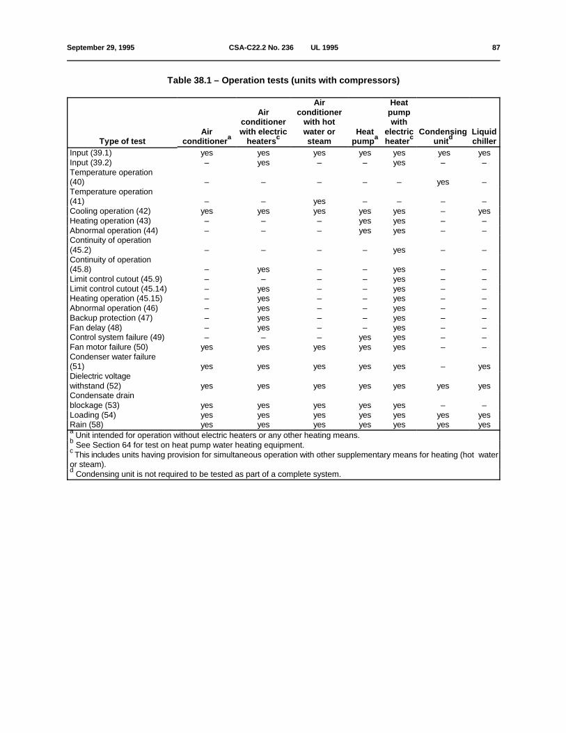
September 29, 1995 CSA-C22.2 No. 236 Ç UL 1995 87
Table 38.1 – Operation tests (units with compressors)
Type of test conditioner heaters steam pump heater unit chillerAir with electric water or Heat electric Condensing Liquid
a
Air conditioner pumpconditioner with hot with
c
Air Heat
a c d
Input (39.1) yes yes yes yes yes yes yesInput (39.2) – yes – – yes – –Temperature operation (40) – – – – – yes –Temperature operation (41) – – yes – – – –Cooling operation (42) yes yes yes yes yes – yesHeating operation (43) – – – yes yes – –Abnormal operation (44) – – – yes yes – –Continuity of operation (45.2) – – – – yes – –Continuity of operation (45.8) – yes – – yes – –Limit control cutout (45.9) – – – – yes – –Limit control cutout (45.14) – yes – – yes – –Heating operation (45.15) – yes – – yes – –Abnormal operation (46) – yes – – yes – –Backup protection (47) – yes – – yes – –Fan delay (48) – yes – – yes – –Control system failure (49) – – – yes yes – –Fan motor failure (50) yes yes yes yes yes – –Condenser water failure (51) yes yes yes yes yes – yesDielectric voltage withstand (52) yes yes yes yes yes yes yesCondensate drain blockage (53) yes yes yes yes yes – –Loading (54) yes yes yes yes yes yes yesRain (58) yes yes yes yes yes yes yes Unit intended for operation without electric heaters or any other heating means.a
See Section 64 for test on heat pump water heating equipment.b
This includes units having provision for simultaneous operation with other supplementary means for heating (hot waterc
or steam). Condensing unit is not required to be tested as part of a complete system.d

88 CSA-C22.2 No. 236 Ç UL 1995 September 29, 1995
Table 38.2 – Operation tets (units without compressors)
Type of test Without supplementary With electric heat With hot water or steamheat
Input (39.1) Yes – Yes
Input (39.2) – Yes –
Temperature Operation (40) Yes – –
Temperature Operation (41) – – Yes
Continuity of operation (45.8) – Yes –
Limit control cutout (45.14) – Yes –
Heating operation (45.15) – Yes –
Abnormal operation (46) – Yes –
Backup protection (47) – Yes –
Dielectric voltage withstand (52) Yes Yes Yes
Condensate drain blockage (53) Yes Yes Yes
Loading (54) Yes Yes Yes
Rain (58) Yes Yes Yes
These tests apply to fan units, fan coil units, room fan heater units, central heating furnaces, and similar fixed electrica
space heating equipment. Such assemblies, tested as part of matched systems (see Table 38.1), need not be individuallytested as noted in this Table.

September 29, 1995 CSA-C22.2 No. 236 Ç UL 1995 89
Table 38.3 – Polymeric material tests
Type of tests Cabinet Structural parts Functional Thermal or accousticalparts material
Flammability:a,b
Source of Ignition
Internal Yes Yes Yes Yes
External Yes Yes
Mold Stress-Relief distortion Yes Yes Yesc c
Accelerated Aging(59.5) Yes Yes
Ultraviolet Light Exposure(65) Yes Yese e
Water Exposure and Immersion(66) Yes Yese e
Tensile Strength Yes Yesd
Flexural Strength Yes Yesd
Izod Impact Yes Yesd
Tensile Impact Yes Yesd
Impact(60) Yes Yes
Loading(54) Yes Yes
Exception: A material having a flame spread rating of not more than 25 when tested as specified in Surface Burninga
Characteristics of Building Materials and Assemblies, CAN/ULC-S102, and the requirements for Standard Method ofTest for Surface Burning Characteristics of Building Materials, UL 723.
See Clause 5.9.1b
See Clause 23.13.1c
See Clause 59.5, Section 65 and 66d
On units marked for outdoor use, where exposed to the effects of ultraviolet light, water, or immersion.e
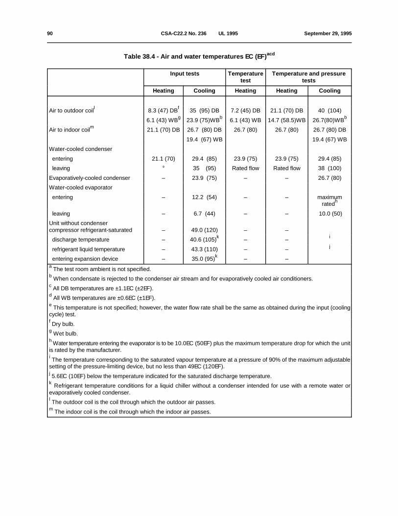
90 CSA-C22.2 No. 236 Ç UL 1995 September 29, 1995
Table 38.4 - Air and water temperatures EC (EF)acd
Input tests Temperature Temperature and pressuretest tests
Heating Cooling Heating Heating Cooling
Air to outdoor coil 8.3 (47) DB 35 (95) DB 7.2 (45) DB 21.1 (70) DB 40 (104)l f
6.1 (43) WB 23.9 (75)WB 6.1 (43) WB 14.7 (58.5)WB 26.7(80)WBg b b
Air to indoor coil 21.1 (70) DB 26.7 (80) DB 26.7 (80) 26.7 (80) 26.7 (80) DBm
19.4 (67) WB 19.4 (67) WB
Water-cooled condenser
entering 21.1 (70) 29.4 (85) 23.9 (75) 23.9 (75) 29.4 (85)
leaving 35 (95) Rated flow Rated flow 38 (100)e
Evaporatively-cooled condenser – 23.9 (75) – – 26.7 (80)
Water-cooled evaporator
entering – 12.2 (54) – – maximumratedh
leaving – 6.7 (44) – – 10.0 (50)
Unit without condenser compressor refrigerant-saturated – 49.0 (120) – –
discharge temperature – 40.6 (105) – – ik
refrigerant liquid temperature – 43.3 (110) – – j
entering expansion device – 35.0 (95) – –k
The test room ambient is not specified.a
When condensate is rejected to the condenser air stream and for evaporatively cooled air conditioners.b
All DB temperatures are ±1.1EC (±2EF).c
All WB temperatures are ±0.6EC (±1EF).d
This temperature is not specified; however, the water flow rate shall be the same as obtained during the input (coolinge
cycle) test.
Dry bulb.f
Wet bulb.g
Water temperature entering the evaporator is to be 10.0EC (50EF) plus the maximum temperature drop for which the unith
is rated by the manufacturer.
The temperature corresponding to the saturated vapour temperature at a pressure of 90% of the maximum adjustablei
setting of the pressure-limiting device, but no less than 49EC (120EF).
5.6EC (10EF) below the temperature indicated for the saturated discharge temperature.j
Refrigerant temperature conditions for a liquid chiller without a condenser intended for use with a remote water ork
evaporatively cooled condenser.
The outdoor coil is the coil through which the outdoor air passes.l
The indoor coil is the coil through which the indoor air passes.m

September 29, 1995 CSA-C22.2 No. 236 Ç UL 1995 91
Table 38.5 – Maximum acceptable temperatures
Materials and components EC EF EC EF
Column 1 Column 2
A. Motors
1. Class A insulation on coil windings of alternating-current motors having aframe diameter of 178 mm (7 in) or less (not including hermetic motor-compressors)ab
(a) In open motors –
Thermocouple or resistance method 102 215 142 287
(b) In totally enclosed motors –
Thermocouple or resistance method 107 224 142 287
2. Class A insulation on coil windings of alternating-current motors having aframe diameter of more than 178 mm ( 7 in) and of direct- current motors(not including hermetic motor-compressors)ab
(a) In open motors –
Thermocouple method 92 197 142 287
Resistance method 102 215 142 287
(b) In totally enclosed motors –
Thermocouple method 97 206 142 287
Resistance method 107 224 142 287
3. Class B insulation on coil windings of alternating-current motors having aframe diameter of 178 mm (7 in) or less (not including hermetic motor-compressors)ab
(a) In open motors –
Thermocouple or resistance method 122 251 152 305
(b) In totally enclosed motors –
Thermocouple or resistance method 127 260 157 314
4. Class B insulation on coil windings of alternating-current motors having aframe diameter of more than 178 mm (7 in) and of direct-current motors(not including hermetic motor-compressors)a,b
(a) In open motors –
Thermocouple method 112 233 142 287
Resistance method 122 251 152 305
(b) In totally enclosed motors –
Thermocouple method 117 242 147 296
Resistance method 127 260 157 314
5. Class F insulation on coil windings of motors having a frame diameter of178 mm (7 in) or less (not including hermetic motor-compressors)ab
(a) In open motors –
Thermocouple or resistance method 147 296 177 350
(b) In totally enclosed motors –
Thermocouple or resistance method 152 305 182 359
(Continued)

92 CSA-C22.2 No. 236 Ç UL 1995 September 29, 1995
Table 38.5 – Maximum acceptable temperatures
Materials and components EC EF EC EF
Column 1 Column 2
6. Class F insulation on coil windings of motors having a frame diameter ofmore than 178 mm (7 in) (not including hermetic motor-compressors)ab
(a) In open motors –
Thermocouple method 137 278 167 332
Resistance method 147 296 177 350
(b) In totally enclosed motors
Thermocouple method 142 287 172 341
Resistance method 152 305 182 359
7. Class H insulation on coil windings of motors having aframe diameter of 178 mm (7 in) or less (not including hermetic motor-compressors)ab
(a) In open motors –
Thermocouple or resistance method 162 323 192 377
(b) In totally enclosed motors –
Thermocouple or resistance method 167 332 197 386
8. Class H insulation on coil windings of motors having aframe diameter of more than 178 mm (7 in) (not including hermetic motor-compressors)ab
(a) In open motors –
Thermocouple method 152 305 182 359
Resistance method 162 323 192 377
(b) In totally enclosed motors –
Thermocouple method 157 314 187 368
Resistance method 167 332 197 386
9. Hermetic motor-compressor enclosure 150 302 150 302c
B. Components
1. Capacitors
Electrolytic type 67 152 (not specified)d
92 197 (not specified)
2. Field wiring 77 170 92 197
3. Relay, solenoid, and other coils withb
(a) Class A insulated windings –
Thermocouple method 92 197 142 287
Resistance method 112 233 152 287
(b) Class B insulated winding –
Thermocoouple method 112 233 142 287
Resistance method 132 269 152 305
(Continued)

September 29, 1995 CSA-C22.2 No. 236 Ç UL 1995 93
Table 38.5 – Maximum acceptable temperatures
Materials and components EC EF EC EF
Column 1 Column 2
(c) Class F insulated winding –
Thermocouple method 137 278 167 332
Resistance method 147 297 172 341
(d) Class H insulated winding –
Thermocouple method 152 305 182 359
Resistance method 162 323 192 377
4. Solid contacts 92 197 117 242
5. Transformer enclosures –
(a) Class 2 transformers 87 188 112 233
(b) Power and ignition transformers 92 197 117 242
6. Fuse bodies 92 197 122 251h
C. Insulated Conductorsf
1. Flexible cords and wires with rubber, thermoplastic, or neoprene insulation 62 143 87 188
D. Electrical Insulation – Generalf
1. Fibre used as electrical insulation on cord bushings 92 305 177 350
2. Phenolic composition used as insulation or as parts where failure will result 152 305 177 350in a hazardous condition
3. Thermoplastic material temperature rating of material
E. General
1. Surfaces of product, discharge plenum, and duct at points of specified 92 197 124 255zero clearance to test enclosure
2. Surfaces of test enclosure where clearance more than zero to combustible 92 197 124 255material is specified
The motor diameter is to be measured in the plane of the laminations of the circle circumscribing the stator frame,a
excluding lugs, boxes, and the like, used solely for motor cooling, mounting, assembly, or connection.
If the coil is inaccessible for mounting thermocouples (for example, a coil immersed in sealing compound) or if the coilb
wrap includes thermal insulation or more than two layers, 0.8 mm (1/32 in) maximum, of cotton, paper, rayon, or the like,the resistance method is to be used. For a thermocouple measured temperature of a coil of an alternating-current motor,other than a hermetic motor compressor, the thermocouple is to be mounted on the integrally applied insulation on theconductor. At a point on the surface of a coil where the temperature is affected by an external source of heat, thetemperature measured by a thermocouple may be (not including hermetic motor compressors):
(1) 5EC (9EF) for Item A1(a) of this Table;
(2) 10EC (18EF) for Item A3(a) of this Table;
(3) 15EC (27EF) for Items A2(a) and B3(a) of this Table;
(Continued)

94 CSA-C22.2 No. 236 Ç UL 1995 July 31, 1998
Table 38.5 (Concluded)
(4) 20EC (36EF) for Items A4(a), B3(b), and B3(c) of this Table; or(5) 30EC (54EF) for Item B3(d) of this Table;more than the indicated maximum, provided that the temperature rise of the coil, as measured by the resistance method,is not more than that specified in this Table. For the exposed surface of the motor-compressor enclosure including the surface of a wrap-around crankcase heaterc
(see Clauses 44.4 and 51.2). For an electrolytic capacitor that is physically integral with or attached to a motor, the temperature on insulating materiald
integral with the capacitor enclosure may be not more than 92EC (197EF) in tests where Column 1 applies. A capacitor may operate at a temperature higher than 92EC (197EF) but not higher than its marked temperature rating.e
The limitations on phenolic composition and on rubber and thermoplastic insulation do not apply to compounds that havef
been investigated and found to be acceptable for higher temperatures than those specified in this Table. See Clauses 46.2 and 46.4.g
Includes both casing and ferrule. However, a temperature not more than 20EC (36EF) higher than the values indicatedh
in this Table is acceptable on the casing (not ferrule) of a Class G, J, T, or L fuse.
Test Voltage
38.6 Unless otherwise specified, products shall be tested at the appropriate potential indicated in Table38.6.
Table 38.6 – Test voltages
Unit rated voltage Test voltagea
110 – 120 120200 – 208 208220 – 240 240254 – 277 277440 – 480 480550 – 600 600
Other Rated Tolerance shall be ±2%.a
Air Flow
38.7 If the conditioned air flow is adjustable, the initial air flow in all heating tests shall be adjusted to deliverthe minimum air quantity (volume per unit time) specified by the manufacturer. For cooling tests, the airflow shall be adjusted to deliver the maximum air quantity specified by the manufacturer. The staticpressure shall be as indicated in Clause 38.11.
38.8 The air quantity across an air-cooled condenser shall be as specified by the manufacturer if the fandrive is adjustable. However, if the fan drive is direct-connected, the air quantity may be that which resultswhen all inherent resistance elements are in place.
38.9 The condenser air system shall be operated to deliver minimum rated air flow at the maximum ratedstatic pressure if an air-cooled condenser is intended to be duct-connected.

July 31, 1998 CSA-C22.2 No. 236 Ç UL 1995 95
38.10 If multispeed or multiple condenser fan motors are employed, and if the speed, or the number ofmotors operating, can be changed automatically by the use of a temperature or pressure-operated controldevice, the electrical input to the motor compressor is to be measured when stabilized conditions areobtained at the maximum condenser inlet air temperature (not exceeding 40EC (104EF), which is just underthe temperature at which the fan speed starts to increase or an additional fan motor starts to run.
Static Pressure
38.11 For units with heating means (supplementary or inherent), the static pressure in the duct system is tobe initially adjusted to the maximum static pressure specified by the manufacturer, or to the static pressureof Table 38.7, whichever is the greater, at the start of the test sequence. For units without heating means, the static pressure in the duct system is to be initially adjusted to theminimum static pressure specified by the manufacturer, or to the static pressure of Table 38.8, whichever isthe smaller, at the start of the test sequence.
38.12 For units without a duct system (free air discharge) the requirements of Clauses 38.11, 38.14, and38.15 are not applicable.
38.13 If filters are factory-provided with the unit, or specified for field installation, they shall be in placeduring all of the tests.
38.14 External static pressure shall be measured by a manometer or pressure transducer. One side of theinstrument shall be connected to the discharge plenum. For units utilizing an inlet duct, the other side of theinstrument shall be connected to the inlet duct. For units without an inlet duct, the other side of theinstrument shall be open to the surrounding atmosphere.
Table 38.7 – Operating conditions ; relation of total static pressure to total heat outputa
Total rated heating, kW Minimum total static pressure, mm (in) water column
0 – 19.99 3.1 (0.12)
20 – 29.99 3.8 (0.15)
30 – 44.99 5.1 (0.2)
45 and over 6.35 (0.25)
For equipment not tested with an air filter, add 2 mm (0.08 in) to the applicable pressure in the Table. For units intendeda
for use with refrigerant coils that are tested without the coils in place, add 1.27 mm (0.05 in) to the applicable pressure.

96 CSA-C22.2 No. 236 Ç UL 1995 September 29, 1995
Table 38.8 – Operating conditions; relation of total static pressure to cooling ratings
Standard cooling rating Minimum total static pressure, mm (in) water column
Btu/h (in thousands) mm of water in of water
0 through 17 1.27 (0.05)
18 through 28 2.54 (0.10)
29 through 42 3.81 (0.15)
43 through 70 5.08 (0.20)
71 through 105 6.35 (0.25)
106 through 140 7.62 (0.30)
141 through 210 8.89 (0.35)
211 through 280 10.16 (0.40)
281 through 350 11.43 (0.45)
38.15 For the connections to the manometer or pressure transducer, a metal tube having an internaldiameter of approximately 6.4 mm (0.25 in) shall be centred at a specified location (see Figure 38.1) andsoldered to the surface of the discharge plenum. Then a hole, 1.0 mm (0.04 in) in diameter, shall be drilledthrough the wall of the discharge plenum at this location; the inner surface of this wall adjacent to the holeshall be smooth and free from irregularities. Connection of these tubes to the manometer or pressuretransducer shall then to be made by means of a suitable length of rubber tubing or the equivalent. Insteadof the above, a static pitot tube or the equivalent may be used.
Unit Setup
38.16 The unit is to be connected to an electrical supply source with wire sized as required for wire rated75EC (167EF) except that, if the product is marked for use with a higher temperature in accordance withClause 37.10, wire of the temperature rating specified in the marking may be used. The supply wires shallbe sized in accordance with Table 2 of the Canadian Electrical Code, Part I, CSA Standard C22.1, andTable 310-16 of the National Electrical Code, ANSI/NFPA No.70-1993. The correction factors from thereferenced tables shall not be considered.
38.17 Adjustable limit controls are to be set at maximum cutout and minimum differential permitted by thecontrol adjusting means.
38.18 For units that include electric resistance heating means, the limit controls used shall be calibratedsamples that have cutout temperatures as close as possible to the nominal setting with the tolerances notexceeding ±2.8EC (5EF) of the nominal cutout temperature.
38.19 For the cooling operation test and temperature operation test (Section 40), an inlet duct is notrequired. For heating tests, an inlet duct is to be connected to the return air opening of the unit (assumingthat the unit is intended to be so applied). The duct is to be the same size as the flanges, if flanges areprovided. If flanges are not provided, the duct is to be the same size as the inlet opening.
38.20 The inlet duct is to be provided with an adjustable restricting means by which the air flow can bereduced. The restriction should be uniform across the duct cross-sectional area, so that the full heating coilsurface will be exposed to the air flow except when the restriction is closed.

September 29, 1995 CSA-C22.2 No. 236 Ç UL 1995 97
38.21 A unit that has provision for the attachment of an outlet duct or plenum is to be fitted as describedbelow for tests in which an outlet duct is specified. The duct is to be the same size as the flanges, if flangesare provided. If flanges are not provided, the duct is to be the same size as the outlet opening.
38.22 A unit that does not include electric heating means is to be fitted with an outlet duct sized to fit thecasing flanges, or openings without flanges, or locations marked for flanges, and arranged to dischargeaway from the return air inlet.
38.23 A unit that includes or has provision for field installation of electric heating means is to be fitted with ametal plenum and an outlet duct in accordance with Figure 38.1.

98 CSA-C22.2 No. 236 Ç UL 1995 September 29, 1995
Figure 38.1 – Warm Air Outlet

July 31, 1998 CSA-C22.2 No. 236 Ç UL 1995 99
Notes to Figure 38.1:
1) The enclosure illustrated represents a plan view for a horizontal discharge unit, and a side view (rotated 90E) for anupflow or downflow unit. The outlet duct of an upflow or downflow unit shall extend at a right angle to the discharge airflow direction, and is to discharge away from the return air inlet.
2) Plenum dimension Y is determined as follows:
a) Horizontal flow unit: Y may be no more than square root of X.
b) Upflow unit: Same as for horizontal flow unit, except that height of unit plus Y may be no more than 2.3 m (7 ft, 6 in)minus specified clearance to combustible material for a unit other than a mobile home unit, or 2.1 m (7 ft) minus thatclearance for a mobile home unit.
3) Downflow unit: Y may be no more than 305 mm (12 in) plus square root of X for a unit other than a manufactured(mobile) home unit, or 25.4 mm (1 in) plus square root of X for a manufactured (mobile) home unit. However, in eithercase, the spacing may be increased if necessary, to obtain the specified clearance to combustible material from the uppersurface of the outlet duct.
4) The thermocouple grid is to consist of nine thermocouples of identical length, wired in parallel to form a grid with athermocouple located centrally in each of nine equal duct areas in a plane perpendicular to the axis of air flow.
5) The outlet duct system shall be provided with means for restricting the air flow.
38.24 Thermostats intended for control of room temperature, outdoor thermostats, or other temperatureregulating controls whose functioning during the normal operation of the equipment may tend to reduce thetemperatures, shall be shunted out of the circuit, except as allowed in Clause 45.7.
Test Enclosure
38.25 The requirements in Clauses 38.26 to 38.29 apply only to a product that includes, or has provisionfor field installation of, electric heating means.
38.26 When zero clearance is specified, an insulating blanket 25.4 mm (1 in) thick and having a density noless than 16 kg/m (1 lb/ft ) shall be wrapped closely around the plenum, outlet duct, and other heated3 3
surfaces.
For units that meet the zero clearance temperature test requirements, clearances greater than zero may bespecified on the unit nameplate.
38.27 For units for which other than zero clearance is specified, a wood test enclosure shall be installed soas to encase the plenum, outlet duct, and heated surfaces of the unit which includes electric heatingmeans.
The wood test enclosure shall consist of 25.4 mm (1 in) nominal thickness wood boards, or 19.1 mm(3/4 in) plywood, with inside surfaces painted flat black, and with all joints sealed. It is to be completelyencased, and shall be spaced from the heated surfaces according to the clearance from combustiblesurfaces specified by the manufacturer.
38.28 If the unit is intended to be installed on a noncombustible floor, the floor of the partial enclosure shallbe of noncombustible material such as stone, brick, or concrete. If the unit is intended to be installed on acombustible floor, the floor of the partial enclosure shall consist of unpainted plywood, 19 mm (3/4 in) thick.

100 CSA-C22.2 No. 236 Ç UL 1995 July 31, 1998
38.29 Temperatures shall be measured on the metal surfaces, if zero clearance is specified. Temperatures shall be measured on the inside surfaces of the wood enclosure, if a clearance of more thanzero is specified.
Instrumentation
38.30 Temperatures shall be measured by thermocouples, except that the change of resistance methodmay be used to measure the temperature of motor windings or of coils. The thermocouples shall consist ofwires not larger than 24 AWG and not smaller than 30 AWG.
38.31 A thermocouple junction shall be securely held in good thermal contact with the surface of thematerial whose temperature is being measured. Adequate thermal contact may be obtained by taping,cementing, brazing, or soldering the couple in place.
38.32 Pressure gauges as applicable shall be attached using minimum lengths of 3.2 mm (1/8 in) outsidediameter tubing.
39 Input test
Circuits–Other than Electric Heaters
39.1 The electrical input shall be measured when stabilized thermal conditions are obtained. Theelectrical input to compressor motors and other electrical loads shall be measured under the followingconditions:
a) load conditions–as specified in Table 38.4 or Clause 38.3, as applicable;
b) voltage–at unit nameplate marked voltage; tolerances as specified in Table 38.6.
Exceptions: This test may be waived, if
1) the rated load amperes marked on the product nameplate is not less than 5 per cent below the inputamperes as measured during the heating, cooling, and temperature operation tests, Sections 40through 43; or
2) the unit is provided with a current-limiting control system.
Electric Heater Circuits
39.2 The input to the electric heater circuits shall be measured when the product is operating under thefollowing conditions:
a) sample–as specified in Clause 38.16. Any inlet temperature between 15.5EC (60EF) and 35EC(95EF) dry bulb is acceptable for this test. (The wet bulb air temperature is not specified.)
b) voltage–as specified in Table 38.6.

July 31, 1998 CSA-C22.2 No. 236 Ç UL 1995 100A
40 Temperature operation test–without any supplementary heating means
40.1 Motor protective devices shall not trip during the test. The maximum temperature measured shall notexceed the values specified in Column 1 of Table 38.5.
40.2 The test arrangement and conditions are to be as follows:
a) voltage–as specified in Table 38.6.

100B CSA-C22.2 No. 236 Ç UL 1995 July 31, 1998
No Text on This Page

September 29, 1995 CSA-C22.2 No. 236 Ç UL 1995 101
b) inlet air conditions–26.7EC (80EF), ±1.1EC (±2EF) DB, wet bulb is not specified.
40.3 The unit is to be operated continuously until temperatures are constant. The electrical input to themotor(s) and other electrical loads are to be measured during the test.
41 Temperature operation tests–with hot water or steam heating
41.1 For a unit employing a hot water coil, the temperature of the entering water is to be the maximum inlettemperature marked on the unit. The rate of flow is to be so adjusted that the temperature of the water atthe outlet is 11EC (20EF) lower than that of the entering water, except that a lower temperature differentialmay be employed if recommended by the manufacturer.
41.2 For a unit employing a steam coil, the pressure of the entering steam is to be the maximum steampressure marked on the unit.
41.3 The temperature of the discharge air shall not exceed 93EC (200EF) during the test.
41.4 Motor protective devices shall not trip during the test. The maximum temperatures measured shallnot exceed the values specified in Column 1 of Table 38.5.
41.5 The test voltage is to be as specified in Table 38.6. The inlet air temperature maintained during thetest shall be 26.7EC (80EF) ±1.1EC (±2EF) dry bulb. Wet bulb temperature is not specified.
41.6 The unit is to be operated continuously until temperatures are constant. The electric input to themotor(s) and other electrical loads are to be measured during the test.
42 Cooling operation test–temperature and pressure
42.1 This test is to be conducted on all units having provision for cooling that employ refrigerant coils forevaporating and condensing. Pressure-limiting devices and motor protective devices shall not trip duringthe test. The maximum temperatures measured shall not exceed the values specified in Column 1 of Table38.5, except that electrical components in an air handling compartment tested with 40EC (104EF) inlet airmay exceed these values by 13.3EC (24EF). The test shall not result in refrigerant leakage or rupture ofparts.
42.2 The test arrangement and conditions are to be as follows:
a) load conditions–as specified in Table 38.4;
b) voltage–as specified in Table 38.6.
During the temperature and pressure test on liquid chillers employing centrifugal motor-compressors, themotor-compressor shall be loaded to its marked rated load current. See Exception in Clause 39.1.
42.3 The unit shall be operated continuously until temperatures are constant and the maximum pressuresare determined. The electrical input to the compressor motor and other electrical loads shall be measuredduring the test.

102 CSA-C22.2 No. 236 Ç UL 1995 September 29, 1995
43 Heating operation test–temperature and pressure
43.1 This test shall be conducted on all units that have provision for refrigerant heating without anysupplementary means for heating (for example, electric heaters, hot water, steam, gas, or oil). During thistest, the maximum temperatures measured shall not exceed the values specified in Column 1 of Table38.5. There shall be no refrigerant leakage or rupture of parts.
43.2 The test arrangement and conditions are to be as follows:
a) load conditions–as specified under "Temperature and pressure tests–heating" of Table 38.4;
b) voltage–as specified in Table 38.6.
After the air flow and static pressure are initially set, the inlet air opening is to be restricted to approximately50 per cent of the opening area. The test shall continue until temperatures are constant, and the maximumpressure has been determined.
Exception: For heat pumps not provided with an indoor fan motor and intended to operate in conjunctionwith an installed furnace, the indoor air quantity is to be adjusted to a value 10 percent less than thespecified minimum value in the manufacturer's instructions.
43.3 With reference to Clause 43.2, if operation is interrupted by a limit control or motor overload protectivedevice, when the inlet air is restricted, the restriction shall be eased slowly until the heat pump operateswithout interruption. The test shall continue until temperatures are constant and the maximum pressurehas been determined.
44 Abnormal temperature and pressure tests–refrigerant heat only
44.1 If the equipment has a pressure-limiting device that is in compliance with Clauses 33.24 to 33.30, thetests described in Clauses 44.2 and 44.3 may be waived.
Indoor Fan Failure and Water Failure
44.2 The unit shall be operated under the conditions of Section 43 until constant temperatures have beenattained. The indoor fan motor shall then be disconnected, and the unit permitted to function as it will untilmaximum temperatures and pressures are attained, or until representative maximum temperatures andpressures are reached under cycling load. The compressor motor overload device and/or the fan motoroverload device may operate during this test. The room ambient shall be approximately 26.7EC (80EF). The test voltage shall be as specified in Table 38.6.
44.3 The unit shall be operated with the water shut off, and also with the water restricted until maximumstabilized temperatures are reached or until representative maximum temperatures are attained undercycling load. If the unit cycles on a motor overload protective device, the test shall continue until themaximum pressure during the protective device operation is obtained. The room ambient shall beapproximately 26.7EC (80EF).
44.4 The equipment tested as specified in Clauses 44.2 and 44.3 is considered to comply if all of thefollowing conditions are met:
a) the refrigerant system does not rupture or develop leaks during the test. The maximum pressurerecorded is to be used to determine the strength of all parts in the equipment;

February 28, 1997 CSA-C22.2 No. 236 Ç UL 1995 103
b) the maximum temperature of the hermetic motor compressor enclosure does not exceed 150EC(302EF);
Exception: An enclosure subjected to discharge gas is not to exceed 200EC (392EF). The equipment shallthen be subjected to the Dielectric Voltage Withstand Test of Section 52.and
c) there is no damage to any electrical components or refrigerant-containing parts.
45 Electric heater tests
General
45.1 The tests in this Section shall be conducted on any unit that employs electric resistance heaters. Fora heat pump the unit shall be operated under the load conditions specified under "Temperaturetest-heating" or "Input test-heating" in Table 38.4. The air temperature rise across the indoor coil of the heatpump shall be measured. This air temperature rise shall be maintained using any heat source during all ofthe subsequent tests involving simultaneous electric resistance heat and refrigerant heat, unless and until,during the abnormal temperature tests, the high pressure switch functions to shut off the refrigeration unit. A higher temperature rise is permitted.
Continuity of Operation–Simultaneous Electric Resistance Heat and Refrigerant Heat
45.2 This test shall be conducted on any heat pump that includes electric heating means. The unit shalloperate continuously without opening any limit control or overload protective device.
45.3 The test arrangement and conditions are to be as follows:
a) load conditions–as specified under "Temperature test-heating" in Table 38.4;
b) voltage–as specified in Table 38.6.
45.4 The product shall be placed in heating operation with all electric heaters energized. There shall beno inlet air restriction except as inherent in the device, with air filters in place.
45.5 The test shall continue until the outlet air and surface temperatures have stabilized.
45.6 A temperature- or pressure-limiting device, or a motor overload protective device, shall not openduring the test.
45.7 An air-to-air heat pump, so designed that all supplementary heaters cannot be energized if operatedat the outdoor temperature specified in Table 38.4, may be tested at the maximum outdoor air temperaturethat permits the heaters to be energized. Any control that controls the operation of electric heaters shallcomply with Clause 30.12.
Continuity of Operation–Electric Resistance Heat Only
45.8 This test shall be conducted on any unit that can have only the electric resistance heaters operatewithout any other heating means, except hot water or steam heating. The unit shall be operated asspecified in Clause 45.2, except that any refrigeration unit shall be inoperative and the ambient temperatureis not specified. The voltage is as specified in Table 38.6. If hot water or steam heating
104 CSA-C22.2 No. 236 Ç UL 1995 July 31, 1998
can be simultaneously energized with the electric heaters, this additional heating means shall be operatingduring the test. See Section 41.
Limit Control Cutout Test–Simultaneous Electric Resistance Heat and Refrigerant Heat
45.9 A limit control, when adjusted to the maximum setting allowed by a fixed stop, shall prevent a unitfrom delivering air at a temperature exceeding 93.3EC (200EF).
45.10 The test arrangement and conditions are as described for the continuity of operation test, Clause45.2. The unit is to be operated as described in that clause until the outlet air temperature is constant.
45.11 The inlet opening is to be slowly and uniformly restricted at the rate indicated in Clause 45.13, withno other readjustment of the system, until a limit control opens, at which point the outlet air temperature isto be measured.
45.12 If the heat pump and/or heater circuits are not fully deenergized by the first limit control operation,the test shall be continued by further restricting the inlet air until either all limit controls trip or the outlet airtemperature stabilizes.
45.13 The outlet air temperature rise caused by the restriction of the air inlet opening shall beapproximately 1.1EC/min (2EF/min). If more than 10 min is required before the first limit control opens, thespecified rate of restriction need only apply to the final 10 min period prior to functioning of that limit control.
Limit Control Cutout Test–Electric Resistance Heat Only
45.14 The requirements of Clauses 45.9 to 45.13 shall also apply to equipment with any refrigeration unitinoperative with the outdoor temperature not specified.
Heating Operation Test–Unit with Electric Resistance Heaters
45.15 The requirements of this Clause shall be applied to equipment operating in the electric heat onlymode, simultaneous electric resistance heat with hot water or steam mode, or in the simultaneous electricresistance heat and refrigerant heat mode of operation.
45.16 This test shall be conducted immediately following the Fan Delay Test, Section 48, if performed, andthe Limit Control Cutout Tests, Clauses 45.9 to 45.14.
45.17 The test arrangement and conditions are the same as for the limit control cutout tests, except thatthe limit controls shall be shunted out of the circuit. The inlet air restriction shall be eased until the outputair temperature is 3EC (5.4EF) less than the outlet air temperature measured at the time of operation of thefirst limit control during the Limit Control Cutout Test.
45.18 The unit shall be operated continuously until constant temperatures and maximum pressures aredetermined. The electrical input shall be measured at intervals during the test.
45.19 The maximum temperatures measured shall not exceed the values specified in Column 1 ofTable 38.5.
45.20 The test shall not result in refrigerant leakage or in rupture of parts. The maximum pressure shall berecorded as a basis for the strength test requirements.

July 31, 1998 CSA-C22.2 No. 236 Ç UL 1995 105
46 Abnormal temperature and pressure tests
General
46.1 These tests shall be conducted on any unit with supplementary heating means and all those specifiedin Table 38.2.
46.2 The tests described in this Section shall not result in refrigerant leakage or rupture of parts. Themaximum pressure shall be recorded as a basis for the strength test requirement. A unit employing apressure-limiting device complying with clause 33.27 as applicable is considered to comply with the highside pressure requirment.
46.3 For units intended to be connected to a duct system, the maximum temperatures measured duringthe tests described in this Section shall not exceed
a) the value specified in Column 2 of Table 38.5 during 1 h after the first operation of a limit control ormotor overload protective device; and
b) the value specified in Column 1 of Table 38.5 thereafter; except that a motor may attain thetemperature specified in Column 2 during any part of the test.
46.4 For units without a duct system (free air discharge), the requirements of Clause 46.3 are notapplicable. See Clause 46.5.
46.5 During the tests described in this Section there shall be no
a) emission of flame or molten metal; or
b) risk of electric shock hazard; or
c) glowing or flaming of the felt, cheesecloth, or drape (for units without a duct system, free airdischarge only).
46.6 The test arrangement and conditions are unchanged from the continuity of operation test for the typeof unit under test. The unit shall be operated to constant outlet air temperature, with the bypass removedfrom the limit controls.
46.7 Unless it is a required backup control, a manually resettable supplementary control that is a limitcontrol may function during the tests specified in Clauses 46.11 to 46.16.
46.8 Units with multiple voltage ratings shall be tested as follows:
a) All abnormal tests shall be conducted at the voltage that results in the highest limit cutouttemperature. See Clauses 45.9 to 45.14.
b) The abnormal test that results in the highest temperature shall be repeated at the other voltages. The remaining abnormal tests may be waived on the basis of the results.
46.9 For units without a duct system (free air discharge), when tested per Clauses 46.11 to 46.13, a layerof cheesecloth shall be placed over the outlet air opening. During the blocked outlet test, the cheeseclothshall be covered with a 25 mm (1 in) thick felt pad.

106 CSA-C22.2 No. 236 Ç UL 1995 July 31, 1998
46.10 The felt mentioned in Clause 46.9 shall be standard weight, animal hair, punched felt with centrereinforcement consisting of burlap having a mass of 170 g/m (5 oz/sq. yd). Felt 25 mm (1 in) thick has a2
mass of 3.56 ± 0.51 kg/m (105 ± 15 oz/sq. yd). The cloth shall be bleached cheesecloth, 914 mm (36 in)2
wide, approximately 28 to 30 m/kg mass (14 to 15 yd/lb, and having for any 25.4 × 25.4 mm (1 × 1 in)square, 32 threads in one direction and 28 threads in the other.
Restricted Inlet
46.11 The test shall be conducted under the same conditions as in the continuity of operation test for thetype of unit under test and may be a continuation of the limit control cutout test. The inlet is to be uniformlyrestricted at such a rate that the outlet air temperature increases approximately 1.1EC (2EF) per min, butnot faster, until operation is interrupted by a temperature limit control. The equipment shall be permitted tofunction without any further adjustment until temperatures become stabilized; the increase in restriction isthen resumed until a second temperature limit control (if any) functions. Conditions are again allowed tobecome stable, and the restriction is then resumed. This procedure is continued until the resultingtemperatures and pressures are the maximum that occur with any amount of restriction.
Fan Failure
46.12 The unit is restored to operation temperatures, as in the continuity of operation test. The blowermotor is deenergized. The assembly shall be permitted to function as it will until maximum temperaturesare reached under stable or cycling conditions.
Blocked Outlet
46.13 The equipment shall be allowed to resume normal temperatures as in the continuity of operationtest, with the blower motor operating. The air outlet shall then be blocked completely, and operationcontinued until the limit control functions to interrupt the heater element circuit. The system shall then bepermitted to function without any further adjustment until maximum stabilized temperatures are reached oruntil representative maximum temperatures are attained under cycling load.
46.14 This test is not to be conducted on any unit without a duct system (free air discharge) with any airdischarge openings located more than 1.22 m (4 ft) above the floor level when the unit is installed asintended.
Curtain Drape
46.15 This test is not to be conducted on a ceiling-mounted, or on a top or bottom discharge wall or floormounted unit without a duct system (free air discharge).
This test may be waived if during the continuity of operation test the curtain drape is blown away from thedischarge openings of the unit.
46.16 The upper edge of a simulated curtain, a minimum of 0.9 m (3 ft) high vertically and a minimum of2.4 m (8 ft) long horizontally, is to be continuously attached to a vertical wall above the unit. The curtain isto consist of 8 oz white duck plus an overlay of cheesecloth as described in Clause 46.10 on the side facingthe heater, and shall be hung loosely in folds so that a 2.4 m (8 ft) length covers a 1.8 m (6 ft) length of theunit, completely blocking the air discharge openings. The bottom edge of the curtain shall be located sothat it will barely touch the floor. During the test, the curtain is to be draped to conform as closely aspossible to the contour of the surface of the unit.

September 29, 1995 CSA-C22.2 No. 236 Ç UL 1995 107
47 Backup Protection Tests
General
47.1 The tests described in this clause shall be conducted on a product provided with, or having provisionfor field addition of, electric heaters and which is provided with a backup protective device (seeClause 30.15). These tests do not apply to units without a duct system (free air discharge). If the unit is aheat pump, the unit shall operate the electric heaters simultaneous with the refrigerant heat.
47.2 When tested in accordance with this clause, the temperature at the points mentioned in Clause 47.3shall not exceed 100EC (212EF) except that the temperature shall not exceed 130EC (266EF) during the30 min period following the initial imposition of the test condition. The temperature following the functioningof one or more of the manually resettable or nonresettable limit controls or thermal cutoffs may be no morethan 175EC (347EF); however, at the end of the 30 min period following the functioning of the first control orcutoff, the temperature shall not exceed 100EC (212EF).
47.3 The temperature limit mentioned in Clause 47.2 applies to the metal duct and the product itself,where suitable for zero clearance installation, and the inside surface of the wooden test enclosure, of anyproduct employing electric heaters.
47.4 The test arrangement and conditions are unchanged from those described in the Abnormaltemperature and pressure tests, Clause 46. The product shall be operated as described in the continuity ofoperation tests until the outlet air temperature is constant, with the automatically reset temperature-limitingcontrol of the electric heaters bypassed.
47.5 A pressure-limiting device or other control may operate to deenergize the compressor motor duringthe tests described in Clauses 47.7 to 47.10. If a manually reset pressure or temperature-limiting devicealso deenergizes the electric heater circuits, the latter function shall be
a) bypassed if the device controls the heater through a contactor or equivalent control that alsooperates in the normal temperature-regulating circuit of the heater; and
b) allowed to control the heater if such control is accomplished through a backup contactor.
47.6 Clause 46.8 shall apply for multiple voltage rated units.
Restricted Inlet
47.7 This test shall be conducted as described in Clause 46.11, except that the rate of restriction of theinlet duct is to be such that the opening is totally blocked at the end of 30 min.
47.8 If a manually reset pressure- or temperature-limiting device that is not bypassed for heater control, asindicated in Clause 46.6, operates to deenergize the product and the electric heaters, the tests indicated inClauses 47.9 and 47.10 may be waived.
Fan Failure
47.9 This test shall be performed in accordance with Clause 46.12.
Blocked Outlet
47.10 This test shall be performed in accordance with Clause 46.13.

108 CSA-C22.2 No. 236 Ç UL 1995 September 29, 1995
48 Fan delay test–duct-connected downflow and horizontal units
48.1 During the normal operation of horizontal or downflow equipment provided with a fan delay control,starting with the equipment at room temperature, the fan control shall operate to prevent the air in the inletand on the air filter, if provided, from attaining a temperature higher than 90EC (194EF). A limit control,thermal cutoff, or motor overload device shall not open before the fan control functions.
48.2 For downflow equipment, a duct having a cross-section the same size as the inlet air opening of theunit shall be attached to the return inlet air opening, and extended vertically, using a 90E elbow if the unithas only a side inlet air opening, to a distance of 2.3 m (7-1/2 ft) above the base of the unit. For horizontalequipment, a duct having a cross-section the same as the inlet air opening in the unit shall be attached tothe air inlet, and extended vertically by means of a 90E elbow for a distance of 1.8 m (6 ft) above the top ofthe return air opening. The sample is to be arranged to operate against an external static pressure asspecified in Clause 38.11. Any fan or limit control, if adjustable, shall be adjusted to the maximumtemperature setting allowed by a fixed stop and minimum differential.
48.3 The temperature of the air in the inlet duct shall be measured by means of three thermocoupleslocated in the plane of the return air (inlet air) opening of the unit. For a downflow unit, the thermocouplesshall be on the horizontal centre line of the return air opening. For a horizontal unit, the thermocouplesshall be on a horizontal line 1/3 of the distance below the top of the return air opening. One thermocoupleis to be located 25.4 mm (1 in) from one side of the opening, one at the centre, and the other 25.4 mm(1 in) from the opposite side of the opening. None of the three thermocouples shall indicate a temperaturehigher than 90EC (194EF) prior to the operation of the fan control.
48.4 The conditions shall be as described in the continuity of operation test, see Clause 45.3 or 45.8, asapplicable.
49 Control System Failure Test
49.1 The test described in Clauses 49.2 and 49.3 shall be conducted on any heat pump that is notprovided with an indoor fan motor assembly (and hence is intended to be used with the fan motor assemblyof an installed air handling unit).
Exception: a unit provided with a hazardous voltage interlocking circuit to prevent simultaneous operation ofthe heat pump and installed air handling unit need not be tested.
49.2 The heat pump shall be operated as described in the heating operation test without supplementaryelectric heaters, Section 43, except that the inlet air temperature to the heat pump indoor coil shall beadjusted to 71.1EC (160EF). The indoor air quantity shall be adjusted to a value 10 percent less than thespecified minimum value in the manufacturer's instructions.
The heat pump is to be operated to establish that the control specified in Clause 26.15 stops operation ofthe compressor motor before the compressor motor overload protective device operates. The heat pumpshall be operated to constant temperatures as described in Section 43, Heating Operation Test–Temperature and Pressure.
Note: The motor overload protective device may operate if the device is in a manual reset circuit thatprevents automatic restarting of the compressor motor.
49.3 The maximum temperatures measured shall not exceed the values specified in Column 1 of Table38.5. The test is not to result in refrigerant leakage or rupture of parts. The maximum pressure shall berecorded as a basis for the strength test requirements.
July 31, 1998 CSA-C22.2 No. 236 Ç UL 1995 109
50 Fan motor failure test
50.1 If the equipment has a pressure-limiting device that is in compliance with Clauses 33.24 to 33.30, thetest described in Clause 50.2 may be waived.
50.2 The unit shall be operated under the conditions of Section 42 except the room ambient is to beapproximately 26.7EC (80EF), until temperatures and pressures become constant. The outdoor fan motorshall then be locked or deenergized, and the unit allowed to operate until maximum stabilized temperaturesand pressures are reached or until representative maximum temperatures and pressures are attainedunder cycling load. The compressor motor overload device and/or the fan motor overload device mayoperate during this test. The unit shall comply with Clause 51.2.
51 Condenser water failure test
51.1 For those units having water-cooled refrigerant heat exchangers, the unit, while operating in thecooling mode, shall be operated as in Section 42 until temperatures and pressures become constant,whereupon the water shall be shut off or the condensing water restricted, until the maximum stabilizedtemperatures and pressures are reached or until they are attained under cycling load. If the unit cycles ona motor overload protective device, the test shall be continued until the maximum pressure during theprotective device operation is obtained. The room ambient temperature is to be approximately 26.7EC(80EF).
51.2 The equipment is considered to comply, if all of the following conditions are met:
a) the refrigerant system does not rupture or develop leaks during the test. The maximum pressurerecorded shall be used to determine the strength of all parts in the equipment. A unit employing apressure-limiting device complying with Clause 33.27, as applicable, is considered to comply with thehigh-side pressure requirement; and
b) the maximum temperature of the hermetic compressor motor enclosure does not exceed 150EC(302EF);
Exception: An enclosure subjected to discharge gas shall not exceed 200EC (392EF). The equipmentshall then be subjected to the Dielectric Voltage Withstand Test of Section 52.
and
c) there has been no damage to the electrical components and refrigerant-containing parts.
52 Dielectric voltage–withstand test
52.1 The equipment shall withstand without breakdown the following:
a) a 60 Hz potential, as specified below, applied between live parts of hazardous voltage circuits, anddead (grounded) metal parts, for a period of 1 min. For the test, the unit may be in a heated orunheated condition.
1) 1000 V for units rated 250 V or less, and which include a motor rated at less than 1/2 hp.

110 CSA-C22.2 No. 236 Ç UL 1995 September 29, 1995
2) 1000 V plus twice rated voltage for units rated more than 250 V or which include a motor rated1/2 hp or larger.
For units employing extra-low-voltage circuits, the test shall be conducted with this circuit connected to thecabinet, chassis, or other dead (grounded) metal parts, so that the potential that is applied between the livehazardous voltage parts and dead (grounded) metal parts will simultaneously be applied between the livehazardous voltage parts and the extra-low-voltage circuits.
52.2 The test equipment used to determine compliance with Clause 52.1 shall include a transformerhaving an essentially sinusoidal output with a rating sufficient to maintain the required test potential. It is alsoto include an audible or visual indication of breakdown.
52.3 If the output of the test-equipment transformer is less than 500 VA, the equipment shall include avoltmeter in the output circuit to directly indicate the test potential. If the output of the test equipmenttransformer is 500 VA or larger, the test potential may be indicated by an acceptable voltmeter in theprimary circuit or in a tertiary winding circuit, by a selector switch marked to indicate the test potential, or bya marking in a readily visible location to indicate the test potential on equipment having a singletest-potential output. When marking is used without an indicating voltmeter, the equipment shall include ameans, such as a power-on lamp, to indicate that the manual reset switch has been reset following atripout.
53 Condensate drain blockage test
53.1 The equipment shall be installed as intended, with the indoor fan motor energized. All condensatedrain lines except overflow lines shall be blocked, and water added to the drain pan at a rate of not lessthan 500 mL (1 pint) per minute for each 472 L/s (1000 CFM) of air flow, until water overflows onto thefloor.
During this test, water shall not impinge on uninsulated hazardous voltage parts and extra-low-voltagesafety circuits, and shall not be retained within the enclosure for electrical parts or wiring.
A motor winding may be wetted; however, it shall be subjected to the Dielectric voltage-withstand test,Clause 52.
53.2 If the drain pan is located below all electrical parts, the test described in Clause 53.1 may be waived.
54 Loading Test
54.1 A substantially horizontal plane on the top of equipment shall be capable of sustaining a static load of91 kg (200 lbs), applied in a vertical direction, in the most unfavourable location, over an area of 152 mm(6 in) diameter. This load shall not result in:
a) a deflection that causes the structure to contact a moving part, and
b) a permanent deformation of the structure, so as not to comply with Clause 11.2, and
The structure shall comply with the requirements of this Standard following the loading test in the asreceived condition.
Polymeric cabinets and structural parts shall comply with the requirements of this Standard following theloading test in the as received condition.
September 29, 1995 CSA-C22.2 No. 236 Ç UL 1995 111
54.2 Guarding shall have sufficient strength to withstand a force of 111 N (25 lbs) applied anywhere in adirection normal to the surface, by the end of a rod 38.1 mm (1.5 in) in diameter. The application of thisforce shall not result in deflection, which causes the guarding to contact a moving part, and shall not resultin a permanent deformation of the guarding, so as not to comply with Clause 11.2.
55 Limited short-circuit test
55.1 Devices and conductors, as referenced in Clauses 20.15, 23.17, and Exception 2 of Clause 31.5,shall withstand short-circuit and ground-fault conditions when protected by either a device that is suitable forbranch-circuit protection and located in the product, or a branch-circuit protective device of the type andrating specified in Clause 23.17. There shall be no damage to conductors or their terminations, no ignitionof cheesecloth surrounding the enclosure housing the components under test, and no arc over betweenhazardous voltage and extra-low-voltage circuits.
55.2 Each device and each conductor shall be connected in a circuit having a capacity based on the ratedcurrent and voltage of the product; see Table 55.1. The product rated current shall be determined byadding the rated motor currents and the other rated currents. The circuit capacity shall be measuredwithout the devices or conductors in the circuit.
55.3 Three samples of each component under test shall be subjected to each test condition, and a newprotective device shall be used for each test. Consideration is to be given to both short-circuit andground-fault conditions.

112 CSA-C22.2 No. 236 Ç UL 1995 September 29, 1995
Table 55.1 - Limited short-circuit test currents
Product ratings, A
Single phase Circuit capacity,
110 –120 V 200 – 208 V 220 – 240 V 254 – 277 V A
9.8 or less 5.4 or less 4.9 or less – 200
9.9 – 16.0 5.5 – 8.8 5.0 – 8.0 6.65 or less 1000
16.1 – 34.0 8.9 – 18.6 8.1 – 17.0 – 2000
34.1 – 80.0 18.7 – 44.0 17.1 – 40.0 – 3500
Over 80.0 Over 44.0 Over 40.0 Over 6.65 5000
3 phase Circuit capacity,
200 – 208 V 220 – 240 V 440 – 480 V 550 – 600 V A
2.12 or less 2.0 or less – – 200
2.13 – 3.7 2.1 – 3.5 1.8 or less 1.4 or less 1000
3.8 – 9.5 3.6 – 9.0 – – 2000
9.6 – 23.3 9.1 – 22.0 – – 3500
Over 23.3 Over 22.0 Over 1.8 Over 1.4 5000

September 29, 1995 CSA-C22.2 No. 236 Ç UL 1995 113
56 Transformer–burnout test
56.1 There shall be no emission of flame or molten metal from the product enclosure or emission ofsmoke in an indoor air handling compartment, when a transformer having a hazardous voltage primary isoperated under the conditions described in Clauses 56.2 and 56.3.
This test does not apply to a transformer having a hazardous voltage primary that is provided with thermaloverload protection of other than the nonrenewable thermal cutoff type (see Clause 27.4), or that isprotected by an overcurrent device in accordance with the requirements of Clause 27.6.
56.2 Three samples of the transformer shall be operated continuously at the normal test voltage indicatedin Table 38.6 and rated frequency with the enclosure grounded. The test ambient temperature shall be26.7EC (80EF), and operation shall be continued until constant temperature is indicated by a thermocoupleon the enclosure or until burnout occurs. The circuit on which the transformer is tested shall be protectedby fuses rated not less than that required for the product.
56.3 The load connected to the output terminals shall be the highest of the following, and shall bereadjusted to the specified value after 2 min of operation, if necessary, with no further readjustment duringthe test:
a) a resistance load to provide a current equal to three times the full rated transformer secondarycurrent; or
b) if the transformer supplies a motor with or without additional loads, a resistance load to provide acurrent equal to the motor locked rotor current plus any additional load; or
c) if the transformer supplies an inductive load (other than a motor) such as the coils of relays,solenoids, and the like, a resistance load to provide a current equal to the sum of such loads with thearmature of the largest blocked open.
The test may be conducted with the output terminals short-circuited, if this results in less than three timesrated secondary current.
57 Transformer–overload test
57.1 This test applies to a transformer having a hazardous voltage primary provided with thermal protectionof other than the nonrenewable thermal cutoff type. See Clause 27.4.
57.2 Temperatures of a thermally protected transformer having a hazardous voltage primary, measuredon the surface of the windings, shall not exceed the insulation temperature rating when the transformer istested as indicated in Clauses 57.3 and 57.4. Insulation temperature rating is defined as the rating for theclass of insulation.
57.3 A variable resistance load shall be connected to the output terminals, and the transformer operatedcontinuously at the normal test voltage indicated in Table 38.6. If the protective device controls a switchingdevice that, in turn, interrupts primary current to the transformer, the switching device is to be in the circuit. The test ambient temperature is to be approximately 26.7EC (80EF). The resistance load is to be adjustedso that the transformer winding is brought to a stabilized temperature of approximately 10EC (18EF) belowits insulation rating. The load is then to be gradually increased until operation of the protector occurs.
114 CSA-C22.2 No. 236 Ç UL 1995 September 29, 1995
57.4 Three samples of the transformer protector combination shall be tested. Average temperatures ofthe samples shall not exceed the winding insulation rating and the temperature of any one sample shall notexceed the insulation rating by more than 5EC (9EF).
57.5 The transformer shall comply with the dielectric voltage-withstand test, Section 52, following theabove test.
58 Rain test
58.1 The rain test apparatus shall consist of three spray heads mounted in a water supply rack as shown inFigure 58.1. The spray heads shall be constructed in accordance with Figure 58.2. The product shall bebrought into the focal area of the three spray heads in such position, and under such conditions, that thegreatest quantity of water will enter the product.

September 29, 1995 CSA-C22.2 No. 236 Ç UL 1995 115
Figure 58.1 – Rain test apparatus
Item mm inch
A 710 28
B 1400 55
C 55 2.25
D 230 9
E 75 3

116 CSA-C22.2 No. 236 Ç UL 1995 September 29, 1995
Figure 58.2 – Rain Test Spray Head
Item inch mm Item inch mm
A 1-7/32 31.0 N 1/32 0.80B 7/16 11.0 P .575 14.61C 9/16 14.0 .576 14.53D .578 14.68 Q .453 11.51
.580 14.73 .454 11.53E 1/64 0.40 R 1/4 6.35F c c S 1/32 0.80G .06 1.52 T (No. 35) 2.80b
H (No. 9) 5.0 U (No. 40) 2.50b b
J 23/32 18.3 V 5/8 16.0K 5/32 3.97 W 0.06 1.52L 1/4 6.35M 3/32 2.38
Nylon Rain-test spray heads are available from Underwriters Laboratoriesa
ANSI B94.11M Drill Sizeb
Optional – To serve as a wrench grip.c
July 31, 1998 CSA-C22.2 No. 236 Ç UL 1995 117
58.2 The spray shall be directed, at an angle of 45E to the vertical, towards the louvres or other openings closest to liveparts. Water pressure shall be maintained at 34.5 kPa (5 psig) at each spray head.
58.3 The equipment shall be operated so that electrical components are energized, and the product is tested under theintended conditions of use judged most likely to cause the entrance of water into or onto electrical components. It maybe necessary to operate the unit under various modes of operation or to deenergize the product, if more adverseconditions could result. In any case, each exposure shall be for 1 h.
58.4 Openings intended for field conduit connection are to be provided with such connections, with the outer endsealed, but with pipe thread compound at the connection. Openings intended for the entry of conductors for Class 2wiring are not to be sealed.
58.5 After the final exposure to the rain, the complete product shall be subjected to the Dielectric Voltage-WithstandTest, Section 52.
58.6 When multiple exposures to rain are necessary, the dielectric-withstand test shall be repeated in the wet condition ifdrying could occur between exposures.
58.7 Water shall not enter enclosures above the lowest electrical component other than insulated wire. Uninsulatedhazardous voltage parts and extra-low-voltage safety circuits shall not be wetted. There shall be no accumulation ofwater within the enclosures of electrical parts.
Exceptions:
1) Water may enter an enclosure above the lowest electrical component, if the point of entrance is not in proximity tolive parts, and if live parts except insulated wire are not wetted.
2) A motor winding may be wetted if the motor complies with the Dielectric Voltage-Withstand Test of Section 52.
59 Accelerated aging tests
Gaskets
59.1 Rubber or neoprene compounds, except foamed materials, used for gaskets to seal electrical enclosures ofoutdoor equipment, shall have physical properties as indicated in Table 59.1 before and after accelerated aging underthe conditions indicated in Table 59.2.
59.2 Foamed neoprene or rubber compounds forming gaskets to seal an electrical enclosure of outdoor equipmentshall not harden or otherwise deteriorate to a degree that will affect their sealing properties after accelerated aging underthe conditions indicated in Table 59.2.
59.3 Thermoplastic materials forming gaskets to seal an electrical enclosure of outdoor equipment shall not deform,melt, or otherwise deteriorate to a degree that will affect their sealing properties after accelerated aging under theconditions indicated in Table 59.2. Solid polyvinyl chloride gasket material shall have physical properties as indicated inTable 59.1 before and after the accelerated aging.

118 CSA-C22.2 No. 236 Ç UL 1995 July 31, 1998
59.4 Gaskets of materials other than those mentioned in Clauses 59.1 to 59.3 shall be nonabsorptive, and shall provideequivalent resistance to aging and temperatures.
The temperatures indicated in Table 59.2 correspond to the maximum temperatures measured on the gasket during thetemperature and pressure tests.
Table 59.1 - Physical properties for gaskets
Neoprene or rubber Polyvinyl chloride materialscompound
Before test After test Before test After test
Recovery–Maximum set when 25.4 mm (1 in) 6.4 mm (1/4 in) – Not specifiedgauge marks are stretched to 63.5 mm (2-1/2in), held for 2 min and measured 2 min afterrelease
Elongation–Minimum increase in distance 250% 65% of 250% 75% of originalbetween 25.4 mm (1 in) gauge marks at break original
25.4–88.9 mm 25.4–88.9 mm
(1–3-1/2 in) (1–3-1/2 in)
Tensile strength–Minimum force at breaking 5.86 MPa (850 psi) 75% of 8.27 MPa 90% of originalpoint original
(1200 psi)

July 31, 1998 CSA-C22.2 No. 236 Ç UL 1995 119
Table 59.2 - Accelerated aging conditions for gaskets
Measured temperature EC (EF) Material Test program
60 (140) Rubber or neoprene 4 days at 70EC (158EF) in an oxygenbomb at 2.07 MPa (300 psig)
60 (140) Thermoplastic 7 days in an air-circulating oven at 87EC(189EF)
75 (167) Rubber or neoprene 7 days at 80EC (176EF) in an oxygenbomb at 2.07 MPa (300 psig)
75 (167) Thermoplastic 10 days in an air-circulating oven at100EC (212EF)
80 (176) Rubber, neoprene, or thermoplastic 7 days in an air-circulating oven at113EC (235.4EF)
90 (194) Rubber or neoprene 10 days in an air-circulating oven at121EC (249.8EF)
90 (194) Thermoplastic 7 days at 121EC (249.8EF) or 60 days at97EC (206.6EF) in an air-circulating oven
105 (221) Rubber, neoprene, or thermoplastic 7 days in an air-circulating oven at136EC (276.8EF)
Polymeric Materials
59.5 Polymeric material specimens used for cabinets and structural parts shall be conditioned as indicated in Table59.3. The specimens shall then be subjected to the flame/burning tests specified for the material (see Clause 5.9.1) inaccordance with the Standard Evaluation of Properties of Polymeric Materials, CAN/CSA-C22.2 No. 0.17 and Test forFlammability of Plastic Materials for Parts in Devices and Appliances, UL 94, and the following additional tests inaccordance with the Standard Evaluation of Properties of Polymeric Materials, CAN/CSA-C22.2 No. 0.17 andPolymeric Materials-Short Term Property Evaluations, UL 746A; as applicable:
a) tensile strength,
b) flexural strength,
c) izod impact,
d) tensile impact.
Exception: Polymeric material specimens that already have a thermal index rating equal to or greater than that indicatedin Table 59.3 under the normal operating temperature column in accordance with the Standard for Polymeric Materials– Long Term Property Evaluations, UL 746B, and the Standard for Evaluation of Properties of Polymeric Materials,CAN/CSA-C22.2 No. 0.17, are considered to be in compliance with the requirements in Clause 59.5 and need not beretested.

120 CSA-C22.2 No. 236 Ç UL 1995 September 29, 1995
Table 59.3 – Accelerated aging conditions for polymeric materials
Intended use Normal operating Oven aging Conditiona
temperature EC (EF)b
Temperature EC (EF) Time, h
Cabinet (Indoor only) 65 (149) 90 (194) 168
Cabinet 75 (167) 90 (194) 1440
Cabinet 85 (185) 95 (203) 1440
Cabinet 95 (203) 105 (221) 1440
Cabinet 100 (212) 121 (250) 1440
Structural Parts 50 (122) 75 (167) 1440
Structural Parts 75 (167) 100 (212) 1440
Structural Parts 100 (212) 121 (250) 1440
If the same polymeric material is used for both a cabinet and a structural part, it is to be subjected to the oven aginga
condition shown for a cabinet. The oven aging condition shall be the higher of the values shown for either the cabinet orstructural part but not less than that for a normal operating temperature of 75EC (167EF).
Normal operating temperature shall be determined by Tables 38.1 and 38.2 as applicable. If this temperature is betweenb
two values, the higher of these two values shall be used in determining the oven aging condition.
60 Impact test
60.1 Cabinets, structural parts, and enclosures shall comply with the requirements of this Standard following the impacttests.
60.2 These tests shall be applicable to polymeric materials used as a cabinet, structural part, or an enclosure. Thesepolymeric materials shall be tested for strength in locations judged most likely to fail under impact on samples in the asreceived condition. 60.3 A cabinet, structural part or an outer enclosure shall withstand an impact of 6.8 J (5 ft-lb).
Exception: Cabinets of indoor units intended to guard against moving parts shall withstand an impact of 2 J (1.5 ft-lb).
60.4 An internal structural part or an internal enclosure shall withstand an impact of 2 J (1.5 ft-lb).
60.5 With reference to Clauses 60.3 and 60.4, the application of an impact from a steel ball, 51mm (2in) in diameter andweighing 0.53 kg (1.2 lb) shall be applied. This steel ball shall be suspended by a cord and allowed to swing as apendulum or allowed to fall freely from a height of 1290 mm (50.8in) for a 6.8 J (5ft-lb) impact and a height of 380 mm(15 in) for a 2 J (1.5 ft-lb) impact.
60.6 The steel ball shall not impact the surface more than once in the same location.

July 31, 1998 CSA-C22.2 No. 236 Ç UL 1995 121
60.7 Equipment intended for outdoor use shall comply with the resistance to impact test at minus 35 ± 2EC (minus 31EF± 3.6EF) in Standards Evaluation of Properties of Polymeric Materials, CAN/CSA-C22.2 No. 0.17 and PolymericMaterials-Use in Electrical Equipment Evaluation, UL 746C.
61 Strength tests
61.1 These tests shall be applicable to those refrigerant-containing parts and hot water and steam coils that are requiredto comply with the strength requirements specified in Clause 33.
Exception: Pressure-actuated refrigeration controllers and crankshaft seals are not required to meet the requirements ofSection 61.
61.2 Two samples of each refrigerant-containing part shall be tested except that only one sample of the following needbe tested on liquid chillers employing centrifugal motor compressors, motor-compressor enclosure, volutes, cross-overpipe, condenser and evaporator, and the equivalent.
61.3 The test samples shall be filled with any inert liquid, such as water, to exclude air, and shall be connected in ahydraulic pump system. The pressure shall be raised gradually until the required pressure is reached, and shall bemaintained for 1 min.
61.4 The test pressure required shall be computed in accordance with Clauses 33.3 and 33.6.
61.5 Parts shall be considered to comply with the requirement if they do not burst or leak, except that leakage atgaskets shall not be considered a failure if the leakage occurs at a pressure greater than 40 per cent of the required testpressure.
61.6 With reference to Clauses 61.1 to 61.5, sections of the refrigerant system constructed of continuous tubing, or oflengths of tubing connected by hard soldered brazed or welded joints, will be considered as meeting the requirements,provided the tubing employed in the assembly meets the minimum thickness requirements of Table 33.1.
61A Fatigue test analysis
General
61A.1 These tests shall be applicable to those parts or the complete system that contains refrigerant and that arerequired to comply with the strength requirements specified in Exception No. 3 of Clause 33.2.
Test Specification
61A.2 When tested in accordance with Clause 61A.4, a part or a complete system shall have sufficient strength towithstand the pressure strength test requirements specified in the Strength Test, Section 61. The test pressure utilizedfor Section 61 shall be the higher of:
a) three times the maximum normal working pressure, see Clause 33.6,
b) three times the maximum abnormal pressure developed (or setting of the pressure limiting device), see Clause33.7, or
c) three times the minimum design pressure specified in Table 68.1.
122 CSA-C22.2 No. 236 Ç UL 1995 July 31, 1998
Material Specifications
61A.3 Materials used in the pressure containment system and subjected to this test shall be identified by reference to anindustry standard material specification, such as ASTM, SAE, AISI, and the like, as specified by the manufacturer. Joining methods shall be specified by materials, the manufacturer's process specifications, or the equivalent.
General Test Specifications
61A.4 Three samples of each refrigerant-containing part shall be tested at the cyclic pressure values specified inClauses 61A.10 and 61A.11 for the number of cycles specified in Clause 61A.9, as described in the test method,Clauses 61A.6 and 61A.7. At the manufacturer's option, three samples of the complete system shall be used for thetest.
61A.5 The samples shall be considered to comply if they comply with Clause 61A.8 at the completion of the test and ifthey do not rupture, burst, or leak.
Test Method
61A.6 The test samples shall be filled with inert fluid, and shall be connected to a pressure driving source. The pressureshall be raised and lowered between the upper and lower cyclic values at a rate specified by the manufacturer. The fullspecified pressure excursion shall occur during each cycle. The shape of the pressure cycle shall be such that theupper and lower pressure values shall be maintained for at least 0.1s.
NOTE – For safety purposes, it is suggested that the inert fluid described in Clause 61A.6 shall be ahydraulic fluid. The fluid shall completely fill the part, displacing all of the air.
61A.7 Material such as steel, copper, and aluminum have fatigue properties that are practically independent oftemperature at the continuous operating temperatures normally encountered under the operating temperature conditionsand internal system temperatures of the unit. If the continuous operating temperature is less than or equal to 124EC(250EF) for copper or aluminum or 204EC (400EF) for steel, the test temperature of the component part or assemblyshall be at least 20EC (68EF). If the continuous operating temperature of the component exceeds 124EC (250EF) forcopper or aluminum or 204EC (400EF) for steel, the test temperature of the parts or assemblies that are at thesetemperatures, and subjected to the pressure, shall be at least 149EC (300EF) for copper or aluminum and 260EC(500EF) for steel. For other materials or higher temperatures, the effects of temperature on the material fatiguecharacteristics shall be evaluated.
61A.8 Following the specified number of test cycles, the test pressure shall be increased to the highest amountspecified in (a) or (b) below. After the pressure is raised, the test value shall be maintained for 1 min without rupture,burst, or leak.
a) two times the minimum upper pressure values specified in Clause 61A.11; or
b) one and one-half times the marked or accepted pressure rating required in 36.3(k).

July 31, 1998 CSA-C22.2 No. 236 Ç UL 1995 122A
Test Parameters
61A.9 The number of cycles shall be 250,000. The test pressure of the first cycle of the test shall be determined byClause 61A.10. The test pressure for the remainder of the test shall be determined by Clause 61A.11.
61A.10 The pressure for the first cycle shall be the pressure identified in Clause 61A.2 prior to multiplying by three.
Cycle Test Pressure Specification
61A.11 The pressure for the remainder of the test cycles shall be as follows:
a) For components subject to high side pressures, the upper pressure value shall not be less than the saturatedvapor pressure of the refrigerant at 49EC (120EF), and the lower pressure value shall not be greater than thesaturated vapor pressure of the refrigerant at 4.4EC (40EF).
b) For components subjected to only low side pressures, the upper pressure value shall be not less than thesaturated vapor pressure of the refrigerant at 26.7EC (80EF), and the lower pressure value shall be between 0 psigand the greater of 5 psig or the saturated vapor pressure of the refrigerant at -12.2EC (10EF).
NOTE NO. 1: The objective is to avoid a test value that is a negative pressure but to require a lowerpressure value of the saturated vapor pressure at -12.2EC (10EF) or 5 psig, whichever is greater.
NOTE NO. 2: For zeotropic mixtures, the average of the dew point pressure value and the bubble pointpressure value at the specified temperature is used as the saturated vapor pressure value.
62 Rupture member tests
62.1 This test shall be applicable to devices, the marking of which has not been verified by a recognized testing agency.
62.2 The rupture member shall burst at a pressure within 5 percent of its set bursting pressure.
62.3 The set pressure is considered to be the minimum marked bursting pressure plus one-half the difference betweenthe minimum and maximum marked bursting pressures.
62.4 Three samples of each size shall be tested as follows: each sample shall be connected to a convenient source offluid pressure, and the pressure increased until rupture occurs. After the pressure reaches 90 per cent of the minimummarked bursting pressure, the rate of pressure increase shall be not faster than 5 percent of the minimum markedbursting pressure per minute.

122B CSA-C22.2 No. 236 Ç UL 1995 July 31, 1998
63 Fusible plug test
63.1 This test shall be applicable to devices not covered by a separate component standard.
63.2 A fusible plug shall function within 5.6EC (10EF) of its marked temperature rating, when tested in accordance withClause 63.3.
63.3 Three samples shall be tested as follows:
a) the samples shall be attached to a length of coiled copper tubing not less than 3.1 m (10 ft) within which airpressure not less than 276 kPa (40 psig) is maintained;
b) the coil and test sample shall be immersed in a fluid, the temperature of which is raised slowly; and
c) the relief temperature shall be considered to be that temperature at which complete blowout of the fusible elementoccurs.
64 Heat pump water heating equipment
Input Test
64.1 The test arrangement and conditions shall be as follows:
a) voltage – as specified in Table 38.6;
b) ambient conditions – 26.7EC (80EF), ±1.1EC (±2EF) DB, and 19.4EC (67EF), ±0.6EC (±1EF) WB;
c) water flow rate–rated as specified by manufacturer; and
d) water inlet temperature–at maximum possible for the application.
64.2 After all operating conditions have stabilized, the input in amperes shall be measured at rated voltage.
64.3 The measured input in amperes shall not exceed the marked rating by more than 5 percent.
Normal Temperature Test
64.4 Equipment shall not attain temperatures greater than those indicated in Column 1 of Table 38.5. See also Section34. The test arrangement and conditions shall be as follows:
a) voltage–as specified in Table 38.6;
b) ambient conditions–40EC (104EF), ±1.1EC (±2EF) DB, and 26.7EC (80EF), ±0.6EC (±1EF) WB;
c) water flow rate–minimum specified by manufacturers;
d) water inlet temperature–at maximum possible for the application.
64.5 For units with storage tanks, after a full tank of water has been heated to the temperature at which thetemperature-regulating thermostats open, one-fourth of the water shall be drawn off and

September 29, 1995 CSA-C22.2 No. 236 Ç UL 1995 123
replaced promptly with cold water. The appliance is then to be allowed to heat again until the thermostats open, atwhich time temperatures shall be observed immediately. The temperature of the water at the water outlet shall bemeasured as water is drawn off immediately following the second opening of the temperature-regulating control in orderto determine compliance with Clause 34.10. All thermostats shall be set to give the maximum water temperature.
64.6 For units without storage tanks, the water flow rate through the unit shall be reduced until a temperature-regulatingcontrol operates, at which time the control shall be bypassed. The unit is then operated continuously until temperaturesand pressures have stabilized. Water temperatures shall comply with Clause 34.10. All thermostats shall be set to givethe maximum water temperatures.
64.7 The limiting device and any other protective devices provided as part of the equipment shall not function during thetests.
Starting Test
64.8 Cord-connected equipment shall be capable of starting, running, and restarting on branch circuits protected byfuses having current ratings corresponding to that of the branch circuits to which the equipment will be connected. If theequipment is intended to be protected by time delay fuses, it shall be marked in accordance with Clause 36.3(x).
64.9 To determine compliance with Clause 64.8, the equipment and four fuses shall be connected in series. The fusesshall have the same rating as the attachment plug cap of the power supply cord. The equipment shall be operated for atleast 1/2 h under the maximum normal load specified in Clause 64.4, and then turned off for a period of 2 min, afterwhich it shall be restarted.
64.10 If no fuse blows during the test specified in Clause 64.9, the size of fuse used shall be considered acceptable forstarting the equipment. If one fuse blows, the test shall be repeated using the three remaining fuses. If none of the threeblows, the fuse size shall be considered acceptable. If one of the three blows, the fuse size shall not be consideredacceptable, and the test shall be repeated using four time delay fuses of the same rating. The proper size of fusenecessary for starting the device shall be selected only after the device has been successfully started and restarted inseries with that fuse size.
Temperature-Limiting Control Cutout Test
64.11 To determine the maximum water temperature at the outlet of the heat exchanger, the equipment shall beoperated under the conditions specified in Clauses 64.4 and 64.12 with the temperature-regulating control bypassed. Noother limiting or other protective device shall function except as specified in Clause 34.12. The temperature shall notexceed 99EC (210EF).
64.12 With reference to Clause 64.11,equipment shall be tested as follows:
a) for units with storage tanks after a tankful of water has been heated to the temperature at which the regulatingthermostats open, one-fourth of the water shall be drawn off and replaced promptly with cold water. Immediatelyafter the first closure of a regulating thermostat thereafter, the regulating thermostats shall be bypassed andoperation shall be continued until the temperature-limiting control opens. Immediately thereafter, hot water shall bedrawn off and its temperature is to be measured at the hot water outlet.
b) for units without storage tanks, the water flow rate through the unit shall be reduced with the regulatingthermostat by-passed until the temperature limiting control operates at which point the outlet water temperature shallbe measured.

124 CSA-C22.2 No. 236 Ç UL 1995 September 29, 1995
Water Failure Test
64.13 A heat pump water heater shall be operated in accordance with Clauses 64.5 to 64.7 until all conditions havestabilized. The water flow shall then be restricted or stopped. The refrigerant pressure that results under this conditionshall not exceed one-fifth of the pressure that the system is capable of withstanding without failure.
64.14 The temperature on any part of the compressor unit shell shall not exceed 150EC (302EF).
64.15 With reference to Clauses 64.13 and 64.14, an assembly employing a pressure-limiting device complying withClauses 33.24 to 33.30 is considered to comply.
Heat Exchanger Strength Test
64.16 These tests shall be applicable to those heat exchangers as referenced per Clauses 34.2 to 34.8.
64.17 Two samples of the heat exchangers shall be subjected to each of the tests in Clause 64.18.
64.18 The test samples shall be in accordance with Clause 61.3. Each of the following parts of the heat exchangershall be tested as required by Clauses 34.2 to 34.8. The sides of the exchangers not being subjected to the testpressure shall be maintained at atmospheric pressure.
a) The refrigerant side of the heat exchanger. If a redundant double-wall is employed, each side shall be tested.
b) Outer side.
c) Vented interface.
65 Ultraviolet light exposure test
65.1 Polymeric cabinets and structural parts which are subjected to sunlight shall comply with the ultraviolet lightexposure test contained in the Standard Evaluation of Properties of Polymeric Materials, CAN/CSA-C22.2 No.0.17 andPolymeric Materials–Use in Electrical Equipment Evaluations, UL 746C.
65.2 The polymeric specimens shall then be subjected to the tests in Clause 59.5.
66 Water Exposure and Immersion Test
66.1 Polymeric cabinets and structural parts which are subjected to outdoor use shall comply with the water exposureand immersion test contained in CAN/CSA-C22.2 No.0.17 and UL 746C.
66.2 The polymeric specimens shall then be subjected to the tests in Clause 59.5.

September 29, 1995 CSA-C22.2 No. 236 Ç UL 1995 125
MANUFACTURING AND PRODUCTION TESTS
67 Knockout security test
67.1 Knockouts intended for field wiring connections shall remain in place when a force of 44 N (10 lbs) is applied at aright angle to the knockout by a 6.4 mm (1/4 in) diameter mandrel having a flat end.
67.2 The mandrel shall be applied at the point considered most likely to cause movement of the knockout.
67.3 The test shall be conducted on at least one finished assembly of each production run, unless the same stampingdie is used, but not less than four times per year. Records of such tests shall be made available for review.
Exception: Knockouts that comply with the requirements contained in the Standard, General Requirements–CanadianElectrical Code, Part II, CAN/CSA-C22.2 No. 0-M91 and Metallic Outlet Boxes, UL 514A are exempt.
68 Pressure tests for leakage and strength
68.1 Every refrigerant-containing part of each unit shall be tested and proved tight at no less than the design pressureshown in Table 68.1, except as indicated in Clause 68.3. Refrigerant-containing components having a marked designpressure higher than that shown in Table 68.1 shall be tested and proved tight at no less than the marked designpressure.
Exception: A method other than pressure testing at the design pressure may be employed if it can be demonstrated thatthe alternative test method produces results that are at least equivalent to the pressure test method.
68.2 If the test described in Clause 68.1 is conducted prior to reforming or bending of the coil assembly, the test shall berepeated on at least one finished coil assembly from each production run, but no less than four times per year. Recordsof such tests shall be made available for review.
68.3 The leakage test on the complete unit may be conducted at the marked low-side design pressure if final assemblyof the unit is completed with flare-type fittings or telescoped tubing joints that are sealed with silver solder, brazing, orequivalent means. In this case, the high-side parts shall be individually tested by either the unit manufacturer or themanufacturer of the part at no less than the marked high-side design pressure.
68.4 Sample refrigerant-containing parts of the shell type, including compressor shells, that have an inside diametergreater than 76 mm (3 in) shall be subjected to the strength test in Clause 68.5 except that vessels bearing the ASMECode "U" symbol need not be tested.
68.5 The test specified in Clause 68.4 shall be conducted on at least one sample of each size and type. The sampleshall not fail when subjected to pressures specified in the requirements for the strength test. These tests shall beconducted at least once every three months on current production and at least once a year on limited production. Records of such tests shall be made available for review.
126 CSA-C22.2 No. 236 Ç UL 1995 July 31, 1998
68.6 Each centrifugal liquid chiller with a design pressure of 103 kPa (15 psig) or less shall be tested at a pressure notless than 1-1/3 times the design pressure and shall be tested and proved tight at not less than the design pressure of thelow side of the system.
68.7 Each refrigerant-containing component of a centrifugal liquid chiller with a design pressure greater than 103 kPa(15 psig) shall be tested at a pressure not less than the design pressure of the component, and the chiller shall be testedand proved tight at not less than the design pressure of the low side of the system.
Table 68.1 - Refrigerant minimum design pressures
Refrigerant kPa (psig) kPa (psig) kPa (psig)
Minimum design pressurea
Low-side High-side
Air-cooled Water-cooled
R11 103 15 145 21 103 15
R12 586 85 1165 169 876 127
R22 993 144 1917 278 1455 211
R500 703 102 1400 203 1054 153
R502 1117 162 2082 302 1600 232
R717 958 139 2020 293 1482 215
For other refrigerants, the minimum design pressure shall be no less than the saturation pressure of the refrigerant at thea
following temperatures:
26.5EC (80EF) for low sides
40.5EC (105EF) for water-cooled high sides
51.7EC (125EF) for air-cooled high-sides
68A Production Fatigue Tests
68A.1 For any parts or complete systems that were tested in accordance with Section 61A, the test in Section 61A shallbe performed on three representative production samples at least once a year.
69 Production line dielectric voltage-withstand tests
69.1 The manufacturer shall conduct a dielectric voltage-withstand test on each unit. See Clause 52.
Exception: The time period may be reduced to one second, if the applied voltage is increased to 120 percent of thatspecified in Clause 52.1.

July 31, 1998 CSA-C22.2 No. 236 Ç UL 1995 126A
69.2 If a unit employs components such as a solid-state control that can be damaged by the dielectric potential, the testmay be conducted before such components are electrically connected. However, a sample selected at random fromproduction each day is to be tested to verify compliance with Clause 69.1. The circuitry may be rearranged for the teston the randomly selected sample to reduce the possibility of component damage while retaining representative dielectricstress of the circuit.
69.3 The dielectric voltage-withstand test on the centrifugal liquid chiller motor-compressor may be conducted at themotor manufacturer's factory after final assembly of the motor in its enclosure.

126B CSA-C22.2 No. 236 Ç UL 1995 July 31, 1998
No Text on This Page

July 31, 1998 CSA-C22.2 No. 236 Ç UL 1995 127
STANDARDS FOR COMPONENTSStandards under which the products and the components covered by this Standard are judged include the following:
70 CSA Standards C22.1-1998,Canadian Electrical Code, Part I;
CAN/CSA-C22.2 No. 0-M91,General Requirements–Canadian Electrical Code, Part II;
C22.2 No. 0.6-M1982,Flammability Testing of Polymeric Materials;
C22.2 No. 0.8-M1986 (R1992),Safety Functions Incorporating Electronic Technology;
CAN/CSA-C22.2 No. 0.15-M90,Adhesive Labels;
CAN/CSA-C22.2 No. 0.17-92,Evaluation of Properties of Polymeric Materials;
CAN/CSA-C22.2 No. 4-M89,Enclosed Switches;
CAN/CSA-C22.2 No. 14-M91,Industrial Control Equipment;
C22.2 No. 24-93,Temperature-Indicating and -Regulating Equipment;
CAN/CSA-C22.2 No. 49-92,Flexible Cords and Cables;
C22.2 No. 55-M1986 (R1992),Special Use Switches;
C22.2 No. 66-1988,Specialty Transformers;
C22.2 No. 77-95,Motors with Inherent Overheating Protection;
C22.2 No. 100-95,Motors and Generators;

128 CSA-C22.2 No. 236 Ç UL 1995 July 31, 1998
CAN/CSA-C22.2 No. 110-M90,Construction and Test of Electric Storage-Tank Water Heaters;
C22.2 No. 111-M1986 (R1992),General Use Switches;
CAN/CSA-C22.2 No. 140.2–M91,Hermetic Refrigerant Motor–Compressors;
C22.2 No. 140.3-M1987 (R1992),Refrigerant–Containing Components for Use in Electrical Equipment;
C22.2 No. 209-M1985 (R1992),Thermal Cut–Offs;
CAN/CSA-C22.2 No. 225-M90,Telecommunication Equipment.
C22.2 No. 248.1-94,Low-Voltage Fuses – Part 1, General Requirements;
C22.2 No. 248.2-96,Low-Voltage Fuses – Part 2, Class C Fuses;
C22.2 No. 248.3-96,Low-Voltage Fuses – Part 3, Class CA and CB Fuses;
C22.2 No. 248.4-94,Low-Voltage Fuses – Part 4, Class CC Fuses;
C22.2 No. 248.5-96,Low-Voltage Fuses – Part 5, Class G Fuses;
C22.2 No. 248.6-96,Low-Voltage Fuses – Part 6, Class H Non–Renewable Fuses;
C22.2 No. 248.7-96,Low-Voltage Fuses – Part 7, Class H Renewable Fuses;
C22.2 No. 248.8-94,Low-Voltage Fuses – Part 8, Class J Fuses;
C22.2 No. 248.9-96,Low-Voltage Fuses – Part 9, Class K Fuses;

July 31, 1998 CSA-C22.2 No. 236 Ç UL 1995 128A
C22.2 No. 248.10-94,Low-Voltage Fuses – Part 10, Class L Fuses;
C22.2 No. 248.11-96,Low-Voltage Fuses – Part 11, Plug Fuses;
C22.2 No. 248.12-94,Low-Voltage Fuses – Part 12, Class R Fuses;
C22.2 No. 248.13-96,Low-Voltage Fuses – Part 13, Semiconductor Fuses;
C22.2 No. 248.14-94,Low-Voltage Fuses – Part 14, Supplemental Fuses;
C22.2 No. 248.15-94,Low-Voltage Fuses – Part 15, Class T Fuses;
C22.2 No. 248.16-96,Low-Voltage Fuses – Part 16, Test Limiters.
71 UL Standards UL 20,Switches, Snap, General Use;
UL 94,Plastic Materials for Parts in Devices and Appliances, Tests for Flammability of;
UL 98,Switches, Enclosed;
UL 174,Household Electric Storage Tank Water Heaters;
UL 207,Refrigerant-Containing Components and Accessories, Nonelectrical;

128B CSA-C22.2 No. 236 Ç UL 1995 July 31, 1998
No Text on This Page

July 31, 1998 CSA-C22.2 No. 236 Ç UL 1995 129
UL 248-1,Low-Voltage Fuses – Part 1, General Requirements;
UL 248-2,Low-Voltage Fuses – Part 2, Class C Fuses;
UL 248-3,Low-Voltage Fuses – Part 3, Class CA and CB Fuses;
UL 248-4,Low-Voltage Fuses – Part 4, Class CC Fuses;
UL 248-5,Low-Voltage Fuses – Part 5, Class G Fuses;
UL 248-6,Low-Voltage Fuses – Part 6, Class H Non-Renewable Fuses;
UL 248-7,Low-Voltage Fuses – Part 7, Class H Renewable Fuses;
UL 248-8,Low-Voltage Fuses – Part 8, Class J Fuses;
UL 248-9,Low-Voltage Fuses – Part 9, Class K Fuses;
UL 248-10,Low-Voltage Fuses – Part 10, Class L Fuses;
UL 248-11,Low-Voltage Fuses – Part 11, Plug Fuses;
UL 248-12,Low-Voltage Fuses – Part 12, Class R Fuses;
UL 248-13Low-Voltage Fuses – Part 13, Semiconductor Fuses;
UL 248-14,Low-Voltage Fuses – Part 14, Supplemental Fuses;
UL 248-15,Low-Voltage Fuses – Part 15, Class T Fuses;

130 CSA-C22.2 No. 236 Ç UL 1995 July 31, 1998
UL 248-16,Low-Voltage Fuses – Part 16, Test Limiters;
UL 353,Controls, Limit;
UL 429,Valves, Electrically Operated;
UL 489,Circuit Breakers, Molded Case, and Circuit Breaker Enclosures;
UL 496,Lampholders, Edison Base;
UL 498,Attachment Plugs and Receptacles, Electrical;
UL 506,Transformers, Specialty;
UL 508,Industrial Control Equipment, Electrical;
UL 512,Fuseholders;
UL 514A,Metallic Outlet Boxes;
UL 519,Motors, Impedance-Protected;
UL 547,Thermal Protectors for Motors;
UL 723,Building Materials, Tests for Surface Burning Characteristics of;
UL 746A,Polymeric Materials–Short Term Property Evaluations;
UL 746B,Polymeric Materials–Long Term Property Evaluations;

July 31, 1998 CSA-C22.2 No. 236 Ç UL 1995 130A
UL 746C,Polymeric Materials–Use in Electrical Equipment Evaluations;
UL 746D,Polymeric Materials, Fabricated Parts;
UL 796,Printed Wiring Boards, Electrical;
UL 810,Capacitors;
UL 873,Temperature Indicating and Regulating Equipment, Electrical;
UL 917,Switches, Clock Operated;
UL 969,Marking and Labelling Systems;
UL 984,Motor Compressors, Hermetic Refrigerant;
UL 991,Safety-Related Controls Employing Solid-State Devices;
UL 1004,Motors, Electric;
UL 1020,Thermal Cutoffs for Use in Electrical Appliances and Components;
UL 1054,Switches, Special Use;
UL 1059,Terminal Blocks, Electrical;
UL 1459,Telephone Equipment;
UL 1581,Electrical Wires, Cables, and Flexible Cords;

130B CSA-C22.2 No. 236 Ç UL 1995 July 31, 1998
UL 1585,Transformers, Class 2 and Class 3.
*Underwriters Laboratories Inc.
72 Other StandardsWhere reference is made to the following publications, such reference shall be considered to refer to that edition listedbelow:
B51-95,Boiler, Pressure Vessel, and Pressure Piping Code;
July 31, 1998 CSA-C22.2 No. 236 Ç UL 1995 131
B52-95,Mechanical Refrigeration Code;
S102.2-1978,Standard Method of Test for Surface Burning Characteristics of Flooring, Floor Covering and Miscellaneous Materials;
ANSI/NFPA No. 70-1993,National Electrical Code;
ANSI/ASHRAE 15-92,Safety Code for Mechanical Refrigeration;
ASTM A90-81,Tests for Weight of Coating on Zinc-Coated or Steel Articles;
ASTM A653-94,Standard for Steel Sheet, Zinc-Coated (Galvanized) or Zinc-Iron Alloy-Coated (Galvannealed) by the Hot-Dip Process(Metric);
ASTM A653M-94,Standard for Steel Sheet, Zinc-Coated (Galvanized) or Zinc-Iron Alloy-Coated (Galvannealed) by the Hot-Dip Process;
ASTM D396-92,Specification for Fuel Oil;
NFPA 90A,Installation of Air Conditioning and Ventilating Systems;
NFPA 90B,Installation of Warm Air Heating and Air Conditioning System;
CAN/CGA-B149.1-M86,Natural Gas Installation Code;
CAN/CGA-B149.2-M86,Propane Installation Code;
CAN/ULC-S102-M88,Surface Burning Characteristics of Building Materials and Assemblies;
BOCA, Basic National Mechanical Code;
ASME, Unfired Pressure Vessel Code;
The Standard Mechanical Code;
The Uniform Mechanical Code;
AbbreviationsANSI – American National Standards Institute

132 CSA-C22.2 No. 236 Ç UL 1995 July 31, 1998
ASHRAE – American Society of Heating, Refrigerating, Air-Conditioning Engineers
ASME – American Society of Mechanical Engineers
ASTM – ASTM
BOCA – Building Official and Code Administrators International
CGA – Canadian Gas Association
NFPA – National Fire Protection Association
ULC – Underwriters Laboratories, Canada

February 28, 1997 CSA-C22.2 No. 236 Ç UL 1995 133
Appendix A
Marking Translations
Note: This Appendix is provided for information only.
English French
1. WARNING: RISK OF ELECTRIC SHOCK. CAN 1. AVERTISSEMENT. RISQUE DE CHOCSCAUSE INJURY OR DEATH: DISCONNECT ALL ÉLECTRIQUES. PEUT CAUSER DES BLESSURES ETREMOTE ELECTRIC POWER SUPPLIES MÊME ENTRAÎNER LA MORT. COUPER LESBEFORE SERVICING. SOURCES D'ALIMENTATION
À DISTANCE AVANT LE DÉPANNAGE.
2. CAUTION: MOUNT WITH THE LOWEST 2. ATTENTION. S'ASSURER QUE LES PIÈCES MOBILESMOVING PARTS AT LEAST 24 m (8 FT) ABOVE SONT À AU MOINS 2, 4 m (8 pi) DU PLANCHER OU DUFLOOR OR GRADE LEVEL SOL.
3. FOR ACTUAL HEATER RATING SEE 3. LES CARACTÉRISTIQUES NOMINALES DE L'UNITÉ DEELEMENT MARKING INSIDE. CHAUFFE FIGURENT SUR L'UNITÉ ELLE-MÊMEÀ,
L'INTÉRIEUR DE L'APPAREIL.
4. CAUTION: USE TIME DELAY FUSES. 4. ATTENTION. UTILISER DES FUSIBLES TEMPORISÉS.
5. USE COPPER SUPPLY WIRES. 5. UTILISER DES FILS D'ALIMENTATION EN CUIVRE.
6. USE CONDUCTORS SUITABLE FOR AT 6. UTILISER DES CONDUCTEURS CONVENANT AULEAST EC (EF). MOINS EC (EF).
7. CAUTION: DOUBLE WALL HEAT 7. ATTENTION. ÉCHANGEUR DE CHALEUR DOUBLEEXCHANGER, SUITABLE FOR POTABLE PAROI CONDUITES D'EAU POTABLE.WATER CONNECTION.
8. CAUTION: SINGLE WALL HEAT 8. ATTENTION. ÉCHANGEUR DE CHALEUR PAROIEXCHANGER, NOT SUITABLE FOR SIMPLE NE PAS RACCORDER DES CONDUITES D'EAUPOTABLE WATER. POTABLE.

134 CSA-C22.2 No. 236 Ç UL 1995 September 29, 1995
Appendix B
Hot, Flaming Oil Test and Molten PVC and Copper Test
B1 General
B1.1 In accordance with Clause 20.8(a), a bottom closure is considered to be provided if the closure complies with therequirements in Clauses B2.1 to B3.3.
B2 Hot flaming oil
B2.1Openings in a bottom panel shall be arranged and sufficiently small in size and few in number so that hot, flaming No. 2furnace oil poured three times onto the openings from a position above the panel is extinguished as it passes throughthe openings.
B2.2A sample of the complete, finished bottom panel is to be securely supported horizontally several inches above ahorizontal surface under a hood or other area that is well ventilated but free from drafts. Bleached cheesecloth that hasan area of 26–28 m /kg (14–15 square yards to the pound) and a count of per 25.4 mm (32 by 28 per inch square)2 2
and of sufficient size and shape as to completely cover the pattern of openings in the panel but is not to be large enoughto catch any of the oil that runs over the edge of the panel or otherwise does not pass through the openings. The pan isto be centred under the centre of the pattern of openings in the panel. The centre of the cheesecloth is to be 50.8 mm (2inches) below the openings. Use of a metal screen or wired-glass enclosure surrounding the test area is recommendedto reduce the risk of injury to persons or damage due to splattering of the oil.
B2.3A small metal ladle [preferably no more than 63.5 mm (2-1/2 inches) in diameter] with a pouring lip and a long handlewhose longitudinal axis remains horizontal during pouring is to be partially filled with 10 milliliters of No. 2 furnace oil,which is a medium-volatile distillate having an API gravity of 32 – 36 degrees, a flash point of 43–88EC (110–190EF),and an average calorific value of 39.7 MJ/L (136,900 Btu per gallon) (see Specification for Fuel Oil, ASTM D396-92).The ladle containing the oil is to be heated and the oil ignited. After burning for 1 minute, all of the hot, flaming oil is to bepoured from a position 102 mm (4 inches) above the openings and at the rate of approximately, but no less than, 1milliliter per second in a steady stream onto the centre of the pattern of openings.
B2.4Five minutes after completion of the pouring of the oil, the cheesecloth is to be replaced with a clean piece and a second10 mL of hot, flaming oil is to be poured from the ladle onto the openings. Five minutes later, the cheesecloth is to bereplaced again, and a third identical pouring is to be made. The openings are not acceptable if the cheesecloth is ignitedin any of the three pourings.
B3 Molten PVC and Copper
B3.1Openings in a bottom panel shall be so arranged and sufficiently small in size and few in number that molten polyvinylchloride (PVC) and copper dripping onto the openings from above the panel do not pass through the openings insufficient quantity to ignite the cheesecloth below the openings.

September 29, 1995 CSA-C22.2 No. 236 Ç UL 1995 135
B3.2A sample of the complete, finished bottom panel is to be securely supported in a horizontal position 63.5 mm (2-1/2inches) above a horizontal firebrick or other nonflammable surface located under a hood or in another well-ventilatedarea. Two layers of bleached cheesecloth having an area of 26–28 m /kg (14–15 square yards to the pound) and2
having a count of 32 by 28 per 25.4 mm (32 by 28 per inch square) are to be placed on the nonflammable surface. The2
cheesecloth is to cover somewhat more area than that immediately under the pattern of openings in the panel. Use of ametal screen or wired-glass enclosure surrounding the test area is recommended to reduce the risk of injury to personsand damage due to splattering of the molten materials.
B3.3A bare 305 mm (12 inch) length of No. 12 AWG (3.3 mm ) solid copper wire and a 305 mm (12 inch) length of No. 122
AWG stranded copper wire insulated with 0.8 mm (1/32 inch) of PVC are to be melted simultaneously at an even rate bymeans of an oxy-acetylene torch and allowed to drop from a point 152 mm (6 inches) above the pattern of openings inthe panel. The openings are not acceptable if the cheesecloth is ignited.

136 CSA-C22.2 No. 236 Ç UL 1995 September 29, 1995
CSA Technical Committee on Consumer and Commercial Products
D. Bennicke Nova Scotia Department of Labour and Chairmanpower, Halifax, Nova ScotiaRepresenting Regulatory Authories
N. Hendrycks Canadian Standards Association, Etobicoke, AdministratorOntario
Representing Regulatory Authories
M.D. Gardener The City of Calgary Electric System, Calgary,Alberta
J.R. Layden Newfoundland Department of Labour, St.John's, Newfoundland
M. Riendeau Régie du bâtiment du Québec, Montréal,Québec
A. Tsisserev The City of Vancouver, Vancouver, BritishColumbia
Representing Manufacturers
B.E. Arnett Hoover Canada Inc., Burlington, Ontario
B.C. Christie Holophane Canada Inc., Brampton, Ontario
G.L. Cornish Hewlett-Packard (Canada) Ltd., Ottawa, Ontario
W.J. Heeley HRAI Inc., Mississauga, Ontario
J. Kube Dimplex North America Ltd., Brantford, Ontario
C. Lyons Motorola Canada Limited, North York, Ontario
Representing General Interests
J.W. Black Nepean, Ontario Consumer Representative
G. Desbarats Consumer and Corporate Affairs Canada, Hull,Québec

September 29, 1995 CSA-C22.2 No. 236 Ç UL 1995 137
R. Dey CCS Business Improvement Services Inc., Oakville,Ontario
M. Fruitman Retail Council of Canada, Toronto, Ontario
F.J. McCaughey Stentor Resource Centre Inc., Ottawa, Ontario

138 CSA-C22.2 No. 236 Ç UL 1995 September 29, 1995
Subcommittee on C22.2 No. 236
J.A. Mann Copeland Corporation, Sidney, Ohio, USA Chair
J.K. Ban Mitsubishi Electric Sales Canada Inc., Markham,Ontario
E.A. Becker Amana Refrigeration Inc., Amana, Iowa, USA
G. Blackmore Abbey Energy Retrofitting Systems, Oakville,Ontario
M. Brown Inter-City Products, Brantford, Ontario
P. Cann Carrier Corporation, Syracuse, New York, USA
G. Croft Engineered Air, Newmarket, Ontario
D. Cross Westcan Electric Manufacturing Inc., Brantford,Ontario
C. Datta Cancoil Thermal Corporation, Kingston, Ontario
F. Finnegan Texas Instruments Inc., Attleboro, Massachusetts,USA
B. Gill Ontario Ministry of Consumer and CommercialRelations, Etobicoke, Ontario
W.J. Heeley Heating, Refrigerating and Air Conditioning AssociateInstitute of Canada, Mississauga, Ontario
M. Hinkleman Tecumseh Products Company,Tecumseh, Michigan, USA
G. Hurl Evcon Industries, Wichita, Kansas, USA
J. Kube Dimplex North America Limited, Brantford, Ontario
B. Lo Broan Limited, Mississauga, Ontario

September 29, 1995 CSA-C22.2 No. 236 Ç UL 1995 139
J. Peck Lennox Industries Inc., Carrollton,Texas, USA
H. Phillips Air-Conditioning & Refrigeration AssociateInstitute, Arlington, Virginia, USA
E. Ryan The Trane Company,La Crosse, Wisconsin, USA
J. Tolbert Bristol Compressors Inc., Bristol, VirginIslands, USA
B. Warning York International Corporation,Norman, Oklahoma, USA
T. Wheatley Underwriters' Laboratories Inc., AssociateNorthbrook, Illinois, USA
G. Young Canadian Standards Association, AssociateEtobicoke, Ontario
N. Hendrycks Canadian Standards Association, AdministratorEtobicoke, Ontario
140 CSA-C22.2 No. 236 Ç UL 1995 September 29, 1995
No Text on This Page