BXUV-3 carb details.pdf
36
Stromberg Carburettor model BXV-2 Stromberg Carburettor model BXV-2 single barrel downdraft, used on L6 engines for 173 cu.in. & 202 cu. in. variation being the size of the Venturi and the Main Metering jets Stromberg Carburettor Model BXV- 2 Single Barell Downdraft Stromberg Carburettor model BXV-2 Single Barrel Downdraft, looking up from the bottom:FLOAT NEEDLE VALVE AND SEAT: Controls the fuel that is admitted into the float chamber. Throttle Valve: Controls the quantity of mixture of fuel and air that is admitted into the intake manifold, and thereby governs the speed of the engine. Main Metering JET: Meters the fuel that is used in the range of normal speed operation. ACCELERATING PUMP CHECK VALVE: Admits fuel into the pump cylinder. also is a drain plug for the fuel bowl, f nextlast
-
Upload
shahab-khan -
Category
Documents
-
view
44 -
download
5
description
Carburator
Transcript of BXUV-3 carb details.pdf
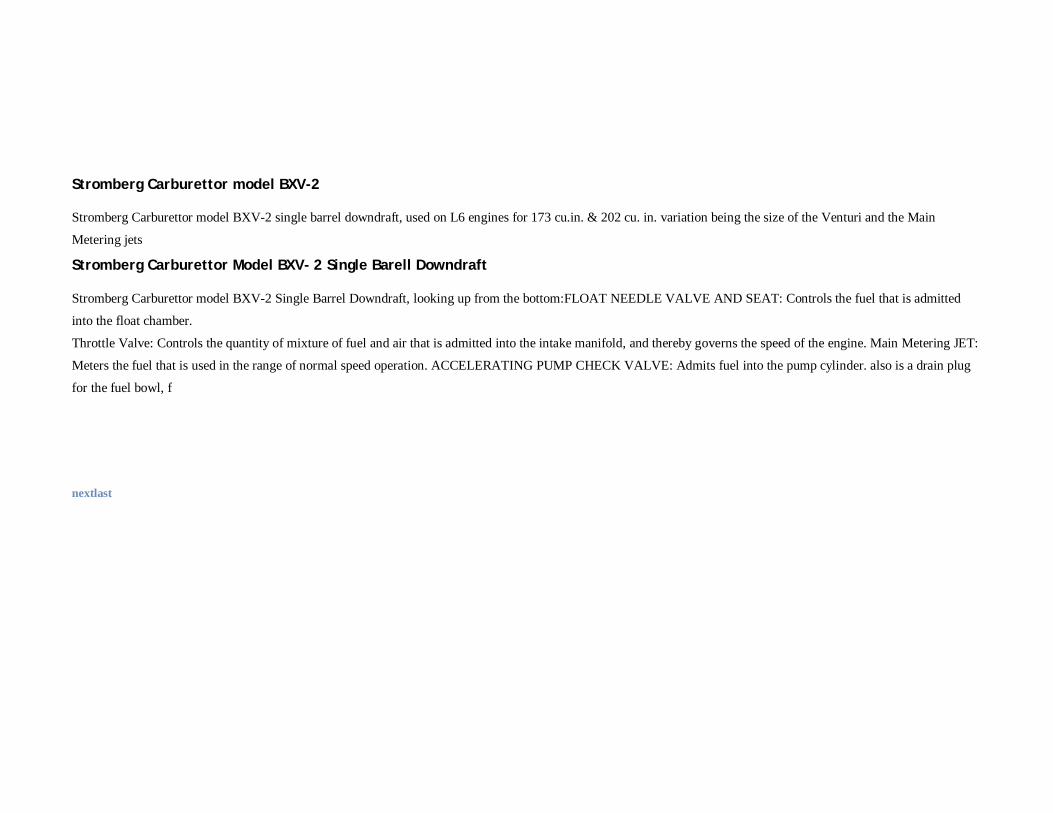
Stromberg Carburettor model BXV-2
Stromberg Carburettor model BXV-2 single barrel downdraft, used on L6 engines for 173 cu.in. & 202 cu. in. variation being the size of the Venturi and the Main
Metering jets
Stromberg Carburettor Model BXV- 2 Single Barell Downdraft
Stromberg Carburettor model BXV-2 Single Barrel Downdraft, looking up from the bottom:FLOAT NEEDLE VALVE AND SEAT: Controls the fuel that is admitted
into the float chamber.
Throttle Valve: Controls the quantity of mixture of fuel and air that is admitted into the intake manifold, and thereby governs the speed of the engine. Main Metering JET:
Meters the fuel that is used in the range of normal speed operation. ACCELERATING PUMP CHECK VALVE: Admits fuel into the pump cylinder. also is a drain plug
for the fuel bowl, f
nextlast
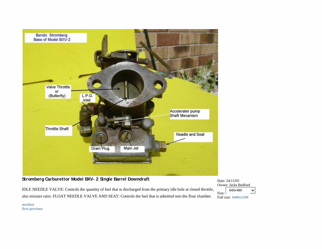
Stromberg Carburettor Model BXV- 2 Single Barrel Downdraft
IDLE NEEDLE VALVE: Controls the quantity of fuel that is discharged from the primary idle hole at closed throttle,
also mixture ratio. FLOAT NEEDLE VALVE AND SEAT: Controls the fuel that is admitted into the float chamber.
Date: 24/11/05 Owner: Jacks Bedford
Size: 640x480
Full size: 1600x1200
nextlast first previous
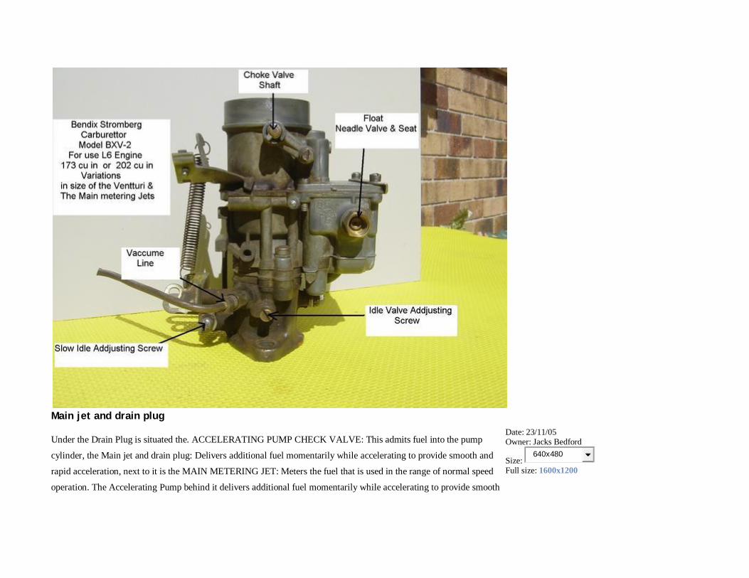
Main jet and drain plug
Under the Drain Plug is situated the. ACCELERATING PUMP CHECK VALVE: This admits fuel into the pump
cylinder, the Main jet and drain plug: Delivers additional fuel momentarily while accelerating to provide smooth and
rapid acceleration, next to it is the MAIN METERING JET: Meters the fuel that is used in the range of normal speed
operation. The Accelerating Pump behind it delivers additional fuel momentarily while accelerating to provide smooth
Date: 23/11/05 Owner: Jacks Bedford
Size: 640x480
Full size: 1600x1200
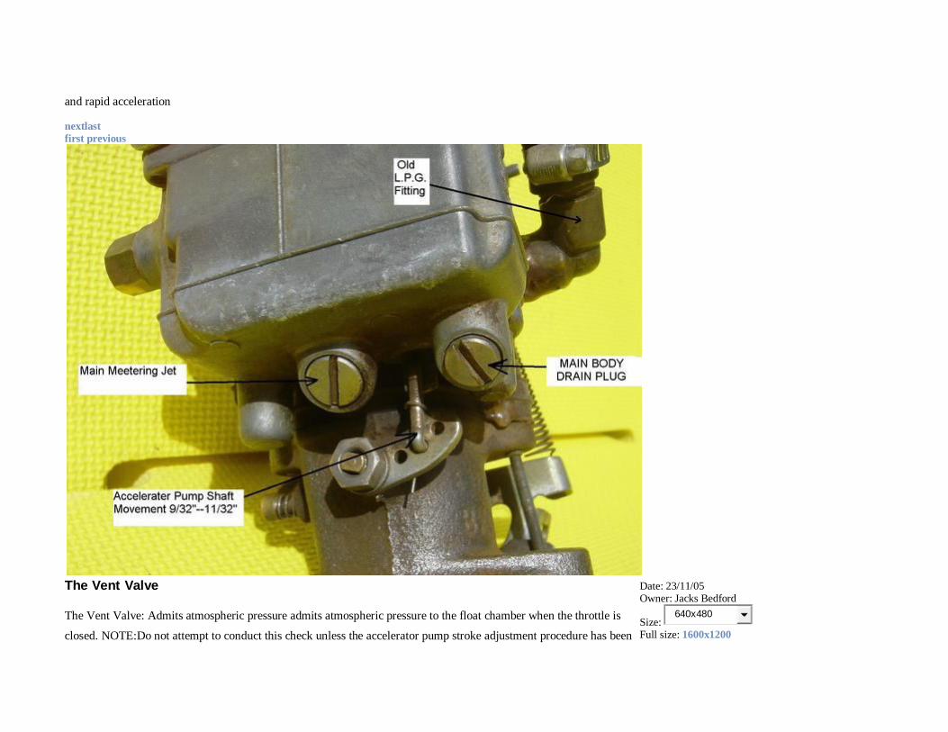
and rapid acceleration
nextlast first previous
The Vent Valve
The Vent Valve: Admits atmospheric pressure admits atmospheric pressure to the float chamber when the throttle is
closed. NOTE:Do not attempt to conduct this check unless the accelerator pump stroke adjustment procedure has been
Date: 23/11/05 Owner: Jacks Bedford
Size: 640x480
Full size: 1600x1200
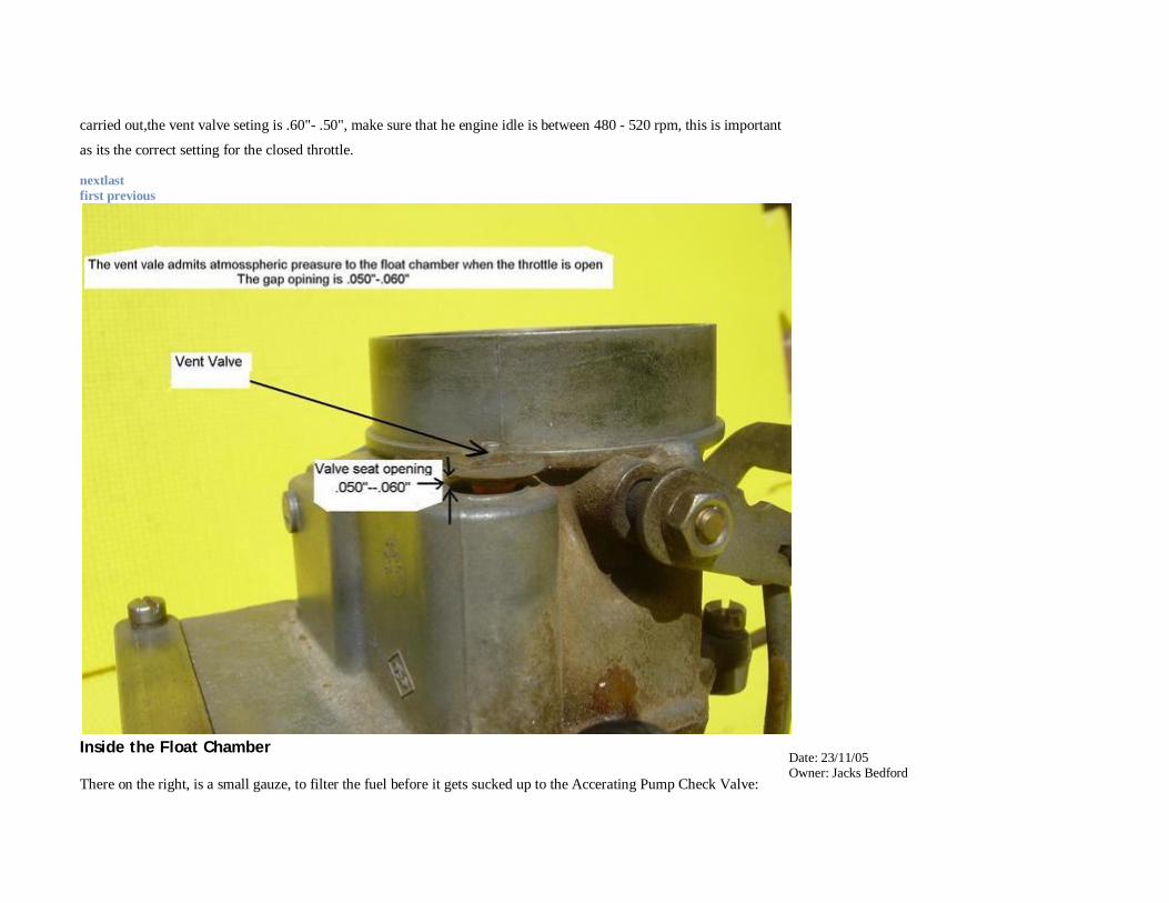
carried out,the vent valve seting is .60"- .50", make sure that he engine idle is between 480 - 520 rpm, this is important
as its the correct setting for the closed throttle.
nextlast first previous
Inside the Float Chamber
There on the right, is a small gauze, to filter the fuel before it gets sucked up to the Accerating Pump Check Valve:
Date: 23/11/05 Owner: Jacks Bedford
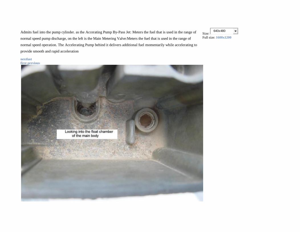
Admits fuel into the pump cylinder. as the Accerating Pump By-Pass Jet: Meters the fuel that is used in the range of
normal speed pump discharge, on the left is the Main Metering Valve:Meters the fuel that is used in the range of
normal speed operation. The Accelerating Pump behind it delivers additional fuel momentarily while accelerating to
provide smooth and rapid acceleration
Size: 640x480
Full size: 1600x1200
nextlast first previous
Inside the Float Chamber
There on the right, is a small gauze, this to filter the fuel before it gets sucked up to the Accelerating Pump Check
Valve: Admits fuel into the pump cylinder. as the Accelerating Pump By-Pass Jet: Meters the fuel that is used in the
range of normal speed pump discharge, on the left is the Main Metering Valve:Meters the fuel that is used in the range
of normal speed operation. The Accelerating Pump behind it delivers additional fuel momentarily while accelerating to
provide smooth and rapid acceleration
Date: 23/11/05 Owner: Jacks Bedford
Size: 640x480
Full size: 1600x1200
nextlast first previous
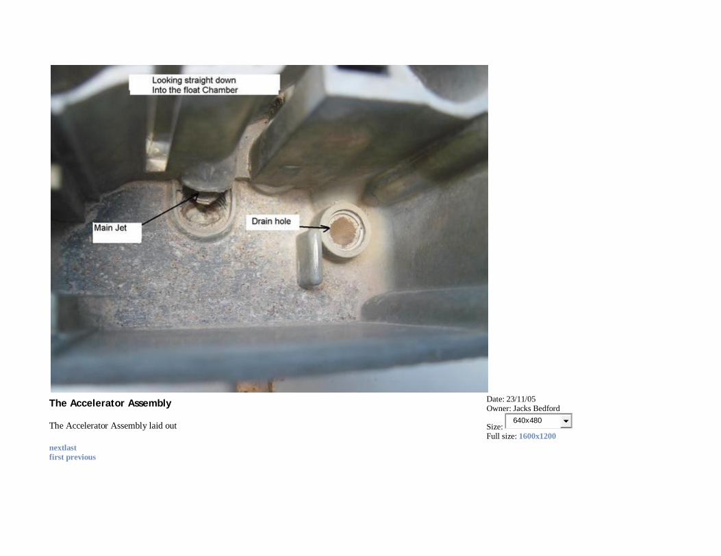
The Accelerator Assembly
The Accelerator Assembly laid out
Date: 23/11/05 Owner: Jacks Bedford
Size: 640x480
Full size: 1600x1200
nextlast first previous
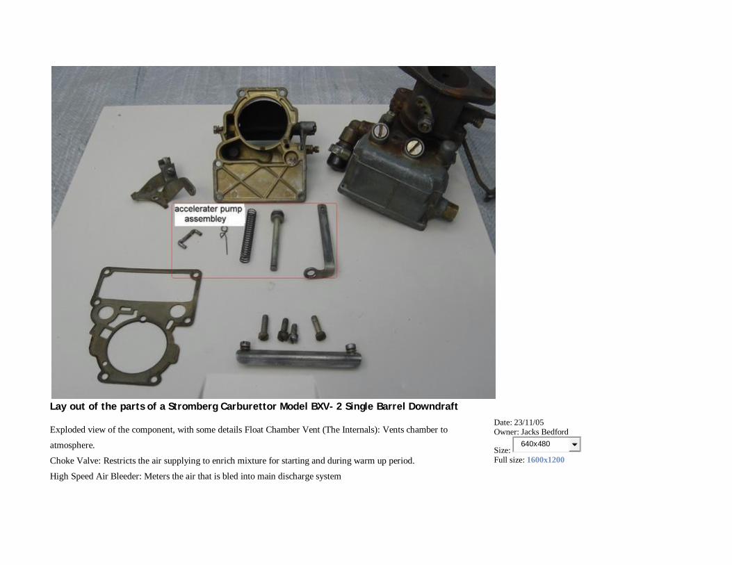
Lay out of the parts of a Stromberg Carburettor Model BXV- 2 Single Barrel Downdraft
Exploded view of the component, with some details Float Chamber Vent (The Internals): Vents chamber to
atmosphere.
Choke Valve: Restricts the air supplying to enrich mixture for starting and during warm up period.
High Speed Air Bleeder: Meters the air that is bled into main discharge system
Date: 23/11/05 Owner: Jacks Bedford
Size: 640x480
Full size: 1600x1200
Idle Tube: Meters the fuel for the idle system.
Accelerator Pump: Delivers additional fuel momentarily while accelerating to provide smooth and rapid acceleration.
Float: Maintains the fuel level in the float chamber at a definite level.
Float Needle Valve and Seat: Controls fuel that is admitted into the float chamber.
Vent Valve: Admits atmospheric pressure to
the float chamber when throttle valve is closed
nextlast first previous
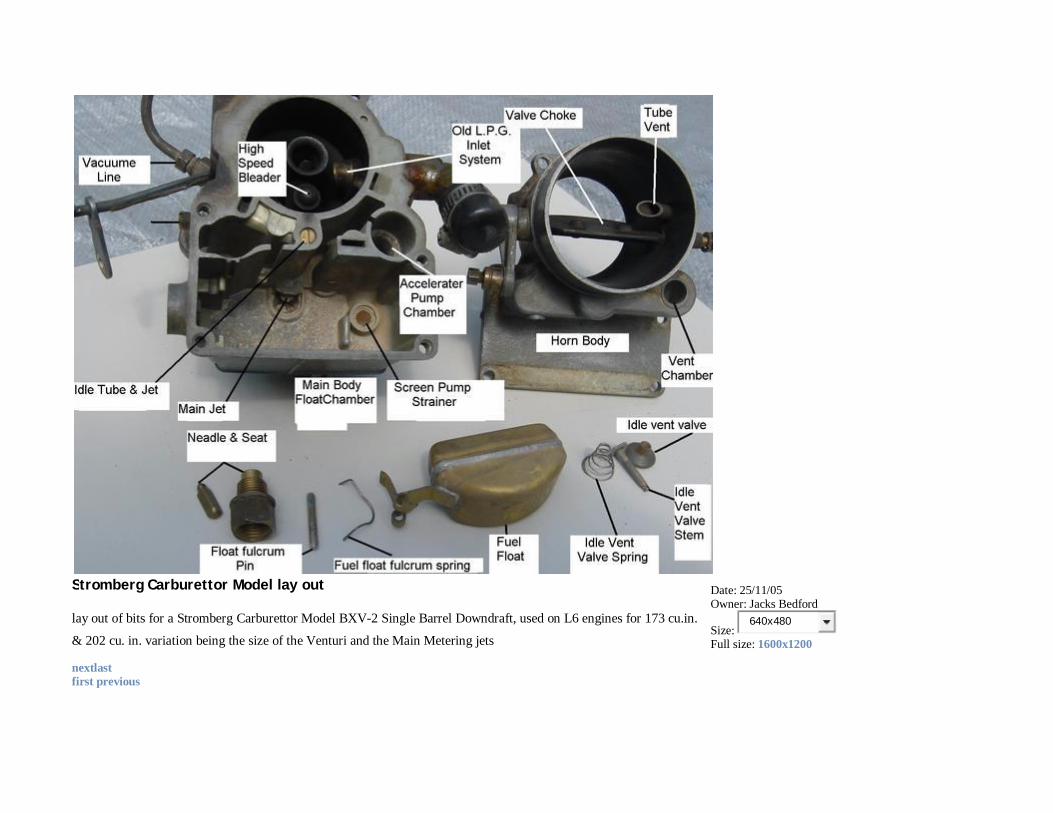
Stromberg Carburettor Model lay out
lay out of bits for a Stromberg Carburettor Model BXV-2 Single Barrel Downdraft, used on L6 engines for 173 cu.in.
& 202 cu. in. variation being the size of the Venturi and the Main Metering jets
Date: 25/11/05 Owner: Jacks Bedford
Size: 640x480
Full size: 1600x1200
nextlast first previous
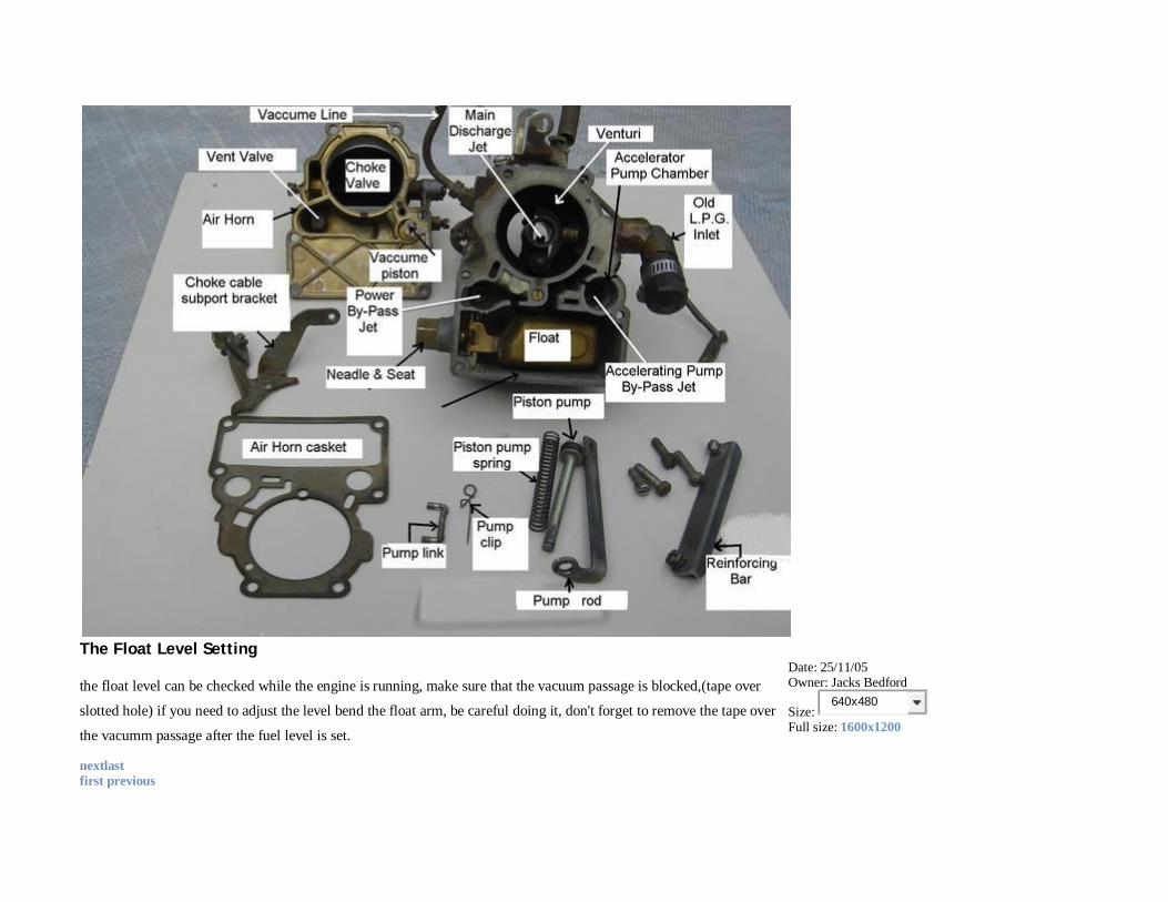
The Float Level Setting
the float level can be checked while the engine is running, make sure that the vacuum passage is blocked,(tape over
slotted hole) if you need to adjust the level bend the float arm, be careful doing it, don't forget to remove the tape over
the vacumm passage after the fuel level is set.
Date: 25/11/05 Owner: Jacks Bedford
Size: 640x480
Full size: 1600x1200
nextlast first previous
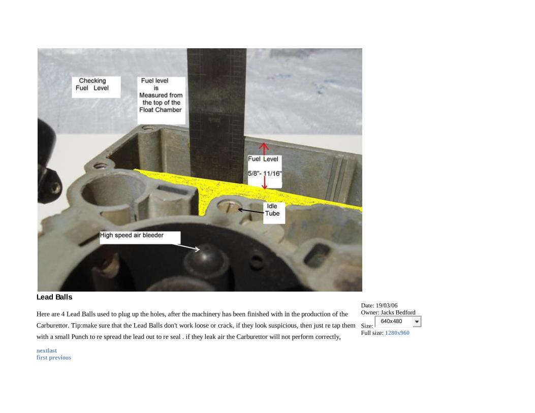
Lead Balls
Here are 4 Lead Balls used to plug up the holes, after the machinery has been finished with in the production of the
Carburettor. Tip:make sure that the Lead Balls don't work loose or crack, if they look suspicious, then just re tap them
with a small Punch to re spread the lead out to re seal . if they leak air the Carburettor will not perform correctly,
Date: 19/03/06 Owner: Jacks Bedford
Size: 640x480
Full size: 1280x960
nextlast first previous
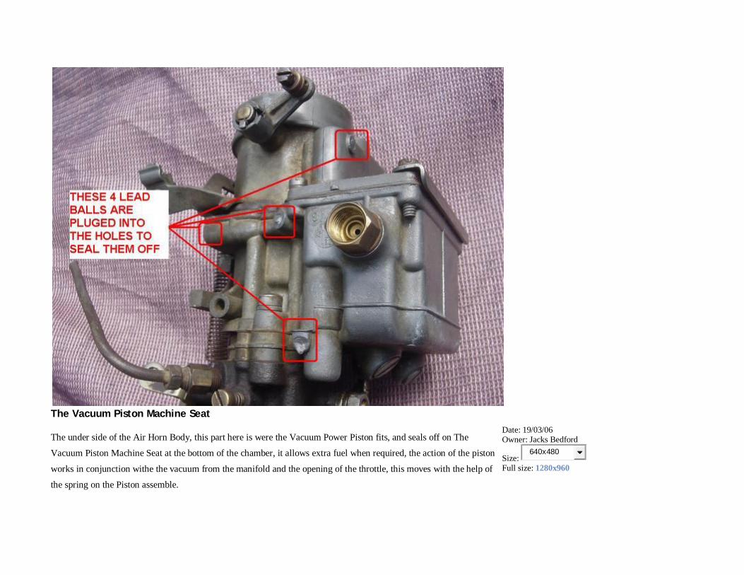
The Vacuum Piston Machine Seat
The under side of the Air Horn Body, this part here is were the Vacuum Power Piston fits, and seals off on The
Vacuum Piston Machine Seat at the bottom of the chamber, it allows extra fuel when required, the action of the piston
works in conjunction withe the vacuum from the manifold and the opening of the throttle, this moves with the help of
the spring on the Piston assemble.
Date: 19/03/06 Owner: Jacks Bedford
Size: 640x480
Full size: 1280x960
See "Holdenpedia" and search for "Stromberg" for more in depth details by "T" and myself
nextlast first previous
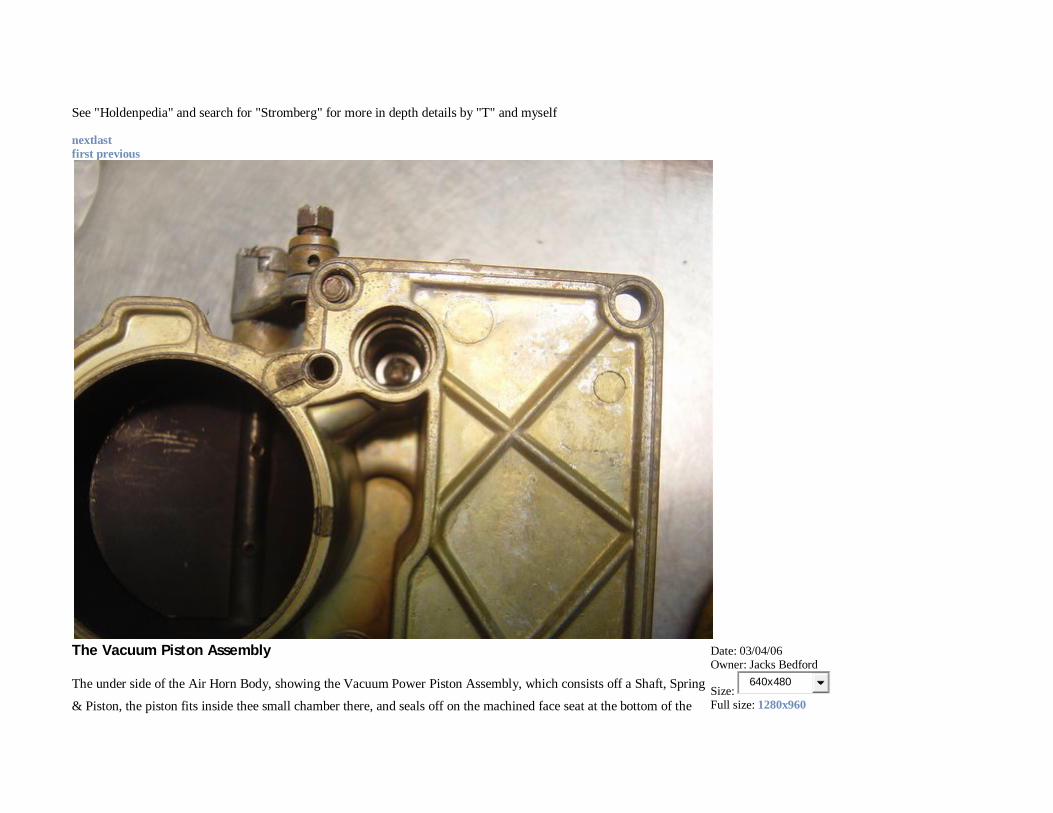
The Vacuum Piston Assembly
The under side of the Air Horn Body, showing the Vacuum Power Piston Assembly, which consists off a Shaft, Spring
& Piston, the piston fits inside thee small chamber there, and seals off on the machined face seat at the bottom of the
Date: 03/04/06 Owner: Jacks Bedford
Size: 640x480
Full size: 1280x960
chamber
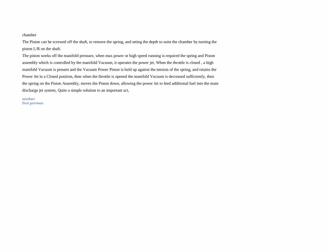
The Piston can be screwed off the shaft, to remove the spring, and seting the depth to suite the chamber by turning the
piston L/R on the shaft.
The piston works off the manifold pressure, when max power or high speed running is required the spring and Piston
assembly which is controlled by the manifold Vacuum, it operates the power jet, When the throttle is closed , a high
manifold Vacuum is present and the Vacuum Power Piston is held up against the tension of the spring, and retains the
Power Jet in a Closed position, then when the throttle is opened the manifold Vacuum is decreased sufficiently, then
the spring on the Piston Assembly, moves the Piston down, allowing the power Jet to feed additional fuel into the main
discharge jet system, Quite a simple solution to an important act,
nextlast first previous
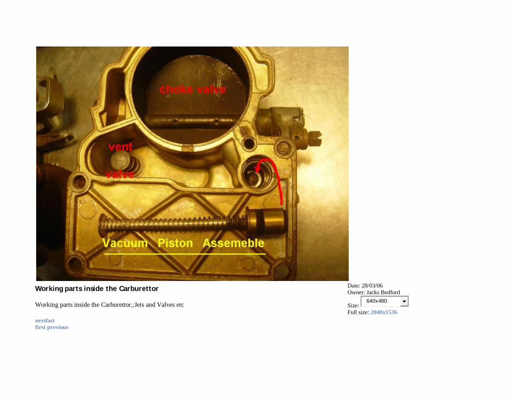
Working parts inside the Carburettor
Working parts inside the Carburettor,:Jets and Valves etc
Date: 28/03/06 Owner: Jacks Bedford
Size: 640x480
Full size: 2048x1536
nextlast first previous
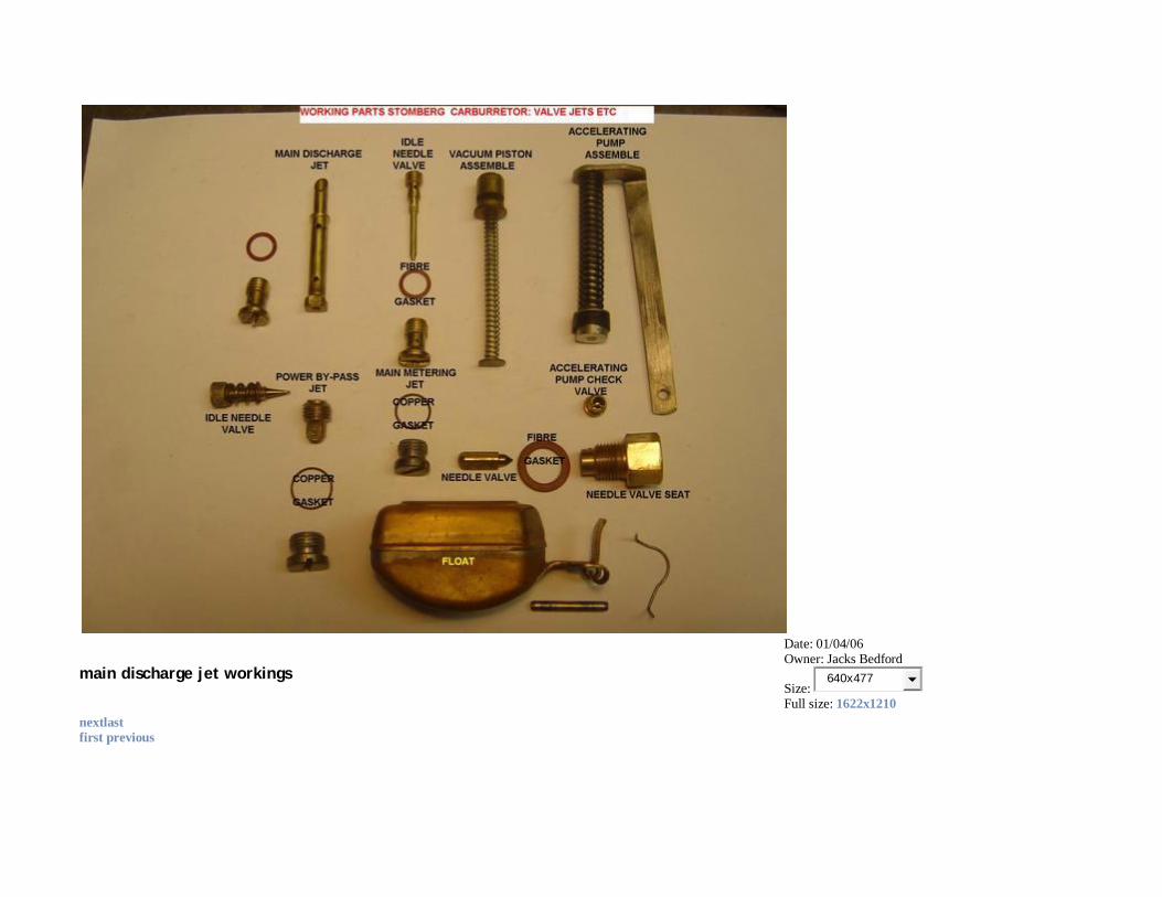
main discharge jet workings
Date: 01/04/06 Owner: Jacks Bedford
Size: 640x477
Full size: 1622x1210
nextlast first previous
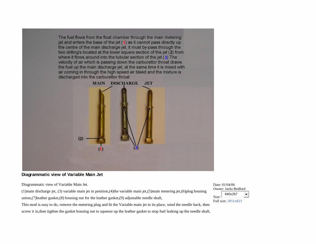
Diagrammatic view of Variable Main Jet
Diagrammatic view of Variable Main Jet.
(1)main discharge jet, (3) variable main jet in position,(4)the variable main jet,(5)main metering jet,(6)plug housing
union,(7)leather gasket,(8) housing nut for the leather gasket,(9) adjustable needle shaft,
This mod is easy to do, remove the metering plug and fit the Variable main jet in its place, wind the needle back, then
screw it in,then tigthen the gasket housing nut to squeeze up the leather gasket to stop fuel leaking up the needle shaft,
Date: 01/04/06 Owner: Jacks Bedford
Size: 640x257
Full size: 2051x823
don't over do it, then wind in needle shaft till it bottoms, then come back about 1 1/2 turns, and fiddle till you have it
right, good luck.
nextlast first previous
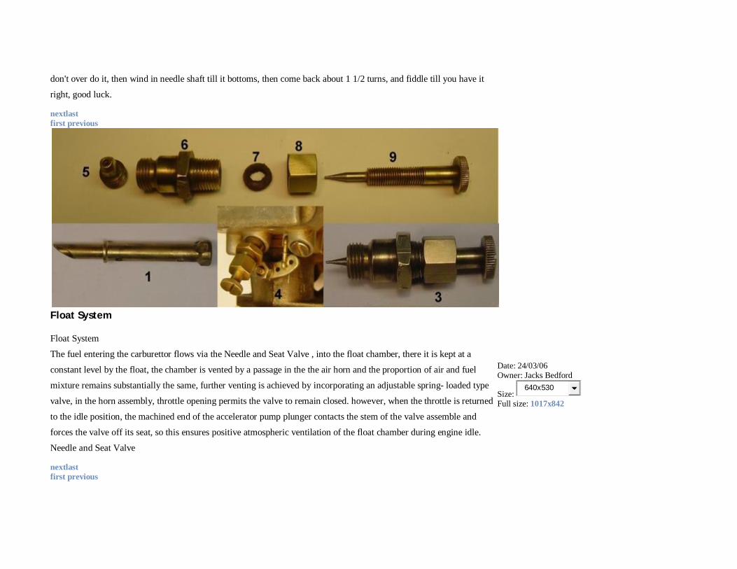
Float System
Float System
The fuel entering the carburettor flows via the Needle and Seat Valve , into the float chamber, there it is kept at a
constant level by the float, the chamber is vented by a passage in the the air horn and the proportion of air and fuel
mixture remains substantially the same, further venting is achieved by incorporating an adjustable spring- loaded type
valve, in the horn assembly, throttle opening permits the valve to remain closed. however, when the throttle is returned
to the idle position, the machined end of the accelerator pump plunger contacts the stem of the valve assemble and
forces the valve off its seat, so this ensures positive atmospheric ventilation of the float chamber during engine idle.
Needle and Seat Valve
Date: 24/03/06 Owner: Jacks Bedford
Size: 640x530
Full size: 1017x842
nextlast first previous
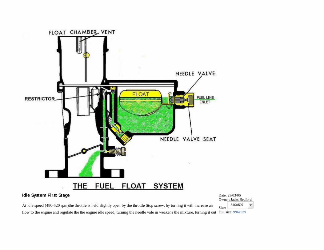
Idle System First Stage
At idle speed (480-520 rpm)the throttle is held slightly open by the throttle Stop screw, by turning it will increase air
flow to the engine and regulate the the engine idle speed, turning the needle vale in weakens the mixture, turning it out
Date: 23/03/06 Owner: Jacks Bedford
Size: 640x597
Full size: 996x929

richens the mixture
nextlast first previous
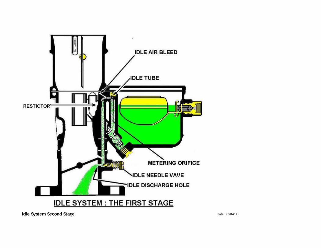
Idle System Second Stage Date: 23/04/06

When the throttle valve is open, it uncovers the idle Discharge holes located above the the throttle valve, thus giving
more suction ,so this then delivers more fuel from the Idle Discharge Holes.
Owner: Jacks Bedford
Size: 640x545
Full size: 1002x854
nextlast first previous

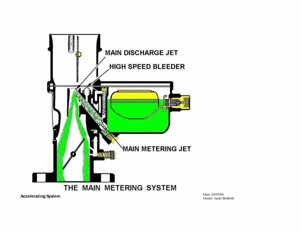
Main Metering System
The Main Metering System controls the flow of fuel during the intermediate, fuel flows through the Main Metering Jet
and enters the base of the that jet, it's then by-passes through the two Small Drilling's in the lower square section of the
Date: 04/04/06 Owner: Jacks Bedford
Size: 640x578
Full size: 935x844

jet, and there it flows up the tubular section of the jet. The velocity of the carburetor throat draws the fuel up the Main
Discharge Jet, it's then mixed with the air coming in through the High Speed Air Bleed ,and this mixture is then
discharged down the throat of the carby. One of the features of this set up, is that the fuel vapor bubbles which forms
in a hot carburetor, follow the outside channel around the main discharge jet, there it collects and condense in the
dome-shaped high speed air bleed, there by Percolation is eliminated
nextlast first previous
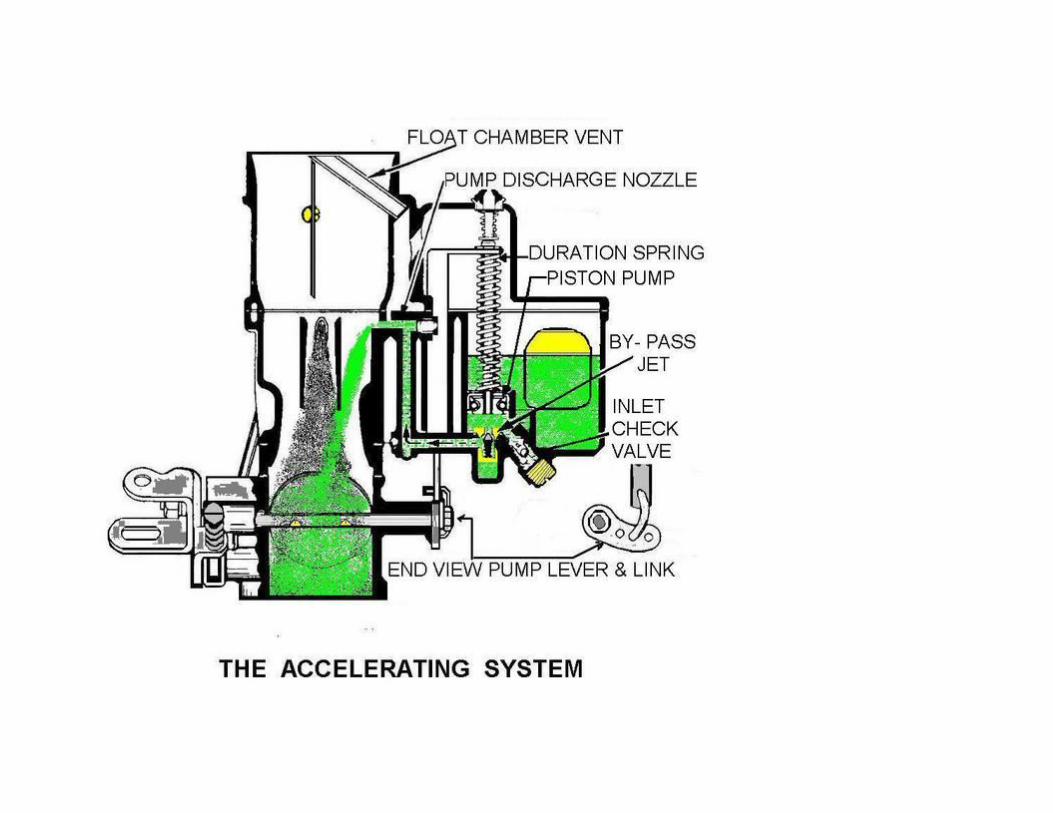
Accelerating System Date: 24/03/06 Owner: Jacks Bedford
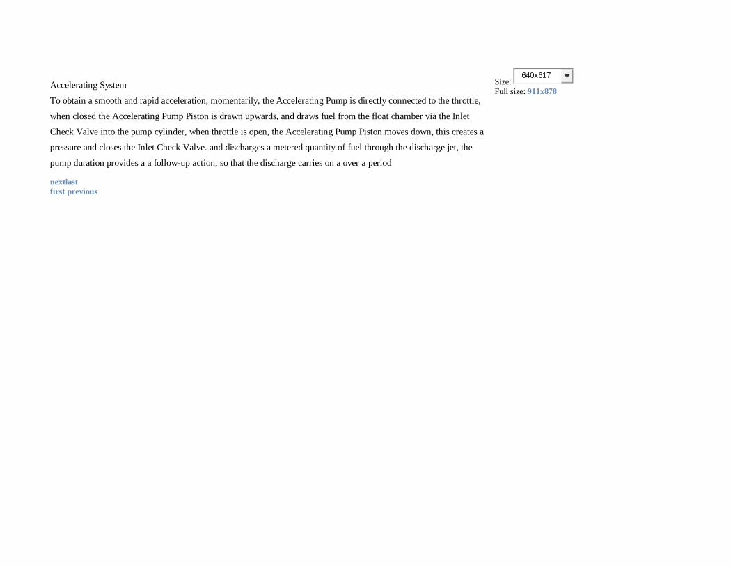
Accelerating System
To obtain a smooth and rapid acceleration, momentarily, the Accelerating Pump is directly connected to the throttle,
when closed the Accelerating Pump Piston is drawn upwards, and draws fuel from the float chamber via the Inlet
Check Valve into the pump cylinder, when throttle is open, the Accelerating Pump Piston moves down, this creates a
pressure and closes the Inlet Check Valve. and discharges a metered quantity of fuel through the discharge jet, the
pump duration provides a a follow-up action, so that the discharge carries on a over a period
Size: 640x617
Full size: 911x878
nextlast first previous
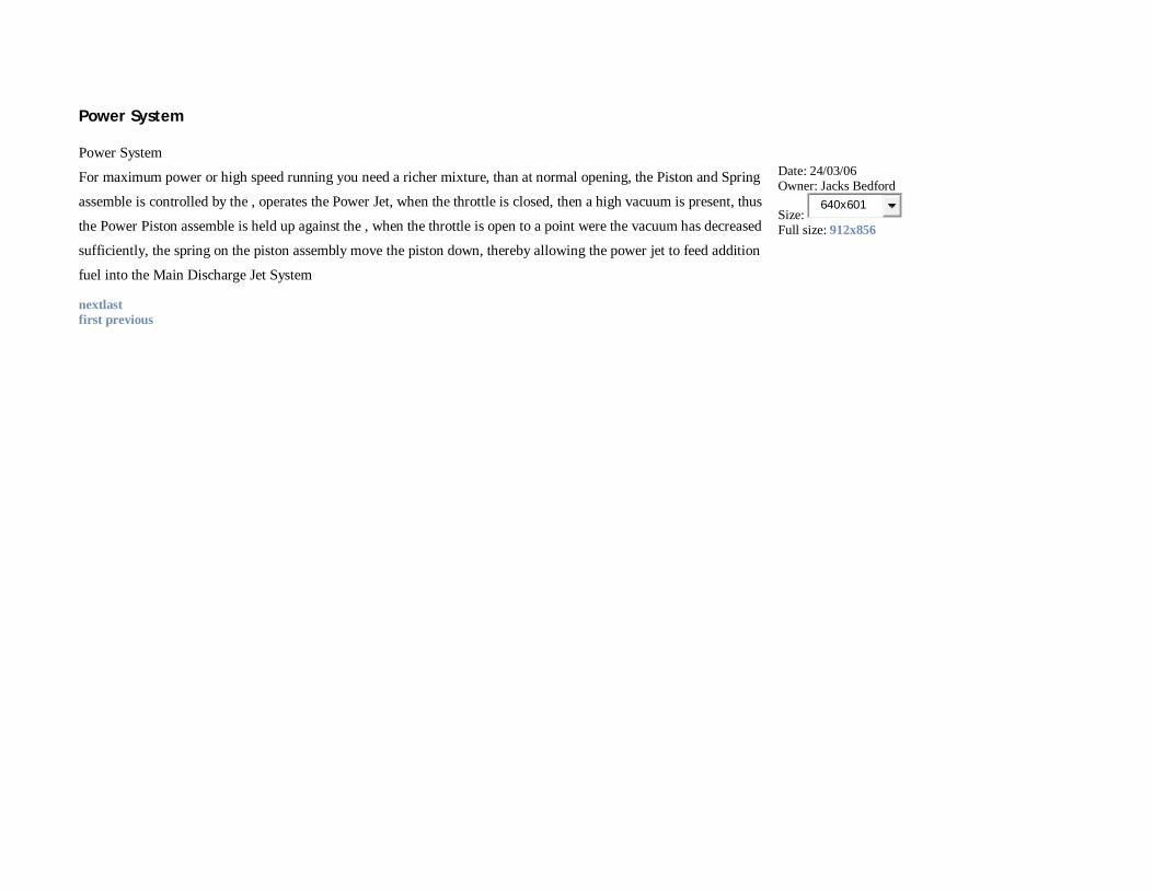
Power System
Power System
For maximum power or high speed running you need a richer mixture, than at normal opening, the Piston and Spring
assemble is controlled by the , operates the Power Jet, when the throttle is closed, then a high vacuum is present, thus
the Power Piston assemble is held up against the , when the throttle is open to a point were the vacuum has decreased
sufficiently, the spring on the piston assembly move the piston down, thereby allowing the power jet to feed addition
fuel into the Main Discharge Jet System
Date: 24/03/06 Owner: Jacks Bedford
Size: 640x601
Full size: 912x856
nextlast first previous
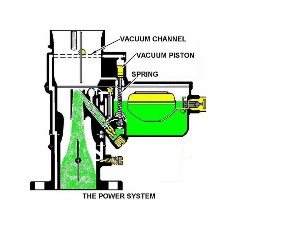

Choke System
Choke System, when starting a cold engine richer mixture is required, the increase in fuel to air ratio is done by
closing the Choke Valve, this shuts off the entry of air into the carbby, when the engine fires slowly open the the
valve, when the engine is hot the valve must be fully opened gain for even running of the engine
Date: 24/03/06 Owner: Jacks Bedford
Size: 640x577
Full size: 985x888
nextlast first previous
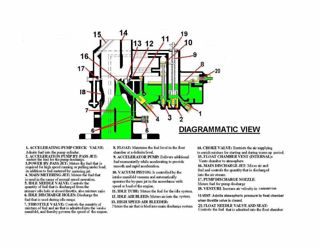
Diagrammatic View Date: 28/03/06 Owner: Jacks Bedford

Diagrammatic View showing what's what and a brief description of the workings.
The original diagram was done by "T" and taken from the "Holdenpedia" section on Stromberg Carburettor,for more
information <a href="
http://gallery.oldholden.com/Jack_s/Stromberg+Carburettor+model+BXV-2/ Jacks sheds "></>here</a>
Size: 640x450
Full size: 1207x849
first previous