BX-80NR - OPTEX · nAvoid adjusting the horizontal angles of only the upper or lower detection...
6
Optex presents a new concept, , which protects a building's exterior by detecting intruders before an entry is attempted. In addition to signaling an alarmsystem. BX-80NR is a passive infrared detector which detects the infrared heat energy that is emitted by humans and is designed with this concept. Read instructions completely before beginning installation. INSTALLATION INSTRUCTIONS 5913801 Features : IP rating IP 55 Before installation, make sure to read this instruction manual carefully for safe and effective product operation. This icon denotes a situation involving the risk of serious injury or even death, if the warning given is ignored. This icon denotes a situation involving the risk of serious injury or damage to property if the warning given is ignored. This icon indicates actions to be avoid. Details of the actions to be avoided are written beside or near icon. ( The icon on the left indicates that the product must not be dissembled ) Never use this product for any applications except as stated above or unexpected accidents can occur. Never attempt to disassemble or modify the product, which increases the risk of fire or damage of the product. Never attempt to connect the terminals to units which require higher power supply or current draw than its rating. It increases the risk of fire or damage to the product. Avoid applying water directly from buckets, houses, or otherwise splashing water directly onto the product. It increases the risk of damaging the product. The horizontal and vertical angle of detection areas are inde- pendently adjustable on both the right and left sides of the detector. (See section 7. AREA SETUP) C O N T E N T S 1. SAFETY-RELATED PRECAUTIONS 2. DETECTION AREA 3. PARTS IDENTIFICATION 4. INSTALLATION HINTS 5. INSTALLATION 6. WIRING 7. AREA SETUP 8. FUNCTION SETUP 9. WALK TEST 10. SPECIFICATIONS & DIMENSIONS 11. TROUBLE SHOOTING 5-1 Before the Installation 5-2 Mounting 7-1 Area Angle Adjustment 7-2 Detection Length Adjustment 8-1 Sensitivity Adjustment 8-2 DIP Switch Setup 5.High offset mounting design 6.Limited detection range function 7.Size judging function 8.Waterproof : The detection range of the BX-80NR can be limited to avoid detecting unwanted objects. By limiting the detection range, false alarms due to unwanted movement (i.e. cars, persons or animals outside of the protected area) can be reduced. : BX-80NR is designed to discriminate between large and small objects. By utilizing this ability, false alarms due to small animals can be reduced. WARNING CAUTION WARNING CAUTION IMPORTANT B X - 8 0 N R This product detects temperature differences between the moving target and the background temperature of the detec- tion area. So, if the target does not move, the detector can not detect it. Additionally, the temperature of the target may affect the detector's maximum detection range. 9.Double conductive shielding : This patent listed shielding greatly reduces the risk of false alarms due to car headlights, sunlight and other ambient light sources. 12 10 5 30 (ft) 40 20 10 5 12 20 40 (m) (ft) 10 10 30 (m) 20 30 (ft) 10 5 10 5 10 10 (m) 12 20 12 30 40(ft) (m) 40 10 (m) 40 20 30 (ft) 12 10 5 5 30 10 0 (m) 0 5 10 12 (ft) 40 0 30 20 10 20 12 (m) (ft) (m) 3.3 1 (ft) 10 0 40 0 0 3.3 0 (ft) 1 (ft) (m) 3.3 0 (ft) (m) 3.3 1 0 1 (m) 0 Approx. 1.4m (4.6ft.) at 40ft.(12m) [ POSITION B ] [ POSITION D ] [ POSITION C ] Top View [ POSITION A ] Side view of detection area:2m(6.7ft.)(single side) Side view of detection area:5m(16.7ft.)(single side) Side view of detection area:8m(26.7ft.)(single side) Side view of detection area:12m(40ft.)(single side) The angles of all detection areas are adjustable horizontally 0 or 3 degrees. The angles of all detection fingers are adjustable horizontally 0 or 3 degrees. 1.Low current draw : 15uA(standby) 2.Battery saving circuit : Alarm signal is generated only once with in a selected finer period, 5 or 120 seconds. 3.Operates on wide range of power : 3-9V lithium battery or alkaline battery. 4.Back box for a wireless transmitter : Back box can conceal a wireless transmitter. (Max. W40mm H126mm D50mm) 5-3 Mounting on a gutter 5-4 Wall Tamper 6-1 Terminals 6-2 Setting up Transmitter : Avoid areas with unwanted objects.(80mm) 1. SAFETY-RELATED PRECAUTIONS 2. DETECTION AREA
Transcript of BX-80NR - OPTEX · nAvoid adjusting the horizontal angles of only the upper or lower detection...

Optex presents a new concept, , which protects a building's exterior by detecting intruders before an entry is attempted. In addition to signaling an
alarmsystem.
BX-80NR is a passive infrared detector which detects the infrared heat energy that is emitted by humans and is designed with this concept.
Read instructions completely before beginning installation.
INSTALLATION INSTRUCTIONS
5913801
Features
: IP rating IP 55
Before installation, make sure to read this instruction manual carefully for safe and effective product operation.
This icon denotes a situation involving the risk of serious injury or even death, if the warning given is ignored.
This icon denotes a situation involving the risk of serious injury or damage to property if the warning given is ignored.
This icon indicates actions to be avoid. Details of the actions to be avoided are written beside or near icon.
( The icon on the left indicates that the product must not be dissembled )
Never use this product for any applications except as stated above or unexpected accidents can occur.
Never attempt to disassemble or modify the product, which increases the risk of fire or damage of the product.
Never attempt to connect the terminals to units which require higher power supply or current draw than its rating.
It increases the risk of fire or damage to the product.
Avoid applying water directly from buckets, houses, or otherwise splashing water directly onto the product. It increases
the risk of damaging the product.
The horizontal and vertical angle of detection areas are inde-
pendently adjustable on both the right and left sides of the
detector. (See section 7. AREA SETUP)
C O N T E N T S1. SAFETY-RELATED PRECAUTIONS
2. DETECTION AREA
3. PARTS IDENTIFICATION
4. INSTALLATION HINTS5. INSTALLATION
6. WIRING
7. AREA SETUP
8. FUNCTION SETUP
9. WALK TEST10. SPECIFICATIONS & DIMENSIONS
11. TROUBLE SHOOTING
5-1 Before the Installation5-2 Mounting
7-1 Area Angle Adjustment7-2 Detection Length Adjustment
8-1 Sensitivity Adjustment8-2 DIP Switch Setup
5.High offset mounting design
6.Limited detection range function
7.Size judging function
8.Waterproof
: The detection range of the BX-80NR can be limited to avoid detecting unwanted objects. By limiting
the detection range, false alarms due to unwanted movement (i.e. cars, persons or animals outside of
the protected area) can be reduced.
: BX-80NR is designed to discriminate between large and small objects. By utilizing this ability, false
alarms due to small animals can be reduced.
WARNING
CAUTION
WARNING
CAUTION
IMPORTANT
BX-80NR
This product detects temperature differences between the
moving target and the background temperature of the detec-
tion area. So, if the target does not move, the detector can
not detect it. Additionally, the temperature of the target may
affect the detector's maximum detection range.
9.Double conductive shielding : This patent listed shielding greatly reduces the risk of false alarms due to car headlights,
sunlight and other ambient light sources.
1210530 (ft)4020
105 1220 40
(m)(ft)
10
10 30
(m)
20 30 (ft)10
5 10
5 10
10
(m)12
2012
30 40(ft)(m)
40
10(m)
4020 30 (ft)12105
530 10
0
(m) 051012(ft) 40 030 20 10
2012(m)
(ft) (m)3.3 1
(ft)10
040
00
3.3
0
(ft)
1
(ft) (m)
3.3
0
(ft) (m)
3.3 1
0
1
(m)
0
Appro
x.
1.4
m (
4.6
ft.)
at 40ft.(
12m
)
[ POSITION B ]
[ POSITION D ]
[ POSITION C ]
Top View
[ POSITION A ]
Side view of detection area:2m(6.7ft.)(single side)
Side view of detection area:5m(16.7ft.)(single side)
Side view of detection area:8m(26.7ft.)(single side)
Side view of detection area:12m(40ft.)(single side)
The angles of all detection areas are adjustable horizontally 0 or 3 degrees.
The angles of all detection fingers are adjustable horizontally 0 or 3 degrees.
1.Low current draw : 15uA(standby)
2.Battery saving circuit : Alarm signal is generated only once with in a selected finer period, 5 or 120 seconds.
3.Operates on wide range of power : 3-9V lithium battery or alkaline battery.
4.Back box for a wireless transmitter : Back box can conceal a wireless transmitter. (Max. W40mm H126mm D50mm)
5-3 Mounting on a gutter5-4 Wall Tamper
6-1 Terminals6-2 Setting up Transmitter
: Avoid areas with unwanted objects.(80mm)
1. SAFETY-RELATED PRECAUTIONS
2. DETECTION AREA
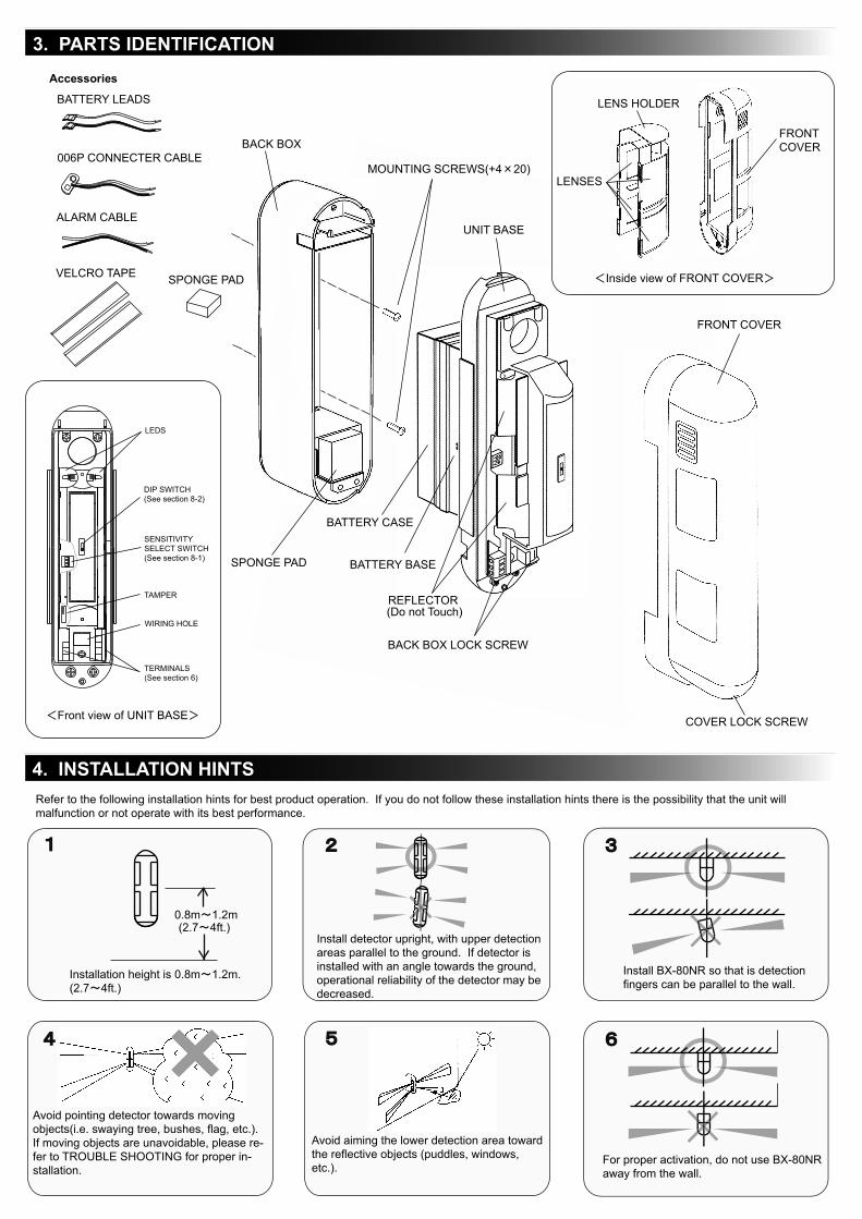

5-1.Before the installation
5-2.Mounting
5-3.Mounting on a gutter
5-4.Wall Tamper
MOUNTING TEMPLATE
Use the knockout on the backside of the
BACK BOX.
Use the metal strap to fix the unit. Tightly strap
the unit on a gutter.
(Max strap size : Width 20mm / Thickness
0.5mm) Make sure if the unit is tightly strapped.
Use the enclosed MOUNTING TEMPLATE
to determine where it is to be installed.
Magnetic contact with cable should be fixed on
the bottom part of the BACK BOX.After BACK BOX is installed, magnetic con-
tact should be connected with tamper termi-
nal through the cable hole.
2
1
5. INSTALLATION
In case detection can be blocked by unwanted object it is possible to mount a gutter using Metal strap.
*Use Metal strap on the market as it is not included on this package. (Max strap size : Width 20mm / Thickness 0.5mm)
Loosen the BACK BOX LOCK SCREWS.
Do not touch the REFLECTORS.Remove the BACK BOX by sliding it down
and away from the UNIT BASE.
Loosen the COVER LOCK SCREW and
remove the FRONT COVER.
Do not touch the LENS surface.
Use the MOUNTING TEMPLATE. Then hold
the template against the mounting surface,
when BX-80NR is to be mounted. Mark the
position of the mounting hole then discard
template. Then fasten the unit on the marked
position.
After cabling between transmitter and the
unit can be fixed with 2 screws. Hook the
unit onto the BACK BOX fasten turn 2 lock
screws on the unit below.
Put the cover on and conduct walk test. After
completed turn the lock screw on the cover.
Magnetic contact can be used as a wall tamper. *Use Magnetic contact on the market as it is not included on this package.
As for the fitting size, refer to Dimension of Magnetic contact. (See section 10. )

Avoid adjusting the horizontal angles of only the upper or lower detection finger separately. BX-80NR requires both upper and lower fingers to be
blocked to make an alarm. So, if you adjust the horizontal angle of the detection areas, do it for both of them together. When the both angle are
adjusted horizontally, sensitivity adjustment should be set to [ H ] . (See Section 8-1.Sensitivity Adjustment)
IMPORTANT
7-1. Area Angle Adjustment
Because of the detection fingers should be set at the same angle from the wall so that they are triggerd at the same time. In this case, sensitivity [H] is recommended
when greater sensitivity is requiewd around the rated area (near 12m).
6-2.Setting up Transmitter
6-1. Terminals
Appro
x. 0.6
m(1
.97ft)
WALL
When using BX-80NR and transmitter together, the battery life will be shortened depending
on the transmitter type (current draw). Only the expected battery life of BX-80NR is shown
in the following chart. Battery life will change according to the temperature.
Battery Life
(BX-80NR only )
Approx. 2.5 years /9V Alkaline Battery(560mAh), Interval 120sec
Approx. 2 years /9V Alkaline Battery(560mAh), Interval 5sec
Approx. 6 years /3V Lithium Battery(1300mAh), Interval 120sec
Approx. 5 years /3V Lithium Battery(1300mAh), Interval 5sec
In case that BX-80NR is powered by trans-
mitter's battery, use enclosed BATTERY LEADS.
Press each lug of the lead between battery
terminal and battery holder. Use enclosed alarm cable to connect with
alarm imput terminal and draw cables out
and close the cover.
Use VELCRO TAPE to fix the transmitter in
BATTERY BASE.
Draw cables from the bottom part of the BAT-
TERY BASE to pass through cable hole of the
unit. Close the BATTERY CASE.
Connects cables to each terminal.
Power Input (3 VDC)
Alarm Output (COM.)
Tamper N.C.
AL
M.
CO
M-
NC
NO
NC
CO
NO
TA
M P
ER
+
Tamper COM.
Tamper N.O.
Alarm Output (N.C.)
Alarm Output (N.O.)
VELCRO TAPE
+-
BATTERY LEAD(red)
BATTERY LEAD(black)
Note Do not strip the cable just before con-
necting with power terminals!!
(Prevent from the short-circuit)
6. WIRING
7. AREA SETUP
*Data shown here is when the LED is off. Battery life becomes shorter when the LED is on.
Remove the BATTERY CASE from
the BATTERY BASE.
Unhook the three tabs on each side of the LENS HOLDER by inserting the blade of a
screwdriver as shown above. Then, remove the LENS HOLDER from the FRONT COVER
by holding the knobs on the LENS HOLDER.
Move the LENS to select the angle (0 or 3 degree) of the detection areas as shown above
and confirm that the LENS is unhooked from the groove on the LENS HOLDER.
After selecting the detection area adjustment,
replace the LENS HOLDER in the FRONT COVER by
aligning the three tabs (A, B and C) on each side of
the LENS HOLDER with the three grooves (A' , B' and
C') on the FRONT COVER.
If you select the 3 degree angle, the detection area will be 0.6m(1.97ft.)
away from the wall at 12m(40ft.).
If there are obstacle blocking the detection fingers, the angle of the fingers can be adjustable horizontally with the lens setting 0 or 3 degrees to keep a distance from the obstacle.
AL
M.
CO
-N
NO
NC
CO
MN
OTA
M P
ER

Confirm detection area referring to this section.
8. FUNCTION SETUP
9. WALK TEST
8-1.Sensitivity Adjustment
8-2.DIP Switch Setup
Walk test should be conducted annually.
If LED are not activated when detection fingers are blocked, or LED are activated while there is nothing to detect in detection area,
see section 11 TROBLE SHOOTING.
When greater sensitivity is desired, select [H].
When the installation site is poor(bad conditions) select [L].
Sensitivity [H] is recommended when:
1. The angles of detection areas are changed in horizontal direction.
2. Greater sensitivity is required around the end of detection area(near 12m)
Adjust the detection length by sliding the lower lens as shown. (The lower areas are adjustable on right and left sides independently.) Do not press hard.
Remove the LENS HOLDER from the FRONT COVER as described in section 7-1.The lower lens slides to adjust the detection length. Select the appropriate position from the guide on the LENS HOLDER (A,B,C, or D).Make sure to conduct walk tests after changing the position. The LED light (see section 8-2) can be used to identify detection areas. If the detec-tion areas are not appropriate, re-adjust the detection length by sliding the lens to a different position on the LENS HOLDER.
The lower detection finger can be adjusted to control the detection length as shown below: [ Detection length setting chart ]
Installation height must be between 0.8m 1.2m(2.7 4ft.).Detection range depends on installation height.
The upper detection finger stays parallel to the ground at all times. The
lower detection finger moves as shown in the section depending on the
position. So, the length of detection is limited by the angle of lower finger,
since both upper & lower fingers have to be blocked at the same time to
activate detector.
Both upper and lower
finger are blocked!
Detection!
Only lower finger is
blocked!
Only upper finger is
blocked!
No
Detection
No
Detection
IMPORTANT
7-2. Detection Length Adjustment
105
12
1240(ft)
(m)
(m)
40(ft)
20 30
(m)12
(m)
3.3
(ft)
1
(ft)
(m)
(m)
3.3
(ft) (m)
3.3 1
5
20 30
10 20 30
(ft)(m)12
40
10
10
10
10
[ POSITION B ]Side view of detection
[ POSITION D ]Side view of detection
[ POSITION C ]Side view of detection
[ POSITION A ]Side view of detection
3.3 1
1
(ft)
50 30 (ft)4020
510
100
0
0
0
0
0
0
(single side)
(single side)
(single side)
(single side)
Next, make sure to switch off the WALK TEST MODE. Then, conduct walk tests near by the windows to be protected by BX-80NR and
confirm if it alarms. If there is no alarm during the walk tests, the detection areas are not developed properly on horizontal direction.
In this case, please see section 7 AREA SETUP and confirm if the areas are properly developed.
POSITIONMAX DETECTION LENGTH m(ft)
Standard *
12.0
8.0
5.0
2.0
(40.0)
(26.7)
(16.7)
(6.7)
10.0 - 15.0
(33.3 - 50.0)
6.0 - 10.0
(20.0 - 33.3)
4.0 - 6.0
(13.3 - 19.8)
1.5 - 3.0
( 5.0 - 9.9)
*The maximum detection length may vary as above due to
environmental thermal conditions.
Instration height=1m(3.3ft)
3
ON
1 2
ON
OF
F 5
s
TE
ST
120s
NO
RM
.
3. LED Indicator Select LED Indicator status : [ON] or [OFF].
2. BATTERY SAVING TIMER Alarm output activations are limited by a timer selection 5 or 120 seconds.
Even if there are continuous alarm events, the alarm is generated only once
in the timer period which can be 5 or 120 seconds.
1. WALK TEST MODE
120s : The factory set timer position.
5s : If frequent alarm transmission is requires select the "5s" option.
Battery life will be shortened when using the "5s" setting.
TEST (Walk test mode)
LED will light when detector is tripped.Alarm will be generated instantly on detection.
NORM. (Normal operation : Battery saving mode)LED is off. (When LED SW is OFF.)
SENS
L
M
H

Detectable Speed
Power Input
This unit is designed to detect movement of an intruder and activate an alarm control panel. Being only a part of a complete system, we cannot accept
responsibility for any damages or other consequences resulting from an intrusion. This product confirms to the EMC Directive 89/336 EEC.
PROBLEM PROBABLE CAUSE REMEDY
Incorrect power supply voltage.
Faulty wiring to detector. Transmitter is not
connected to BX-80NR
Wireless transmission does not reach the receiver.
Battery is dead.
Normal Performance. Refer to section "8-2.2.
BATTERY SAVING TIMER" and "8-2.1.WALK TEST MODE".
No alarm event even though
someone is walking in
detection area.
LED blinks continuously
Make alarms even though no
moving object is in the area
No detection occasionally
Incorrect power supply voltage.
Detector is not installed perpendicular to the ground.
Lower detection area is unnecessarily long.
Lower detection area any object.
Lower detection area is exposed to direct sunlight or
car light.
There is a heat source (stove or heater, etc.) in the
area that may cause temperature change.
There is a moving object (laundrt on clothesline,
plants, etc.) in the area.
Detection area is not set appropriately.
Sensitivity is set for L(ow)
Set supply voltage for a range of 3 to 9VDC battery.
Rewire alarm correcty.
Check transmitter.
Change battery.
Battery saving timer is working.
Reinstall the detector perpendicular to the ground.
Confirm and reset the detection area.
Remove the reflector or reset the detection area
reflected light.
Reset the area so it does not receive direct light.
Reset the area or remove the heat source.
Reset the area or remove moving objects.
Reset the area appropriately.
Reset sensitivity for M(edium) or H(igh).
mm(inch)
33(1.30) 9(0.36)
15(0
.59)
Magnetic ContactMODEL BX-80NR
Detection Method Passive Infrared
Coverage 24m (80ft.) (12m(40ft.) on each side)
Detection Zones 4 zone (2 zone on each side)
Sensitivity 2°C at 0.6m/s (3°F at 2.0ft/s)
0.3-1.5m/s (1-5ft/s)
2.5-10VDC
Current Draw 3mA (Walktest, LED on) 15uA (Standby)
Alarm Period 2.0±1.0 sec.
Relay Output
Tamper Switch Form C changes when cover removed
Walk Test Mode ON / OFF
Warm-up Period Approx. 2 min.
LED Indicator
RF Interference No Alarm 20 V/m
Mounting Wall (Indoor/Outdoor)
Mounting Height
Weight 520g (18.4oz)
IP rating IP55
Accessories
MOUNT SCREW (+4×20) × 2, BATTERY LEAD× 2
Form C-Solid state switch : 10VDC, 0.01A(MAX.)
Disable during normal operation
Enable during WALK TEST or LED SW on
-20°C +50°C(-4°F +122°F)
Environmental Humidity 95%(MAX.)
0.8 1.2m (2.7 4ft.)
ALARM CABLE, 006P CONNECTER CABLE,
Operating Temperature
No detection occasionally
when conduct walk tests.
Walk test switch is OFF.
(Battery saving timer is working.)Switch ON the walk test mode. Refer to section
"8-2.1.WALK TEST MODE".
Specifications and design are subject to change without prior notice.
SPONGE PAD,VELCRO TAPE× 2
56(2
.20)
128(5.04)
60(2.36)
Mounting P
itch 8
3.5
(3.2
8)
235(9
.25)
OPTEX CO., LTD.(JAPAN) (ISO9001 Certified by LRQA)
(ISO14001 Certified by JET)
5-8-12 Ogoto
Otsu, Shiga 520-0101
Japan
Tel:+81-77-579-8670
Fax:+81-77-579-8190
http://www.optex.co.jp/e
OPTEX INCORPORATED(USA)13661 Benson Ave., Bldg.C.Chino,
CA 91710 U.S.A.
Tel:+1-909-993-5770
Fax:+1-909-628-5560
http://www.optexamerica.com
OPTEX (EUROPE) LTD.(UK)(ISO 9001 Certified by NQA)
Clivemont Road, Maidenhead,
Berkshire, SL6 7BU
UK
Tel:+44-1628-631000
Fax:+44-1628-636311
http://www.optexeurope.com
OPTEX SECURITY SAS (FRANCE)Batiment Sis 475, Rue Piani 69480
Amberieux d'Azergues, France
Tel:+33-437-55-50-50
Fax:+33-437-55-50-59
http://www.optex-security.com
OPTEX KOREA CO., LTD.(KOREA)1001 Sambu Renaissance-Tower 456,
Kongduck-Dong, Mapo-Gu, Seoul
Korea
Tel:+82-2-719-5971
Fax:+82-2-719-5973
http://www.optexkorea.com
OPTEX SECURITY SP.Z O.O.(POLAND)ul. Bitwy Warszawskiej 1920 r. 7B,02-366
Warszawa, Poland
Tel:+48-22-598-06-60
Fax:+48-22-598-06-61
10. SPECIFICATIONS & DIMENSIONS
11. TROUBLE SHOOTING
3-9VDC Lithium or Alkaline Battery
Operating Voltage
Set supply voltage for a range of 3 to 9 VDC battery.
5913801 06.11.11