BWSR Guidance Concerning NRCS Developed Drainage Setback ... · BWSR Guidance Document • Page 2...
18
Minnesota Board of Water & Soil Resources • www.bwsr.state.mn.us Table of Contents 1. Executive Summary ............................................................................................................................................ 2 2. Purpose and Applicability ................................................................................................................................... 2 3. Background ......................................................................................................................................................... 2 4. Discussion............................................................................................................................................................ 3 5. Drainage setback tables, their use and limitations ............................................................................................ 5 5a. Tables ............................................................................................................................................................ 5 5b. How to use the tables .................................................................................................................................. 5 5c. Assumptions and Other Factors Affecting Interpretation of Drainage Setback Tables ................................ 6 Acknowledgements............................................................................................................................................... 10 Appendix 1 ............................................................................................................................................................ 11 Appendix 2 ............................................................................................................................................................ 12 Appendix 3 ............................................................................................................................................................ 14 Figures ................................................................................................................................................................... 15 References ............................................................................................................................................................ 17 BWSR Guidance Concerning NRCS – Developed Drainage Setback Tables October 2013 Version 2.0 Purpose: Promote consistency among wetland managers when determining the impact of a drainage system on wetland hydrology. Audience: Wetland managers Rule reference or statute: Not applicable Intended use: Guidance intended to complement USDA NRCS Drainage Setback Tables and Corps of Engineers Regional Supplements for wetland delineation.
Transcript of BWSR Guidance Concerning NRCS Developed Drainage Setback ... · BWSR Guidance Document • Page 2...
Minnesota Board of Water & Soil Resources • www.bwsr.state.mn.us
Table of Contents
1. Executive Summary ............................................................................................................................................ 2
2. Purpose and Applicability ................................................................................................................................... 2
3. Background ......................................................................................................................................................... 2
4. Discussion ............................................................................................................................................................ 3
5. Drainage setback tables, their use and limitations ............................................................................................ 5
5a. Tables ............................................................................................................................................................ 5
5b. How to use the tables .................................................................................................................................. 5
5c. Assumptions and Other Factors Affecting Interpretation of Drainage Setback Tables ................................ 6
Acknowledgements ............................................................................................................................................... 10
Appendix 1 ............................................................................................................................................................ 11
Appendix 2 ............................................................................................................................................................ 12
Appendix 3 ............................................................................................................................................................ 14
Figures ................................................................................................................................................................... 15
References ............................................................................................................................................................ 17
BWSR Guidance Concerning NRCS – Developed Drainage Setback Tables October 2013 Version 2.0
Document date
Purpose: Promote consistency among wetland managers when determining the impact of a
drainage system on wetland hydrology.
Audience: Wetland managers
Rule reference or statute: Not applicable
Intended use: Guidance intended to complement USDA NRCS Drainage Setback Tables and Corps
of Engineers Regional Supplements for wetland delineation.
BWSR Guidance Document • Page 2
Minnesota Board of Water & Soil Resources • www.bwsr.state.mn.us
1. Executive Summary
Guidance concerning the effect of a drain on wetland hydrology was developed. The guidance is intended as a companion to NRCS (Natural Resources Conservation Service)-issued drainage setback tables and to complement Regional Supplements to the Corps of Engineers Delineation Manuals in effect in Minnesota: Great Plains, Midwest and Northcentral and Northeast Regions, specifically those parts addressing altered hydrology. Elements of the guidance include purpose and applicability, background, technical discussion, drainage setback tables and instructions for their use, references and duration of the guidance. Appendices concerning barriers to permeability and organic soils are also provided.
2. Purpose and Applicability
This guidance was developed for several reasons: Promote consistency among wetland managers when determining the impact of a drainage system on wetland
hydrology. This was done by adopting NRCS-derived estimates of drainage setback. NRCS setback information is provided in county-specific tables generated from a generally accepted and consistent soils data base and by a generally accepted and consistent method of calculation;
Provide supplemental guidance concerning the background and assumptions behind the van Schilfgaarde equation, the drainage equation used by NRCS to develop setback tables;
Relieve users from the need to research and self-generate drainage estimates; and Provide additional information needed to assess hydrologic modification to wetlands.
This guidance is applicable throughout Minnesota.
3. Background
Development of this guidance was necessitated by:
The loss of on-line drainage equations and supporting soils data previously available through Hydrology Tools and supporting websites
The difficulty for casual users to use ND-Drain, the replacement on-line procedure, and produce consistent results.
Drainage equations accessed through the Hydrology Tools Website are suggested by the Regional Supplements to the Corps of Engineers Delineation Manual as a tool to assess the impact of ditches or tile on wetland hydrology. The Hydrology Tools website is maintained by the USDA NRCS. The earlier-mentioned on-line drainage equations were replaced by ND-Drain in 2011. ND-Drain can be downloaded from the USDA NRCS Science and Technology Conservation Tools Software website. A link to ND-Drain through that website is provided below.
http://www.nrcs.usda.gov/wps/portal/nrcs/detail/national/ndcsmc/?cid=stelprdb1042198 Drainage setback tables, described in more detail in part 5a, were developed by NRCS using the van Schilfgaarde equation from the ND-Drain program. Drainable porosity and hydraulic conductivity values needed for the calculations were computed using the Rosetta pedotransfer function and van Genuchten equation with NASIS (National Soil Information System) data.
BWSR Guidance Document • Page 3
Minnesota Board of Water & Soil Resources • www.bwsr.state.mn.us
4. Discussion
All drains have some affect on an adjacent wetland. The question, then, concerns what is an acceptable negligible hydrologic effect on the wetland (10). On sites where the hydrology has been manipulated by man or where natural events have altered conditions such that hydrology indicators may be missing or misleading, the technical hydrology standard1 may need to be utilized. This standard calls for 14 or more consecutive days of flooding, ponding or a water table 12 inches or less below the soil surface during the growing season at a minimum frequency of 5 years in 10 (50 percent or higher probability). A disturbed or problematic site that meets this standard has wetland hydrology. Some elements of this standard such as 14 days and drained depth (12 inches) could be called “hydrology removal criteria” and are used as factors in the drainage equation described below. Also known as scope and effect or lateral effect equations, drainage equations aid in estimating the extent that a drain will lower the water table. Persons intent on lowering the water table use drainage equations to determine the spacing and depth of drains. Wetland managers use drainage equations to determine the setback distance for a drain from a wetland to minimize impact to wetland hydrology, or the potential wetland to be restored if a drain is rendered inoperable. Wetland regulators use drainage equations to assess whether drainage activity has caused, or will cause, an unacceptable loss of wetland hydrology. Although applicable to all users, this guidance is aimed at wetland regulators.
As mentioned, drainage equations were developed to determine the effect of drainage systems on water table drawdown. These equations apply to saturated soil conditions and are not intended for the evaluation of surface hydrology. The van Schilfgaarde equation is one such equation and is applicable to soil and climatic conditions in the upper Midwest. The equation may be used where the soil saturation is the result of a high water table and the water table has been or is to be altered by a ditch or tile drainage. The flow towards a subsurface drain can be described by a vertical flow (from the groundwater level downward to the level of the drain), a horizontal flow towards the vicinity of the drain, a radial flow to the drain and an entry into it. Each of these flows is subject to a corresponding resistance (17). If the resistances are low, the extent that a drain lowers the water table can be estimated with more predictability. Many of the assumptions of a drainage equation are based on the extent that “resistances” are low. When assumptions are met, the Van Schilfgaarde drainage equation reasonably predicts water table drawdown. However, even if water table drawdown is reasonably predicted, water table drawdown is not necessarily synonymous with elimination of wetland hydrology. This is particularly true in areas dominated by organic soils. The water table may be lowered, but wetland hydrology indicators may persist due to the water-holding capacity of organic soils, especially mucks. Input and output factors used for the van Schilfgaarde Equation:
Le: lateral effect distance (in feet) on each side of a drain t: time (in consecutive days) for the water table to drop from the initial height (m0) [usually the
ground surface] to the drained depth (m) [ usually 12 inches]2 d: depth (in feet) from free water surface in the drain to the impermeable layer (“barrier”) K: hydraulic conductivity (in feet per day) of the soil through which the water is moving toward
the drain f: drainable porosity of the top 12 inches of soil material (in ft/ft) through which the drained water
is moving s: water trapped on the soil surface by soil roughness (in inches) mo: initial height of water table above centerline of tile(or water surface in ditch) (in feet) [usually
the ground surface] at time =0 m: height of water table at the midpoint between drains (or Le distance) above the centerline of
tile or water surface in ditch, after time t (in feet)
1 U.S. Army Corps of Engineers technical standard for water-table monitoring of potential wetland sites (23) 2 To be consistent with the technical hydrology standard, “t” equals 14 consecutive days
BWSR Guidance Document • Page 4
Minnesota Board of Water & Soil Resources • www.bwsr.state.mn.us
As with most predictive models, factors and assumptions underlie a prediction. Soil physical properties have a large impact on the estimation of drainage effect. Soil physical properties can vary to the extent that estimates of drainage setback are best described as a range of values rather than a discrete number. For practicality, however, a single value is preferred to a range of values. When soil and site characteristics best match assumptions of the drainage equation, a higher degree of certainty exists that the single value will fall within a narrow range of values. Conversely, when soil and site characteristics poorly fit assumptions of the drainage equation, more uncertainty exists that the single value falls within a narrow range.
To develop the setback tables (part 5a) many factors and assumptions were considered. Part 5c is provided to
Summarize assumptions and other factors affecting interpretation of setback numbers Illustrate the complexity of drainage predictions and Caution users of setback tables that most underlying factors and assumptions cannot be easily changed.
That said, setback tables are useful in wetland management and provide insight to potential hydrologic impacts to wetland hydrology. The NRCS setback tables were developed using tile parameters. The tables are, however, also applicable to ditches. Tile diameter (and ditch dimensions) are less critical to drainage effect than depth of drain and soil characteristics. NRCS staff in Wisconsin compared the Le for a ditch versus a 4 inch tile for 40 soils. The lateral effect calculated for a ditch was on average 6.7 feet greater than (an average of 3.7% greater than) that calculated for a tile. This is assumed to be a minor difference. Drainage setback tables are approximations only and may not reflect actual field conditions. If the nature of their use requires more “precision”, setback tables should be verified by comparison with other techniques for evaluating drainage. Wet conditions may persist after drainage. Consequently, in no case should drainage tables overrule onsite evidence of wetland hydrology.3 The extent to which wet conditions persist after drainage depends on several factors:
Soil type. Gravel and muck represent the extremes of water holding capacity. At field capacity, gravel has less than 10 percent water content and muck 70 or more percent.
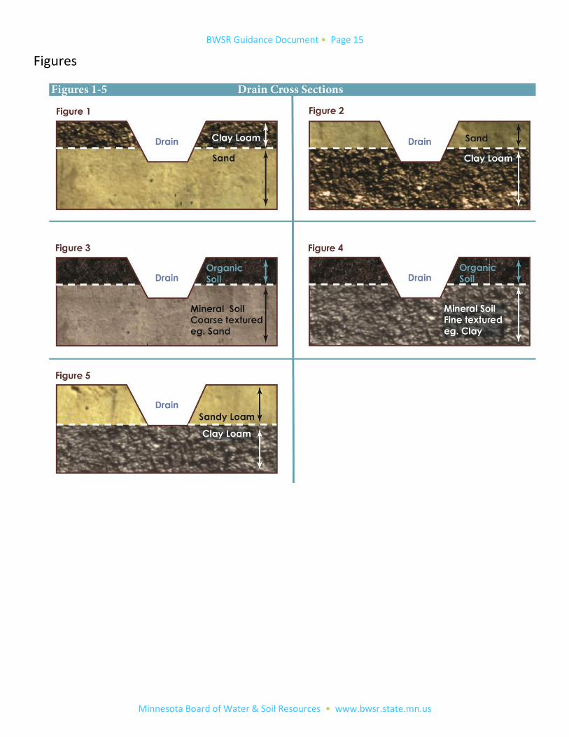
Type of vegetation in vicinity of drain. This considers rooting depth, plant phenology and water requirements. Depth of drain with respect to a barrier. Organic soil over sand is a barrier. Downward movement of water will
be limited. Examples of barriers can be found on Figures 1-5. The duration and intensity of evapotranspiration. Effectiveness of the drain at maintaining a lowered water table. Precipitation.
3 See Regional Supplements to the Corps of Engineers Wetland Delineation Manual, especially Chapter 5
BWSR Guidance Document • Page 5
Minnesota Board of Water & Soil Resources • www.bwsr.state.mn.us
5. Drainage setback tables, their use and limitations
5a. Tables Minnesota setback tables are available through the Minnesota NRCS Technical Resources Website. A link is provided below. The tables are county-specific, have a date of issuance, and include user notes. NRCS specifically states on user notes that the setback distances are only for the situation where a drainage system will be installed and the landowner wishes to avoid impacting wetland hydrology. The tables are subject to change so users should refer to the NRCS Website for current information. Minnesota NRCS uses “setback distance” rather than lateral effect. These terms are not interchangeable. In the judgment of NRCS staff, the setback distance is the minimum distance, in feet, from the wetland boundary to the centerline of the tile line or to the toe of the ditch bank for drainage ditches necessary to minimize adverse hydrologic impacts to adjacent wetlands.
Notes:
The fact sheet and worksheet that accompany the tables provide information about USDA wetland policy that may not be applicable to the Wetland Conservation Act or Federal Clean Water Act.
Although NRCS developed the tables for implementation of the wetland provisions of the Farm Bill Program (“Swampbuster”), the tables were developed using soils and hydrology criteria consistent with the Regional Supplements.
Minnesota Setback Tables are available on the MN NRCS website or http://www.nrcs.usda.gov/wps/portal/nrcs/detail/mn/technical/?cid=nrcs142p2_023711
5b. How to use the tables Instructions for using Setback Tables:
1. Determine if wetland hydrology indicators are present. As stated on page 4, evidence of wetland hydrology
overrules an estimate by a drainage equation that wetland hydrology has been eliminated.
2. Overlay drain(s) on a soil map. 3. Determine average depth of drain per dominant soil type. (To determine dominant soil type, the mapping unit
description should be reviewed.) Round average ditch depth to the nearest foot. 4. Determine setback distance for each soil type (step 2) from the NRCS tables. 5. If the drain crosses more than one soil type, compute a weighted average setback.4 6. Delineate a setback corridor for the drain(s). 7. Identify wetlands within and adjacent to the setback corridor. 8. Consider the setback distance and proximity of wetlands to the drain in the context of an overall assessment of
wetland hydrology, including the source and direction of water supply to the wetland(s). The setback estimate should be compared to how much site conditions vary from underlying assumptions and the complexity of the site. A review of part 5c is suggested. As a reminder, the setback number is but one piece of information. If site conditions vary greatly from the assumptions, greater reliance should be made of other data.
4 The setback distance is weighted by the length of the drain through each soil type. There are situations where the setback distance (measured perpendicular to the wetland edge) encompasses two or more soils. In this case, the contribution of each soil to the drainage effect must be computed. See Appendix 1 for instructions.
BWSR Guidance Document • Page 6
Minnesota Board of Water & Soil Resources • www.bwsr.state.mn.us
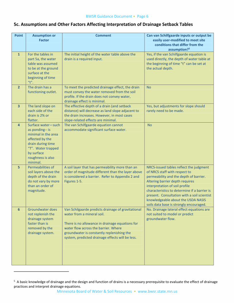
5c. Assumptions and Other Factors Affecting Interpretation of Drainage Setback Tables Point Assumption or
Factor Comment Can van Schilfgaarde inputs or output be
easily user-modified to meet site conditions that differ from the
assumption?5
1 For the tables in part 5a, the water table was assumed to be at the ground surface at the beginning of time “t”.
The initial height of the water table above the drain is a required input.
Yes, if the van Schilfgaarde equation is used directly, the depth of water table at the beginning of time “t” can be set at the actual depth.
2 The drain has a functioning outlet.
To meet the predicted drainage effect, the drain must convey the water removed from the soil profile. If the drain does not convey water, drainage effect is minimal.
No
3 The land slope on each side of the drain is 2% or flatter.
The effective depth of a drain (and setback distance) will decrease as land slope adjacent to the drain increases. However, in most cases slope-related effects are minimal.
Yes, but adjustments for slope should rarely need to be made.
4 Surface water—such as ponding-- is minimal in the area affected by the drain during time “T”. Water trapped by surface roughness is also minimal.
The van Schilfgaarde equation cannot accommodate significant surface water.
No
5 Permeabilities of soil layers above the depth of the drain do not vary by more than an order of magnitude.
A soil layer that has permeability more than an order of magnitude different than the layer above is considered a barrier. Refer to Appendix 2 and Figures 1-5.
NRCS-issued tables reflect the judgment of NRCS staff with respect to permeability and the depth of barrier. Altering barrier depth requires interpretation of soil profile characteristics to determine if a barrier is present. Consultation with a soil scientist knowledgeable about the USDA NASIS soils data base is strongly encouraged.
6 Groundwater does not replenish the drainage system faster than is removed by the drainage system.
Van Schilgaarde predicts drainage of gravitational water from a mineral soil. There is no allowance in drainage equations for water flow across the barrier. Where groundwater is constantly replenishing the system, predicted drainage effects will be less.
No. Drainage lateral effect equations are not suited to model or predict groundwater flow.
5 A basic knowledge of drainage and the design and function of drains is a necessary prerequisite to evaluate the effect of drainage practices and interpret drainage equations.
BWSR Guidance Document • Page 7
Minnesota Board of Water & Soil Resources • www.bwsr.state.mn.us
Point Assumption or Factor
Comment Can van Schilfgaarde inputs or output be easily user-modified to meet site
conditions that differ from the assumption?5
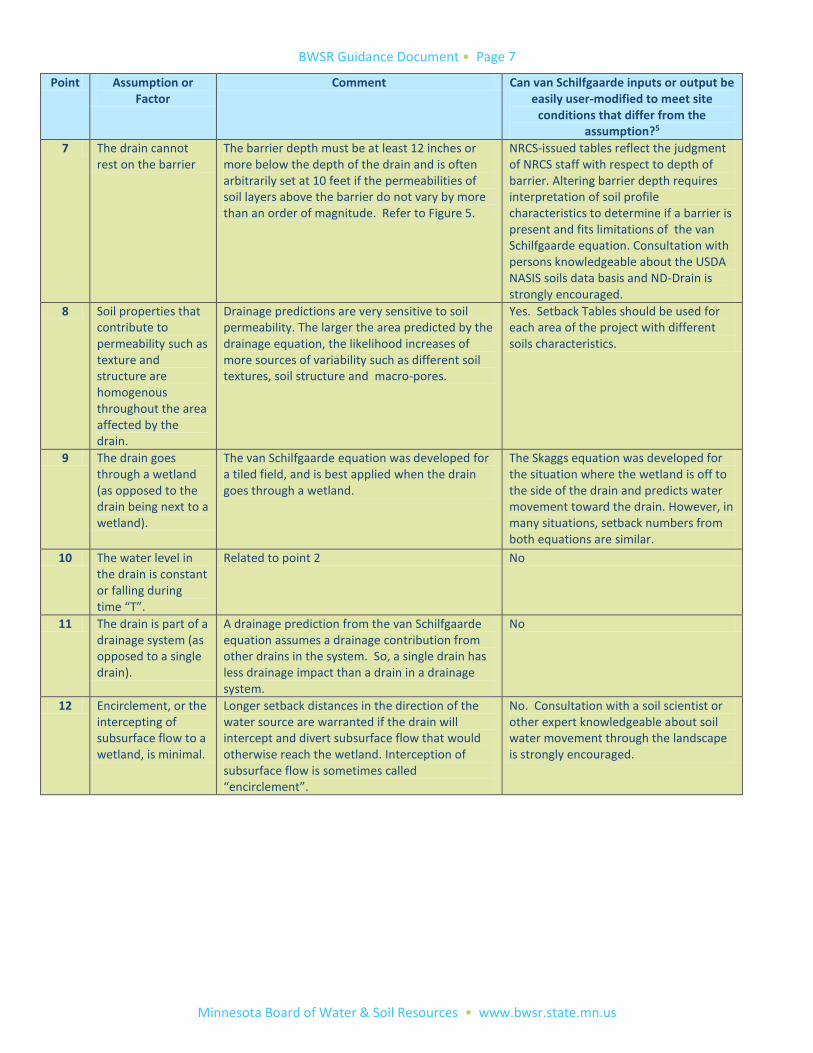
7 The drain cannot rest on the barrier
The barrier depth must be at least 12 inches or more below the depth of the drain and is often arbitrarily set at 10 feet if the permeabilities of soil layers above the barrier do not vary by more than an order of magnitude. Refer to Figure 5.
NRCS-issued tables reflect the judgment of NRCS staff with respect to depth of barrier. Altering barrier depth requires interpretation of soil profile characteristics to determine if a barrier is present and fits limitations of the van Schilfgaarde equation. Consultation with persons knowledgeable about the USDA NASIS soils data basis and ND-Drain is strongly encouraged.
8 Soil properties that contribute to permeability such as texture and structure are homogenous throughout the area affected by the drain.
Drainage predictions are very sensitive to soil permeability. The larger the area predicted by the drainage equation, the likelihood increases of more sources of variability such as different soil textures, soil structure and macro-pores.
Yes. Setback Tables should be used for each area of the project with different soils characteristics.
9 The drain goes through a wetland (as opposed to the drain being next to a wetland).
The van Schilfgaarde equation was developed for a tiled field, and is best applied when the drain goes through a wetland.
The Skaggs equation was developed for the situation where the wetland is off to the side of the drain and predicts water movement toward the drain. However, in many situations, setback numbers from both equations are similar.
10 The water level in the drain is constant or falling during time “T”.
Related to point 2 No
11 The drain is part of a drainage system (as opposed to a single drain).
A drainage prediction from the van Schilfgaarde equation assumes a drainage contribution from other drains in the system. So, a single drain has less drainage impact than a drain in a drainage system.
No
12 Encirclement, or the intercepting of subsurface flow to a wetland, is minimal.
Longer setback distances in the direction of the water source are warranted if the drain will intercept and divert subsurface flow that would otherwise reach the wetland. Interception of subsurface flow is sometimes called “encirclement”.
No. Consultation with a soil scientist or other expert knowledgeable about soil water movement through the landscape is strongly encouraged.
BWSR Guidance Document • Page 8
Minnesota Board of Water & Soil Resources • www.bwsr.state.mn.us
Point Assumption or Factor
Comment Can van Schilfgaarde inputs or output be easily user-modified to meet site
conditions that differ from the assumption?5
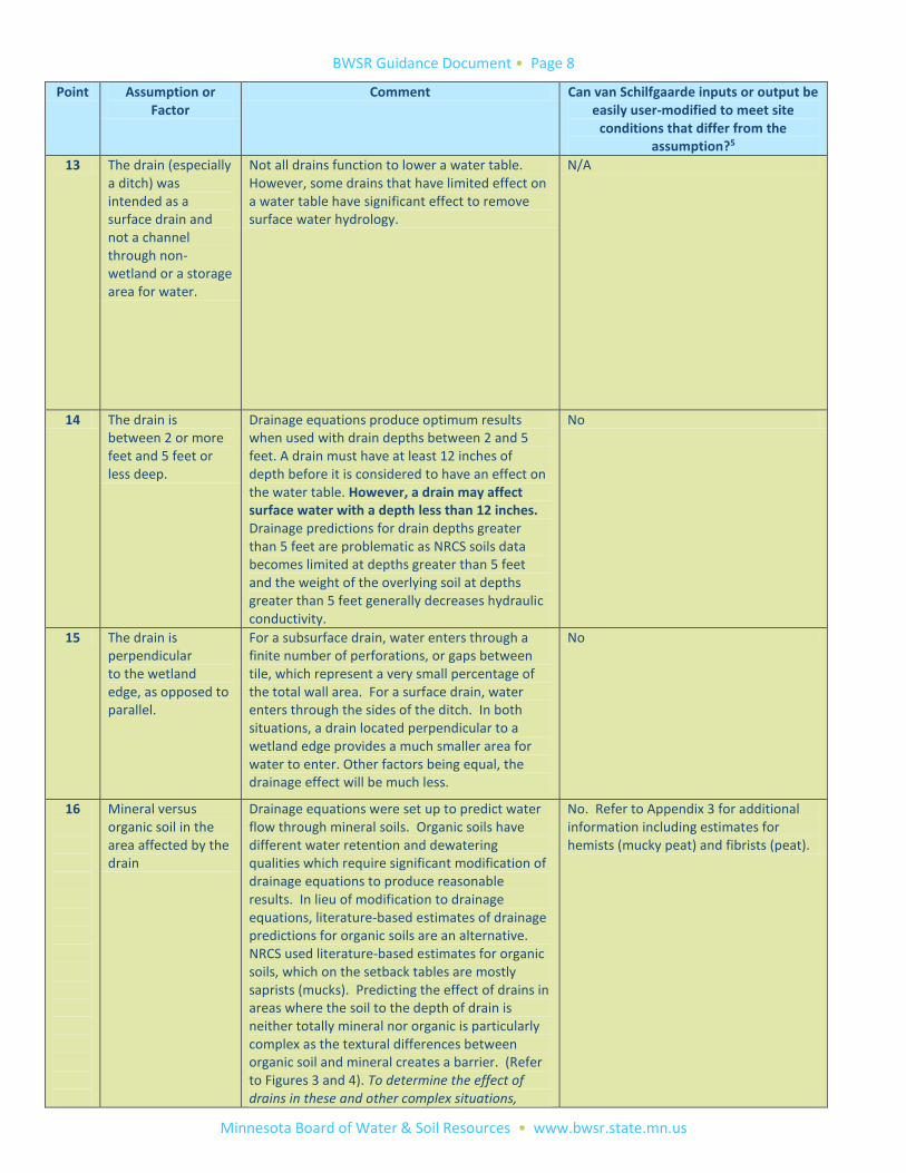
13 The drain (especially a ditch) was intended as a surface drain and not a channel through non-wetland or a storage area for water.
Not all drains function to lower a water table. However, some drains that have limited effect on a water table have significant effect to remove surface water hydrology.
N/A
14 The drain is between 2 or more feet and 5 feet or less deep.
Drainage equations produce optimum results when used with drain depths between 2 and 5 feet. A drain must have at least 12 inches of depth before it is considered to have an effect on the water table. However, a drain may affect surface water with a depth less than 12 inches. Drainage predictions for drain depths greater than 5 feet are problematic as NRCS soils data becomes limited at depths greater than 5 feet and the weight of the overlying soil at depths greater than 5 feet generally decreases hydraulic conductivity.
No
15 The drain is perpendicular to the wetland edge, as opposed to parallel.
For a subsurface drain, water enters through a finite number of perforations, or gaps between tile, which represent a very small percentage of the total wall area. For a surface drain, water enters through the sides of the ditch. In both situations, a drain located perpendicular to a wetland edge provides a much smaller area for water to enter. Other factors being equal, the drainage effect will be much less.
No
16
Mineral versus organic soil in the area affected by the drain
Drainage equations were set up to predict water flow through mineral soils. Organic soils have different water retention and dewatering qualities which require significant modification of drainage equations to produce reasonable results. In lieu of modification to drainage equations, literature-based estimates of drainage predictions for organic soils are an alternative. NRCS used literature-based estimates for organic soils, which on the setback tables are mostly saprists (mucks). Predicting the effect of drains in areas where the soil to the depth of drain is neither totally mineral nor organic is particularly complex as the textural differences between organic soil and mineral creates a barrier. (Refer to Figures 3 and 4). To determine the effect of drains in these and other complex situations,
No. Refer to Appendix 3 for additional information including estimates for hemists (mucky peat) and fibrists (peat).
BWSR Guidance Document • Page 9
Minnesota Board of Water & Soil Resources • www.bwsr.state.mn.us
Point Assumption or Factor
Comment Can van Schilfgaarde inputs or output be easily user-modified to meet site
conditions that differ from the assumption?5
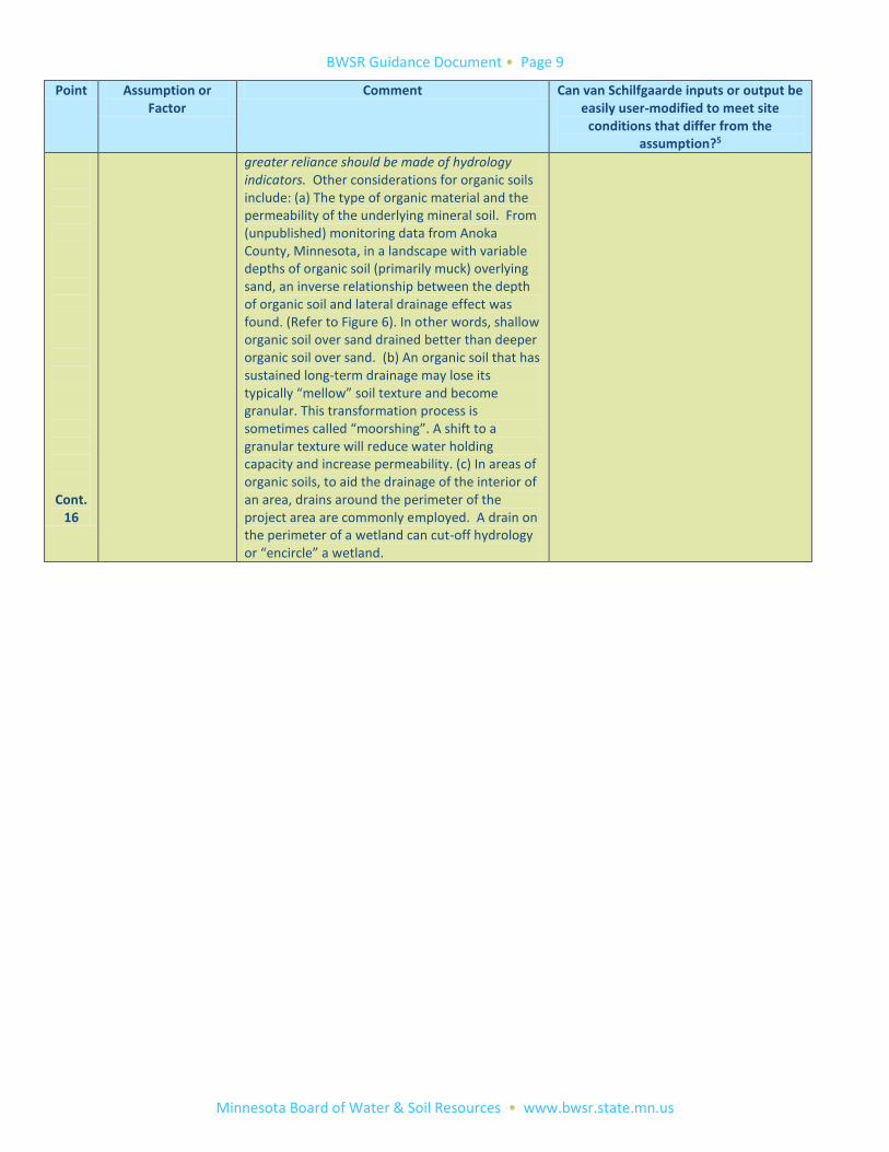
Cont. 16
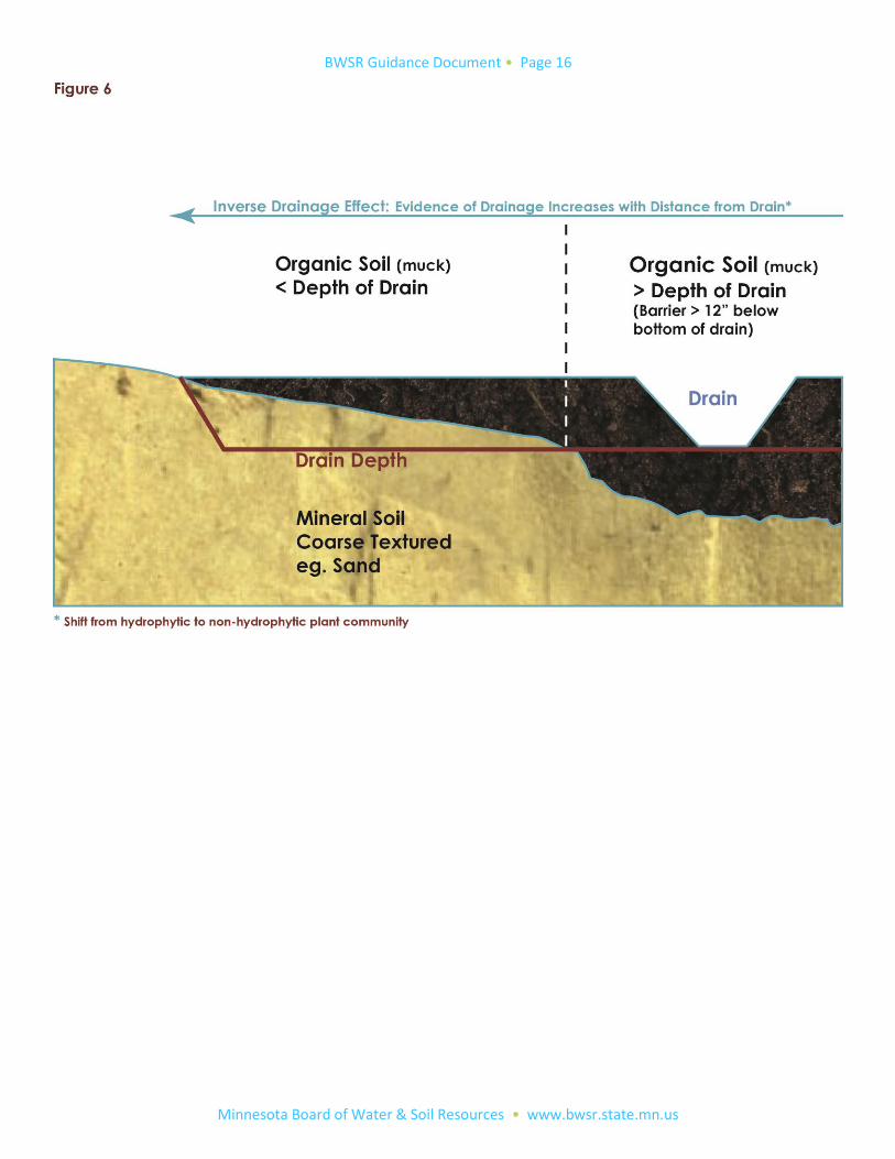
greater reliance should be made of hydrology indicators. Other considerations for organic soils include: (a) The type of organic material and the permeability of the underlying mineral soil. From (unpublished) monitoring data from Anoka County, Minnesota, in a landscape with variable depths of organic soil (primarily muck) overlying sand, an inverse relationship between the depth of organic soil and lateral drainage effect was found. (Refer to Figure 6). In other words, shallow organic soil over sand drained better than deeper organic soil over sand. (b) An organic soil that has sustained long-term drainage may lose its typically “mellow” soil texture and become granular. This transformation process is sometimes called “moorshing”. A shift to a granular texture will reduce water holding capacity and increase permeability. (c) In areas of organic soils, to aid the drainage of the interior of an area, drains around the perimeter of the project area are commonly employed. A drain on the perimeter of a wetland can cut-off hydrology or “encircle” a wetland.

BWSR Guidance Document • Page 10
Minnesota Board of Water & Soil Resources • www.bwsr.state.mn.us
Acknowledgements Appreciation is given to staff of the Natural Resources Conservation Service in Minnesota and Wisconsin, especially Sonia Jacobsen (retired) and Annette Humpal, respectively, for their assistance in developing this guidance. Duration This guidance is effective October, 2013 and will remain in effect until revised. Comments and suggestions BWSR is soliciting comments and suggestions to this version. This guidance and other wetland technical information are
posted on the BWSR Website at http://www.bwsr.state.mn.us/wetlands/delineation/Drainage_setback_guidance.pdf
Comments and suggestions may be submitted to Megan Lennon at [email protected]
BWSR Guidance Document • Page 11
Minnesota Board of Water & Soil Resources • www.bwsr.state.mn.us
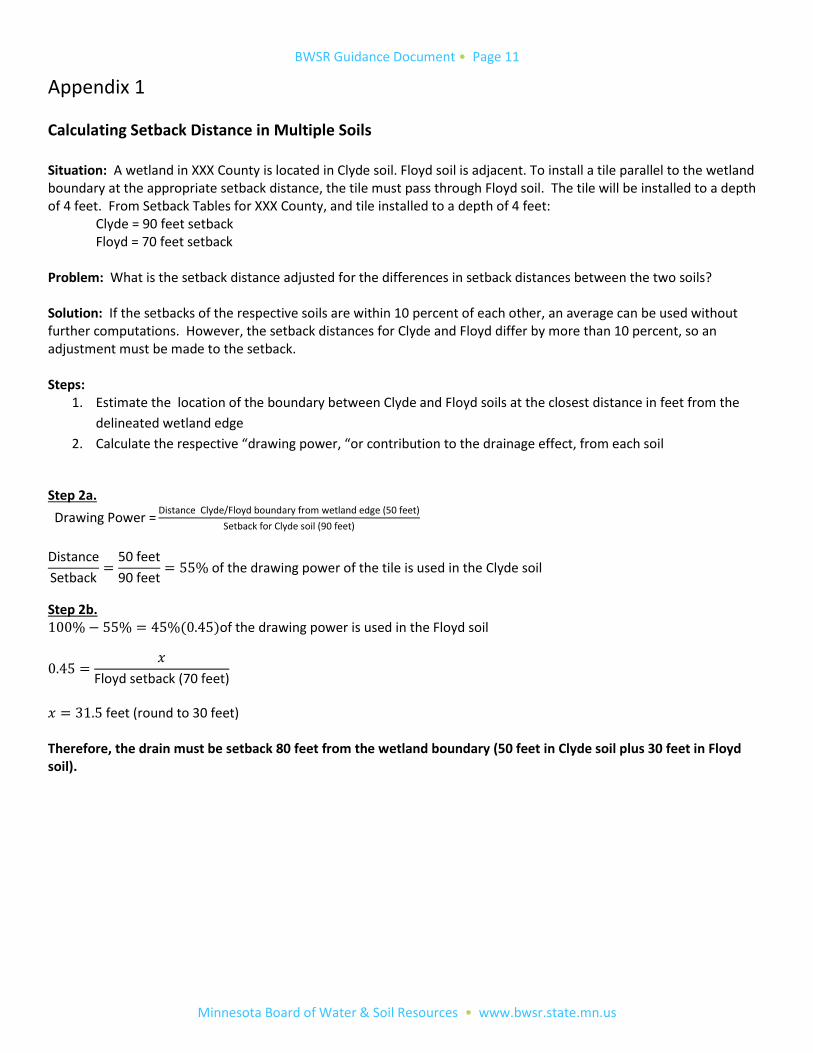
Appendix 1
Calculating Setback Distance in Multiple Soils Situation: A wetland in XXX County is located in Clyde soil. Floyd soil is adjacent. To install a tile parallel to the wetland boundary at the appropriate setback distance, the tile must pass through Floyd soil. The tile will be installed to a depth of 4 feet. From Setback Tables for XXX County, and tile installed to a depth of 4 feet: Clyde = 90 feet setback Floyd = 70 feet setback Problem: What is the setback distance adjusted for the differences in setback distances between the two soils? Solution: If the setbacks of the respective soils are within 10 percent of each other, an average can be used without further computations. However, the setback distances for Clyde and Floyd differ by more than 10 percent, so an adjustment must be made to the setback. Steps:
1. Estimate the location of the boundary between Clyde and Floyd soils at the closest distance in feet from the
delineated wetland edge
2. Calculate the respective “drawing power, “or contribution to the drainage effect, from each soil
Step 2a.
Drawing Power =Distance Clyde/Floyd boundary from wetland edge (50 feet)
Setback for Clyde soil (90 feet)
Distance
Setback=
50 feet
90 feet= 55% of the drawing power of the tile is used in the Clyde soil
Step 2b. 100% − 55% = 45%(0.45)of the drawing power is used in the Floyd soil
0.45 =𝑥
Floyd setback (70 feet)
𝑥 = 31.5 feet (round to 30 feet) Therefore, the drain must be setback 80 feet from the wetland boundary (50 feet in Clyde soil plus 30 feet in Floyd soil).
BWSR Guidance Document • Page 12
Minnesota Board of Water & Soil Resources • www.bwsr.state.mn.us
Appendix 2
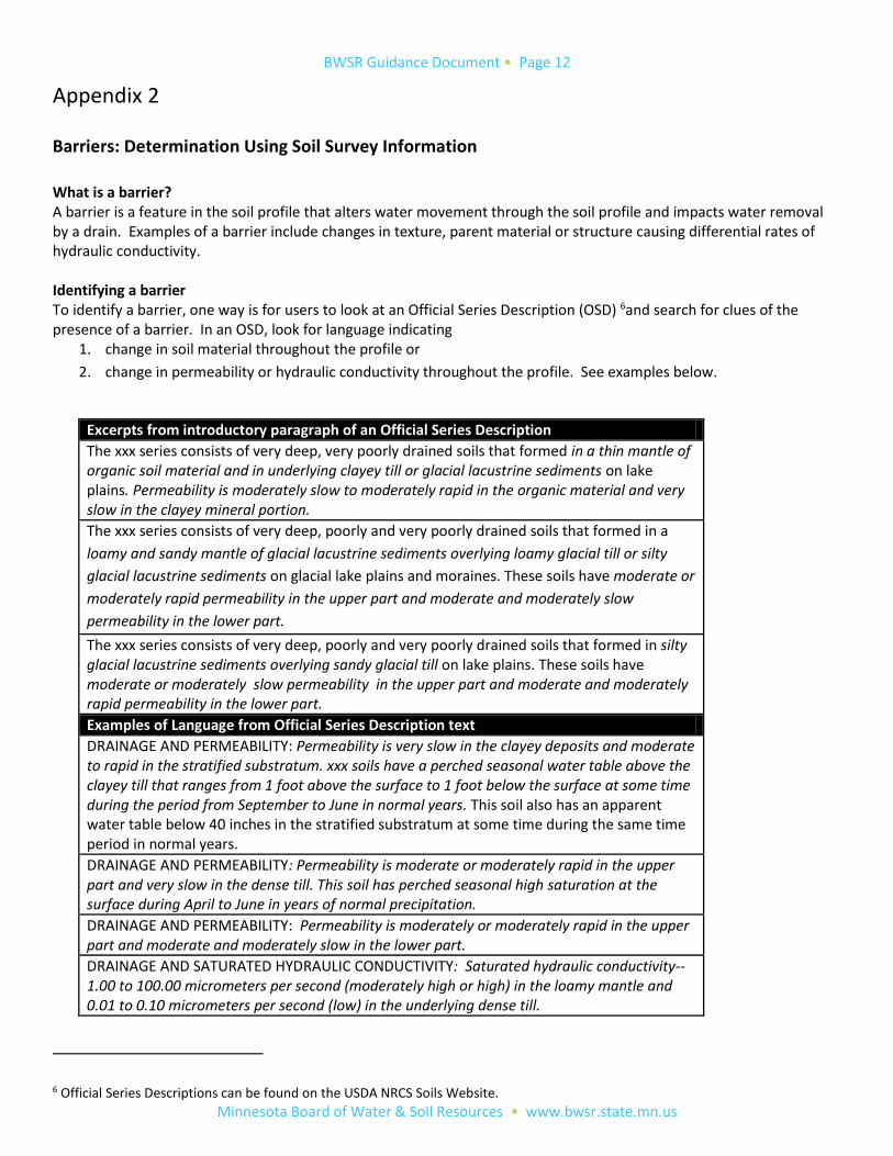
Barriers: Determination Using Soil Survey Information
What is a barrier? A barrier is a feature in the soil profile that alters water movement through the soil profile and impacts water removal by a drain. Examples of a barrier include changes in texture, parent material or structure causing differential rates of hydraulic conductivity. Identifying a barrier To identify a barrier, one way is for users to look at an Official Series Description (OSD) 6and search for clues of the presence of a barrier. In an OSD, look for language indicating
1. change in soil material throughout the profile or
2. change in permeability or hydraulic conductivity throughout the profile. See examples below.
Excerpts from introductory paragraph of an Official Series Description
The xxx series consists of very deep, very poorly drained soils that formed in a thin mantle of organic soil material and in underlying clayey till or glacial lacustrine sediments on lake plains. Permeability is moderately slow to moderately rapid in the organic material and very slow in the clayey mineral portion.
The xxx series consists of very deep, poorly and very poorly drained soils that formed in a
loamy and sandy mantle of glacial lacustrine sediments overlying loamy glacial till or silty
glacial lacustrine sediments on glacial lake plains and moraines. These soils have moderate or
moderately rapid permeability in the upper part and moderate and moderately slow
permeability in the lower part.
The xxx series consists of very deep, poorly and very poorly drained soils that formed in silty glacial lacustrine sediments overlying sandy glacial till on lake plains. These soils have moderate or moderately slow permeability in the upper part and moderate and moderately rapid permeability in the lower part.
Examples of Language from Official Series Description text
DRAINAGE AND PERMEABILITY: Permeability is very slow in the clayey deposits and moderate to rapid in the stratified substratum. xxx soils have a perched seasonal water table above the clayey till that ranges from 1 foot above the surface to 1 foot below the surface at some time during the period from September to June in normal years. This soil also has an apparent water table below 40 inches in the stratified substratum at some time during the same time period in normal years.
DRAINAGE AND PERMEABILITY: Permeability is moderate or moderately rapid in the upper part and very slow in the dense till. This soil has perched seasonal high saturation at the surface during April to June in years of normal precipitation.
DRAINAGE AND PERMEABILITY: Permeability is moderately or moderately rapid in the upper part and moderate and moderately slow in the lower part.
DRAINAGE AND SATURATED HYDRAULIC CONDUCTIVITY: Saturated hydraulic conductivity--1.00 to 100.00 micrometers per second (moderately high or high) in the loamy mantle and 0.01 to 0.10 micrometers per second (low) in the underlying dense till.
6 Official Series Descriptions can be found on the USDA NRCS Soils Website.
BWSR Guidance Document • Page 13
Minnesota Board of Water & Soil Resources • www.bwsr.state.mn.us
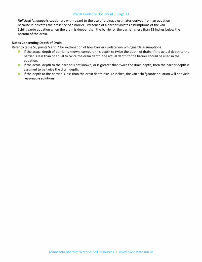
Italicized language is cautionary with regard to the use of drainage estimates derived from an equation because it indicates the presence of a barrier. Presence of a barrier violates assumptions of the van Schilfgaarde equation when the drain is deeper than the barrier or the barrier is less than 12 inches below the bottom of the drain.
Notes Concerning Depth of Drain Refer to table 5c, points 5 and 7 for explanation of how barriers violate van Schilfgaarde assumptions.
If the actual depth of barrier is known, compare this depth to twice the depth of drain. If the actual depth to the barrier is less than or equal to twice the drain depth, the actual depth to the barrier should be used in the equation.
If the actual depth to the barrier is not known, or is greater than twice the drain depth, then the barrier depth is assumed to be twice the drain depth.
If the depth to the barrier is less than the drain depth plus 12 inches, the van Schilfgaarde equation will not yield reasonable solutions.
BWSR Guidance Document • Page 14
Minnesota Board of Water & Soil Resources • www.bwsr.state.mn.us
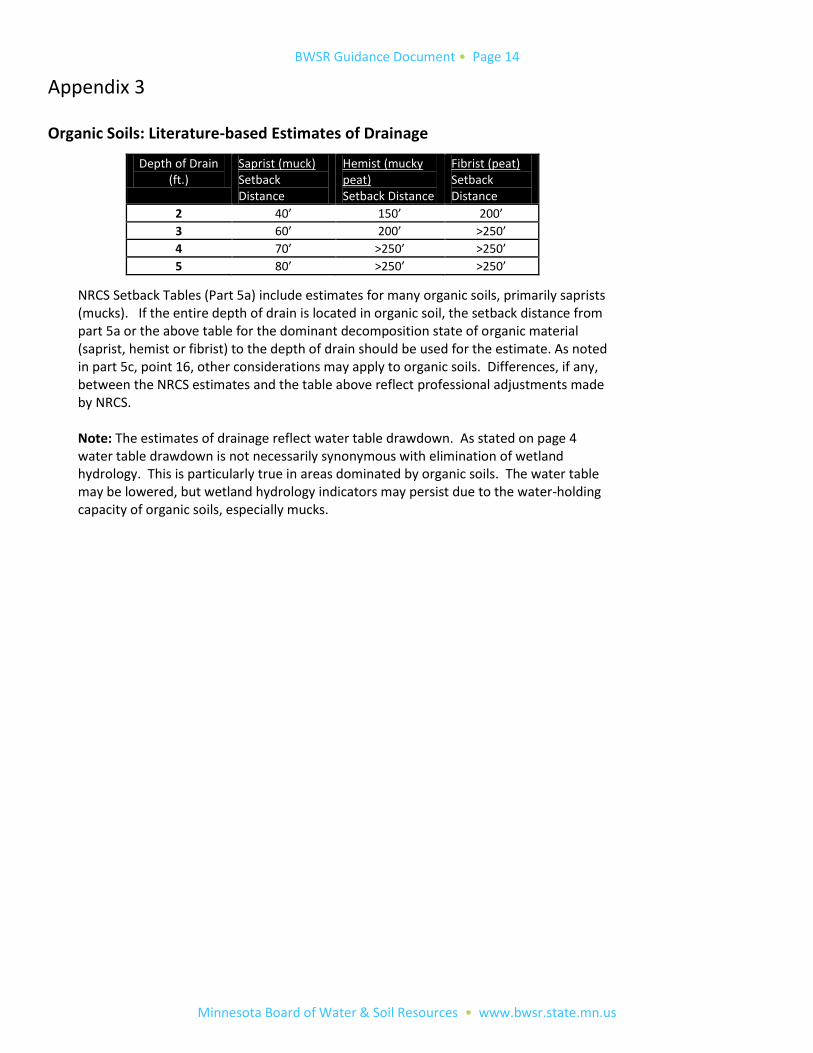
Appendix 3 Organic Soils: Literature-based Estimates of Drainage
NRCS Setback Tables (Part 5a) include estimates for many organic soils, primarily saprists (mucks). If the entire depth of drain is located in organic soil, the setback distance from part 5a or the above table for the dominant decomposition state of organic material (saprist, hemist or fibrist) to the depth of drain should be used for the estimate. As noted in part 5c, point 16, other considerations may apply to organic soils. Differences, if any, between the NRCS estimates and the table above reflect professional adjustments made by NRCS.
Note: The estimates of drainage reflect water table drawdown. As stated on page 4 water table drawdown is not necessarily synonymous with elimination of wetland hydrology. This is particularly true in areas dominated by organic soils. The water table may be lowered, but wetland hydrology indicators may persist due to the water-holding capacity of organic soils, especially mucks.
Depth of Drain (ft.)
Saprist (muck) Setback Distance
Hemist (mucky peat) Setback Distance
Fibrist (peat) Setback Distance
2 40’ 150’ 200’
3 60’ 200’ >250’
4 70’ >250’ >250’
5 80’ >250’ >250’
BWSR Guidance Document • Page 15
Minnesota Board of Water & Soil Resources • www.bwsr.state.mn.us
Figures
BWSR Guidance Document • Page 16
Minnesota Board of Water & Soil Resources • www.bwsr.state.mn.us
BWSR Guidance Document • Page 17
Minnesota Board of Water & Soil Resources • www.bwsr.state.mn.us
References
1. Armstrong, A. and D. Castle. 1999. Drainage of Organic Soils. In Agricultural Drainage, Skaggs, R.W. and J. van Schilfgaarde, editors; Agronomy Series 38, American Society of Agronomy. pp 1083-1105
2. Arndt, J. and E.S. Verry. 2008. Guidance for Scope and Effect and Hydrology (well) Studies to Support Wetland Delineations in Minnesota and the Upper Midwest. Project supported by the Minnesota Board of Water and Soil Resources, Saint Paul, Minnesota and the U.S. Army Corps of Engineers, Saint Paul District
3. Boelter, D. and E.S. Verry. 1977. Peatland and Water in the Northern Lake States. U.S. Forest Service Technical
Report NC-31
4. Boelter, D. 1972. Water Table Drawdown around an Open Ditch in Organic Soils. Journal of Hydrology (15),pp. 329-340
5. Braekke, F.H. 1983. Water Table Levels at Different Drainage Densities on Deep Peat in Northern Norway. Forest Ecology and Management (5), pp. 169-192
6. Brandyk, T., J. Szatylowicz, R. Oleszczuk and T. Gnatowski. 2002. Water-Related Physical Attributes of Organic
Soils. In Organic Soils and Peat Materials for Sustainable Agriculture. CRC Press. pp. 33-66
7. Franzmeier, D.P., W.D. Hosteter and R.E. Roeske. 2001. Drainage and Wet Soil Management: Drainage Recommendations for Indiana Soils. Purdue University Extension Bulletin AY-300
8. Fuchsman, C.H. 1986. The Peat-Water Problem: Reflections, Perspectives, Recommendations. In Peat and Water. Elsevier Applied Science Publishers, pp. 331-360
9. Gawlik, J. 1998. The Influence of the Moorshing Process of Peats on Changes of Their Water Capacity Caused by Thermal Drying. Polish Journal of Soil Science 31(2): 15-21
10. Jacobsen, S.M.M and R.W. Skaggs. 1997. Lateral Effect: What’s Known and Unknown. ASAE Paper 97-2034.
Presented at ASAE Meeting, Minneapolis, Minnesota. American Society of Agricultural Engineers
11. Kolka, R.K. ,S.D. Sebestyen, E.S. Verry and K.N. Brooks. 2011. Physical Properties of Organic Soils. In Peatland
Biochemistry and Watershed Hydrology at the Marcell Experimental Forest. CRC Press pp. 135-176
12. Leete, J.H and J.R. Frischman. 2000. Geology and Hydrogeologic Setting of the Hugo (Minnesota) Area. Internal
memorandum, Minnesota Department of Natural Resources , Division of Waters
13. Naber, J., B. Emmons and S. Grubb. 2005. Comparative Analysis of Methodologies Used to Predict Wetland
Impacts Resulting from a Repair of Anoka Ditch 53-62 in Blaine, Minnesota. Memorandum to U.S. Corps of Engineers, Saint Paul District
14. Powell, K., J. Peterson, E. Mohring, J. Naber and G. Larson. 2009. Lateral Effect Training Seminar. Wetland
Delineator Certification Program. University of Minnesota
BWSR Guidance Document • Page 18
Minnesota Board of Water & Soil Resources • www.bwsr.state.mn.us
15. Sands, Gary. 2001. Soil Water Concepts. University of Minnesota Extension Bulletin BU-07644-GO
16. Skaggs, R.W., G.M. Chescheir and B.D. Phillips. 2005. Methods to Determine Lateral Effect of a Drainage Ditch on
Wetland Hydrology. Transactions of the ASAE Vol. 48(2):577-584
17. Stuyt, L.C.P.M, W. Dierickx and J. Martinez Beltran. 2005. Materials for Subsurface Land Drainage Systems. Water flow into and inside the drain. Pages 43-62. Food and Agriculture Organization (FAO) of the United Nations. Rome.
18. University of Illinois. 2011. Illinois Drainage Guide
19. U.S. Army Corps of Engineers. 2012. Regional Supplement to the Corps of Engineers Wetland Delineation
Manual: Northcentral and Northeast Region (Version 2.0)
20. U.S. Army Corps of Engineers. 2010. Regional Supplement to the Corps of Engineers Wetland Delineation
Manual: Midwest Region (Version 2.0)
21. U.S. Army Corps of Engineers. 2010. Regional Supplement to the Corps of Engineers Wetland Delineation
Manual: Great Plains Region (Version 2.0)
22. U.S. Army Engineer Research and Development Center (ERDC). 2006. C. V. Noble and C.Talbot, co-authors.
Review of Ditch Scope and Effect Modeling and MnRAM Analysis used to Support the Village Meadows Comprehensive Wetland Management Plan (Anoka County, Minnesota)
23. U.S. Army Corps of Engineers. 2005. Technical Standard for Water Table Monitoring of Potential Wetland Sites. Technical Note ERDC TN-WRAP-05-02
24. USDA NRCS. 2011. Hydrology Tools for Wetland Determination. Minnesota Supplement to the National
Engineering Handbook. Part 650. Engineering Field Handbook. Chapter 19
25. USDA NRCS. 2011. Scope and Effect Equations. Wisconsin EFH Notice 210-WI-121
26. USDA NRCS. 2010. Scope and Effect Determinations. NFSAM, Fifth Edition, Part 516.10
27. USDA NRCS. 2008. Drainage of Organic Soils. In Drainage of Agricultural Land, National Engineering Handbook, Section 16
28. USDA NRCS. 1998. Scope and Effect Equations for Evaluating the Removal of Soil Saturation for Wetland
Hydrology Determination: Supporting Documentation for Scope and Effect Internet Site. P.B.Rodrigue
29. Woodward, D.E. and A.G. Warne. 1997. Results of Verification Studies on Methods to Determine the Hydrology
of Potential Wetland Sites. Proceedings of the conference on management of landscapes disturbed by channel incision, 1997. Wang, S.S.Y., E.J. Langendoen, and F.D. Shields, Jr.