BWM 08 adj - cr.indianrailways.gov.in
173
CENTRAL RAILWAY BLOCK WORKING MANUAL 2008 P R E F A C E This Manual contains detailed instructions regarding block working on single line, double line and triple line sections of this Railway. The instructions contained in this Manual have to be read in conjunction with the General and Subsidiary Rules Book and nothing contained in this Manual will be treated as modifying or amending the General and Subsidiary Rules. A copy of this Manual is to be kept at all stations and block cabins and all staff connected with the operation of block instruments shall make themselves thoroughly conversant with the instructions contained in this manual. Amendments to this Manual will be issued in the form of correction slips. It is the responsibility of the staff to whom this Manual is issued to keep it duly corrected. Suggestions for improving the contents of this Manual should be addressed to the 'Chief Operations Manager'. Vinay Mittal May, 2008 Chief Operations Manager Central Railway, Chatrapati Shivaji Terminus, Mumbai-400001
Transcript of BWM 08 adj - cr.indianrailways.gov.in

CENTRAL RAILWAY
BLOCK WORKING MANUAL
2008
P R E F A C E
This Manual contains detailed instructions regarding block
working on single line, double line and triple line sections of this
Railway. The instructions contained in this Manual have to be read in
conjunction with the General and Subsidiary Rules Book and nothing
contained in this Manual will be treated as modifying or amending the
General and Subsidiary Rules.
A copy of this Manual is to be kept at all stations and block
cabins and all staff connected with the operation of block instruments
shall make themselves thoroughly conversant with the instructions
contained in this manual. Amendments to this Manual will be issued
in the form of correction slips. It is the responsibility of the staff to
whom this Manual is issued to keep it duly corrected.
Suggestions for improving the contents of this Manual should
be addressed to the 'Chief Operations Manager'.
Vinay Mittal
May, 2008 Chief Operations Manager Central Railway, Chatrapati Shivaji Terminus, Mumbai-400001

- 1 -
BLOCK WORKING MANUAL
CHAPTER - I
GENERAL INSTRUCTIONS
Para Page
1.01 Issue of Block Working Manual
1.02 Knowledge of Rules
1.03 Addenda and Corrigenda
1.04 System of Working
1.05 Object of Electrical Block Instruments
1.06 Fixed, Hand and Fog and Flair Signals
1.07 Double Line Methods.
1.08 Block Instruments with Lock (Double Line)
1.09 Block Instruments Single Line
1.10 Station Master
1.11 Use of Instruments
1.12 Training of Staff
1.13 Certificate of Proficiency
1.14 Working of Block Instruments
1.15 Extra Care during repairs to Line Wires
1.16 Entry into Cabins
1.17 Stations
CHAPTER II
THE ABSOLUTE BLOCK SYSTEM
2.01 Essentials of the Absolute Block System
2.02 Essentials of the Lock & Block System
2.03 Conditions for granting Line Clear at different classes of Block stations
2.04 Obstruction on Double Line at a block station when a train is approaching
2.05 Obstruction on Single Line at a block station when a train is approaching
2.06 Obstruction in the block section at a Class 'A' station on double line
2.07 Obstruction in the block section at a class 'B' station on double line
2.08 Obstruction in the block section at a Class 'A' station on single line
2.09 Obstruction in the block section at a class 'B' station on single line
equipped with Two Aspect Lower Quadrant Signal
2.10 Obstruction outside the First Stop signal at a Class 'B' station on single line.
2.11 Procedure for Blocking back and Obstruction removed signal on Double line

- 2 -
2.12 Procedure for blocking forward
CHAPTER III
USE OF ELECTRICAL INSTRUMENTS ON DOUBLE LINE
GENERAL PROVISIONS
3.01 Means of granting or obtaining Line Clear
3.02 Provision of Instruments
3.03 Description of block instruments - Double line
3.04 Authority to proceed
3.05 Lock on last Stop signal
CHAPTER IV
CODE OF BELL SIGNALS AND MODE OF SIGNALLING
TRAINS ON DOUBLE LINE BLOCK INSTRUMENTS
4.01 Bell Code Double Line
4.02 Acknowledgement of signals
4.03 Maintenance of Train Signal Register
4.04 Call Attention and / or Attend Telephone
4.05 'Attend Telephone' signal
4.06 Sending of 'Is Line Clear' signal
4.07 Acceptance of the 'Is Line Clear' signal and sending of a 'Line Clear' signal
4.08 Mode of signalling train on Block Instruments
4.09 Train stopping in section
4.10 'Stop and Examine Train' and ‘Train passed without Tail lamp/board’ signal.
4.11 The 'Train divided' signal
4.12 Procedure for despatching assisting train in obstructed block section
and clearing the same
4.13 Refusal of the 'Is Line Clear' signal
4.14 'Obstruction Danger signal'
4.15 'Train Entering Section' signal
4.16 'Train Out of section' signal
4.17 Precautions before giving the 'Train Out of Section' signal
4.18 'Cancel last signal' signal Double line
4.19 'Testing' signal
4.20 Failure of block instruments
CHAPTER V
BLOCK WORKING ON THE SINGLE LINE
5.01 Means of granting or obtaining line clear
5.02 Provision of instruments

- 3 -
5.03 Neal's Token Block Instrument- Description of
5.04 Neal's Ball Token Block Instrument 'A' type- Description of
5.05 Neal's Tablet Block Instrument - Description of
5.06 Intermediate siding Instrument single Type
5.07 Intermediate siding Instrument Multiple Type
5.08 Working into and out of siding situated between two Block stations
- with Tokenless Block Instruments
5.09 Locking of last Stop signals with Neal's Block Instruments
5.10 Token transfer of
5.11 Token loss of
5.12 General requirements of tokenless block instruments -
Handle type and Push Button type
5.13 Daido's tokenless single line block instruments
5.14 Kyosan's tokenless single line block instrument ( Handle type)
5.15 Podanur/IRS tokenless single line block instrument (Push button type)
CHAPTER VI
CODE OF BELL SIGNALS AND MODE OF SIGNALLING TRAINS
ON THE SINGLE LINE BLOCK INSTRUMENTS
6.01 Bell Code Single line
6.02 Acknowledgement of signals
6.03 'Attention' signal
6.04 The 'Is Line Clear' signals when to be sent
6.05 Acceptance of the 'Is Line Clear' signal and sending of a 'Line Clear' signal
6.06 Mode of signalling trains on various block instruments on single line
6.07 Train stopping in section 'Is Line Clear' signal for (Refer Para 4.09)
6.08 Refusal of the 'Is Line Clear' signal and sending of the 'Obstruction Danger' signal
6.09 The 'Train Entering Section' Signal
6.10 'Train out of section' signal'
6.11 'Cancel last signal' signal (single line)
6.12 Normalising the block instruments when train returns from
block section to the despatching block station
6.13 Testing signal
CHAPTER VII
WORKING OF TRAINS AT BLOCK STATIONS AT WHICH
ELECTRICAL BLOCK INSTRUMENTS ARE NOT PROVIDED

- 4 -
7.01 Transmission of signals
7.02 Train Signal Register
7.03 Mode of signalling trains on electrical communication instruments
7.04 Line Clear Refusal of
7.05 Train stopping in section
7.06 Engine in rear of train and coupled light engine
7.07 'IN' Report
7.08 'Obstruction Danger' Message
7.09 'Stop and Examine Train' message
7.10 Failure of Electrical communication instrument
7.11 Denoting numbers of the line clear Enquiry and Reply message Book
7.12 Line Clear messages, description of trains in
7.13 Numbering of Line Clear Messages
7.14 Private Numbers
7.15 Writing and signing of Line Clear Inquiry and Reply message book and
Paper Line Clear Ticket
7.16 Labelling of Line Clear Inquiry and Reply message Book
7.17 Cancellation of Line Clear Enquiry
7.18 When two trains from opposite direction cross at a station
CHAPTER VIII
POINTS AFFECTING MOVEMENT OF TRAINS AND PROCEDURE
FOR EXCHANGE OF LINE AND SIGNAL BADGES AT
INTERLOCKED AND NON INTERLOCKED STATIONS
8.01 Points affecting the movement of trains
8.02 Line Number Badges
8.03 Non-interlocked stations, Procedure for reception and despatch of trains
8.04 Crossing of trains at station on single line section
CHAPTER IX
CONDITIONS FOR TAKING 'OFF' HOME SINGAL AND PROCEDURE
FOR ADMISSION OF TRAINS
9.01 Conditions for taking 'off' Home signal
9.02 Signals taking 'off' for the reception of train at
interlocked and non-interlocked stations
9.03 Isolation of Running Line and Diagram
CHAPTER X

- 5 -
AUTHORITY TO PROCEED HOW GIVEN AND STATION MASTERS
RESPONSIBILITIES AS TO TOKEN / LINE CLEAR TICKET AND
BLOCK INSTRUMENTS
10.01 Authority to proceed
10.02 Handing over token by Driver to Guard of the train in Block section
10.03 Pouches and Hoops for exchanging tokens
10.04 Token or Line Clear Ticket for non stopping trains
10.05 Token number to be recorded
10.06 Special responsibility of Station Master as to electrical
token instruments and to the token
10.07 Line Clear Tickets
10.08 Responsibility of Station Master as to authority to proceed
10.09 Authority to proceed when to be delivered to the Driver stopping at station
10.10 Issue of Private Numbers
10.11 The specimens of Enquiry and Line Clear Ticket and Reply Book
10.12 Failure of block instruments
10.13 Measures of rectify defective instruments
10.14 Abnormal conditions of tokenless block instruments
10.15 Failure of single line tokenless instruments
10.16 Failure of communication on telephone on single line sections,
where tokenless instruments are provided
CHAPTER XI
SIGNALS AND POINTS
11.01 Signal, slot and Light Repeaters
11.02 Protection and working of points of outlaying sidings
11.03 Signals Working of
11.04 Points and signals at interlocked stations, electrical control of
11.05 Station Masters control at interlocked stations
provided with double wire signalling
CHAPTER XII
PRIVATE NUMBERS AND TRAIN SIGNAL REGISTER
12.01 Private Numbers issue of
12.02 Private Number sheets
12.03 Train Signal Register

- 6 -
CHAPTER XIII
PANEL WORKING
(A) Panel Interlocking
13.01 Panel & Panel interlocking
13.02 Panel Diagram
13.03 Colour code of buttons
13.04 The sequence of buttons for the various operations
13.05 Panel Indications
13.06 Button checking indications and prolonged operation of button indicator
13.07 Cancellation of a route already set
13.08 Cancellation of overlap
13.09 Recording of the readings of the counters
13.10 Manual operation of Motor points
13.11 General Instructions
13.12 Safe working practices
(B)Route Relay Interlocking
13.13 Route Relay Interlocking
13.14 Relay Room
13.15 Precautions for effective functioning of Relay Rooms
CHAPTER XIV
BLOCK PROVING AXLE COUNTER WORKING
14.01 Block Proving Axle Counter
14.02 Description of the Indications /features on the Axle Counter Indication
Cum Reset Box
14.03 Custody of Keys
14.04 Reset Button
14.05 Counters for Recording Reset Operation
14.06 Indications
14.07 Complete arrival of train
14.08 Resetting Procedure of Axle Counter
14.09 Failure of Axle Counter
14.10 Working of trolley/Motor trolley/Lorry etc.
14.11 Shunting
CHAPTER XV
THE AUTOMATIC BLOCK SYSTEM
15.01 Essentials of Automatic Block System on Double line
15.02 Failures of Signals in Automatic section

- 7 -
15.03 Procedure during Failure of Automatic signalling
APPENDIX - I
Specimen of forms used in connection with train working.
���� ����

CHAPTER I GENERAL INSTRUCTIONS
- 1 -
CHAPTER I
GENERAL INSTRUCTIONS 1.01 Issue of Block Working Manual-This book of rules and regulations for working trains
on Double & Single Line by means of Electrical Instruments on the ABSOLUTE BLOCK SYSTEM shall be issued to all staff concerned as directed by the Chief Operations Manager, Central Railway.
1.02 Knowledge of Rules--Every Railway Servant supplied with this book must make him /
her self thoroughly acquainted with the rules pertaining to his / her duties, and he / she will be held responsible for the knowledge of and compliance with all the rules that concern him. Nothing in this book shall be accepted as modifying or amending the General and Subsidiary Rules, in conjunction with which, this book should be carefully studied.
1.03 Addenda and Corrigenda—All alterations or corrections that may from time to time be
notified, shall be neatly posted and shall be recorded on the pages provided for the purpose.
1.04 System of Working—The Absolute Block system is in force on the Central Railway
except the following sections where Automatic Block System and One Train Only System in force.
(a) The Automatic Block System is in force on the following sections:
(i) MUMBAI DIVISION
CSTM- Kalyan, Kalyan- Neral, Kalyan- Titwala, Thane –Vashi and CSTM – Panvel/Andehri (Harbour line). (ii) BHUSAWAL DIVISION
Bhusawal- Jalgaon
Note : The sections where Automatic signaling system is in force is shown in the Working Time Table of the Division concerned, which may be updated time to time.
(b) The One Train only System -
The sections where One Train only System is in force is shown in the Working Time table of the Division concerned.
1.05 Object of Electrical Block Instruments-
(a) The object of signalling trains by electrical block instruments is to provide at all times a visual indication of the block sections to which they refer and to guard against two trains being admitted into a block section at the same time.
(b) Each instrument is connected to a similar instrument at the next block station and the two block instruments work together. The pair of instruments is used for

CHAPTER I GENERAL INSTRUCTIONS
- 2 -
working both Up & Dn Trains over the block section so that each is used both for sending train to the next station or for receiving train from the next station. Each station controls the line by which trains approach it, and the line by which trains leave, it is controlled from the station at the other end of the block section.
1.06 Fixed, Hand, Fog and Flare signals-
Signalling trains by electrical block instruments does not in any way do away with the use of fixed, hand, fog and flare signals, whenever and wherever such signals may be required.
1.07 Double Line Methods- There are two kinds of block instruments in use for working:-
Block instruments with lock, and
Block instruments without lock.
1.08 Block instruments with Lock ( Double Line ) - These instruments in addition to giving visual indication of the state of the block sections to which they refer are provided with locking which prevents the block instruments to be brought to ‘Line Closed’ position unless the train to be received has cleared the section clearing track circuit or the axle counter. The following block instruments with locks are in use on Central Railway –
i. SGE Lock & Block instruments. ii. SGE Lock & Block Instrument with BPAC.
1.09 Block instruments ( Single Line) - The following block instruments are used on the single line –
i) Neale’s Ball Token Instruments ii) Neale’s Tablet Instrument iii) Daido’s Single Line Tokenless Block Instruments. iv) Kyosan’s Single Line Tokenless Block Instruments v) Podanur/IRS Type Single Line Tokenless Block Instruments.( Push Button type)
1.10 Station Master – means the person on duty who is for the time being responsible for
the working of the traffic within station limits and includes any person who is for the time being in independent charge of the working of any signal & responsible for the working of trains under the system of working in force vide G.R. 1.02 (53).
1.11 Use of Instruments - Block Instruments shall only be operated by the Station Master/
ASM/Cabin ASM/Switchman on duty and shall be used exclusively for the purpose of signalling trains strictly in accordance with the rules & regulations laid down. Every train in its progress from one block station to another shall be signaled on the block instruments.

CHAPTER I GENERAL INSTRUCTIONS
- 3 -
Station staff must not interfere with any part of a block instrument when it is out of order, or at any other time. Block instrument cases must be kept free of dust, grease, etc. and no article must be placed on the Block Instrument and battery boxes.
1.12 Training of Staff – When the block instruments are in actual use for train working, they shall not be used for the purpose of imparting training to staff.
1.13 Certificate of proficiency – No person shall operate block instruments for train working unless he/she has passed the requisite competency examination and holds a valid certificate of competency. ( T.115-B )
Note : See G.R. 5.01 and SR 5.01-3 1.14 Working of Block Instruments – The bell plunger shall be pressed to the full extent
with a slight pause between each stroke otherwise the signals on the bell will be indistinct or lost.
1.15 Extra care during repairs to Line wires – Whenever the person in charge of
Government Telegraph Department working party intends to work at a station or in block section, he shall advice the ‘Test Room’ indicating the section or station where work is to be carried out. This information should be conveyed by the Test Room to the Section Controller concerned, giving the name of the person in charge of the working party and the exact kilometreage where the work will be undertaken. The section controller on receipt of this advice shall intimate the station concerned. On completion of the work by Govt. Telegraph department working party, the information in writing should be given to the section controller by the Test Room canceling previous message.
In the event of interruption when such an advice is not possible or on non -controlled sections, the person in charge of the working party should intimate in writing the station master of the station concerned. The Station Master during the period of repairs to the line wires shall work with extra care and vigilance.
On receipt of such advice the station master shall advice the station at the other end of the block section to exercise care and vigilance during the period of repair work is in progress.
1.16 Entry into Cabins – Entry of unauthorized persons into cabins (whether railway servants or otherwise) is strictly prohibited. No railway servant shall enter in any cabin except when required to do so in connection with his / her regular duties.
1.17 Station – Whenever used, the word ‘Station’ shall mean either a block station or a block cabin.
Block stations are those at which the Loco Pilot must obtain an authority to proceed under the system of working to enter the block section with his train. Block stations

CHAPTER I GENERAL INSTRUCTIONS
- 4 -
includes Class ‘A’, ‘B’, ‘C’, and ‘Special Class’. The rules contained in this manual are applicable to all these stations.
See- G.R. – 1.03.
���� ����

CHAPTER II ABSOLUTE BLOCK SYSTEM
- 5 -
CHAPTER II
THE ABSOLUTE BLOCK SYSTEM
2.01 ESSENTIALS OF THE ABSOLUTE BLOCK SYSTEM (See GR 8.01)
(1) Where trains are worked on the Absolute Block System a) No train shall be allowed to leave a block station unless line clear has been
received from the block station in advance, and b) On double lines such line clear shall not be given unless the line is clear not
only up to the first stop signal at block station at which such line clear is given but also for an adequate distance beyond it;
c) On single line such line clear shall not be given unless line is clear of trains running in the same direction, not only up to the first stop signal at the block station at which such line clear is given, but also for an adequate distance beyond it, and is clear of trains running in the direction towards the block station to which such line clear is given.
(2) Unless otherwise directed by approved special instructions, the adequate distance referred to in clauses (b) & (c) of sub-rule (1) shall not be less than –
a) 400 Meters in case of two-aspect lower quadrant signalling, and b) 180 meters in case of multiple-aspect signalling
NOTE –That level crossing gates within a station yard are open for road traffic across
the line does not affect giving of ‘Line Clear’ for a train to approach such a station but before any signal is taken ‘off’ to admit a train, all such gates should be closed and adequately secured.
2.02 Essentials of the Lock and Block System – The following are the essentials of the
Lock & Block system –
It shall not be possible to take ‘off ‘the last stop signal to permit a train to leave a block station until ‘Line Clear’ has been received from the block station in advance.
The entry of a train into the block section shall cause the last stop signal to automatically return to ‘on’ position.
‘Line Clear’ shall not be given by the block station in advance until the preceding train has passed over the section clearing track circuit or its equivalent and until stop signal/signals in rear of the train has / have been replaced to ‘on ‘ position.
2.03 Conditions for granting ‘Line Clear’ at different classes of block stations –
Class ‘A’ station - (see also G.R. 8.02)
At a class ‘A’ station, the line shall not be considered clear and Line Clear shall not be given, unless –

CHAPTER II ABSOLUTE BLOCK SYSTEM
- 6 -
a) The whole of the last preceding train has arrived complete; b) All relevant signals have been put back to ‘ON’ behind the said train; c) The line on which it is intended to receive the incoming train is clear up to the
starter; and d) All points have been correctly set and all facing points have been locked for the
admission of the train on the said line.
Class ‘B’ station - (see also G.R. 8.03)
(1) ON DOUBLE LINE
The line shall not be considered clear and Line Clear shall not be given, unless
a) The whole of the last preceding train has arrived complete; b) All relevant signals have been put back to ‘ON’ behind the said train; c) The line is clear –
i) At stations equipped with two aspect lower quadrant signalling - up to the Home signal or
ii) At stations equipped with multiple aspect upper quadrant signalling and multiple aspect colour light signalling – up to the outermost facing point or the block section limit board (if any).
(2) ON SINGLE LINE
The line shall not be considered clear and Line Clear shall not be given, unless-
(a) The whole of the last preceding train has arrived complete;
(b) All necessary signals have been put back to ‘ON’ behind the said train; and
(c) The line is clear –
i) At stations equipped with two aspect lower quadrant signaling- up to the Shunting Limit board or Advanced Starter (if any) at that end of the station nearest to the expected train, or
up to the Home Signal if there is no Shunting Limit board or Advanced Starter, or
up to the outermost facing points if there is no Shunting Limit board or Advanced Starter or Home Signal,
ii) At a stations equipped with multiple aspect signalling – up to the Shunting Limit board or Advanced Starter (if any) at the end of the station nearest to the expected train, or
upto the outermost facing points if there is no Shunting Limit Board or Advanced Starter.

CHAPTER II ABSOLUTE BLOCK SYSTEM
- 7 -
Note - At a class ‘B’ single line station, this rule does not forbid direct reception of a train from one side, when Line Clear has been given to the block station on other side provided the distance between the Outer signal and outermost facing point in two aspect lower quadrant signalling, and between the Home signal and outermost facing points in multiple aspect signalling is not less than the sum total of the adequate distances prescribed in GR 8.01 in regard to conditions for granting Line Clear and GR 3.40 in regard to conditions for taking ‘off’ Home signal for the admission of the train even where Shunting Limit Boards or Advanced Starters have not been provided as prescribed in sub-rule (I) of GR 3.32.
Class ‘C’ station – (see GR 8.04)
At a class ‘C’ station on Single line or Double line in two aspect lower quadrant signalling or multiple aspect signalling, the line shall not be considered clear and line clear shall not be given, unless –
a) the whole of the last preceding train has passed complete at least 400 metres beyond the Home signal and is continuing its journey; and
b) all relevant signals taken ‘off’ for the preceding train have been put back to ‘ON’ behind the said train;
Provided that on a single line the line is also clear of trains running in the opposite direction towards the block hut from the block station at the other end.
2.04 Obstruction on Double line at a Block station when a train is approaching -
(1) Class ‘A’ station - When Line Clear has been given, no obstruction shall be permitted outside the Home signal, or on the line on which it is intended to admit the train, upto the starter pertaining to the said line.
(2) Class ‘B’ station - When Line Clear has been given, no obstruction shall be permitted outside the station section but shunting within the station section may go on continuously, provided the necessary signals are kept at ‘ON’.
(3) When signals have been taken ‘Off’ for an approaching train on a line which is not isolated, no shunting movement shall be carried on towards the points over which the incoming train will pass.
Note - See GR 8.05 and SR 5.13-1(d) also. 2.05 Obstruction on single line at a block station when a train is approaching -
Class ‘B’ station -
(i) The line outside the Home signal in two aspect lower quadrant signalling territory or outermost facing points in multiple aspect signalling territory in the direction of a train for which line clear has been given shall only be obstructed when a Shunting Limit board or an Advanced Starter is provided and under special instructions which take in to consideration the speed, weight and brake power of trains, the

CHAPTER II ABSOLUTE BLOCK SYSTEM
- 8 -
gradients, the position of the first stop signal and the distance from which that signal can be seen by the Loco Pilot of an approaching train.
(ii) If the necessary Signals are kept at ’ON’ shunting may be carried on within station section, provided the provisions of GR 8.09 are complied with for shunting upto Shunting Limit Board or Advanced Starter where provided.
(iii) When signals have been taken ‘off’ for an incoming train on to a line which is not isolated, no shunting movement shall be carried on towards the points over which the incoming train will pass.
Note – See GR 8.09, 8.10 and SR 5.14-2, SR 8.10-1.
2.06 Obstruction in the Block Section at a class ‘A’ station on Double Line – (a) Obstruction in rear of the starter when block section is clear –
When the block section in rear is clear, if it becomes necessary to obstruct the line outside the Home signal or between the Home signal and the Starter signal, the line shall be blocked back.
Note – See GR 8.06-(2).
(b) Obstruction outside the last stop signal when block section in advance is clear –
If, when the block section in advance is clear, it becomes necessary to obstruct the line outside the last stop signal –
(i) the line shall be blocked forward. ( for procedure refer Para 2.12 of this Manual )
(ii) either a Shunting arm ( which may for this purpose be provided on the post of last stop signal ) shall be taken ‘off’ or a written permission to shunt on the prescribed form (T/806) shall be given to the Loco Pilot. Note – See GR 8.06-(3).
(c) Obstruction when block section is occupied by train traveling away from the station –
If the block section is occupied by a train travelling away from the block station at which shunting operations have to be performed, such shunting shall be permitted behind the train under special instructions taking into considerations the speed, weight & brake power of the trains and the gradients on the section, and as soon as intimation has been received that the train has arrived at the block station in advance the line shall be blocked forward if it still obstructed by the shunting train.
To enter in block section the Loco Pilot shall be authorised either by taking ‘off’ Shunt signal provided below last stop signal (if any) or by issuing T/806 with endorsement “Shunting behind a train travelling away”.
Note : See para (3) of G.R. 8.06 & clause (a) or (c) of G.R. 8.15.

CHAPTER II ABSOLUTE BLOCK SYSTEM
- 9 -
2.07 Obstruction in the block section at a class ‘B’ stations on double line -
(a) Obstruction outside home signal at a station equipped with two aspect lower quadrant signal when block section is clear
When the block section in rear is clear and if it becomes necessary to obstruct the line outside the Home Signal equipped with two aspect lower quadrant signals, the line should be blocked back, following the procedure laid down in BWM 2.11 (i) and an authority on form T/806 shall be issued to the Loco Pilot of the train.
(b) Obstruction outside the outermost facing points or the ‘block section limit board’ where provided, at station equipped with multiple aspect signal when block section in rear is clear -
When the block section in rear is clear, if it becomes necessary to obstruct the line outside the outer most facing points or the ‘Block Section Limit Boards’, where provided, the line should be blocked back, in accordance with procedure laid down in para 2.11 (i) and an authority on form T/806 shall be issued to the Loco Pilot of the train.
(c) Obstruction outside the last stop signal when block section in advance is clear
When the block section in advance is clear, if it becomes necessary to obstruct the line outside the Last Stop signal –
(i) the line shall be blocked forward, in accordance with procedure laid down in para 2.12.
(ii) either a Shunt signal ( which may for this purpose be provided below the last stop signal ) shall be taken ‘off’ or a written permission to shunt on form T/806 shall be given to the Loco Pilot.
2.08 Obstruction in the Block Section at a class ‘A’ station on single line –
On Central Railway there is no class ‘A’ station on single line. 2.09 (1) Obstruction in the block section at a class ‘B’ station on single line equipped
with two aspect lower quadrant signal (See G.R.8.11 and S.R. 8.11-1 also) –
(a) AT STATIONS WHERE TOKEN BLOCK INSTRUMENTS ARE INSTALLED -
The line out side the station section and up to the Outer signal shall not be obstructed unless a railway servant specially appointed in this behalf by the Station Master is in charge of the operation, and unless -
the block section in to which the shunting is to take place is clear of an approaching train and all relevant and necessary signals are in ‘On’ position .
In the event of receipt of ‘Is line clear’ signals from the other end of the section, and if the section is still occupied, the line should be Immediately’ blocked back’.
CHAPTER II ABSOLUTE BLOCK SYSTEM
- 10 -
(b) AT STATIONS WHERE TOKENLESS BLOCK INSTRUMENTS ARE INSTALLED -
Shunting outside the station section between the outer signals shall be performed only after the line has been blocked back and the shunt / occupation key or T/806 handed over to the Loco Pilot.
Note : To perform shunting up to the Outer signal without block back T/806 is to be issued with endorsement “ You are authorized to perform shunting up to the Outer signal”.
(2) Obstruction in the block section at a class ‘B’ station on single line equipped
with Multiple aspect signal (See G.R. 8.12 and S.R. 8.12-1 also) –
(a) At stations where token block instruments are installed
Shunting may be performed between the home signals without blocking back the section, provided line clear has not been granted for a train to approach.
In the event of receipt of ‘Is line clear’ signals from the other end of the section, and if the section is still occupied, the line should be Immediately’ blocked back’.
(b) At stations where token less block instruments are installed – Shunting outside the station section between the home signal shall be performed only after the line has been blocked back and the shunt /occupation key or T806(b) handed over to the Loco Pilot.
Note : To perform shunting up to the Home signal without block back T/806 is to be issued with endorsement “ You are authorized to perform shunting up to the Home signal”.
2.10 Obstruction outside the first stop signal at a class ‘B’ station on single line
The line outside the first stop signal shall not be obstructed unless the section has been ‘blocked back’.
2.11 (1) Procedure for ‘BLOCKING BACK’ & ‘OBSTRUCTION REMOVED’ SIGNAL ON THE
DOUBLE LINE -
The Station Master who intends to block back the line shall ask the Station Master of the station in rear on the telephone for permission to ‘block back’, who will acknowledge the message and grant permission supported by a Private Number.
Following procedure is to be adopted on different block instruments.
S.G.E. Three Position Lock & Block Instrument –
Shunting being performed at Station 'A'. Block instrument at Station 'A' and Station 'B' indicates 'Line Closed' position
Station 'A' Station 'B'

CHAPTER II ABSOLUTE BLOCK SYSTEM
- 11 -
1. Gives 'Call Attention' signal 2. Acknowledges
3. Gives 'Attend Telephone' signal 4. Acknowledges and 'Attend Telephone'
5. Informs intention to perform shunting in rear block section
6. Acknowledges and gives consent with support of Private Number
7. Repeats Private Number for confirmation and record it in TSR .
-
8. Gives 'Call Attention ' signal 9. Acknowledges
10. Gives three beats and turn the commutator directly towards the 'Train on Line' position
11. Acknowledges
12. Issue T/806 (quoting Private Number received ) to the Loco Pilot
-
13. When the shunting movement has cleared the block section
14. Gives 'Call Attention' signal 15. Acknowledges
16. Gives ‘Block back Clear’/ 'Obstruction removed' signal with four beats and on the last beat turn commutator directly to 'Line Closed' position
17. Acknowledges
Note: A Tail Lamp / Tail Board must be placed on the rearmost vehicle (or on the Engine if there are no vehicle attached) on the side facing the station in rear in order to serve as an indication of the complete return of the train before the ‘ Obstruction Removed’ signal is given.
(2) ‘BLOCKING BACK’ SIGNAL ON THE SINGLE LINE –
Neale’s Instruments – The Station Master who intends to ‘block back’ the line, shall ask for permission to ‘block back’ on the block telephone from the station in rear who will acknowledge the message and grant permission supported by a private number. He/she shall, then give three beats to the station in rear and press the plunger on the last beat. The Station master in rear will turn the handle of the block instrument to the ‘Train coming from’ position and will then acknowledge the signal by three beats, pressing the plunger on the last beat. The station master, blocking back the line, will then turn his handle to the ‘Train Going To’ position, extract the ball token or tablet and give one beat.
The Station Master will keep the token in his / her personal custody under lock and key until the shunting has been completed. Entries of the blocking back the line will be made in the Train Signal Register.

CHAPTER II ABSOLUTE BLOCK SYSTEM
- 12 -
‘OBSTRUCTION REMOVED’ SIGNAL ON THE SINGLE LINE –
(a) Neale's Instrument: -
On completion of shunting, the ball token will be inserted in the block instrument and Station Master will turn the handle to ‘Line Closed’ position and will give ‘Cancel Last Signal’ with five beats and press the plunger on the last beat. The Station Master in rear will turn the handle to ‘Line Closed’ position and acknowledges the ‘Cancel Last signal’ signal with five beats.
(b) Neale’s A Type Instrument: -
On completion of shunting, the ball token will be inserted in the block instrument and Station Master will give five beats and press the plunger on the last beat. The Station Master in rear will turn the handle to ‘Line Closed’ position and acknowledges the ‘Cancel Last Signal’ signal with five beats, press the plunger on the last beat. The Station Master of the station concerned will turn the handle to ‘Line Closed’ position.
Note : Each bell code signal given on the above instruments for blocking back the line and its cancellation must be preceded by a ‘Call Attention’ signal.
(3) ‘Block-Back’ Signal on single line token less instruments-
(a) Diado’s Kyosan’s handle type instruments:-
Shunting being performed at Station ‘A’
Station 'A' Station 'B'
Block Instrument Handle in Line Closed postion
Block Instrument Handle in Line Closed postion
1. Insert SM’s KEY and turns.
2. Gives 'Call Attention ' signal 3. Acknowledges
4. Gives ‘Attend Telephone’ signal 5. Acknowledges
6. Informs intention to Shunt up to opposite First Stop signal
7. Acknowledges and gives consent giving a Pvt. No.
8. Takes out the Occupation key of concerned section Block Instrument which locks the line clear giving and taking mechanism.
9. Hands over the Occupation Key to the Loco Pilot.
10. Completes shunting.
11. Key is put back in the Block

CHAPTER II ABSOLUTE BLOCK SYSTEM
- 13 -
Instrument and turned.
12. Informs the SM of Station ‘B’ giving a Pvt. No.
13. Acknowledges giving a Pvt. No.
Note : Shunting up to Opposite First stop signal is prohibited at Stations provided with catch siding .
(b) Podanur/IRS type tokenless instruments (Push button type).
In sections with Podanur/IRS type tokenless Block Instrument (Push button type) provided the authority to Shunt upto Opposite first stop signal is the(Shunt Key). For this purpose, the block instrument must be in ‘Line Closed’ position and following procedure should be followed.
Shunting being performed at Station ‘A’
Station 'A' Station 'B'
Block Instrument in Line Closed postion Block Instrument in Line Closed postion
1. Inserts SM’s KEY and turns.
2. Gives 'Call Attention ' signal 3. Acknowledges
4. Gives ‘Attend Telephone’ signal 5. Acknowledges
6. Informs intention to Shunt up to opposite First Stop signal
7. Acknowledges and gives consent giving a Pvt. No.
8. Takes out the “Shunt key” of concerned section Block Instrument and Hands over the Shunt Key to the Loco pilot and takes out the Station Master’s key.
9. Loco pilot completes shunting and returns ‘Shunt Key’ to SM.
10. Inserts SM’s key in the Block Instrument and turns and replaces shunt key in the instrument.
11. Takes out the SM’s KEY.
12. Informs SM ‘B’ that Shunt KEY has been put back in the instrument and gives a Pvt. No.
13. Acknowledges giving a Pvt. No.
Note : Shunting up to Opposite First stop signal is prohibited at Stations provided with catch siding .

CHAPTER II ABSOLUTE BLOCK SYSTEM
- 14 -
2.12 (a) Procedure for ‘blocking forward’ –
The Station Master who intends to ‘block forward’ the line, shall advice the S.M. of the station in advance on the block telephone supporting the advice by giving Private Number and the procedure detailed below shall be followed–
S.G.E. Three Position Lock & Block Instrument – The Station Master will give three beats to the Block Station in advance. The station in advance will acknowledge it by 3 beats and on the last beat of the signal turn the commutator from ‘Line closed’ position to ‘Train On Line’ position direct without taking it to LC position.
(b) Procedure for Cancelling Block Forward
When the shunting operations have been brought inside the last stop signal the Station Master shall advice the S.M. in advance on Block Telephone giving a Private Number. This shall be acknowledged by the S.M. of the station in advance giving also a Private Number.
S.G.E. Lock and Block Instrument
The ‘Cancel Last signal’ must be given on the block instrument with five beats to the station in advance. The S.M. of the station in advance shall acknowledge the ‘Cancel Last Signal’ with five beats and on the last beat of the signal turn the commutator to ‘Line Closed’ position from ‘Train on Line’ position.
c) Shunting of the train for which Line Clear has been obtained in advance
If it is necessary to do shunting beyond the ‘Last Stop Signal’ in connection with a train for which line clear has been obtained from the station ahead the line need not be blocked forward however the SM concerned must be advised of the same. The Loco Pilot shall be given authority on Form T/806. to perform shunting beyond the last stop signal.
(d) Authority to enter in the block section for shunting purpose-
(i) At the stations where a shunt signal is provided below the ‘Last Stop Signal’ should be taken ‘off’.
(ii) At the stations where shunt signal is not provided below the ‘Last Stop Signal’ the S.M. will authorise the Loco Pilot to enter in the block section with his train for shunting purpose by issuing T/ 806.
Loco Pilot shall return T/ 806 to the Station Master for cancellation as soon as the shunting movements have been brought inside the ‘Last Stop Signal’.
���� ����

CHAPTER III BLOCK WORKING ON DOUBLE LINE
- 14 -
CHAPTER III
BLOCK WORKING ON DOUBLE LINE
3.01 Means of granting or obtaining Line Clear – 1. Every train shall, in it progress from one block station to another, be regulated by means
of any one of or a combination of the following – (a) Block Instruments; Track circuits or Axle Counters;
(b) Telephones attached to the Block Instruments; (c) Station to station fixed telephones wherever available;
(d) Fixed telephone such as Railway auto phones & BSNL/MTNL phones; (e) Control Telephone; (f) VHF sets under special instructions, but not as the sole means of communication on
sections where passenger trains run.
2. Where the running of a train from one station to another, is controlled by Track Circuits, the block section is track circuited throughout its length, and where controlled by Axle Counters, the block section is provided with Axle Counters at either end. The last stop signal at the block station in rear is so controlled that it cannot be taken ‘off’ unless the block section in advance is shown to be clear either by Track Circuits or by Axle Counters. Visual indicators are provided at each block station showing the condition of the block sections both in rear and in advance of the station. In case of Intermediate Block Post, visual indicators are provided only at the block station in rear.
3.02 Provision of Instruments –
1. Electrical communication instruments shall be provided at every station except at class ‘D’ stations where they may be provided under special instructions.
2. (a) The electrical block instruments, where provided, and electrical communication instruments at any station shall be of a type approved by the Commissioner of Railway Safety and shall not be brought into use in the first instance unless they have been passed by him.
(b) The person in-charge of the maintenance of electrical block instruments or electrical communication instruments shall not without the approval of the Commissioner of Railway Safety, permit substitution, of the instruments and installation brought in the first instance by any instrument or installation which does not satisfy the conditions prescribed in clause (a).
3 03. Description of block instruments - Double line.
S.G.E. THREE-POSITION LOCK AND BLOCK INSTRUMENT. –
(1) Description of the Instrument
The various parts of the block instruments, as marked in the diagram and their functions

CHAPTER III BLOCK WORKING ON DOUBLE LINE
- 15 -
are described below: -
(i) The part of the block instrument marked (A) is the Bell by which bell signals are received. Each bell in an office or cabin is of a different tone from any other in the same office or cabin.
(ii) The part of the block instrument marked (B) is the commutator which can be turned either to the left or to the right with the bell plunger pressed. When it is turned in this manner, the movement of the Needle in the Sending Indicator of the instrument, as also of the Receiving Indicator of the corresponding instrument at the adjoining block station in rear, takes place.
(iii) The part of the block instrument marked (C) is the bell plunger by which bell signals are sent. This bell plunger also acts as Commutator Release Plunger. To operate the Commutator, it is necessary to press the bell plunger.
(iv) The part of the block instrument marked (D) is the Receiving Indicator and is for the purpose of indicating the signal received from the station in advance. It has three indications 'Line Closed', 'Line Clear ' and 'Train on Line' and is fitted with a needle which may point to any of the three indications. The position of the needle of the receiving indicator can only be changed by the station in advance. In the normal position, the needle of the Receiving Indicator points to 'Line Closed' which signifies that Line Clear for a train has not been received from the station in advance. The indications of the Receiving Indicator at a station correspond with those of the Sending Indicator at the next block station in advance.
(v) The part of the block instrument marked (E) is the Sending Indicator, and is for the purpose of indicating the signals sent to the station in rear. It has three indications, 'Line Closed', 'Line Clear' and 'Train on Line', and is fitted with a needle which may point to any of the three indications. In the normal position, the needle of the Sending Indicator points to 'Line Closed' which signifies that Line Clear for a train has hot been granted to the station in rear. The indications of the Sending Indicator at a station correspond with those of the Receiving Indicator at the next block station in rear.
(vi) The part of the block instrument marked (F) is the SM's Key which is used for the locking the Commutator in 'Line Closed', Line Clear' and 'Train on Line' positions.
The Commutator must always be locked when the S.M. / CASM / Cabin Master deputed for block working, leaves the office and on the ‘Train on Line ‘ position during TSL working. Block instrument’s key must be in his / her personal custody to avoid operation by an unauthorised person. When changing duty this key must be handed to the reliever by the relieved SM/Cabin Master and a remark to that effect entered in the Train Signal Register.
The second key must be kept in a sealed envelope marked ‘Spare Key Block Instruments’ and locked in the station safe. It is to be used only when the other key has been lost or damaged in either of which case Signal Inspector, Divisional Railway Manager and Chief Operations Manager must be informed. The Police shall also be informed if either key is lost. The Signal Inspector will replace keys, which have been damaged or lost.

CHAPTER III BLOCK WORKING ON DOUBLE LINE
- 16 -
SGE LOCK & BLOCK INSTRUMENT DIAGRAM

CHAPTER III BLOCK WORKING ON DOUBLE LINE
- 17 -
(2) Some additional features of S.G.E. Three-Position Lock and Block instruments :-
i) The last Stop signal cannot be taken 'off' until the block station in advance has signalled 'Line Clear' on the block instrument. However, the signal can be put back to 'ON' at any time by putting back the lever/SM slide control/operation of concerned button on panel to normal.
ii) The last Stop signal, once it has been taken 'off' and gone back to 'ON' by the passage of a train cannot be taken 'off' until a fresh 'Line Clear' has been obtained.
iii) The block instrument commutator is locked when turned to indicate 'Train On Line' in case 'Line Clear' has been previously signalled. The commutator remains locked until the signalled train has passed over the clearing track circuit and the Home signal lever has been returned to normal position and BPAC is showing section clear indication where Block Proving Axle Counter is provided.
iv) In case the Station Master observes that he / she cannot turn the Commutator of the block instrument to 'Line Closed' position from 'Train on Line' position due to either failure or non-operation of track circuit/BPAC, he shall inform the Station Master in rear on telephone and exchange Private Numbers. Thereafter Line Clear shall be obtained on electric communication instruments in accordance with BWM 4.20. The SM in rear will issue an authority to the Loco pilot on form T369(3b) to pass the Last Stop signal in the 'ON' position.
3.04 Authority to proceed – The Loco pilot shall not take his train from a block station unless he has been given an 'authority to proceed' by taking 'off' of the last Stop signal. If the last Stop signal cannot be taken 'off' due to failure of block instruments/ track circuits/axle counters or any other reason, the Station Master shall issue T369(3b) to pass it at 'on' after obtaining 'Line Clear' from the station in advance. The Private Number received from the station in advance in support of ‘Line Clear’ shall be written in figure and words in the space provided.
3.05 Lock on the last Stop signal.— At certain stations, the last Stop signal lever is locked in the following manner :- (a) The last Stop signal lever is locked in the normal position, and the signal lever
cannot be reversed until the block station in advance has signalled 'Line Clear' on the block instrument.
(b) The lever is free in the reverse position and the signal can be put back to normal at any time.
(c) The signal once taken 'off' and put back to 'on' or automatically replaced to ‘ON’ and the lever put back to the normal position, cannot be taken 'off' again if the station ahead has turned the instrument to ‘Train on Line’.
(d) In case of last Stop signal failing to function, the procedure as prescribed under S.R. 3.70 –2 of General and Subsidiary Rules Book should be followed.
���� ����

CHAPTER IV
CODE OF BELL SIGNALS AND MODE OF SIGNALLING TRAINS ON
DOUBLE LINE BLOCK INSTRUMENTS
- 18 -
CHAPTER IV
CODE OF BELL SIGNALS AND MODE OF SIGNALLING TRAINS
4.01 Bell code - (G.R.14.05) (a) For the signalling of trains, the prescribed code of bell signals as detailed
below, shall be used, and a copy thereof shall be exhibited in each block station near the place of operation of the block working equipment –
Note - ‘O’ indicates a beat and ‘ – ‘ indicates a pause S.No. Indication Code How
signalled How
Acknowledged
1 Call Attention or Attend Telephone O One beat One beat 2 Is line Clear or Line Clear Enquiry OO Two beats Two beats 3 (a)Train Entering Block Section.
(b)Block Back / Block Forward OOO Three
beats Three Beats
4 (a)Train Out of Block Section (b)Obstruction removed (C)Block Back Clear on Double Line
OOOO Four beats
Four beats
5 (a)Cancel Last signal (b)signal given in error
OOOOO Five beats Five beats
6 (a)Obstruction Danger signal ( General ) OOOOOO Six beats Six beats (b)Stop & Examine Train OOOOOO – O Six Pause
One beats Six Pause One beats
(c)Train passed without Tail Board / Tail Lamp
OOOOOO – OO Six Pause Two beats
Six Pause Two beats
(d)Train divided OOOOOO-OOO Six Pause Three beats
Six Pause Three beats
(e)Vehicles running away in wrong direction OOOOOO-OOOO Six Pause Four beats
Six Pause Four beats
(f)Vehicles running away in right direction OOOOOO - OOOOO
Six Pause Five beats
Six Pause Five beats
7 Testing OOOOOOOO OOOOOOOO
Sixteen beats
Sixteen beats
Note : ‘0’ indicates a Stroke or a beat and ‘-‘ indicates a pause (b) No bell signal other than those prescribed in this rule shall be used. A chart showing the
code of bell signals is to be hung up in each office or cabin in which block instruments are placed.
(c) Each beat must be given slowly and distinctly. In giving bell signals the bell plunger must be held firmly in for a second at each beat otherwise the signal may be lost or be indistinct. Consecutive beats must be given slowly and distinctly. Each pause must occupy the time of two beats of the bell code.

CHAPTER IV
CODE OF BELL SIGNALS AND MODE OF SIGNALLING TRAINS ON
DOUBLE LINE BLOCK INSTRUMENTS
- 19 -
4.02 Acknowledgement of signals - (a) Each signal received shall be acknowledged by the sending its authorised
acknowledgment. (b) No signal shall be acknowledged until it is clearly understood. (c) A signal shall not be deemed to be complete until it is acknowledged. (d) If the station to which a signal is sent does not reply, the signal shall be repeated at
intervals of not less than twenty seconds twice or thrice and thereafter controller shall be advised.
(e) If a signal is not acknowledged immediately a note to this effect and the time the signal was sent must be made in the 'Remarks' column of the Train Signal Register.
4.03. Maintenance of the Train Signal Register For instructions regarding maintenance of the Train Signal Register See Chapter XII of this manual.
4.04. Call Attention and/or Attend Telephone -
This bell code shall be used for 'Call Attention' as well as for 'Attend Telephone' signal. Whenever it is necessary to direct attention to the block instrument, 'Call attention' signal shall be given. This signal must always precede any operation of the block instrument or when an operation in the course of being carried out is to be interrupted requiring the Station Master at the next station on block telephone or when an operation partly carried out has to be resumed.
4.05 'Attend Telephone' signal-
When a Station Master wants to call the Station Master of adjoining stations to attend the block telephone, he must send one beat first to serve as 'Call Attention' signal and after receiving the acknowledgment send again one beat to serve as 'Attend Telephone' signal. The Station Master at the adjoining stations will acknowledge it by sending one beat and attend telephone.
4.06 Sending of 'Is Line Clear' signal-
(a) After the ‘Attend Telephone’, signal has been sent to the next block station in advance and acknowledged the 'Is Line Clear' signal shall be sent to that station.
(b) The 'Is Line Clear' signal shall not be sent until the 'Train out of Section’ signal has been received for the last preceding train from the station in advance.
4.07 Acceptance of the 'Is Line Clear' signal and sending of a 'Line Clear' signal - (a) If, on the receipt of a 'Is Line Clear' signal, the conditions under which 'Line Clear'
can be given are complied with, the block station shall accept the signal by sending the prescribed signal to indicate 'Line Clear' on the particular block instruments in use.

CHAPTER IV
CODE OF BELL SIGNALS AND MODE OF SIGNALLING TRAINS ON
DOUBLE LINE BLOCK INSTRUMENTS
- 20 -
(b) Except in case of failure of the block instruments, a train shall not be allowed to leave a block station unless the instrument for the block section into which it is about to proceed shows 'Line Clear'.
(c) When 'Line Clear' is so shown, the last Stop signal applying to the train may be taken 'off' to allow the train to proceed.
4.08 Mode of signalling trains on block instruments
Taking two adjacent Stations 'X' and 'Y' and a train traveling from 'X' to 'Y', the block section being clear and block instrument at both stations shows the 'Line Closed' position. SM of the station ‘X’ will obtain the controller's permission before dispatching a train. Following is the sequence of operations for obtaining Line Clear to send the train from Station in rear to Station in advance.
On S.G.E. Three Position Lock and Block Instrument –
STATION ‘X’ STATION ‘Y’
1. Gives ‘Call Attention’ signal 2.Acknowledges 3. Gives ‘Attend Telephone’ signal 4. Acknowledges and attends telephone
5. “Is Line Clear for --------- train to proceed from Station 'X' to 'Y'. NOTE : If train is require to push back to 'X' station then SM 'Y' is to be advised accordingly.
6.If conditions are fulfilled to grant ‘Line Clear’ then replies as follows – “Line is Clear for -------- train to proceed from station. 'X' to station. 'Y'. Private No. 24 (Two-Four). Records Private No. in the Train Signal Register and signs. Note : If the 'Line is Clear' signal is not to be given the SM will inform the SM at 'X' accordingly and shall give the 'Obstruction Danger Signal' on the block instrument.
7. On receipt of Private Number, repeats it to enable ‘Y’ to verify that the Number is correctly understood.
-
8. Sends ‘Is Line Clear’ signal. 9. Acknowledges ‘Is Line Clear’ signal and on the last beat of the signal turns the Commutator to the right indicating ‘Line Clear’.
10. Seeing that the Block Instrument showing ‘Line Clear’. The SM will arrange to take ‘off’ the Last Stop signal
-
11. When the train enters in the block section. The bell will start ringing. The SM shall replace the controlling slide and ensure normalization of signal lever after the complete passage of the train

CHAPTER IV
CODE OF BELL SIGNALS AND MODE OF SIGNALLING TRAINS ON
DOUBLE LINE BLOCK INSTRUMENTS
- 21 -
beyond the Last Stop signal. Sends ‘Call Attention’ signal.
12. Acknowledges ‘Call Attention’ signal.
13. Sends ‘Train Entering Section’ signal 14. Acknowledges and on the last beat of the signal, turns the Commutator to the left indicating ‘Train on Line’.
15. On complete arrival of the train the SM shall put back the Home signal control slide and the Cabin Staff will restore Home signal lever to normal. Sends ‘Call Attention’ signal.
16. Acknowledges ‘Call Attention’ signal - 17. Sends ‘Train out of section’ signal and on the
last beat of the signal turns the Commutator to the right indicating ‘Line Closed’ position. Provided the conditions laid down in BWM 4.16 & 4.17 are complied with.
18. Acknowledges ‘Train out of section’ signal.
4.09 Train stopping in section.-
(a) When it is necessary for a train to stop in a block section, the train must be stopped at the station before it and the Guard must be informed by the Station Master of the intended stoppage and its probable duration.
(b) The Station Master must obtain the Controller's permission on the controlled areas and then advise the Station Master at the other end of the block section the descri-ption of the train, that it will stop in section and the duration of halt.
(c) The Station Master will then obtain 'Line Clear' by sending' Is line clear signal if 'Line Clear' has not already been obtained before the arrival of the train.
(d) A Caution Order must also be issued to the Loco pilot and Guard giving particulars of the kilometer or kilometers of stoppage and the time by which the section should be cleared.
4.10 (1) The 'Stop and Examine Train ' Signal- (a) The Station Master must watch carefully each train as it passes the station to
ascertain that everything is all right with the train. (b) If a Station Master observes anything unusual with a train during its passage, such
as signals of alarm by a passenger, doors open, goods or some parts of vehicle falling off, a vehicle on fire, hot axle box, Head and Marker Light unlit , without whistling & exchanging Hand signals and train entering section without Authority to

CHAPTER IV
CODE OF BELL SIGNALS AND MODE OF SIGNALLING TRAINS ON
DOUBLE LINE BLOCK INSTRUMENTS
- 22 -
Proceed or other mishap likely to foul or obstruct the railway line, and has not been able to stop it by showing danger signal and by putting back the departure signals he /she must -
(i) give the 'Stop and Examine Train' signal to the station in advance. (ii) place all fixed signals at 'On' at his/her station to stop any train proceeding in
the opposite direction if he/she has reason to suspect that the other line may be obstructed, and
(iii) till such time the affected train arrives complete at the station in advance the Station Master on either end of the block section shall not allow any train or trains running on adjacent line or lines to enter the section.
(iv) advise the Controller on the controlled area and the Station Master in advance on telephone, the cause of sending the 'Stop and Examine Train' signal.
(c) The Station Master in advance shall take the following action promptly -
(i) He must acknowledge the signal and immediately place or maintain all fixed
signals at 'on' for any train coming from or going towards the station from which the signal was received.
(ii) In case of Hot Axle / hanging parts the train must be examined carefully at the first stop signal at its stoppage there only. (see S.R. .29-4). On the train coming to a stand at the station, the Station Master will examine the train carefully and take steps to rectify the defect.
(iii) If the Station Master is unable to ascertain after examination of the train why the signal was sent, he must inform the Loco pilot traveling in the opposite direction of the circumstances and give him a Caution Order.
(iv) Should any train going in the opposite direction be stopped by either Station Master, it may be allowed to proceed after it has been ascertained that the line on which it is to run is not obstructed.
(d) If a Station Master observes goods or some parts of vehicle falling off and believes that they might have fallen off before the train arrived within his station limits, he/she shall also advise the Station Master in rear. When such action has been taken, similar precautions will be taken for running of trains between his/her station and the station in rear. However, relaying of such information shall be between the station which apprehends such danger and the adjacent block section in rear.
(2) The ‘Train Passed without Tail Lamp / Tail Board’ Signal
(a) If a train passes a station without a tail lamp or tail board SM must at once send the ‘Train passed without tail lamp/ tail board’ signal on the block instrument to the station in advance and also inform the Section Controller in the controlled section and will not send ‘Train out of Section’ signal to the station in rear but inform the SM about the same immediately on the telephone.
If a train passes with extinguished Tail Lamp but the Lamp is clearly visible to

CHAPTER IV
CODE OF BELL SIGNALS AND MODE OF SIGNALLING TRAINS ON
DOUBLE LINE BLOCK INSTRUMENTS
- 23 -
the Station Master, he /she will give the ‘Train out of Section’ to the station in rear and the ‘Train Passed without Tail Lamp’ signal to the station in advance and advise the SM of the station in advance on the telephone that the Tail Lamp is extinguished.
In such a case it is not necessary for the SM sending or receiving this signal to stop any train going in the opposite direction.
(b) The SM sending the ‘Train passed without tail lamp/ tail board ‘signal must put
Departure signals at ‘ON’ to stop any train from the opposite direction. After the stoppage of the train the Guard and the Driver of the train shall be advised of the circumstances and issue Caution Order to proceed cautiously and stop short of any obstruction.
(c) The Station Master of the station in advance on receiving the train passed
without Tail Lamp/ Tail Board must - i) acknowledge it ; ii) place fixed Departure signals at ‘ON’ to stop the train for which the “train
passed without tail lamp/tail board” signal is received ; iii) stop the train proceeding in the opposite direction and advise the Guard
and Driver of the circumstances and issue a Caution Order instructing them to proceed cautiously and be prepared to stop short of any obstruction ;
iv) Ascertain from the Guard of the train for which the “Train passed without tail lamp/tail board” signal was received about the complete arrival of the train on T/1410 (Train Intact Arrival Register);
v) If the train is complete, send the’ Train out of Section’ signal or the “IN” report to the station in rear ;
vi) If the train is incomplete, advise the Controller and the Station Master in rear and take action in accordance with GR. 6.09 & BWM Para 4.12.
vii) Instruct the Guard to light the tail lamp if it is out or fix tail lamp/ tail board if no tail lamp/ tail board is available on the last vehicle.
(d) The Station Master of the station in rear, after getting advise from the station in
advance on the Block Instrument/telephone that the train has arrived completely then will send “Train out of section” signal to the station in rear.
(e) If the SM of the station in advance not sending ‘Train out of Section’ signal and
advised on the telephone to the station in rear that the train has arrived incomplete. The SM of the station in rear will take action in accordance with BWM 4.12.
4.11 The ' Train divided' signal.
(a) This signal must be sent to the station in advance if a train is seen running through a station in two or more parts. A Station Master receiving this signal shall

CHAPTER IV
CODE OF BELL SIGNALS AND MODE OF SIGNALLING TRAINS ON
DOUBLE LINE BLOCK INSTRUMENTS
- 24 -
acknowledge it and shall immediately place signals at danger to prevent any train from the opposite direction proceeding towards the station from which such signal is received. He/she shall take prompt steps to bring the first portion of the divided train to a stop. If stoppage of the first portion would risk a collision with the second portion, instead of bringing the first portion to a halt he/she should allow it to proceed ahead by waving a green signal by day and white light by night slowly side to side, provided the line ahead is clear. Otherwise the Station Master shall bring the first portion to a halt and take all possible measures to bring the second portion to a stop. He/she shall place three detonators at 10 meters apart on the line to attract the attention of the Guard in the second portion. (See S.R. 6.08 –1)
(b) Any train going in opposite direction stopped by either Station Master, must not be
allowed to proceed until it has been ascertained that the line on which it is to run is not obstructed.
(c) Should a train become divided while starting and the Loco pilot runs forward
with first portion, the ‘Stop and Examine Train' signal must be sent to the station in advance, and not the ‘Train Divided’ signal.
(d) An assisting train shall be worked in accordance with BWM 4 .12. The block
section must not be cleared until all vehicles of the divided train (also assisting train if any) have arrived at either end of the block section and the line is safe for traffic.
4.12 Procedure for dispatching assisting train in obstructed block section and clearing the same.-
(a) Should it be necessary for an assisting train to enter an obstructed section to assist
a disabled train, the Station Master will.-
(1) Inform the Station Master at the other end of the section on the telephone ; (2) Advise Guard and Loco pilot of the assisting train of the circumstances; (3) Prepare and hand over the prescribed authorities to the Loco pilot of the
assisting train - T/A 602 (Authority to proceed for Relief Engine /Train into an Occupied Block section) which contains (i) an ‘Authority to Proceed without Line Clear' , (ii) a Caution Order specifying the kilometer of obstruction, the circumstances
why ‘Line Clear' could not be obtained, and the speed limit of 15 KM/H on straight road & visibility is clear or 8 KM/H in curves, cuttings or if visibility is not clear and the line on which the train will run.
(iii) an authority to pass the Fixed Departure signal in the ‘ON’ position, or T.511 to start the train from non-signalled line.
(4) When assisting train has left the station, the Station Master shall note the

CHAPTER IV
CODE OF BELL SIGNALS AND MODE OF SIGNALLING TRAINS ON
DOUBLE LINE BLOCK INSTRUMENTS
- 25 -
circumstances and the time of the departure of the train in the Train Signal Register and the Station Master at the other end will be advised of the departure of the assisting train by telephone and acknowledgment must be obtained. In controlled section, the Section Controller should also be informed.
(b) The Station Master at the other end of the section will also note the circumstances
under which an assisting train has been sent into the block section in his Train Signal Register.
(c) When the assisting train with disabled train arrives at either end of the block
section, the Guards of both the trains will sign in the Train Signal Register or in the T-1410 (Train Intact Arrival Register); certifying the complete arrival of their trains.
After the confirmation from the Guards, the Station Master of either end of the concerned section will clear the block section under exchange of private numbers.
(d) The first train to enter the section from either end of the block section must be
brought to a stand and the Station Master shall instruct the Loco pilot to proceed cautiously through the section by issuing Caution Order.
4.13 Refusal of the 'Is Line Clear' signal.- On the S.G.E. Lock & Block Instrument
If, for any reason, the 'Is Line Clear' signal cannot be accepted, it must be refused by giving the 'Obstruction Danger' signal without alteration of the Commutator. When the cause of sending the 'Obstruction Danger' signal has been removed, the 'Obstruction Removed' signal must be sent. The Station receiving the 'Obstruction Danger' signal in reply to his/her 'Is Line Clear' signal must not allow any train to proceed into the section until he/she has received and acknowledged the 'Obstruction Removed' signal from the station which sent the 'Obstruction Danger' signal and until a fresh 'Is Line Clear' signal has been sent and has been accepted.
4.14 The 'Obstruction Danger' signal.-
(a) If it is necessary to prevent the approach of a train from the station in rear, the 'Obstruction Danger' signal must be given to that station, whether the 'Is Line Clear’ signal for a train from that station has been accepted or not. On S.G.E. Block instrument if the sending indicator shows ‘Line Clear’ the 'Obstruction Danger' signal must be given with the turning of the Commutator to the ‘Train on Line’ position.
(b) The Station Master who sends the 'Obstruction Danger' signal must keep the fixed signals at danger to protect the obstruction.
(c) The Station Master receiving the 'Obstruction Danger' signal must immediately

CHAPTER IV
CODE OF BELL SIGNALS AND MODE OF SIGNALLING TRAINS ON
DOUBLE LINE BLOCK INSTRUMENTS
- 26 -
acknowledge it and keep at danger the fixed signals controlling the entrance into the obstructed section and must not allow any train to proceed towards the station from which he/ she has received the 'Obstruction Danger' signal until he /she has received the 'Obstruction Removed' signal and a fresh 'Is Line Clear' signal has been accepted by the station in advance. When, however, it becomes necessary to allow a train to enter an obstructed section to render assistance, such train must be signalled in accordance with BWM 4.12.
(d) The Station Master who receives the 'Obstruction Danger' signal, after stopping
the train for which 'Is Line Clear' signal has been accepted by the station in advance, must advise the station in advance by giving the 'Cancel Last Signal' signal, this must be acknowledged without changing the position of the commutator. On removal of the cause for which the 'Obstruction Danger' signal was given, the station in advance will give the 'Obstruction Removed' signal to the station in rear and indicators brought to show 'Line closed' position whenever it is possible.
(e) If the Station Master who receives the 'Obstruction Danger' signal is unable to
stop the train, he must immediately send 'Train entering section' Signal and inform the Station Master of the other station on telephone also. The Station Master at the station in advance must immediately use all means to stop the approaching train.
(f) When the obstruction has been removed and the block section is clear, the 'Obstruction Removed' signal must be sent to the station in rear.
4.15 The ‘Train Entering Section' signal.-
On departure of a train from a block station, the 'Train Entering Section' signal shall be sent to the block station in advance, the same signal shall be acknowledged by the SM of station in advance.
4.16 The 'Train Out of Section' signal –
The 'Train out of Section' signal shall not be sent until:- (a) Class ' A ' station
(i) The train has passed the Starter signal completely or the facing points have been correctly set and locked for another line which is clear upto the Starter signal.
(ii) The Station Master has satisfied himself that the train has arrived complete or passed his station with the Tail Lamp/Tail Board on the last vehicle.
(iii) All signals taken 'off' for the admission of the train have been put back to' On'.
(b) Class ' B ' station. -

CHAPTER IV
CODE OF BELL SIGNALS AND MODE OF SIGNALLING TRAINS ON
DOUBLE LINE BLOCK INSTRUMENTS
- 27 -
(i) The train has passed the Home signal complete in the case of two aspect
lower quadrant signals and inside the outer most facing points or Block Section Limit Board, where provided in case of multiple aspect signals.
(ii) The Station Master has satisfied himself/herself that the train has arrived complete or passed his station with the Tail Lamp/Tail Board on the last vehicle.
(iii) All signals taken 'off' for the admission of the train have been put back to ' on'. (c) Class' C ' station. -
(i) The complete train has passed at least 400 meters beyond the Home signal and is continuing its journey and that the Station Master has seen the last vehicle with a Tail Lamp/ Tail Board on it.
(ii) The Home and Warner/Distant signals have been put back to ' ON '.
(d) Where in a section, a block proving axle counter or continuous track circuiting between block stations and complete track circuiting of station section, excluding non-running lines of the receiving stations is installed and is functioning and there is a clear indication of clearance of block section as well as complete arrival of the train as per indication given.
4.17 Precautions before giving the 'Train-out of Section' signal.-
(1) Before giving the "Train Out of Section" signal to the station in rear, the Station Master will satisfy himself/herself that the train has arrived complete or passed with the Tail Lamp/ Tail Board on the last vehicle in the manner indicated below -
(a) For run through trains or where trains come to a stop at a place where the
Station Master can conveniently inspect the Tail Lamp/ Tail Board, the responsibility for ascertaining that the train has arrived complete will be that of the Station Master.
(b) At stations where two or more cabins are provided, whenever stopping trains
come to a stand, where the Station Master cannot easily see whether the train has arrived complete, this duty will devolve on the Cabinman nearest to which last vehicle stands. In such cases, the Cabinman will satisfy himself that the train has arrived complete by seeing the Tail Lamp/ Tail Board. The Guard of the train shall verify that the last vehicle is standing clear of the fouling marks, and give an all right signal to the Cabinman by waving an arm by day and a white light by night. After receiving the Guard's signal, the Cabinman will inform the Station Master on duty, and give a Private Number or return the key where there is a key transmitter, to the Station Master, and

CHAPTER IV
CODE OF BELL SIGNALS AND MODE OF SIGNALLING TRAINS ON
DOUBLE LINE BLOCK INSTRUMENTS
- 28 -
until the Station Master receives the Private Number or the Key, he/she must not send the 'Train out of Section' signal.
In case of block cabins, manned by Cabin A. S. M. / Switchman, the Guard after verifying the complete arrival of the train inside the fouling marks will exchange 'All-Right' Signal with the Cabin A. S. M./ Switchman. The Cabin A. S. M. /Switchman will give the 'Train Out of Section' signal on receipt of the hand signal from the Guard.
(c) At stations, other than those provided with two or more cabins, the Guard of
the train, after verifying that the last Vehicle is standing clear of the fouling mark, shall give ‘All- Right’ signal to the Station Master on duty by waving an arm by day and a white light by night. The Station Master on duty shall send the 'Train out of Section' signal on receipt of the hand signal from the Guard.
(d) At stations, where the complete arrival of a train inside the fouling mark with Tail Lamp/ Tail Board on the last vehicle cannot be ascertained either by personal observation or receipt of alright hand signal from Guard by the SM/CASM/ Switchman/Cabinman, '(T-1410)Train Intact Arrival Register' shall be sent by the SM/CASM/Switchman to the Guard to certify the complete arrival of the train and its standing clear of the fouling mark. The 'Train out of Section' signal may be sent to the station in rear by the SM/CASM /Switchman on receipt of ‘All-Right’ hand signal from the Pointsman. (See S.R. 4.56 – 1).
(e) The SM/CASM /Switchman shall send the ‘(T-1410)Train Intact Arrival
Register’ well in time through a Pointsman in uniform to the place where the last vehicle comes to stop to obtain the signature of the Guard, immediately on arrival of the train to avoid detention to following trains.
2(a) (i) 'When a running line is blocked by stabled load, wagon, vehicle or by a train
which is to cross or give precedence to another train or immediately after the arrival of a train at the station etc. the points in rear on double line sections and at either end on single line sections should be immediately set against the blocked line except when shunting or any other movement is required to be done on that line.
(ii) If all the lines at a station happen to be blocked, when line clear has been granted to a train, the points should be set for the line occupied by a stabled load or a goods train in that order so that, in case of mishap, the chances of casualties are minimised. In case all the lines at a station are occupied by passenger trains, points should be set for a loop line, to negotiate which the speed of the incoming train would be reduced which, in turn would minimise the consequences/casualties. While doing so, points may be set for a loop occupied by a train, if any, whose engine is facing the direction of approach of the incoming train rather than for the loop occupied by a train where a

CHAPTER IV
CODE OF BELL SIGNALS AND MODE OF SIGNALLING TRAINS ON
DOUBLE LINE BLOCK INSTRUMENTS
- 29 -
passenger coach will, in case of a collision, receive the impact. (b) The Station Master/Cabin A. S. M. /Switchman Shall not send the 'Train Out of
Section' signal, unless the points are set and locked in the manner prescribed in item 2(a) above. In case of a non block cabin the Cabinman shall not give the Private Number or return the transmitter key to the Station Master unless the rear points have been set and locked in the manner as prescribed item 2 (a) above.
(3) Where in a section, a block proving axle counter or continuous track circuiting
between block stations and complete track circuiting of station section is installed, in case of failure of ‘Block proving axle counter’ or ‘continuous track circuiting’ Block section in rear shall not be cleared unless acknowledgement of Guard is obtained on ‘T-1410 Train Intact Arrival Register’ on arrival of a train as given in Para 4.17(1)(d) above.
Note- These precautions shall be taken in addition to the observance of other precau-tions like use of lever collars, slide pins etc.
4 .18 The 'Cancel Last Signal' signaI - This signal shall be sent to cancel the previous signal or when the previous signal
has to be altered. Before sending this signal, the Station Master shall inform the Station Master of the station concerned on the block telephone, of the circumstances, under the exchange of Private Numbers. The last Stop signal, if taken ' off', shall be replaced to 'on' 'by putting the signal lever and the controlling slide, if any, to normal. Both Station Masters shall note what necessitated the cancellation of the signal as well as the Private Number exchanged in the Train Signal Register.
The ‘ Cancel Last Signal' signal shall then be sent on the block instruments as under :-
On SGE Three Position Lock and Block instrument- Taking two stations as 'X' and 'Y' and train travelling from 'X' to 'Y' (a) After obtaining 'Line Clear’ if it becomes necessary to cancel the Line Clear, the following procedure should be followed:
Station ‘X’ Station ‘Y’
Indicator showing ‘Line Clear’ Indicator showing ‘Line Clear’ 1. Gives ‘Call Attention’ signal 2. Acknowledges 3. Gives ‘Attend Telephone’ signal and pick up telephone
4. Acknowledges and pick up telephone
5.Cancel 'Line Clear' sent by you for train number ________ by giving reasons with Private Number
6. Acknowledges the message and gives Private Number

CHAPTER IV
CODE OF BELL SIGNALS AND MODE OF SIGNALLING TRAINS ON
DOUBLE LINE BLOCK INSTRUMENTS
- 30 -
7. Gives ‘Call Attention’ signal 8. Acknowledges 9. Sent ‘Cancel Last Signal’ with five beats 10. Acknowledges with five beats and on the last beat
turn the commutator to ‘Line Closed’ position
Note: When TSL is introduced on Double Line and if it becomes necessary to cancel the Line Clear signal by the SM of either station shall cancel the line clear on telephone under the exchange of Private Numbers and follow the procedure laid down in BWM 6.11.
(b) Where line clear has been obtained and the train has also been dispatched into the block section and it is afterwards found that the train has to return back to the station from which it was dispatched, the following procedure must be adopted.
Train dispatched from Station 'X' to Station 'Y'. Block instrument at both stations shows 'Train on Line' position.
Station 'X' Station 'Y' 1. Gives 'Call Attention' and attend telephone signal. 2. Acknowledges 'Call Attention' and attend telephone
signal. 3. Attends telephones. 3. Attends telephones. 4. Informs that the train which left the station has returned back to this station complete supported by Private Number.
5. Acknowledges and gives Private Number.
6. Gives 'Cancel Last Signal' signal. 7. Acknowledges 'Cancel Last Signal' signal.
Note : Block Instruments at both stations will remain on ‘Train on Line’ position. To despatch
next train 'Line Clear' shall be obtained on Block telephone and T369(3b) (quoting Private Number received from station ahead) to pass Last Stop Signal is to be issued to the Loco pilot of the train to proceed to the next station. Thereafter Block Instrument can be normalised by the station ahead after the complete arrival of the train at his / her station.
4.19 The 'Testing signal ' - This signal must only be used for testing the block instruments, and must be
acknowledged each time by an exact repetition of the beats received. The testing must only be done when the block instruments are in the 'Line Closed' position
4.20 Failure of Block Instruments. –
(a) If any of the following conditions are observed, the Lock & Block instrument should be treated as defective and its working suspended: - (i) The last stop signal is not restored to ‘ON’ position automatically by the
passage of trains. (ii) If it is possible to take ‘off’ the last stop signal without the line clear
indication on the instrument. (iii) (1) In case of SGE Lock and block instrument, if the block instrument
commutator can be turned from ‘TOL’ position to ‘LINE CLEAR’ or ‘LINE CLOSED’ position without the arrival of the train.

CHAPTER IV
CODE OF BELL SIGNALS AND MODE OF SIGNALLING TRAINS ON
DOUBLE LINE BLOCK INSTRUMENTS
- 31 -
(2) In case of Diado’s Lock and Block instrument, if the handle can be turned from ‘Train going to’ / ‘Train coming from’ position to ‘Line closed’ position without the arrival of train.
(iv) When the block instrument shows erratic movements of the indicators and the ringing of the bell or is defective in any other way.
(v) Station staff must not interfere with any part of the block instrument when it is out of order or at any other time. Block Instrument cases must be kept free of dust, grease etc. and no article must be placed on the battery boxes.
(b) In the event of Failure/ suspension of block instrument, track circuit and axle counters “Line Clear” shall be obtained on the telephone attached to the Block Instrument or station to station fixed telephone supported by – Private number and record should be maintained in T/A 1425 or T/B 1425, as the case may be, in addition to train signal register.
(c) In the event of Failure/ suspension of block instrument, track circuit, axle counters, telephones attached to the block instrument and station to station fixed telephone “Line Clear” shall be obtained/granted as under –
The Station Master of one end of the block section shall call up Station Master at other end of the block section on Railway auto phone or BSNL/MTNL telephone or on VHF set of dedicated frequency (if control telephone also fails) in the order of preference of the means of communication, establish the identity of the Station Master of the station concerned by verifying the private numbers issued/received for the last three transactions with timings between the said two stations and shall exchange the necessary messages supported by private number.
Note:- i) In case of failure of all other means of communication, leaving VHF as the only alternative, it can be used for line clear till restoration of any one of the other means of communication.
ii) The use of VHF sets for prolonged duration will be permitted only in presence of supervisory Station Master/TI/MVI.
(d) For the purpose of obtaining ‘Line Clear’ on Control Telephone as per the order
of preference of means of communication -
(i) The Station Master seeking ‘Line clear’ will apprise the Controller about failure and intention for taking Line Clear on Control Telephone, for which Controller will call Station in Advance on Control telephone.
(ii) Both Station Masters after confirming the identity by verifying the Private numbers issued/received for the last three trains with timings between the said two stations as per train signal register shall ensure the concerned block section is clear and line clear can be granted to a train.
(iii) Controller after satisfying that condition for granting line clear by Station

CHAPTER IV
CODE OF BELL SIGNALS AND MODE OF SIGNALLING TRAINS ON
DOUBLE LINE BLOCK INSTRUMENTS
- 32 -
in Advance are fulfilled will take name and Private number of Station in Advance in token of Line Clear and record the particulars in remarks column of control chart. He will then call and advise Station in rear giving his name and Control number along with private number of the station in advance in token of Line Clear granted and allow the train to leave.
(iv) On receipt of the above advice from the Controller, (supported by his name and control order and private number issued by the station in advance) the Station Master will issue necessary authority and take ‘Off’ the concerned signals for the train to leave.
(v) Station Master shall record the controllers name and control order and Private Number received in the train signal register and the Line Clear transaction in T/A 1425 or T/B 1425, as the case may be.
Note : A remark must be entered in the train signal register at both the stations to the effect that “Line Clear” was asked or granted on Telephone attached to Block Instrument/ Station to Station fixed telephone/Railway Autophone/BSNL phone / Control telephone/VHF set, as the case may be.
(e) (i) When a block instrument fails or is defective it shall not be brought into use
again until certified by a Signal Inspector or an Electric Signal Maintainer, who shall pass a remark in the Train Signal Register as follows and sign:-
‘Fault on the Block section--------- rectified and block instrument tested and now found in good working order at---------- hours.
(ii) After the block instruments are again put in working order and when the last train, for which ‘Line clear’ was obtained on telephone or electrical communication instrument, has arrived complete, the Station Master at the Station in advance must give the ‘Train out of section’ signal to the Station Master in the rear supported by private number and resume signalling of trains in the usual manner.
���� ����

CHAPTER V
BLOCK WORKING ON THE SINGLE LINE
- 33 -
CHAPTER V
BLOCK WORKING ON THE SINGLE LINE
5.01 Means of granting or obtaining Line Clear. –
The running of every train shall, in its progress from one block station to another, be regulated by means of or a combination of the following: - (a) Block Instruments; Track circuits or Axle Counters;
(b) Telephones attached to the Block Instruments; (c) Station to station fixed telephones wherever available; (d) Fixed telephone such as Railway auto phones & BSNL/MTNL phones; (e) Control Telephone; (f) VHF sets under special instructions, but not as the sole means of communication
on sections where passenger trains run.
5.02 Provision of instruments. –
(1) Electrical communication instruments shall be provided at every station, except at class ‘D’ stations where they may be provided under special instructions.
(2) (a) The electrical block instruments, where provided and electrical communication
instruments at any station shall be of a type approved by the Commissioner of Railway Safety and shall not be brought into use in the first instance unless they have been passed by him.
(b) The person in charge of the maintenance of electrical block instruments or
electrical communication instruments shall not without the approval of the Commissioner of Railway Safety, permit the substitution, for the instruments and installation brought into use in the first instance, of any instruments or installation which do or does not satisfy the conditions prescribed in clause (a).
5.03 FIGs. (1, 2& 3 ) Neale’s token instruments, description of. –
(a) Diagram. – The diagram represents the block instruments at station ‘X’ and ‘Y’ which govern the movement of trains between ‘X’ and ‘Y’.

CHAPTER V
BLOCK WORKING ON THE SINGLE LINE
- 34 -

CHAPTER V
BLOCK WORKING ON THE SINGLE LINE
- 35 -

CHAPTER V
BLOCK WORKING ON THE SINGLE LINE
- 36 -

CHAPTER V
BLOCK WORKING ON THE SINGLE LINE
- 37 -
b) Ball-Token - The ‘Authority to proceed’. Where Neale’s token block instruments are in use, is a ball token. Each token is engraved with a number and the initials of the stations at each end of the block section to which it applies. Tokens are provided with grooves of a different pattern for different sections.
(c) Bell – The part of the block instrument marked (A) is the Bell by which the signals
are received. Each bell, in an office or cabin, is of a different tone from any other in the same office or cabin to obviate confusion.
(d) Bell Plunger – The part of the block instrument marked (D) is the bell plunger by
which the bell signals are sent. (e) Aperture for inserting token – The part of the block instrument marked (B) is the
aperture slot through which a ball token is put into the block instrument on the right the aperture slot is drawn out, while in the other instrument it is in its normal position i.e. closed.
(f) Operating handle –
(i) The part of the instrument marked (E) is the Operating handle which controls
the extraction of a ball token. The handle has an arrow mark on it to indicate three positions viz. ’Line Closed’, ‘Train Coming From’ and ‘Train Going To’
(ii) Line Closed position – This is the normal (vertical) position of the handle. (with an arrow pointing to ‘Line Closed’) indicating that no token has been extracted from the instrument at either end of the block section.
(iii) ‘Train Coming From position’ – This is the receiving (Horizontal right) position of the handle (with the arrow pointing to ‘Train Coming From’) indicating that ‘Line clear’ has been given to a train and that a token has been extracted from the instrument at the other end of the block section.
(iv) ‘Train Going To’ position – This is the sending (Horizontal left) position of the handle (with the arrow pointing to ‘Train Going To’) indicating that ‘Line Clear’ has been received from the station at the other end of the block section to despatch a train and that a token has been extracted from the instrument.
The handle can only be turned with the permission of, and in conjunction with the station at the other end of the block section with the exception that when a ball token is put into the block instrument through the aperture,, the handle can be turned to the Line Closed’ (vertical) position either from the ‘Train Coming From’ (Horizontal right) or the ‘Train Going To’ (Horizontal left) positions.
(g) Galvanometer – The part of the block instrument marked (C) is the Galvanometer,
and is for the purpose of indicating when the station at the other end of the section has turned the handle of the instrument. When the bell plunger is pressed to allow the station at the other end of the section to turn his handle, the needle of the

CHAPTER V
BLOCK WORKING ON THE SINGLE LINE
- 38 -
Galvanometer will deflect to one side, and on the handle at the station at the other end of the section being turned the needle will give a ‘kick’. The position of the handle at the other and of the section may be ascertained by the deflection of the Galvanometer needle; thus, if the needle deflects to the right stop pin when a beat on the bell is received from the station at the other end of the section the handle is in the vertical position and if the deflection is to the left stop pin, the handle is either in the horizontal right or left position.
(h) Token Delivery Cup – The part of the block instrument marked (F) is the cup
through which a token is delivered.
(i) Switches for controlling locks of Neale’s instruments – If the block instrument is fitted with switches controlling the locks, the left hand switch controls the token lock and must be pressed in when a current is received from the other station to enable a token to be extracted. The right hand switch must be used, when turning the handle to ‘Receiving’ and when the other station is clearing back or cancelling and sends a current to enable the handle to be turned to normal ( ‘Line Closed’ position).
5.04 Fig.4 Neale’s Ball Token Block Instruments ‘A’ type, description of –
(a) Diagram – The diagram represents the block instruments at Station ‘X’ and ‘Y’ which govern the movement of train between ‘X’ and ‘Y’.

CHAPTER V
BLOCK WORKING ON THE SINGLE LINE
- 39 -
(b) Ball Token – The ‘authority to proceed’ where Neale’s ball token block instruments are in use, is a ball token. Each token is engraved with a number and the initials of the stations at each end of the block section to which it applies. The tokens have spigots of different shapes for different sections.
(c) Galvanometer – The part of block instrument marked (1) is the Galvanometer and
is for the purpose of indicating when the station at the other end of the section has turned the handle of the instrument. When the bell plunger is pressed to allow the station at the other end of the section to turn his handle, the needle of the Galvanometer will deflect to one side, and on the handle at the station at the other end of the section being turned, the needle will give a ‘kick’. The position of the handle at the other end of the section may be ascertained by the deflection of the Galvanometer needle; thus, if the needle deflects to the right stop pin when a beat on the bell is received from the station at the other end of the section, the handle is in the vertical position, and if the deflection is to the left stop pin, the handle is either in the ‘Train coming from’ or ‘Train going to’ Position.
(d) Aperture for the disc – The part of the block instrument marked (4) is the aperture
for the disc which indicates either existence of one or more tokens in the instrument or that the instrument is empty. A green disc indicates that there are one or more tokens in the instrument and a red disc indicate that there is no token in the instrument.
(e) Small glass windows – There are 4 small circular glass windows marked as (a1),
(b1), (c1), (d1) to enable the operator to see the tokens in the four respective token races. When the number of tokens available in the block instrument falls to six, the E.S.M. should be advised immediately through the Controller on phone followed by a telegram for balancing tokens.
(f) Operating handle and plunger
(i) The part of the block instrument marked (5) is the operating handle with the plunger. Plunger is for the purpose of sending bell signals. Operating handle controls the extraction of a ball token. The handle has an arrow mark on it to indicate three positions viz., ‘Line Closed’ ‘Train Coming From’ and ‘Train Going To’.
(ii) The ‘Line Closed’ position (with the arrow pointing to ‘Line Closed’) is the normal position of the handle indicating that no token has been extracted from the instrument at either end of the block section.
(iii) ‘Train Coming From’ position ( with the arrow pointing to ‘Train Coming from’) indicating that ‘Line Clear’ has been given to a train and that token has been extracted from the instrument at the other end of block section.

CHAPTER V
BLOCK WORKING ON THE SINGLE LINE
- 40 -
(iv)‘Train Going To’ position ( with the arrow pointing to ‘Train Going To’ indicating that ‘Line clear’ has been received from the station at the other end of the block section to despatch a train and that a token has been extracted from the instrument.
(g) Drum for inserting tokens – The part of the block instrument marked (6) is the handle of the drum for inserting tokens. The token is inserted by placing it in a drum at the top of the instrument and the drum must be revolved to allow the token to drop into the token chamber.
(h) Flap – The part of the block instrument marked (7) is the flap covering the portion of the drum where tokens are inserted.
(i) Bell – The part of the block instrument marked (8) is the bell by which signals are received. The bell has a round gong for down instrument and a sheep gong for up instrument.
(j) Telephone – The part of the block instrument marked (9) is the telephone.
(k) The parts of the block instrument marked (10) & (11) are for attachment of mechanical key locks and for electric contacts for interlocking.
(l) The part of the block instrument marked (12) is the drawer lock. (m) As far as operation of Neale’s ‘A’ type block instrument is concerned, it differs
from the Neale’s ball token instruments shown in figures 1,2 and 3 of BWM 5.03 in the following respects :-
(i) When there is no token in the instrument, the operating handle can be moved
only to the ‘Train coming from’ position. (ii) The handle can only be turned with the permission of and in conjunction with
the station at the other end of the block section, even when a ball token is put into the block instrument. In all cases, the handle of the block instrument at the other end of the block section has to be normalised first before the handle of the block instrument into which the ball token is inserted, can be turned either from ‘Train Coming From’ or ‘Train Going To’ position to the ‘Line Closed’ position.
5.05 Neale’s Tablet Block Instruments, description of:-
(a) Diagram:- The diagram represents the block instruments at stations ‘X’ and ‘Y’ which govern the movement pf trains in the block section between ‘X’and’Y’.

CHAPTER V
BLOCK WORKING ON THE SINGLE LINE
- 41 -

CHAPTER V
BLOCK WORKING ON THE SINGLE LINE
- 42 -
(b) Tablet:- The authority to proceed where Neale’s Tablet block instruments are in use, is a tablet. A Tablet is a flat metal disc with a hole in the centre and three slots on the rim. The designs of the hole and slots are different for different sections. Each tablet is engraved with the number and initial of the station at each end of the block section to which it applies.
(c) Bell:- (h) is the bell by which the bell signals are received. Each bell in an office are cabin is of a different tone from any other bell in the same office or cabin to obviate confusion.
(d) Bell plunger:- (f) is the bell plunger by which the bell signals are sent. (e) Tablet receiving slide:- (b) is the tablet receiving slide. In order to receive a
tablet in the instrument, the Station Master unlocks the tablet receiver lock (c) and pulls out the tablet receiver slide and after placing the correct tablet in the slide, pushes the slide to its normal position. He then press the bell plunger (f) and releases it to enable the tablet to get lodged in the instrument. The tablet receivers should be kept locked and the key kept by the Station Master in his possession when he has to leave office.
(f) Tablet receiver lock:- (c) is the tablet receiver lock which locks the tablet receiver and also the block instrument handle (in the new instruments in addition to the above locking arrangement the out going current is switched out and no signals can be sent). The tablet receiver should be locked when the Station Master has to go out of the station office.
(g) Operating Handle: - (I) (G) is the operating handle which controls the extraction of the tablet. The handle has an arrow mark on it to indicate 3 positions. ‘Line closed’,’ Train coming from’ and Train going to’.
(ii) ‘Line closed’ position- this is the normal position of the handle indicating that no tablet has been extracted at either end of the block section.
(iii) Train coming from.- This is the receiving position of the handle which indicate that line clear has been given for a train to approach and that a tablet has been extracted from the instrument at the other end of the block section.
(iv) Train going to position.- This is the sending position of the handle which indicates that the ‘line clear’ has been received from the station at other end of the block section to dispatch a train and the tablet has been extracted from the instrument.
The Handle can only be turned with the permission of and in conjunction with the station at the other end of the block section.
(h) Galvanometer:- (E) is the Galvanometer and is for the purpose of indicating when the station at the other end of the section has turned the handle of the instrument. When the bell plunger is pressed to allow the station at the other end of the section to turn the station at the other end of the section has been turned, the needle will give a ‘kick’. The position of the handle at the other end of the section may be ascertained by the deflection of the Galvanometer needle thus, if the needle deflects to right stop pin when a beat on the bell is received from the station at the other end of the section, the handle is in the ‘Line closed’ position

CHAPTER V
BLOCK WORKING ON THE SINGLE LINE
- 43 -
and if the deflection is to the left stop pin, the handle is either in the ‘Train coming from’ or ‘Train going to’ position.
(i) Tablet exit:- (D)is the tablet exit through which the tablet is delivered. (j) The tablet window:- (A) is the tablet window and is provided in the instrument
for ascertaining the number of tablets in the block instrument. (k) Block Telephones:- Telephones are provided in conjunction with the block
instruments.
5.06 Intermediate Siding Instrument – Single Type –

CHAPTER V
BLOCK WORKING ON THE SINGLE LINE
- 44 -
(a) Description :
(1) The diagram represents an Intermediate Siding Instrument for use at an intermediate siding on a single line block section. This instrument renders it possible to send a train from either of the stations between which the siding is situated to the siding and to clear the section without it being necessary to return the token to the instrument from which it was extracted or to the corresponding instrument at the other end of the block section. Further until, the train is in the siding clear of the main line, the token has been placed in the instrument and the section has been cleared with the co-operation of the stations on either side, it is not possible to obtain another token from the instruments at either of the stations between which the Intermediate Siding Instrument is placed. (2)The different part of the instrument are indicated by letters marked on the diagram which are explained below:-
‘A’ is the aperture through which the token is inserted into the instruments. ‘B’ is the Galvanometer needles which are actuated by and are provided to
indicate the movement of the handles of the block instruments at the stations at each end of the section. ‘C’ is the release key which must be held down to bring the instrument into circuit
when the handle ‘E’ is in the 3rd position and operations are commenced to release the handle from No.3 to No.4 position. ‘D’ is the bell plunger which when the instrument is in circuit actuates the bells of
the block instruments at both ends of the section. ‘E’ is the operating handle. ‘F’ is the lower aperture through which the token is delivered when freed by the
instrument. (3) (i)The instrument is installed in a cabin near the points leading into the siding,
together with a Campbell lock and telephone. The key for the cabin will be kept by the Station Master or other official in-charge of the siding.
(ii)The points on the main line and the derailing switch or trap points protecting the siding, as the case may be, are controlled by a ground frame situated adjacent to the points leading to the siding. Point indicators are connected to, and work with the points which are normally set for the main line and locked in a Campbell lock. The ball token of the section when inserted in the Campbell lock releases the Annett’s key, which permits the points being unlocked and operated, the ball token being locked in the Campbell lock until the Annett’s key is replaced. Likewise the Annett’s key is locked in the key plunger lock until the points are returned to the normal position. (4) Reception and despatch of trains :-
(i) When a train is ready to leave station ‘A’ or ‘B’ for the siding, the Station Master will advise ‘A’ or ‘B’, as the case may be, by telephone that he is despatching a train to the siding and provided Line Clear for the train can be given, the line will be blocked and Line Clear obtained in the normal manner.

CHAPTER V
BLOCK WORKING ON THE SINGLE LINE
- 45 -
(ii) When the token has been extracted from the instrument, the token and the pouch shall be handed over separately to the Guard for transmission to the Loco pilot. The key of the cabin in which the Intermediate Siding Instrument is located will also be handed over to the Guard, for which the Guard must give a receipt to the Station Master and the key will remain in his possession until he returns to Station ‘A’ or B, as the case may be.
(iii) After the trains have started, the ‘Train Entering Section’ signal will be sent and acknowledged in the ordinary manner.
(iv)The train will come to a stand at the siding points clear of the locking bar and the following procedure shall then be complied with :-
The Station Master at Station ‘A’ will
The Guard in-charge of the train will The Station Master at Station ‘B’ will
1. Unlock the Cabin. 2. Take the token from the Loco pilot. 3. Insert the token in the top aperture of the Campbell
key box and extract the key.
4. Place the key in the Annett’s Lock. 5. Turn the key and pull the lever. 6. Hand signal the train into the siding. 7. When the whole train is in the siding and clear of
the derailing switch, place levers to normal position.
8. Extract key from Annett’s Lock. 9. Place the key in the Campbell key box.
10. Extract the token from the bottom aperture.
(5) To Clear the block section Between Stations ‘A’ and ‘B’
The Station Master at Station ‘A’ will
The Guard in-charge of the train will The Station Master at Station ‘B’ will
1. Insert the token into the instrument through the top aperture.
2. Turn handle from normal position to No.2 position (Horizontal left.)
3. Call station ‘A’ and ‘B’ on the telephone and advise them jointly that his train is completely within the siding and clear of the main line and the points have been set and locked in normal position and he is clearing the section, giving a Private Number.
4. Acknowledge receipt of the advice, giving a Private Number.
4. Acknowledge receipt of the advice, giving a Private Number.
5. Give ‘Train out of section’ signal: four beats. 6. Acknowledge by four beats.
6. Acknowledge by four beats.
7. Press plunger. 8. Turn handle to normal. 8. Turn handle to normal. 9. On seeing both needles deflect release

CHAPTER V
BLOCK WORKING ON THE SINGLE LINE
- 46 -
plunger. 10. Press plunger. 10. Press plunger. 11. On seeing both needles deflect turn handle
to No.3 position.
12. On seeing needle deflect release plunger.
12. On seeing needle deflect release plunger.
THE INTERMEDIATE SIDING INSTRUMENT IS THEN OUT OF CIRCUIT AND NORMAL WORKING BETWEEN STATION A AND B MAY BE RESUMED
(6) When a Train is ready to Leave the Siding:- 1. Call station ‘A’ and ‘B’ on the
telephone by holding down switch ‘C’ and pressing the ringing key and advise them that the train is ready to leave the siding and ask them if the section is clear, giving a Private Number.
2. Attend telephone and advise Guard whether section is clear or not, giving a Private Number if the section is clear.
2. Attend telephone and advise Guard whether section is clear or not, giving a Private Number if the section is clear.
3. If section is clear and handle normal, press plunger.
3. If section is clear and handle normal, press plunger.
4. Hold the release key fitted between two dials and turn handle No.4 position.
5. On seeing needle deflect release plunger.
5. On seeing needle deflect release plunger.
6. Press plunger.
7. Turn handle to receiving side (left horizontal).
7. Turn handle to receiving side (left horizontal).
8. On seeing both needles deflect, release plunger.
9. Press plunger. 9. Press plunger. 10. On seeing both needles deflect turn
handle to normal position and extract token from bottom aperture.
11. On seeing needle deflect release plunger.
11. On seeing needle deflect release plunger.
ON COMPLETION OF THE ABOVE, THE INSTRUMENT IS DISCONNECTED FROM THE CIRCUIT
AND STATIONS A AND B ARE JOINED THROUGH DIRECT
The Station Master at station ‘A’ will
The Guard in charge of the train will The Station Master at station ‘B’ will
12. Place the token in the top aperture of the Campbell key box and extract the key.
13. Place key in Annett’s Lock and pull levers.
14. Bring the train out of siding and a halt clear of the points and locking bar.
15. Replace points to normal and extract the Annett’s key.

CHAPTER V
BLOCK WORKING ON THE SINGLE LINE
- 47 -
16. Place the key in the Campbell key box and extract the ball token.
17. Lock the cabin.
18. Hand the token over to the Loco pilot and proceed to destination.
Note: (i)The Guard is responsible for seeing that the cabin containing the instrument and
levers is locked when not in use. He must not leave it unlocked even for the period he is in the siding.
(ii) On arrival of the train at Station ‘A’ and ‘B’ as the case may be, the token will be returned to the instrument and the section cleared in the normal manner. The key of the cabin will also be handed over to the Station Master/the Official in-charge of the siding, who will give a receipt for it to the Guard.
(iii)A Train Signal Register shall be kept in the Cabin along with the intermediate siding instrument in which entries shall be made by the Guard in-Charge of the trains going into the siding. They will enter the time at which the stations at either end are advised and the Private Number received from and given to the stations. This Register will be kept in the cabin by the Guard he locks the same in accordance with the item 17 above.
INTERMEDIATE SIDING INSTRUMENT MULTIPLE TYPE

CHAPTER V
BLOCK WORKING ON THE SINGLE LINE
- 48 -
5.07 Intermediate Siding instrument ( Multiple Type ) -
(1) The diagram represents (multiple type) the instrument for use at intermediate sidings on a single line block section and replaces the standard pattern instrument described in BWM 5.06. This instrument provides for acceptance of more than one train into the Siding.
(2) The different parts of the instrument are indicated by letters marked on the diagram which are explained below :-
(i) ‘A’ is the aperture through which the token is inserted into the instrument.
(ii) ‘B’ are the Galvanometer needles which are actuated by and are provided to indicate the movement of the handles of the block instruments at the stations at each end of the section.
(iii) ‘C’ is the release key which must be held down to bring the instrument into
circuit when the handle ‘E’ is in either of the normal positions; also when it is required to use the telephone when the instrument is out of circuit.
(iv) ‘D’ is the bell plunger which when the instrument is in circuit actuates the
bells of the block instrument at both ends of the section. (v) ‘E’ is the Operating handle :-
(a) the arrow point on the handle indicates the position of the instrument.
(b) the normal position (1) will be indicated by the arrow point on the ‘Operating handle’ if the instrument was last operated for despatch of a train from the siding.
(c) the normal position (2) will be indicated by the arrow point on the
‘Operating handle’ if the instrument was last operated for admission of a train into the siding.
(vi) ‘F’ is a block counter. (vii) ‘G’ is a ball token delivery cup through which the token is delivered when
freed by the instrument. (viii) ‘H’ is a token indicator which indicates the word ‘EMPTY’ when there is no
token in the instrument. (3) (i) The instrument is installed in a cabin near the points leading into the siding
together with a Campbell lock and telephone. The key for the cabin is kept by the Station Master or other official in-charge of the siding or yard.

CHAPTER V
BLOCK WORKING ON THE SINGLE LINE
- 49 -
(ii) The points in the main line and the derailing switch or trap points protecting the
siding, as the case may be, are controlled by a ground frame situated adjacent to the points leading to the siding. Point indicators are connected to and work with the points, which are normally set for the main line and locked by a key plunger lock, the Annett’s key of which is locked in the Campbell lock. The ball token of the section when inserted in the Campbell lock releases the Annett’s key, which permits the points being unlocked and operated, the ball token being locked in the Campbell lock until the Annett’s key is replaced. Likewise the Annett’s key is locked in the key plunger lock until the points are returned to the normal position.
(4) Reception and despatch of trains :-
(i) When a train is ready to leave station ‘A’ or ‘B’ for the siding, the Station Master will advise ‘A’ or ‘B’ as the case may be, and also the Foreman in-charge of the siding, by telephone that he is despatching a train to the siding and provided Line Clear for the train can be given, the line will be blocked and Line Clear obtained in the normal manner. The token and pouch shall be handed over separately to the Guard for transmission to the Loco pilot.
(ii) After the train has started, the ‘Train entering section’ signal will be sent and acknowledged in the ordinary manner.
(iii) The train will come to stand at the siding points clear of the locking bar, and the following procedure shall then be complied with: -
The Station Master at Station ‘A’ will
The Guard in-charge of the train will The Station Master at Station ‘B’ will
1. Obtain key from the person incharge of the siding.
2. Unlock the Cabin. 3. Take the token from the Loco pilot. 4. Insert the token in the top aperture of the Campbell lock
and extract the key.
5. Place the key in the Annett’s Lock. 6. Turn the key thus freeing plunger lock and pull the lever. 7. Hand signal the train into the siding. 8. When the whole train within the siding and clear of the
derailing switch, replace lever to normal position.
9. Extract key from Annett’s Lock. 10. Place the key in the Campbell lock. 11. Extract the token from the bottom aperture.
(5) To Clear the block section Between Stations ‘A’ and ‘B’
1. Insert the token into the intermediate siding instrument
through the top aperture.
2. Turn handle from normal position 1 or 2 to position 3

CHAPTER V
BLOCK WORKING ON THE SINGLE LINE
- 50 -
(vertical) 3. Call station ‘A’ and ‘B’ on the telephone and advise them
jointly that his train is completely in the siding and clear of the main line and the points have been set and locked at normal and he is clearing the section, giving a Private Number.
4. Acknowledge receipt of the advice, giving a Private Number.
4. Acknowledge receipt of the advice, giving a Private Number.
5. Give ‘Train out of section’ signal with four beats. 6. Acknowledge by four beats.
6. Acknowledge by four beats.
7. Press plunger. 8. Turn handle to normal.
8. Turn handle to normal.
9. On seeing both needles deflect release plunger. 10. Press plunger. 10. Press plunger. 11. On seeing both needles deflect turn handle to No.3
position.
12. On seeing needle deflect release plunger.
12. On seeing needle deflect release plunger.
The instrument is then out of circuit and normal working between station ‘A’ and ‘B’ may be resumed
(6) When a Train is ready to Leave the Siding:-
1. Call station ‘A’ and ‘B’ on the
telephone by holding down switch ‘C’ and pressing the ringing key and advise them that the train is ready to leave the siding and ask them if the section is clear, giving a Private Number.
2. Attend telephone and advise Guard whether section is clear or not, giving a Private Number if the section is clear.
2. Attend telephone and advise Guard whether section is clear or not, giving a Private Number if the section is clear.
3. If section is clear and handle normal, press plunger.
3. If section is clear and handle normal, press plunger.
4. Hold down the release key ‘C’and turn the handle from normal position 1 to 2 to position 3( vertical )
5. On seeing needle deflect release plunger.
5. On seeing needle deflect release plunger.
6. Press plunger. 7. Turn handle to receiving side (right horizontal).
7. Turn handle to receiving side (right horizontal).

CHAPTER V
BLOCK WORKING ON THE SINGLE LINE
- 51 -
8. On seeing both needles deflect release plunger.
9. Press plunger. 9. Press plunger. 10. On seeing both needles
deflect turn handle to horizontal left with arrow pointing to normal position (1) and extract token from the bottom token delivery cup.
11. On seeing needle deflect release plunger.
11. On seeing needle deflect release plunger.
ON COMPLETION OF THE ABOVE, THE INTERMEDIATE SIDING INSTRUMENT IS DISCONNECTED FROM THE CIRCUIT AND STATIONS A AND B ARE JOINED THROUGH DIRECT
12. Place the token in the top aperture of the Campbell Lock and extract
the key.
13. Place key in Annett’s Lock and pull the levers.
14. Bring the train out of siding and a halt clear of the points and locking bar.
15. Replace points to normal and extract the Annett’s key.
16. Place the key in the Campbell key box and extract the ball token.
17. Lock the cabin.
18. Hand and token over to the Loco pilot and proceed to destination.
Note:(i) The intermediate siding instrument is provided with an indicator to denote when no token is in
the instrument. Any effort made to extract a token when the indication ‘Empty’ is exposed will result in a block failure.
(ii) The siding Foreman is responsible for seeing that the cabin containing the instrument and levers is locked when not in use. He must not leave it unlocked even during the period when the train is being worked into or out of the siding.
(iii) On arrival of the train at Station ‘A’ and ‘B’ as the case may be, the token will be returned to the instrument and the section cleared in the normal manner.
(iv) A Train Signal Register shall be kept in the cabin along with the intermediate siding instrument in which entries shall be made by the Guards in charge of the trains going into the siding. They will enter the time at which the stations at either end are advised and the private numbers received from and given to the stations. This register will be kept in the cabin by the Guard before he locks the same, in accordance with the item 17 above.
5.08 Working into and out of Siding situated between two block stations with tokenless block instrument.
Whenever Neale’s ball token block instruments are installed at block stations exclusively
for the use of station to intermediate siding working in tokenless block territory, the procedure for working of trains from either station to the Intermediate siding will be as under :-

CHAPTER V
BLOCK WORKING ON THE SINGLE LINE
- 52 -
The occupation key in the token less instrument will be utilised to unlock the block handle of the token instrument from the normal position. The removal of the occupation key from the tokenless block instrument is possible only in the normal position of the handle, and the key once removed, will prevent the operation of the block handles. The battery from the tokenless instrument will be switched on to the token block instrument by use of the SM’s common key for the two instruments.
When a train is ready to go to the Intermediate Siding, the ball token from the Neale’s
block instrument will be extracted and handed over to the Loco pilot in accordance with BWM 5.04.
The last Stop signal will not be taken ‘off’ for the train going to the siding and the Station
Master on duty will prepare an authority on T.32B. for the Loco pilot for passing the last Stop signal in the ‘on’ position and hand over the Neale’s ball token along with the above authority to the Loco pilot.
Once the train has entered the siding and the section is cleared in accordance with BWM
5.04, the occupation key will be used for switching on the battery to the tokenless instrument after which normal train working may be resumed on the tokenless block instrument between stations on either side of the Intermediate siding.
When a train is ready to leave the siding the Guard will inform the Section Controller accordingly and if the train can be taken out of siding, the controller will advise the stations at either end of the Intermediate Siding. The Station Master concerned, provided in section is clear, will switch out the token less instrument and after removing the occupation key connect the battery to the Neale’s block instrument and arrange to take train out of the siding in accordance with BWM 5.04.
5.09. Locking of last Stop signals with Neale’s block instruments –
(a) Some block instruments are fitted with a lock which holds a key for controlling the Advanced Starter signal. It is called the Advanced Starter signal control key.
(b) The key controlling the Advanced Starter signal can only be removed from the lock when the block instruments handle is turned to the side indicating ‘Train Going To’ position.
(c) When the key is removed from the lock, the block Instrument handle is mechanically locked in the position it is in, until the key is returned and turned in the lock.
(d) On the Interlocked Key Box or Transmitter Slide Instrument. Control locks are fitted for controlling the keys or slides concerned. Before the requisite key or slide can be released for taking ‘off’ the signal, the key released from the block instrument must be inserted into its proper lock and turned.
(e) If owing to some defect, the Advanced Starter signal cannot be taken ‘off’ although the handle of the block instrument is in the despatching position (Train

CHAPTER V
BLOCK WORKING ON THE SINGLE LINE
- 53 -
Going To), the Station Master must give the Loco pilot an authority to pass the Advanced Starter at ‘on’ on the prescribed form T369(3b) along with the token.
(f) In the event of failure of the block instrument with the handle in the ‘Line Closed’ (vertical) position, the Advanced Starter key cannot be released from the block instrument lock. In such a case, the Station Master shall obtain Line Clear in accordance with the rules for working trains when block instrument fail, vide Para 10.12 and give the Loco pilot an authority ‘Line Clear Ticket’ on the form T/A 1425(C) for UP train and T/A 1425(D)for Down train.
5.10 Token, transfer of –
(a) When a Station Master observes either by visual inspection or by scrutinising the Train Signal Register that the number of tokens in the instrument has been reduced to five and the pattern of traffic is such that this number is not likely to increase, he / she shall immediately wire to the Signal Inspector or Electric Signal Maintainer, the text of the message being only the work ‘Adjust’ followed by the name of the station from which the tokens will have to be brought. The Signal Inspector or Electric Signal Maintainer must, on receipt of the telegram, proceed to the station at which the tokens have accumulated and provided the section is clear of trains and the handle of the block instrument at each end of the section is in the ‘Line Closed’ (vertical) position, remove sufficient tokens to adjust the number in each instrument. The Signal Inspector or Electric Signal Maintainer, must personally take the tokens so removed place them in the block instrument at the station at the other end of the section and note, in Train Signal Register at station from which the tokens were removed, the individual numbers of each token and also at the station where they are placed in the block instrument, the individual numbers of each token and the order in which they are inserted. The entries concerning transfer of tokens shall be made immediately after the last entry in the Train Signal Register. A line in red ink shall be drawn across the Train Signal Register underneath the last entry. Another line in red ink shall be drawn across the Train Signal Register underneath the last entry concerning the transfer of tokens. The remark must be signed by the Signal Inspector/Electric Signal Maintainer and countersigned by the Station Master. The Signal Inspector/Electric Signal Maintainer and the Station Master must also fill in and sign the necessary entries in the Token Balance Book which is maintained by the Signal Inspector/Electric Signal Maintainer when tokens are removed or put in the block instrument.
(b) When tokens are transferred from one station to another, the Station Masters concerned must make a corresponding adjustment of pouches and hoops must be made by the Station Master concerned.
(c) When the number of tokens is becoming exhausted prior to the arrival of the Signal Inspector or Electric Signal Maintainer, the Station Master should keep a very close watch on the tokens taken out by comparing the number of each token with the Train Signal Register and when he / she sees that the last token has been

CHAPTER V
BLOCK WORKING ON THE SINGLE LINE
- 54 -
exhausted the block instrument (when cleared back by the station at the other end for the train worked on the last token) must not be used to work another train in the same direction but may be used for receiving trains from the station at the other end.
(d) If the next train is for the same direction, it should be worked on telephone under the ‘Rules for train signalling when block instruments on the single line fail’. A note must be made in the Train Signal Register of each train so worked and a remark that ‘Line Clear’ was so obtained must be made on the top of the ‘Line Clear Ticket’.
Note: The above procedure should be followed for transference of tablets in the case of Neale’s Tablet instrument. The number of tablets in the instrument, at any time can be seen through the tablet window.
5.11 Token loss of –
(a) Should a token lost or over-carried, the block instruments must be considered as having failed and after the Station Master at the station at the other end of the section has been advised, trains must be worked under the instruction contained in BWM Para 10.12. Should the token/tablet be found when a train working under the aforesaid rule is in the block section, the token must not be placed in the block instrument until the train has arrived at the other end of the block section and the ‘In’ report has been received from the other station and acknowledged or the ‘In’ report’ has been sent to the other station and acknowledgement received. The station at the other end of the section must be advised of recovery of token by telephone. The token must then be returned to the block instrument and the ‘Cancel Last Signal’ signal sent if it was extracted from the instrument, if it was extracted from the block instrument at the station at the other end of the section, it must be inserted in the block instrument and the ‘Train out of section’ signal sent and acknowledgement received. Signalling of trains may then be resumed in the ordinary manner.
However, in case the token intended for issue to the Loco pilot of a run through
train is lost in the process of picking up by the Loco pilot, the Station Master need not observe the procedure laid down under BWM Para 10.12 for line clear enquiry and reply for the train concerned, since the Line Clear for the train was already obtained. For despatching the train, the Station Master shall issue a ‘Paper Line Clear Ticket’ to the Loco pilot of the train recording there on the number of the token lost and the Private Number obtained earlier for the said train. At the same time he/she shall inform the Station Master in advance of the loss of token. After the train has started the Station Master will give ‘Train entering section’ signal and the block instrument should then be treated as failed.
(b) Search for the token must be continued and, if necessary, the Permanent Way Gang mate may be requested to depute men to assist. The matter must at once be

CHAPTER V
BLOCK WORKING ON THE SINGLE LINE
- 55 -
reported by telephone to the Divisional Railway Manager, Signal Inspector and the Electric Signal Maintainer. The Signal Inspector or Electric Signal Maintainer must proceed at once to the nearer station of the two. If, on arrival, the token has not been found, he must re-set the block instrument to the ‘Line Close’ (normal) position and then proceed to the Station at the other end of the section and do the same there. After this has been done, signalling of trains in the ordinary manner may be resumed.
(c) The Signal Inspector or Electric Signal Maintainer must issue a telegram to the Station Master at each end of the section, the Divisional Railway Manager, the Transportation Inspector, and the Loco Foremen in the following form :
‘HRG-JNO’ Section token No. 12 lost’. This will mean that the particular token is not to be given or accepted as ‘Line Clear’. If and when the missing-token is found, the Signal Inspector must be advised and either
he or his Electric Signal Maintainer must immediately proceed to one of the stations and, provided the section is clear of trains and the handles of the block instruments at each end of the section are in the ‘Line Closed’ (vertical) position, place the token in the block instrument. The Signal Inspector or Electric Signal Maintainer must then issue a message cancelling the previous telegram as follows.
‘My (Code of first message) of (date & time) Token No. ____________ found’. This will mean that the particular token can again be given and accepted as ‘Line Clear’. Note: The above procedure shold be followed in the case of a tablet from the Neale’s
Tablet instrument being lost /over carried.
5.12 General requirements of tokenless block instrument. Handle type and Push button type-
(i) A track circuit of two rail length ahead of the last Stop signal is provided to ensure that the last stop signal is proved to ‘ON’ immediately when the train has entered the track circuited portion. This will cause the ‘Train on Line’ indication to appear on the block instruments of the stations at either and indicating the entry of the train in the block section.
(ii) The last Stop signal can not be taken ‘off’ again once it has been proved to ‘on’ position automatically with the passage of the train over the track circuited portion. Station Master will ensure that the last Stop signal has assumed the ‘on’ position. It shall not be possible to take ‘off’ last Stop signal unless the block section has been cleared by the preceding train and fresh Line Clear has been obtained.
(iii) In case of Semaphore signals, operated from a lever frame, on electric lever lock provided on the lever of last Stop signal ensures interlocking of the last Stop signal with the Line Clear indication of the block instrument.

CHAPTER V
BLOCK WORKING ON THE SINGLE LINE
- 56 -
(iv) Two track circuits each of two rail length are provided ahead of the Home Signal, one for proving the Home Signal to ‘ON’ immediately the train occupied the track circuit and the other for giving audible announcement to the Station Master about the passage of the train engine in side the Home Signal.
5.13 Daido’s tokenless single line block instruments
(a) Diagram- The diagram represents the block instrument at station ‘A’ and ‘B’ which govern the movement of trains in the block section between ‘A’ and ‘B’, Two sets of instruments as shown in the sketch will be used as a pair, one at station ‘A’ and the other at station ‘B’ at either and of the block section connected by two line wires or one line with earth return. Telephone communication is also provided in conjunction with the block instrument.

CHAPTER V
BLOCK WORKING ON THE SINGLE LINE
- 57 -
DIADO’s SINGLE LINE TONELESS BLOCK INSTRUMENT (DIAGRAM)
(b) The following are the explanations of abbreviations used on the instruments. Push Button PB 1
For bell signal and control current transmission. It is also used to stop ‘Train on line’ alarm at the receiving station.
Push Button PB 2
Control current transmission for releasing the block handle of the opposite instrument held by block lever lock. This button is used in conjunction with PB 1.
Switch S 1
For cancellation of Line Clear by the sending station after Line Clear has been obtained from the receiving station.
Switch S 2
For cancellation of Line Clear by the sending station after the train has entered the block section and returned to the sending station and received on proper signals.
Station Master’s Key SM
When taken out makes the instrument inoperative and thus prevents unauthorised manipulation of the instrument during the absence of the Station Master, except for receiving bell code signals and appearance of ‘TOL’ indication. For communication the telephone may be used.
Occupation Key OCC
Will be carried by the Loco pilot of a shunting train. The key can be taken out only when the block handle is in the ‘Line Closed’ position thus making the block handle inoperative. For communication telephone may be used.
Buzzer 1 BZ 1 Provides audible indication at both stations when the train enters the block section.
Buzzer 2 BZ 2 Provides audible indication at the receiving station when the engine of the train passes within the Home signal.
Train on line indication.
Provides visual indication at both the stations when the train enters the block section.
Time element Relay Operation indication.
TIME RELEASE Provides visual indication after a pre-determined time of 2 minutes, when the cancellation of Line Clear is made possible.
Number counter
Two Number counters, one attached to each switch S 1 and S 2 for counting each cancellation operation.
Galvanometer
Detects the flow of current from one instrument to another, when either push buttons PB 1 or PB 2 is pressed.
TRAIN ON
LINE
LOCKED
0 0 0 1 2 3

CHAPTER V
BLOCK WORKING ON THE SINGLE LINE
- 58 -
Block Handle
Block handle can be set at ‘N’ (Line closed) ‘L’ (Train Going To) and ‘R’ (Train coming from) position and locked by the block lever lock. It can only be turned from any of the three positions when a frequency shifted alternating current superimposed by direct current is received from opposite instrument.
Bell
Single stroke bell for exchange of bell code signal.
(c) A telephone is provided for communication between the two stations. The normal means of communication on the telephone will be established by lifting the telephone, the ‘Attention’ signal having been given previously.
KYOSAN’S TOKENLESS SINGLE LINE BLOCK INSTRUMENT
PB-1 PB-2
BLOCK
HANDLE
‘SM’
Shunting
Occupation
KEY
Switch S-1
Switch S-2
COUNTERS
S1 & S2
TRAIN ON
LINE
TIME
RELEASE
GALVANOMETER
SINGLE STROKE BELL

CHAPTER V
BLOCK WORKING ON THE SINGLE LINE
- 59 -
5.14 Kyosan’s tokenless Single line block instrument (HANDLE TYPE) : -
(a) Diagram – The diagram represents the block instruments at stations ‘A’ and ‘B’ which govern the movement of trains in block section between ‘A’ and ‘B’. The sets of instruments as shown in the sketch will be used as a pair, one at station ‘A’ and the other at station ‘B’ at either end of the block section, connected by the two line wires or one line with earth return. Telephone communication is also provided in conjunction with block instruments.
(b) The following are the various parts of the instrument used in operation :-
Push Button PB- 1
A push button provided at right hand side of the block handle for transmission of bell signal and also of control current. It is also used to stop ‘Train on Line’ alarm at the receiving station.
Push Button PB- 2
A push button provided at left hand side of the block handle. This button is pressed simultaneously with PB 1 for transmission of control current to operate the block handle of the instrument at the other end of the block section.
Block Handle
A handle provided in lower part of the front panel. This can be set at ‘Line Closed’ ‘Train Coming From’ and ‘Train Going To’ positions. This can be turned from any of the three positions only when both the buttons PB 1 and PB 2 are pressed at the station at the other end of the block section.
Station Master’s Key
Provided above the shunting occupation key and when taken out, makes the instrument inoperative, thereby preventing unauthorised manipulation of the instrument during the absence of the Station Master.
Shunting Occupation Key.
Provided above the PB 2 push button and used for shunting purposes. The key can be taken out only when the Station Master’s key is inserted and turned and when the block handle is in the ‘Line Closed’ position.
‘Train’ Galvanometer
Provided at the upper central part of the front panel and deflects when the current passes from one instrument to another. When there is no current the needle remains in the vertical position.
‘Train on Line’ indicator
Provided at right hand side of the Galvanometer. Normally this indicates white colour with no legend and when a train enters the block section, it indicates ‘TRAIN ON LINE’ on a red background.
Time Release Indicator
TIME RELEASE Provided on the left hand side of the Galvanometer. Normally this indicates ‘Locked’ on white background and when operated, it indicates ‘Free’ on green background.
TRAIN ON
LINE
LOCKED

CHAPTER V
BLOCK WORKING ON THE SINGLE LINE
- 60 -
Switch S 1
Provided on the left hand side of the front panel and is used to cancel ‘Line Clear’ by the sending station before the departure of the train. This is a latch type 2-position switch and is normally in ‘N’ position when cancellation is to be done; it is turned to ‘R’ position.
Switch S 2
Provided on the right hand side of switch S 1 and is similar to switch S 1. This switch is used for cancelling ‘Line Clear’ by the sending station after the train has entered the block section and pushed back to the sending station and received on proper signals.
Counter S 1
A four-digit counter provided above the switch S 1 and counts the number of cancellation operations by S 1.
Counter S 2
This is a counter provided above the switch S 2 and counts the number for cancellation operations by S 2.
Train Arrival Bell
This bell is provided inside the instrument and rings when a train passes within the Home signal at the receiving station.
‘Train on Line’ Buzzer
This is a buzzer inside the instrument and provides audible indication of a train entering into the block section. At the train departing station, the buzzer operates continuously while at the receiving station it operates intermittently at 3 second intervals.
Single Stroke Bell
This bell operates on receipt o bell signals by the operation on receipt of bell signals by the operation of PB 1 button at the station at the other end o the block section.
(c) A telephone is provided for communication between the two stations.
0 0 0 1 2 3
0 0 0 1 2 3

CHAPTER V
BLOCK WORKING ON THE SINGLE LINE
- 61 -
5.15 Podanur/IRS Type Tokenless Single Line block instrument (Push Button Type) (a) Diagram : - The diagram represents the block instruments at two adjacent station
‘A’ and ‘B’ which govern the movements of trains in block section between ‘A’ and ‘B’. A set of two instruments as shown in the sketch will be used as a pair, one at station ‘A’ and other at station ‘B’. Telephone communication is also provided in conjunction with block instruments.

CHAPTER V
BLOCK WORKING ON THE SINGLE LINE
- 62 -
(b) Following are the various parts of the block instrument as marked in the diagram,
and their functions :-
1. The part of the block instrument marked ‘A’ is the ‘Bell Push’ button (BPB) coloured black, which is operated to transmit the ‘Bell Code’ signals. This is also operated simultaneously when buttons ‘TGT’ ‘Line Closed’ and ‘Cancel’, are required to be operated and stops, ‘Train on line’ alarm at the receiving station.
2. The part of the block instrument marked ‘B’ is the ‘Train Going To’ button,
coloured green which is to be operated along with ‘Bell Push’ button by the Station Master of sending station. This sets his instrument to ‘Train Going To’ condition, and receiving station instrument to ‘Train Coming From’ condition. Indication ‘Q’ is illuminated green when the instrument is in ‘Train Going To’ condition.
3. The part of the block instrument marked ‘C’ is the ‘Line Closed’ button which is
white and is to be operated along with ‘Bell Push’ button by receiving station to set both instruments of the section to ‘Line Closed’ condition. The part of the instrument ‘I’ is illuminated white when instrument is in ‘Line Closed’ condition.

CHAPTER V
BLOCK WORKING ON THE SINGLE LINE
- 63 -
4. The part of the block instrument marked ‘D’ is the ‘Cancellation’ button coloured Red which is to be operated along with the ‘Bell’ Push’ button, to enable cancellation of ‘Line Clear’ condition, if the train has not entered the block section or after train has pushed back to the station. Next to the ‘Cancel’ button is the ‘Counter’ marked ‘E’ which registers one higher number each time the ‘Cancellation’ button is operated.
Note: The Station Masters handing over and taking over charge respectively should
record in the Train Signal Register, the number exhibited by the counter at the time of change of duties.
5. The part of the block instrument marked ‘F’ is the ‘Train Coming From’
indicator, which is illuminated green when the instrument is set to ‘Train Coming From’ condition.
6. The part of the block instrument marked ‘G’ is the ‘Train On Line’ indicator which is illuminated red when a train enters the block section. This remains lit till the section closed.
7. The part of the block instrument marked ‘H’ is the ‘Free’ indicator. This is illuminated green at the end of the prescribed time interval after the ‘Cancellation’ button is operated provided the train has not entered the block section.
8. The part of the block instrument marked ‘J’ is the SM’s Key, which when taken out prevents unauthorised manipulation of the instrument. Extraction of the key prevents the instrument being set to ‘TGT’ condition or initiate ‘Line Closed’ condition or send bell code. However, it is possible to receive ‘TCF’ code, ‘TOL’ code, or ‘Line Closed’ code. Telephone communication between stations is possible with the key out.
9. The part of the block instrument marked ‘K’ is the telephone to be used for communication with the Station Master at the other end of the block section.
10. The part of the block instrument marked ‘L’ is the ‘Shunt Key’ button coloured Blue which when pressed releases the shunt key from the, Hepper’s instrument. The shunt key is not a part of the block instrument. It is an authority to be given to the Loco pilot in all cases when shunting beyond the Advanced Starter up to the opposing first Stop signal has to be performed. Shunt key when taken out prevents any operation of the instrument but allows only reception and transmission of ‘Train on Line’ code and bell signal respectively.
Note: Whenever conditions warrant prevention of a train being despatched from
the station at the other end, the shunting key must be extracted and kept in the personal custody of Station Master, under advice to the Station Master at the other end.

CHAPTER V
BLOCK WORKING ON THE SINGLE LINE
- 64 -
11. The part of the block instrument marked ‘M’ is the ‘Panel Lamp’ button coloured yellow. When pressed the yellow indication is lit excepting the conditions when the instrument is in the ‘TOL’ or ‘FREE’ position.
Note: This button is to be pressed only when the condition of Block Instrument is
to be verified. 12. The part of the block instrument marked ‘N’ is the ‘Catch/Slip siding control
key’ button coloured blue. This button when pressed releases ‘Catch/Slip siding control key’ from the Heppers siding instrument where provided.
13. The part of the block instrument marked ‘O’ gives the indication of the last Stop
signal. The ‘Red’ indication means the last Stop signal is at ‘ON’ and the ‘Green’ indication means the last Stop signal is ‘off’.
14. The part of the block instrument marked ‘P’ is an indication to aid the Station
Master to verify if all his control/levers etc., are normal and first Stop signal is at ‘ON’.
Note: There is an alarm bell located in the block instrument, which rings
intermittently at the receiving station when a train enters the block section and continuously when the train has passed inside the last vehicle track circuit.
5.16 - Universal Fail Safe Block Instrument for single Line (Tokenless). a) The UFSBI work in Absolute Block System incorporating Block Proving by Axle Counter to control the movement of trains from one Block Station to another. The salient features of UFSBI are as follows:
• The Block section is provided with an Axle Counter to verify the occupation or clearance of block section and indicated on Block Panel
• Block section show automatically ‘Train on Line’ on panel when train enters in to the block section on line clear.
• Train entry/exit buzzer, to/from block section are provided and to be acknowledged. • Block section automatically closes on complete arrival of train at the receiving station. • A control to prevent the station in rear to take Line Clear on its Block Panel without taking
consent of receiving station. • A control to cancel the Line Clear, already taken by station in rear. • It is possible to close the block section only, if no trains have entered the Block Section for at
least 120seconds after application of cancellation with co-operation from station in rear. b) Description of Block Panel for Single line SM’s Block Panel is provided with following KEYS for various functions.
SM key SM/ASM/Switchman’s control key. The key when out prevents the following operations:
a) Transmission of BELL code

CHAPTER V
BLOCK WORKING ON THE SINGLE LINE
- 65 -
b) Transmission of IS LINE CLEAR enquiry request c) Cancellation of LINE CLEAR
Shunt Release key Shunt Release Key (normally OUT). The following operation is possible when IN. a)To take out SHUNT KEY from electric key transmitter (EKT), which serves as tangible authority for Driver to shunt beyond Last Stop Signal up to First Stop Signal. b)The following operations are not possible when IN: (i) To take LINE CLEAR. (ii)Other side station to take LINE CLEAR. (iii)Closing of block. (iv)To take Last Stop Signal to “OFF”.
SM’s Back Cover lock key To open or lock the back cover by SM/ASM/Switchman, when required by signal staff for maintenance or repairs.
Maintainer Back cover lock key
To open or lock the back cover by authorized signal staff, for maintenance or repair.

CHAPTER V
BLOCK WORKING ON THE SINGLE LINE
- 66 -

CHAPTER V
BLOCK WORKING ON THE SINGLE LINE
- 67 -
SM’s Block Panel is provided with following PUSH BUTTONS (non-locking type) & COUNTERS
BELL button (Black in colour)
To transmit BELL codes to station at other end of block section. To take LINE CLEAR, when pressed along with TRAIN GOING TO button. To cancel LINE CLEAR, when pressed along with CANCEL button.
TRAIN GOING TO Button(Red in colour)
To transmit IS LINE CLEAR enquiry to station in advance for taking LINE CLEAR. It is used in conjunction with BELL button at train sending station to light up TRAIN COMING FROM (GREEN) indication on Block Panel of receiving station, which in turn illuminates TRAIN GOING TO (GREEN) indication on block Panel of sending station.
ACKN button (Black in Colour)
To mute the SECTION buzzer on occupation or clearance of block section.
Cancel Co-op Button (Green in colour)
To give co-operation from sending station; to cancel the line clear at receiving station.
CANCEL Button (Yellow in colour)
It is used in conjunction with BELL button at train receiving station under following conditions: a)There is no Train in the block section and Line clear cancellation needs to be done. b)Complete train has been pushed back at train sending station.
Cancellation Counter To register cancellation of line clear. Indications on Block Panel SM’s Block Panel for single Line is provided with following illuminated indications:
LINE CLOSED Indication YELLOW
Circular indications (Two Numbers) in between the directional arrowhead. To indicate Block Section free from vehicles and LINE CLEAR not granted /received at train receiving /train sending station respectively.
TRAIN COMING FROM Indication a) GREEN b) FLASHING GREEN
Directional arrowhead pointing downward for incoming traffic at train receiving station and a rectangular indication named TCF. To indicate LINE CLEAR granted, when TRAIN GOING TO Button and BELL button have been pressed at sending station and the conditions for the granting of LINE CLEAR at receiving station have been complied with. To indicate: a)Block section clear after arrival of train, but associated signals and their controls are not normal at either station. b)Cancelation of LINE CLEAR before entry of train in Block Section. c)Block section clear after arrival of train, associated signals and their controls at normal at both stations but after unintentional insertion of Shunt Release Key “IN’ when the train was in section.
TOL indication Directional arrowhead pointing downward and a rectangular indication for incoming train at receiving station and a directional arrowhead pointing upward and rectangular indication for outgoing traffic at the train sending station.
RED To indicate TRAIN ON LINE on entry of incoming train/ out going train in the

CHAPTER V
BLOCK WORKING ON THE SINGLE LINE
- 68 -
block section. TRAIN GOING TO Indication a) GREEN b) FLASHING GREEN
A directional arrowhead pointing upward for outgoing traffic at train sending station and a rectangular indication named TGT. To indicate LINE CLEAR granted, when TRAIN GOING TO Button and Bell button have been pressed at sending station and the conditions for taking the LINE CLEAR have been complied with at both stations. To indicate : a) Block section clear after arrival of train, but associated Signals and their controls are not normal at either station. b) Cancellation of LINE CLEAR before entry of train in Block Section.
Cancel CO-OP indication YELLOW
To indicate co-operation extended by station at other end for cancellation of line clear by pressing Cancel Cooperation button.
CANCEL Indication FLASHING YELLOW
To indicate progress of LINE CLEAR cancellation timer of 120 seconds. The Circular LED indication lights up on pressing of CANCEL Button along with BELL button when, TRAIN COMING FROM displays with FLASHING GREEN indication.
SNK Indications YELLOW
Provided near TRAIN GOING TO directional arrowhead to indicate LAST STOP SIGNAL and its controls at ON / Normal.
SNOEK (SNK other end) YELLOW
i)Provided near TRAIN COMING FROM directional arrowhead to indicate LAST STOP SIGNAL, Reception Signals and its controls at the station in rear are at ON / Normal. ii)Shunt Key of EKT at the other station is “IN’
Last Stop Signal LSS) RED GREEN
Circular in monogram of signal. To indicate Last Stop Signal is at ‘ON’ To indicate Last Stop Signal is at ‘OFF’.
LINE FREE Indication GREEN
Provided near the arrowhead indication to show Block Section is clear of vehicles.
LINE OCCUPIED Indication RED
Provided near the arrowhead indication to show Block Section is occupied.
ACKN indication YELLOW
An indication near ACKN button. To indicate SECTION buzzer ON status.
SM KEY ‘IN’ Indication GREEN
Indication near SM KEY. To indicate Shunt Key of EKT is “IN”
SHUNT Indication RED GREEN
To indicate Shunt Key of EKT is “OUT’ To indicate Shunt Key of EKT is “IN”
UFSBI / MUX OK indication
GREEN when MUX is OK otherwise extinguished.
UFSBI/MUX FAIL RED when MUX goes into a failure mode otherwise extinguished.

CHAPTER V
BLOCK WORKING ON THE SINGLE LINE
- 69 -
Indication Communication LINK FAIL indication
Steady YELLOW when LINK FAILS else flickering.
Method of Signalling Trains from Block Station to Block Station
a) SM of the station intending to send a train from his station has to obtain verbal consent from station at other end before taking LINE CLEAR on its Block Panel.
b) Before a request for IS LINE CLEAR is sent to station at other end , SM shall ensure the following indications on its Block Panel:
i) LINE CLOSED indication YELLOW ii) LINE FREE indication GREEN iii) SNK indication YELLOW iv) SNOEK indication YELLOW v) SHUNT KEY indication GREEN
(c) The station at other end while granting his consent shall ensure the following indications on its Block Panel: i)LINE CLOSED indication YELLOW ii)LINE FREE indication GREEN iii)SNK indication YELLOW iv)SNOEK indication YELLOW v)SHUNT KEY indication GREEN
(d) Thereafter SM of sending station presses BELL & TRAIN GOING TO buttons. (e) The directional arrowhead TRAIN GOINT TO/TRAIN COMING FROM lights up green at sending/receiving
station respectively. (f) SM of sending station releases BELL & TRAIN GOING TO buttons on getting TRAIN GOING TO green
indication. (g) The sending station SM, after obtaining LINE CLEAR on its Block Panel, can send a train into Block
Section by taking the LSS to ‘OFF’. On entry of train into section, TRAIN ON LINE lights up at both the stations near arrowhead indications. The TRAIN GOING TO/TRAIN COMING FROM Arrow Head Indications turns RED in respective stations. Section buzzer sounds at both the stations along with ACKN indication near ACKN button. Pressing of ACKN will turn off the buzzer and ACKN indication.
(h) The train is received at receiving station on proper reception signals. On complete arrival of train, TRAIN COMING FROM indicator changes to FLASHING GREEN & LINE FREE indicator turns to GREEN at both the stations. TRAIN GOING TO /TRAIN COMING FROM indicator continues FLASHING GREEN at sending/receiving station respectively if reception & departure signals and their controls are not at normal or SHUNT KEY of EKT is ‘OUT’. In case reception & departure signals and their controls are at normal & SHUNT KEY of EKT is ‘IN’ at sending/receiving station, TRAIN GOINT TO/TRAIN COMING FROM turns off and LINE CLOSED indicator lights up to YELLOW.
Refusal to ‘Line Clear Enquiry When a block section is blocked by the presence of a train in the section or train parting or shunting or opening of level crossing in mid section or for any other reason, the SHUNT key of EKT shall be taken out and kept in safe custody. If the block station at other end refuses the IS LINE CLEAR enquiry signal, no train shall be allowed to leave until a fresh IS LINE CLEAR enquiry signal has been given to block station at other end and accepted.

CHAPTER V
BLOCK WORKING ON THE SINGLE LINE
- 70 -
On removal of obstruction, the Shunt Key of EKT shall be inserted and turned to IN position and the Shunt Release Key should be taken OUT. SM shall immediately inform SM of other end about the fact, so as to enable him to send a fresh ISLINE CLEAR signal. Method Of “Line Clear Cancellation” After a train sending station has taken line clear, the receiving station can carry out line clear cancellation with the consent of other end station. Sending station puts back LSS to “ON”, if already taken “OFF” and its control to normal ensures SNK at “YELLOW”. Sending station extends co-operation by pressing CANCEL CO-OPERATION button. On receipt of co-operation indication, receiving station presses bell and cancel button with SM KEY “IN”. Receiving station observes cancel indication to light up flashing yellow and releases the buttons. TRAIN GOING TO/ TRAIN COMING FROM Arrow Head Indication turns to flashing green at sending/ receiving station respectively. After 120 seconds LINE CLOSED indication lights up “YELLOW”. TRAIN GOING TO/ TRAIN COMING FROM arrowhead Indication and cancel indication extinguishes. Closing of Block after a “Push Back” operation. After a train has been pushed back at the sending station, the sending station advises the receiving station. The receiving station can close the section by pressing BELL and CANCEL button after getting cooperation from the other end station. Method of “Push Back” operation. SENDING STATION RECEIVING STATION
1. Train clears the Block Section. LINE FREE indicator turns GREEN. SECTION buzzer starts ringing. ACKN indicator lights up.
2 Train clears the Block Section. LINE FREE indicator turns GREEN. SECTION buzzer starts ringing. ACKN indicator lights up.
‘TRAIN GOING TO’ arrowhead indication turns to FLASHING GREEN.
‘TRAIN COMING FROM ‘arrowhead indication turns to FLASHING GREEN.
Acknowledges the buzzer by pressing ACKN button. ACKN indicator turns off.
Acknowledges the buzzer by pressing ACKN button. ACKN indicator turns off.
3. Advises receiving end station SM about cancellation on telephone after prescribed BELL code.
4 Agrees to request, ensures SNK indicator YELLOW, SNOEK indicator YELLOW, SHUNT KEY indicator GREEN and Gives consent on telephone after prescribed BELL code.
5. After verbal consent from other end SM Ensure SNK indication YELLOW, SNOEK indication YELLOW, SHUNT KEY indication GREEN Presses CANCEL CO-OP button and releases on receipt of BELL code.
6 CO-OP to light up YELLOW. Presses BELL & CANCEL button with SM key IN. CANCEL COUNTER increments. CANCEL indication lights up to FLASHING YELLOW & continues flashing for 120 seconds.
8. TRAIN GOING TO arrowhead indication turns off. LINE CLOSED indication lights up.
7 On expiry of 120 seconds, TRAIN COMING FROM arrowhead indication and CANCEL indication ;turns off. ‘LINE CLOSED’ indication lights up.
Block Back Operation

CHAPTER V
BLOCK WORKING ON THE SINGLE LINE
- 71 -
The SM, who intends to Block Back the line, shall inform the SM of station at other end on telephone for permission to Block Back, who will acknowledge the message and grant permission supported by a private number. SM takes SHUNT key of EKT OUT and keeps in safe custody. The SM will then issue necessary authority to driver of train to perform shunting in Block Section. On completion of shunting, section clear message will be sent to SM of station at other end on telephone about obstruction removed supported by a private number, who in turn will acknowledge the same supported by a private number. Thereafter SM will insert SHUNT key of EKT and turn to ‘IN’ position and takes out the shunt release key. Station in rear Station intending BLOCK BACK
2. Block panel displays: LINE CLOSED – YELLOW LINE FREE – GREEN SNOEK – YELLOW SHUNT KEY – GREEN
1. Block Panel displays: LINE CLOSED – YELLOW LINE FREE – GREEN SNOEK – YELLOW SHUNT KEY – GREEN
4. Acknowledges call attention /attend telephone signal.
3. Inserts SM key & turns, Give call attention / attend telephone signal.
6. Attends telephone. 5. Attends telephone.
8. Acknowledges & gives consent by private number.
7. Inform intention to perform shunting in Block Section.
10. SNOEK turns off. 9. Takes Shunt Key ‘OUT’ from EKT and keeps in safe custody. Issue necessary authority to driver of train to perform shunting in Block Section. SHUNT KEY indication turns to RED.
12. On entry of train in Block Section, SECTION buzzer starts ringing & ACKN indication lights up.
11. On entry of train in Block Section, SECTION buzzer starts ringing & ACKN indication lights up.
LINE OCCUPIED indication turns to RED. LINE CLOSED indication turns off.
LINE OCCUPIED indication turns to RED. LINE CLOSED indication turns off.
Acknowledge the buzzer by pressing ACKN button. ACKN indication turns off.
Acknowledge the buzzer by pressing ACKN button. ACKN indication turns off.
14. On clearing of Block Section. SECTION buzzer starts ringing & LINE CLOSED indication lights up. ACKN indication lights up.
13. On clearing of Block Section. SECTION buzzer starts ringing & LINE CLOSED indication lights up. ACKN indication lights up.
LINE FREE indication turns to GREEN. LINE CLOSED indication lights up YELLOW.
LINE FREE indication turns to GREEN. LINE CLOSED indication lights up YELLOW.
Acknowledge the buzzer by pressing ACKN button. ACKN indication turns off.
Acknowledge the buzzer by pressing ACKN button. ACKN indication turns off.
16. Acknowledges call attention/attend 15. On completion of shunting, SM verifies the line between

CHAPTER V
BLOCK WORKING ON THE SINGLE LINE
- 72 -
telephone signal. opposite STARTER (if any)/Shunt signal or Stop Board/Fouling mark and FSS, free from any vehicle. Inserts SM key & turns, Give call attention / attend telephone signal.
18. Attends telephone. 17. Attends telephone. 20. Acknowledges supported by a private
number. 19. Inform shunting is completed supported by a private
number. 22. SNOEK lights up YELLOW. 21. Inserts SHUNTS KEY of EKT & turns to ‘IN’.
SHUNT KEY indication turns to GREEN. Shunting of train Where shunt signals are not provided for shunting on line leading towards Block section, the driver of shunting train shall be given shunting order at the foot of STARTER SIGNAL/STOP BOARD/FOULING MARK before allowing any shunting. While shunting, the LAST STOP SIGNAL should be kept at ON.
i) Shunting of Train up to Last Stop Signal SHUNT KEY of EKT shall be taken OUT and kept in safe custody. The driver of shunting train shall be given shunting order to shunt up to LSS. On completion of shunting, the line between STARTER /Shunt Signal/ Stop Board / Fouling mark and LSS should be checked free from any vehicle. SHUNT KEY of EKT shall be inserted and turned to IN position.
ii) Shunting behind a train Shunting behind a train should be performed with message to station at other end. SM shall take out SHUNT KEY of EKT after entry of train beyond LSS and handover to Driver of Shunting train along with shunting order. On completion of shunting, Driver of shunting train hands over SHUNT KEY of EKT to SM. SM ensures clearance of line between STARTER / Shunt Signal/Stop Board / Fouling mark and LSS from any vehicle. The message regarding completion of shunting shall be sent to station at other end. SM inserts SHUNT KEY of EKT and turns to IN position. In case train arrives at station at other end before completion of shunting, TRAIN GOING TO / TRAIN COMING FROM arrowhead indication will remain at RED, till shunting train clears the section.
iii) Shunting of Train Beyond Last Stop Signal The shunting is done under protection of Block Forward only.
���� ����

CHAPTER VI CODE OF BELL SIGNALS AND MODE OF SIGNALLING TRAINS ON THE
SINGLE LINE BLOCK INSTRUMENTS
- 73 -
CHAPTER VI
CODE OF BELL SIGNALS AND MODE OF SIGNALLING TRAINS ON THE SINGLE LINE BLOCK INSTRUMENTS
6.01 (a) The following uniform bell codes shall be used and a copy thereof shall be hung up in each station adjacent to block instrument.
SINGLE LINE BLOCK INSTRUMENTS
Code of bell Signals – (1) each signal shall be given slowly and distinctly
(2) ‘O’ indicates a beat and ‘ –’ indicates a pause. S.No. Indication Code How signalled How
Acknowledged
1 Call Attention or Attend Telephone
O One beat One beat
2 Is line Clear or Line Clear Enquiry
OO Two beats Two beats
3 (a) Train Entering Block Section
(b) Block Back signal
OOO Three beats Three beats
4 (a) Train Out of Section (b) Obstruction removed
OOOO Four beats Four beats
5 (a) Cancel Last signal (b) Signal given in error
OOOOO Five beats Five beats
6 (a) Obstruction Danger signal (General )
OOOOOO Six beats Six beats
(b)Stop & Examine Train
OOOOOO — O Six Pause One beats
Six Pause One beats
(c)Train passed without Tail Board / Tail Lamp
OOOOOO— OO Six Pause Two beats
Six Pause Two beats
(d)Train divided OOOOOO— OOO Six Pause Three beats
Six Pause Three beats
(e)Vehicles running away in to the block section
OOOOOO—OOOO Six Pause Four beats
Six Pause Four beats
7 Testing signals OOOOOOOO OOOOOOOO
Sixteen beats Sixteen beats
Note : ‘0’ indicates a Stroke or a beat and ‘-‘ indicates a pause
(b) No signal other than those provided in this Para must be used. A table showing the code of bell signals is also to be hung up in each office or cabin in which block instruments are placed.

CHAPTER VI CODE OF BELL SIGNALS AND MODE OF SIGNALLING TRAINS ON THE
SINGLE LINE BLOCK INSTRUMENTS
- 74 -
(c) Each beat must be given slowly and distinctly. In giving bell signals, the bell plunger must be held firmly for a second at each beat; otherwise the signal may be lost or be indistinct. Consecutive beats must be given slowly and distinctly. Each pause must occupy the time of two rings of the bell. The pause is indicated in the code by means of a dash, thus '__'..
6.02 Acknowledgement of signals - (a) Each signal received shall be acknowledged by sending its authorised
acknowledgement. (b) No signal shall be acknowledged until it is clearly understood. (c) A signal shall not be deemed to be complete until it is acknowledged. (d) Should the station to which a signal is sent not reply, the signal shall be repeated four to
five times at an interval of not less than twenty seconds. Thereafter Section controller must be advised.
(e) If the signal is not acknowledged immediately a note to this effect and the time the Signal was sent must be made in the ‘Remarks’ column of the Train Signal Register.
6.03 The 'Attention' signal. (a) The 'Attention' signal shall be given when it is necessary to direct attention to the block
instrument. (b) In order to ascertain that only the correct block station is in contact and to convey the
description and number of the train for which Line Clear is required as well as to ascertain whether the block station in advance is in a position to accept the 'Is line clear’ signal the 'Attend telephone' signal shall be sent to the block station in advance.
6.04 The 'Is line clear' signal, when to be sent. (a) The 'Is line clear' signal shall be sent only after it has been ascertained according to the
procedure laid down in sub-para (b) of BWM Para 6.03, that the station in advance is able to accept the signal.
(b) The 'Is line clear' signal shall not be given until the 'Train out of Section' signal has been received for the last preceding train.
6.05 Acceptance of the 'Is line Clear' signal and sending of a 'Line clear' S Signal. (a) If, on receipt of an 'Is line clear' signal the conditions, under which Line 'Clear' can be
given, are complied with, the block station in advance shall accept the signal by sending the prescribed signal to indicate 'Line clear' on the particular block instruments in use
(b) Except in case of failure of the block instruments a train shall not be allowed to leave a block station unless the 'Line Clear' signal has been received.
6.06 Mode of signalling trains on various block instruments on single line.
Before asking for 'Line Clear' for a train on a section provided with traffic control, the Station Master must obtain the Controller's permission. To obtain line clear on block instrument the SM will ensure that the ‘Train Out of Section’ signal has been received / given for the last train and the block instrument showing ‘Line Closed’ position.

CHAPTER VI CODE OF BELL SIGNALS AND MODE OF SIGNALLING TRAINS ON THE
SINGLE LINE BLOCK INSTRUMENTS
- 75 -
(a) Mode of signalling trains on Neale's Token block instruments.
(Starting a train from 'X' to 'Y' station) Station 'X' Station 'Y'
1. Sends 'Call Attention' signal. 2. Acknowledges.
3. Sends ' Attend telephone' signal 4. Acknowledges and attends telephone. 5.’Is Line Clear for ___________ train'. 6.Replies as follows :
'Line is Clear for _______ train. Private No.24, two four.' Records Private No. and signs in the Train Signal Register. Note :- If the 'Line is Clear' signal cannot be given, the SM will inform accordingly and shall give the 'Obstruction Danger' signal on the block instrument.
7. On receipt of Private Number, repeats it to verify that the Private Number has been correctly understood and records the Private Number received in the Train Signal Register.
-
8. Sends 'Call attention' signal. 9. Acknowledges. 10. Sends the 'Is Line Clear' signal on the bell code keeping the plunger pressed on the last stroke until the Galvanometer needle deflects, indicating that 'Y' has turned the handle of block instrument to 'Train Coming From' position (Horizontal right).
11. On the last beat of signal pulls out the handle of block instrument, presses the button on the right side of the instrument and turns the handle of the block instrument to 'Train Coming From’ position (horizontal right) and acknowledges the 'Is Line Clear' signal, keeping the plunger pressed on the last stroke, until the Galvanometer needle deflects indicating that 'X' has turned the handle of block instrument to 'Train Going To' position (horizontal left).
12. On receipt of the 'Line is Clear' signal , pulls out the handle of block instrument presses the button on the left side of the block instrument and turns it to 'Train Going to' position (Horizontal Left) and receives a token. Gives one beat on the bell plunger to indicate that a token has been extracted.
-
13. The Station Master will immediately enter the number of the token in the Train Signal register and initial in appropriate column and hand over the token to the Loco pilot of the train.
-

CHAPTER VI CODE OF BELL SIGNALS AND MODE OF SIGNALLING TRAINS ON THE
SINGLE LINE BLOCK INSTRUMENTS
- 76 -
14. On the departure of the train sends 'Call attention' signal.
15. Acknowledges
16. Sends the 'Train entering section' signal 17. Acknowledges
18. On arrival of the train complete and on receipt of the ball token from the Loco pilot, enter the number of the token in the Train Signal register, inserts the ball token in the aperture of the block instrument and pulls out the handle and turns it to the 'Line Closed' position (vertical) provided the condition laid down in BWM 4.16 are complied with and gives 'Call attention' signal.
19. Acknowledges 'Call attention' signal. 20. Sends the 'Train out of section' signal keeping the plunger pressed on the last beat until the Galvanometer needle deflects, indicating that 'X' has turned the handle of block instrument to the 'Line Closed' position (vertical).
21. On the last beat of 'Y's' 'Train out of section' signal, presses the button on the right side of the block instrument, pulls out and turns the handle of block instrument to the 'Line Closed' position (vertical) and acknowledges ' 'Train out of section' signal.
b) Mode of signalling trains on Neale's (‘A’ type) block instruments.
(Starting a train from 'X' to 'Y' station) Station 'X' Station 'Y'
1. Sends 'Call Attention' signal. 2. Acknowledges.
3. Sends ' Attend telephone' signal. 4. Acknowledges and attends telephone. 5. Is ‘Line Clear’ for ……..train’. - 6. Replies as follows :
'Line is Clear for ……….. train. Private No.24, two four.' Records Private No. and signs in the Train Signal Register. Note :- If the 'Line is Clear' signal cannot be given, the SM will inform accordingly and shall give the 'Obstruction Danger' signal on the block instrument.
7. On receipt of Private Number, repeats it to enable 'Y' to verify that the Private Number has been correctly understood. Records the Private Number received in the

CHAPTER VI CODE OF BELL SIGNALS AND MODE OF SIGNALLING TRAINS ON THE
SINGLE LINE BLOCK INSTRUMENTS
- 77 -
Train Signal Register.
8. Sends 'Call attention' signal. 9. Acknowledges. 10. Sends the 'Is Line Clear' signal for the train on the bell code keeping the plunger pressed on the last stroke until Galvanometer needle deflects, indicating that 'Y' has turned the handle of block instrument to 'Train Coming From’ position. (Horizontal right position).
11. On the last beat of the signal pulls out the handle of block instrument, and turns the handle to 'Train Coming From' position, and acknowledges the 'Is Line Clear' signal, keeping the plunger pressed on the last stroke, until the Galvanometer needle deflects indicating that 'X' has turned the handle of block instrument to 'Train Going To' position.
12. On receipt of the 'Line is Clear' signal, unlocks token receiver lock, pulls out the handle of block instrument and turns it to 'Train Going to' position and extracts a token Gives one beat on the bell plunger to indicate that a token has been extracted.
13. The Station Master will immediately enter the number of the token in the Train Signal register and initial in appropriate column and hand over the token to the Loco pilot of the train.
14. On the departure of the train sends 'Call attention' signal.
15. Acknowledges.
16 Sends the 'Train entering section' signal 17. Acknowledges. 18 On complete arrival of the train and on
receipt of the token from the Loco pilot inserts the token in the block instrument provided the condition laid down in BWM 4.16 are complied with. Gives 'Call attention' signal.
19. Acknowledges 20. Sends the 'Train out of section' signal
keeping the plunger pressed on the last beat until the Galvanometer needle deflects, indicating that 'X' has turned the handle of the block instrument to the 'Line Closed' position.
21. On the last beat of 'Train out of section' signal pull out the handle of the block instrument and turns it to 'Line Closed' position and acknowledges 'Train out of section' signal and keeps the bell plunger on
22. Pulls out the handle of the block instrument and turns it to ‘Line Closed’ position, gives one beat to indicate that the handle is brought to ‘Line Closed’ position.

CHAPTER VI CODE OF BELL SIGNALS AND MODE OF SIGNALLING TRAINS ON THE
SINGLE LINE BLOCK INSTRUMENTS
- 78 -
the last beat until the Galvanometer needle deflects indicating that ‘Y’ has turned the handle of the block instrument to the ‘Line Closed’ position.
Note: The mode of signaliing trains on Neales Tablet Token instruments is similar to the mode of signaling trains on Neales Ball Token (A type) instruments
(c) Mode of signalling trains on Diado’s and Kyosan’s (Handle Type) Single Line Tokenless Lock & Block Instruments.
Starting a train from Station ‘A’ to Station ‘B’ Block Handle of the Block Instruments is in ‘Line Closed ‘ Position and the ‘Train Out of Section’ has been sent / received for the Last Train.
Station ‘A’ Station ‘B’ 1. Inserts SM’s Key and turns - 2. Presses button PB1 and sends ‘Call Attention’ code of bell signal
3. Inserts SM’s Key and turns. Acknowledges ‘Call Attention’ code of bell signal by pressing button PB1.
4. Sends ‘Attend Telephone’ code of bell signal
5. Acknowledges the ‘Attend Telephone’ signal and attends telephone
6. ‘Is Line Clear’ for …………………… Train
7. Replies as follows : ‘Line is Clear for ……….. train. Private No.24, two four.’ Records Private No. and signs in the Train Signal Register. Note :- If the ‘Line is Clear’ signal cannot be given, the SM will inform accordingly and shall give the ‘Obstruction Danger’ signal on the block instrument.
8. On receipt of Private Number repeats it to enable ‘B’ to verify that Private Number is correctly understood. Records Private Number received in the Train Signal Register.
-
9. Presses the button PB1 and sends ‘Call Attention’ code of bell signals.
10. Acknowledges ‘Call Attention’ code of bell signals by pressing the button PB1.
11. Sends ‘Is Line clear’ signal with two bells through button PB1 and on the last bell keeps the buttons PB1 & PB2 pressed for five seconds. Releases the buttons PB1 and PB2 when the Galvanometer needle gives a kick in its deflected position indicating that the Block Handle at station ‘B’ has been turned.
12. Turns Block Handle to ‘Train Coming from’ position. Acknowledges the ‘Is Line clear’ signal with two bells through button PB1 and on the last bell keeps the buttons PB1 & PB2 pressed for five seconds. Releases the buttons PB1 and PB2 when the Galvanometer needle gives a kick in its deflected position indicating that the

CHAPTER VI CODE OF BELL SIGNALS AND MODE OF SIGNALLING TRAINS ON THE
SINGLE LINE BLOCK INSTRUMENTS
- 79 -
Block Handle at station ‘A’ has been turned. 13. Turns Block Handle to ‘Train Going to’ position and gives one bell through button PB1.
-
14. (a) Takes ‘off’ the departure signals. (b)Train enters Block Section and Advance Starter signal returns to ‘on’ position.
(c)‘Train on line indication appears automatically in the indicator of the Block Instrument and buzzer starts.
(d) Put back SM’s slide for Advance Starter to normal position.
-
15.‘Train on Line’ indication appears automatically in the indicator of the Block Instrument and buzzer starts. The SM presses PB1 button and keeps it pressed till buzzer stops.
16. Buzzer stops . Sends ‘Call Attention’ signal through button PB1.
17. Acknowledges ‘Call Attention’ signal through button PB1.
18. Sends ‘Train on Line ‘signal with three bells through button PB1provided train has passed safely & with Tail Lamp/ TailBoard.
19. Acknowledges ‘Train on Line ‘signal with three bells through button PB1.
- 20. (a) Takes ‘off’ the reception signals
(b) Train enters the station and buzzer starts
(c) Reception signals replaced to ‘on’ automatically.
(a) Put back SM’s slide of Home signal to normal position. Arrival buzzer stops.
- 21. Sends ‘Call Attention’ signal through PB1.
22. Acknowledges Call Attention’ signal through PB1
23. Sends ‘Train out of Section’ signal with four bells through PB1 and on the last bell keeps PB1 pressed alongwith PB2 for five seconds. Release the buttons PB1 & PB2 when the Galvanometer gives a kick in its deflected position indicating that block handle at Station ‘A’ has been turned to normal position. Provided the condition laid down in BWM 4.16 are complied with.
24. Turns block handle to ‘Line Closed’ position.
-

CHAPTER VI CODE OF BELL SIGNALS AND MODE OF SIGNALLING TRAINS ON THE
SINGLE LINE BLOCK INSTRUMENTS
- 80 -
25. Acknowledges ‘Train out of Section’ signal through PB1 and on the last bell keeps PB1 pressed alongwith PB2 for five seconds. Release the buttons PB1 & PB2 when the Galvanometer gives a kick in its deflected position indicating that block handle at Station ‘B’ has been turned to normal position.
26. Turns block handle to ‘Line Closed’ position.
(d) Mode of signalling trains on IRS Type Single Line Tokenless Block Instruments..( Push
Button type ) Starting a train from station ‘A’ to station ‘B’. Station ‘A’ Station ‘B’ (Block instrument indicating ‘Line closed’ position. All signals and signal levers concerned are in normal position.)
(Block instrument indicating ‘Line closed’ position. All signals and signal levers concerned are in normal position.)
1. Before asking for 'Line Clear' for a train on a section provided with traffic control, the Station Master must obtain the Controller's permission
2. Inserts SM’s Key and turns 3. Presses ‘Bell Push Button’ and sends ‘Call Attention’ signal
4. Inserts SM’s Key & turns. Acknowledges the ‘Call Attention’ signal by pressing ‘Bell Push Button’
5. Sends ‘Attend Telephone’ signal 6. Acknowledges and attends Telephone. 7. ‘Is Line Clear for ………… train.” 8. Replies as follows :
‘Line is Clear for ……….. train. Private No.24, two four. Records Private No. issued and signs in the Train Signal Register. Note :- If the ‘Line is Clear’ signal cannot be given, the SM will inform accordingly and shall give the ‘Obstruction Danger’ signal on the block instrument .
9. On receipt of Private Number repeats it to enable ‘B’ to verify that Private Number is correctly understood. Records Private Number received in the Train Signal Register.
-
10. Sends ‘Is Line Clear’ signal with two bells and presses the ‘Train going to’ button along with the ‘Bell Push’ button and keeps them pressed till Block instrument displays ‘Train going to’ indication. Releases buttons.
11. Block instrument displays ‘Train coming from’ indication. Acknowledges ‘Is Line Clear’ signal with two bells.
12. (a) Takes ‘off’ the Last Stop signal. (b) Train enters in the block section
13. ‘Train on Line’ indication appears automatically and also audible warning

CHAPTER VI CODE OF BELL SIGNALS AND MODE OF SIGNALLING TRAINS ON THE
SINGLE LINE BLOCK INSTRUMENTS
- 81 -
(c)Last Stop signal returns to ‘On’ automatically. (d)‘Train on Line’ indication appears automatically and audible warnings sound. (e)Ensures that the Last Stop signal lever and SM’s control slide has been put back and lever collar / slide pin has been placed.
sounds intermittently.
- 14. (a) Acknowledges audible warning by pressing the ‘Bell Push’ button. (b) Audible warning stops.
15. Gives ‘Call Attention’ signal. 16. Acknowledges ‘Call Attention’ signal 17. Gives ‘Train Entering in block section’ signal.
18. Acknowledges the ‘Train entering in block section’ signal
- 19. (a) Takes ‘off ‘ the reception signals. (b) Train passes Home signal. (c)Home signal returns to ‘on’. (d)The audible warning sounds continuously (e) Puts back SM’s control slide for Home signal or puts back Home signal lever where block cabins are provided. (f) The audible warning stops. Note: Though Home signal may go to ‘On’ automatically by the passage of the train, Home signal lever must not be put back to normal, until the whole of the train has arrived inside the Last Vehicle Track Circuit. Failure to adhere to this will result in block and ‘Train arrival buzzer’ / bell failure.
20. Gives ‘Call Attention’ signal.
21. Acknowledges - 22. Gives four bells and operates ‘Line
Closed’ button along with the ‘Bell Push’ button, keeps them pressed till ‘Line Closed’ indication appears. Releases buttons. Provided the condition laid down in BWM 4.16 are complied with.
23. Block instrument set to ‘Line Closed’ condition acknowledges with four bells.
-
6.07 Train Stopping in section, ‘Is Line Clear’ signal for. See BWM 4.09. 6.08 Refusal of the ‘Is Line Clear’ signal and sending of the ‘Obstruction Danger’ signal.-
(a) If, or any reason the station in advance is unable to accept the ‘Is Line Clear’ signal such station shall refuse it by sending the ‘Obstruction Danger’ signal.

CHAPTER VI CODE OF BELL SIGNALS AND MODE OF SIGNALLING TRAINS ON THE
SINGLE LINE BLOCK INSTRUMENTS
- 82 -
(b) If the block station in advance is not in a position to accept ‘Is Line Clear’ signal, the train shall be stopped at the station and shall not be allowed to leave it until ‘Is Line Clear’ signal has been given to and accepted by the block station in advance.
(c) Refusal of the ‘Is Line Clear’ signal. See BWM 4.13. (d) ‘Obstruction Danger’ signal. – See BWM 4.14.
6.09 The ‘Train Entering Section’ signal. –
(a) On the departure of a train from a block station the ‘Train Entering Section’ signal shall be sent to the block station in advance and shall be duly acknowledged.
(b) When so acknowledged, the block section shall be deemed to be blocked against any other train.
(c) For the following signal. – See paras shown against each signal.
(i) ‘Stop and Examine Train’ signal. – See BWM 4.10. (ii) ‘Train Divided’ signal. – See BWM 4.11.
6.10 (1) The ‘Train Out of Section’ signal. -
The 'Train out of Section' signal shall not be sent until (a) Class ' A ' station On C.Rly there is no Class 'A' station on single line. (b) Class ' B ' station. -
(i) The train has passed the Home signal complete in case of two aspect lower
quadrant signals and inside the outer most facing points or Shunting Limit Board, where provided in case of multiple aspect signals.
(ii) The Station Master has satisfied himself/herself that the train has arrived complete or passed his station with the Tail Lamp/Tail Board on the last vehicle.
(iii) All signals taken 'off' for the admission of the train have been put back to ' On'.
(c) Class' C ' station. -
On C.Rly there is no Class 'C' station on single line.
(2) Precautions before giving 'Train out of section' signal- On single line section before giving 'Train out of section' signal the conditions laid down in BWM 4.17 must be followed.
6.11 ‘Cancel Last Signal’ signal (single line).-
(a) If, after having received the ‘Line Is Clear’ signal for a train to start, the Station Master receiving it requires the signal to be cancelled, he/she must after restoring the slide, if any, of the last Stop signal to normal and ensuring that the signal

CHAPTER VI CODE OF BELL SIGNALS AND MODE OF SIGNALLING TRAINS ON THE
SINGLE LINE BLOCK INSTRUMENTS
- 83 -
displays the ‘on’ position, give the ‘Call attention’ signal to the station in advance and on receiving acknowledgement, give the ‘Attend Telephone’, signal and then ask the StationMaster in advance from whom he/she received the ‘Line Is Clear’ signal to cancel that signal, thus.
‘Cancel Line Clear’, sent by you for No. 177 Down Goods as it has shunting to
perform. Private No. 28, two-eight.’ (b) The StationMaster of the station in advance will reply and repeat the private
number thus. ‘I am cancelling Line Clear for No. 177 Down Goods train. Private No.28, two-eight’. (c) The operation of cancelling will then be carried out on the block instrument as laid
down in clause (F). (d) If, after sending the ‘Line is Clear’ signal for a train to approach, the Station Master
who sent the signal requires to cancel the signal, he must give the ‘Call Attention’ signal to the station in rear and on receiving acknowledgment, give the ‘Attend telephone’ signal and advise the Station Master in rear that he is going to cancel the signal, giving the reason and a Private Number, thus –
‘I am cancelling ‘Line Clear’ given to you for Train No. 177 Down Goods train in order
to give precedence to No. 8 Up Mail. Private No. 20, two-eight’. (e) The Station Master at the station which received the ‘Line is Clear’ signal will reply
and repeat the Private Number, thus – ‘I note that you are cancelling Line clear for Train No. 177 Down Goods train. Private
No. 28, two-eight’.
(f) The operation of ‘cancelling Line clear’ before the train enters the block section will the be carried out on the block instruments as laid down in clause (1) (2) (3) (4) (5)
1) Neale’s Ball Token block instrument :-
Starting a train from station ‘X’ to station ‘Y’.
Station ‘X’ Station ‘Y’
1. Inserts the ball token in the aperture of the 2. Acknowledges ‘Call Attention’ signal

CHAPTER VI CODE OF BELL SIGNALS AND MODE OF SIGNALLING TRAINS ON THE
SINGLE LINE BLOCK INSTRUMENTS
- 84 -
block instrument, pulls out the handle and turns it to the ‘Line Closed’, position and gives the ‘Call Attention’ signal 3. Sends the ‘Cancel Last Signal’ signal and keeps the plunger pressed on the last beat until the needle deflects indicating that ‘Y’ has turned the handle of the block instrument to the ‘Line Closed’, position.
4. On the last beat of “Cancel Last Signal” signal, turns the handle of the block instrument to the ‘Line Closed’ position and acknowledges.
2) Neale’s ‘A’ Type Block instrument :-
Starting a train from station ‘X’ to station ‘Y’. Station ‘X’.
Station ‘Y’
1. Unlocks the Receiver lock, insert the ball token in block instrument and locks it. Gives the ‘Call Attention’ signal
2. Acknowledges ‘Call Attention’ signal 3. Sends the ‘Cancel Last Signal’ signal and keeps the plunger pressed on the last beat until the needle deflects indicating that ‘Y’ has turned the handle of the block instrument to the ‘Line Closed’ position.
4. On the last beat of ‘Cancel Last Signal’ signal, turns the, handle of the block instrument to the ‘Line Closed’ positions, and acknowledges and keeps the bell plunger pressed on the last beat until the needle deflects, indicating the ‘X’ has turned the handle of the block instrument to the ‘Line Closed’ position.
5. Pulls and turns operating handle to ‘Line Closed’ position, gives one beat to indicate that operating handle is turned to ‘Line Closed’ position.
Note: - The operational sequence for cancellation of Line clear on Neale’s Tablet Block instruments is similar to that of Neale’s Token Block Instruments (A- Type). (3) Daido’s Token less Instrument –
Starting a train from station ‘A’ to station ‘B’. Block handle at Station ‘A’ is showing ‘Train Going To’ position and all concerned signals, signal levers and SM’s slides normal. Block handle at Station ‘B’ is showing ‘Train coming From’ position and all concerned signals, signal levers and SM’s slides normal.

CHAPTER VI CODE OF BELL SIGNALS AND MODE OF SIGNALLING TRAINS ON THE
SINGLE LINE BLOCK INSTRUMENTS
- 85 -
‘A’ Station ‘B’ Station
1. Inserts SM’s key and turns. Gives ‘Call Attention’.
2. Inserts SM’s key & turns and acknowledges ‘Call Attention’ signal.
3. Gives ‘Attend Telephone’ signal. 4. Acknowledges ‘Attend Telephone’ signal. 5. States cause of canceling Line Clear with support of Private Number.
6. Gives consent and confirms ‘A’s Private Number.
7. (a) Turns switch S1 from normal to reverse position. (b)Counter registers next higher number. (c)Waits for 2 minutes. (d)T.E.R. indicator operates. Recording of the number shown on the counter of S1in the TSR.
8. Sends ‘Call Attention’ signal. 9. Acknowledges ‘Call Attention’ signal. 10. Send ‘Cancel Last Signal’ signal through PB-1 and on the last bell keeps PB-1 & PB-2 buttons pressed for 5 seconds.
11. Turns block handle to ‘Line Closed’ position and acknowledges ‘Cancel Last Signal’ signal through PB-1 and on the last bell keeps PB-1 & PB-2 pressed for 5 seconds.
12. Turns switch S1 to normal position. Turns block handle to ‘Line Closed’ position.
Note : When taking over charge the Station Master should check the number indicated in S1
and S2 counters and record the number in red ink in the remarks column of Train Signal Register. Cancellation of each ‘Line Clear’ should also be recorded.
(4)Kyosan’s Tokenless block instrument (Handle Type).- Starting a train from station ‘A’ to station ‘B’. Block handle at Station ‘A’ is showing ‘Train
Going To’ position and all concerned signals, signal levers and SM’s slides normal. Block handle at Station ‘B’ is showing ‘Train coming From’ position and all concerned signals, signal levers and SM’s slides normal.
‘A’ Station ‘B’ Station
1. Inserts SM’s key and turns. Gives ‘Call Attention’ .
2. Inserts SM’s key & turns and acknowledges ‘Call Attention’ signal.
3. Gives ‘Attend Telephone’ signal. 4. Acknowledges ‘Attend Telephone’ signal. 5. States cause of canceling Line Clear with support of Private Number.
6. Gives consent and confirms ‘A’s Private Number.
7. (a) Turns switch S1 from normal to reverse position.

CHAPTER VI CODE OF BELL SIGNALS AND MODE OF SIGNALLING TRAINS ON THE
SINGLE LINE BLOCK INSTRUMENTS
- 86 -
(b)Waits for 2 minutes. (c)Time Release indicator operates to free indication. (d)Counter registers next higher number. Recording of the number shown on the counter of S1in the TSR. 8.Sends ‘Call Attention’ signal . 9. Acknowledges ‘Call Attention’ signal 10. Sends ‘Cancel Last Signal’ signal through PB-1 and on the last beat keeps PB-1 & PB-2 buttons pressed for 5 seconds. Releases the buttons PB-1 and PB-2 when the galvanometer needle gives a kick in its deflected position, indicating that the block handle at Station ‘B’ has been turned.
11. Turns block handle to ‘Line Closed’ position and acknowledges ‘Cancel Last Signal’ signal, through PB-1 and on the last beat keeps PB-1 & PB-2 pressed for 5 seconds,. Releases the buttons PB-1 & PB-2 when the galvanometer needle gives a kick in its deflected position, indicating that the block handle at station ‘A’ has been turned.
12. Turns switch S1 to normal position. Turns block handle to ‘Line Closed’ position.
-
Note : When taking over charge the Station Master should check the number indicated in S1
and S2 counters and record the number in red ink in the remarks column of Train Signal Register. Cancellation of each ‘Line Clear’ should also be recorded.
(5) Podanur/IRS Type token less block instrument. (Push Button Type) (Train intended to be despatched from station ‘A’ to ‘B’)
Station ‘A’ Station ‘B’
Block instrument displays ‘Train Going To’ Indication and all concerned signals, signal levers and SM’s slides normal.
Block instrument displays ‘Train Coming From’ Indication and all concerned Signals, signal levers and SM’s slides normal.
1. (a) Inserts Station Master’s key and turns.
(b)Operates ‘Cancellation’ button along with ‘Bell Push’ button after ensuring that the train has not entered the block section. (c) ‘Counter’ registers next higher number.
2. Gives ‘Call Attention’ Signal through ‘Bell Push Button’ (B.P.B.).
3. (a) Inserts Station Master’s key and turns. (b) Acknowledges ‘Call Attention’ signal through ‘Bell Push Button’ (B.P.B).
4. Gives ‘Attend Telephone’ signal, through 5. Acknowledges ‘Attend Telephone’ signal

CHAPTER VI CODE OF BELL SIGNALS AND MODE OF SIGNALLING TRAINS ON THE
SINGLE LINE BLOCK INSTRUMENTS
- 87 -
‘Bell Push Button’ (B.P.B) through ‘Bell Push Button’ (B.P.B.) and attends telephone
6. Advise on telephone intention to cancel ‘Train Going To’ condition, quoting a Private Number.
7. Acknowledges ‘A’ intention to cancel ‘Train Going To’ condition quoting ‘A’ Private Number
8. Time release ‘Free’ indication appears 1.5 minutes after ‘Cancellation button’, is operated.
9. Gives ‘Call Attention’ signal through ‘Bell Push Button’.
10. Acknowledges ‘Call Attention’ signal through ‘Bell Push Button’.
11. Sends ‘Cancellation’ code by operating ‘Bell Push Button’ and keeps ‘Line Closed’ button also pressed on the last beat.
12. Acknowledges ‘Cancellation’ code by operating ‘Bell Push Button’, keeps ‘Line Closed’ button also pressed on the last beat.
13. Block instrument set to ‘Line Closed’, ‘Train Coming From’ indication goes out. Releases buttons.
14. Block instrument set to ‘Line Closed’ condition. ‘Train Going To’ indication goes out. Releases buttons.
6.12 Normalising the block instruments when train returns from block section to the despatching block station -
The following procedure shall be followed for normalising the different types of block instruments when train returns from block section to the despatching block station. On the complete arrival of the train, Station Master before sending ‘Cancel Last signal' will ensure that the conditions laid down in BWM 4.16 are complied with. The push-back operation is prohibited at stations provided with Catch Siding. (a) Daido’s and Kyosan’s (Handle type) Tokenless Block Instruments :
Train despatched from Station ‘A’ to Station ‘B’.
‘A’ Station ‘B’ Station
Block handle in ‘Train Going To’ position. Block handle in ‘Train Coming From’
1. Inserts SM’s key and turns and gives ‘Call Attention’ signal through PB-1.
2. Inserts SM’s key and acknowledges ‘Call Attention’ signal through PB-1.

CHAPTER VI CODE OF BELL SIGNALS AND MODE OF SIGNALLING TRAINS ON THE
SINGLE LINE BLOCK INSTRUMENTS
- 88 -
3. Gives ‘Attend Telephone’ signal. 4. Acknowledges and attends telephone. 5. Informs intention to 'Cancel Last Signal' giving a Private No.
6. Gives consent and acknowledges Private Number.
7. (a)Turns the switch S2 from normal to reverse position.
(b) Counter registers next number. (c) Takes off the Reception signals. (d) Train enters the station. (e) Arrival Buzzer starts. (f) Puts back the SM’s slide for reception signal to normal. (a) Buzzer stops.
-
8. On complete arrival of the train, sends ‘Train Out of Section’ signal through PB-1 and on the last bell keeps PB-1 and PB-2 pressed for 5 seconds. Releases the buttons PB-1 and PB-2 when the galvanometer needle gives a kick in its deflected position, indicating that block handle at station ‘B’ has been turned.
9. Turns block handle to ‘Line Closed’ position.
- 10. Acknowledges ‘Train Out of section’ signal through PB-1 and on the last bell keeps buttons PB-1 and PB-2 pressed for 5 seconds. Releases the buttons PB-1 and PB-2 when the galvanometer needle gives a kick in its deflected position indicating that block handle at station ‘A’ has been turned.
11. Turns switch S2 to normal position and turns the block handle to ‘Line Closed’ position.
(b) IRS Type tokenless block instruments (Push Button Type).
Station ‘A’ Station ‘B’
Block Instrument displays ‘Train, Going To’ and ‘Train on Line’ Indications.
Block Instrument’ displays ‘Train Coming From’ and ‘Train on Line’ Indications and audible warning sounds intermittently.
1.(a) Inserts Station Master’s Key and turns. (b) Gives ‘Call Attention’ signal,
2 (a) Inserts SM’s key and turns (b) Acknowledges ‘Call Attention’ signal

CHAPTER VI CODE OF BELL SIGNALS AND MODE OF SIGNALLING TRAINS ON THE
SINGLE LINE BLOCK INSTRUMENTS
- 89 -
through ‘Bell Push’ button. through ‘Bell Push’ button 3. Gives ‘Attend Telephone’ signal through ‘Bell Push button’.
4. Acknowledges ‘Attend Telephone’ signal through ‘Bell Push’ button and attends telephone.
5. Informs Station Master of intention to 'Cancel Last Signal' after the train has pushed back giving a Private Number.
6. Acknowledges intention to cancel Last Signal for the train repeating ‘A’s Private Number and replaces reception signal levers and Station Master’s slide to normal, if the signals have been taken 'Off’
7. (a) Takes ‘Off’ reception signals. (b) Train passes Home signal. (c) Home signal returns to ‘On’. (d) As the last vehicle passes the Track Circuit the audible warning sounds. (e) Puts back SM's control slide for Home Signal (or Home signal lever where block cabins are provided). Note :- Though Home signal may go to ‘On’ automatically by passage of the train, Home signal lever must not be put back to normal, until the whole of the train arrived inside the Last Vehicle Track Circuit. Failure to adhere to this will result in a block failure and the train arrival buzzer/bell will not sound alarm. (f) Audible warning stops.
8. (a) Operates ‘Cancellation’ button along with ‘Bell Push’ button. (b) ‘Counter registers next higher number.
9. Gives ‘Call Attention’ signal. 10. Acknowledges ‘Call Attention’ signal. 11. Sends ‘Cancellation’ signal by operating ‘Bell Push button' and on the last bell keeps ‘Line Closed’ button also pressed.
12. Acknowledges ‘Cancellation’, signal by operating ‘Bell Push’ button, and on the last bell keeps ‘Line Closed’ button also pressed.
13. Block instrument set to ‘Line Closed’ condition ‘Train Coming From’ and ‘Train on Line’ indications go off. Releases buttons.
14. Block instrument set to ‘Line Closed’ condition. ‘Train Going To’ and ‘Train on Line’ indications go off. Releases buttons.
(c) Neale's Token Block Instrument -
Train despatched from Station ‘A’ to Station ‘B’

CHAPTER VI CODE OF BELL SIGNALS AND MODE OF SIGNALLING TRAINS ON THE
SINGLE LINE BLOCK INSTRUMENTS
- 90 -
Station 'A' Station 'B'
Block Instrument’s handle in ‘Train, Going To’ position.
Block Instrument’s handle in ‘Train Coming From’ position.
1. Inserts SM’s key and turns and gives ‘Call Attention’ signal through bell plunger.
2. Inserts SM’s key and acknowledges ‘Call Attention’ signal through bell plunger
3. Gives ‘Attend Telephone’ signal 4. Acknowledges and attends telephone 5. Informs intention to Cancel Last Signal giving a Private Number.
6. Gives consent and repeats 'A's Private Number
7. (a)Takes 'off' reception signal (b)Train enters in station (c) Loco pilot returns 'Token' and returns push back memo. (d) Inserts 'Token' in the block instrument and turns the handle to the 'Line Closed' position
8. Gives 'Call Attention' signal through bell plunger
9. Acknowledges 'Call Attention' signal through bell plunger
10. Gives 'Cancel Last Signal' through bell plunger and keeps it pressed on the last beat and release the plunger when the galvanometer needle gives a kick in its deflected position, indicating that block handle at station ‘B’ has been turned.
11. Turns the handle to the 'Line Closed' position and acknowledges the 'Cancel Last Signal' through bell plunger.
(d) Neale's ( 'A' type ) Token Block Instrument -
Train despatched from Station ‘A’ to Station ‘B’
Station 'A' Station 'B'
Block Instrument’s handle in ‘Train, Going To’ position.
Block Instrument’s handle in ‘Train Coming From’ position.
1. Inserts SM’s key and turns and gives ‘Call Attention’ signal through bell plunger.
2. Inserts SM’s key and acknowledges ‘Call Attention’ signal through bell plunger
3. Gives ‘Attend Telephone’ signal 4. Acknowledges and attends telephone 5. Informs intention to cancel Line Clear quoting a Private Number.
6. Gives consent and acknowledges Private Number
7. (a)Takes 'off' reception signal (b)Train enters in station (c) Loco pilot returns 'Token' and returns

CHAPTER VI CODE OF BELL SIGNALS AND MODE OF SIGNALLING TRAINS ON THE
SINGLE LINE BLOCK INSTRUMENTS
- 91 -
push back memo. (d) Inserts 'Token' in the block instrument . 8. Gives 'Call Attention' signal through bell plunger
9. Acknowledges 'Call Attention' signal through bell plunger
10. Gives 'Cancel Last Signal' through bell plunger and keeps it pressed on the last beat and release the plunger when the galvanometer needle gives a kick in its deflected position, indicating that block handle at station ‘B’ has been turned.
11. Turns the handle to the 'Line Closed' position and acknowledges the 'Cancel Last Signal' through bell plunger and keeps it pressed on the last beat and release the plunger when the galvanometer needle gives a kick in its deflected position, indicating that block handle at station 'A' has been turned.
12. Turns the handle to the 'Line Closed' position.
-
NOTE : Stations where block instruments are not provided or block instruments are failed, for pushing back train, SM will issue paper line clear ticket with endorsement 'Train push back to ________ station' to enter in the block section. After pushing back the train into the despatching station, SM of station concerned will be advised on the block phone/group phone under exchange of private numbers.
6.13 Testing Signal –
This signal must only be used for testing the block instruments and must be acknowledged each time by an exact repetition of the beats received. The testing must only be done when the block instruments in the ‘Line Closed’ position.
���� ����

CHAPTER VII WORKING OF TRAINS AT BLOCK STATIONS AT WHICH ELECTRICAL BLOCK INSTRUMENTS ARE NOT PROVIDED
- 84 -
CHAPTER VII
WORKING OF TRAINS AT BLOCK STATIONS AT WHICH
ELECTRICAL BLOCK INSTRUMENTS ARE NOT PROVIDED
7.01 Transmission of signals: The signals referred to in paras 6.01 to 6.11 (both inclusive), or such modification thereof as may be prescribed by special instructions shall be transmitted, as occasion may require, on the electrical communication instruments.
7.02 Train Signal Register: The Train Signal Register shall also be maintained at block stations, where block instruments are not provided.
7.03 Mode of signalling trains on electrical communication instruments
‘X’ and ‘‘Y’ represent consecutive block stations and the process of signalling a train is as follows
(a) On a controlled section, the Controller’s permission must be obtained before
asking ‘Line Clear’ for a train from the station in advance. (b) Prior to the dispatch of a train from ‘X’, the Station Master at ‘X’ provided he
has received the ‘In Report’ for the previous train from ‘Y’ and ‘Line Clear’ has not been given for a train from ‘Y’ as per record in Train Signal Register and ‘Line Clear Inquiry & Reply Message book’ T/A1425 & T/B 1425’.
Station 'X' Station 'Y'
1. SM of station ‘X’ will ask ‘Line Clear‘ from station ‘Y’ on electrical communication instrument and record it in ‘Line Clear Inquiry & Reply Message book’ T/A 1425 in space ‘A’
2. SM of station ‘Y’ after ensuring that the conditions under which ‘Line Clear’ can be given are complied with at Station ‘Y’, he may give ‘Line Clear’ supported by Pvt. No. and record it in space ‘A’ of ‘Line Clear Inquiry & Reply Message book’ T/B 1425 .
3. SM of Station ‘X’ will record in space ‘A’ of T/A 1425 the Pvt. No. received from station ‘Y’ in support of obtaining ‘Line Clear’.
4. When the train is ready and Line Clear is obtained from Station ‘Y’, SM of station ‘X’ will fill paper line clear ticket T/C1425(for Up train)/ T/D 1425(for Dn train) and hand it over to the Driver of the train.
5. On the train leaving station ‘X’, SM of 6. On receipt of ‘Train Entering Section’

CHAPTER VII WORKING OF TRAINS AT BLOCK STATIONS AT WHICH ELECTRICAL BLOCK INSTRUMENTS ARE NOT PROVIDED
- 85 -
Station ‘X’ will inform SM of Station ‘Y’ about ‘Train Entering Section’ and record it in space ‘B’ of T/A1425.
signal from SM of Station ‘X’ the SM of Station ‘Y’ will record it in space ‘B’ of T/B1425 and arrange for reception of the train into his station.
7. On complete arrival of the train at station ‘Y’, SM of station ‘Y’ will give ‘Train Out of Section’ advice only after the condition laid down in BWM para 4.16 have been complied with, supported by Pvt. No and record it in space ‘C’ of T/B1425.
8. On receipt of ‘Train Out of Section’ advice from SM of Station ‘Y’ supported by Pvt. No., SM of station ‘X’ will record it in space ‘C’ of T/A1425.
Note : At both the Stations ‘Train Signal Register’ must be maintained as usual in addition to maintaining ‘Line Clear Inquiry and Reply Message book’ (T/A1425 & T/B1425). 7.04 Line Clear Refusal of :
If a Station Master for any reason on receiving a ‘Line Clear Enquiry’ message cannot give ‘Line Clear’, he/she must refuse it and record it in the Train Signal Register with the time of Line Clear enquiry.
7.05 Train stopping in section :
When the Guard is informed by the Station Master that the train is going to stop in the block section, the later must add at the end of the ‘Line Clear Inquiry and Reply Message book’ (T/A1425) the words ‘Train will stop in section for about _____ minutes’ advising SM of the station in advance who shall also record it in (T/B 1425).
7.06 Engine in rear of train and coupled light engine :
(a) When one or more engines are assisting a train in the rear, the words ________________________ (Number) engine (s) assisting train in rear must be added in the ‘Out Report’ message (Space ‘B’ of T/A1425).
(b) When coupled light engines are required to proceed through a section, the total number of engines coupled together must be stated in the ‘Line Clear Enquiry’ message and recorded accordingly.
(c) The station in advance must not give the ‘In Report’ to the station in the rear until all the engines have arrived.

CHAPTER VII WORKING OF TRAINS AT BLOCK STATIONS AT WHICH ELECTRICAL BLOCK INSTRUMENTS ARE NOT PROVIDED
- 86 -
(d) Care must be taken that a tail lamp/board is placed on no other vehicle than the last engine. A red flag or an unlit Tail lamp may be used in an emergency during day.
7.07 ‘In Report’ : Before the ‘In Report’ is sent the Station Master must satisfy himself that the conditions laid down in BWM 4.16 have been complied with.
7.08 ‘Obstruction Danger’ Message:
(a) Should it be necessary, in consequence of obstruction or other course, to prevent the approach of any train from the station in the rear, a message ‘Obstruction Danger. Stop Up/Dn Train’ must be given immediately to the Station in rear, whether ‘Line Clear’ has been given to that station or not and record it in the TSR and T/B1425. The Station Master sending this message must maintain fixed signals at ‘ON’ to protect the obstruction.
(b) Should the Station Master, who has received the ‘Obstruction Danger’ message, succeed in stopping a train for which ‘Line Clear’ has been obtained from the station in advance he must at once advice the station in advance that ‘Train No.____ Up/Dn is stopped and detained’ and record it in the TSR and T/A1425.
(c) Should the Station Master receiving the ‘Obstruction Danger’ message be unable to stop a train for which ‘Line Clear’ has been given by the station in advance, he / she must at once advise the Station Master at the Station in advance, who must, on receiving the information immediately use all the means at his/ her command to stop the approaching train.
(d) When the obstruction has been removed and the section is clear, the Station Master who sent the ‘Obstruction Danger’ message must advise the station in the rear that ‘Obstruction is removed’ supported by Pvt. No and record it.
7.09 (a) ‘Stop and examine train’ message. See BWM 4.10
(b) ‘Train Divided’ message. See BWM 4.11 (c) Train pushing back from block section. See S.R. 4.12-2
7.10 Failure of Electrical Communication Instruments :
(a) When on account of failure the station at the other end of the section cannot be contacted on the electrical communication instruments, Line Clear shall be obtained on the control telephone/VHF set in accordance with BWM 10.12. A note of the source through which ‘Line Clear’ has been obtained must be made in the ‘Line Clear Inquiry and Reply Message book(T/A1425 or T/B1425 as the case may be).
(b) In case of total interruption of all communications, trains must be worked in accordance with S.R. 6.02 – 4.

CHAPTER VII WORKING OF TRAINS AT BLOCK STATIONS AT WHICH ELECTRICAL BLOCK INSTRUMENTS ARE NOT PROVIDED
- 87 -
7.11 The denoting numbers of the Line Clear Enquiry and Reply message Book : For Train Despatching Station – T/A1425 For Train Receiving Station – T/B1425
7.12 Line Clear messages, description of trains in: In all messages, with exception given below the train referred to, must be fully and distinctly decided; for example, ‘No.24 Up Goods’ No.5 ‘Down Mail’ ‘No. 27 Down Express’. In the ‘Out Report’ and ‘In Report’ however it is only necessary to give the number of the train, or the class if it is running without a number.
7.13 Numbering of Line Clear messages:
Separate ‘Line Clear Inquiry and Reply Message books (T/A1425 and T/B1425) should be maintained direction wise and each page should be numbered serially.
7.14 Private Numbers:
(a) At the end of the ‘Line is Clear’ message giving Line Clear, described in BWM para 7.03, a Private Number must be given; Line Clear must not be considered as having been obtained unless a Private Number is so received. The Private Number received must be repeated back to the sending station and unless it agrees with the Private Number given, the Private Number must again be repeated by that station.
(b) The Private Number received with a ‘Line is Clear’ reply message must be entered in the space provided on the Paper Line Clear Ticket and a Paper Line Clear Ticket is not valid and must not be accepted by a Driver unless it bears a Private Number.
7.15 Writing and signing of ‘Line Clear Inquiry and Reply Message books and Paper Line Clear Ticket: (a) All messages despatched and received in connection with the working of trains
recorded in the ‘Line Clear Inquiry and Reply Message books’ (T/A1425/ T/B1425) and Paper Line Enquiry Tickets (T/C1425 / T/D1425) must be written by the person so authorised or to issue the same.
(b) All the entries in the ‘Line Clear Inquiry and Reply Message books and the Paper Line Clear Tickets must be written and signed in ink.
(c) No erasures must be made in the ‘Line Clear Inquiry and Reply Message books or in the Paper Line Clear Ticket, but if a mistake is made a light line must be drawn through the incorrect word or figure, so that it can be read at any time, and the correct word or figure must be inserted above and initialed by the person making the correction.
(d) When it is necessary to send a message in regard to the signalling of trains for which no space is provided in the ‘Line Clear Inquiry and Reply Message books, an ordinary

CHAPTER VII WORKING OF TRAINS AT BLOCK STATIONS AT WHICH ELECTRICAL BLOCK INSTRUMENTS ARE NOT PROVIDED
- 88 -
memo book must be used; and before despatch, the message must be written out personally by the Station Master and must be signed by him. A copy of such message must be inserted next to the page to which the message refers in the ‘Line Clear Inquiry and Reply Message books’, as the case may be, at the station at each end of the section.
7.16 Labelling of ‘Line Clear Inquiry and Reply Message books’: Before a new ‘Line Clear Inquiry and Reply Message books’is brought in use, the name of the station at the other end of the section to which the book will apply must be written in large letters upon the cover.
7.17 Cancellation of ‘Line Clear Enquiry’: (a) When the ‘Line is Clear’ message for a train has been received, and it is
afterwards found that the train to which it refers has to be detained, or it is not proceeding any further, the Station Master who sent the ‘Line Clear Enquiry’ message for the train must endorse in the column ‘D’ of T/A1425 supported by a Pvt. No. with reason for cancellation.
(b) The Station Master at the station in advance receiving this message must endorse in the column ‘D’ of T/B1425 with Pvt. No. received from station in rear with reason for cancellation.
(c) When a cancelling message as described above has been sent for a train, it must not be allowed to enter the section until Line Clear has again been obtained in the ordinary manner.
7.18 When two trains from opposite direction cross at a station: The Station Master shall first obtain Line Clear for the train which is to leave first and after ensuring that the Paper Line Clear Ticket has been sent to the Driver of the first train, he / she may then, and not before, obtain Line Clear for the second train and send Paper Line Clear Ticket to the Driver. If the Driver is illiterate, Line Clear Ticket will be sent through the Guard as required in SR 14.23-2. In case of two trains crossing, when the Driver is illiterate, the Guard of each train is responsible for seeing that correct Line Clear Ticket is delivered either by himself or by a member of the station staff in uniform to the Driver.
���� ����

CHAPTER - VIII POINTS AFFECTING MOVEMENT OF TRAINS, AND PROCEDURE FOR EXCHANGE OF LINE
AND SIGNAL BADGES AT INTERLOCKED AND NON-INTERLOCKED STATIONS
- 89 -
CHAPTER – VIII
POINTS AFFECTING MOVEMENT OF TRAINS, AND PROCEDURE FOR EXCHANGE OF LINE AND SIGNAL BADGES AT INTERLOCKED AND NON-INTERLOCKED STATIONS
8.01 Points affecting the movement of trains :
(a) The Station Master shall not give permission to take signals ‘off’ to admit a train until-
(i) all facing points over which the train will pass are correctly set and locked, (ii) all trailing points over which the train will pass are correctly set and (iii) the line over which the train is to pass is clear and free from obstructions.
(b) Facing points, when neither interlocked nor key-locked, shall be locked for the passage of a train either by a clamp or by a through bolt locking the nose of the switch rail to the stock rail, such clamp or through bolt to be provided with a padlock by which it can be locked in position. It is not sufficient to lock the lever working the points.
8.02 a) Line Number Badges:
(i) At all non-interlocked stations (except at non-interlocked stations where Station
Master on duty is personally held responsible for setting and locking of points for all trains) and yards, line number badges of distinctive shape engraved on one side in English and on the reverse in the regional language with the number of the line to which they refer are provided to be handed over by the Station Master to the Point Locker (Pointsman Grade ‘A’ or in his absence the senior Pointsman) as an authority for the setting and locking of points for the reception and despatch of trains, and these are known as ‘Inward’ and ‘Outward’ Line Number Badges.
(ii) In the Station Master’s Office, there is a glass fronted wooden case containing pegs with numbers of lines marked above them. The line number badges when not in use, will be suspended from the pegs indicating the lines to which they refer and this case must always be kept locked and the key kept in the personal custody of the Station Master on duty. The case should be opened only to take out or replace one of the line number badges.
(iii) The Point Locker (Pointsman Grade ‘A’ or the Senior pointsman) is also provided with the same number of ‘Points set and locked badges’ of distinctive shape, but different from those supplied to the Station Master and engraved with the line number in English on one side and in the regional language on the reverse. These badges have strings on them so that they can be easily carried.
(iv) ‘Line Number Badges’ will be exchanged between the Station Master and the Point Locker (Pointsman Grade ‘A’ or the Senior pointsman) in accordance with the instructions laid down in the Station Working Rules. On receipt of the line

CHAPTER - VIII POINTS AFFECTING MOVEMENT OF TRAINS, AND PROCEDURE FOR EXCHANGE OF LINE
AND SIGNAL BADGES AT INTERLOCKED AND NON-INTERLOCKED STATIONS
- 90 -
number badge from the Station Master on duty, the Point Locker (Pointsman Grade ‘A’ or the Senior pointsman) will set and lock the requisite points after satisfying himself that the line is clear up to the requisite distance and will hand over to the Station Master his ‘Points set and locked’ badge.
(v) When a change of duty takes place, the ‘Points set and locked’ badges must be handed over to the relieving Point Locker(Pointsman Grade ‘A’ or the Senior pointsman) but on no account must relief take place if any of the ‘Points set and locked’ badges are in the possession of the Station Master on duty.
(vi) In the event of any of these badges being mislaid or lost, the Station Master on duty must immediately arrange for a temporary badge of a distinctive shape to be provided and utilised until another badge is received to replace one which has been lost.
(b) Signals Badges for working :-
(i) At non-interlocked stations, the signal levers are locked by means of locking strap and locks, chains and locks or singly by locks. This is to prevent any of the levers being manipulated without the authority or knowledge of the Station Master on duty.
(ii) Badges are supplied according to the signals provided at the Station and are of distinctive shapes, engraved on one side in English and on the reverse in the regional language the signals to which they refer.
In some cases the keys of the locks securing the signal levers are attached to the badges, in other cases they are separate.
(iii) When a signal is to be taken ‘off’, the Station Master on duty will hand over the badge authorising the taking ‘off’ of the signal and the key of the lock securing the signal to the Pointsman.
Note: When trains from opposite directions are approaching a station on single line, the Station Master must not deliver at the same time to the Pointsman, the badges for taking ‘off’ of both the Home signals. The badge for the taking ‘off’ of the Home signal for the train to be received first should be given and a after the train has arrived and come to a stand, and the badge returned to the Station Master, the badge for taking ‘off’ of the Home signal for the admission of the other train may then be given.
(iv) The Pointsman, on receiving the badge or badges and key, will unlock, release and take ‘off’ the signals in accordance with the badge or badges received from the Station Master.
(v) Where the Outer signal is worked from the facing points, the Station Master will at the same time as he hands over the badge for the taking ‘off’ of the Home signal, send the key and the badge of the Outer signal to the Pointsman to enable him to take ‘off’ that signal. The Outer signal must not be taken ‘off’ until the Home signal has first been taken ‘off’.
(vi) Each signal must be put back to ‘on’ immediately the train for which it was taken ‘off’ has completely passed the same, after which the Pointsman must relock the

CHAPTER - VIII POINTS AFFECTING MOVEMENT OF TRAINS, AND PROCEDURE FOR EXCHANGE OF LINE
AND SIGNAL BADGES AT INTERLOCKED AND NON-INTERLOCKED STATIONS
- 91 -
levers in their normal position and return the badges and keys to the Station Master and the latter shall be responsible for seeing that this is done.
(vii) When the badges and keys are not in use, they must be kept locked in the case provided for the purpose and the key of the case must be kept in the personal custody of the Station Master who will hand the same over to his reliever at the time of relief.
(c) Shunting Stopped Badges:
At Stations, where special shunting staff is appointed the Shunting Master or the Shunting Jamadar is provided with ‘Shunting Stopped Badges’ and these are described in the Station Working Rules. Before granting Line Clear the Station Master must satisfy himself that shunting outside the Home signal is stopped and that where ‘Shunting Stopped Badges’ are provided, he has in his possession the requisite ‘Shunting Stopped Badge’. After parting with the badge the Shunting Master or Shunting Jamadar will be personally responsible for seeing that no shunting that will foul the path of the approaching train is permitted.
8.03 Non-interlocked stations, procedure for the reception and dispatch of trains :
(a) On receipt of warning of the approach of a train, the Station Master will call the Point Locker (Pointsman Grade ‘A’ or the Senior Pointsman) and give him clear and definite instructions in regard to the description of the train, the line selected for the reception, whether it will run through or stop and whether any shunting has to be done.
(b) The Station Master will set and lock the points for the reception and despatch of trains or arrange for the setting and locking of points in accordance with special instructions laid down in the Station Working Rules. Where Line Number Badges are in use they must be exchanged in accordance with the Station Working Rules.
(c) When the points are correctly set and locked as directed, the Point Locker (Pointsman Grade ‘A’ or the Senior Pointsman), at the Outermost facing points will wave the arm by day and a white light by night towards the station to indicate that the points have been correctly set and locked. On receipt of this signal, and provided all shunting that will foul the path of the approaching train has been stopped and the line is clear upto the requisite distance prescribed in the Station Working Rules, the Station Master will authorise the taking ‘off’ of Home and Outer signals, by handing over the necessary signal badges and key to the Pointsman. In the case of trains crossing at stations other than those listed under S.R. 4.56-2(d), both the Guard and Senior Pointsman at the outermost facing points will wave their arms by day and show a white light by night towards the station, on receipt of which, the Station Master may arrange to take ‘off’ signals for the admission of the second train.

CHAPTER - VIII POINTS AFFECTING MOVEMENT OF TRAINS, AND PROCEDURE FOR EXCHANGE OF LINE
AND SIGNAL BADGES AT INTERLOCKED AND NON-INTERLOCKED STATIONS
- 92 -
(d) The Home and Outer signals must be put back to ‘on’ immediately the train has passed the signal and the Station Master must verify personally that these signals have been restored to the ‘on’ position correctly.
(e) When a train is ready to leave or when it is to run through, the Station Master will obtain ‘Line Clear’ from the Station ahead, and after satisfying himself that the points are correctly set and that all the facing points are correctly set and locked in accordance with special instructions laid down in the Station Working Rules, will authorise the Starting signal to be taken ‘off’ or in the absence of the Starting signal issue a starting permit on Form T 511 or T 512 as the case may be, in the case of a train starting from the station.
(f) The keys of the padlocks used for locking points must be kept in the possession of the person responsible for setting and locking of points until the train has passed over them and for unlocking and relocking them, if necessary, in their normal position. The normal position of all non-interlocked points is laid down in the Station Working Rules and when points are to be interfered with for shunting operations or other moves not connected with reception of trains, the Station Master must ensure that as soon as the move is completed, the points are reset, and where necessary, relocked correctly in their normal position.
(g) The keys of all point locks and cross-overs when not in use and also the keys of trap points which have to be maintained in their normal position, must be kept under lock and key by the Station Master on duty in the case provided for the purpose. The key of the case must always be in the custody of the Station Master on duty. He/She must on no account give permission to take ‘off’ signals while the keys of any of the points and cross-over roads which foul the path of the approaching train are out of his possession.
(h) Should the bolts and locks work loose or fail to hold the points firmly or properly or be in any way out of working order, the circumstances must at once be reported by the Station Master to the Permanent Way Inspector and the Divisional Railway Manager.
(i) The normal position of non-interlocked points connected with the running lines is given in the Station Working Rules. Where two tracks diverge the points are normally to be set and locked for the straight and not for the turnout. In exceptional cases where this rule is departed from special instructions shall be given in the Station Working Rules.
8.04 Crossing of trains at station on single line section : When two trains are approaching the station from opposite directions on the single line, the following instructions must be complied with:
(a) Non-Interlocked Stations : (i) The Station Master must give instructions to the Point Locker(Pointsman Grade
‘A’ or the Senior pointsman) and other Pointsman on duty in each other’s presence stating distinctly the line on which each train is to be received and which train is to be admitted first. The facing points leading to the line one which each train is to be

CHAPTER - VIII POINTS AFFECTING MOVEMENT OF TRAINS, AND PROCEDURE FOR EXCHANGE OF LINE
AND SIGNAL BADGES AT INTERLOCKED AND NON-INTERLOCKED STATIONS
- 93 -
admitted must be correctly set and locked for the reception of both the trains prior to the admission of either. If the first train is a train carrying passengers, the Station Master must lock or superintend the locking of the facing points for its admission except at stations listed in S.R. 4.56-2(d) where Points Lockers (Pointsman Grade ‘A’) are provided.
(ii) Signals for only one train at a time are to be taken ‘off’ but the first train may be received direct provided conditions laid down in BWM 9.02 ( c ) are fulfilled. Signals for second train must be maintained at ‘on ‘ until the first train has come to a stand at the station and until the Point Locker (Pointsman Grade ‘A’) in the case of stations listed under S.R.4.56-2(d) or the Guard of the first train, in the case of other stations, has proceeded to the outermost facing points for the second train and signalled to the Station Master (by waiving his arm by day or white light by night) that the facing points are correctly set, locked and manned for the reception of the second train. The Station Master need not personally attend to the locking of the facing points for the second train (even it happens to be a train carrying passengers) provided that he / she is satisfied that the Point Locker(Pointsman Grade ‘A’) in the case of stations listed under S.R. 4 .56-2(d) or the Senior Pointsman along with the Guard of the first train in the case of other station, is at the outermost facing points. The second train may also be received direct, if the conditions laid down in BWM 9.02 ( c ) are complied with.
(iii) When it has once been decided which of the two trains is to be received first, this arrangement should not be altered except in special circumstances. In such cases the Station Master must replace first of all signals to ‘on’. Signals may then be taken ‘off’ for one train at a time, after each train has come to a stand at the Outer signal. Except in an emergency, each train must, however, be received on the line originally selected for its admission.
(b) Standard I Interlocked Station :
(i) Signals are to be taken ‘off’ for the reception of only one train at a time.
(ii) Before parting with the keys for setting and locking the outermost facing points and taking ‘off’ the Home signal, the Station Master must advise the Leverman of the line on which each train is to be received and the train which is to be admitted first. After parting with the keys for reception of a train, the Station Master must personally satisfy himself / herself that the signals for the train from opposite direction are maintained in the ‘on’ position.
(iii) The first train may be received direct into the station in accordance with the provisions of BWM 9.02 (iv), if signals pertaining to the train from the opposite direction are maintained in the ‘on’ position. The second train may also be admitted direct, provided the first train has arrived and come to a stand at the station and conditions laid down in BWM 9.02 (iv) are complied with. Simultaneous direct reception of two trains is not permissible.
CHAPTER - VIII POINTS AFFECTING MOVEMENT OF TRAINS, AND PROCEDURE FOR EXCHANGE OF LINE
AND SIGNAL BADGES AT INTERLOCKED AND NON-INTERLOCKED STATIONS
- 94 -
(c) Interlocked station other than Standard I : (i) Signals are to be taken ‘off’ for one train at a time.
(ii) The first train may be received direct into the station in accordance with BWM 9.02 (a) . If signals pertaining to the train from the opposite direction are maintained at ‘ON’ the second train may also be received direct , provided the first train has arrived and come to a stand at the station and the conditions laid down in BWM 9.02(a) are complied with. Simultaneous direct reception of two trains is not permissible unless the station is provided with isolated loop lines on either side of the main line and the points are set for the reception of both trains on the loop lines with the loop line far end points set in accordance with BWM 9.02 (a) (iv).
(iii) Before operating the electrical control to the cabin for the purpose of taking ‘off’ the Home signal, the Station Master must advise the Cabinman in each cabin of the line on which each train is to be received, the number and description of the train (including the line from which it is approaching in case of converging lines at junctions) and the train which is to be admitted first. After the control has been given for the reception of first train, the Station Master must personally satisfy himself that the signals for the opposite direction are maintained at ‘on’.
���� ����

CHAPTER - IX CONDITIONS FOR TAKING ‘OFF’ HOME SIGNAL AND PROCEDURE FOR
ADMISSION OF TRAINS
- 95 -
CHAPTER IX
CONDITIONS FOR TAKING ‘OFF’ HOME SIGNAL AND PROCEDURE FOR ADMISSION OF TRAINS
9.01 (A) Conditions for taking ‘off’ Home Signal. – (see G.R. 3.40)
(1) When a train is approaching a Home signal otherwise than at a terminal station, the signal shall not be taken ‘off’ until the train has first been brought to a stand outside it, unless: -
(a) On a double line, the line is clear for an adequate distance beyond the Starter ; or
(b) On a single line, the line is clear for an adequate distance beyond the trailing points, or under approved special instructions for an adequate distance beyond the place at which the train is required to come to a stand.
(2) Where a train has first been brought to a stand outside the Home signal, the signal
may be taken ‘off’, if
(a) On a double line, the line is clear upto the starter, or (b) On a single line, the line is clear upto the trailing points or under approved
special instruction upto the place at which the train is required to come to a stand.
(3) Except under approved special instructions, the adequate distance referred to in
sub-rule (1) shall never be less than
(a) 180 metres at stations equipped with two-aspect lower quadrant signals or (b) 120 metres in the case of stations provided with multiple aspect signals.
(4) Where a sand hump of approved design, or under special approved instructions a
derailing switch, has been provided for the line on which a train is to be received, they shall be deemed to be efficient substitutes for the adequate distance.
( see also BWM 9.03 & G.R. 3.40 )
(B) Procedure for direct and indirect reception of trains at a station provided with block cabins / cabins [ see also S.R. 3.36-4 (a) ]
1. Station Master will nominate the line to the cabin/cabins and will ask to set the
requisite route and lock the facing points. 2. As per the instructions of the SM cabin / cabins will set the route and lock the
facing points. 3. The near end and far end cabin will advise about setting of line. Thereafter train
shall be received in the following manner : -

CHAPTER - IX CONDITIONS FOR TAKING ‘OFF’ HOME SIGNAL AND PROCEDURE FOR
ADMISSION OF TRAINS
- 96 -
(a) DIRECT RECEPTION
1. If the line is clear upto an adequate distance beyond the starter signal on double
line or beyond the outermost trailing point on single line, the far end cabin will inform the SM for providing adequate distance supported by Private Number and release Inter Cabin control.
2. Thereafter Station Master will call near end cabin and ask to take 'off' the reception signal under exchange of Private Numbers and release SM’s control slide.
3. The near end cabin after getting slot will take off the reception signals.
(b) INDIRECT RECEPTION
When adequate distance is not available as per item no. 1 above but line is clear only upto the Starter signal on double line and upto the outermost trailing point or upto the place at which the train is required to come to a stand on single line. The train shall be brought to a stand at the first stop signal then is to be received indirectly in the following manner: -
1. After the stoppage of the train at the First Stop signal, the near end cabin will
advise the SM and the far end cabin about the same with the support of private number.
2. The SM will instruct the far end cabin to release the Inter cabin control of the relevant Home signal.
3. The far end cabin will record the private number received from near end cabin and release the ICC of relevant Home Signal and advise the SM.
4. The SM will call the near end cabin and will instruct to take ‘OFF’ the relevant Home signal under the exchange of Private number.
5. After receiving the relevant Home signal slot near end cabin will take ‘OFF’ the Home signal.
9.02 Signals taking ‘off’ for the reception of trains at interlocked and non-interlocked stations –
The relevant Home signal and the Outer signal where provided, must not be taken ‘off’ for the reception of a train at a station other than a terminal station, until the train has first been brought to a stand at the first Stop signal unless the following conditions are complied with :-
(a) Interlocked Stations.
(i) TRAINS TO BE RECEIVED ON THE MAIN LINE.
The line must be clear for a distance of not less than 180 metres in case of two aspect signals and 120 metres in case of multiple aspect signals beyond the Starter signal on double line or beyond the outermost trailing points on the

CHAPTER - IX CONDITIONS FOR TAKING ‘OFF’ HOME SIGNAL AND PROCEDURE FOR
ADMISSION OF TRAINS
- 97 -
single line, or such other point as may be specified in the Station Working Rules. When two trains are to be crossed at a station on single line, signals may be taken ‘off’ for the reception of the train to be received on main line, provided signals for the train from the opposite direction are maintained in the ‘on’ position. Signals are to be taken ‘off’ for the reception of only one train at a time.
(ii) TRAINS TO BE RECEIVED ON A LOOP OR GOODS LOOP LINE PROVIDED
WITH TRAP POINT ISOLATION
Train to be received on a loop or goods loop with trap point isolation / trap siding the far end of which terminates in a buffer stop which is less than 180 meters in case of two aspect signals and 120 meters in case of multiple aspect signals beyond the turn-out points on the single line or beyond the Starter on the double line. The trap points must be closed and the points at the far end of the loop or goods loop line must be set to connect with the main line and line must be clear for a distance of not less than 180 meters in case of two aspect signals and 120 meters in case of multiple aspect signals beyond the Starter signal on double line or beyond the outermost trailing points on the single line or such other point as may be specified in the Station Working Rules. When two trains are to be crossed at a station on the single line, the points at the far end of the loop line or goods loop line must still remain set for the main line and the line must be clear as specified above. Signals may be taken ‘off’ for reception of the train to be received on the loop or goods loop line provided signals for the train from the opposite direction are maintained in the ‘on’ position. Signals are to be taken ‘off’ for the reception of only one train at a time.
Note: Train carrying passengers should not normally be received on a goods loop line.
If a train carrying passengers is to be received on the goods loop line, in unavoidable circumstances, it should be first brought to a stop on the line before departure signals are taken ‘off’.
(iii) TRAINS TO BE RECEIVED ON A LOOP OR GOODS LOOP LINE PROVIDED
WITH A TRAP SIDING
Trains to be received on a loop or goods loop line provided with a trap siding, the far end of which terminates in a sand hump of approved design or buffer stop which is not less than 180 meters in case of two aspect signals and 120 meters in case of multiple aspect signals beyond the turnout points on the single line or beyond the Starter signal on the double line.
The points at the far end of the loop or goods loop must be set to connect with the main line and the line must be clear for a distance of not less than 180

CHAPTER - IX CONDITIONS FOR TAKING ‘OFF’ HOME SIGNAL AND PROCEDURE FOR
ADMISSION OF TRAINS
- 98 -
meters in case of two aspect signals and 120 meters in case of multiple aspect signals beyond the turnout points on the single line or beyond the Starter signal on the double line, except in the following circumstances, when the far end points should be set to connect the Sand hump or siding, which should be clear upto sand hump or buffer stop siding, as the case may be.
On the double line: -
When another train is being dispatched in the same direction from an adjacent line.
On the single line: -
(a) When another train is being dispatched in the same direction from an
adjacent line.,
(b) When Line Clear has been granted to a train from the opposite directions.
However, at stations where level crossing gates have been provided beyond the sand hump of the loop or goods loop, but which are within 180 meters in case of two aspect signals and 120 meters in case of multiple aspect signals from the turnout points on a single line section or from the Starter signals on a double line section the points at the far end may be set for the sand hump for reception of stopping trains and the level crossing gates need not be closed to road traffic.
(iv) SIMULTANEOUS DIRECT RECEPTION AT A STATION ON A SINGLE LINE
SECTION
Simultaneous direct reception at a station on a single line section having isolated loop lines on either side of main line terminating in a sand hump or buffer stop siding which is not less than 180 meters in case of two aspect signals and 120 meters in case of multiple aspect signals beyond the turnout points. At a single line station provided with fully isolated loop lines on either side of the main line and provided all facing points are fitted with lock bars in the paths of the approaching trains, simultaneous direct reception of two trains from opposite direction is permissible on each of the aforesaid loop lines with the points at the far end of each loop set for the sand hump siding or dead end siding and the lines are clear up to the sand hump or buffer stop as the case may me.
(b) Stations interlocked to Standard I and where the outermost points are key
locked :

CHAPTER - IX CONDITIONS FOR TAKING ‘OFF’ HOME SIGNAL AND PROCEDURE FOR
ADMISSION OF TRAINS
- 99 -
(i) TRAINS TO BE RECEIVED ON THE MAIN LINE: The line must be clear for a distance of not less than 180 meters in case of two aspect signals and 120 meters in case of multiple aspect signals beyond the outermost trailing points or such other point as may be specified in the Station Working Rules. When two trains are to be crossed from opposite directions, the facing points leading to the line on which train is to be admitted must be correctly set and locked for the reception of each train and the train to be received on the main line may be admitted direct, provided the signals for the train from the opposite direction are maintained in the ‘on’ position. Signals are to be taken ‘off’ for the reception of only one train at a time.
Note: (1) In the latter case, the trailing points at the far end of the main line although
set against the main line for the reception of the train from the opposite direction do not constitute an obstruction in the path of the train to be received on the main line.
(2) At stations where, at the time of crossing of two trains interlocking does
not permit of the setting and locking of the facing points leading to the line on which each train is to be received conditions laid down in BWM 9.02 (a) should be followed.
(ii) TRAINS TO BE RECEIVED ON THE LOOP OR GOODS LOOP LINE:
The points at the far end of the loop line must be set to connect with the main line and the line must be clear for a distance of not less than 180 meters in case of two aspect signals and 120 meters in case of multiple aspect signals beyond the outermost trailing points or such other point as may be specified in the Station Working Rules. When two trains are to be crossed from opposite direction, the facing points leading to the line on which each train is to be received must be correctly set and locked for the reception of each train and the train to be received on the loop or goods loop line may be admitted direct, provided the signals for the train from the opposite direction are maintained in the ‘on’ position. Signals are to be taken ‘off’ for the reception of only one train at a time.
Note: (1)In the latter case, the trailing points at the far end of the loop or goods loop
line although set against the loop or goods loop line for the reception of the train from the opposite direction do not constitute an obstruction in the path of the train to be received on the loop or goods loop line.
(2) At stations where, at the time of crossing of two trains inter locking does not permit of the setting and locking of the facing points leading to the line on which each train is to be received, conditions laid down in para 9.02 (a) should be followed.
(3) Train carrying passengers should not normally be received on a goods loop line. If a train carrying passengers is to be received on the goods loop line in unavoidable

CHAPTER - IX CONDITIONS FOR TAKING ‘OFF’ HOME SIGNAL AND PROCEDURE FOR
ADMISSION OF TRAINS
- 100 -
circumstances, it should be first brought to a stop on the line before departure signals are taken ‘off’.
(a) Non-interlocked Stations : (i) TRAINS TO BE RECEIVED ON THE MAIN LINE – The line must be clear for a distance of not less than 180 meters beyond the
Starting signal on the double line, or 180 meters beyond the outermost trailing points on the single line, or, such other point as may be specified in the Station Working Rules. When two trains are to be crossed at a station on the single line, the facing points leading to the line on which each train is to be admitted must be correctly set and locked for the reception of each trains and signals may be taken ‘off’ for the reception of the train to be received on the main line, provided the Home and Outer Signal (if they are spaced not less than 580 meters apart) for the train from the opposite direction are maintained in the ‘On’ position. Signals are to be taken ‘off’ for the reception of only one train at a time.
Note: In the latter case, the trailing points at the far end of the main line,
although set against the main line for the reception of the train from the opposite direction do not constitute an obstruction in the path of the train to be received on the main line.
(ii) TRAINS TO BE RECEIVED ON A NON-ISOLATED LOOP LINE OR GOODS LOOP OR
ON A LOOP OR GOODS LOOP WITH A TRAP SIDING - Trains to be received on a non-isolated loop line or goods loop or on a loop or goods loop with a trap siding the far end of which terminates in a buffer stop which is less than 180 meter beyond the turn-out points on the single line or beyond the Starter signal on the double line. The points at the far end of the loop or goods loop line must be set to connect with the main line and the line must be clear for a distance of not less than 180 meters beyond the Starter signal on the double line, or 180 meters beyond the outermost trailing points on the single line, or, such other point as may be specified in the Stations Working Rules . When two trains are to be crossed at a station on the single line, the facing points leading to the line on which each train is to be admitted must be correctly set and locked for the reception of each train and signals for the reception of the trains to be received on the loop or goods loop line may be taken ‘off’, provided the Home and Outer signals (if they are spaced not less than 580 meters apart) for the train from the opposite direction are maintained in the ‘on’ position. Signals are to be taken ‘off‘ for the reception of only one train at a time.
Note : (1) In the latter case, the trailing points at the far end of the loop line or goods loop line although set against the loop line, for the reception of

CHAPTER - IX CONDITIONS FOR TAKING ‘OFF’ HOME SIGNAL AND PROCEDURE FOR
ADMISSION OF TRAINS
- 101 -
the train from the opposite direction do not constitute an obstruction in the path of the train to be received on the loop or goods loop line.
(2) Train carrying passengers should not normally be received on a goods loop line. If train carrying passengers is to be received on the goods loop line, in unavoidable circumstances, it should be first brought to a stop on the line before departure signals are taken ‘off’.
(iii) TRAINS TO BE RECEIVED ON A LOOP OR GOODS LOOP LINE WITH A TRAP
SIDING -
Trains to be received on a loop or goods loop line with a trap siding the far end of which terminates in a sand hump of approved design or buffer stop which is not less than 180 meters beyond the turn-out points on the single line or beyond the Starter on the double line. The points at the far end of the loop or goods loop line must be set to connect with main line and the line must be clear for a distance of not less than 180 meters beyond the Starting signal on the double line, or 180 meters beyond the outermost trailing points on the single line, or, such other point as may be specified in the Station Working Rules. When two trains are to be crossed at a station on the single, line, the facing points leading to the line on which each train is to be received must be correctly set and locked for reception of each train and the points at the far end of the loop or goods loop on which the train is being received must be set for the sand hump or dead end siding and the line must be clear up to the sand hump or buffer stop, as the case may be. Signals may be taken ‘off’ for the reception of the train on the loop or goods loop lines provided signals for the train from the opposite direction are maintained in the ‘on’ position. Signals are to be taken ‘off’ for the reception of only one train at a time.
Note: Train carrying passengers should not normally be received on a goods loop
line. If a train carrying passengers is to be received on the goods loop line, in unavoidable circumstances, it should be first brought to stop on the line before departure signals are taken ‘off’.
(iv) SPECIAL CLASS STATIONS WITH ONLY ONE SIGNAL IN EACH DIRECTIONS :
The rules prescribed in BWM 9.02 (c) (I) , (ii) and (iii) should be complied with for the reception of trains; but when the two trains are approaching simultaneously at such a station on a single line each train must be brought to a stand at the outer signal is taken ‘off’ for admission of the train.
Note: On the Central Railway a derailing switch will not be deemed to be an efficient substitute for the adequate distance referred to in BWM 9.01(A).
9.03 (1) Isolation of Running Line.:

CHAPTER - IX CONDITIONS FOR TAKING ‘OFF’ HOME SIGNAL AND PROCEDURE FOR
ADMISSION OF TRAINS
- 102 -
(i) The speed of trains running through station shall be governed by the General Rules for all open lines of Railways in India administered by Government and shall be subject also to the restrictions prescribed in Part II of Chapter VIII of the Rules for the opening of a Railway.
(ii) At stations where trains run through at maximum permissible speed, the main line must be isolated from all other lines.
(iii) It is essential for passenger running lines to be isolated from al goods lines and sidings connected thereto.
(iv) It is desirable for goods running lines to be isolated from all goods lines and sidings connected thereto.
(v) It is not necessary to isolate one goods receiving line from another. (vi) Points for trap sidings must not be inserted on the main line except when, with the
special sanction of the Commissioner of Railway Safety owing to grades in or near the station, it is necessary to provide sand hump sidings to prevent. (a) Trains being brought to a stand at a Stop signal on a rising gradient, or (b) Vehicles running away from a station
(2) Isolation may be accomplished by - (i) Provision of long dead end sidings not less than 180 metres long. (ii) Provision of short dead end sidings of less than 180 metres. (iii) Provision of derails or derailing switches. (iv) Provision of sand humps of approved design.
Note : Whichever method is adopted, at interlocked stations a Starting signal must be provided
except when omitted under Approved Special Instructions.
(3) The diagrams illustrating the methods of providing isolation on the Central Railway are shown below -
SINGLE LINE
METHOD – I
180 M LOOP LINE 180 M
MAIN LINE

CHAPTER - IX CONDITIONS FOR TAKING ‘OFF’ HOME SIGNAL AND PROCEDURE FOR
ADMISSION OF TRAINS
- 103 -
METHOD – II
DEAD END SIDING DERAILING SWITCH DEAD END SIDING LESS THAN 180 M LOOP LINE LESS THAN 180 M
MAIN LINE
METHOD – III
LOOP LINE MAIN LINE
METHOD – IV SAND HUMP SAND HUMP LOOP LINE MAIN LINE
Note : Any combination of these methods may be adopted to suit local conditions.
DOUBLE LINE
METHOD I DERAILING SWITCH LOOP LINE 180 M
[ DN MAIN
UP MAIN
180 M LOOP LINE DERAILING SWITCH

CHAPTER - IX CONDITIONS FOR TAKING ‘OFF’ HOME SIGNAL AND PROCEDURE FOR
ADMISSION OF TRAINS
- 104 -
METHOD II
DEAD END SIDING DEAD END SIDING LOOP LINE D.S LESS THAN 180 M STABLING [
DN MAIN UP MAIN
D.S DEAD END SIDING LOOP LINE DEAD END SIDING LESS THAN 180 M STABLING
METHOD III D.S D.S DN Main UP Main
D.S D.S
METHOD IV
Sand Hump
D.S DN Main UP Main
D.S

CHAPTER - IX CONDITIONS FOR TAKING ‘OFF’ HOME SIGNAL AND PROCEDURE FOR
ADMISSION OF TRAINS
- 105 -
Sand Hump
Note : Any combination of these methods may be adopted to suit local conditions.
(4) The method of isolation of the main line to permit simultaneous reception of trains at a class 'B' single line station is illustrated below -
Class 'B' Single Line Station
Sand Hump Sand Hump Loop Line Main Line Loop Line Sand Hump Sand Hump
Note : The above diagram shows isolation by means of sand humps prescribed in para (2) (iv)
above. Any other combination may be adopted to suit local conditions.
���� ����

CHAPTER - X AUTHORITY TO PROCEED HOW GIVEN AND STATION MASTERS RESPONSIBILITIES
AS TO TOKEN / LINE CLEAR TICKET AND BLOCK INSTRUMENTS
- 106 -
CHAPTER – X
AUTHORITY TO PROCEED HOW GIVEN AND STATION MASTERS RESPONSIBILITIES
AS TO TOKEN / LINE CLEAR TICKET AND BLOCK INSTRUMENTS 10.01 Authority to proceed: (see G.R. 14.08 & S.R. 14.08 – 1)
The Loco Pilot shall not take his train from a block station unless he has been given an authority to proceed: - (a) on the double line, by taking ‘off’ of the last Stop signal, and (b) on the single line, either :-
(i) by a token for the block section, taken from an electrical block instrument , or (ii) by a Line Clear Ticket duly signed by Station Master, or (iii) by any document prescribed in this behalf by special instructions, or (iv) by the taking ‘off’ of the last Stop signal in lieu of tangible authority as
mentioned in sub-clauses (i) to (iii) on sections provided with electrical block instruments of token less type or track circuits or axle counters.
Note: On signal line sections at a stations where Advance Starter signal is an Authority to Proceed and becomes defective SM will issue T.369(3b) to pass the signal at ‘ON’ along with Paper Line Clear Ticket.
10.02 Handing over Token by Loco Pilot to Guard of the Train in Block Section
If a portion of the train has, for any reason, to be left in a block section, the Loco Pilot shall hand over the token to the Guard and obtain a receipt from him. The Guard shall retain the token until the block section has been cleared of all vehicles of his train. { See also S.R.6.09-1(c) }
10.03 Pouches and hoops for exchanging tokens: -
(a) For the purpose of exchanging token at stations, leather pouches to hold the tokens
and Line Clear hoops are provided. Line Clear hoops must be attached to all pouches and retained by Loco Pilots until handed over at the station in advance.
(b) In the case of all trains stopping at a station, the token or the Line Clear Ticket fastened in the pouch shall be handed over to the Loco Pilot when the engine is passing the station office, provided the incoming token has already been thrown out by the Loco Pilot.
(c) Loco Pilots must examine the token or the Line Clear Ticket to verify that it is the correct one for the section and then place it in the pouch and securely fasten it before delivering it at the end of the block section.

CHAPTER - X AUTHORITY TO PROCEED HOW GIVEN AND STATION MASTERS RESPONSIBILITIES
AS TO TOKEN / LINE CLEAR TICKET AND BLOCK INSTRUMENTS
- 107 -
10.04 Token or Line Clear Tickets for non-stopping trains:
(a) Unless otherwise directed by special instructions, at all stations on the single line, the
token shall be delivered to the Loco Pilot /Asstt. Loco Pilot of a run-through train by means of a Line Clear hoop by a member of the station staff in uniform. Where stands are provided for fixing the line clear hoop in position for being picked up, the person deputed for this purpose must place it in position and remain there till the train has passed. At night a white light shall be displayed to illuminate the stand where provided in order to indicate to the engine crew the position of the Line Clear hoop.
(b) If the Line clear hoop is not found by the Loco Pilot /Asstt. Loco Pilot in position to be picked up, the Loco Pilot shall immediately stop the train, and take steps to obtain the Token or Line Clear Ticket from the Station Master.
(c) Should the Loco Pilot /Asstt. Loco Pilot fail to pick up the Token or Line Clear Ticket, the Loco Pilot must immediately stop the train and must not proceed until the Token or Line Clear Ticket is in his possession. The train must not be pushed back but the Token or Line Clear Ticket must be sent to the Loco Pilot by a member of the station staff in uniform.
(d) All cases of trains being stopped owing to the token of Line Clear Tickets not being at the facing points in position for picking up or although in position, but missed by the Loco Pilot /Asstt. Loco Pilot, must be reported by the Guard in his journal.
(e) When a run through train passes over the loop line, the Token or Line Clear Ticket shall be handed over to the Loco Pilot opposite the station building.
(f) The token must be carefully dropped by the Loco Pilot / Asstt. Loco Pilot in the Token receiving net where provided or on the platform opposite office of the Station Master.
10.05 Token Number to be recorded: -
The numbers of all Tokens, given to and received from each train, obtained from or returned to the instrument owing to cancellation, testing or transference must be entered in the Train Signal Register.
10.06 Special responsibility of Station Master as to electrical token instruments and
to the token:
The Station Master shall be responsible to ensure that :- (a) no one but himself / herself operates the electrical block instruments, (b) the procedure regarding bell signals and, in addition, any communication made by electrical communication instruments including the use of Private Number as laid down under special instructions, is correctly carried out.
(c) in case of stopping trains, the incoming token is surrendered by the Loco Pilot before an outgoing token is delivered to him.

CHAPTER - X AUTHORITY TO PROCEED HOW GIVEN AND STATION MASTERS RESPONSIBILITIES
AS TO TOKEN / LINE CLEAR TICKET AND BLOCK INSTRUMENTS
- 108 -
(d) when he receives the token of an incoming train, it is put in the electrical block instrument immediately, and
(e) no one except the person authorised by special instructions opens the electrical block instruments.
(2) Extracting Token and Replacement (a) A Token shall not be taken out of an electrical block instrument earlier than necessary
and when taken out, its number shall be recorded in the Train Signal Register, and it shall be kept in the personal custody of the Station master till issued to a Loco Pilot or returned to the instrument.
(b) On arrival of the train at the block station in advance, the Loco Pilot shall give the token in accordance with special instructions, and this token shall then be placed in the electrical block instrument at that station.
(c) If the train has to return to the block station from which it started, the token shall, on return of the train, be replaced in the electrical block instrument from which it was extracted.
10.07 Line Clear Ticket :-
(1) When owing to failure of block instrument the authority to proceed is a Line Clear Ticket on Form T/C 1425 for up trains and T/D 1425 for down trains as given in the Annexure.
(2) Each such ticket shall bear a serial number which shall be recorded in the Train Signal Register, the numbers for the Down direction being clearly distinguished from those for the Up direction.
(3) If there are two or more branch lines, separate Paper Line Clear Tickets books shall be distinguished by a large initial letter for every Branch line.
10.08 Responsibility of Station Master As To ‘Authority to Proceed’ -
The Station Master shall see that ‘Authority to proceed’ to be delivered to a Loco Pilot, is accurate, and that, when it is a Paper Line Clear Ticket, it must be complete and is signed in full and in ink.
10.09 Authority to Proceed, when to be delivered to Loco Pilot stopping at station :
If the train stops at the station, and is waiting to cross another train, the authority to proceed shall not be delivered to the Loco Pilot until the whole of the latter train has arrived and is clear of the running line for the former train.
10.10 Issue of Private Number :
For instructions regarding issue of Private Numbers see Chapter XII of BWM.
10.11 The specimens of Enquiry and Line Clear Ticket and Reply Book

CHAPTER - X AUTHORITY TO PROCEED HOW GIVEN AND STATION MASTERS RESPONSIBILITIES
AS TO TOKEN / LINE CLEAR TICKET AND BLOCK INSTRUMENTS
- 109 -
The specimens of Enquiry and Line Clear Ticket and Reply Book are given in the appendix of the Block Working Manual.
10.12 Failure of block instruments. –
(a) (i) When the block instruments appear to be affected by outside influences causing erratic movements of the indicators and ringing of the bell, or in any
other way work defectively, they must be considered as having failed. (ii) Station Masters or any other member of the station staff must not in any way
interfere with any part of the block instrument when they are out of order, or at any other time.
(b) In the event of Failure/ suspension of block instrument, track circuit and axle counters “Line Clear” shall be obtained on the telephone attached to the Block Instrument or station to station fixed telephone supported by – Private number and record should be maintained in T/A 1425 or T/B 1425, as the case may be, in addition to train signal register.
(c) In the event of Failure/ suspension of block instrument, track circuit, axle counters, telephones attached to the block instrument and station to station fixed telephone “Line Clear” shall be obtained/granted as under –
The Station Master of one end of the block section shall call up Station Master at other end of the block section on Railway auto phone or BSNL/MTNL telephone or on VHF set of dedicated frequency between two stations (if control telephone also fails) in the order of preference of the means of communication, establish the identity of the Station Master of the station concerned by verifying the private numbers issued/received for the last three transactions with timings between the said two stations and shall exchange the necessary messages supported by private number.
Note:- i) In case of failure of all other means of communication, leaving VHF as the only alternative, it can be used for line clear till restoration of any one of the other
means of communication. ii) The use of VHF sets for prolonged duration will be permitted only in presence of supervisory Station Master /TI/MVI.
(d) For the purpose of obtaining ‘Line Clear’ on Control Telephone as per the order of preference of means of communication -
(i) The Station Master seeking ‘Line clear’ will apprise the Controller about failure and intention for taking Line Clear on Control Telephone, for which Controller will call Station in Advance on Control telephone.
(ii) Both Station Masters after confirming the identity by verifying the Private numbers issued/received for the last three trains with timings between the said two stations as per train signal register shall ensure the concerned block section is clear and line clear can be granted to a train.
(iii) Controller after satisfying that condition for granting line clear by Station in

CHAPTER - X AUTHORITY TO PROCEED HOW GIVEN AND STATION MASTERS RESPONSIBILITIES
AS TO TOKEN / LINE CLEAR TICKET AND BLOCK INSTRUMENTS
- 110 -
Advance are fulfilled will take name and Private number of Station in Advance in token of Line Clear and record the particulars in remarks column of control chart. He will then call and advise Station in rear giving his name and Control number along with private number of the station in advance in token of Line Clear granted and allow the train to leave.
(iv) On receipt of the above advice from the Controller, (supported by his name and control order number and private number issued by the station in advance) the Station Master will issue necessary authority and take ‘Off’ the concerned signals for the train to leave.
(v) Station Master shall record the controllers name and control order number and Private Number received in the train signal register and the Line Clear transaction in T/A 1425 or T/B 1425, as the case may be.
Note : A remark must be entered in the train signal register at both the stations to the effect that “Line Clear” was asked or granted on Telephone attached to Block Instrument/ Station to Station fixed telephone/Railway Autophone/BSNL phone / Control telephone/VHF set, as the case may be.
(vi) After the block instruments are again put in working order and as soon as the last train, for which 'Line Clear' was obtained on Electrical communication instrument, has arrived complete, the Station Master at the station in advance must give the 'Train out of Section' signal to the station in the rear supported by Private Number and resume signalling of trains in the usual manner.
10.13 Measures to rectify defective instruments :-
(i) Whenever the block instruments are out of order, the Station Master must inform the ESM / SI and maintain record. .
(ii) When a block instrument fails or is defective, it shall not be brought into use again until certified to be in working order by a SI or ESM who shall pass a remark in the Train Signal Register and S&T failure register as follows and sign :-
‘Fault on block section ___________ rectified and block instrument tested and now found in good working order at ___________ hours.’
10.14 Abnormal condition of token less block instruments.
(a) Should an instrument become defective in such a way as to allow the last Stop signal being taken ‘off’ without a complete adherence to the authorised procedure or by the block train wire coming in contact with another block train wire, or with any other telegraph telephone, signal or power line wire, or due to any other cause which has rendered the system unsafe for working trains, the working of trains by means of the instruments affected must be suspended and the affected instruments at both the stations must not be interfered with by the Station Masters concerned. Trains must be

CHAPTER - X AUTHORITY TO PROCEED HOW GIVEN AND STATION MASTERS RESPONSIBILITIES
AS TO TOKEN / LINE CLEAR TICKET AND BLOCK INSTRUMENTS
- 111 -
worked over the section on the authority of Line Clear Tickets, as per BWM 10.12. The matter should be reported to the concerned S&T officials under item M-3 of classification of accidents.
(b) The Station Masters of the stations at which the working of tokenless instrument has been suspended under this rule shall only allow the defective instrument to be opened and attended to by DSTE or ASTE, or a person holding a special permit signed by DSTE or ASTE. This special permit will specifically authorise the holder, by name, to open the tokenless block instrument during abnormal condition.
10.15 Failure of single line tokenless block instrument :
The working of tokenless block instruments must be suspended in the following circumstances. In case of failures under clause I below, the ESM of the section should be called who is authorised to attend the same. In case of failures under clause II below, the working of the block instrument must not be resumed until the instruments have been examined by ASTE/DSTE or a person holding special permit as specified in BWM 10.14(b).
CLAUSE I (a) If code signals on the bell are not received distinctly or fail altogether. (b) When telephone connection between the two stations fails. (c) If the last Stop signal fails to go to ‘on’ position as the train passes the signal. (d) If the block instrument or its battery counter is found unlocked or the seal is
found broken in the absence of an authorised representative of the Signal branch. (e) If the station cannot take ‘off’ the last Stop signal after ‘Line Clear’ has been
obtained from station ahead i.e., when the last Stop signal is out of order or suspended.
(f) If the treadle or track circuit fails to operate after the passage of train after the Home signal is thrown back to normal, which will be indicated by arrival buzzer not operating.
(g) If the TOL indication fails to appear on the instrument after the train has entered the block section in advance.
CLAUSE II
(a) When due to transmission failure block handle becomes locked. (b) If a train arrives at a station without Line Clear having been given for it. (c) If the last Stop signal can be taken ‘off’ without Line Clear having been obtained. (d) If at the receiving station the ‘Train Arrival’ indication appears when a train is in
the block section. (e) If the ‘Line Clear’ cannot be properly cancelled although the proper manipulation
has been done. (f) If there is reason to believe that there is contact between the block and any other
circuit.

CHAPTER - X AUTHORITY TO PROCEED HOW GIVEN AND STATION MASTERS RESPONSIBILITIES
AS TO TOKEN / LINE CLEAR TICKET AND BLOCK INSTRUMENTS
- 112 -
10.16 Failure of communication on telephone on single line sections, where tokenless instruments are provided :-
(a) When the communication on telephone fails or through any defect both the block instruments remain locked or the instruments cannot be made to work according to the method described in BWM 6.06(c) the following procedure shall be carried out. (i) After having advised the Station Master at the other end of the section over the
control phone/other authorised means of communications available and obtained his acknowledgement, tokenless block working will be suspended and Paper Line Clear working introduced in accordance with BWM 10.12.
(ii) The failure and time will be recorded in the Train Signal Register and S&T failure register.
(iii) The ESM, SI, TI of the section concerned and SCOR/SI test room will be advised as follows :-
Tokenless working with ________________________________ Station _______________________________ suspended cause ____________________Train working on Paper Line Clear.
In the above message, the Station Master must as far as possible state the cause of failure.
(b) The Station Master receiving advise that block working is suspended shall
acknowledge the message by repeating it and making a record in his Train Signal Register.
(c) When the failure has been rectified, and an entry to that effect in the Block Failure Register by the block maintainence staff has been made the Station Master will countersign the entry in the register.
(d) Tokenless working shall not be resumed while there is a train in the block section. (e) Before resuming tokenless working the Station Master at the station where the
instrument was defective shall advise the Station Master at the other end of the section over control phone/other authorised means of communications available, where provided, and obtain his acknowledgement. He should also exchange practice Line Clear with the Station Master at the other end. Practice Line Clear will be in the form of taking a Line Clear, and then cancelling the Line Clear by the Station Master.
(f) The Station Master receiving advice that tokenless working has been resumed shall acknowledge the message by repeating it and make a record in his Train Signal Register.
(g) When the tokenless instruments are brought into use again the advice issued must be cancelled by the Station Master who reported the failure.
� �

CHAPTER XI
SIGNALS AND POINTS
- 113 -
CHAPTER XI
SIGNALS AND POINTS 11.01 Signal, Slot and Light Repeaters –
(a) There are three kinds of repeaters in use :-
(i) Signal arm and light repeaters. (ii) Signal slot repeaters. (iii) Colour light signal repeaters.
(b) A repeater of semaphore signal is an apparatus connected to the signal which
indicates in the cabin or station the position of the arm i.e. whether it is ‘ON’, ‘OFF’ or ‘Wrong’. (i) A light repeater of a Semaphore signal is an electrical apparatus showing ‘Light
In’ and ‘Light Out’ and is fitted with a plug switch and a bell. When the lamp has been lit and the indicator shows ‘Light In’ the plug switch should be inserted or when a tumbler switch is used it should be switched on. Should the light go out, the bell will ring and the indicator will show ‘Light Out’ when the plug must be withdrawn or the tumbler switch switched off (if a tumbler switch, in place of a plug switch is provided) until the lamp has been lighted again.
(ii) If a Signal Repeater is not following the motion of the signal lever, the signal wire should be adjusted, being tightened if the repeater is not showing ‘off’, or, slackened if the repeater is not showing ‘on’ properly. If this does not rectify the defect the Station Master or Cabin Assistant Station Master must proceed to a point from where he can see the signal and he should then have the signal worked to see if the arm comes ‘off’ and goes to ‘on’ properly. If it does and the repeater does not respond, the repeater should be reported ‘IN’ to the Signal Inspector and ESM. The fact that a proper test was made before reporting must be entered in the Diary or Train Signal Register.
(iii) If the light repeater is defective, the lamp must be examined and if burning correctly and the ‘light indicator’ still shows ‘light out’ it must be reported and an entry made in the same way.
(iv) In the event of an electric repeater failing to indicate the position of the signal arm or signal light correctly the Station Master, or the Cabin Assistant Station Master if the repeater is situated in the Cabin, must treat such a signal as defective and take action accordingly.

CHAPTER XI
SIGNALS AND POINTS
- 114 -
11.02 Protection and Working of points of outlaying sidings :
The points of the outlying sidings on the Central Railway are worked from a ground frame adjacent to the points, and are controlled by keys or tokens interlocked with block instruments. Where the points are not controlled by key interlocked with block instruments, special instructions for their custody will be issued. Rules for the working of outlying sidings must be approved by the Commissioner of Railway Safety and shall be incorporated in the Station Working Rules of the Station or Stations concerned.
11.03 Signals, working of :
(a) Those charged with the working of fixed signals at a station must immediately before taking over charge and during their period of duty satisfy themselves that the points and signals are in good working order. They must also see that the signal wires are correctly adjusted so that they are neither too slack nor too tight. Whenever signal wires are adjusted an entry to that effect must be made in the Train Signal Register together with the number of the last train to pass that signal. At certain seasons of the year, adjustment may be necessary once or twice daily, as wires contract and tighten when the air becomes cool and so the wires working signals at a distance may have to be slackened slightly at nightfall and tightened up again in the morning by means of the adjusting apparatus. If this is not done, the signals may droop when at ‘on’ owing to the wire being too light. Should it not be possible for the Cabinman or Station Master to adjust the wire of a signal by tightening or slackening the wire, the Station Master must inform the Signal and Interlocking Maintainer or the Permanent Way Inspector that the signal is defective and the Station Master must act in accordance with the instructions given in General Rule 3.68, until the defect has been rectified.
In case of wire adjusters provided in conjunction with post-type reverses, it should be ensured that the wire is loose before the signal is taken ‘off’, as otherwise the post-type reverse will not function. Further the Cabinman should pull signals provided with post-type reverses slowly and without jerking, otherwise, the reverse would disengage. The Station master on duty will ensure that the Cabinman understands this procedure.
(b) Signals are to be correctly taken ‘off’ for the reception, despatch or passage of a train and signals so taken ‘off’, are put back to ‘on’ immediately after the passage of the train. It is the personal responsibility of the Station Master or other person authorised in this behalf to see that this is done. Care must be exercised in putting signals to ‘on’. The person who manipulates the signal lever must watch the signal so as to ascertain that it obeys the movement of the lever and goes fully to ‘on’. Semaphore arms in the day, back lights at night and electrical repeaters (where provided) must be carefully watched after each operation. Where a signal worked from a cabin is situated near another cabin, the cabin staff of the latter cabin should observe whether the signal is working correctly and the light is

CHAPTER XI
SIGNALS AND POINTS
- 115 -
burning properly. Should he become aware of any defect in the signal, he must immediately advise the Cabin Staff who operates the signal, of defect. This will not, however, exempt the cabin staff who operates the signal from satisfying himself/herself regarding its working.
11.04 Points and Signals at Interlocked stations, electrical control of :
(a) At certain stations the signals governing the arrival and departure of trains are controlled electrically by the Station Master. The following are the signals controlled : (i) Roadside stations on the single line, warners, Homes and Advanced starters. (ii) Roadside stations on the double line, Warmers, Homes and where block
instruments are not located in end cabins, the Advanced Starters (iii) At certain other stations the signals controlled are the Home and, in some
cases, the Routing signals; the Station Working rules for each station show which particular signals are controlled.
(iv) Where points are controlled, the procedure for their operation is the same as for signals.
(b) The control arrangement in the Station Masters Office is one of the two following types, viz. i) an electric slide instrument, ii) S. M’s control frame, or iii) an interlocked key box with corresponding electric transmitters. In both cases,
the instruments are electric transmitters in the cabin.
(c) Description of electric slide instrument in Station Master’s Office : i) The following is an illustration of the instrument :
ELECTRIC SLIDE INSTRUMENT/SM’s CONTROL FRAME
-----

CHAPTER XI
SIGNALS AND POINTS
- 116 -
ii) This is a metal case with a master slide and numbered horizontal slides. The normal position of the master slide is ‘In’ and when the instrument is not in use, this slide must be locked in that position when it locks all horizontal slides, and the control key must be kept in the possession of the Station Master. Station Masters must lock the instrument with the key whenever they have occasioned to leave the office.
iii) To operate the instrument, the master slide must first be unlocked and pulled out, which permits of one or more of the horizontal slides being pulled out as may be required. These horizontal slides are mechanically interlocked as necessary. The pulling out of these slides to their full extent operates the electric control gear.
iv) Over the centre or on the left hand side (as shown in the diagram) of the slide instrument there is a glass-fronted dial with a needle inside, the normal position of which is vertical; also over each horizontal slide is an indicator showing ‘LOCKED and ‘Free’. When each horizontal slide is in its normal position, the indicator above it will show ‘LOCKED’. The indicator will only show ‘FREE’ when the horizontal slide of the Station Master’s instrument is in the mid position and the Cabinman has returned the key of his transmitter instrument and is holding it over to the right.
v) There is an electric bell working in conjunction with the cabin transmitters.
vi) Slide collars shall be used in a manner similar to lever collars, for which instructions are given in S.R.3.38-1.
(d) S.M’s Control Frame :
(i) The Controlling slides in normal position are mechanically interlocked and in the ‘pulled’ condition, they electrically control the signals. S.M’s lockup slide when pulled locks the other controlling slides in the last operated position.
(ii) When the Controlling slides are in normal position, the Station Master shall pull out the lockup slide and lock the control frame, keeping the key in his possession.
(iii) Station Master, while releasing the control of a signal shall unlock the S.M’s lockup slide and push it ‘in’ and then will pull out the slide pertaining to the concerned signal.
(iv) The controlling slide when pulled shall give ‘off’ or ‘free’ indication on the slot indicator in the cabin.
The Station Master, after releasing the slide control of a signal shall not push it to normal except in an emergency when the signal is to be restored to ‘on’.
(v) Slide controlling the Home signal shall not be pushed, until the whole train has passed inside the Home signal.
(vi) Slide pins/collars shall be used in accordance with instructions contained in S.R.3.38-1.

CHAPTER XI
SIGNALS AND POINTS
- 117 -
(e) Description of Electric Transmitters in Cabin :
(i) The following is an illustration of these instruments:
ELECTRIC TRANSMITTERS
(ii) Each transmitter is a cast iron case about 30.4 cm. high and 15.2 cm. wide, with a keyhole in front. There is also glass-fronted dial at the top of each transmitter in, which is an electrically operated needle, the normal position of which is vertical. There is also an electric bell working in conjunction with the station slide instrument.
(f) Instructions for working the transmitters in conjunction with the slide Instrument.
(i) No person other than the Station Master / Assistant Station Master/Switchman/CASM on duty is authorised to operate electrical slide instruments. When he/she leaves office, he / she must lock the instrument and keep the key in his/her personal custody.
(ii) Before the Station Master pulls out the required horizontal slide, he/she must telephone to the Cabinman in the cabin and advise him/her of the slide which he /she is giving and the reason for its transmission.
(iii) To enable a signal to be taken ‘off’, the Station Master must first unlock the master’s slide by means of the small control key in his possession, and pull out the slide to its full extent.
(iv) He/she will then pull out the required horizontal slide to its full extent, and hold it in that position. This will cause the indicator needle and also the corresponding needle in the cabin transmitter to deflect, and the electric bell in the cabin to ring.
(v) The Cabinman will extract the key from his transmitter instrument the needle of which is deflected, by turning it to the left; this will cause the needle in the station instrument to return to its normal vertical position, and the Station Master, seeing this, will know that the key has been taken out of the transmitter in the cabin. The Station Master must then push back the horizontal slide as far as it will go.
(vi) The key taken out of the transmitter by the Cabinman in the cabin is to be used to unlock the lever working the signal, which the key controls and the

CHAPTER XI
SIGNALS AND POINTS
- 118 -
signal can be taken ‘off’. It should be noted that when the Station Master has pulled out a slide to release a key from a cabin transmitter and the Cabinman has extracted the released key, the slide in the station instrument cannot be pushed back to its normal position while the key is out of the cabin transmitter.
(vii) After arrival or departure of a train for which the foregoing operation has been performed, the Cabinman must put the levers back to their normal position, lock them with the key or keys which must then be extracted from the levers locks and replaced in the transmitter.
(viii) The key must then be turned by the Cabinman to the right, as far as it will go, and held in that position. This will cause the needle in the cabin to deflect and the bell in the station instrument to ring, and the indicator of the station instrument to show ‘FREE’. The Station Master on hearing his bell ring and seeing the indicator above the slide showing ‘FREE’ must push the slide back to its normal position, when the dial needle of the cabin instrument will return to its normal vertical position ad the indicator above the station instrument will show ‘LOCKED’. The Cabinman on seeing the needle of his/her instrument return to its normal vertical position should release his/her hold on the key, which is now locked in the transmitter.
(ix) The ‘Train out of Section’ signal must not be given by the Station Master unless the slide in the Station Instrument has been put back to normal.
(g) Description of Interlocked Key Box :
(i) The following is an illustration of the instrument provided in the Station Master’s Office.
INTERLOCKED KEY BOX
(ii) Each key has a handle of a distinctive shape, and the keyholes are lettered A,
G, etc. (iii) The large keys A, C, D, E, H, J, K and M are called signal keys, to be used in
the station transmitter in order to release the corresponding key in the cabin,

CHAPTER XI
SIGNALS AND POINTS
- 119 -
so that the Cabinman can unlock the lever which each key controls. For example, at some stations on the single line the following are the signals controlled :
Up Advanced Starter released by key M Down Main Home K A. Cabin Down Loop Home J Down Siding Signal H Down advanced Starter A Up Main Home C B. Cabin Up Loop Home D Up Siding signal E (iv) The small key is the stationmaster’s key, by means of which the Station
controls the issue of the signal keys. When the instrument is not in use, the slide must be pushed ‘in’ and locked in the position, and the Master key must be kept in the personal custody of the Station Master. S Ms must lock the instrument with the key when they are away from the office.
(v) In conjunction with the Interlocked Key Box, the Station Master has electric transmitters similar to those described in Para (d). Similar electric transmitters are also provided in the Cabin.
(h) Instructions for working the Interlocked Key Box Control :
(i) No person other than the SM /ASM/S.MAN /CA.S.M. on duty is authorised to
operate an interlocked Key Box. When he leaves the office, he /she must lock the instrument and keep the key in his/her personal custody.
(ii) Before the Station Master gives the Key, he must telephone to the Cabinman in the cabin and advise him of the key which he is giving and the reason for its transmission.
(iii) The Station Master must first insert his master key in the key box and turn it. He will then pull out the slide and place the stop pin at the end of the box into the hole in the slide marked with the letter corresponding to that of the key he wishes to release, and push the slide in, as far as it will go. This will enable the required key to be extracted from the box.
(iv) This signal key must then be inserted in the station office electric transmitter instrument, turned to the right as far as it will go and held there. This will cause the electric bell to ring in the cabin, and the needle on the indicator dial of both the station and cabin instruments to deflect. On hearing his electric bell ring, the Cabinman in the cabin will look at his transmitters to see which needle is deflected and will then extract that key from that transmitter by

CHAPTER XI
SIGNALS AND POINTS
- 120 -
turning it to the left. This will cause the needles in both the cabin and station transmitters to return to the normal (vertical) position. On seeing this, the Station Master will know that the released key has been extracted from the cabin transmitter and he can then release the key he has been holding to the right which will remain, locked in the transmitter. After the key has been extracted which will be indicated by the transmitter needle returning to normal (vertical)-position or in case the transmitter needle does not return to the normal (vertical)-position, after a reasonable time, the Station Master must release his hold on the transmitter key which will cause the transmitter needle to return to the normal (vertical) position and again turn the same transmitter key to the right. If there is no deflection of the transmitter needle, it would indicate that the key has been extracted by the Cabinman.
(v) The key taken out of the transmitter will be used by the Cabinman to unlock the lever to which it refers in the cabin locking frame and signal may then be taken ‘off’.
(vi) After the arrival, passage or departure of a train, the Cabinman must put the lever/levers to the normal position, lock them, extract the key or keys from the lever locks and return them to the transmitters.
(vii) The key must then by the Cabinman to the right as far as it will go and held in that position. This will cause the bell in the Station Master’s office to ring and the needle of the cabin and station instruments to deflect. The Station Master on hearing his electric bell ring and seeing the needle of the transmitter deflect, must extract the key by turning it to the left and return it to the key box, where it must be secured by means of the Station Master’s key. The removal of the key from the station transmitter will cause the needle of the cabin transmitter to return to its normal (vertical) position, and the Cabinman, seeing this, may, release his hold on the key, which is now locked in the transmitter.
(viii) The ‘Train out of section’ signal must not be given by the Station Master unless the key is removed from the transmitter in the Station Master’s office and put back into the key box and secured.
(i) Release of control on Advanced Starting signal :
The Station master on duty is personally responsible for seeing that his control on the Advanced Starter signal in not released until the ‘Line is Clear’ signal has been received from the station in advance. The Station Master must also see that the Cabinman is present in the cabin to take ‘off’ the signal as soon as it is released by him.
(j) Failure of electric connections :
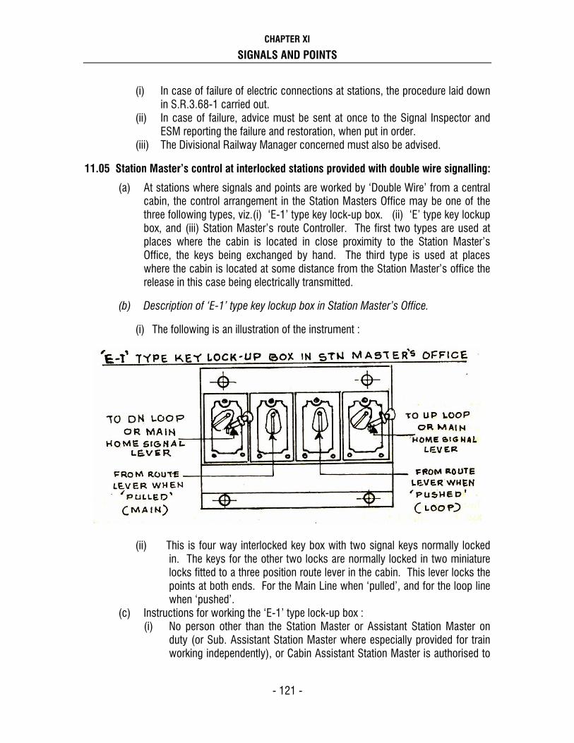
CHAPTER XI
SIGNALS AND POINTS
- 121 -
(i) In case of failure of electric connections at stations, the procedure laid down in S.R.3.68-1 carried out.
(ii) In case of failure, advice must be sent at once to the Signal Inspector and ESM reporting the failure and restoration, when put in order.
(iii) The Divisional Railway Manager concerned must also be advised.
11.05 Station Master’s control at interlocked stations provided with double wire signalling:
(a) At stations where signals and points are worked by ‘Double Wire’ from a central cabin, the control arrangement in the Station Masters Office may be one of the three following types, viz.(i) ‘E-1’ type key lock-up box. (ii) ‘E’ type key lockup box, and (iii) Station Master’s route Controller. The first two types are used at places where the cabin is located in close proximity to the Station Master’s Office, the keys being exchanged by hand. The third type is used at places where the cabin is located at some distance from the Station Master’s office the release in this case being electrically transmitted.
(b) Description of ‘E-1’ type key lockup box in Station Master’s Office.
(i) The following is an illustration of the instrument :
(ii) This is four way interlocked key box with two signal keys normally locked
in. The keys for the other two locks are normally locked in two miniature locks fitted to a three position route lever in the cabin. This lever locks the points at both ends. For the Main Line when ‘pulled’, and for the loop line when ‘pushed’.
(c) Instructions for working the ‘E-1’ type lock-up box : (i) No person other than the Station Master or Assistant Station Master on
duty (or Sub. Assistant Station Master where especially provided for train working independently), or Cabin Assistant Station Master is authorised to

CHAPTER XI
SIGNALS AND POINTS
- 122 -
operate ‘E-1’ type key lock-up box. When he leaves Office, he must lock the instrument and keep the key in his personal custody.
(ii) When an up or a down train is to be received at the station the Station Master will select the line and advise the Cabinman to set the requisite route.
(iii) After setting the requisite route, the Cabinman will pull the three position route lever if the route has been set for the main line, or push it, if the route has been set for the loop line. This will release one of the two keys, which prove the correct setting of the route.
(iv) The key so released will be sent to the Station Master’s office, and inserted in the ‘E-1’ type key lock-up box in the appropriate lock and the requisite home signal key withdrawn.
(v) The key thus taken out of the key lock-up box will then be sent to the cabin to unlock the lever working the requisite Home signal and the signal taken ‘off’ for the admission of the train.
(d) Description of ‘E’ type key lock-up box in Station Master’s Office:
(i) The following is an illustration of the instrument :
(ii) This is a five-way interlocked box for a two line station as shown in the illustration, or seven-way interlocked key box for a three line station. In each case the up and down Home signal lever keys are normally locked in the key box and the route key is normally locked in the miniature lock fitted to a miniature route lever in the cabin. This lever, when operated, locks all points in either normal or reverse position and releases the route key. A Station Master’s lock-up slide is provided on the key lock-up box and this slide in turn is locked by a key kept in the possession of the Station Master.
(e) Instructions for working the ‘E’ type key lock-up box :
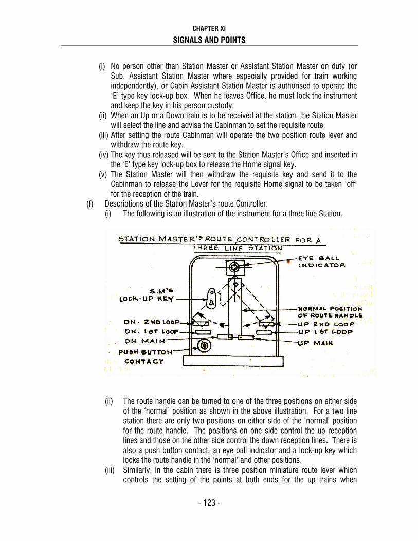
CHAPTER XI
SIGNALS AND POINTS
- 123 -
(i) No person other than Station Master or Assistant Station Master on duty (or Sub. Assistant Station Master where especially provided for train working independently), or Cabin Assistant Station Master is authorised to operate the ‘E’ type key lock-up box. When he leaves Office, he must lock the instrument and keep the key in his person custody.
(ii) When an Up or a Down train is to be received at the station, the Station Master will select the line and advise the Cabinman to set the requisite route.
(iii) After setting the route Cabinman will operate the two position route lever and withdraw the route key.
(iv) The key thus released will be sent to the Station Master’s Office and inserted in the ‘E’ type key lock-up box to release the Home signal key.
(v) The Station Master will then withdraw the requisite key and send it to the Cabinman to release the Lever for the requisite Home signal to be taken ‘off’ for the reception of the train.
(f) Descriptions of the Station Master’s route Controller. (i) The following is an illustration of the instrument for a three line Station.
(ii) The route handle can be turned to one of the three positions on either side
of the ‘normal’ position as shown in the above illustration. For a two line station there are only two positions on either side of the ‘normal’ position for the route handle. The positions on one side control the up reception lines and those on the other side control the down reception lines. There is also a push button contact, an eye ball indicator and a lock-up key which locks the route handle in the ‘normal’ and other positions.
(iii) Similarly, in the cabin there is three position miniature route lever which controls the setting of the points at both ends for the up trains when

CHAPTER XI
SIGNALS AND POINTS
- 124 -
‘pulled’ and for the down trains when ‘pushed’. This lever will not move if the correct route is not set.
(iv) Eye ball receiving indicators are also installed in the cabin to indicate to the Cabinman the line on which the train is to be received, each indicator being connected electrically to one of the positions on the Station Master’s Route Controller.
(v) Where the last Stop signals are controlled through the block instrument, separate eye-ball indicator for such signals is provided which is illuminated when ‘Line Clear’ is received and the handle of the block instrument is turned to ‘Train Going To’ position.
(g) Instructions for working the Station Master’s Route Controller and the three
position route lever in the cabin.
(i) No person other than the Station Master or Assistant Station Master on duty (or Sub Assistant Station Master where especially provided for train working independently), or Cabin Assistant Station Master is authorised to operate the Station Master’s Route Controller, when he leaves office he must lock the instrument and keep the key in his personal custody.
(ii) When an Up or Down train is to be received the Station Master will select the line for the reception of the train and telephone to the Cabinman in the cabin advising him accordingly.
(iii) The Station Master will then turn the route handle to requisite position which will illuminate the corresponding eye ball indicator in the cabin.
(iv) The Cabinman will then set the route indicated, and ‘pull’ the three position route lever in the case of up trains and ‘push’ it, in the case of down trains, thus locking the route set up. He will then take ‘off’ the relevant signals for the reception of the train.
Note : When once the route has been set and locked by the route lever, the route cannot be
altered. If it is to be altered, the Station Master will put the route handle back to normal and keep the push button pressed, which will give ‘normal’ indication in the cabin. After getting the normal indication, the Cabinman will restore the three position route lever to the normal position. This will cause the eye ball indicator on the Station Master’s Route Controller to be illuminated which will indicate that the three position miniature lever in the cabin, is in the normal position. The route can then be reset as required.
���� ����

CHAPTER XII
PRIVATE NUMBER AND TRAIN SIGNAL REGISTER
- 113 -
CHAPTER XII
PRIVATE NUMBER AND TRAIN SIGNAL REGISTER
(A) Private Numbers
12.01. Private Numbers, issue of —
(a) Every ‘Line Clear’ message shall be supported by a Private Number by the Station Master giving ‘Line Clear”.
(b) The Private Number shall form part of the ‘Line Clear’ message and shall be signalled as the last word in it. When a Private Number is given or exchanged, it must be given as one number thus 28, and also as two eight. The receiving station will repeat the same number to assure the sending station that the number has been correctly understood.
(c) A Private Number, given while granting ‘Line Clear’ which is subsequently, cancelled shall not be given again. A fresh number shall be given to each ‘Line Clear’.
(d) The entry of a Private Number will be held to certify that the ‘Line Clear’ has been given, by the Station Master on duty.
(e) Record of all the Private Numbers issued and obtained must be made in the Train Signal Register.
(f) When a Private Number has been used, the figures are to be scored out by drawing in ink a diagonal line through them, care being taken that the number thus cancelled is not obscured or obliterated. The train number for which the Private Number is used must be entered by Station Master/ Switchman/ Cabinman in the column provided for the purpose.
(g) After taking over charge, the Station Master / Switchman / Cabinman should draw a horizontal line below the last Private Number issued, and enter the date and duty hours thus.
Date 29-02-08 Duty 00-08
2809 Dn. 8029 Dn.
______________________________ Date 29-02-08 Duty 08-16
8030 Up 2106 Up
_______________________________ Date 29-02-08 Duty 16-24

CHAPTER XII
PRIVATE NUMBER AND TRAIN SIGNAL REGISTER
- 114 -
12.02 Private Number Sheets —
(a) Private Number Sheets will be supplied by the Divisional Safety Officer. Private Number Sheets of the same series are not to be issued to adjoining stations, i.e. if A series is supplied to station ‘Y’, different series should be supplied respectively to station ‘X’ on one side and to station ‘Z’ on the other side. Private Number sheets of the same series are also not to be supplied to the same station in succession.
(b) Only one Private Number sheet will be supplied for use to each station or block cabin at a time, and when not in use, it will be kept under lock and key by the Station Master. No other person will be allowed to have access to it, except an authorised official for the purposes of enquiry or inspection. When in use it must be in the personal custody of the Station Master on duty.
(c) Station Master shall ask for a fresh Private Number sheet from Divisional Safety Officer when the one in use is nearly exhausted. If for any reason a fresh Private Number Sheet is not available, when the one in use has expired, the Station Master will prepare a manuscript Private Number sheet in the same form as the printed sheet, inserting his own numbers (which are not to follow a serial order or the series in the expired sheet), and this manuscript sheet should be cancelled immediately on receipt of the fresh Private Number sheet and sent to the Divisional Office for record with an explanation for its use.
(d) Should it occur from any cause ( such as misprint or the changing from one series to another ) that a Private Number is the same as the last one issued, the issuing station will cancel this number in his sheet, add the remark ‘Same as last Private Number’, sign it and issue the next different number. Should the messages have been completed before the duplication of numbers is discovered, it shall be cancelled and entirely re-written with a fresh and different Private number.
See - S.R. 3.51 – 4 (b) (ii), S.R. 15.06 – 2 (iii), S.R. 16.03 –2 (vi)
(B)TRAIN SIGNAL REGISTER
12.03 Train Signal Register - Train signal registers are used as under –
(1) On single line ( T-137.B) (2) On Double line (T-66.B) (3) On Multiple line ( As per special instructions ) (4) On Automatic section, when all signals fails, all communication fails or TSL
Working introduced.
{ See S. R. 9.12 – 1 (9), S.R. 9.12 – 2(10) & S.R. 9.12 – 3 (5) }.

CHAPTER XII
PRIVATE NUMBER AND TRAIN SIGNAL REGISTER
- 115 -
(a) The exact time at which all signals are sent or received on the block instruments or through other means and also the Private Numbers used shall be entered, immediately after being acknowledged, in the Train Signal Register by the SM/ASM/CASM/Switchman on duty.
(b) The entries shall be in ink and no erasures shall be made in any circumstances. If an incorrect entry is made, a line shall be drawn lightly through it and the correction made above it and initialed so that the original entry may be clearly seen.
(c) The person who keeps the books shall be responsible for all entries made therein and for correctly filling in each column thereof.
(d) The Station Master, who makes any entry for a train, shall continue on duty till all entries affecting that train are completed. The SM/Switchman who grants Line Clear for a train shall remain on duty till the train has arrived and the ‘Train out of Section’ signal has been given and acknowledged. The SM who receives Line Clear for a train shall remain on duty till the ‘Train out of Section’ signal is received and acknowledged.
Except for completing the transaction in respect of such particular train or trains for which permission to enter block section in rear or in advance has been given or obtained as the case may be, the change of duty shall take place according to the prescribed duty roster.
(e) A line shall be drawn right across the Train Signal Register whenever the Station Master changes the duty, and the outgoing Station Master shall sign his name legibly and enter the time above the line or make any of the following endorsements as may be appropriate in the event of his having to sign ‘off’ at any time after his rostered duty hours, terminate :-
‘Signed off at _________ hours in order to admit __________ Train, arrived at __________ hours’.
OR
‘Signed off at _________ Hours in order to receive train out of section report for __________ train despatched to __________ station arrived there at __________ hours’.
Similarly, the incoming Station Master shall sign his name legibly and enter the time below the line.
(f) In case of Material Trains and Lorries / trolleys working on the line, in the block section or under exceptional circumstances when a section is likely to remain occupied for longer periods as in case of accidents, engine failures and OHE failures, the sub-rule (d) need not be observed.

CHAPTER XII
PRIVATE NUMBER AND TRAIN SIGNAL REGISTER
- 116 -
The Station Master/ CASM / Switchman, may after making the necessary entries in the Train Signal Register and station diary, sign ‘OFF’ duty, such entries being initialed by the outgoing and incoming Station Masters/Switchmen.
The entry regarding the block section being occupied shall be made in red ink in the Train Signal Register and Station diary.
(g) Station Master at Station where another person maintains the Train Signal Register must personally examine the Register daily and certify to its correctness by signing it, all irregularities noticed therein being reported to the Divisional Safety Officer. The Train Signal Register must not be taken out of the office or cabin in which the block instruments are placed without the authority of the Divisional Operating Manager.
(h) The Transportation Inspector and the Signal Inspector must regularly visit each station or cabin and test correctness of the entries in the Train Signal Register and/or in the Enquiry and Reply Books and sign them in token of having checked them.
(i) The ‘blocking back’, the ‘blocking forward’ and the ‘obstruction removed’ signals when used should be entered in the Train Signal Register on the next blank serially numbered line, exactly as a train entry is made.
The entry should be ‘B’ cabin blocked back at 21-05’’ or ‘B’ cabin blocked forward at 21-05’’ and ‘B’ cabin obstruction removed at 22-10’’ the entry should be initialed. The ‘remarks’ column should not be used for these entries.
(j) Whenever a vehicle has to be detached on a running line, the Station Master on duty must advise the cabin concerned confirming this by exchange of Private Numbers with CASM’s/ Switchman/Cabinman to place lever collars on the signal levers and/or slot levers controlling the concerned Home Signal/Routing signal.
The line should be cleared as early as possible and when the obstruction is removed the CASMs/Switchmen Cabinmen concerned should be immediately advised by exchange of Private Numbers to enable them to remove the lever collars from the respective lever and / or slot lever controlling the concerned Home Signal/Routing signal.
A suitable entry should be made in the Train Signal Register and in the diary on both the occasions.
Note : For Specimen Sheets of Train Signal Register used on the Single and Double Line see, APPENDIX.
���� ����

CHAPTER XII
PRIVATE NUMBER AND TRAIN SIGNAL REGISTER
- 117 -

CHAPTER XIII
PANEL WORKING
- 113 -
CHAPTER XIII
PANEL WORKING
(A) PANEL INTERLOCKING
13.01 (i) PANEL :
A control panel with illuminated Diagram is for operation of points, signal etc for train movement in the stations/cabins/yard.
(ii) PANEL INTERLOCKING : ( WHERE USED)
This is a system of centralised operation of points and signals provided normally at a way side station. This is used normally -
a) As a replacement of the existing Mechanical installation. b) At new crossing stations opened at trunk routes. c) At stations to be converted from MG to BG. d) At any other stations where necessity is felt from operating point of view. e) On uneconomic branch lines to cut down losses.
Generally panel interlocking is provided with full compliment of colour light signal, electrically operated motor point machines and track circuits or Axle Counters. The combined Control Panel and illuminated diagram depicts a schematic representation of track layout, signals and points controlled by the panel. Adjoining track circuits are shown in different colours, indications regarding setting of points, setting of routes, occupation of track circuit and the signal aspects are provided on the panel.
(ii) PRINCIPAL OF OPERATION :
Panel interlocking is of two types :
a) Japanese type. b) German type.
In both the above systems the entrance and exit principal is adopted which is more widely termed as NX system of working.

CHAPTER XIII
PANEL WORKING
- 114 -
(iv) REQUIREMENT OF NX SYSTEM OF WORKING :
1. All points in the route including overlap and isolation are set individually to the required position.
2. The route is set to the required line and signal cleared afterwards. 3. As the train passes and clears the route, the route gets released by the
passage of train.
(v) SIEMEN'S SYSTEM OF OPERATION (NX TYPE) :
The points are first set by operating the individual point button and the point group button, every time the buttons are operated; the points are turned from one position to the other. The position of point is indicated by a white strip of lights. After the individual points in the route, overlap and isolation are operated to the required position, the route is initiated by simultaneously operating the concerned signal button and the relevant route button. This operation of keeping both the buttons pressed simultaneously for about 2 to 3 seconds sets the route and clears the signal to the 'OFF' position. The signal indication is given by a green indication on panel which shows that the signal is 'OFF' irrespective of position of signal outside (whether yellow or double yellow or green). The route set for the train is also indicated on the panel by continuous strips of white lights extending not only from the signal to the next signal in advance, but for the overlap portion also.
As the train occupies and clears the track circuits in a sequential order, the route indicated by white light turns red thereafter to blank. As the train clears a particular sub-route only that route is released. Thus the whole route gets released automatically by the occupation and clearance of the track circuits. The points in the route gets locked electrically when a signal for that particular route is cleared to 'OFF' this is indicated by a "white dot" at the converging point on the panel near individual points in the route.

CHAPTER XIII
PANEL WORKING
- 115 -
13.03. COLOUR CODE OF BUTTONS :
Colour code is adopted so that the buttons can be easily recognised by the Operator. Sr. No
Description Code Colour Remarks
1 Main signal button S.GN. Red Indicates signal number. 2 Shunt signal button. SH.GN. Yellow Indicates signal number 3 Track or route button. UN Grey
4 Button controlling intensity of illumination on panel board.
1,2,3,4 Grey
5 Button controlling intensity of signal illumination.
White
6 Individual point button. WN Blue 7 Individual point button used for
sub-route release WN Blue
with white Dot on top
8 Overlap release button. OYN Grey With counter. 9 Emergency route release Button. EUUYN Grey With counter. 10 Emergency route section release
button. EUYN
Grey With counter,
Sealed button key of SI is required to operate.
11 Common push button for points (Point Group button)
WWN Blue
12 Points emergency push button EWN
Blue With counter. Sealed button
13 Signal cancellation button ERN / EGGN
Red
14 Two ‘bell off’ buttons with indication for silencing the bell / buzzer when the signal bulb fuses or point fails.
G / XYN
W / XYN
White
White
15 Button for operating ‘Calling ON’ signal
COGGN
Red With counter.
16 Signal, Route, and point button checking indication with letters ‘S’, ‘R’ and ‘P’ and prolonged button operation check indication.
Grey Prolonged operation of Signal / route / point button gives this continuous Audio visual indication; until the

CHAPTER XIII
PANEL WORKING
- 116 -
buttons released. 17 Crank handle release group button CHYN Blue 18 Crank handle cancellation group
button CHYRN Blue
19 Common button for releasing the control for gates
XYN Grey
20 Common button for withdrawal of the control for gates
XRN Grey
21 Button for gate control XN Grey
22 Button for ground frame control YN Grey
23 Button for releasing the control for ground frame
YYN Grey
24 Button for withdrawing the control for G.F.
YRN Grey
25 Common button for introducing Automatic working
AGGN Grey
26 Common button for cancellation of automatic working
AGGYN Grey
27 Bell ‘OFF’ push button for silencing the buzzer when power supply (N1 or N2) fails
N1/ XYN/2
Grey
28 Button for Silencing buzzer For points (Buzzer of push Button for points).
WXYN Grey
29 Button for Silencing buzzer for signals
GXYN Grey
Note: (1) In addition to the button mentioned above special buttons for the giving and cancellation of slots, Block buttons, power supply failure buzzer stopping buttons etc are provided as per the local conditions.
(2) Emergency Point group button (EWN) shall be kept sealed by the SI/ESM of the
section. Whenever the seal is broken, the SI/ESM must be advised immediately for resealing the same.
(3) EUYN shall be kept sealed by SI/ESM of the section. Whenever the route is to be
cancelled EUYN key must be inserted by SI/ESM only on getting in writing from SM/CASM/Panel operator for particular route is required to be cancelled, seal of EUYN button is to be broken and route to be cancelled. SM on duty must ensure that the button is resealed by SI/ESM and entries are signed jointly in the EUYN Register.
13.04. The sequences in which the different buttons have to be operated for different
important operations are given below :-

CHAPTER XIII
PANEL WORKING
- 117 -
SN Operation functions Button to be pressed
Sequence of operation of button Remarks
1 To take 'off' a main signal.
S.GN & UN
Press the relevant signal buttons and route button simultaneously after setting points in route individually.
2 To take 'off' a shunt signal
SH.GN & UN
Press the shunt signal button and relevant route button after setting points in the route.
3 To put back the signal to 'on'
GN & ERN/ EGGN
Press signal button of the cleared signal and the common signal cancellation button.
4 To cancel a route set after replacing the 'off' signal to ON.
GN, UN& EUUYN
Press the concerned signal button and the EUUYN simultaneously, keep signal button pressed, release EUUYN and press the relevant route button.
When the signal is provided with approach / dead approach locking this operation should start only after the white flashing light below the signal configuration on panel becomes steady.
5. To release sub- route under emergency.
WN & EUYN
Press nominated point button for sub-route and common EUYN
This is done with the help of S&T staff since the key will be in the custody of SI/ESM
6 To change the point setting individually with point zone Track Clear
WN & WWN
Press the concerned point button and point common group button simultaneously
7 To change the setting of points individually when point track fails
WN & EWN
Break the seal of EWN and press it simultaneously with relevant point button
8 To release locked overlap in case of failure
OYN & UN
Common OYN and reception line UN are to be pressed together
9 To release crank handle key
CHYN & WN
Crank handle release button and concerned point button
A steady white indication will turn flashing white on panel and at site red indication will appear. On seeing this the ASM can extract the key to enable manual operation of point, and when key extracted the flashing white indication will disappear and

CHAPTER XIII
PANEL WORKING
- 118 -
red illumination will lit on panel.
10 Restoration of crank handles locking key back.
CHYRN & WN
Crank handle operation cancel button and point button to be pressed simultaneously.
After manual operation of point the crank handle key is to be reinserted in the crank handle box. On panel the red indication will disappear and white flashing indication lit. On seeing this the operator withdraw the control and flashing indication will turn into white steady.
11 To release L/Xing gate slot
XN & XYN
L/Xing gate button and common button for releasing the gate slot simultaneously.
A white steady indication will turn flashing the Gateman will get slot indication. On seeing this he will open the gate and on panel, the flashing white will disappear and steady red appears.
12 To withdraw L/Xing gate slot
XN & XRN
L/Xing gate button and common button for withdrawing the gate slot simultaneously.
When Gateman releases the slot, on the panel the red light will disappear and white flashing lit. On seeing the flashing indication the operator will withdraw slot and flashing indication turn steady.
13 To release the control for ground frame
YN & YYN
Slot button for GF & common button for releasing the slot for GF.
The steady white will flash and when at site the lever is operated the white flashing will turn steady red.
14 To withdraw the control for ground frame
YN & YRN
Slot button for GF and common button for withdrawal of slots.
After the operation when control is released at site the white flashing will appear. On seeing this operator will withdraw the slot and white steady will appear.
15 To introduce Automatic working on semi-auto signal
SGN and AGGN
Press signal button (semi-auto) and AGGN common button for introducing Automatic Working, release AGGN. Keep signal button pressed and press relevant route button
16 To cancel Automatic SGN & Press signal button and AGGYN

CHAPTER XIII
PANEL WORKING
- 119 -
working on semi-auto signal
AGGYN & UN
common button for cancellation of automatic working simultaneously, release AGGYN keeping signal button pressed then press the relevant route button.
17 To take 'off' a ‘Calling ON’ signal
S.GN, COGGN & UN
Press signal button and common group button for ‘Calling ON’ signal, release group button for ‘Calling On’ keeping signal button pressed and then press route button. (for Calling On signal the train to be brought to a stand at the stop signal)
A flashing indication on the panel at near the signal will appear which will flash up to 120 second then Calling On will be Off
13.05 PANEL INDICATIONS:
The condition of points, signals and tracks are clearly indicated on the panel by a system of lights. The main signals are given only two panel indications “RED” for ON and “GREEN” for OFF (irrespective of whether the signal displays Yellow, Double Yellow or Green) only the “OFF” indication is chosen because the operator has no influence on the different “OFF” aspects as these are determined in advance by the inherent and embedded interlocking in the selection of the route. For a shunt signal on a post by itself, a horizontal strip of light indicates ‘ON’ and oblique light of strip indicates ‘OFF’ aspect.
A small white light is lit under a signal configuration when the signal is dead approach / approach locked and the signal is thrown to danger, then the route for cancellation will be initiated, the light will flash for 2 minutes and becomes steady, then only the operator can cancel the route.
Signal lamp failures are indicated by flashing red or green at the appropriate signal configuration.
One of the two white strip lights (one for normal and the other for reverse) is lit at the point configuration to indicate position of points, immediately the point button and the common group button are pressed and the point indication therefore shows the intended position, while the points are working and till such time the points are correctly set and locked a white strip will flash, the flashing continues till such time the points are correctly set and relevant point button is released. When point track failed or is occupied all lights of the point configuration turn to red straight or reverse point indicating strip, if the point track is occupied by a train. The operation of the above button when carried out, reasons to be recorded in the register meant for them with prescribed format.
During the failure of main signals due to track circuits failure except the track circuit immediately ahead of the signal, the “Calling on” signal can be taken “OFF” provided other conditions for the taking 'off' the signal concerned has been fulfilled and the approach track immediately in rear of the signal is occupied by the train.

CHAPTER XIII
PANEL WORKING
- 120 -
For taking “OFF” “Calling on” signal, the concerned route should be first set in the normal manner then the concerned main signal button, calling on common button (COGGN) and route button should be pressed simultaneously and released, this will cause the approach locking indication to flash for time lapse of two minutes after which the calling on signal will get 'OFF' subject to other required conditions being fulfilled. After a route has been initiated, the red light will be lit only in the direction of movement of the train. Point symbol on the panel is provided with an additional white dot lamp, which appears when the points are locked by a route.
As soon as the route is set by the operation of signal button and relevant route buttons, the route set is indicated by illuminated white strips including the overlap. When train occupies these tracks these indications turn to red and when train clears individual section locking released & these white lights become extinguished. Failure of track is always indicated by red strip light on the track configuration irrespective of whether track has been used by train or not.
Electric counters are provided for certain important common buttons like (1) EWN (2) EUUYN (3)EUYN (4) COGGN and (5) OYN to count the number of operations performed by each of these buttons, the counters are generally kept close to the relevant buttons, EUYN has got separate key lock, where the key in position is provided before sub-route cancellation and this key is in the possession of S.I. / ESM.
The flashing white approach locking indication will disappear when calling on gets 'OFF'. COGGN counter will be increased by one number, record it in COGGN register.
13.06 BUTTONS CHECKING INDICATIONS AND PROLONG OPERATIONS OF BUTTON INDICATORS -
Four button-checking indications are provided on the panel. The indicators bear stenciled letters on them as follows :
(a) Indication with letter ‘S’: This indication disappears as any signal button,, XRN button, CHYN & CHYRN buttons or COGGN buttons are pressed position.
(b) Indication with letter ‘R’: This indication disappears if any route button or gate ‘XN’ button is in pressed position.
(c) Indication with letter ‘P’: This indication disappears if any point button is in pressed position.
(d) Indication GR: If any button on Panel is kept pressed for more than 10 seconds, the concerned button checking indication will disappear on the panel and instead of that another common general button indication GR will appear, accompanied by a buzzer alarm. When this indication appears SM on duty should check up which button checking indication has disappeared and should release the concerned button immediately. This will silence the buzzer and concerned button checking indication will re-appear on the Panel. If the GR indication appears due to any button not returning back to its normal position even after being released, the SI / ESM should be advised by the SM. on duty.

CHAPTER XIII
PANEL WORKING
- 121 -
13.07 CANCELLATION OF A ROUTE ALREADY SET:
The route once set is not to be cancelled as the same gets cancelled automatically by the passage of train. However, in cases of emergency /necessity to cancel a route already set due to any reason, the panel operator on duty should first restore the signal controlling the movement over the route to ‘ON’ by pressing signal button and signal cancellation button (ERN/EGGN), then press the concerned signal button and the emergency route-release button EUUYN simultaneously and release the latter (i.e. EUUYN) keeping the signal button still pressed and then press the concerned route button. This will release the route including overlap, provided no train has occupied the approach track circuit. However if the approach track circuit is occupied the route will not get cancelled immediately but an approach locking indication will appear small circular flashing white light will appear rear signal configuration as soon as the button EUUYN is pressed.
This white light will also appear when the approach to signal is non T.C. and its route is being cancelled. This indication will continue to flash till the time interval stipulated for the release of the approach locking has elapsed; the route should be cancelled as indication above only after the approach locking indication becomes steady. Each time the route is thus cancelled by the operation EUUYN button, it will be recorded on the details of such cancellation will be entered in the proforma in a register maintain for this purpose.
13.08 CANCELLATION OF OVERLAP: After the train arrives and occupies the berthing track, the overlap gets automatically released after the route in rear of the B.T.C. is cancelled after passage of the train. Should the overlap (involving points) not get released automatically after the arrival of the train due to non cancellation of the route section in rear of B.T.C. (which will be indicated by overlap portion remaining illuminated) the panel operator on duty should press the route button in rear of the overlap and the OYN (overlap release button) simultaneously and release them. This will cause a white flashing circular light to appear above the OYN button. The overlap will then automatically release after a lapse of 60 seconds, each time the overlap is thus released, and it will be recorded on the OYN counter provided on the operating panel. The reason and increase in counter no. Should be recorded in the prescribed register.
13.09 RECORDING OF THE READINGS OF COUNTERS. The operation of the following buttons is recorded on the respective counters provided on the panel.
i) Emergency point Button – EWN ii) Emergency route release button – EUUYN iii) Overlap release button – OYN iv) Emergency route section release button – EUYN v) Common button for calling on button – COGGN..

CHAPTER XIII
PANEL WORKING
- 122 -
The panel operator should keep a record of all operations properly; Registers should be maintained for each of the above button operations, the reading of the counter to be recorded mentioning clearly the circumstances under which the operation had to be resorted to. The Cabin Assistant Station Master (panel operator) before handing over the charge to his reliever, he should record the last readings of all the counters in this register, The CASM who takes over the charge must verify by actual observation of the readings on the counters that the last readings have been correctly recorded and singed in token thereof.
13.10 MANUAL OPERATION OF MOTOR POINTS:
13.10.1 Custody of Crank handles:
Crank handles have been provided in a separated glass fronted case for Manual setting of Motor points during failure or for maintenance. These crank handles shall be kept in a case specially provided for this purpose. Electrically locked in separate key locked relay box is kept padlock by CASM (I/C) and sealed by S&T Staff.
Circular white and red light indications have been provided on panel separated for each group as stated above indicating whether the crank handle controlling key is held locked in the key locked relay or it has been released for manual operation of points. For releasing control of crank handle key for every group the CASM (P.O.) will press the ‘CHYN’ and the point button of the first point in the respective point group simultaneously and release. This will cause the white indication of the particular group to flash till the crank handle is taken out from the key locked relay. When the crank handle key is taken out the flashing indication will disappear and red circular indication of the particular group will appear. The insertion of crank handle key in the key locked relay and its operation will cause the red indication of this group to disappear and again flashing white indication will appear. CHYRN (Crank Handle Release Cancellation) and the button of the first point in the particular group must be pressed simultaneously. This will cause the flashing white indication to become steady. Once the control on the crank handle key has been released, the corresponding routes and signals cannot be initiated. After releasing the control if the crank handle key is not extracted, Control can be withdrawn by operating CHYRN and corresponding point button simultaneously. At site of the key locked relay box the control for taking out the key in the key locked box and then only the particulars key can be extracted, this light will disappear as soon as the key is extracted or the control is withdrawn.
13.10.2 Failure of crank handle key:
In case due to any failure, it is not possible to extract crank handle key from key locked relay, the ESM on duty at the cabin shall be informed immediately in writing by CASM on duty. The ESM after ensuring that the intended interlocking is defective in the extraction of key or signal moves over the concerned group of points is not possible; ESM shall arrange to extract the key on the key lock relays for use. However when the use of this

CHAPTER XIII
PANEL WORKING
- 123 -
is made for manual operation of any points, it will be the personal responsibility of CASM on duty to ensure safe passage of trains over the concerned points.
13.10.3. Use of crank handle during Maintenance:
Whenever it becomes necessary for the crank handle to be used for general maintenance and repairs, a member of the S&T Staff not below the rank of ESM ’A’ will issue a disconnection memo with endorsement on top “Crank handle required” for the concerned points and obtain key from the Cabin Asstt. Station Master (Panel Operator) to open the lock. The seal of the crank handle case will then be broken by S&T Staff in presence of CASM (I/C) on duty before the crank handle is removed, an entry will be made in the crank handle register provided for this purpose, and it will be initialed by the S&T staff who is demanding it. After the purpose for which the crank handle was taken out from the case is over, this will be replaced in the case by S&T staff or site ASM. The crank handle case will be then be locked and sealed as laid down in the above clause. The particulars required in the crank handle register will then be posted against the relevant entry and will be singed by both S&T staff or site ASM and CASM (I/C) on duty. During the period from the issue of disconnection memo by S&T staff and the issue of crank handle to them to the time of its return by them issue of the Reconnection memo, if traffic has to passed on the disconnected point, the following procedure should be adopted. Whenever it becomes necessary for the crank handle to be removed for to pass traffic during point failure, the ASM at site will do so after making relevant entries in the register as detailed, CASM in charge on duty will advise ESM and SI who in the cabin about the failure and record the failure in failure register if attended by ASM (out-door) on duty.
13.10.4. Passage of trains when points are defective:
1) When a motor point fails to respond to the panel operation, the CASM (In charge) will immediately advise ESM on duty.
2) The CASM (I/C) will instruct the site ASM about the movement required giving full details about the setting of the route, this advice will be confirm by exchange of private numbers.
3) The site ASM will remove the crank handle and key proceed to examine point to find out there is any obstruction, if any obstruction is found, the same will be removed and advise CASM (I/C) to attempt once again the setting of points.
4) If no obstruction is found or if the points fail to respond to panel operation after removal of the obstruction, the site ASM will set the points in the required position by crank handling, clamp and padlock the same, retaining the key in his possession and then authorise the CASM Central Cabin on receipt of the advice supported by Private Number will permit the over affected point.
13.10.5. Passage of trains when points are disconnected:
When the S&T staff is attending to disconnected/ defective points and traffic has to be passed over them, the ASM (I/C) will advise the site ASM about the movement required giving full details about the setting of the route. This advice will be confirmed by

CHAPTER XIII
PANEL WORKING
- 124 -
Exchange of Private Numbers. The site ASM will then proceed to the points with the object of getting the points set by S&T staff for the required move, after obtaining the agreement of the S&T staff to the contemplated move, after the points have thus been set, the site ASM will clamp and padlock them retaining the key of padlock in his personal custody. The site ASM while proceeding to the pints will also take with him a special Register maintained for this purpose in which an entry of the move will be made and the signature of the S&T staff obtained against that entry, as assurance that the S&T staff have agreed to the move. The site ASM will also sign against that entry. After this has been done, the site ASM will authorise the CASM (I/C) central cabin to undertake the move by communicating Private Number in support of the same.
13.10.6. Axle Counter Reset:
On panel interlocking station where axle counters are provided on berthing portion and points and crossing within station section.
After the despatch of the train still line occupied indication persist or no train have entered the detection point and the portion where axle counter are provided is to be physically verified by out door ASM/CASM as the case may be. He will extend the co-operation from the site by pressing co-operation button. Panel operator after seeing the co-operative indication will reset the system by inserting the resetting key, which is kept under his personal custody.
In the reset box (ASM Office) the feeder counter will jump one higher number for each reset. The same to be recorded in the register meant for axle counter reset.
13.10.7. Rusty Rails -
Due to the formation of rust or oxidation on the table of the rail, the reliability of track circuit is considerably affected. Under such circumstances a 'Track Clear' indication may be displayed for the concerned track; which is actually occupied.
In respect of the track declared as prone to rust formation / oxidation, the legend 'Rusty Rails' is painted alongside of the relevant track in the yard layout painted on the control panel. Stop / Line Block collars must be placed on the relevant knobs / buttons.
Such portion of the track over which there has been no movement for a period of 24 hours should be deemed prone to rust and STOP / Line Blocks collars must be placed on the relevant signal / point knob.
Normally no vehicle shall be stabled on track circuited area. In emergency, if vehicles are stabled and if the duration of stabling is likely to exceed 24 hours, the Signal Inspector should be informed. The Signal Maintainer / SI (Signal Inspector) shall

CHAPTER XIII
PANEL WORKING
- 125 -
disconnect the track feed battery and reconnect the same only after the stable train / vehicle is cleared from the track.
For the first move, after clearing of vehicle is stabled for more than 24 hours or if there was no movement for more than 24 hours on a track circuited line, the Station Master on duty shall not rely on the indication on the panel but must personally verify that the line is clear and free from obstruction for the second move also, he shall personally ensure the condition of the track as explained above and if the indication of the panel is correctly displayed on both directions these occasions he can rely on the indication on the panel for subsequent moves. Otherwise the track circuited portion is to be treated as failed, stop collars should be placed on the relevant buttons on the panel and trains dealt with in accordance with the relevant provision contained in GRs 3.68 to 3.70 and the subsidiary rules there under. Failure messages must be send to the Signal Inspector for early rectification. The permanent way inspector of the Section also must be advised.
The failure / suspension of track circuit and certification by the Signal Inspector regarding safe functioning of the track circuit must be recorded in the Signal Failure Register.
Uninsulated trolleys should not be used on track circuited section. Since a trolley, lorry or motor trolley may fail to shunt the track the Station Master on duty should personally ensure that the track is clear of such vehicles before clearing the Signal for another train or operating the points.
13.11 General Instructions:
(1) Defective signal: When a signal which detects points is defective, all the points detected by such a signal must be treated as non-inter-locked (All signals worked from Panel detecting points in the routes). The SM on duty shall be personally responsible to verify that the points are correctly set, clamped and pad-locked before authorising movements of any train or vehicle over them as per SR 3.68-1 of G&SR Rules.
(2) When a light Diesel/AC engine or any other light self propelled vehicle is to be passed over a cross-over controlled by a track-circuit, the SM on duty must in addition of watching the track circuits on the control panel, ensure through personal visual verification that the Diesel/AC engine light vehicle etc. has cleared the concerned Track-circuit before interfering with the points set for the previous move or before permitting any other move on the aforesaid lines.
(3) The panel is provided with SM’s key to prevent unauthorised operation of points and signals. Normally all the buttons of control panel are ready to be operated at any

CHAPTER XIII
PANEL WORKING
- 126 -
time unless SM on duty locks them up by means of the SM’s key. When the control-panel is locked, it will not be possible to operate a point or to take 'off' a signal but the signal can be put back to 'on' . The SM on duty must keep the key in his personal custody whenever he has to leave the panel-room.
13.12 Safe Working Practices:
1. Panel key shall be in SM’s custody whenever he / she leave his / her office. 2. Line Block collars / caps should be used on occupied line. 3. SM / ASM shall take acknowledgement of S&T staff before handing over relay room
key. 4. All important key shall be kept in the nominated box and the box shall be kept locked. 5. In the event of any signs of tampering with the seals, the SM / ASM shall immediately
advise to S & T staff. 6. If flashing of points is observed on the panel SM / ASM shall immediately send
Pointsman to ensure that no obstruction in the point. 7. If there has been no train movement for 24 hours over a particular line SM / ASM shall
physically ensure that line is clear before authorising any movement. 8. If the flasher light on the Panel becomes steady / blank, SM / ASM shall immediately
inform S & T staff. 9. If S.R.P. light goes off SM/ASM should checkup the buttons thoroughly and seek
assistance of S & T staff if required. 10. Ensure that different counters functioning properly and entries are made in the
concerned registers. 11. Whenever the crank handle is to be used for setting points it shall be done under the
supervision of SM / ASM on duty for correct setting and locking of points. 12. No unauthorised person shall be allowed to operate control panel, setting and locking
of points with crank handle. 13. Unsignalled movement or in case of signal failure all the points (facing and trailing) in
the route must be set, clamped and pad locked.
(B) ROUTE RELAY INTERLOCKING
13.13 The major stations / yards with complicated and extensive lay outs where a large number of trains and shunting movements take place, may be provided with Route Relay Interlocking (RRI). In RRI the points and signals are power operated. The control panel is provided in a Central Cabin.
All buttons provided on control panel are same in colour, code, indication and counters as in panel interlocking with operational difference of route setting and cancellation of overlap.
In RRI, route including overlap is set by single simultaneous operation of just two buttons i.e. signal button and route button (with setting of all individual points in the route and clearance of signal to 'OFF' ). The overlap set for reception of any train did not cancel automatically on arrival of train, until train passes over it or it has to be

CHAPTER XIII
PANEL WORKING
- 127 -
cancelled before any other move involving the overlap is to be made. In RRI, End Block Cabins are provided to control the movement of trains between adjoining block stations. Such movement within RRI jurisdiction and End Block Cabins is controlled by means of control slots.
13.14 Relay Room : At every Block Station where the train operation is involved through
button operation a relay room is provided to ensure the following through relays : -
1. When trains are to be crossed or overtaken at stations, points and signals is to be ensured in proper sequence to make passage of trains safe, and to achieve this interlocking of the operation of points and signals is necessary.
2. Simultaneous movements in stations are also safeguarded by interlocking. 3. Semaphore signals are worked by single wire, double wire or electric motors.
Points are worked by rodding run or double wire or electric power. Interlocking between point levers and signal levers can be effected either mechanically by means of tappets or locking electrically by means of electric lever locks or relays.
4. With Route Relay Interlocking, a complete route can be set by one operation i.e. entrance and exit button and suitably safeguarded against conflicting moves through relays.
13.15 Precautions for effective functioning of Relay Rooms :-
1. All Relay Rooms/ Cabin Basement/Block Instruments should be provided with double locking arrangement. The identification of separate locks should be ensured by marking S&T lock and Operating lock distinctly.
2. One Key of Operating lock shall be with Station Master on duty and spare key with Station Master Incharge in his personal custody.
3. Key of S&T lock should be with S&T maintenance staff of the station. 4. Whenever relay room/cabin basement/block instrument is required to be opened
by S&T staff for maintenance/ attending failures or for any other reason, the key of operating lock from the SM on duty shall be obtained and transaction properly recorded in the Relay Room/Cabin basement/Block Instrument key register maintained at the station/cabin duly signed by concerned S&T staff (with reason quoted) and SM on duty.
5. The operating key shall not be given by the SM on duty unless S&T staff on duty enters the date and time and the purpose of taking the key in the register maintained for this purpose at Station/Cabin and also enter the correct date and time when key is returned to SM on duty.
6. The Relay Room should not be opened frequently and as far as possible the key should be taken only for carrying out schedule maintenance or attending to a failure pertaining to indoor relay equipments or for the inspection of higher officials.
7. Normally relay room of PI/EI/Cabin basement will be opened once in a week and for RRI once in a day for maintenance purpose i.e. cleaning of relay room and other equipments placed in the relay room, taking parameters of voltages etc. or in case of failure if required. However, in monsoon season the key of PI/EI/Cabin

CHAPTER XIII
PANEL WORKING
- 128 -
basement may be taken once during day for adjustment of voltages of track circuit etc..
8. The locking and sealing of the equipments such as block instrument etc. to be ensured once the seal is opened/ broken for whatever the reason it should be sealed again properly with concerned supervisor seal.
9. During the period of signal /points defect/failure and the key for attending the defect has been given to authorized signaling staff, the SM on duty will follow the procedure laid down for working of train when the signal /point is defective as per SR 3.51-1, without waiting for S&T staff to set right the defect. There should be no hesitation/reluctance or inertia on the part of operating staff to proceed to the site for crank handling and clamping the point and passing the train on proper authority.
10. The opening of relay room shall be monitored by data loggers at all the station wherever data loggers have been provided. Where data loggers are not available, the opening of relay room door should be monitored through using Veeder counter.
Relay Room/Cabin basement/Block Instrument Key Register bears the following columns.
Sr.No. Date Time key
handed over to ESM/JE/SE
Reason for taking the key
Signature of ESM/JE/SE
Time key returned to SM on duty
Signature of SM on duty
Remarks
���� ����

CHAPTER XIV
BLOCK PROVING AXLE COUNTER WORKING
- 113 -
Power On
SM’s Key Reset Push
Button Preparatory
Reset Line
Verification Section
Clear
Section Occupied Reset Counter
CHAPTER XIV
BLOCK PROVING AXLE COUNTER WORKING 14.01 (i) BLOCK PROVING BY AXLE COUNTER (BPAC):
In lieu of conventional Track Circuits for the running line between two adjacent block stations, Block Proving Axle counters is provided along with Block Instrument for verification of clearance of Block section.
(ii) WORKING OF BLOCK PROVING AXLE COUNTER
Block proving Axle Counters are provided in between advance starter (Last Stop Signals) of the station and adequate distant beyond the Home Signals of the ahead station in the same direction (block section) on both Up & DN lines on Double line and in advance of Last Stop Signals and UP and DOWN home signals of the station on single line to monitor the status of the Block section. Block proving axle counters are used for clearance of Block pertaining to that Block Section. An Axle Counter Indication-cum-Reset Box is provided at SM’s office or at a place where the Block Instruments are provided, one each for each Block Section to indicate the clearance of the concerned Block Section and to facilitate Reset in case of axle counter failures.
14.02. DESCRIPTION OF THE INDICATIONS/FEATURES ON THE AXLE COUNTER INDICATION-CUM-RESET BOX
(a) FEATURES
(1) SM’s Key for authorizing reset operations. (2) Reset Push Button for Resetting Axle Counter. (3) Counter for recording Reset Operation.
(b) INDICATIONS
0 0 0 1 4 3

CHAPTER XIV
BLOCK PROVING AXLE COUNTER WORKING
- 114 -
S.N. Colour & Size of CRs Description Remarks 1 Green Light (large) Clear Indicate that the Block section is clear 2 Red Light (Large) Occupied/failed Indicate that the Block section is
occupied/the BPAC has failed 3 Red Signal (Small) Line verification Indicate co-operation button is being pressed. 4 Green Light (Small) Preparatory Reset Indicate that the Axle Counter Resetting
operation at both ends is completed. 5 Yellow Light (Small) Power ‘ON’ Indicate the availability of power supply.
14.03. CUSTODY OF KEYS
The SM’s key of Axle Counter indication-cum-reset boxes shall be kept in a separate Glass Fronted case and the key of the glass fronted case shall be under the personal custody of the SM on duty.
14.04. RESET BUTTON
Reset button is provided in the Reset Box so that whenever the axle counter shows ‘Failed’ (Red Light-Large) condition, the SM on duty can reset the same to normal after ensuring that the block section is clear.
14.05. COUNTER FOR RECORDING RESET OPERATION
Each and every operation of the reset button is countered on a digital counter and shall be recorded in a separate register indicating the movement before and after operation of the reset button as per the following Performa.
SR. No.
Date/Time Axle counter failed after the arrival of Train No.
Private Number given to the station in rear/ advance
Private Number received from the station in rear/ advance
Counter reading before resetting
Counter reading after resetting
Train number dealt after resetting
Private number given after getting ‘Clear’ indication
Private number obtained after getting ’clear’ indication
14.06. INDICATIONS
Indications are provided in the Axle Counter Indication-cum-Reset Box to show the status of the concerned Block Section. The ‘Clear’ (Green Light-Large) indication on the concerned Axle Counter Indication Box shall be observed by the SM on duty before obtaining/granting line clear on the relevant Block section. The axle counter indication-cum-reset Box displays ‘Clear’ (Green Light – Large) indication when the Block

CHAPTER XIV
BLOCK PROVING AXLE COUNTER WORKING
- 115 -
Section is clear of trains/vehicles and ‘Occupied’ (Red Light – Large) indication when the Block Section is occupied or Axle Counter pertaining to that section is failed.
14.07. COMPLETE ARRIVAL OF TRAINS
The sections where BPAC are provided the trains will work as per GR 14.10(4) for ensuring complete arrival of train. In case the Axle Counter shows ‘Occupied’ (Red Light-Large) indication with an Audible Warning, even after the complete arrival of the Train, no effort shall be made forcibly to bring the Block Instrument to ‘Line Closed’ condition. The buzzer shall be acknowledged by pressing the button provided for this purpose. Before initiating action to reset the Axle Counter and permitting the next Train into the Block Section, the SM shall comply with the provisions of GR 14.10(1) ‘when the block section has been cleared by the arrival of the train or by the removal of the cause of blocking, the block section shall be closed by the block station in advance by giving the prescribed bell code signal’. & (2) ‘Before such signal is given, the Station Master shall satisfy himself as per the prescribed special instructions- (a) that the train is arrived complete, or the cause of blocking the section has been removed, and (b) that the condition under which line clear can be given, are compiled with.’ And satisfy that the train, for which line clear is given, has arrived complete. Once the complete arrival of the train is verified, action can be initiated to reset the Axle Counter at both ends of the affects section as per the procedure given under Para 8.
Note: In addition to observing the clear indication on the Axle Counter for ensuring the complete arrival of train, the existing procedure of ensuring the complete Arrival of train by personally verifying the Tail Board/Tail Lamp or by authorised mean in terms of SR 14.10-1 shall continue to be followed. This shall be incorporated in the respective SWR.
(Deleted vide Adv. CS 1/1 ) (Ref. This office note dated 26.09.2011) 14.08. RESETTING PROCEDURE OF AXLE COUNTERS
After ensuring that the Block Section is clear, the Axle Counter shall be reset. The resetting operation shall be resorted to only when there is ‘Occupied’ (Red Light – Large) indication even though the Block Section is clear. The following procedure shall be adopted after advising the S&T staff concerned about the failure of the axle counter.
i. The SM on duty at the receiving station in which the train has arrived complete shall
give a Private Number to the SM at the other end (despatch station) confirming the complete arrival of the train.
ii. The SM on duty at the despatch end shall acknowledge the same by communicating a Private Number.
iii. The key of the reset box shall then be inserted in the reset box, turned and pressed along with pressing of reset push button by both SMs independently.

CHAPTER XIV
BLOCK PROVING AXLE COUNTER WORKING
- 116 -
iv. The reset operation pertaining to Block Section is carried out independently at both ends.
v. ‘Preparatory Reset’ (Green Light – Small) indication, will appear on the Axle Counter Indication-cum-reset Box at both ends to indicate that the Axle Counter resetting operation is complete.
vi. The counter, provided for recording resetting operation will register next higher number. Necessary entries shall be made in the ‘Block Proving Axle Counter Resetting Register’ maintained for this purpose. Similar entries are made by the SM at the other end of the Block Section also.
vii. When the ‘preparatory indication’ appears, the receiving end Station Master should advise the Station Master at the other end that the block section is being closed. The other end SM shall give a PN to this effect to receiving end Station Master.
viii. The receiving end Station Master shall then close the block section by normalising the block instrument.
ix. With the preparatory reset indication available at both Stations, the line clear for the next train can be obtained through the block instrument and LSS can be taken off and the train despatched normally.
x. On clearance of the first train after preparatory reset at the receiving station, the Axle Counter will show ‘clear’ indication at both stations and subsequent trains can be normally dealt.
xi. If on arrival of the first train on preparatory reset, the axle counter does not show ‘Clear’ indication but preparatory indication continues and Block handle will remain locked in TOL position, the block working shall be suspended and S&T officials of the section shall be advised to attend to the failures. And trains will work on laid down procedure for block failure by issuing necessary authorities until the failure is attended by S&T staff and put right.
xii. The entries in TSR shall be made in red ink at both stations whenever ‘line clear’ has been obtained with the Axle Counter showing ‘preparatory reset indication’.
xiii. No attempt shall be made to close the block section on arrival of the train on preparatory reset if Axle Counter is still showing preparatory reset indication, instead of ‘clear’ indication.
14.09. FAILURE OF AXLE COUNTERS
If Axle Counter does not show ‘Clear’ (Green Light – Large) indication, after clearance of the train on ‘Preparatory Reset’, it shall be treated as a failure of Axle Counter. The Block Instrument Working of the concerned Block Section shall remain suspended till S&T staff rectified the same. During this period Trains shall be dealt as per GR 14.13 and block manual paras 4.20 and 10.12 for single line & Double line, and closing of Block Section done as per GR 14.10(1), 2) & (3) and block manual paras 4.16 and 4.17

CHAPTER XIV
BLOCK PROVING AXLE COUNTER WORKING
- 117 -
14.10. WORKING OF TROLLEY/MOTOR TROLLEY/LORRY ETC.
Trolley protection Track Circuit is not provided to prevent the operation of Axle Counter by insulated Trolleys. Only 4/6 spoke trolleys to be used as directed by R Board vide letter No. 2007/sig/M/7 dated 18.06.07. Motor Trolleys, when required to proceed to adjacent station, shall be issued with necessary Authority to proceed, suspending Block Working. After the motor trolley has cleared the section, the SM on duty shall resume block working for subsequent trains. However, in case the Axle Counter does not show clear indication after arrival of the Motor Trolley at the adjacent station, resetting of the axle counter shall be done as per Para 8 and Train operations restored.
14.11. SHUNTING
Shunting shall be done as per the instructions contained in the Block Working Manual. However, after a Block Forward or a Block Back Operation is completed, before bringing the Block Instrument to ‘Line Closed’ position, it shall be ensured that the Axle Counter shows ‘Clear’ (Green Light – Large) indication.
���� ����

CHAPTER XV
AUTOMATIC BLOCK WORKING
- 113 -
CHAPTER XV
AUTOMATIC BLOCK WORKING
15.01. Essentials of the automatic block system on double line -
(1) where trains on a double line are worked on the Automatic block system - (a) the line shall be provided with continuous track Circuiting or axle counters, (b) the line between two adjacent block stations may, when required, be divided
into a series of automatic block signaling sections each of which is the portion of the running line between two consecutive stop signals, and the entry into each of which is governed by a stop signal, and
(c) the track circuits or axle counters shall so control the Stop signal governing the entry into an automatic block Signalling section that - (i) the signal shall not assume an ‘Off’ aspect unless the line is clear not
only upto the next stop signal in advance but also for an adequate distance beyond it, and
(ii) the signal is automatically placed to ‘On’ as soon as it is passed by the train.
(2) the adequate distance referred to in sub clause i) of clause (c) above shall not be
less than 120 metres unless otherwise directed by approved special instructions,
Illustrative diagrams
Automatic change of sequence of aspects being behind the train in three aspects and four aspects signalling is illustrated in the following diagrams which are not drawn to scale.
Automatic change of sequence of aspects behind the train in three aspect signalling
territory
Automatic change of sequence of aspects behind the train in four- aspect signalling
territory

CHAPTER XV
AUTOMATIC BLOCK WORKING
- 114 -
15.02 Failure of signals in the Automatic section - An automatic signal should be considered to have failed when: (i) The signal exhibits no aspect at all, or (ii) The signal displays more than one aspect, or a misleading aspect,
(iii) The signal displays ‘On’ aspect with the block section, protected by it being clear. (iv) The signal continues to bob/flicker and does not assume a steady aspect. (a) The Station Master, on noticing or on receipt of information of failure of
signals shall record the defect in the Signal Failure Register and advise Signal Inspector or Electric Signal Maintainer immediately to rectify the defect. All cases of signal failures should also be reported to Section Controller who shall record the defect in the Signal Failure Register kept for the purpose.
(b) The Station Master of the reporting Station must at once advise by telephone the Signal Maintainer concerned, the Section Controller and the Station Master on duty at the reporting Station immediately in rear, giving the correct number of the signal that has failed.
(c) Whenever a manual Stop signal fails, the instructions contained in GR 3.68, 3.69 & 3.70 and SR’s there under must be observed.
(d) After the failure has been rectified, the Signal Maintainer must immediately advise the Station Master on duty at the reporting station in rear who will inform the Section Controller, giving the time at which the failure was rectified.
15.03 Procedure during failure of Automatic signalling -
When a failure of Automatic signaling is likely to last for some time or cause serious delay , trains shall be worked from station to station over the section or sections concerned under the special instructions contained in SR 9.12-1
���� ����

- 115 -
APPENDIX
Specimen of the Forms used in connection with Train Working

- 116 -
Specimen of Forms used in connection with Train Working
SN CONTENTS Form No. PAGE
1. Train Signal Register, Double line T.66 B I
2. Train Signal Register, Single line T.137 B II
3. Signal &Telecommunication Disconnection/Reconnection Notice T/351 III
4. Advance Authority to Pass Defective Signals T/369(1) IV
5. Authority to Pass Signals in ‘ON’ or Defective Position T/369-3b V
6. Caution Order T/409 VII
7. ‘Nil’ Caution Order T/A409 VIII
8. Reminder Caution Order T/B409 IX
9. Train Examination Advice/Report T/431 X
10. Authority to Receive a Train on an Obstructed Line T/509 XI
11. Authority to Start from a Non Signalled Line T/511 XII
12. Authority to Start from a Line with Common Starter Signal T/512 XIII
13. Authority to Proceed for Relief Engine/Train into an Occupied Block Section T/A 602
XIV
14. Authority for Opening Communication during Total Interruption of communication on Single Line Section T/B 602
XVI
15. Authority for Working of Trains during Total Interruption of Communication on Double line Section. T/C 602
XVIII
16. Authority for Temporary Single Line Working on Double Line Section T/D 602
XX
17. Line Clear Enquiry Message asking Line Clear for Despatch of Trains during Total Failure of Communication on Single Line Section T/E 602
XXI
18. Conditional Line Clear Message T/F 602 XXII
19. Conditional Line Clear Ticket (Up) T/G 602 XXIII

- 117 -
20. Condition Line Clear Ticket (Down) T/H 602 XXIV
21. Message on Restoration T/I 602 XXV
22. Written Permission by Guard to Driver to Proceed to next Station from Mid Section T/609
XXVI
23. Shunting Order T/806 XXVII
24. Authority to Pass Automatic/ Semi Automatic/Manually Operated /Gate Signals T/A 912
XXVIII
25. Authority to Proceed without Line Clear on Automatic Block Signalling Territory T/B 912
XXIX
26. Authority to Proceed for Relief Engine /Train into an Automatic Block Signalling Section T/C 912
XXXI
27. Authority to Proceed on Automatic Block System during prolong failure of Signals T/D 912
XXXIII
28. Train Intact Arrival Register T/1410 XXXIV
29. Line Clear Enquiry and Reply Message Book at Train Despatching station T/A 1425
XXXV
30. Line Clear Enquiry and Reply Message Book at Train Receiving station T/B 1425
XXXVI
31. Paper Line Clear Ticket Up T/C 1425 XXXVII
32. Paper Line Clear Ticket Dn T/D 1425 XXXVIII
33. Trolley/Lorry/OHE Ladder Trolley Notice T/1518 XXXIX
34. Motor Trolley Permit T/1525 XL
���� ����

- 118 -
REGISTER OF CORRECTION SLIPS
Correction slip Date of receipt of correction slip
Correction made
No. Date Item In rule/para Chapter at page