Butterfly valves EN - KIESELMANN · KIESELMANN GmbH Table of contents Butterfly_valves_EN iii Table...
32
Operating instruction Translation of the original Butterfly valve PDF • ak • 18/05/2018 GB ENGLISH
Transcript of Butterfly valves EN - KIESELMANN · KIESELMANN GmbH Table of contents Butterfly_valves_EN iii Table...

Operating instructionTranslation of the original
Butterfly valve
PD
F
• a
k •
18
/05
/20
18 GBENGLISH

KIESELMANN GmbHPaul -K iese lmann-St r . 4-10
75438 Kni t t l ingen
( +49(0) 7043 371-0 • 7 +49(0) 7043 371-125www.k iese lmann.de • in fo@kiese lmann.de
Copyright: © KIESELMANN FLUID PROCESS GROUP

KIESELMANN GmbH Table of contents
Butterfly_valves_EN iii
Table of contents1 General informations .......................................................................................................................................................................... 5
1.1 Informations for your safety...................................................................................................................................................... 5
1.2 Marking of security instructions ............................................................................................................................................... 5
1.3 General designated use .............................................................................................................................................................. 5
1.4 Personnel ...................................................................................................................................................................................... 5
1.5 Modifications, spare parts, accessories .................................................................................................................................... 6
1.6 General instructions .................................................................................................................................................................... 6
2 Safety instructions ............................................................................................................................................................................... 7
2.1 Intended use................................................................................................................................................................................. 7
2.2 General notes ............................................................................................................................................................................... 7
2.3 General safety instructions......................................................................................................................................................... 7
3 Delivery, transport and storage ......................................................................................................................................................... 8
3.1 Delivery......................................................................................................................................................................................... 8
3.2 Transport ...................................................................................................................................................................................... 8
3.3 Storage........................................................................................................................................................................................... 8
4 Specification.......................................................................................................................................................................................... 9
4.1 Modular system........................................................................................................................................................................... 9
4.2 Valve types ................................................................................................................................................................................. 10
5 Function and operation ..................................................................................................................................................................... 11
5.1 Description of function............................................................................................................................................................. 11
5.2 Control system and position indication................................................................................................................................. 11
5.3 Pneumatic valve activation...................................................................................................................................................... 13
5.4 Installation instructions ............................................................................................................................................................ 14
5.5 Commissioning, service and maintenance ............................................................................................................................ 14
5.6 General welding guidelines..................................................................................................................................................... 14
5.7 ATEX - Guidelines..................................................................................................................................................................... 14
6 Technical data ..................................................................................................................................................................................... 15
6.1 Butterfly valve / Intermediate flanged - butterfly valve...................................................................................................... 15
6.2 Leakage - butterfly valves ........................................................................................................................................................ 16
7 Disassembly and assembly .............................................................................................................................................................. 17
7.1 Disassembly ............................................................................................................................................................................... 17
7.2 Assembly .................................................................................................................................................................................... 19
8 Drawings and dimensions................................................................................................................................................................ 20
8.1 Butterfly valve............................................................................................................................................................................ 20
8.2 Intermediate flange-butterfly valves ...................................................................................................................................... 22
8.3 Leakage butterfly valve ............................................................................................................................................................ 25
9 Wearing parts ...................................................................................................................................................................................... 28
9.1 Butterfly valve............................................................................................................................................................................ 28
9.2 Leakage - butterfly valves ........................................................................................................................................................ 28
9.3 Intermediate - butterfly valve.................................................................................................................................................. 28
9.4 Malfunctions .............................................................................................................................................................................. 29
10 Classification....................................................................................................................................................................................... 30

KIESELMANN GmbHTable of contents
iv Butterfly_valves_EN
10.1 Structure of Order Number ..................................................................................................................................................... 30
11 Appendix.............................................................................................................................................................................................. 32
11.1 Declaration of incorporation.................................................................................................................................................... 32

KIESELMANN GmbH | Operating instruction General informations | 1
Butterfly_valves_EN 5 / 32
1 General informations
1.1 Informations for your safetyWe are pleased that you have decided for a high-class KIESELMANN product. With correct application and ad-equate maintenance, our products provide long time and reliable operation.
Before installation and initiation, please carefully read this instruction manual and the security advices con-tained in it. This guarantees reliable and safe operation of this product and your plant respectively. Please notethat an incorrect application of the process components may lead to great material damages and personal in-jury.
In case of damages caused by non observance of this instruction manual, incorrect initiation, handling or ex-ternal interference, guarantee and warranty will lapse!
Our products are produced, mounted and tested with high diligence. However, if there is still a reason for com-plaint, we will naturally try to give you entire satisfaction within the scope of our warranty. We will be at yourdisposal also after expiration of the warranty. In addition, you will also find all necessary instructions and sparepart data for maintenance in this instruction manual.
1.2 Marking of security instructionsHints are available in the chapter "safety instructions" or directly before the respective operation instruction.The hints are highlighted with a danger symbol and a signal word. Texts beside these symbols have to be readand adhered to by all means. Please continue with the text and with the handling at the valve only afterwards.
Symbol Signal word Meaning
DANGER Imminent danger which will result severe personal injury or death.
WARNING Imminent danger which may result severe personal injury or death.
CAUTION Dangerous situation which may cause slight personal injury or materialdamages.
NOTICE An harmful situation which may result in damages of the product itselfor of adjacent vicinity.
INFORMATION Marks application hints and other information which is particularly use-ful.
1.3 General designated useThe fitting is designed exclusively for the purposes described below. Using the fitting for purposes other thanthose mentioned is considered contrary to its designated use. KIESELMANN cannot be held liable for any dam-age resulting from such use. The risk of such misuse lies entirely with the user. The prerequisite for the reliableand safe operation of the fitting is proper transportation and storage as well as competent installation and as-sembly. Operating the fitting within the limits of its designated use also involves observing the operating, in-spection and maintenance instructions.
1.4 PersonnelPersonnel entrusted with the operation and maintenance of the tank safety system must have the suitable quali-fication to carry out their tasks. They must be informed about possible dangers and must understand and ob-serve the safety instructions given in the relevant manual. Only allow qualified personnel to make electricalconnections.

Operating instruction | KIESELMANN GmbH1 | General informations
6 / 32 Butterfly_valves_EN
1.5 Modifications, spare parts, accessoriesUnauthorized modifications, additions or conversions which affect the safety of the fitting are not permitted.Safety devices must not be bypassed, removed or made inactive. Only use original spare parts and accessoriesrecommended by the manufacturer.
1.6 General instructionsThe user is obliged to operate the fitting only when it is in good working order. In addition to the instructionsgiven in the operating manual, please observe the relevant accident prevention regulations, generally acceptedsafety regulations, regulations effective in the country of installation, working and safety instructions effectivein the user's plant.
KIESELMANN GmbH | Operating instruction Safety instructions | 2
Butterfly_valves_EN 7 / 32
2 Safety instruct ions
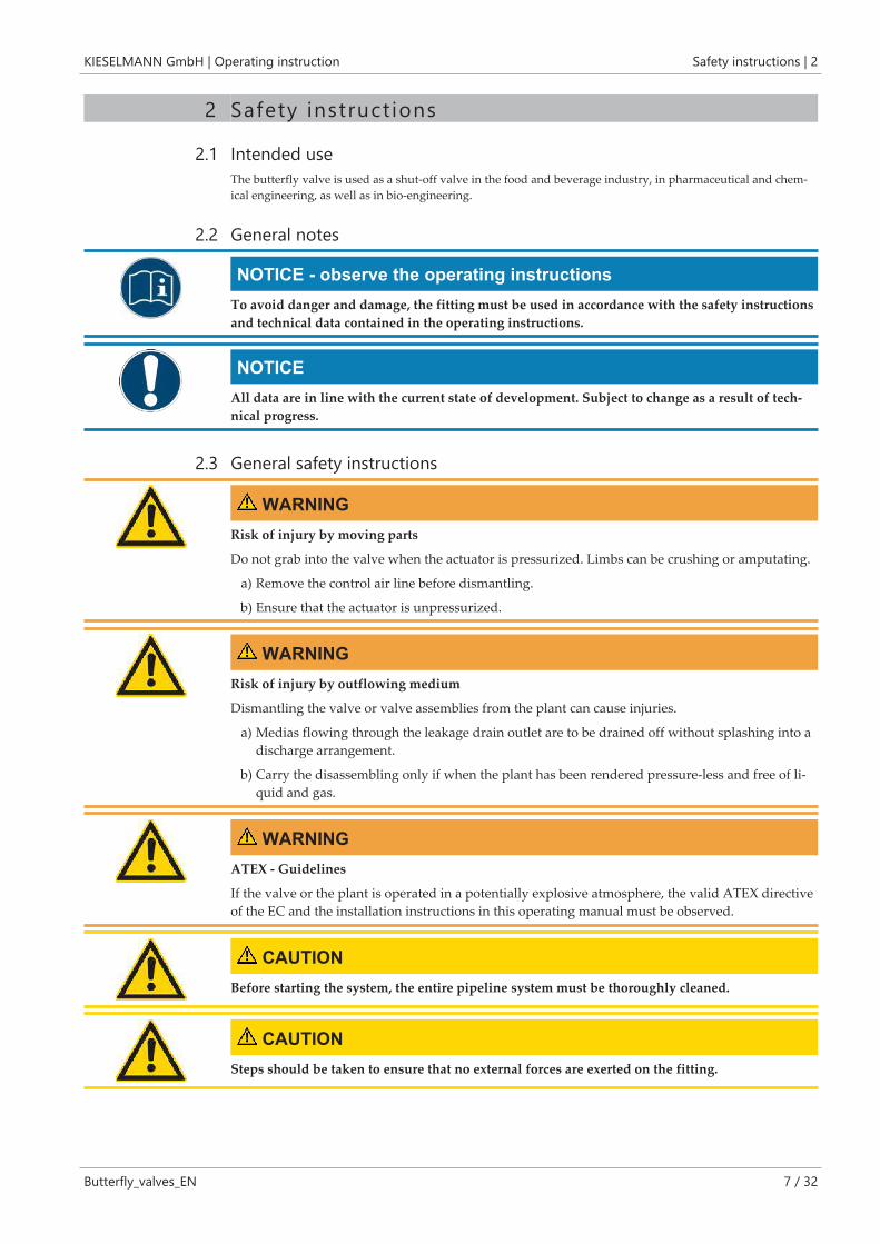
2.1 Intended useThe butterfly valve is used as a shut-off valve in the food and beverage industry, in pharmaceutical and chem-ical engineering, as well as in bio-engineering.
2.2 General notes
NOTICE - observe the operating instructionsTo avoid danger and damage, the fitting must be used in accordance with the safety instructionsand technical data contained in the operating instructions.
NOTICEAll data are in line with the current state of development. Subject to change as a result of tech-nical progress.
2.3 General safety instructions
WARNINGRisk of injury by moving parts
Do not grab into the valve when the actuator is pressurized. Limbs can be crushing or amputating.
a) Remove the control air line before dismantling.
b) Ensure that the actuator is unpressurized.
WARNINGRisk of injury by outflowing medium
Dismantling the valve or valve assemblies from the plant can cause injuries.
a) Medias flowing through the leakage drain outlet are to be drained off without splashing into adischarge arrangement.
b) Carry the disassembling only if when the plant has been rendered pressure-less and free of li-quid and gas.
WARNINGATEX - Guidelines
If the valve or the plant is operated in a potentially explosive atmosphere, the valid ATEX directiveof the EC and the installation instructions in this operating manual must be observed.
CAUTIONBefore starting the system, the entire pipeline system must be thoroughly cleaned.
CAUTIONSteps should be taken to ensure that no external forces are exerted on the fitting.

Operating instruction | KIESELMANN GmbH3 | Delivery, transport and storage
8 / 32 Butterfly_valves_EN
3 Del ivery , t ransport and storage
3.1 DeliveryImmediately after receipt check the delivery for completeness and transport damages.
Remove the packaging from the product.
Retain packaging material, or expose of according to local regulations.
3.2 Transport
CAUTIONRisk of injury and damage to the product
During the transport the generally acknowledged rules of technology, the national accident preven-tion regulationsand company internal work and safety regulations must be observed.
3.3 Storage
NOTICEDamage to the product due to improper storage!
Observe storage instructions
avoid a prolonged storage
INFORMATIONRecommendation for longer storage
We recommend regularly checking the product and the prevailing storage conditions during longstorage times.
• To avoid damage to seals and bearings,
– products up to DN 125 / OD 5 inch should be stored horizontally for maximum 6months.
– products larger than DN 125 / 5 inch, should be stored in the upright position withthe actuator on top.
• Don't store any objects on the products.
• Protect the products for wetness, dust and dirt.
• The product should be stored in a dry and well ventilated room at a constant temperature (op-timal indoor temperature: 25 C ±5 ; indoor humidity data 70% ±5%).
• Protect seals, bearings and plastic parts for UV light and ozone.

KIESELMANN GmbH | Operating instruction Specification | 4
Butterfly_valves_EN 9 / 32
4 Specif icat ion
4.1 Modular systemControl - and feedback units
Electronic control head
KI-TOP
Electro-pneumatical
positioner
Position indication
with sensor mounting
transp. hood stainless steel hood
drive systemspneumatical electrical
PDA 90/75
Ø 75
PDA 90/100
Ø 100
PDA 90/125
Ø 125
Type 4040
manually operatedhand lever hand lever
with sensor mounting
hand lever
stainless steel
hand lever
continuously adjustable
connection flangesS G K/M Fl Cl intermediate
flange S
sealsSilicone EPDM FKM HNBR

Operating instruction | KIESELMANN GmbH4 | Specification
10 / 32 Butterfly_valves_EN
4.2 Valve typesS = Welded end
G = Male
K/M = Liner / nut
Fl = Flange
Cl = Clamp
lö = air open
ls = air close
fö = spring open
fs = spring close
Butterfly valve manually
operated
pneumatical
NC DAS - S DIN 4301 4501 4401
Inch 4351 4551 4451
G - S DIN 4302 4502 4402
Inch 4352 4552 4452
G - G DIN 4303 4503 4403
Inch 4353 4553 4453
K/M - G DIN 4304 4504 4404
Inch 4354 4554 4454
K/M - S DIN 4305 4505 4405
Inch 4355 4555 4455
Fl (PN10) - G
Fl - Fl (PN10)
DIN 4307 4507 4407
Cl - Cl DIN 4346 4546 4446
Inch 4347 4547 4447
Intermediate - butterfly valve manually
operated
pneumatical
NC DAS - S DIN 4310 4510 4410
Inch 4358 4558 4458
KIESELMANN GmbH | Operating instruction Function and operation | 5
Butterfly_valves_EN 11 / 32
5 Funct ion and operat ion
5.1 Description of functionOpen or close the valve by turning the pneum. controlled rotary drive by 90°.
Functional description for butterfly valves - manual operationWhen actuating a fitting manually, the respective switching position will be locked in place in the final position.The manually operated lever is positioned at an angle of 90°in transverse direction to the conduit axis in closedposition The lever is positioned in the direction of the conduit axis in open position.
Description of function for butterfly valves - pneum. operationThe valve opens and closes by way of a pneum. multiturn actuator with a rotary movement of 90°.
normal closed (NC)
• pneum. OPERATED
• not pneum. OPERATED
opens the valve
spring force closes the valve
normal open (NO)
• pneum. OPERATED
• not pneum. OPERATED
closes the valve
spring force opens the valve
double acting (DA)
• pneum. OPERATED the valve opens or closes according to control
Functional description for leakage - butterfly valvesWhen closed, the butterfly valve with a tandem seal ensures that different media remain separated withoutleaking. The medium flows depressurized through the leakage drain ring-groove and out the leakage drain out-let. For hygienically demanding products, we recommend cleaning the leakage drain area (Cleaning connectionR1/4“).
5.2 Control system and position indication
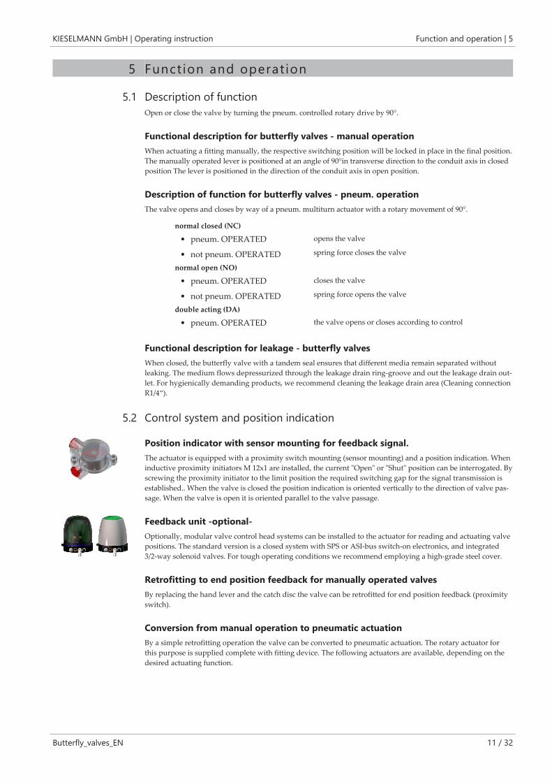
Position indicator with sensor mounting for feedback signal.The actuator is equipped with a proximity switch mounting (sensor mounting) and a position indication. Wheninductive proximity initiators M 12x1 are installed, the current "Open" or "Shut" position can be interrogated. Byscrewing the proximity initiator to the limit position the required switching gap for the signal transmission isestablished.. When the valve is closed the position indication is oriented vertically to the direction of valve pas-sage. When the valve is open it is oriented parallel to the valve passage.
Feedback unit -optional-Optionally, modular valve control head systems can be installed to the actuator for reading and actuating valvepositions. The standard version is a closed system with SPS or ASI-bus switch-on electronics, and integrated3/2-way solenoid valves. For tough operating conditions we recommend employing a high-grade steel cover.
Retrofitting to end position feedback for manually operated valvesBy replacing the hand lever and the catch disc the valve can be retrofitted for end position feedback (proximityswitch).
Conversion from manual operation to pneumatic actuationBy a simple retrofitting operation the valve can be converted to pneumatic actuation. The rotary actuator forthis purpose is supplied complete with fitting device. The following actuators are available, depending on thedesired actuating function.

Operating instruction | KIESELMANN GmbH5 | Function and operation
12 / 32 Butterfly_valves_EN
Butterfly valve / Intermediate flanged - butterfly valveConversion kit A A Pneum. actuator A3 Screws
A1 Square boss A4 Screw
A2 Angle bracket 2 Flap
Nominal diameter
15-20
-
25-40
1“-1½“
50
2“
65-100
2½“-4“
125
-
150
-
200
-
Pneum. actu-ator
conversion kit (A) Function
X X - - - - - PDA 90/75 4500.050.075-022
4500.050.075-022
-----
NC
NO
DA
- X X - - - - PDA 90/100 4500.050.100-022
4500.050.100-022
4400.050.100-022
NC
NO
DA
- - - X - - - PDA 90/100 4500.100.100-022
4500.100.100-022
4400.100.100-022
NC
NO
DA
- - - - X - - PDA 90/125 4500.125.125-022
4500.125.125-022
4400.125.125-022
NC
NO
DA
- - - - - X - PDA 90/125 4500.150.125-022
4500.150.125-022
4400.150.125-022
NC
NO
DA
- - - - - X X PDA 90/125 4500.200.125-022
4500.200.125-022
4400.200.125-022
NC
NO
DA
Leakage - butterfly valvesConversion kit B A Pneum. actuator A3 Screws
A1 Square boss A4 Screw
A2 Angle bracket 2 Flap
Nominal diameter
50-80
2“-3“
65-100
4“
125
-
150
-
Pneum. actuator Conversion kit (B) Function
X - - - PDA 90/100 4500.050.100-022
4500.050.100-022
4400.050.100-022
NC
NO
DA
- X - - PDA 90/100 4500.100.100-022
4500.100.100-022
4400.100.100-022
NC
NO
DA
- - X - PDA 90/125 4500.125.125-022
4500.125.125-022
4400.125.125-022
NC
NO
DA
- - - X PDA 90/125 4500.150.125-022
4500.150.125-022
4400.150.125-022
NC
NO
DA

KIESELMANN GmbH | Operating instruction Function and operation | 5
Butterfly_valves_EN 13 / 32
5.3 Pneumatic valve activationKind of actuator: air open - spring close (NC) / air close - spring open (NO)
Valve function pneum. activationwith solenoid valve in control head
pneum. activationwith external solenoid valve
OPEN Control head
P ➟ MV2 ➟ P2/LA2
Valve is opening by control air
Control head
ext. MV ➟ LA2
Valve is opening by control air
CLOSED Control head
LA2/P2 ➟ MV2 ➟ R
valve is closing by spring
Control head
LA2 ➟ ext. MV
valve is closing by spring
Kind of actuator: air open - air close (DA)
Valve function pneum. Activation via controlhead with solenoid valves
pneum. Activation via externalsolenoid valves
OPEN Control head
P ➟ MV2 ➟ P2/LA2
Valve is opening by control air
Control head
ext. MV ➟ LA2
Valve is opening by control air
CLOSED Control head
P ➟ MV1 ➟ P1/LA1
Valve is closing by control air
Control head
ext. MV ➟ LA1
Valve is closing by control air
NC / NO DA
MV = solenoid valve
ES = de-aeration, sound absorber
P = compressed-air inlet
LA = air supply
S = Slide switch for manual opera-tion of the solenoid valve
SA = sensor mounting
R = Cap
E = de-aeration
LA = air supply

Operating instruction | KIESELMANN GmbH5 | Function and operation
14 / 32 Butterfly_valves_EN
5.4 Installation instructions
5.5 Commissioning, service and maintenance
ServiceThe maintenance intervals depend on the operating conditions "temperature, temperature-intervals, medium,cleaning medium, pressure and opening frequency". We recommend replacing the seals 1-year cycle The user,however should establish appropriate maintenance intervals according to the condition of the seals.
Lubricant recommendation
EPDM; HNBR; NBR; FKM; k-flex - Klüber Paraliq GTE703*
Silicone - Klüber Sintheso pro AA2*
Thread - Interflon Food*
CleaningFor best cleaning results, keep the valve open during cleaning to completely rinse the gasket and the valvehead.
5.6 General welding guidelinesSealing elements integrated in weld components must generally be removed prior to welding. To prevent dam-age, welding should be undertaken by certified personnel (EN ISO 9606-1). Use the TIG (Tungsten Inert Gas)welding process.
CAUTIONDamage and injuries due to high temperature supply
To avoid a distortion of the components, all welding parts must be welded to stress-relieved.
Allow all components to cool before assembling.
NOTICEDamage due to impurities
Impurities can cause damage to the seals and seals area.
Clean inside areas prior to assembly.
5.7 ATEX - GuidelinesFor valves or plants/installations that are operated in the ATEX area, sufficient bonding (grounding) must beensured (see valid ATEX Guidelines EG).

KIESELMANN GmbH | Operating instruction Technical data | 6
Butterfly_valves_EN 15 / 32
6 Technical data
6.1 Butterfly valve / Intermediate flanged - butterfly valveValve size: Butterfly valve : DIN: DN 10 - DN 150; Inch: DN 1“ - DN 4“
Intermediated flanged butterfly valve: DIN: DN 15 - DN 200; Inch: DN 1“ - DN 4“
Connections: Welding flange PN10
Male part DIN11851
Liner/nut DIN11851
Clamp coupling DIN32676
Male part (RJT) (special flange)
Temperature range: Ambient temperature:
Product temperature:
Sterilization temperature:
+4° to +45°C
+0° to +95°C (medium dependent)
EPDM +140°C (SIP 30 min)
HNBR +95°C (SIP 30 min)
Silicone +110°C (SIP 30 min)
FKM +90°C (SIP 30 min)
Operating pressures: Working pressure:
DN 10 - DN 65 / DN 1“ - DN 2½“ = 16 bar *
DN 80 - DN 100 / DN 3“ - DN 4“ = 10 bar
DN 125 - DN 200 = 6 bar
*) Valves with flange coupling PN10 may be used only with a working pressure up to 10 bar.
Leak rate: A (DIN EN 12266-1)
Control air:
(only pneum. operation valves)
Control air pressure:
5,5 - 8,0 bar
Quality of control air:
ISO 8573-1 : 2001 quality class 3
Materials:
in product contact
Stainless steel: 1.4301 / AISI304
1.4307 / AISI304L
1.4404 / AISI316L
Surfaces: Ra < 0,8µm e-polished
Material of seals: EPDM (FDA);
HNBR (FDA);
Silicone (FDA);
FKM (FDA)

Operating instruction | KIESELMANN GmbH6 | Technical data
16 / 32 Butterfly_valves_EN
6.2 Leakage - butterfly valvesValve size: DIN: DN 50 - DN 150
Inch: DN 2“ - DN 4“
Connections: Welding flange
K-welding flange PN10 Nr. 2069
Male part DIN11851
Liner/nut DIN11851
Temperature range: Ambient temperature:
Product temperature:
Sterilization temperature:
+4° to +45°C
+0° to +95°C (medium dependent)
EPDM +140°C (SIP 30 min)
HNBR +95°C (SIP 30 min)
Silicone +110°C (SIP 30 min)
Operating pressures: Working pressure:
DN 50 - DN 100/ DN 2“ - DN 4“ = 10 bar
DN 125 - DN 150 = 6 bar
Cleaning pressure (Medium water):
Cleaning of the leakage line with product-subjected valve: - max. 1 bar
Cleaning of the leakage line with the pipe cleaning: - max. 3 bar
Leak rate: A (DIN EN 12266-1)
Control air:
(only pneum. operation valves)
Control air pressure:
5,5 - 8,0 bar
Quality of control air:
ISO 8573-1 : 2001 quality class 3
Materials:
in product contact
Stainless steel: 1.4301 / AISI304
1.4307 / AISI304L
1.4404 / AISI316L
Surfaces: Ra < 0,8µm e-polished
Material of seals: EPDM (FDA);
HNBR (FDA);
Silicone (FDA)

KIESELMANN GmbH | Operating instruction Disassembly and assembly | 7
Butterfly_valves_EN 17 / 32
7 Disassembly and assembly
7.1 Disassembly
Dismount the drive systemHand lever: Unscrew the screw (H1) and remove the hand lever (H).
Pneum. multiturn actu-ator PDA75, PDA100:
• Butterfly valve
Unscrew the screws (A4) and remove the actuator (A) with the square boss (A1).
• Leakage butterfly valve
Unscrew the screws (A1) and remove the actuator (A) with the square boss (A1).
Pneum. multiturn actu-ator PDA125:
• Butterfly valve
Unscrew the screw joints (A4) - (A5) and remove the actuator (A) with the square boss (A1).
• Leakage butterfly valve
Unscrew the upper both screw joints (5 a,b,d) / (7) and remove the screws (7). Remove actuator (A) and squareboss (A1).

Operating instruction | KIESELMANN GmbH7 | Disassembly and assembly
18 / 32 Butterfly_valves_EN
Dismount seal (3)• Butterfly valve DN10 - DN150
Unscrew the screw joints (4) - (5). Remove housing flange (1a) and (1b).
Unscrew screw joints (5a) - (7). Remove the flange (8) and dismantle seals (9).
Unscrew the screw joints (4) - (5b) and remove the housing flange (1).
• Intermediate flange - butterfly valves DN200
Unscrew screw joints (5a) - (7).
Remove the flange (8) and dismantle seals (9).
Unscrew the screw joints (4) - (5b) and remove the housing flange (1).
Remove scraper ring (11) and dismantle the plain bearing (6).
Remove the back-up rings (3a) and (3b) from the seal (3).
• Leakage-butterfly valve DN50 - DN125
Dismount the leakage drain.
Unscrew the screw joints (4) - (5). Radially remove the valve from the flange connection.
Unscrew the screws (A4) and remove the bracket (A3).
Unscrew the screws (7) and remove the washers (6).
Remove the lower housing part (1b).
Develop out of the upper housing part (1a) the seal (3) with the flap (2).
• Leakage-butterfly valve DN150
Unscrew the screws (14). Remove the cap (13) and seal (12).
Unscrew the screw joints (5 a,b,d) / (7) and remove the screws (7).
Remove the bracket (A3), flange (8) and seals (10).
Unscrew the screw joints (5c) / (4) and remove screws (4). Remove flanges (1).
Remove the plain bearing (9),(11) and disc (15).
Dismount seal (3) from flap (2)
Position the flap (2) in open position to seal(3)
Deform seal (3) oval-shaped with manualforce
Remove the flap (2) with the short shaft endfrom seal (3)

KIESELMANN GmbH | Operating instruction Disassembly and assembly | 7
Butterfly_valves_EN 19 / 32
7.2 AssemblyThoroughly clean and slightly lubricate mounting areas and running surfaces.
Assemble in reverse order.
NOTICEDuring assembly, the following points must be observed!
• Grease the two shafts of the flap (2) before insertingit into the seal (3) using a grease that is suitable forfoods.
• Mount the locking disc (H2) up to the metal stop onthe housing flanges. Possibly tap lightly with a softface hammer and a sleeve.
H2
• When mounting the hand lever (H), be sure thelever orientation is matched up with the positionslot at the square shaft.
– In this way the correct indication of thevalve position by the hand lever is en-sured.
• Do not install the actuator when set to pneumatic ac-tuation (spring closing condition). Close flap (2)(spring closing position) before assembling the actu-ator (A). The position indicator is oriented verticallyto valve passage direction - valve position "shut".

Operating instruction | KIESELMANN GmbH8 | Drawings and dimensions
20 / 32 Butterfly_valves_EN
8 Drawings and dimensions
8.1 Butterfly valve
Drawings(Illustration: G-S, without drive system)
1a = Housing flange with weldingend
1b =Housing flange with thread end
2 = Flap
3 = Seal
4 = Screws
5 = Nuts
K1 = Cap
K2 = Cap
K3 = Cap

KIESELMANN GmbH | Operating instruction Drawings and dimensions | 8
Butterfly_valves_EN 21 / 32
Dimensions
S FlClK/MG
DN / OD d1 d2 d3 d4 d5 L1 L2 L3 L4 L5 H1 H2 Rd
10 (ø10) ø13x1,5 ø62 ø76 - - 24 41 - - - 78 232 Rd28x1/8
15 (ø16) ø19x1,5 ø62 ø76 ø34 - 24 34 41 34 - 78 232 Rd34x1/8
20 (ø20) ø23x1,5 ø72 ø76 ø34 - 24 34 42 34 - 83 237 Rd44x1/6
25 (ø26) ø29x1,5 ø80 ø104 ø50,5 ø115 27 34 49 34 66 95 285 Rd52x1/6
32 (ø32) ø35x1,5 ø86 ø104 ø50,5 ø140 27 34 52 34 66 98 288 Rd58x1/6
40 (ø38) ø41x1,5 ø92 ø104 ø50,5 ø150 27 34 53 34 60 101 291 Rd65x1/6
50 (ø50) ø53x1,5 ø108 ø104 ø64 ø165 29 36 57 36 65 109 300 Rd78x1/6
65 (ø66) ø70x2 ø130 ø104 ø91 ø185 30 38 62 38 73 121 311 Rd95x1/6
80 (ø81) ø85x2 ø146 ø104 ø106 ø200 36 44 73 44 70 129 319 Rd110x1/4
100 (ø100) ø104x2 ø166 ø104 ø119 ø220 34 44 78 44 77 139 329 Rd130x1/4
125 (ø125) ø129x2 ø205 ø129 - ø250 43 55 77 - 82 181 388 Rd160x1/4
150 (ø150) ø154x2 ø240 ø129 - ø285 52 65 89 - 91 199 407 Rd190x1/4
1“ (ø22,9) ø25,4x1,25 ø80 ø104 ø50,5 - 27 34 49 34 - 95 285 Rd52x1/6
1½“ (ø35,1) ø38,1x1,50 ø92 ø104 ø50,5 - 27 34 53 34 - 101 291 Rd65x1/6
2“ (ø47,8) ø50,8x1,50 ø108 ø104 ø64 - 29 36 57 29 - 109 300 Rd78x1/6
2½“ (ø60,5) ø63,5x1,50 ø130 ø104 ø77,5 - 30 38 62 38 - 121 311 Rd95x1/6
3“ (ø72,1) ø76,1x2 ø146 ø104 ø91 - 36 44 73 44 - 129 319 Rd104x1/6
4“ (ø97,6) ø101,6x2 ø166 ø104 ø119 - 34 44 78 44 - 139 329 Rd130x1/4

Operating instruction | KIESELMANN GmbH8 | Drawings and dimensions
22 / 32 Butterfly_valves_EN
8.2 Intermediate flange-butterfly valves
DrawingsIntermediate flange-butterfly valve DN15 - DN150 / 1Inch - 4Inch
1= Housing flange
2= Flap
3= Seal
4= Screws
5= Nut
6= Discs
7= Screws
8= Flanges
9= Seals
K1) Cap
K2) cap

KIESELMANN GmbH | Operating instruction Drawings and dimensions | 8
Butterfly_valves_EN 23 / 32
DrawingIntermediate flange-butterfly valve DN200
1 = Housing flanges
2 = Flap
3 = Seal
3a) = Backup ring upper
3b) = Backup ring lower
4 = Screws
5 = Nuts
6 = Plain bearing
7 = Screws
8 = Flange
9 = Seals
10 = Discs
11 = Scraper ring
H = Hand lever
H1 = Screw
H2 = Locking disc

Operating instruction | KIESELMANN GmbH8 | Drawings and dimensions
24 / 32 Butterfly_valves_EN
Dimensions
DN/OD d1 d2 d3 L1 L2 L3 H1 H2 H3
15 (ø16) ø19x1,5 ø62 ø76 100 53 29 78 232 333
20 (ø20) ø23x1,5 ø72 ø76 100 53 29 83 237 338
25 (ø26) ø29x1,5 ø80 ø104 165 51 27 95 285 386
32 (ø32) ø35x1,5 ø86 ø104 165 51 27 98 288 389
40 (ø38) ø41x1,5 ø92 ø104 165 51 27 101 291 392
50 (ø50) ø53x1,5 ø108 ø104 165 53 29 109 300 401
65 (ø66) ø70x2 ø130 ø104 165 54 30 121 311 412
80 (ø81) ø85x2 ø146 ø104 165 60 36 129 319 420
100 (ø100) ø104x2 ø166 ø104 165 58 34 139 329 430
125 (ø125) ø129x2 ø205 ø129 285 66 43 181 388 489
150 (ø150) ø154x2 ø240 ø129 285 75 52 199 407 508
200 (ø200) ø204x2 ø334 ø129 285 57 28 247 455.5 560
1“ (ø22,9) ø25,4x1,25 ø80 ø104 165 51 27 95 285 386
1½“ (ø35,1) ø38,1x1,50 ø82 ø104 165 51 27 101 291 392
2“ (ø47,8) ø50,8x1,50 ø108 ø104 165 53 29 109 300 401
2½“ (ø60,5) ø63,5x1,50 ø130 ø104 165 54 30 121 311 412
3“ (ø72,1) ø76,1x2 ø146 ø104 165 60 36 129 319 420
4“ (ø97,6) ø101,6x2 ø166 ø104 165 58 34 139 329 430

KIESELMANN GmbH | Operating instruction Drawings and dimensions | 8
Butterfly_valves_EN 25 / 32
8.3 Leakage butterfly valve
DrawingsLeakage butterfly valves DN 15 - DN 125 / OD 1inch - OD 4inch
(Illustration basic vlave Type: LSV 4365 DN65)
1a = upper housing part
1b =lower housing part
2 = Flap
3 = Seal
4 = Screws
5 = Nuts
6 = Discs
7 = Screws
8 = Flange with
) a) Welding connection (2069)
) b) Welding connection (2041)
) c) Male connection
) d) Liner / nut - connection
9 = Plain bearing
10 = Straight pins
A = Actuator
A1 = Square boss
A2 = Angle bracket
A3 = Screws
A4 = Screws
H = Hand lever
H1 = Saucer-head screw
H2 = Locking disc
H3 = Screws
L = Leakage drain
LA = air supply

Operating instruction | KIESELMANN GmbH8 | Drawings and dimensions
26 / 32 Butterfly_valves_EN
DrawingLeakage - butterfly valves DN150
1 = Housing flange
2 = Flap
3 = Seal
4 = Screws
5 = Nuts
6 = Discs
7 = Screws
8 = Welding flange
9 = Plain bearing
10 = O-rings
11 = Plain bearing
12 = Seal
13 = Cap
14 = Screw
15 = Seal
16 = Disc
A = Actuator
A1 = Square boss
A2 = Angle bracket
A3 = Screws
H = Hand lever
H1 = Screw
H2 = Locking disc
L = Leakage drain
LA = air supply
Dimension
DN / OD d1 d2 d3 L1 L2 H1 H2 H3 H4
150 (ø150) ø154x2 ø240 ø129 285 68 199 406 510 155

KIESELMANN GmbH | Operating instruction Drawings and dimensions | 8
Butterfly_valves_EN 27 / 32
Dimensions
BasicType: 4366Type: 4766Type: 4866
S - SType: 4366Type: 4766Type: 4866
G - SType: 4366Type: 4766Type: 4866
G - GType: 4366Type: 4766Type: 4866
K/M - GType: 4366Type: 4766Type: 4866
DN / OD d1 d2 d3 L1 L2 L3 L4 L5 L6 L7 H1 H2 H3 H4 Rd1/Rd2
50 (ø50) ø53x1,5 ø110 ø104 165 38 68 86 109 156 149 148 338 440 84 Rd78x1/6
65 (ø66) ø70x2 ø130 ø104 165 38 68 86 111 166 158 158 349 451 94 Rd95x1/6
80 (ø81) ø85x2 ø145 ø104 165 41 71 89 114 179 158 167 358 460 102 Rd110x1/4
100 (ø100) ø104x2 ø165 ø129 180 41 71 89 118 197 187 178 407 509 112 Rd130x1/4
125 (ø125) ø129x2 ø195 ø129 285 53 87 101 145 193 181 214 421 523 127 Rd160x1/4
2“ (ø47,8) ø50,8x1,50 ø110 ø104 165 38 68 86 - - - 148 338 440 84 Rd78x1/6
2½“ (ø60,5) ø63,5x1,50 ø130 ø104 165 38 68 86 - - - 158 349 451 94 Rd95x1/6
3“ (ø72,1) ø76,1x2 ø145 ø104 165 41 71 89 129 169 - 167 358 460 102 Rd104x1/6
4“ (ø97,6) ø101,6x2 ø165 ø104 180 41 87 101 - - - 178 407 509 112 Rd130x1/4

Operating instruction | KIESELMANN GmbH9 | Wearing parts
28 / 32 Butterfly_valves_EN
9 Wearing parts
9.1 Butterfly valveSeal (3)
DN SILICONE EPDM HNBR FKM
15 - 4328 015 000-054 4326 015 000-050 -
20 - 4328 020 000-054 4326 020 000-050 -
25 4326 025 000-052 4328 025 000-054 4326 025 000-050 4327 025 000-051
32 4326 032 000-052 4328 032 000-054 4326 032 000-050 4327 032 000-051
40 4326 040 000-052 4328 040 000-054 4326 040 000-050 4327 040 000-051
50 4326 050 000-052 4328 050 000-054 4326 050 000-050 4327 050 000-051
65 4326 065 000-052 4328 065 000-054 4326 065 000-050 4327 065 000-051
80 4326 080 000-052 4328 080 000-054 4326 080 000-050 4327 080 000-051
100 4326 100 000-052 4328 100 000-054 4326 100 000-050 4327 100 000-051
125 4326 125 000-052 4328 125 000-054 4326 125 000-050 4327 125 000-051
150 4326 150 000-052 4328 150 000-054 4326 150 000-050 4327 150 000-051
1 4326 026 000-052 4328 026 000-054 4326 026 000-050 4327 026 000-051
1½ 4326 038 000-052 4328 038 000-054 4326 038 000-050 4327 038 000-051
2 4326 051 000-052 4328 051 000-054 4326 051 000-050 4327 051 000-051
2½ 4326 064 000-052 4328 064 000-054 4326 064 000-050 4327 064 000-051
3 4326 076 076-052 4328 076 076-054 4326 076 076-050 4327 076 076-051
4 4326 101 000-052 4328 101 000-054 4326 101 000-050 4327 101 000-051
9.2 Leakage - butterfly valvesSeal (3) Plain bearing (9) Gleitlager (11) Seal (L1)
DN SILICONE EPDM HNBR iglidur® EPDM
50 4378 050 000-052 4377 050 000-054 4378 050 000-050 8050 012 010-060 8050 012 010-060 2354 012 006-054
65 4378 065 000-052 4377 065 000-054 4378 065 000-050 8050 012 010-060 8050 012 010-060 ||
80 4378 080 000-052 4377 080 000-054 4378 080 000-050 8050 015 010-060 8050 015 010-060 ||
100 4378 100 000-052 4377 100 000-054 4378 100 000-050 8050 015 010-060 8050 015 010-060 ||
125 - 4377 125 000-054 4378 125 000-050 8050 020 015-156 8050 020 015-156 ||
150 - 4328 150 000-054 4328 150 000-050 8050 018 006-060 8050 020 015-156 ||
2 4378 050 000-052 4377 050 000-054 4378 050 000-050 8050 012 010-060 8050 012 010-060 2354 012 006-054
2½ 4378 065 000-052 4377 065 000-054 4378 065 000-050 8050 012 010-060 8050 012 010-060 ||
3 4378 076 000-052 4377 076 000-054 4378 076 000-050 8050 015 010-060 8050 015 010-060 ||
4 4378 100 000-052 4377 100 000-054 4378 100 000-050 8050 015 010-060 8050 015 010-060 ||
9.3 Intermediate - butterfly valveSeal (3) Seal (9)
DN SILICONE EPDM HNBR FKM k -flex
15 - 4328 015 000-054 4326 015 000-050 - 2353 021 016-114
20 - 4328 020 000-054 4326 020 000-050 - 2353 028 020-114
25 4326 025 000-052 4328 025 000-054 4326 025 000-050 4327 025 000-051 2353 035 026-114
32 4326 032 000-052 4328 032 000-054 4326 032 000-050 4327 032 000-051 2353 041 032-114
40 4326 040 000-052 4328 040 000-054 4326 040 000-050 4327 040 000-051 2353 047 038-114
50 4326 050 000-052 4328 050 000-054 4326 050 000-050 4327 050 000-051 2353 059 050-114
65 4326 065 000-052 4328 065 000-054 4326 065 000-050 4327 065 000-051 2353 076 066-114

KIESELMANN GmbH | Operating instruction Wearing parts | 9
Butterfly_valves_EN 29 / 32
Seal (3) Seal (9)
DN SILICONE EPDM HNBR FKM k -flex
80 4326 080 000-052 4328 080 000-054 4326 080 000-050 4327 080 000-051 2353 090 081-114
100 4326 100 000-052 4328 100 000-054 4326 100 000-050 4327 100 000-051 2353 109 100-114
125 4326 125 000-052 4328 125 000-054 4326 125 000-050 4327 125 000-051 2353 136 125-114
150 4326 150 000-052 4328 150 000-054 4326 150 000-050 4327 150 000-051 2353 161 150-114
200 - 4328 200 000-054 - - 2353 211 200-114
1 4326 026 000-052 4328 026 000-054 4326 026 000-050 4327 026 000-051 2353 032 024-114
1½ 4326 038 000-052 4328 038 000-054 4326 038 000-050 4327 038 000-051 2353 044 036-114
2 4326 051 000-052 4328 051 000-054 4326 051 000-050 4327 051 000-051 2353 057 049-114
2½ 4326 064 000-052 4328 064 000-054 4326 064 000-050 4327 064 000-051 2353 071 061-114
3 4326 076 076-052 4328 076 076-054 4326 076 076-050 4327 076 076-051 2353 083 073-114
4 4326 101 000-052 4328 101 000-054 4326 101 000-050 4327 101 000-051 2353 107 099-114
9.4 MalfunctionsMalfunction Cause Remedy
Valve does not move - Compressed air missing
- Electrical controller missing
- Actuator defective
- Switch on compressed air
- Check and ensure electrical signals
- Check and ensure electrical signals
Signals do not come on - Loose cable on pilot valve or initiator
- Cable broken
- Initiators defective
- Pilot valve defective
- Electrical supply missing or damaged
- Tighten cable
- Replace cable
- Replace initiators
- Replace pilot valve
- Check or remedy
Valve moves too slowly - Compressed air too low
- Exhaust hole actuator plugged up
- Increase compressed air
- Clear opening
Valve moves unevenly - Compressed air supply too weak
- Media pressure too high
- Electric signals uneven
- Increase compressed air
- Check media pressure and adjust if necessary
- Remedy signal flow malfunction
Valve causes excessive mechanicalnoises
- Lubrication missing - Lubricate seal and guide elements

Operating instruction | KIESELMANN GmbH10 | Classification
30 / 32 Butterfly_valves_EN
10 Classi f icat ion
10.1 Structure of Order Number
4 5 0 2 0 5 0 1 3 0 - K X X X
0 1 2 3 4 5 6 7 8 9 10 11 12 13 14
- Control system and position indication- External surface
Separator
- Material of seals
Valve size DN / OD
Connection variant
Product type DIN / Inch
0 - 2 Product type XXxx xxx xxx-xxxx
0 1 2 3 Designation
4 3 x x Butterfly valve/Leakage butterfly valve manual operating
4 5 x x Butterfly valve/Leakage butterfly valve pneumatic operating
air open- spring close (NC)
4 4 x x Butterfly valve/Leakage butterfly valve pneumatic operating
air open - air close (DA)
2 - 3 Connection variant xxXX xxx xxx-xxxx
z.B. Type 4502 = Male flange / Welding flange
oder Type 4510 = Intermediate
(see Valve types [} 10])
4 - 6 Valve size DN/OD xxxx XXX xxx-xxxx
DN 4 5 6 OD 4 5 6
DN 25 0 2 5 OD 1" 0 2 6
DN 40 0 4 0 OD 1 1/2" 0 3 8
DN 50 0 5 0 OD 2 " 0 5 1
DN 65 0 6 5 OD 2 1/2" 0 6 4
DN 80 0 8 0 OD 3 " 0 7 6
DN 100 1 0 0 OD 4 " 1 0 1
DN 125 1 2 5 -
DN 150 1 5 0 -
DN 200 2 0 0 -

KIESELMANN GmbH | Operating instruction Classification | 10
Butterfly_valves_EN 31 / 32
7 - 9 Material of seals xxxx xxx XXX-xxxx
Sealing material - in product contact 7 8 9
EPDM 1 3 0
HNBR 4 2 0
Silicone 0 0 0
FKM 1 4 0
10 Separator xxxx xxx xxx - xxxx
11 - 14 Control system and position indication , External surface xxxx xxx xxx - xxxx
Control system and position indicator 11 12 13 14
Valve with position indication external surface AISI304 blanc 0 2 0
Valve with position indication external surface AISI304 e-polished 0 2 1
Valve with position indication external surface AISI304 mat finish 0 2 2
Valve with position indication external surface AISI316L blanc 0 4 0
Valve with position indication external surface AISI316L e-polished 0 4 1
Valve with position indication external surface AISI316L mat finish 0 4 2
Valve with control head KI-Top SPS K 5 X X
Valve with control head KI-Top ASI-Bus K 6 X X

Operating instruction | KIESELMANN GmbH11 | Appendix
32 / 32 Butterfly_valves_EN
11 Appendix
11.1 Declaration of incorporation