
Butterfly valve (CPVC disc) - WAFER type Válvula de ...
15
CEPEX EXTREME SERIES DATASHEETS DN PN D Handle Gear box Kv EPDM FPM EPDM FPM 40 10 50 66734 66735 66736 66737 600 l/min 50-65 10 63-75 61498 61504 61526 61534 1.568 l/min 80 10 90 61499 61505 61527 61535 4.980 l/min 100 10 110 61500 61506 61528 61536 7.212 l/min 125 10 125-140 61501 61507 61529 61537 12.320 l/min 150 10 160 61502 61508 61530 61538 25.447 l/min 200 10 200-225 61503 61509 61531 61539 35.778 l/min 250 6 250-280 - - 61532 61540 65.222 l/min 300 6 315 - - 61533 61541 94.660 l/min PRODUCT RANGE Sizes from DN40 up to DN300 [DN250 - DN300 - only gear box] Working pressure at 20°C (73°F) water temperature: D50 – D225 : PN 10 (150 psi) D250 – D315 : PN 6 (90 psi) O-rings in: EPDM (perox.) or FPM (FKM) Standards: ISO-DIN, ANSI, JIS Certifications: CE Options: Electric/pneumatic actuation; limit switch box. CODES RANGO DE GAMA Medidas desde DN40 hasta DN300 [DN250 - DN300 - sólo con reductor manual] Presión de servicio a 20°C (73°F) temperatura de agua: D50 – D225 : PN 10 (150 psi) D250 – D315 : PN 6 (90 psi) Juntas en: EPDM (perox.) o FPM (FKM) Standards: ISO-DIN, ANSI, JIS Certificaciones: CE Opciones: Actuador eléctrico/neumático; caja de final de carrera. CÓDIGOS Butterfly valve (CPVC disc) - WAFER type Válvula de mariposa (disco en CPVC) - tipo WAFER * KV 100 (l/min, Δp = 1 bar) 0045 0045 [DN40 - DN200] [DN50 - DN300]
Transcript of Butterfly valve (CPVC disc) - WAFER type Válvula de ...

CEPEX EXTREME SERIES DATASHEETS
DN PN DHandle Gear box
KvEPDM FPM EPDM FPM
40 10 50 66734 66735 66736 66737 600 l/min
50-65 10 63-75 61498 61504 61526 61534 1.568 l/min
80 10 90 61499 61505 61527 61535 4.980 l/min
100 10 110 61500 61506 61528 61536 7.212 l/min
125 10 125-140 61501 61507 61529 61537 12.320 l/min
150 10 160 61502 61508 61530 61538 25.447 l/min
200 10 200-225 61503 61509 61531 61539 35.778 l/min
250 6 250-280 - - 61532 61540 65.222 l/min
300 6 315 - - 61533 61541 94.660 l/min
PRODUCT RANGE
Sizes from DN40 up to DN300 [DN250 - DN300 - only gear box]
Working pressure at 20°C (73°F) water temperature: D50 – D225 : PN 10 (150 psi) D250 – D315 : PN 6 (90 psi)
O-rings in: EPDM (perox.) or FPM (FkM)
Standards: ISO-DIN, ANSI, JIS
Certifi cations: CE
Options: Electric/pneumatic actuation; limit switch box.
CODES
RANGO DE GAMA Medidas desde DN40 hasta DN300 [DN250 - DN300 - sólo con reductor manual]
Presión de servicio a 20°C (73°F) temperatura de agua: D50 – D225 : PN 10 (150 psi) D250 – D315 : PN 6 (90 psi)
Juntas en: EPDM (perox.) o FPM (FKM)
Standards: ISO-DIN, ANSI, JIS
Certifi caciones: CE
Opciones: Actuador eléctrico/neumático; caja de fi nal de carrera.
CÓDIGOS
Butterfly valve (CPVC disc) - WAFER typeVálvula de mariposa (disco en CPVC) - tipo WAFER
* KV100 (l/min, Δp = 1 bar)
0045 0045
[DN40 - DN200] [DN50 - DN300]

CEPEX EXTREME SERIES DATASHEETS
Material propertiesPropiedades del material
PVC-CDESCRIPTIONThe abbreviation PVC-C stands for chlorinated polyvinylchloride. It is made by post-chlorination of PVC whereby chlorine is attached to the PVC chain. Thus PVC-C is a transformed PVC-U material which, because of its chemical form, is characterised by a higher temperature resistance than PVC-U, with concurrent higher tensile strength, good tenacity and exceptional chemical resistance. Its flammability resistance is even more exceptional than PVC-U. These characteristics have made PVC-C an interesting substitute for piping in the chemical industry as well as for diverse other demanding industrial applications.
PVC-CDESCRIPCIÓNPVC-C es la abreviatura de policloruro de vinilo clorado. Se obitene mediante la post-cloración del PVC, por la que el cloro es agregado a la cadena del PVC. Así, el PVC-C es una transformación del PVC-U que, a causa de su formulación química, se caracteriza por soportar una temperatura mayor que el PVC-U, con el consecuente incremento de resistencia a la tracción, buena tenacidad y excelente resistencia química. Su resistencia a la inflamabilidad es superior al PVC-U. Estas características han hecho del PVC-C un buen sustituto para conducciones en la industria química u otras aplicaciones industriales.
• Rango de temperaturas: 10°C a 80°C en trabajo continuo. Presión nominal en función de la temperatura según gráfico.• Resistente a la abrasión. Buena resistencia mecánica.• No tóxico y libre de corrosión. Apto para uso alimentario.• No inflamable y auto-extinguible.• Resistente a gran variedad de sustancias químicas inorgánicas.• Resistente a la mayoría de soluciones ácidas, alcalinas o sales.• Tubería recomendada para instalaciones por encima del suelo.• No es necesario soporte especial para tubo rígido.• Posibilidad de unión con adhesivo, por junta elástica o por rosca.• Fácil instalación.• No resistente a disolventes orgánicos (ver tabla de resistencias químicas).
• Temperature range: 10°C to 80°C for continous working. Nominal pressure in function of the temperature according diagramm.• Abrasion resistant. Good mechanical strength.• Non-toxic and taint free. Suitable for food and drinking use.• Non flammable and self extinguishing.• Resistant to many inorganic chemicals.• Resistant to most solutions of acids, alkalis and salts.• Pipes are suitable for above ground use.• Rigid pipes: no special support needed.• Jointing by cold solvent welding, rubber ring mechanical joints or threaded.• Easy installation.• Not resistant to organic solvents (see chemical resistance chart for details).

CEPEX EXTREME SERIES DATASHEETS
Features and BenefitsCaracterísticas y Benefi cios
FEATURES BENEFITS
Holes for installation compatible with several standards Same valve used worldwide
One piece body made in PP w/fi ber glass reinforcement (30%) Excellent mechanical strenght
Non wetted SS shaft (AISI 630) No corrosion possibility
Ergonomic handle with lever and locking device Maximum resistance and improved torque
Disc design anti-friction Better torque
Full body linear gasket No need of installation gaskets, leaking proff , completely isolation of the shaft and the body
Machined bearings No shaft disalignment, long life of the valve
Throttle plate w/closing position every 15º Flow control application possible
Double shaft o-ring Installation in any position
100% traceability: serial and batch number Minimize the problems or maximize the solutions
Laser marking of the valve characteristics Easy to see the characteristics and long live
Water and air testing in 100% of the valves Minimum errors in the fi nished product
CARACTERÍSTICAS BENEFICIOS
Agujeros para instalación de brida compatibles con distintos standars Misma válvula usada en todo el mundo
Cuerpo de una sola pieza fabricado en PP con refuerzo de fi bra de vidrio (30%) Excelente resistencia mecánica
Eje en acero inoxidable (AISI 630) sin contacto con el fl uido Sin posibilidad de corrosión
Maneta ergonómica con gatillo y mecanismo de cierre de seguridad Máxima resistencia y par de maniobra mejorado
Diseño de compuerta anti-fricción Mejor par de maniobra
Junta de cierre integral Sin necesidad de junta plana para la instalación, a prueba de fugas, aislamiento completo entre eje y cuerpo
Casquillos mecanizados Evita el desalineamiento del eje, incrementa la vida de la válvula
Conjunto divisor con posiciones de cierre cada 15º Posible aplicación de regulación de caudal
Doble junta tórica en el eje Instalación en cualquier posición
Trazabilidad 100%: número de lote y de serie Minimiza los problemas y maximiza las soluciones
Marcado láser de las características de las válvulas Facilidad para consultar las caracterísitcas y larga vida
Test de fugas con agua y aire al 100% de las válvulas Mínimo índice de errores en el producto completo

CEPEX EXTREME SERIES DATASHEETS
Design regulationsNormativas de diseño
Ap
plic
atio
ns
and
ch
arac
teri
stic
sA
plic
acio
nes y
car
acte
ríst
icas
Reg
ula
tio
ns
Reg
ulac
ione
ste
stPr
ueba
PRODUCT - PRODUCTO BUTTERFLY VALVE / VÁLVULA DE MARIPOSA
Use / Uso Industrial
Nominal diameter (DN) / Diámetro nominal (DN) DN40 – DN300
Nominal pressure (PN) / Presión trabajo (PN) @20ºC (73ºF)
DN40 – DN200: PN 10
DN250 – DN300: PN 6
Body material / Material cuerpo PP + GR
Disc material / Material de la compuerta Corzan® CPVC
Shaft material / Material del eje Stainless steel AISI 630
O-ring material / Material de las juntas EPDM / FPM (FKM)
Connections / ConexionesLoose fl anges (Raised Face)Fixed fl anges (Flat Face)
Available standards / Standards disponiblesAvailable standards / Standards disponiblesAvailable standards / ISO-DIN, BSi, ANSI-ASTM
Design regulation / Normativa diseño ISO /16136 : 2005
Valve connections / Conexiones de la válvula Flanges: based on EN 558-1, EN 1092-1
Valve connections ANSI/ASTM / Conexiones de la válvula ANSI/ASTM Flanges: based on ANSI ASME B16.5 / 16.34
Bolts / Tornillería EN / ISO 898-1
Actuator connection / Conexión de actuadores EN / ISO 5211
Body material / Material cuerpo EN 12107
Shell body test / Prueba del cuerpo ISO 9393-2
Water tightness / Estanqueidad al agua ISO 9393-2
Long therm / Larga duración ISO 9393-2

CEPEX EXTREME SERIES DATASHEETS
Graphics butterfly valvesGráficas válvulas de mariposa
PRESSURE / TEMPERATUREPRESIÓN / TEMPERATURA
Pre
ssu
re /
Pre
sión
Temperature / Temperatura
psi bar
ºCºF
Vida útil: 25 añosPresión hidrostática máxima que un componente es capaz de soportar en servicio conti-nuo (sin sobrepresión)
Life: 25 yearsHydrostatic maximum pressure a component may outstand in continous service (without overpressure)
OPERATING TORQUE
PAR DE MANIOBRA
D 50 63-75 90 110 125-140 160 200-225 250-280 315
DN 40 50-65 80 100 125 150 200 250 300
Nm 12 25 28 35 85 110 110 180 250
in·lbf 106,2 221 248 310 752 974 974 1.593 2.213
Operating torque values at rated pressure (PN) and 20 °C in as new direct from the factory condition. Installation and operating conditions (pressure and temperature) will affect these values.
Los valores de par de giro se determinan a presión nominal (PN) y a 20 °C, en condiciones de salida de fábrica. Las condiciones de instalación y operación (presión y temperatura) afectarán a estos valores.
DN 80
DN 100
DN 125
DN 150
DN 200
PRESSURE LOSSPÉRDIDAS DE CARGA
Pre
ssu
re lo
ss /
Pér
dida
s de
carg
a
Flow / Caudal
DN 250
DN 300
DN 65
psi bar
l/minGPM
DN 40
0
10
20
30
40
50
60
70
80
90
100
01 02 03 04 05 06 07 08 09 01 00
% K
v
% valve opening / % apertura
Flow / valve openingCaudal / Apertura
DN65 DN80
DN100 DN125
DN150 DN200, DN250, DN300
DN40
RELATIVE FLOWFLUJO RELATIVO
D 50 63-75 90 110 125-140 160 200-225 250-280 315
DN 40 50-65 80 100 125 150 200 250 300
Kv100 600 1.568 4.980 7.212 12.320 25.447 35.778 65.222 94.660
Cv 42 110 349 505 863 1.134 2.505 4.567 6.629
Cv = Kv100 / 14,28KV100 (l/min, Δp = 1 bar)Cv (GPM, Δp = 1 psi)
DN40 - DN200
DN250 - DN300

CEPEX EXTREME SERIES DATASHEETS
Cap / tapón PP
Screw DIN-912 / tornillo DIN-912 Stainless Steel AISI 304
Secure pin / pasador seguro POM
Spring / muelle Stainless Steel AISI 304
Handle / maneta PP + GR
Screw DIN-912 / tornillo DIN-912 Stainless Steel AISI 304
Throttle plate / Conjunto divisor PP + GR
Lever / gatilloPP + GR
Ring DIN-471 / Anillo DIN-471 Stainless Steel AISI-304
Auxiliary bearing / casquillo auxiliar POM
Auxiliary bearing / casquillo auxiliar POM
Shaft o-ring / junta tórica EPDM Perox. / FPM (FKM)
Shaft / eje Stainless Steel AISI 630
Body / cuerpo PP + GR
Shaft o-ring / junta tórica EPDM Perox. / FPM (FKM)
Auxiliary bearing / casquillo auxiliar POM
Washer / arandela POM
Screw DIN-912 / tornillo DIN-912 Stainless Steel AISI 304
Cap / tapón PP
Sealing gasket / junta cuerpo EPDM Perox. / FPM (FKM)
Disc / compuerta Corzan® CPVC
Washer / arandela Stainless Steel AISI 304
ComponentsComponentes
Handle insert / inserto maneta PA65FV

CEPEX EXTREME SERIES DATASHEETS
Lever / gatilloPP + GR
Components [gear box]Componentes [reductor manual]
Coupling bush / conexiónSS AISI-304
Mounting clamp / soporte actuaciónPP + GR
Screws / tornilleríaSS AISI-304
Gear box / reductor manual Aluminium housing

CEPEX EXTREME SERIES DATASHEETS
DN A B C E F H I K L L1 M N HOLES
40 215 120 111 65 18 33 112 98-110 220 125 70 9 4
50-65 241 156 120 81 18 45 112 125-145 220 125 70 9 4
80 272 190 136 95 19 48 112 150-170 245 125 70 9 8
100 294 212 148 106 19 54 112 180-192 245 125 70 9 8
125 326 238 164 119 22 64 112 190-215 320 160 70 9 8
150 355 265 180 133 24 70 112 240 320 160 70 9 8
200 427 320 217 161 23 71 136 270-298 391 160 102 11 8
250 - 392 247 199 24 112 190 329-355 - 200 - - 12
300 - 470 297 238 28 114 190 384-427 - 200 - - 12
DN B D E F G H I K M N HOLES
40 120 193 65 18 125 33 112 98-110 70 9 4
50-65 156 203 81 18 125 45 112 125-145 70 9 4
80 190 220 95 19 125 48 112 150-170 70 9 8
100 212 231 106 19 125 54 112 180-192 70 9 8
125 238 254 119 22 160 64 112 190-215 70 9 8
150 265 270 133 24 160 70 112 240 70 9 8
200 320 320 161 23 160 71 136 270-298 102 11 8
250 392 402 199 24 200 112 190 329-355 - - 12
300 470 421 238 28 200 114 190 384-427 - - 12
DimensionsMedidas
E
I
D
E
G
I

CEPEX EXTREME SERIES DATASHEETS
Before commencing the installation process, be sure to read carefully all the specifications in the instrucions manual of the product box or in our website. For solvent or welded connections, ensure also that the parts to be connected are of the same material and that you are using the correct solvent or welding tools.To install the valve, follow best installation practice recommendations provided on the Cepex website, paying specific attention to thermal expansion and pipe alignment. When filling the pipes with liquid, check that all the air has been purged from the system and that the initial pressure does not exceed the nominal pressure of the valve, or of the system element with the lowest nominal pressure rating.
· Valve assembly using standard ISO-DIN, ANSI, JIS and BS/E flanges. Flat gaskets are not needed in the socket couplings, as they are incorporated in the valve itself. · Observe the tightening sequence of the screws on the flanges (Fig. 6) and the maximum tightening torque. All screws must be used in the flange in order to ensure proper operation of the valve.· The PP/PE sockets for butt welding must be chamfered as indicated in the diagram (Fig. 7) and table (T5.2), to ensure correct opening and closing of the disc.· Install the valve once the sockets are solvent-bonded and dry, to avoid problems with the adhesive (entry of the latter into the valve).· Flanges must be well centred on the valve (pay special attention to measurements DN100-DN125 and DN200). Misalignment on assembly could cause problems with the valve operation.
Antes de iniciar el proceso de instalación, asegurese de leer detenidamente el manual de instrucciones contenido en la caja on en nuestra website.Para la fijación de la válvula, siga las recomendaciones de buenas prácticas de instalación disponibles en la web de Cepex, con especial atención a las dilataciones térmicas y en la alineación de los tubos. En el momento de llenar las tuberías del líquido a transportar, verifique que se purgue todo el aire de la instalación y que la presión inicial no supera la PN de la válvula o del elemento de menor presión nominal de la instalación.
· Montaje de la válvula mediante bridas normalizadas ISO-DIN, ANSI, JIS y BS/E. En el acoplamiento no son necesarias juntas planas para los manguitos, por llevarlas incorporadas la misma válvula. · Tener en cuenta el orden de apriete (Fig. 5) de los tornillos en las bridas y el par máximo de apriete (T6.1). Es imprescindible instalar la totalidad de los tornillos para asegurar el correcto funcionamiento de la válvula.· Los manguitos de PP / PE de soldadura a tope se deben achaflanar según el esquema (Fig. 6) y la tabla T6.2 para garantizar un buen cierre y apertura de la compuerta.· Instalar la válvula una vez que los manguitos de unión estén encolados y secos para evitar problemas con el adhesivo (introducción del mismo adhesivo en la válvula).· Las bridas deben estar bien centradas en la válvula (sobre todo atención a las medidas DN100-DN125 y DN200). Una mala alineación del conjunto podría provocar problemas en el funcionamiento de la válvula.
Installation and commissioningInstalación y puesta en servicio
D DN inch Screws (A2) Torque (N·m)
Torque (inch·lbs)
40 50 - 4xM16x120 25 221
63 50 - 4xM16x120 25 221
75 65 2 1/2” 4xM16x140 25 221
90 80 3” 8xM16x150 25 221
110 100 4” 8xM16x160 30 265
125 125 - 8xM16x170 35 310
140 125 5” 8xM16x170 35 310
160 150 6” 8xM20x200 40 354
200 200 - 8xM20x210 50 442
225 200 8” 8xM20x230 50 442
250 250 - 12xM20x270 80 708
280 250 10” 12xM20x270 80 708
315 300 12” 12xM20x310 80 708
DN D min. x
40 31 30º
65 50.5 30º
80 70 30º
100 91.5 30º
125 113 30º
150 141 30º
200 191.5 20º
250 226 20º
300 296.5 20º
Fig. 4
Fig. 5
Fig. 6
T 6.2
Screws and screw tightening torque Tornillos y par de apriete de tornillos
Manguitos PP/PE
Pipe and chamfer measurements Medida del tubo y chaflanes
T 6.1
CEPEX EXTREME SERIES DATASHEETS
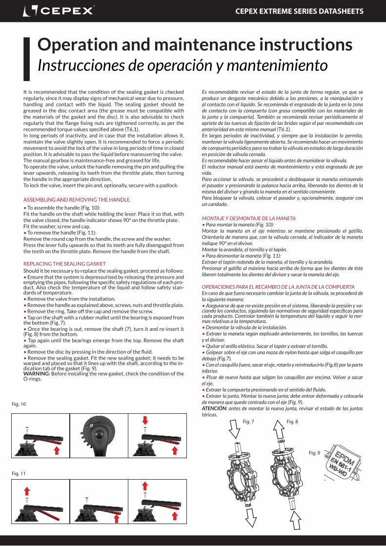
It is recommended that the condition of the sealing gasket is checked regularly, since it may display signs of mechanical wear due to pressure, handling and contact with the liquid. The sealing gasket should be greased in the disc contact area (the grease must be compatible with the materials of the gasket and the disc). It is also advisable to check regularly that the flange fixing nuts are tightened correctly, as per the recommended torque values specified above (T6.1).In long periods of inactivity, and in case that the installation allows it, maintain the valve slightly open. It is recommended to force a periodic movement to avoid the lock of the valve in long periods of time in closed position. It is advisable to pass the liquid before maneuvering the valve.The manual gearbox is maintenance-free and greased for life.To operate the valve, unlock the handle removing the pin and pulling the lever upwards, releasing its teeth from the throttle plate, then turning the handle in the appropriate direction. To lock the valve, insert the pin and, optionally, secure with a padlock.
ASSEMBLING AND REMOVING THE HANDLE
• To assemble the handle (Fig. 10):Fit the handle on the shaft while holding the lever. Place it so that, with the valve closed, the handle indicator shows 90º on the throttle plate .Fit the washer, screw and cap.• To remove the handle (Fig. 11):Remove the round cap from the handle, the screw and the washer.Press the lever fully upwards so that its teeth are fully disengaged from the teeth on the throttle plate. Remove the handle from the shaft.
REPlACING thE SEAlING GASkEtShould it be necessary to replace the sealing gasket, proceed as follows:• Ensure that the system is depressurised by releasing the pressure and emptying the pipes, following the specific safety regulations of each pro-duct. Also check the temperature of the liquid and follow safety stan-dards of temperature.• Remove the valve from the installation.• Remove the handle as explained above, screws, nuts and throttle plate.• Remove the ring. Take off the cap and remove the screw.• Tap on the shaft with a rubber mallet until the bearing is exposed from the bottom (Fig. 7).• Once the bearing is out, remove the shaft (7), turn it and re-insert it (Fig. 8) from the bottom.• Tap again until the bearings emerge from the top. Remove the shaft again.• Remove the disc by pressing in the direction of the fluid.• Remove the sealing gasket. Fit the new sealing gasket; it needs to be warped and placed so that it lines up with the shaft, according to the in-dication tab of the gasket (Fig. 9).WARNING: Before installing the new gasket, check the condition of the O-rings.
Es recomendable revisar el estado de la junta de forma regular, ya que se produce un desgaste mecánico debido a las presiones, a la manipulación y al contacto con el líquido. Se recomienda el engrasado de la junta en la zona de contacto con la compuerta (con grasa compatible con los materiales de la junta y la compuerta). También se recomienda revisar periódicamente el apriete de las tuercas de fijación de las bridas según el par recomendado con anterioridad en este mismo manual (T6.1).En largos periodos de inactividad, y siempre que la instalación lo permita, mantener la válvula ligeramente abierta. Se recomienda hacer un movimiento de compuerta periódico para no trabar la vàlvula en estados de larga duración en posición de válvula cerrada. Es recomendable hacer pasar el líquido antes de maniobrar la válvula.El reductor manual está exento de mantenimiento y está engrasado de por vida.Para accionar la válvula, se procederá a desbloquear la maneta extrayendo el pasador y presionando la palanca hacia arriba, liberando los dientes de la misma del divisor y girando la maneta en el sentido conveniente.Para bloquear la válvula, colocar el pasador y, opcionalmente, asegurar con un candado.
MONTAJE y DESMONTAJE DE LA MANETA• Para montar la maneta (Fig. 10):Montar la maneta en el eje mientras se mantiene presionado el gatillo. Orientarla de manera que, con la válvula cerrada, el indicador de la maneta indique 90º en el divisor.Montar la arandela, el tornillo y el tapón.• Para desmontar la maneta (Fig. 11):Extraer el tapón redondo de la maneta, el tornillo y la arandela.Presionar el gatillo al máximo hacia arriba de forma que los dientes de éste liberen totalmente los dientes del divisor y sacar la maneta del eje.
OPERACIONES PARA EL RECAMBIO DE LA JUNTA DE LA COMPUERTAEn caso de que fuera necesario cambiar la junta de la válvula, se procederá de la siguiente manera:• Asegurarse de que no existe presión en el sistema, liberando la presión y va-ciando los conductos, siguiendo las normativas de seguridad específicas para cada producto. Controlar también la temperatura del líquido y seguir la nor-mas relativas a la temperatura.• Desmontar la válvula de la instalación.• Extraer la maneta según explicado anteriormente, los tornillos, las tuercas y el divisor.• Quitar el anillo elástico. Sacar el tapón y extraer el tornillo.• Golpear sobre el eje con una maza de nylon hasta que salga el casquillo por debajo (Fig.7).• Con el casquillo fuera, sacar el eje, rotarlo y reintroducirlo (Fig.8) por la parte inferior.• Picar de nuevo hasta que salgan los casquillos por encima. Volver a sacar el eje.• Extraer la compuerta presionando en el sentido del fluido.• Extraer la junta. Montar la nueva junta; debe entrar deformada y colocarla de manera que quede centrada con el eje (Fig. 9).ATENCIÓN: antes de montar la nueva junta, revisar el estado de las juntas tóricas.
Operation and maintenance instructionsInstrucciones de operación y mantenimiento
Fig. 7 Fig. 8
Fig. 9
Fig. 10
Fig. 11

CEPEX EXTREME SERIES DATASHEETS
TroubleshootingSolución de problemas
PROBLEMA CAUSA SOLUCIÓN
La compuerta no abre o cierra completamente.
Los manguitos PE-100 no han sido achaflanados correctamente o no son del mismo DN.
Desmontar la válvula y achaflanar los manguitos según T6.2. Comprobar estado de la compuerta y DN de los manguitos.
Elementos extraños en el compartimento (adhesivo, etc.).
Desmontar la válvula y comprobar obstrucciones en la zona de contacto de la compuerta con la junta.
Excesivo par de apertura o cierre. La válvula ha estado mucho tiempo sin maniobrar.
Accionamiento con una llave auxiliar (no la maneta).Desmontar la válvula y lubricar la junta.
Deterioro de la junta por exceso de temperatura o por ataque químico.
Revisar compatibilidad química del líquido con la compuerta y temperatura de trabajo. Cambiar la junta.
Par de embridado excesivo. Embridar según apartado 6.Desalineación entre manguitos y válvula. Desmontar la válvula y volver a montar con
alineación concéntrica (respetar el orden y el par de apriete).
La válvula no presenta una completa estanqueidad en los manguitos de unión.
Desalineación entre manguitos y válvula. Desmontar la válvula y volver a montar con alineación concéntrica (respetar el orden y el par de apriete).
Falta de apriete de los tornillos de embridado. Embridar según apartado 6.La válvula no presenta una completa estanqueidad en la junta.
Elementos químicos inapropiados.Temperatura fuera de valores.Exceso de presión.Conducción de elementos abrasivos.
Comprobar el cumplimiento de las características técnicas de este documento.
Junta dañada. Sustituir la junta.
FAULT POSSIBLE CAUSE FAULT CLEARANCE
The disc does not fully open or close. The sockets were not correctly bevelled. Disassemble the valve and bevel the sockets as indicated in table T6.2.
Foreign materials in the compartment (adhesive, etc.).
Disassemble the valve and check for obstructions in the disc and gasket contact area.
Excessive opening or closing torque. The valve has been inactive for a long time.
Operate with an auxiliary release key (not plastic handle). Disassemble the valve and lubricate the sealing gasket.
Overtemperature or chemical attack cause damage to the gasket.
Check the chemical compatibility of the liquid with the disc and the working temperature. Replace the gasket.
Excessive flange torque. Tighten flanges as indicated in section 6.
Misalignment between sockets and valve. Disassemble the valve and reassemble with concentric alignment (observe the correct tightening sequence and torque).
The valve is not fully watertight at the sockets.
Misalignment between sockets and valve. Disassemble the valve and reassemble with concentric alignment (observe the correct tightening sequence and torque).
Flange screws not tight enough. Tighten flanges as indicated in section 6.
The valve is not completely watertight at the sealing gasket .
Inadequate chemicals.temperature out of range.Excess pressure.Conduction of abrasive elements.
Check compliance with the specifications in this document.
Damaged sealing gasket. Replace the gasket.

CEPEX EXTREME SERIES DATASHEETS
Certificate of compliance pressure equipmentCertificado de conformidad equipos a presión

CEPEX EXTREME SERIES DATASHEETS
Optional accessoriesAccesorios opcionales
LIMIT SWITCH BOXfor butterfly valve Extreme Series
Special configuration with mecanical limit switch box in a manual butterfly valve (with handle) for the remote electronic visualization of the valve position (open/close).
Available for sizes DN40-DN200.
CAJA DE FINAL DE CARRERApara válvulas de mariposa Serie Extreme
Configuración especial con caja de final de carrera en una válvula de mariposa manual (con maneta) para la visualización remota electrónica de la posición de la válvula (abierta/cerrada).
Disponible para las medidas DN40-DN200
DN D CODE
40 50 +LE *
50-65 63-75 +LE *
80 90 +LE *
100 110 +LE *
125 125-140 +LE *
150 160 +LE *
200 200-225 +LE *
* Para pedidos, añadir sufijo al código de la válvula manual, p.e. 66725LE
* For orders, add sufix to the manual valve code, i.e. 66725LE
LIMIT SWITCH BOXfor butterfly valve Extreme Series
Special configuration with mecanical limit switch box in a manual butterfly valve (with gear box) for the remote electronic visualization of the valve position (open/close).
Available for sizes DN50-DN300.
CAJA DE FINAL DE CARRERApara válvulas de mariposa Serie Extreme
Configuración especial con caja de final de carrera en una válvula de mariposa manual (con reductor manual) para la visualización remota electrónica de la posición de la válvula (abierta/cerrada).
Disponible para las medidas DN50-DN300
DN D CODE
40 50 +LF *
50-65 63-75 +LF *
80 90 +LF *
100 110 +LF *
125 125-140 +LF *
150 160 +LF *
200 200-225 +LF *
250 250 +LF *
300 315 +LF ** Para pedidos, añadir sufijo al código de la válvula eje libre, p.e. 61472-
* For orders, add sufix to the bare shaft valve code, i.e. 61472-
Certificate of compliance pressure equipment
CEPEX EXTREME SERIES DATASHEETS
Certificate of compliance pressure equipment
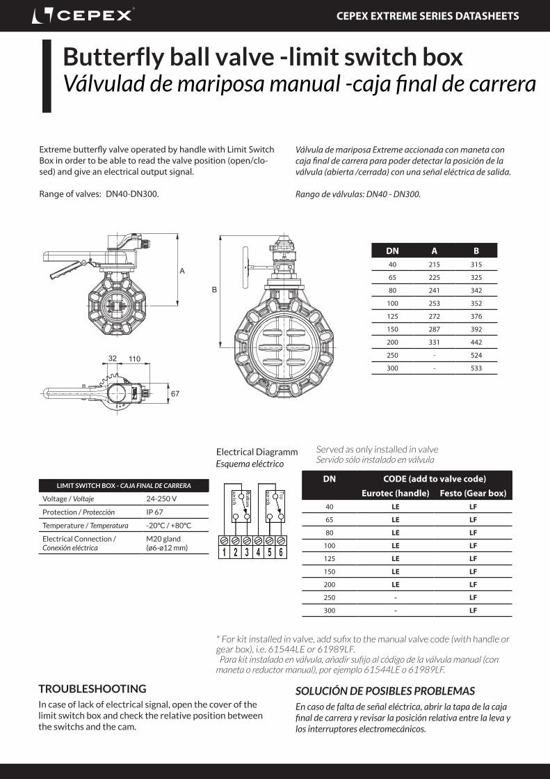
Extreme butterfly valve operated by handle with Limit Switch Box in order to be able to read the valve position (open/clo-sed) and give an electrical output signal.
Range of valves: DN40-DN300.
Válvula de mariposa Extreme accionada con maneta con caja final de carrera para poder detectar la posición de la válvula (abierta /cerrada) con una señal eléctrica de salida.
Rango de válvulas: DN40 - DN300.
TROUBLESHOOTINGIn case of lack of electrical signal, open the cover of the limit switch box and check the relative position between the switchs and the cam.
SOLUCIÓN DE POSIBLES PROBLEMASEn caso de falta de señal eléctrica, abrir la tapa de la caja final de carrera y revisar la posición relativa entre la leva y los interruptores electromecánicos.
Electrical DiagrammEsquema eléctrico
LIMIT SWITCH BOX - CAJA FINAL DE CARRERA
Voltage / Voltaje 24-250 V
Protection / Protección IP 67
Temperature / Temperatura -20ºC / +80ºC
Electrical Connection / Conexión eléctrica
M20 gland (ø6-ø12 mm)
Butterfly ball valve -limit switch boxVálvulad de mariposa manual -caja final de carrera
DN CODE (add to valve code)
Eurotec (handle) Festo (Gear box)40 LE LF
65 LE LF
80 LE LF
100 LE LF
125 LE LF
150 LE LF
200 LE LF
250 - LF
300 - LF
Served as only installed in valveServido sólo instalado en válvula
B
A
67
11032
DN A B40 215 315
65 225 325
80 241 342
100 253 352
125 272 376
150 287 392
200 331 442
250 - 524
300 - 533
* For kit installed in valve, add sufix to the manual valve code (with handle or gear box), i.e. 61544LE or 61989LF. Para kit instalado en válvula, añadir sufijo al código de la válvula manual (con maneta o reductor manual), por ejemplo 61544LE o 61989LF.

CEPEX EXTREME SERIES DATASHEETS
AnnexesAnexos
Some interesting links to know more about the company and the product:
· Website: www,cepexindustrial.com
· Company certifications ISO9001 ISO14001
· Company presentation
· Instructions manual
· Comercial brochure
· Hydraulic concepts and installation advice
Algunos links interesantes para conocer más de la empresa y del producto:
· Página web: www.cepexindustrial.com
· Certificados empresa ISO9001 ISO14001
· Presentación de empresa
· Manual de instrucciones
· Folleto comercial
· Conceptos hidráulicos y consejos de insta-lación
Av. Ramón Ciurans 40 - P.I. Congost P608530 La Garriga (BCN) Spain
Tel: +34 93 870 42 08email: [email protected]
www.cepex.com


![Untitled-2 []€¦ · vÁlvula de descarga 939 vÁlvula de descarga 940 con vista decorativa vÁlvula de descarga dual 942 vÁlvula de descarga 943 con vista decorativa dual](https://static.fdocuments.in/doc/165x107/5f083f2b7e708231d4210fab/untitled-2-vlvula-de-descarga-939-vlvula-de-descarga-940-con-vista-decorativa.jpg)


