Bussmann series UL and data signal surge portection application guide for North America no. 3193
48
Application note 3193 Effective March 2019 Supersedes July 2015 BUSSMANN SERIES For UL Type 1, 2, 3 and Type 4 component assembly, and data signal surge protective devices
Transcript of Bussmann series UL and data signal surge portection application guide for North America no. 3193
Application note 3193Effective March 2019Supersedes July 2015
BUSSMANNSERIES
For UL Type 1, 2, 3 and Type 4 component assembly, and data signal surge protective devices

2
Application Note 3193Effective March 2019
UL Type 1, 2, 3 and Type 4 component assembly, and data signal surge protective devices
Eaton.com/bussmannseries
Contents
Description Page
The need for surge protection
• Case studies for industrial and commercial applications 3• Causes and relevance of transients and surges 3• Damage caused by transients and surges 3
UL SPD Types and NEC locations
• UL SPD standards 4• NEC SPD installation/connection 4• Applying UL SPD Types by NEC location 5
• NEC 285 Type 1 5
• NEC 285 Type 2 5
• NEC 285 Type 3 5
Bussmann series UL power, control and data signal SPD product lineup
• UL Type 1 NEMA 1 and NEMA 4X SPDs• BSPD high surge current capacity Type 1 and Type 2 6
• BSPA Type 1 and Type 2 6
• SurgePOD PRO Type 1 6
• UL DIN-Rail SPDs• High SCCR open Type 1 (black label) 6
• Non SCCR power and control (blue label Type 4 component assembly) 6
• UL 497B DIN-Rail and data signal SPDs• 4 wire universal/twisted pair 6
• RJ45/Ethernet video/data cable 6
UL SPD selection flowchart for ≤ 600 V systems 7
UL SPD types, markets and applications table 8
• Applying UL Type 1, Type 2 and Type 4 component assembly SPDs by surge current capacity (Imax) 8
NEC surge protection requirements 9
Description Page
UL Listed 4th Edition open Type 1 DIN-Rail high SCCR SPDs
Electrical system connections for SPDs 10-11
Installing UL Type 1 and Type 2 SPDs 12
Type 1 NEMA 1 and NEMA 4X UL Listed SPDs
• BSPD 120-400 kA surge current capacity 14-17• BSPA 50-200 kA surge current capacity 18-21• SurgePOD PRO, 40 kA surge current capacity 22-23
• 1-Pole 24-25• 2-Pole 26-27• 3-Pole 28-29• 4-Pole 30-31
UL Recognized Type 4 component assembly DIN-Rail non-SCCR AC/DC power and control SPDs
• 1-Pole UL low voltage power SPDs 32-33• 2-Pole UL low voltage control SPDs 34-35
UL Listed data signal SPDs for telecom and instrumentation data signal applications
• Overview 36• DIN-Rail universal 4 wire SPDs 36-37• DIN-Rail RJ45/Ethernet cable SPD 38
Frequently Asked Questions (FAQs) 39-43
Installing surge protective devices in accordance with NEC Article 240 and Feeder Tap Rule 44
ANSI/UL 1449 short-circuit current rating and NEC Article 285.6 45
SPD glossary 46-47
Online resources — visit Eaton.com/bussmannseries

3
Application Note 3193Effective March 2019
UL Type 1, 2, 3 and Type 4 component assembly, and data signal surge protective devices
Eaton.com/bussmannseries
Internal damage — PCB destroyed by a surge
Service entrance destroyed by a surge
The need for surge protection
Today’s world is full of electronic products and electrical devices that are susceptible to damage from overvoltage surges.
Surges caused by static discharge, capacitive and inductive loads or lightning can quickly destroy sophisticated electronic equipment and components used in industrial and commercial applications. These surges cripple operations – particularly the data and communication systems that virtually every enterprise relies upon today, including UL® 508A panels with their reliance on control circuits.
Also, the NEC requires a listed SPD to be installed on various equipment types including elevators on emergency systems [NEC 620.51(E)], critical operations data systems (NEC 645.18), industrial machinery with safety interlock circuits (NEC 670.6), wind electric systems [NEC 694.7(D)], fire pump controllers (NEC 695.15), emergency panelboards and switchboards (NEC 700.8) and critical operations power systems (NEC 708.20).
We offer a wide selection of Bussmann™ series surge protection products that help assure power quality by eliminating damaging surges.
Case studies and references for industrial and commercial applications
• G.W. Allen and D. Segall with IBM – Two year study at over 200 locations in 25 cities – 88.5% of AC power problems are transient voltage related.
• 2011 Erimar Systems Integration — A lightning strike entered the metals fabricating facility and destroyed $20,000 worth of control panels, electrical infrastructure and Cisco infrastructure. Loss of data system also cost 11 days of production.
• IEEE Emerald Book and NFPA 780 both recommend using surge protection as a part of a building’s lightning protection system. Suppressors at the service entrance only reduce, but not completely eliminate, the high-energy transient. A second surge protective device must be applied upstream of critical equipment. All SPDs should comply with UL 1449 4th Edition or later.
• 1999-2001 Electric Power Research Institute (EPRI) Study – Concluded downtime from power sags, surges and transients cost US industry:• $50 Billion+ in 1999
• $100 Billion+ in 2000
• $200 Billion+ in 2001
• Continues to escalate as more electronic equipment is used
• Plant Services Magazine – 35% of lost production hours can be attributed to transient voltage problems.
• Florida Light and Power 1999 Study — Sources of Facility Surge and Overvoltage Events:• ~60% Internally Generated
• ~40% Externally Generated
Causes and relevance of transients and surges
• Lightning strikes — Large scale impact, high current and voltage, but least common occurrence.
• Power switching — Increasing occurrences:• Utility and customer load switching – Motors, large loads,
faults, capacitor banks, fuse and circuit breaker operation*, etc.
• Source switching — Smart grid, gensets, photovoltaic power systems and wind power generation, etc.
* During overcurrent events, both circuit breakers and fuses can produce arc voltages 2-3 times the system voltage in accordance with the UL standards.
Damage caused by transients and surges
• Disruptive – A voltage transient enters an electronic component and it interprets the transient as a valid logic command, resulting in system lock-up, malfunction, faulty output or corrupted files.
• Dissipative – Associated with short duration repetitive low energy level surges, resulting in equipment failure over time including electronic components, ballasts, motors and controllers, service entrance equipment, panelboards and switchgear.
• Destructive – Associated with high level energy surges, resulting in immediate equipment failure including electronic components, ballasts, motors and controllers, service entrance equipment, panelboards and switchgear.

4
Application Note 3193Effective March 2019
UL Type 1, 2, 3 and Type 4 component assembly, and data signal surge protective devices
Eaton.com/bussmannseries
UL SPD types and NEC locationsBoth UL and the NEC define surge protective device Types, but they are NOT the same. They differ significantly by the following.
UL SPD standards
SURGE PROTECTIVE DEVICES — UL 1449, 4th Edition, Section 1 effective August 20, 2014, states the following on UL Types covering enclosed and open-type Surge Protective Devices (SPDs) designed for repeated limiting of transient voltage surges as specified in the standard on 50 or 60 Hz power circuits not exceeding 1000 V and for PV applications up to 1500 Vdc and designated as follows:
Type 1 — One port, permanently connected SPDs, except for watt-hour meter socket enclosures, intended for installation between the secondary of the service transformer and the line side of the service equipment overcurrent device, as well as the load side, including watt-hour meter socket enclosures and Molded Case SPDs intended to be installed without an external overcurrent protective device. Type 1 SPDs for use in PV systems can be connected between the PV array and the main service disconnect.
Type 2 — Permanently connected SPDs intended for installation on the load side of the service equipment overcurrent device; including SPDs located at the branch panel and Molded Case SPDs.
Type 3 — Point of utilization SPDs, installed at a minimum conductor length of 10 meters (30 feet) from the electrical service panel to the point of utilization, for example cord connected, direct plug-in, receptacle type and SPDs installed at the utilization equipment being protected. See marking in 80.3. The distance (10 meters) is exclusive of conductors provided with or used to attach SPDs.
Type 4 Component Assemblies — Component assembly consisting of one or more Type 5 components together with a disconnect (integral or external) or a means of complying with the limited current tests in 44.4.
Type 1, 2, 3 Component Assemblies — Consists of a Type 4 component assembly with internal or external short circuit protection.
Type 5 — Discrete component surge suppressors, such as MOVs that may be mounted on a PWB, connected by its leads or provided within an enclosure with mounting means and wiring terminations.
NEC SPD installation/connection
NEC Article 285, Surge-Protective Devices (SPDs), 1 kV or Less states the following on where in an electrical system SPDs can be installed and or connected.
II. Installing SPDs
285.13 Type 4 and Other Component Type SPDs. Type 4 component assemblies and other component type SPDs shall only be installed by the equipment manufacturer.
III. Connecting SPDs
285.21 Connection. Where an SPD device is installed, it shall comply with 285.23 through 285.28.
285.23 Type 1 SPDs. Type 1 SPDs shall be installed in accordance with 285.23(A) and (B).
(A) Installation. Type 1 SPDs shall be installed as follows:
(1) Type 1 SPDs shall be permitted to be connected to the supply side of the service disconnect as permitted in 230.82(4) or
(2) Type 1 SPDs shall be permitted to be connected as specified in 285.24.
(B) At the Service. When installed at services, Type 1 SPDs shall be connected to one of the following:
(1) Grounded service conductor
(2) Grounding electrode conductor
(3) Grounding electrode for the service
(4) Equipment grounding terminal in the service equipment
285.24 Type 2 SPDs. Type 2 SPDs shall be installed in accordance with 285.24(A) through (C).
(A) Service-Supplied Building or Structure. Type 2 SPDs shall be connected anywhere on the loadside of a service disconnect overcurrent device required in 230.91, unless installed in accordance with 230.82(8).
(B) Feeder-Supplied Building or Structure. Type 2 SPDs shall be connected at the building or structure anywhere on the loadside of the first overcurrent device at the building or structure.
(C) Separately Derived System. The SPD shall be connected on the loadside of the first overcurrent device in a separately derived system.
285.25 Type 3 SPDs. Type 3 SPDs shall be permitted to be installed on the loadside of branch-circuit overcurrent protection up to the equipment served. If included in the manufacturer’s instructions, the Type 3 SPD connection shall be a minimum 10 m (30 ft) of conductor distance from the service or separately derived system disconnect.
285.26 Conductor Size. Line and grounding conductors shall not be smaller than 14 AWG copper or 12 AWG aluminum.
285.27 Connection Between Conductors. An SPD shall be permitted to be connected between any two conductors — ungrounded conductor(s), grounded conductor, equipment grounding conductor, or grounding electrode conductor. The grounded conductor and the equipment grounding conductor shall be interconnected only by the normal operation of the SPD during a surge.
285.28 Grounding Electrode Conductor Connections and Enclosures. Except as indicated in this article, SPD grounding connections shall be made as specified in Article 250, Part III. Grounding electrode conductors installed in metal enclosures shall comply with 250.64(E).

5
Application Note 3193Effective March 2019
UL Type 1, 2, 3 and Type 4 component assembly, and data signal surge protective devices
Eaton.com/bussmannseries
Applying UL SPD Types by NEC location
Outside and service
entranceFeeders and short
branch circuits
Outlets and long
branch circuits
Pad-mountedtransformer
Note: Only Type 1 SPDspermitted to be installedupstream of the service entrance overcurrent protective device
NEC 285 Type 1
Type 1 SPDs shall be installed as:
(1) Type 1 SPDs shall be permitted to be connected to the supply side of the service disconnect as permitted in 230.82(4) or... as well as the loadside, including watt-hour meter socket enclosures and intended to be installed without an external overcurrent protective device.
(2) Type 1 SPDs shall be permitted to be connected as specified in 285.24.
NEC 285 Type 2 *
Type 2 SPDs shall be installed in accordance with 285.24(A) through (C).
(A) Service-Supplied Building or Structure. Type 2 SPDs shall be connected anywhere on the loadside of a service disconnect overcurrent device required in 230.91, unless installed in accordance with 230.82(8).
(B) Feeder-Supplied Building or Structure. Type 2 SPDs shall be connected at the building or structure anywhere on the loadside of the first overcurrent device at the building or structure.
(C) Separately Derived System. The SPD shall be connected on the loadside of the first overcurrent device in a separately derived system.
NEC 285 Type 3*
Type 3 SPDs shall be permitted to be installed on the loadside of branch-circuit overcurrent protection up to the equipment served. If included in the manufacturer’s instructions, the Type 3 SPD connection shall be a minimum 10 m (30 ft) of conductor distance from the service or separately derived system disconnect.
* Includes Type 2 or Type 4 component assemblies.
Service entrance
UL Type 1 SPD
Lineside or loadside of service entrance
overcurrent protective device
UL open Type 1† SPD
Loadside of service entrance
overcurrent protective device
UL open Type 1† and Type 4† component
assembly SPDs
≥ 30 feet (10 m) from the service entrance
overcurrent protective device
UL Type 1 SPD
≥ 30 feet (10 m) from the service entrance
overcurrent protective device
UL Type 1 SPD
Loadside of service entrance
overcurrent protective device
Feeder circuit
Branch circuit
Device
† Must be installed in an enclosure.

6
Application Note 3193Effective March 2019
UL Type 1, 2, 3 and Type 4 component assembly, and data signal surge protective devices
Eaton.com/bussmannseries
DIN-Rail universal 4 wire
• For nominal 5 and 24 V systems
DIN-Rail RJ45/Ethernet cable
• For nominal voltages up to 48 V
Bussmann series UL power, control and data signal SPD product lineup
This guide suggests which series best meets your needs and applications.
Market Commercial/industrial Light commercial OEMs/UL 508A panel shops
Equipment type Main switchgear, switchboard, motor control center, outdoor load
Distribution panelboard, subpanel, loadcenter Control panel, point of use
NEC SPD requirements* 620.51(E), 645.18, 694.7(D), 700.8 620.51(E), 645.18, 695.15, 700.8, 708.20 670.6, 695.15, 708.20
IEEE exposure category C B A
Typical panel amps Unlimited Up to 4000 Up to 1000 Up to 200 Single-phase, point of use
Peak kA rating per phase 120-400 50—200 40 50 40 / N/A
SCCR (kA) 200 200 200 200 N/A
Nominal voltage 120—600 Vac 120—600 Vac 120—600 Vac 120—600 Vac 24-120 Vac24-200 Vdc
UL 1449/CSA type 1 and 2 1 and 2 1 1 4 component assemblies
UL 1283 EMI/RFI filtering** 50 dB 40 dB N/A N/A N/A
NEMA Enclosure 1 and 4X 4X 4X N/A N/A
Agency information cULus/CSA/RoHS cULus/CSA/RoHS cULus/CSA/RoHS UL Listed open Type 1/CSA/RoHS
UL/cUL/CSA/KEMA/RoHS
Warranty (years) 10 5 2 5 5
Features/mounting Side-mount Side-mount Rear nipple DIN-Rail DIN-Rail
Status indication Yes-LED Yes-LED Yes-LED Yes-Local Yes-Local
OptionsAudible alarm Yes Yes No No No
Form C contacts Yes Yes No Yes - standard Yes - standard
Surge counter Yes No No No No
EMI/RFI filtering Yes Yes No No No
Product family
BSPD BSPA SurgePOD PRO BSPMA BSPM1A/BSPH2A
Data sheet 10209 10661 1003310771 (1-pole), 10772
(2-pole), 10773 (3-pole), 107744 (4-pole)
2056 (1-pole), 2057 (2-pole)
* Product family and rating is dependent upon the application and exposure to surge activity.** Selecting filtering option changes normally Type 1 SPDs to Type 2.† With online registration.†† Available on some models.
Bussmann series UL 497B data signal surge protective devices
These surge protectors complement any power protection SPDs by protecting data signal lines. See pages 36 to 38 for details.

7
Application Note 3193Effective March 2019
UL Type 1, 2, 3 and Type 4 component assembly, and data signal surge protective devices
Eaton.com/bussmannseries
UL SPD selection flowchart for ≤600 V systemsStep 1. Determine location and suitable type*
Service entrance lineside
or loadside of
OCPD?
Step 2. Determine Type 1, and DIN-Rail open Type 1 and Type 4 (Type 2 and 3 applications) SPDs
Inside of
enclosure?
UL 96A std. installation
requirements on lightning protection systems?
Stand alone equipment such as, panelboards,
switchboards or motor control
centers?
Surge current capacity 50 to 200kA
and surge counter required?
Install Type 1 or Type 2 BSPD,
go to pages 14 to 17
UL 508A industrial control
panel?Non UL panel?
Call Applications Engineering toll free 1-855-BUSSMANN
Install Type 1 BSPA, go to pages
18 to 21
Go to Step 2
Yes
No
YesYes
No No No No
NoNo
YesYes
YesYes
SCCR power application?
≤30’ (10 m) from
service entrance disconnect?
24-150 Vac/dc?
Install Type 1 BSPA go to pages
18 to 21 or
Open Type 1 black label SCCR DIN-Rail SPD,
go to pages 24 to 31
75-120 Vac or
100-200 Vdc
Call Applications Engineering toll free 1-855-BUSSMANN
Install Type 4 component assembly blue label
low voltage SPD, go to pages
34 to 35
Yes Yes
No No No
Yes
Yes
Install Type 4 component assembly blue label
low voltage SPD, go to pages
32 to 33
No
* If EMI/RFI filtering is required, select the BSPD or BSPA configuration required for the system.
Start
Start

8
Application Note 3193Effective March 2019
UL Type 1, 2, 3 and Type 4 component assembly, and data signal surge protective devices
Eaton.com/bussmannseries
UL SPD types, markets and applications
Markets
UL TypesUL Listed Type 1 and Type 2 DIN-Rail UL Listed open Type 1 and Recognized Type 4 component assembly
UL Listed Type 1 and Type 2 SPDsSCCR rated 120-600 VacMOV and thermal disconnect technology
UL Listed open Type 1 SPDsSCCR rated black label 120-600 VacMOV technology
Type 4 component assembly power and control blue label SPDs24-120 Vac, 24-200 VdcMOV or hybrid technology
Agriculture • Pump panels requiring SCCR ratings• Service panels • Pump panels requiring SCCR ratings • AC/DC Pump panels not requiring
SCCR ratings
Commercial/institutional
• Elevator control• Emergency generator control• Feeders• Fire pump control• HVAC• Lighting panels• Main switchgear• Motor control centers• Step down transformer primary• UL 508A panels requiring SCCR ratings• UPS
• Elevator control• Emergency generator control• Fire pump control• HVAC• Mission critical panelboards• UPS• UL 508A panels requiring SCCR ratings• VFD
• Elevator control• Emergency generator control• Fire alarm• Fire pump control• HVAC• Security systems• UPS
Contractor • Installation on outside of enclosure or ahead of service entrance disconnect — —
Data centers
• Emergency generator control• Feeders• HVAC• Main switchgear• Power distribution unit• Remote power panel• UPS
• Emergency generator control• HVAC• Power distribution unit• Remote power panel• UPS
• Emergency generator control• HVAC• Servers• UPS
Industrial
• Emergency generator control• HVAC• Lighting panels• Main switchgear• Motor control centers• Step down transformer primary• UL 508A panels requiring SCCR ratings• UPS• VFD
• Conveyor systems• Crane control• HVAC• Power supplies• Step down transformer primary• UL 508A panels requiring SCCR ratings• VFD
• Discrete control• HMI• HVAC• PLCs• Power supplies• Sensors
OEM • Installation on outside of enclosure• UL 508A panels requiring SCCR ratings
• I/Os• PLCs• Power supplies• Step down transformer primary• UL 508A panels requiring SCCR ratings• VFD
• HMI• I/Os• PLCs• Power supplies• Sensors• Step down transformer primary
Oil and gas
• Emergency generator control• Lighting panels• Main switchgear• Motor control centers• Step down transformer primary• UL 508A panels requiring SCCR ratings• UPS• VFD
• Conveyor systems• Crane control• Power supplies• Step down transformer primary• UL 508A panels requiring SCCR ratings• VFD
• Discrete control• HMI• PLCs• Power supplies• Sensors
Residential • Service entrance N/A N/A
UL 508A shops• Installation on outside or inside of
enclosure or ahead of service entrance disconnect
• I/Os• Installation on the lineside of the
enclosure disconnect OCPD• PLC• Power supplies• Step down transformer primary• VFD
• HMI• I/Os• PLCs• Power supplies• Sensors• Step down transformer primary
Waste water/water treatment
• Main switchgear• Motor control centers• UL 508A panels requiring SCCR ratings
• Control panels• UL 508A panels requiring SCCR ratings• VFD
• PLC• Power supplies• Sensors
Applying UL Type 1, Type 2 and Type 4 SPDs by surge current capacity (Imax)
Bussmann series product Installation location Surge current capacity (Imax)BSPD Type 1 and Type 2 Switchboards, service entrance 200 kA to 400 kABSPD Type 2 Large panelboards 120 kA to 200 kABSPA Type 1 and Type 2 Panelboards, control panels 50 kA to 200 kASurgePOD™ PRO Type 1 Panelboards, control panels 40 kA1-, 2-, 3- and 4-pole high SCCR open Type 1 (black label) Control panels 50 kA1-pole non SCCR Type 4 for Type 2 application (blue label) Control panels (power) 40 kA2-pole non SCCR Type 4 for Type 3 application (blue label) Control panels (control) 2-4 kA*
* Total discharge current.
9
Application Note 3193Effective March 2019
UL Type 1, 2, 3 and Type 4 component assembly, and data signal surge protective devices
Eaton.com/bussmannseries
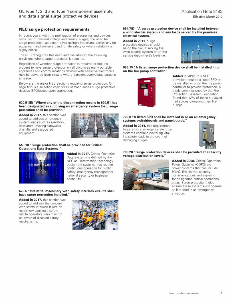
NEC surge protection requirementsIn recent years, with the proliferation of electronics and devices sensitive to transient voltage and current surges, the need for surge protection has become increasingly important, particularly for equipment and systems used for life safety or where reliability is highly critical.
The NEC recognizes this need and has adopted the following provisions where surge protection is required.
Regardless of whether surge protection is required or not, it’s prudent to have surge protection on all circuits as many portable appliances and communications devices with sensitive electronics may be powered from circuits where transient overvoltage surge is an issue.
Below are the major NEC Sections requiring surge protection. On page two is a selection chart for Bussmann series surge protective devices (SPD)based upon application.
620.51(E) “Where any of the disconnecting means in 620.51 has been designated as supplying an emergency system load, surge protection shall be provided.”
Added in 2017, this section was added to address emergency system loads such as elevators, escalators, moving sidewalks, chairlifts and associated equipment.
645.18 “Surge protection shall be provided for Critical Operations Data Systems.”
Added in 2017, Critical Operation Data Systems is defined by the NEC as “Information technology equipment systems that require continuous operation for public safety, emergency management, national security or business continuity.”
670.6 “Industrial machinery with safety interlock circuits shall have surge protection installed.”
Added in 2017, this section was added to address the concern with safety interlock failure on machinery causing a safety risk to operators who may not be aware of disabled safety mechanisms.
694.7(D) “A surge protection device shall be installed between a wind electric system and any loads served by the premises electrical system.”
Added in 2011, surge protective devices should be on the circuit serving the wind electric system or on the service disconnect’s loadside.
695.15 “A listed surge protection device shall be installed in or on the fire pump controller.”
Added in 2017, this NEC provision requires a listed SPD to be installed in or on the fire pump controller to provide protection. A study commissioned by the Fire Protection Research Foundation found that 12% of those surveyed had surges damaging their fire pumps.
700.8 “A listed SPD shall be installed in or on all emergency systems switchboards and panelboards.”
Added in 2014, this requirement helps ensure emergency electrical systems continue powering vital, life-safety loads in the event of damaging surges.
708.20 “Surge protection devices shall be provided at all facility voltage distribution levels.”
Added in 2008, Critical Operation Power Systems (COPS) are power systems that can include HVAC, fire alarms, security, communications and signaling for designated critical operations areas. Surge protection helps ensure these systems will operate as intended in an emergency situation.
10
Application Note 3193Effective March 2019
UL Type 1, 2, 3 and Type 4 component assembly, and data signal surge protective devices
Eaton.com/bussmannseries
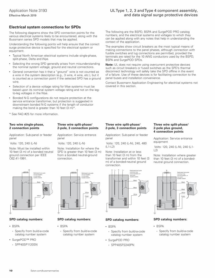
Electrical system connections for SPDsThe following diagrams show the SPD connection points for the various electrical systems likely to be encountered, along with the Bussmann series SPD models that may be applied.
Understanding the following points will help ensure that the correct surge protective device is specified for the electrical system or equipment.• Typical North American electrical systems include single-phase,
split-phase, Delta and Wye.• Selecting the wrong SPD generally arises from misunderstanding
the nominal system voltage, ground and neutral connections.• General convention has it that a “ground” wire is not counted as
a wire in the system description (e.g., 3 wire, 4 wire, etc.), but it is counted as a connection point if the selected SPD has a ground wire.
• Selection of a device voltage rating for Wye systems must be based upon its nominal system voltage rating and not on the leg-to-leg voltages in the Wye.
• Bonded N-G configurations do not require protection at the service entrance transformer, but protection is suggested in downstream bonded N-G systems if the length of conductor making the bond is greater than 10 feet (3 m)*.
* See FAQ #25 for more information.
SPD catalog numbers:
• BSPA
• Specify from build-a-code catalog number system
• SurgePOD™ PRO
• SPP40SP1120SN
White
N
Dedicated one-pole circuit breaker, or one-polefusible switch
Black
G
L1
Two wire single-phase, 2 connection points
Application: Sub-panel or feeder panel
Volts: 120, 240 (L-N)
Note: Must be installed within 10 feet (3 m) of a bonded neutral ground connection per IEEE C62.41-1991.
SPD catalog numbers:
• BSPA
• Specify from build-a-code catalog number system
• SurgePOD PRO
• SPP40SP2240PN
White
Black
N
Dedicated two-pole common trip circuit breaker, or two-pole fusible switch
Black
G
L1 L2
NG L1 L2
Three wire split-phase/ 2-pole, 3 connection points
Application: Sub-panel or feeder panel
Volts: 120, 240 (L-N), 240, 480 (L1-L2)
Note: Installation at or less than 10 feet (3 m) from the transformer and within 10 feet (3 m) of a bonded-neutral ground connection.
SPD catalog numbers:
• BSPA
• Specify from build-a-code catalog number system
White
N
Dedicated one-pole circuit breaker, or one-polefusible switch
Black
G
GreenL1
Three wire split-phase/ 2-pole, 3 connection points
Application: Service entrance panel
Volts: 120, 240 (L-N)
Note: Installation for where the SPD is greater than 10 feet (3 m) from a bonded neutral-ground connection.
SPD catalog numbers:
• BSPA
• Specify from build-a-code catalog number system
White
Black
N
Black
G
GreenL1 L2
Dedicated two-pole common trip circuit breaker, or two-pole fusible switch
Three wire split-phase/ 2-pole plus ground, 4 connection points
Application: Service entrance equipment
Volts: 120, 240 (L-N), 240 (L1-L2)
Note: Installation where greater than 10 feet (3 m) of a bonded-neutral ground connection.
The following are the BSPD, BSPA and SurgePOD PRO catalog numbers, and the electrical systems and voltages to which they can be applied along with any notes that help in understanding the context of the application.
The examples show circuit breakers as the most typical means of making connections to the panel phases, although connection with fusible switches and lug connections are permitted, provided the terminals are rated for the 10 AWG conductors used by the BSPD, BSPA and SurgePOD SPDs.
Note: UL does not require using overcurrent protective devices such as circuit breakers or fused switches as the SPD’s thermal disconnect technology will safely take the SPD offline in the event of a failure. Use of these devices is for facilitating connection to the panel buses and installation convenience.
Contact Bussmann Application Engineering for electrical systems not covered in this section.

11
Application Note 3193Effective March 2019
UL Type 1, 2, 3 and Type 4 component assembly, and data signal surge protective devices
Eaton.com/bussmannseries
SPD catalog numbers:
• BSPA
• Specify from build-a-code catalog number system
White
Black
N
Black
G
GreenL1 L2
Dedicated two-pole common trip circuit breaker, or two-pole fusible switch
NL1 L2
Three wire split-phase/ 2-pole plus ground, 4 connection points
Application: Sub-panel or feeder panel
Volts: 120, 240 (L-N), 240 (L1-L2)
Note: For installation greater than 10 feet (3 m) of a bonded-neutral ground connection.
SPD catalog numbers:
• BSPA
• Specify from build-a-code catalog number system
• BSPD
• Specify from build-a-code catalog number system
White
Black
N
Dedicated three-polecommon trip circuit breaker, or three-pole fusible switch
Black
Black
G
GreenL1 L2 L3
Four wire Wye plus ground, 5 connection points
Application: Service entrance equipment
Volts: 120, 127, 277, 347 (L-N), 208, 220, 480, 600 (L-L)
Note: Common system configuration with Neutral pulled into facility and bonded to ground.
SPD catalog numbers:
• BSPA
• Specify from build-a-code catalog number system
• SurgePOD PRO
• SPP40SP3208WYG
• SPP40SP3480WYG
• SPP40SP3600WYG
Black
Dedicated three-pole common trip circuit breaker, or three-pole fusible switch
Black
Black
G
GreenL1 L2 L3
Three wire Wye plus ground, 4 connection points
Application: Sub-panel or feeder panel
Volts: 208, 480, 600 (L-L)
Note: A common MCC configuration for pumping and water/waste water treatment.
SPD catalog numbers:
• BSPA
• Specify from build-a-code catalog number system
• BSPD
• Specify from build-a-code catalog number system
White
Black
N
Dedicated three-pole common trip circuit breaker, or three-pole fusible switch
Black
Black
G
GreenL1 L2 L3
NL1 L2 L3
Four wire Wye plus ground, 5 connection points
Application: Sub-panel or feeder panel
Volts: 120, 127, 277, 347 (L-N), 208, 220, 480, 600 (L-L)
Note: Common system configuration with Neutral pulled into facility and bonded to ground.
SPD catalog numbers:
• BSPA
• Specify from build-a-code catalog number system
• BSPD
• Specify from build-a-code catalog number system
Black
Dedicated three-pole common trip circuit breaker, or three-pole fusible switch
Black
Black
G
GreenL1 L2 L3
Three wire Delta plus ground, 4 connection points
Application: Service entrance equipment, sub-panel or feeder panel
Volts: 240, 480, 600 (L-L)

12
Application Note 3193Effective March 2019
UL Type 1, 2, 3 and Type 4 component assembly, and data signal surge protective devices
Eaton.com/bussmannseries
Installing UL Type 1 and Type 2 SPDsWhile differences will arise in the installation of different SPD models on various electrical systems and locations inside an electrical system, the following are general procedures and considerations to follow.
At the start of this section are diagrams indicating the connection points for the Type 1 and Type 2 SPDs contained in this guide and the electrical system to which they can be connected.
Installation steps
1. Inspect the electrical panelboard to be sure it is properly grounded in accordance with prevailing code requirements.
2. Inspect the SPD unit to determine:• It has the correct nominal system and MCOV voltage rating
and is the correct configuration for the installation.• It is not damaged; If the unit is damaged or not correct for the
system, do not install it. Secure a proper replacement before proceeding with the installation.
3. Deenergize panelboard and follow established lockout / tagout procedures. Remove panelboard cover(s) to gain access to the interior. Check to make sure the entire panelboard is deenergized before proceeding.
4. Select a location on the panelboard that accommodates mounting the SPD and allows the leads to reach their intended connection points. Be sure the SPD unit can be positioned so that the LED status indicator(s) is visible. A location that permits the shortest lead lengths is preferred.
5. Remove a 3/4” knockout or make a 1-1/16” diameter hole where the SPD is to be mounted.
6. Remove the locknut from the unit and insert leads through the panelboard wall being careful not to damage the conductor insulation. (For NEMA 4X installations, use appropriate gaskets or sealing means to retain the NEMA 4X rating on the installation — see Figure 1.) Reinstall locknut and tighten to specified torque.
Installation option A: using feed through lugs
7. Determine if the lugs are rated for stranded 10 AWG conductors. If lugs are not rated for this size conductor, DO NOT install the SPD unit, or replace lugs with appropriately rated lugs before proceeding, or install the unit using installation option B.
8. Route and trim the leads so they reach their connection points with the least amount of length.
9. Strip the lead ends to lug manufacturer’s specifications, insert them into the appropriate ports and torque to the specified value NOTE: DO NOT install more than one lead into the same lug port.
Go to step 13.
Installation option B: circuit breaker or fused switch
When using a circuit breaker or fused switch, see suggested ampacities in Table A for the SPD family product being installed.
10. Place in the OFF position and install a new, dedicated common trip circuit breaker or fusible switch with fuses sized by SPD family and located as close as possible to where the SPD unit is mounted.
11. Route and trim the leads so they reach their intended connection points with the least amount of length.
12. Strip the lead end to fit the connection points, insert into the terminal lugs and torque to the specified value.
Go to step 13.
Finishing the installation
13. Reinstall the panelboard cover(s).
14. Test the SPD installation by energizing the panelboard and placing the circuit breaker or fusible switch (requires fuses to be installed) in the ON position. Verify the LED status indicators are functioning according to the installed SPD model. If LEDs are not properly displaying for a correctly installed and functioning SPD (per model), see the troubleshooting procedures for possible causes and remedy.
SPD family
Suggested minimum ampacity
Fused switch Circuit breakerSurgePOD PRO (SPP) 30 A 30 ABSPA 60 A 30 ABSPD 100 A 30 A
Table A — Circuit breaker and fused switch sizing guide
Figure 1.
If using conduit, keep the run as straight and short as possible, and avoid using 90 elbows.
NOTE: For optimum performance, trim the leads to the shortest length possible and avoid sharp bends. Make electrical connections appropriate for the application.
Tighten locknut to20.3 lb-in (2.3 N•m)
NEMA 4X installation requires appropriate customer-supplied gasket between the SPD and enclosure wall.

13
Application Note 3193Effective March 2019
UL Type 1, 2, 3 and Type 4 component assembly, and data signal surge protective devices
Eaton.com/bussmannseries
BSPD, BSPA and SurgePOD PRO comparisons
SPD model / color BSPD — grey BSPA — black PRO — grey
Markets Commercial and industrial with high surge current Commercial and industrial Residential, light commercial
and UL 508A panelsProduct warranty* 10 years 10 years 2 yearsSystem types Delta and Wye Single, Split, Delta Single, Split, Delta and Wye
Nominal system voltages 120/208, 240, 277/480, 480, 600
120, 240, 120/240, 480, 120/208, 240/415, 277/480, 347/600, 600
120, 208, 240, 480
Max. continuous operating AC voltage (MCOV) [VC] Sized to nominal voltage (150 V to 840 V)
Sized to nominal voltage (150 V to 840 V)
Sized to nominal voltage (150 V to 550 V)
SCCR 200 kA 200 kA 200 kANominal discharge current (8x20 µs) In 20 kA 20 kA 10 kASurge current capacity (8x20 µs) Imax 120, 200, 300, 400 kA 50, 100, 150, 200 kA 40 kAInstallation connections 3, 5 Wires 3, 5 Wires 2, 3, 4 WiresN-G protection Yes Yes NoResponse time (ns) tA <25ns <25ns <25nsFrequency 50/60 Hz 50/60 Hz 50/60 Hz
Operating status/fault indication One red and green LED per phase
One red and green LED per phase
One bi-color LED Green (Good) / Red (Replace)
Conductor gauge / length 10 AWG stranded copper / 48 inches
10 AWG Stranded copper/ 36 inches
10 AWG Stranded copper/ 18 inches
Mounting Chase nipple (NEMA 1) internal hub (NEMA 4X)
Chase nipple, flush or optional mounting plate
Chase nipple or customer supplied bracket
Enclosure rating NEMA 1 or NEMA 4X NEMA 4X NEMA 4X — UL 94-5 VADegree of protection (installed state) IP20 (finger-safe) IP20 (finger-safe) IP20 (finger-safe)Circuit location Lineside/loadside*** Lineside/loadside*** Lineside/loadside
Standards/agency informationUL Listed 1449 4th Edition Type 1 SPD, UL 1283 Type 2 Recognized, CSA Certified
UL Listed 1449 4th Edition Type 1 SPD, cULus, CSA, RoHS Compliant
UL Listed 1449 4th Edition Type 1 SPD, cULus, RoHS Compliant
Operating temperature -40°C to +50°C -40°C to +60°C -40°C to +65°COperating altitude 16,000 Feet 6561 Feet 12,000 Feet
Options†
Form C contact relay Form C contact relay
—EMI/RFI filter (up to 50 db 10 kHz to 100 MHz) EMI/RFI filter (up to 40 db 10
kHz to 100 MHz)Surge counter
Data sheets 10209 10661 10033
* See SPD Limited Warranty Statement (3A1502) for details at Eaton.com/bussmannseries.† BSPD and BSPA models ordered with Form C contact relay and/or surge counter options are UL Type 2 SPDs and cannot be located on the lineside of the service
entrance overcurrent protective device.

14
Application Note 3193Effective March 2019
UL Type 1, 2, 3 and Type 4 component assembly, and data signal surge protective devices
Eaton.com/bussmannseries
Type 1 NEMA 1 and NEMA 4X UL Listed SPDs
NEMA 4X 304 Stainless Steel enclosure, all surge current capacities
NEMA 1 steel enclosure 120 kA to 400 kA maximum surge current capacity
Catalog number system
The catalog numbering system permits specifying any combination to meet requirements. BSPD 200 480D 2 K
BSPD = Product family
Surge rating per phase
• 120 = 120 kA
• 200 = 200 kA
• 300 = 300 kA
• 400 = 400 kA
Voltage/system code
• 208Y = 120/208 Wye (4W + Gnd)
• 480Y = 277/480 Wye (4W + Gnd)
• 600Y = 347/600 Wye (4W + Gnd)
• 240D = 240 Delta (3W + Gnd)
• 480D = 480 Delta (3W + Gnd)
• 600D = 600 Delta (3W + Gnd)
Configurations
• 1 = Basic
• Green and red LEDs per phase to indicate protection status.
• Green and red LEDs on Wye units to indicate protection status of the neutral-to-ground mode
• 2 = Standard
• Green and red LEDs per phase to indicate protection status
• Green and red LEDs on Wye units to indicate protection status of the neutral-to-ground mode
• Audible alarm with silence button
• Form C contact relay
• EMI/RFI filtering providing up to 50 dB of noise attenuation from 10 kHz to 100 MHz
• 3 = Standard With Surge Counter
• Green and red LEDs per phase to indicate protection status
• Green and red LEDs on Wye units to indicate protection status of the neutral-to-ground mode
• Audible alarm with silence button
• Form C contact relay
• EMI/RFI filtering providing up to 50 dB of noise attenuation from 10 kHz to 100 MHz
• Surge counter with reset button
NEMA enclosures
• K = NEMA 1
• P = NEMA 4X
BSPD NEMA 1 and 4X, Type 1 and 2
Description
BSPD SPDs are UL Listed 1449 4th Edition Type 1 or UL Recognized 1283 5th Edition Type 2 surge protectors, depending on the configuration. The BSPD is available for installation external to an electrical enclosure or panelboard. Application of BSPD units throughout a facility will help ensure that equipment is protected.
BSPD units are available for common Delta and Wye voltage systems in a variety of surge current capacity ratings from 120 kA through 400 kA. Available in three configurations, the BSPD’s configurations and options make it easy to specify units for many electrical applications; including service entrances, distribution switchboards, panelboards and point-of-use.• Basic, Standard and Standard with Surge Counter configurations
UL Listed 1449 4th Edition File E316410 Guide VZCA, CSA Certified Notice 516 File 243397
• Standard and Standard with Surge Counter configurations are also UL Recognized 1283 5th Edition File E316410 Guide VZCA2, CSA Component Acceptance Std. C22.2
• RoHS compliant• Uses Bussmann SurgePOD thermally protected Metal Oxide
Varistor (MOV) technology• 20 kA nominal discharge current (In) rating (maximum rating
assigned by UL)• 120 kA through 400 kA per phase surge current capacity (Imax)
ratings• 200 kA Short-Circuit Current Rating (SCCR)• Two color LED status indicators for each phase on Delta and Wye
units, plus N-G on Wye units• 10-year warranty
Configurations
The BSPD provides users with the option of selecting between three configurations:• Basic (Type 1)• Standard with Form C contact and EMI/RFI filter (Type 2)• Standard with Surge Counter (Type 2)
The appropriate configuration can be specified from the catalog number system based on the application’s requirements or specifications.

15
Application Note 3193Effective March 2019
UL Type 1, 2, 3 and Type 4 component assembly, and data signal surge protective devices
Eaton.com/bussmannseries
BSPD configuration comparisons
Features
Configuration
Basic (Type 1)
Standard (Type 2)
Standard with Surge Counter
(Type 2)Surge protection using MOV technology X X XTwo color LED protection status indicators for each phase X X XTwo color LED protection status indicators for the neutral-ground protection mode (Wye systems only) X X XAudible alarm with silence button X XForm C contact relay X XEMI/RFI filtering, providing up to 50 dB of noise attenuation from 10 kHz to 100 MHz X XSurge counter with reset button X
12.05(306.1)
5.24(133.1)
0.78(19.8)
2.00(50.8)
3.48(88.4)
4.41(112.0)
Ø0.20(Ø5.1)
10.48(266.2)
0.68(17.3)
7.28(184.9)
5.27(133.9)
1.00(25.4)
11.25(285.8)
7.47(189.7)
0.40(10.2)
12.05(306.1)
5.24(133.1)
0.78(19.8)
2.00(50.8)
5.76(146.3)
6.69(169.9)
0.40(10.2)
7.47(189.7)
Ø0.20(Ø5.1)
10.48(266.2)
0.67(17.0)
5.47(138.9)
1.00(25.4)
11.25(285.8)
A B120-200kA 2.60 (66.0) 5.39 (137.0)250-400kA 4.10 (104.1) 7.68 (195.0)
Dimensions — in (mm)
120 kA and 200 kA Units/NEMA 1
300 kA and 400 kA Units/NEMA 1
120 kA to 400 kA Units/NEMA 4X
Form C contact relay wire color codes
Blue/white
Red/white
Orange/white
Common
NO (normally open)
NC (normally closed)

16
Application Note 3193Effective March 2019
UL Type 1, 2, 3 and Type 4 component assembly, and data signal surge protective devices
Eaton.com/bussmannseries
BSPD specifications
Description Specification
Available system voltages
Three-phase Wye 120/208, 277/480 and 347/600
Three-phase Delta 240, 480 and 600
Input power frequency 50/60 Hz
Maximum Continuous Operating Voltage (MCOV)
208Y, and 240D voltage/system type codes 150 L-N,150 L-G, 150 N-G, 300 L-L
480Y Voltage/system type code 320 L-N, 320 L-G, 320 N-G, 640 L-L
600Y Voltage/system type code 420 L-N, 420 L-G, 420 N-G, 840 L-L
480D Voltage/system type code 640 L-G, 640 L-L
600D Voltage/system type code 840 L-G, 840 L-L
Short-Circuit Current Rating (SCCR) 200 kA
Nominal discharge current (In) 20 kA
Surge current capacity per phase (Imax) 120 kA, 200 kA, 300 kA and 400 kA ratings available
SPD Types Type 1 (Basic configuration, can also be used in Type 2 applications) Type 2 (Standard and Standard With Surge Counter configurations)
Enclosure types NEMA 1, NEMA 4X 304 Stainless Steel
Ports 1
SPD Conductor length/gauge 48” (1.22 m) 10 AWG Stranded copper
Form C contact relay (Standard and Standard With Surge Counter configurations only)
Contact ratings 150 Vac or 125 Vdc, 1 A maximum
Lead length/gauge 48 inches (1.22 m) / 14 AWG
Contact logic Power ON, normal state; NO contact = OPEN, N.C. contact = CLOSED Power OFF, fault state; NO contact = CLOSED, N.C. contact = OPEN
Power consumption
Basic configuration
208Y and 240D voltage/system type codes 0.5 W
480Y and 480D voltage/system type codes 1.1 W
600Y and 600D voltage/system type codes 1.3 W
Standard and Standard with Surge Counter configurations
208Y and 240D voltage/system type codes 0.6 W
480Y, and 480D voltage/system type codes 1.7 W
600Y and 600D voltage/system type codes 2.1 W
Protection modes Three-phase Delta; L-G, L-L Three-phase Wye; L-N, L-G, N-G, L-L
Operating temperature / humidity -40 to +50°C (-40 to +122°F) / 5% to 95%, non-condensing
Operating altitude — ft (m) 16,000 (5000)
EMI/RFI filtering attenuation Up to 50 dB from 10 kHz to 100 MHz (Standard and Standard With Surge Counter configurations)
Weight — lbs (kg) NEMA 1: 120-200 kA - 6.8 (3.1), 300-400 kA -13.5 (6.1) NEMA 4X: 120-200 kA - 14.6 (6.6), 300-400 kA - 21.0 (9.5)
Agency information
- Basic, Standard and Standard with Surge Counter configurations UL Listed 1449 4th Edition File E316410 Guide VZCA, CSA Certified Notice 516 File 243397
- Standard and Standard with Surge Counter configurations are also UL Recognized 1283 5th Edition File E316410 Guide VZCA2, CSA Component Acceptance Std. C22.2 No. 8-M1986 File 243397
RoHS compliant Yes
Seismic withstand capability Meets or exceeds the requirements specific to I.B.C. 2006, C.B.C. 2007 and U.B.C. Zone 4
Warranty 10 Years (see warranty statement 3A1502 for details at Eaton.com/bussmannseries)

17
Application Note 3193Effective March 2019
UL Type 1, 2, 3 and Type 4 component assembly, and data signal surge protective devices
Eaton.com/bussmannseries
ANSI/UL 1449 4th Edition voltage protection ratings
Voltage Protection Rating (VPR) data for all units is included in the following tables, The data varies based upon the configuration and NEMA enclosure. VPR values for the Basic configurations are on the left-hand side of the page. Tables on the right-hand side contain VPR values for the Standard or Standard with Surge Counter configurations.
NEMA 1 enclosures
Basic (catalog numbers ending 1K)
Voltage/system codeProtection mode
L-N L-G N-G L-L120-200 kA208Y 700 700 700 1200480Y 1200 1200 1200 2000600Y 1500 1500 1500 2500240D — 1000 — 1000480D — 2000 — 2500600D — 2500 — 2500300 kA208Y 700 700 700 1000480Y 1200 1200 1200 1800600Y 1500 1500 1500 2500240D — 1000 — 1000480D — 1800 — 2000600D — 2500 — 2500400 kA208Y 700 700 700 1000480Y 1200 1200 1200 1800600Y 1500 1500 1500 2500240D — 1000 — 1000480D — 1800 — 2000600D — 2500 — 2500
Standard or standard w/ surge counter (catalog numbers ending 2K/3K)
Voltage/system codeProtection mode
L-N L-G N-G L-L120-200 kA208Y 600 800 600 1000480Y 1200 1200 1200 1800600Y 1500 1500 1500 2500240D — 1000 — 1000480D — 2500 — 2500600D — 2500 — 2500300 kA208Y 600 700 600 1000480Y 1000 1200 1000 1800600Y 1500 1500 1500 2500240D — 1000 — 1000480D — 1800 — 2000600D — 2500 — 2500400 kA208Y 600 700 600 1000480Y 1000 1200 1000 1800600Y 1500 1500 1500 2500240D — 1000 — 1000480D — 1800 — 2000600D — 2500 — 2500
NEMA 4X enclosures
Basic (catalog numbers ending 1P)
Voltage/system codeProtection mode
L-N L-G N-G L-L120–200 kA208Y 700 800 700 1200480Y 1200 1200 1000 2000600Y 1500 1500 1500 2500240D — 1000 — 1000480D — 2000 — 2500600D — 2500 — 2500300 kA208Y 700 800 700 1200480Y 1200 1200 1200 2000600Y 1500 1500 1500 2500240D — 1000 — 1000480D — 1800 — 2000600D — 2500 — 2500400 kA208Y 700 800 700 1200480Y 1200 1200 1200 2000600Y 1500 1500 1500 2500240D — 1000 — 1000480D — 1800 — 2000600D — 2500 — 2500
Standard or standard w/ surge counter (catalog numbers ending 2P/3P)
Voltage/system codeProtection mode
L-N L-G N-G L-L120–200 kA208Y 900 900 700 1500480Y 1200 1200 1000 2500600Y 1500 1500 1500 2500240D — 1000 — 1000480D — 2500 — 2500600D — 2500 — 2500300 kA208Y 800 900 700 1500480Y 1200 1200 1000 2000600Y 1500 1500 1500 2500240D — 1000 — 1000480D — 2000 — 2000600D — 2500 — 2500400 kA208Y 800 900 700 1500480Y 1200 1200 1000 2000600Y 1500 1500 1500 2500240D — 1000 — 1000480D — 2000 — 2000600D — 2500 — 2500
18
Application Note 3193Effective March 2019
UL Type 1, 2, 3 and Type 4 component assembly, and data signal surge protective devices
Eaton.com/bussmannseries
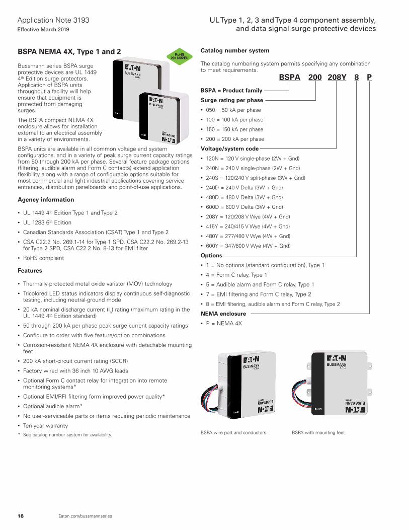
BSPA NEMA 4X, Type 1 and 2
Bussmann series BSPA surge protective devices are UL 1449 4th Edition surge protectors. Application of BSPA units throughout a facility will help ensure that equipment is protected from damaging surges.
The BSPA compact NEMA 4X enclosure allows for installation external to an electrical assembly in a variety of environments.
BSPA units are available in all common voltage and system configurations, and in a variety of peak surge current capacity ratings from 50 through 200 kA per phase. Several feature package options (filtering, audible alarm and Form C contacts) extend application flexibility along with a range of configurable options suitable for most commercial and light industrial applications covering service entrances, distribution panelboards and point-of-use applications.
Agency information
• UL 1449 4th Edition Type 1 and Type 2
• UL 1283 6th Edition
• Canadian Standards Association (CSAT) Type 1 and Type 2
• CSA C22.2 No. 269.1-14 for Type 1 SPD, CSA C22.2 No. 269.2-13 for Type 2 SPD, CSA C22.2 No. 8-13 for EMI filter
• RoHS compliant
Features
• Thermally-protected metal oxide varistor (MOV) technology
• Tricolored LED status indicators display continuous self-diagnostic testing, including neutral-ground mode
• 20 kA nominal discharge current (In) rating (maximum rating in the UL 1449 4th Edition standard)
• 50 through 200 kA per phase peak surge current capacity ratings
• Configure to order with five feature/option combinations
• Corrosion-resistant NEMA 4X enclosure with detachable mounting feet
• 200 kA short-circuit current rating (SCCR)
• Factory wired with 36 inch 10 AWG leads
• Optional Form C contact relay for integration into remote monitoring systems*
• Optional EMI/RFI filtering form improved power quality*
• Optional audible alarm*
• No user-serviceable parts or items requiring periodic maintenance
• Ten-year warranty
* See catalog number system for availability.
Catalog number system
The catalog numbering system permits specifying any combination to meet requirements. BSPA 200 208Y 8 P
BSPA = Product family
Surge rating per phase
• 050 = 50 kA per phase
• 100 = 100 kA per phase
• 150 = 150 kA per phase
• 200 = 200 kA per phase
Voltage/system code
• 120N = 120 V single-phase (2W + Gnd)
• 240N = 240 V single-phase (2W + Gnd)
• 240S = 120/240 V split-phase (3W + Gnd)
• 240D = 240 V Delta (3W + Gnd)
• 480D = 480 V Delta (3W + Gnd)
• 600D = 600 V Delta (3W + Gnd)
• 208Y = 120/208 V Wye (4W + Gnd)
• 415Y = 240/415 V Wye (4W + Gnd)
• 480Y = 277/480 V Wye (4W + Gnd)
• 600Y = 347/600 V Wye (4W + Gnd)
Options
• 1 = No options (standard configuration), Type 1
• 4 = Form C relay, Type 1
• 5 = Audible alarm and Form C relay, Type 1
• 7 = EMI filtering and Form C relay, Type 2
• 8 = EMI filtering, audible alarm and Form C relay, Type 2
NEMA enclosure
• P = NEMA 4X
BSPA with mounting feetBSPA wire port and conductors
2011/65/EU

19
Application Note 3193Effective March 2019
UL Type 1, 2, 3 and Type 4 component assembly, and data signal surge protective devices
Eaton.com/bussmannseries
BSPA configurations
The BSPA allows for selecting along with the standard features the audible alarm, Form C relay contacts and EMI/RFI filtering options shown in table 1.
Configurable features
Feature Standard OptionsSurge protection using thermally protected MOV technology •
Tricolored LED protection status indicators for each phase •
Tricolored LED protection status indicators for the neutral-ground protection mode •
Audible alarm •Form C relay contact •EMI/RFI filtering, for up to 40 dB of noise attenuation from 10 kHz to 100 MHz* •
* Available on Type 2 SPD units only.
Tricolored LED status indicators
These LED indicators show continuous self-diagnostic testing, including neutral-ground mode and display:
• Green—Fully protected
• Yellow—Loss of neutral-to-ground protection
• Red—Loss of protection
Voltage protection ratings per ANSI/UL 1449 4th Edition
Voltage code
Protection mode
L–N L–G N–G L–L
50 kA unit VPR
120N 700 1200 700 —
240N 1200 2000 1500 —
240S 700 1200 700 1200
208Y 700 1200 700 1200
415Y 1200 2000 1500 2000
480Y 1200 2000 1500 2000
600Y 1500 1500 1500 2500
240D — 1000 — 1000
480D — 2000 — 2500
600D — 2500 — 2500
100 kA unit VPR
120N 600 600 600 —
240N 1200 1200 1200 —
240S 600 600 600 1000
208Y 600 600 600 1000
415Y 1200 1200 1200 2000
480Y 1200 1200 1200 2000
600Y 1500 1500 1500 2500
240D — 1000 — 1000
480D — 2000 — 2500
600D — 2500 — 2500
150-200 kA unit VPR
120N 700 700 700 —
240N 1000 1200 1000 —
240S 700 700 700 1200
208Y 700 700 700 1200
415Y 1200 1200 1200 2000
480Y 1200 1200 1200 2000
600Y 1500 1500 1500 2500
240D — 1000 — 1000
480D — 1800 — 2000
600D — 2500 — 2500
LED protection status indicators showing full protection and phase faults
Enclosure ratings, options, dimensions and weights
The BSPA NEMA 4X enclosure is supplied with mounting feet to facilitate installation in a variety of applications. There are two enclosure sizes, P1 and P2, dependent on the voltage code and surge rating.
Available optional equipment
Available option Catalog no.Flush mount plate for P1 enclosure BSPA-FLUSHPLT1Flush mount plate for P2 enclosure BSPA-FLUSHPLT2
BSPA voltage configurations per enclosure size*
P1 enclosure P2 enclosureVoltage code kA Voltage code kA
120N/240N 50–200 240S120–200240S
50-100208Y/415Y/480Y/600Y
208Y/415Y/480Y/600Y 240D/480D240D/480D 600D 50–200
* See catalog number system for voltage code details.

20
Application Note 3193Effective March 2019
UL Type 1, 2, 3 and Type 4 component assembly, and data signal surge protective devices
Eaton.com/bussmannseries
BSPA specifications
Description Value
LeadsLength 36”Size 10 AWG stranded copper
Mounting Chase nipple/panel (with mounting feet)Peak surge current capacity ratings available 50, 100, 150, 200 kA per phaseNominal discharge current (In) 20 kAShort-circuit current rating (SCCR) 200 kASingle-phase voltages available (2W + Gnd) 120, 240Split-phase voltages available (3W + Gnd) 120/240Three-phase Wye system voltages available (4W + Gnd) 120/208, 240/415, 277/480, 347/600Three-phase Delta system voltages available (3W + Gnd) 240, 480, 600Input power frequency 50/60 Hz
Protection modes
Single–phase L–N, N–G, L–GSplit–phase L–N, N–G, L–G, L–LWye L–N, N–G, L–G, L–LDelta L–G, L–L
Maximum continuous operating voltage (MCOV):
Voltage code120N 150 L–N, 150 L–G, 150 N–G240N 320 L–N, 320 L–G, 320 N–G240S, 208Y 150 L–N, 150 L–G, 150 N–G, 300 L–L415Y, 480Y 320 L–N, 320 L–G, 320 N–G, 640 L–L600Y 420 L–N, 420 L–G, 420 N–G, 840 L–L240D 320 L–G, 300 L–L480D 550 L–G, 640 L–L600D 840 L–G, 840 L–L
Ports 1Operating and storage temperature –40°F to +140°F (–40°C to +60°C)Operating humidity 5% through 95%, non-condensingOperating altitude Up to 2000 m (6561 ft)
Agency informationUL 1449 4th Edition, UL 1283 6th Edition, CSA C22.2 No. 269.1-14 for Type 1 SPD, CSA C22.2 No. 269.2-13 for Type 2 SPD, CSA C22.2 No. 8-13 for EMI filter
Durability/repetitive strike test Passed 12,000 strikes to ANSI/IEEE C62.41 (20 kV, 10 kA) Category C waveform
SPD type UL 1449 4th Edition and CSA Type 1 and Type 2 SPD (dependent on feature options)
Enclosure dimensions and weights Refer to Figure 1 and Figure 3 for enclosure dimensions and weightsEnclosure rating NEMA 4X enclosure*Form C relay contact ratings 2 A at 30 Vdc or 250 Vac
Form C relay contact logicPower ON, normal state—NO contact = open, NC contact = closedPower OFF or fault state—NO contact = closed, NC contact = open
EMI/RFI filtering attenuation Up to 40 dB from 10 kHz to 100 MHzRoHS compliant YesWarranty Ten years standard
* Mounting feet required to achieve NEMA 4X rating.

21
Application Note 3193Effective March 2019
UL Type 1, 2, 3 and Type 4 component assembly, and data signal surge protective devices
Eaton.com/bussmannseries
P1 enclosure, NEMA 4X with mounting feet dimensions, weight = 2.5 lb
Optional flush mount plate for P1 enclosure (catalog number BSPA-FLUSHPLT1)
P2 enclosure, NEMA 4X with mounting feet dimensions, weight = 4 lb
Optional flush mount plate for P2 enclosure (catalog number BSPA-FLUSHPLT2)
0.16 (4.1)Mounting feet
(included)
3.19(81.0)
7.13 (181.2)
Overall baseincluding
stabilization ribs5.56 (141.2)0.75 (19.1)
3.75(95.3)
6.62 (168.1)
5.50 (139.6)Lid
1.00 (25.4)
6.00(152.3)
Lid
3/4-14 NPSexternal thread
Locknut
36-inchlong wires
Mounting feet(included)
1.12 (28.5)
4x #8 [m 4]Flathead screw(not included)
6.67 8.48(215.4)
10.25(260.4)
11.50(292.1)
7.48 (190.0)
9.25 (235.0)10.50 (266.7)
4X Ø0.223
0.80(20.3)
(169.4)
0.0747 THK
1.51(38.4)
1.51(38.4)
8.62 (219.0)7.50 (190.5) Lid
9.13 (232.0)
7.56 (192.0)overall base including
stabilization ribs0.75 (19.1)
3.19(81.1)
0.16 (4.1)mounting feet
(included)
8.50(215.9)
Lid
1.00 (25.4)
4x #8 (m4)Flathead screw(not included)
3/4-14 NPSexternal thread
Locknut
Mounting feet(included)
36-inchlong wires
3.75(95.3)
2.38(60.4)
5.48 (139.2)
5.98(151.2)
7.75(196.9)
9.00(228.6)
4X Ø0.223
5.48 (139.2)
7.25 (184.2)8.50 (215.9)
0.80(20.3)
4.17(105.9)
0.0747 THK
1.51(38.4)
1.51(38.4)
Dimensions — in (mm)

22
Application Note 3193Effective March 2019
UL Type 1, 2, 3 and Type 4 component assembly, and data signal surge protective devices
Eaton.com/bussmannseries
SurgePOD PRO NEMA 4X, Type 1Description
Bussmann series SurgePOD PRO is a Type 1 UL Listed 1449 4th Edition surge protective device suitable for installation on both the lineside or loadside of the service entrance overcurrent protective device.
Available in popular voltage and system specific versions to match common residential and light commercial electrical system and equipment requirements, the SurgePOD PRO delivers superior surge protection using MOV thermal disconnect technology.
Parallel connection to the electrical system permits the SurgePOD PRO SPD to be installed on any ampacity panel.• Type 1 UL Listed 1449 4th Edition SPDs are easily selected and
installed on the lineside or loadside of the service entrance overcurrent protective device
• Voltage specific models precisely match and protect electrical systems and equipment better than “one-size-fits-all” SPDs
• Thermal disconnect technology eliminates the need for additional fusing
• Compact NEMA 4X enclosure for indoor or outdoor applications• easyID™ LED status indicator provides surge protection status at
a glance
Dimensions — in
2-1/16” 2-1/16”
1-11/16”
1-11/16”
4-1/8”
3-3/16”
4-1/16”3-3/8”
7/8”
Ø1-1/16”
Available catalog numbers
Catalog no.SPP40SP1120SN SPP40SP3240DLG SPP40SP3208WYGSPP40SP2240PN SPP40SP3480DLG SPP40SP3480WYGSPP40SP3600WYG
See catalog number explanation below for details.
Catalog number explanation
SPP 40S Px xxx xxx
SPP = Product series
Surge rating• 40 kA surge current capacity
Number of wires• P1 = 1, P2 = 2, P3 = 3
System voltage (Vac)• 120, 208, 240, 480, 600
System type/wires and connection points• SN = Single-phase 2 wire, 2 connection points• PN = Split-phase 3 wire , 3 connection points• DLG = Three-phase Delta 3 wire + Gnd, 4 connection points• WYG = Three-phase Wye 3 wire, 4 connection points
easyID LED status indicatorThe easyID LED status indicator will illuminate when the unit is properly installed and the system or equipment being protected is energized. The following LED color/status indicates:
GREEN LED = Good
The circuit is energized and protected.
RED LED = Replace
The circuit is energized and unprotected.
The unit needs replacing.
LED is Out / Unlit:
• The circuit is most likely deenergized• The unit’s leads are disconnected• The unit is damaged
Authorized personnel should follow all prescribed lockout/tagout and safety procedures in troubleshooting the cause for the above conditions. Opening SurgePOD PRO enclosure will void the warranty.

23
Application Note 3193Effective March 2019
UL Type 1, 2, 3 and Type 4 component assembly, and data signal surge protective devices
Eaton.com/bussmannseries
SurgePOD PRO specifications
Catalog no. Nominal system voltageMax. continuous operating AC
voltage (MCOV) (VC) System type Connection points
SPP40SP1120SN 120 150 Single-phase 2 wire 2
SPP40SP2240PN 120/240 150 Split-phase 3 wire 3
SPP40SP3240DLG 240 320 Three-phase Delta 3 wire + Gnd 4
SPP40SP3480DLG 480 550 Three-phase Delta 3 wire + Gnd 4
SPP40SP3208WYG 208 150 Three-phase Wye 3 wire + Gnd 4
SPP40SP3480WYG 480 320 Three-phase Wye 3 wire + Gnd 4
SPP40SP3600WYG* 600 420 Three-phase Wye 3 wire + Gnd 4
* Not CSA Certified.
Specifications (for all SurgePOD PRO units) ValuesShort-Circuit Current Rating (SCCR) 200 kANominal discharge current (8x20 µs) (In) 10 kASurge current capacity (8x20 µs) (Imax) 40 kAResponse time (ns) (tA) <25nsFrequency 50/60 HzOperating state/fault indication Bi-color LED — green (good) / red (replace)Conductor length / gauge 18 inches, 10 AWG stranded tinned copperMounting Chase nipple / bracket*Enclosure / flammability ratings NEMA 4X — UL 94-5 VADegree of protection (installed state) IP20 (finger-safe)SPD install location Indoor/outdoorCircuit location Lineside or loadside of service entrance overcurrent protective deviceOperating temperature -40°C to +65°CMaximum operating altitude 12,000 feetAgency information UL Listed, CSA Certified, RoHS compliantStandard UL Type 1 1449 4th Edition SPDWarranty Two years**
* Customer-supplied bracket.** See Limited Warranty Statement 3A1502 for details at Eaton.com/bussmannseries.
Voltage protection ratings
Catalog no.Nominal system
voltage MCOV (VC)Voltage Protection Ratings (VPR)
L-N L-L L-GSPP40SP1120SN 120 150 700 — —SPP40SP2240PN 120/240 150 700 1200 —SPP40SP3240DLG 240 320 — 2500 1200SPP40SP3480DLG 480 550 — 3000 1800SPP40SP3208WYG 208 150† — 1200 700SPP40SP3480WYG 480 320† — 2500 1200SPP40SP3600WYG 600 420† — 2500 1500
† SPD voltages are measured from Line-to-Neutral, or Line-to-Ground on systems where there is no neutral present. These units do not have a line-to-neutral, so the line-to-ground voltage is 120 V for the 208 V Wye L-G and 277 V for the 480 V L-G, making the normal voltage applied to the unit less than the MCOV values listed in the table.
24
Application Note 3193Effective March 2019
UL Type 1, 2, 3 and Type 4 component assembly, and data signal surge protective devices
Eaton.com/bussmannseries
2011/65/EU
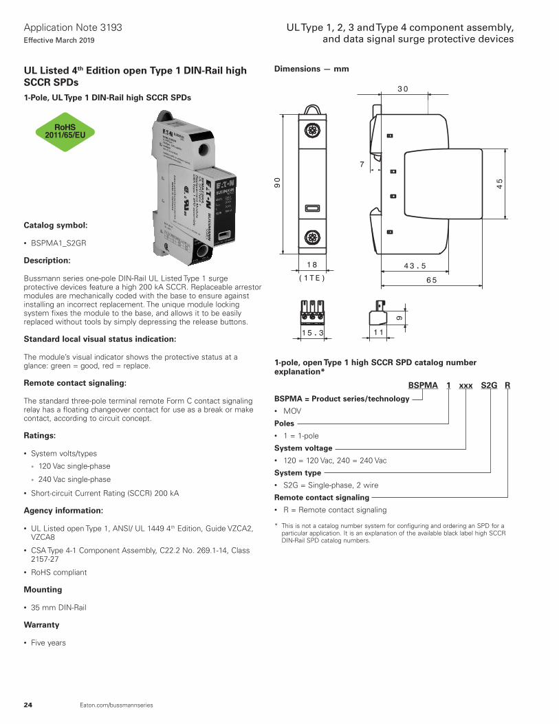
UL Listed 4th Edition open Type 1 DIN-Rail high SCCR SPDs1-Pole, UL Type 1 DIN-Rail high SCCR SPDs
Catalog symbol:
• BSPMA1_S2GR
Description:
Bussmann series one-pole DIN-Rail UL Listed Type 1 surge protective devices feature a high 200 kA SCCR. Replaceable arrestor modules are mechanically coded with the base to ensure against installing an incorrect replacement. The unique module locking system fixes the module to the base, and allows it to be easily replaced without tools by simply depressing the release buttons.
Standard local visual status indication:
The module’s visual indicator shows the protective status at a glance: green = good, red = replace.
Remote contact signaling:
The standard three-pole terminal remote Form C contact signaling relay has a floating changeover contact for use as a break or make contact, according to circuit concept.
Ratings:
• System volts/types
• 120 Vac single-phase
• 240 Vac single-phase
• Short-circuit Current Rating (SCCR) 200 kA
Agency information:
• UL Listed open Type 1, ANSI/ UL 1449 4th Edition, Guide VZCA2, VZCA8
• CSA Type 4-1 Component Assembly, C22.2 No. 269.1-14, Class 2157-27
• RoHS compliant
Mounting
• 35 mm DIN-Rail
Warranty
• Five years
Dimensions — mm
1-pole, open Type 1 high SCCR SPD catalog number explanation*
BSPMA 1 xxx S2G R
BSPMA = Product series/technology• MOV
Poles• 1 = 1-pole
System voltage• 120 = 120 Vac, 240 = 240 Vac
System type• S2G = Single-phase, 2 wire
Remote contact signaling• R = Remote contact signaling
* This is not a catalog number system for configuring and ordering an SPD for a particular application. It is an explanation of the available black label high SCCR DIN-Rail SPD catalog numbers.

25
Application Note 3193Effective March 2019
UL Type 1, 2, 3 and Type 4 component assembly, and data signal surge protective devices
Eaton.com/bussmannseries
Typical installation/system application:
L1
N
L1
L3
L2N
Specifications/ordering informationSystem voltage/type 120 Vac single-phase 240 Vac single-phaseCatalog number BSPMA1120S2GR BSPMA1240S2GRReplacement module catalog number (qty.) BPMA230UL (1) BPMA385UL (1)SPD class per ANSI/UL 1449 4th Ed. Open-Type 1 SPDSPD class per CSA C22.2 No. 269.1-14 Type 4-1 Component AssemblyNominal system voltage (UN) [L-N/L-G] 127 Vac 277 VacNominal power frequency 50 / 60 HzMax. continuous operating voltage AC (MCOV) [L-L] 230 Vac 385 VacNominal discharge current (In) (8x20 µs) 20 kAMax. discharge current (Imax) (8/20) 50 kAVoltage Protection Rating (VPR) [L-L] 700 Vpk 1200 Vpk
Short Circuit Current Rating (SCCR) 200 kAOperating temperature range (TU) °F (°C) -31 to 185 (-35 to 85)Operating state / fault indication Green = good ; Red = replaceWire range (60/75°C Cu, solid/stranded) 2-14 AWG (2.5-35 mm2)Terminal torque — lb-in (N•m) 35-45 (4-5.1)Mounting 35 mm DIN-Rail per EN 60715Enclosure material Thermoplastic, UL 94 V0Protection IP20 (finger-safe)Capacity 1 module(s), DIN 43880Agency information UL Listed, Guide VZCA, VZCA7/CSA Component Acceptance Class 2157-27, RoHSWeight — oz (g) 4.13 (117) 4.44 (126)Contact signalingSignaling type Floating (dry), Form C (SPDT)NEC Circuits NEC Class 2 circuits onlySwitching capacity AC (DC) 250 V/5 A (250 V/0.1 A, 125 V/0.2 A, 75 V/0.5 A)Wire range (60/75°C Cu, solid/stranded) 16-22 AWG (1.5-0.34 mm2)Terminal torque — lb-in (N•m) 1.8 (0.2)

26
Application Note 3193Effective March 2019
UL Type 1, 2, 3 and Type 4 component assembly, and data signal surge protective devices
Eaton.com/bussmannseries
2-Pole, UL Type 1 DIN-Rail high SCCR SPDs
Catalog symbol:
• BSPMA2_S3GR
Description:
Bussmann series two-pole DIN-Rail UL Listed Type 1 surge protective devices feature a high 200 kA SCCR. Replaceable arrestor modules are mechanically coded with the base to ensure against installing an incorrect replacement. The unique module locking system fixes the module to the base, and allows it to be easily replaced without tools by simply depressing the release buttons.
Standard local visual status indication:
The module’s visual indicator shows the protective status at a glance: green = good, red = replace.
Remote contact signaling:
The standard three-pole terminal remote Form C contact sig-naling relay has a floating changeover contact for use as a break or make contact, according to circuit concept.
Ratings:
• System volts/types
• 120/240 Vac split-phase
• 240/480 Vac split-phase
• Short-circuit Current Rating (SCCR) 200 kA
Agency information:
• UL Listed open Type 1, ANSI/ UL 1449 4th Edition, Guide VZCA2, VZCA8
• CSA Type 4-1 Component Assembly, C22.2 No. 269.1-14, Class 2157-27
• RoHS compliant
Mounting
• 35 mm DIN-Rail
Warranty
• Five years
Dimensions — mm
30
45
43.5
65
90
367
15.3 11
9
2011/65/EU
2-pole, open Type 1 high SCCR SPD catalog number explanation*
BSPMA 2 xxx S3G R
BSPMA = Product series/technology• MOV
Poles• 2 = 2-pole
System voltage• 240 = 240 Vac, 480 = 480 Vac
System type• S3G = Single/split-phase, 2 or 3 wire
Remote contact signaling• R = Remote contact signaling
* This is not a catalog number system for configuring and ordering an SPD for a particular application. It is an explanation of the available black label high SCCR DIN-Rail SPD catalog numbers.

27
Application Note 3193Effective March 2019
UL Type 1, 2, 3 and Type 4 component assembly, and data signal surge protective devices
Eaton.com/bussmannseries
Typical installation/system application:
L1
L2
N
Gnd
L1
L2
Gnd
L1
L2
Gnd
L1
L3
L2
N
Specifications/ordering informationSystem voltage/type 120/240 Vac split-phase 240/480 Vac split-phaseCatalog number BSPMA2240S3GR BSPMA2480S3GRReplacement module catalog number (qty.) BPMA230UL (2) BPMA385UL (2)SPD class per ANSI/UL 1449 4th Ed. Open-Type 1 SPDSPD class per CSA C22.2 No. 269.1-14 Type 4-1 Component AssemblyNominal system voltage (UN) [L-G] / [L-L] 127 Vac / 254 Vac 240 Vac / 480 VacNominal power frequency 50 / 60 HzMax. continuous operating voltage AC (MCOV) [L-G] / [L-L] 230 Vac / 460 Vac 385 Vac / 770 VacNominal discharge current (In) (8x20 µs) 20 kAMax. discharge current (Imax) (8/20) 50 kAVoltage Protection Rating (VPR) [L-G] / [L-L] 700 Vpk / 1500 Vpk 1200 Vpk / 2500 Vpk
Short Circuit Current Rating (SCCR) 200 kAOperating temperature range (TU) °F (°C) -31 to 185 (-35 to 85)Operating state / fault indication Green = good ; Red = replaceWire range (60/75°C Cu, solid/stranded) 2-14 AWG (2.5-25 mm2)Terminal torque — lb-in (N•m) 35-45 (4-5.1)Mounting 35 mm DIN-Rail per EN 60715Enclosure material Thermoplastic, UL 94 V0Protection IP20 (finger-safe)Capacity 2 module(s), DIN 43880Agency information UL Listed, Guide VZCA, VZCA7/CSA Component Acceptance Class 2157-27, RoHSWeight — oz (g) 7.94 (225) 8.57 (243)Contact signalingSignaling type Floating (dry), Form C (SPDT)NEC Circuits NEC Class 2 circuits onlySwitching capacity AC (DC) 250 V/5 A (250 V/0.1 A, 125 V/0.2 A, 75 V/0.5 A)Wire range (60/75 °C Cu, solid/stranded) 16-22 AWG (1.5-0.34 mm2)Terminal torque — lb-in (N•m) 1.8 (0.2)

28
Application Note 3193Effective March 2019
UL Type 1, 2, 3 and Type 4 component assembly, and data signal surge protective devices
Eaton.com/bussmannseries
3-Pole, UL Type 1 DIN-Rail high SCCR SPDs
Catalog symbol:
• BSPMA3_WYGR
• BSPMA3_DLGR
Description:
Bussmann series three-pole DIN-Rail UL Listed Type 1 surge protective devices feature a high 200 kA SCCR. Replaceable arrestor modules are mechanically coded with the base to ensure against installing an incorrect replacement. The unique module locking system fixes the module to the base, and allows it to be easily replaced without tools by simply depressing the release buttons.
Standard local visual status indication:
The module’s visual indicator shows the protective status at a glance: green = good, red = replace.
Remote contact signaling:
The standard three-pole terminal remote Form C contact signaling relay has a floating changeover contact for use as a break or make contact, according to circuit concept.Ratings:
• System volts/types
• 120/208 Vac 3-phase Wye
• 277/480 Vac 3-phase Wye
• 347/600 Vac 3-phase Wye
• 240 Vac 3-phase Delta
• 480 Vac 3-phase Delta
• Short-circuit Current Rating (SCCR) 200 kA
Agency information:
• UL Listed open Type 1, ANSI/ UL 1449 4th Edition, Guide VZCA2, VZCA8
• CSA Type 4-1 Component Assembly, C22.2 No. 269.1-14, Class 2157-27
• RoHS compliant
Mounting
• 35 mm DIN-Rail
Warranty
• Five years
Dimensions — mm
2011/65/EU
3-pole, open Type 1 high SCCR SPD catalog number explanation*
BSPMA 3 xxx xxx R
BSPMA = Product series/technology• MOV
Poles• 3 = 3-pole
System voltage• 208 = 208 Vac, 240 = 240 Vac,
480 = 480 Vac, 600 = 600 Vac
System type• WYG = Wye, 3 wire• DLG = Delta, 3 wire
Remote contact signaling• R = Remote contact signaling
* This is not a catalog number system for configuring and ordering an SPD for a particular application. It is an explanation of the available black label high SCCR DIN-Rail SPD catalog numbers.

29
Application Note 3193Effective March 2019
UL Type 1, 2, 3 and Type 4 component assembly, and data signal surge protective devices
Eaton.com/bussmannseries
Gnd
L1
L3
L2
L1
L2
Gnd
L3
Gnd
L1
L3
L2
Specifications/ordering information
System voltage/type 120/208 Vac 3-phase Wye 277/480 Vac 3-phase Wye 347/600 Vac 3-phase Wye 240 Vac 3-phase Delta 480 Vac 3-phase Delta
Catalog number BSPMA3208WYGR BSPMA3480WYGR BSPMA3600WYGR BSPMA3240DLGR BSPMA3480DLGR
Replacement module catalog number (qty.) BPMA180UL (3) BPMA385UL (3) BPMA510UL (3) BPMA275UL (3) BPMA550UL (3)
SPD class acc. to ANSI/UL 1449 4th Ed. Open-Type 1 SPD
SPD class acc. to CSA C22.2 No. 269.1-14 Type 4-1 Component Assembly
Nominal system voltage (UN) [L-G] / [L-L] 120 Vac / 208 Vac 277 Vac / 480 Vac 347 Vac / 600 Vac 240 Vac / 240 Vac 480 Vac / 480 Vac
Nominal power frequency 50 / 60 Hz
Max. continuous operating voltage AC (MCOV) [L-G] / [L-L]
180 Vac / 360 Vac 385 Vac / 770 Vac 510 Vac / 1020 Vac 275 Vac / 550 Vac 550 Vac / 1100 Vac
Nominal discharge current (In) (8x20 µs) 20 kA
Max. discharge current (Imax) (8/20) 50 kA
Voltage Protection Rating (VPR) [L-G] / [L-L] 600 Vpk / 1200 Vpk 1200 Vpk / 2500 Vpk 1500 Vpk / 3000 Vpk 800 Vpk / 1500 Vpk 1800 Vpk / 3000 Vpk
Short Circuit Current Rating (SCCR) 200 kA
Operating temperature range (TU) °F (°C) -31 to 185 (-35 to 85)
Operating state / fault indication Green = good ; Red = replace
Wire range (60/75°C Cu, solid/stranded) 4-14 AWG (2.5-25 mm2)
Terminal torque 35-45 (4-5.1)
Mounting 35 mm DIN-Rail per EN 60715
Enclosure material Thermoplastic, UL 94 V0
Protection IP20 (finger-safe)
Capacity 3 module(s), DIN 43880
Agency information UL Listed, Guide VZCA, VZCA7/CSA Component Acceptance Class 2157-27, RoHS
Weight — oz (g) 10.93 (310) 12.24 (347) 13.05 (370) 11.46 (325) 13.4 (380)
Contact signaling
Signaling type Floating (dry), Form C (SPDT)
NEC Circuits NEC Class 2 circuits only
Switching capacity AC (DC) 250 V/5 A (250 V/0.1 A, 125 V/0.2 A, 75 V/0.5 A)
Wire range (60/75°C Cu, solid/stranded) 16-22 AWG (1.5-0.34 mm2)
Terminal torque — lb-in (N•m) 1.8 (0.2)
Typical installation/system application:

30
Application Note 3193Effective March 2019
UL Type 1, 2, 3 and Type 4 component assembly, and data signal surge protective devices
Eaton.com/bussmannseries
4-Pole, UL Type 1 DIN-Rail high SCCR SPDs
Catalog symbol:
• BSPMA4_WYNGR
Description:
Bussmann series four-pole DIN-Rail UL Listed Type 1 surge protective devices feature a high 200 kA SCCR. Replaceable arrestor modules are mechanically coded with the base to ensure against installing an incorrect replacement. The unique module locking system fixes the module to the base, and allows it to be easily replaced without tools by simply depressing the release buttons.
Standard local visual status indication:
The module’s visual indicator shows the protective status at a glance: green = good, red = replace.
Remote contact signaling:
The standard three-pole terminal remote Form C contact signaling relay has a floating changeover contact for use as a break or make contact, according to circuit concept.
Ratings:
• System volts/types
• 120/208 Vac 3-phase Wye
• 277/480 Vac 3-phase Wye
• Short-circuit Current Rating (SCCR) 200 kA
Agency information:
• UL Listed open Type 1, ANSI/ UL 1449 4th Edition, Guide VZCA2, VZCA8
• CSA Type 4-1 Component Assembly, C22.2 No. 269.1-14, Class 2157-27
• RoHS compliant
Mounting
• 35 mm DIN-Rail
Warranty
• Five years
Dimensions — mm
2011/65/EU
4-pole, open Type 1 high SCCR SPD catalog number explanation*
BSPMA 4 xxx WYNG R
BSPMA = Product series/technology• MOV
Poles• 4 = 4-pole
System voltage• 208 = 208 Vac, 480 = 480 Vac
System type• WYNG = Wye with neutral and ground, 4 wire
Remote contact signaling• R = Remote contact signaling
* This is not a catalog number system for configuring and ordering an SPD for a particular application. It is an explanation of the available black label high SCCR DIN-Rail SPD catalog numbers.

31
Application Note 3193Effective March 2019
UL Type 1, 2, 3 and Type 4 component assembly, and data signal surge protective devices
Eaton.com/bussmannseries
Gnd
N
L1
L3
L2
Specifications/ordering information System volts/catalog no.
System voltage/type 120/208 Vac 3-phase Wye 277/480 Vac 3-phase Wye
Catalog number BSPMA4208WYNGR BSPMA4480WYNGR
Replacement module catalog number (qty.) BPMA180UL (4) BPMA385UL (3), BPMA180UL (1)
SPD class acc. to ANSI/UL 1449 4th Ed. Open-Type 1 SPD
SPD class acc. to CSA C22.2 No. 269.1-14 Type 4-1 Component Assembly
Nominal system voltage (UN) [L-N] / [L-G] / [L-L] / [N-G] 120 Vac / 120 Vac / 208 Vac / 0 Vac 277 Vac / 277 Vac / 480 Vac / 0 Vac
Nominal power frequency 50 / 60 Hz
Max. continuous operating voltage AC (MCOV) [L-N] / [L-G] / [L-L] / [N-G] 180 Vac / 360 Vac / 360 Vac / 180 Vac 385 Vac / 565 Vac / 770 Vac / 180 Vac
Nominal discharge current (In) (8x20 µs) 20 kA
Max. discharge current (Imax) (8/20) 50 kA
Voltage Protection Rating (VPR) [L-N] / [L-G] / [L-L] / [N-G] 600 Vpk / 1200 Vpk / 1200 Vpk / 600 Vpk 1200 Vpk / 1800 Vpk / 2500 Vpk / 600 Vpk
Short Circuit Current Rating (SCCR) 200 kA
Operating temperature range (TU) °F (°C) -31 to 185 (-35 to 85)
Operating state / fault indication Green = good ; Red = replace
Wire range (60/75°C Cu, solid/stranded) 4-14 AWG (2.5-25 mm2)
Terminal torque — lb-in (N•m) 35-45 (4-5.1)
Mounting 35 mm DIN-Rail per EN 60715
Enclosure material Thermoplastic, UL 94 V0
Protection IP20 (finger-safe)
Capacity 4 module(s), DIN 43880
Agency information UL Listed, Guide VZCA, VZCA7/CSA Component Acceptance Class 2157-27, RoHS
Weight — oz (g) 13.9 (394) 15.24 (432)
Contact signaling
Signaling type Floating (dry), Form C (SPDT)
NEC Circuits NEC Class 2 circuits only
Switching capacity AC (DC) 250 V/5 A (250 V/0.1 A, 125 V/0.2 A, 75 V/0.5 A)
Wire range (60/75°C Cu, solid/stranded) 16-22 AWG (1.5-0.34 mm2)
Terminal torque — lb-in (N•m) 1.8 (0.2)
Typical installation/system application:
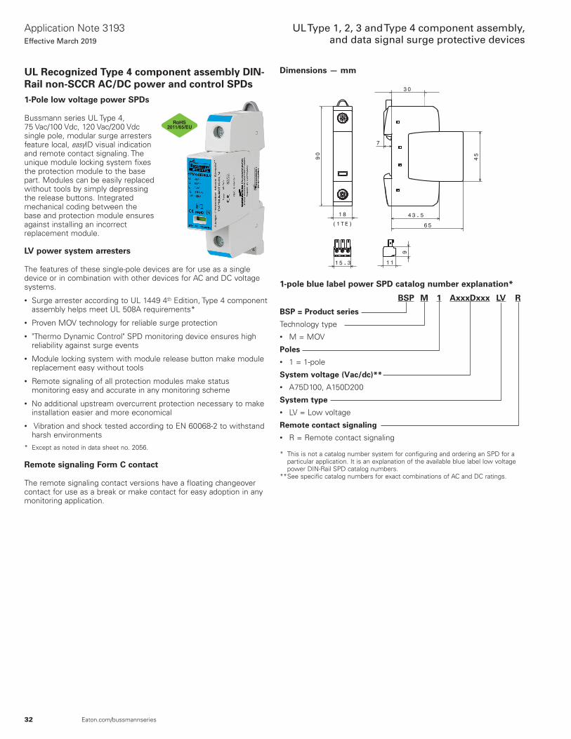
32
Application Note 3193Effective March 2019
UL Type 1, 2, 3 and Type 4 component assembly, and data signal surge protective devices
Eaton.com/bussmannseries
UL Recognized Type 4 component assembly DIN-Rail non-SCCR AC/DC power and control SPDs1-Pole low voltage power SPDs
Bussmann series UL Type 4, 75 Vac/100 Vdc, 120 Vac/200 Vdc single pole, modular surge arresters feature local, easyID visual indication and remote contact signaling. The unique module locking system fixes the protection module to the base part. Modules can be easily replaced without tools by simply depressing the release buttons. Integrated mechanical coding between the base and protection module ensures against installing an incorrect replacement module.
LV power system arresters
The features of these single-pole devices are for use as a single device or in combination with other devices for AC and DC voltage systems.
• Surge arrester according to UL 1449 4th Edition, Type 4 component assembly helps meet UL 508A requirements*
• Proven MOV technology for reliable surge protection
• "Thermo Dynamic Control" SPD monitoring device ensures high reliability against surge events
• Module locking system with module release button make module replacement easy without tools
• Remote signaling of all protection modules make status monitoring easy and accurate in any monitoring scheme
• No additional upstream overcurrent protection necessary to make installation easier and more economical
• Vibration and shock tested according to EN 60068-2 to withstand harsh environments
* Except as noted in data sheet no. 2056.
Remote signaling Form C contact
The remote signaling contact versions have a floating changeover contact for use as a break or make contact for easy adoption in any monitoring application.
Dimensions — mm
2011/65/EU
1-pole blue label power SPD catalog number explanation*
BSP M 1 AxxxDxxx LV R
BSP = Product series
Technology type• M = MOV
Poles• 1 = 1-pole
System voltage (Vac/dc)**• A75D100, A150D200
System type• LV = Low voltage
Remote contact signaling• R = Remote contact signaling
* This is not a catalog number system for configuring and ordering an SPD for a particular application. It is an explanation of the available blue label low voltage power DIN-Rail SPD catalog numbers.
** See specific catalog numbers for exact combinations of AC and DC ratings.

33
Application Note 3193Effective March 2019
UL Type 1, 2, 3 and Type 4 component assembly, and data signal surge protective devices
Eaton.com/bussmannseries
Catalog numbers and specifications
Ordering information — for 75 Vac/100 Vdc to 120 Vac/200 Vdc System volts/catalog no.System voltage 75 Vac/100 Vdc 120 Vac/200 Vdc
Catalog no. (base + modules) With remote signaling BSPM1A75D100LVR BSPM1A150D200LVRReplacement modules BPMA75D100LV BPMA150D200LVSpecificationsMax. continuous operating AC voltage [VC] 75 Vac 150 VacVoltage protection level [VPL] ≤0.4 kV ≤0.7 kVVoltage protection level at 5 kA [VPL] ≤0.35 kV ≤0.55 kVMax. continuous operating DC voltage [VC] 100 Vdc 200 VdcNominal discharge current (8/20 µs) [In] AC 10 kA 15 kANominal discharge current (8/20 µs) [In] DC 10 kA 12.5 kASurge current capacity(8/20 µs) [Imax] 40 kA 40 kATemporary overvoltage (TO V) 90 V / 5 sec. 175 V / 5 sec.Agency information* UL / cUL, CSA, KEMA UL / cUL, CSA, KEMA
Specifications — all catalog numbersSPD according to EN 61643-11 Type 2SPD according to IEC 61643-1 Class IIResponse time [tA] ≤25nsTOV characteristics WithstandOperating temperature range [TU] -40°C to +80°COperating state/fault indication Green (good) / red (replace)Number of ports 1Cross-sectional area (minimum) 14 AWG solid/strandedCross-sectional area (maximum) 1 AWG solid — 2 AWG strandedMounting 35 mm DIN-Rail per EN 60715Enclosure material Thermoplastic, UL 94 V0Location category IndoorDegree of protection IP20Capacity 1 module, DIN 43880
Warranty Five years**Remote contact signalingRemote contact signaling type Changeover contactAC switching capacity (volts/amps) 250 V/0.5 A
DC switching capacity (volts/amps) 250 V/0.1 A; 125 V/0.2 A; 75 V/0.5 AConductor ratings / cross-sectional area for remote contact signal ter-minals
60/75°C Max. 14 AWG solid/stranded
Ordering information Order from catalog numbers above
* Agency information not applicable to DC ratings.** See Limited Warranty Statement 3A1502 for details at Eaton.com/bussmannseries.

34
Application Note 3193Effective March 2019
UL Type 1, 2, 3 and Type 4 component assembly, and data signal surge protective devices
Eaton.com/bussmannseries
Dimensions — mm2-Pole low voltage control SPDs
Bussmann series UL Type 4 24 Vac/dc, 48 Vac/dc, 60 Vac/dc, 120 Vac/dc and 230 Vac/dc, two-pole, modular surge arresters feature local, easyID visual indication and remote contact signaling. The unique module locking system fixes the protection module to the base part. Modules can be easily replaced without tools by simply depressing the release buttons. Integrated mechanical coding between the base and protection module ensures against installing an incorrect replacement module.
LV system arresters
The features of these two-pole devices are for use in coordination with other upstream SPDs in UL 508A Applications*.
• Surge arrester according to UL 1449 4th Edition, Type 4 component assembly helps meet UL 508A requirements
• Proven MOV and GDT hybrid technology for reliable surge protection
• "Thermo Dynamic Control" SPD monitoring device ensures high reliability against surge events
• Module locking system with module release button make module replacement easy without tools
• Remote signaling on all protection modules make status monitoring easy and accurate in any monitoring scheme
• No additional upstream overcurrent protection needed so installation is easier and more economical
• Vibration and shock tested according to EN 60068-2 to withstand harsh environments
* UL 1449 4th Edition not applicable to DC voltages.
Remote signaling Form C contact
Remote signaling has a floating changeover contact for use as a break or make contact for easy application in any monitoring system.
2011/65/EU
2-pole blue label control SPD catalog number explanation*
BSP H 2 AxxxDxxx LV R
BSP = Product series
Technology type• H = Hybrid**
Poles• 2 = 2-pole
System voltage (Vac/dc)†• A24D24, A48D48, A150D150
System type• LV = Low voltage
Remote contact signaling• R = Remote contact signaling
* This is not a catalog number system for configuring and ordering an SPD for a particular application. It is an explanation of the available blue label low voltage control DIN-Rail SPD catalog numbers.
** Hybrid technology is a combination of one or more technologies in one module such as an MOV with a Gas Discharge Tube (GDT).
† See specific catalog numbers for exact combinations of AC and DC ratings.

35
Application Note 3193Effective March 2019
UL Type 1, 2, 3 and Type 4 component assembly, and data signal surge protective devices
Eaton.com/bussmannseries
Catalog numbers and specifications
Ordering information System volts/catalog no.System voltage 24 Vac/dc 48 Vac/dc 120 Vac/dcMax. continuous operating AC voltage (MCOV) [VC] 30 Vac/dc 60 Vac/dc 150 Vac/dcCatalog no.(base + modules) BSPH2A24D24LVR BSPH2A48D48LVR BSPH2A150D150LVRReplacement Modules BPHA24D24LV BPHA48D48LV BPHA150D150LVSpecificationsNominal AC voltage [Vo] 24 V 48 V 120 VMax. continuous operating AC voltage [VC] 30 V 60 V 150 VMax. continuous operating DC voltage [VC] 30 V 60 V 150 VNominal discharge current (8/20 µs) [In] 1 kA 1 kA 2 kATotal discharge current (8/20 µs) [L+N-Gnd] [Itotal] 2 kA 2 kA 4 kANominal load current AC [IL] 25 A 25 A 25 ACombined impulse [UOC] 2 kV 2 kV 4 kVCombined impulse [L+N-Gnd] [UOC total] 4 kV 4 kV 8 kVVoltage protection level [L-N] [VPL] ≤180 V ≤350 V ≤640 VVoltage protection level [L/N-Gnd] [VPL] ≤630 V ≤730 V ≤800 VSPD according to EN 61643-11 Type 3SPD according to IEC 61643-1 Class IIIResponse time [L-N] [tA] ≤25nsResponse time [L/N-Gnd] [tA] ≤100nsOperating temperature range [TU] -40°C to +80°COperating state/fault indication Green (good) / red (replace)Number of ports 1Cross-sectional area (min.) 18 AWG solid/strandedCross-sectional area (max.) 10 AWG solid/12 AWG strandedFor mounting on 35 mm DIN-Rail per EN 60715Enclosure material Thermoplastic, UL 94 V0Location category IndoorDegree of protection IP20Capacity 1 Module, DIN 43880Agency information* UL / cUL, CSA, KEMAProduct warranty Five years**Remote contact signalingRemote contact signaling type Changeover contactAC switching capacity (volts/amps) 250 V/0.5 ADC switching capacity (volts/amps) 250 V/0.1 A; 125 V/0.2 A; 75 V/0.5 AConductor ratings and cross-sectional area for remote contact signal terminals 60/75°C Max. 14 AWG solid/stranded
Ordering information Order from catalog numbers above
* Agency information not applicable to DC ratings.** See Limited Warranty Statement 3A1502 for details at Eaton.com/bussmannseries.

36
Application Note 3193Effective March 2019
UL Type 1, 2, 3 and Type 4 component assembly, and data signal surge protective devices
Eaton.com/bussmannseries
UL Listed data signal SPDs for telecom and instrumentation data signal applicationsOverview
• UL 497B Listed to protect equipment and wiring against the effects of excessive currents caused by lightning
• RJ45 / Ethernet data cable and universal 4 wire versions available for popular data signal applications
• DIN-Rail mount makes installation easy• Data signal SPDs complement BSPD, BSPA and SurgePOD PRO
Type 1, and DIN-Rail UL SCCR and non SCCR low voltage surge product lines for comprehensive system surge protection
• Five year warranty on all data signal SPDs
Universal 4 wire data signal SPDs for measurement, control and regulation circuits, and twisted pairs
Universal 4 wire, DIN-Rail mounted surge arresters provide effective protection with a minimum footprint and are designed for stringent requirements on the availability of measurement, control and regulation circuits, and bus systems.• Function-optimized design for safe use and easy
installation• Module removal without signal interruption via
“make-before-break” circuitry
RJ45 connector SPD for Ethernet data cables
The DIN-Rail mount BSPD48RJ45 SPD for Ethernet cable systems is easy to install between the patch panel and the active component in new, or retrofitting into existing installations. It is well suited for Gigabit Ethernet, ATM, ISDN, Voice over IP and Power over Ethernet (PoE).• CAT 6 according to ISO/IEC 11801 and in the
channel (Class E)• Power over Ethernet (PoE+ according to IEEE
802.3at) up to 57 volts
Specifications
ValueData signal SPD type
Universal 4 wire RJ45 EthernetTerminals/connectors Screws RJ45
System voltages 5 and 24 V 48 V
MCOV DC 6 and 33 V 48 VHousing material Polyamide PA 6.6 Die cast zincGrounding DIN-RailProtection IP20Operating temperature range -40°C to +80°CAgency information UL Listed 497BRoHS compliant Yes
DIN-Rail universal 4 wire SPDs
The Bussmann series universal four-pole, DIN-Rail mounted surge arrester is UL Listed 497B DIN-Rail mount universal surge protective device. It requires minimum space, while providing effective protection for the stringent requirements of measuring and control circuits, and bus systems.
To ensure safe operation, the arrester provides protection against vibration and shock up to a 30-fold acceleration of gravity. The device's function-optimized design allows quick and easy protection module removal via “make-before-break” terminals that assure data signal continuity in the protected and unprotected state.
For IEC Applications — Instruction for Surge Protective Device Use In Zone 2 Explosive Atmospheres per ATEX.
1. When installed in potentially explosive atmospheres, the Data Signal SPD shall be installed into an enclosure which meets the requirements of a recognized type of protection, in accordance with EN 60079-0.
2. The Data Signal DIN SPD as transient suppressor. This approval applies to the following equipment types:
• BSPD5DINLHF
• BSPD24DING
12.00
90.00
3.97
16.09
71.99
35.51
49.99 6.70
45.00
50.49
Ambient and temperature class
• -40°C to 80°C, T4: DEKRA 12ATEX0254 X: II 3 G Ex nA IIC T4 Gc
• Standards used for: ATEX: EN60079-0: 2009, EN 60079-15: 2005
Features
• UL 497B Listed
• Function-optimized design for safe use and easy installation
• Four-pole and base mounts on grounded 35 mm DIN-Rail
• Module removal without signal interruption via “make-before-break” circuitry
Dimensions — mm

37
Application Note 3193Effective March 2019
UL Type 1, 2, 3 and Type 4 component assembly, and data signal surge protective devices
Eaton.com/bussmannseries
Catalog numbers and specifications
Specification BSPD24DING BSPD5DINLHFNominal voltage (UN) 24 V 5 VNominal current at 45°C (IL) 0.75 A 1.0 AVPL line-line for Iimp D1 (Up) ≤102 V ≤25 VVPL line-PG for Iimp D1 (Up) ≤66 V ≤550 VVPL line-line at 1 kV/ µs C3 (Up) ≤90 V ≤11 VVPL line-PG at 1 kV/ µs C3 (Up) ≤45 V ≤550 VD1 Total lightning impulse current (10/350 µs) (Iimp) 10 kA 10 kAD1 Lightning impulse current (10/350 µs) per line (limp) 2.5 kA 2.5 kAC2 Total nominal discharge current (8/20 µs) (In) 20 kA 20 kAC2 Nominal discharge current (8/20 µs) per line (In) 10 kA 10 kASeries impedance per line 1.8 Ω 1.0 ΩMax. continuous operating DC voltage (UC) 33 V 6 VMax. continuous operating AC voltage (UC) 23.3 V 4.2 VCut-off frequency line-PG (fG) 6.8 MHz 100 MHzCapacitance line-line (C) ≤0.5 nF ≤25 pFCapacitance line-PG (C) ≤1.0 nF ≤16 pFATEX Approvals † †Agency information †† ††IEC 61643-21 test category D1, C2, C3Operating temperature range -40°C to +80°CDegree of protection IP20For mounting on 35 mm DIN-Rails per EN 60715Grounding Via base partColor / enclosure material Grey / Polyamide PA 6.6Test standards IEC 61643-21 / EN 61643-21, UL 497BConnection (input / output) Screw terminal
ConductorsSolid: 12-28 AWG (4-0.08 mm2)
Flexible: 14-28 AWG (2.5-0.08 mm2)Terminal torque 3.5 lb-in (0.4 N•m)Warranty 5 Years*
* See Bussmann series SPD Limited Warranty Statement (3A1502) for details at Eaton.com/bussmannseries.† DEKRA 12ATEX0254 X: II 3 G Ex nA IIC T4 Gc.†† ATEX, UL, CSA.
DIN-Rail universal 4 wire SPD applications
A universal 4 wire data signal SPD is specified by the bus system, measuring, control and communication technology.
The table below contains the technology in which the BSPD5DINLHF and BSPD24DING are suited to be used.
BSPD5DINLHF applicationsCAN-Bus (data line only) PROFIBUS DP/FMSC-Bus (Honeywell) PROFIBUS SIMATIC NETDevice Net (data line only) PSM EG RS422 and RS485FSK Rackbus (RS485)IEC-Bus (RS485) R BusInterbus INLINE, RS 485LON - TP/XF 78 RS422, V11MODBUS SafetyBUS pMPI Bus Securilan LON BusProcontic T200 (RS422) SUCONETBSPD24DING applications0-20mA, 4-20mA signals TTY 4-20mABinary signals

38
Application Note 3193Effective March 2019
UL Type 1, 2, 3 and Type 4 component assembly, and data signal surge protective devices
Eaton.com/bussmannseries
DIN-Rail RJ45/Ethernet cable SPD
The Bussmann series DIN-Rail mount BSPD48RJ45 Surge Protective Device (SPD) is a UL Listed 497B universal DIN-Rail mount surge protective device for RJ45/Ethernet cable systems. It is easy to install or retrofit Ethernet cable systems with RJ connectors.
The BSPD48RJ45 is installed between the patch panel and the active component (a switch for example). The snap-in mechanism of the supporting foot allows the SPD to be safely grounded via the DIN-Rail. For single applications, the BSPD48RJ45 comes with a supplied mounting bracket with cable lug.
Fulfilling the requirements of Category 6, the BSPD48RJ45 can be universally used for all data services up to nominal voltages of 48 V. It is well suited for existing services such as Gigabit Ethernet, ATM, ISDN, Voice over IP and Power over Ethernet (PoE+ acc. to IEEE 802.3at up to 57 V) and similar applications in structured cabling systems according to Class E up to 250 MHz. Protection of all pairs by means of powerful gas discharge tubes and one adapter filter matrix per pair.
• UL 497B Listed
• Easy to install or retrofit for protection of all lines
• CAT 6 according to ISO/IEC 11801
• CAT 6 in the channel (Class E)
• Power-over-Ethernet (PoE+ according to IEEE 802.3at)
DIN-Rail RJ45 SPD applications
BSPD48RJ45 applicationsBus systems, and measuring and control technologyIndustrial EthernetData networksATMEthernet 10/100/1000FDDI, CDDIIndustrial EthernetPower over Ethernet (PoE)Token RingVG any LANVideo systemsVideo (2 wire)
76.91
19.00 11.72
36.15
Catalog numbers and specifications
Specification BSPD48RJ45Nominal voltage (UN) 48 VMax. continuous operating DC voltage (UC) 48 VMax. continuous operating AC voltage (UC) 34 VMax. continuous DC voltage pair-pair (PoE) (UC) 57 VNominal current (IL) 1 AC2 Nominal discharge current (8/20 µs) line-line (In)
150 A
C2 Nominal discharge current (8/20 µs) line-PG (In)
2.5 kA
C2 Total nominal discharge current (8/20 µs) line-PG (In)
10 kA
C2 Nominal discharge current (8/20 µs) pair-pair (PoE) (In)
150 A
Voltage protection level line-line for In C2 (UP) ≤190 VVoltage protection level line-PG for In C2 (UP) ≤600 VVoltage protection level line-line for In C2 (PoE) (UP)
≤600 V
Voltage protection level line-line at 1 kV/ µs C3 (UP)
≤180 V
Voltage protection level line-PG at 1 kV/ µs C3 (UP)
≤500 V
Voltage protection level pair-pair at 1 kV/ µs C3 (PoE) (UP)
≤600 V
Insertion loss at 250 MHz ≤3 dBCapacitance line-line (C) ≤30pFCapacitance line-PG (C) ≤25pFOperating temperature range -40°C to +80°CDegree of protection IP10
Mounting 35 mm DIN-Rail per EN 60715
Connection (input / output) RJ45 socket / RJ45 socket
Pinning 1 / 2, 3 / 6, 4 / 5, 7 / 8
Grounding Via 35 mm DIN-Rail per EN 60715
Enclosure material Die cast zincColor Bare surface
Test standards IEC 61643-21 / EN 61643-21
Agency information UL 497BWarranty Five years*
* See Limited Warranty Statement 3A1502 for details at Eaton.com/bussmannseries.
Dimensions — mm

39
Application Note 3193Effective March 2019
UL Type 1, 2, 3 and Type 4 component assembly, and data signal surge protective devices
Eaton.com/bussmannseries
Frequently asked questions (FAQs)1. Why are surge protective devices needed?
Electronic devices and equipment often contain microprocessors that rely on fast digital ON/OFF coded sequence signals. Distortion on power or signal lines may disrupt these sensitive signals. As electronic equipment become smaller and more powerful, they become more sensitive to power and signal line distortions — particularly due their circuit density (microchips having literally thousands of transistors on a single chip). To help safeguard microprocessor reliability and uptime, surge protective devices have become the standard technology so that they don’t get “upset,” “degraded” or “damaged” by surge events, depending on the surge magnitude, the system configuration and load sensitivity.
2. What are surges, transients and temporary overvoltages (TOVs)?
All these are various forms of voltage disturbances and they are often used interchangeably. The true definition of these terms is related to their defined duration.
Transients as defined by IEEE Standard 1313.1-1996 are “a short-duration highly damped, oscillatory or non-oscillatory overvoltage, having duration of a few milliseconds or less. Transient overvoltage is classified as one of the following types: lightning, switching and very fast front, short duration.” These can be generated by voltage spikes which contain very little energy but are sufficient in voltage to cause damage to sensitive electronics.
Surge is an overvoltage condition that usually lasts longer in duration, >10 µs and <1 Ms and has higher energy to them that can cause damage to electrical and electronic equipment.
Temporary Overvoltage (TOV) are created by faults on the utility power distribution system and can cause extensive damage since their time domain is much longer (ms to seconds to hours).
3. What is a surge protector?
A surge protector is a device that limits transient overvoltages to a safe level, thus protecting equipment it is connected to from damage. A surge protector is generally referred to as an SPD (Surge Protective Device). There are different variations of SPDs such as lightning arresters and surge arresters or secondary surge arresters.
4. What is the difference between terms “Surge Arrester,” “Surge Protective Device (SPD)” and “Transient Voltage Surge Suppressor (TVSS)”?
These terms are often used interchangeably and rather loosely. However, the two terms have different meanings as determined by the National Electrical Code® (NEC) (www.nfpa.org), their UL listing, and applicable IEEE/ANSI standards.
According to NEC Article 285 TVSSs have been redefined as “Surge Protective Devices (SPDs) 1 kV or Less.” Previously titled “Transient Voltage Surge Suppressors: TVSSs,” this Article now uses the “type” designations that parallel the new requirements in UL 1449, 4th Edition. It also includes general, installation, and connection requirements for these SPD types installed on premises wiring systems rated 1 kV or less.
5. How does an SPD work?
A surge protector works by momentarily “switching” from a high impedance state into a highly conductive, low impedance state and shunting the surge energy to the ground and in doing so, limits the overvoltage to a lower, acceptable level. When the surge event is over, the protector returns to its high impedance state, ready for the next event or at end of life, fails open safely until replaced.
In other words, the SPD acts as a pressure relief valve. The pressure relief valve (SPD) does nothing until an overpressure (voltage surge) occurs in the supply (power) similar to the pressure relief valve.
6. What is shunting?
Shunting is the term used to describe the process by which an SPD redirects voltage transient energy to ground through a low impedance path.
7. How do I select and specify an SPD?
When it is determined an SPD is desired or required, specifying an SPD involves:
• Knowing the installation location and whether you can use Type 1, Type 2 or Type 3
• Determining the system type (single-phase, split-phase, Wye or Delta)
• Determining the system voltage
See page 5 for determining the location and suitable Type, and page 10 for specifying electrical system type and voltage.
Once all three are known, you can start the specification process by going to the appropriate product group:
• Type 1 UL Listed, NEMA 4X — SurgePOD PRO• Type 1 and Type 2 NEMA 1 and 4X — BSPD or BSPA• Open Type 1 UL Listed DIN-Rail — BSPMA black label high SCCR• Type 4 component assembly UL Recognized — Blue label low
voltage power (BSPMA) and control (BSPH)
8. Can anyone install an AC or DC SPD?
All SPDs, whether AC or DC, should be installed by qualified personnel following established safety procedures. This will help ensure that all the safety requirements and all local codes are met. The most common installation is in “parallel” to the load/device.
Surges & Transients
Time
Am
plitu
de
CurrentShunt
SPD CircuitLoad
6000V Voltage Surge
700V Residual (Let-Through) VoltageL
N/G

40
Application Note 3193Effective March 2019
UL Type 1, 2, 3 and Type 4 component assembly, and data signal surge protective devices
Eaton.com/bussmannseries
9. What are the differences between series vs. parallel SPDs?
Series installed SPD are typically used at the equipment level, either right in front of, or within the equipment they are protecting. These SPD have an “input” and an “output” whereas parallel SPD do not. A common example of a series connected SPD is a “surge strip.” Since they are connected in series with the equipment, they conduct load current. It is also common for a series AC SPD to contain a EMI/RFI noise filter. This filtering is useful when it is right in front of the equipment to filter out noise generated by other loads.
Parallel SPDs do not conduct load current and are commonly used where large surge energies exist. They’re used on service entrance panels and switchgear, plus branch and local panels. Parallel connected protectors are essential for all commercial and industrial AC applications.
10. What is a DIN-Rail SPD with replaceable modules?
Replaceable module SPDs contain one or more field removable/replaceable modules. The replaceable modules make maintenance easy and minimize downtime. The modules are the heart of the surge protector and usually contain the metal oxide varistors (MOV) and thermal disconnect. In some instances external fusing is required and or used in place of thermal disconnect.
11. What technologies are used in making an SPD?
Silicon Avalanche Diode (SAD) technology
The diode is installed reverse-biased under normal conditions. When the voltage rises above normal conditions the diode becomes forward-biased.
Not to scale
Advantages• Excellent voltage clamping• Sub-nanosecond response time• Repeatable• Low capacitance• Compact
Disadvantages• Limited impulse or current capability
Gas Discharge Tube (GDT)
The GDT may be regarded as a very fast acting switch having conducting properties that change very rapidly when breakdown occurs and transforms from an open-circuit to a quasi-short circuit. The result is an arc voltage of about 20 Vdc. There are four stages of operation before the tube fully switches.
SPD
CircuitLoad
SPD
CircuitLoad
TVSDTVSD
SchematicSymbol
Anode (+) Cathode (-)
+ V -
i
Breakdown Reverse Forward
VbrVd V
i
GDTGDT
SchematicSymbolReplaceable
modulesSPD system base

41
Application Note 3193Effective March 2019
UL Type 1, 2, 3 and Type 4 component assembly, and data signal surge protective devices
Eaton.com/bussmannseries
1. Non-operating domain: Characterized by practically infinite insulation resistance.
2. Glow domain: At the breakdown, the conductance increases suddenly. If the current that’s drained off by the gas discharge tube is less than about 0.5 A (rough value that differs from component to component), the glow voltage across the terminals will be in the 80-100 V range.
3. Arc regime: As the current increases, the gas discharge tube shifts from glow voltage to the arc voltage (20 V). It is this domain that the gas discharge tube is most effective because the current discharge can reach several thousand amps without the arc voltage across the terminals increasing.
4. Extinction: At a bias voltage roughly equal to the glow voltage, the gas discharge tube recovers to its initial insulating properties.
Advantages:• Handles very high impulse currents, makes it ideal for lightning
arresters• Low capacitance• Rugged and compact• Low conduction voltage• Repeatable
Disadvantages:• Slower, 2 to 3 µs response time• Extinguishing it is a challenge• Breakdown voltage depends on transient rise time allowing high
overshoot voltage
Metal Oxide Varistor (MOV):
An MOV is a variable resistor typically made of a large block of zinc oxide grains. They act like semiconductors, an insulator below the conduction voltage and a low value resistor above it. In conduction mode, the MOV diverts and dissipates the transient. MOVs generally connects in parallel to load. The thickness of the MOV determines the clamping voltage and Diameter determines the current capacity.
Breakdown Voltage
Glow Voltage
Arc Voltage
Operating ProfileCurrent
230V
60V
20V
Electrode 1
Electrode 2Arc
Gas Flow:- Radial- Axial
Gas-EvolvingInsulating Material
MOVSchematic
Symbol
MOV
Thickness Determines Clamping Voltage
DiameterDetermines SurgeCapacity
LeakageRegion
1000
Current (A)
Normal VaristorOperation
UpturnRegion
500
200
100
50
20
1010-8 10-6 10-4 10-2 100 102 104
Volta
ge (V
)
R =
109
Ω
R =
1-1
0Ω
Slope = 1α
I = kVα
Advantages:• Fast, sub micro-second response time• Good voltage conduction clamping, makes it ideal for surge
arresters• Handles high impulse currents• Rugged• Repeatable
Disadvantages:• Large relative size• High relative capacitance
12. What is a hybrid SPD?
A hybrid protector is a protector that uses more than one protection technology.

42
Application Note 3193Effective March 2019
UL Type 1, 2, 3 and Type 4 component assembly, and data signal surge protective devices
Eaton.com/bussmannseries
13. Where is the best place to install an SPD?
Ideally, an SPD should be installed at the main service entrance as close to the neutral-to-ground bond as possible, as shown below. This will ensure that surge energies are routed to earth by the most direct path. In larger facilities where distances between this primary protection and the equipment being protected are long, it is also good practice to use distributed protection all the way to point-of-use.
Standard for SPDs designed for repeated limiting of transient voltage surges as specified in the UL 1449 4th Edition for 50 or 60 Hz power circuits not exceeding 1000 V. Based upon the 1449 4th Edition standard, SPDs are either Listed or Recognized.
INTERNATIONAL STANDARD — IEC 61643-1
14. What is distributed (cascaded) surge protection?
Distributed protection, cascaded protection or coordination is the process of coordinating protection between the primary service entrance of a large facility and the internal branch distribution panels. Generally a surge protective device (SPD) with high surge handling capacity is installed at the service entrance while SPDs of lower surge ratings will be installed on the branch panels or dedicated supplies feeding sensitive equipment. This approach can be taken further to include point-of-use SPDs on long lines where they terminate to sensitive or critical equipment. A further example of such a distributed protection philosophy might include hard wired SPDs at the main and sub-panels and additional plug-in protectors on select equipment. (See pages 5 for SPD Types and installation locations.)
15. What standards govern SPDs?
NORTH AMERICA — ANSI / UL 1449 4th Edition
Class I Protecon Against Direct
Lightning Currents (Lightning Current Arrester)
(10/350 µs)
IEC 61643-1Performance Requirements of Surge Protecve Devices for Low-Voltage Power Supply Systems
Class IIIProtecon Against Switching
Overvoltages(Surge Arrester)
(1.2/50 µs; 8/20 µs)
Class IIProtecon Against Indirect
Lightning Effects(Surge Arrester)
(8/20 µs)
Low voltage surge protective devices – Part 1: Surge protective devices connected to 50/60 Hz AC and DC power circuits, and equipment rated up to 1000 Vrms, or 1500 Vdc. The IEC standard is a self certification or third party certification, such as KEMA, that will test and validate the results.
16. How is the North American surge suppression industry defined by safety standards and regulations?
NEC Requirements that SPDs follow:
• Changes to NEC 700.8 requires a listed SPD to be installed in or on all emergency system switchboards and panelboards.
• Installation of the SPD (Articles 280 and 285)
Institute of Electrical and Electronic Engineers (IEEE) Manages SPD:
• Surge environment C62.41.1• Characterization C62.41.2• Testing practices C62.45
National Electrical Manufacturers Association (NEMA) Standards that SPDs follow:
• Receptacles and plugs• Enclosures
Underwriters Laboratories (UL) Certifies to SPD Standards:
• Standard 1449 4th Edition – SPD standard• As required: Standard 1283 – EMI/RFI filters• NEMA ratings 1449 4th Edition current standard for SPDs
(10/350 µs)(1.2/50 µs; 8/20 µs)(8/20 µs)
Type 2Load side of the service
equipment device, including SPD located at the branch panel
(Surge Arrester)(8/20 µs)
Type 1 Secondary of the service
transformer and the line side of the service equipment over current device as well as the
load side(Surge Arrester)
(8/20 µs)
UL 1449 4th EditionPerformance Requirements of Surge Protective Devices
Type 3Point of Use SPD installed at a minimum conductor length of 10 meters from the electrical
service panel to POU
(Surge Arrester)(8/20 µs)

43
Application Note 3193Effective March 2019
UL Type 1, 2, 3 and Type 4 component assembly, and data signal surge protective devices
Eaton.com/bussmannseries
17. What is UL 1449?
UL 1449 is the safety standard for AC surge protective devices (SPD) used on systems with voltages of 600 Vac and less. This standard addresses SPDs that are installed on the loadside of the main disconnect. A UL 1449 Listed or Recognized surge protector has been thoroughly tested for safe operations. A Voltage Protection Rating (VPR) is assigned to a UL 1449 Listed SPD as a result of these tests to help users compare SPDs. UL 1449 4th Edition went into effect in September, 2009, making all previous 2nd Edition SPDs obsolete. Any older SPDs should be inspected and may be replaced to meet the new safety standard prescribed by NEC Articles 280 and 285, which call for SPD Type products certified to the UL 1449 4th Edition.
18. What is NEMA LS 1?
NEMA LS 1 was a surge protector performance standard. A surge protector which meets this standard is typically used in the most hostile surge environments, at the service entrance location. Other protector locations such as branch panel and local panel protection usually do not require such a formidable protector. NEMA LS 1 was rescinded in 2009 because the document was determined to be out of date and many industry standards related to the surge environment and surge suppression had been significantly updated since the original LS 1 standard was published in 1992.
19. I have a photovoltaic (PV) system with net metering; does it need a surge protection system?
Yes. For PV systems, DC surge protection should be installed where the DC voltage from the PV arrays terminates at the charge controller/inverter. AC protection should be installed at the inverter’s AC output to protect it from transients on the utility power lines. This can be caused by lightning or utility switching transients. In certain cases, protection should be located at the PV array locations, and at the array’s local DC control circuits — where applicable. See PV SPD data sheets and installation instructions for more application details. For details on PV SPDs and the entire line of SPD products from Bussmann, visit Eaton.com/bussmannseries.
20. Why is the lead (wire) length of an AC SPD so critical?
The shorter the lead length between the protector and your panel, the lower the let-through voltages will be to your equipment. This is crucial to the effectiveness of all parallel-connected surge protectors.
SPDs are typically connected in parallel with the load. This means that the protector does not carry load current. But more importantly, it means that the SPD must efficiently divert transient currents through it during an overvoltage event. The SPD must momentarily “look” like an electrical short-circuit in order to efficiently divert large amounts of current. The longer the wire, the more inductance it has, and the greater the (L x di/dt) factor will be. So when installing parallel surge protectors, keep the leads as close to, but not less than, six inches as possible for best performance.
21. What are the different designations for ratings between UL 1449 and IEC 61643-1?
The rating designations used in UL and IEC are in the table below.
Ratings Agency Designation
UL 1449 IEC 61643-1Nominal system voltage Vo Un
Surge current capacity 8x20 µs Imax Imax
Nominal discharge current 8x20 µs In In
Impulse Current 10x350 µs — Iimp
Voltage protection rating/level VPR Up
Maximum continuous operating voltage (MCOV) Vc Uc
Temporary overvoltage TOV Ut
22. How long does an SPD last?
How long an MOV-based SPD lasts depends upon how often it experiences a surge and for how long. Every time an MOV becomes conductive to shunt the surge to ground, its life is slightly degraded. The greater the surge, the greater the degradation of the MOV. One hit of 20 kA may degrade the MOVs life just as much as 15 hits at 0.2 kA. So, based upon the size and duration of surges an SPD encounters, it may last a day suppressing a large surge, or years suppressing smaller surges.
23. By VPR, what are the IEEE C62.41 defined withstand categories of equipment?
Category Description OvervoltageI Sensitive electronic circuits <1500 VII Domestic electrical equipment <2500 VIII Distribution panels, switchgear <4000 VIV Industrial equipment, meters <6000 V
24. Can a BSPD, BSPA and SurgePOD PRO insulated conductor be permanently identified for equipment grounding at each end using color tape?
No, the NEC only permits changing identification on 6 AWG and larger conductors. The BSPD, BSPA and SurgePOD PRO conductors are 10 AWG and too small. Details are contained in section 250.119 Identification of Equipment Grounding Conductors.
NEC 250.119 (A) contains these specific words: “An insulated or covered conductor larger than 6 AWG shall be permitted, at the time of installation, to be permanently identified as an equipment grounding conductor at each end and at every point where the conductor is accessible.”
25. Why are there requirements for installing some Type 1 or Type 2 SPDs not more than 10 feet from a bonded neutral-ground connection or greater than 10 feet from the bonded neutral-ground connection?
These requirements reflect a best practice for SPD wiring, as opposed to any code requirements. When an SPD is located within 10 feet (3 m) of the main service panel, the system can make use of the neutral line as an effective ground, due to the close proximity to the service entrance grounding conductor.
For distances greater than 10 feet (3 m), it is a best practice to select an SPD that has neutral-to-ground protection. This helps ensure a proper grounding is available for an SPD, which is critical to effectively protect the electrical system.
26. Where can I find the agency information for these SPDs?
To see the complete UL and CSA and other agency certificates go online to Eaton.com/bussmannseries. Then go to the web page of the desired product and click on the certificate links available.
27. Why should I install data signal SPDs in addition to power SPDs?
The need for surge suppression in general is driven by the increased use of sensitive electronic equipment that can be impaired or destroyed by surges on power circuits. And much of the electronic equipment used today is also connected via coaxial cable, twisted pair or Ethernet cables. Using data signal SPDs in addition to power SPDs helps assure the entire data or video system is protected from surges, regardless of the source.

44
Application Note 3193Effective March 2019
UL Type 1, 2, 3 and Type 4 component assembly, and data signal surge protective devices
Eaton.com/bussmannseries
Installing surge protective devices in accordance with NEC Article 240 and Feeder Tap Rule
Introduction
A common question heard by technical support is “What size fuse or breaker do I need when installing an SPD?” Discussed here is the need for installing an overcurrent protection device (OCPD) with a surge protective device (SPD), along with adhering to the applicable NFPA® 70 standards, National Electrical Code (NEC) rules, Authority Having Jurisdiction (AHJ), ANSI/UL 1449 ratings, and installation practices.
SPD design capabilities
Many SPDs employ thermally protected metal oxide varistors (MOV) that detect a transient high voltage surge and quickly shunt that surge to ground. Because the MOV cannot distinguish between transient and sustained overvoltage events, it must have a way to remove itself from the system during the overvoltage event. This keeps the SPD from entering into a thermal runaway situation that can cause internal and external damage.
The thermally protected MOVs have internal components that disconnect the MOV from the system during sustained overvoltage and overcurrent occurrences. This is accomplished by the MOV’s temperature rising to a critical value that initiates a mechanical separation from the SPD’s conducting components. Because the SPD itself is internally protected, it does not require external overcurrent protection in the form of a fuse or circuit breaker.
Other SPD types exist that don’t have component level protection on the MOVs or are built with a different components such as silicon avalanche diodes (SAD). SPDs that are built with these component components typically require external overcurrent protection because they can’t take themselves offline during an overcurrent event. If an OCPD is required for the SPD’s operation, this will be indicated in the device’s UL listing and manufacturers will clearly state this requirement in their installation instructions.
NEC Article 240.4 (overcurrent protection) protection of conductors
Whether the SPD requires an OCPD or not, the installation methods must meet all applicable electrical codes. NEC Article 240.4 states all conductors (other than flexible cords, flexible cables, and fixture wires) shall be protected with an OCPD in accordance with their ampacity specified in Article 301.15, unless otherwise permitted or required in Article 240.4(A) through (G). This applies to conductors extending beyond the switchboard, switchgear, or panelboard that are used to connect an SPD to the electrical system. Connecting an externally or side mounted SPD directly to a system bus where the conductors leave the enclosure must consider the requirements of NEC 240.21(B)(1). These requirements may require an adequately sized OCPD to be provided for protection of the SPD conductors. Acceptable OCPDs are listed fuses and circuit breakers.
NEC Article 310.15 (conductors for general wiring) ampacities for conductors rated 0—2000 V
Article 310.15(B)(16) defines the conductor ampacity that drives the maximum OCPD rating to be used to protect the conductors (OCPD rating is based on the conductor’s ampacity). E.g., 60°C 10 AWG conductors will require a 30 amp OCPD.
NEC Article 240.21 SPD installation using Feeder Tap Rule
Article 240.21(B)(1), (known as the 10 ft. Feeder Tap Rule), allows an SPD to be installed without overcurrent protection at the point of connection. The size of the conductors to the SPD are permitted to be sized based on the manufacturer instructions per the exception to NEC 240.21(B)(1)(1)(b). However, if the conductors to the SPD leave the enclosure, they must be protected by an OCPD not sized greater than the 10 times the ampacity of the conductors. For instance, if the conductor ampacity is 30 A, then an upstream OCPD of 300 A or less must be present.
Summary
When installing SPDs, NEC, local electrical codes and UL requirements must be followed. The proper OCPD must be used upon installation in order to meet the NEC requirements and maintain the SPD’s ANSI/UL 1449 Listing. In many instances, the reason the NEC dictates external overcurrent protection is to protect the conductors, not the SPD. SPDs containing an internal OCPD can be connected directly to the electrical bus only if the installation meets all requirements contained NEC Article 240.21(B)(1), the Feeder Tap Rule, the Authority Having Jurisdiction (AHJ), or by strictly following the manufacturer’s installations instructions on OCPD recommendations

45
Application Note 3193Effective March 2019
UL Type 1, 2, 3 and Type 4 component assembly, and data signal surge protective devices
Eaton.com/bussmannseries
ANSI/UL 1449 short-circuit current rating and NEC Article 285.6SPDs must comply with the current edition of ANSI/UL 1449 Standards for Safety Surge Protective Devices. The SPDs short-circuit current rating (SCCR) is determined as part of the ANSI/UL 1449 testing, and defines the SPD’s suitability for use on an AC power circuit that’s capable of delivering not more than a declared RMS symmetrical current during a short-circuit. This specification defines the maximum available fault current to which an SPD can be safely connected.
Article 285.7 requires that an SPD be marked with its SCCR and that it shall not be installed at a point on the system where the available fault current is greater than the SPD’s SCCR. E.g., an SPD marked 50 kA SCCR shall not be installed at a point in a system with 65 kA available fault current.
ANSI/UL 1449 testing with and without an OCPD
The NEC may require and externally mounted SPD to be protected by an OCPD if the feeder tap rule limitation is not met. Some manufacturers may choose using an OCPD to obtain their SDP’s SCCR or successfully pass the withstand test. For the SPDs requiring an OCPD, the installer must match the OCPD type and rating (fuses or breaker) that was used for their UL testing. E.g., if a fuse was used for UL testing, the same fuse type (fuse class), and voltage and amp ratings must be installed in the distribution equipment when installing an externally mounted SPD. Further, for the SPD to retain its UL Listing, the OCPD must be utilized in the installation.
Conversely, some manufacturers may not use an OCPD to obtain their UL 1449 Listing. When installing these units, UL 1449 may not require using an OCPD, but the NEC may require an OCPD if the feeder tap rule limitation is not met. Some installers assume and some manufacturers incorrectly promote that such externally mounted units can be connected directly to an electrical bus without overcurrent protection. This practice may be incorrect and violate the requirements of Article 240 of the NEC. The conductors of these units must be protected with an OCPD that is properly rated according to NEC Article 310.15 or meet the feeder tap rules of 240.21(B)(1). The fact that an SPD does not require a particular OCPD to pass the UL 1449 testing does not negate the need for overcurrent protection for installation.
SPDs containing an internal OCPD and the Feeder Tap Rule
There are SPDs that contain an internal OCPD such as a fuse or circuit breaker. A common misconception is that because the SPD’s OCPD is internally wired, an externally mounted unit can always be connected directly to the electrical bus without additional overcurrent protection. Failure to protect the conductors connecting the SPD to the system bus directly violates NEC and could lead to safety and liability concerns.
However, there are certain conditions or exceptions that allow installing an externally mounted SPD without an OCPD within the power distribution equipment at its connection point. These are outlined in NEC Article 240.21(B)(1) known as the 10 ft. Feeder Tap Rule.
In order to apply the Feeder Tap Rule to installing an SPD with an internal OCPD, all of the following conditions must be met:
1. The length of the tap conductors must not exceed 10 ft., e.g., the SPDs connecting leads cannot be greater than 10 ft.. (Rules also exist for taps that exceed 10 ft., but discussing them would be impractical for an SPD installation application.) For best performance, SPD connecting leads should be as short as possible (much less than 10 ft. whenever practical) and avoid sharp bends.
2. The tap conductors’ ampacity must not be less than the OCPD rating at the tap conductors’ termination, e.g., the SPD connecting lead ampacity cannot be less than the internal OCPD’s rating. At a minimum, 10 AWG conductors would be used to connect an SPD containing an internal 30 amp OCPD. Using 12 AWG conductors (ampacity = 20 A) would be a code violation and could not be used to connect an SPD containing an internal 30 amp OCPD.
However, a code exception permits tap conductors for specific listed devices, such as SPDs to be sized in accordance with the manufacturer’s instructions.
Exception to #2: “Where a Listed SPD is provided with specific instructions on minimum conductor sizing, the ampacity of the tap conductors supplying that SPD shall be permitted to be determined based on the manufacturer’s instructions.”
3. For field installations, if the tap conductors exit the enclosure where the tap is made, the OCPD rating on the tap conductor’s lineside must not exceed 10 times the tap conductor’s ampacity. For example, the upstream OCPD from where the SPD is tapped from cannot be rated at more than 10 times the SPD’s conductors’ ampacity. Therefore, if the conductor ampacity to the SPD is 30 A, then an upstream OCPD of 300 A or less must be present.
Summary
NEC and UL requirements must be followed when installing SPDs. The proper OCPD must be used in order to meet the NEC requirements and maintain the SPD’s ANSI/UL 1449 Listing.
If an external OCPD was not used during UL testing, the size and type will not be listed on the manufacturer’s product label. Under this condition, it’s the installer’s responsibility to ensure that the SPD’s conductors are protected with a suitable OCPD per the NEC and the local AHJ.
If the SPD was submitted for ANSI/UL 1449 testing with an external OCPD, the size and type required for installation will be listed in the manufacturer’s installation instructions and must be installed accordingly.
SPDs containing an internal OCPD can be connected directly to the electrical bus only if the installation meets all the requirements defined in NEC Article 240.12(B)(1), the Feeder Tap Rule, or by strictly following the manufacturer’s installations instructions and OCPD recommendations.

46
Application Note 3193Effective March 2019
UL Type 1, 2, 3 and Type 4 component assembly, and data signal surge protective devices
Eaton.com/bussmannseries
Type 4X — electrical enclosure rating
Type 4X Enclosures constructed for either indoor or outdoor use to provide a degree of protection to personnel against access to hazardous parts; to provide a degree of protection of the equipment inside the enclosure against ingress of solid foreign objects (windblown dust); to provide a degree of protection with respect to harmful effects on the equipment due to the ingress of water (rain, sleet, snow, splashing water, and hose directed water); that provides an additional level of protection against corrosion; and that will be undamaged by the external formation of ice on the enclosure.
SCCR (Isc)- Short-Circuit Current Rating
The suitability of an SPD for use on an AC power circuit that is capable of delivering not more than a declared rms symmetrical current at a declared voltage during a short-circuit condition.
SPD — Surge Protective Device
A surge protector is a device that limits transient overvoltages to a safe level, thus protecting equipment it is connected to from damage. A surge protector may also be expressed using the term SPD (Surge Protective Device).
There are different variations of SPD such as lightning arresters and surge arresters or secondary surge arresters.
Surge arrester
An SPD that has an In rating based on IEC 61643-1 or UL 1449 4th Edition. These products can be either DIN-Rail Style SPD in an assembly or NEMA Style SPDs (BSPD, BSPA and SurgePOD PRO). Typically in North American markets, surge arrestors are installed at the service entrance to handle large external surges, with additional surge arrestors (SPDs) installed throughout the electrical system down to individual equipment panels.
Surge current
Normal operation — current through MOV/SPD while conducting a surge – tends to be momentary.
Thermal disconnect
A means of disconnecting the SPD from the circuit upon reaching a predetermined temperature caused by conducting a surge to ground. This protects the MOV from going into a thermal runaway condition on commonly misapplied voltages or when an end-of-life condition is reached.
Thermal runaway
Operational condition when the sustained power dissipation of an SPD exceeds the thermal dissipation capability of the housing and connections, leading to a cumulative increase in the temperature of the internal elements culminating in failure.
TOV — Temporary Overvoltage
Temporary Overvoltages (TOVs) are created by faults on the utility power distribution system and can cause extensive damage since their time domain is much longer (ms to seconds to hours).
SPD GlossaryIEC Classes — per IEC 61643-1 Standard
Class I: Protection Against Direct Lightning Currents; based on 10/350 µs wave test (Lightning Current Arrester).
Class II: Protection Against Indirect Lightning Effects; based on 8/20 µs wave test (Surge Arrester).
Class III: Protection Against Switching Overvoltages; based on 1.2/50 µs; 8/20 µs wave test (Surge Arrester).
Iimp — impulse current rating (10/350 wave current impulse)
This rating is used for the classification of the SPD for test Class I Lightning Arresters per IEC 61643-1 Standard for surges with a virtual front time of 10 µs and a time to half-value of 350 µs. Defined by three parameters, a current peak value (Ipeak), a charge Q and a specific energy. Note: This is used for the classification of the SPD for test Class I SPDs under IEC 61643-1 Standard. UL DOES NOT have this rating.
Imax — surge current capacity
Crest value of a current through the SPD having an 8/20 µs wave shape and magnitude; Imax is the voltage and current development must not show any marks of disruptive obvious damage or aberration from the temperature stability; records of greater than In; arrester must safely discharge this current without an discharge or spark over. An SPD can withstand a single shot of surge current. In UL markets, this is a self certification rating.
In — nominal discharge current (8/20 wave current impulse)
This rating has a current impulse with a virtual front time of 8 µs and a time to half-value of 20 µs as defined by UL 1449 4th Edition and IEC 61643-1 Standards. Peak value of the current, selected by the manufacturer, through the SPD having a current wave shape of 8/20 µs where the SPD remains functional after 15 surges.
Lightning arrester
An SPD that has an Iimp rating based on IEC 61643-1 Standard. These products are typically DIN-Rail style SPDs.
MCOV/Vc/Uc — Maximum Continuous Operating Voltage
The maximum designated root mean-square (rms) value of the power frequency voltage that may be continuously applied to the mode of protection of an SPD. This is also the maximum voltage a system will see under the variance of normal operation and is the voltage at which an SPD starts to conduct and suppress a surge event.
MOV — Metal Oxide Varistor
MOV is a ceramic mass of zinc oxide grains, in a matrix of other metal oxides (such as small amounts of bismuth, cobalt, manganese) sandwiched between two metal plates (the electrodes).

47
Application Note 3193Effective March 2019
UL Type 1, 2, 3 and Type 4 component assembly, and data signal surge protective devices
Eaton.com/bussmannseries
UL SPD Types — Per 1449 4th Edition
Type 1 — One port, permanently connected SPDs, except for watt-hour meter socket enclosures, intended for installation between the secondary of the service transformer and the line side of the service equipment overcurrent device, as well as the load side, including watt-hour meter socket enclosures and Molded Case SPDs intended to be installed without an external overcurrent protective device. Type 1 SPDs for use in PV systems can be connected between the PV array and the main service disconnect.
DIN-Rail SPDs are open Type 1.
Type 2 — Permanently connected SPDs intended for installation on the load side of the service equipment overcurrent device; including SPDs located at the branch panel and Molded Case SPDs.
Type 3 — Point of utilization SPDs, installed at a minimum conductor length of 10 meters (30 feet) from the electrical service panel to the point of utilization, for example cord connected, direct plug-in, receptacle type and SPDs installed at the utilization equipment being protected. See marking in 80.3. The distance (10 meters) is exclusive of conductors provided with or used to attach SPDs.
Note: Type 2 and 3 SPDs were previously known as TVSSs.
Type 4 Component Assemblies — Component assembly consisting of one or more Type 5 components together with a disconnect (integral or external) or a means of complying with the limited current tests in 44.4.
Type 1, 2, 3 Component Assemblies — Consists of a Type 4 component assembly with internal or external short circuit protection.
Type 5 — Discrete component surge suppressors, such as MOVs that may be mounted on a PWB, connected by its leads or provided within an enclosure with mounting means and wiring terminations. Vo/Un — nominal system voltage
A nominal value assigned to designate a system of a given voltage class in accordance with ANSI C84.1. Typical voltages include 120, 208, 240, 277, 347, 480, 600 Vac.
VPR — Voltage Protection Rating
A rating selected from a list of preferred values as given in Table 63.1 of UL 1449 4th Edition and assigned to each mode of protection. The value of VPR is determined as the nearest highest value taken from Table 63.1 to the measured limiting voltage determined during the surge test using the combination wave generator at a setting of 6 kV, 3 kA. It is also known as “let-through voltage.”

Application Note 3193Effective March 2019
UL Type 1, 2, 3 and Type 4 component assembly, and data signal surge protective devices
Eaton, Bussmann, SurgePOD PRO and easyID are valuable trademarks of Eaton in the US and other countries. You are not permitted to use the Eaton trademarks without prior written consent of Eaton.
NEC is a registered trademark of the National Fire Protection Association, Inc.NFPA is a registered trademark of the National Fire Protection Association, Inc.UL is a registered trademark of the Underwriters Laboratories, Inc.
Eaton1000 Eaton BoulevardCleveland, OH 44122Eaton.com
Bussmann Division114 Old State RoadEllisville, MO 63021United StatesEaton.com/bussmannseries
© 2019 EatonAll Rights ReservedPrinted in USAPublication No. 3193 - BU-MC19025March 2019
Follow us on social media to get the latest product and support information.
For Eaton’s Bussmann series product information, call 1-855-287-7626 or visit:Eaton.com/bussmannseries