Bushings kV - Gas-insulated bushing - ANSI STANDARDS PASSONI... · IEC STANDARDS 60137 - ANSI...
8
1 GRID PABS Air-to-SF 6 Bushings 72.5 - 800 kV BUSHINGS Customer Benefits • Bushings with longer lifetime and higher reliability • Explosion and fire-proof design • Non-aging internal insulation • Installation in any position • On line monitoring in service AIR-TO-SF 6 - Gas-insulated bushing IEC STANDARDS 60137 - ANSI STANDARDS PABS bushings are gas-insulated types that meet IEC 60137 , ANSI/IEEE or other National Standards. They are designed for connection, in any ambient conditions, of GIS, GIL or Dead Tank Circuit Breakers to overhead transmission lines. Standard rated current is 2000 A through 5000 A, according to the rated voltage; it is possible to realize bushings up to 8000 A. For non-standard ratings, consult Passoni & Villa. AN ALSTOM COMPANY According to the operating temperature, the gas used for filling is pure SF 6 or a mixture of SF 6 and N2. The bushing is designated as follows: PABS.420.1425.4000.X PABS Gas-insulated bushings, air-to-SF 6 application 420 Insulation class in kV 1425 BIL in kV 4000 Rated current in A Voltage and current ratings Standard rated voltage range, at 50/60Hz, is: • 72.5 kV to 800 kV for composite design • 72.5 kV to 500 kV for porcelain design
Transcript of Bushings kV - Gas-insulated bushing - ANSI STANDARDS PASSONI... · IEC STANDARDS 60137 - ANSI...

1
GRID
PABSAir-to-SF6 Bushings72.5 - 800 kV
BUSHINGS
Customer Benefi ts• Bushings with longer lifetime
and higher reliability• Explosion and fi re-proof
design• Non-aging internal insulation• Installation in any position• On line monitoring in service
AIR-TO-SF6 - Gas-insulated bushing IEC STANDARDS 60137 - ANSI STANDARDS
PABS bushings are gas-insulated types that meet IEC 60137, ANSI/IEEE or other National Standards. They are designed for connection, in any ambient conditions, of GIS, GIL or Dead Tank Circuit Breakers to overhead transmission lines.
Standard rated current is 2000 A through 5000 A, according to the rated voltage; it is possible to realize bushings up to 8000 A. For non-standard ratings, consult Passoni & Villa.
AN ALSTOM COMPANY
According to the operating temperature, the gas used for filling is pure SF6 or a mixture of SF6 and N2.
The bushing is designated as follows:PABS.420.1425.4000.X
PABS Gas-insulated bushings, air-to-SF6 application
420 Insulation class in kV
1425 BIL in kV
4000 Rated current in A
Voltage and current ratings
Standard rated voltage range, at 50/60Hz, is:
• 72.5 kV to 800 kV for composite design
• 72.5 kV to 500 kV for porcelain design

22
AIR-TO-SF6 BUSHINGS PABS
Main FeaturesPABS: IEC and ANSI Standards gas-insulated bushings
Range 72.5 to 800 kV
High continuous withstand current up to 8000 A
High short-circuit current up to 100 kA - 1s; 63kA-3s
Gas-insulated bushings with pure SF6 or SF6-N2 mixture
Non-aging internal insulation
Air side: porcelain or composite insulator
Standard design as common gas zone with GIS/GIL
Explosion and fire-proof design
High quality sealing system and efficient gas leakage control: gas leakage less than 0.5% per year (usual ≤ 0.1%)
Installation in any position
In-service monitoring of main gas insulation throught density (pressure) control
Polyester-varnished aluminum flanges
1. HV Terminal2. Top closing plate3. Inner conductor4. Porcelain/composite insulator5. SF6 gas zone6. Internal shield7. Flange8. Transport cover
1
2
3
4
5
6
8
7
Fig. 1: Section
33
AIR-TO-SF6 BUSHINGS PABS
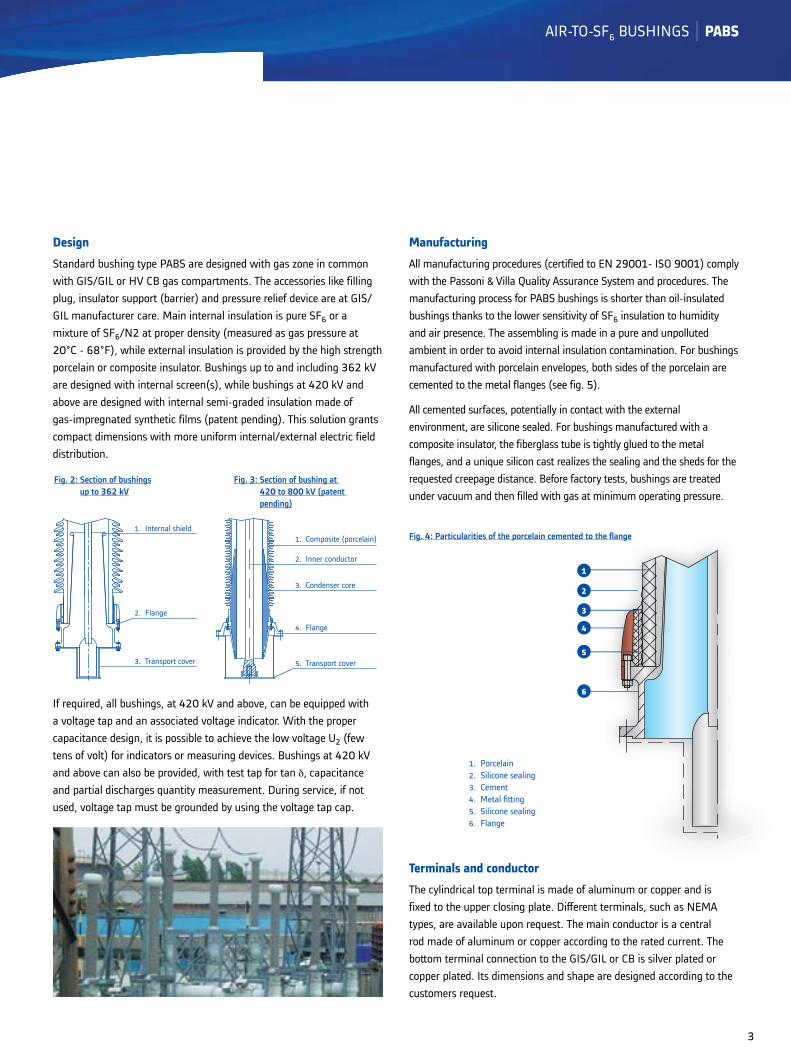
Design
Standard bushing type PABS are designed with gas zone in common with GIS/GIL or HV CB gas compartments. The accessories like filling plug, insulator support (barrier) and pressure relief device are at GIS/GIL manufacturer care. Main internal insulation is pure SF6 or a mixture of SF6/N2 at proper density (measured as gas pressure at 20°C - 68°F), while external insulation is provided by the high strength porcelain or composite insulator. Bushings up to and including 362 kV are designed with internal screen(s), while bushings at 420 kV and above are designed with internal semi-graded insulation made of gas-impregnated synthetic films (patent pending). This solution grants compact dimensions with more uniform internal/external electric field distribution.
If required, all bushings, at 420 kV and above, can be equipped with a voltage tap and an associated voltage indicator. With the proper capacitance design, it is possible to achieve the low voltage U2 (few tens of volt) for indicators or measuring devices. Bushings at 420 kV and above can also be provided, with test tap for tan δ, capacitance and partial discharges quantity measurement. During service, if not used, voltage tap must be grounded by using the voltage tap cap.
Manufacturing
All manufacturing procedures (certified to EN 29001- ISO 9001) comply with the Passoni & Villa Quality Assurance System and procedures. The manufacturing process for PABS bushings is shorter than oil-insulated bushings thanks to the lower sensitivity of SF6 insulation to humidity and air presence. The assembling is made in a pure and unpolluted ambient in order to avoid internal insulation contamination. For bushings manufactured with porcelain envelopes, both sides of the porcelain are cemented to the metal flanges (see fig. 5).
All cemented surfaces, potentially in contact with the external environment, are silicone sealed. For bushings manufactured with a composite insulator, the fiberglass tube is tightly glued to the metal flanges, and a unique silicon cast realizes the sealing and the sheds for the requested creepage distance. Before factory tests, bushings are treated under vacuum and then filled with gas at minimum operating pressure.
Terminals and conductor
The cylindrical top terminal is made of aluminum or copper and is fixed to the upper closing plate. Different terminals, such as NEMA types, are available upon request. The main conductor is a central rod made of aluminum or copper according to the rated current. The bottom terminal connection to the GIS/GIL or CB is silver plated or copper plated. Its dimensions and shape are designed according to the customers request.
Fig. 2: Section of bushingsup to 362 kV
Fig. 3: Section of bushing at 420 to 800 kV (patent pending)
1. Internal shield
2. Flange
3. Transport cover
1. Composite (porcelain)
2. Inner conductor
3. Condenser core
4. Flange
5. Transport cover
1
2
3
4
5
6
1. Porcelain2. Silicone sealing3. Cement4. Metal fi tting5. Silicone sealing6. Flange
Fig. 4: Particularities of the porcelain cemented to the fl ange

44
AIR-TO-SF6 BUSHINGS PABS
Air side
The external insulator is made of brown porcelain, (grey upon request) with cemented flanges, or composite insulator (resin fiberglass envelope covered by silicone sheds) glued to the metal parts. This system offers high mechanical strength during normal and above-normal service conditions. The alternating shed configuration (short-long sheds) is the most effective solution and has been proven by salt spray tests. The shed profile complies with the new IEC 60815 recommendations.
Composite insulators are recommended for all Bushings from 245 kV through 800 kV, as it significantly improves bushing reliability throughout its lifetime. Other benefits include:
• better behavior against weather elements, such as pollution and rain, due to the hydrophobic property of silicon rubber
• high mechanical withstand in case of impact, shocks and/or vibrations during handling, transportation or in service, such as for seismic activity
• higher safety for personnel and equipment in case of an internal fault (explosion-proof design).
Flange
Dimensions, flange type and lower conductor terminals, are designed in order to match the dimensions of the GIS/GIL or CB conductor. For Dead-Tank Circuit Breaker installation, thoroidal cores for measurement and protection, according to ANSI/IEEE, IEC or other National Standards, are supplied on request.
Insulation
The basic insulation is Sulphur-hexafluoride (SF6), which is not poisonous no flammable and has good dielectric, arc-exstinguishing and thermal capabilities. These characteristics enables it to be widely used in MV and HV equipments. The insulation characteristic of SF6 depends on the internal apparatus density and can be expressed in bar (PSI) at a temperature of 20 °C (68 °F). At approx. 3 bar (43.5 PSI) SF6 gas has the same dielectric strength as oil and several times higher than air.
The main SF6 insulating features are:
• non aging
• compressibility
• less sensitivity to humidity and air
• possibility of controlling the dielectric strength through the control of SF6 gas density (pressure).
Thanks to these characteristics, Air-to-SF6 bushings have a long life and a very high service reliability. In case of very low ambient temperatures (down to -40 °C/-40 °F) a mixture of SF6 and N2 is used.
Gaskets
The sealing system is of fundamental importance for any pressurized equipment. Specifically, it has to guarantee leakage of less than 0.5 % per year. For this purpose Passoni & Villa has a very severe regulation and tolerances concerning the choice, control and tests of gaskets and their grooves (i.e. material, resistence to high temperatures, ozone, radiation and other ambient contaminants that may influence the aging process of the gaskets). Our internal standards permit the leakage less than 0.1 % per year. O-ring type gaskets are made of EPDM which grants the usage in a wide range of temperatures: from -45 °C to +150 °C. With our double-gasket system, flange and grooves are lubricated with a special grease in order to guarantee the highest tightness and to prevent corrosive influences in severe ambient conditions.
Fig. 5: Flange fi xing holes (based on customer requirements)
Fig. 6: SF6 atomic model
n° holes øF
ANTICORROSIVEPROTECTION
O-RING GASKET
PABS
CUST
OM
ERSI
DE

55
AIR-TO-SF6 BUSHINGS PABS
Metal surface treatment
Upon request, according to specific customer requirements, finishing or final painting can be provided.
Tests
Type and routine tests are performed according to the latest edition of IEC 60137 or ANSI/IEEE Standards or other specific requirements. Important leakage tests assure service reliability. By measuring total leakage using a highly sensivity leak-meter (“Qm” method in accordance with IEC 68-2-17/94) we guarantee a leakage of less than 0.5 % per year, but normally it is less than 0.1 %.
In addition to routine and type tests prescribed by Standards, bushings from 420 kV through 800 kV are subjected to the Very Fast Transient (VFT) withstand tests.
In order to verify the bushing electrical withstanf capability the bushing with semi-graded internal insulation is tested with lightning impulses chopped in SF6, this simulating possible flashovers in GIS during its on-site tests according to IEC 62271-102 standard.
The repetition of type tests is performed in order to guarantee that the bushing has preserved all its characteristics after VFT tests.
Packing - Transportation
All bushings are protected with a plastic envelope and are horizontally transported in wooden cases. Bushings up to and including 170 kV are usually shipped in crates containing three pieces, while crates containing a single piece are used for higher voltages.
During transportation, the lower part of the bushing is closed and protected by a transport cover which is used also for fixing the central conductor. Bushings at 420 kV and above are transported with a relatively small overpressure of dry nitrogen (0,2-0,3 bar). The gas zone is filled through the automatic non-return valve.
Gas fi lling and refi lling
After the bushing is connected to the network and before energizing, it has to be vacuum treated together with the GIS/GIL or CB and then filled with gas. For filling, use pure SF6 gas or a mixture of SF6 and N2 according to the prescription of the Standards (IEC 60378 or other National Standard).
1
2
3
41. Porcelain/composite2. Toroidal3. Flange4. H.V.C.B.
Fig. 7: Toroidal core fi tted on the fl ange of the bushing
66
AIR-TO-SF6 BUSHINGS PABS
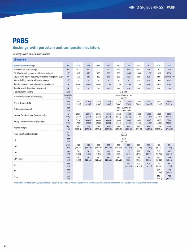
PABSBushings with porcelain and composite insulators
Dimensions
Nominal System Voltage KV 72.5 100 123 145 170 245 300 362 420 550
Rated line-to-earth voltage KV 42 58 72 84 98 141 173 209 242 318
BIL (Dry lightning impulse withstand voltage) KV 325 550 550 650 750 1050 1050 1175 1425 1550
Dry and wet power frequency withstand voltage (for 60s) KV 140 230 230 275 325 460 460 520 650 675/710/740
Wet switching impulse withstand voltage KV - - - - - - 850 950 1050 1175
Rated continuous current (standard value) up to A 2000 2000 2000 3150 3150 3150 3150 4000 4000 4000
Rated thermal short-time current (1s) KA 50 50 50 80 80 80 80 100 100 100
Rated dynamic current kAp 2.5 x Ith
Minimum operating pressure (abs.) bar/MPa(PSI)
4.0-6.5/0.04-0.065(60-95)
Arcing distance (L12)mm(in)
600(23.6)
1260(49.6)
1260(49.6)
1260(49.6)
1260(49.6)
1980(78.0)
2200(86.6)
2750(108.3)
3300(129.9)
3830(150.8)
C (Creepage distance) mm(in)
Min. 25 mm/kVMin. 0.984 in/kV
Normal Cantilever load (test) up to (1) N(lbf)
2000(450)
2000(450)
2500(562)
4000(900)
4000(900)
4000(900)
5000(1125)
5000(1125)
5000(1125)
5000(1125)
Heavy Cantilever load (test) up to (1) N(lbf)
3150(700)
4000(900)
4000(900)
4000(900)
5000(1125)
5000(1125)
5000(1125)
5000(1125)
5000(1125)
5000(1125)
Approx. weight kg(lb)
90(198.5)
115(253.5)
115(253.5)
115(253.5)
115(253.5)
310(683.4)
350(771.6)
650(1433.0)
1175(2590.4)
1250(2755.8)
Max. operating altitude (asl) m(ft)
1000(3281)
L4 mm(in)
130(5.12)
L10 mm(in)
288(11.34)
293(11.53)
293(11.53)
293(11.53)
293(11.53)
313(12.32)
305(12.01)
333(13.11)
90(3.54)
90(3.54)
L11 mm(in)
50(1.97)
50(1.97)
50(1.97)
60(2.36)
60(2.36)
37(1.45)
100(3.93)
100(3.93)
392(15.43)
392(15.43)
L14 (max.)mm(in)
240(9.45)
290(11.41)
290(11.41)
290(11.41)
290(11.41)
60(2.36)
60(2.36)
60(2.36)
309(12.16)
309(12.16)
D4 mm(in)
340(13.38)
420(16.53)
420(16.53)
60(2.36)
60(2.36)
D5 mm(in)
570(22.44)
570(22.44)
D14 mm(in)
750(29.52)
750(29.52)
Note: For non-listed ratings, please consult Passoni & Villa. D13 is variable according to the rated current. Flange dimensions (fi g. 6) are based to customer requirements.
Bushings with porcelain insulators
77
AIR-TO-SF6 BUSHINGS PABS
Dimensions
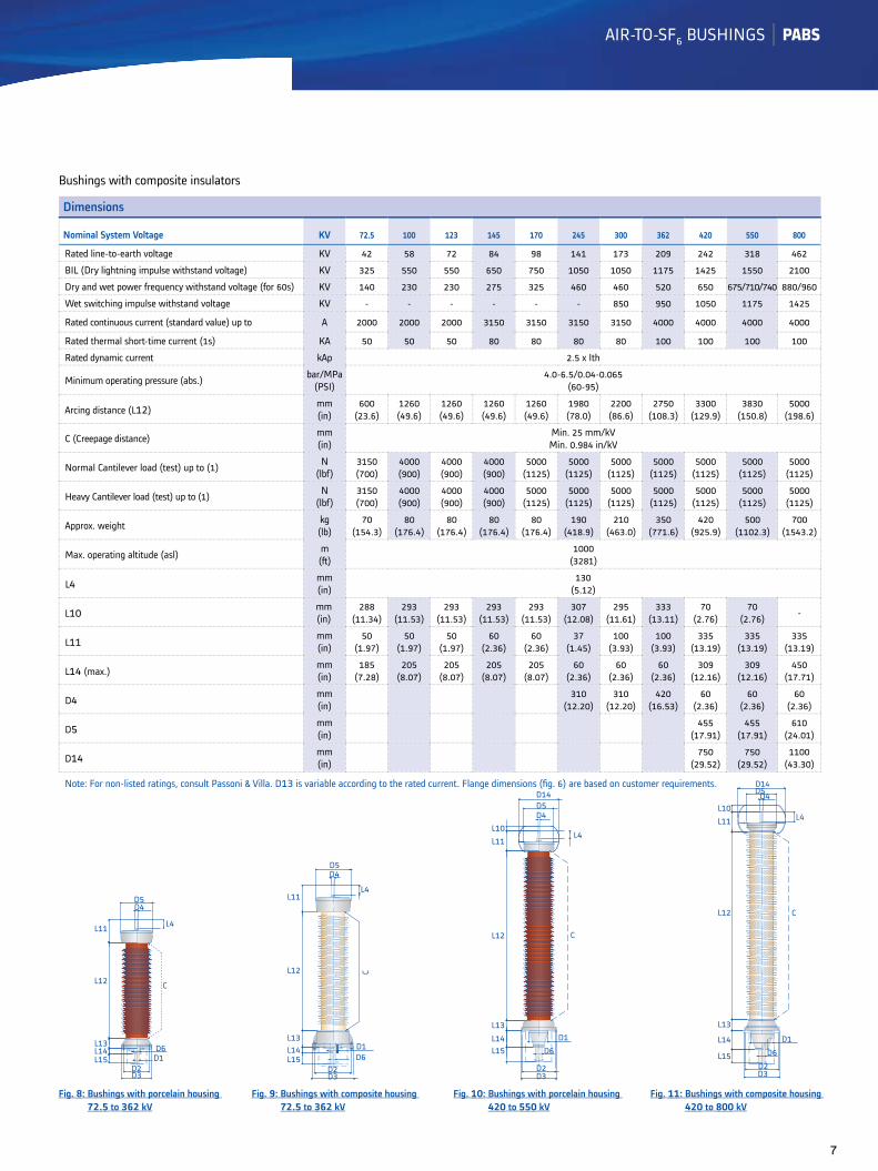
Nominal System Voltage KV 72.5 100 123 145 170 245 300 362 420 550 800
Rated line-to-earth voltage KV 42 58 72 84 98 141 173 209 242 318 462
BIL (Dry lightning impulse withstand voltage) KV 325 550 550 650 750 1050 1050 1175 1425 1550 2100
Dry and wet power frequency withstand voltage (for 60s) KV 140 230 230 275 325 460 460 520 650 675/710/740 880/960
Wet switching impulse withstand voltage KV - - - - - - 850 950 1050 1175 1425
Rated continuous current (standard value) up to A 2000 2000 2000 3150 3150 3150 3150 4000 4000 4000 4000
Rated thermal short-time current (1s) KA 50 50 50 80 80 80 80 100 100 100 100
Rated dynamic current kAp 2.5 x Ith
Minimum operating pressure (abs.) bar/MPa(PSI)
4.0-6.5/0.04-0.065(60-95)
Arcing distance (L12)mm(in)
600(23.6)
1260(49.6)
1260(49.6)
1260(49.6)
1260(49.6)
1980(78.0)
2200(86.6)
2750(108.3)
3300(129.9)
3830(150.8)
5000(198.6)
C (Creepage distance) mm(in)
Min. 25 mm/kVMin. 0.984 in/kV
Normal Cantilever load (test) up to (1) N(lbf)
3150(700)
4000(900)
4000(900)
4000(900)
5000(1125)
5000(1125)
5000(1125)
5000(1125)
5000(1125)
5000(1125)
5000(1125)
Heavy Cantilever load (test) up to (1) N(lbf)
3150(700)
4000(900)
4000(900)
4000(900)
5000(1125)
5000(1125)
5000(1125)
5000(1125)
5000(1125)
5000(1125)
5000(1125)
Approx. weight kg(lb)
70(154.3)
80(176.4)
80(176.4)
80(176.4)
80(176.4)
190(418.9)
210(463.0)
350(771.6)
420(925.9)
500(1102.3)
700(1543.2)
Max. operating altitude (asl) m(ft)
1000(3281)
L4 mm(in)
130(5.12)
L10 mm(in)
288(11.34)
293(11.53)
293(11.53)
293(11.53)
293(11.53)
307(12.08)
295(11.61)
333(13.11)
70(2.76)
70(2.76) -
L11 mm(in)
50(1.97)
50(1.97)
50(1.97)
60(2.36)
60(2.36)
37(1.45)
100(3.93)
100(3.93)
335(13.19)
335(13.19)
335(13.19)
L14 (max.)mm(in)
185(7.28)
205(8.07)
205(8.07)
205(8.07)
205(8.07)
60(2.36)
60(2.36)
60(2.36)
309(12.16)
309(12.16)
450(17.71)
D4 mm(in)
310(12.20)
310(12.20)
420(16.53)
60(2.36)
60(2.36)
60(2.36)
D5 mm(in)
455(17.91)
455(17.91)
610(24.01)
D14 mm(in)
750(29.52)
750(29.52)
1100(43.30)
Note: For non-listed ratings, consult Passoni & Villa. D13 is variable according to the rated current. Flange dimensions (fi g. 6) are based on customer requirements.
Bushings with composite insulators
Fig. 8: Bushings with porcelain housing 72.5 to 362 kV
Fig. 9: Bushings with composite housing 72.5 to 362 kV
Fig. 10: Bushings with porcelain housing 420 to 550 kV
Fig. 11: Bushings with composite housing 420 to 800 kV
D5D4
L4L11
L12 C
L13L14L15
D3D2
D1D6
D5D4
L11L4
L12 C
L13L14L15
D3D2
D6D1
D14D5D4
L10L11
L12
L13L14L15
D3D2
D6D1
C
L4
D3D2
L15
L14
L13
L12
L11L10
D14D5D4
L4
C
D6D1
88
AIR-TO-SF6 BUSHINGS PABS
Grid
-Pro
duct
s-L3
-PAB
S-71
788-
V2-E
N ©
- Al
stom
, the
Als
tom
logo
and
any
alte
rnat
ive
vers
ion
ther
eof a
re tr
adem
arks
and
ser
vice
mar
ks o
f Als
tom
. The
oth
er n
ames
men
tione
d, re
gist
ered
or n
ot, a
re th
e pr
oper
ty o
f the
ir re
spec
tive
com
pani
es. T
he te
chni
cal
and
othe
r dat
a co
ntai
ned
in th
is d
ocum
ent a
re p
rovi
ded
for i
nfor
mat
ion
only.
Nei
ther
Als
tom
, its
offi
cers
nor
em
ploy
ees
acce
pt re
spon
sibi
lity
for o
r sho
uld
be ta
ken
as m
akin
g an
y re
pres
enta
tion
or w
arra
nty
(whe
ther
exp
ress
or i
mpl
ied)
as
to th
e ac
cura
cy o
r co
mpl
eten
ess
of s
uch
data
or t
he a
chie
vem
ents
of a
ny p
roje
cted
per
form
ance
crit
eria
whe
re th
ese
are
indi
cate
d. N
o lia
bilit
y is
acc
epte
d fo
r any
relia
nce
plac
ed u
pon
the
info
rmat
ion
cont
aine
d in
this
bro
chur
e. A
lsto
m re
serv
es th
e rig
ht to
revi
se o
r cha
nge
thes
e da
ta a
t any
tim
e w
ithou
t fur
ther
not
ice.
Prin
ted
on p
aper
mad
e w
ith p
ure
ECF
(Ele
men
tal C
hlor
ine
Free
) eco
logi
cal c
ellu
lose
pro
duce
d fr
om tr
ees
grow
n in
pro
duct
ion
fore
sts
unde
r res
pons
ible
man
agem
ent,
and
sele
cted
recy
cled
thre
e-la
yer fi
bre
s.
Following the acquisition of PASSONI & VILLA, Alstom Grid now offers a large portfolio of condenser bushings for AC orDC operation. If you require any further information, please address your queries to
[email protected] AN ALSTOM COMPANY
GRID
Alstom Grid Worldwide Contact Centre www.grid.alstom.com/contactcentreTel.: +44 (0) 1785 250 070 www.grid.alstom.com
To contact the manufacturerViale Suzzani, 229 20162 MILANO (Italy)Tel.: +39 02 661 221Fax: +39 02 647 09 06Email: [email protected]
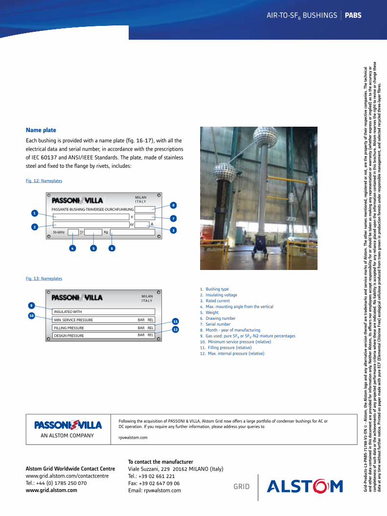
Name plate
Each bushing is provided with a name plate (fig. 16-17), with all the electrical data and serial number, in accordance with the prescriptions of IEC 60137 and ANSI/IEEE Standards. The plate, made of stainless steel and fixed to the flange by rivets, includes:
PASSANTE-BUSHING-TRAVERSEE-DURCHFUHRUNG
50-60Hz
A
MILANI TA LY
Kg
kV
1
23
4 5
7
6
8
N°
Fig. 12: Nameplates
MILANI TA LY
BAR REL
BAR REL
BAR REL
INSULATED WITH
MIN. SERVICE PRESSURE
FILLING PRESSURE
DESIGN PRESSURE
9
11
12
10
Fig. 13: Nameplates
1. Bushing type2. Insulating voltage3. Rated current 4. Max. mounting angle from the vertical5. Weight6. Drawing number 7. Serial number8. Month - year of manufacturing9. Gas used: pure SF6 or SF6-N2 mixture percentages10. Minimum service pressure (relative)11. Filling pressure (relative)12. Max. internal pressure (relative)