Bus node Valve terminal VTUB-12 Bus connection
41
Valve terminal VTUB-12
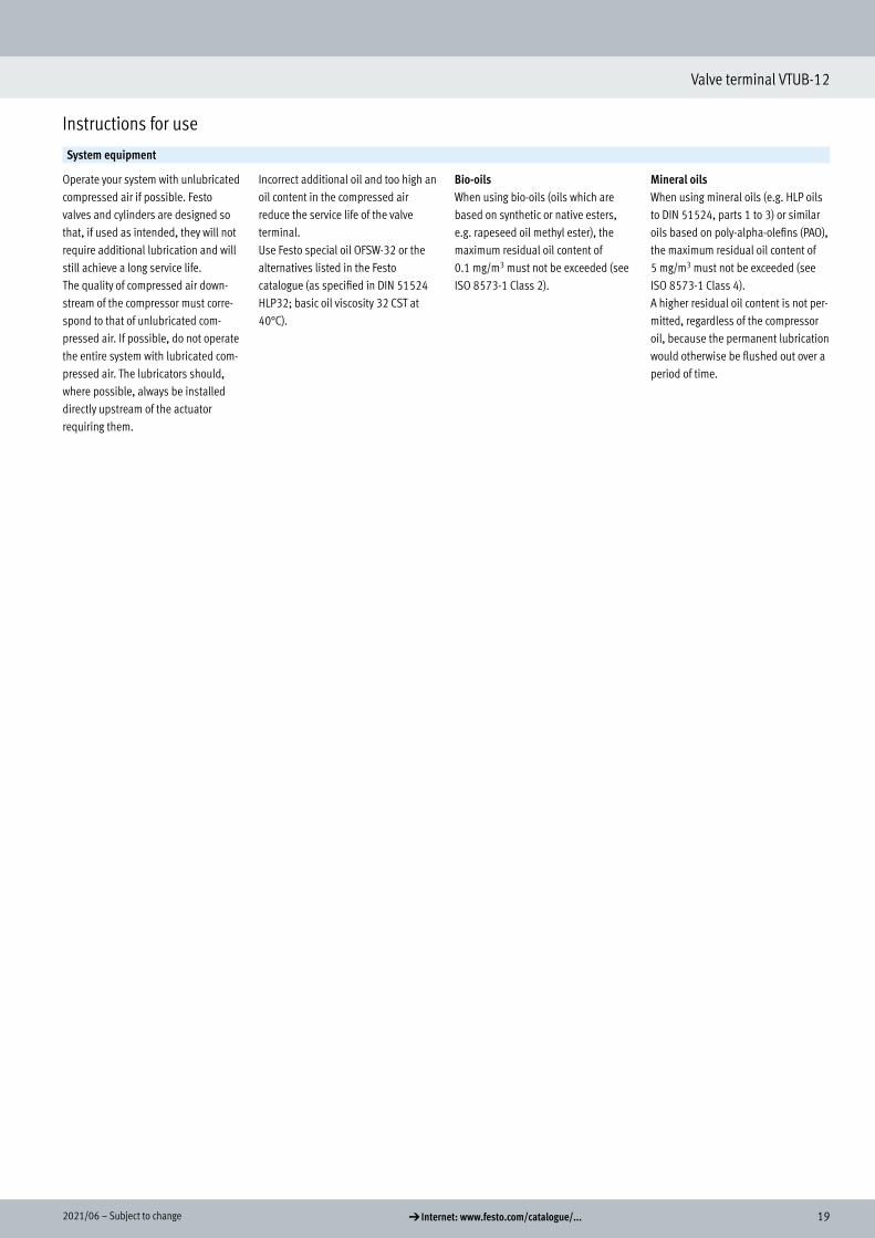
Transcript of Bus node Valve terminal VTUB-12 Bus connection

Bus node
Bus connection
Electrical connection block
H-rail mounting
Connecting cables
Plug socket
Inscription label
Valve terminal VTUB-12
2 d Internet: www.festo.com/catalogue/... Subject to change – 2021/06
Valve terminal VTUB-12
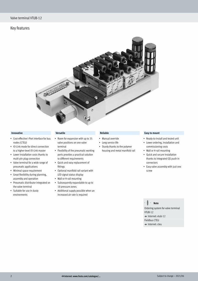
Key features
Innovative Versatile Reliable Easy to mount
• Cost-effective I-Port interface for bus nodes (CTEU)
• IO-Link mode for direct connection to a higher-level IO-Link master
• Lower installation costs thanks to multi-pin plug connection
• Valve terminal for a wide range of pneumatic applications
• Minimal space requirement• Great flexibility during planning,
assembly and operation• Pneumatic distributor integrated on
the valve terminal• Suitable for use in dusty
environments
• Room for expansion with up to 35 valve positions on one valve terminal
• Flexibility of the pneumatic working ports provides a practical solution to different requirements
• Quick and easy replacement of fittings
• Optional manifold rail variant with LED signal status display
• Wall or H-rail mounting• Subsequently expandable to up to
18 pressure zones• Additional supply possible when an
increased air rate is required
• Manual override• Long service life • Sturdy thanks to the polymer
housing and metal manifold rail
• Ready-to-install and tested unit• Lower ordering, installation and
commissioning costs• Wall or H-rail mounting• Quick and secure installation
thanks to integrated QS push-in connectors
• Easy valve assembly with just one screw
H- - Note
Ordering system for valve terminal VTUB-12a Internet: vtub-12Fieldbus CTEUa Internet: cteu
Key features

32021/06 – Subject to change d Internet: www.festo.com/catalogue/...
Valve terminal VTUB-12
Key features
3
4
1 2
6
5
[1] Safe operation: manual override non-detenting, non-detenting/detenting
[2] Valve replacement made easy Fast valve mounting with one screw on the manifold rail
[3] Choice of pneumatic outlets: QS push-in connectors, straight or angled
[4] Space-saving with up to 35 valve positions
[5] Simple electrical connections Multi-pin plug connection/I-Port interface
[6] Width 12 mm
Equipment optionsValve functions Electrical connection options
• 5/2-way valve, single solenoid• 5/2-way valve, double solenoid
• 3/2-way valve, closed• 3/2-way valve, open
Multi-pin plug• Sub-D 25-pin• Sub-D 44-pin• 2 ... 35 valve positions/
max. 35 solenoid coils
I-Port• Fieldbus interface (CTEU)• IO-Link mode• 3 ... 35 valve positions/
max. 35 solenoid coils
4 d Internet: www.festo.com/catalogue/... Subject to change – 2021/06
Valve terminals VTUB-12
Key features
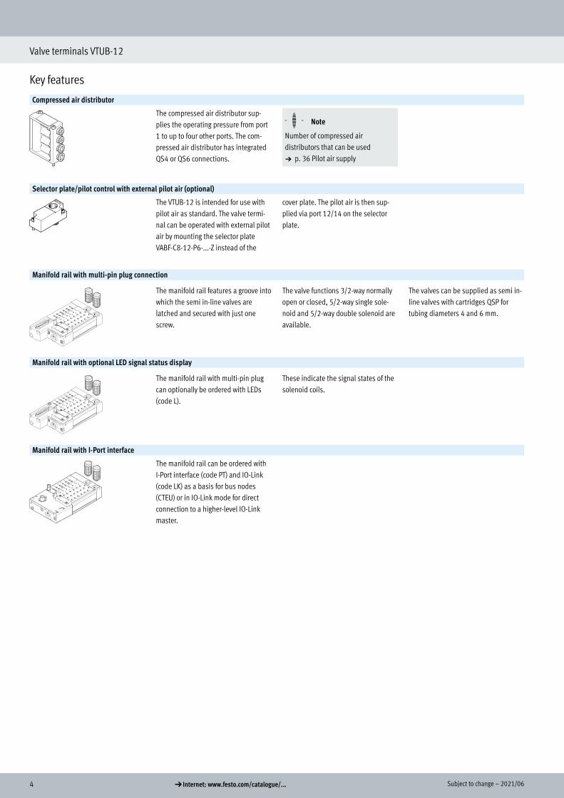
Compressed air distributor
The compressed air distributor sup-plies the operating pressure from port 1 to up to four other ports. The com-pressed air distributor has integrated QS4 or QS6 connections.
H- - Note
Number of compressed air distributors that can be useda p. 36 Pilot air supply
Selector plate/pilot control with external pilot air (optional)
The VTUB-12 is intended for use with pilot air as standard. The valve termi-nal can be operated with external pilot air by mounting the selector plate VABF-C8-12-P6-...-Z instead of the
cover plate. The pilot air is then sup-plied via port 12/14 on the selector plate.
Manifold rail with multi-pin plug connection
The manifold rail features a groove into which the semi in-line valves are latched and secured with just one screw.
The valve functions 3/2-way normally open or closed, 5/2-way single sole-noid and 5/2-way double solenoid are available.
The valves can be supplied as semi in-line valves with cartridges QSP for tubing diameters 4 and 6 mm.
Manifold rail with optional LED signal status display
The manifold rail with multi-pin plug can optionally be ordered with LEDs (code L).
These indicate the signal states of the solenoid coils.
Manifold rail with I-Port interface
The manifold rail can be ordered with I-Port interface (code PT) and IO-Link (code LK) as a basis for bus nodes (CTEU) or in IO-Link mode for direct connection to a higher-level IO-Link master.

52021/06 – Subject to change d Internet: www.festo.com/catalogue/...
Valve terminal VTUB-12
Key features
Sub-base for semi in-line valve
The valve VUVB-12 can be operated as an individual valve using an individual sub-base (single width for single sole-noid valves or
double width for double solenoid valves). The power is supplied via the connecting cable NEBV and KMYZ and the adapter (M8x1)
with corresponding connecting cable (a accessories, p. 36)
Cover plate
Plate without valve function for reserv-ing valve positions on a valve terminal.
Valve and cover plate are attached to the manifold rail using one screw.
Power supply module
The power supply module occupies one valve position and can be used as an additional supply or for supplying a pressure zone.
The power supply module is attached to the manifold rail using one screw.
Separator for duct separation
Pressure zone separation can be real-ised in duct 1 in the manifold rail. Up to 18 pressure zones can be created on the valve terminal in this way.
There must be at least 2 valve positions between 2 separators.

6 d Internet: www.festo.com/catalogue/... Subject to change – 2021/06
Valve terminals VTUB-12
Key features
Integration of the I-Port interface/IO-Link
Different bus nodes are used for integration in the control systems of various manufacturers.The following protocols are supported with the compatible bus node CTEU:
• CANopen• DeviceNet• EtherCAT• CC-Link• PROFIBUS DP
• AS-Interface• PROFINET• EtherNet/IP• VARAN
Use of the electrical connection block CAPC permits decentralised installa-tion of bus nodes CTEU on a further valve terminal or input modules with I-Port interfaces (a installation system CTEU/CTEL)
System overview, example
7
3
9
8
6
5
4
10
1
2
[1] Fieldbus[2] IO-Link/ I-Port[3] PLC[4] Bus node CTEU (I-Port master) on
electrical connection block CAPC[5] Valve terminal VTUB-12 with bus
node CTEU[6] CPX terminal with bus node and
CTEL master[7] Valve terminal CPV with I-Port
interface/IO-Link[8] Input module CTSL[9] Pneumatic drive with sensor[10] Pneumatic drive
• Communication with the higher-level controller via fieldbus
• Use a bus node CTEU compatible with the fieldbus protocol
• Up to 64 inputs/outputs (solenoid coils), depending on the valve terminal
72021/06 – Subject to change d Internet: www.festo.com/catalogue/...
Valve terminal VTUB-12
Peripherals overview
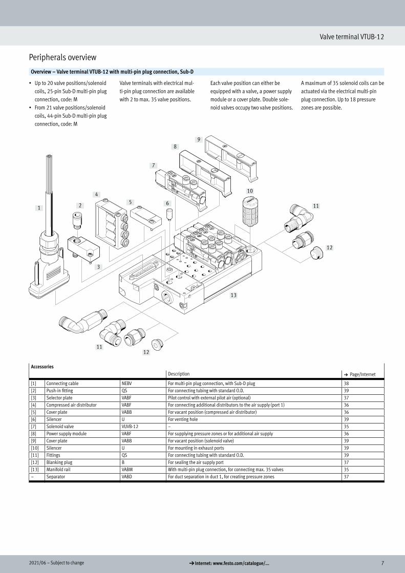
Overview – Valve terminal VTUB-12 with multi-pin plug connection, Sub-D
• Up to 20 valve positions/solenoid coils, 25-pin Sub-D multi-pin plug connection, code: M
• From 21 valve positions/solenoid coils, 44-pin Sub-D multi-pin plug connection, code: M
Valve terminals with electrical mul-ti-pin plug connection are available with 2 to max. 35 valve positions.
Each valve position can either be equipped with a valve, a power supply module or a cover plate. Double sole-noid valves occupy two valve positions.
A maximum of 35 solenoid coils can be actuated via the electrical multi-pin plug connection. Up to 18 pressure zones are possible.
1 2
12
11
10
98
7
654
3
11
13
12
AccessoriesDescription a Page/Internet
[1] Connecting cable NEBV For multi-pin plug connection, with Sub-D plug 38[2] Push-in fitting QS For connecting tubing with standard O.D. 39[3] Selector plate VABF Pilot control with external pilot air (optional) 37[4] Compressed air distributor VABF For connecting additional distributors to the air supply (port 1) 36[5] Cover plate VABB For vacant position (compressed air distributor) 36[6] Silencer U For venting hole 39[7] Solenoid valve VUVB-12 – 35[8] Power supply module VABF For supplying pressure zones or for additional air supply 36[9] Cover plate VABB For vacant position (solenoid valve) 39[10] Silencer U For mounting in exhaust ports 39[11] Fittings QS For connecting tubing with standard O.D. 39[12] Blanking plug B For sealing the air supply port 37[13] Manifold rail VABM With multi-pin plug connection, for connecting max. 35 valves 35– Separator VABD For duct separation in duct 1, for creating pressure zones 37
Peripherals overview
8 d Internet: www.festo.com/catalogue/... Subject to change – 2021/06
Valve terminals VTUB-12
Peripherals overview
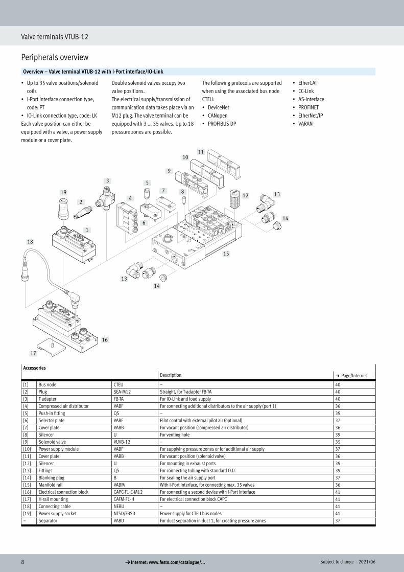
Overview – Valve terminal VTUB-12 with I-Port interface/IO-Link
• Up to 35 valve positions/solenoid coils
• I-Port interface connection type, code: PT
• IO-Link connection type, code: LKEach valve position can either be equipped with a valve, a power supply module or a cover plate.
Double solenoid valves occupy two valve positions. The electrical supply/transmission of communication data takes place via an M12 plug. The valve terminal can be equipped with 3 ... 35 valves. Up to 18 pressure zones are possible.
The following protocols are supported when using the associated bus node CTEU:• DeviceNet• CANopen• PROFIBUS DP
• EtherCAT• CC-Link• AS-Interface• PROFINET• EtherNet/IP• VARAN
17
18
19
2
3
4
5
6
7 8
9
1011
12 13
14
15
1413
16
1
AccessoriesDescription a Page/Internet
[1] Bus node CTEU – 40[2] Plug SEA-M12 Straight, for T-adapter FB-TA 40[3] T adapter FB-TA For IO-Link and load supply 40[4] Compressed air distributor VABF For connecting additional distributors to the air supply (port 1) 36[5] Push-in fitting QS – 39[6] Selector plate VABF Pilot control with external pilot air (optional) 37[7] Cover plate VABB For vacant position (compressed air distributor) 36[8] Silencer U For venting hole 39[9] Solenoid valve VUVB-12 – 35[10] Power supply module VABF For supplying pressure zones or for additional air supply 37[11] Cover plate VABB For vacant position (solenoid valve) 36[12] Silencer U For mounting in exhaust ports 39[13] Fittings QS For connecting tubing with standard O.D. 39[14] Blanking plug B For sealing the air supply port 37[15] Manifold rail VABM With I-Port interface, for connecting max. 35 valves 36[16] Electrical connection block CAPC-F1-E-M12 For connecting a second device with I-Port interface 41[17] H-rail mounting CAFM-F1-H For electrical connection block CAPC 41[18] Connecting cable NEBU – 41[19] Power supply socket NTSD/FBSD Power supply for CTEU bus nodes 41– Separator VABD For duct separation in duct 1, for creating pressure zones 37

92021/06 – Subject to change d Internet: www.festo.com/catalogue/...
Valve terminals VTUB-12
Peripherals overview
Sub-base for semi in-line valve
• Single design for single solenoid valves
• Double design for double solenoid valves
Electrical connection via connecting cable NEBV or KMYZ,
and adapter (M8x1) with correspond-ing connecting cable.
1
5
4
32
8
10
67 6
119
AccessoriesDescription a Page/Internet
[1] Solenoid valve, single solenoid VUVB-12 – 35[2] Double solenoid valve VUVB-12 – 35[3] Push-in fitting QS For port 2, 4: cartridge with push-in connector 39[4] Sub-base VABS Double design for individual double solenoid valve 36[5] Sub-base VABS Single design for individual single solenoid valve 36[6] Silencer AMTC For port 3, 5 (optional) 39[7] Push-in fitting QS For port 1: cartridge with push-in connector 39[8] Push-in fitting QS For port 12, 14: cartridge with push-in connector (optional) 39[9] Adapter VAVE M8x1 (optional), LED 40[10] Connecting cable NEBV, KMYZ Connecting cable (optional) 38[11] Inscription label holder IBS-6x10 – 37
10 d Internet: www.festo.com/catalogue/... Subject to change – 2021/06
Valve terminals VTUB-12
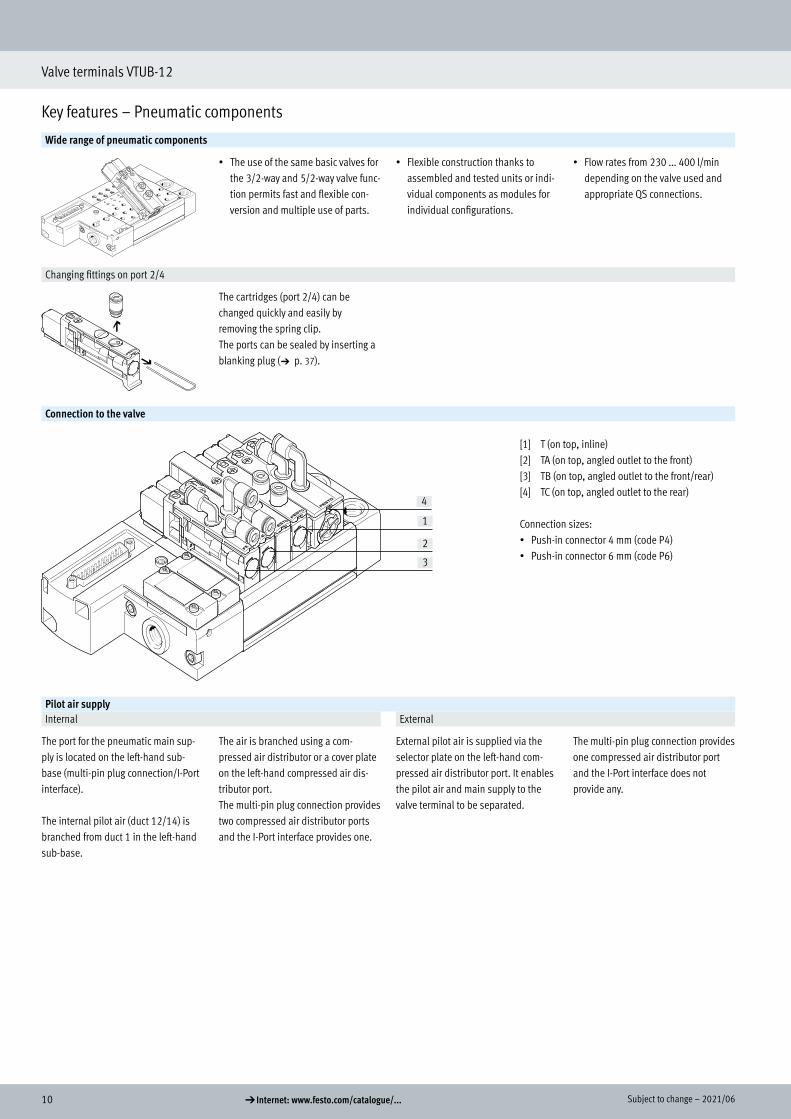
Key features – Pneumatic components
Wide range of pneumatic components
• The use of the same basic valves for the 3/2-way and 5/2-way valve func-tion permits fast and flexible con-version and multiple use of parts.
• Flexible construction thanks to assembled and tested units or indi-vidual components as modules for individual configurations.
• Flow rates from 230 ... 400 l/min depending on the valve used and appropriate QS connections.
Changing fittings on port 2/4
The cartridges (port 2/4) can be changed quickly and easily by removing the spring clip.The ports can be sealed by inserting a blanking plug (a p. 37).
Connection to the valve
4
3
2
1
[1] T (on top, inline)[2] TA (on top, angled outlet to the front)[3] TB (on top, angled outlet to the front/rear)[4] TC (on top, angled outlet to the rear)
Connection sizes:• Push-in connector 4 mm (code P4)• Push-in connector 6 mm (code P6)
Pilot air supplyInternal External
The port for the pneumatic main sup-ply is located on the left-hand sub-base (multi-pin plug connection/I-Port interface).
The internal pilot air (duct 12/14) is branched from duct 1 in the left-hand sub-base.
The air is branched using a com-pressed air distributor or a cover plate on the left-hand compressed air dis-tributor port.The multi-pin plug connection provides two compressed air distributor ports and the I-Port interface provides one.
External pilot air is supplied via the selector plate on the left-hand com-pressed air distributor port. It enables the pilot air and main supply to the valve terminal to be separated.
The multi-pin plug connection provides one compressed air distributor port and the I-Port interface does not provide any.
Key features – Pneumatic components

112021/06 – Subject to change d Internet: www.festo.com/catalogue/...
Valve terminals VTUB-12
Key features – Pneumatic components
Creating pressure zones
Up to 18 pressure zones can be creat-ed using the separator VABD–C8 ... if different working pressures are re-quired. The separators are inserted at the required location in duct 1 in the manifold rail and screwed into place.The following rules apply:
• Two pressure zones can be realised without an additional power supply module (VABF-C8 ... ) if there is a compressed air supply at both ends. Only one separator in duct 1 is required for this.
• A power supply module (VABF-C8...) is additionally required after the third pressure zone; this module occupies one valve position.
• There must be at least 2 valve positions between 2 separators
H- - Note
• Pressure zones can be freely configured with the VTUB-12.
• Duct separation does not result in any valve positions being lost; however, valve positions will be lost if an additional supply is required.
• If a valve terminal with duct sepa-ration is ordered via the configura-tor, the duct separation comes already labelled.
• Older manifold rails predating ap-prox. mid-2013 cannot be retrofit-ted for the purpose of creating pressure zones.
• Additional information on assembly a Assembly instructions for VABD-C8-P1-D2
Duct separation
Duct separation and creation of pressure zones• Remove the end plate• Insert an Allen key (size 4) from
above at the required position in duct 1 in the manifold rail as a stop.
• Using another Allen key, push sep-arator VABD-C8 ... into duct 1 at the appropriate position as far as the stop and then turn the Allen key to secure in place.
• Fit the end plate• Affix the enclosed symbol labels to
the duct separation
DesignValve replacement Extension
The valves are attached to the alumini-um manifold rail using one screw.This means that the valves can be easily replaced. Use of high-quality
polymer guarantees minimum weight and maximum performance.
Cover plates can be replaced by valves at a later date. The dimensions, mounting points and the pneumatic installation already carried out do not change.
Valve functionCode Circuit symbol Width Description
12 mm 24 mm
M h – 5/2-way valve, single solenoid• Mechanical spring return• Non-reversible• Not suitable for vacuum
J – h 5/2-way valve, double solenoid• Non-reversible• Not suitable for vacuum
N h – 3/2-way valve, single solenoid• Normally open• Mechanical spring return• Non-reversible• Not suitable for vacuum
K h – 3/2-way valve, single solenoid• Normally closed• Mechanical spring return• Non-reversible• Not suitable for vacuum
12 d Internet: www.festo.com/catalogue/... Subject to change – 2021/06
Valve terminals VTUB-12
Key features – Display and operation
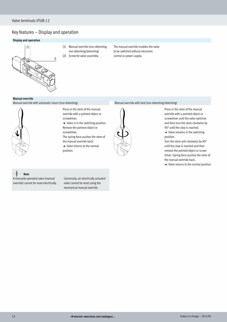
Display and operation
1
2
[1] Manual override (non-detenting, non-detenting/detenting)
[2] Screw for valve assembly
The manual override enables the valve to be switched without electronic control or power supply.
Manual overrideManual override with automatic return (non-detenting) Manual override with lock (non-detenting/detenting)
Press in the stem of the manual override with a pointed object or screwdriver.a Valve is in the switching position.Remove the pointed object or screwdriver.The spring force pushes the stem of the manual override back.a Valve returns to the normal position.
Press in the stem of the manual override with a pointed object or screwdriver until the valve switches and then turn the stem clockwise by 90° until the stop is reached.a Valve remains in the switching position.Turn the stem anti-clockwise by 90° until the stop is reached and then remove the pointed object or screw-driver. Spring force pushes the stem of the manual override back.a Valve returns to the normal position
H- - NoteA manually operated valve (manual override) cannot be reset electrically.
Conversely, an electrically actuated valve cannot be reset using the mechanical manual override.
Key features – Display and operation
132021/06 – Subject to change d Internet: www.festo.com/catalogue/...
Valve terminals VTUB-12
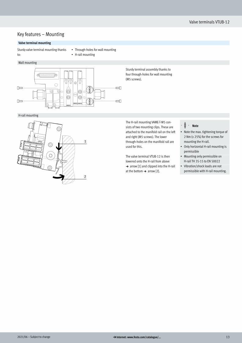
Key features – Mounting
Valve terminal mounting
Sturdy valve terminal mounting thanks to:
• Through-holes for wall mounting• H-rail mounting
Wall mounting
Sturdy terminal assembly thanks to four through-holes for wall mounting (M5 screws).
H-rail mounting
1
2
The H-rail mounting VAME-T-M5 con-sists of two mounting clips. These are attached to the manifold rail on the left and right (M5 screws). The lower through-holes on the manifold rail are used for this.
The valve terminal VTUB-12 is then lowered onto the H-rail from above a arrow [1] and clipped into the H-rail at the bottom a arrow [2].
H- - Note
• Note the max. tightening torque of 2 Nm (± 25%) for the screws for mounting the H-rail.
• Only horizontal H-rail mounting is permissible
• Mounting only permissible on H-rail TH 35-15 to EN 50022
• Vibration/shock loads are not permissible with H-rail mounting.
Key features – Mounting

14 d Internet: www.festo.com/catalogue/... Subject to change – 2021/06
Valve terminal VTUB-12
Key features – Electrical components
Multi-pin plug connection
Control signals from the controller to the valve terminal are transmitted via a pre-assembled multi-core cable, which substantially reduces installation time.
The valve terminal can be equipped with 2 ... 35 valves.
Versions• Sub-D connection
I-Port interface/IO-LinkIO-Link I-Port
IO-Link is an interface that supplies data for communication in addition to the power supply.An IO-Link system consists of an IO-Link master and IO-Link devices. The IO-Link master acts as the interface to the higher-level controller (PLC) and controls communication with the connected IO-Link devices.
One device with IO-Link (e.g. an IO-Link valve terminal from Festo) can be connected to each port on an IO-Link master.
The Festo-specific I-Port interface based on IO-Link offers the following connection options:• Directly to the fieldbus by mounting
a CTEU bus node• Connection to a higher-order I-Port
master from Festo
Overview
1
5
2
3
4
[1] Fieldbus[2] IO-Link[3] PLC[4] CTEU bus node
IO-Link master[5] Valve terminal VTUB-12 with
I-Port interface/IO-Link
Key features – Electrical components

152021/06 – Subject to change d Internet: www.festo.com/catalogue/...
Valve terminal VTUB-12
Key features – Electrical components
Protective circuitManifold rail with LED signal status display, multi-pin plug, 2-20 valve positions
H- - Note
The electrical protective circuit only relates to the optional LED variant with the multi-pin plug connection.
Manifold rail with LED signal status display, multi-pin plug, 21-35 valve positions
Electrical multi-pin plug connection
The following multi-pin plug connec-tions are available for the valve termi-nal VTUB-12:• Sub-D multi-pin plug connection
(25-pin)• Sub-D multi-pin plug connection
(44-pin)
Pins 1 ... 44 are used for addresses 0 ... 43 in order.
If fewer than 44 addresses are used for the valve terminal, the remaining pins are left free.Pins 22 ... 25 or 41 ... 44 are reserved for the neutral conductor or 24 V respectively.
The valves are switched using positive or negative logic (positive switching or negative switching). Mixed operation is not permitted.
Each pin on the multi-pin plug can ac-tuate exactly one solenoid coil. If the maximum configurable number of valve positions is 35, then 35 valves can be addressed with one solenoid coil (single solenoid).
H- - Note
A double solenoid valve occupies two valve positions.With 17 or more valve positions, the number of available valve positions for double solenoid valves decreases.

16 d Internet: www.festo.com/catalogue/... Subject to change – 2021/06
Valve terminals VTUB-12
Key features – Electrical components
Pin allocation – Sub-D plug, 25-pinPin Address/coil 15-wire, NEBV-S1...25-K-...-LE15 25-wire, NEBV-S1...25-K-...-LE25
Wire colour1) of connecting cable
1 0 WH WH2 1 BN BN3 2 GN GN4 3 YE YE5 4 GY GY6 5 PK PK7 6 BU BU8 7 RD RD9 8 BK BK10 9 VT VT11 10 GY PK GY PK12 11 RD BU RD BU13 12 – GN WH14 13 – BN GN15 14 – YE WH16 15 – BN YE17 16 – GY WH18 17 – BN GY19 18 – WH PK20 19 – BN PK
H- - Note
The drawing shows the view onto the pins of the Sub-D plug.
21 – – BU WH22 0 V/24 V – BN BU23 0 V/24 V GN WH RD WH24 0 V/24 V BN GN BN RD25 0 V/24 V YE WH BK WH
1) To IEC 757
172021/06 – Subject to change d Internet: www.festo.com/catalogue/...
Valve terminals VTUB-12
Key features – Electrical components
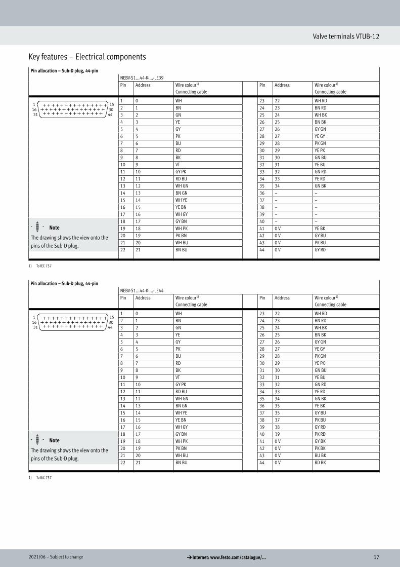
Pin allocation – Sub-D plug, 44-pinNEBV-S1...44-K-...-LE39Pin Address Wire colour1)
Connecting cable Pin Address Wire colour1)
Connecting cable
1 0 WH 23 22 WH RD2 1 BN 24 23 BN RD3 2 GN 25 24 WH BK4 3 YE 26 25 BN BK5 4 GY 27 26 GY GN6 5 PK 28 27 YE GY7 6 BU 29 28 PK GN8 7 RD 30 29 YE PK9 8 BK 31 30 GN BU10 9 VT 32 31 YE BU11 10 GY PK 33 32 GN RD12 11 RD BU 34 33 YE RD13 12 WH GN 35 34 GN BK14 13 BN GN 36 – –15 14 WH YE 37 – –16 15 YE BN 38 – –17 16 WH GY 39 – –
H- - Note
The drawing shows the view onto the pins of the Sub-D plug.
18 17 GY BN 40 – –19 18 WH PK 41 0 V YE BK20 19 PK BN 42 0 V GY BU21 20 WH BU 43 0 V PK BU22 21 BN BU 44 0 V GY RD
1) To IEC 757
Pin allocation – Sub-D plug, 44-pinNEBV-S1...44-K-...-LE44Pin Address Wire colour1)
Connecting cable Pin Address Wire colour1)
Connecting cable
1 0 WH 23 22 WH RD2 1 BN 24 23 BN RD3 2 GN 25 24 WH BK4 3 YE 26 25 BN BK5 4 GY 27 26 GY GN6 5 PK 28 27 YE GY7 6 BU 29 28 PK GN8 7 RD 30 29 YE PK9 8 BK 31 30 GN BU10 9 VT 32 31 YE BU11 10 GY PK 33 32 GN RD12 11 RD BU 34 33 YE RD13 12 WH GN 35 34 GN BK14 13 BN GN 36 35 YE BK15 14 WH YE 37 35 GY BU16 15 YE BN 38 37 PK BU17 16 WH GY 39 38 GY RD
H- - Note
The drawing shows the view onto the pins of the Sub-D plug.
18 17 GY BN 40 39 PK RD19 18 WH PK 41 0 V GY BK20 19 PK BN 42 0 V PK BK21 20 WH BU 43 0 V BU BK22 21 BN BU 44 0 V RD BK
1) To IEC 757

18 d Internet: www.festo.com/catalogue/... Subject to change – 2021/06
Valve terminals VTUB-12
Key features – Electrical components
Pin allocation – Adapter M8x1 with LEDPin
Round plug, M8, 3-pinVAVE-C8-1R81 Not used3 0V4 24 V
Round plug, M8, 4-pinVAVE-C8-1R11 Not used2 Not used3 0V4 24 V
Protective circuitManifold rail with I-Port interface
I-Port interface/IO-Link
The valve terminal VTUB-12 can be connected as follows via the I-Port:• Directly to the fieldbus by mounting
the CTEU bus node on the valve terminal
• To an IO-Link master (in IO-Link mode) via a cable
Up to 35 solenoid coils can be actuat-ed. A valve position always occupies one address. The following assignment applies in this case:• Less significant valve position
(address) for coil 14• More significant valve position
(address) for coil 12
Addresses are allocated in ascending order without gaps, from left to right. The address allocation is independent of whether blanking plates or valves are used.
H- - Note
More information on CTEUa cteuAdditionally required IODD for IO-Link modea www.festo.com
Pin allocation – I-Port interface/IO-Link1)
Pin Allocation
1 24 V electronics (logic voltage)
2 24 V valves (load voltage)
3 0 V electronics (logic)
4 COM I-Port communication signal
5 0 V valves (load)
1) Plug, 5-pin, M12, A-coded
192021/06 – Subject to change d Internet: www.festo.com/catalogue/...
Valve terminal VTUB-12
Instructions for use
System equipment
Operate your system with unlubricated compressed air if possible. Festo valves and cylinders are designed so that, if used as intended, they will not require additional lubrication and will still achieve a long service life.The quality of compressed air down-stream of the compressor must corre-spond to that of unlubricated com-pressed air. If possible, do not operate the entire system with lubricated com-pressed air. The lubricators should, where possible, always be installed directly upstream of the actuator requiring them.
Incorrect additional oil and too high an oil content in the compressed air reduce the service life of the valve terminal.Use Festo special oil OFSW-32 or the alternatives listed in the Festo catalogue (as specified in DIN 51524 HLP32; basic oil viscosity 32 CST at 40°C).
Bio-oilsWhen using bio-oils (oils which are based on synthetic or native esters, e.g. rapeseed oil methyl ester), the maximum residual oil content of 0.1 mg/m3 must not be exceeded (see ISO 8573-1 Class 2).
Mineral oilsWhen using mineral oils (e.g. HLP oils to DIN 51524, parts 1 to 3) or similar oils based on poly-alpha-olefins (PAO), the maximum residual oil content of 5 mg/m3 must not be exceeded (see ISO 8573-1 Class 4).A higher residual oil content is not per-mitted, regardless of the compressor oil, because the permanent lubrication would otherwise be flushed out over a period of time.
Instructions for use

20 d Internet: www.festo.com/catalogue/... Subject to change – 2021/06
Valve terminal VTUB-12
Data sheet – Valve terminal VTUB-12 with multi-pin plug connection
-P- Voltage 24 V DC
-L- Pressure 0.28 ... 0.8 MPa 2.8 ... 8 bar
-Q- Temperature range –5 ... 60°C
General technical dataValve function 3/2C 3/2U 5/2-way, single
solenoid5/2-way, double solenoid
Design Poppet valve with spring return Poppet valve with self-holding function
Valve function Closed Open Single solenoid Double solenoidSealing principle SoftActuation type ElectricalReset method Mechanical spring –Type of control PilotedPilot air supply Internal
ExternalFlow direction Non-reversibleExhaust air function Cannot be throttledManual override Non-detenting, non-detenting/detentingType of mounting With through-holeWidth [mm] 12 24Nominal width [mm] 4Max. no. of valve positions 35 35 17Max. number of pressure zones 18Standard nominal flow rate qnN [l/min] 400Pneumatic connection 1; 3; 5 G1/4
2; 4 QS-4 or QS-612; 14 G1/8
Operating and environmental conditionsValve function 3/2C 3/2U 5/2-way, single
solenoid5/2-way, double solenoid
Operating medium Compressed air to ISO 8573-1:2010 [7:4:4]Note on the operating/pilot medium Lubricated operation possible (in which case lubricated operation will always be required)Operating pressure Internal pilot air [MPa] 0.2 ... 0.8 0.28 ... 0.8
[bar] 2 ... 8 2.8 ... 8External pilot air [MPa] 0 ... 0.8
[bar] 0 ... 8Pilot pressure [MPa] 0.2 ... 0.8 0.28 ... 0.8
[bar] 2 ... 8 2.8 ... 8Ambient temperature [°C] –5 ... 60Temperature of medium [°C] –5 ... 60
*
Safety characteristics
CE marking (see declaration of conformity) To EU EMC DirectiveKC mark KC EMCMax. positive test pulse with 0 signal [ìs] 800
Max. negative test pulse with 1 signal [ìs] 300
Shock resistance Shock test with severity level 1 to FN 942017-5 and EN 60068-2-27Vibration resistance Transport application test with severity level 1 to FN 942017-4 and EN 60068-2-6Well-tried component Yes
Data sheet – Valve terminal VTUB-12
Technical data – Multi-pin plug connection
212021/06 – Subject to change d Internet: www.festo.com/catalogue/...
Valve terminal VTUB-12
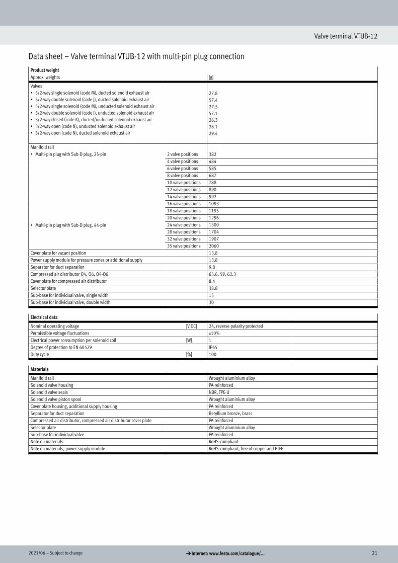
Data sheet – Valve terminal VTUB-12 with multi-pin plug connection
Product weightApprox. weights [g]
Valves• 5/2-way single solenoid (code M), ducted solenoid exhaust air• 5/2-way double solenoid (code J), ducted solenoid exhaust air• 5/2-way single solenoid (code M), unducted solenoid exhaust air• 5/2-way double solenoid (code J), unducted solenoid exhaust air• 3/2-way closed (code K), ducted/unducted solenoid exhaust air• 3/2-way open (code N), unducted solenoid exhaust air• 3/2-way open (code N), ducted solenoid exhaust air
27.857.427.557.126.328.129.4
Manifold rail382• Multi-pin plug with Sub-D plug, 25-pin
• Multi-pin plug with Sub-D plug, 44-pin
2 valve positions4 valve positions 4846 valve positions 5858 valve positions 68710 valve positions 78812 valve positions 89014 valve positions 99216 valve positions 109318 valve positions 119520 valve positions 129624 valve positions 150028 valve positions 170432 valve positions 190735 valve positions 2060
Cover plate for vacant position 13.8Power supply module for pressure zones or additional supply 13.8Separator for duct separation 9.8Compressed air distributor Q4, Q6, Q4-Q6 65.6, 59, 62.3Cover plate for compressed air distributor 8.4Selector plate 38.8Sub-base for individual valve, single width 15Sub-base for individual valve, double width 30
Electrical data
Nominal operating voltage [V DC] 24, reverse polarity protectedPermissible voltage fluctuations ±10%Electrical power consumption per solenoid coil [W] 1Degree of protection to EN 60529 IP65Duty cycle [%] 100
Materials
Manifold rail Wrought aluminium alloySolenoid valve housing PA-reinforcedSolenoid valve seals NBR, TPE-USolenoid valve piston spool Wrought aluminium alloyCover plate housing, additional supply housing PA-reinforcedSeparator for duct separation Beryllium bronze, brassCompressed air distributor, compressed air distributor cover plate PA-reinforcedSelector plate Wrought aluminium alloySub-base for individual valve PA-reinforcedNote on materials RoHS-compliantNote on materials, power supply module RoHS-compliant, free of copper and PTFE
22 d Internet: www.festo.com/catalogue/... Subject to change – 2021/06
Valve terminal VTUB-12
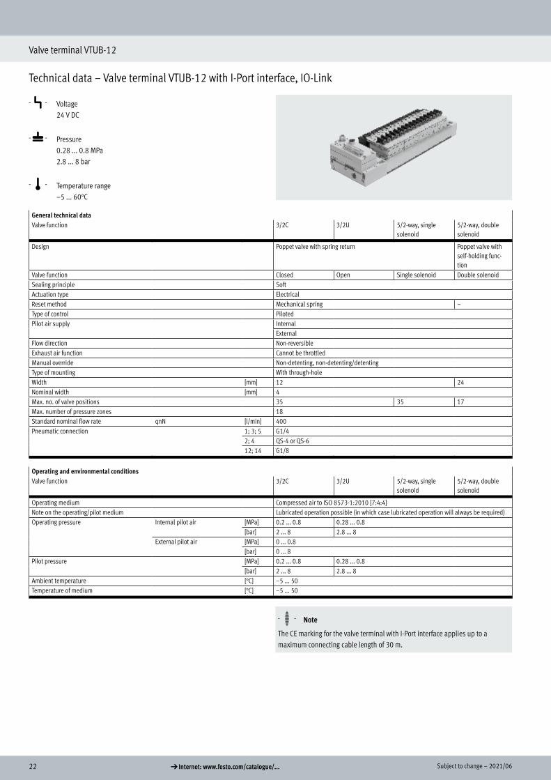
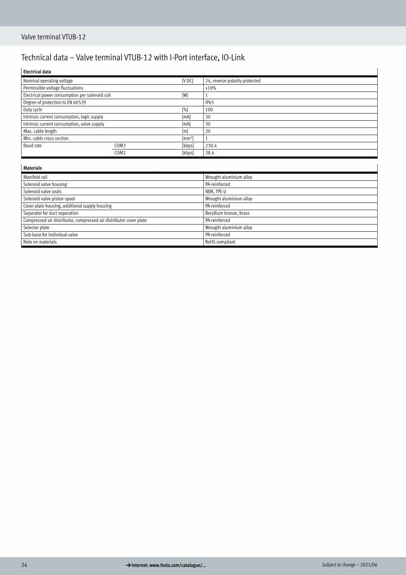
Technical data – Valve terminal VTUB-12 with I-Port interface, IO-Link
-P- Voltage 24 V DC
-L- Pressure 0.28 ... 0.8 MPa 2.8 ... 8 bar
-Q- Temperature range –5 ... 60°C
General technical dataValve function 3/2C 3/2U 5/2-way, single
solenoid5/2-way, double solenoid
Design Poppet valve with spring return Poppet valve with self-holding func-tion
Valve function Closed Open Single solenoid Double solenoidSealing principle SoftActuation type ElectricalReset method Mechanical spring –Type of control PilotedPilot air supply Internal
ExternalFlow direction Non-reversibleExhaust air function Cannot be throttledManual override Non-detenting, non-detenting/detentingType of mounting With through-holeWidth [mm] 12 24Nominal width [mm] 4Max. no. of valve positions 35 35 17Max. number of pressure zones 18Standard nominal flow rate qnN [l/min] 400Pneumatic connection 1; 3; 5 G1/4
2; 4 QS-4 or QS-612; 14 G1/8
Operating and environmental conditionsValve function 3/2C 3/2U 5/2-way, single
solenoid5/2-way, double solenoid
Operating medium Compressed air to ISO 8573-1:2010 [7:4:4]Note on the operating/pilot medium Lubricated operation possible (in which case lubricated operation will always be required)Operating pressure Internal pilot air [MPa] 0.2 ... 0.8 0.28 ... 0.8
[bar] 2 ... 8 2.8 ... 8External pilot air [MPa] 0 ... 0.8
[bar] 0 ... 8Pilot pressure [MPa] 0.2 ... 0.8 0.28 ... 0.8
[bar] 2 ... 8 2.8 ... 8Ambient temperature [°C] –5 ... 50Temperature of medium [°C] –5 ... 50
*
H- - Note
The CE marking for the valve terminal with I-Port interface applies up to a maximum connecting cable length of 30 m.
Technical data – I-Port interface, IO-Link
232021/06 – Subject to change d Internet: www.festo.com/catalogue/...
Valve terminal VTUB-12
Technical data – Valve terminal VTUB-12 with I-Port interface, IO-Link
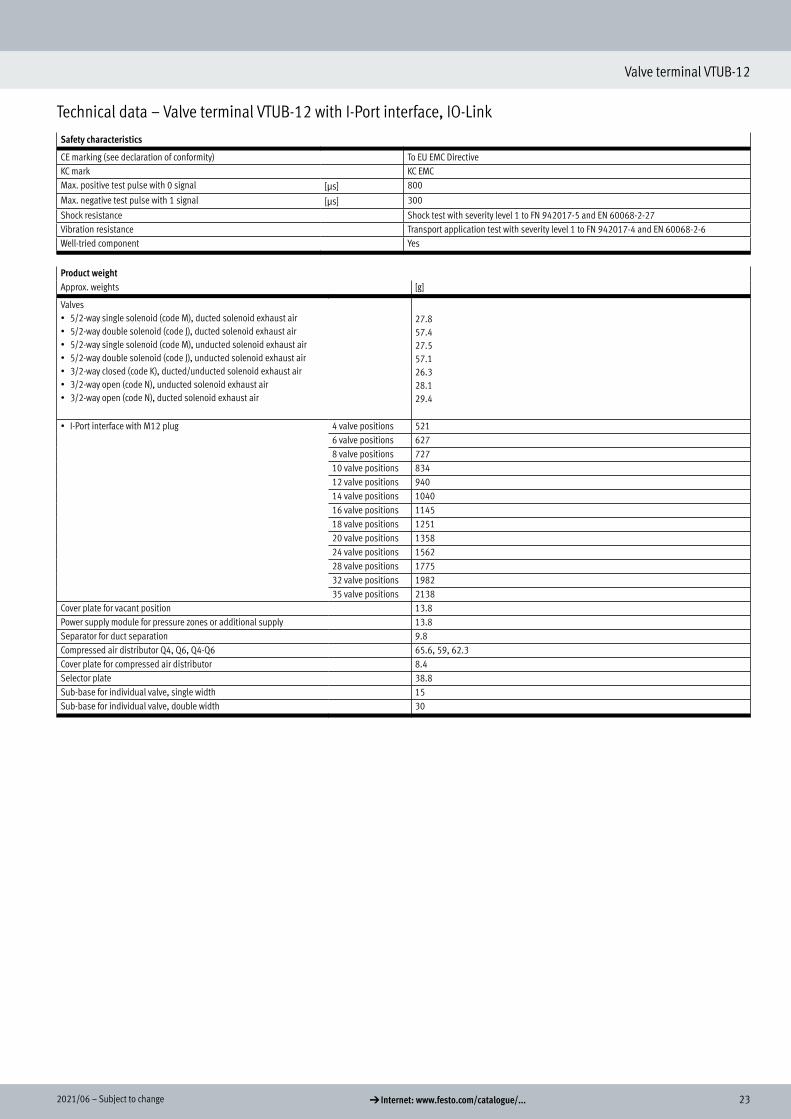
Safety characteristics
CE marking (see declaration of conformity) To EU EMC DirectiveKC mark KC EMCMax. positive test pulse with 0 signal [ìs] 800
Max. negative test pulse with 1 signal [ìs] 300
Shock resistance Shock test with severity level 1 to FN 942017-5 and EN 60068-2-27Vibration resistance Transport application test with severity level 1 to FN 942017-4 and EN 60068-2-6Well-tried component Yes
Product weightApprox. weights [g]
Valves• 5/2-way single solenoid (code M), ducted solenoid exhaust air• 5/2-way double solenoid (code J), ducted solenoid exhaust air• 5/2-way single solenoid (code M), unducted solenoid exhaust air• 5/2-way double solenoid (code J), unducted solenoid exhaust air• 3/2-way closed (code K), ducted/unducted solenoid exhaust air• 3/2-way open (code N), unducted solenoid exhaust air• 3/2-way open (code N), ducted solenoid exhaust air
27.857.427.557.126.328.129.4
• I-Port interface with M12 plug 4 valve positions 5216 valve positions 6278 valve positions 72710 valve positions 83412 valve positions 94014 valve positions 104016 valve positions 114518 valve positions 125120 valve positions 135824 valve positions 156228 valve positions 177532 valve positions 198235 valve positions 2138
Cover plate for vacant position 13.8Power supply module for pressure zones or additional supply 13.8Separator for duct separation 9.8Compressed air distributor Q4, Q6, Q4-Q6 65.6, 59, 62.3Cover plate for compressed air distributor 8.4Selector plate 38.8Sub-base for individual valve, single width 15Sub-base for individual valve, double width 30
24 d Internet: www.festo.com/catalogue/... Subject to change – 2021/06
Valve terminal VTUB-12
Technical data – Valve terminal VTUB-12 with I-Port interface, IO-Link
Electrical data
Nominal operating voltage [V DC] 24, reverse polarity protectedPermissible voltage fluctuations ±10%Electrical power consumption per solenoid coil [W] 1Degree of protection to EN 60529 IP65Duty cycle [%] 100Intrinsic current consumption, logic supply [mA] 30Intrinsic current consumption, valve supply [mA] 30Max. cable length [m] 20Min. cable cross section [mm2] 1Baud rate COM3 [kbps] 230.4
COM2 [kbps] 38.4
Materials
Manifold rail Wrought aluminium alloySolenoid valve housing PA-reinforcedSolenoid valve seals NBR, TPE-USolenoid valve piston spool Wrought aluminium alloyCover plate housing, additional supply housing PA-reinforcedSeparator for duct separation Beryllium bronze, brassCompressed air distributor, compressed air distributor cover plate PA-reinforcedSelector plate Wrought aluminium alloySub-base for individual valve PA-reinforcedNote on materials RoHS-compliant

252021/06 – Subject to change d Internet: www.festo.com/catalogue/...
Valve terminal VTUB-12
Data sheet
Valve switching times [ms]Valve function 3/2 5/2-way, single solenoid 5/2-way, double solenoid
On 6 6 –Off 14 14 –Changeover – – 10
Pilot pressure as a function of operating pressure(operating pressure with external pilot air),pilot pressure 5/2 and 3/2U
Pilot pressure as a function of operating pressure(operating pressure with external pilot air),pilot pressure 3/2C
VTUB-12
p1 [bar]
p2
[ba
r]
2 3 4 5 6 7 81 9 100
1
2
3
4
5
6
7
8
9
VTUB-12
p1 [bar]
p2
[ba
r]
2 3 4 5 6 7 81 9 100
1
2
3
4
5
6
7
8
9
Flow rate q per valve with multiple (n) valves switched simultaneously (tolerance ± 20%)
VTUB
n
q[l
/min
]
q[%
]
0 1 2 3 4 5 6 7 8 9 10 110
50
100
150
200
250
300
350
400
4500
-5
-10
-15
-20
-25
-30
-35
-40
-45
Flow rate per valveLoss per valve [%]

26 d Internet: www.festo.com/catalogue/... Subject to change – 2021/06
Valve terminals VTUB-12
Data sheet
MaterialsSectional view – Valves
1 2
Double solenoid Single solenoid
[1] Housing PA-reinforced[2] Piston slide Wrought aluminium alloy– Seals NBR, PUR– Manifold rail with multi-pin plug Wrought aluminium alloy– Power supply module PA-reinforced– Cover plate for vacant position PA-reinforced– Selector plate Wrought aluminium alloy
Dimensions – Power supply module Download CAD data a www.festo.com
[2] Retaining screw M2.5[3] Push-in connector QSP...10...-
Type B1 H1 H2 L1 L2 L3 L5
VABF-C8-12-P3A5-QX 11.7 29.4 23.9 89.9 87.3 57.8 27.1
Sectional view
Dimensions
272021/06 – Subject to change d Internet: www.festo.com/catalogue/...
Valve terminals VTUB-12
Data sheet
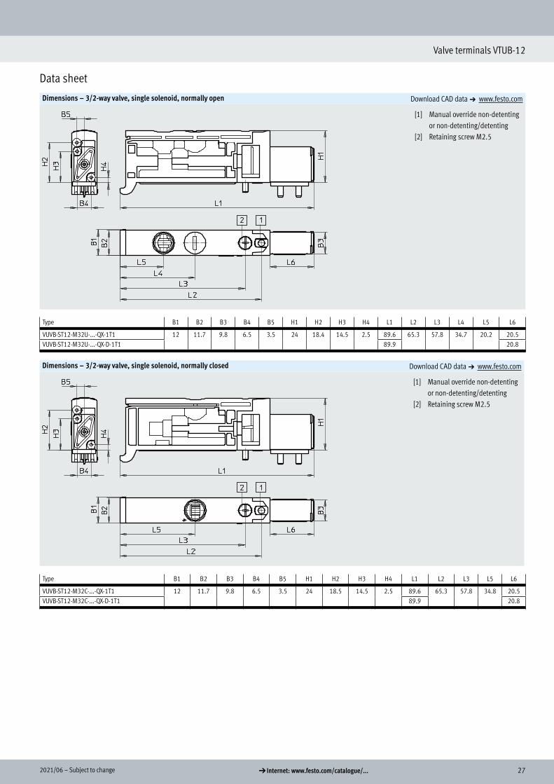
Dimensions – 3/2-way valve, single solenoid, normally open Download CAD data a www.festo.com
[1] Manual override non-detenting or non-detenting/detenting
[2] Retaining screw M2.5
Type B1 B2 B3 B4 B5 H1 H2 H3 H4 L1 L2 L3 L4 L5 L6
VUVB-ST12-M32U-...-QX-1T1 12 11.7 9.8 6.5 3.5 24 18.4 14.5 2.5 89.6 65.3 57.8 34.7 20.2 20.5VUVB-ST12-M32U-...-QX-D-1T1 89.9 20.8
Dimensions – 3/2-way valve, single solenoid, normally closed Download CAD data a www.festo.com
[1] Manual override non-detenting or non-detenting/detenting
[2] Retaining screw M2.5
Type B1 B2 B3 B4 B5 H1 H2 H3 H4 L1 L2 L3 L5 L6
VUVB-ST12-M32C-...-QX-1T1 12 11.7 9.8 6.5 3.5 24 18.5 14.5 2.5 89.6 65.3 57.8 34.8 20.5VUVB-ST12-M32C-...-QX-D-1T1 89.9 20.8
28 d Internet: www.festo.com/catalogue/... Subject to change – 2021/06
Valve terminals VTUB-12
Data sheet
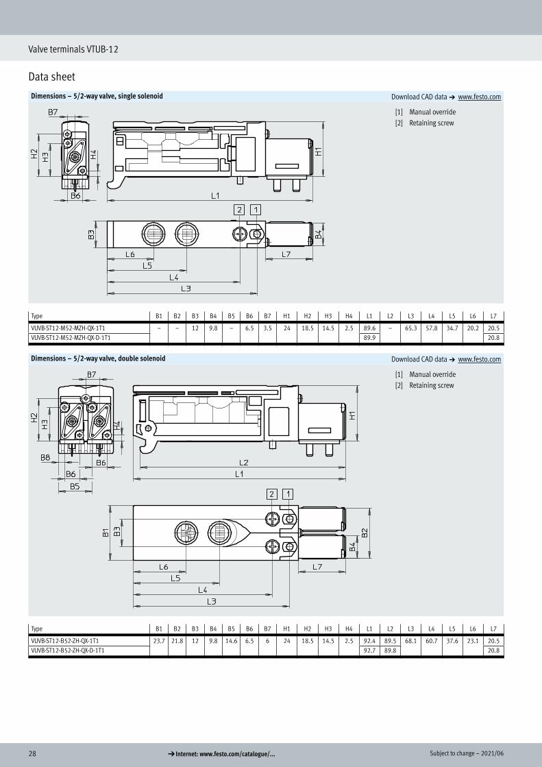
Dimensions – 5/2-way valve, single solenoid Download CAD data a www.festo.com
[1] Manual override[2] Retaining screw
Type B1 B2 B3 B4 B5 B6 B7 H1 H2 H3 H4 L1 L2 L3 L4 L5 L6 L7
VUVB-ST12-M52-MZH-QX-1T1 – – 12 9.8 – 6.5 3.5 24 18.5 14.5 2.5 89.6 – 65.3 57.8 34.7 20.2 20.5VUVB-ST12-M52-MZH-QX-D-1T1 89.9 20.8
Dimensions – 5/2-way valve, double solenoid Download CAD data a www.festo.com
[1] Manual override[2] Retaining screw
Type B1 B2 B3 B4 B5 B6 B7 H1 H2 H3 H4 L1 L2 L3 L4 L5 L6 L7
VUVB-ST12-B52-ZH-QX-1T1 23.7 21.8 12 9.8 14.6 6.5 6 24 18.5 14.5 2.5 92.4 89.5 68.1 60.7 37.6 23.1 20.5VUVB-ST12-B52-ZH-QX-D-1T1 92.7 89.8 20.8

292021/06 – Subject to change d Internet: www.festo.com/catalogue/...
Valve terminals VTUB-12
Data sheet
Dimensions – Manifold rail with multi-pin plug Download CAD data a www.festo.com
n Number of valve positions (2...35)
Type B1 B2 B3 B4 B5 B6 B7 D1 D2 H1 H2 H3 H4
VABM-C8-12E 100 87 61.5 55.9 31.5 31.5 14.5 G1/4 5.5 49.3 42.2 33 14.5
Type L1 L2 L3 L4 L5 L6 L7 L8 L9
VABM-C8-12E (nx12)+107 (nx12)+20 (nx12)+11 41.5 36 20 12 10 4.5
30 d Internet: www.festo.com/catalogue/... Subject to change – 2021/06
Valve terminals VTUB-12
Data sheet
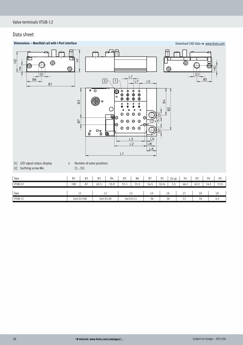
Dimensions – Manifold rail with I-Port interface Download CAD data a www.festo.com
[1] LED signal status display[2] Earthing screw M4
n Number of valve positions (3...35)
Type B1 B2 B3 B4 B5 B6 B7 D1 D2-N- H1 H2 H4 H5
VTUB-12 100 87 61.5 55.9 31.5 31.5 14.5 G1/4 5.5 46.1 42.2 14.5 13.5
Type L1 L2 L3 L5 L6 L7 L8 L9
VTUB-12 (nx12)+100 (nx12)+20 (nx12)+11 36 20 12 10 4.5
312021/06 – Subject to change d Internet: www.festo.com/catalogue/...
Valve terminals VTUB-12
Data sheet
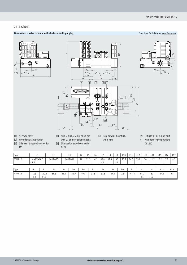
Dimensions – Valve terminal with electrical multi-pin plug Download CAD data a www.festo.com
[1] 5/2-way valve[2] Cover for vacant position[3] Silencer / threaded connection
M5
[4] Sub-D plug, 25-pin, or 44-pin with 21 or more solenoid coils
[5] Silencer/threaded connection G1/4
[6] Hole for wall mounting, @ 5.5 mm
[7] Fittings for air supply portn Number of valve positions
(2...35)
Type L1 L2 L3 L4 L5 L6 L7 L8 L9 L10 L11 L12 L13 L14 L15 L16 L17
VTUB-12 (nx12)+107± 1.5
(nx12)+20 (nx12)+11 78 71.5 67 32.4± 1
42.5 40± 1
25.7 24.5 23.7 20 11.7 10.2 7.2 4.5
Type B1 B2 B3 B4 B5 B6 B7 B8 B9 B10 D1 H1 H2 H12 H13
VTUB-12 103 ± 2
100.4± 1.1
86.5 61.5 55.9 40.5 31.5 31.5 14.5 2.8 G1/4 88.2± 1
82± 1
14.5 2.5

32 d Internet: www.festo.com/catalogue/... Subject to change – 2021/06
Valve terminals VTUB-12
Data sheet
Dimensions – Valve terminal with I-Port interface, CTEU bus node Download CAD data a www.festo.com
[1] Earthing screw, M4[2] M12 plug, 5-pin[3] Silencer, threaded connection
M5[4] Holes for mounting, @ 5.5
[5] Silencer, threaded connection G1/4
[6] Fittings for air supply port
[7] External pilot air 12/14, G1/8[8] Bus node CTEU
n Number of valve positions (3...35)
Type B2 B3 B4 B5 B7 B8 B9 B10 D1 H1 H2 H11 H12 H13
VTUB-12 100 87 61.5 55.9 31.3 31.5 14.5 3 G1/4 88.2 82 14.5 13.5 2.5
Type L1 L2 L3 L4 L5 L6 L9 L11 L12 L13 L14 L15 L16 L17
VTUB-12 (nx12)+100 (nx12)+20 (nx12)+11 78 64.5 60 40 24.5 23.7 20 11.7 10.2 7.2 4.5

332021/06 – Subject to change d Internet: www.festo.com/catalogue/...
Valve terminals VTUB-12
Data sheet
Dimensions – Sub-base for semi in-line valve (single solenoid) Download CAD data a www.festo.com
[1] Connecting cable (optional)
[2] Adapter M8x1 (optional)[3] Port 2, 4: Cartridge with push-in
connector
[4] Connecting cable NEBV or KMYZ (optional)
[5] Port 12, 14: Cartridge with push-in connector (optional)
[6] Port 1: Cartridge with push-in connector
[7] Port 3, 5: Silencer AMTC-P-PC10 (optional)
[8] Holes for M4 mounting
[9] Exhaust air 82/84[10] Mounting space for spring clips
for solenoid valve[11] Mounting space for spring clips
for sub-base[12] Slot for inscription label
IBS- 6x10 (not included in scope of delivery)
Type B1 B2 H1 H2 H3 H4 H5 H6 L1 L2 L3 L4 L5 L6 L7 L8 L9 L10 L11 L12 W1
VABS-C8-12XB-QX-B 12.6 11.9 34.9 30.6 17.9 15.5 11 6.9 94.5 82.9 57.3 50 37.3 30 22.8 15.5 9.5 8.3 82 51 60°VABS-C8-12XB-QX
34 d Internet: www.festo.com/catalogue/... Subject to change – 2021/06
Valve terminals VTUB-12
Data sheet
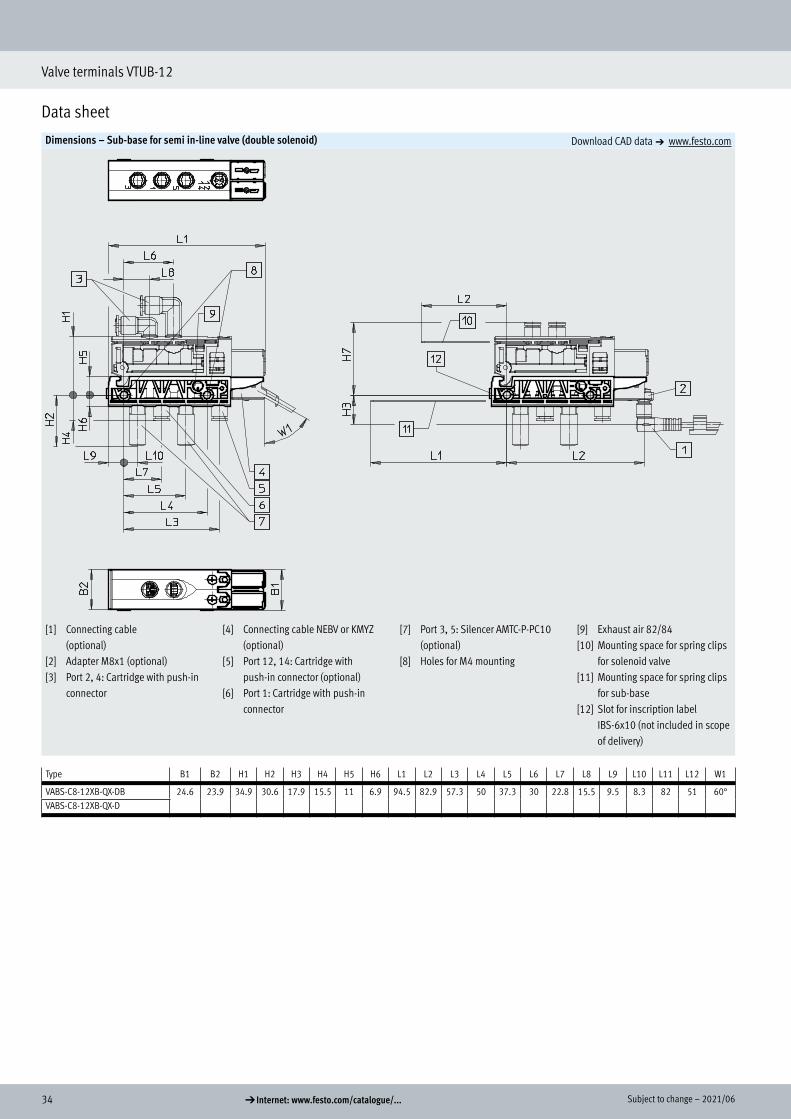
Dimensions – Sub-base for semi in-line valve (double solenoid) Download CAD data a www.festo.com
[1] Connecting cable (optional)
[2] Adapter M8x1 (optional)[3] Port 2, 4: Cartridge with push-in
connector
[4] Connecting cable NEBV or KMYZ (optional)
[5] Port 12, 14: Cartridge with push-in connector (optional)
[6] Port 1: Cartridge with push-in connector
[7] Port 3, 5: Silencer AMTC-P-PC10 (optional)
[8] Holes for M4 mounting
[9] Exhaust air 82/84[10] Mounting space for spring clips
for solenoid valve[11] Mounting space for spring clips
for sub-base[12] Slot for inscription label
IBS-6x10 (not included in scope of delivery)
Type B1 B2 H1 H2 H3 H4 H5 H6 L1 L2 L3 L4 L5 L6 L7 L8 L9 L10 L11 L12 W1
VABS-C8-12XB-QX-DB 24.6 23.9 34.9 30.6 17.9 15.5 11 6.9 94.5 82.9 57.3 50 37.3 30 22.8 15.5 9.5 8.3 82 51 60°VABS-C8-12XB-QX-D
352021/06 – Subject to change d Internet: www.festo.com/catalogue/...
Valve terminal VTUB-12
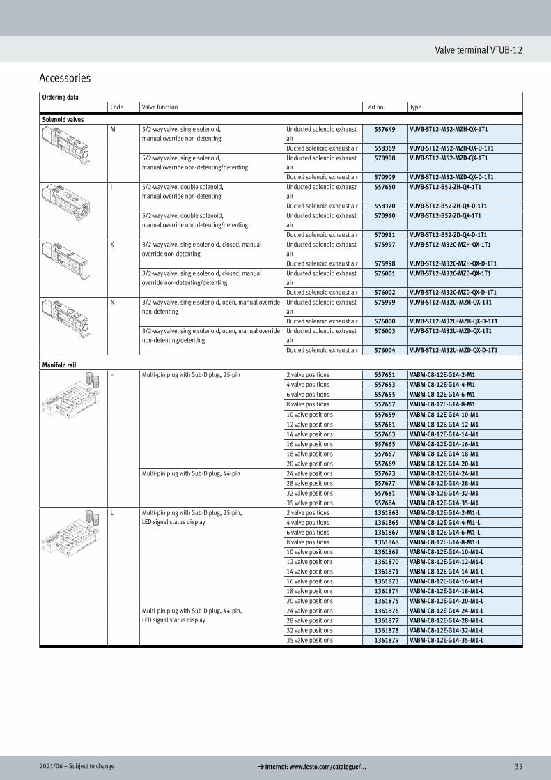
Accessories
Ordering dataCode Valve function Part no. Type
Solenoid valvesM 5/2-way valve, single solenoid,
manual override non-detentingUnducted solenoid exhaust air
557649 VUVB-ST12-M52-MZH-QX-1T1
Ducted solenoid exhaust air 558369 VUVB-ST12-M52-MZH-QX-D-1T15/2-way valve, single solenoid,manual override non-detenting/detenting
Unducted solenoid exhaust air
570908 VUVB-ST12-M52-MZD-QX-1T1
Ducted solenoid exhaust air 570909 VUVB-ST12-M52-MZD-QX-D-1T1J 5/2-way valve, double solenoid,
manual override non-detentingUnducted solenoid exhaust air
557650 VUVB-ST12-B52-ZH-QX-1T1
Ducted solenoid exhaust air 558370 VUVB-ST12-B52-ZH-QX-D-1T15/2-way valve, double solenoid,manual override non-detenting/detenting
Unducted solenoid exhaust air
570910 VUVB-ST12-B52-ZD-QX-1T1
Ducted solenoid exhaust air 570911 VUVB-ST12-B52-ZD-QX-D-1T1K 3/2-way valve, single solenoid, closed, manual
override non-detentingUnducted solenoid exhaust air
575997 VUVB-ST12-M32C-MZH-QX-1T1
Ducted solenoid exhaust air 575998 VUVB-ST12-M32C-MZH-QX-D-1T13/2-way valve, single solenoid, closed, manual override non-detenting/detenting
Unducted solenoid exhaust air
576001 VUVB-ST12-M32C-MZD-QX-1T1
Ducted solenoid exhaust air 576002 VUVB-ST12-M32C-MZD-QX-D-1T1N 3/2-way valve, single solenoid, open, manual override
non-detentingUnducted solenoid exhaust air
575999 VUVB-ST12-M32U-MZH-QX-1T1
Ducted solenoid exhaust air 576000 VUVB-ST12-M32U-MZH-QX-D-1T13/2-way valve, single solenoid, open, manual override non-detenting/detenting
Unducted solenoid exhaust air
576003 VUVB-ST12-M32U-MZD-QX-1T1
Ducted solenoid exhaust air 576004 VUVB-ST12-M32U-MZD-QX-D-1T1
Manifold rail– Multi-pin plug with Sub-D plug, 25-pin 2 valve positions 557651 VABM-C8-12E-G14-2-M1
4 valve positions 557653 VABM-C8-12E-G14-4-M16 valve positions 557655 VABM-C8-12E-G14-6-M18 valve positions 557657 VABM-C8-12E-G14-8-M110 valve positions 557659 VABM-C8-12E-G14-10-M112 valve positions 557661 VABM-C8-12E-G14-12-M114 valve positions 557663 VABM-C8-12E-G14-14-M116 valve positions 557665 VABM-C8-12E-G14-16-M118 valve positions 557667 VABM-C8-12E-G14-18-M120 valve positions 557669 VABM-C8-12E-G14-20-M1
Multi-pin plug with Sub-D plug, 44-pin 24 valve positions 557673 VABM-C8-12E-G14-24-M128 valve positions 557677 VABM-C8-12E-G14-28-M132 valve positions 557681 VABM-C8-12E-G14-32-M135 valve positions 557684 VABM-C8-12E-G14-35-M1
L Multi-pin plug with Sub-D plug, 25-pin, LED signal status display
2 valve positions 1361863 VABM-C8-12E-G14-2-M1-L4 valve positions 1361865 VABM-C8-12E-G14-4-M1-L6 valve positions 1361867 VABM-C8-12E-G14-6-M1-L8 valve positions 1361868 VABM-C8-12E-G14-8-M1-L10 valve positions 1361869 VABM-C8-12E-G14-10-M1-L12 valve positions 1361870 VABM-C8-12E-G14-12-M1-L14 valve positions 1361871 VABM-C8-12E-G14-14-M1-L16 valve positions 1361873 VABM-C8-12E-G14-16-M1-L18 valve positions 1361874 VABM-C8-12E-G14-18-M1-L20 valve positions 1361875 VABM-C8-12E-G14-20-M1-L
Multi-pin plug with Sub-D plug, 44-pin,LED signal status display
24 valve positions 1361876 VABM-C8-12E-G14-24-M1-L28 valve positions 1361877 VABM-C8-12E-G14-28-M1-L32 valve positions 1361878 VABM-C8-12E-G14-32-M1-L35 valve positions 1361879 VABM-C8-12E-G14-35-M1-L
Ordering data
Solenoid valves
Manifold rail

36 d Internet: www.festo.com/catalogue/... Subject to change – 2021/06
Valve terminals VTUB-12
Accessories
Ordering dataCode Description Part no. Type
Manifold railPT/LK Manifold rail with I-Port interface 4 valve positions 1247975 VABM-C8-12E-G14-4-PT-L
6 valve positions 1247976 VABM-C8-12E-G14-6-PT-L8 valve positions 1247977 VABM-C8-12E-G14-8-PT-L10 valve positions 1247978 VABM-C8-12E-G14-10-PT-L12 valve positions 1247979 VABM-C8-12E-G14-12-PT-L14 valve positions 1247980 VABM-C8-12E-G14-14-PT-L16 valve positions 1247981 VABM-C8-12E-G14-16-PT-L18 valve positions 1247982 VABM-C8-12E-G14-18-PT-L20 valve positions 1247983 VABM-C8-12E-G14-20-PT-L24 valve positions 1247984 VABM-C8-12E-G14-24-PT-L28 valve positions 1247985 VABM-C8-12E-G14-28-PT-L32 valve positions 1247986 VABM-C8-12E-G14-32-PT-L35 valve positions 1247987 VABM-C8-12E-G14-35-PT-L
Sub-base for individual valve– For single solenoid valves Internal pilot air supply 1236025 VABS-C8-12XB-QX-B
External pilot air supply 1236027 VABS-C8-12XB-QX
– For double solenoid valves Internal pilot air supply 1236028 VABS-C8-12XB-QX-DBExternal pilot air supply 1236029 VABS-C8-12XB-QX-D
Power supply module S For additional air supply or for supplying pressure zones (operating pressure 0 ... 0.8 MPa),
pneumatic connection prepared for cartridge1894888 VABF-C8-12-P3A5-QX
Cover plateL Cover plate for vacant valve position 562461 VABB-C8-12-ET
– Cover plate for compressed air distributor position 562460 VABB-C8-12-A
Compressed air distributorAL Push-in connector 4 mm 562457 VABF-C8-12-V1P4-Q4BL Push-in connector 6 mm 562458 VABF-C8-12-V1P4-Q6CL Push-in connector 4 and 6 mm 562459 VABF-C8-12-V1P4-Q4-Q6
Power supply module
Cover plate
Compressed air distributor
372021/06 – Subject to change d Internet: www.festo.com/catalogue/...
Valve terminals VTUB-12
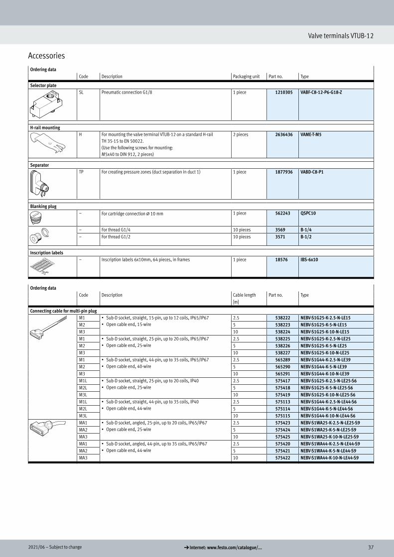
Accessories
Ordering dataCode Description Packaging unit Part no. Type
Selector plate SL Pneumatic connection G1/8 1 piece 1210305 VABF-C8-12-P6-G18-Z
H-rail mounting H For mounting the valve terminal VTUB-12 on a standard H-rail
TH 35-15 to EN 50022.(Use the following screws for mounting: M5x40 to DIN 912, 2 pieces)
2 pieces 2636436 VAME-T-M5
Separator TP For creating pressure zones (duct separation in duct 1) 1 piece 1877936 VABD-C8-P1
Blanking plug – For cartridge connection @ 10 mm 1 piece 562243 QSPC10
– For thread G1/4 10 pieces 3569 B-1/4– For thread G1/2 10 pieces 3571 B-1/2
Inscription labels – Inscription labels 6x10mm, 64 pieces, in frames 1 piece 18576 IBS-6x10
Ordering dataCode Description Cable length Part no. Type
[m]
Connecting cable for multi-pin plug M1 • Sub-D socket, straight, 15-pin, up to 12 coils, IP65/IP67
• Open cable end, 15-wire2.5 538222 NEBV-S1G25-K-2.5-N-LE15
M2 5 538223 NEBV-S1G25-K-5-N-LE15M3 10 538224 NEBV-S1G25-K-10-N-LE15M1 • Sub-D socket, straight, 25-pin, up to 20 coils, IP65/IP67
• Open cable end, 25-wire2.5 538225 NEBV-S1G25-K-2.5-N-LE25
M2 5 538226 NEBV-S1G25-K-5-N-LE25M3 10 538227 NEBV-S1G25-K-10-N-LE25M1 • Sub-D socket, straight, 44-pin, up to 35 coils, IP65/IP67
• Open cable end, 40-wire2.5 565289 NEBV-S1G44-K-2.5-N-LE39
M2 5 565290 NEBV-S1G44-K-5-N-LE39M3 10 565291 NEBV-S1G44-K-10-N-LE39M1L • Sub-D socket, straight, 25-pin, up to 20 coils, IP40
• Open cable end, 25-wire2.5 575417 NEBV-S1G25-K-2.5-N-LE25-S6
M2L 5 575418 NEBV-S1G25-K-5-N-LE25-S6M3L 10 575419 NEBV-S1G25-K-10-N-LE25-S6M1L • Sub-D socket, straight, 44-pin, up to 35 coils, IP40
• Open cable end, 44-wire2.5 575113 NEBV-S1G44-K-2.5-N-LE44-S6
M2L 5 575114 NEBV-S1G44-K-5-N-LE44-S6M3L 10 575115 NEBV-S1G44-K-10-N-LE44-S6MA1 • Sub-D socket, angled, 25-pin, up to 20 coils, IP65/IP67
• Open cable end, 25-wire2.5 575423 NEBV-S1WA25-K-2.5-N-LE25-S9
MA2 5 575424 NEBV-S1WA25-K-5-N-LE25-S9MA3 10 575425 NEBV-S1WA25-K-10-N-LE25-S9MA1 • Sub-D socket, angled, 44-pin, up to 35 coils, IP65/IP67
• Open cable end, 44-wire2.5 575420 NEBV-S1WA44-K-2.5-N-LE44-S9
MA2 5 575421 NEBV-S1WA44-K-5-N-LE44-S9MA3 10 575422 NEBV-S1WA44-K-10-N-LE44-S9
Selector plateH-rail mountingSeparatorBlanking plugInscription labelsConnecting cable for multi-pin plug
38 d Internet: www.festo.com/catalogue/... Subject to change – 2021/06
Valve terminals VTUB-12
Accessories
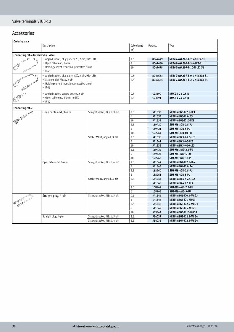
Ordering dataDescription Cable length Part no. Type
[m]
Connecting cable for individual valve• Angled socket, plug pattern ZC, 2-pin, with LED• Open cable end, 2-wire• Holding current reduction, protective circuit• IP65
2.5 8047679 NEBV-Z4WA2L-R-E-2.5-N-LE2-S15 8047680 NEBV-Z4WA2L-R-E-5-N-LE2-S110 8047678 NEBV-Z4WA2L-R-E-10-N-LE2-S1
• Angled socket, plug pattern ZC, 2-pin, with LED• Straight plug M8x1, 3-pin• Holding current reduction, protective circuit• IP65
0.5 8047683 NEBV-Z4WA2L-R-E-0.5-N-M8G3-S12.5 8047684 NEBV-Z4WA2L-R-E-2.5-N-M8G3-S1
• Angled socket, square design, 2-pin• Open cable end, 2-wire, no LED• IP50
0.5 193690 KMYZ-4-24-0.5-B2.5 193691 KMYZ-4-24-2.5-B
Connecting cableOpen cable end, 3-wire Straight socket, M8x1, 3-pin 2.5 541333 NEBU-M8G3-K-2.5-LE3
5 541334 NEBU-M8G3-K-5-LE310 541332 NEBU-M8G3-K-10-LE32.5 159420 SIM-M8-3GD-2.5-PU5 159421 SIM-M8-3GD-5-PU10 192964 SIM-M8-3GD-10-PU
Socket M8x1, angled, 3-pin 2.5 541338 NEBU-M8W3-K-2.5-LE35 541341 NEBU-M8W3-K-5-LE310 541335 NEBU-M8W3-K-10-LE32.5 159422 SIM-M8-3WD-2.5-PU5 159423 SIM-M8-3WD-5-PU10 192965 SIM-M8-3WD-10-PU
Open cable end, 4-wire Straight socket, M8x1, 4-pin 2.5 541342 NEBU-M8G4-K-2.5-LE45 541343 NEBU-M8G4-K-5-LE42.5 158960 SIM-M8-4GD-2.5-PU5 158961 SIM-M8-4GD-5-PU
Socket M8x1, angled, 4-pin 2.5 541344 NEBU-M8W4-K-2.5-LE45 541345 NEBU-M8W4-K-5-LE42.5 158962 SIM-M8-4WD-2.5-PU5 158963 SIM-M8-4WD-5-PU
Straight plug, 3-pin Straight socket, M8x1, 3-pin 0.5 541346 NEBU-M8G3-K-0.5-M8G31 541347 NEBU-M8G3-K-1-M8G32.5 541348 NEBU-M8G3-K-2.5-M8G35 541349 NEBU-M8G3-K-5-M8G310 569844 NEBU-M8G3-K-10-M8G3
Straight plug, 4-pin Straight socket, M8x1, 3-pin 2.5 554037 NEBU-M8G3-K-2.5-M8G4Straight socket, M8x1, 4-pin 2.5 554035 NEBU-M8G4-K-2.5-M8G4

392021/06 – Subject to change d Internet: www.festo.com/catalogue/...
Valve terminals VTUB-12
Accessories
Ordering dataDescription Tubing O.D. Packaging unit Part no. Type
Push-in fitting Data sheets a Internet: quick starWith sealing ringConnection G1/4
8 mm 10 pieces 186099 QS-G1/4-810 mm 10 pieces 186101 QS-G1/4-1012 mm 10 pieces 186350 QS-G1/4-12
Push-in L-fitting Data sheets a Internet: quick starWith sealing ringConnection G1/4
8 mm 10 pieces 186120 QSL-G1/4-810 mm 10 pieces 186122 QSL-G1/4-1012 mm 10 pieces 186351 QSL-G1/4-12
Push-in L-fitting, long Data sheets a Internet: quick starWith sealing ringConnection G1/4
8 mm 10 pieces 186131 QSLL-G1/4-810 mm 10 pieces 186133 QSLL-G1/4-1012 mm 10 pieces 132596 QSLL-G1/4-12
Cartridge with push-in connector StraightConnection @ 10 mm
4 mm 10 pieces 172972 QSP10-46 mm 10 pieces 172973 QSP10-6
L-shapeConnection @ 10 mm
4 mm 10 pieces 132601 QSPLK10-46 mm 10 pieces 132602 QSPLK10-6
L-shape, longConnection @ 10 mm
4 mm 10 pieces 132603 QSPLLK10-46 mm 10 pieces 132604 QSPLLK10-6
Silencer Data sheets a Internet: uFor thread G1/4 1 piece 2316 U-1/4
For individual sub-base, for cartridge connection @ 10 mm 1 piece 1224460 AMTC-P-P10
Push-in fitting
Push-in L-fitting
Push-in L-fitting, long
Cartridge with push-in connector
Silencer
40 d Internet: www.festo.com/catalogue/... Subject to change – 2021/06
Valve terminals VTUB-12
Accessories
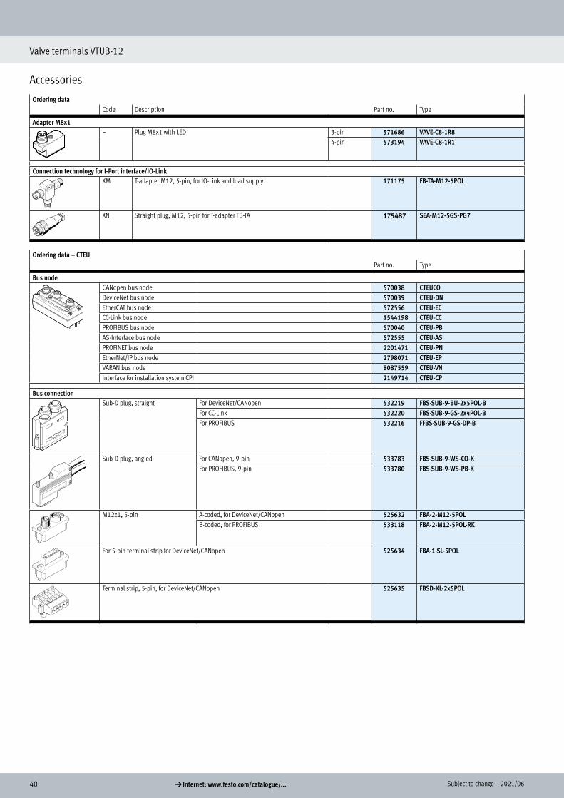
Ordering dataCode Description Part no. Type
Adapter M8x1 – Plug M8x1 with LED 3-pin 571686 VAVE-C8-1R8
4-pin 573194 VAVE-C8-1R1
Connection technology for I-Port interface/IO-Link XM T-adapter M12, 5-pin, for IO-Link and load supply 171175 FB-TA-M12-5POL
XN Straight plug, M12, 5-pin for T-adapter FB-TA 175487 SEA-M12-5GS-PG7
Ordering data – CTEUPart no. Type
Bus node CANopen bus node 570038 CTEU CODeviceNet bus node 570039 CTEU-DNEtherCAT bus node 572556 CTEU-ECCC-Link bus node 1544198 CTEU-CCPROFIBUS bus node 570040 CTEU-PBAS-Interface bus node 572555 CTEU-ASPROFINET bus node 2201471 CTEU-PNEtherNet/IP bus node 2798071 CTEU-EPVARAN bus node 8087559 CTEU-VNInterface for installation system CPI 2149714 CTEU-CP
Bus connection Sub-D plug, straight For DeviceNet/CANopen 532219 FBS-SUB-9-BU-2x5POL-B
For CC-Link 532220 FBS-SUB-9-GS-2x4POL-BFor PROFIBUS 532216 FFBS-SUB-9-GS-DP-B
Sub-D plug, angled For CANopen, 9-pin 533783 FBS-SUB-9-WS-CO-KFor PROFIBUS, 9-pin 533780 FBS-SUB-9-WS-PB-K
M12x1, 5-pin A-coded, for DeviceNet/CANopen 525632 FBA-2-M12-5POLB-coded, for PROFIBUS 533118 FBA-2-M12-5POL-RK
For 5-pin terminal strip for DeviceNet/CANopen 525634 FBA-1-SL-5POL
Terminal strip, 5-pin, for DeviceNet/CANopen 525635 FBSD-KL-2x5POL
Adapter M8x1
Connection technology for IO-Link
Bus node
Bus connection

412021/06 – Subject to change d Internet: www.festo.com/catalogue/...
Valve terminals VTUB-12
Accessories
Ordering data – CTEUPart no. Type
Bus connectionSocket, M12x1, 5-pin, for DeviceNet/CANopen 18324 FBSD-GD-9-5POLPlug, M12x1, 5-pin, for DeviceNet/CANopen 175380 FBS-M12-5GS-PG9
Straight socket, M12x1, 5-pin, for assembling a connecting cable compatible with FBA-2-M12-5POL-RK for PROFIBUS
1067905 NECU-M-B12G5-C2-PB
Straight plug, M12x1, 5-pin, for assembling a connecting cable compatible with FBA-2-M12-5POL-RK for PROFIBUS
1066354 NECU-M-S-B12G5-C2-PB
Terminating resistor, M12, B-coded for PROFIBUS 1072128 CACR-S-B12G5-220-PB
Plug M12x1, 4-pin, D-coded for EtherCAT 543109 NECU-M-S-D12G4-C2-ET
Electrical connection block For connecting a second device with I-Port interface 570042 CAPC-F1-E-M12
H-rail mounting For electrical connection block CAPC 570043 CAFM-F1-H
Connecting cables • Straight socket, M12x1, 5-pin• Straight plug, M12x1, 5-pin• Nominal conductor cross section 1 mm2
5 m 574321 NEBU-M12G5-E-5-Q8N-M12G57.5 m 574322 NEBU-M12G5-E-7.5-Q8N-M12G510 m 574323 NEBU-M12G5-E-10-Q8N-M12G5
• Angled socket, M12x1, 5-pin• Angled plug, M12x1, 5-pin
0.5 m 570733 NEBU-M12W5-K-0.5-M12W52 m 570734 NEBU-M12W5-K-2-M12W5
• Straight socket, M12x1, 5-pin• Angled plug, M12x1, 5-pin
0.5 m 8003617 NEBU-M12G5-K-0.5-M12W52 m 8003618 NEBU-M12G5-K-2-M12W5
Plug socket For power supply, M12x1, 5-pin, B-coded for CANopen/DeviceNet 538999 NTSD-GD-9-M12-5POL-RKFor power supply, M12x1, 5-pin for CC-Link, PROFIBUS, EtherCAT 18324 FBSD-GD-9-5POL
Inscription label For bus node, pack of 200 (5 frames each with 40 labels) 565306 ASLR-C-E4
Electrical connection block
H-rail mounting
Connecting cables
Plug socket
Inscription label