Burrs – Analysis, Control and...
25
Burrs – Analysis, Control and Removal
Transcript of Burrs – Analysis, Control and...

Burrs – Analysis, Control and Removal

Jan C. Aurich · David DornfeldEditors
Burrs – Analysis,Control and Removal
Proceedings of the CIRPInternational Conference on Burrs,2nd–3rd April, 2009,University of Kaiserslautern, Germany
123

Editors
Prof. Jan C. AurichUniversity of KaiserslauternInstitute for Manufacturing Technology and Production Systems - FBKGottlieb-Daimler-Straße67663 [email protected]
Prof. David DornfeldUniversity of California at BerkeleyDepartment of Mechanical Engineering5100A Etcheverry HallBerkeley, CA [email protected]
ISBN 978-3-642-00567-1 e-ISBN 978-3-642-00568-8DOI 10.1007/978-3-642-00568-8Springer Heidelberg Dordrecht London New York
Library of Congress Control Number: 2009926960
© Springer-Verlag Berlin Heidelberg 2010This work is subject to copyright. All rights are reserved, whether the whole or part of the material is concerned,specifically the rights of translation, reprinting, reuse of illustrations, recitation, broadcasting, reproduction onmicrofilm or in any other way, and storage in data banks. Duplication of this publication or parts thereof is permittedonly under the provisions of the German Copyright Law of September 9, 1965, in its current version, and permissionfor use must always be obtained from Springer. Violations are liable to prosecution under the German Copyright Law.The use of general descriptive names, registered names, trademarks, etc. in this publication does not imply, even inthe absence of a specific statement, that such names are exempt from the relevant protective laws and regulations andtherefore free for general use.
Cover design: eStudio Calamar S.L.
Printed on acid-free paper
Springer is part of Springer Science+Business Media (www.springer.com)

Preface
The International Conference on Analysis, Control and Removal of Burrs, held at theUniversity of Kaiserslautern, Germany, marks the end of the three-year cycle of the CIRPworking group on Burrs. During these years, researchers as well as experts from industry havecontributed and gathered knowledge on research and industrial practice in the area of burrs,edge conditions and part cleanliness. A CIRP round robin has been carried out with participantsin many countries and three continents to compare available methods on burr measurement.
This conference now brings together the members of the working group as well as expertsfrom industry and academia from all over the world to discuss the state of the art in researchas well as industrial applications in the area of burrs in one focused conference with a specialworkshop character. The conference shall provide a forum for the intense exchange of conceptsand methods, the dissemination of technological breakthroughs, and for discussions of futuredirections of research and development.
The conference program covers a broad spectrum of topics ranging from standards for burrdescription and classification and the mechanics of burr formation over modeling and sim-ulation of the underlying mechanisms to burr control and deburring strategies. Our specialappreciation goes to the invited keynote speakers: Prof. Dornfeld from UC Berkeley, USA,one of the leading experts in the field, will give an overview of the state of research in analysis,control and removal of burrs. Prof. Biermann from TU Dortmund, Germany, will draw on hisscientific and industrial experience to present burr reduction and control strategies. Mr. Bergerfrom Daimler, Germany, and Dr. Martinsen from RTIM, Norway, will give an insight into theindustrial importance of burr issues and part cleanliness.
Our special gratitude goes to the International Program Committee and Local OrganizingCommittee members for their wonderful efforts in reviewing papers, handling papers, andpreparing the technical and social program. Without their effort and dedication the conferencewould not have been possible. We would also like to extend our sincere appreciation to thepaper authors for their excellent contributions to the conference. The authors who are willingto share their most recent findings in basic research as well as in industrial application, bothin presentations and in many discussions in and around the technical sessions, represent thedominant factor in the success of this conference. Finally, the organizations and companieswho contributed to the financial support of the conference, even in financially difficult times,deserve our great respect for their contribution. We would also like to thank the companieswho opened their facilities for the industrial tour. They allowed giving this conference the finaltouch of strong interaction between research institutions and industry.
v

vi Preface
On behalf of the organizing committee, I wish all of you a successful conference, withexciting technical sessions, fruitful discussions and a perfect get together of our researchcommunity.
Jan C. Aurich David DornfeldKaiserslautern, Germany Berkeley, CA, USA

Contents
Keynotes
A Review of Burr Formation in Machining . . . . . . . . . . . . . . . . . . . . . . 3D. Dornfeld and S. Min
Burr Minimization Strategies in Machining Operations . . . . . . . . . . . . . . . 13D. Biermann and M. Heilmann
Burr Formation and Avoidance for Robust Circular Blade Sawing of ThinWalled Extruded Aluminum Profiles . . . . . . . . . . . . . . . . . . . . . . . . . . 21K. Martinsen and G. Ringen
Mechanics, Modeling and Simulation of Burr Formation
Burr and Cap Formation by Orbital Drilling of Aluminum . . . . . . . . . . . . . 31E. Brinksmeier and S. Fangmann
Cutting Force Model for Analysis of Burr Formation in Drilling Process . . . . . . 47T. Matsumura and J. Leopold
Burr Formation in Microstructuring Processes . . . . . . . . . . . . . . . . . . . . 55B. Denkena, L. de Leon, and J. Kästner
Analytical Modeling and Experimental Investigationof Burr Formation in Grinding . . . . . . . . . . . . . . . . . . . . . . . . . . . . . 63H. Sudermann, I.G. Reichenbach and J.C. Aurich
Developing a Process Model for Abrasive Flow Machining . . . . . . . . . . . . . . 73E. Uhlmann, V. Mihotovic, H. Szulczynski, and M. Kretzschmar
Modeling and Simulation of Burr Formation: State-of-the-Artand Future Trends . . . . . . . . . . . . . . . . . . . . . . . . . . . . . . . . . . . . 79J. Leopold and R. Wohlgemuth
Burr and Chip Formation Mechanisms
Interfacial Burr Formation in Drilling of Stacked Aerospace Materials . . . . . . 89S.N. Melkote, T.R. Newton, C. Hellstern, J.B. Morehouse, and S. Turner
Burr Formation in Drilling Intersecting Holes . . . . . . . . . . . . . . . . . . . . 99L. Leitz, V. Franke, and J.C. Aurich
Chip Breakage Prediction by a Web-based Expert System . . . . . . . . . . . . . . 107F. Klocke, D. Lung, and C. Essig
vii

viii Contents
Parameters with Influence on Burr Formation
Size Effects in Drilling Burr Formation . . . . . . . . . . . . . . . . . . . . . . . . 117R. Neugebauer, G. Schmidt, and M. Dix
Burr Formation and Surface Characteristics in Micro-End Millingof Titanium Alloys . . . . . . . . . . . . . . . . . . . . . . . . . . . . . . . . . . . . 129G.M. Schueler, J. Engmann, T. Marx, R. Haberland, and J.C. Aurich
Influence of Minimum Quantity Lubrication on Burr Formation in Milling . . . . 139U. Heisel, M. Schaal, and G. Wolf
Burr Formation and Removal at Profile Grinding of Riblet Structures . . . . . . . 147B. Denkena, L. de Leon, and B. Wang
Burr Measurement
Burr Measurement System for Drilled Hole at Inclined Exit Surface . . . . . . . . 157H.P. Hoang and S.L. Ko
Burr Measurement: A Round Robin Test Comparing Different Methods . . . . . 167V. Franke, L. Leitz, and J.C. Aurich
Deburring Processes – Fundamentals
Deburring with CO2 Snow Blasting . . . . . . . . . . . . . . . . . . . . . . . . . . 181E. Uhlmann, M. Kretzschmar, F. Elbing, and V. Mihotovic
A Study on Deburring Inconel 718 Using Water Jet Technology . . . . . . . . . . . 189F. Boud, J. Folkes, N. Tantra, S. Kannan, and I.W. Wright
Ice Blasting – An Innovative Concept for the Problem-Oriented Deburringof Workpieces . . . . . . . . . . . . . . . . . . . . . . . . . . . . . . . . . . . . . . 197B. Karpuschewski and M. Petzel
Deburring Processes – Applications
Study of Internal Deburring of Capillary Tubes with MultipleLaser-machined Slits . . . . . . . . . . . . . . . . . . . . . . . . . . . . . . . . . . . 205H. Yamaguchi and J. Kang
Robotic Deburring Based on On-line Burr Measurement . . . . . . . . . . . . . . 213L. Liao, F. Xi, and S. Engin
Deburring Machine for Round Billets – Equipment for Efficient Removalof Burrs from Billets . . . . . . . . . . . . . . . . . . . . . . . . . . . . . . . . . . . 221M. Schnabl
Removal and Cleanability
Formulation of the Chip Cleanability Mechanics from Fluid Transport . . . . . . 229S. Garg, D. Dornfeld, and K. Berger
Burr Minimization and Removal by Micro Milling Strategies or MicroPeening Processes . . . . . . . . . . . . . . . . . . . . . . . . . . . . . . . . . . . . 237A. Kienzler, M. Deuchert, and V. Schulze
Assessment of Deburring Costs in Industrial Case Studies . . . . . . . . . . . . . . 245P.J. Arrazola
Author Index . . . . . . . . . . . . . . . . . . . . . . . . . . . . . . . . . . . . . . . 253
A Short View on CIRP
CIRP was founded in 1951 with the aim to address scientifically, through international cooper-ation, issues related to modern production science and technology. The International Academyfor Production Engineering takes its abbreviated name from the French acronym of CollegeInternational pour la Recherche en Productique (CIRP) and includes ca. 550 members from41 countries. The number of members is intentionally kept limited, so as to facilitate informalscientific information exchange and personal contacts.
CIRP has some 170 Fellows and Honorary Fellows who are internationally recognized sci-entists elected to be CIRP members for life. Due to the limited number of CIRP Fellows,the election of a Fellow is a lengthy, rigorous process ensuring the highest possible academicstandards.
CIRP includes some 130 associate members, well known scientists, with high potential,elected typically for a period of three years with the possibility of renewal. A number of Asso-ciate members eventually become Fellows. Some Associated members may also belong tofields related to Manufacturing.
CIRP, although an academic organization, encourages the participation of industry in itsactivities. There are ca. 140 corporate members who follow the research work of the academicmembers of CIRP, and very often contribute to the information exchange within CIRP bypresenting their views on industrial needs and perspectives.
Invited members, particularly from countries not yet involved in CIRP, are also included inthe CIRP community.
In a recent development, there is work under way to establish a CIRP Network of youngscientists active in manufacturing research.
CIRP aims in general at:
• Promoting scientific research, related to
• manufacturing processes,• production equipment and automation,• manufacturing systems, and• product design and manufacturing.
• Promoting cooperative research among the members of the Academy and creating opportu-nities for informal contacts among CIRP members at large.
• Promoting the industrial application of the fundamental research work and simultaneouslyreceiving feed back from industry, related to industrial needs and their evolution.
• Organizing an annual General Assembly with keynote and paper sessions and meetingsof the Scientific and Technical Committees, publishing papers, reports, annals and othertechnical information, organizing and sponsoring international conferences.
CIRP is organized along the lines of a number of Scientific Technical Committees (STCs)and Working Groups (WGs), covering many areas. CIRP organizes annually a GeneralAssembly and the so called January Meetings. In the General Assembly (GA), which lasts
ix

x A Short View on CIRP
for a week, there is an intensive technical program with over 140 technical paper presenta-tions from different fields of manufacturing, a number of keynote papers, at the opening of theconference, as well as technical work within the STCs. In parallel, there is a social program,aiming at making the culture of the General Assembly site known to the members and also atcreating an informal environment for information exchange among the members. The Januarymeetings are always organized in Paris, and last three days. Moreover CIRP organizes, throughits membership, a number of conferences, notably the Manufacturing Systems Seminar and anumber of other conferences with relevant topics. CIRP members also organize a variety ofconferences, under the sponsorship of CIRP.
The main publications of CIRP are the CIRP Annals under ISI standards with two vol-umes; Volume I, with refereed papers presented in the GA by Fellows, Associate, Corporateand Invited members and Volume II with refereed keynote papers. There are also CIRP pro-ceedings, including round table discussions, technical reports, special issues, reports and inter-nal communications, proceedings of CIRP conferences, dictionaries of production engineeringetc. A Newsletter is also published twice a year. Currently the CIRP Annals are published byElsevier, while Springer Verlag publishes the Dictionaries of Production Engineering. Thereare under development one or more journals, complementing the work published in the CIRPAnnals.
The CIRP organization includes besides the President, who is elected annually, the Counciland a number of other committees ensuring a continuous improvement of the CIRP organiza-tion and reflecting the changing needs of manufacturing science and technology.
CIRP has its headquarters in Paris, staffed by permanent personnel and welcomes potentialcorporate members and interested parties in CIRP publication and activities in general.
For further information please contact:CIRP Secretariat, 9 rue Mayran, 75009 PARIS, FrancePhone: ++33 1 45 26 21 80, Fax: ++33 1 45 26 92 15e-mail: [email protected]://www.cirp.net/secretariat/secretariat.html

Organization
Conference Chairman
Aurich, J.C., University of Kaiserslautern
Co-Chairman
Dornfeld, D., University of BerkeleyHeisel, U., University of Stuttgart
Organizing Committee
Aurich, J.C., University of KaiserslauternFranke, V., University of KaiserslauternHerzenstiel, P., University of KaiserslauternLeitz, L., University of KaiserslauternMannweiler, C., University of KaiserslauternSchleret, R., University of KaiserslauternTuncay, S., University of Kaiserslautern
International Scientific Committee
Abele, E. (Germany)Altena, H. (Netherlands)Arrazola, P. (Spain)Bouzakis, K. (Greece)Brinksmeier, E. (Germany)Byrne, G. (Ireland)Childs, T. (UK)Denkena, B. (Germany)Heisel, U. (Germany)Ko, S. (Korea)Leopold, J. (Germany)Min, S. (USA)Teti, R. (Italy)Weinert, K. (Germany)
Secretariat
R. Schleret, S. Tuncayc/o Institute for Manufacturing Technology and Production Systems – FBKUniversity of Kaiserslautern
xi

xii Organization
Gottlieb-Daimler-Straße, Gebäude 4267663 KaiserslauternGermanyPhone: +49 631 205 2618Fax: +49 631 205 3238e-mail: [email protected]: www.fbk-kl.de

We Thank Our Sponsors
Adam Opel GmbHOpelkreisel 1-967663 Kaiserslautern
Deutsche Forschungsgemeinschaft (DFG)Kennedyallee 4053175 Bonn
Land Rheinland PfalzStaatskanzlei Rheinland-PfalzPeter-Altmeier-Allee 155116 Mainz
Wipotec GmbHAdam-Hoffmann-Str. 2667657 Kaiserslautern
xiii

Contributors
P.J. Arrazola Manufacturing Department, Faculty of Engineering, Mondragon University,20500 Mondragon, Spain, [email protected]
J.C. Aurich Institute for Manufacturing Technology and Production Systems, Universityof Kaiserslautern, P.O. Box 3049, 67653 Kaiserslautern, Germany
K. Berger Daimler AG, Material Technology Department, 70546 Stuttgart, Germany
D. Biermann Institute of Machining Technology, Technische Universität Dortmund, BaroperStr. 301, 44227 Dortmund, Germany, [email protected]
F. Boud Department of Mechanical Materials and Manufacturing Engineering, University ofNottingham, Nottingham, NG7 2RD, UK, [email protected]
E. Brinksmeier Foundation Institute for Materials Science, Badgasteiner Str. 3, 28359Bremen, Germany
L. de Leon Institute of Production Engineering and Machine Tools, Leibniz UniversitätHannover, An der Universität 2, 30823 Garbsen, Germany
B. Denkena Institute of Production Engineering and Machine Tools, Leibniz UniversitätHannover, An der Universität 2, 30823 Garbsen, Germany
M. Deuchert Universität Karlsruhe (TH), Institut für Produktionstechnik, 76131 Karlsruhe,Germany
M. Dix Institute for Machine Tools and Production Processes, Chemnitz, Germany,[email protected]
D. Dornfeld Mechanical Engineering Department, University of California, Berkeley,CA 94720-1740, USA
F. Elbing CryoSnow GmbH, Zitadellenweg 20e, 13599 Berlin, Germany
S. Engin Pratt & Whitney Canada Corp., 1000 Marie-Victorin, Longueuil, Quebec, J4G 1A1,Canada
J. Engmann Institute for Manufacturing Technology and Production Systems, University ofKaiserslautern, P.O. Box 3049, 67653 Kaiserslautern, Germany
C. Essig WZL, Laboratory for Machine Tools and Production Engineering, AachenUniversity, 52056 Aachen, Germany
S. Fangmann Foundation Institute for Materials Science, Badgasteiner Str. 3, 28359 Bremen,Germany, [email protected]
J. Folkes Department of Mechanical Materials and Manufacturing Engineering, University ofNottingham, Nottingham, NG7 2RD, UK
xv

xvi Contributors
V. Franke Institute for Manufacturing Technology and Production Systems, University ofKaiserslautern, P.O. Box 3049, 67653 Kaiserslautern, Germany, [email protected]
S. Garg Mechanical Engineering Department, University of California, Berkeley, CA94720-1740, USA, [email protected]
R. Haberland Institute for Manufacturing Technology and Production Systems, University ofKaiserslautern, P.O. Box 3049, 67653 Kaiserslautern, Germany
M. Heilmann Institute of Machining Technology, Technische Universität Dortmund, BaroperStr. 301, 44227 Dortmund, Germany
U. Heisel Institute for Machine Tools, Universität Stuttgart, P.O. Box 106037, 70049 Stuttgart,Germany, [email protected]
C. Hellstern George W. Woodruff School of Mechanical Engineering, Georgia Institute ofTechnology, 801 Ferst Drive, Atlanta, GA 30332, USA
H.P. Hoang Department of Mechanical Design and Production Engineering, KonkukUniversity, 1 Hwayang dong, Gwangjin gu, 143-701, Seoul, Korea
J. Kang Department of Mechanical and Aerospace Engineering, University of Florida, P.O.Box 32611, Gainesville, FL 32611-6300, USA, [email protected]
S. Kannan Rolls-Royce plc, Derby, DE24 8BJ, UK
B. Karpuschewski Institute of Manufacturing Technology and Quality Management,Otto-von-Guericke-University Magdeburg, P.O. Box 4120, 39016 Magdeburg, Germany,[email protected]
J. Kästner Institute of Production Engineering and Machine Tools, Leibniz UniversitätHannover, An der Universität 2, 30823 Garbsen, Germany, [email protected]
A. Kienzler Institut für Werkstoffkunde I, Universität Karlsruhe (TH), 76131 Karlsruhe,Germany, [email protected]
F. Klocke WZL, Laboratory for Machine Tools and Production Engineering, AachenUniversity, 52056 Aachen, Germany, [email protected]
S.L. Ko Department of Mechanical Design and Production Engineering, Konkuk University,1 Hwayang dong, Gwangjin gu, 143-701, Seoul, Korea, [email protected]
M. Kretzschmar Institute for Machine Tools and Factory Management (IWF), TechnicalUniversity Berlin, Office PTZ 1, Pascalstr. 8-9, 10587 Berlin, Germany, [email protected]
L. Leitz Institute for Manufacturing Technology and Production Systems, University ofKaiserslautern, P.O. Box 3049, 67653 Kaiserslautern, Germany, [email protected]
J. Leopold Fraunhofer Institute for Machine Tools and Forming Technology, IWU Chemnitz,Reichenhainer Str. 88, 09126 Chemnitz, Germany, [email protected]
L. Liao Department of Aerospace Engineering, Ryerson University, 350 Victoria Street,Toronto, M5B 2K3, Canada
D. Lung WZL, Laboratory for Machine Tools and Production Engineering, AachenUniversity, 52056 Aachen, Germany
K. Martinsen RTIM AS, P.O. Box 2831, Raufoss, Norway, [email protected]
T. Marx Institute for Manufacturing Technology and Production Systems, University ofKaiserslautern, P.O. Box 3049, 67653 Kaiserslautern, Germany

Contributors xvii
T. Matsumura Department of Mechanical Engineering, Tokyo Denki University, 2-2 KandaNishiki-cho, Chiyoda-ku, Tokyo 101-8457, Japan, [email protected]
S.N. Melkote George W. Woodruff School of Mechanical Engineering, Georgia Institute ofTechnology, 801 Ferst Drive, Atlanta, GA 30332, USA, [email protected]
V. Mihotovic Institute for Machine Tools and Factory Management (IWF), TechnischeUniversität Berlin, Office PTZ 1, Pascalstr. 8-9, 10587 Berlin, Germany, [email protected]
S. Min Laboratory for Manufacturing and Sustainability, Mechanical EngineeringDepartment, University of California, Berkeley, CA 94720-1740, USA
J.B. Morehouse Georgia Institute of Technology, Manufacturing Research Center, 813 FerstDrive, Atlanta, GA 30332, USA
R. Neugebauer Fraunhofer Institute for Machine Tools and Forming Technology, Chemnitz,Germany
T.R. Newton George W. Woodruff School of Mechanical Engineering, Georgia Institute ofTechnology, 801 Ferst Drive, Atlanta, GA 30332, USA
M. Petzel Institute of Manufacturing Technology and Quality Management, Otto-von-Guericke-University Magdeburg, P.O. Box 4120, 39016 Magdeburg, Germany
I.G. Reichenbach Institute for Manufacturing Technology and Production Systems,University of Kaiserslautern, P.O. Box 3049, 67653 Kaiserslautern, Germany
G. Ringen RTIM AS, P.O. Box 2831, Raufoss, Norway
M. Schaal Institute for Machine Tools, Universität Stuttgart, P.O. Box 106037, 70049Stuttgart, Germany
G. Schmidt Fraunhofer Institute for Machine Tools and Forming Technology, Chemnitz,Germany
M. Schnabl framag Industrieanlagenbau GmbH, Neukirchnerstrasse 9, 4873 Frankenburg,Austria, [email protected]
G.M. Schueler Institute for Manufacturing Technology and Production Systems, Universityof Kaiserslautern, P.O. Box 3049, 67653 Kaiserslautern, Germany, [email protected]
V. Schulze Institut für Werkstoffkunde I; Institut für Produktionstechnik, UniversitätKarlsruhe (TH), 76131 Karlsruhe, Germany
H. Sudermann Institute for Manufacturing Technology and Production Systems, Universityof Kaiserslautern, P.O. Box 3049, 67653 Kaiserslautern, Germany, [email protected]
H. Szulczynski Robert Bosch GmbH, Diesel Systems – Manufacturing Department 7,Engineering Nozzle BaP/MOE7, 96045 Bamberg, Germany
N. Tantra Department of Mechanical Materials and Manufacturing Engineering, Universityof Nottingham, Nottingham, NG7 2RD, UK
S. Turner Lockheed Martin Aeronautics Corporation, 86 South Cobb Drive, Marietta, GA30063, USA
E. Uhlmann Institute for Machine Tools and Factory Management (IWF), TechnischeUniversität Berlin, Office PTZ 1, Pascalstr. 8-9, 10587 Berlin, Germany
B. Wang Institute of Production Engineering and Machine Tools, Leibniz UniversitätHannover, An der Universität 2, 30823 Garbsen, Germany, [email protected]

xviii Contributors
R. Wohlgemuth TBZ-PARIV GmbH, Bernsdorfer Strasse 210-212, 09126 Chemnitz,Germany
G. Wolf Institute for Machine Tools, Universität Stuttgart, P.O. Box 106037, 70049 Stuttgart,Germany
I.W. Wright Rolls-Royce plc, Derby, DE24 8BJ, UK
F. Xi Department of Aerospace Engineering, Ryerson University, 350 Victoria Street, Toronto,M5B 2K3, Canada, [email protected]
H. Yamaguchi Department of Mechanical and Aerospace Engineering, University of Florida,P.O. Box 32611, Gainesville, FL 32611-6300, USA, [email protected]

Keynotes
A Review of Burr Formation in Machining
D. Dornfeld and S. Min
Abstract One of the major concerns in deburring technol-ogy is centered on how to predict the size and shape of burrsto insure uniform removal and, if this is possible, how todesign the process or product in advance to minimize or con-trol the burr size. This paper reviews some of the researchdone over the past several years on this important topic. Thepaper includes a discussion of burrs in conventional machin-ing, process planning for burr minimization as well as micro-machining applications.
Keywords Burr · Machining · Size effects
1 Introduction
1.1 Motivation
There has been a steadily increasing emphasis on enhancedquality of machined workpieces while at the same timereducing the cost per piece. Accompanying this is thedecreasing size and increasing complexity of workpieces.This has put continual pressure on improvements in themachining process in terms of new processes, new toolingand tool materials, and new machine tools. Fundamental tothis continual improvement is understanding edge finishingof machined components, especially burrs. Deburring, likeinspection, is a non-productive operation and, as such, shouldbe eliminated or minimized to the greatest extent possible.
An understanding of the fundamentals of burr forma-tion leads us to procedures for preventing or, at least, min-imizing, burr formation. This depends on analytical modelsof burr formation, studies of tool/workpiece interaction for
D. Dornfeld (�), S. MinLaboratory for Manufacturing and Sustainability,Mechanical Engineering Department, University of California,Berkeley, CA 94720-1740, USAe-mail: [email protected]: http://lmas.berkeley.edu
understanding the creation of burrs and, specially, the mate-rial influence, data bases describing cutting conditions foroptimal edge quality, and design rules for burr prevention aswell as standard terminology for describing edge features andburrs. Ultimately, engineering software tools must be avail-able so that design and manufacturing engineers can use thisknowledge interactively in their tasks to yield a mechanicalpart whose design and production is optimized for burr pre-vention along with the other critical specifications. A reviewof the background to burr control is given first.
1.2 Introduction and Background
Burrs in machined workpieces are complex and trouble-some problems. They require additional finishing operations(deburring) and complicate assembly as well as risk dam-age to the part. Handling parts with burrs is a challenge forworkers. In a perfect world we’d like to avoid, or at leastminimize, burrs by careful choice of tools, machining param-eters and tool path or work material and part design. The factis that most burrs can be prevented or minimized with pro-cess control. Research and interest has been focused on prob-lems associated with generation of burrs from machining forsometime but the focus has traditionally been on deburringprocesses. Understanding the burr formation process is crit-ical to burr prevention. The level of scientific knowledge onburr formation is just in the early stages of development,see Fig. 1. The critical information, associating details ofthe part performance and functionality with requirements foredge condition, is still not well understood. Standards andspecifications are only now being developed for this led bythe German automotive and mechanical parts industries, seeBerger, [1].
To effectively address burr prevention, the entire “processchain” from design to manufacturing must be considered,Fig. 2. Here we see the importance of integrating all the ele-ments affecting burrs, from the part design, including mate-rial selection, to the machining process.
3J.C. Aurich, D. Dornfeld (eds.), Burrs – Analysis, Control and Removal,DOI 10.1007/978-3-642-00568-8_1, © Springer-Verlag Berlin Heidelberg 2010

4 D. Dornfeld and S. Min
Fig. 1 State of knowledge in burr formation
Fig. 2 Five level integration required for burr minimization, Dornfeld and Lee [2]
Burr formation affects workpiece accuracy and quality inseveral ways; dimensional distortion on part edge, challengesto assembly and handling caused by burrs in sensitive loca-tions on the workpiece and damage done to the work subsur-face from the deformation associated with burr formation. Atypical burr formed on a metal component due to the exit ofa cutting edge can range in shape and size from small anduniform (as in a “knife burr”) to rather large, nonuniform inshape and many millimeters in length. A number of thingsare clear from close inspection of burr images. There is sub-stantial subsurface damage and deformation associated witha burr, the shape is quite complex and, hence, the descriptionof a burr can be quite complex, and the presence of a burr cancause problems in manufacturing. More recently the prob-lem of burrs and other machining and manufacturing relateddebris causing problems in the smooth functioning of pre-cision mechanical devices has been addressed by a number
of researchers. This just adds additional importance to theunderstanding of burr formations.
In fact, the range of burrs found in machining practice isquite wide, specially when the full range of processes fromdrilling to grinding is considered. To emphasize the point,Fig. 3 shows typical drilling burrs and their classificationin stainless steel as an indication of the potential variation.Burrs in milling and turning exhibit wide variation as well.
The costs associated with removing these burrs is sub-stantial. The typical cost as a percentage of manufacturingcost varies up to 30% for high precision components suchas aircraft engines, etc. In automotive components, the totalamount of deburring cost for a part of medium complex-ity is in the range of 15–20% of manufacturing expenses.Industrial practice has shown that the actual investmentin deburring systems increases with part complexity andprecision.

A Review of Burr Formation in Machining 5
Fig. 3 Three typical burrs in drilling stainless steel, Dornfeld andLee [2]
A better strategy is to attempt to prevent of minimize, orprevent, burrs from occurring in the first place. This has twoimmediate benefits in that, first, it eliminates the additionalcost of deburring the component and the likelihood of dam-age during the deburring process and, second, in the caseburrs cannot be eliminated it improves the effectiveness ofany deburring strategy due to reduced and more standard burrsize and shape. This requires a comprehensive approach toburr prevention and minimization consisting of a number ofcomponents.
To minimize or prevent burr formation requires that allstages of manufacturing from the design of the componentthrough process planning and production be integrated sothat the potential part features and material constraints, tool-ing and process sequences and process variables be con-sidered from a perspective of the potential for creation ofburrs on the workpiece, as seen in Fig. 2. That is, the inputs(process, material, tools, workpiece geometry, fixturing, etc.)must be considered along with the part functionality (partperformance, fit and assembly requirements) as well as anyexpected or required deburring processes. This is most suc-cessful when clear standards and classifications are available,edge tolerances can be specified and the relationship betweenthe edge quality and part functionality is clearly understoodas shown in Fig. 1. This is not generally the case.
The successful implementation of integrated burr controlmethodologies is necessary to overcome the limitations ofburr issues in machining. The future development of compre-hensive integrated strategies for burr minimization and pre-vention will depend on:
• the continued development of predictive models withcompetent databases, including “expert data bases” forprocess specification
• simulation models of burr formation capable of indicatingthe interaction and dependencies of key process parame-ters for burrs at all scales
• strategies for burr reduction linked to computer aideddesign (CAD) systems for product design and pro-cess planning (and close coordination with CAD/CAMresource suppliers)
• inspection strategies for burr detection and characteriza-tion including specialized burr sensors
• development of specifications and standards for burrdescription and measurement
Specialized tooling for deburring is not discussed in thispaper although that is an important area and is covered tosome extent by commercial organizations today.
2 Process-Based Solutions
2.1 Introduction
The models, databases and strategies mentioned above mustbe linked to the process of interest to be most effective. Thereare substantial differences between burr formation in drilling,milling and grinding, for example. In drilling, feed rate usu-ally plays an important role in the development of drillingburrs. In addition, the drill geometry can affect the size andshape of the burr formed as well as prevent burr formationin some cases. Analytical models are increasingly supple-mented with finite element method (FEM) models of thedrilling process to predict effects of drill geometry, processparameters and workpiece characteristics on size and shapeof the burr. Applications to aerospace component manufac-turing, specially multi-layer structures and composite materi-als, is a primary area of focus for FEM drilling process mod-eling. In addition, the problem of burr formation in intersect-ing holes in precision components is well suited to analyticalapproaches for parameter selection and tool design. Theseapproaches are also applicable to milling but less so due tothe complexity of the milling process. Grinding geometryis typically more straight forward but the multiple abrasive“tools” with complex shapes complicates the analysis.
2.2 Milling
Since milling (specially face milling) figures so prominentlyin the manufacture of so many parts, for example, automotiveengines and transmission components, it has been a majorfocus for burr reduction and prevention for many years. Inmilling, the kinematics of tool exits from the workpiece are adominant factor in burr formation and, as a result, substantialsuccess has been realized by adjusting the tool path over theworkpiece, Fig. 4. The principal criteria in tool path determi-nation have been:

6 D. Dornfeld and S. Min
θ
Fig. 4 Tool path strategies for minimizing and preventing burrs in facemilling
• avoiding exits of inserts (or always machining on to thepart edge)
• sequencing of process steps to create any burrs on a last,less significant edge
• control of exit order sequence (EOS) by tool geometry andpath variation
• maintaining uniform tool chip loads over critical features• lift and re-contact of milling cutter for some features
where maneuverability is limited• avoiding “push exits” (those with long cutter path/edge
contact length)
While these criteria are often difficult to apply in all sit-uations they have shown dramatic reductions in burr forma-tion with the corresponding increases in tool life (tools areoften changed when burr size reaches a specification limit)and reductions in deburring costs. In all circumstances cycletime constraints must be met with any redesigned tool pathsas do surface finish and form criteria.
With burr expert data bases for different materials and pro-cess parameters and the software for tool path planning, thepossibility of designers being able to simulate the likely sce-nario of machining a component and any resulting problemswith burrs as part of a conventional CAM software programis becoming a reality. These software systems must also becomprehensive enough to include other process steps andconstraints so that other critical specifications are not com-promised.
2.3 Drilling
Burr formation in drilling is primarily dependent upon thetool geometry and tool/work orientation (that is, whether thehole axis is orthogonal or not to the plane of the exit surface
of the hole). The burr types illustrated in Fig. 3 are createdby a sequence of events starting when the drill action firstdeforms the material on the exit surface of the workpiecethrough creation of the hole, Fig. 5. When intersecting holesare drilled, the specific orientation of the axis of the intersect-ing holes will have a tremendous effect on the location andcreation of burrs around the perimeter of the holes. Figure 6shows a schematic of burr formation in intersecting holes.Since the “exit angle” of the drill varies around the circum-ference of the hole intersection, the potential for burr forma-tion will vary. This means that intersection geometry as wellas tool geometries optimized to minimize adverse burr for-mation conditions can be effective in minimizing burr forma-tion. Burr formation in intersecting holes shows high depen-dence on angular position under the same cutting conditions.Large exit angles, as seen in Fig. 6, yield small burrs. Thereis also a strong dependence on inclination angle (that is thedegree of inclination of the intersecting hole from perpendic-ular.) Research shows that an inclination angle of 45◦ reducesburr formation. Further, research on drilling and intersectinghole challenges, Min [3], shows that the kinematics of edgeexit sequence relative to the instantaneous geometry relation-ship between drill cutting edge and hole edge geometry can
Fig. 5 Sequence of burr formation in hole drilling for uniform burr withcap

A Review of Burr Formation in Machining 7
Fig. 6 Schematic of burr formation in intersecting holes
predict the burr formation potential (basically when the vec-tor sum of tool rotation and feed are in a “forward” directionrelative to the feed motion). Hence, drill designs that mini-mize this forward vector for as much of the hole circumfer-ence as possible could be effective in burr minimization.
Further, holes in multilayer materials offer additionalchallenges. This is specially true in aerospace applicationswhere structures are often composed of “sandwich” configu-rations of metal, composite and sealant as found in advancedaerospace structures. Burr formation here is challenging asinterlayer burrs often need to be removed before final assem-bly. Finite element analysis of these types of specific situa-tions often offers increased understanding of the problems.When drilling multilayer material structures, the fixturingoften plays an important role in determining the size andlocation of burrs. The gap that occurs between sheets dur-ing drilling provides space for burr formation at the interfaceof the two material sheets, see, for example, Newton et al. [4]and Choi et al. [5].
2.4 Grinding
Research on burr formation in grinding is less well developedin terms of literature. Grinding burrs are complicated by thespecialized removal mechanisms seen in grinding. Figure 7shows the basic configuration of burrs in surface grinding,from [6], and a closeup of a an exit burr in grinding, some-times referred to as a “Karpu” burr after the distinctive mous-tache of Professor B. Karpuschewski in Germany.
Aurich et al. [6] summarized the results of early grindingburr research as follows:
• superabrasive grinding leads to a significantly higherdegree of burr formation
• burr length and burr height are more influenced by theworkpiece material than by the cutting parameters (forsuperabrasive grinding)
• hybrid wheels (that is, combination of superabrasiveand conventional features) seems to produce similar or
300 μm μm
1
12
22
3
3
entrance burr
Burr shapes on the workpiece in surface grinding
side burr
exit burr
Fig. 7 Typical burr shapes in surface grinding and closeup of “Karpu”burr, [6]
slightly less burr as the conventional grinding wheel; theabrasive has the dominant influence on burr formation
3 Examples of Application of BurrMinimization Strategies
3.1 Tool Path Planning in Milling
One of the most successful areas of application of burr min-imization strategies is in tool path planning for face milling.To a great extent, burr formation in milling can be preventedby adjusting the path of the milling cutter over the work-piece face. Specific cases have been evaluated in automo-tive engine manufacturing with major automobile compa-nies. This can be extended to optimization of the processto insure that surface quality, including flatness, specifica-tions are met or exceeded. Usually, burr size is used to indi-cate state of tool wear and when burr size increases beyond apredefined level the tool/insert is changed. Reduction in burrsize (or increased number of parts produced before the burrsize exceeds limits) directly relates to increased tool life andthe accompanying reduction in tooling costs and tool changecosts.

8 D. Dornfeld and S. Min
Figure 8 shows a conventional tool path for face milling asurface on a cast AlSi alloy automotive engine block. Thepresence of substantial burrs at critical locations requiredfrequent tool changes as well as additional deburring oper-ations. The optimized tool path using the criteria describedabove is shown in Fig. 9 and, in Fig. 10, shows the resultingburr free workpiece. Although the tool path is substantiallylonger in this example, it was possible to increase the fee-drate without loss of surface finish to maintain the required5 s cycle time for the process. The tool life (as a result of dra-matically reduced burr formation) was increased by a factorof 3 with substantial resulting savings per machine/year.
Other examples of these kinds of tool path planningimprovements are available, [7–11]. All rely on a geometric
Fig. 8 Conventional tool path for face milling engine block face andresulting burrs at key locations
Fig. 9 Modified tool path for part in Fig. 8
Fig. 10 Workpiece resulting from optimized tool path; Tool pathlength: old path – 209 mm, new path – 524 mm, cycle time (withincreased feedrate) remains at 5 s
definition of part geometry, quantitative description of toolpath, or tool exit/edge geometry or sequential geometricalrelationship between tool cutting edges and part geometryon tool exit from the work linked to data on burr formationpotential as a function of material properties (ductility andcomposition, for example).
3.2 Drilling – Burr Control Chart
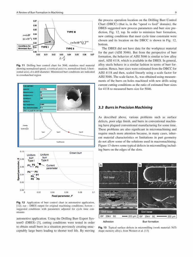
Burr minimization and prevention in drilling is stronglyrelated to process conditions (feedrate and speed, for exam-ple) and drill geometry. It is possible to represent the reason-able ranges of operating conditions for drilling by use of a“burr control chart” derived from experimental data on burrformation for varying speeds and feeds. This can be normal-ized to cover a range of drill diameters and, importantly, canbe used across similar materials (carbon steels, for example).Data shows the likelihood of creating one of three standardburrs, as shown in Fig. 3, namely, small uniform (Type I),large uniform (Type II) and crown burr (Type III). Figure 11below shows a typical burr control chart for 304L stainlesssteel. Continuous lines delineate different burr types. Type Iis preferred. Burr height scales with distance from the ori-gin. This burr control chart can be integrated with an expertsystem allowing queries of likelihood of burr formation to beshown on the control chart when information on drill diam-eter, speed, feed, etc. are input. Typical burr sizes expectedare shown.
An interesting example applying this burr controlapproach was described by Min and Dornfeld [12] for an
A Review of Burr Formation in Machining 9
Fig. 11 Drilling burr control chart for 304L stainless steel materialshowing normalized speed, s (vertical axis) vs. normalized feed, f (hori-zontal axis), d is drill diameter. Minimized burr conditions are indicatedin crosshatched region
Fig. 12 Application of burr control chart in automotive application,[12]; top – DBES output for original machining conditions; bottom –suggested conditions with parameters adjusted for cycle time con-straints
automotive application. Using the Drilling Burr Expert Sys-tem© (DBES) [3], cutting conditions were tested in orderto obtain small burrs in a situation previously creating unac-ceptably large burrs leading to shorter tool life. By moving
the process operation location on the Drilling Burr ControlChart (DBCC) (that is, in the “speed vs feed” domain), theDBES suggested new process parameters and burr size pre-diction, Fig. 12, top. In order to minimize burr formation,new cutting conditions that meet cycle time constraint werechosen and its location on the DBCC is shown in Fig. 12,bottom.
The DBES did not have data for the workpiece materialfor the part (AISI 5046). But from the perspective of burrformation, the behavior of AISI 5046 is similar to low alloysteel, AISI 4118, which is available in the DBES. In general,alloy steels behave in a similar fashion in terms of burr for-mation. Hence, burr sizes were estimated from the DBCC forAISI 4118 and then, scaled linearly using a scale factor forAISI 5046. The scale factor, Sf, was obtained using measure-ments of the burrs on holes machined with new drills usingcurrent cutting conditions as the ratio of estimated burr sizesfor 4118 to measured burrs size for 5046.
3.3 Burrs in Precision Machining
As described above, various problems such as surfacedefects, poor edge finish, and burrs in conventional machin-ing have plagued conventional manufacturing for some time.These problems are also significant in micromachining andrequire much more attention because, in many cases, inher-ent material characteristics or limitations in part geometrydo not allow some of the solutions used in macromachining.Figure 13 shows some typical defects in micromilling includ-ing burrs on the edges of the slots.
Fig. 13 Typical surface defects in micromilling (work material: NiTishape memory alloy), from Weinert et al. [13]

10 D. Dornfeld and S. Min
NiTi work material is used for many medical applications,such as surgical implants, and micromilling is commonlyused to fabricate these products. This material is very ductileand easily work hardens during machining causing adhesionand high burr formation. Additionally, high ductility causesadverse chip formation, long and continuously snarled chips.At the micro level, these chips interfere with tool engagementand burrs and contribute to poor surface quality of finishedparts.
As part of a study on the burr formation in microma-chining Lee and Dornfeld [14] conducted micro-slot millingexperiments on aluminum and copper and found variousstandard burr types depending on location and work geom-etry. Interestingly, these burr shapes were similar to thosefound in macromachining in terms of formation mechanismsand influence of cutting parameters. One major differencefound was that the influence of tool run-out on burr forma-tion was significant in micro-slot milling.
Min et al. [15] conducted micro-fly cutting and micro-drilling experiments on single crystal and polycrystallineOFHC copper in order to understand the effects of crystalorientation, cutting speed, and grain boundaries on surfaceroughness, chip formation, and burr formation. Certain crys-tallographic orientations were found to yield rougher surfacefinish, as well as significant burrs and breakout at the toolexit edge. The <100> and <110> direction of machining onthe workpieces exhibited the greatest amount of variationin formation of burrs and breakout at the exit edge and inchip topology as a function of the angular orientation of theworkpiece. This corresponded to a variation in the interac-tion between the tool and the active slip systems. They alsoconducted slot milling experiments on the same material andfound a strong dependency of top burr formation on slip sys-tems of each crystal orientation except (100) workpiece.
Bissacco et al. [16] found that top burrs are relatively largein micromilling due to the size effect. When the ratio of thedepth of cut to the cutting edge radius is small, high biax-ial compressive stress pushes material toward the free sur-face and generates large top burrs. Ahn and Lim [17], Ahnet al. [8] proposed a burr formation model in a microgroov-ing operation based on a side shear plane and an extendeddeformation area which is caused by the tool edge radiuseffect. The material near the cutting edge experiences theside shear deformation due to hydrostatic pressure. Alu-minum and OFHC generated larger burrs than brass, and thusit was concluded that the thickness of the burr is proportionalto the ductility of the material.
Further work by Schaller et al. [19] showed that when fab-ricating microgrooves in brass, burr formation can be drasti-cally reduced by coating the surface with cyanacrylate. Sug-awara and Inagaki [20] investigated the effect of drill diame-ter and crystal structure on burr formation in microdrilling.They utilized both single crystal and polycrystalline iron
(a) 10 mm/min, 7000 rpm (b) 5 mm/min, 6000 rpm
(c) 5 mm/min, 7000 rpm (d) 10 mm/min, 8000 rpm
Fig. 14 Microdrilling burr formation (250 μm diameter); (a) burrwithin grain boundary, (b) burr across grain boundary, (c) burr oversmall grain, (d) grain boundary follows burr topology, from Min et al.[15]
with a thickness between 0.06 and 2.5 mm and high speedtwist drills with diameters from 0.06 to 2.5 mm. In generalthey confirmed that burr size is reduced and cutting abilityincreased as drill size decreases.
Min et al. [15] found that grain orientation affected burrformation in drilling of polycrystalline copper, Fig. 14. A sin-gle material may produce a ductile-like cutting mode in onegrain and brittle-like cutting in another, indicating that favor-able and non-favorable cutting orientations for good surfaceand edge condition exist as a function of crystallographic ori-entation.
Additional micro-drilling research indicated that theeffects seen at a larger, macro, scale (transition from uni-form to crown burr with feed increase and basic similarityin burr shapes) also holds for microdrilling [21]. This meansthe drilling burr control chart concept could be applied at thisscale also.
4 Summary and Conclusions
Although edge finishing in machined components is a con-stant challenge in precision manufacturing of mechanicalcomponents, there are a number of strategies, built on com-petent process models and extensive data bases, that can sub-stantially minimize or eliminate burrs. These strategies, someillustrated above, can be incorporated in the software relied