Burn-In FINAL
28
Burn-In Danny Ventura Rafal Piersiak June 8 – August 14, 2015
-
Upload
danny-ventura -
Category
Documents
-
view
18 -
download
0
Transcript of Burn-In FINAL

Burn-In Danny Ventura
Rafal Piersiak
June 8 – August 14, 2015

What is purpose of Burn-In?
• Burn-In is a reliability test in which a device is switched on and exercised at peak performance for a long time.
• Purpose of Thync Burn-In Board-• To test Thync module reliability
• Reduce testing cost/ unit
• Vastly increase production

Stages of Project
• Test/improve current waveform capture circuit on FT1 PCB
• Research system architecture
• Schematic capture
• Placement and layout
• Mechanical design and integration

Waveform Capture
• Input wave (yellow) and Output ADC (pink)
• With Diff Amplifier

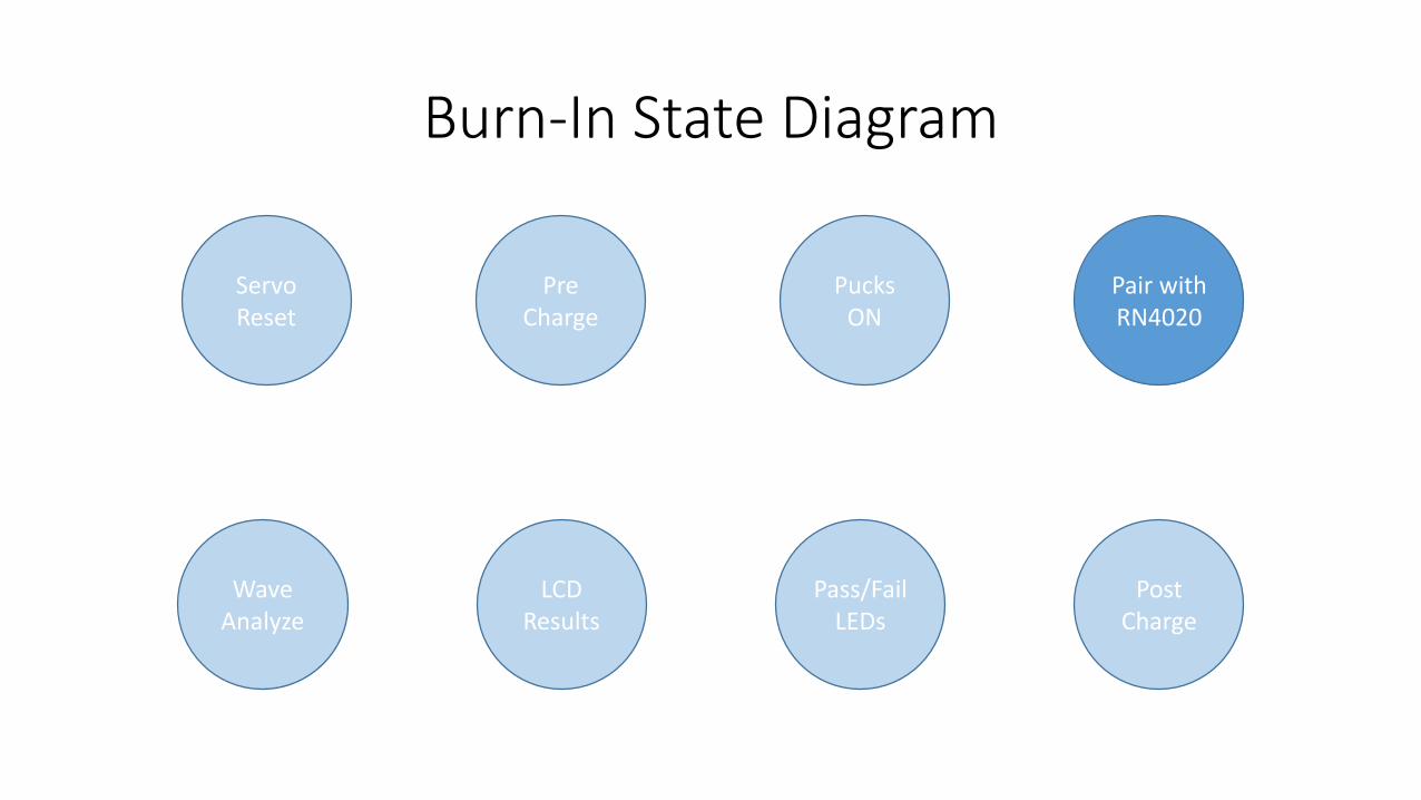
Burn-In State Diagram
Servo Reset
Pre Charge
Pucks ON
Pair with RN4020
Wave Analyze
LCD Results
Pass/Fail LEDs
Post Charge

Burn-In State Diagram
Servo Reset
Pre Charge
Pucks ON
Pair with RN4020
Wave Analyze
LCD Results
Pass/Fail LEDs
Post Charge

Burn-In State Diagram
Servo Reset
Pre Charge
Pucks ON
Pair with RN4020
Wave Analyze
LCD Results
Pass/Fail LEDs
Post Charge
Burn-In State Diagram
Servo Reset
Pre Charge
Pucks ON
Pair with RN4020
Wave Analyze
LCD Results
Pass/Fail LEDs
Post Charge

Burn-In State Diagram
Servo Reset
Pre Charge
Pucks ON
Pair with RN4020
Wave Analyze
LCD Results
Pass/Fail LEDs
Post Charge

Burn-In State Diagram
Servo Reset
Pre Charge
Pucks ON
Pair with RN4020
Wave Analyze
LCD Results
Pass/Fail LEDs
Post Charge

Burn-In State Diagram
Servo Reset
Pre Charge
Pucks ON
Pair with RN4020
Wave Analyze
LCD Results
Pass/Fail LEDs
Post Charge

Burn-In State Diagram
Servo Reset
Pre Charge
Pucks ON
Pair with RN4020
Wave Analyze
LCD Results
Pass/Fail LEDs
Post Charge

Heart of the Board
• Peripherals• Switch
• Buzzer
• LEDs
• Servos
• FTDI
• ADCs
• BLE RN4020
• LCD
• USB Charging
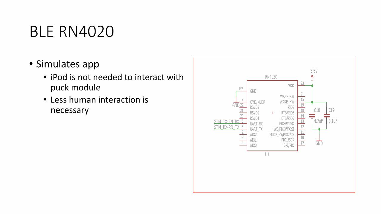
BLE RN4020
• Simulates app• iPod is not needed to interact with
puck module
• Less human interaction is necessary

Waveform Capture Circuit
• Steps-down Puck’s 60V to 4V
• Probe A & B
• Diff amplifier smoothens output signal

USB Charging
• Circuit regulates 9V to 5V
• Monitors current

Board layout
STM32

Board layout
RN4020

Board layout
WaveformCapture

Board layout
USB Chargers

3d –Printing Fixtures

Current Set-up
• Current Flextronics set-up
• One oscilloscope is used to test one puck.
• 1 out of 4 channels in use
• $400 equipment only tests one puck
• Limited bandwidth
• Area used is 12 x 13 in.

Future Set-up
• LCD in front of stadium
• Puck and Servo fixtures
• Measures 10 x 12 in.

Current Vs. Future
4 Modules/Area 32 Modules/Area

Cost
Table includes equipment cost for testing 8 Thync modules
Current Setup Cost
Oscilloscope/Phantom $3240
Operator Time (11.68 minutes) $4.86
New Setup Cost
Test Fixture/PCB $665
Operator Time (1.10 minutes) $0.45
79% Cost Reduction for Equipment90% Cost Reduction for Operator Time

Benefits
• Cheaper per module to test and operate.
• Automates pre-charge, burn-in, and post-charge.
• Scalable
• Human operation is minimized to snapping module and push button.
• Reduces human handling.
• Smaller fixture uses less space.
• Tuned waveform capture, specific to custom designed burn-in waveform.

Team Effort
• Rafal guided
• Jay revised layout and schematic revisions
• Remi aided with circuit design of the WFC and differential amplifier
• Uma leads software that will be used with board
• Matt solved issues with RN4020
• Thanks to Hardware Team for individual input in project or guidance.

Conclusion
• Questions or comments?