Burgin Independent Schools Bathroom Renovation
450
Burgin Independent Schools Bathroom Renovation Burgin Independent Board of Education Burgin, Kentucky RTA 1809 BG 18-290 Project Manual - April 2018 Architect RossTarrant Architects, Inc. p 859.254.4018 Mechanical & Electrical Engineer Staggs & Fisher Consulting Engineers p 859.271.3246
Transcript of Burgin Independent Schools Bathroom Renovation

Burgin Independent Schools Bathroom Renovation
Burgin Independent Board of Education Burgin, Kentucky
RTA 1809 BG 18-290
Project Manual -
April 2018
Architect RossTarrant Architects, Inc.
p 859.254.4018
Mechanical & Electrical Engineer Staggs & Fisher Consulting Engineers
p 859.271.3246

RTA 1809
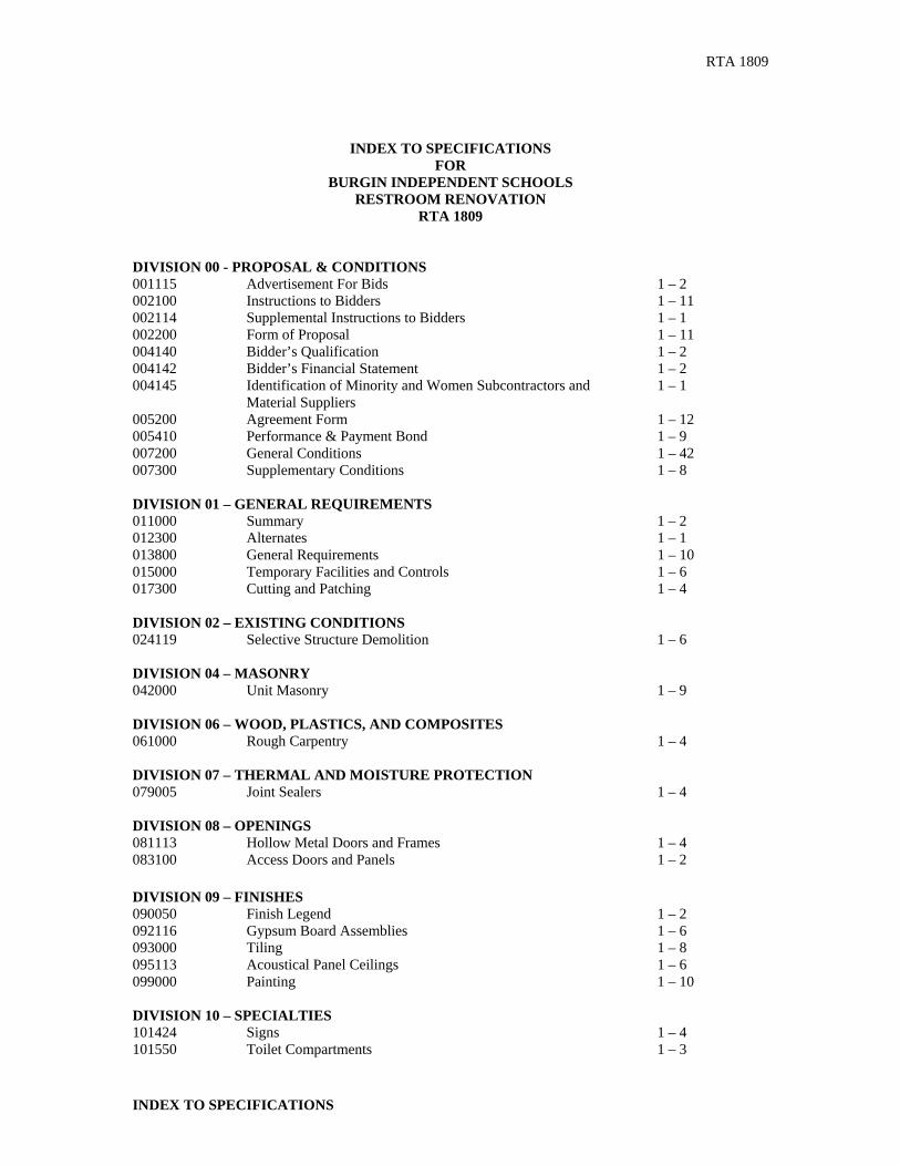
INDEX TO SPECIFICATIONS
INDEX TO SPECIFICATIONS FOR
BURGIN INDEPENDENT SCHOOLS RESTROOM RENOVATION
RTA 1809
DIVISION 00 - PROPOSAL & CONDITIONS 001115 Advertisement For Bids 1 – 2 002100 Instructions to Bidders 1 – 11 002114 Supplemental Instructions to Bidders 1 – 1 002200 Form of Proposal 1 – 11 004140 Bidder’s Qualification 1 – 2 004142 Bidder’s Financial Statement 1 – 2 004145 Identification of Minority and Women Subcontractors and
Material Suppliers 1 – 1
005200 Agreement Form 1 – 12 005410 Performance & Payment Bond 1 – 9 007200 General Conditions 1 – 42 007300 Supplementary Conditions 1 – 8 DIVISION 01 – GENERAL REQUIREMENTS 011000 Summary 1 – 2 012300 Alternates 1 – 1 013800 General Requirements 1 – 10 015000 Temporary Facilities and Controls 1 – 6 017300 Cutting and Patching 1 – 4 DIVISION 02 – EXISTING CONDITIONS 024119 Selective Structure Demolition 1 – 6 DIVISION 04 – MASONRY 042000 Unit Masonry 1 – 9 DIVISION 06 – WOOD, PLASTICS, AND COMPOSITES 061000 Rough Carpentry 1 – 4 DIVISION 07 – THERMAL AND MOISTURE PROTECTION 079005 Joint Sealers 1 – 4 DIVISION 08 – OPENINGS 081113 Hollow Metal Doors and Frames 1 – 4 083100 Access Doors and Panels 1 – 2 DIVISION 09 – FINISHES 090050 Finish Legend 1 – 2 092116 Gypsum Board Assemblies 1 – 6 093000 Tiling 1 – 8 095113 Acoustical Panel Ceilings 1 – 6 099000 Painting 1 – 10 DIVISION 10 – SPECIALTIES 101424 Signs 1 – 4 101550 Toilet Compartments 1 – 3


RTA 1809
INDEX TO SPECIFICATIONS
102800 Toilet and Bath Accessories 1 – 4 DIVISION 22 – PLUMBING 220000 General Provisions for Plumbing 1 – 14 220500 Common Work Results for Plumbing 1 – 11 220517 Sleeves and Sleeve Seals for Plumbing Piping 1 – 5 220518 Escutcheons for Plumbing Piping 1 – 3 220523 General-Duty Valves for Plumbing Piping 1 – 5 220529 Hangers and Supports for Plumbing and Equipment 1 – 9 220553 Identification for Plumbing Piping and Equipment 1 – 6 220719 Plumbing Piping Insulation 1 – 18 221116 Domestic Water Piping 1 – 12 221316 Sanitary Waste and Vent Piping 1 – 12 224000 Plumbing Fixtures 1 – 7
DIVISION 23 – HVAC 230000 General Provisions for HVAC Systems 1 – 17 230513 Common Motor Requirements for HVAC Equipment 1 – 3 230529 Hangers and Supports for HVAC Piping and Equipment 1 – 8 230553 Identification for HVAC Piping and Equipment 1 – 6 230593 Testing Adjusting and Balancing for HVAC 1 – 5 230713 Duct Insulation 1 – 14 233113 Metal Ducts 1 – 10 233423 HVAC Power Ventilators 1 – 5 DIVISION 26 – ELECTRICAL 260000 General Electrical Provisions 1 – 10 260411 Selective Demolition 1 – 6 260500 Common Work Results for Electrical 1 – 4 260519 Low-Voltage Electrical Power Conductors and Cables 1 – 3 260526 Grounding and Bonding for Electrical Systems 1 – 2 260529 Hangers and Supports for Electrical Systems 1 – 3 260533 Raceway and Boxes for Electrical Systems 1 – 5 262726 Wiring Devices 1 – 7 265119 LED Interior Lighting 1 – 4 DIVISION 28 – ELECTRONIC SAFETY & SECURITY 280500 Common Work Results for Electronic Safety and Security 1 – 5 END OF INDEX TO SPECIFICATIONS


RTA 1809
ADVERTISEMENT FOR BIDS 001115 - 1
SECTION 001115 - ADVERTISEMENT FOR BIDS
Sealed proposals for the following work will be received by the Burgin Independent Board ofEducation in the manner and on the date hereinafter specified for the furnishing of all labor, materials,supplies, tools, equipment, services, etc., necessary for the construction of the Burgin IndependentSchools Bathroom Renovation as set forth in the specifications and as shown on the drawings preparedby RossTarrant Architects, Inc., 101 Old Lafayette Avenue, Lexington, Kentucky 40502.
Bid Submittal: Contractors must submit their bids to the Burgin Independent Board of Education, 440East Main Street, Burgin, Kentucky 40310 until: May 22, 2018, 11:00 am, local time.
Each Proposal shall be submitted on forms contained in the Project Manual. Proposals shall beenclosed in a sealed envelope with the following information on the outside:
Sealed Bid for the:
Burgin Independent Schools Bathroom Renovation
No proposal shall be withdrawn for a period of sixty (60) days after the date of bid opening.
Pre-Bid Conference: A pre-bid conference will be held on May 8, 2018 at 10:00 am local time, at theproject site. Each bidder is encouraged to visit the site to review field conditions prior to submitting abid.
Addenda: The last date for the Architect to receive items to be addressed in any addenda is May 15,2018 by 12:00 p.m. EDT. All requests must be submitted to the Architect in writing.
Method of Receiving Bids: Bids will be received from Contractors for a Total Lump Sum Amount. All phases of the work shall be bid to and through the Contractor submitting the proposal. BidSecurity in the amount of five (5) percent of each proposal submitted must accompany each Proposalin accordance with the Form of Proposal.
Right to Reject and Waiver: The Owner reserves the right to accept any bid, to reject any or all bids,to waive any informalities in bids received where such acceptance, rejection, or waiver is consideredto be in the best interest of the Owner or to reject any bid where evidence or information submitted bythe bidder does not satisfy the Owner that the bidder is qualified to carry out the details of the ContractDocuments. The Owner's desire to waive irregularities and informalities as to a bid shall be reviewedand final judgement made by the Kentucky Department of Education, Division of FacilitiesManagement, prior to approval of the contract and financing plan.
Plans and Specifications Reviewed: Contract Documents may be examined at the following places:Burgin Independent Board of Education, 440 East Main Street, Burgin, Kentucky 40310Staggs & Fisher, Inc., 3264 Lochness Drive, Lexington, Kentucky 40517
Obtaining Plans and Specifications: Bidders may obtain contract documents from Lynn Imaging, 328Old East Vine Street, Lexington, Kentucky 40507 (telephone (859) 255-1021), in accordance with thefollowing deposit and charge schedule.
First and Second Set $50.00 Per SetRefundable
Additional Sets $50.00 Per SetNon-Refundable
Postage and handling fees shall be paid directly to Lynn Imaging. Deposit checks shall be madepayable to RossTarrant Architects, Inc. It is most important that requesting firm identify the positionof the firm as to prime bidder, miscellaneous Contractor, material supplier, or other. Please givename, address, telephone number and email address of person responsible for receiving Addendamaterial and general communication concerning this bidding.

RTA 1809
ADVERTISEMENT FOR BIDS 001115 - 2
Plans and Specifications must be returned directly to Lynn Imaging within thirty (30) calendar daysafter the closing date for the receipt of bids, in good condition, otherwise no refund will be made.
General Information: State Wage Rates are not applicable. Conflicts of interest, gratuities andkickbacks are defined in KRS 45A.445 and as provided for in KRS 45A.455 are absolutely prohibited. Preference for resident bidders shall be given as outlined in KRS 45A.90 to 45A.94. The successfulbidder must supply a 100% Performance and Payment Bond as outlined in the Project Manual.
Project Location: Burgin Independent Schools, 440 East Main Street, Burgin, Kentucky 40310.
Project Description: The scope of work for the base bid includes the renovation of one boys' and onegirls' gang toilets located on the first floor of the building. Work includes new plumbing fixtures andnew finishes.
END OF SECTION

RTA 1809
INSTRUCTIONS TO BIDDERS 002100 - 1
SECTION 002100 - INSTRUCTIONS TO BIDDERS
PART 1 GENERAL
1.01 Refer to the Kentucky Department of Education Version of AIA Document A701-1997.END OF SECTION


RTA 1809
SUPPLEMENTAL INSTRUCTIONS TO BIDDERS 002114 - 1
SECTION 002114 - SUPPLEMENTAL INSTRUCTIONS TO BIDDERS
SCOPE
The following Supplemental Instructions to Bidders modify, change, delete from, or add to AIA DocumentA701-1997 "Instructions to Bidders", Kentucky Department of Education version, which is included herein asa part of the Contract Documents.
ARTICLE 3 - BIDDING DOCUMENTS
Add the following:
3.5 Bids will be received from Contractors for a total lump sum amount. All phases of the work shallbe bid to and through the Contractor submitting the proposal.
ARTICLE 4 - BIDDING PROCEDURES
Add to Paragraph 4.3.1:
4.3.1.1 The bidder shall submit the following documents at the time of the bid opening:Form of Proposal (KDE Document) - Submit one original.Bid Security - Submit one original.
4.3.1.2 The bidder shall submit the following documents within 1 hour of the bid opening:Form of Proposal Pages 4 & 5: List of Proposed Suppliers and Manufacturers. An electroniccopy is acceptable.Form of Proposal Pages 6 & 7: Unit Prices. An electronic copy is acceptable.
4.3.1.3 The bidder shall submit the following documents within 24 hours of the bid opening:Form of Proposal Section 004140: Bidder's Qualifications - Submit one completed formwithin 24 hours of the bid opening. An electronic copy is acceptable.
4.3.1.4 The bidder shall submit the following documents within 48 hours of the bid opening:Form of Proposal Section 004145: Identification of Minority and Women Subcontractorsand Material Suppliers. An electronic copy is acceptable.
4.3.1.5 The apparent successful bidder may be asked to submit the following document within 24hours of the bid opening:
Form of Proposal Section 004142: Bidder's Financial Statement - Submit one completedform within 24 hours of the bid opening if requested. An electronic copy is acceptable.
ARTICLE 6 - POST-BID INFORMATION
Add the following paragraphs:
6.3.5 In determining the qualifications of the bidder with regard to the bidder's experience, the bidderis expected to be able to show experience which reflects a similar or equivalent scale, scope andcomplexity to the project. Qualifying bidders should expect to be able to provide the following:
6.3.5.1 Project experience of at least ten projects with a similar type of construction, directlyrelated to educational function, if possible, within the last five years.
ARTICLE 9 - PUBLIC WORKS ACT (REFERENCE KRS 337.550)
Delete Article 9.1 Labor Regulations in its entirety. Kentucky prevailing wage rates will not apply to thisproject.
Delete Article 9.2 David-Bacon Act Provisions in its entirety. Federal prevailing wage rates will not apply tothis project.
END OF SECTION


KENTUCKY DEPARTMENT OF EDUCATION FORM OF PROPOSAL 702 KAR 4:160
Form of Proposal – 2013 Page 1 of 11 BG #18-290
BG No. 18-290 Date: ____________________________ To: (Owner) Burgin Independent Board of Education
Project Name: Burgin Independent Schools Bathroom Renovation Bid Package: NA (GC)
City, County: Burgin, Mercer County, Kentucky
Name of Contractor: _______________________________________________________________________________
Mailing Address: _________________________________________________________________________________
Business Address: _________________________________________________Telephone:_____________________
Having carefully examined the Instructions to Bidders, Contract Agreement, General Conditions, Supplemental Conditions, Specifications, and Drawings, for the above referenced project, the undersigned bidder proposes to furnish all labor, materials, equipment, tools, supplies, and temporary devices required to complete the work in accordance with the contract documents and any addenda listed below for the price stated herein. Addendum _____________________ (Insert the addendum numbers received or the word "none" if no addendum
received.) BASE BID: For the construction required to complete the work, in accordance with the contract documents, I/We submit the following lump sum price of: _____________________________________ Use Figures __________________________________________________ Dollars & _________________________________Cents Use Words Use Words ALTERNATE BIDS: (If applicable and denoted in the Bidding Documents) For omission from or addition to those items, services, or construction specified in Bidding Documents by alternate number, the following lump sum price will be added or deducted from the base bid.
Alternate Bid No. Alternate Description + (Add to the Base Bid) - (Deduct from the Base Bid) No Cost Change
from the Base Bid)
Alt. Bid No. 1 Second Floor Toilet Renovations
Alt. Bid No. 2 First Floor Ceramic Wall Tile
Alt. Bid No. 3 Second Floor Ceramic Wall Tile
Alt. Bid No. 4
Alt. Bid No. 5
Alt. Bid No. 6
Alt. Bid No. 7 Alt. Bid No. 8 Alt. Bid No. 9
Alt. Bid No. 10
A maximum of 10 Alternate Bids will be acceptable with each Base Bid. Do not add supplemental sheets for Alternate Bids to this document.

KENTUCKY DEPARTMENT OF EDUCATION FORM OF PROPOSAL 702 KAR 4:160
Form of Proposal – 2013 Page 2 of 11 BG #18-290
LIST OF PROPOSED SUBCONTRACTORS: List on the lines below each major branch of work and the subcontractor involved with that portion of work. If the branch of work is to be done by the Contractor, so indicate. The listing of more than one subcontractor in a work category shall invalidate the bid. The listing of the bidder as the subcontractor for a work category certifies that the bidder has in current employment, skilled staff and necessary equipment to complete that category. The architect/engineer will evaluate the ability of all listed subcontractors to complete the work and notify the owner. Listing of the bidder as the subcontractor may invalidate the bid should the architect's review indicate bidder does not have skilled staff and equipment to complete the work category at the time the bid was submitted. A maximum of 40 subcontractors will be acceptable with each bid. Do not add supplemental sheets for subcontractors to this document.
The bidder shall submit the list of subcontractors with the bid.
BRANCH OF WORK (to be filled out by the Architect)
SUBCONTRACTOR (to be filled out by the contractor)
1. Plumbing
2. Sheet Metal
3. Test and Balance
4. Electrical
5. CMU
6. Ceramic Tile
7.
8.
9.
10.
11.
12.
13.
14.
15.
16.
17.

KENTUCKY DEPARTMENT OF EDUCATION FORM OF PROPOSAL 702 KAR 4:160
Form of Proposal – 2013 Page 3 of 11 BG #18-290
BRANCH OF WORK (to be filled out by the Architect)
SUBCONTRACTOR (to be filled out by the contractor)
18.
19.
20.
21.
22.
23.
24.
25.
26.
27.
28.
29.
30.
31.
32.
33.
34.
35.
36.
37.
38.
39.
40.

KENTUCKY DEPARTMENT OF EDUCATION FORM OF PROPOSAL 702 KAR 4:160
Form of Proposal – 2013 Page 4 of 11 BG #18-290
LIST OF PROPOSED SUPPLIERS AND MANUFACTURERS: List on the lines below each major material category for this project and the suppliers and manufacturers involved with that portion of work. Listing the supplier below means the Contractor is acknowledging authorization from the Supplier to include the Supplier in this bid.
The listing of more than one supplier or manufacturer in a material category shall invalidate the bid. A maximum of 40 suppliers and manufacturers will be acceptable with each bid. Do not add supplemental sheets for suppliers to this document. The bidder shall submit the list of suppliers and manufacturers within one (1) hour of the bid. MATERIAL DESCRIPTION BY
SPECIFICATION DIVISION AND CATEGORY
(to be filled out by the Architect or Contractor)
SUPPLIER (to be filled out by the Contractor)
MANUFACTURER (to be filled out by the Contractor)
1. Water Closet
2. Urinal
3. Lavatory
4. Mop Basin
5. Water Hammer Arrestor
6. Exhaust Fan
7. Wiring Devices
8. Lighting Fixture Types (Attach List)
9. Valves and Accessories
10. Flush Valves
11. Insulation
12. Louvers
13.
14.
15.
16.
17.
18.

KENTUCKY DEPARTMENT OF EDUCATION FORM OF PROPOSAL 702 KAR 4:160
Form of Proposal – 2013 Page 5 of 11 BG #18-290
MATERIAL DESCRIPTION BY SPECIFICATION DIVISION AND
CATEGORY (to be filled out by the Architect or Contractor)
SUPPLIER (to be filled out by the Contractor)
MANUFACTURER (to be filled out by the Contractor)
19.
20.
21.
22.
23.
24.
25.
26.
27.
28.
29.
30.
31.
32.
33.
34.
35.
36.
37.
38.
39.
40.

KENTUCKY DEPARTMENT OF EDUCATION FORM OF PROPOSAL 702 KAR 4:160
Form of Proposal – 2013 Page 6 of 11 BG #18-290
UNIT PRICES: Indicate on the lines below those unit prices to determine any adjustment to the contract price due to changes in work or extra work performed under this contract. The unit prices shall include the furnishing of all labor and materials, cost of all items, and overhead and profit for the Contractor, as well as any subcontractor involved. These unit prices shall be listed in units of work. A maximum of 40 unit prices will be acceptable with each bid. Do not add supplemental sheets for unit pricing to this document. The bidder shall submit the list of unit prices within one (1) hour of the bid. WORK
(to be filled out by the Architect)
PRICE / UNIT (to be filled out by the Contractor)
UNIT (to be filled out by the
Contractor)
16” CMU wall in-place
/SF
21” Aramaflex 25/50 flame/smoke
/LF
3 Duplex wall receptacle with 25' of conduit/wiring with connection to circuit
/EA
4 GFI receptacle with 25' of conduit/wiring with connection to circuit
/EA
5"LF-1" Light Fixture
/EA
6"LF-1A" Light Fixture
/EA
7 Exhaust fan w/ ECM high efficiency motor (see schedule)
/EA
8 Exhaust fan w/ standard motor (direct drive, 120v/1ph)
/EA
9Ceramic wall tile, installed
/SF
10
11
12
13
14
15
16
17
18
19

KENTUCKY DEPARTMENT OF EDUCATION FORM OF PROPOSAL 702 KAR 4:160
Form of Proposal – 2013 Page 7 of 11 BG #18-290
WORK (to be filled out by the Architect)
PRICE / UNIT (to be filled out by the Contractor)
UNIT (to be filled out by the
Contractor)
20
21
22
23
24
25
26
27
28
29
30
31
32
33
34
35
36
37
38
39
40

KENTUCKY DEPARTMENT OF EDUCATION FORM OF PROPOSAL 702 KAR 4:160
Form of Proposal – 2013 Page 8 of 11 BG #18-290
DIRECT MATERIAL PURCHASES: Indicate on the lines below those materials to be purchased directly by the Owner with a Purchase Order to be issued by the Owner to the individual suppliers. The value of the direct Purchase Order cannot be less than $5,000. Following the approval of bids, the Contractor shall formalize this list by completing and submitting the electronic Purchase Order Summary Form provided by KDE. Listing the supplier below means the Contractor is acknowledging authorization from the Supplier to include the Supplier in this bid. A maximum of 50 POs will be acceptable with each bid. Do not add supplemental sheets for additional POs to this document. The bidder shall submit the list of Purchase Orders within four (4) days of the bid. SUPPLIER
(to be filled out by the Contractor)
PURCHASE ORDER DESCRIPTION (to be filled out by the Contractor)
PURCHASE ORDER AMT. (to be filled out by the Contractor)
1. NA NA NA
2. NA NA NA
3. NA NA NA
4. NA NA NA
5. NA NA NA
6. NA NA NA
7. NA NA NA
8. NA NA NA
9. NA NA NA
10. NA NA NA
11. NA NA NA
12. NA NA NA
13. NA NA NA
14. NA NA NA
15. NA NA NA
16. NA NA NA
17. NA NA NA
18. NA NA NA
19. NA NA NA

KENTUCKY DEPARTMENT OF EDUCATION FORM OF PROPOSAL 702 KAR 4:160
Form of Proposal – 2013 Page 9 of 11 BG #18-290
SUPPLIER (to be filled out by the Contractor)
PURCHASE ORDER DESCRIPTION (to be filled out by the Contractor)
PURCHASE ORDER AMT. (to be filled out by the Contractor)
20. NA NA NA
21. NA NA NA
22. NA NA NA
23. NA NA NA
24. NA NA NA
25. NA NA NA
26. NA NA NA
27. NA NA NA
28. NA NA NA
29. NA NA NA
30. NA NA NA
31. NA NA NA
32. NA NA NA
33. NA NA NA
34. NA NA NA
35. NA NA NA
36. NA NA NA
37. NA NA NA
38. NA NA NA
39. NA NA NA
40. NA NA NA
41. NA NA NA
42. NA NA NA
43. NA NA NA
44. NA NA NA

KENTUCKY DEPARTMENT OF EDUCATION FORM OF PROPOSAL 702 KAR 4:160
Form of Proposal – 2013 Page 10 of 11 BG #18-290
SUPPLIER (to be filled out by the Contractor)
PURCHASE ORDER DESCRIPTION (to be filled out by the Contractor)
PURCHASE ORDER AMT. (to be filled out by the Contractor)
45. NA NA NA
46. NA NA NA
47. NA NA NA
48. NA NA NA
49. NA NA NA
50. NA NA NA
KENTUCKY DEPARTMENT OF EDUCATION FORM OF PROPOSAL 702 KAR 4:160
Form of Proposal – 2013 Page 11 of 11 BG #18-290
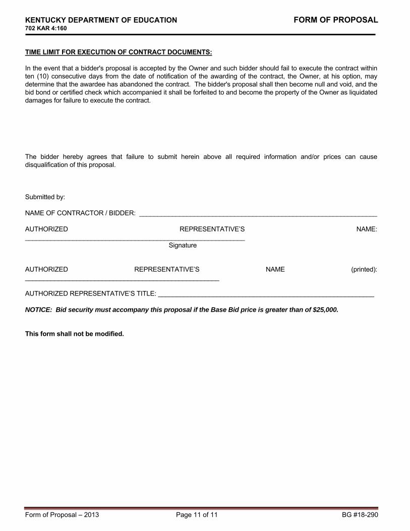
TIME LIMIT FOR EXECUTION OF CONTRACT DOCUMENTS: In the event that a bidder's proposal is accepted by the Owner and such bidder should fail to execute the contract within ten (10) consecutive days from the date of notification of the awarding of the contract, the Owner, at his option, may determine that the awardee has abandoned the contract. The bidder's proposal shall then become null and void, and the bid bond or certified check which accompanied it shall be forfeited to and become the property of the Owner as liquidated damages for failure to execute the contract. The bidder hereby agrees that failure to submit herein above all required information and/or prices can cause disqualification of this proposal. Submitted by: NAME OF CONTRACTOR / BIDDER: _________________________________________________________________ AUTHORIZED REPRESENTATIVE’S NAME: ____________________________________________________________ Signature AUTHORIZED REPRESENTATIVE’S NAME (printed): _____________________________________________________ AUTHORIZED REPRESENTATIVE’S TITLE: ___________________________________________________________ NOTICE: Bid security must accompany this proposal if the Base Bid price is greater than of $25,000. This form shall not be modified.

RTA 1809
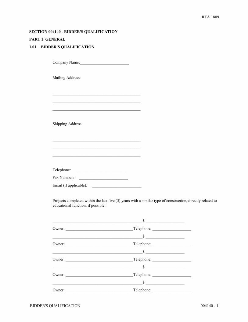
BIDDER'S QUALIFICATION 004140 - 1
SECTION 004140 - BIDDER'S QUALIFICATION
PART 1 GENERAL
1.01 BIDDER'S QUALIFICATION
Company Name:________________________
Mailing Address:
___________________________________________
___________________________________________
___________________________________________
Shipping Address:
___________________________________________
___________________________________________
___________________________________________
Telephone: ________________________
Fax Number: ________________________
Email (if applicable): ________________________
Projects completed within the last five (5) years with a similar type of construction, directly related toeducational function, if possible:
____________________________________________$ ___________________
Owner: _________________________________Telephone: ___________________
____________________________________________$ ___________________
Owner: _________________________________Telephone: ___________________
____________________________________________$ ___________________
Owner: _________________________________Telephone: ___________________
____________________________________________$ ___________________
Owner: _________________________________Telephone: ___________________
____________________________________________$ ___________________
Owner: _________________________________Telephone: ___________________
RTA 1809
BIDDER'S QUALIFICATION 004140 - 2
We now have the following jobs under contract and bonded:
____________________________________________$ ___________________
____________________________________________$ ___________________
____________________________________________$ ___________________
____________________________________________$ ___________________
____________________________________________$ ___________________
____________________________________________$ ___________________
____________________________________________$ ___________________
____________________________________________$ ___________________
Personnel: The superintendent on site for the project is scheduled to be:
____________________________________________.
The project manager in the office for the project is scheduled to be:
____________________________________________.END OF SECTION

RTA 1809
BIDDER'S FINANCIAL STATEMENT 004142 - 1
SECTION 004142 - BIDDER'S FINANCIAL STATEMENT
PART 1 GENERAL
1.01 BIDDER'S QUALIFICATIONS
The Bidder's Qualifications together with the attached affidavit are required by the conditions of theInvitation to be executed and submitted within 24 hours as part of the Proposal if requested.
A. A permanent place of business is maintained at: ___________________________________________
_______________________________________________________________________________
B. The following construction Plant and Equipment will be made available for use of this Contract:
_______________________________________________________________________________
_______________________________________________________________________________
C. Adequate finances are possessed as indicated: (Note: A prepared Company certified financialstatement may be substituted in lieu of the following.)
Conditions at close of business__________________________________, 20_____________
1.02 ASSETS
A. Cash in bank and on hand $__________________
B. Receivable Notes, Accounts, Money Earned, Interest, Guarantee Loan $__________________
C. Stocks and Bonds $__________________
D. Real Estate, Furniture and Fixtures, and Materials $__________________
E. Equipment (After depreciation) $__________________
F. Other Assets (Name) $__________________
Total Assets: $__________________
1.03 LIABILITIES
A. Payable Notes, Accounts, Interest, Loans $__________________
B. Real Estate Encumbrances $__________________
C. Other Encumbrances (Name) $__________________
D. Reserves $__________________
E. Capital Stock Paid Up (All Classes) $__________________
F. Surplus - Net Worth $__________________
In addition to the foregoing, a complete and detailed certified financial statement will be furnished ifrequired.
In the event the Contract is awarded the undersigned, surety bonds will be furnished by:
___________________________________________________________________________________
(Surety Company)

RTA 1809
BIDDER'S FINANCIALSTATEMENT
004142 - 2
Signed:___________________________________
(Representative of Surety Company)
Agent:___________________________________
Address:___________________________________
___________________________________
END OF SECTION

RTA 1809
IDENTIFICATION OF MINORITY AND WOMENSUBCONTRACTORS AND MATERIAL SUPPLIERS
004145 - 1
SECTION 004145 - IDENTIFICATION OF MINORITY AND WOMEN SUBCONTRACTORS ANDMATERIAL SUPPLIERS
PART 1 GENERAL
1.01 SUBMITTAL DATA
A. The utilization of minority and women subcontractors and material suppliers is encouraged andsupported, whenever possible, on public school projects. The bidder and contractor should make fullefforts to locate minority- and women-owned business persons.
B. The apparent successful bidder shall submit this form, along with required attachments, within 48hours of the Bid Opening.
C. For assistance in identifying subcontractors and material suppliers, bidders may contact the KentuckyOffice for Minority Business Enterprises, mwbe.ky.gov, Phone (502) 564-8099 or the Office of EqualOpportunity, Contract Compliance, finance.ky.gov, Phone (502) 564-2874.
D. Minority and women subcontractors and material suppliers to hold subcontracts on this project:
Company Name City/State CertifiedMWBEYes/NoYes/NoYes/NoYes/NoYes/NoYes/NoYes/NoYes/NoYes/NoYes/No
E. Bidder must attach to this Form of Proposal a list of all minority and women subcontractors andmaterial suppliers contacted in order to prepare a bid.
END OF SECTION


RTA 1809
CONTRACT AGREEMENT FORM 005200 - 1
SECTION 005200 - CONTRACT AGREEMENT FORM
FORM OF GENERAL CONDITIONS
1.01 Refer to Kentucky Department of Education Version of AIA Document A101-2007, Standard Form ofAgreement Between Owner and Contractor.
END OF SECTION


RTA 1809
PERFORMANCE & PAYMENT BOND 005410 - 1
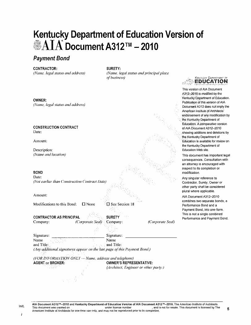
SECTION 005410 - PERFORMANCE & PAYMENT BOND
FORM OF GENERAL CONDITIONS
1.01 Refer to the AIA Document A312, Performance & Payment Bond, 2010END OF SECTION


RTA 1809
GENERAL CONDITIONS 007200 - 1
SECTION 007200 - GENERAL CONDITIONS
FORM OF GENERAL CONDITIONS
1.01 Refer to the Kentucky Department of Education Version of AIA Document A201, General Conditions of theContract for Construction, 2007 Edition.
END OF SECTION


RTA 1809
SUPPLEMENTARY CONDITIONS 007300 - 1
SECTION 007300 - SUPPLEMENTARY CONDITIONS
PART 1 GENERAL
1.01 SUMMARY
A. These Supplementary Conditions amend and supplement the General Conditions defined in Document007200 - General Conditions and other provisions of the Contract Documents as indicated below. Provisions that are not so amended or supplemented remain in full force and effect.
B. The terms used in these Supplementary Conditions that are defined in the General Conditions have themeanings assigned to them in the General Conditions.
1.02 DEFINITIONS
A. The term "OWNER" as used throughout these documents means the Burgin Independent Board ofEducation.
B. The term "ARCHITECT" as used throughout these documents means RossTarrant Architects, Inc.,101 Old Lafayette Avenue, Lexington, Kentucky 40502.
C. The terms "PLANS" and "DRAWINGS" are used interchangeably and are construed to have the samemeaning.
1.03 GENERAL
A. These specifications and drawings accompanying them describe the work to be done and the materialsto be furnished for the construction of the project.
B. The Contractor and each Subcontractor shall verify all measurements at the site before ordering anymaterials or doing any work. No additional compensation shall be allowed due to any discrepancyindicated and actual dimensions. The Contractor shall promptly notify the Architect of anydimensional discrepancies and shall obtain the direction of the Architect before proceeding with theWork.
C. Bidders, before submitting proposals, shall visit and examine the site to satisfy themselves as to thenature and scope of the new construction and any difficulties attending the execution. The submissionof a proposal will be construed as evidence that a visit and examination have been made. Later claimsfor labor, equipment, or materials required or difficulties encountered which could have been foreseenhad such an examination been made will not be recognized.
D. The Kentucky Fairness in Construction Act, KRS371.400 to KRS 371.990, applies to this constructioncontract, and where there is a conflict between the terms and conditions of these contract documentsand the provisions of the Kentucky Fairness in Construction Act, the latter shall prevail.
E. Within 10 days after award of contract and as required by KRS 45A.343, Section (2)(a), eachContractor and all Subcontractors performing work under the contract shall in writing to the Ownerreveal any final determination of a violation by the Contractor or Subcontractor within the previous 5year period pursuant to KRS Chapters 136, 139, 141, 337, 338, 341 and 342 that apply to theContractor or Subcontractor. As required by KRS 45A.343, Section (2)(b), Contractors andSubcontractors performing work under the contract shall be in continuous compliance with theprovisions of KRS Chapters 136, 139, 141, 337, 338, 341 and 342 that apply to the Contractor orSubcontractor for the duration of the contract.
F. By signing any Change Order/Application and Certificate of Payment, the Contractor indicates hisagreement therewith, including any adjustment in the Contract Sum or Contract Time and waives anyand all claims for additional compensation or Contract time against either the Owner or the Architectfor work associated with the Change Order/Application and Certificate of Payment. The Contractorexpressly agrees that the Architect shall be deemed a Third Party Beneficiary of this provision.

RTA 1809
SUPPLEMENTARY CONDITIONS 007300 - 2
1.04 ARCHITECT'S STATUS
A. The Architect is the agent of the Owner during construction and until final payment. The Architectwill have authority to act on behalf of the Owner only to the extent provided in the ContractDocuments, unless otherwise modified by written instrument which will be shown to the Contractor. The Architect has authority to reject work which does not conform to the Contract Documents.
1.05 ARCHITECT'S WORK PRODUCT
A. The Architect's work product is prepared and produced for the sole and exclusive benefit of theOwner. Any real or inferred benefits to third parties is hereby expressly disclaimed.
1.06 ADMINISTRATION OF THE CONTRACT
A. The Architect will perform certain administrative functions of the construction contract. Nothingcontained in these contract documents, not any other oral or written agreements, memoranda, orcommunications shall create any express or implied contractual relationship between the Architect andthe Contractor.
B. The Architect may make periodic visits to the work site in accordance with the conditions of hiscontract with the Owner. The purpose of these visits and observations is to endeavor to guard againstdefects and deficiencies, not to supervise the Contractor's work.
C. The Architect makes no express or implied representations of guaranteeing the Contractor's work.
D. The Architect is not a specialist in construction methods, techniques, sequences or procedures andtherefore assumes no responsibility for the construction operations and safety program.
1.07 INDEMNIFICATION
A. The Contractor shall hold harmless and indemnify the Architect, employees, officers, agents andconsultants from all claims, loss, damage, actions, causes of actions, expense and/or liability resultingfrom, brought for, or an account of any personal injury or property damage received or sustained byany person, persons, (including third parties), or any property growing out of, occurring, orattributable to any work performed under or related to this contract, resulting in whole or in part fromthe negligence of the Contractor, any Subcontractor, any employee, agent or representative.
B. None of the Bidding Documents or Contract Documents prepared for this project, including, but notlimited to, all contracts, drawings, or specifications, shall be construed against the party preparing anydocument on the ground that the party prepared or drafted the document, or any portion thereof.
1.08 WORKMANSHIP
A. The Workmanship shall be of the highest quality, in every respect, as usually recognized in thebuilding industry. Poor or inferior workmanship (as determined by the Architect, Engineers, orinspecting authorities) is to be removed and replaced to conform to the highest quality standards of thetrades concerned, or otherwise corrected.
B. The Contractor shall only employ labor on the Project or in connection with the Work capable ofworking harmoniously with all trades, crafts and any other individuals associated with the Project. The Contractor shall also use its best efforts to minimize the likelihood of any strike, work stoppage orother labor disturbance.
C. If the Work is to be performed by trade unions, the Contractor shall make all necessary arrangementsto reconcile, without delay, damage or cost to the owner and without recourse to the Architect or theOwner any conflict between the Contract Documents and any agreements or regulations of any kind inforce among members or councils which regulate or distinguish what activities shall not be included inthe work of any particular trade.

RTA 1809
SUPPLEMENTARY CONDITIONS 007300 - 3
D. In case the progress of the Work is affected by any undue delay in furnishing or installing any items ormaterials or equipment required under the Contract Documents because of such conflict involving anysuch labor agreement or regulation, the Owner may require that other material or equipment of equalkind and quality be provided pursuant to a Change Order or Construction Change Directive.
1.09 DRAWINGS AND SPECIFICATIONS
A. None of the Bidding Documents or Contract Documents prepared for this project, including, but notlimited to, all contracts, drawings or specifications, shall be construed against the party preparing anydocument on the grounds that the party prepared or drafted the document, or any portion thereof.
B. Where it is obvious that a drawing illustrates only a part of a given work or of a number of items, theremainder shall be deemed repetitious and so constructed.
C. If there is conflict within or between Contract Documents involving quality or quantity of workrequired, it is intention of Contract that work of highest quality or greater quantity indicated orspecified shall be provided. Whether or not the word "all" is used, coverage is specifically andexpressly noted. In all cases where an item is referred to in singular number, it is intended thatreference shall apply to as many such items as are required to perform the work.
D. The work under this contract does not include any items marked N.I.C. on the drawings (not incontract).
E. Division of Specifications into sections is done for convenience of reference and is not intended tocontrol contractors in dividing work among subcontractors or to limit scope of work performed by anytrade under any given section.
F. The Contractor's failure to report in writing to the Architect and Owner errors, omissions orinconsistencies in the Contract Documents within ten (10) days of the Contractor's Discovery of sameshall operate as a waiver of any claim or defenses by the Contractor arising from those errors,omissions or inconsistencies.
1.10 ALLOCATION OF WORK
A. Where certain materials are specified to be installed under various headings, it shall be theresponsibility of the General Contractor to re-allocate such work under the proper subcontractor if thespecification is in conflict with the local jurisdiction.
1.11 OWNER'S RIGHT TO STOP THE WORK
A. If the Contractor fails to correct defective work or persistently fails to supply materials or equipmentin accordance with the Contract Documents, the Owner may order the Contractor to stop the work, orany portion thereof, until the cause of such order has been eliminated.
1.12 NOTICE AND SERVICE THEREOF
A. All notices (relating to any part of this contract) to Contractors from the Owner shall be in writing andconsidered delivered and the service thereof completed, when the notice is posted, by registered mail,to the Contractor at his last address or delivered in person to the Contractor or his authorizedrepresentative on the work.
1.13 CODES AND ORDINANCES
A. All branches of the work shown on the plans or specified, whether specifically mentioned or not, shallbe executed in strict compliance with all local or state regulations and codes, and shall be incompliance with all National Codes when same have jurisdiction.
1.14 DELAYS AND EXTENSION OF TIME
A. In addition to the terms stated in Articles of the General Conditions, the following items apply todelays and extension of time.

RTA 1809
SUPPLEMENTARY CONDITIONS 007300 - 4
1. It is agreed that time is of the essence for each and every portion of this Contract and whereunder the Contract an additional time is allowed for the completion of any Work, the newtime limit fixed by such extension shall be of the essence of this Contract. An extension oftime shall not be cause for extra compensation under the Contract. The Contractor may begranted an extension of time and/or relief from liquidated damages when the delay incompletion of the Work is due to:a. Any preference, priority, or allocation order duly issued by the government;b. Unforeseeable cause beyond the control and without the fault or negligence of the
Contractor, including, but not restricted to, acts of God, or of the public enemy, actsof the Owner, acts of another Contractor in the performance of a Contract with theOwner, fires, floods, epidemics, quarantine restrictions, strikes, freight embargoesand unusually severe weather.
2. Claims for extensions of time and/or relief from liquidated damages must be made in writingnot later than twenty-one (21) calendar days after the beginning of the delay.
3. Claims for extensions of time or relief from liquidated damages shall be stated in numbers ofwhole or half calendar days. The actual dates on which delay(s) occurred must be stated.
B. Any claim for extension of time for strikes or lockouts shall be supported by a citation of factsconcerning the strike, including, but not limited to, the dates, the craft concerned, the reason for thestrike, efforts to resolve the dispute, and efforts to minimize the impact of the strike on progress.
C. Any claims for extension of time for delays in transportation or for failures of suppliers shall besupported by a citation of facts demonstrating that the delays are beyond the Contractor's control,including, but not limited to, his efforts to overcome such delays.
D. The time extensions for changes in the Work will depend upon the extent, if any, by which the changescause delay in the completion of the various elements of construction. The Change Order granting thetime extension may provide the Contract Completion Date will be extended only for those specificelements so delayed and that the remaining Work will not be altered or may further provide for anequitable readjustment of liquidated damages pursuant to the new Contract completion dates.
1.15 TIMES FOR COMPLETION
A. Anticipated Start of Construction: June 8, 2018.
B. Substantial Completion. Subject to the conditions of Article "Delays and Extensions of Time" of theGeneral Conditions, the total work to be done under this combined construction contract shall becommenced upon execution of the contract agreement and shall be substantially completed no laterthan August 1, 2018.1. If Bid Alternate No. 1 is accepted, the project will be completed in phases as follows:
a. Phase 1 (Base Bid) - Substantial Completion by August 1, 2018.b. Phase 2 (Second Floor) - Substantial Completion by September 15, 2018.
C. Final Completion. Subject to the conditions of Article "Delays and Extensions of Time" of theGeneral Conditions, the total work to be done under this combined construction contract shall be fullycompleted in phases no later than within fifteen (15) consecutive calendar days from the Date ofSubstantial Completion for each phase, if applicable.
D. The date of Final Completion for each phase shall be as indicated in the Owner-Contractor Agreementand the work is complete and all Contract requirements have been fulfilled by the Contractor.
1.16 LIQUIDATED DAMAGES
A. It is mutually understood and agreed by and between parties of this contract, in execution of same, thattime is of essence of the contract. In the event that the Contractor fails to substantially complete workto be performed under this contract by and at applicable completion time as identified in Article -Times for Completion, including any extension of time granted, Contractor shall pay to Owner$650.00 per consecutive calendar day for each additional day per phase (if applicable) because ofdelay in completing as amended above as for liquidated damages, such as Owner's increased overhead
RTA 1809
SUPPLEMENTARY CONDITIONS 007300 - 5
and cost of additional architectural supervision and not as a penalty, for each and every calendar day,that Contractor shall be in default.1. Liquidated damages for phases may run concurrently.
B. Liquidated damages will be waived for and during extent of delay caused by Contractor's inability toobtain material or equipment by reasons such as Federal embargoes, priority orders, or otherrestrictions imposed by the United States Government, provided that adequate evidence is presentedby Contractor to prove such delay and enable Owner to determine with exactness the extent andduration of such delay for each item of material and equipment involved.
C. Owner shall have right to deduct liquidated damages from money in its hands otherwise due, or tobecome due, to Contractor or to sue for and recover compensation for damages for non-performanceof this Contract at time stipulated herein.
D. As actual damages for any delay in completion are impossible to determine, the Contractors and theirsureties shall be liable for and shall pay to the Owner the sum of $650.00 per day per phase (ifapplicable) as fixed, agreed, and liquidated damages for each calendar day of delay past 15 days pastsubstantial completion, the work reaches Final Completion.1. Liquidated damages for phases may run concurrently.
1.17 PUNCH LIST OBSERVATIONS
A. At the time of substantial completion, the Architect shall prepare a list of deficient work items. TheContractor shall have thirty days to complete this list and achieve final completion, notifying theArchitect once items are complete and ready to be verified. Should the Architect perform siteobservations to verify completion of these items more than two times, the Contractor shall beresponsible for payment to the Architect for additional site visits, at a rate of $100.00 per hour plustravel expenses. Time charged by the Architect shall include travel time, time on-site, and time inoffice preparing follow-up documentation.
1.18 ORDERING MATERIALS
A. Immediately following award of contract for this work, Contractor shall determine the source ofsupply for all materials and length of time required for their delivery, including materials ofsubcontractors, and order shall be placed for such materials promptly.
B. If, for any reason, any items specified will not be available when needed and the Contractor can showthat he has made a reasonably persistent effort to obtain the items in question, the Architect is to benotified in writing within forty-five (45) days after the Contract is signed, and he will either determinea source of supply or arrange with the Owner for appropriate substitution within terms of Contract;otherwise, the Contractor will not be excused for delays in securing material specified and will be heldaccountable if completion of the building is thereby delayed.
1.19 HAZARDOUS MATERIALS
A. The Contractor is hereby advised that RossTarrant Architects, Inc. is not a professional consultant inthe determination of the presence of hazardous materials in any form, including, but not limited to,asbestos products, polychlorinated biphenyl (PCB) or other toxic substances. In addition, RossTarrantArchitects, Inc. is not a design professional involved with making recommendations regarding theremoval or encapsulation of hazardous materials in any form.
B. If the work which is to be performed under this contract interferes in any way with existingcomponents which contain hazardous materials, it shall be Contractor's responsibility to contact theOwner or Owner's Environmental Consultant regarding the proper means and methods to be utilized indealing with the hazardous materials.
C. By execution of the contract for construction, the Contractor hereby agrees to bring no claim fornegligence, breach of contract, indemnity, or otherwise against the Architect, its principals,employees, agents, and consultants if such claim in any way would involve the investigation of, or any

RTA 1809
SUPPLEMENTARY CONDITIONS 007300 - 6
work related to hazardous materials in any form at the project site, including, but not limited to,asbestos, asbestos products, polychlorinated biphenyl (PCB) or other toxic substances. By executionof the contract for construction, the Contractor further agrees to defend, indemnify, and hold theArchitect and his principals, employees, agents and consultants harmless from any such claim relatedto hazardous materials that may be brought by the Contractor's Subcontractors, Suppliers, or otherthird parties who may be acting under the direction of the Contractor pursuant to this project.
1.20 RULES OF MEASUREMENT
A. The following Rules of Measurement shall apply in the use of Unit Prices:1. Except as provision is made hereinafter for arbitrary measurements, the quantity of
excavation shall be its in-place volume before removal.2. No allowance will be made for excavating additional material of any nature taken out of the
convenience of the Contractor, beyond the quantity computed under these Rules ofMeasurement.
3. The quantities of excavation shall be computed from instrument readings in vertical crosssections located at such intervals as will assure accuracy.
4. General excavation for buildings and sections of buildings, bases for equipment, sump pits,etc., involving an area of 200 or more square feet, shall be classified as "Mass Excavation".
5. Excavation for pipes, wall footings, grade beams, column footings, and sections of buildingssuch as bases for equipment, sump pits, etc., involving an area of less than 200 square feet,shall be classified as "Trench Excavation".
6. "Mass Excavation" shall be arbitrarily assumed to extend to vertical planes two (2) feetoutside wall lines, and to the elevation of plan subgrade.
7. "Trench Excavation" for walls, grade beams, and sections of building, such as bases forequipment, sump pits, etc., involving an area less than 200 square feet shall be arbitrarilyassumed to extend 2 feet wider than wall and grade beam thicknesses and outside walls ofsections of buildings such as bases for equipment, sump pit, etc., but in no case less thanthree (3) feet wide sides vertical.
8. "Trench Excavation" for pipes shall be arbitrarily assumed to be two (2) feet wider than theoutside diameter of the pipe barrel and with sides vertical.
9. "Trench Excavation" for wall footings and column footings shall be computed as verticalshafts, each with a horizontal cross section identical in shape and size with the plan of thefooting.
10. The quantities of form work will be the area of forms in contact with concrete.11. Concrete quantities shall be computed form plan size or if there are no drawings, from actual
measurement of the work ordered and placed, waste excluded.
1.21 INSURANCE AND BONDS
A. In no event shall any failure of the Owner or Architect to receive certified copies or certificates ofpolicies required or to demand receipt of such certified copies or certificates prior to the Contractorcommencing the Work be construed as a waiver by the Owner or the Architect of the Contractor'sobligations to obtain insurance pursuant to requirements. The obligation to procure and maintain anyinsurance required is a separate responsibility of the Contractor and independent of the duty to furnisha certified copy or certificate of such insurance policies.
B. If the Contractor fails to purchase and maintain, or require to be purchased and maintained, anyinsurance required, Owner may, but shall not be obligated to, upon five (5) days' written notice to theContractor, purchase such insurance on behalf of the Contractor and shall be entitled to be reimbursedby the Contractor upon demand.
C. When any required insurance, due to the attainment of a normal expiration date or renewal date shallexpire, the Contractor shall supply the Owner with Certificates of Insurance and amendatory riders orendorsements that clearly evidence the continuation of all coverage in the same manner, limits ofprotection, and scope of coverage as was provided by the previous policy. In the event any renewal orreplacement policy, for whatever reason obtained or required, is written by a carrier other than that

RTA 1809
SUPPLEMENTARY CONDITIONS 007300 - 7
with whom the coverage was previously placed, or the subsequent policy differs in any way from theprevious policy, the Contractor shall also furnish the Owner with a certified copy of the renewal orreplacement policy unless the Owner provides the Contractor with prior written consent to submit onlya Certificate of Insurance for any such policy. All renewal and replacement policies shall be in formand substance satisfactory to the Owner and written by carriers acceptable to the Owner.
D. Within ten (10) days of the filing of a mechanics' or materialmen's lien on the Project real estate orfunds, Contractor shall at its expense furnish a bond or bonds in accordance with the appropriatestatutes satisfactory for the release of or otherwise obtain the release of any mechanics' andmaterialmen's liens filed against the Project real estate or funds by any of Contractor's employees,subcontractors, suppliers, agents, consultants or anyone claiming through any of them. If theContractor fails to furnish a bond within ten (10) days, the Owner may provide the bond and backcharge all costs, including attorneys' fees, costs or expenses incurred as a result of a lien filed orasserted against Owner's property.
1.22 COMPLIANCE WITH IMMIGRATION REFORM AND CONTROL ACT OF 1986 ("IRCA")
A. Owner and Contractor agree that Contractor shall be obligated to comply with all requirementsimposed on employers under IRCA with regard to every Contractor employee ("Contract Worker")who will perform services for Contractor, where such service is provided in connection withContractor's performance of this Agreement. Contractor further agrees that Contractor is the"employer" as that term is defined at 8 C.F.R. Section 274a. 1(g), and that Owner is not the"employer" as so defined, with regard to such Contract Workers. In furtherance of its duties asemployer under IRCA, Contractor agrees to do the following:1. Complete USCIS Form I-9 for all Contract Workers: Contractor agrees that it has sole
responsibility for completing Form I-9 for all Contract Workers who provide services as apart of Contractor's performance of this Agreement, and that it will do so and will furtherupdate such Form to the extent required by law. Contractor further warrants that all ofContractor's agents and/or employees who complete Form I-9 for such Contract Workers willbe knowledgeable of all Form I-9 requirements, including but not limited to, knowledge ofwhich documents do and do not satisfy the requirements of Form I-9, and that such agentsand employees will otherwise complete Form I-9, and that such agents and employees willotherwise complete Form I-9 in full compliance with IRCA.
2. Contractor's Warranty of Employment Authorization for all Contract Workers: Contractorhereby warrants that no Contract Worker will provide services pursuant to this Agreementuntil Contractor has completed Form I-9 for such Contract Worker in the manner required byIRCA. Contractor further warrants that it will not permit any Contract Worker to performservices under this Agreement who Contractor knows or has reason to believe is notauthorized to work in the United States, regardless of whether such individual is able toproduce documents which satisfy the requirements of Form I-9. Contractor understands thatOwner is acting in reliance on Contractor's warranty as described in this subparagraph andfurther states that without Contractor's warranty that it has taken all necessary steps to complywith IRCA and that Contractor believes all Contract Workers are authorized to work in theUnited States.
3. Removal of Contract Workers not Authorized for Employment in the United States: Contractor agrees that if at any time after it assigns a Contract Worker to perform servicesunder this Agreement, Contractor learns or has reason to believe that any Contract Worker isnot authorized to work in the United States, Contractor shall immediately so inform Ownerand Contractor shall cease assigning work to such Contract Worker providing services underthis Agreement.
4. Indemnification and Hold Harmless: Contractor agrees that in any event any governmentagency determines that any Contract Worker hired by Contractor to perform duties under thisAgreement is not authorized for employment in the United States, Contractor shall indemnifyand hold harmless Owner and any of Owner's agents, employees, officers, directors, trustees,or other persons acting on Owner's behalf, from any liability incurred by Owner as a result ofsuch determination. Such indemnification shall include, by way of example but not in any

RTA 1809
SUPPLEMENTARY CONDITIONS 007300 - 8
way limited to, any civil or criminal fines or penalties assessed, alleged and any costsincurred in responding to or participating in any government investigation, finding,recommendation, hearing, appeal or any other proceeding, including attorneys' fees and costs.
5. Liability for Subcontractors: Contractor shall require all subcontractors to comply with theseimmigration provisions. The Contractor shall indemnify the Owner and any of the Owner'sagents, employees, officers, directors, trustees, or other persons acting on the Owner's behalf,from any liability incurred by the Owner as a result of a determination that a subcontractor'sworker hired to perform duties under this Agreement is not authorized for employment in theUnited States. Such indemnification shall include, by way of example but not in any waylimited to, any civil or criminal fines or penalties assessed, alleged and any costs incurred inresponding to or participating in any government investigation, finding, recommendation,hearing, appeal or any other proceeding, including attorneys' fees and costs.
PART 2 PRODUCTS - NOT USED
PART 3 EXECUTION - NOT USEDEND OF DOCUMENT

RTA 1809
SUMMARY 011000 - 1
SECTION 011000 - SUMMARY
PART 1 GENERAL
1.01 PROJECT
A. Project Name: Burgin Independent Schools Bathroom Renovation.
B. Owner's Name: Burgin Independent Board of Education.
1.02 OWNER OCCUPANCY
A. Owner intends to continue to occupy adjacent portions of the school during the entire constructionperiod.1. The Contractor will have limited access to areas of the building after school starts on August
1, 2018. Second shifts may need to be utilized in order to maintain the schedule.
B. Owner intends to occupy the Project upon Substantial Completion.
C. Cooperate with Owner to minimize conflict and to facilitate Owner's operations.
D. Schedule the Work to accommodate Owner occupancy.
1.03 CONTRACTOR USE OF SITE AND PREMISES
A. Construction Operations: Limited to areas noted on Drawings. Do not disturb portions of the sitebeyond the areas in which the Work is indicated.
B. Arrange use of site and premises to allow:1. Owner occupancy.2. Work by Owner.3. Use of site and premises by the public.
C. Provide access to and from site as required by law.1. Emergency Building Exits During Construction: Keep all exits required by code open during
construction period; provide temporary exit signs if exit routes are temporarily altered.2. Do not obstruct roadways, sidewalks, or other public ways without permit.
D. Keep driveways and entrances serving the premises clear and available to the Owner, the Owner'semployees and emergency vehicles at all times. Do not use these areas for parking or storage ofmaterials.
E. Schedule deliveries to minimize space and time requirements for storage of materials and equipmenton site. Do not unreasonably encumber the site with materials or equipment. Confine stockpiling ofmaterials and location of storage sheds to these areas. If additional storage is necessary, obtain andpay for such storage off site.
F. Pressure wash driveways where mud and debris from construction is generated on a regular basis.
G. Existing building spaces may not be used for storage.
H. The Contractor shall conduct all his work, and the work of his subcontractors, without interruption ofthe business of the adjacent school.
I. During school hours, Contractor maintains responsibility for noise abatement. No radios will beallowed and use of power-actuated and pneumatic tools, sawing, hammering, etc. should be limited asmuch as possible.
J. Workers shall abide by a code of conduct to include wearing shirts at all times. Alcohol, smoking,drugs, firearms, foul language, and fraternizing with students or staff is strictly prohibited.
K. The Contractor shall be responsible for ensuring no Contractor employee or subcontractor on itsbehalf appears on the school property who has been charged or convicted of a sex crime or violent

RTA 1809
SUMMARY 011000 - 2
crime like those covered in KRS 160.380(3) or KRS 17.545. All contractors who perform work onschool property shall undergo state and federal criminal background checks that satisfy KRS160.380(7). These background checks are to be submitted to the school district leadership for theirrecord. The Contractor shall conduct these background checks before its employees or contractorscome onto school property and shall warrant that no employees or subcontractors appearing on schoolproperty on its behalf have a history of criminal charges or convictions of violent offenses or sexcrimes. The leadership of the school district has full rights to prohibit the Contractor, their employeesor subcontractor from coming onto school property, when students are present on the school’sproperty, if there is reasonable cause to do so including, but not limited to, the following: the schooldistrict leadership learns the Contractor, their employee or their contractor has failed a criminalbackground check as specified in this agreement, or the school district leadership learns theContractor, Contractor employee or subcontractor has been charged with a sex crime or violentoffense crime like those covered in KRS 160.380(4) or KRS 17.545. Additionally, pursuant to KRS160.380(7), the provisions of KRS 160.380 that shall be in effect starting July 1, 2018 shall apply atthat time as well to require a letter from the Cabinet for Health and Family Services (CHFS) indicatingthe Contractor, Contractor employee or Subcontractor working on site has no substantiated child abuseor neglect records maintained by CHFS. After July 1, 2018, the Contractor shall confirm to the schoolleadership that no employee or subcontractor appearing on school property on behalf of the Contractorhas a substantiated finding of child abuse or neglect from CHFS.
1.04 WORK SEQUENCE
A. The Work will be constructed in phases if Bid Alternate No. 1 is accepted. In that case, all base bidwork and any work necessary to complete the Work of Bid Alternate No. 1 that impacts the first floorbelow the second floor restrooms must be substantially complete no later than August 1, 2018. Allremaining Work of Bid Alternate No. 1 shall be substantially complete no later than September 15,2018.
B. Refer to Supplementary Conditions Article 1.15 for additional information concerning milestone phasedates and descriptions.
C. Coordinate construction schedule and operations with Architect and Owner.END OF SECTION

RTA 1809
ALTERNATES 012300 - 1
SECTION 012300 - ALTERNATES
PART 1 GENERAL
1.01 SECTION INCLUDES
A. Description of Alternates.
B. Administrative and procedural requirements.
1.02 RELATED REQUIREMENTS
A. Instructions to Bidders: Instructions for preparation of pricing for alternatives.
1.03 ACCEPTANCE OF Alternates
A. Alternates quoted on Bid Forms will be reviewed and accepted or rejected at Owner's option. Accepted Alternates will be identified in the Owner-Contractor Agreement.
B. Coordinate related work and modify surrounding work to integrate the Work of each Alternate.
1.04 SCHEDULE OF Alternates
A. Alternate No. 1 - Second Floor Toilet Renovations: Provide labor, materials and equipment necessaryto renovate one boys' and one girls' gang toilets located on the second floor of the building asindicated on the drawings and as specified. Work includes new plumbing fixtures and new finishes. Comply with all contract document requirements.1. If Alternate No. 1 is accepted, the work related to the Second Floor Toilet Renovations shall
be substantially complete no later than September 15, 2018. Acceptance of this alternatedoes not alter the substantial completion date for the remaining work under this constructioncontract.
B. Alternate No. 2 - First Floor Ceramic Wall Tile: Provide labor, materials and equipment necessary toinstall ceramic wall for the east and west walls in Restrooms 117 and 119 in the same pattern as shownon the north and south walls in the contract documents. Comply with all contract documentrequirements.
C. Alternate No. 3 - Second Floor Ceramic Wall Tile: Provide labor, materials and equipment necessaryto install ceramic wall for the east and west walls in Restrooms 207 and 209 in the same pattern asshown on the north and south walls in the contract documents. Comply with all contract documentrequirements.1. This alternate will only be accepted if the Owner also accepted Alternate No. 1.
PART 2 PRODUCTS - NOT USED
PART 3 EXECUTION - NOT USEDEND OF SECTION


RTA 1809
GENERAL REQUIREMENTS 013800 - 1
SECTION 013800 - GENERAL REQUIREMENTS
PART 1 - GENERAL
1.01 SECTION INCLUDES
A. Price and Payment Procedures.
B. Unit Prices.
C. Administrative Requirements.
D. Construction Progress Schedule.
E. Construction Progress Reports.
F. Submittal Procedures.
G. Quality Requirements.
H. Product Requirements.
I. Execution and Closeout Requirements.
J. Closeout Submittals.
1.02 RELATED REQUIREMENTS
A. General Conditions, Special Conditions and Document 007300 – Supplementary Conditions.
B. Section 011000 – Summary of Work.
C. Section 012300 – Alternates.
D. Section 015000 – Temporary Facilities and Controls.
1.03 PRICE AND PAYMENT PROCEDURES
A. Schedule of Values:1. Form to be used: Use AIA Document G703 Continuation Sheets as form for Applications for
Payment. If another form is used, the format must be consistent with AIA Document G703.2. Electronic media printout including equivalent information will be considered in lieu of
standard form specified; submit sample to Architect for approval.3. Forms filled out by hand will not be accepted.4. Revise schedule to list approved Change Orders, with each Application For Payment.
B. Applications for Progress Payments:1. Payment Period: Submit at intervals of once per month.2. Form to be used: Use AIA Document G702 and AIA Document G703 Continuation Sheets
as form for Applications for Payment. If another form is used, the format must be consistentwith AIA Document G702 and AIA Document G703.
3. Form Completion: Complete every entry on form. Notarize and execute by a personauthorized to sign legal documents on behalf of Contractor. Architect will return incompleteapplications without action.
4. Electronic media printout including equivalent information will be considered in lieu ofstandard form specified; submit sample to Architect for approval.
5. Forms filled out by hand will not be accepted.6. Use data from approved Schedule of Values. Provide dollar value in each column for each
line item for portion of work performed and for stored products.7. List each authorized Change Order as a separate line item, listing Change Order number and
dollar amount as for an original item of Work.

RTA 1809
GENERAL REQUIREMENTS 013800 - 2
8. Stored Materials: If payment is required on the basis of materials and equipment notincorporated into the Work, but delivered and suitably stored at the site or at another locationagreed to in writing, the Contractor must provide the following documents:a. A list of materials consigned to the Project (which shall be clearly identified), giving
the place of storage, together with copies of invoices.b. Certification that all items have been tagged for delivery to the Project and that they
will not be used for any other purpose.c. Evidence of adequate insurance covering the material in storage off-site, listing the
Owner as an additional insured.d. Evidence that representatives of the Architect and/or Owner have visited the
Contractor's place of storage and checked all items on the Contractor's Certificate.1) Materials must be stored within a thirty minute travel time from either the
project site or the Architect's place of business to be checked by theArchitect's forces. If the Contractor desires to receive payment formaterials stored outside of these travel parameters, then the Contractor maymake a separate agreement with the Architect to pay their personnel at thefirm's standard hourly rates, plus travel expenses, to verify stored materials.
C. Modification Procedures:1. For minor changes not involving an adjustment to the Contract Sum or Contract Time,
Architect will issue instructions directly to Contractor by Field Order.2. For other required changes, Architect will issue a document signed by Owner instructing
Contractor to proceed with the change, for subsequent inclusion in a Change Order.3. Substantiation of Costs: Provide full information required for evaluation.
a. Provide following data:1) Quantities of products, labor, and equipment.2) Taxes, insurance, and bonds.3) Overhead and profit.4) Justification for any change in Contract Time.5) Credit for deletions from Contract, similarly documented.
4. Contractor shall submit an updated construction schedule that indicates the effect of thechange, including but not limited to changes in activity duration, start and finish times, andactivity relationship.
5. Execution of Change Orders: Architect will issue Change Orders for signatures of parties asprovided in the Conditions of the Contract.a. Change Orders modifying the contract amount by less than $25,000.00 may be
approved and executed by the Local Board of Education. Since the Local Board ofEducation typically meets on a monthly schedule, this approval could take as long asone month after the Contractor returns the signed documents to the Architect.
b. Change Orders modifying the contract amount by more than $25,000.00 cannot beexecuted by the Local Board of Education without prior approval from the KentuckyDepartment of Education. These Change Orders are to be approved by theContractor and Architect, and then submitted to the Local Board of Education wherethey will be accepted. With acceptance from the Local Board of Education, theywill then be submitted to the Kentucky Department of Education. Upon approvalfrom the Kentucky Department of Education, Change Orders may be executed bythe Owner, and then and only then do they become a part of the ContractDocuments.
c. Time for obtaining formal Change Order approval shall not be used as a claim forextending the construction period. Both the Architect and the Owner shall performtheir responsibilities in a reasonable amount of time, but shall not be responsible fordelays in the construction schedule.
D. Application for Final Payment:1. Prepare Application for Final Payment as specified for progress payments, identifying total
adjusted Contract Sum, previous payments, and sum remaining due.

RTA 1809
GENERAL REQUIREMENTS 013800 - 3
2. Application for Final Payment will not be considered until the following have beenaccomplished:a. All closeout documentation required by materials specifications sections.b. Evidence of completion of Project closeout requirements].c. AIA Document G707, Consent of Surety to Final Payment.d. AIA Document G706, Contractor's Affidavit of Payment of Debts & Claimse. AIA Document G706A, Contractor's Affidavit of Release of Liensf. Evidence that claims have been settled.
1.04 UNIT PRICES
A. Costs Included:1. Unit Prices included on the Bid Form shall include full compensation for all required labor,
products, tools, equipment, plant, transportation, services and incidentals; erection,application or installation of an item of the Work; overhead and profit.
B. Measurement of Quantities:1. Measurement methods delineated in the individual specification sections complement the
criteria of this section. In the event of conflict, the requirements of the individualspecification section govern.
2. Take all measurements and compute quantities. Measurements and quantities will be verifiedby Architect.
3. Measurement Devices:a. Weigh Scales: Inspected, tested and certified by the applicable state Weights and
Measures department within the past year.b. Platform Scales: Of sufficient size and capacity to accommodate the conveying
vehicle.c. Metering Devices: Inspected, tested and certified by the applicable State
department within the past year.4. Measurement by Weight: Concrete reinforcing steel, rolled or formed steel or other metal
shapes will be measured by handbook weights. Welded assemblies will be measured byhandbook or scale weight.
5. Measurement by Volume: Measured by cubic dimension using mean length, width andheight or thickness.
6. Measurement by Area: Measured by square dimension using mean length and width orradius.
7. Linear Measurement: Measured by linear dimension, at the item centerline or mean chord.8. Stipulated Price Measurement: Items measured by weight, volume, area, or linear means or
combination, as appropriate, as a completed item or unit of the Work.9. Perform surveys required to determine quantities, including control surveys to establish
measurement reference lines. Notify Architect prior to starting work.10. Contractor's Engineer Responsibilities: Sign surveyor's field notes or keep duplicate field
notes , calculate and certify quantities for payment purposes.11. Owner reserves the right to reject Contractor's measurement of work-in-place that involves
use of established unit prices and to have this work measured, at the Owner's expense, by anindependent surveyor acceptable to Contractor.
1.05 ADMINISTRATIVE REQUIREMENTS
A. Electronic Documents:1. Throughout the course of the project, the Contractor shall submit documentation to the
Architect through the Architect's document management software, Newforma.a. The Architect shall provide the Contractor with log-in at no cost.b. The Architect shall provide training upon request.c. Documentation that will be required to be submitted through Newforma includes but
is not limited to shop drawing submittals, requests for information (RFI's), proposedchange orders, and any electronic document that exceeds one megabyte in size.

RTA 1809
GENERAL REQUIREMENTS 013800 - 4
B. Project Coordination:1. Coordinate construction operations included in various Sections of these Specifications to
assure efficient and orderly installation of each part of the Work. Coordinate constructionoperations included under different Sections that depend upon each other for properinstallation, connection and operation.
C. Preconstruction Meeting:1. Owner will schedule a meeting after contract award.2. Attendance Required:
a. Owner.b. Architect.c. Contractor.d. All Subcontractors and Major Suppliers.
D. Progress Meetings:1. Schedule and administer meetings throughout progress of the Work at maximum monthly
intervals.2. Architect will make arrangements for meetings, prepare agenda with copies for participants,
preside at meetings.3. Attendance Required: Job superintendent, major Subcontractors and suppliers, Owner,
Architect, as appropriate to agenda topics for each meeting.
1.06 CONSTRUCTION PROGRESS SCHEDULE
A. Schedule:1. Prepare schedule in the form of a horizontal bar chart.
B. Content:1. Show complete sequence of construction by activity, with dates for beginning and completion
of each element of construction.2. Identify each item by specification section number.3. Identify work of separate stages and other logically grouped activities.4. Provide sub-schedules to define critical portions of the entire schedule.5. Show accumulated percentage of completion of each item, and total percentage of Work
completed, as of the first day of each month.6. Provide legend for symbols and abbreviations used.
C. Bar Charts:1. Include a separate bar for each major portion of Work or operation.2. Identify the first work day of each week.
1.07 CONSTRUCTION PROGRESS REPORTS
A. Daily Construction Reports:1. Prepare a daily construction report recording the following information concerning events at
Project site:2. Submit 1 copy at weekly intervals to project team members.
B. Field Condition Reports:1. Immediately on discovery of a difference between field conditions and the contract
documents, prepare a detailed report. Submit with a request for information. Include adetailed description of the differing conditions, together with recommendations for changingthe contract documents.
C. Special Reports:1. Submit special reports directly to Architect within one day of occurrence. Distribute copies
of report to parties affected by the occurrence.

RTA 1809
GENERAL REQUIREMENTS 013800 - 5
2. When an event of an unusual and significant nature occurs at project site, whether or notrelated directly to the work, prepare and submit a special report. List chain of events, personsparticipating, response by contractor's personnel, evaluation of results or effects, and similarpertinent information. Advise Architect in advance when these events are known orpredictable.
1.08 SUBMITTAL PROCEDURES
A. Submittal Procedures:1. Coordination: Coordinate preparation and processing of submittals with performance of
construction activities.2. Processing Time: Allow enough time for submittal review, including time for resubmittals,
as follows. Time for review shall commence on Architect's receipt of submittal. Noextension of the Contract Time will be authorized because of failure to transmit submittalsenough in advance of the Work to permit processing, including resubmittals.
3. Identification: Place a permanent label or title block on each submittal for identification.4. Deviations: Highlight, encircle, or otherwise specifically identify deviations from the
Contract Documents on submittals.5. Transmittal: Package each submittal individually and appropriately for transmittal and
handling. Transmit each submittal using a transmittal form. Architect will discardsubmittals received from sources other than Contractor.
6. Resubmittals: Make resubmittals in same form and number of copies as initial submittal.7. Distribution: Furnish copies of final submittals to manufacturers, subcontractors, suppliers,
fabricators, installers, authorities having jurisdiction, and others as necessary for performanceof construction activities. Show distribution on transmittal forms.
8. Use for Construction: Use only final submittals with mark indicating final unrestricted releaseor final-but-restricted release.
9. Each and every shop drawings, setting drawings, etc., submitted to the Architect shall bear astamp certified over the Contractor's signature indicating the drawings have been thoroughlypre-checked and approved by the Contractor. Drawings which do not bear such certificationwill be returned for pre-checking. Any delay in securing final approval of such drawingsshall be adjudged to the fault of the Contractor. By reviewing, approving and submittingshop drawings, the Contractor thereby represents that he has determined and verified all fieldmeasurements, field construction criteria, materials, member sizes catalog numbers, andsimilar data and that he has checked and coordinated shop drawings with the requirements ofthe project and of the contract documents.
10. Work requiring shop drawings, whether called for by the contract documents or requested bythe Contractor, shall not commence until the submission has been reviewed by theArchitect/Engineer. Work shall be in accordance with and performed from the revieweddrawings and the Contractor of his Subcontractor shall make certain that proper shopdrawings are at the site of the work.
1.09 QUALITY REQUIREMENTS
A. Submittals:1. Testing Agency Qualifications:
a. Prior to start of Work, submit agency name, address, and telephone number, andnames of full time registered Engineer and responsible officer.
b. Submit copy of report of laboratory facilities inspection made by NIST ConstructionMaterials Reference Laboratory during most recent inspection, with memorandum ofremedies of any deficiencies reported by the inspection.
2. Design Data: Submit for Architect's knowledge as contract administrator for the limitedpurpose of assessing conformance with information given and the design concept expressedin the contract documents, or for Owner's information.
3. Test Reports: After each test/inspection, promptly submit two copies of report to Architectand to Contractor.

RTA 1809
GENERAL REQUIREMENTS 013800 - 6
a. Include:1) Date issued.2) Project title and number.3) Name of inspector.4) Date and time of sampling or inspection.5) Identification of product and specifications section.6) Location in the Project.7) Type of test/inspection.8) Date of test/inspection.9) Results of test/inspection.10) Conformance with Contract Documents.11) When requested by Architect, provide interpretation of results.
b. All test reports shall be typewritten. The Architect reserves the right to rejecthandwritten reports.
4. Certificates: When specified in individual specification sections, submit certification by themanufacturer and Contractor or installation/application subcontractor to Architect, inquantities specified for Product Data.a. Indicate material or product conforms to or exceeds specified requirements. Submit
supporting reference data, affidavits, and certifications as appropriate.b. Certificates may be recent or previous test results on material or product, but must
be acceptable to Architect.
B. Testing and Inspection:1. See individual specification sections for testing required.2. Re-testing required because of non-conformance to specified requirements shall be
performed by the same agency on instructions by Architect.3. Re-testing required because of non-conformance to specified requirements shall be paid for
by Contractor.
1.10 PRODUCT REQUIRMENTS
A. New Products:1. Provide new products unless specifically required or permitted by the Contract Documents.
B. Product Options:1. Products Specified by Reference Standards or by Description Only: Use any product meeting
those standards or description.2. Products Specified by Naming One or More Manufacturers: Use a product of one of the
manufacturers named and meeting specifications, no options or substitutions allowed.3. Products Specified by Naming One or More Manufacturers with a Provision for
Substitutions: Submit a request for substitution for any manufacturer not named.4. General Product Requirements: Provide products that comply with the Contract Documents,
that are undamaged, and unless otherwise indicated, that are new at time of installation.a. Provide products complete with accessories, trim, finish, fasteners, and other items
needed for a complete installation and indicated use and effect.b. Standard Products: If available, and unless custom products or nonstandard options
are specified, provide standard products of types that have been produced and usedsuccessfully in similar situations on other projects.
c. Owner reserves the right to limit selection to products with warranties not in conflictwith requirements of the Contract Documents.
d. Where products are accompanied by the term "as selected," Architect will makeselection.
e. Where products are accompanied by the term "match sample," sample to be matchedis Architect's.
f. Descriptive, performance, and reference standard requirements in the Specificationsestablish "salient characteristics" of products.

RTA 1809
GENERAL REQUIREMENTS 013800 - 7
5. Product Selection Procedures: Procedures for product selection include the following:a. Product: Where Specification paragraphs or subparagraphs titled "Product" name a
single product and manufacturer, provide the product named.b. Manufacturer/Source: Where Specification paragraphs or subparagraphs titled
"Manufacturer" or "Source" name single manufacturers or sources, provide aproduct by the manufacturer or from the source named that complies withrequirements.
c. Products: Where Specification paragraphs or subparagraphs titled "Products"introduce a list of names of both products and manufacturers, provide one of theproducts listed that complies with requirements.
d. Manufacturers: Where Specification paragraphs or subparagraphs titled"Manufacturers" introduce a list of manufacturers' names, provide a product by oneof the manufacturers listed that complies with requirements.
e. Available Manufacturers: Where Specification paragraphs or subparagraphs titled"Available Manufacturers" introduce a list of manufacturers' names, provide aproduct by one of the manufacturers listed.
f. Product Options: Where Specification paragraphs titled "Product Options" indicatethat size, profiles, and dimensional requirements on Drawings are based on aspecific product or system, provide the specific product or system indicated.
g. Visual Matching Specification: Where Specifications require matching anestablished Sample, select a product (and manufacturer) that complies withrequirements and matches Architect's sample. Architect's decision will be final onwhether a proposed product matches satisfactorily.
h. Visual Selection Specification: Where Specifications include the phrase "asselected from manufacturer's colors, patterns, textures" or a similar phrase, select aproduct (and manufacturer) that complies with other specified requirements.1) Standard Range: Where Specifications include the phrase "standard range
of colors, patterns, textures" or similar phrase, Architect will select color,pattern, or texture from manufacturer's product line that does not includepremium items.
2) Full Range: Where Specifications include the phrase "full range of colors,patterns, textures" or similar phrase, Architect will select color, pattern, ortexture from manufacturer's product line that includes both standard andpremium items.
C. Maintenance Materials:1. Furnish extra materials, spare parts, tools, and software of types and in quantities specified in
individual specification sections.2. Deliver to Project site; obtain receipt prior to final payment.
D. Substitution Procedures:1. Instructions to Bidders specify time restrictions for submitting requests for substitutions
during the bidding period. Comply with requirements specified in this section.2. Timing: Architect will consider requests for substitution if received within 60 days after the
Notice of Award. Requests received after that time may be considered or rejected atdiscretion of Architect.
3. Conditions: Architect will consider Contractor's request for substitution when the followingconditions are satisfied. If the following conditions are not satisfied, Architect will returnrequests without action, except to record noncompliance with these requirements:a. Requested substitution offers Owner a substantial advantage in cost, time, energy
conservation, or other considerations, after deducting additional responsibilitiesOwner must assume. Owner's additional responsibilities may include compensationto Architect for redesign and evaluation services, increased cost of otherconstruction by Owner, and similar considerations.
b. Requested substitution does not require extensive revisions to the ContractDocuments.

RTA 1809
GENERAL REQUIREMENTS 013800 - 8
c. Requested substitution is consistent with the Contract Documents and will produceindicated results.
d. Substitution request is fully documented and properly submitted.e. Requested substitution will not adversely affect Contractor's Construction Schedule.f. Substitution request includes a release from the supplier/manufacturer listed in the
contract documents and the Contractor's Form of Proposal.
E. Transportation and Handling:1. Coordinate schedule of product delivery to designated prepared areas in order to minimize
site storage time and potential damage to stored materials.2. Transport and handle products in accordance with manufacturer's instructions.
F. Storage and Protection:1. Designate receiving/storage areas for incoming products so that they are delivered according
to installation schedule and placed convenient to work area in order to minimize waste due toexcessive materials handling and misapplication.
2. Store and protect products in accordance with manufacturers' instructions.
1.11 EXECUTION AND CLOSEOUT REQUIREMENTS
A. Project Conditions:1. Ventilate enclosed areas to assist cure of materials, to dissipate humidity, and to prevent
accumulation of dust, fumes, vapors, or gases.2. Dust Control: Execute work by methods to minimize raising dust from construction
operations. Provide positive means to prevent air-borne dust from dispersing intoatmosphere and over adjacent property.
3. Noise Control: Provide methods, means, and facilities to minimize noise produced byconstruction operations.
4. Pest and Rodent Control: Provide methods, means, and facilities to prevent pests and insectsfrom damaging the work.
5. Pollution Control: Provide methods, means, and facilities to prevent contamination of soil,water, and atmosphere from discharge of noxious, toxic substances, and pollutants producedby construction operations. Comply with federal, state, and local regulations.
B. Examination:1. Verify that existing site conditions and substrate surfaces are acceptable for subsequent work.
Start of work means acceptance of existing conditions.2. Verify that existing substrate is capable of structural support or attachment of new work
being applied or attached.3. Examine and verify specific conditions described in individual specification sections.4. Take field measurements before confirming product orders or beginning fabrication, to
minimize waste due to over-ordering or misfabrication.5. Verify that utility services are available, of the correct characteristics, and in the correct
locations.6. Prior to Cutting: Examine existing conditions prior to commencing work, including elements
subject to damage or movement during cutting and patching. After uncovering existing work,assess conditions affecting performance of work. Beginning of cutting or patching meansacceptance of existing conditions.
C. General Installation Requirements:1. Install products as specified in individual sections, in accordance with manufacturer's
instructions and recommendations, and so as to avoid waste due to necessity for replacement.2. Make vertical elements plumb and horizontal elements level, unless otherwise indicated.3. Make consistent texture on surfaces, with seamless transitions, unless otherwise indicated.4. Make neat transitions between different surfaces, maintaining texture and appearance.
D. Progress Cleaning:

RTA 1809
GENERAL REQUIREMENTS 013800 - 9
1. Maintain areas free of waste materials, debris, and rubbish. Maintain site in a clean andorderly condition.
E. Protection of Installed Work:1. Protect installed work from damage by construction operations.
F. Final Cleaning:1. Execute final cleaning prior to final project assessment.
a. Clean areas to be occupied by Owner prior to final completion before Owneroccupancy.
G. Closeout Procedures:1. Substantial Completion:
a. Notify Architect when work is considered ready for Substantial Completion.b. Field Observation: Submit a written request for field observation for Substantial
Completion. On receipt of request, Architect will either proceed with fieldobservation or notify Contractor of unfulfilled requirements. Architect will preparethe Certificate of Substantial Completion after field observation or will notifyContractor of items, either on Contractor's list or additional items identified byArchitect, that must be completed or corrected before certificate will be issued.
c. Complete items of work determined by Architect's final field observation.2. Final Completion:
a. Preliminary Procedures: Before requesting final field observation for determiningdate of Final Completion, complete the following:1) Submit a final Application for Payment.2) Submit certified copy of Architect's Substantial Completion field
observation list of items to be completed or corrected (punch list), endorsedand dated by Architect. The certified copy of the list shall state that eachitem has been completed or otherwise resolved for acceptance.
3) Submit evidence of final, continuing insurance coverage complying withinsurance requirements.
b. Final Field Observation: Submit a written request for final field observation foracceptance. On receipt of request, Architect will either proceed or notify Contractorof unfulfilled requirements. Architect will prepare a final Certificate for Paymentafter field observation or will notify Contractor of construction that must becompleted or corrected before certificate will be issued.
3. Warranties:a. Submittal Time: Submit written warranties on request of Architect for designated
portions of the Work where commencement of warranties other than date ofSubstantial Completion is indicated.
b. Organize warranty documents into an orderly sequence based on the table ofcontents of the Project Manual.
1.12 CLOSEOUT SUBMITTALS
A. Submittals:1. Project Record Documents: Submit documents to Architect with claim for final Application
for Payment.2. Warranties and Bonds:
a. For equipment or component parts of equipment put into service during constructionwith Owner's permission, submit documents within 10 days after acceptance.
b. Make other submittals within 10 days after Date of Substantial Completion, prior tofinal Application for Payment.
c. For items of Work for which acceptance is delayed beyond Date of SubstantialCompletion, submit within 10 days after acceptance, listing the date of acceptance asthe beginning of the warranty period.

RTA 1809
GENERAL REQUIREMENTS 013800 - 10
B. Project Record Documents:1. Maintain on site one set of the record documents; record actual revisions to the Work.
C. Warranties and Bonds:1. Obtain warranties and bonds, executed in duplicate by responsible Subcontractors, suppliers,
and manufacturers, within 10 days after completion of the applicable item of work. Exceptfor items put into use with Owner's permission, leave date of beginning of time of warrantyuntil the Date of Substantial completion is determined.
END OF SECTION

RTA 1809
TEMPORARY FACILITIES AND CONTROLS 015000 - 1
SECTION 015000 - TEMPORARY FACILITIES AND CONTROLS
PART 1 GENERAL
1.01 SECTION INCLUDES
A. Temporary utilities, support, security and protection facilities include, but are not limited to, thefollowing:
B. Temporary utilities.
C. Temporary telecommunications services.
D. Temporary sanitary facilities.
E. Temporary Controls: Barriers, enclosures, and fencing.
F. Temporary electric and lighting.
G. Temporary HVAC for construction activities.
H. Temporary water service and distribution.
I. Security requirements.
J. Vehicular access and parking.
K. Waste removal facilities and services.
L. Project identification signs.
M. Temporary and additional required signs.
N. Storage and fabrication sheds.
O. Fire extinguishers.
P. Sewers, drainage and stormwater control.
Q. Environmental protection.
R. Lifts and hoists.
S. Construction aids and miscellaneous services and facilities.
1.02 RELATED REQUIREMENTS
A. Section 024119 - Selective Structure Demolition.
B. Divisions 2 through 22 for temporary heat, ventilation, and humidity requirements for products inthose Sections.
1.03 DEFINITIONS
A. Permanent Enclosure: As determined by Architect, permanent or temporary roofing is complete,insulated, and weathertight: exterior walls are insulated and weathertight: and all openings are closedwith permanent construction or substantial temporary closures.
1.04 TEMPORARY UTILITIES
A. Contractor may use the Owner’s existing water and electric utilities at the site (except phone/internetand utilities for field office(s)) as required for the renovation portions of this project. However, if theprivilege of using the Owner’s utilities are abused, then the Contractor shall reimburse the Owner anyamount over a normal monthly bill amount.1. Conditions of Use of Owner's Utilities: Keep temporary services and facilities clean and neat
in appearance. Operate in a safe and efficient manner. Take necessary fire prevention

RTA 1809
TEMPORARY FACILITIES ANDCONTROLS
015000 - 2
measures. Do not overload facilities, or permit them to interfere with progress. Do not allowhazardous dangerous or unsanitary conditions, or public nuisances to develop or persist onthe site.
2. Engage appropriate local utility company to install temporary service or connect to existingservice. Where utility company provides only part of the service, provide the remainder withmatching, compatible materials and equipment. Comply with utility companyrecommendations.
3. Arrange with utility company, Owner, and existing users for time when service can beinterrupted, if necessary, to make connections for temporary services.
4. Allow other entities to use temporary services and facilities without cost, including, but notlimited to, Owner, Architect, testing agencies and authorities having jurisdiction.
5. Contractor to pay all fees, taps, certifications, permits, and etc. that comply with all Federal,State and local regulations and utility company requirements. Arrange for authorities havingjurisdiction to test and inspect each temporary utility before use.
6. Provide adequate capacity at each stage of construction. before temporary utility is available,provide trucked-in services.
7. All required temporary work shall provide for safe and proper performance of the work. TheContractor shall be responsible for adequate design and construction of all temporary workused in construction of Contract Work.
8. Enforce strict discipline in use of temporary facilities. To minimize waste and abuse, limitavailability of temporary facilities to essential and intended uses.
9. Locate facilities where they will serve Project adequately and result in minimum interferencewith performance of the Work. Relocate and modify facilities as required.
10. Provide each facility ready for use when needed to avoid delay. Maintain and modify asrequired. Do not remove until facilities are no longer needed or are replaced by authorizeduse of completed facilities.
11. At earliest feasible time, when acceptable to Owner, change over from use of temporaryservice to use of permanent service.
1.05 ELECTRICAL SERVICE
A. Temporary Lighting: Provide temporary lighting with local switching that provides adequateillumination for construction operations and traffic conditions.1. Install and operate temporary lighting that fulfills security and protection requirements
without operating entire system.
1.06 WATER SERVICE
A. Prevent water-filled piping from freezing. Maintain markers for underground lines. Protect fromdamage during excavation operations.
1.07 VENTILATION AND HUMIDITY CONTROL
A. Contractor to provide temporary ventilation as required by construction activities for curing or dryingof completed installations or for protecting installed construction from adverse effects of highhumidity. Select equipment from that specified that will not have a harmful effect on completedinstallations or elements being installed. coordinate ventilation requirements to produce ambientcondition required and minimize energy consumption.
1.08 TELECOMMUNICATIONS SERVICES
A. Phone service shall be for use by all personnel engaged in construction activities, throughout theconstruction period.1. At each telephone, post a list of important telephone numbers.2. Cellular telephone service may be substituted for use by the Contractor's superintendent.

RTA 1809
TEMPORARY FACILITIES ANDCONTROLS
015000 - 3
1.09 TEMPORARY SANITARY FACILITIES
A. Provide and maintain required facilities and enclosures. Provide at time of project mobilization.Comply with regulations and health codes for type, number, location, operation and maintenance offixtures and facilities.1. Single occupant units of chemical, aerated recirculation, or combustion type; fully vented;
fully enclosed with a glass-fiber-reinforced polyester shell or similar material.2. containerized, tap-dispenser, bottled-water drinking-water units, including paper cup supply.
a. Where power is accessible, provide electric water coolers to maintain watertemperature at 45 to 55 degrees F.
B. Maintain daily in clean and sanitary condition.
C. Owner's existing restroom facilities in the building are not to be used under any circumstances.
1.10 SEWERS AND DRAINAGE
A. If sewers are available, provide temporary connections to remove effluent that can be dischargedlawfully. If sewers are not available or cannot be used, provide drainage ditches, dry wells,stabilization ponds, and similar facilities. If neither sewers nor drainage facilities can be lawfully usedto discharge of effluent, provide containers to remove and dispose of effluent off-site in a lawfulmanner.1. Filter out excessive soil, construction debris, chemicals, oils, and similar contaminants that
might clog sewers or pollute waterways before discharge.2. Connect temporary sewers as directed by sewer department officials.3. Maintain temporary sewers and drainage facilities in a clean, sanitary condition. After heavy
use, restore normal conditions promptly.4. Provide temporary filter beds, settlement tanks, separators, and similar devices to purify
effluent to levels acceptable to authorities having jurisdiction.
1.11 ENVIRONMENTAL PROTECTION
A. Provide protection, operate temporary facilities, and conduct construction in ways and by methods thatcomply with environmental regulations and that minimize possible air, waterway, and subsoilcontamination or pollution or other undesirable effects. Avoid using tools and equipment that produceharmful noise. Restrict use of noise making tools and equipment to hours that will minimizecomplaints from persons or other entities near Project site.1. Use water mist, temporary enclosures, and other suitable methods to limit the spread of dust
and dirt. Do not use water when it may damage existing construction or create hazardous orobjectionable conditions, such as ice, flooding, and pollution.
B. Stormwater Control: Refer to stormwater control requirements of specification section 015713Temporary Erosion and Sediment Control.
1.12 BARRIERS
A. Provide barricades and covered walkways required by governing authorities for public rights-of-wayand for public access to existing building.1. Refer also to 2012 IBC with Kentucky Amendments, Chapter 33 for additional protection
requirements.
B. Barricades, warning signs and lights shall comply with standards and code requirements for erectingstructurally adequate barricades. Paint with appropriate colors, graphics and warning signs to informpersonnel and public of possible hazard. Where appropriate and needed, provide lighting, includingflashing red or amber lights.1. For safety barriers, sidewalk bridges, and similar uses, provide minimum 5/8 inch thick
exterior plywood.

RTA 1809
TEMPORARY FACILITIES ANDCONTROLS
015000 - 4
1.13 INTERIOR ENCLOSURES
A. Provide temporary partitions as indicated on the in the decription of the base bid and the alternates inorder to separate work areas from Owner-occupied areas, to prevent penetration of dust, fumes andmoisture into Owner-occupied areas, and to prevent damage to existing materials and equipment.1. Insulate partition to provide noise protection to occupied areas.2. Seal joints and perimeter. Equip partitions with dustproof doors and security locks.3. Protect air-handling equipment.4. Close openings in floor or roof decks and other horizontal surfaces with load-bearing, wood
framed construction.5. Close openings in walls or other vertical surfaces of 25 sq. ft. or less with plywood or similar
materials.
B. Openings: Framing and reinforced polyethylene sheet materials with closed joints and sealed edges atintersections with existing surfaces:
C. General Contractor may provide new or used materials for temporary interior enclosure. Undamaged,previously used materials in serviceable condition may be used if approved by the Architect. Providematerials suitable for use intended.
1.14 SECURITY
A. Provide security and facilities to protect Work, existing facilities, and Owner's operations fromunauthorized entry, vandalism, or theft.1. Install substantial temporary enclosure around partially completed areas of construction.
Provide lockable entrances.
1.15 LIFTS AND HOISTS
A. Provide facilities for hoisting materials and personnel. Truck cranes and similar devices used forhoisting materials are considered "tools and equipment" and not temporary facilities.
1.16 TEMPORARY FIRE PROTECTION
A. Until fire protection needs are supplied by permanent facilities, install and maintain temporary fireprotection facilities of the types needed to protect against reasonably predictable and controllable fireloses. Comply with Section 3309 of the 2012 International Building Code with KentuckyAmendments.
B. Fire extinguishers: Hand carried portable, UL rated. Provide class and extinguishing agent as indicatedor a combination of extinguishers of NFPA recommended classes for exposures.1. Locate fire extinguishers where convenient and effective for their intended purpose, but not
less than one extinguisher on each floor at or near each usable stairwell.2. Maintain unobstructed access to fire extinguishers, fire hydrants, temporary fire protection
facilities, stairways and other access routes for fighting fires. Prohibit smoking in hazardousfire exposure areas.
C. Store combustible materials in containers in fire-safe locations.
D. Provide supervision of welding operations, combustion type temporary heating units, and similarsources of fire ignition.
1.17 VEHICULAR ACCESS AND PARKING
A. All employee, and project related, vehicles shall park in a designated area which will be determined atthe preconstruction meeting. No parking permits will be provided by the Owner. The Location willbe determined at the time of the pre construction meeting, but it will be located near the project.
B. Coordinate access and haul routes with governing authorities and Owner.

RTA 1809
TEMPORARY FACILITIES ANDCONTROLS
015000 - 5
C. Provide and maintain fire department access to fire hydrants, free of obstructions.
D. Provide means of removing mud from vehicle wheels before entering streets. Streets used as access toand from the site shall be kept free of mud and debris.
E. Existing on-site roads and parking areas shall not be used for construction traffic, staging and storage,unless specifically addressed on the staging plan.
F. Fire Truck Access: Access to the building site and surrounding buildings must be maintained duringconstruction for local fire truck access. Phase construction as required to maintain access to new,existing, or temporarily relocated standpipe, fire hydrant connections, the requirements of Section3311 and 3312 of the 2012 International Building Code with Kentucky Amendments, and fire alarmannunciator panels. Coordinate with the local fire department that would respond to an alarm duringthe initial start up of construction to ensure a complete understanding of their requirements.
1.18 WASTE REMOVAL
A. Provide waste removal facilities and services as required to maintain the site in clean and orderlycondition. All exitways, walks, drives, grass areas, and landscaping must be kept free from debris at alltimes.
B. Provide adequate trash containers of proper size.
C. Provide containers with lids. Collect waste from construction areas and elsewhere daily. Remove trashfrom site per following.1. Dispose of all material in a lawful manner.2. Do not hold materials more than 7 days during normal weather or 3 days when the
temperature is expected to rise above 80 degrees F.
D. If materials to be recycled or re-used on the project must be stored on-site, provide suitablenon-combustible containers; locate containers holding flammable material outside the structure unlessotherwise approved by the authorities having jurisdiction.
E. Handle hazardous, dangerous, or unsanitary waste materials separately from other waste bycontainerizing properly. Comply with NFPA 241 for removal of combustible waste material anddebris.
F. Open free-fall chutes are not permitted. Terminate closed chutes into appropriate containers with lids.
G. Failure to comply with the above requirements shall be cause for stopping work until the condition iscorrected.
1.19 PROJECT IDENTIFICATION
A. Temporary Signs: Prepare signs to provide directional information to construction personnel andvisitors.
B. Additional Required Signs: Contractor to provide sign or signs in a location or locations clearly visibleto all Contractors, not less than 2' x 4' in dimension, with the following wording "Unlawful possessionof a weapon on school property in Kentucky is a felony punishable by a maximum of five (5) years inprison and a ten thousand dollar ($10,000) fine." Installation shall include all supporting framing andsetting materials required.1. Sign can be digitally printed on pressure sensitive vinyl with UV resistant inks and mounted
on a 1/2 inch MDO board or 10 mm PVC board or printed directly on the MDO or PVCboard with UV resistant inks.
C. No other signs are allowed without Owner permission except those required by law.
1.20 FIELD OFFICES
A. Contractor's option to provide a field office on site.
RTA 1809
TEMPORARY FACILITIES ANDCONTROLS
015000 - 6
1. Progress meetings will be held in the school at a location to be determined.2. Field office(s) utilities are to be metered separately from construction related utilities. Field
office utilities are to be paid for by the contractor.
1.21 STORAGE AND FABRICATION SHEDS
A. Provide sheds sized, furnished and equipped to accommodate materials and equipment involved,including temporary utility services. Sheds may be open shelters or fully enclosed spaces withinbuilding or elsewhere on-site.1. Locate for easy access to the Project.2. Construct framing, sheathing, and siding using fire-retardant-treated lumber and plywood.3. Paint exposed lumber and plywood with exterior-grade acrylic-latex emulsion over exterior
primer.
1.22 REMOVAL OF UTILITIES, FACILITIES, AND CONTROLS
A. Remove each temporary when need for its service has ended, when it has been replaced by authorizeduse of a permanent facility, or no later than Substantial Completion.
B. Remove temporary utilities, equipment, facilities, materials, prior to Date of Substantial Completioninspection.
C. Clean and repair damage caused by installation or use of temporary work.
PART 2 PRODUCTS - NOT USED
PART 3 EXECUTION - NOT USEDEND OF SECTION

RTA 1809
CUTTING AND PATCHING 017300 - 1
SECTION 017300 - CUTTING AND PATCHING
PART 1 GENERAL
1.01 RELATED DOCUMENTS
A. Drawings and general provisions of the Contract, including General and Supplementary Conditionsand other Division 1 Specification Sections, apply to this Section.
1.02 SUMMARY
A. This Section includes procedural requirements for cutting and patching.
B. Related Sections include the following:1. Division 2 Section " Selective Structure Demolition" for cutting and patching procedures for
selective demolition operations.2. Divisions 2 through 28 Sections for specific requirements and limitations applicable to
cutting and patching individual parts of the Work.a. Requirements in this Section apply to mechanical and electrical installations. Refer
to Divisions 20 and 28 Sections for other requirements and limitations applicable tocutting and patching mechanical and electrical installations.
1.03 DEFINITIONS
A. Cutting: Removal of existing construction necessary to permit installation or performance of otherWork.
B. Patching: Fitting and repair work required to restore surfaces to original conditions after installationof other Work.
1.04 SUBMITTALS
A. Cutting and Patching Proposal: Submit a proposal describing procedures at least 10 days before thetime cutting and patching will be performed, requesting approval to proceed. Include the followinginformation:1. Extent: Describe cutting and patching, show how they will be performed, and indicate why
they cannot be avoided.2. Changes to Existing Construction: Describe anticipated results. Include changes to structural
elements and operating components as well as changes in building's appearance and othersignificant visual elements.
3. Products: List products to be used and firms or entities that will perform the Work.4. Dates: Indicate when cutting and patching will be performed.5. Utilities: List utilities that cutting and patching procedures will disturb or affect. List utilities
that will be relocated and those that will be temporarily out of service. Indicate how longservice will be disrupted.
6. Structural Elements: Where cutting and patching involve adding reinforcement to structuralelements, submit details and engineering calculations showing integration of reinforcementwith original structure.
7. Architect's Approval: Obtain approval of cutting and patching proposal before cutting andpatching. Approval does not waive right to later require removal and replacement ofunsatisfactory work.
1.05 QUALITY ASSURANCE
A. Structural Elements: Do not cut and patch structural elements in a manner that could change theirload-carrying capacity or load-deflection ratio.
B. Operational Elements: Do not cut and patch operating elements and related components in a mannerthat results in reducing their capacity to perform as intended or that results in increased maintenance ordecreased operational life or safety.

RTA 1809
CUTTING AND PATCHING 017300 - 2
C. Visual Requirements: Do not cut and patch construction in a manner that results in visual evidence ofcutting and patching. Do not cut and patch construction exposed on the exterior or in occupied spacesin a manner that would, in Architect's opinion, reduce the building's aesthetic qualities. Remove andreplace construction that has been cut and patched in a visually unsatisfactory manner.
D. Cutting and Patching Conference: Before proceeding, meet at Project site with parties involved incutting and patching, including mechanical and electrical trades. Review areas of potentialinterference and conflict. Coordinate procedures and resolve potential conflicts before proceeding.
PART 2 PRODUCTS
2.01 MATERIALS
A. General: Comply with requirements specified in other Sections of these Specifications.
B. Existing Materials: Use materials identical to existing materials. For exposed surfaces, use materialsthat visually match existing adjacent surfaces to the fullest extent possible.1. If identical materials are unavailable or cannot be used, use materials that, when installed,
will match the visual and functional performance of existing materials.
PART 3 EXECUTION
3.01 EXAMINATION
A. Examine surfaces to be cut and patched and conditions under which cutting and patching are to beperformed.1. Compatibility: Before patching, verify compatibility with and suitability of substrates,
including compatibility with existing finishes or primers.2. Proceed with installation only after unsafe or unsatisfactory conditions have been corrected.
3.02 PREPARATION
A. Temporary Support: Provide temporary support of Work to be cut.
B. Protection: Protect existing construction during cutting and patching to prevent damage. Provideprotection from adverse weather conditions for portions of Project that might be exposed duringcutting and patching operations.
C. Adjoining Areas: Avoid interference with use of adjoining areas or interruption of free passage toadjoining areas..
3.03 PATCHING AND REPAIRS
A. Promptly patch and repair holes and damaged surfaces caused to adjacent construction by selectivedemolition operations.
B. Where repairs to existing surfaces are required, patch to produce surfaces suitable for new materials.1. Fill holes and depressions in existing masonry walls to remain with an approved masonry
patching material, applied according to manufacturer's printed recommendations.
C. Restore exposed finishes of patched areas and extend finish restoration into adjoining construction toremain in a manner that eliminates evidence of patching and refinishing.
D. Patch and repair floor and wall surfaces in the new space where demolished walls or partitions extendfrom one finished area into another. Provide a flush and even surface of uniform color and appearance.1. Closely match texture and finish of existing adjacent surface.2. Patch with durable seams that are as invisible as possible. Comply with tolerances.3. Where patching smooth painted surfaces, extend final paint coat over entire unbroken surface
containing the patch after the surface has received primer and second coat.4. Remove existing floor and wall coverings and replace with new materials, if necessary, to
achieve uniform color and appearance.

RTA 1809
CUTTING AND PATCHING 017300 - 3
5. Inspect and test patched areas to demonstrate integrity of the installation, where feasible.
E. Existing penetrations and openings due to the removal of existing communications, data, life safety,electrical, HVAC, sprinkler, or plumbing systems are to be filled and patched as follows:1. Above New Ceiling Heights:
a. Existing through-wall penetrations above new ceiling height 4" diameter/square orless, patch with solid, permanent fill material flush with adjacent wall surface.
b. Existing through-wall penetrations above new ceiling height from 4"diameter/square to approximately 1'-0" x 1'-0" diameter/square. Fill opening withsound attenuation blankets and attach 5/8" gypsum board to both sides of theadjacent wall surface to close opening.
c. Existing through-wall penetrations above new ceiling height 1'-0" x 1'-0"diameter/square or larger in an existing framed wall. Frame opening with metalstuds @ 12" on center. Fill space between studs with sound attenuation blankets andattach 5/8" gypsum board to both sides of the adjacent wall surface to close opening.
d. Existing penetrations located above new ceiling height 1'-0" x 1'-0" diameter/squareor larger in an existing CMU, or structural clay tile wall. Infill existing opening withCMU. Toothing into existing bond pattern is not required at above ceiling locations.
2. Below New Ceiling Heights:a. Existing through-wall penetrations below new ceiling height 4" diameter/square or
less. Patch with solid, permanent fill material. New plaster finish to match existingplaster surface texture, if applicable.
b. Existing through-wall penetrations below new ceiling height 4" diameter/square toapproximately 1'-0" x 1'-0" diameter/square. Fill opening with sound attenuationblankets and inset 5/8" gypsum board on both sides of the wall to close opening. New plaster finish to match existing plaster surface texture, if applicable.
c. Existing through-wall penetrations below new ceiling height 1'-0" x 1'-0"diameter/square or larger in an existing framed wall. Frame opening with metalstuds @ 12" on center. Fill space between studs with sound attenuation blankets andattach 5/8" gypsum board to both sides of the adjacent wall surface to close opening.New plaster finish to match existing plaster surface texture, if applicable.
d. Existing through-wall penetrations located below new ceiling height 1'-0" x 1'-0"diameter/square or larger in an existing CMU or structural clay tile wall. Infillexisting opening with CMU, or structural clay tile set back from the existing wallsurface to allow new plaster finish to be installed in specified thickness and to matchexisting surface texture, if applicable.
e. Existing through-wall penetrations located below new ceiling height 1 inchdiameter/square or larger in walls with exposed CMU, or glazed structural tile units.Infill existing opening with CMU, or glazed structural tile unit, to match existingsurface texture and bond pattern. Remove whole masonry unit(s) and tooth-in tomatch existing bond pattern.
f. Existing through-wall penetrations in rated wall assemblies to receive fire ratedgypsum board, fire blankets and fire resistant caulk at the intersection of the existingwall and fire rated gypsum or rated CMU wall construction. Provide new plasterfinish to match existing plaster surface texture if applicable.
3. Partial Wall Openings/Non-Through-Wall Penetrations Below New Ceiling Heights:a. Wall openings left behind after demolition of fully or partially recessed electrical
panels and other electrical items, communications, data, life safety, HVAC,sprinkler, or plumbing are to receive infill materials to match the surface of the wall.1) Existing CMU/Glazed Structural Clay Tile Walls: Toothing into existing
CMU, or glazed structural tile, matching bond pattern is required at belowceiling locations.(a) Tooth-in with whole units.
2) Existing Framed Walls: Frame opening with metal studs @ 12" on center.Fill space between studs with sound attenuation blankets and attach 5/8"

RTA 1809
CUTTING AND PATCHING 017300 - 4
gypsum board to exposed side of the adjacent wall surface to closeopening.
b. Set back infill material as necessary to provide new plaster finish to match existingplaster surface texture if applicable.
3.04 PERFORMANCE
A. General: Employ skilled workers to perform cutting and patching. Proceed with cutting and patchingat the earliest feasible time, and complete without delay.1. Cut existing construction to provide for installation of other components or performance of
other construction, and subsequently patch as required to restore surfaces to their originalcondition.
B. Cutting: Cut existing construction by sawing, drilling, breaking, chipping, grinding, and similaroperations, including excavation, using methods least likely to damage elements retained or adjoiningconstruction. If possible, review proposed procedures with original Installer; comply with originalInstaller's written recommendations.
C. Patching: Patch construction by filling, repairing, refinishing, closing up, and similar operationsfollowing performance of other Work. Patch with durable seams that are as invisible as possible. Provide materials and comply with installation requirements specified in other Sections of theseSpecifications.
END OF SECTION

RTA 1809
SELECTIVE STRUCTURE DEMOLITION 024119 - 1
SECTION 024119 - SELECTIVE STRUCTURE DEMOLITION
PART 1 GENERAL
1.01 SECTION INCLUDES
A. Selective demolition of building elements for alterations purposes.
B. Selective demolition of existing utilities and utility structures.
C. Demolition of the existing roofing and associated roof items.
1.02 RELATED SECTIONS
A. Section 011000 - Summary: Limitations on Contractor's use of site and premises.
B. Section 011000 - Summary: Sequencing and staging requirements.
C. Section 013000 - Administrative Requirements: Preconstruction photographs taken prior to buildingdemolition.
D. Section 015000 - Temporary Facilities and Controls: Site fences, security, protective barriers, andwaste removal.
E. Section 017300 - Cutting and Patching: Repairs to existing surfaces.
F. Divisions 21 through 28 Sections for or relocating of site mechanical and electrical items.
1.03 REFERENCES
A. 29 CFR 1926 - U.S. Occupational Safety and Health Standards; current edition.
B. NFPA 241 - Standard for Safeguarding Construction, Alteration, and Demolition Operations; 2004.
1.04 DEFINITIONS
A. Remove: Detach items from existing construction and legally dispose of them off-site unless indicatedto be removed and salvaged or recycled.
B. Remove and salvage: Detach items from existing construction and deliver them to Owner.
C. Remove and reinstall: Remove items indicated; clean, service, and otherwise prepare them for reuse;store and protect against damage. Reinstall items in the same locations or in locations indicated.
D. Existing to remain: Existing items of construction that are not to be removed and that are not otherwiseindicated to be removed, removed and salvaged, or recycled. Protect construction indicated to remainagainst damage and soiling during selective demolition.
1.05 MATERIALS OWNERSHIP
A. Except for items or materials indicated to be reused, salvaged, reinstalled, or otherwise indicated toremain the Owner's property, demolished materials shall become the Contractor's property and shall beremoved from the site with further disposition at the Contractor's option.
1.06 SUBMITTALS
A. See Section 013000 - Administrative Requirements, for submittal procedures.
B. Site Plan: Showing:1. Areas for temporary construction and field offices.
C. Selective Demolition Plan: Submit selective demolition plan as specified by OSHA and localauthorities.1. Indicate extent of selective demolition, removal sequence, bracing and shoring, and location
and construction of barricades and fences.

RTA 1809
SELECTIVE STRUCTUREDEMOLITION
024119 - 2
2. Indicate starting and ending dates for each activity.3. Identify demolition firm and submit qualifications.4. Include a summary of safety procedures.5. Coordination for shutoff, capping, and continuation of utility services.6. Locations of temporary protection and means of egress.7. Use of elevator and stairs.8. Detailed sequence of selective demolition and removal work to ensure Owner's uninterrupted
continuing occupancy of adjacent buildings and partial use of premises.
D. Proposed Dust-Control Measures: Submit statement or drawing that indicates the measures proposedfor use, proposed location, and proposed time frame for their operation. Identify options if proposedmeasures are later determined to be inadequate.
E. Photographs or Videotape: Show existing conditions of adjoining construction and site improvements,including finish surfaces, that might be misconstrued as damage caused by selective demolitionoperations. Submit before work begins.
F. Project Record Documents: Accurately record actual locations of capped and active utilities andsubsurface construction.
1.07 QUALITY ASSURANCE
A. Conference: Conduct conference at Project site to comply with requirements in Division 1 sections.Review methods and procedures related to building demolition including, but not limited to, thefollowing:1. Inspect and discuss condition of construction to be selectively demolished.2. Review structural load limitations of existing structures.3. Review and finalize selective demolition schedule and verify availability of demolition
personnel, equipment, and facilities needed to make progress and avoid delays.4. Review and finalize protection requirements.
1.08 PROJECT CONDITIONS
A. Conditions existing at time of inspection for bidding purposes will be maintained by Owner as far apractical.
B. Minimize production of dust due to demolition operations; do not use water if that will result in ice,flooding, sedimentation of public waterways or storm sewers, or other pollution.
C. Storage or sale of removed items or materials on-site is not permitted.
D. Comply with other requirements specified in Section 017000.
1.09 HAZARDOUS MATERIALS
A. Hazardous Materials: It is not expected that hazardous material will be encountered in the work.1. If material suspected of containing hazardous materials are encountered, do not disturb;
immediately notify Architect and Owner.
PART 2 PRODUCTS
2.01 MATERIALS
A. Fill Material: As specified in Section 312200 - Grading
B. Repair Materials: Use repair materials identical to existing materials.1. Where identical materials are unavailable or cannot be used for exposed surfaces, use
materials that visually match existing adjacent surfaces to the fullest extent possible.2. Use materials whose installed performance equals or surpasses that of existing materials.

RTA 1809
SELECTIVE STRUCTUREDEMOLITION
024119 - 3
PART 3 EXECUTION
3.01 SCOPE
A. Remove portions of existing building as indicated on the drawings.
B. Area of building(s) to be selectively demolished will be vacated and their use discontinued before startof Work.
C. Owner will occupy another area immediately adjacent to selective demolition area. Conduct selectivedemolition so Owner's operations will not be disrupted.1. Provide not less than 72 hours' notice to Owner of activities that will affect Owner's
operations.2. Maintain access to existing walkways, exits, and other adjacent occupied or used facilities.
a. Do not close or obstruct walkways, exits, or other occupied or used facilities withoutwritten permission from authorities having jurisdiction.
D. Remove other items indicated, for salvage and relocation.
E. Fill excavations, open pits, and holes in ground areas generated as result of removals, using specifiedfill; compact fill as required so that required rough grade elevations do not subside within one yearafter completion.
3.02 EXAMINATION
A. Survey existing conditions and correlate with requirements indicated to determine extent of selectivedemolition required.
B. Review Project Record Documents of existing construction provided by Owner. Owner does notguarantee that existing conditional are the same as those indicated in Project Record Documents.
C. Inventory and record the condition of items to be removed and salvaged.
D. When unanticipated mechanical, electrical, or structural elements are encountered, investigate andmeasure the nature and extent of the element. Promptly submit a written report to the Architect.
E. Survey the condition of building to determine whether removing any element might result in structuraldeficiency or unplanned collapse of any portion of structure or adjacent structures during buildingdemolition operations.
3.03 GENERAL PROCEDURES AND PROJECT CONDITIONS
A. Comply with applicable codes and regulations for demolition operations and safety of adjacentstructures and the public.1. Obtain required permits.2. Use of explosives is not permitted.3. Do not use cutting torches until work area is cleared of flammable materials. At concealed
spaces, such as duct and pipe interiors, verify condition and contents of hidden space beforestarting flame-cutting operations. Maintain portable fire-suppression devices duringflame-cutting operations.a. Maintain adequate ventilation when using cutting torches.
4. Proceed with demolition of structural framing members systematically, from higher to lowerlevel. Complete selective demolition operations above each floor or tier before disturbingsupporting members on the lower level.
5. Neatly cut openings and holes plumb, square, and true to dimensions required. Use cuttingmethods least likely to damage construction to remain or adjoining construction. To minimizedisturbance of adjacent surfaces, use hand or small power tools designed for sawing orgrinding, not hammering and chopping. Temporarily cover openings to remain.
6. Cut or drill from the exposed surface or finished side into concealed surfaces to avoidmarring existing finished surfaces.

RTA 1809
SELECTIVE STRUCTUREDEMOLITION
024119 - 4
7. Buildings over one story remove debris from elevated portions by chute, hoist, or otherdevice that will convey debris to grade level in a controlled descent.a. Remove structural framing members and lower to ground by method suitable to
minimize ground impact or dust generation.8. Take precautions to prevent catastrophic or uncontrolled collapse of structures to be
removed; do not allow worker or public access within range of potential collapse of unstablestructures.a. Locate selective demolition equipment throughout the structure and remove debris
and materials so as to not impose excessive loads on supporting walls, floors, orframing.
9. Provide, erect, and maintain temporary barriers and security devices.a. Comply with requirements in Division 1 Temporary Facilities and Controls.
10. Conduct operations to minimize effects on and interference with adjacent structures andoccupants.
11. Do not close or obstruct roadways or sidewalks without permit.12. Conduct operations to minimize obstruction of public and private entrances and exits; do not
obstruct required exits at any time; protect persons using entrances and exits from removaloperations.
13. Obtain written permission from owners of adjacent properties when selective demolitionequipment will traverse, infringe upon or limit access to their property.
B. Do not begin removal until receipt of notification to proceed from Owner.
C. Protect existing structures and other elements that are not to be removed.1. Provide bracing and shoring.2. Prevent movement or settlement of adjacent structures.3. Stop work immediately if adjacent structures appear to be in danger.
3.04 EXISTING UTILITIES
A. Coordinate work with utility companies; notify before starting work and comply with theirrequirements; obtain required permits.
B. Protect existing utilities to remain from damage.
C. Do not disrupt public utilities without permit from authority having jurisdiction.
D. Do not close, shut off, or disrupt existing life safety systems that are in use without at least 7 days priorwritten notification to Owner.
E. Do not close, shut off, or disrupt existing utility branches or take-offs that are in use without at least 3days prior written notification to Owner.
F. Locate and mark utilities to remain; mark using highly visible tags or flags, with identification ofutility type; protect from damage due to subsequent construction, using substantial barricades ifnecessary.
G. Remove exposed piping, valves, meters, equipment, supports, and foundations of disconnected andabandoned utilities.
H. Prepare selective demolition areas by disconnecting and capping utilities outside the demolition zone;identify and mark utilities to be subsequently reconnected, in same manner as other utilities to remain.1. Refer to Divisions 21 through 28 Sections for shutting off, disconnecting, removing, and
sealing or capping utilities. Do not start demolition work until utility disconnecting andsealing have been completed and verified in writing.
3.05 SELECTIVE DEMOLITION
A. Drawings showing existing construction and utilities are based on field observation only..

RTA 1809
SELECTIVE STRUCTUREDEMOLITION
024119 - 5
B. Separate areas in which selective demolition is being conducted from other areas that are still occupiedor are to remain.
C. Maintain weatherproof exterior building enclosure except for interruptions required for replacement ormodifications; take care to prevent water and humidity damage to structure or interior areas.
D. Protect walls, ceilings, floors, and other existing finish work that are to remain and are exposed duringselective demolition operations.
E. Remove existing work as indicated and as required to accomplish new work.1. Remove rotted wood, corroded metals, and deteriorated masonry and concrete and promptly
remove off-site.2. Concrete: Cut concrete, in small sections, full depth at junctures with construction indicated
to remain, using power-driven saw, then remove concrete between saw cuts. Do not usepower-driven impact tools.
3. Masonry: Cut masonry, in small sections, at junctures with construction indicated to remain,using power-driven saw, then remove masonry between saw cuts. Do not use power-drivenimpact tools.
4. Concrete Slabs-on Grade: Saw-cut perimeter of area to be demolished at junctures withconstruction indicated to remain, then break up and remove, unless otherwise shown toremain.
5. Steel: Dismantle field connections without bending or damaging steel members. Do not useflame cutting torches unless otherwise authorized.a. steel trusses and joists as whole units without dismantling them further.
6. Resilient Floor Covering: Remove resilient floor coverings and adhesive according torecommendations of the Resilient Floor Covering Institutes (RFCI) "Recommended WorkPractices for the Removal of Resilient Floor Coverings" and Addendum.a. Remove residual adhesive and prepare substrate for new floor coverings by one of
the methods recommended by RFCI.7. HVAC Equipment: Disconnect equipment at nearest fitting connection to services, complete
with service valves. Remove as whole units, complete with controls.8. Remove items indicated on drawings.
F. Services (Including but not limited to HVAC, Plumbing, Fire Protection, Electrical, andTelecommunications): Remove existing systems and equipment as indicated.1. Maintain existing active systems that are to remain in operation; maintain access to
equipment and operational components.2. Where existing active systems serve occupied facilities but are to be replaced with new
services, maintain existing systems in service until new systems are complete and ready forservice.
3. See Section 011000 for other limitations on outages and required notifications.4. Verify that abandoned services serve only abandoned facilities before removal.5. Remove abandoned pipe, ducts, conduits, and equipment, including those above accessible
ceilings; remove back to source of supply where possible, otherwise cap stub and tag withidentification.
G. Protect existing work to remain.1. Prevent movement of structure; provide shoring and bracing if necessary.2. Perform cutting to accomplish removals neatly and as specified for cutting new work.3. Repair adjacent construction and finishes damaged during removal work.4. Patch as specified for patching new work.
a. Patching is specified in Division 1 Section "Cutting and Patching".

RTA 1809
SELECTIVE STRUCTUREDEMOLITION
024119 - 6
3.06 DEBRIS AND WASTE REMOVAL
A. Except for items or materials indicated to be reused, salvaged, and reinstalled, or otherwise indicatedto remain Owner's property, remove demolished materials from Project site and legally dispose ofthem in an EPA-approved landfill.1. Do not allow demolished materials to accumulate on-site.2. Remove and transport debris in a manner that will prevent spillage on adjacent surfaces and
areas.
B. Transport demolished materials from Owner's property and legally dispose of them..
C. Do not burn demolished materials on site.
D. Leave site in clean condition, ready for subsequent work.
E. Clean up spillage and wind-blown debris from public and private lands.
F. Clean adjacent structures and improvements of dust, dirt, and debris caused by selective demolitionoperations. Return to condition existing before start of selective demolition.
END OF SECTION

RTA 1809
UNIT MASONRY 042000 - 1
SECTION 042000 - UNIT MASONRY
PART 1 GENERAL
1.01 SECTION INCLUDES
A. Concrete Block.
B. Mortar and Grout.
C. Reinforcement and Anchorage.
D. Accessories.
E. Masonry Cleaners.
F. Products installed, but not furnished, under this Section include the following:1. Hollow-metal frames in unit masonry openings, furnished under Division 8 Section " Steel
Doors and Frames".2. Wood nailers and blocking built into unit masonry are specified in Division 6 " Rough
Carpentry".
1.02 RELATED REQUIREMENTS
A. Section 013000 - Administrative Requirements: Submittal procedures.
B. Section 061000 - Rough Carpentry: Nailing strips built into masonry.
C. Section 079005 - Joint Sealers: Backing rod and sealant at control and expansion joints.
D. Section 081113 - Hollow Metal Doors and Frames: Frame anchoring requirements.
1.03 REFERENCE STANDARDS
A. ACI 530/530.1/ERTA - Building Code Requirements and Specification for Masonry Structures andRelated Commentaries; 2011.
B. ACI 530.1/ASCE 6/TMS 602 - Specification For Masonry Structures; American Concrete InstituteInternational; 2008.
C. ASTM A82/A82M - Standard Specification for Steel Wire, Plain, for Concrete Reinforcement; 2007.
D. ASTM A153/A153M - Standard Specification for Zinc Coating (Hot-Dip) on Iron and SteelHardware; 2009.
E. ASTM A615/A615M - Standard Specification for Deformed and Plain Carbon Steel Bars for ConcreteReinforcement; 2015.
F. ASTM A641/A641M - Standard Specification for Zinc-Coated (Galvanized) Carbon Steel Wire;2009a (Reapproved 2014).
G. ASTM A1064/A1064M - Standard Specification for Carbon-Steel Wire and Welded WireReinforcement, Plain and Deformed, for Concrete; 2015.
H. ASTM C56 - Standard Specification for Structural Clay Nonloadbearing Tile; 2013.
I. ASTM C67 - Standard Test Methods for Sampling and Testing Brick and Structural Clay Tile; 2014.
J. ASTM C90 - Standard Specification for Loadbearing Concrete Masonry Units; 2014.
K. ASTM C91/C91M - Standard Specification for Masonry Cement; 2012.
L. ASTM C129 - Standard Specification for Nonloadbearing Concrete Masonry Units; 2011.
M. ASTM C144 - Standard Specification for Aggregate for Masonry Mortar; 2011.

RTA 1809
UNIT MASONRY 042000 - 2
N. ASTM C150/C150M - Standard Specification for Portland Cement; 2015.
O. ASTM C207 - Standard Specification for Hydrated Lime for Masonry Purposes; 2006 (Reapproved2011).
P. ASTM C216 - Standard Specification for Facing Brick (Solid Masonry Units Made From Clay orShale); 2014.
Q. ASTM C270 - Standard Specification for Mortar for Unit Masonry; 2014a.
R. ASTM C90 - Standard Specification for Loadbearing Concrete Masonry Units; 2014.
S. ASTM C 1019 - Standard Test Method for Sampling and Testing Grout; 2009.
T. ASTM E 119 - Standard Test Methods for Fire tests of Building Construction and materials.
U. IMIAWC (CW) - Recommended Practices & Guide Specifications for Cold Weather MasonryConstruction; International Masonry Industry All-Weather Council; 1993.
V. IMIAWC (HW) - Recommended Practices & Guide Specifications for Hot Weather MasonryConstruction; International Masonry Industry All-Weather Council; current edition.
W. UL (FRD) - Fire Resistance Directory; current edition.
1.04 ADMINISTRATIVE REQUIREMENTS
A. Preinstallation Meeting: Convene a preinstallation meeting one week before starting work of thissection; require attendance by all relevant installers.
1.05 FIELD REQUIREMENTS
A. Stain Prevention: Prevent grout, mortar and soil from staining the face of masonry to be left exposedor painted. Immediately remove grout, mortar, and soil that come in contact with such masonry.1. Protect base of walls from rain-splashed mud and mortar splatter by coverings spread on the
ground and over wall surface.2. Protect sills, ledges and projections from mortar droppings.3. Protect surfaces of window and door frames, as well as similar products with painted and
integral finishes, from mortar droppings.4. Turn scaffold boards near the wall on edge at the end of each day to prevent rain from
splashing mortar and dirt onto completed masonry.
1.06 SUBMITTALS
A. Product Data: Provide data for masonry units, fabricated wire reinforcement, mortar, and masonryaccessories.
B. Material Certificates: Signed by manufacturers certifying that each of the following items complieswith requirements:1. Each type of masonry unit required.
a. Include size-variation data for brick, verifying that actual range of sizes falls withinspecified tolerances.
2. Each cement product required for mortar and grout, including name of manufacturer, brand,type, and weight slips at time of delivery.
3. Each material and grade indicated for reinforcing bars.4. Each type and size of joint reinforcement.5. Each type and size of anchor, tie, and metal accessory.

RTA 1809
UNIT MASONRY 042000 - 3
1.07 QUALITY ASSURANCE
A. Source Limitations for Masonry Units: Obtain exposed masonry units of a uniform texture and color,or a uniform blend within the ranges accepted for these characteristics, through one source from asingle manufacturer for each product required.
B. Source Limitations for Mortar Materials: Obtain mortar ingredients of a uniform quality, includingcolor for exposed masonry, from one manufacturer for each cementitious component and from onesource or producer for each aggregate.
1.08 DELIVERY, STORAGE, AND HANDLING
A. Deliver, handle, and store masonry units by means that will prevent mechanical damage andcontamination by other materials.
B. Store masonry units on elevated platforms in a dry location. If units are not stored in an enclosedlocation, cover tops and sides of stacks with waterproof sheeting, securely tied. If units become wet,do not install until they are dry.
C. Store cementitious materials on elevated platforms, under cover, and in a dry location. Do not usecementitious materials that have become damp.
D. Store aggregates where grading and other required characteristics can be maintained andcontamination avoided.
E. Deliver preblended, dry mortar mix in moisture-resistant containers designed for lifting and emptyinginto dispensing silo. Store preblended, dry mortar mix in delivery containers on elevated platforms,under cover, and in a dry location or in a metal dispensing silo with weatherproof cover.
F. Store masonry accessories, including metal items, to prevent corrosion and accumulation of dirt andoil.
PART 2 PRODUCTS
2.01 CONCRETE MASONRY UNITS
A. Concrete Block: Comply with referenced standards and as follows:1. Special Shapes: Provide non-standard blocks configured for corners, lintels, headers, control
joint edges, jambs, bonding, sash, and other detailed conditions.a. Provide bullnose units for outside corners, unless otherwise indicated.b. Provide solid units at 45 degree angled corners.
2. Size (Width): Manufactured to the following dimensions:a. 6 inches, 5 5/8" actual.
3. Unit Compressive Strength: Provide units with minimum average net-area compressivestrength of 1900 psi, but as required to achieve the compressive strength of masonry specifiedin the structural drawings.
4. Non-Load-Bearing and Load-Bearing Units: ASTM C 90, lightweight.a. Hollow block, as indicated.b. Exposed Faces: Manufacturer's standard color and texture where indicated.
5. Subject to compliance with requirements, manufacturers offering the following products thatmay be incorporated into the work include:a. A. C. Krebs Companyb. Lee Brick and Block; www.leebrickandblock.comc. Reading Rock; www.readingrock.comd. Boyle Block/L. Thorn Company; www.boyleblock.come. Hinkle Block and Masonry, LLC; www.hinkleblock.comf. Meade Block and Stone; www.meadeconcreteproducts.comg. Oberfields LLC; www.oberfields.comh. Wright Concrete and Construction: www.wrightconcrete.com
RTA 1809
UNIT MASONRY 042000 - 4
2.02 MORTAR AND GROUT MATERIALS
A. Manufacturer: Subject to compliance with requirements, manufacturers offering the followingproducts that may be incorporated into the work include:1. Standard mortars:
a. The Quikrete Companies/Spec Mix Inc.: www.specmix.comb. Cemex; Kosmos Cement: www.cemex.comc. Heidelberg Cement Group; Lehigh Hanson/Essroc; Brixment::
www.lehighhanson.com
B. Portland Cement: ASTM C 150, Type I or Type II, except Type III may be used for cold-weatherconstruction.1. Not more than 0.60 percent alkali.2. Hydrated Lime: ASTM C 207, Type S.
C. Portland Cement-Lime Mix: Packaged blend of portland cement complying with ASTM C 150, Type Ior Type III, and hydrated lime complying with ASTM C 207.
D. Ready-Mixed Mortar: Materials, water and aggregate complying with requirements specified in thisarticle, combined with set controlling admixtures to produce a ready-mixed mortar complying withASTM C 270.
E. Mortar Aggregate: ASTM C 144; except for joints less than 1/4 inch thick, use aggregate graded with100 percent passing the No. 16 sieve.1. Type as required for mortar to match color mortar selected.
F. Water: Clean and potable.
2.03 GROUT MATERIALS
A. Aggregate for Grout: ASTM C 404.
B. Grout: ASTM C 476. Consistency required to fill completely volumes indicated for grouting; finegrout for spaces with smallest horizontal dimension of 2 inches or less; coarse grout for spaces withsmallest horizontal dimension greater than 2 inches.1. Provide grout with a slump of 8 to 11 inches as measured according to ASTM C 143.
2.04 REINFORCEMENT AND ANCHORAGE
A. Manufacturers of Joint Reinforcement and Anchors:1. Subject to compliance with requirements manufacturers offering the following products that
may be incorporated into the work include:a. Dur-O-Wal: www.dur-o-wal.com.b. Heckmann Building Products: www.heckmannbuildingprods.comc. Hohmann & Barnard, Inc (including Dur-O-Wall and Blok-Lok companies ):
www.h-b.com.d. WIRE-BOND: www.wirebond.com.
B. Reinforcing Steel: ASTM A 615/A 615M Grade 60 (420) deformed billet bars; uncoated. Provide #4@ 48" vertical in grouted cells. Grout cells solid where fixtures are hanging from wall and coordinatewith the plumbing lines.
C. Single Wythe Joint Reinforcement: Truss or ladder type; ASTM A1064/A1064M steel wire, millgalvanized to ASTM A641/A641M, Class 3; 0.1483 inch side rods with 0.1483 inch cross rods; width as required to provide not more than 1 inch and not less than 1/2 inch of mortar coverage oneach exposure.1. Basis of Design: Design concept and the drawings indicate the size, profiles, dimensional
requirements and aesthetics of the following:a. Hohmann & Barnard - #220 Ladder Type.

RTA 1809
UNIT MASONRY 042000 - 5
b. Hohmann & Barnard - #120 Truss Type.
D. Partition Anchors: Load Bearing to Load Bearing Wall Connection: Steel, ASTM A 366; ASTM A36, 3/16 inch or greater, hot dip galvanized after fabrication to ASTM A 153/153M, Class B. Anchorto be 1/4 inch thickness, 1-1/2 inch width.1. Basis of Design: Design concept and the drawings indicate the size, profiles, dimensional
requirements and aesthetics of the following:a. Hohmann & Barnard - #344 Rigid Partition Anchor.
E. Wall Ties: Non-Load Bearing to Non-Load Bearing and Non-Load Bearing to Load Bearing WallConnection: Steel, ASTM A 366; ASTM A 36, 3/16 inch or greater, hot dip galvanized afterfabrication to ASTM A 153/153M, Class B. Mesh to be 1/2 inch square x 16 gage..1. Basis of Design: Design concept and the drawings indicate the size, profiles, dimensional
requirements and aesthetics of the following:a. Hohmann & Barnard - #MWT Mesh Wall Tie.
F. Chase Wall Veneer Channel Anchor with Continuous Wire: Install at 4 inch CMU walls over 8 feet inheight AFF: Steel, ASTM A 366; ASTM A 36, 3/16 inch or greater, hot dip galvanized afterfabrication to ASTM A 153/153M, Class B. Anchor length - refer to wall type, 1-1/4 inch width, 9gauge continuous wire, 12 gauge anchors and channels. Install at maximum 6 foot AFF increments and24 inch on center horizontally, for length of wall.1. Basis of Design: Design concept and the drawings indicate the size, profiles, dimensional
requirements and aesthetics of the following:a. Hohmann & Barnard - #360 Gripstay Channel and #364-SV Seismic-Notch Gripstay
Anchor.
G. Joint Stabilizing Anchors: Dur-O-Wal DA2200 or equivalent.
2.05 ACCESSORIES
A. Compressible Filler: Cut to fit or premolded filler strips complying with ASTM D 1056, Grade 2A1;compressible up to 35 percent; of width and thickness indicated; formulated from neoprene, urethane,EPDM, or PVC.1. Install at tops of non-rated, non-load-bearing CMU walls running perpendicular or parallel to
the metal deck . Place a bead of caulk 1/2 inch back from flute opening and on all sides offlute. Compress plug and slide into place.a. Perpendicular to metal deck: Williams Products Inc. EVA 200G or 3000 Series
Closure Flute Plugs or Strips: www.williamsproducts.net.1) Closed Cell plugs and strips per ASTM D-1171, ASTM D-925, ASTM
D-412. Density: 12.8 lbs/ft
B. Bond Breaker Strips: Asphalt-saturated, organic roofing felt complying with ASTM D 226, Type 1(No. 15 asphalt felt.)
2.06 MASONRY CLEANERS
A. Cleaning Solution: Consult with brick manufacturer for recommended cleaning procedure andproducts. Masonry Contractor to match the cleaning method and cleaning solution to the type of brickand type of stain.1. Prepared solutions: Non-acidic, low odor, water-rinsable solution for use in the final clean up
of new masonry.a. Manufacturer: Subject to compliance with requirements, manufacturers offering the
following products that may be incorporated into the work include:1) Carlisle Coatings and Waterproofing: SimpleKleen Heavy Duty:
www.carlisleccw.com2) Diedrich Technologies: 202 New Masonry Detergent:
www.diedrichtechnologies.com3) EaCoChem; NMD 80: www.eacochem.com

RTA 1809
UNIT MASONRY 042000 - 6
4) Miracle Sealants Company: Liquid Poultice: www.miraclesealants.com5) Price Research Limited: Price Non-Acidic Masonry Cleaner:
www.priceresearchltd.com6) Prosoco: Safety Klean: www.prosoco.com
2.07 MORTAR AND GROUT MIXES
A. Mortar for Unit Masonry: ASTM C270, using the Property Specification.1. Extended Life Mortar for Unit Masonry: Mortar complying with ASTM C 1142 may be used
instead of mortar specified above at contractor's option.2. Limit cementitious materials in mortar to portland cement and lime.3. Loadbearing concrete masonry units below grade and in contact with earth: Type M.4. Loadbearing concrete masonry units above grade: Type S.5. Exterior, non-loadbearing masonry veneer units: Type N.6. Interior, loadbearing concrete masonry units: Type S.7. Interior, non-loadbearing concrete masonry units: Type N.8. Interior, non-loadbearing masonry veneer units: Type N.
B. Mixing: Use mechanical batch mixer and comply with referenced standards.
PART 3 EXECUTION
3.01 EXAMINATION
A. Verify that field conditions are acceptable and are ready to receive masonry.
B. Verify that related items provided under other sections are properly sized and located.
C. Verify that built-in items are in proper location, and ready for roughing into masonry work.
3.02 PREPARATION
A. Direct and coordinate placement of metal anchors supplied for installation under other sections.
B. Provide temporary bracing during installation of masonry work. Maintain in place until buildingstructure provides permanent bracing.
3.03 COURSING
A. Establish lines, levels, and coursing indicated. Protect from displacement.
B. Maintain masonry courses to uniform dimension. Form vertical and horizontal joints of uniformthickness.
C. Concrete Masonry Units:1. Bond: Running.2. Coursing: One unit and one mortar joint to equal 8 inches.3. Mortar Joints: Concave.
D. Cut joints flush for masonry walls to be concealed or to receive plaster or other direct applied finishes(other than paint), unless indicated otherwise.
E. Walls to receive ceramic wall tile shall have flush struck joints. Any wall found to be unacceptable bythe ceramic tile installer will be corrected to meet specified tolerances.
3.04 PLACING AND BONDING
A. Lay hollow masonry units with face shell bedding on head and bed joints.
B. Buttering corners of joints or excessive furrowing of mortar joints is not permitted.
C. Remove excess mortar and mortar smears as work progresses.

RTA 1809
UNIT MASONRY 042000 - 7
D. Interlock intersections and external corners.
E. Do not shift or tap masonry units after mortar has achieved initial set. Where adjustment must bemade, remove mortar and replace.
F. Perform job site cutting of masonry units with proper tools to provide straight, clean, unchipped edges. Prevent broken masonry unit corners or edges.
G. Cut mortar joints flush where wall tile is scheduled or resilient base is scheduled.
H. Isolate masonry partitions from vertical structural framing members with a control joint as indicated.
I. Isolate top joint of masonry partitions from horizontal structural framing members and slabs or deckswith compressible joint filler.
3.05 REINFORCEMENT AND ANCHORAGE - GENERAL
A. Unless otherwise indicated on drawings or specified under specific wall type, install horizontal jointreinforcement 16 inches on center.
B. Place masonry joint reinforcement in first and second horizontal joints above and below openings. Extend minimum 16 inches each side of opening.
C. Place continuous joint reinforcement in first and second joint below top of walls.
D. Lap joint reinforcement ends minimum 6 inches.
E. Reinforce stack bonded unit joint corners and intersections with strap anchors 16 inches on center.
F. Fasten anchors to structural framing and embed in masonry joints as masonry is laid. Unless otherwiseindicated on drawings or closer spacing is indicated under specific wall type, space anchors atmaximum of 36 inches horizontally and 24 inches vertically.
3.06 REINFORCEMENT AND ANCHORAGE - SINGLE WYTHE MASONRY
A. Install horizontal joint reinforcement 16 inches on center.
B. Place masonry joint reinforcement in first and second horizontal joints above and below openings. Extend minimum 16 inches each side of opening.
C. Place continuous joint reinforcement in first and second joint below top of walls.
D. Lap joint reinforcement ends minimum 6 inches.
3.07 GROUTED COMPONENTS
A. Refer to the structural specifications and drawings for additional requirements on grouted masonry.
B. Support and secure reinforcing bars from displacement. Maintain position within 1/2 inch ofdimensioned position.
C. Place and consolidate grout fill without displacing reinforcing.
D. At bearing locations, fill masonry cores with grout for a minimum 12 inches either side of opening.
E. Grouting: Do not place grout until entire height of masonry to be grouted has attained sufficientstrength to resist grout pressure.1. Comply with requirements of ACI 530.1/ASCE 6/TMS 602 for cleanouts and for grout
placement, including minimum grout space and maximum pour height.
3.08 BUILT-IN WORK
A. As work progresses, install built-in metal door frames and other items to be built into the work andfurnished under other sections.

RTA 1809
UNIT MASONRY 042000 - 8
B. Install built-in items plumb, level, and true to line.
C. Bed anchors of metal door and glazed frames in adjacent mortar joints. Fill frame voids solid withgrout.1. Fill adjacent masonry cores with grout minimum 12 inches from framed openings.
D. Do not build into masonry construction organic materials that are subject to deterioration.
E. Install reglets and nailers for flashing and other related construction where they are shown to be builtin to masonry.
3.09 TOLERANCES
A. Maximum Variation from Alignment of Columns: 1/4 inch.
B. Maximum Variation From Unit to Adjacent Unit: 1/16 inch.
C. Maximum Variation from Plane of Wall: 1/4 inch in 10 ft and 1/2 inch in 20 ft or more.
D. Maximum Variation from Plumb: 1/4 inch per story non-cumulative; 1/2 inch in two stories or more.
E. Maximum Variation from Level Coursing: 1/8 inch in 3 ft and 1/4 inch in 10 ft; 1/2 inch in 30 ft.
F. Maximum Variation of Mortar Joint Thickness: Head joint, minus 1/4 inch, plus 3/8 inch.
G. Maximum Variation from Cross Sectional Thickness of Walls: 1/4 inch.
H. Maximum Variation for exposed head joints thickness: 1/8 inch.
I. Maximum Variation for vertical alignment of exposed head joints: 1/4 inch in 10 feet.
J. Maximum Variation for exposed bed joints thickness: 1/8 inch.
K. Maximum Variation for conspicuous horizontal lines: 1/4 inch in 20 feet.
L. Maximum Variation for conspicuous vertical lines: 1/4 inch in 20 feet
3.10 CUTTING AND FITTING
A. Cut and fit for chases, pipes, conduit, sleeves, and grounds. Coordinate with other sections of work toprovide correct size, shape, and location.
B. Obtain approval prior to cutting or fitting masonry work not indicated or where appearance or strengthof masonry work may be impaired.
3.11 REPAIRING AND POINTING
A. Remove and replace masonry units that are loose, chipped, broken, stained, or otherwise damaged orthat do not match adjoining units. Install new units to match adjoining units; install in fresh mortar,pointed to eliminate evidence of replacement.
B. Pointing: During the tooling of joints, enlarge voids and holes, except weep holes, and completely fillwith mortar. Point up joints, including corners, openings, and adjacent construction, to provide a neat,uniform appearance. prepare joints for sealant application.
C. Damaged or chipped concrete masonry units that do not meet the requirements of ASTM C90 for theconcrete masonry unit should not be installed. Repair chips, cracks, and other surface damage whenvisible as viewed in normal lighting conditions at 20 feet. If units incur damage during installation orby other trades, patching of the units shall be with materials compatible with the concrete mixprovided in the concrete masonry unit. Provide a finished patch surface texture similar in texture to theconcrete masonry unit face being repaired. Do not provide a smooth texture that will result inhighlighting the patch when the final paint coats have cured. Patching and repair should be

RTA 1809
UNIT MASONRY 042000 - 9
undetectable. Masonry patching by the general contractor, gypsum drywall, painting, or othersubcontractor with an incompatible repair product will not be approved.
3.12 IN-PROGRESS CLEANING
A. Remove excess mortar and mortar droppings. Clean masonry work as the work progresses by drybrushing to remove mortar fins and smears before tooling joints.
B. Replace defective mortar. Match adjacent work.
3.13 FINAL CLEANING
A. Remove excess mortar and mortar droppings.
B. Replace defective mortar. Match adjacent work.
C. Clean soiled surfaces with cleaning solution.
D. Use non-metallic tools in cleaning operations. Remove large mortar particles by hand with woodenpaddles.
E. Protect adjacent non-masonry surfaces from contact with cleaner by covering them with liquidstrippable masking agent, polyethylene film, or waterproof masking tape.
F. Wet wall surfaces with water before applying cleaners; remove cleaners promptly by rinsing thesurfaces thoroughly with clear water.
G. Clean concrete masonry by cleaning method indicated in NCMA TEK 8-2 applicable to type of stainon exposed surfaces. Dry brush walls at the end of each day's work and after final pointing to removemortar spots and droppings.
3.14 PROTECTION
A. Without damaging completed work, provide protective boards at exposed external corners that aresubject to damage by construction activities.
END OF SECTION


RTA 1809
ROUGH CARPENTRY 061000 - 1
SECTION 061000 - ROUGH CARPENTRY
PART 1 GENERAL
1.01 SECTION INCLUDES
A. Concealed wood blocking, nailers, and supports.
1.02 RELATED REQUIREMENTS
A. Section 013000 - Administrative Requirements: Submittal procedures.
B. Section 092116 - Gypsum Board Assemblies: Fiber -glass faced gypsum-based sheathing.
1.03 REFERENCE STANDARDS
A. AF & PA - National Design Specification for Wood Construction. Include supplements.
B. ALSC - American Lumber Standards Committee: Softwood Lumber Standards.
C. APA PRP-108 - Performance Standards and Qualification Policy for Structural-Use Panels (FormE445); 2001.
D. ASTM D2559 - Standard Specification for Adhesives
E. PS 1 - Structural Plywood; 2009.
F. PS 20 - American Softwood Lumber Standard; 2010.
G. SPIB (GR) - Grading Rules; 2014.
1.04 SUBMITTALS
A. See Section 013000 - Administrative Requirements, for submittal procedures.
B. Product Data: Provide technical data on wood preservative materials and application instructions.
C. Manufacturer's Certificate: Certify that wood products supplied for rough carpentry meet or exceedspecified requirements.
1.05 QUALITY ASSURANCE
A. Lumber: Comply with PS 20 and approved grading rules and inspection agencies.
1.06 DELIVERY, STORAGE, AND HANDLING
A. General: Cover wood products to protect against moisture. Support stacked products to preventdeformation and to allow air circulation.
PART 2 PRODUCTS
2.01 GENERAL REQUIREMENTS
A. Dimension Lumber: Comply with PS 20 and requirements of specified grading agencies.1. If no species is specified, provide any species graded by the agency specified; if no grading
agency is specified, provide lumber graded by any grading agency meeting the specifiedrequirements.
2. Grading Agency: Any grading agency whose rules are approved by the Board of Review,American Lumber Standard Committee (www.alsc.org) and who provides grading service forthe species and grade specified; provide lumber stamped with grade mark unless otherwiseindicated.
B. Lumber fabricated from old growth timber is not permitted.

RTA 1809
ROUGH CARPENTRY 061000 - 2
C. Grade Stamps: Provide lumber with each piece factory marked with grade stamp of inspection agencyevidencing compliance with grading rule requirements and identifying grading agency, grade, species,moisture content at time of surfacing, and mill.
2.02 DIMENSION LUMBER
A. Grading Agency: Southern Pine Inspection Bureau, Inc; SPIB (GR).
B. Sizes: Nominal sizes as indicated on drawings, S4S.
C. Moisture Content: S-dry or MC19.
D. Miscellaneous Framing, Blocking, Nailers, Grounds, and Furring:1. Lumber: S4S, No. 2 or Standard Grade.2. Boards: Standard or No. 3.
2.03 MISCELLANEOUS LUMBER
A. General: Provide lumber for support or attachment of other construction including rooftop equipmentcurbs and support bases, cant strips, bucks, nailers, blocking, furring, grounds, stripping, and similarmembers.
B. Fabricate miscellaneous lumber from dimension lumber of sizes indicated and into shapes shown.
C. Moisture Content: 19 percent maximum for lumber items not specified to receive wood preservativetreatment.
D. Grade: "Standard" grade light framing size lumber of any species or board-size lumber as required."Standard" grade boards per WWPA rules or "No. 2 Boards" per SPIB rules.
2.04 FASTENERS
A. General: Provide fasteners of size and type indicated that comply with requirements specified in thisarticle for material and manufacturer.1. Where rough carpentry is exposed to weather, in ground contact, in contact with preservative
treated lumber, or humidity, provide fasteners with hot dip zinc coating per ASTM A 153 orof AISI Type 304 stainless steel.
2. Nails, Wire, Brads, and Staples: FS FF-N-105.3. Power Driven Fasteners: National Evaluation Report NER-272.4. Wood Screws: ANSI B18.6.1.5. Screws to Cold-Formed Metal Framing: Corrosion-resistant coated, self drilling, self
threading steel drill screws with low-profile head.6. Lag Bolts: ANSI B18.2.1.7. Bolts: Steel bolts complying with ASTM A 307, Grade A; with ASTM A 563 hex nuts and
where indicated, flat washers.
PART 3 EXECUTION
3.01 INSTALLATION - GENERAL
A. Discard units of material with defects that impair quality of rough carpentry construction and that aretoo small to use in fabricating rough carpentry with minimum joints or optimum joint arrangement.
B. Set rough carpentry to required levels and lines, with members plumb and true to line and cut andfitted.
C. Fit rough carpentry to other construction; scribe and cope as required for accurate fit. Correlatelocation of furring, nailers, blocking, grounds, and similar supports to allow attachment of otherconstruction.
D. Securely attach rough carpentry work to substrate by anchoring and fastening as indicated.

RTA 1809
ROUGH CARPENTRY 061000 - 3
E. Countersink nail heads on exposed carpentry work and fill holes.
F. Use common wire nails, unless otherwise indicated. Use finishing nails for finishing work. Selectfasteners of size that will not penetrate members where opposite side will be exposed to view or willreceive finish materials. Make tight connections between members. Install fasteners without splittingof wood; predrill as required.
3.02 BLOCKING, NAILERS, AND SUPPORTS
A. Install solid wood grounds, nailers, blocking, and sleepers as required for support of wall and ceilingmounted items.1. Plywood strips and/or metal strapping will not be accepted as sutiable blocking material.
B. Contractor option to use a flexible wood backing plate system in lieu of solid wood blocking asspecified in this section.1. Available Manufacturers: Subject to compliance with requirements, manufacturers offering
products that may be incorporated into the work include:a. Clark Dietrich Building Systems - Danback Flexible Wood Backing Plate:
www.clarkdietrich.comb. Equivalent submitted to Architect prior to issuance of last addendum.
C. In metal stud walls, provide continuous solid wood blocking around door and window openings foranchorage of frames, securely attached to stud framing.
D. In walls, provide solid wood blocking attached to studs as backing and support for wall-mounteditems,
E. Where ceiling-mounting is indicated, provide solid wood blocking and supplementary supports aboveceiling, unless other method of support is explicitly indicated.
F. Provide the following non-structural framing and solid wood blocking, but not limited to the followinglocations:1. Cabinets, shelf, and countertop supports.2. Wall mounted cabinets.3. Wall brackets.4. Handrails and guardrails.5. Fire extinguisher cabinets, brackets, and valve cabinets.6. Grab bars.7. Toilet and bath accessories.8. Toilet and urinal partitions.9. Wall-mounted door hardware and stops.10. Chalkboards, tackboards, and marker boards.11. Wall paneling and trim.12. Joints of rigid wall coverings that occur between studs.13. Locker base and wall attachment.14. Interior and exterior wall openings to receive metal frame system; window, door, etc.15. Access panels.16. Framed openings.17. Plumbing fixtures.18. Ceiling mounted projection screens and projector mounts.19. Wall mounted projection screens and projector mounts.20. Wall and ceiling mounted items indicated as N.I.C. and/or Owner provided and Owner
installed.
3.03 TOLERANCES
A. Framing Members: 1/4 inch from true position, maximum.

RTA 1809
ROUGH CARPENTRY 061000 - 4
B. Variation from Plane (Other than Floors): 1/4 inch in 10 feet maximum, and 1/4 inch in 30 feetmaximum.
3.04 CLEANING
A. Do not leave any wood, shavings, sawdust, etc. on the ground or buried in fill.
B. Prevent sawdust and wood shavings from entering the storm drainage system.END OF SECTION

RTA 1809
JOINT SEALERS 079005 - 1
SECTION 079005 - JOINT SEALERS
PART 1 GENERAL
1.01 SECTION INCLUDES
A. Sealants and joint backing.
B. Precompressed foam sealers.
1.02 RELATED REQUIREMENTS
A. Section 013000 - Administrative Requirements: Submittal procedures.
B. Section 093000 - Tiling: Sealant used as tile grout.
1.03 REFERENCE STANDARDS
A. ASTM C834 - Standard Specification for Latex Sealants; 2014.
B. ASTM C919 - Standard Practice for Use of Sealants in Acoustical Applications; 2012.
C. ASTM C920 - Standard Specification for Elastomeric Joint Sealants; 2014.
D. ASTM C1193 - Standard Guide for Use of Joint Sealants; 2013.
E. SCAQMD 1168 - South Coast Air Quality Management District Rule No.1168; current edition.
1.04 SUBMITTALS
A. See Section 013000 - Administrative Requirements, for submittal procedures.
B. Product Data: Provide data indicating sealant chemical characteristics.
1.05 QUALITY ASSURANCE
A. Maintain one copy of each referenced document covering installation requirements on site.
B. Manufacturer Qualifications: Company specializing in manufacturing the Products specified in thissection with minimum three years documented experience.
C. Applicator Qualifications: Company specializing in performing the work of this section withminimum three years documented experience and approved by manufacturer.
1.06 PROJECT CONDITIONS
A. Maintain temperature and humidity recommended by the sealant manufacturer during and afterinstallation.
1.07 SEQUENCING AND SCHEDULING
A. Coordinate the work with all sections referencing this section.
1.08 WARRANTY
A. See Section 017800 - Closeout Submittals, for additional warranty requirements.
B. Correct defective work within a five year period after Date of Substantial Completion.
C. Warranty: Include coverage for installed sealants and accessories which fail to achieve airtight seal,exhibit loss of adhesion or cohesion, or do not cure.

RTA 1809
JOINT SEALERS 079005 - 2
PART 2 PRODUCTS
2.01 MANUFACTURERS
A. Subject to compliance with requirements, manufacturers offering the following products that may beincorporated into the work include:1. Silicone, Polyurethane and Acrylic Sealants:
a. Dow Corning: www.dowcorning.comb. Bostik Inc: www.bostik-us.com.c. Momentive Performance Materials, Inc (formerly GE Silicones):
www.momentive.com.d. Pecora Corporation: www.pecora.com.e. BASF Construction Chemicals-Building Systems: www.chemrex.com.f. Tremco Global Sealants; Product : www.tremcosealants.com.g. Sika Construction: www.sikaconstruction.comh. Soudal Inc.: www.soudalusa.com
B. Subject to compliance with requirements, manufacturers offering the following products that may beincorporated into the work include:1. Preformed Compressible Foam Sealers:
a. EMSEAL Joint Systems, Ltd: www.emseal.com.b. Sandell Manufacturing Company, Inc: www.sandellmfg.com.c. Dayton Superior Corporation: www.daytonsuperior.com.d. Tremco Global Sealants: www.tremcosealants.com.e. Sika Construction: www.sikaconstruction.comf. Soudal Inc.: www.soudalusa.com
2.02 SEALANTS
A. Sealants and Primers - General: Provide only products having lower volatile organic compound(VOC) content than 250 g/L where applied within the waterproofing envelope.
B. General Purpose Interior Sealant: Acrylic emulsion latex; ASTM C834, Type OP, Grade NF singlecomponent, paintable.1. Color: Standard colors matching finished surfaces.2. Applications: Use for:
a. Interior wall and ceiling control joints.b. Joints between door and window frames and wall and floor surfaces.
1) Color at intersection of door frame bottom and resilient, sealed or coatedflooring to match door frame color.
c. Other interior joints for which no other type of sealant is indicated.
C. Bathtub/Tile Sealant: White silicone; ASTM C920, Uses I, M and A; single component, mildewresistant.1. Applications: Use for:
a. Joints between plumbing fixtures and floor and wall surfaces.b. Joints between kitchen and bath countertops and wall surfaces.
D. Acoustic Sealant/Sound Caulk: Permanently tacky non-hardening acrylic sealant.1. Minimum 1/4 inch, continuous, sealant bead, both sides, of top stud runner and structure and
bottom stud track and floor.2. Minimum 1/4 inch, continuous, sealant bead, around all openings, penetrations, and partition
intersections.
E. Interior Floor Joint Sealant: Polyurethane, self-leveling; ASTM C920, Grade P, Class 25, Uses T, Mand A; single component.1. Approved by manufacturer for wide joints up to 1-1/2 inches.2. Color: Standard colors matching finished surfaces.

RTA 1809
JOINT SEALERS 079005 - 3
3. Applications: Use for:a. Expansion joints in floors.
2.03 ACCESSORIES
A. Primer: Non-staining type, recommended by sealant manufacturer to suit application.
B. Joint Cleaner: Non-corrosive and non-staining type, recommended by sealant manufacturer;compatible with joint forming materials.
C. Joint Backing: Round foam rod compatible with sealant; ASTM D 1667, closed cell PVC; oversized30 to 50 percent larger than joint width.
D. Bond Breaker: Pressure sensitive tape recommended by sealant manufacturer to suit application.
PART 3 EXECUTION
3.01 EXAMINATION
A. Verify that substrate surfaces are ready to receive work.
B. Verify that joint backing and release tapes are compatible with sealant.
3.02 PREPARATION
A. Remove loose materials and foreign matter that could impair adhesion of sealant.
B. Clean and prime joints in accordance with manufacturer's instructions.
C. Perform preparation in accordance with manufacturer's instructions and ASTM C1193.
D. Protect elements surrounding the work of this section from damage or disfigurement.
3.03 INSTALLATION
A. Perform work in accordance with sealant manufacturer's requirements for preparation of surfaces andmaterial installation instructions.
B. Perform installation in accordance with ASTM C1193.
C. Perform acoustical sealant application work in accordance with ASTM C919.1. Minimum 1/4 inch, continuous, sealant bead, both sides, of top stud runner and structure and
bottom stud track and floor.2. Minimum 1/4 inch, continuous, sealant bead, around all openings, penetrations, and parition
intersections.
D. Measure joint dimensions and size joint backers to achieve width-to-depth ratio, neck dimension, andsurface bond area as recommended by manufacturer, except where specific dimensions are indicated.
E. Install bond breaker where joint backing is not used.
F. Install sealant free of air pockets, foreign embedded matter, ridges, and sags.
G. Apply sealant within recommended application temperature ranges. Consult manufacturer whensealant cannot be applied within these temperature ranges.
H. Tool joints concave.
I. Precompressed Foam Sealant: Do not stretch; avoid joints except at corners, ends, and intersections;install with face 1/8 to 1/4 inch below adjoining surface.
J. Compression Gaskets: Avoid joints except at ends, corners, and intersections; seal all joints withadhesive; install with face 1/8 to 1/4 inch below adjoining surface.

RTA 1809
JOINT SEALERS 079005 - 4
3.04 CLEANING
A. Clean adjacent soiled surfaces.
3.05 PROTECTION
A. Protect sealants until cured.END OF SECTION

RTA 1809
HOLLOW METAL DOORS AND FRAMES 081113 - 1
SECTION 081113 - HOLLOW METAL DOORS AND FRAMES
PART 1 GENERAL
1.01 SECTION INCLUDES
A. Non-fire-rated hollow metal frames.
1.02 RELATED REQUIREMENTS
A. Section 013000 - Administrative Requirements: Submittal procedures.
B. Section 099000: Painting and Coating.
1.03 REFERENCE STANDARDS
A. ADA Standards - Americans with Disabilities Act (ADA) Standards for Accessible Design; 2010.
B. ANSI/ICC A117.1 - American National Standard for Accessible and Usable Buildings and Facilities;International Code Council; 2009.
C. ANSI/SDI A250.3 - Test Procedure and Acceptance Criteria for Factory Applied Finish Coatings forSteel Doors and Frames; 2007 (R2011).
D. ANSI/SDI A250.8 - Specifications for Standard Steel Doors and Frames (SDI-100); 2014.
E. ANSI/SDI A250.10 - Test Procedure and Acceptance Criteria for Prime Painted Steel Surfaces forSteel Doors and Frames; 2011.
F. ASTM A653/A653M - Standard Specification for Steel Sheet, Zinc-Coated (Galvanized) or Zinc-IronAlloy-Coated (Galvannealed) by the Hot-Dip Process; 2015.
G. ASTM A1008/A1008M - Standard Specification for Steel, Sheet, Cold-Rolled, Carbon, Structural,High-Strength Low-Alloy, High-Strength Low-Alloy with Improved Formability, Solution Hardened,and Bake Hardenable; 2015.
H. ASTM A1011/A1011M - Standard Specification for Steel, Sheet and Strip, Hot-Rolled, Carbon,Structural, High-Strength Low-Alloy, High-Strength Low-Alloy with Improved Formability, andUltra-High Strength; 2014.
I. ASTM A924 - Specification for General Requirements for Steel Sheet, Metallic Coated by the HotDip Process.
J. ASTM A 1008/A 1008M - Standard Specification for Steel, sheet, Cold rolled, Carbon, High StrengthLow-Alloy, High Strength Low Alloy with Improved Formability, Solution Hardened and BakeHardenable.
K. ASTM E90 - Standard Test Method for Laboratory Measurement of Airborne Sound TransmissionLoss of Building Partitions and Elements; 2009.
L. ASTM E413 - Classification for Rating Sound Insulation; 2010.
M. ICC A117.1 - Accessible and Usable Buildings and Facilities; 2009.
N. DHI A115 Series - Specifications for Steel Doors and Frame Preparation for Hardware; Door andHardware Institute; 2000 (ANSI/DHI A115 Series).
O. NAAMM HMMA 840 - Guide Specifications for Installation and Storage of Hollow Metal Doors andFrames; 2007.
P. NAAMM HMMA 861 - Guide Specifications for Commercial Hollow Metal Doors and Frames; 2006.
Q. NFPA 80 - Standard for Fire Doors and Other Opening Protectives; 2016.
R. NFPA 252 - Standard Methods of Fire Tests of Door Assemblies; 2012.

RTA 1809
HOLLOW METAL DOORS ANDFRAMES
081113 - 2
S. SDI 117 - Manufacturing Tolerances for Standard Steel Doors and Frames; 2013.
T. SDI 111 - Recommended Details and Guidelines for Standard Steel Doors and Frames andAccessories.
U. UL (BMD) - Building Materials Directory; current edition.
V. UL 10C - Standard for Positive Pressure Fire Tests of Door Assemblies; Current Edition, IncludingAll Revisions.
W. UL 1784 - Standard for Air Leakage Tests of Door Assemblies; Current Edition, Including AllRevisions.
1.04 SUBMITTALS
A. Product Data: Materials and details of design and construction, hardware locations, reinforcementtype and locations, anchorage and fastening methods, and finishes; and one copy of referencedstandards/guidelines.
B. Shop Drawings: Details of each opening, showing elevations, glazing, frame profiles, and anyindicated finish requirements.
C. Manufacturer's Certificate: Certification that products meet or exceed specified requirements.
1.05 QUALITY ASSURANCE
A. Manufacturer Qualifications: Company specializing in manufacturing products specified in thissection, with not less than three years documented experience.1. Provide hollow metal frames from SDI Certified manufacturer.
B. Maintain at project site copies of reference standards relating to installation of products specified.
1.06 DELIVERY, STORAGE, AND HANDLING
A. Comply with NAAMM HMMA 840 or ANSI/SDI A250.8 (SDI-100) in accordance with specifiedrequirements.
B. Protect with resilient packaging; avoid humidity build-up under coverings; prevent corrosion andadverse effects on factory applied painted finish.
PART 2 PRODUCTS
2.01 MANUFACTURERS
A. Steel Frames: Subject to compliance with requirements, manufacturers offering the following productsthat may be incorporated into the work include;1. Products by other manufacturers (listed below) may be considered, provided deviations in
dimensions and profiles are minor and do not change the design concept as judged by theArchitect:a. Curries, an Assa Abloy Group company; _____: www.assaabloydss.com.b. Republic Doors; ____: www.republicdoor.com.c. Steelcraft, an Allegion brand; ____: www.allegion.com/#sle.d. Metal Products Inc. (MPI): www.metalproductsinc.come. Pioneer Industries : www.pioneerindustries.com
2.02 DESIGN CRITERIA
A. Requirements for Hollow Metal Doors and Frames:1. Steel used for fabrication of doors and frames shall comply with one or more of the following
requirements; Galvannealed steel conforming to ASTM A653/A653M, cold-rolled steelconforming to ASTM A1008/A1008M, or hot-rolled pickled and oiled (HRPO) steelconforming to ASTM A1011/A1011M, Commercial Steel (CS) Type B for each.

RTA 1809
HOLLOW METAL DOORS ANDFRAMES
081113 - 3
2. Accessibility: Comply with ICC A117.1 and ADA Standards.3. Finish: Factory primed, for field finishing.
2.03 HOLLOW METAL FRAMES
A. Comply with standards and/or custom guidelines as indicated for corresponding door in accordancewith applicable door frame requirements.
B. General:1. Comply with the requirements of grade specified for corresponding door.
a. Frames for Exterior Hollow Metal Doors: Comply with frame requirementsspecified in ANSI A250.8 Level 3 Doors: 14 gage frames.
b. Frames for Interior Wood and Hollow Metal Doors: Comply with framerequirements specified in ANSI A250.8 for Level 1, 16 gage.
2. Finish: Factory primed, for field finishing.3. Provide mortar guard boxes for hardware cut-outs in frames to be installed in masonry or to
be grouted.4. Frames in Masonry Walls: Size to suit masonry coursing with head member 4 inches high to
fill opening without cutting masonry units.5. Frames Wider than 48 Inches: Reinforce with steel channel fitted tightly into frame head,
flush with top.6. Frames Installed Back-to-Back: Reinforce with steel channels anchored to floor and
overhead structure.
C. Interior Door Frames at CMU Walls, Non-Fire-Rated and Fire-Rated: Fully welded type, seamlesswith joints filled.1. Fire Rating: Same as door, labeled.2. Wall Attachment: Lock-in masonry "T". Minimum three anchors per jamb.
D. Frames in Masonry Walls: Size to suit masonry coursing with head member 4 inch high to fill openingwithout cutting masonry units.
2.04 FINISHES
A. Primer: Rust-inhibiting, complying with ANSI/SDI A250.10, door manufacturer's standard.
2.05 ACCESSORIES
A. Removable Stops: Formed sheet steel, shape as indicated on drawings, mitered or butted corners;prepared for countersink style tamper proof screws.
B. Astragals for Double Doors: Specified in Section 087100.
C. Grout for Frames: Portland cement grout with maximum 4 inch slump for hand troweling; thinnerpumpable grout is prohibited.
D. Temporary Frame Spreaders: Provide for factory- or shop-assembled frames.
2.06 FINISHES
A. Manufacturer Installed Primer: Rust-inhibiting, complying with ANSI A250.10 one coat, baked-onrust inhibiting prime paint.
B. Frame installer provided material - Fibered Asphalt Coating: Asphalt emulsion or other high-build,water-resistant, resilient coating.1. When temperature conditions necessitate the use of anti-freezing agents in the mortar, the
inside of the frame shall be coated minimum 1/16 inch thick.

RTA 1809
HOLLOW METAL DOORS ANDFRAMES
081113 - 4
PART 3 EXECUTION
3.01 EXAMINATION
A. Verify existing conditions before starting work.
B. Verify that opening sizes and tolerances are acceptable.
C. Verify that finished walls are in plane to ensure proper door alignment.
3.02 PREPARATION
A. Frame installer to coat inside of frames to be installed in masonry and to be grouted, with fiberedasphalt coating, prior to installation.1. Fibered asphalt coating to be installed in all frames when anti-freeze agents are added to the
grout.
3.03 INSTALLATION
A. Install doors and frames in accordance with manufacturer's instructions and related requirements ofspecified door and frame standards or custom guidelines indicated.
B. Coordinate frame anchor placement with wall construction.
C. Grout frames in masonry construction, using hand trowel methods; brace frames so that pressure ofgrout before setting will not deform frames.
D. Touch up damaged factory finishes.
3.04 TOLERANCES
A. Clearances Between Door and Frame: Comply with related requirements of specified frame standardsor custom guidelines indicated in accordance with SDI 117 or NAAMM HMMA 861.
B. Maximum Diagonal Distortion: 1/16 inch measured with straight edge, corner to corner.END OF SECTION

RTA 1809
ACCESS DOORS AND PANELS 083100 - 1
SECTION 083100 - ACCESS DOORS AND PANELS
PART 1 GENERAL
1.01 SECTION INCLUDES
A. Access door and frame units, non-fire-rated, in wall locations.
1.02 RELATED REQUIREMENTS
A. Section 099000: ________ Painting.
1.03 REFERENCE STANDARDS
A. ITS (DIR) - Directory of Listed Products; current edition.
B. UL (FRD) - Fire Resistance Directory; current edition.
1.04 SUBMITTALS
A. Product Data: Provide sizes, types, finishes, hardware, scheduled locations, and details of adjoiningwork.
B. Shop Drawings: Indicate exact position of each access door and/or panel unit.
C. Manufacturer's Installation Instructions: Indicate installation requirements.
D. Project Record Documents: Record actual locations of each access unit.
PART 2 PRODUCTS
2.01 ACCESS DOORS AND PANELS ASSEMBLIES
2.02 MANUFACTURERS
A. Access Doors: Subject to compliance with requirements, manufacturers offering the followingproducts that may be incorporated into the Work include:
B. Basis of Design: Design concept and the drawings indicate the size, profiles, dimensionalrequirements, and aesthetics of the following:1. Acudor Products, Inc: www.acudoor.com
C. Products by other manufacturers (listed below) may be considered, provided deviations in dimensions,profiles, and formulations are minor and do not change the design concept as judged by the Architect.1. Architectural Products Co.: www.archprod.com.2. Acudor Products Inc: www.acudor.com.3. Cendrex: www.cendrex.com4. Karp Associates, Inc: www.karpinc.com.5. Milcor by Commercial Products Group of Hart & Cooley, Inc: www.milcorinc.com.6. Larsen's Manufacturing : www.larsenmfg.com7. Babcock Davis: www.babcockdavis.com8. J. L. Industries: www.jlindustries.com
2.03 ACCESS DOORS AND PANELS
A. All Units: Factory fabricated, fully assembled units with corner joints welded, filled, and groundflush; square and without rack or warp; coordinate requirements with assemblies units are to beinstalled in.
2.04 ACCESS DOOR UNITS - WALLS
A. Door and Frame Units: Formed steel.1. Frames and flanges: 0.058 inch (16 gage minimum) continuous welded steel.
a. Grind all welds smooth and flush with adjacent surfaces.

RTA 1809
ACCESS DOORS AND PANELS 083100 - 2
2. Door panels: 0.070 inch (14 gage minimum) single thickness, continuous welded, steel sheet.a. Grind all welds smooth and flush with adjacent surfaces.
3. Trim in gypsum board partitions: Galvanized drywall bead.4. Sizes:
a. Walls: 16x16 inches in locations shown on drawings. Coordinate with toiletaccessories.
5. Hardware:a. Hinges for Non-Fire-Rated Units: Concealed, constant force closure spring type.b. Hinge: Concealed constant force closure spring type.c. Latch/Lock: Cylinder lock-operated cam latch, two keys for each unit.
6. Prime coat with alkyd primer.
2.05 FABRICATION
A. Weld, fill, and grind joints to ensure flush and square unit.
PART 3 EXECUTION
3.01 EXAMINATION
A. Verify that rough openings are correctly sized and located.
3.02 INSTALLATION
A. Install units in accordance with manufacturer's instructions.
B. Install frames plumb and level in openings, and secure units rigidly in place.
C. Position units to provide convenient access to concealed equipment when necessary.END OF SECTION

RTA 1809
FINISH LEGEND 09 0050 - 1 of 2
SPEC SECTION KEY FINISH DESCRIPTION
EXP EXPOSED EXPOSED TO STRUCTURE ABOVE
ETR EXISTING EXISTING TO REMAIN
09 3000 CT1PORCELAIN FLOOR AND WALL BASE MFR.: AMERICAN OLEAN
STYLE: CREEKWOODCOLOR: ASH RIVER CW99
SIZE: 6X36THICKNESS: 5/16"
GROUT:
FLOORS- LATICRETE SPECTRALOCK PRO OR EQUAL (DO NOT BLENDGROUT MANUFACTURERS), COLOR TO BE SELECTED FROM MANUFACTURERS FULL LINE
GROUT MFR: CUSTOM BUILDING PRODUCTS OR LATICRETEGROUT COLOR: TBDINSTALLATION: STACK BONDACCESSORIES: 1 PROVIDE SCHLUTER-JOLLY BRUSHED STAINLESS
STEEL ON TOP OF CUT BASE AROUND THE PERIMETER OF THE ROOM.
2 PROVIDE SCHLUTER-RENO-RAMP/-K BRUSHED STAINLESS STEEL AT THE DOOR THRESHOLD TRANSITION TO EXISTING CORRIDOR FLOOR FINISH.
NOTE: 1 DEMO EXISTING GLAZED BLOCK COVE AT BASE AROUND THE PERIMETER OF THE ROOM TO ALLOW FOR NEW TILE INSTALLATION
2 THE FLOOR TILE PRODUCT WITH A SCHLUTER JOLLY TRIM WILL BE THE WALL BASE AROUND THE PERIMETER OF THE ROOM, INCLUDING ON THE WALLS NOT RECEIVING WALL TILE.
LOCATIONS: RESTROOMS
CT2 PORCELAIN WALL MFR.: LOUISVILLE TILESTYLE: STREAMLINE
COLOR: BUFF MATTESIZE: 4X16
THICKNESS: 8MMGROUT:
WALLS- LATICRETE PERMA COLOR SELECT OR EQUAL (DO NOT BLENDGROUT MANUFACTURERS), COLOR TO BE SELECTED FROM MANUFACTURERS FULL LINE
GROUT MFR: CUSTOM BUILDING PRODUCTS OR LATICRETEGROUT COLOR: TBD
BASE: 6" (CT1) TILE BASEINSTALLATION: STACK BOND
LOCATIONS: RESTROOMS (PLUMBING WALLS ONLY)ACCESSORIES: 1 PROVIDE SCHLUTER-JOLLY BRUSHED
STAINLESS STEEL ON TOP OF CUT BASE.
CT3 PORCELAIN WALL: ACCENT MFR.: CROSSVILLE STYLE: GLASS BLOX
COLOR: DAZZLE REDSIZE: 1X1 MOSAIC
THICKNESS: 1/4"GROUT:
WALLS- LATICRETE PERMA COLOR SELECT OR EQUAL (DO NOT BLENDGROUT MANUFACTURERS), COLOR TO BE SELECTED FROM MANUFACTURERS FULL LINE
GROUT MFR: CUSTOM BUILDING PRODUCTS OR LATICRETEGROUT COLOR: TBDINSTALLATION: STACK BOND
NOTE: THERE WILL BE A 1" HIGH ACCENT STRIPE IN BOTH TILED WALLS OF EACH RESTROOM
LOCATIONS: RESTROOMS - ACCENT STRIPE
FINISH LEGEND (BASIS OF DESIGN)

RTA 1809
FINISH LEGEND 09 0050 - 2 of 2
SPEC SECTION KEY FINISH DESCRIPTION
FINISH LEGEND (BASIS OF DESIGN)
09 5113 APC1ACOUSTICAL PANEL CEILINGS MFR.: ARMSTRONG
STYLE: FINE FISSURENO.: 1713
SIZE: 24" X 24"COLOR WHITE (TYP.)
GRID 15/16” (WHITE (TYP.)LOCATION: GENERAL
NOTE ALL CUT TILE EDGES TO BE PAINTED TO MATCH FACE OF TILE
09 9000 P1 PAINTING MFR.: SHERWIN WILLIAMSFIELD PAINT COLOR: TBD
SHEEN: 1 FLAT AT CEILINGS2 EGGSHELL AT WALLS
LOCATION: SEE FINISH SCHEDULE
P2 PAINT - ACCENT MFR.: SHERWIN WILLIAMSCOLOR: TBDSHEEN: 1 FLAT AT CEILINGS
2 EGGSHELL AT WALLS3 SEMI-GLOSS AT HOLLOW METAL DOOR FRAMES
LOCATION: SEE FINISH SCHEDULE
P3 PAINT - ACCENT MFR.: SHERWIN WILLIAMSCOLOR: TBDSHEEN: 3 SEMI-GLOSS AT HOLLOW METAL DOOR FRAMES (TO
MATCH EXITING FRAMES)LOCATION: SEE FINISH SCHEDULE/PLANS
10 2113 TC1 TOILET COMPARTMENTS MFR.: SCRANTON, INC.AND URINAL SCREENS STYLE: HINY HIDER SOLID PLASTIC
COLOR: METALLIC SILVERFINISH: HAMMERED
SIZE: 1" PANELSLOCATION: RESTROOMS
10 1424 SGN1 DOOR PANEL SIGN MFR: TBDSTYLE: ACRYLIC WITH RAISED LETTERINGTYPE: 1; ACCESSIBLE RESTROOM SIGN WITH ICON
FONT COLOR: TBD BACKGROUND
COLOR:TBD

RTA 1809
GYPSUM BOARD ASSEMBLIES 092116 - 1
SECTION 092116 - GYPSUM BOARD ASSEMBLIES
PART 1 GENERAL
1.01 SECTION INCLUDES
A. Metal stud wall framing. non-loadbearing.
B. Metal channel ceiling framing.
C. Gypsum wallboard.
D. Joint treatment and accessories.
E. Products installed, but not furnished, under this Section include the following:1. Access panels to be furnished by, but not limited to the following; mechanical, electrical,
plumbing, controls, communication/data contractors.
1.02 RELATED REQUIREMENTS
A. Section 013000 - Administrative Requirements - Submittal procedures.
B. Section 079005 - Joint Sealers: Acoustic sealant/sound caulk.
C. Section 083100 - Access Doors and Panels: Access panels in partitions and ceilings. Access doorpanels to receive gypsum board
1.03 REFERENCE STANDARDS
A. AISI S100-12 - North American Specification for the Design of Cold-Formed Steel StructuralMembers; American Iron and Steel Institute; 2012.
B. ASTM A653/A653M - Standard Specification for Steel Sheet, Zinc-Coated (Galvanized) or Zinc-IronAlloy-Coated (Galvannealed) by the Hot-Dip Process; 2015.
C. ASTM C475/C475M - Standard Specification for Joint Compound and Joint Tape for FinishingGypsum Board; 2015.
D. ASTM C645 - Standard Specification for Nonstructural Steel Framing Members; 2014.
E. ASTM C665 - Standard Specification for Mineral-Fiber Blanket Thermal Insulation for Light FrameConstruction and Manufactured Housing; 2012.
F. ASTM C754 - Standard Specification for Installation of Steel Framing Members to ReceiveScrew-Attached Gypsum Panel Products; 2015.
G. ASTM C840 - Standard Specification for Application and Finishing of Gypsum Board; 2013.
H. ASTM C954 - Standard Specification for Steel Drill Screws for the Application of Gypsum PanelProducts or Metal Plaster Bases to Steel Studs From 0.033 in. (0.84 mm) to 0.112 in. (2.84 mm) inThickness; 2015.
I. ASTM C1002 - Standard Specification for Steel Self-Piercing Tapping Screws for Application ofGypsum Panel Products or Metal Plaster Bases to Wood Studs or Steel Studs; 2014.
J. ASTM C1047 - Standard Specification for Accessories For Gypsum Wallboard and Gypsum VeneerBase; 2014a.
K. ASTM E84 - Standard Test Method for Surface Burning Characteristics of Building Materials; 2015a.
L. ASTM E90 - Standard Test Method for Laboratory Measurement of Airborne Sound TransmissionLoss of Building Partitions and Elements; 2009.
M. GA-214 - Recommended Levels of Finish for Gypsum Board, Glass Mat and Fiber-ReinforcedGypsum Panels; 2015
RTA 1809
GYPSUM BOARD ASSEMBLIES 092116 - 2
N. GA-216 - Application and Finishing of Gypsum Board; 2013.
O. GA-253 - Recommended Specifications for the Application of Gypsum Sheathing; GypsumAssociation; 1999.
P. GA-600 - Fire Resistance Design Manual; 2015.
Q. GA-801 - Handling of Storage of Gypsum Panel Products; current edition.
R. ICC (IBC) - International Building Code; 2015.
S. UL (FRD) - Fire Resistance Directory; current edition.
1.04 SUBMITTALS
A. See Section 013000 - Administrative Requirements, for submittal procedures.
B. Product Data: Provide data on metal framing, gypsum board, accessories, and joint finishing system.
C. Product Data: Provide manufacturer's data on partition head to structure connectors, showingcompliance with requirements.
1.05 QUALITY ASSURANCE
A. Perform in accordance with ASTM C840 and GA-214 and GA-216. Comply with requirements ofGA-600 for fire-rated assemblies.
B. Installer Qualifications: Company specializing in performing gypsum board installation and finishing,with minimum 3 years of experience.
1.06 DELIVERY, STORAGE AND HANDLING
A. Deliver materials in original packaging, containers or bundles bearing the manufacturers brand nameand identification.
B. Store materials inside and under cover and keep them dry and protected against damage fromweather, condensation, direct sunlight, construction traffic, and other causes.
C. Stack panels flat to prevent sagging.
D. Handle gypsum boards to prevent damage to edges, ends or surfaces. Protect metal accessories andtrim form being bent or damaged.
E. In addition follow the guidelines found in GA-801.
F. Protect cold-formed metal framing from corrosion, deformation, and other damage during delivery,storage, and handling as required by AISI's "Code of Standard Practice".
1.07 PROJECT CONDITIONS
A. Environmental Limitations: Comply with ASTM C 840 or GA-216 requirements, whichever are morestringent.
B. Do not install interior products until installation areas are enclosed and conditioned.
C. Do not install panels that are wet or moisture damaged, and those that are mold damaged.1. Indications that panels are wet or moisture damaged include, but are not limited to,
discoloration, sagging, or irregular shape.2. Indications that panels are mold damaged include, but are not limited to, fuzzy or splotchy
surface contamination and discoloration.

RTA 1809
GYPSUM BOARD ASSEMBLIES 092116 - 3
PART 2 PRODUCTS
2.01 GYPSUM BOARD ASSEMBLIES
A. Provide completed assemblies complying with ASTM C840, GA-214 and GA-216.1. See PART 3 for finishing requirements.
2.02 METAL FRAMING MATERIALS
A. Manufacturers: Subject to compliance with requirements manufacturers offering the followingproducts that may be incorporated into the work include;1. Metal Framing, Connectors, and Accessories:
a. Clark Dietrich Building Systems: www.dietrich.comb. J. N. Linrose Manufacturing LLC: www.jnlinrose.comc. Marino Ware: www.marinoware.com.d. Phillips Manufacturing Company: www.phillipsmfg.com.e. Southeastern Stud and Components, Inc: www.sestud.comf. Telling Industries, LLC: www.tellingindustries.com.
B. Non-Loadbearing Framing System Components: ASTM C 645; galvanized sheet steel, of size andproperties necessary to comply with ASTM C 754 for the spacing indicated, with maximum deflectionof wall framing of L/240 at 5 psf.1. Minimum recycled content of 30%. Preference shall be given for steel framing components
containing locally recovered steel.2. All Framing and System Components: Minimum G40 zinc-coated hot dipped galvanized
steel, per ASTM A 653 or coating with equivalent corrosion resistance of ASTM A 653/A653M, G40 (Z120) coating, roll-formed from steel meeting mechanical and chemicalrequirements of ASTM A 1003 with a zinc-based coating. Galvannealed products are notacceptable.a. Coatings shall demonstrate equivalent corrosion resistance with an evaluation report
acceptable to authorities having jurisdiction.b. Equivalent Gauge Thickness for Steel Studs and Runner: Members that can show
certified third party testing with gypsum board in accordance with ICC ES AC86(current edition) need not meet the minimum thickness limitation or minimumsection properties set forth in ASTM C645. The submission of an evaluation reportis acceptable to show conformance to this requirement.1) Clark Dietrich Building System - ProStud: www.clarkdietrich.com.2) Marino\Ware - Viper Stud: www.marinoware.com
3. Studs: "C" shaped with flat or formed webs with knurled faces.4. Runners: U shaped, sized to match studs.5. Ceiling Channels: C-shaped.
C. Ceiling Hangers: Type and size as specified in ASTM C754 for spacing required.
D. Partition Head to Structure Connections: Contractor option to friction fit slip leg track or track withslotted holes as specified below:1. Partition Head To Structure Connections: Provide track fastened to structure with legs of
sufficient length to accommodate deflection, for friction fit of studs cut short and fastened asindicated on drawings.
2. Partition Head to Structure Connections: Provide mechanical anchorage devices thataccommodate deflection using slotted holes, screws and anti-friction bushings, preventingrotation of studs while maintaining structural performance of partition.a. Structural Performance: Maintain lateral load resistance and vertical movement
capacity required by applicable code, when evaluated in accordance with AISIS100-12.
b. Material: ASTM A653/A653M steel sheet, SS Grade 50/340, with G60/Z180 hotdipped galvanized coating.

RTA 1809
GYPSUM BOARD ASSEMBLIES 092116 - 4
2.03 BOARD MATERIALS
A. Manufacturers: Subject to compliance with requirements manufacturers offering the followingproducts that may be incorporated into the work include;
B. Manufacturers - Gypsum-Based Board:1. Saint-Gobain BPB/Certainteed Inc: www.bpb-na.com.2. Georgia-Pacific Gypsum(acquired Temple Inland): www.gpgypsum.com.3. Continental Building Products/Lafarge North America Inc: www.lafargenorthamerica.com.4. National Gypsum Company: www.nationalgypsum.com/#sle.5. USG Corporation: www.usg.com.
C. Gypsum Wallboard: ASTM C 1396/C 1396M. Sizes to minimize joints in place; ends square cut.1. Regular Type:
a. Application: Use for vertical surfaces, unless otherwise indicated.b. Thickness: 5/8 inch.c. Edges: Tapered.d. Application: Vertical surfaces, and horizontal surfaces unless otherwise indicated.
2.04 ACCESSORIES
A. Finishing Accessories: ASTM C1047, galvanized steel or rolled zinc, unless noted otherwise.1. Types: As detailed or required for finished appearance.
B. Joint Materials: ASTM C475/C475M and as recommended by gypsum board manufacturer forproject conditions.1. Ready-mixed vinyl-based joint compound.
C. Screws for Fastening of Gypsum Panel Products to Cold-Formed Steel Studs Less than 0.033 inch inThickness and Wood Members: ASTM C1002; self-piercing tapping screws, corrosion resistant.
D. Screws for Fastening of Gypsum Panel Products to Steel Members from 0.033 to 0.112 inch inThickness: ASTM C954; steel drill screws, corrosion resistant.
E. Screws: ASTM C 1002; self-piercing tapping type; cadmium-plated for exterior locations.
F. Screws: ASTM C 954; steel drill screws for application of gypsum board to loadbearing steel studs.
G. Anchorage to Substrate: Tie wire, nails, screws, and other metal supports, of type and size to suitapplication; to rigidly secure materials in place.
H. Compressible Filler: In lieu of coping gypsum board to deck profile and providing sound attenuationblanket material and acoustical sealant it is the contractor's option to provide and install cut to fit orpremolded filler strips complying with ASTM D 1056, Grade 2A1; compressible up to 35 percent; ofwidth and thickness indicated; formulated from neoprene, urethane, EPDM, or PVC.1. Install at tops of non-rated, non-load-bearing metal stud walls running perpendicular or
parallel to the metal deck . Place a bead of caulk 1/2 inch back from flute opening and on allsides of flute. Compress plug and slide into place.a. Perpendicular to metal deck: Williams Products Inc. EVA 200G or 3000 Series
Closure Flute Plugs or Strips: www.williamsproducts.net.1) Closed Cell plugs and strips per ASTM D-1171, ASTM D-925, ASTM
D-412. Density: 12.8 lbs/ft
PART 3 EXECUTION
3.01 EXAMINATION
A. Verify that project conditions are appropriate for work of this section to commence.

RTA 1809
GYPSUM BOARD ASSEMBLIES 092116 - 5
3.02 FRAMING INSTALLATION
A. Metal Framing: Install in accordance with ASTM C754 and manufacturer's instructions.
B. Suspended Ceilings and Soffits: Space framing and furring members as indicated.1. Level ceiling and soffit system to a tolerance of 1/1200.2. Laterally brace entire suspension system.
C. Studs: Space studs as indicated on the drawings.1. Align and secure top and bottom runners at 24 inches on center.2. Install studs vertically.3. Align stud web openings horizontally.4. Stud splicing is not permissible.5. Extend partition framing to underside of floor or roof deck.Attach extended leg top runner to
deck, maintain clearance between top of studs and runner, and brace both flanges of studswith continuous bridging.
6. Partitions Terminating at Structure: Attach top runner to structure, maintain clearancebetween top of studs and structure, and connect studs to track using specified mechanicaldevices in accordance with manufacturer's instructions; verify free movement of top of studconnections; do not leave studs unattached to track. Contractor option to use slotted track.
D. Corners: Fabricate corners using a minimum of three studs.
E. Openings: Reinforce openings as required for weight of doors or operable panels, using not less thandouble studs at jambs.
F. Fit runners under and above openings; secure intermediate studs to same spacing as wall studs.
G. Brace stud framing system rigid.
H. Access Panel Opening Framing: Coordinate with the following, but not limited to; mechanical,electrical, plumbing, communication/data contractors for access panel locations in walls and ceilings.1. If access panels are being furnished by other trades verify type of access panel being
provided, and if gypsum board on the recess door panel is required.
I. Blocking: See Section 061000 for wood blocking. Install wood blocking for support of:1. Cabinets, shelf, and countertop supports.2. Wall mounted cabinets.3. Wall brackets.4. Handrails and guardrails.5. Fire extinguisher cabinets, brackets, and valve cabinets.6. Grab bars.7. Toilet and bath accessories.8. Toilet and urinal partitions.9. Wall-mounted door hardware and stops.10. Chalkboards, tackboards, and marker boards.11. Wall paneling and trim.12. Joints of rigid wall coverings that occur between studs.13. Locker base and wall attachment.14. Interior and exterior wall openings to receive metal frame system; window, door, etc.15. Access panels.16. Framed openings.17. Plumbing fixtures.18. Ceiling mounted projection screens and projector mounts.19. Wall mounted projection screens and projector mounts.20. Wall and ceiling mounted items indicated as N.I.C. and/or Owner provided and Owner
installed.

RTA 1809
GYPSUM BOARD ASSEMBLIES 092116 - 6
3.03 ACOUSTIC ACCESSORIES INSTALLATION
A. Acoustic Sealant/Sound Caulk: Install per requirements of 079005 - Joint Sealers
3.04 BOARD INSTALLATION
A. Comply with ASTM C840, GA-216, and manufacturer's instructions. Install to minimize butt endjoints, especially in highly visible locations.
B. Installation on Metal Framing: Use screws for attachment of gypsum board except face layer ofnon-rated double-layer assemblies, which may be installed by means of adhesive lamination.
3.05 INSTALLATION OF TRIM AND ACCESSORIES
A. Corner Beads: Install at external corners, using longest practical lengths.
3.06 LEVELS OF GYPSUM BOARD FINISH
A. Paper Faced Gypsum Board: Use paper or fiberglass joint tape, bedded with powder-type orready-mixed vinyl-based joint compound and finished with powder-type or ready-mixed vinyl-basedjoint compound.
B. Finish gypsum board in accordance with levels defined in GA-214 and ASTM C 840, as follows:1. Level 4: Walls, ceilings and soffits to receive flat, eggshell, semi-gloss or gloss paint as
listed below:
C. Tape, fill, and sand exposed joints, edges, and corners to produce smooth surface ready to receivefinishes.1. Feather coats of joint compound so that camber is maximum 1/32 inch.2. Taping, filling, and sanding is not required at surfaces behind adhesive applied ceramic tile
and fixed cabinetry.3. Taping, filling and sanding is not required at base layer of double layer applications.
D. Fill and finish joints and corners of cementitious backing board as recommended by manufacturer.
3.07 TOLERANCES
A. Maximum Variation of Finished Gypsum Board Surface from True Flatness: 1/8 inch in 10 feet in anydirection.
END OF SECTION

RTA 1809
TILING 093000 - 1
SECTION 093000 - TILING
PART 1 - GENERAL
1.01 SECTION INCLUDES
A. This Section includes the following:1. Porcelain paver tile and base2. Glass tile3. Porcelain wall tile4. Setting and grouting materials5. Transition strips6. Self-leveling system comprised of clips & wedges7. Refer to 090050 - Finish Legend for additional information.8. Note: Removal of existing wall paint as required for installation of new wall tile is a part of
this specification.
B. Related Sections: The following sections contain requirements that relate to this Section:1. Division 7 Section "Joint Sealants" for sealing of expansion, contraction, control, and
isolation joints in tile surfaces.
1.02 RELATED REQUIREMENTS
A. Section 013000 - Administrative Requirements - Submittal procedures.
B. Section 090050 - Finish Legend
1.03 REFERENCE STANDARDS
A. AISI SG02-1 - North American Specification for the Design of Cold-Formed Steel StructuralMembers; American Iron and Steel Institute; 2001 with 2004 supplement. (replaced SG-971)
B. ANSI A108.10 - American National Standard Specifications for Installation of Grout in Tilework;1999 (Reaffirmed 2010).
C. ANSI A108.11 - American National Standard Specifications for Interior Installation of CementitiousBacker Units; 2010 (Reaffirmed 2016).
D. ANSI A118.12 - American National Standard Specifications for Crack Isolation Membranes forThin-set Ceramic Tile and Dimension Stone Installation; 2014.
E. ASTM A653/A653M - Standard Specification for Steel Sheet, Zinc-Coated (Galvanized) or Zinc-IronAlloy-Coated (Galvannealed) by the Hot-Dip Process; 2013.
F. ASTM C754 - Standard Specification for Installation of Steel Framing Members to ReceiveScrew-Attached Gypsum Panel Products; 2011.
G. ASTM C840 - Standard Specification for Application and Finishing of Gypsum Board; 2013.
H. ASTM E84 - Standard Test Method for Surface Burning Characteristics of Building Materials; 2014.
I. ASTM E90 - Standard Test Method for Laboratory Measurement of Airborne Sound TransmissionLoss of Building Partitions and Elements; 2009.
J. ASTM F1869 - Standard Test Method for Measuring Moisture Vapor Emission Rate of ConcreteSubfloor Using Anhydrous Calcium Chloride;2011.
K. ICC (IBC) - International Building Code; 2012, with Kentucky Amendments; current edition.
L. TCNA (HB) - Handbook for Ceramic, Glass, and Stone Tile Installation; 2015.
M. UL (FRD) - Fire Resistance Directory; Underwriters Laboratories Inc.; current edition.

RTA 1809
TILING 093000 - 2
1.04 SUBMITTALS
A. General: Submit the following in accordance with Conditions of Contract and Division 1Specification Sections.
B. Product data: Provide manufacturer's data sheets on tile, mortar, grout, and accessories. Includeinstructions for using grouts and adhesives.
C. Shop drawings indicating tile patterns and locations and widths of expansion, contraction, control, andisolation joints in tile substrates and finished tile surfaces.1. Locate precisely each joint and crack in tile substrates by measuring, record measurements on
shop drawings, and coordinate them with tile joint locations, in consultation with Architect.
D. Samples for initial selection purposes in form of manufacturer's color charts consisting of actual tilesor sections of tile showing full range of colors, textures, and patterns available for each type andcomposition of tile indicated. Include samples of grout and accessories involving color selection.
E. Samples for verification purposes of each item listed below, prepared on samples of size andconstruction indicated, products involve color and texture variations, in sets showing full range ofvariations expected.1. Each type and composition of tile and for each color and texture required, at least 12 inches
square, mounted on plywood or hardboard backing and grouted.2. Full-size units of each type of trim and accessory for each color required.
F. Master grade certificates for each shipment, type, and composition of tile, signed by tile manufacturerand Installer.
G. Material test reports from qualified independent testing laboratory indicating and interpreting testresults relative to compliance of tile and tile setting and grouting products with requirements indicated.
H. Qualification data for firms and persons specified in "Quality Assurance" article to demonstrate theircapabilities and experience. Include list of completed projects with project names, addresses, names ofArchitects and Owners, plus other information specified.
I. Maintenance Data: Include recommended cleaning methods, cleaning materials, and stain removalmethods.
J. Maintenance Materials: Furnish the following for Owner's use in maintenance of project:1. See Section 016000 - Product Requirements, for additional information.
1.05 QUALITY ASSURANCE
A. Single-Source Responsibility for Tile: Obtain each color, grade, finish, type, composition, and varietyof tile from a single source with resources to provide products of consistent quality in appearance andphysical properties without delaying progress of the Work.
B. Single-Source Responsibility for Setting and Grouting Materials: Obtain ingredients of a uniformquality from one manufacturer for each cementitious and admixture component and from one sourceor producer for each aggregate.
C. Installer Qualifications: Engage an experienced Installer who has successfully completed tileinstallations similar in material, design, and extent to that indicated for Project.
D. Preinstallation Conference: Conduct conference at Project site to comply with requirements ofDivision 1 Section "Project Meetings".
E. Maintain one copy of ANSI A108/A118/A136.1 and TCNA (HB) on site.

RTA 1809
TILING 093000 - 3
1.06 DELIVERY, STORAGE, AND HANDLING
A. Deliver and store packaged materials in original containers with seals unbroken and labels intact untiltime of use. Comply with requirement of ANSI A137.1 for labeling sealed tile packages.
B. Prevent damage or contamination to materials by water, freezing, foreign matter, and other causes.
C. Handle tile with temporary protective coating on exposed surfaces to prevent coated surfaces fromcontacting backs or edges of other units. If despite these precautions coating does contact bondingsurfaces of tile, remove coating from bonding surfaces before setting tile.
1.07 PROJECT CONDITIONS
A. Maintain environmental conditions and protect work during and after installation to comply withreferenced standards and manufacturer's printed recommendations.
B. Vent temporary heaters to exterior to prevent damage to tile work from carbon dioxide buildup.
C. Maintain temperatures at 50 deg F (10 deg C) or more in tiled areas during installation and for 7 daysafter completion, unless higher temperatures are required by referenced installation standard ormanufacturer's instructions.
1.08 SEQUENCING AND SCHEDULING
A. Coordinate the work with all sections referencing this section.
1.09 WARRANTY
A. See Section 017800 - Closeout Submittals, for additional warranty requirements.
B. Correct defective work within a five year period after Date of Substantial Completion.
C. Warranty: Include coverage for installed sealants and accessories which fail to achieve airtight seal,exhibit loss of adhesion or cohesion, or do not cure.
1.10 EXTRA MATERIALS
A. Deliver extra materials to Owner. Furnish extra materials that match products installed as describedbelow, packaged with protective covering for storage and identified with labels clearly describingcontents.1. Tile and Trim Units: Furnish quantity of full-size units equal to 3 percent of amount
installed, for each type, composition, color, pattern, and size.
PART 2 - PRODUCTS
2.01 MANUFACTURERS
A. Manufacturers: Subject to compliance with requirements, manufacturers offering products that may beincorporated in the Work include, but are not limited to the following:1. Porcelain Paver Tile & Base:
a. American Olean Tile Co., Inc.b. Crossville, Inc.c. Dal-Tile Corp.
2. Porcelain Wall Tilea. Louisville Tileb. Daltile Corp.c. American Olean
3. Glass Wall Tilea. Crossville Ceramicsb. Louisville Tilec. Daltile Corp.

RTA 1809
TILING 093000 - 4
4. Latex-Emulsion Based-Portland Cement Mortars:a. Boiardi Products Corp.b. Bostik Construction Products Div.c. Custom Building Products.d. C-Cure Chemical Co.e. DAP, Inc. Div.; USG Corp.f. L & M Mfg., Inc.g. Laticrete International, Inc.h. Dal-Tile Corp.i. H.B. Fuller.
5. High Performance Grout:a. TEC Power Grout 550
2.02 PRODUCTS, GENERAL
A. ANSI Standard for Ceramic Tile: Comply with ANSI A137.1 "American National StandardSpecifications for Ceramic Tile" for types, compositions, and grades of tile indicated.1. Furnish tile complying with "Standard Grade" requirements unless otherwise indicated.
B. ANSI Standard for Tile Installation Materials: Comply with ANSI standard referenced with productsand materials indicated for setting and grouting.
C. Colors, Textures, and Patterns: Where manufacturer's standard products are indicated for tile, grout,and other products requiring selection of colors, surface textures, patterns, and other appearancecharacteristics, provide specific products or materials complying with the following requirements:1. Provide porcelain paver selections by interior designer.
D. Factory Blending: For tile exhibiting color variations within the ranges selected during samplesubmittals, blend tile in factory and package accordingly so that tile units taken from one packageshow the same range in colors as those taken from other packages and match approved samples.
E. Mounting: Where factory-mounted tile is required, provide back- or edge-mounted tile assemblies asstandard with manufacturer unless another mounting method is indicated.
F. Where tile is indicated for installation in wet areas, do not use back- or edge-mounted tile assembliesunless tile manufacturer specifies that this type of mounting is suitable for these kinds of uses and hasbeen successfully used on other projects.
G. Factory-Applied Temporary Protective Coating: Where indicated under tile type, protect exposedsurfaces of tile against adherence of mortar and grout by precoating them with a continuous film ofpetroleum paraffin wax, applied hot. Do not coat unexposed tile surfaces.
2.03 TILE PRODUCTS
A. Porcelain Floor and 4" Wall Base (CT1): Provide tile complying with the following:1. Basis of Design: American Olean2. Style: Creekwood3. Color: Ash River CW994. Size: 6x365. Thickness: 5/16"6. Grout: Floors - Laticrete Spectralock Pro or equal (do not blend grout manufacturers), color
to be selected from manufacturer's full line7. Grout Mfg: Custom Building Products or Laticrete8. Grout Color: TBD9. Installation: Stack Bond10. Accessories:
a. Provide Schluter-Jolly brushed stainless steel on top of cut base.NOTE: Demo existing glazed block cove at base around the perimeter of theroom to allow for new tile installation.

RTA 1809
TILING 093000 - 5
b. The floor tile product with Schluter-Jolly trim will be the wall base around theperimeter of the room, including on the walls not receiving wall tile.
c. Provide Schluter-Reno-Ramp-K brushed stainless steel door threshold11. Locations: Restrooms
B. Porcelain Wall Tile (CT2): Provide tile complying with the following:1. Basis of Design: Louisville Tile2. Style: Streamline3. Color: Buff Matte4. Size: 4x165. Thickness: 8mm6. Grout: Walls - Laticrete Perma Color Select or equal (do not blend grout manufacturers),
color to be selected from manufacturer's full line7. Grout Mfg: Custom Building Products or Laticrete8. Grout Color: TBD9. Installation: Stack Bond10. Locations: Restrooms11. Accessories:
a. Provide Schluter-Jolly brushed stainless steel on top of cut base.
C. Glass Wall Tile Accent (CT3): Provide tile complying with the following:1. Basis of Design: Crossville2. Style: Glass Box3. Color: Dazzle Red4. Size: 1x1 mosaic5. Thickness: 1/4"6. Grout: Walls - Laticrete Perma Color Select or equal (do not blend grout manufacturers),
color to be selected from manufacturer's full line7. Grout Mfg: Custom Building Products or Laticrete8. Grout Color: TBD9. Installation: Stack Bond
NOTE: There will be a 1" high accent strip in both tile walls of each restroom.10. Locations: Restrooms - accent stripe
2.04 SETTING & GROUTING MATERIALS
A. Trim Units: Provide tile trim units to match characteristics of adjoining flat tile and to comply withfollowing requirements:
B. Portland Cement Mortar Installation Materials: Provide materials to comply with ANSI A108.1 asrequired for installation method designated, unless otherwise indicated.
C. Latex-Portland Cement Mortar: Provide product complying with ANSI A108.1 and the followingrequirement for composition:1. Prepackaged dry mortar mix incorporating dry polymer additive in the form of a
re-emulsifiable powder to which only water is added at the job site.2. Latex additive (water emulsion) of type described below, serving as a replacement for part or
all of gauging water, added at job site to prepackaged dry mortar mix supplied or specified bylatex manufacturer.a. Latex Type: Manufacturer's standard.
D. Grouting Materials:1. Dry Set Grout: Provide product complying with ANSI A118.6 of color indicated.2. Prepackaged Dry Grout Mix incorporating dry polymer additive in the form of a
re-emulsifiable powder to which only water is added at job site.3. Grout Additive: Grout Boost Advanced Pro by H.B. Fuller Construction Products, Inc.
Follow all manufacturer's instructions.

RTA 1809
TILING 093000 - 6
4. Latex Additive (water emulsion) serving as a replacement for part or all of gauging water,added at job site to prepackaged dry grout mix, with type of latex and dry grout mixcomplying with requirements indicated below:a. Latex Type: Manufacturer's Standard.b. Grout Type: Dry-set grout specified or supplied by latex manufacturer. Use latex
additive without a retarder with dry-set grout.c. Application: Use to grout joints in floor and wall tile unless otherwise indicated.Note: Grout joints shall be 1/8" wide and the epoxy grout shall fill the joint space and be nolower than 1/32" of an inch from the top face of the tile.
2.05 ELASTOMERIC SEALANTS
A. General: Provide manufacturer's standard chemically curing, elastomeric sealants of base polymerindicated that comply with requirements of Division 7 Section "Joint Sealers," including ASTM C 920as referenced by Type, Grade, Class, and Uses.
B. Colors: Provide colors of exposed sealants to match colors of grout in tile adjoining sealed jointsunless otherwise indicated.
C. Multipart Pourable Urethane Sealant for Use T: Type M; Grade P; Class 25; Uses T, M, A, and asapplicable to joint substrates indicated, O.
D. Products: Subject to compliance with requirements, manufacturers offering products which may beincorporated into the Work include, but are not limited to, the following:1. Multipart Pourable Urethane Sealant:
a. "Chem-Calk 550"; Bostik Construction Products Div.b. "Vulkem 245"; Mameco International, Inc.c. "Urexpan NR-200"; Pecora Corp.d. "THC-900"; Tremco Corp.
2.06 MISCELLANEOUS MATERIALS
A. Transition Strips: Provide a metal stepless transition strip to match Schluter-Reno U or TK Series (orapproved equivalent) at all exposed edges of tile installation.
B. Self-Leveling System: Provide two-part leveling clips and wedges 1/8" as manufactured by one of thefollowing:1. Raimondi - Leveling Solutions2. Tuscan - Leveling System3. QEP - Lash System
2.07 MIXING MORTARS AND GROUT
A. Mix mortars and grouts to comply with requirements of referenced standards and manufacturersincluding those for accurate proportioning of materials, water, or additive content; type of mixingequipment, selection of mixer speeds, mixing containers, mixing time, and other procedures needed toproduce mortars and grouts of uniform quality with optimum performance characteristics forapplication indicated.
PART 3 - EXECUTION
3.01 EXAMINATION
A. Examine substrates and areas where tile will be installed, with Installer present, for compliance withrequirements for installation tolerances and other conditions affecting performance of installed tile.1. Verify that substrates for setting tile are firm, dry, clean, and free from oil or waxy films and
curing compounds.2. Verify that installation of grounds, anchors, recessed frames, electrical and mechanical units
of work, and similar items located in or behind tile has been completed before installing tile.
RTA 1809
TILING 093000 - 7
B. Do not proceed with installation until unsatisfactory conditions have been corrected.
3.02 PREPARATION
A. Blending: For tile exhibiting color variations within the ranges selected during sample submittals,verify that tile has been blended in factory and packaged accordingly so that tile units taken from onepackage show the same range in colors as those taken from other packages and match approvedsamples. If not factory blended, either return to manufacturer or blend tiles at Project site beforeinstalling.
B. Field-Applied Temporary Protective Coating: Where indicated under tile type or needed to preventadhesion or staining of exposed tile surfaces by grout, protect exposed surfaces of tile againstadherence of mortar and grout by precoating them with a continuous film of temporary protectivecoating indicated below, taking care not to coat unexposed tile surfaces:1. Petroleum paraffin wax or grout release.
C. Protect surrounding work from damage.
D. Vacuum clean surfaces and damp clean.
E. Seal substrate surface cracks with filler. Level existing substrate surfaces to acceptable flatnesstolerances.
F. Prepare substrate surfaces for adhesive installation in accordance with adhesive manufacturer'sinstructions.
3.03 INSTALLATION - GENERAL
A. ANSI Tile Installation Standard: Comply with parts of ANSI 108 series of tile installation standardsincluded under "American National Standard Specifications for the Installation of Ceramic Tile" thatapply to type of setting and grouting materials and methods indicated.
B. TCA Installation Guidelines: TCA "Handbook for Ceramic Tile Installation"; comply with TCAinstallation methods indicated.
C. Extend tile work into recesses and under or behind equipment and fixtures to form a completecovering without interruptions except as otherwise shown. Terminate work neatly at obstructions,edges, and corners without disrupting pattern or joint alignments.
D. Accurately form intersections and returns. Perform cutting and drilling of tile without marring visiblesurfaces. Carefully grind cut edges of tile abutting trim, finish, or built-in items for straight alignedjoints. Fit tile closely to electrical outlets, piping, fixtures, and other penetrations so that plates,collars, or covers overlap tile.
E. Jointing Pattern: Unless otherwise shown, lay tile in grid pattern. Align joints when adjoining tiles onfloor, base, walls, and trim are same size. Lay out tile work and center tile fields in both directions ineach space or on each wall area. Adjust to minimize tile cutting. Provide uniform joint widths unlessotherwise shown.1. For tile mounted in sheets, make joints between tile sheets same width as joints within tile
sheets so that extent of each sheet is not apparent in finished work.
F. Expansion Joints: Locate expansion joints and other sealant-filled joints, including control,contraction, and isolation joints, where indicated during installation of setting materials, mortar beds,and tile. Do not saw cut joints after installation of tiles.1. Locate joints in tile surfaces directly above joints in concrete substrates.2. Prepare joints and apply sealants to comply with requirements of Division 7 Section "Joint
Sealers."
G. At changes in plane and tile-to-tile control joints, use tile sealant instead of grout, with either bondbreaker tape or backer rod as appropriate to prevent three-sided bonding.

RTA 1809
TILING 093000 - 8
3.04 INSTALLATION - FLOORS - THIN-SET METHODS
A. Tile over the interior floors installation. Comply with all requirements of TCNA handbook TR712-16.
B. Install tile-to-tile floor movement joints in accordance with TCNA (HB) Method EJ171F.
3.05 INSTALLATION - WALL TILE OVER GLAZED BLOCK & CMU
A. Tile over existing glazed block walls installation. Remove existing paint and any other coatings whichmay interfer with adhesion of new tile.
B. Over interior concrete and masonry install in accordance with TCNA (HB) Method W202, thin-setwith dry-set or latex-Portland cement bond coat.
3.06 CLEANING AND PROTECTION
A. Cleaning: Upon completion of placement and grouting, clean all ceramic tile surfaces so they are freeof foreign matter.1. Remove latex-portland cement grout residue from tile as soon as possible.2. Unglazed tile may be cleaned with acid solutions only when permitted by tile and grout
manufacturer's printed instructions, but no sooner than 14 days after installation. Protectmetal surfaces, cast iron, and vitreous plumbing fixtures from effects of acid cleaning. Flushsurface with clean water before and after cleaning.
3. Remove temporary protective coating by method recommended by coating manufacturer thatis acceptable to brick and grout manufacturer. Trap and remove coating to prevent it fromclogging drains.
B. Finished Tile Work: Leave finished installation clean and free of cracked, chipped, broken,unbonded, and otherwise defective tile work.
C. Provide final protection and maintain conditions in a manner acceptable to manufacturer and installerthat ensures that tile is without damage or deterioration at time of Substantial Completion.
D. When recommended by tile manufacturer, apply a protective coat of neutral protective cleaner tocompleted tile walls and floors. Protect installed tile work with kraft paper or other heavy coveringduring construction period to prevent staining, damage, and wear.
E. Prohibit foot and wheel traffic from tiled floors for at least 7 days after grouting is completed.
F. Before final inspection, remove protective coverings and rinse neutral cleaner from tile surfaces.END OF SECTION

RTA 1809
ACOUSTICAL PANEL CEILINGS 095113 - 1
SECTION 095113 - ACOUSTICAL PANEL CEILINGS
PART 1 - GENERAL
1.01 SECTION INCLUDES
A. This Section includes the following:1. Acoustical panels Type 1. (24" x 24")2. Exposed suspension system. (15/16")
B. All acoustical panel ceiling components and installation methods shall comply with seismic zonerequirements of the Kentucky Building Code.
C. Refer to the reflected ceiling plans for location of existing panels and suspension system to remain.
D. Refer to the Room Finish Schedule on Sheet A1.1 and the Ceiling Legend and Reflected Ceiling Planon Sheet A1.1 for the locations of acoustical ceiling tile and grid types.
1.02 RELATED REQUIREMENTS
A. Section 265100 - Interior Lighting: Light fixtures in ceiling system
B. Section 284600 - Fire Detection and Alarm: Fire alarm components in ceiling system
C. Section 090050 - Finish Legend
1.03 DEFINITIONS
A. CAC: Ceiling Attenuation Class.
B. LR: Light Reflectance coefficient.
C. NRC: Noise Reduction Coefficient.
1.04 REFERENCE STANDARDS
A. ASTM C423 - Standard Test Method for Sound Absorption and Sound Absorption Coefficients by theReverberation Room Method; 2009a.
B. ASTM C635/C635M - Standard Specification for the Manufacture, Performance, and Testing ofMetal Suspension Systems for Acoustical Tile and Lay-in Panel Ceilings; 2013a.
C. ASTM C636/C636M - Standard Practice for Installation of Metal Ceiling Suspension Systems forAcoustical Tile and Lay-In Panels; 2013.
D. ASTM E580/E580M - Standard Practice for Installation of Ceiling Suspension Systems for AcousticalTile and Lay-in Panels in Areas Subject to Earthquake Ground Motions; 2014.
E. ASTM E795 - Standard Practices for Mounting Test Specimens During Sound Absorption Tests; 2005(Reapproved 2012).
F. ASTM E1264 - Standard Classification for Acoustical Ceiling Products; 2014.
G. CAL (CHPS LEM) - Low-Emitting Materials Product List; California Collaborative for HighPerformance Schools (CHPS); current edition at www.chps.net/.
H. GEI (SCH) - GREENGUARD "Children and Schools" Certified Products; GREENGUARDEnvironmental Institute; current listings at www.greenguard.org.
I. NFPA 286 - Standard Methods of Fire Tests for Evaluating Contribution of Wall and Ceiling InteriorFinish to Room Fire Growth; 2015.
J. UL (FRD) - Fire Resistance Directory; Underwriters Laboratories Inc.; current edition.

RTA 1809
ACOUSTICAL PANEL CEILINGS 095113 - 2
K. UL (GGG) - GREENGUARD Gold Certified Products; current listings athttp://http://productguide.ulenvironment.com/QuickSearch.aspx.
1.05 SUBMITTALS
A. See Section 013000 - Administrative Requirements, for submittal procedures.
B. Product Data: For each type of product indicated.
C. Samples for Initial Selection: For components with factory-applied color finishes.
D. Samples for Verification: For each component indicated and for each exposed finish required,prepared on Samples of size indicated below.1. Acoustical Panel: One set of 6-inch- (150-mm-) square Samples of each type, color, pattern,
and texture.2. Exposed Suspension System Members, Moldings, and Trim: One set of 12-inch- (300-mm-)
long Samples of each type, finish, and color.
E. Qualification Data: For testing agency.
F. Product Test Reports: Based on evaluation of comprehensive tests performed by a qualified testingagency, for each acoustical panel ceiling.
G. Research/Evaluation Reports: For each acoustical panel ceiling and components and anchor type.
H. Maintenance Data: For finishes to include in maintenance manuals.
I. NRC: Noise Reduction Coefficient.
1.06 QUALITY ASSURANCE
A. Acoustical Testing Agency Qualifications: An independent testing laboratory, or anNVLAP-accredited laboratory, with the experience and capability to conduct the testing indicated, asdocumented according to ASTM E 548. NVLAP-accredited laboratories must documentaccreditation, based on a "Certificate of Accreditation" and a "Scope of Accreditation" listing the testmethods specified.
B. Source Limitations1. Acoustical Ceiling Panel: Obtain each type through one source from a single manufacturer.2. Suspension System: Obtain each type through one source from a single manufacturer.
C. Fire-Test-Response Characteristics: Provide acoustical panel ceilings that comply with the followingrequirements:1. Fire-Resistance Characteristics: Where indicated, provide acoustical panel ceilings identical
to those of assemblies tested for fire resistance per ASTM E 119 by UL or another testingand inspecting agency acceptable to authorities having jurisdiction.a. Fire-Resistance Ratings: Indicated by design designations from UL's "Fire
Resistance Directory" or from the listings of another testing and inspecting agency.b. Identify materials with appropriate markings of applicable testing and inspecting
agency.2. Surface-Burning Characteristics: Provide acoustical panels with the following
surface-burning characteristics complying with ASTM E 1264 for Class A materials asdetermined by testing identical products per ASTM E 84:
1.07 DELIVERY, STORAGE AND HANDLING
A. Deliver acoustical panels, suspension system components, and accessories to Project site in original,unopened packages and store them in a fully enclosed, conditioned space where they will be protectedagainst damage from moisture, humidity, temperature extremes, direct sunlight, surface contamination,and other causes.
RTA 1809
ACOUSTICAL PANEL CEILINGS 095113 - 3
B. Before installing acoustical panels, permit them to reach room temperature and a stabilized moisturecontent.
C. Handle acoustical panels carefully to avoid chipping edges or damaging units in any way.
1.08 PROJECT CONDITIONS
A. Environmental Limitations: Do not install acoustical panel ceilings until spaces are enclosed andweatherproof, wet work in spaces is complete and dry, work above ceilings is complete, and ambienttemperature and humidity conditions are maintained at the levels indicated for Project when occupiedfor its intended
1.09 SEQUENCING AND SCHEDULING
A. Coordinate layout and installation of acoustical panels and suspension system with other constructionthat penetrates ceilings or is supported by them, including light fixtures, HVAC equipment,fire-suppression system, and partition assemblies.
1.10 WARRANTY
A. See Section 017800 - Closeout Submittals, for additional warranty requirements.
B. Correct defective work within a five year period after Date of Substantial Completion.
C. Warranty: Include coverage for installed sealants and accessories which fail to achieve airtight seal,exhibit loss of adhesion or cohesion, or do not cure.
1.11 EXTRA MATERIALS
A. Furnish extra materials described below that match products installed and that are packaged withprotective covering for storage and identified with labels describing contents.1. Acoustical Ceiling Panels: Full-size panels equivalent to 2.0 percent of quantity installed.2. Suspension System Components: Quantity of each exposed component equivalent to 2.0
percent of quantity installed.
PART 2 - PRODUCTS
2.01 WARRANTIES
A. Panels shall not sag for 15 years. No limit to relative humidity, short of standing water and up to 120degrees Fahrenheit.
2.02 MANUFACTURERS
A. In other Part 2 articles where titles below introduce lists, the following requirements apply for productselection:1. Products: Subject to compliance with requirements, provide one of the products specified.2. Manufacturers: Subject to compliance with requirements, provide products by the
manufacturers specified.
2.03 ACOUSTICAL PANELS, GENERAL
A. Acoustical Panel Standard: Provide manufacturer's standard panels of configuration indicated thatcomply with ASTM E 1264 classifications as designated by types, patterns, acoustical ratings, andlight reflectance, unless otherwise indicated.1. Mounting Method for Measuring NRC: Type E-400; plenum mounting in which face of test
specimen is 15-3/4 inches (400 mm) away from test surface per ASTM E 795.
B. Acoustical Panel Colors and Patterns: Match appearance characteristics indicated for each producttype.1. Where appearance characteristics of acoustical panels are indicated by referencing pattern
designations in ASTM E 1264 and not manufacturers' proprietary product designations,

RTA 1809
ACOUSTICAL PANEL CEILINGS 095113 - 4
provide products selected by Architect from each manufacturer's full range that comply withrequirements indicated for type, pattern, color, light reflectance, acoustical performance, edgedetail, and size.
2.04 MINERAL-BASE ACOUSTICAL PANELS
A. Ceiling Type -1: (24" x 24" x 3/4").1. Products:
a. Armstrong’s School Zone Fine Fissured No. 1713.b. USG: “Clima Plus” High NRC No. 22421.c. CertainTeed “Fine Fissured”.
2. Classification: Provide Class A panels complying with ASTM E 1264 for type, form, andpattern as follows:a. Type and Form: Type III, Form 2.b. Pattern: CE (lightly textured).
3. Color: White.4. LR: Not less than 0.84.5. NRC: Not less than 0.70, U.L. classified label on each carton.6. CAC: Not less than 35, U.L. classified label on each carton.7. Edge Detail: Square.8. Antimicrobial Treatment: Coating based to inhibit mold and mildew.9. Panels shall exceed ASTM C367 ball hardness test to 210 lbs.
2.05 METAL SUSPENSION SYSTEMS, GENERAL
A. Metal Suspension System Standard: Provide manufacturer's standard direct-hung metal suspensionsystems of types, structural classifications, and finishes indicated that comply with applicablerequirements in ASTM C 635.
B. Finishes and Colors, General: Comply with NAAMM's "Metal Finishes Manual for Architectural andMetal Products" for recommendations for applying and designating finishes. Provide manufacturer'sstandard factory-applied finish for type of system indicated.1. High-Humidity Finish: Comply with ASTM C 635 requirements for "Coating Classification
for Severe Environment Performance" where high-humidity finishes are indicated.
C. Attachment Devices: Size for five times the design load indicated in ASTM C 635, Table 1, "DirectHung," unless otherwise indicated.
D. Wire Hangers, Braces, and Ties: Provide wires complying with the following requirements:1. Zinc-Coated Carbon-Steel Wire: ASTM A 641/A 641M, Class 1 zinc coating, soft temper.2. Size: Select wire diameter so its stress at three times hanger design load (ASTM C 635,
Table 1, "Direct Hung") will be less than yield stress of wire, but provide not less than0.106-inch- (2.69-mm-) diameter wire.
3. Wire hangers shall be installed on two diagonal corners of each 2' x 4' ceiling grid opening,or equivalent. Refer to the electrical specifications for information concerning the suspensionsystem for ceiling mounted equipment.
2.06 METAL SUSPENSION SYSTEM FOR ACOUSTICAL PANEL CEILINGS
A. Available Products:1. Armstrong Prelude XL2. USG DX/DXL 24 Series3. Chicago Metallic CMC 1200 Series4. Gordon, Inc.
B. Wide-Face, Capped, Double-Web, Fire-Rated Steel Suspension System: Main and cross runners rollformed from cold-rolled steel sheet, hot-dip galvanized according to ASTM A 653/A 653M, not lessthan G30 (Z90) coating designation, with prefinished 15/16-inch- (24-mm-) wide metal caps onflanges.

RTA 1809
ACOUSTICAL PANEL CEILINGS 095113 - 5
1. Structural Classification: Intermediate-duty system.2. End Condition of Cross Runners: Override (stepped) or butt-edge type3. Face Design: Flat, flush4. Cap Material: Cold-rolled sheet5. Cap Finish: Painted white.6. Width: 15/16"7. Corner trim: Pre-Manufactured
PART 3 - EXECUTION
3.01 EXAMINATION
A. Examine substrates, areas, and conditions, including structural framing to which acoustical panelceilings attach or abut, with Installer present, for compliance with requirements specified in this andother Sections that affect ceiling installation and anchorage and with requirements for installationtolerances and other conditions affecting performance of acoustical panel ceilings.
B. Proceed with installation only after unsatisfactory conditions have been corrected.
3.02 PREPARATION
A. Measure each ceiling area and establish layout of acoustical panels to balance border widths atopposite edges of each ceiling. Avoid using less-than-half-width panels at borders, and comply withlayout shown on reflected ceiling plans.
3.03 INSTALLATION, GENERAL
A. General: Install acoustical panel ceilings to comply with ASTM C 636 and seismic requirementsindicated, per manufacturer's written instructions and CISCA's "Ceiling Systems Handbook."
B. Suspend ceiling hangers from building's structural members and as follows:1. Install hangers plumb and free from contact with insulation or other objects within ceiling
plenum that are not part of supporting structure or of ceiling suspension system.2. Splay hangers only where required to miss obstructions; offset resulting horizontal forces by
bracing, countersplaying, or other equally effective means.3. Where width of ducts and other construction within ceiling plenum produces hanger spacings
that interfere with location of hangers at spacings required to support standard suspensionsystem members, install supplemental suspension members and hangers in form of trapezesor equivalent devices. Size supplemental suspension members and hangers to support ceilingloads within performance limits established by referenced standards and publications.
4. Secure wire hangers to ceiling suspension members and to supports above with a minimum ofthree tight turns. Connect hangers directly either to structures or to inserts, eye screws, orother devices that are secure and appropriate for substrate and that will not deteriorate orotherwise fail due to age, corrosion, or elevated temperatures.
5. Do not support ceilings directly from permanent metal forms or floor deck. Fasten hangers tocast-in-place hanger inserts, post-installed mechanical or adhesive anchors, or power-actuatedfasteners that extend through forms into concrete.
6. Do not attach hangers to steel deck tabs.7. Do not attach hangers to steel roof deck. Attach hangers to structural members.8. Space hangers not more than 48 inches (1200 mm) o.c. along each member supported
directly from hangers, unless otherwise indicated; provide hangers not more than 8 inches(200 mm) from ends of each member.
C. Install edge moldings and trim of type indicated at perimeter of acoustical ceiling area and wherenecessary to conceal edges of acoustical panels.1. Do not use exposed fasteners, including pop rivets, on moldings and trim.
D. Install suspension system runners so they are square and securely interlocked with one another. Remove and replace dented, bent, or kinked members.

RTA 1809
ACOUSTICAL PANEL CEILINGS 095113 - 6
E. Install acoustical panels with undamaged edges and fit accurately into suspension system runners andedge moldings. Scribe and cut panels at borders and penetrations to provide a neat, precise fit. Wherethe unifinished/unpainted cut edge of a tile is exposed the edge shall be repainted to achieve a"finished" appearance.1. For square-edged panels, install panels with edges fully hidden from view by flanges of
suspension system runners and moldings.
3.04 INSTALLATION - ACOUSTICAL UNITS
A. Fit border trim neatly against abutting surfaces.
B. Cutting Acoustical Units:1. Cut to fit irregular grid and perimeter edge trim.2. Make field cut edges of same profile as factory edges.3. Double cut and field paint exposed reveal edges.
3.05 FIELD QUALITY CONTROL
A. Remove and replace acoustical panel ceiling hangers where test results indicate that they do notcomply with specified requirements.
B. Additional testing and inspecting, at Contractor's expense, will be performed to determine complianceof replaced or additional work with specified requirements.
3.06 CLEANING
A. Clean exposed surfaces of acoustical panel ceilings, including trim, edge moldings, and suspensionsystem members. Comply with manufacturer's written instructions for cleaning and touch up of minorfinish damage. Remove and replace ceiling components that cannot be successfully cleaned andrepaired to permanently eliminate evidence of damage.
END OF SECTION

RTA 1809
PAINTING 099000 - 1
SECTION 099000 - PAINTING
PART 1 - GENERAL
1.01 RELATED DOCUMENTS
A. Drawings and general provisions of the Contract, including General and Special Conditions andDivision 1 Specification Sections, apply to this Section.
1.02 RELATED REQUIREMENTS
A. Section 015721 - Indoor Air Quality Management.
B. Section 055000 - Metal Fabrications: Shop-primed items.
1.03 REFERENCE STANDARDS
A. 40 CFR 59, Subpart D - National Volatile Organic Compound Emission Standards for ArchitecturalCoatings; U.S. Environmental Protection Agency.
B. ASTM D 16 - Standard Terminology for Paint, Related Coatings, Materials, and Applications.
C. ASTM D 4442 - Standard Test Methods for Direct Moisture Content Measurement of Wood andWood-Base Materials.
D. GreenSeal GS-11 - Paints.
1.04 SUMMARY
A. This Section includes surface preparation and field painting of exposed interior items and surfacesincluding surface preparation and primer.1. Surface preparation, priming, and finish coats specified in this Section are in addition to shop
priming and surface treatment specified in other Sections.
B. VOC data: Submit Green Seal GS-11 and/or GC-03 compliance documents and description of thebasis for compliance.
C. Submit environmental data in accordance with Table 1 of ASTM E2129 for products provided underwork of this Section.
D. Paint exposed surfaces, except where these Specifications indicate that the surface or material is not tobe painted or is to remain natural. If an item or a surface is not specifically mentioned, paint the itemor surface the same as similar adjacent materials or surfaces. If a color of finish is not indicated,Architect will select from standard colors and finishes available.1. Painting includes field painting of exposed bare pipes, hangers, exposed steel and iron
supports, and surfaces of mechanical and electrical equipment that do not have afactory-applied final finish.
2. Exposed copper piping shall receive a painting system.3. It shall be the full responsibility of the painter to verify all paint types to determine if
paint system(s) specified are compatible with one another and with the substratesindicated under conditions of service and application, as demonstrated bypainter/manufacturer based on testing and field experience. Special attention isrequired concerning the glazed block walls which have been previously painted. Testing is required to determine if the existing paint provides a suitable surface forrecoating. The surfaces must be prepared as required to provide a sound surface toreceive a new paint system.
4. Painting shall include field painting pre-finished grilles, registers and diffusers located ongypsum board ceilings and soffits, which are to receive an accent paint color.
E. Do not paint prefinished items, concealed surfaces, finished metal surfaces, operating parts, and labels.1. Prefinished items include the following factory-finished components:
RTA 1809
PAINTING 099000 - 2
a. Finished mechanical and electrical equipment.b. Light fixtures.
2. Concealed surfaces include walls or ceilings in the following generally inaccessible spaces:a. Furred areas.b. Ceiling plenums.c. Pipe spaces.d. Duct shafts.
3. Finished metal surfaces include the following:a. Anodized aluminum.b. Stainless steel.c. Chromium plate.d. Bronze and brass.
4. Operating parts include moving parts of operating equipment and the following:a. Valve and damper operators.b. Linkages.c. Sensing devices.d. Motor and fan shafts.
5. Labels: Do not paint over UL, FMG, or other code-required labels or equipment name,identification, performance rating, or nomenclature plates.
F. Related Sections include the following:1. Division 5 Section "Metal Fabrications" for shop priming ferrous metal.2. Division 8 Section "Steel Doors and Frames" for factory priming steel doors and frames.
1.05 DEFINITIONS
A. General: Standard coating terms defined in ASTM D 16 apply to this Section.1. Flat refers to a lusterless or matte finish with a gloss range below 15 when measured at an
85-degree meter.2. Eggshell refers to low-sheen finish with a gloss range between 20 and 35 when measured at a
60-degree meter.3. Semigloss refers to medium-sheen finish with a gloss range between 35 and 70 when
measured at a 60-degree meter.4. Full gloss refers to high-sheen finish with a gloss range more than 70 when measured at a
60-degree meter.
1.06 SUBMITTALS
A. See Section 013000 - Administrative Requirements, for submittal procedures.
B. Certification: By manufacturer that all paints and coatings do not contain any of the prohibitedchemicals specified; GreenSeal GS-11 certification is not required but if provided shall constituteacceptable certification.
C. Manufacturer's Instructions: Indicate special surface preparation procedures.
D. Maintenance Data: Submit data on cleaning, touch-up, and repair of painted and coated surfaces.
E. VOC Content: Determine VOC (Volatile Organic Compound) content of solvent borne andwaterborne paints and related coatings in accordance with EPA Method 24 or ASTM D3960.
F. Product Data: For each paint system indicated. Include primers.1. When proposing another manufacturers product other than product specified, a complete
cross-reference list must be included with the submittal. Shop drawings will be automaticallyreturned if the list is not included.
2. Material List: An inclusive list of required coating materials. Indicate each material andcross-reference specific coating, finish system, and application. Identify each material bymanufacturer's catalog number and general classification.
RTA 1809
PAINTING 099000 - 3
3. Manufacturer's Information: Manufacturer's technical information, including label analysisand instructions for handling, storing, and applying each coating material.
G. Samples for Initial Selection: For each type of finish-coat material indicated.1. After color selection, Architect will furnish color chips for surfaces to be coated.
1.07 QUALITY ASSURANCE
A. Applicator Qualifications: A firm or individual experienced in applying paints and coatings similar inmaterial, design, and extent to those indicated for this Project, whose work has resulted in applicationswith a record of successful in-service performance.
B. Source Limitations: Obtain primers for each coating system from the same manufacturer as the finishcoats.
1.08 DELIVERY, STORAGE, AND HANDLING
A. Deliver materials to Project site in manufacturer's original, unopened packages and containers bearingmanufacturer's name and label and the following information:1. Product name or title of material.2. Product description (generic classification or binder type).3. Manufacturer's stock number and date of manufacture.4. Contents by volume, for pigment and vehicle constituents.5. Thinning instructions.6. Application instructions.7. Color name and number.8. VOC content.
B. Store materials not in use in tightly covered containers in a well-ventilated area at a minimum ambienttemperature of 45 deg F (7 deg C). Maintain storage containers in a clean condition, free of foreignmaterials and residue.1. Protect from freezing. Keep storage area neat and orderly. Remove oily rags and waste
daily.
1.09 PROJECT CONDITIONS
A. Apply waterborne paints only when temperatures of surfaces to be painted and surrounding air arebetween 50 and 90 deg F (10 and 32 deg C).
B. Follow manufacturer's recommended procedures for producing best results, including testing ofsubstrates, moisture in substrates, and humidity and temperature limitations.
C. Provide lighting level of 80 ft candles measured mid-height at substrate surface.
1.10 EXTRA MATERIALS
A. See Section 016000 - Product Requirements, for additional provisions.
B. Supply 1 gallon of each color; store where directed.
C. Label each container with color in addition to the manufacturer's label.
PART 2 - PRODUCTS
2.01 MANUFACTURERS
A. Available Products: Subject to compliance with requirements, products that may be incorporated intothe Work include, but are not limited to, products listed in other Part 2 articles.
B. Products: Subject to compliance with requirements, provide one of the products listed in other Part 2articles or approved equivalent as manufactured by one of the following manufacturers.

RTA 1809
PAINTING 099000 - 4
C. Paint Manufacturers' Names: Shortened versions (shown in parentheses) of the followingmanufacturers' names are used in other Part 2 articles:1. ICI Paints & Devoe High Performance Coatings (ICI).2. Sherwin-Williams Co. (Sherwin-Williams).3. Coronado Paint Company (Coronado)4. PPG Paints, Inc. (Pittsburgh & Porter Paints)5. Farrell Calhoun Paint.
D. Toxicity/IEQ: Comply with applicable regulations regarding toxic and hazardous materials, and asspecified. Paints and coatings must meet or exceed the VOC and chemical component limits of GreenSeal requirements.1. Interior paint: Comply with GS-11.
2.02 PAINT MATERIALS, GENERAL
A. Material Compatibility: Provide primers, and finish-coat materials that are compatible with oneanother and with the substrates indicated under conditions of service and application, as demonstratedby manufacturer based on testing and field experience.
B. Material Quality: Provide manufacturer's best-quality paint material of the various coating typesspecified that are factory formulated and recommended by manufacturer for application indicated. Paint-material containers not displaying manufacturer's product identification will not be acceptable.1. Proprietary Names: Use of manufacturer's proprietary product names to designate colors or
materials is not intended to imply that products named are required to be used to theexclusion of equivalent products of other manufacturers. Furnish manufacturer's materialdata and certificates of performance for proposed substitutions.
2.03 PAINTS AND COATINGS - GENERAL
A. Toxicity/IEQ: Comply with applicable regulations regarding toxic and hazardous materials, and asspecified. Paints and coatings applied on site shall comply with the following VOC content limits:1. Interior paint: Comply with GS-11.
B. Paints and Coatings: Ready mixed, unless intended to be a field-catalyzed coating.1. Provide paints and coatings of a soft paste consistency, capable of being readily and
uniformly dispersed to a homogeneous coating, with good flow and brushing properties, andcapable of drying or curing free of streaks or sags.
2. Supply each coating material in quantity required to complete entire project's work from asingle production run.
3. Do not reduce, thin, or dilute coatings or add materials to coatings unless such procedure isspecifically described in manufacturer's product instructions.
C. Primers: Where the manufacturer offers options on primers for a particular substrate, use primercategorized as "best" by the manufacturer.
D. Chemical Content: The following compounds are prohibited:1. Aromatic Compounds: In excess of 1.0 percent by weight of total aromatic compounds
(hydrocarbon compounds containing one or more benzene rings).2. Acrolein, acrylonitrile, antimony, benzene, butyl benzyl phthalate, cadmium, di
(2-ethylhexyl) phthalate, di-n-butyl phthalate, di-n-octyl phthalate, 1,2-dichlorobenzene,diethyl phthalate, dimethyl phthalate, ethylbenzene, formaldehyde, hexavalent chromium,isophorone, lead, mercury, methyl ethyl ketone, methyl isobutyl ketone, methylene chloride,naphthalene, toluene (methylbenzene), 1,1,1-trichloroethane, vinyl chloride.
2.04 PAINT SYSTEMS - INTERIOR
A. Interior Primers:

RTA 1809
PAINTING 099000 - 5
1. Interior Concrete Primer: Factory formulated alkali resistant acrylic latex interior primer forinterior application.a. Sherwin-Williams PrepRite Block Filler B25W25 VOC 42 g/l 8.0 mils. DFTb. Glidden Professional GP 3010.c. PPG Industries Speedhide Int/Ext Hi Fill Block Filler 6-15 VOC < 50 g/ld. Benjamin Moore & Co. Products
1) Interior Concrete Primer, N068 Super Spec Masonry High Build Primer2. Interior Gypsum Board Primer: Factory formulated latex based primer for interior
application.a. Sherwin-Williams Promar 200 Zero VOC Latex Primer B28W2600 VOC 2 G/L 1.5
DFT.b. Glidden Professional GP 1000.c. PPG Industries Speedhide Zero Latex Primer 6-4900 Zero VOCd. Benjamin Moore & Co. Products
1) Interior Gypsum Board Primer, N534 Ultra Spec 500 Interior Primer3. Interior Ferrous Metal Primer: Factory formulated quick drying rust inhibitive alkyd based
metal primer.a. Sherwin-Williams Pro-Industrial Pro-Cryl Universal acrylic Primer B66-310 series
VOC 110 g/l 2.0-4.0 mils. DFTb. Glidden Professional 4020 DTM P/F.c. PPG Industries Pitt-Tech Plus Int/Ext DTM Industrial Primer 90-912 series VOC <
100 g/ld. Benjamin Moore & Co. Products
1) Interior Ferrous Metal Primer, P06 Alkyd Metal Primer4. Interior Glazed Block Bonding Primer: Factory-formulated extreme bond primer.
a. Sherwin Williams; extreme bond interior/exterior bonding primer B51W00150.b. PPG Industries; PPG 17-921 seal grip universal primer.
B. Interior Finish Coats:1. Interior Flat Acrylic Paint: Factory formulated flat acrylic emulsion latex paint for interior
application.a. Sherwin-Williams Promar 200 Zero VOC Interior Latex Flat B30W2651 VOC 2
G/L 1.6 DFT.b. Glidden Professional 1210-XXXX Ultra-Hide Flat..c. PPG Industries Speedhide Zero Interior Latex Flat 6-4110 series Zero VOCd. Benjamin Moore & Co. Products
1) Interior Flat Acrylic, N536 Ultra Spec 500 Interior Flat2. Interior Semigloss Acrylic Enamel: Factory formulated semigloss acrylic latex enamel for
interior application.a. Sherwin-Williams Promar 200 Zero VOC Interior Latex Semi-gloss B31W2600
Series. 0 g/l 1.6 mils. DFT If using above product for trim areas, this is the moredurable product.
b. Glidden Professional; 1416-XXXX Ultra Hide Latex Semi-gloss Interior Wall andTrim Enamel: Applied at a dry film thickness of not less than 1.5 mils (0.038 mm).
c. PPG Industries Speedhide Zero Interior Latex Semi-Gloss 6-4510 series Zero VOCd. Benjamin Moore & Co. Products
1) Interior Semigloss Acrylic Enamel, N539 Ultra Spec 500 InteriorSemigloss
3. Interior Glazed Block Paint: Factory-formulated water-based catalyzed epoxy.a. Sherwin Williams; Pro Industrial water-based catalyzed epoxy B73-300 series
(Gloss) B73-360 series (Eg-Shel) B73V300 Part B Hardener.b. PPG Industries; 98-1 Aquapon water-based epoxy (Gloss).
C. All walls, Gypsum board ceilings, metal deck, structural elements, conduit, all unfinished surfacesexposed after construction is complete shall receive a paint system unless noted otherwise.
RTA 1809
PAINTING 099000 - 6
D. All unfinished exterior surfaces including concrete block, steel lintels, etc. will receive a paint system. Refer to the specifications for additional information.
2.05 ACCESSORY MATERIALS
A. Accessory Materials: Provide all primers, sealers, cleaning agents, cleaning cloths, sanding materials,and clean-up materials required to achieve the finishes specified whether specifically indicated or not;commercial quality.
B. Patching Material: Latex filler.
C. Fastener Head Cover Material: Latex filler.
PART 3 - EXECUTION
3.01 EXAMINATION
A. Test existing finishes for lead before sanding, scraping, or removing. If lead is present, conform toprocedures applicable when hazardous or contaminated materials are discovered.
B. Substrate: Install formaldehyde-free MDF, particle board, or straw particle board.
C. Examine substrates, areas, and conditions, with Applicator present, for compliance with requirementsfor paint application. Comply with procedures specified in PDCA P4.1. Proceed with paint application only after unsatisfactory conditions have been corrected and
surfaces receiving paint are thoroughly dry.2. Start of painting will be construed as Applicator's acceptance of surfaces and conditions
within a particular area.
D. Coordination of Work: Review other Sections in which primers are provided to ensure compatibilityof the total system for various substrates. On request, furnish information on characteristics of finishmaterials to ensure use of compatible primers.1. Notify Architect about anticipated problems when using the materials specified over
substrates primed by others.
E. Indoor Air Quality: Provide temporary ventilation during work of this section.
F. Waste Management: As specified in Section 01351 - Waste Management and as follows:1. Coordinate with manufacturer for take-back program. Set aside scrap to be returned to
manufacturer for recycling into new product. Close and seal all partially used containers ofpaint to maintain quality as necessary for reuse.
3.02 PREPARATION
A. General: Remove hardware and hardware accessories, plates, machined surfaces, lighting fixtures,and similar items already installed that are not to be painted. If removal is impractical or impossiblebecause of size or weight of the item, provide surface-applied protection before surface preparationand painting.1. After completing painting operations in each space or area, reinstall items removed using
workers skilled in the trades involved.
B. Cleaning: Before applying paint or other surface treatments, clean substrates of substances that couldimpair bond of the various coatings. Remove oil and grease before cleaning.1. Schedule cleaning and painting so dust and other contaminants from the cleaning process will
not fall on wet, newly painted surfaces.
C. Surface Preparation: Clean and prepare surfaces to be painted according to manufacturer's writteninstructions for each particular substrate condition and as specified.1. Provide barrier coats over incompatible primers or remove and reprime.

RTA 1809
PAINTING 099000 - 7
2. Cementitious Materials: Prepare concrete, concrete unit masonry, cement plaster, andmineral-fiber-reinforced cement panel surfaces to be painted. Remove efflorescence, chalk,dust, dirt, grease, oils, and release agents. Roughen as required to remove glaze. Ifhardeners or sealers have been used to improve curing, use mechanical methods of surfacepreparation.a. Use abrasive blast-cleaning methods if recommended by paint manufacturer.b. Determine alkalinity and moisture content of surfaces by performing appropriate
tests. If surfaces are sufficiently alkaline to cause the finish paint to blister and burn,correct this condition before application. Do not paint surfaces if moisture contentexceeds that permitted in manufacturer's written instructions.
c. Clean concrete floors to be painted with a 5 percent solution of muriatic acid orother etching cleaner. Flush the floor with clean water to remove acid, neutralizewith ammonia, rinse, allow to dry, and vacuum before painting.
3. Ferrous Metals: Clean ungalvanized ferrous-metal surfaces that have not been shop coated;remove oil, grease, dirt, loose mill scale, and other foreign substances. Use solvent ormechanical cleaning methods that comply with SSPC's recommendations.a. Touch up bare areas and shop-applied prime coats that have been damaged.
Wire-brush, clean with solvents recommended by paint manufacturer, and touch upwith same primer as the shop coat.
4. Galvanized Surfaces: Clean galvanized surfaces with nonpetroleum-based solvents sosurface is free of oil and surface contaminants. Remove pretreatment from galvanized sheetmetal fabricated from coil stock by mechanical methods.
D. Material Preparation: Mix and prepare paint materials according to manufacturer's writteninstructions.1. Maintain containers used in mixing and applying paint in a clean condition, free of foreign
materials and residue.2. Stir material before application to produce a mixture of uniform density. Stir as required
during application. Do not stir surface film into material. If necessary, remove surface filmand strain material before using.
3. Use only thinners approved by paint manufacturer and only within recommended limits.
E. Tinting: Tint each undercoat a lighter shade to simplify identification of each coat when multiplecoats of same material are applied. Tint undercoats to match the color of the finish coat, but providesufficient differences in shade of undercoats to distinguish each separate coat.
3.03 APPLICATION
A. Paint Strippers: Compounds that do not contain methylene chloride tend to be slower-acting thanconventional paint strippers and may take from one hour to overnight to work. Comply withmanufacturer's recommendations for application.
B. General: Apply paint according to manufacturer's written instructions. Use applicators and techniquesbest suited for substrate and type of material being applied.1. Paint colors, surface treatments, and finishes are indicated in the paint schedules.2. Do not paint over dirt, rust, scale, grease, moisture, scuffed surfaces, or conditions
detrimental to formation of a durable paint film.3. Provide finish coats that are compatible with primers used.4. The term "exposed surfaces" includes areas visible when permanent or built-in fixtures,
grilles, convector covers, covers for finned-tube radiation, and similar components are inplace. Extend coatings in these areas, as required, to maintain system integrity and providedesired protection.
5. Paint surfaces behind movable equipment and furniture the same as similar exposed surfaces. Before final installation of equipment, paint surfaces behind permanently fixed equipment orfurniture with prime coat only.
6. Paint interior surfaces of ducts with a flat, nonspecular black paint where visible throughregisters or grilles.

RTA 1809
PAINTING 099000 - 8
C. Scheduling Painting: Apply first coat to surfaces that have been cleaned, pretreated, or otherwiseprepared for painting as soon as practicable after preparation and before subsequent surfacedeterioration.1. The number of coats and film thickness required are the same regardless of application
method. Do not apply succeeding coats until previous coat has cured as recommended bymanufacturer. If sanding is required to produce a smooth, even surface according tomanufacturer's written instructions, sand between applications.
2. Omit primer over metal surfaces that have been shop primed and touchup painted.3. If undercoats, stains, or other conditions show through final coat of paint, apply additional
coats until paint film is of uniform finish, color, and appearance. Give special attention toensure that edges, corners, crevices, welds, and exposed fasteners receive a dry film thicknessequivalent to that of flat surfaces.
4. Allow sufficient time between successive coats to permit proper drying. Do not recoatsurfaces until paint has dried to where it feels firm, and does not deform or feel sticky undermoderate thumb pressure, and until application of another coat of paint does not causeundercoat to lift or lose adhesion.
D. Application Procedures: Apply paints and coatings by brush, roller, spray, or other applicatorsaccording to manufacturer's written instructions.1. Brushes: Use brushes best suited for type of material applied. Use brush of appropriate size
for surface or item being painted.2. Rollers: Use rollers of carpet, velvet-back, or high-pile sheep's wool as recommended by
manufacturer for material and texture required.3. Spray Equipment: Use airless spray equipment with orifice size as recommended by
manufacturer for material and texture required.
E. Minimum Coating Thickness: Apply paint materials no thinner than manufacturer's recommendedspreading rate to achieve dry film thickness indicated. Provide total dry film thickness of the entiresystem as recommended by manufacturer.
F. Mechanical and Electrical Work: Painting of mechanical and electrical work is limited to itemsexposed in equipment rooms and occupied spaces.
G. Mechanical items to be painted include, but are not limited to, the following:1. Uninsulated metal piping.2. Uninsulated plastic piping.3. Pipe hangers and supports.4. Visible portions of internal surfaces of metal ducts, without liner, behind air inlets and
outlets.5. Duct, equipment, and pipe insulation having "all-service jacket" or other paintable jacket
material.6. Mechanical equipment that is indicated to have a factory-primed finish for field painting.
H. Electrical items to be painted include, but are not limited to, the following: List below containselectrical items that are usually field painted. Add other items to suit Project.1. Switchgear.2. Panelboards.3. Electrical equipment that is indicated to have a factory-primed finish for field painting.
I. Prime Coats: Before applying finish coats, apply a prime coat, as recommended by manufacturer, tomaterial that is required to be painted or finished and that has not been prime coated by others. Recoatprimed and sealed surfaces where evidence of suction spots or unsealed areas in first coat appears, toensure a finish coat with no burn-through or other defects due to insufficient sealing.
J. Pigmented (Opaque) Finishes: Completely cover surfaces as necessary to provide a smooth, opaquesurface of uniform finish, color, appearance, and coverage. Cloudiness, spotting, holidays, laps, brushmarks, runs, sags, ropiness, or other surface imperfections will not be acceptable.

RTA 1809
PAINTING 099000 - 9
K. Stipple Enamel Finish: Roll and redistribute paint to an even and fine texture. Leave no evidence ofrolling, such as laps, irregularity in texture, skid marks, or other surface imperfections.
L. Completed Work: Match approved samples for color, texture, and coverage. Remove, refinish, orrepaint work not complying with requirements.
3.04 INDOOR AIR QUALITY
A. Wear protective clothing and respirators when applying oil-based paints or using spray equipment withany paints.
B. Maximize ventilation during application and drying.
C. Isolate area of application from rest of building.
D. Vacate space for as long as possible after application. Wait a minimum of 48 hours before occupyingfreshly painted rooms.
3.05 CLEANING
A. Cleanup: At the end of each workday, remove empty cans, rags, rubbish, and other discarded paintmaterials from Project site.1. After completing painting, clean glass and paint-spattered surfaces. Remove spattered paint
by washing and scraping without scratching or damaging adjacent finished surfaces.
3.06 PROTECTION
A. Protect work of other trades, whether being painted or not, against damage from painting. Correctdamage by cleaning, repairing or replacing, and repainting, as approved by Architect.
B. Provide "Wet Paint" signs to protect newly painted finishes. After completing painting operations,remove temporary protective wrappings provided by others to protect their work.1. After work of other trades is complete, touch up and restore damaged or defaced painted
surfaces. Comply with procedures specified in PDCA P1.
3.07 INTERIOR PAINT SCHEDULE
A. Concrete: Provide the following finish systems over interior concrete masonry:1. Semigloss Acrylic-Enamel Finish: Two finish coats over a primer.
a. Primer: Interior CMU Primer.b. Finish Coats (Minimum Two): Interior semigloss acrylic enamel.
B. Gypsum Board Ceilings & Soffits: Provide the following finish systems over interior gypsum boardsurfaces:1. Flat Acrylic Finish: Two finish coats over a primer.
a. Primer: Interior gypsum board primer.b. Finish Coats (Minimum Two): Interior flat acrylic paint.
C. Gypsum Board (Walls): Provide the following finish systems over interior gypsum board surfaces:1. Finish: Two finish coats.
a. Primer: Interior gypsum board primer.b. Finish Coats (Minimum Two): Interior semi-gloss acrylic enamel.
D. Wood and Hardboard: Provide the following paint finish systems over new interior wood surfaces:1. Semigloss Acrylic-Enamel Finish: Two finish coats over a wood undercoater.
a. Primer: Interior wood primer for acrylic-enamel and semigloss alkyd-enamelfinishes.
b. Finish Coats (Minimum Two): Interior semigloss acrylic enamel.
E. Ferrous Metal: Provide the following finish systems over ferrous metal:1. Semigloss Acrylic-Enamel Finish: Two finish coats over a primer.

RTA 1809
PAINTING 099000 - 10
a. Primer: Interior ferrous-metal primer.b. Finish Coats (Minimum Two): Interior semigloss acrylic enamel.
F. Zinc-Coated Metal: Provide the following finish systems over interior zinc-coated metal surfaces:1. Semigloss Acrylic-Enamel Finish: Two finish coats over a primer.
a. Primer: Interior zinc-coated metal primer.b. Finish Coats (Minimum Two): Interior semigloss acrylic enamel.
G. Glazed Block: Provide the following finish system over glazed block:1. Gloss or Eg-Shel water-based epoxy finish: Two coats over a primer.
a. Primer: Bonding primer.b. Finish coats (minimum two): Water-based epoxy.
2. Note: The painter shall supply a de-glosser equal to XIM ETCH-2-M Etching Cream ifrecommended by the top coat paint manufacturer.
3.08 WASTE MANAGEMENT
A. Separate waste in accordance with the Waste Management Plan. Set aside extra paint for future colormatches, or reuse by Owner. Where local options exist for leftover paint recycling, collect all wastepaint by type and provide for delivery to recycling or collection facility.
B. Close and tightly seal all partly used paint and finish containers and store protected in well-ventilated,fire-safe area at moderate temperature.
C. Place empty containers of solvent-based paints in areas designated for hazardous materials.
D. Do not dispose of paints or solvents by pouring on the ground. Place in designated containers forproper disposal.
END OF SECTION

RTA 1809
SIGNS 101424 - 1
SECTION 101424 - SIGNS
PART 1 GENERAL
1.01 RELATED DOCUMENTS
A. Drawings and general provisions of the Contract, including General and Special Conditions andDivision 1 Specification Sections, apply to this Section.
B. Section 090050 - Finish Legend
1.02 SUMMARY
A. This Section includes the furnishing of Specialty Signs. Extent of Specialty Signs is shown on theDrawings and in this section.
B. Forms of Specialty Signs required include the following:1. Interior Panel signs (mechanical attachment)
1.03 SUBMITTALS
A. General: Submit the following in accordance with Conditions of the Contract and Division 1Specification Sections.
B. Product Data: Include manufacturer's construction details relative to materials, dimensions ofindividual components, profiles, and finishes for each type of sign required.
C. Shop Drawings: Provide shop drawings for fabrication and erection of signs. Include plans,elevations, and large-scale sections of typical members and other components. Show anchors,grounds, reinforcement, accessories, layout, and installation details.1. Provide message list for each sign required, including large-scale details of wording and
layout of lettering.2. For signs supported by or anchored to permanent construction, provide setting drawings,
templates, and directions for installation of anchor bolts and other anchors to be installed as aunit of Work in other Sections.
3. Samples: Provide the following samples of each sign component for initial selection of color,pattern and surface texture as required and for verification of compliance with requirementsindicated.a. Samples for verification of color, pattern, and texture selected, and compliance with
requirements indicated:1) Panel Sign Cast Acrylic Sheet and Plastic Laminate: Provide a sample
panel not less than 8-1/2 inches by 11 inches for each material indicated. Include a panel for each color, texture, and pattern required. On each panelinclude a representative sample of the graphic image process required,showing graphic style, and colors and finishes of letters, numbers, andother graphic devices.
1.04 QUALITY ASSURANCE
A. Single-Source Responsibility: For each separate type of sign required, obtain signs from one sourcefrom a single manufacturer.
B. Design Criteria: The drawings indicate size, profiles, and dimensional requirements of signs and arebased on the specific type and model indicated. Signs by other manufacturers may be consideredprovided that deviations in dimensions and profiles are minor and do not change the design concept asjudged by the Architect. The burden of proof of equality is on the proposer.
C. ADA Regulations: All signage specified herein shall comply with the minimum sign requirements asoutlined by the most current Americans with Disabilities Act (ADA).
RTA 1809
SIGNS 101424 - 2
1. Manufacturer shall be responsible for complying with all applicable requirements of ADAwhether specifically specified or not. Notify Architect of any discrepancies between ADArequirements and the contract documents.
PART 2 PRODUCTS
2.01 MANUFACTURERS
A. Manufacturers: Subject to compliance with requirements, provide products of one of the following:1. Manufacturers of Interior Panel Signs:
a. APCO Architectural Sign Systemsb. ASI Modulexc. Best Manufacturing Co.d. Contemporary Plastics, Inc.e. Innerface Sign Systemf. Inprog. J. Gemini, Inc.h. Mohawk Signsi. Nelson-Harkinsj. Serigraphics Sign Systems, Inc.k. Signcraft
2.02 MATERIALS
A. Cast Acrylic Sheet: Provide cast (not extruded or continuous cast) methyl methacrylate monomerplastic sheet, in sizes and thicknesses indicated, with a minimum flexural strength of 16,000 psi whentested in accordance with ASTM D 790, a minimum allowable continuous service temperature of 176deg F (80 deg C), and of the following general types:1. Opaque Sheet: Where sheet material is indicated as "opaque," provide colored opaque
acrylic sheet in colors and finishes as selected from the manufacturer's standards.2. ABS Plastic: Provide high-impact thermoplastic composed of copolymers of acrylonitrile,
butadiene, and styrene.3. Fasteners: Use concealed fasteners fabricated from metals that are not corrosive to the sign
material and mounting surface.4. Anchors and Inserts: Use nonferrous metal or hot-dipped galvanized anchors and inserts for
exterior installations and elsewhere as required for corrosion resistance. Use toothed steel orlead expansion bolt devices for drilled-in-place anchors. Furnish inserts, as required, to beset into concrete or masonry work.
2.03 PANEL SIGNS
A. Panel Signs: Comply with requirements indicated for materials, thicknesses, finishes, colors, designs,shapes, sizes, and details of construction.1. Produce smooth, even, level sign panel surfaces, constructed to remain flat under installed
conditions within a tolerance of plus or minus 1/16 inch measured diagonally.2. Material: Plastic.3. Corner Condition: Square corners.4. Panel Thickness: 1/8" minimum.5. Attachments: Mechanical.6. Size: 8" x 8"7. Copy: Final signage copy shall be provided on the shop drawings, for bidding purposes the
bidder shall assume that the room name(s) and their three digit room numbers shall be listed.
B. Graphic Content and Style: Provide sign copy that complies with the requirements indicated for size,style, spacing, content, position, material, finishes, and colors of letters, numbers, and other graphicdevices.

RTA 1809
SIGNS 101424 - 3
C. Raised Copy: Provide sign plaque with raised copy (1/32") and grade 2 braille as an integral part ofthe plaque. Use photo etching process or reverse engraved process. Other methods to achieve raisedand braille will require pre-approval. Sign surface color must be durable and scratch and vandalresistant. Applied copy and braille strips are not acceptable.
D. Room Number and Title: Titles shall be 3/4" Sans Serif Typestyle, centered horizontally andvertically. Numbers shall be 2" Sans Serif Typestyle, centered horizontally and vertically.
E. Special Symbols: Handicap symbol shall be 3" high. Men/Women symbols shall be 4" high. Locateas directed by Architect.1. Equivalent raised written description must be placed directly below symbol.
F. See room finish schedule for sign locations and copy. Size shall be nominal 8" x 8" or as indicated. Manufacturer's standard sizes incorporating minor size variations will be accepted.
2.04 FABRICATION - GENERAL
A. General: Comply with requirements indicated for materials, thicknesses, finishes, colors, designs,shapes, sizes, and details of construction.
B. Design, fabricate, and install sign assemblies to prevent buckling, opening up of joints, andover-stressing of welds and fasteners.
C. Create signage to required sizes and layout. Comply with requirements indicated for design,dimensions, finish, color, and details of construction.
2.05 FINISHES
A. Colors and Surface Textures: For exposed sign material that requires selection of materials withintegral or applied colors, surface textures or other characteristics related to appearance, provide colormatches indicated, or if not indicated, as selected by the Architect from the manufacturer's standards.
PART 3 EXECUTION
3.01 INSTALLATION
A. General: Locate sign units and accessories where indicated, using mounting methods of the typedescribed and in compliance with the manufacturer's instructions.1. Install signs level, plumb, and at the height indicated, with sign surfaces free from distortion
or other defects in appearance.
B. Wall Mounted Panel Signs: Attach panel signs to wall surfaces using the methods indicated below:1. Mounting: Use expansion bolt anchoring device as recommended by manufacturer to attach
signs to concrete block walls. Provide minimum 4 fasteners for 8" x 8" signs.2. Mount interior signs with centerline one foot from latch side of door frames, and top of sign
five feet above finish floor. Note: Lower signs as required to meet all ADA requirements.3. Where there is no wall space to the latch side of the door, including at double leaf doors,
signs shall be placed on the nearest adjacent wall. Mounting location for such signage shallbe so that a person may approach within 3 inches (76 mm) of signage without encounteringprotruding objects or standing within the swing of a door.
4. Where a tactile sign is provided at a door, the sign shall be alongside the door at the latchside. Where a tactile sign is provided at double doors with one active leaf, the sign shall belocated on the inactive leaf. Where a tactile sign is provided at double doors with two activeleaves, the sign shall be to the right of the right-handed door. Where there is no wall space onthe latch side of a single door, or to the right side of double doors, signs shall be on thenearest adjacent wall. Signs containing tactile characters shall be located so that a clear floorarea 18 inches (455 mm) minimum by 18 inches (455 mm) minimum, centered on the tactilecharacters, is provided beyond the arc of any door swing between the closed position and 45degree open position.

RTA 1809
SIGNS 101424 - 4
5. Tactile characters on signs shall be located 48 inches (1220 mm) minimum above the finishfloor or ground surface, measured from the baseline of the lowest tactile character and 60inches (1525 mm) maximum above the finish floor or ground surface, measured from thebaseline of the highest tactile character.
3.02 CLEANING AND PROTECTION
A. At completion of the installation, clean soiled sign surfaces in accordance with the manufacturer'sinstructions. Protect units from damage until acceptance by the Owner.

RTA 1809
TOILET COMPARTMENTS 101550 - 1
SECTION 101550 - TOILET COMPARTMENTS
PART 1 GENERAL
1.01 RELATED DOCUMENTS
A. Drawings and general provisions of Contract, including General and Special Conditions andDivision 1 Specification Sections, apply to this Section.
B. Section 090050 - Finish Legend
1.02 SUMMARY
A. This Section includes stock, manufactured toilet compartments.
B. Types of toilet and shower compartments include:1. Solid plastic, homogenous color.
C. Styles of toilet compartments include:1. Floor-anchored, overhead-braced.
D. Toilet accessories, such as toilet paper holders, and grab bars are specified in another Division 10Section.
1.03 SUBMITTALS
A. General: Submit the following in accordance with Conditions of Contract and Division 1Specification Sections.
B. Product data for materials, fabrication, and installation including catalog cuts of anchors, hardware,fastenings, and accessories.
C. Shop drawings for fabrication and erection of toilet compartment assemblies not fully described byproduct drawings, templates, and instructions for installation of anchorage devices built into otherwork.
D. Samples of full range of colors for each type of unit required. Submit 6-inch-square samples of eachcolor and finish on same substrate to be used in work, for color verification after selections have beenmade.
1.04 QUALITY ASSURANCE
A. Field Measurements: Take field measurements prior to preparation of shop drawings and fabrication,where possible, to ensure proper fitting of work. However, allow for adjustments where taking of fieldmeasurements before fabrication might delay work.
B. Coordination: Furnish inserts and anchorages which must be built into other work for installation oftoilet compartments and related items. Coordinate delivery with other work to avoid delay.
PART 2 PRODUCTS
2.01 MANUFACTURERS
A. Available Manufacturers: Subject to compliance with requirements, manufacturers offering productswhich may be incorporated in the Work include, but are not limited to, the following:
B. Manufacturer: Subject to compliance with requirements, provide products by one of the followingincluding, but are not limited to:1. Solid Plastic - Polymer Resin:
a. Basis of Design: Scranton Products Hammered Finish "Metallic Silver"b. Rockville Partitions.c. Global Partitionsd. Metpar Corp.

RTA 1809
TOILET COMPARTMENTS 101550 - 2
e. Accurate partitions (ASI)
2.02 MATERIALS
A. General: Provide materials which have been selected for surface flatness and smoothness. Exposedsurfaces which exhibit pitting, seam marks, roller marks, stains, discolorations, telegraphing of corematerial, or other imperfections on finished units are not acceptable.
B. Solid Plastic: High density, solid polymer resin with homogenous color throughout. Provide materialnot less than 1 inch thick with seamless construction with edges eased.
C. Pilaster Shoes and Caps: ASTM A 167, Type 302/304 stainless steel, not less than 3 inches high,0.0396 inch thick (20 gage), finished to match hardware.
D. Continuous Brackets: Manufacturer's standard continuous bracket design for attaching panels to wallsand pilasters, either chromium-plated brass, stainless steel, or anodized aluminum. "Zamac" is notacceptable.
E. Continuous Hinge: Manufacture's standard continuous spring loaded hinge of either chromium-platedbrass, stainless steel, or anodized aluminum. "Zamac" is not acceptable.
F. Hardware and Accessories: Manufacturer's standard design, heavy duty operating hardware ofchromium-plated, brass, or stainless steel. "Zamac" is not acceptable.
G. Overhead Bracing: Continuous extruded aluminum, antigrip profile, with clear anodized finish.
H. Anchorages and Fasteners: Manufacturer's standard exposed fasteners of stainless steel,chromium-plated steel, or brass, finished to match hardware, with theft-resistant-type heads and nuts. For concealed anchors, use hot-dip galvanized, cadmium-plated, or other rust-resistantprotective-coated steel.
I. Heat Sink Strip: Manufacturer's standard continuous, extruded-aluminum strip fastened to exposedbottom edges of solid-polymer components to prevent burning.
2.03 FABRICATION
A. General: Furnish standard doors, panels, screens, and pilasters fabricated for compartment system. Furnish units with cutouts, drilled holes, and internal reinforcement to receive partition-mountedhardware, accessories, and grab bars, as indicated.
B. Door Dimensions: Unless otherwise indicated, furnish 24-inch-wide in-swinging doors for ordinarytoilet stalls and 32-inch-wide (clear opening) out-swinging doors for stalls equipped for use byhandicapped.
C. Overhead-Braced Compartments: Furnish galvanized steel supports and leveling bolts at pilasters asrecommended by manufacturer to suit floor conditions. Make provisions for setting and securingcontinuous, extruded, aluminum, antigrip, overhead bracing at top of each pilaster. Provide shoe ateach pilaster to conceal supports and leveling mechanism.
D. Wall-Hung Screens: Furnish panel units in sizes indicated, of same construction and finish as partitionsystem panels.
E. Hardware: Furnish hardware for each compartment to comply with ANSI A117.1 for handicappedaccessibility and as follows:1. Continuous Hinges: Surface mounted type, adjustable to hold door open at any angle up to
90 degrees. Provide gravity type, spring-action cam type, or concealed torsion rod type tosuit manufacturer's standards.
2. Latch and Keeper: Manufacturer's standard surface-mounted latch unit, designed forhandicapped accessibility, with combination rubber-faced door strike and keeper.
3. Coat Hook: Manufacturer's standard unit, combination hook and rubber-tipped bumper,sized to prevent door hitting mounted accessories.

RTA 1809
TOILET COMPARTMENTS 101550 - 3
4. Door Pull: Manufacturer's standard unit for out-swinging doors. Provide pulls on both facesof handicapped compartment doors.
5. Wall Bumper: Provide two wall bumpers at handicapped toilet door and any other locationwhere standard bumper does not adequately prevent door from striking wall or otheraccessories. Locate bumpers at the top and bottom of the door to prevent the door fromflexing and striking the wall or other obstruction.
6. Offset privacy strip: Manufacturer's standard aluminum full length privacy strip. Provideoffset privacy strip where needed to attach partition panels to wall surfaces to completecompartment installation and provide privacy.
PART 3 EXECUTION
3.01 INSTALLATION
A. General: Comply with manufacturer's recommended procedures and installation sequence. Installcompartment units rigid, straight, plumb, and level. Secure panels to walls with a continuousaluminum wall bracket. Secure panels to pilasters with a continuous aluminum panel/pilaster bracketto align with wall bracket. Secure panels in position with manufacturer's recommended anchoringdevices.
B. Overhead-Braced Compartments: Secure pilasters to floor and level, plumb, and tighten installationwith devices furnished. Secure overhead brace to each pilaster with not less than two fasteners. Hangdoors and adjust so that tops of doors are parallel with overhead brace when doors are in closedposition.
C. Screens: Attach with anchoring devices as recommended by manufacturer using a continuousaluminum wall bracket. Set units to provide support and to resist lateral impact.
3.02 ADJUST AND CLEAN
A. Hardware Adjustment: Adjust and lubricate hardware for proper operation. Set hinge on in-swingingdoors to hold open approximately 30 degrees from closed position when unlatched. Set hinge onout-swinging doors (and entrance swing doors) to return to fully closed position.
B. Clean exposed surfaces of partition systems using materials and methods recommended bymanufacturer, and provide protection as necessary to prevent damage during remainder of constructionperiod.
END OF SECTION

RTA 1809
TOILET AND BATH ACCESSORIES 102800 - 1
SECTION 102800 - TOILET AND BATH ACCESSORIES
PART 1 GENERAL
1.01 RELATED DOCUMENTS
A. Drawings and general provisions of Contract, including General and Special Conditions and Division1 Specification Sections, apply to this Section.
1.02 SUMMARY
A. This Section includes the following toilet accessory items:1. Grab bars2. Mirrors - stainless steel frame3. Sanitary napkin disposal unit (surface-mounted)4. Underlavatory guard.
1.03 SUBMITTALS
A. General: Submit the following in accordance with Conditions of Contract and Division 1Specifications Sections.
B. Product Data for each toilet accessory item specified, including details of construction relative tomaterials, dimensions, gages, profiles, method of mounting, specified options, and finishes.
C. Setting Drawings: Where cutouts are required in other work, provide templates, substrate preparationinstructions, and directions for preparing cutouts and for installation of anchorage devices.
1.04 QUALITY ASSURANCE
A. Inserts and Anchorages: Furnish inserts and anchoring devices that must be set in concrete or builtinto masonry; coordinate delivery with other work to avoid delay.
B. Single-Source Responsibility: Provide products of same manufacturer for each type of accessory unitand for units exposed to view in same areas, unless otherwise acceptable to Architect.
C. ADA Compliance: Provide products which comply with applicable provisions of the Americans withDisabilities Act.
1.05 PROJECT CONDITIONS
A. Coordination: Coordinate accessory locations, installation, and sequencing with other work to avoidinterference and to assure proper installation, operation, adjustment, cleaning, and servicing of toiletaccessory items.
1.06 WARRANTY
A. Special Project Warranty: Provide manufacturer's written 5-year warranty against silver spoilage ofmirrors, agreeing to replace any mirrors that develop visible defects within warranty period.
PART 2 PRODUCTS
2.01 ACCEPTABLE MANUFACTURERS
A. Manufacturers: Subject to compliance with requirements, provide toilet accessories by one of thefollowing including, but not limited to:1. A & J Washroom Accessories2. American Specialties, Inc.3. Bobrick Washroom Equipment, Inc.4. Bradley Corporation5. General Accessory Manufacturing Co.6. Royce Rolls Ringer Co.7. Columbia Accessories

RTA 1809
TOILET AND BATHACCESSORIES
102800 - 2
8. Saniflow9. Gamco10. Searchrome
2.02 MATERIALS, GENERAL
A. Stainless Steel: AISI Type 302/304, with polished No. 4 finish, 22-gage (.034-inch) minimumthickness, unless otherwise indicated.
B. Brass: Leaded and unleaded, flat products, ASTM B 19; rods, shapes, forgings, and flat products withfinished edges, ASTM B 16, Castings, ASTM B-30.
C. Sheet Steel: Cold-rolled, commercial quality ASTM A 366, 20-gage (.040-inch) minimum, unlessotherwise indicated. Surface preparation and metal pretreatment as required for applied finish.
D. Galvanized Steel Sheet: ASTM A 527, G60.
E. Chromium Plating: Nickel and chromium electro-deposited on base metal, ASTM B 456, Type SC 2.
F. Mirror Glass: Nominal 6.0 mm (0.23 inch) thick, conforming to ASTM C 1036, Type I, Class 1,Quality q2, and with silvering, electro-plated copper coating, and protective organic coating.
G. Galvanized Steel Mounting Devices: ASTM A 153, hot-dip galvanized after fabrication.
H. Fasteners: Screws, bolts, and other devices of same material as accessory unit or of galvanized steelwhere concealed.
I. Keys: Unless otherwise indicated, provide universal keys for access to toilet accessory units requiringinternal access for servicing, resupply, etc. Provide minimum of six (6) keys to Owner's representativeand obtain receipt.
2.03 GRAB BARS
A. Stainless Steel Type: Provide grab bars with wall thickness not less than 18 gage (.050 inch) and asfollows:1. Mounting: Concealed, manufacturer's standard anchorages.2. Clearance: 1-1/2 inches clearance between wall surface and inside face of bar.3. Gripping Surfaces: Smooth, satin finish.4. Heavy-Duty Size: Outside diameter of 1-1/2 inches.5. Anchorage: Grab bar and anchorages shall have capacity to withstand minimum 250 lb. pull
in any direction of aluminum duration of 5 minutes.6. Product: Bobrick B-6806 or approved equivalent.7. Refer to drawings for sizes and quantities.
2.04 MIRROR UNITS
A. Stainless Steel Framed Mirror Units: [Type 430 Stainless Steel 1/2" x 1/2" x 3/8" channel with 1/4"return at rear with bright polish finish. Provide locking devices to secure mirror to concealed wallhanger. Utilize concealed philips-head locking screws to securely fasten mirror to wall hanger.]1. Size:
a. 24" w x 30" h.2. Product: Bobrick No. B-165 or approved equivalent.
2.05 SANITARY NAPKIN DISPOSAL UNIT (PARTITION-MOUNTED)
A. Partition-mounted sanitary napkin disposal:1. Cabinet: 18-8 S, type 304, heavy gauge stainless steel. All welded construction. Exposed
surfaces have satin finish.2. Flanges (2): 18-8 S, type 304, 22 gauge (0.8mm) stainless steel with satin finish. Drawn and
beveled, one-piece, seamless construction.
RTA 1809
TOILET AND BATHACCESSORIES
102800 - 3
3. Door: 18-8 S, type 304, 22 gauge (0.8mm) stainless steel with satin finish. Secured tocabinet with a full-length stainless steel piano-hinge. Equipped with a tumbler lock keyedlike other washroom accessories.
4. Disposal Panels (2): 18-8 S, type 304, 22 gauge (0.8mm) stainless steel with satin finish. Bottom edges hemmed for safety. Secured to door and permanent panel with spring-loaded,full-length stainless steel piano-hinges. Equipped with an international graphic symbolsidentifying sanitary napkin disposal.
5. Waste Receptacle: Leak-proof, rigid molded polyethylene. Removable for servicing. Capacity: 1.2 gal. (4.6 L)
6. Product: Bobrick No. B-354 or approved equivalent.
2.06 UNDERLAVATORY GUARD
A. Underlavatory Guard: Handicapped sink locations will receive underlavatory guard complying withthe following:1. Products: Available products include the following:
a. Insulating Piping Coverings: White, anti-microbial, molded-vinyl covering forsupply and drain piping assemblies intended to use at accessible lavatories toprevent direct contact with burns from piping. Provide components as required forapplications indicated with flip tops at valves that allow service access withoutremoving coverings.
2.07 FABRICATION
A. General: No names or labels are permitted on exposed faces of toilet and bath accessory units. Oneither interior surface not exposed to view or on back surface, provide identification of each accessoryitem by either a printed, waterproof label or a stamped nameplate indicating manufacturer's name andproduct model number.
B. Surface-Mounted Toilet Accessories, General: Except where otherwise indicated, fabricate units withtight seams and joints, exposed edges rolled. Hang doors or access panels with continuous stainlesssteel piano hinge. Provide concealed anchorage wherever possible.
C. Recessed Toilet Accessories, General: Except where otherwise indicated, fabricate units of all weldedconstruction, without mitered corners. Hang doors or access panels with full-length stainless steelpiano hinge. Provide anchorage that is fully concealed when unit is closed.
D. Framed Mirror Units, General: Fabricate frames for glass mirror units to accommodate wood, felt,plastic, or other glass edge protection material. Provide mirror backing and support system that willpermit rigid, tamper proof glass installation and prevent accumulation of moisture, as follows:1. Provide galvanized steel backing sheet, not less than 22 gage (.034 inch) and full mirror size,
with nonabsorptive filler material. Corrugated cardboard is not an acceptable filler material.
E. Mirror Unit Hangers: Provide system of mounting mirror units that will permit rigid, tamper proof,and theft-proof installation, as follows:1. Heavy-duty wall brackets of galvanized steel, equipped with concealed locking devices
requiring special tool to remove.
PART 3 EXECUTION
3.01 INSTALLATION
A. Install toilet accessory units in accordance with manufacturers' instructions, using fastenersappropriate to substrate and recommended by manufacturer of unit. Install units plumb and level,firmly anchored in locations and at heights indicated.
B. Secure mirrors to walls in concealed, tamper proof manner with special hangers, toggle bolts, orscrews. Set units plumb, level, and square at locations indicated, in accordance with manufacturer'sinstructions for type of substrate involved.
RTA 1809
TOILET AND BATHACCESSORIES
102800 - 4
3.02 ADJUSTING AND CLEANING
A. Adjust toilet accessories for proper operation and verify that mechanisms function smoothly. Replacedamaged or defective items.
B. Clean and polish all exposed surfaces in strict accordance with manufacturer's recommendations afterremoving temporary labels and protective coatings.
END OF SECTION

RTA 1809
GENERAL PROVISIONS FOR PLUMBING 22 0000 - 1
DIVISION 22–PLUMBING
SECTION 22 0000 -- GENERAL PROVISIONS FOR PLUMBING
PART 1 - GENERAL
1.1 GENERAL
A. The General Conditions, Special Conditions, Supplemental Conditions, Instructions to Bidders, and other Contract Documents apply to this branch of the work as well as to the other branches.
B. Provide the materials (piping, equipment, equipment accessories, etc.) and labor necessary for complete and functioning plumbing systems. The Drawings and Specifications are intended to indicate complete working systems. Provide complete and properly working systems, even if all materials and labor necessary to achieve this are not specifically shown on the Drawings or specified.
C. The Contractor shall familiarize himself with the work of all other trades, general type construction, and the relationship of his work to other sections. He shall examine all working drawings, specifications and conditions affecting his work. The Contractor shall visit the premises and thoroughly familiarize himself with all details of the work and working conditions, verify all dimensions in the field and advise the Engineer of any discrepancy before fabricating or performing any work.
D. The work shall include complete testing of all equipment and piping at the completion of the work and making any minor connection changes or adjustments necessary for the proper functioning of the system and equipment.
E. Perform any necessary temporary work during construction.
F. Work under this section shall conform to governing codes, ordinances and regulations of the City, County and State.
G. The Contractor shall be responsible for any errors in fabrication, for the correct fitting, installation and erection of the various mechanical systems.
1.2 REDUCTION OF LEAD IN DRINKING WATER ACT
A. In accordance with the “Reduction of Lead in Drinking Water Act” of 2011, all potable water pipe, pipe fittings, plumbing fittings and fixtures shall have a 0.25% maximum lead content for all wetted components using a surfaced bases averaging formula. This includes all components of potable water systems as well as combined fire and domestic water systems. Products that are specified in the document as basis of design, shall comply with this regulation or be substituted with an approved equal.
1.3 SUSPENSION FROM METAL DECKING
A. Do not use metal decking for suspension of piping or equipment. Hang items from top member of joist or provide additional structure to span between top members if needed.

RTA 1809
GENERAL PROVISIONS FOR PLUMBING 22 0000 - 2
1.4 COORDINATION BETWEEN TRADES
A. Demand and examine all Drawings and Specifications pertaining to the construction before installing the work described and shown under these Drawings and Specifications. Cooperate with all other Contractors in locating piping, ductwork, conduit, openings, chases and equipment in order to avoid conflict with any other Contractor's work. Give special attention to points where piping must cross ducts or other piping and where ducts, piping and conduit must fur into the walls and columns. All work installed above a lay-in ceiling must be coordinated and installed so there is a minimum of 4 inches between the top of the ceiling grid and the bottom of the installation.
B. Make known to other trades intended positioning of materials and intended order of work. Determine intended position of work of other trades and intended order of installation.
1.5 DISCREPANCIES
A. If any discrepancies occur between the accompanying Drawings and these Specifications and Drawings and Specifications covering other Contracts, report such discrepancies to the Architect/Engineer far enough in advance so that a workable solution can be presented. No extra payment will be allowed for relocation of piping and equipment not installed in accordance with the above instructions, and which interferes with work and equipment of other Contractors.
1.6 EXISTING PIPE AND SERVICES
A. Existing piping and services are located as accurately as possible from available information, but it shall be the Contractor's responsibility to locate, determine exact elevations and make required connections to such lines and services in manner approved by the Architect/Engineer.
B. Maintain in operating condition active utilities encountered in the utility installation. Repair to the satisfaction of the Architect/ Engineer and the Owner any surface or subsurface improvements damaged during the course of the work, unless such improvement is shown to be abandoned or removed.
1.7 CONTINUOUS OPERATION AND CUTOVER
A. To facilitate the continuous operation of the existing utilities, no utility service shall be tapped into without prior notification of 48 hours to and approval received from the designated authority of the utility company.
1.8 ASBESTOS
A. If during the course of his work the Contractor observes the existence of asbestos, or asbestos-bearing materials, the Contractor shall immediately terminate further work on the project and notify the Owner of the condition. The Owner will, after consultation with the Engineer, determine a further course of action.
1.9 ACCESSIBILITY
A. Install equipment and materials to provide required access for servicing and maintenance. Coordinate the final location of concealed equipment and devices requiring access with final location of required access panels and doors. Allow ample space for removal of all parts that require replacement or servicing.
B. Extend all grease fittings to an accessible location.

RTA 1809
GENERAL PROVISIONS FOR PLUMBING 22 0000 - 3
1.10 ROUGH-IN
A. Verify final locations for rough-ins with field measurements and with the requirements of the actual equipment to be connected.
1.11 PLUMBING INSTALLATIONS
A. Coordinate plumbing equipment and materials installation with other building components.
B. Verify all dimensions by field measurements. Field verify existing conditions and all required measurements before fabricating any piping or equipment.
C. Arrange for chases, slots, and openings in other building components to allow for plumbing installations.
D. Coordinate the installation of required supporting devices and sleeves to be set in poured in place concrete and other structural components, as they are constructed.
E. Sequence, coordinate, and integrate installations of plumbing materials and equipment for efficient flow of the Work. Give particular attention to large equipment requiring positioning prior to closing-in the building.
F. Coordinate the cutting and patching of building components to accommodate the installation of plumbing equipment and materials.
G. Where mounting heights are not detailed or dimensioned, install plumbing services and overhead equipment to provide the maximum headroom possible.
H. Install plumbing equipment to facilitate maintenance and repair or replacement of equipment components. As much as practical, connect equipment for ease of disconnecting, with minimum of interference with other installations.
I. Coordinate the installation of plumbing materials and equipment above ceilings with suspension system, light fixtures, and other installations.
J. Coordinate connection of plumbing systems with exterior underground and overhead utilities and services. Comply with requirements of governing regulations, franchised service companies, and controlling agencies. Provide required connection for each service.
K. Do not install plumbing work where it will interfere with work of other trades.
L. Do not install plumbing work under HVAC terminal units above suspended ceilings, such as heat pump units, air handling units, variable volume units, coils, etc.
M. Do not install plumbing work where it will interfere with access doors in ductwork.
N. Do not install plumbing work where it will interfere with access to control panels on HVAC and/or electrical equipment.
O. Do not install plumbing work where it will interfere with access space around mechanical and electrical equipment. Do not install piping where it will interfere with removal of HVAC coils, filters or fan shafts.
P. Do not install piping so close to ceiling that ceiling tiles in accessible ceilings cannot be removed without damaging them.

RTA 1809
GENERAL PROVISIONS FOR PLUMBING 22 0000 - 4
Q. Do not install plumbing work over the top of electrical equipment. Maintain minimum distances away from electrical equipment as required by the Electric Code.
R. Photographs: When all inaccessible plumbing work is installed and before any wallboards or hard ceilings installation is to begin, the contractor is to photograph all plumbing work in all inaccessible ceilings and walls. Each photograph is to have a label as a part of the photograph that indicates the orientation (i.e., north wall, south wall and etc.) and the room location. One copy of the photographs with a written description of each filename including orientation and room location are to be presented to the owner in digital (jpg) format on thumb drive. The resolution of the picture is to be of a level that is required to clearly show the location of all mechanical and electrical work.
1.12 DISPOSAL OF SURPLUS AND WASTE MATERIALS
A. Disposal: Remove surplus satisfactory soil and waste material, including unsatisfactory soil, trash, and debris, and legally dispose of it off the Owner's property.
1.13 WORKING DRAWINGS
A. Scale of drawings is approximate. Do not scale the drawings to determine locations of plumbing work. Exact locations, dimensions and elevations shall be governed by field conditions. Make field measurements of building before fabricating or installing equipment or materials.
B. Drawings are based on physical dimensions of one or more manufacturer's equipment. Other approved equipment shall be of such dimensions that it can be readily installed in available space, leaving ample clearance for proper maintenance.
C. Intent of drawings is to show systems and sizes. Drawings do not necessarily show all required offsets. Work shall be installed to conform with space limitations. Offsets, transitions, fittings, etc., shall be provided as part of the Contract where required to attain this objective.
1.14 EQUIPMENT MOUNTING
A. Mount equipment with moving parts, such as compressors, pumps, etc., on vibration supports suitable for the purpose of minimizing noise and vibration transmission unless otherwise specified. In addition, isolate equipment from external connections such as piping, with flexible connectors, vibration isolators, or other approved means.
B. Provide each piece of equipment or apparatus suspended from the ceiling or mounted above the floor level with suitable structural support, pipe stand, platform or carrier as approved by the Architect/Engineer.
1.15 DEBRIS
A. Remove from the site any debris and dirt caused by the work. Maintain the premises in a clean and orderly condition.

RTA 1809
GENERAL PROVISIONS FOR PLUMBING 22 0000 - 5
1.16 PROTECTION OF EQUIPMENT AND MATERIALS
A. Provide suitable protection from dampness damage, dirt, etc., for equipment and materials during construction and until final acceptance by the Owner. Keep ends of piping capped off when work on them is not in progress. Such protection shall be by a means acceptable to the Architect/Engineer.
1.17 CLEANING UP
A. After completion of the work and before final acceptance of the work, thoroughly clean equipment and materials and remove foreign matter such as grease, dirt, labels, stickers, etc., from the exterior of piping, equipment and associated fabrications.
1.18 EQUIPMENT CONNECTIONS
A. Make connections to equipment furnished by others whenever such equipment is shown on any part of the drawings or mentioned in any section of the specifications.
B. Verify equipment locations and the sizes, number, locations, and types of connections to be made before installation of any such equipment.
1.19 EQUIPMENT INSTALLATION INSTRUCTIONS
A. Install plumbing piping and equipment in strict accordance with manufacturer's recommendations. Provide equipment accessories necessary for proper operation or recommended by the manufacturer, even if such accessories are not shown on the drawings or mentioned in the specifications.
1.20 PERMITS, CODES AND APPROVALS
A. Permits. Obtain and pay for the permits and licenses necessary for the complete plumbing systems from the authorities governing such work.
B. Codes. Installation shall be in accordance with applicable codes and regulations, including but not limited to the following:
1. City or CountyBuilding Inspector 2. National and Local Electric Codes 3. KentuckyState Plumbing Code 4. Kentucky Building Code and its referenced codes5. KentuckyState Fire Marshal 6. Local Fire Codes 7. LocalBuilding Inspections
C. Approvals. All work must be approved by the Architect/Engineer before final payment is made.
D. Obtain a final certificate of approval for the entire plumbing installation from the Department of Housing, Building and Construction, Division of Plumbing. Submit to the Architect/Engineer after completion of the work and before final payment is made.
RTA 1809
GENERAL PROVISIONS FOR PLUMBING 22 0000 - 6
1.21 SUBSTITUTION OF MATERIALS AND EQUIPMENT
A. When making a shop drawing submittal for materials and/or equipment of a different manufacturer than that specified, it shall be understood and agreed that such substitution if approved will be made without cost to the Owner, regardless of changes in connections, spacing, electrical service, etc.
1.22 WORKMANSHIP
A. Work shall be performed by mechanics skilled in their respective trades and shall present appearance typical of best trade practice. Work not installed in this manner shall be repaired, removed or replaced, or otherwise remedied as directed by the Architect/Engineer.
1.23 RECORD DRAWINGS
A. Keep accurate record of deviations from drawings, particularly where work is concealed. Submit one (1) set of drawings marked to show changes when work is completed.
1.24 SUPERVISION
A. The Contractor shall personally supervise the work or have a competent superintendent, satisfactory to the Architect/Engineer and Owner on the work at all times during progress with full authority to act.
B. The Contractor shall lay out his work and be responsible for any necessary lines, levels, elevations and measurements. He must verify the figures shown on the drawings before laying out the work and will be held responsible for any error resulting from his failure to do so. Work at the site of the project shall be observed by the Architect/Engineer or his representative.
C. Final Inspection: At the time of final inspection of the work performed under this Contract, systems shall be complete in every respect and in perfect operating condition. Surplus materials of every character resulting from work of this section shall have been removed. Sanitary sewers shall be free from sand, silt or other obstructions. Any defect discovered in the utilities subsequent to this inspection shall have been corrected.
1.25 STRUCTURAL RESPONSIBILITY
A. The Contractor shall be responsible for properly shoring, bracing, supporting, etc., any existing and/or new construction to guard against cracking, settling, collapsing, displacing, or weakening. No structural member shall be cut or otherwise weakened in any manner without the written consent of the Architect/Engineer.
B. Any damage occurring to the existing and/or new structures, due to failure to exercise proper precautions or due to action of the elements, shall be promptly and properly made good to the satisfaction of the Owner or Architect/Engineer, without cost to either the Owner or the Architect/ Engineer.
1.26 OPENINGS
A. This Contractor shall be responsible for the openings he may require in floors, walls, roof or ceilings of any type of new or existing construction whether or not shown on the Architectural, Structural or Plumbing Drawings.
RTA 1809
GENERAL PROVISIONS FOR PLUMBING 22 0000 - 7
B. Openings that have been shown on the Architectural and/or Structural Drawings will be provided under other Divisions; however, the responsibility for the correct size and location of such openings shall be that of this Contractor.
C. Openings that have not been shown on the Architectural and/or Structural Drawings shall be provided by this Contractor.
D. Review and conform to all structural requirements as detailed or specified in the Structural drawings and specifications.
1.27 CUTTING, FITTING AND PATCHING
A. Before doing any cutting or drilling, Contractor shall obtain permission from the Architect/Engineer and shall follow his instructions as to how proposed cutting or drilling is to be done.
B. Do any cutting, patching, drilling of masonry, steel, wood or iron work and any fitting necessary for the proper installation of apparatus and materials included in these specifications or governed thereby.
C. General: Employ skilled workmen to perform cutting and patching. Proceed with cutting and patching at the earliest feasible time and complete without delay.
D. Cut existing construction to provide for installation of other components or performance of other construction activities and the subsequent fitting and patching required to restore surfaces to their original condition.
E. Coordinate with the Structural Engineer BEFORE drilling, cutting, notching, etc., any new or existing structural members. Obtain written permission from Structural Engineer before doing such work. Locations and sizes of openings and methods of cutting or drilling such openings must be approved in advance by the Structural Engineer. Positively identify exact locations of reinforcing bars or tension cables in structural members by X-raying or other methods approved by the Structural Engineer if required by the Structural Engineer.
F. Cutting: Cut existing construction using methods least likely to damage elements to be retained or adjoining construction. Where possible review proposed procedures with the original installer; comply with the original installer's recommendations.
G. In general, where cutting is required use hand or small power tools designed for sawing or grinding, not hammering and chopping. Cut holes and slots neatly to size required with minimum disturbance of adjacent surfaces. Temporarily cover openings when not in use.
H. To avoid marring existing finished surfaces, cut or drill from the exposed or finished side into concealed surfaces.
I. Cut through concrete and masonry using a cutting machine such as a carborundum saw or diamond core drill.
J. Comply with requirements of applicable Sections of Division 22 “Plumbing” where cutting and patching requires excavating and backfilling.
K. The patching and finishing shall be done in a workmanlike manner to the satisfaction of the Architect/Engineer.
L. Patch any openings in existing floors, walls, ceilings or roof, left by removal of existing plumbing work.
RTA 1809
GENERAL PROVISIONS FOR PLUMBING 22 0000 - 8
M. Review and conform to all structural requirements as detailed or specified in the Structural drawings and specifications.
1.28 CONNECTIONS TO EXISTING UTILITY MAINS
A. Make arrangements with the utility companies for connection to such services as water, sewer, gas, etc. The entire utilities installations are included under this contract, including payment of all utility company charges, and including the points of tie-ins to utility company mains. Where meters, regulators, vaults, etc., are noted on the drawings or specified as being furnished or furnished and installed by the utility companies, the Contractor shall pay any fees and charges connected with the particular installation such as tap-in charges, meter charges, installation charges, etc.
B. Install meters, regulators, etc. furnished by the utilities companies.
C. Pipe up meters in accordance with utility company’s requirements. Provide meters, regulators, shutoff valves, bypass valves, test plugs, piping, fittings and any other devices required by the utility company. In addition, provide any devices required by the Drawings.
1.29 TEMPORARY UTILITIES
A. In any installation that requires deletion of existing services to install new services, a means of providing temporary service for the intermediate period shall be provided. The means of providing temporary service is to be reviewed and revised as required by the Engineer. This means of providing temporary service is to include but not limited to piping and its associated fittings, valves, insulation, restraints & thrust blocks and all other components required to make a temporary service operational to a level equal to the existing utility service.
1.30 RESTORATION OF SURFACES
A. Each Contractor shall restore to their original conditions all paving, curbing, surfaces, drainage ditches, structures, fences, shrubs, and other items damaged or removed by his operations that are outside of the Limit of Site boundaries. Replacement and repairs shall be in accordance with good construction practice and shall match material employed in the original construction of the item to be replaced.
1.31 SHOP DRAWINGS AND OTHER REQUIRED SUBMITTALS
A. Comply with requirements listed in Division 1 Section – SUBMITTAL PROCEDURES and the following paragraphs.
B. Definitions
1. Action Submittals: See Division 1 Section – "SUBMITTAL PROCEDURES".
2. Informational Submittals: See Division 1 Section – "SUBMITTAL PROCEDURES".
C. Submittals may be submitted in electronic format. Submit in accordance with requirements in Division 1 Section – "SUBMITTAL PROCEDURES" and requirements of this Section.
D. Prepare and submit to the Architect/Engineer for review, shop drawings, certified equipment drawings, installation, operating and maintenance instructions, samples, wiring diagrams, etc., and any other data required.

RTA 1809
GENERAL PROVISIONS FOR PLUMBING 22 0000 - 9
E. Submittal data shall have the stamp of approval of the General Contractor (Construction Manager) to show that the drawings have been checked by the Contractor (Construction Manager). Any drawings submitted without this stamp of approval will be returned for proper resubmission.
F. No roughing-in, connections, etc., shall be done until acceptable shop drawings are in the hands of the Contractors. It shall be the responsibility of the Contractor to obtain acceptable shop drawings and to make connections, etc., in the neatest and most workmanlike manner possible.
G. Submittal data must be complete for each piece of equipment. Partial or incomplete data will not be processed.
H. Architect/Engineer's review of shop drawings the applies only to general design, arrangement, type, capacity and quality. Such approval does not apply to quantities, dimensions, connection locations, etc. In these cases, the Contractor alone shall be responsible for furnishing the proper quantity of the equipment and/or materials required for seeing that the equipment fits the available space in a satisfactory manner and that piping, electrical and other connections are suitably located.
I. The Architect's/Engineer's review of shop drawings, schedules or other required submittal data shall not relieve the Contractor from responsibility for deviations from drawings or specifications unless he has, in writing, called the Architect's/Engineer's attention to such deviation at the time of submission and secured his written acceptance nor shall it relieve him from responsibility for error in shop drawings or schedules.
J. The building owner has the right to reject any submittal for any reason during the submittal process. The building owner also has the right to review and observe the operation of any equipment submitted in a past installation no less than 1 year old. The maintenance operator of the past installation is to be available for questioning by the building owner.
K. On all submittals, a list is to be complied of a description of replacement parts, indication of availability (same day, two day, one week or later delivery), and where parts are to be ordered from.
L. Submittal data must be complete and acceptable before project is accepted.
1.32 OPERATING AND MAINTENANCE INSTRUCTIONS
A. This Contractor shall prepare three loose-leaf, bound brochures, entitled "Plumbing Equipment Operation and Maintenance Data." Mark identification on both front and spine of each binder. Each binder shall be a heavy duty 3-ring, vinyl-covered binder with pocket folders for folded sheet information. Each binder cover and spline shall have the project name (as listed on the drawings), and what is in the binder. If more than one binder is provide the cover and spline shall be marked with “Volume ? of ?”. Binders shall be properly indexed (thumb- tabbed). Information shall be filed under applicable specification section number.
B. Each brochure shall contain the following information:
1. Name and address of Consulting Engineer, Contractor, and index of equipment, including vendor (name and address).
2. Complete brochures, descriptive data and parts list, etc., on each piece of equipment, including all approved shop drawings.
3. Complete maintenance and operating instructions, prepared by the manufacturer, on each major piece of equipment.
C. All brochures shall be submitted to the Architect/Engineer or his representative prior to final inspection of the building.

RTA 1809
GENERAL PROVISIONS FOR PLUMBING 22 0000 - 10
1.33 PERMANENT PLUMBING SYSTEM OPERATION DURING CONSTRUCTION (NEW AND EXISTING TO REMAIN)
A. Provide permanent plumbing system operation to all areas occupied during construction.
B. Existing plumbing systems must remain in operation until occupied spaces served by each system have been vacated.
C. When any portion of the new construction area is finished and ready for occupancy, the new plumbing systems serving this area must be already installed, be operational, and be capable of providing permanent service to the spaces at this time.
D. Provide permanent plumbing only to occupied spaces. Do not provide permanent plumbing to any space under construction or being renovated except as described hereinafter. If permanent plumbing systems serve both occupied spaces and other spaces, then cap off piping to other spaces so that plumbing services are provided only to occupied spaces. When a space becomes ready for occupancy, then reconnect piping serving space to permanent plumbing system.
1.34 SYSTEM DESIGN WORKING PRESSURES
A. Provide all piping system components suitable for 125 psig minimum steam working pressure.
1.35 PHASING OF THE WORK
A. Work shall be done in phases. Perform work in designated areas at the times designated by the Contract Documents.
1.36 MAINTAINING EXISTING SERVICES
A. Properly make all temporary connections that may be necessary to continue these services in a safe and substantial manner until the permanent services are activated. Upon completion, remove all temporary work, and completely restore all areas that may be affected.
1.37 INTERRUPTION OF EXISTING PLUMBING SERVICES
A. In general, do not interrupt plumbing services (such as plumbing and medical gas,) to occupied areas of the building (both inside and outside construction area). If services must be interrupted (for making temporary connections, for changing over from existing to new, or for making new connections to existing systems, for example) then do such work at the times designated by the Owner.
B. Schedule this work in advance with the Owner. Perform work on premium time if required to do so by the Owner.
C. At any time the existing building services are interrupted, the Contractor shall work continuously until the permanent services are restored.
1.38 OWNER OCCUPANCY
A. Full Owner Occupancy: The Owner will occupy the site and building surrounding construction area during the entire construction period. Cooperate with the Owner during construction operations to
RTA 1809
GENERAL PROVISIONS FOR PLUMBING 22 0000 - 11
minimize conflicts and facilitate Owner usage. Perform the Work to minimize interference with the Owner's operations. Perform portions of work on premium time if required to do so by the Owner.
1.39 DEMOLITION
A. Disconnect, demolish, and remove plumbing systems, equipment, and components indicated to be removed.
B. Piping to Be Removed: Remove portion of piping indicated to be removed and cap or plug remaining piping with same or compatible piping material.
C. Piping to Be Abandoned in Place: Drain piping and cap or plug piping with same or compatible piping material.
D. Equipment to Be Removed: Disconnect and cap services and remove equipment.
E. Equipment to Be Removed and Reinstalled: Disconnect and cap services and remove, clean, and store equipment; when appropriate, reinstall, reconnect, and make equipment operational.
F. Equipment to Be Removed and Salvaged: Disconnect and cap services andcomply with the following:
1. Clean salvaged items of dirt and demolition debris.2. Pack or crate items after cleaning. Identify contents of containers.3. Store items in a secure area until delivery to Owner.4. Transport items to storage area designated by Owner.5. Protect items from damage during transport and storage.6. Salvage the following items:
a. Plumbing fixturesb. Water heatersc. Other
G. All other existing plumbing work (such as piping, valves, etc.) shall become the property of the Contractor and shall be removed from the job site.
H. If pipe, insulation, or equipment to remain is damaged in appearance or is unserviceable, remove damaged or unserviceable portions and replace with new products of equal capacity and quality.
I. Remove or relocate existing plumbing work that interferes with new work of any kind.
J. The Drawings show existing work to the extent possible. However, all existing work may not be shown. Remove or relocate any existing work that interferes with new work even if it is not shown on the Drawings.
K. Remove existing work that does not have to remain in service. Relocate existing work that has to remain in service, as required to avoid interference with new work.
L. Remove or relocate existing electrical work that interferes with new plumbing work, if such work is not indicated to be removed or relocated on the Electrical Drawings. Remove work that does not have to remain in service. Relocate work that has to remain in service, as required to avoid interference with new work.
M. Existing work serving the floors above or below shall remain in service.

RTA 1809
GENERAL PROVISIONS FOR PLUMBING 22 0000 - 12
1.40 PROVIDING AIRTIGHT SPACES
A. In rooms where room walls extend above ceiling to the floor or roof above, caulk around all new and existing penetrations through walls, ceilings, floors and/or roofs to make completely airtight rooms. Seal penetrations both above and below suspended ceilings. Seal any openings left by removal of any existing or new work. Caulking used shall be the same type as specified in the Architectural Specifications.
B. Patch around rough openings of penetrations to form a tight fit before caulking.
PART 2 - PRODUCTS
2.1 FIRESTOPPING
A. Provide seals for any opening through any walls, floors, or ceilings used as passage for plumbing components.
B. General: Provide manufacturer's standard fire-stopping sealant, with accessory materials, having fire-resistance ratings as established by testing identical assemblies per ASTM E 8l4 by Underwriters' Laboratories, Inc. or other testing and inspecting agency acceptable to authorities having jurisdiction. Sealant shall provide protection equal or exceeding the fire resistance rating of fire rated walls, partitions, ceilings or floors. Use two-part or one part sealants as required meeting required fire resistance ratings.
C. Foamed-In-Place Fire-Stopping Sealant: Two-part, foamed-in-place, silicone sealant formulated for use in a through-penetration fire-stop system for filling openings around cables, conduit, pipes and similar penetrations through walls and floors.
D. One-Part Fire-Stopping Sealant: One part elastomeric sealant formulated for use in a through-penetration fire-stop system for sealing openings around cables, conduit, pipes and similar penetrations through walls and floors.
E. Intumescent Fire-Stopping Sealant: A one-part, acrylic sealant that expands when exposed to heat.
F. Firestop Compound: Trowelable compound for large openings
G. Available Products: Subject to compliance with requirements, products which may be incorporated in the Work include, but are not limited to, the following:
H. Products: Subject to compliance with requirements, provide one of the following:
1. Foamed-in-Place Fire-Stopping Sealant:
a. "Dow Corning Fire Stop Foam"; Dow Corning Corp. b. "Pensil 85l"; General Electric Co.
2. One-Part Fire-Stopping Sealant:
a. "Dow Corning Fire Stop Sealant"; Dow Corning Corp. b. "3M Fire Barrier Caulk CP-25"; Electrical Products Div./3M. c. "RTV 7403"; General Electric Co. d. "Fyre Putty"; Standard Oil Engineered Materials Co.e. "FS 601"; Hilti Inc.f. "FS 611A"; Intumescent Sealant; Hilti Inc.g. "FS 635"; Hilti Inc.
RTA 1809
GENERAL PROVISIONS FOR PLUMBING 22 0000 - 13
I. Installation of Fire-Stopping Sealant: Install sealant, including forming, packing, and other accessory materials to fill openings around plumbing services penetrating floors and walls to provide fire-stops with fire resistance ratings indicated for floor or wall assembly in which penetration occurs. Comply with installation requirements established by testing and inspecting agency.
J. Fire Barrier Penetration Seals for Plastic Pipe Penetrations Through Fire Rated Assemblies: One part, organic/inorganic, fire resistive elastomeric sheet with aluminum foil on one side. Seal must be able of passing ASTM E-814 (UL 1479) Standard Method of Fire Tests for Through Penetration Fire Stops up to required fire resistance. Seal must be UL Classified. When heat is applied sufficient to melt the plastic pipe, the seal shall swell enough to seal off the opening left by the pipe, preserving the fire rating of the fire rated assembly. Install in accordance with manufacturer's recommendations. Material shall be equal to 3M No. FS-195 wrap/strip. An intumescent sealant may be used for small diameter plastic pipe.
2.2 ACCESS UNITS
A. General. The work of this article is limited to the provisions for access through other work for access to plumbing work, and does not include internal access provisions (within the plumbing work). In general and where possible, furnish or furnish-and-mount required access units in other trades' work prior to their work, so that cutting and patching for the subsequent installation of such access units will not be required. In occupied spaces, provide finished access units of the maximum concealment type, including locks where appropriate, and matching access units provided in the same expanse of finish (for non-plumbing access, if any).
B. The scope of access units to be furnished or provided as plumbing work includes those units indicated on the plumbing drawings or specified in Division 22 sections, and those additional units required for adequate access to Plumbing work and not shown or specified individually.
C. Access Doors. Standard welded-steel construction, 16-gage frames and 14 gage door panels, 175 degree concealed spring hinges, rust-inhibitive prime coat, flush cam lock (for screw-driver operation where keyed lock is not required), recessed to receive applied finish where applicable (such as in concealed spline ceilings).
D. Removable Access Plates. Where only hand access is sufficient, provide removable plate-type access unit, or minimum size which will facilitate the required access. Provide units of the type, style, design, material and finish appropriate for the location and exposure in each instance. In exposed surfaces of occupied spaces provide round plate units, flush floor units and frameless low-profile wall units, primed-for-paint in painted surfaces and polished chrome or stainless steel finish in other surfaces.
E. Access Thru Fire Rated Walls or Ceilings. Where access doors or plates are required in fire rated partitions or ceilings, provide U.L. listed "B" Label doors or plates rated for 1-1/2 hours. Furnish doors with automatic closers and key operated latches that latch automatically when door closes.
2.3 FLASHING:
A. General: Provide flashings from the following listing for each penetration of plumbing systems through roofs or waterproof membranes. Select appropriate flashing method for the type of roof used. Flashing shall be in accordance with roofing manufacturer's recommendations.
B. Copper Flashing: Provide cold-rolled sheet copper, complying with ANSI/ASTM B 370, weighing 16 oz. per sq. ft. (0.0216" thick), except as otherwise indicated.

RTA 1809
GENERAL PROVISIONS FOR PLUMBING 22 0000 - 14
C. Lead Flashing: Provide sheet lead complying with FS QQ-L-2201, Grade B; formed from common desilverized pig lead, complying with ANSI/ASTM B 29; weighing 4.0 lbs. per sq. ft., except as otherwise indicated.
D. Bituminous Coating: FS TT-C-494, or MIL-C-18480, or SSPC-paint 12, cold-applied solvent-type bituminous mastic coating for application in dry film thickness of 15 mils per coat.
E. Laminated Sheet Flashing: Bottom laminate of heavy-duty nonplasticized chlorinated polyethylene (CPE) synthetic elastomer, with top laminate of built-up roofing (BUR) sheet material; weighing 8 oz. per sq. ft.
F. Manufacturer's Recommendations: Except as otherwise shown or specified, comply with recommendations and instructions of manufacturer of sheet metal being installed.
G. Coat back side of lead flashings where in contact with concrete and other cementitious substrates, by painting surface in area of contact with heavy application of bituminous coating, or by other permanent separation as recommended by manufacturer of metal.
H. On vertical surfaces, lap flashings minimum of 3".
I. On vertical surfaces, for slopes of not less than 6" in 12", lap unsealed flashings minimum of 6".
J. For embedment of metal flashing flanges in roofing or composition flashing or stripping, extend flanges minimum of 6" for embedment.
PART 3 - EXECUTION
END OF SECTION 22 0000
RTA 1809
COMMON WORK RESULTS FOR PLUMBING 22 0500 - 1
SECTION 22 0500 - COMMON WORK RESULTS FOR PLUMBING
PART 1 - GENERAL
1.1 RELATED DOCUMENTS
A. Drawings and general provisions of the Contract, including General and Supplementary Conditions and Division 01 Specification Sections, apply to this Section.
1.2 SUMMARY
A. This Section includes the following:
1. Piping materials and installation instructions common to most piping systems.2. Transition fittings.3. Dielectric fittings.4. Mechanical sleeve seals.5. Sleeves.6. Escutcheons.7. Grout.8. Plumbing demolition.9. Equipment installation requirements common to equipment sections.10. Painting and finishing.11. Supports and anchorages.
1.3 DEFINITIONS
A. Finished Spaces: Spaces other than mechanical and electrical equipment rooms, furred spaces, pipe chases, unheated spaces immediately below roof, spaces above ceilings, unexcavated spaces, crawlspaces, and tunnels.
B. Exposed, Interior Installations: Exposed to view indoors. Examples include finished occupied spaces and mechanical equipment rooms.
C. Exposed, Exterior Installations: Exposed to view outdoors or subject to outdoor ambient temperatures and weather conditions. Examples include rooftop locations.
D. Concealed, Interior Installations: Concealed from view and protected from physical contact by building occupants. Examples include above ceilings and in chases.
E. Concealed, Exterior Installations: Concealed from view and protected from weather conditions and physical contact by building occupants but subject to outdoor ambient temperatures. Examples include installations within unheated shelters.
F. The following are industry abbreviations for rubber materials:
1. EPDM: Ethylene-propylene-diene terpolymer rubber.2. NBR: Acrylonitrile-butadiene rubber.

RTA 1809
COMMON WORK RESULTS FOR PLUMBING 22 0500 - 2
1.4 SUBMITTALS
A. Product Data: For the following:
1. Transition fittings.2. Dielectric fittings.3. Mechanical sleeve seals.4. Escutcheons.
B. Welding certificates.
1.5 QUALITY ASSURANCE
A. Steel Support Welding: Qualify processes and operators according to AWS D1.1, "Structural Welding Code--Steel."
B. Steel Pipe Welding: Qualify processes and operators according to ASME Boiler and Pressure Vessel Code: Section IX, "Welding and Brazing Qualifications."
1. Comply with provisions in ASME B31 Series, "Code for Pressure Piping."2. Certify that each welder has passed AWS qualification tests for welding processes involved and
that certification is current.
C. Electrical Characteristics for Plumbing Equipment: Equipment of higher electrical characteristics may be furnished provided such proposed equipment is approved in writing and connecting electrical services, circuit breakers, and conduit sizes are appropriately modified. If minimum energy ratings or efficiencies are specified, equipment shall comply with requirements.
1.6 DELIVERY, STORAGE, AND HANDLING
A. Deliver pipes and tubes with factory-applied end caps. Maintain end caps through shipping, storage, and handling to prevent pipe end damage and to prevent entrance of dirt, debris, and moisture.
1.7 COORDINATION
A. Arrange for pipe spaces, chases, slots, and openings in building structure during progress of construction, to allow for plumbing installations.
B. Coordinate installation of required supporting devices and set sleeves in poured-in-place concrete and other structural components as they are constructed.
C. Coordinate requirements for access panels and doors for plumbing items requiring access that are concealed behind finished surfaces. Access panels and doors are specified in Division 08 Section "Access Doors and Frames."

RTA 1809
COMMON WORK RESULTS FOR PLUMBING 22 0500 - 3
PART 2 - PRODUCTS
2.1 MANUFACTURERS
A. In other Part 2 articles where subparagraph titles below introduce lists, the following requirements apply for product selection:
1. Available Manufacturers: Subject to compliance with requirements, manufacturers offering products that may be incorporated into the Work include, but are not limited to, the manufacturers specified.
2.2 PIPE, TUBE, AND FITTINGS
A. Refer to individual Division 22 piping Sections for pipe, tube, and fitting materials and joining methods.
B. Pipe Threads: ASME B1.20.1 for factory-threaded pipe and pipe fittings.
2.3 JOINING MATERIALS
A. Refer to individual Division 22 piping Sections for special joining materials not listed below.
B. Pipe-Flange Gasket Materials: Suitable for chemical and thermal conditions of piping system contents.
1. ASME B16.21, nonmetallic, flat, asbestos-free, 1/8-inch (3.2-mm) maximum thickness unless thickness or specific material is indicated.
a. Full-Face Type: For flat-face, Class 125, cast-iron and cast-bronze flanges.b. Narrow-Face Type: For raised-face, Class 250, cast-iron and steel flanges.
2. AWWA C110, rubber, flat face, 1/8 inch (3.2 mm) thick, unless otherwise indicated; and full-face or ring type, unless otherwise indicated.
C. Flange Bolts and Nuts: ASME B18.2.1, carbon steel, unless otherwise indicated.
D. Solder Filler Metals: ASTM B 32, lead-free alloys. Include water-flushable flux according to ASTM B 813.
E. Brazing Filler Metals: AWS A5.8, BCuP Series, copper-phosphorus alloys for general-duty brazing, unless otherwise indicated; and AWS A5.8, BAg1, silver alloy for refrigerant piping, unless otherwise indicated.
F. Welding Filler Metals: Comply with AWS D10.12 for welding materials appropriate for wall thickness and chemical analysis of steel pipe being welded.
2.4 TRANSITION FITTINGS
A. AWWA Transition Couplings: Same size as, and with pressure rating at least equal to and with ends compatible with, piping to be joined.
1. Available Manufacturers:
RTA 1809
COMMON WORK RESULTS FOR PLUMBING 22 0500 - 4
a. Cascade Waterworks Mfg. Co.b. Dresser Industries, Inc.; DMD Div.c. Ford Meter Box Company, Incorporated (The); Pipe Products Div.d. JCM Industries.e. Smith-Blair, Inc.f. Viking Johnson.
2. Aboveground Pressure Piping: Pipe fitting.
B. Flexible Transition Couplings for Underground Nonpressure Drainage Piping: ASTM C 1173 with elastomeric sleeve, ends same size as piping to be joined, and corrosion-resistant metal band on each end.
1. Available Manufacturers:
a. Cascade Waterworks Mfg. Co.b. Fernco, Inc.c. Mission Rubber Company.d. Plastic Oddities, Inc.
2.5 DIELECTRIC FITTINGS
A. Description: Combination fitting of copper alloy and ferrous materials with threaded, solder-joint, plain, or weld-neck end connections that match piping system materials.
B. Insulating Material: Suitable for system fluid, pressure, and temperature.
C. Dielectric Unions: Factory-fabricated, union assembly, for 250-psig (1725-kPa) minimum working pressure at 180 deg F (82 deg C).
1. Available Manufacturers:
a. Capitol Manufacturing Co.b. Central Plastics Company.c. Eclipse, Inc.d. Epco Sales, Inc.e. Hart Industries, International, Inc.f. Watts Industries, Inc.; Water Products Div.g. Zurn Industries, Inc.; Wilkins Div.
D. Dielectric Flanges: Factory-fabricated, companion-flange assembly, for 150- or 300-psig (1035- or 2070-kPa) minimum working pressure as required to suit system pressures.
1. Available Manufacturers:
a. Capitol Manufacturing Co.b. Central Plastics Company.c. Epco Sales, Inc.d. Watts Industries, Inc.; Water Products Div.
E. Dielectric-Flange Kits: Companion-flange assembly for field assembly. Include flanges, full-face- or ring-type neoprene or phenolic gasket, phenolic or polyethylene bolt sleeves, phenolic washers, and steel backing washers.
1. Available Manufacturers:
RTA 1809
COMMON WORK RESULTS FOR PLUMBING 22 0500 - 5
a. Advance Products & Systems, Inc.b. Calpico, Inc.c. Central Plastics Company.d. Pipeline Seal and Insulator, Inc.
2. Separate companion flanges and steel bolts and nuts shall have 150- or 300-psig (1035- or 2070-kPa) minimum working pressure where required to suit system pressures.
F. Dielectric Couplings: Galvanized-steel coupling with inert and noncorrosive, thermoplastic lining; threaded ends; and 300-psig (2070-kPa) minimum working pressure at 225 deg F (107 deg C).
1. Available Manufacturers:
a. Calpico, Inc.b. Lochinvar Corp.
G. Dielectric Nipples: Electroplated steel nipple with inert and noncorrosive, thermoplastic lining; plain, threaded, or grooved ends; and 300-psig (2070-kPa) minimum working pressure at 225 deg F (107 deg C).
1. Available Manufacturers:
a. Perfection Corp.b. Precision Plumbing Products, Inc.c. Sioux Chief Manufacturing Co., Inc.d. Victaulic Co. of America.
2.6 MECHANICAL SLEEVE SEALS
A. Description: Modular sealing element unit, designed for field assembly, to fill annular space between pipe and sleeve.
1. Available Manufacturers:
a. Advance Products & Systems, Inc.b. Calpico, Inc.c. Metraflex Co.d. Pipeline Seal and Insulator, Inc.
2. Sealing Elements: EPDM interlocking links shaped to fit surface of pipe. Include type and number required for pipe material and size of pipe.
3. Pressure Plates: Carbon steel. Include two for each sealing element.4. Connecting Bolts and Nuts: Carbon steel with corrosion-resistant coating of length required to
secure pressure plates to sealing elements. Include one for each sealing element.
2.7 SLEEVES
A. Galvanized-Steel Sheet: 0.0239-inch (0.6-mm) minimum thickness; round tube closed with welded longitudinal joint.
B. Steel Pipe: ASTM A 53, Type E, Grade B, Schedule 40, galvanized, plain ends.

RTA 1809
COMMON WORK RESULTS FOR PLUMBING 22 0500 - 6
C. Cast Iron: Cast or fabricated "wall pipe" equivalent to ductile-iron pressure pipe, with plain ends and integral waterstop, unless otherwise indicated.
D. Stack Sleeve Fittings: Manufactured, cast-iron sleeve with integral clamping flange. Include clamping ring and bolts and nuts for membrane flashing.
1. Underdeck Clamp: Clamping ring with set screws.
E. Molded PVC: Permanent, with nailing flange for attaching to wooden forms.
F. PVC Pipe: ASTM D 1785, Schedule 40.
G. Molded PE: Reusable, PE, tapered-cup shaped, and smooth-outer surface with nailing flange for attaching to wooden forms.
2.8 ESCUTCHEONS
A. Description: Manufactured wall and ceiling escutcheons and floor plates, with an ID to closely fit around pipe, tube, and insulation of insulated piping and an OD that completely covers opening.
B. One-Piece, Deep-Pattern Type: Deep-drawn, box-shaped brass with polished chrome-plated finish.
C. One-Piece, Cast-Brass Type: With set screw.
1. Finish: Polished chrome-plated.
D. Split-Casting, Cast-Brass Type: With concealed hinge and set screw.
1. Finish: Polished chrome-plated.
E. One-Piece, Stamped-Steel Type: With set screw and chrome-plated finish.
F. Split-Plate, Stamped-Steel Type: With concealed hinge, set screw or spring clips, and chrome-plated finish.
G. One-Piece, Floor-Plate Type: Cast-iron floor plate.
H. Split-Casting, Floor-Plate Type: Cast brass with concealed hinge and set screw.
2.9 GROUT
A. Description: ASTM C 1107, Grade B, nonshrink and nonmetallic, dry hydraulic-cement grout.
1. Characteristics: Post-hardening, volume-adjusting, nonstaining, noncorrosive, nongaseous, and recommended for interior and exterior applications.
2. Design Mix: 5000-psi (34.5-MPa), 28-day compressive strength.3. Packaging: Premixed and factory packaged.

RTA 1809
COMMON WORK RESULTS FOR PLUMBING 22 0500 - 7
PART 3 - EXECUTION
3.1 PLUMBING DEMOLITION
A. Refer to Division 01 Section "Cutting and Patching" and Division 02 Section "Selective Structure Demolition" for general demolition requirements and procedures.
B. Disconnect, demolish, and remove plumbing systems, equipment, and components indicated to be removed.
1. Piping to Be Removed: Remove portion of piping indicated to be removed and cap or plug remaining piping with same or compatible piping material.
2. Piping to Be Abandoned in Place: Drain piping and cap or plug piping with same or compatible piping material.
3. Equipment to Be Removed: Disconnect and cap services and remove equipment.4. Equipment to Be Removed and Reinstalled: Disconnect and cap services and remove, clean, and
store equipment; when appropriate, reinstall, reconnect, and make equipment operational.5. Equipment to Be Removed and Salvaged: Disconnect and cap services and remove equipment
and deliver to Owner.
C. If pipe, insulation, or equipment to remain is damaged in appearance or is unserviceable, remove damaged or unserviceable portions and replace with new products of equal capacity and quality.
3.2 PIPING SYSTEMS - COMMON REQUIREMENTS
A. Install piping according to the following requirements and Division 22 Sections specifying piping systems.
B. Drawing plans, schematics, and diagrams indicate general location and arrangement of piping systems. Indicated locations and arrangements were used to size pipe and calculate friction loss, expansion, pump sizing, and other design considerations. Install piping as indicated unless deviations to layout are approved on Coordination Drawings.
C. Install bronze valves, backflow preventers, control valves, blending valves, strainers, fittings in copper piping systems. If element cannot be obtained in bronze construction, then use dielectric unions (dry piping systems) or dielectric couplings, fittings or flanges (wet piping systems) immediately upstream and downstream of each such element used.
D. Install piping in concealed locations, unless otherwise indicated and except in equipment rooms and service areas.
E. Install piping indicated to be exposed and piping in equipment rooms and service areas at right angles or parallel to building walls. Diagonal runs are prohibited unless specifically indicated otherwise.
F. Install piping above accessible ceilings to allow sufficient space for ceiling panel removal.
G. Install piping to permit valve servicing.
H. Install piping at indicated slopes.
I. Install piping free of sags and bends.
J. Install fittings for changes in direction and branch connections.

RTA 1809
COMMON WORK RESULTS FOR PLUMBING 22 0500 - 8
K. Install piping to allow application of insulation.
L. Select system components with pressure rating equal to or greater than system operating pressure.
M. Install escutcheons for penetrations of walls, ceilings, and floors according to the following:
1. New Piping:
a. Piping with Fitting or Sleeve Protruding from Wall: One-piece, deep-pattern type.b. Insulated Piping: One-piece, stamped-steel type with spring clips.c. Bare Piping at Wall and Floor Penetrations in Finished Spaces: One-piece, cast-brass type
with polished chrome-plated finish.d. Bare Piping at Wall and Floor Penetrations in Finished Spaces: One-piece, stamped-steel
type.e. Bare Piping at Ceiling Penetrations in Finished Spaces: One-piece or split-casting, cast-
brass type with polished chrome-plated finish.f. Bare Piping at Ceiling Penetrations in Finished Spaces: One-piece, stamped-steel type or
split-plate, stamped-steel type with concealed hinge and set screw.g. Bare Piping in Unfinished Service Spaces: One-piece, cast-brass type with polished
chrome-plated rough-brass finish.h. Bare Piping in Unfinished Service Spaces: One-piece, stamped-steel type with concealed
hinge and set screw.i. Bare Piping in Equipment Rooms: One-piece, cast-brass type.j. Bare Piping in Equipment Rooms: One-piece, stamped-steel type with set screw.k. Bare Piping at Floor Penetrations in Equipment Rooms: One-piece, floor-plate type.
2. Existing Piping: Use the following:
a. Chrome-Plated Piping: Split-casting, cast-brass type with chrome-plated finish.b. Insulated Piping: Split-plate, stamped-steel type with concealed hinge and spring clips.c. Bare Piping at Wall and Floor Penetrations in Finished Spaces: Split-casting, cast-brass
type with chrome-plated finish.d. Bare Piping at Wall and Floor Penetrations in Finished Spaces: Split-plate, stamped-steel
type with concealed hinge and spring clips.e. Bare Piping at Ceiling Penetrations in Finished Spaces: Split-casting, cast-brass type with
chrome-plated finish.f. Bare Piping at Ceiling Penetrations in Finished Spaces: Split-plate, stamped-steel type
with concealed hinge and set screw.g. Bare Piping in Unfinished Service Spaces: Split-casting, cast-brass type with polished
chrome-plated finish.h. Bare Piping in Unfinished Service Spaces: Split-plate, stamped-steel type with concealed
hinge and set screw or spring clips.i. Bare Piping in Equipment Rooms: Split-casting, cast-brass type.j. Bare Piping in Equipment Rooms: Split-plate, stamped-steel type with set screw or spring
clips.k. Bare Piping at Floor Penetrations in Equipment Rooms: Split-casting, floor-plate type.
N. Sleeves are not required for core-drilled holes.
O. Permanent sleeves are not required for holes formed by removable PE sleeves.
P. Install sleeves for pipes passing through concrete and masonry walls and concrete floor and roof slabs.
Q. Install sleeves for pipes passing through concrete and masonry walls, gypsum-board partitions, and concrete floor and roof slabs.

RTA 1809
COMMON WORK RESULTS FOR PLUMBING 22 0500 - 9
1. Cut sleeves to length for mounting flush with both surfaces.
a. Exception: Extend sleeves installed in floors of mechanical equipment areas or other wet areas 1 inches (25 mm) above finished floor level as detailed on drawings. Extend cast-iron sleeve fittings below floor slab as required to secure clamping ring if ring is specified.
2. Install sleeves in new walls and slabs as new walls and slabs are constructed.3. Install sleeves that are large enough to provide 1/4-inch (6.4-mm) annular clear space between
sleeve and pipe or pipe insulation. Use the following sleeve materials:
a. Steel Pipe Sleeves: For pipes smaller than NPS 6 (DN 150).b. Steel Sheet Sleeves: For pipes NPS 6 (DN 150) and larger, penetrating gypsum-board
partitions.c. Stack Sleeve Fittings: For pipes penetrating floors with membrane waterproofing. Secure
flashing between clamping flanges. Install section of cast-iron soil pipe to extend sleeve to 2 inches (50 mm) above finished floor level. Refer to Division 07 Section "Sheet Metal Flashing and Trim" for flashing.
1) Seal space outside of sleeve fittings with grout.
R. Fire-Barrier Penetrations: Maintain indicated fire rating of walls, partitions, ceilings, and floors at pipe penetrations. Seal pipe penetrations with firestop materials. Refer to Division 07 Section "Penetration Firestopping" for materials.
S. Verify final equipment locations for roughing-in.
T. Refer to equipment specifications in other Sections of these Specifications for roughing-in requirements.
3.3 PIPING JOINT CONSTRUCTION
A. Join pipe and fittings according to the following requirements and Division 22 Sections specifying piping systems.
B. Ream ends of pipes and tubes and remove burrs. Bevel plain ends of steel pipe.
C. Remove scale, slag, dirt, and debris from inside and outside of pipe and fittings before assembly.
D. Soldered Joints: Apply ASTM B 813, water-flushable flux, unless otherwise indicated, to tube end. Construct joints according to ASTM B 828 or CDA's "Copper Tube Handbook," using lead-free solder alloy complying with ASTM B 32.
E. Brazed Joints: Construct joints according to AWS's "Brazing Handbook," "Pipe and Tube" Chapter, using copper-phosphorus brazing filler metal complying with AWS A5.8.
F. Threaded Joints: Thread pipe with tapered pipe threads according to ASME B1.20.1. Cut threads full and clean using sharp dies. Ream threaded pipe ends to remove burrs and restore full ID. Join pipe fittings and valves as follows:
1. Apply appropriate tape or thread compound to external pipe threads unless dry seal threading is specified.
2. Damaged Threads: Do not use pipe or pipe fittings with threads that are corroded or damaged. Do not use pipe sections that have cracked or open welds.

RTA 1809
COMMON WORK RESULTS FOR PLUMBING 22 0500 - 10
G. Welded Joints: Construct joints according to AWS D10.12, using qualified processes and welding operators according to Part 1 "Quality Assurance" Article.
H. Flanged Joints: Select appropriate gasket material, size, type, and thickness for service application. Install gasket concentrically positioned. Use suitable lubricants on bolt threads.
3.4 PIPING CONNECTIONS
A. Make connections according to the following, unless otherwise indicated:
1. Install unions, in piping NPS 2 (DN 50) and smaller, adjacent to each valve and at final connection to each piece of equipment.
2. Install flanges, in piping NPS 2-1/2 (DN 65) and larger, adjacent to flanged valves and at final connection to each piece of equipment.
3. Dry Piping Systems: Install dielectric unions and flanges to connect piping materials of dissimilar metals.
4. Wet Piping Systems: Install dielectric coupling and nipple fittings to connect piping materials of dissimilar metals.
3.5 EQUIPMENT INSTALLATION - COMMON REQUIREMENTS
A. Install equipment to allow maximum possible headroom unless specific mounting heights are not indicated.
B. Install equipment level and plumb, parallel and perpendicular to other building systems and components in exposed interior spaces, unless otherwise indicated.
C. Install plumbing equipment to facilitate service, maintenance, and repair or replacement of components. Connect equipment for ease of disconnecting, with minimum interference to other installations. Extend grease fittings to accessible locations.
D. Install equipment to allow right of way for piping installed at required slope.
3.6 PAINTING
A. Painting of plumbing systems, equipment, and components is specified in Division 09 Sections "Interior Painting" and "Exterior Painting."
B. Damage and Touchup: Repair marred and damaged factory-painted finishes with materials and procedures to match original factory finish.
3.7 ERECTION OF METAL SUPPORTS AND ANCHORAGES
A. Refer to Division 05 Section "Metal Fabrications" for structural steel.
B. Cut, fit, and place miscellaneous metal supports accurately in location, alignment, and elevation to support and anchor plumbing materials and equipment.
C. Field Welding: Comply with AWS D1.1.

RTA 1809
COMMON WORK RESULTS FOR PLUMBING 22 0500 - 11
3.8 ERECTION OF WOOD SUPPORTS AND ANCHORAGES
A. Cut, fit, and place wood grounds, nailers, blocking, and anchorages to support, and anchor plumbing materials and equipment.
B. Select fastener sizes that will not penetrate members if opposite side will be exposed to view or will receive finish materials. Tighten connections between members. Install fasteners without splitting wood members.
C. Attach to substrates as required to support applied loads.
3.9 GROUTING
A. Mix and install grout for plumbing equipment base bearing surfaces, pump and other equipment base plates, and anchors.
B. Clean surfaces that will come into contact with grout.
C. Provide forms as required for placement of grout.
D. Avoid air entrapment during placement of grout.
E. Place grout, completely filling equipment bases.
F. Place grout on concrete bases and provide smooth bearing surface for equipment.
G. Place grout around anchors.
H. Cure placed grout.
END OF SECTION 220500


RTA 1809
SLEEVES AND SLEEVE SEALS FOR PLUMBING PIPING 22 0517 - 1
SECTION 22 0517 - SLEEVES AND SLEEVE SEALS FOR PLUMBING PIPING
PART 1 - GENERAL
1.1 RELATED DOCUMENTS
A. Drawings and general provisions of the Contract, including General and Supplementary Conditions and Division 01 Specification Sections, apply to this Section.
1.2 SUMMARY
A. Section Includes:
1. Sleeves.2. Stack-sleeve fittings.3. Sleeve-seal systems.4. Sleeve-seal fittings.5. Grout.
1.3 ACTION SUBMITTALS
A. Product Data: For each type of product indicated.
PART 2 - PRODUCTS
2.1 SLEEVES
A. Cast-Iron Wall Pipes: Cast or fabricated of cast or ductile iron and equivalent to ductile-iron pressure pipe, with plain ends and integral waterstop unless otherwise indicated.
B. Galvanized-Steel Wall Pipes: ASTM A 53/A 53M, Schedule 40, with plain ends and welded steel collar; zinc coated.
C. Galvanized-Steel-Pipe Sleeves: ASTM A 53/A 53M, Type E, Grade B, Schedule 40, zinc coated, with plain ends.
D. PVC-Pipe Sleeves: ASTM D 1785, Schedule 40.
E. Galvanized-Steel-Sheet Sleeves: 0.0239-inch (0.6-mm) minimum thickness; round tube closed with welded longitudinal joint.
F. Molded-PE or -PP Sleeves: Removable, tapered-cup shaped, and smooth outer surface with nailing flange for attaching to wooden forms.
G. Molded-PVC Sleeves: With nailing flange for attaching to wooden forms.

RTA 1809
SLEEVES AND SLEEVE SEALS FOR PLUMBING PIPING 22 0517 - 2
2.2 STACK-SLEEVE FITTINGS
A. Manufacturers: Subject to compliance with requirements, provide materials from one of the following:
1. Smith, Jay R. Mfg. Co.2. Zurn Specification Drainage Operation; Zurn Plumbing Products Group.
B. Description: Manufactured, cast-iron sleeve with integral clamping flange. Include clamping ring, bolts, and nuts for membrane flashing.
1. Underdeck Clamp: Clamping ring with setscrews.
2.3 SLEEVE-SEAL SYSTEMS
A. Manufacturers: Subject to compliance with requirements, provide materials from one of the following:
1. Advance Products & Systems, Inc.2. CALPICO, Inc.3. Metraflex Company (The).4. Pipeline Seal and Insulator, Inc.5. Proco Products, Inc.
B. Description: Modular sealing-element unit, designed for field assembly, for filling annular space between piping and sleeve.
1. Sealing Elements: EPDM-rubber interlocking links shaped to fit surface of pipe. Include type and number required for pipe material and size of pipe.
2. Pressure Plates: Carbon steel.3. Connecting Bolts and Nuts: Carbon steel, with corrosion-resistant coating, of length required to
secure pressure plates to sealing elements.
2.4 SLEEVE-SEAL FITTINGS
A. Manufacturers: Subject to compliance with requirements, provide materials from one of the following:
1. Presealed Systems.
B. Description: Manufactured plastic, sleeve-type, waterstop assembly made for imbedding in concrete slab or wall. Unit has plastic or rubber waterstop collar with center opening to match piping OD.
2.5 GROUT
A. Standard: ASTM C 1107/C 1107M, Grade B, post-hardening and volume-adjusting, dry, hydraulic-cement grout.
B. Characteristics: Nonshrink; recommended for interior and exterior applications.
C. Design Mix: 5000-psi (34.5-MPa), 28-day compressive strength.
D. Packaging: Premixed and factory packaged.

RTA 1809
SLEEVES AND SLEEVE SEALS FOR PLUMBING PIPING 22 0517 - 3
PART 3 - EXECUTION
3.1 SLEEVE INSTALLATION
A. Install sleeves for piping passing through penetrations in floors, partitions, roofs, and walls.
B. For sleeves that will have sleeve-seal system installed, select sleeves of size large enough to provide 1-inch (25-mm) annular clear space between piping and concrete slabs and walls.
1. Sleeves are not required for core-drilled holes.
C. Install sleeves in concrete floors, concrete roof slabs, and concrete walls as new slabs and walls are constructed.
1. Permanent sleeves are not required for holes in slabs formed by molded-PE or -PP sleeves.2. Cut sleeves to length for mounting flush with both surfaces.
a. Exception: Extend sleeves installed in floors of mechanical equipment areas or other wet areas 2 inches (50 mm) above finished floor level.
3. Using grout, seal the space outside of sleeves in slabs and walls without sleeve-seal system.
D. Install sleeves for pipes passing through interior partitions.
1. Cut sleeves to length for mounting flush with both surfaces.2. Install sleeves that are large enough to provide 1/4-inch (6.4-mm) annular clear space between
sleeve and pipe or pipe insulation.3. Seal annular space between sleeve and piping or piping insulation; use joint sealants appropriate
for size, depth, and location of joint. Comply with requirements for sealants specified in Section 079200 "Joint Sealants."
E. Fire-Barrier Penetrations: Maintain indicated fire rating of walls, partitions, ceilings, and floors at pipe penetrations. Seal pipe penetrations with firestop materials. Comply with requirements for firestopping specified in Section 078413 "Penetration Firestopping."
3.2 STACK-SLEEVE-FITTING INSTALLATION
A. Install stack-sleeve fittings in new slabs as slabs are constructed.
1. Install fittings that are large enough to provide 1/4-inch (6.4-mm) annular clear space between sleeve and pipe or pipe insulation.
2. Secure flashing between clamping flanges for pipes penetrating floors with membrane waterproofing. Comply with requirements for flashing specified in Section 076200 "Sheet Metal Flashing and Trim."
3. Install section of cast-iron soil pipe to extend sleeve to 2 inches (50 mm) above finished floor level.
4. Extend cast-iron sleeve fittings below floor slab as required to secure clamping ring if ring is specified.
5. Using grout, seal the space around outside of stack-sleeve fittings.
B. Fire-Barrier Penetrations: Maintain indicated fire rating of floors at pipe penetrations. Seal pipe penetrations with firestop materials. Comply with requirements for firestopping specified in Section 078413 "Penetration Firestopping."

RTA 1809
SLEEVES AND SLEEVE SEALS FOR PLUMBING PIPING 22 0517 - 4
3.3 SLEEVE-SEAL-SYSTEM INSTALLATION
A. Install sleeve-seal systems in sleeves in exterior concrete walls and slabs-on-grade at service piping entries into building.
B. Select type, size, and number of sealing elements required for piping material and size and for sleeve ID or hole size. Position piping in center of sleeve. Center piping in penetration, assemble sleeve-seal system components, and install in annular space between piping and sleeve. Tighten bolts against pressure plates that cause sealing elements to expand and make a watertight seal.
3.4 SLEEVE-SEAL-FITTING INSTALLATION
A. Install sleeve-seal fittings in new walls and slabs as they are constructed.
B. Assemble fitting components of length to be flush with both surfaces of concrete slabs and walls. Position waterstop flange to be centered in concrete slab or wall.
C. Secure nailing flanges to concrete forms.
D. Using grout, seal the space around outside of sleeve-seal fittings.
3.5 SLEEVE AND SLEEVE-SEAL SCHEDULE
A. Use sleeves and sleeve seals for the following piping-penetration applications:
1. Exterior Concrete Walls above Grade:
a. Piping Smaller Than NPS 6 (DN 150): Galvanized-steel wall sleeves.b. Piping NPS 6 (DN 150) and Larger: Galvanized-steel wall sleeves.
2. Exterior Concrete Walls below Grade:
a. Piping Smaller Than NPS 6 (DN 150): Cast-iron wall sleeves with sleeve-seal system.
1) Select sleeve size to allow for 1-inch (25-mm) annular clear space between piping and sleeve for installing sleeve-seal system.
b. Piping NPS 6 (DN 150) and Larger: Cast-iron wall sleeves with sleeve-seal system.
1) Select sleeve size to allow for 1-inch (25-mm) annular clear space between piping and sleeve for installing sleeve-seal system.
3. Concrete Slabs-on-Grade:
a. Piping Smaller Than NPS 6 (DN 150): Galvanized-steel wall sleeves with sleeve-seal system.
1) Select sleeve size to allow for 1-inch (25-mm) annular clear space between piping and sleeve for installing sleeve-seal system.
b. Piping NPS 6 (DN 150) and Larger: Galvanized-steel wall sleeves with sleeve-seal system.
RTA 1809
SLEEVES AND SLEEVE SEALS FOR PLUMBING PIPING 22 0517 - 5
1) Select sleeve size to allow for 1-inch (25-mm) annular clear space between piping and sleeve for installing sleeve-seal system.
4. Concrete Slabs above Grade:
a. Piping Smaller Than NPS 6 (DN 150): Galvanized-steel-pipe sleeves.b. Piping NPS 6 (DN 150) and Larger: Galvanized-steel-pipe sleeves.
5. Interior Partitions:
a. Piping Smaller Than NPS 6 (DN 150): Galvanized-steel-pipe sleeves.b. Piping NPS 6 (DN 150) and Larger: Galvanized-steel-sheet sleeves.
END OF SECTION 22 0517


RTA 1809
ESCUTCHEONS FOR PLUMBING PIPING 22 0518 - 1
SECTION 22 0518 - ESCUTCHEONS FOR PLUMBING PIPING
PART 1 - GENERAL
1.1 RELATED DOCUMENTS
A. Drawings and general provisions of the Contract, including General and Supplementary Conditions and Division 01 Specification Sections, apply to this Section.
1.2 SUMMARY
A. Section Includes:
1. Escutcheons.2. Floor plates.
1.3 ACTION SUBMITTALS
A. Product Data: For each type of product indicated.
PART 2 - PRODUCTS
2.1 ESCUTCHEONS
A. One-Piece, Cast-Brass Type: With polished, chrome-plated finish and setscrew fastener.
B. One-Piece, Deep-Pattern Type: Deep-drawn, box-shaped brass with chrome-plated finish and spring-clip fasteners.
C. One-Piece, Stamped-Steel Type: With chrome-plated finish and spring-clip fasteners.
D. Split-Casting Brass Type: With polished, chrome-plated finish and with concealed hinge and setscrew.
E. Split-Plate, Stamped-Steel Type: With chrome-plated finish, concealed and exposed-rivet hinge, and spring-clip fasteners.
2.2 FLOOR PLATES
A. One-Piece Floor Plates: Cast-iron flange with holes for fasteners.
B. Split-Casting Floor Plates: Cast brass with concealed hinge.
RTA 1809
ESCUTCHEONS FOR PLUMBING PIPING 22 0518 - 2
PART 3 - EXECUTION
3.1 INSTALLATION
A. Install escutcheons for piping penetrations of walls, ceilings, and finished floors.
B. Install escutcheons with ID to closely fit around pipe, tube, and insulation of insulated piping and with OD that completely covers opening.
1. Escutcheons for New Piping:
a. Piping with Fitting or Sleeve Protruding from Wall: One-piece, deep-pattern type.b. Chrome-Plated Piping: One-piece, cast-brass or split-casting brass type with polished,
chrome-plated finish.c. Insulated Piping: One-piece, stamped-steel type or split-plate, stamped-steel type with
concealed hinge or split-plate, stamped-steel type with exposed-rivet hinge.d. Bare Piping at Wall and Floor Penetrations in Finished Spaces: One-piece, cast-brass or
split-casting brass type with polished, chrome-plated finish.e. Bare Piping at Wall and Floor Penetrations in Finished Spaces: One-piece, stamped-steel
type or split-plate, stamped-steel type with concealed hinge or split-plate, stamped-steel type with exposed-rivet hinge.
f. Bare Piping at Ceiling Penetrations in Finished Spaces: One-piece, cast-brass or split-casting brass type with polished, chrome-plated finish.
g. Bare Piping at Ceiling Penetrations in Finished Spaces: One-piece, stamped-steel type or split-plate, stamped-steel type with concealed hinge or split-plate, stamped-steel type with exposed-rivet hinge.
h. Bare Piping in Unfinished Service Spaces: One-piece, cast-brass or split-casting brass type with polished, chrome-plated finish.
i. Bare Piping in Unfinished Service Spaces: One-piece, stamped-steel type or split-plate, stamped-steel type with concealed hinge or split-plate, stamped-steel type with exposed-rivet hinge.
j. Bare Piping in Equipment Rooms: One-piece, cast-brass or split-casting brass type with polished, chrome-plated finish.
k. Bare Piping in Equipment Rooms: One-piece, stamped-steel type or split-plate, stamped-steel type with concealed hinge or split-plate, stamped-steel type with exposed-rivet hinge.
2. Escutcheons for Existing Piping:
a. Chrome-Plated Piping: Split-casting brass type with polished, chrome-plated finish.b. Insulated Piping: Split-plate, stamped-steel type with concealed or exposed-rivet hinge.c. Bare Piping at Wall and Floor Penetrations in Finished Spaces: Split-casting brass type
with polished, chrome-plated finish.d. Bare Piping at Wall and Floor Penetrations in Finished Spaces: Split-plate, stamped-steel
type with concealed or exposed-rivet hinge.e. Bare Piping at Ceiling Penetrations in Finished Spaces: Split-casting brass type with
polished, chrome-plated finish.f. Bare Piping at Ceiling Penetrations in Finished Spaces: Split-plate, stamped-steel type
with concealed or exposed-rivet hinge.g. Bare Piping in Unfinished Service Spaces: Split-casting brass type with polished, chrome-
plated finish.h. Bare Piping in Unfinished Service Spaces: Split-plate, stamped-steel type with concealed
or exposed-rivet hinge.i. Bare Piping in Equipment Rooms: Split-casting brass type with polished, chrome-plated
finish.

RTA 1809
ESCUTCHEONS FOR PLUMBING PIPING 22 0518 - 3
j. Bare Piping in Equipment Rooms: Split-plate, stamped-steel type with concealed or exposed-rivet hinge.
C. Install floor plates for piping penetrations of equipment-room floors.
D. Install floor plates with ID to closely fit around pipe, tube, and insulation of piping and with OD that completely covers opening.
1. New Piping: One-piece, floor-plate type.2. Existing Piping: Split-casting, floor-plate type.
3.2 FIELD QUALITY CONTROL
A. Replace broken and damaged escutcheons and floor plates using new materials.
END OF SECTION 22 0518


RTA 1809
GENERAL-DUTY VALVES FOR PLUMBING PIPING 22 0523 - 1
SECTION 22 0523 - GENERAL-DUTY VALVES FOR PLUMBING PIPING
PART 1 - GENERAL
1.1 RELATED DOCUMENTS
A. Drawings and general provisions of the Contract, including General and Supplementary Conditions and Division 01 Specification Sections, apply to this Section.
1.2 SUMMARY
A. Section Includes:
1. Brass ball valves.2. Bronze ball valves.
B. Related Sections:
1. Division 22 Section "Identification for Plumbing Piping and Equipment" for valve tags and schedules.
1.3 DEFINITIONS
A. CWP: Cold working pressure.
B. EPDM: Ethylene propylene copolymer rubber.
C. NBR: Acrylonitrile-butadiene, Buna-N, or nitrile rubber.
D. NRS: Nonrising stem.
E. OS&Y: Outside screw and yoke.
F. RS: Rising stem.
G. SWP: Steam working pressure.
1.4 SUBMITTALS
A. Product Data: For each type of valve indicated.
1.5 QUALITY ASSURANCE
A. Source Limitations for Valves: Obtain each type of valve from single source from single manufacturer.
B. ASME Compliance:
1. ASME B16.10 and ASME B16.34 for ferrous valve dimensions and design criteria.

RTA 1809
GENERAL-DUTY VALVES FOR PLUMBING PIPING 22 0523 - 2
2. ASME B31.1 for power piping valves.3. ASME B31.9 for building services piping valves.
C. NSF Compliance: NSF 61 for valve materials for potable-water service.
1.6 DELIVERY, STORAGE, AND HANDLING
A. Prepare valves for shipping as follows:
1. Protect internal parts against rust and corrosion.2. Protect threads, flange faces, grooves, and weld ends.3. Set angle, gate, and globe valves closed to prevent rattling.4. Set ball and plug valves open to minimize exposure of functional surfaces.5. Set butterfly valves closed or slightly open.6. Block check valves in either closed or open position.
B. Use the following precautions during storage:
1. Maintain valve end protection.2. Store valves indoors and maintain at higher than ambient dew point temperature. If outdoor
storage is necessary, store valves off the ground in watertight enclosures.
C. Use sling to handle large valves; rig sling to avoid damage to exposed parts. Do not use handwheels or stems as lifting or rigging points.
PART 2 - PRODUCTS
2.1 GENERAL REQUIREMENTS FOR VALVES
A. Refer to valve schedule articles for applications of valves.
B. Valve Pressure and Temperature Ratings: Not less than indicated and as required for system pressures and temperatures.
C. Valve Sizes: Same as upstream piping unless otherwise indicated.
D. Valve Actuator Types:
1. Handlever: For quarter-turn valves NPS 6 (DN 150) and smaller.
E. Valves in Insulated Piping: With 2-inch (50-mm) stem extensions and the following features:1. Ball Valves: With extended operating handle of non-thermal-conductive material, and protective
sleeve that allows operation of valve without breaking the vapor seal or disturbing insulation.
F. Valve-End Connections:
1. Solder Joint: With sockets according to ASME B16.18.2. Threaded: With threads according to ASME B1.20.1.
G. Valve Bypass and Drain Connections: MSS SP-45.

RTA 1809
GENERAL-DUTY VALVES FOR PLUMBING PIPING 22 0523 - 3
2.2 BRONZE BALL VALVES
A. Two-Piece, Full-Port, Bronze Ball Valves with Bronze Trim:1. Manufacturers: Subject to compliance with requirements, provide products from one of the
following:
a. American Valve, Inc.b. Conbraco Industries, Inc.; Apollo Valves.c. Crane Co.; Crane Valve Group; Crane Valves.d. Hammond Valve.e. Lance Valves; a division of Advanced Thermal Systems, Inc.f. Legend Valve.g. Milwaukee Valve Company.h. NIBCO INC.i. Red-White Valve Corporation.j. Watts Regulator Co.; a division of Watts Water Technologies, Inc.
2. Description:
a. Standard: MSS SP-110.b. SWP Rating: 150 psig (1035 kPa).c. CWP Rating: 600 psig (4140 kPa).d. Body Design: Two piece.e. Body Material: Bronze.f. Ends: Threaded.g. Seats: PTFE or TFE.h. Stem: Bronze.i. Ball: Chrome-plated brass.j. Port: Full.
B. Two-Piece, Full-Port, Bronze Ball Valves with Stainless-Steel Trim:1. Manufacturers: Subject to compliance with requirements, provide products from one of the
following:
a. Conbraco Industries, Inc.; Apollo Valves.b. Crane Co.; Crane Valve Group; Crane Valves.c. Hammond Valve.d. Lance Valves; a division of Advanced Thermal Systems, Inc.e. Milwaukee Valve Company.f. NIBCO INC.g. Watts Regulator Co.; a division of Watts Water Technologies, Inc.
2. Description:
a. Standard: MSS SP-110.b. SWP Rating: 150 psig (1035 kPa).c. CWP Rating: 600 psig (4140 kPa).d. Body Design: Two piece.e. Body Material: Bronze.f. Ends: Threaded.g. Seats: PTFE or TFE.h. Stem: Stainless steel.i. Ball: Stainless steel, vented.j. Port: Full.

RTA 1809
GENERAL-DUTY VALVES FOR PLUMBING PIPING 22 0523 - 4
2.3 IRON BALL VALVES
A. Class 125, Iron Ball Valves:1. Manufacturers: Subject to compliance with requirements, provide products from one of the
following:
a. American Valve, Inc.b. Conbraco Industries, Inc.; Apollo Valves.c. Kitz Corporation.d. Sure Flow Equipment Inc.e. Watts Regulator Co.; a division of Watts Water Technologies, Inc.
2. Description:
a. Standard: MSS SP-72.b. CWP Rating: 200 psig (1380 kPa).c. Body Design: Split body.d. Body Material: ASTM A 126, gray iron.e. Ends: Flanged.f. Seats: PTFE or TFE.g. Stem: Stainless steel.h. Ball: Stainless steel.i. Port: Full.
PART 3 - EXECUTION
3.1 EXAMINATION
A. Examine valve interior for cleanliness, freedom from foreign matter, and corrosion. Remove special packing materials, such as blocks, used to prevent disc movement during shipping and handling.
B. Operate valves in positions from fully open to fully closed. Examine guides and seats made accessible by such operations.
C. Examine threads on valve and mating pipe for form and cleanliness.
D. Examine mating flange faces for conditions that might cause leakage. Check bolting for proper size, length, and material. Verify that gasket is of proper size, that its material composition is suitable for service, and that it is free from defects and damage.
E. Do not attempt to repair defective valves; replace with new valves.
3.2 VALVE INSTALLATION
A. Install valves with unions or flanges at each piece of equipment arranged to allow service, maintenance, and equipment removal without system shutdown.
B. Locate valves for easy access and provide separate support where necessary.
C. Install valves in horizontal piping with stem at or above center of pipe.
D. Install valves in position to allow full stem movement.

RTA 1809
GENERAL-DUTY VALVES FOR PLUMBING PIPING 22 0523 - 5
E. Install check valves for proper direction of flow and as follows:
1. Swing Check Valves: In horizontal position with hinge pin level.2. Plate-Type Check Valves: In horizontal or vertical position, between flanges.3. Lift Check Valves: With stem upright and plumb.
3.3 ADJUSTING
A. Adjust or replace valve packing after piping systems have been tested and put into service but before final adjusting and balancing. Replace valves if persistent leaking occurs.
3.4 GENERAL REQUIREMENTS FOR VALVE APPLICATIONS
A. If valve applications are not indicated, use the following:
1. Shutoff Service: Ball.
B. If valves with specified SWP classes or CWP ratings are not available, the same types of valves with higher SWP classes or CWP ratings may be substituted.
3.5 DOMESTIC, HOT- AND COLD-WATER VALVE SCHEDULE
A. Pipe NPS 2 (DN 50) and Smaller:
1. Ball Valves: Two piece, full port, bronze with brass trim.
B. Pipe NPS 2-1/2” (DN 63) through 4” (DN 100):
1. Iron, Single-Flange Butterfly Valves: 200 CWP, EPDM seat, aluminum-bronze disc.
END OF SECTION 220523


RTA 1809
HANGERS AND SUPPORTS FOR PLUMBING PIPING AND EQUIPMENT 22 0529 - 1
SECTION 22 0529 - HANGERS AND SUPPORTS FOR PLUMBING PIPING AND EQUIPMENT
PART 1 - GENERAL
1.1 RELATED DOCUMENTS
A. Drawings and general provisions of the Contract, including General and Supplementary Conditions and Division 01 Specification Sections, apply to this Section.
1.2 SUMMARY
A. Section Includes:
1. Metal pipe hangers and supports.2. Trapeze pipe hangers.3. Metal framing systems.4. Thermal-hanger shield inserts.5. Fastener systems.6. Pipe stands.7. Pipe positioning systems.8. Equipment supports.
B. Related Sections:
1. Section 055000 "Metal Fabrications" for structural-steel shapes and plates for trapeze hangers for pipe and equipment supports.
1.3 DEFINITIONS
A. MSS: Manufacturers Standardization Society of The Valve and Fittings Industry Inc.1. Design equipment supports capable of supporting combined operating weight of supported
equipment and connected systems and components.
1.4 ACTION SUBMITTALS
A. Product Data: For each type of product indicated.
1.5 INFORMATIONAL SUBMITTALS
A. Welding certificates.
1.6 QUALITY ASSURANCE
A. Structural Steel Welding Qualifications: Qualify procedures and personnel according to AWS D1.1/D1.1M, "Structural Welding Code - Steel."

RTA 1809
HANGERS AND SUPPORTS FOR PLUMBING PIPING AND EQUIPMENT 22 0529 - 2
B. Pipe Welding Qualifications: Qualify procedures and operators according to ASME Boiler and Pressure Vessel Code.
PART 2 - PRODUCTS
2.1 METAL PIPE HANGERS AND SUPPORTS
A. Carbon-Steel Pipe Hangers and Supports:
1. Description: MSS SP-58, Types 1 through 58, factory-fabricated components.2. Galvanized Metallic Coatings: Pregalvanized or hot dipped.3. Nonmetallic Coatings: Plastic coating, jacket, or liner.4. Padded Hangers: Hanger with fiberglass or other pipe insulation pad or cushion to support
bearing surface of piping.5. Hanger Rods: Continuous-thread rod, nuts, and washer made of carbon steel .
B. Copper Pipe Hangers:
1. Description: MSS SP-58, Types 1 through 58, copper-coated-steel, factory-fabricated components.
2. Hanger Rods: Continuous-thread rod, nuts, and washer made of copper-coated steel.
2.2 TRAPEZE PIPE HANGERS
A. Description: MSS SP-69, Type 59, shop- or field-fabricated pipe-support assembly made from structural carbon-steel shapes with MSS SP-58 carbon-steel hanger rods, nuts, saddles, and U-bolts.
2.3 FASTENER SYSTEMS
A. Powder-Actuated Fasteners: Threaded-steel stud, for use in hardened portland cement concrete with pull-out, tension, and shear capacities appropriate for supported loads and building materials where used.
B. Mechanical-Expansion Anchors: Insert-wedge-type, zinc-coated steel anchors, for use in hardened portland cement concrete; with pull-out, tension, and shear capacities appropriate for supported loads and building materials where used.
2.4 PIPE STANDS
A. General Requirements for Pipe Stands: Shop- or field-fabricated assemblies made of manufactured corrosion-resistant components to support roof-mounted piping.
B. Compact Pipe Stand: One-piece plastic unit with integral-rod roller, pipe clamps, or V-shaped cradle to support pipe, for roof installation without membrane penetration.
C. Low-Type, Single-Pipe Stand: One-piece stainless-steel base unit with plastic roller, for roof installation without membrane penetration.
D. High-Type, Single-Pipe Stand:

RTA 1809
HANGERS AND SUPPORTS FOR PLUMBING PIPING AND EQUIPMENT 22 0529 - 3
1. Description: Assembly of base, vertical and horizontal members, and pipe support, for roof installation without membrane penetration.
2. Base: Stainless steel.3. Vertical Members: Two or more cadmium-plated-steel or stainless-steel, continuous-thread rods.4. Horizontal Member: Cadmium-plated-steel or stainless-steel rod with plastic or stainless-steel,
roller-type pipe support.
E. High-Type, Multiple-Pipe Stand:
1. Description: Assembly of bases, vertical and horizontal members, and pipe supports, for roof installation without membrane penetration.
2. Bases: One or more; plastic.3. Vertical Members: Two or more protective-coated-steel channels.4. Horizontal Member: Protective-coated-steel channel.5. Pipe Supports: Galvanized-steel, clevis-type pipe hangers.
F. Curb-Mounting-Type Pipe Stands: Shop- or field-fabricated pipe supports made from structural-steel shapes, continuous-thread rods, and rollers, for mounting on permanent stationary roof curb.
2.5 PIPE POSITIONING SYSTEMS
A. Description: IAPMO PS 42, positioning system of metal brackets, clips, and straps for positioning piping in pipe spaces; for plumbing fixtures in commercial applications.
2.6 EQUIPMENT SUPPORTS
A. Description: Welded, shop- or field-fabricated equipment support made from structural carbon-steel shapes.
2.7 MISCELLANEOUS MATERIALS
A. Structural Steel: ASTM A 36/A 36M, carbon-steel plates, shapes, and bars; black and galvanized.
B. Grout: ASTM C 1107, factory-mixed and -packaged, dry, hydraulic-cement, nonshrink and nonmetallic grout; suitable for interior and exterior applications.
1. Properties: Nonstaining, noncorrosive, and nongaseous.2. Design Mix: 5000-psi (34.5-MPa), 28-day compressive strength.
PART 3 - EXECUTION
3.1 HANGER AND SUPPORT INSTALLATION
A. Metal Pipe-Hanger Installation: Comply with MSS SP-69 and MSS SP-89. Install hangers, supports, clamps, and attachments as required to properly support piping from the building structure.
B. Powder Actuated Concrete Fasteners
1. Obtain written approval from the structural engineer before using powder-actuated concrete fasteners.

RTA 1809
HANGERS AND SUPPORTS FOR PLUMBING PIPING AND EQUIPMENT 22 0529 - 4
2. Do not use powder-actuated concrete fasteners for lightweight-aggregate concretes or for slabs less than 4 inches (100 mm) thick.
C. Suspension From Metal Decking
1. Do not use metal decking for suspension of piping, ductwork or equipment. Hang items from top member of joist or provide additional structure to span between top members if needed.
D. Metal Trapeze Pipe-Hanger Installation: Comply with MSS SP-69 and MSS SP-89. Arrange for grouping of parallel runs of horizontal piping, and support together on field-fabricated trapeze pipe hangers.
1. Pipes of Various Sizes: Support together and space trapezes for smallest pipe size or install intermediate supports for smaller diameter pipes as specified for individual pipe hangers.
2. Field fabricate from ASTM A 36/A 36M, carbon-steel shapes selected for loads being supported. Weld steel according to AWS D1.1/D1.1M.
E. Metal Framing System Installation: Arrange for grouping of parallel runs of piping, and support together on field-assembled metal framing systems.
F. Thermal-Hanger Shield Installation: Install in pipe hanger or shield for insulated piping.
G. Fastener System Installation:
1. Install powder-actuated fasteners for use in lightweight concrete or concrete slabs less than 4 inches (100 mm) thick in concrete after concrete is placed and completely cured. Use operators that are licensed by powder-actuated tool manufacturer. Install fasteners according to powder-actuated tool manufacturer's operating manual.
2. Install mechanical-expansion anchors in concrete after concrete is placed and completely cured. Install fasteners according to manufacturer's written instructions.
H. Pipe Stand Installation:
1. Pipe Stand Types except Curb-Mounted Type: Assemble components and mount on smooth roof surface. Do not penetrate roof membrane.
2. Curb-Mounted-Type Pipe Stands: Assemble components or fabricate pipe stand and mount on permanent, stationary roof curb. See Section 077200 "Roof Accessories" for curbs.
I. Pipe Positioning-System Installation: Install support devices to make rigid supply and waste piping connections to each plumbing fixture.
J. Install hangers and supports complete with necessary attachments, inserts, bolts, rods, nuts, washers, and other accessories.
K. Equipment Support Installation: Fabricate from welded-structural-steel shapes.
L. Install hangers and supports to allow controlled thermal and seismic movement of piping systems, to permit freedom of movement between pipe anchors, and to facilitate action of expansion joints, expansion loops, expansion bends, and similar units.
M. Install lateral bracing with pipe hangers and supports to prevent swaying.
N. Install building attachments within concrete slabs or attach to structural steel. Install additional attachments at concentrated loads, including valves, flanges, and strainers, NPS 2-1/2 (DN 65) and larger
RTA 1809
HANGERS AND SUPPORTS FOR PLUMBING PIPING AND EQUIPMENT 22 0529 - 5
and at changes in direction of piping. Install concrete inserts before concrete is placed; fasten inserts to forms and install reinforcing bars through openings at top of inserts.
O. Load Distribution: Install hangers and supports so that piping live and dead loads and stresses from movement will not be transmitted to connected equipment.
P. Pipe Slopes: Install hangers and supports to provide indicated pipe slopes and to not exceed maximum pipe deflections allowed by ASME B31.9 for building services piping.
Q. Insulated Piping:
1. Attach clamps and spacers to piping.
a. Piping Operating above Ambient Air Temperature: Clamp may project through insulation.b. Piping Operating below Ambient Air Temperature: Use thermal-hanger shield insert with
clamp sized to match OD of insert.c. Do not exceed pipe stress limits allowed by ASME B31.9 for building services piping.
2. Install MSS SP-58, Type 39, protection saddles if insulation without vapor barrier is indicated. Fill interior voids with insulation that matches adjoining insulation.
a. Option: Thermal-hanger shield inserts may be used. Include steel weight-distribution plate for pipe NPS 4 (DN 100) and larger if pipe is installed on rollers.
3. Install MSS SP-58, Type 40, protective shields on cold piping with vapor barrier. Shields shall span an arc of 180 degrees.
a. Option: Thermal-hanger shield inserts may be used. Include steel weight-distribution plate for pipe NPS 4 (DN 100) and larger if pipe is installed on rollers.
4. Shield Dimensions for Pipe: Not less than the following:
a. NPS 1/4 to NPS 3-1/2 (DN 8 to DN 90): 12 inches (305 mm) long and 0.048 inch (1.22 mm) thick.
b. NPS 4 (DN 100): 12 inches (305 mm) long and 0.06 inch (1.52 mm) thick.c. NPS 5 and NPS 6 (DN 125 and DN 150): 18 inches (457 mm) long and 0.06 inch (1.52
mm) thick.d. NPS 8 to NPS 14 (DN 200 to DN 350): 24 inches (610 mm) long and 0.075 inch (1.91
mm) thick.e. NPS 16 to NPS 24 (DN 400 to DN 600): 24 inches (610 mm) long and 0.105 inch (2.67
mm) thick.
5. Pipes NPS 8 (DN 200) and Larger: Include wood or reinforced calcium-silicate-insulation inserts of length at least as long as protective shield.
6. Thermal-Hanger Shields: Install with insulation same thickness as piping insulation.
3.2 EQUIPMENT SUPPORTS
A. Fabricate structural-steel stands to suspend equipment from structure overhead or to support equipment above floor.
B. Grouting: Place grout under supports for equipment and make bearing surface smooth.
C. Provide lateral bracing, to prevent swaying, for equipment supports.

RTA 1809
HANGERS AND SUPPORTS FOR PLUMBING PIPING AND EQUIPMENT 22 0529 - 6
3.3 METAL FABRICATIONS
A. Cut, drill, and fit miscellaneous metal fabrications for trapeze pipe hangers and equipment supports.
B. Fit exposed connections together to form hairline joints. Field weld connections that cannot be shop welded because of shipping size limitations.
C. Field Welding: Comply with AWS D1.1/D1.1M procedures for shielded, metal arc welding; appearance and quality of welds; and methods used in correcting welding work; and with the following:
1. Use materials and methods that minimize distortion and develop strength and corrosion resistance of base metals.
2. Obtain fusion without undercut or overlap.3. Remove welding flux immediately.4. Finish welds at exposed connections so no roughness shows after finishing and so contours of
welded surfaces match adjacent contours.
3.4 ADJUSTING
A. Hanger Adjustments: Adjust hangers to distribute loads equally on attachments and to achieve indicated slope of pipe.
B. Trim excess length of continuous-thread hanger and support rods to 1 inches (25 mm).
3.5 PAINTING
A. Touchup: Clean field welds and abraded areas of shop paint. Paint exposed areas immediately after erecting hangers and supports. Use same materials as used for shop painting. Comply with SSPC-PA 1 requirements for touching up field-painted surfaces.
1. Apply paint by brush or spray to provide a minimum dry film thickness of 2.0 mils (0.05 mm).
B. Touchup: Cleaning and touchup painting of field welds, bolted connections, and abraded areas of shop paint on miscellaneous metal are specified in Division 099000 Painting.
C. Galvanized Surfaces: Clean welds, bolted connections, and abraded areas and apply galvanizing-repair paint to comply with ASTM A 780.
3.6 HANGER AND SUPPORT SCHEDULE
A. Specific hanger and support requirements are in Sections specifying piping systems and equipment.
B. Comply with MSS SP-69 for pipe-hanger selections and applications that are not specified in piping system Sections.
C. Use hangers and supports with galvanized metallic coatings for piping and equipment that will not have field-applied finish.
D. Use nonmetallic coatings on attachments for electrolytic protection where attachments are in direct contact with copper tubing.

RTA 1809
HANGERS AND SUPPORTS FOR PLUMBING PIPING AND EQUIPMENT 22 0529 - 7
E. Use carbon-steel pipe hangers and supports metal trapeze pipe hangers and metal framing systems and attachments for general service applications.
F. Use copper-plated pipe hangers and copper attachments for copper piping and tubing.
G. Use padded hangers for piping that is subject to scratching.
H. Use thermal-hanger shield inserts for insulated piping and tubing.
I. Horizontal-Piping Hangers and Supports: Unless otherwise indicated and except as specified in piping system Sections, install the following types:
1. Adjustable, Steel Clevis Hangers (MSS Type 1): For suspension of noninsulated or insulated, stationary pipes NPS 1/2 to NPS 30 (DN 15 to DN 750).
2. Yoke-Type Pipe Clamps (MSS Type 2): For suspension of up to 1050 deg F (566 deg C), pipes NPS 4 to NPS 24 (DN 100 to DN 600), requiring up to 4 inches (100 mm) of insulation.
3. Carbon- or Alloy-Steel, Double-Bolt Pipe Clamps (MSS Type 3): For suspension of pipes NPS 3/4 to NPS 36 (DN 20 to DN 900), requiring clamp flexibility and up to 4 inches (100 mm) of insulation.
4. Steel Pipe Clamps (MSS Type 4): For suspension of cold and hot pipes NPS 1/2 to NPS 24 (DN 15 to DN 600) if little or no insulation is required.
5. Pipe Hangers (MSS Type 5): For suspension of pipes NPS 1/2 to NPS 4 (DN 15 to DN 100), to allow off-center closure for hanger installation before pipe erection.
6. Adjustable, Swivel Split- or Solid-Ring Hangers (MSS Type 6): For suspension of noninsulated, stationary pipes NPS 3/4 to NPS 8 (DN 20 to DN 200).
7. Adjustable, Steel Band Hangers (MSS Type 7): For suspension of noninsulated, stationary pipes NPS 1/2 to NPS 8 (DN 15 to DN 200).
8. Adjustable Band Hangers (MSS Type 9): For suspension of noninsulated, stationary pipes NPS 1/2 to NPS 8 (DN 15 to DN 200).
9. Adjustable, Swivel-Ring Band Hangers (MSS Type 10): For suspension of noninsulated, stationary pipes NPS 1/2 to NPS 8 (DN 15 to DN 200).
10. Split Pipe Ring with or without Turnbuckle Hangers (MSS Type 11): For suspension of noninsulated, stationary pipes NPS 3/8 to NPS 8 (DN 10 to DN 200).
11. Extension Hinged or Two-Bolt Split Pipe Clamps (MSS Type 12): For suspension of noninsulated, stationary pipes NPS 3/8 to NPS 3 (DN 10 to DN 80).
12. U-Bolts (MSS Type 24): For support of heavy pipes NPS 1/2 to NPS 30 (DN 15 to DN 750).13. Clips (MSS Type 26): For support of insulated pipes not subject to expansion or contraction.14. Pipe Saddle Supports (MSS Type 36): For support of pipes NPS 4 to NPS 36 (DN 100 to
DN 900), with steel-pipe base stanchion support and cast-iron floor flange or carbon-steel plate.15. Pipe Stanchion Saddles (MSS Type 37): For support of pipes NPS 4 to NPS 36 (DN 100 to
DN 900), with steel-pipe base stanchion support and cast-iron floor flange or carbon-steel plate, and with U-bolt to retain pipe.
16. Adjustable Pipe Saddle Supports (MSS Type 38): For stanchion-type support for pipes NPS 2-1/2 to NPS 36 (DN 65 to DN 900) if vertical adjustment is required, with steel-pipe base stanchion support and cast-iron floor flange.
17. Single-Pipe Rolls (MSS Type 41): For suspension of pipes NPS 1 to NPS 30 (DN 25 to DN 750), from two rods if longitudinal movement caused by expansion and contraction might occur.
18. Adjustable Roller Hangers (MSS Type 43): For suspension of pipes NPS 2-1/2 to NPS 24 (DN 65 to DN 600), from single rod if horizontal movement caused by expansion and contraction might occur.
19. Complete Pipe Rolls (MSS Type 44): For support of pipes NPS 2 to NPS 42 (DN 50 to DN 1050) if longitudinal movement caused by expansion and contraction might occur but vertical adjustment is not necessary.
20. Pipe Roll and Plate Units (MSS Type 45): For support of pipes NPS 2 to NPS 24 (DN 50 to DN 600) if small horizontal movement caused by expansion and contraction might occur and vertical adjustment is not necessary.

RTA 1809
HANGERS AND SUPPORTS FOR PLUMBING PIPING AND EQUIPMENT 22 0529 - 8
21. Adjustable Pipe Roll and Base Units (MSS Type 46): For support of pipes NPS 2 to NPS 30 (DN 50 to DN 750) if vertical and lateral adjustment during installation might be required in addition to expansion and contraction.
J. Vertical-Piping Clamps: Unless otherwise indicated and except as specified in piping system Sections, install the following types:
1. Extension Pipe or Riser Clamps (MSS Type 8): For support of pipe risers NPS 3/4 to NPS 24 (DN 24 to DN 600).
2. Carbon- or Alloy-Steel Riser Clamps (MSS Type 42): For support of pipe risers NPS 3/4 to NPS 24 (DN 20 to DN 600) if longer ends are required for riser clamps.
K. Hanger-Rod Attachments: Unless otherwise indicated and except as specified in piping system Sections, install the following types:
1. Steel Turnbuckles (MSS Type 13): For adjustment up to 6 inches (150 mm) for heavy loads.2. Steel Clevises (MSS Type 14): For 120 to 450 deg F (49 to 232 deg C) piping installations.3. Swivel Turnbuckles (MSS Type 15): For use with MSS Type 11, split pipe rings.4. Malleable-Iron Sockets (MSS Type 16): For attaching hanger rods to various types of building
attachments.5. Steel Weldless Eye Nuts (MSS Type 17): For 120 to 450 deg F (49 to 232 deg C) piping
installations.
L. Building Attachments: Unless otherwise indicated and except as specified in piping system Sections, install the following types:
1. Steel or Malleable Concrete Inserts (MSS Type 18): For upper attachment to suspend pipe hangers from concrete ceiling.
2. Top-Beam C-Clamps (MSS Type 19): For use under roof installations with bar-joist construction, to attach to top flange of structural shape.
3. Side-Beam or Channel Clamps (MSS Type 20): For attaching to bottom flange of beams, channels, or angles.
4. Center-Beam Clamps (MSS Type 21): For attaching to center of bottom flange of beams.5. Welded Beam Attachments (MSS Type 22): For attaching to bottom of beams if loads are
considerable and rod sizes are large.6. C-Clamps (MSS Type 23): For structural shapes.7. Top-Beam Clamps (MSS Type 25): For top of beams if hanger rod is required tangent to flange
edge.8. Side-Beam Clamps (MSS Type 27): For bottom of steel I-beams.9. Steel-Beam Clamps with Eye Nuts (MSS Type 28): For attaching to bottom of steel I-beams for
heavy loads.10. Linked-Steel Clamps with Eye Nuts (MSS Type 29): For attaching to bottom of steel I-beams for
heavy loads, with link extensions.11. Malleable-Beam Clamps with Extension Pieces (MSS Type 30): For attaching to structural steel.12. Welded-Steel Brackets: For support of pipes from below or for suspending from above by using
clip and rod. Use one of the following for indicated loads:
a. Light (MSS Type 31): 750 lb (340 kg).b. Medium (MSS Type 32): 1500 lb (680 kg).c. Heavy (MSS Type 33): 3000 lb (1360 kg).
13. Side-Beam Brackets (MSS Type 34): For sides of steel or wooden beams.14. Plate Lugs (MSS Type 57): For attaching to steel beams if flexibility at beam is required.15. Horizontal Travelers (MSS Type 58): For supporting piping systems subject to linear horizontal
movement where headroom is limited.

RTA 1809
HANGERS AND SUPPORTS FOR PLUMBING PIPING AND EQUIPMENT 22 0529 - 9
M. Saddles and Shields: Unless otherwise indicated and except as specified in piping system Sections, install the following types:
1. Steel-Pipe-Covering Protection Saddles (MSS Type 39): To fill interior voids with insulation that matches adjoining insulation.
2. Protection Shields (MSS Type 40): Of length recommended in writing by manufacturer to prevent crushing insulation.
3. Thermal-Hanger Shield Inserts: For supporting insulated pipe.
N. Spring Hangers and Supports: Unless otherwise indicated and except as specified in piping system Sections, install the following types:
1. Restraint-Control Devices (MSS Type 47): Where indicated to control piping movement.2. Spring Cushions (MSS Type 48): For light loads if vertical movement does not exceed 1-1/4
inches (32 mm).3. Spring-Cushion Roll Hangers (MSS Type 49): For equipping Type 41, roll hanger with springs.4. Spring Sway Braces (MSS Type 50): To retard sway, shock, vibration, or thermal expansion in
piping systems.5. Variable-Spring Hangers (MSS Type 51): Preset to indicated load and limit variability factor to
25 percent to allow expansion and contraction of piping system from hanger.6. Variable-Spring Base Supports (MSS Type 52): Preset to indicated load and limit variability
factor to 25 percent to allow expansion and contraction of piping system from base support.7. Variable-Spring Trapeze Hangers (MSS Type 53): Preset to indicated load and limit variability
factor to 25 percent to allow expansion and contraction of piping system from trapeze support.8. Constant Supports: For critical piping stress and if necessary to avoid transfer of stress from one
support to another support, critical terminal, or connected equipment. Include auxiliary stops for erection, hydrostatic test, and load-adjustment capability. These supports include the following types:
a. Horizontal (MSS Type 54): Mounted horizontally.b. Vertical (MSS Type 55): Mounted vertically.c. Trapeze (MSS Type 56): Two vertical-type supports and one trapeze member.
O. Comply with MSS SP-69 for trapeze pipe-hanger selections and applications that are not specified in piping system Sections.
P. Comply with MFMA-103 for metal framing system selections and applications that are not specified in piping system Sections.
Q. Use mechanical-expansion anchors instead of building attachments where required in concrete construction.
R. Use pipe positioning systems in pipe spaces behind plumbing fixtures to support supply and waste piping for plumbing fixtures.
END OF SECTION 22 0529

RTA 1809
IDENTIFICATION FOR PLUMBING PIPING AND EQUIPMENT 22 0553 - 1
SECTION 22 0553 - IDENTIFICATION FOR PLUMBING PIPING AND EQUIPMENT
PART 1 - GENERAL
1.1 RELATED DOCUMENTS
A. Drawings and general provisions of the Contract, including General and Supplementary Conditions and Division 01 Specification Sections, apply to this Section.
1.2 SUMMARY
A. Section Includes:
1. Warning signs and labels.2. Pipe labels.3. Stencils.4. Ceiling Identification Discs5. Valve tags.
1.3 ACTION SUBMITTALS
A. Product Data: For each type of product indicated.
B. Samples: For color, letter style, and graphic representation required for each identification material and device.
C. Equipment Label Schedule: Include a listing of all equipment to be labeled with the proposed content for each label.
D. Valve numbering scheme.
E. Valve Schedules: For each piping system to include in maintenance manuals.
PART 2 - PRODUCTS
A. Label Content: Include equipment's Drawing designation or unique equipment number, Drawing numbers where equipment is indicated (plans, details, and schedules), and the Specification Section number and title where equipment is specified.
B. Equipment Label Schedule: For each item of equipment to be labeled, on 8-1/2-by-11-inch (A4) bond paper. Tabulate equipment identification number, and identify Drawing numbers where equipment is indicated (plans, details, and schedules) and the Specification Section number and title where equipment is specified. Equipment schedule shall be included in operation and maintenance data.
2.2 WARNING SIGNS AND LABELS
A. Material and Thickness: Multilayer, multicolor, plastic labels for mechanical engraving, 1/8 inch (3.2 mm) thick, and having predrilled holes for attachment hardware.
RTA 1809
IDENTIFICATION FOR PLUMBING PIPING AND EQUIPMENT 22 0553 - 2
B. Letter Color: Black.
C. Background Color: Yellow.
D. Maximum Temperature: Able to withstand temperatures up to 160 deg F (71 deg C).
E. Minimum Label Size: Length and width vary for required label content, but not less than 2-1/2 by 3/4 inch (64 by 19 mm).
F. Minimum Letter Size: 1/4 inch (6.4 mm) for name of units if viewing distance is less than 24 inches (600 mm), 1/2 inch (13 mm) for viewing distances up to 72 inches (1830 mm), and proportionately larger lettering for greater viewing distances. Include secondary lettering two-thirds to three-quarters the size of principal lettering.
G. Fasteners: Stainless-steel rivets or self-tapping screws.
H. Adhesive: Contact-type permanent adhesive, compatible with label and with substrate.
I. Label Content: Include caution and warning information plus emergency notification instructions.
2.3 PIPE LABELS
A. General Requirements for Manufactured Pipe Labels: Preprinted, color-coded, with lettering indicating service, and showing flow direction.
B. Self-Adhesive Pipe Labels: Printed plastic with contact-type, permanent-adhesive backing.
C. Pipe Label Contents: Include identification of piping service using same designations or abbreviations as used on Drawings; also include pipe size and an arrow indicating flow direction.
1. Flow-Direction Arrows: Integral with piping-system service lettering to accommodate both directions or as separate unit on each pipe label to indicate flow direction.
2. Lettering Size: Size letters according to ASME A13.1 for piping.
2.4 STENCILS
A. Stencils for Piping:
1. Lettering Size: Size letters according to ASME A13.1 for piping.2. Stencil Material: Fiberboard or metal.3. Stencil Paint: Exterior, gloss, alkyd enamel in colors complying with recommendations in
ASME A13.1 unless otherwise indicated. Paint may be in pressurized spray-can form.
2.5 MARKERS FOR IDENTIFYING EQUIPMENT ABOVE CEILINGS:
A. Provide manufacturer's standard laminated plastic, color-coded equipment markers for identifying type and location of mechanical equipment above suspended ceilings. Provide markers with pressure adhesive and engraved as scheduled in this section. Markers shall be narrow enough to fit on exposed ceiling grid and long enough to accommodate specified engraving. Install on ceiling grid closest to equipment above ceiling.

RTA 1809
IDENTIFICATION FOR PLUMBING PIPING AND EQUIPMENT 22 0553 - 3
2.6 VALVE TAGS
A. Valve Tags: Stamped or engraved with 1/4-inch (6.4-mm) letters for piping system abbreviation and 1/2-inch (13-mm) numbers.
1. Tag Material: Brass, 0.032-inch (0.8-mm) minimum thickness, and having predrilled or stamped holes for attachment hardware.
2. Fasteners: Brass wire-link chain or S-hook.
B. Valve Schedules: For each piping system, on 8-1/2-by-11-inch (A4) bond paper. Tabulate valve number, piping system, system abbreviation (as shown on valve tag), location of valve (room or space), normal-operating position (open, closed, or modulating), and variations for identification. Mark valves for emergency shutoff and similar special uses.
1. Valve-tag schedule shall be included in operation and maintenance data.
2.7 WARNING TAGS
A. Description: Preprinted or partially preprinted accident-prevention tags of plasticized card stock with matte finish suitable for writing.
1. Size: Approximately 4 by 7 inches (100 by 178 mm).2. Fasteners: Brass grommet and wire.3. Nomenclature: Large-size primary caption such as "DANGER," "CAUTION," or "DO NOT
OPERATE."4. Color: Safety yellow background with black lettering.
PART 3 - EXECUTION
3.1 PREPARATION
A. Clean piping and equipment surfaces of substances that could impair bond of identification devices, including dirt, oil, grease, release agents, and incompatible primers, paints, and encapsulants.
3.2 GENERAL INSTALLATION REQUIREMENTS
A. Coordinate installation of identifying devices with completion of covering and painting of surfaces where devices are to be applied.
B. Coordinate installation of identifying devices with locations of access panels and doors.
C. Install identifying devices before installing acoustical ceilings and similar concealment.
3.3 EQUIPMENT LABEL INSTALLATION
A. Install or permanently fasten labels on each major item of mechanical equipment.
B. Locate equipment labels where accessible and visible.

RTA 1809
IDENTIFICATION FOR PLUMBING PIPING AND EQUIPMENT 22 0553 - 4
3.4 PIPE LABEL INSTALLATION
A. Piping Color Coding: Painting of piping is specified in Division 9900
B. Stenciled Pipe Label Option: Stenciled labels may be provided instead of manufactured pipe labels, at Installer's option. Install stenciled pipe labels, complying with ASME A13.1, on each piping system.
1. Identification Paint: Use for contrasting background.2. Stencil Paint: Use for pipe marking.
C. Pipe Label Locations: Locate pipe labels where piping is exposed or above accessible ceilings in finished spaces; machine rooms; accessible maintenance spaces such as shafts, tunnels, and plenums; and exterior exposed locations as follows:
1. Near each valve and control device.2. Near each branch connection, excluding short takeoffs for fixtures and terminal units. Where flow
pattern is not obvious, mark each pipe at branch.3. Near penetrations through walls, floors, ceilings, and inaccessible enclosures.4. At access doors, manholes, and similar access points that permit view of concealed piping.5. Near major equipment items and other points of origination and termination.6. Spaced at maximum intervals of 50 feet (15 m) along each run. Reduce intervals to 25 feet (7.6 m)
in areas of congested piping and equipment.7. On piping above removable acoustical ceilings. Omit intermediately spaced labels.8. Space every 10’ in mechanical rooms.
D. Provide piping identification markers in accordance with the following schedule. Provide black lettering on yellow and white backgrounds and white lettering on backgrounds with other colors.
A. Piping Identification ScheduleColor
1. Piping Coding Legend - Band2. Domestic Cold Water Green "Domestic Cold Water"3. Domestic Hot Water Yellow "Domestic Hot Water"4. Domestic Recirc. Hot Water Yellow "Domestic Hot Water Return"5. Tempered water Green "Tempered Water"6. Recirculating Tempered Water Green "Tempered Water Return"7. 180 deg. Domestic Hot Water Yellow "180 deg. Domestic Hot Water"8. Soft Water Green "Soft Water"9. Distilled Water Green "Distilled Water"10. Natural Gas Yellow "Natural Gas"11. Compressed Air Yellow "Air"12. Soil & Waste Piping Green "Sanitary Drain"13. Sanitary Vent Piping Green "Sanitary Vent"14. Storm Water Piping Green "Storm Drain"15. Roof Leader Piping Green “Roof Drain”
B. Directional Flow Arrows: Arrows shall be used to indicate direction of flow in pipes, including pipes where flow is allowed in both directions.
1. Domestic Cold Water Piping
a. Background: Safety green.b. Letter Colors: White.
2. Domestic Hot Water Piping

RTA 1809
IDENTIFICATION FOR PLUMBING PIPING AND EQUIPMENT 22 0553 - 5
a. Background: Yellow.b. Letter Colors: Black.
3.
4. Sanitary Waste and Storm Drainage Piping:
a. Background Color: Safety Green.
b. Letter Color: Black.
3.5 MECHANICAL EQUIPMENT IDENTIFICATION ABOVE CEILING:
A. Attach Seton-Ply Discs to ceiling grid under equipment or to access doors in non-accessible ceilings as follows:
Background LetteringEquipment Engraved Color Color
1. Valve V Yellow Black
3.6 UNDERGROUND PIPING IDENTIFICATION:
A. General: During back-filling/top-soiling of each exterior underground piping systems, install continuous underground-type plastic line marker, located directly over buried line at 12" below finished grade. Where multiple small lines are buried in common trench and do not exceed overall width of 16", install single line marker. For tile fields and similar installations, mark only edge pipe lines of field.
3.7 VALVE-TAG INSTALLATION
A. Install tags on valves and control devices in piping systems, except check valves, valves within factory-fabricated equipment units, shutoff valves, faucets, convenience and lawn-watering hose connections, and similar roughing-in connections of end-use fixtures and units. List tagged valves in a valve schedule.
B. Valve-Tag Application Schedule: Tag valves according to size, shape, and color scheme and with captions similar to those indicated in the following subparagraphs:
1. Valve-Tag Size and Shape:
a. 1-1/2 inches (38 mm), round.
2. Valve-Tag Colors:
a. Cold Water: Safety green.b. Hot Water: Safety green.c. Low-Pressure Compressed Air: Safety blue.d. High-Pressure Compressed Air: Safety blue.
3. Letter Colors:
a. Cold Water: White.b. Hot Water: White.c. Low-Pressure Compressed Air: White.d. High-Pressure Compressed Air: White.

RTA 1809
IDENTIFICATION FOR PLUMBING PIPING AND EQUIPMENT 22 0553 - 6
C. Mount valve schedule frames and schedules in machine rooms where indicated or, if not otherwise indicated, where directed by Architect/Engineer.
D. Where more than one major machine room is shown for project, install mounted valve schedule in each major machine room, and repeat only main valves which are to be operated in conjunction with operations of more than single machine room.
3.8 WARNING-TAG INSTALLATION
A. Write required message on, and attach warning tags to, equipment and other items where required.
END OF SECTION 22 0553

RTA 1809
PLUMBING PIPING INSULATION 22 0719 - 1
SECTION 22 0719 - PLUMBING PIPING INSULATION
PART 1 - GENERAL
1.1 RELATED DOCUMENTS
A. Drawings and general provisions of the Contract, including General and Supplementary Conditions and Division 01 Specification Sections, apply to this Section.
1.2 SUMMARY
A. Section includes insulating the following plumbing piping services:
1. Domestic cold-water piping.2. Domestic hot-water piping.3. Domestic recirculating hot-water piping.4. Supplies and drains for handicap-accessible lavatories and sinks.
B. Related Sections:
1. Section 220716 "Plumbing Equipment Insulation."
1.3 ACTION SUBMITTALS
A. Product Data: For each type of product indicated. Include thermal conductivity, water-vapor permeance thickness, and jackets (both factory- and field-applied, if any).
1.4 DELIVERY, STORAGE, AND HANDLING
A. Packaging: Insulation material containers shall be marked by manufacturer with appropriate ASTM standard designation, type and grade, and maximum use temperature.
1.5 COORDINATION
A. Coordinate sizes and locations of supports, hangers, and insulation shields specified in Section 220529 "Hangers and Supports for Plumbing Piping and Equipment."
B. Coordinate clearance requirements with piping Installer for piping insulation application. Before preparing piping Shop Drawings, establish and maintain clearance requirements for installation of insulation and field-applied jackets and finishes and for space required for maintenance.
C. Coordinate installation and testing of heat tracing.
1.6 SCHEDULING
A. Schedule insulation application after pressure testing systems and, where required, after installing and testing heat tracing. Insulation application may begin on segments that have satisfactory test results.

RTA 1809
PLUMBING PIPING INSULATION 22 0719 - 2
B. Complete installation and concealment of plastic materials as rapidly as possible in each area of construction.
PART 2 - PRODUCTS
2.1 INSULATION MATERIALS
A. Comply with requirements in "Piping Insulation Schedule, General," "Indoor Piping Insulation Schedule," "Outdoor, Aboveground Piping Insulation Schedule," and "Outdoor, Underground Piping Insulation Schedule" articles for where insulating materials shall be applied.
B. Products shall not contain asbestos, lead, mercury, or mercury compounds.
C. Products that come in contact with stainless steel shall have a leachable chloride content of less than 50 ppm when tested according to ASTM C 871.
D. Insulation materials for use on austenitic stainless steel shall be qualified as acceptable according to ASTM C 795.
E. Foam insulation materials shall not use CFC or HCFC blowing agents in the manufacturing process.
F. Cellular Glass: Inorganic, incombustible, foamed or cellulated glass with annealed, rigid, hermetically sealed cells. Factory-applied jacket requirements are specified in "Factory-Applied Jackets" Article.1. Products: Subject to compliance with requirements, provide products from one of the following:
a. Pittsburgh Corning Corporation; Foamglas.
2. Block Insulation: ASTM C 552, Type I.3. Special-Shaped Insulation: ASTM C 552, Type III.4. Preformed Pipe Insulation without Jacket: Comply with ASTM C 552, Type II, Class 1.5. Preformed Pipe Insulation with Factory-Applied ASJ: Comply with ASTM C 552, Type II,
Class 2.6. Factory fabricate shapes according to ASTM C 450 and ASTM C 585.
G. Flexible Elastomeric Insulation: Closed-cell, sponge- or expanded-rubber materials. Comply with ASTM C 534, Type I for tubular materials.1. Products: Subject to compliance with requirements, provide products from one of the following:
a. Aeroflex USA, Inc.; Aerocel.b. Armacell LLC; AP Armaflex.c. K-Flex USA; Insul-Lock, Insul-Tube, and K-FLEX LS.
H. Mineral-Fiber Blanket Insulation: Mineral or glass fibers bonded with a thermosetting resin. Comply with ASTM C 553, Type II and ASTM C 1290, Type I. Factory-applied jacket requirements are specified in "Factory-Applied Jackets" Article.1. Products: Subject to compliance with requirements, provide products from one of the following:
a. CertainTeed Corp.; SoftTouch Duct Wrap.b. Johns Manville; Microlite.c. Knauf Insulation; Friendly Feel Duct Wrap.d. Manson Insulation Inc.; Alley Wrap.e. Owens Corning; SOFTR All-Service Duct Wrap.

RTA 1809
PLUMBING PIPING INSULATION 22 0719 - 3
I. Mineral-Fiber, Preformed Pipe Insulation:1. Products: Subject to compliance with requirements, provide products from one of the following:
a. Fibrex Insulations Inc.; Coreplus 1200.b. Johns Manville; Micro-Lok.c. Knauf Insulation; 1000-Degree Pipe Insulation.d. Manson Insulation Inc.; Alley-K.e. Owens Corning; Fiberglas Pipe Insulation.
2. Type I, 850 Deg F (454 Deg C) Materials: Mineral or glass fibers bonded with a thermosetting resin. Comply with ASTM C 547, Type I, Grade A, with factory-applied ASJ. Factory-applied jacket requirements are specified in "Factory-Applied Jackets" Article.
2.2 INSULATING CEMENTS
A. Mineral-Fiber Insulating Cement: Comply with ASTM C 195.1. Products: Subject to compliance with requirements, provide products from one of the following:
a. Ramco Insulation, Inc.; Super-Stik.
B. Expanded or Exfoliated Vermiculite Insulating Cement: Comply with ASTM C 196.1. Products: Subject to compliance with requirements, provide products from one of the following:
a. Ramco Insulation, Inc.; Thermokote V.
C. Mineral-Fiber, Hydraulic-Setting Insulating and Finishing Cement: Comply with ASTM C 449.1. Products: Subject to compliance with requirements, provide products from one of the following:
a. Ramco Insulation, Inc.; Ramcote 1200 and Quik-Cote.
2.3 ADHESIVES
A. Materials shall be compatible with insulation materials, jackets, and substrates and for bonding insulation to itself and to surfaces to be insulated, unless otherwise indicated.
B. Cellular-Glass Adhesive: Adhesive containing no flammable solvents, with a service temperature range of minus 76 to plus 200 deg F (minus 59 to plus 93 deg C).1. Products: Subject to compliance with requirements, provide products from one of the following:
a. Foster Brand, a business of H. B. Fuller Company; 81-84/81-33.
2. For indoor applications, adhesive shall have a VOC content of 50 g/L or less when calculated according to 40 CFR 59, Subpart D (EPA Method 24).
3. Adhesive shall comply with the testing and product requirements of the California Department of Health Services' "Standard Practice for the Testing of Volatile Organic Emissions from Various Sources Using Small-Scale Environmental Chambers."
C. Flexible Elastomeric Adhesive: 1. Products: Subject to compliance with requirements, provide products from one of the following:
a. Aeroflex USA, Inc.; Aeroseal.b. Armacell LLC; Armaflex 520 Adhesive.c. Foster Brand, a business of H. B. Fuller Company; 85-75.

RTA 1809
PLUMBING PIPING INSULATION 22 0719 - 4
d. Childers CP-82e. K-Flex USA; R-373 Contact Adhesive.
2. For indoor applications, adhesive shall have a VOC content of 50 g/L or less when calculated according to 40 CFR 59, Subpart D (EPA Method 24).
3. Adhesive shall comply with the testing and product requirements of the California Department of Health Services' "Standard Practice for the Testing of Volatile Organic Emissions from Various Sources Using Small-Scale Environmental Chambers."
D. Mineral-Fiber Adhesive: 1. Products: Subject to compliance with requirements, provide products from one of the following:
a. Childers Brand, a business of H. B. Fuller Company; CP-127.b. Eagle Bridges - Marathon Industries; 225.c. Foster Brand, a business of H. B. Fuller Company; 85-60.d. Mon-Eco Industries, Inc.; 22-25.
2. For indoor applications, adhesive shall have a VOC content of 80 g/L or less when calculated according to 40 CFR 59, Subpart D (EPA Method 24).
3. Adhesive shall comply with the testing and product requirements of the California Department of Health Services' "Standard Practice for the Testing of Volatile Organic Emissions from Various Sources Using Small-Scale Environmental Chambers."
E. ASJ Adhesive, and FSK Jacket Adhesive: For bonding insulation jacket lap seams and joints.1. Products: Subject to compliance with requirements, provide products from one of the following:
a. Childers Brand, a business of H. B. Fuller Company; CP-82.b. Eagle Bridges - Marathon Industries; 225.c. Foster Brand, a business of H. B. Fuller Company; 85-20/85-60.d. Mon-Eco Industries, Inc.; 22-25.
2. For indoor applications, adhesive shall have a VOC content of 50 g/L or less when calculated according to 40 CFR 59, Subpart D (EPA Method 24).
3. Adhesive shall comply with the testing and product requirements of the California Department of Health Services' "Standard Practice for the Testing of Volatile Organic Emissions from Various Sources Using Small-Scale Environmental Chambers."
F. PVC Jacket Adhesive: Compatible with PVC jacket.1. Products: Subject to compliance with requirements, provide products from one of the following:
a. Dow Corning Corporation; 739, Dow Silicone.b. Johns Manville; Zeston Perma-Weld, CEEL-TITE Solvent Welding Adhesive.c. P.I.C. Plastics, Inc.; Welding Adhesive.d. Speedline Corporation; Polyco VP Adhesive.
2. For indoor applications, adhesive shall have a VOC content of 50 g/L or less when calculated according to 40 CFR 59, Subpart D (EPA Method 24).
3. Adhesive shall comply with the testing and product requirements of the California Department of Health Services' "Standard Practice for the Testing of Volatile Organic Emissions from Various Sources Using Small-Scale Environmental Chambers."
2.4 MASTICS
A. Materials shall be compatible with insulation materials, jackets, and substrates.

RTA 1809
PLUMBING PIPING INSULATION 22 0719 - 5
1. For indoor applications, use mastics that have a VOC content of 50 g/L or less when calculated according to 40 CFR 59, Subpart D (EPA Method 24).
B. Vapor-Barrier Mastic: Water based; suitable for indoor use on below-ambient services.1. Products: Subject to compliance with requirements, provide products from one of the following:
a. Foster Brand, a business of H. B. Fuller Company; 30-65.
b. Childers Brand, CP-34c. Vimasco Corporation; 749.
2. Water-Vapor Permeance: ASTM E 96/E 96M, Procedure B, 0.03 perm at 45-mil dry film thickness.
3. Service Temperature Range: Minus 20 to plus 180 deg F (Minus 29 to plus 82 deg C).4. Color: White.
C. Vapor-Barrier Mastic: Solvent based; suitable for indoor use on below-ambient services.1. Products: Subject to compliance with requirements, provide products from one of the following:
a. Childers Brand, a business of H. B. Fuller Company; CP-30LO.b. Eagle Bridges - Marathon Industries; 501.c. Foster Brand, a business of H. B. Fuller Company; 30-35.d. Mon-Eco Industries, Inc.; 55-10.
2. Water-Vapor Permeance: ASTM F 1249, 0.05 perm (0.03 metric perm) at 35-mil (0.9-mm) dry film thickness.
3. Service Temperature Range: 0 to 180 deg F (Minus 18 to plus 82 deg C).4. Color: White.
D. Vapor-Barrier Mastic: Solvent based; suitable for outdoor use on below-ambient services.1. Products: Subject to compliance with requirements, provide products from one of the following:
a. Childers Brand, a business of H. B. Fuller Company; Encacel X/V.b. Eagle Bridges - Marathon Industries; 570.c. Foster Brand, a business of H. B. Fuller Company; 60-95/60-90.
2. Water-Vapor Permeance: ASTM F 1249, 0.05 perm (0.033 metric perm) at 30-mil (0.8-mm) dry film thickness.
3. Service Temperature Range: Minus 50 to plus 220 deg F (Minus 46 to plus 104 deg C).4. Color: White.
E. Breather Mastic: Water based; suitable for indoor and outdoor use on above-ambient services.1. Products: Subject to compliance with requirements, provide products from one of the following:
a. Childers Brand, a business of H. B. Fuller Company; CP-10/11.b. Eagle Bridges - Marathon Industries; 550.c. Foster Brand, a business of H. B. Fuller Company; 46-50.d. Mon-Eco Industries, Inc.; 55-50.e. Vimasco Corporation; WC-1/WC-5.
2. Water-Vapor Permeance: ASTM F 1249, 1.8 perms (1.2 metric perms) at 0.0625-inch (1.6-mm) dry film thickness.
3. Service Temperature Range: Minus 20 to plus 180 deg F (Minus 29 to plus 82 deg C).4. Color: White.
RTA 1809
PLUMBING PIPING INSULATION 22 0719 - 6
2.5 LAGGING ADHESIVES
A. Description: Shall be compatible with insulation materials, jackets, and substrates.
1. For indoor applications, use lagging adhesives that have a VOC content of 50 g/L or less when calculated according to 40 CFR 59, Subpart D (EPA Method 24).
2. Products: Subject to compliance with requirements, provide products from one of the following:
a. Childers Brand, a business of H. B. Fuller Company; CP-50 AMV1.b. Foster Brand, a business of H. B. Fuller Company; 30-36.c. Vimasco Corporation; 713 and 714.
3. Fire-resistant, water-based lagging adhesive and coating for use indoors to adhere fire-resistant lagging cloths over pipe insulation.
4. Service Temperature Range: 0 to plus 180 deg F (Minus 18 to plus 82 deg C).5. Color: White.
2.6 SEALANTS
A. Joint Sealants:1. Joint Sealants for Cellular-Glass and Phenolic Products: Subject to compliance with requirements
provide products from one of the following:
a. Childers Brand, a business of H. B. Fuller Company; CP-76.b. Foster Brand, a business of H. B. Fuller Company; 95-50.c. Pittsburgh Corning Corporation; Pittseal 444.
2. Materials shall be compatible with insulation materials, jackets, and substrates.3. Permanently flexible, elastomeric sealant.4. Service Temperature Range: Minus 100 to plus 200 deg F (Minus 73 to plus 93 deg C).5. Color: White or gray.6. For indoor applications, sealants shall have a VOC content of 420 g/L or less when calculated
according to 40 CFR 59, Subpart D (EPA Method 24).7. Sealants shall comply with the testing and product requirements of the California Department of
Health Services' "Standard Practice for the Testing of Volatile Organic Emissions from Various Sources Using Small-Scale Environmental Chambers."
B. FSK and Metal Jacket Flashing Sealants:1. Products: Subject to compliance with requirements, provide products from one of the following:
a. Childers Brand, a business of H. B. Fuller Company; CP-76.b.c. Foster Brand, a business of H. B. Fuller Company; 95-44.d. Pittsburgh Corning PC 727
2. Materials shall be compatible with insulation materials, jackets, and substrates.3. Fire- and water-resistant, flexible, elastomeric sealant.4. Service Temperature Range: Minus 40 to plus 250 deg F (Minus 40 to plus 121 deg C).5. Color: Aluminum.6. For indoor applications, sealants shall have a VOC content of 420 g/L or less when calculated
according to 40 CFR 59, Subpart D (EPA Method 24).7. Sealants shall comply with the testing and product requirements of the California Department of
Health Services' "Standard Practice for the Testing of Volatile Organic Emissions from Various Sources Using Small-Scale Environmental Chambers."

RTA 1809
PLUMBING PIPING INSULATION 22 0719 - 7
C. ASJ Flashing Sealants, and Vinyl, PVDC, and PVC Jacket Flashing Sealants:1. Products: Subject to compliance with requirements, provide products from one of the following:
a. Childers Brand, a business of H. B. Fuller Company; CP-76.
2. Materials shall be compatible with insulation materials, jackets, and substrates.3. Fire- and water-resistant, flexible, elastomeric sealant.4. Service Temperature Range: Minus 40 to plus 250 deg F (Minus 40 to plus 121 deg C).5. Color: White.6. For indoor applications, sealants shall have a VOC content of 420 g/L or less when calculated
according to 40 CFR 59, Subpart D (EPA Method 24).7. Sealants shall comply with the testing and product requirements of the California Department of
Health Services' "Standard Practice for the Testing of Volatile Organic Emissions from Various Sources Using Small-Scale Environmental Chambers."
2.7 FACTORY-APPLIED JACKETS
A. Insulation system schedules indicate factory-applied jackets on various applications. When factory-applied jackets are indicated, comply with the following:
1. ASJ: White, kraft-paper, fiberglass-reinforced scrim with aluminum-foil backing; complying with ASTM C 1136, Type I.
2. ASJ-SSL: ASJ with self-sealing, pressure-sensitive, acrylic-based adhesive covered by a removable protective strip; complying with ASTM C 1136, Type I.
3. FSK Jacket: Aluminum-foil, fiberglass-reinforced scrim with kraft-paper backing; complying with ASTM C 1136, Type II.
2.8 FIELD-APPLIED FABRIC-REINFORCING MESH
A. Woven Glass-Fiber Fabric: Approximately 2 oz./sq. yd. (68 g/sq. m) with a thread count of 10 strands by 10 strands/sq. in. (4 strands by 4 strands/sq. mm) for covering pipe and pipe fittings.1. Products: Subject to compliance with requirements, provide products from one of the following:
a. Childers Brand, a business of H. B. Fuller Company; Chil-Glas Number 10.
B. Woven Polyester Fabric: Approximately 1 oz./sq. yd. (34 g/sq. m) with a thread count of 10 strands by 10 strands/sq. in. (4 strands by 4 strands/sq. mm), in a Leno weave, for pipe.1. Products: Subject to compliance with requirements, provide products from one of the following:
a. Foster Brand, a business of H. B. Fuller Company; Mast-A-Fab.b. Vimasco Corporation; Elastafab 894.
2.9 FIELD-APPLIED CLOTHS
A. Woven Glass-Fiber Fabric: Comply with MIL-C-20079H, Type I, plain weave, and presized a minimum of 8 oz./sq. yd. (271 g/sq. m).1. Products: Subject to compliance with requirements, provide products from one of the following:
a. Alpha Associates, Inc.; Alpha-Maritex 84215 and 84217/9485RW, Luben 59.

RTA 1809
PLUMBING PIPING INSULATION 22 0719 - 8
2.10 FIELD-APPLIED JACKETS
A. Field-applied jackets shall comply with ASTM C 921, Type I, unless otherwise indicated.
B. PVC Jacket: High-impact-resistant, UV-resistant PVC complying with ASTM D 1784, Class 16354-C; thickness as scheduled; roll stock ready for shop or field cutting and forming. Thickness is indicated in field-applied jacket schedules.1. Products: Subject to compliance with requirements, provide products from one of the following:
a. Johns Manville; Zeston.b. P.I.C. Plastics, Inc.; FG Series.c. Proto Corporation; LoSmoke.d. Speedline Corporation; SmokeSafe.
2. Adhesive: As recommended by jacket material manufacturer.3. Color: White.4. Factory-fabricated fitting covers to match jacket if available; otherwise, field fabricate.
a. Shapes: 45- and 90-degree, short- and long-radius elbows, tees, valves, flanges, unions, reducers, end caps, soil-pipe hubs, traps, mechanical joints, and P-trap and supply covers for lavatories.
5. Aluminum Jacket: Comply with ASTM B 209 (ASTM B 209M), Alloy 3003, 3005, 3105, or 5005, Temper H-14.
a. Sheet and roll stock ready for shop or field sizing.b. Finish and thickness are indicated in field-applied jacket schedules.c. Moisture Barrier for Indoor Applications: 1-mil- (0.025-mm-) thick, heat-bonded
polyethylene and kraft paper.d. Moisture Barrier for Outdoor Applications: 3-mil- (0.075-mm-) thick, heat-bonded
polyethylene and kraft paper.e. Factory-Fabricated Fitting Covers:
1) Same material, finish, and thickness as jacket.2) Preformed 2-piece or gore, 45- and 90-degree, short- and long-radius elbows.3) Tee covers.4) Flange and union covers.5) End caps.6) Beveled collars.7) Valve covers.8) Field fabricate fitting covers only if factory-fabricated fitting covers are not
available.
C. Underground Direct-Buried Jacket: 125-mil- (3.2-mm-) thick vapor barrier and waterproofing membrane consisting of a rubberized bituminous resin reinforced with a woven-glass fiber or polyester scrim and laminated aluminum foil.1. Products: Subject to compliance with requirements, provide products from one of the following:
a. Pittsburgh Corning Corporation; Pittwrap.b. Polyguard Products, Inc.; Insulrap No Torch 125.

RTA 1809
PLUMBING PIPING INSULATION 22 0719 - 9
2.11 TAPES
A. ASJ Tape: White vapor-retarder tape matching factory-applied jacket with acrylic adhesive, complying with ASTM C 1136.1. Products: Subject to compliance with requirements, provide products from one of the following:
a. ABI, Ideal Tape Division; 428 AWF ASJ.b. Avery Dennison Corporation, Specialty Tapes Division; Fasson 0836.c. Compac Corporation; 104 and 105.d. Venture Tape; 1540 CW Plus, 1542 CW Plus, and 1542 CW Plus/SQ.
2. Width: 3 inches (75 mm).3. Thickness: 11.5 mils (0.29 mm).4. Adhesion: 90 ounces force/inch (1.0 N/mm) in width.5. Elongation: 2 percent.6. Tensile Strength: 40 lbf/inch (7.2 N/mm) in width.7. ASJ Tape Disks and Squares: Precut disks or squares of ASJ tape.
B. FSK Tape: Foil-face, vapor-retarder tape matching factory-applied jacket with acrylic adhesive; complying with ASTM C 1136.1. Products: Subject to compliance with requirements, provide products from one of the following:
a. ABI, Ideal Tape Division; 491 AWF FSK.b. Avery Dennison Corporation, Specialty Tapes Division; Fasson 0827.c. Compac Corporation; 110 and 111.d. Venture Tape; 1525 CW NT, 1528 CW, and 1528 CW/SQ.
2. Width: 3 inches (75 mm).3. Thickness: 6.5 mils (0.16 mm).4. Adhesion: 90 ounces force/inch (1.0 N/mm) in width.5. Elongation: 2 percent.6. Tensile Strength: 40 lbf/inch (7.2 N/mm) in width.7. FSK Tape Disks and Squares: Precut disks or squares of FSK tape.
C. PVC Tape: White vapor-retarder tape matching field-applied PVC jacket with acrylic adhesive; suitable for indoor and outdoor applications.1. Products: Subject to compliance with requirements, provide products from one of the following:
a. ABI, Ideal Tape Division; 370 White PVC tape.b. Compac Corporation; 130.c. Venture Tape; 1506 CW NS.
2. Width: 2 inches (50 mm).3. Thickness: 6 mils (0.15 mm).4. Adhesion: 64 ounces force/inch (0.7 N/mm) in width.5. Elongation: 500 percent.6. Tensile Strength: 18 lbf/inch (3.3 N/mm) in width.
D. Aluminum-Foil Tape: Vapor-retarder tape with acrylic adhesive.1. Products: Subject to compliance with requirements, provide products from one of the following:
a. ABI, Ideal Tape Division; 488 AWF.b. Avery Dennison Corporation, Specialty Tapes Division; Fasson 0800.c. Compac Corporation; 120.d. Venture Tape; 3520 CW.

RTA 1809
PLUMBING PIPING INSULATION 22 0719 - 10
2. Width: 2 inches (50 mm).3. Thickness: 3.7 mils (0.093 mm).4. Adhesion: 100 ounces force/inch (1.1 N/mm) in width.5. Elongation: 5 percent.6. Tensile Strength: 34 lbf/inch (6.2 N/mm) in width.
2.12 SECUREMENTS
A. Bands:1. Products: Subject to compliance with requirements, provide products from one of the following:
a. ITW Insulation Systems; Gerrard Strapping and Seals.b. RPR Products, Inc.; Insul-Mate Strapping and Seals.
2. Stainless Steel: ASTM A 167 or ASTM A 240/A 240M, Type 304; 0.015 inch (0.38 mm) thick, 1/2 inch (13 mm) wide with wing seal or closed seal.
3. Aluminum: ASTM B 209 (ASTM B 209M), Alloy 3003, 3005, 3105, or 5005; Temper H-14, 0.020 inch (0.51 mm) thick, 1/2 inch (13 mm) wide with wing seal or closed seal.
B. Staples: Outward-clinching insulation staples, nominal 3/4-inch- (19-mm-) wide, stainless steel or Monel.
C. Wire: 0.080-inch (2.0-mm) nickel-copper alloy.1. Manufacturers: Subject to compliance with requirements, provide products from one of the
following:
a. C & F Wire.
2.13 PROTECTIVE SHIELDING GUARDS
A. Protective Shielding Pipe Covers,:1. Manufacturers: Subject to compliance with requirements, provide products from one of the
following:
a. Engineered Brass Company.b. Insul-Tect Products Co.; a subsidiary of MVG Molded Products.c. McGuire Manufacturing.d. Plumberex.e. Truebro; a brand of IPS Corporation.f. Zurn Industries, LLC; Tubular Brass Plumbing Products Operation.
2. Description: Manufactured plastic wraps for covering plumbing fixture hot- and cold-water supplies and trap and drain piping. Comply with Americans with Disabilities Act (ADA) requirements.
B. Protective Shielding Piping Enclosures,:1. Manufacturers: Subject to compliance with requirements, provide products from one of the
following:
a. Truebro; a brand of IPS Corporation.b. Zurn Industries, LLC; Tubular Brass Plumbing Products Operation.
RTA 1809
PLUMBING PIPING INSULATION 22 0719 - 11
2. Description: Manufactured plastic enclosure for covering plumbing fixture hot- and cold-water supplies and trap and drain piping. Comply with ADA requirements.
PART 3 - EXECUTION
3.1 EXAMINATION
A. Examine substrates and conditions for compliance with requirements for installation tolerances and other conditions affecting performance of insulation application.
1. Verify that systems to be insulated have been tested and are free of defects.2. Verify that surfaces to be insulated are clean and dry.
B. Proceed with installation only after unsatisfactory conditions have been corrected.
3.2 PREPARATION
A. Surface Preparation: Clean and dry surfaces to receive insulation. Remove materials that will adversely affect insulation application.
B. Surface Preparation: Clean and prepare surfaces to be insulated. Before insulating, apply a corrosion coating to insulated surfaces as follows:
1. Stainless Steel: Coat 300 series stainless steel with an epoxy primer 5 mils (0.127 mm) thick and an epoxy finish 5 mils (0.127 mm) thick if operating in a temperature range between 140 and 300 deg F (60 and 149 deg C). Consult coating manufacturer for appropriate coating materials and application methods for operating temperature range.
2. Carbon Steel: Coat carbon steel operating at a service temperature between 32 and 300 deg F (0 and 149 deg C) with an epoxy coating. Consult coating manufacturer for appropriate coating materials and application methods for operating temperature range.
C. Coordinate insulation installation with the trade installing heat tracing. Comply with requirements for heat tracing that apply to insulation.
D. Mix insulating cements with clean potable water; if insulating cements are to be in contact with stainless-steel surfaces, use demineralized water.
3.3 GENERAL INSTALLATION REQUIREMENTS
A. Install insulation materials, accessories, and finishes with smooth, straight, and even surfaces; free of voids throughout the length of piping including fittings, valves, and specialties.
B. Install insulation materials, forms, vapor barriers or retarders, jackets, and thicknesses required for each item of pipe system as specified in insulation system schedules.
C. Install accessories compatible with insulation materials and suitable for the service. Install accessories that do not corrode, soften, or otherwise attack insulation or jacket in either wet or dry state.
D. Install insulation with longitudinal seams at top and bottom of horizontal runs.
E. Install multiple layers of insulation with longitudinal and end seams staggered.

RTA 1809
PLUMBING PIPING INSULATION 22 0719 - 12
F. Do not weld brackets, clips, or other attachment devices to piping, fittings, and specialties.
G. Keep insulation materials dry during application and finishing.
H. Install insulation with tight longitudinal seams and end joints. Bond seams and joints with adhesive recommended by insulation material manufacturer.
I. Install insulation with least number of joints practical.
J. Where vapor barrier is indicated, seal joints, seams, and penetrations in insulation at hangers, supports, anchors, and other projections with vapor-barrier mastic.
1. Install insulation continuously through hangers and around anchor attachments.2. For insulation application where vapor barriers are indicated, extend insulation on anchor legs
from point of attachment to supported item to point of attachment to structure. Taper and seal ends at attachment to structure with vapor-barrier mastic.
3. Install insert materials and install insulation to tightly join the insert. Seal insulation to insulation inserts with adhesive or sealing compound recommended by insulation material manufacturer.
4. Cover inserts with jacket material matching adjacent pipe insulation. Install shields over jacket, arranged to protect jacket from tear or puncture by hanger, support, and shield.
K. Apply adhesives, mastics, and sealants at manufacturer's recommended coverage rate and wet and dry film thicknesses.
L. Install insulation with factory-applied jackets as follows:
1. Draw jacket tight and smooth.2. Cover circumferential joints with 3-inch- (75-mm-) wide strips, of same material as insulation
jacket. Secure strips with adhesive and outward clinching staples along both edges of strip, spaced 4 inches (100 mm) o.c.
3. Overlap jacket longitudinal seams at least 1-1/2 inches (38 mm). Install insulation with longitudinal seams at bottom of pipe. Clean and dry surface to receive self-sealing lap. Staple laps with outward clinching staples along edge at 2 inches (50 mm) o.c.
a. For below-ambient services, apply vapor-barrier mastic over staples.
4. Cover joints and seams with tape, according to insulation material manufacturer's written instructions, to maintain vapor seal.
5. Where vapor barriers are indicated, apply vapor-barrier mastic on seams and joints and at ends adjacent to pipe flanges and fittings.
M. Cut insulation in a manner to avoid compressing insulation more than 75 percent of its nominal thickness.
N. Finish installation with systems at operating conditions. Repair joint separations and cracking due to thermal movement.
O. Repair damaged insulation facings by applying same facing material over damaged areas. Extend patches at least 4 inches (100 mm) beyond damaged areas. Adhere, staple, and seal patches similar to butt joints.
P. For above-ambient services, do not install insulation to the following:
1. Vibration-control devices.2. Testing agency labels and stamps.3. Nameplates and data plates.4. Cleanouts.
RTA 1809
PLUMBING PIPING INSULATION 22 0719 - 13
3.4 PENETRATIONS
A. Insulation Installation at Roof Penetrations: Install insulation continuously through roof penetrations.
1. Seal penetrations with flashing sealant.2. For applications requiring only indoor insulation, terminate insulation above roof surface and seal
with joint sealant. For applications requiring indoor and outdoor insulation, install insulation for outdoor applications tightly joined to indoor insulation ends. Seal joint with joint sealant.
3. Extend jacket of outdoor insulation outside roof flashing at least 2 inches (50 mm) below top of roof flashing.
4. Seal jacket to roof flashing with flashing sealant.
B. Insulation Installation at Underground Exterior Wall Penetrations: Terminate insulation flush with sleeve seal. Seal terminations with flashing sealant.
C. Insulation Installation at Aboveground Exterior Wall Penetrations: Install insulation continuously through wall penetrations.
1. Seal penetrations with flashing sealant.2. For applications requiring only indoor insulation, terminate insulation inside wall surface and seal
with joint sealant. For applications requiring indoor and outdoor insulation, install insulation for outdoor applications tightly joined to indoor insulation ends. Seal joint with joint sealant.
3. Extend jacket of outdoor insulation outside wall flashing and overlap wall flashing at least 2 inches (50 mm).
4. Seal jacket to wall flashing with flashing sealant.
D. Insulation Installation at Interior Wall and Partition Penetrations (That Are Not Fire Rated): Install insulation continuously through walls and partitions.
E. Insulation Installation at Fire-Rated Wall and Partition Penetrations: Install insulation continuously through penetrations of fire-rated walls and partitions.
1. Comply with requirements in Section 078413 "Penetration Firestopping" for firestopping and fire-resistive joint sealers.
F. Insulation Installation at Floor Penetrations:
1. Pipe: Install insulation continuously through floor penetrations.2. Seal penetrations through fire-rated assemblies. Comply with requirements in Section 078413
"Penetration Firestopping."
3.5 GENERAL PIPE INSULATION INSTALLATION
A. Requirements in this article generally apply to all insulation materials except where more specific requirements are specified in various pipe insulation material installation articles.
B. Insulation Installation on Fittings, Valves, Strainers, Flanges, and Unions:
1. Install insulation over fittings, valves, strainers, flanges, unions, and other specialties with continuous thermal and vapor-retarder integrity unless otherwise indicated.
2. Insulate pipe elbows using preformed fitting insulation or mitered fittings made from same material and density as adjacent pipe insulation. Each piece shall be butted tightly against adjoining piece and bonded with adhesive. Fill joints, seams, voids, and irregular surfaces with

RTA 1809
PLUMBING PIPING INSULATION 22 0719 - 14
insulating cement finished to a smooth, hard, and uniform contour that is uniform with adjoining pipe insulation.
3. Insulate tee fittings with preformed fitting insulation or sectional pipe insulation of same material and thickness as used for adjacent pipe. Cut sectional pipe insulation to fit. Butt each section closely to the next and hold in place with tie wire. Bond pieces with adhesive.
4. Insulate valves using preformed fitting insulation or sectional pipe insulation of same material, density, and thickness as used for adjacent pipe. Overlap adjoining pipe insulation by not less than two times the thickness of pipe insulation, or one pipe diameter, whichever is thicker. For valves, insulate up to and including the bonnets, valve stuffing-box studs, bolts, and nuts. Fill joints, seams, and irregular surfaces with insulating cement.
5. Insulate strainers using preformed fitting insulation or sectional pipe insulation of same material, density, and thickness as used for adjacent pipe. Overlap adjoining pipe insulation by not less than two times the thickness of pipe insulation, or one pipe diameter, whichever is thicker. Fill joints, seams, and irregular surfaces with insulating cement. Insulate strainers so strainer basket flange or plug can be easily removed and replaced without damaging the insulation and jacket. Provide a removable reusable insulation cover. For below-ambient services, provide a design that maintains vapor barrier.
6. Insulate flanges and unions using a section of oversized preformed pipe insulation. Overlap adjoining pipe insulation by not less than two times the thickness of pipe insulation, or one pipe diameter, whichever is thicker.
7. Cover segmented insulated surfaces with a layer of finishing cement and coat with a mastic. Install vapor-barrier mastic for below-ambient services and a breather mastic for above-ambient services. Reinforce the mastic with fabric-reinforcing mesh. Trowel the mastic to a smooth and well-shaped contour.
8. For services not specified to receive a field-applied jacket except for flexible elastomeric and polyolefin, install fitted PVC cover over elbows, tees, strainers, valves, flanges, and unions. Terminate ends with PVC end caps. Tape PVC covers to adjoining insulation facing using PVC tape.
9. Stencil or label the outside insulation jacket of each union with the word "union." Match size and color of pipe labels.
C. Insulate instrument connections for thermometers, pressure gages, pressure temperature taps, test connections, flow meters, sensors, switches, and transmitters on insulated pipes. Shape insulation at these connections by tapering it to and around the connection with insulating cement and finish with finishing cement, mastic, and flashing sealant.
D. Install removable insulation covers at locations indicated. Installation shall conform to the following:
1. Make removable flange and union insulation from sectional pipe insulation of same thickness as that on adjoining pipe. Install same insulation jacket as adjoining pipe insulation.
2. When flange and union covers are made from sectional pipe insulation, extend insulation from flanges or union long at least two times the insulation thickness over adjacent pipe insulation on each side of flange or union. Secure flange cover in place with stainless-steel or aluminum bands. Select band material compatible with insulation and jacket.
3. Construct removable valve insulation covers in same manner as for flanges, except divide the two-part section on the vertical center line of valve body.
4. When covers are made from block insulation, make two halves, each consisting of mitered blocks wired to stainless-steel fabric. Secure this wire frame, with its attached insulation, to flanges with tie wire. Extend insulation at least 2 inches (50 mm) over adjacent pipe insulation on each side of valve. Fill space between flange or union cover and pipe insulation with insulating cement. Finish cover assembly with insulating cement applied in two coats. After first coat is dry, apply and trowel second coat to a smooth finish.
5. Unless a PVC jacket is indicated in field-applied jacket schedules, finish exposed surfaces with a metal jacket.

RTA 1809
PLUMBING PIPING INSULATION 22 0719 - 15
3.6 INSTALLATION OF CELLULAR-GLASS INSULATION
A. Insulation Installation on Straight Pipes and Tubes:
1. Secure each layer of insulation to pipe with wire or bands and tighten bands without deforming insulation materials.
2. Where vapor barriers are indicated, seal longitudinal seams, end joints, and protrusions with vapor-barrier mastic and joint sealant.
3. For insulation with factory-applied jackets on above-ambient services, secure laps with outward clinched staples at 6 inches (150 mm) o.c.
4. For insulation with factory-applied jackets on below-ambient services, do not staple longitudinal tabs. Instead, secure tabs with additional adhesive as recommended by insulation material manufacturer and seal with vapor-barrier mastic and flashing sealant.
B. Insulation Installation on Pipe Flanges:
1. Install preformed pipe insulation to outer diameter of pipe flange.2. Make width of insulation section same as overall width of flange and bolts, plus twice the
thickness of pipe insulation.3. Fill voids between inner circumference of flange insulation and outer circumference of adjacent
straight pipe segments with cut sections of cellular-glass block insulation of same thickness as pipe insulation.
4. Install jacket material with manufacturer's recommended adhesive, overlap seams at least 1 inch (25 mm), and seal joints with flashing sealant.
C. Insulation Installation on Pipe Fittings and Elbows:
1. Install preformed sections of same material as straight segments of pipe insulation when available. Secure according to manufacturer's written instructions.
2. When preformed sections of insulation are not available, install mitered sections of cellular-glass insulation. Secure insulation materials with wire or bands.
D. Insulation Installation on Valves and Pipe Specialties:
1. Install preformed sections of cellular-glass insulation to valve body.2. Arrange insulation to permit access to packing and to allow valve operation without disturbing
insulation.3. Install insulation to flanges as specified for flange insulation application.
3.7 INSTALLATION OF FLEXIBLE ELASTOMERIC INSULATION
A. Seal longitudinal seams and end joints with manufacturer's recommended adhesive to eliminate openings in insulation that allow passage of air to surface being insulated.
B. Insulation Installation on Pipe Flanges:
1. Install pipe insulation to outer diameter of pipe flange.2. Make width of insulation section same as overall width of flange and bolts, plus twice the
thickness of pipe insulation.3. Fill voids between inner circumference of flange insulation and outer circumference of adjacent
straight pipe segments with cut sections of sheet insulation of same thickness as pipe insulation.4. Secure insulation to flanges and seal seams with manufacturer's recommended adhesive to
eliminate openings in insulation that allow passage of air to surface being insulated.

RTA 1809
PLUMBING PIPING INSULATION 22 0719 - 16
C. Insulation Installation on Pipe Fittings and Elbows:
1. Install mitered sections of pipe insulation.2. Secure insulation materials and seal seams with manufacturer's recommended adhesive to
eliminate openings in insulation that allow passage of air to surface being insulated.
D. Insulation Installation on Valves and Pipe Specialties:
1. Install preformed valve covers manufactured of same material as pipe insulation when available.2. When preformed valve covers are not available, install cut sections of pipe and sheet insulation to
valve body. Arrange insulation to permit access to packing and to allow valve operation without disturbing insulation.
3. Install insulation to flanges as specified for flange insulation application.4. Secure insulation to valves and specialties and seal seams with manufacturer's recommended
adhesive to eliminate openings in insulation that allow passage of air to surface being insulated.
3.8 INSTALLATION OF MINERAL-FIBER INSULATION
A. Insulation Installation on Straight Pipes and Tubes:
1. Secure each layer of preformed pipe insulation to pipe with wire or bands and tighten bands without deforming insulation materials.
2. Where vapor barriers are indicated, seal longitudinal seams, end joints, and protrusions with vapor-barrier mastic and joint sealant.
3. For insulation with factory-applied jackets on above-ambient surfaces, secure laps with outward clinched staples at 6 inches (150 mm) o.c.
4. For insulation with factory-applied jackets on below-ambient surfaces, do not staple longitudinal tabs. Instead, secure tabs with additional adhesive as recommended by insulation material manufacturer and seal with vapor-barrier mastic and flashing sealant.
B. Insulation Installation on Pipe Flanges:
1. Install preformed pipe insulation to outer diameter of pipe flange.2. Make width of insulation section same as overall width of flange and bolts, plus twice the
thickness of pipe insulation.3. Fill voids between inner circumference of flange insulation and outer circumference of adjacent
straight pipe segments with mineral-fiber blanket insulation.4. Install jacket material with manufacturer's recommended adhesive, overlap seams at least 1 inch
(25 mm), and seal joints with flashing sealant.
C. Insulation Installation on Pipe Fittings and Elbows:
1. Install preformed sections of same material as straight segments of pipe insulation when available.2. When preformed insulation elbows and fittings are not available, install mitered sections of pipe
insulation, to a thickness equal to adjoining pipe insulation. Secure insulation materials with wire or bands.
D. Insulation Installation on Valves and Pipe Specialties:
1. Install preformed sections of same material as straight segments of pipe insulation when available.2. When preformed sections are not available, install mitered sections of pipe insulation to valve
body.3. Arrange insulation to permit access to packing and to allow valve operation without disturbing
insulation.

RTA 1809
PLUMBING PIPING INSULATION 22 0719 - 17
4. Install insulation to flanges as specified for flange insulation application.
3.9 FIELD-APPLIED JACKET INSTALLATION
A. Where glass-cloth jackets are indicated, install directly over bare insulation or insulation with factory-applied jackets.
1. Draw jacket smooth and tight to surface with 2-inch (50-mm) overlap at seams and joints.2. Embed glass cloth between two 0.062-inch- (1.6-mm-) thick coats of lagging adhesive.3. Completely encapsulate insulation with coating, leaving no exposed insulation.
B. Where FSK jackets are indicated, install as follows:
1. Draw jacket material smooth and tight.2. Install lap or joint strips with same material as jacket.3. Secure jacket to insulation with manufacturer's recommended adhesive.4. Install jacket with 1-1/2-inch (38-mm) laps at longitudinal seams and 3-inch- (75-mm-) wide joint
strips at end joints.5. Seal openings, punctures, and breaks in vapor-retarder jackets and exposed insulation with vapor-
barrier mastic.
C. Where PVC jackets are indicated, install with 1-inch (25-mm) overlap at longitudinal seams and end joints. Seal with manufacturer's recommended adhesive.
1. Apply two continuous beads of adhesive to seams and joints, one bead under lap and the finish bead along seam and joint edge.
D. Where metal jackets are indicated, install with 2-inch (50-mm) overlap at longitudinal seams and end joints. Overlap longitudinal seams arranged to shed water. Seal end joints with weatherproof sealant recommended by insulation manufacturer. Secure jacket with stainless-steel bands 12 inches (300 mm) o.c. and at end joints.
3.10 FINISHES
A. Flexible Elastomeric Thermal Insulation: After adhesive has fully cured, apply two coats of insulation manufacturer's recommended protective coating, if painting is required in Division 099000.
3.11 PIPING INSULATION SCHEDULE, GENERAL
A. Acceptable preformed pipe and tubular insulation materials and thicknesses are identified for each piping system and pipe size range. If more than one material is listed for a piping system, selection from materials listed is Contractor's option.
3.12 INDOOR PIPING INSULATION SCHEDULE
A. Domestic Cold Water:
1. All Pipe Sizes: Insulation shall be one of the following:
a. Cellular Glass: 1-1/2 inches (38 mm) thick.b. Flexible Elastomeric: 1 inch (25 mm) thick.
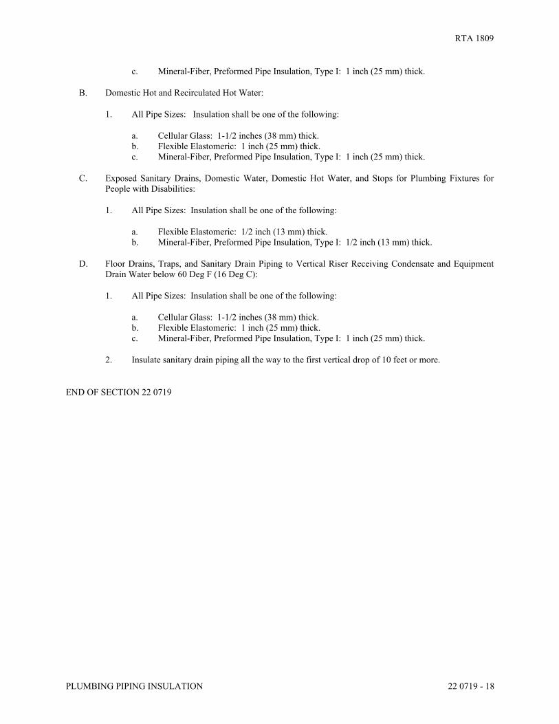
RTA 1809
PLUMBING PIPING INSULATION 22 0719 - 18
c. Mineral-Fiber, Preformed Pipe Insulation, Type I: 1 inch (25 mm) thick.
B. Domestic Hot and Recirculated Hot Water:
1. All Pipe Sizes: Insulation shall be one of the following:
a. Cellular Glass: 1-1/2 inches (38 mm) thick.b. Flexible Elastomeric: 1 inch (25 mm) thick.c. Mineral-Fiber, Preformed Pipe Insulation, Type I: 1 inch (25 mm) thick.
C. Exposed Sanitary Drains, Domestic Water, Domestic Hot Water, and Stops for Plumbing Fixtures for People with Disabilities:
1. All Pipe Sizes: Insulation shall be one of the following:
a. Flexible Elastomeric: 1/2 inch (13 mm) thick.b. Mineral-Fiber, Preformed Pipe Insulation, Type I: 1/2 inch (13 mm) thick.
D. Floor Drains, Traps, and Sanitary Drain Piping to Vertical Riser Receiving Condensate and Equipment Drain Water below 60 Deg F (16 Deg C):
1. All Pipe Sizes: Insulation shall be one of the following:
a. Cellular Glass: 1-1/2 inches (38 mm) thick.b. Flexible Elastomeric: 1 inch (25 mm) thick.c. Mineral-Fiber, Preformed Pipe Insulation, Type I: 1 inch (25 mm) thick.
2. Insulate sanitary drain piping all the way to the first vertical drop of 10 feet or more.
END OF SECTION 22 0719

RTA 1809
DOMESTIC WATER PIPING 22 1116 - 1
SECTION 22 1116 - DOMESTIC WATER PIPING
PART 1 - GENERAL
1.1 RELATED DOCUMENTS
A. Drawings and general provisions of the Contract, including General and Supplementary Conditions and Division 01 Specification Sections, apply to this Section.
1.2 SUMMARY
A. Section Includes:
1. Aboveground domestic water pipes, tubes, and fittings inside buildings.
1.3 ACTION SUBMITTALS
A. Product Data: For transition fittings and dielectric fittings.
1.4 INFORMATIONAL SUBMITTALS
A. System purging and disinfecting activities report.
B. Field quality-control reports.
1.5 FIELD CONDITIONS
A. Interruption of Existing Water Service: Do not interrupt water service to facilities occupied by Owner or others unless permitted under the following conditions and then only after arranging to provide temporary water service according to requirements indicated:
1. Notify Owner no fewer than five days in advance of proposed interruption of water service.2. Do not interrupt water service without Owner's written permission.
PART 2 - PRODUCTS
2.1 PIPING MATERIALS
A. Comply with requirements in "Piping Schedule" Article for applications of pipe, tube, fitting materials, and joining methods for specific services, service locations, and pipe sizes.
B. Potable-water piping and components shall comply with NSF 14 and NSF 61. Plastic piping components shall be marked with "NSF-pw."

RTA 1809
DOMESTIC WATER PIPING 22 1116 - 2
2.2 COPPER TUBE AND FITTINGS
A. Hard Copper Tube: ASTM B 88, Type L (ASTM B 88M, Type B) water tube, drawn temper.
B. Soft Copper Tube: ASTM B 88, Type K (ASTM B 88M, Type A) water tube, annealed temper.
C. Cast-Copper, Solder-Joint Fittings: ASME B16.18, pressure fittings.
D. Wrought-Copper, Solder-Joint Fittings: ASME B16.22, wrought-copper pressure fittings.
E. Bronze Flanges: ASME B16.24, Class 150, with solder-joint ends.
F. Copper Unions:
1. MSS SP-123.2. Cast-copper-alloy, hexagonal-stock body.3. Ball-and-socket, metal-to-metal seating surfaces.4. Solder-joint or threaded ends.
G. Copper Pressure-Seal-Joint Fittings:1. Manufacturers: Subject to compliance with requirements, provide products from one of the
following:
a. Elkhart Products Corporation.b. NIBCO Inc.c. Viega.
2. Fittings for NPS 2 (DN 50) and Smaller: Wrought-copper fitting with EPDM-rubber, O-ring seal in each end.
3. Fittings for NPS 2-1/2 to NPS 4 (DN 65 to DN 100): Cast-bronze or wrought-copper fitting with EPDM-rubber, O-ring seal in each end.
2.3 DUCTILE-IRON PIPE AND FITTINGS
A. Mechanical-Joint, Ductile-Iron Pipe:
1. AWWA C151/A21.51, with mechanical-joint bell and plain spigot end unless grooved or flanged ends are indicated.
2. Glands, Gaskets, and Bolts: AWWA C111/A21.11, ductile- or gray-iron glands, rubber gaskets, and steel bolts.
B. Standard-Pattern, Mechanical-Joint Fittings:
1. AWWA C110/A21.10, ductile or gray iron.2. Glands, Gaskets, and Bolts: AWWA C111/A21.11, ductile- or gray-iron glands, rubber gaskets,
and steel bolts.
C. Compact-Pattern, Mechanical-Joint Fittings:
1. AWWA C153/A21.53, ductile iron.2. Glands, Gaskets, and Bolts: AWWA C111/A21.11, ductile- or gray-iron glands, rubber gaskets,
and steel bolts.
D. Push-on-Joint, Ductile-Iron Pipe:

RTA 1809
DOMESTIC WATER PIPING 22 1116 - 3
1. AWWA C151/A21.51.2. Push-on-joint bell and plain spigot end unless grooved or flanged ends are indicated.
E. Standard-Pattern, Push-on-Joint Fittings:
1. AWWA C110/A21.10, ductile or gray iron.2. Gaskets: AWWA C111/A21.11, rubber.
F. Compact-Pattern, Push-on-Joint Fittings:
1. AWWA C153/A21.53, ductile iron.2. Gaskets: AWWA C111/A21.11, rubber.
G. Plain-End, Ductile-Iron Pipe: AWWA C151/A21.51.
2.4 PVC PIPE AND FITTINGS
A. PVC Pipe: ASTM D 1785, Schedule 40.
B. PVC Socket Fittings: ASTM D 2466 for Schedule 40.
C. PVC Schedule 80 Threaded Fittings: ASTM D 2464.
2.5 PIPING JOINING MATERIALS
A. Pipe-Flange Gasket Materials:
1. AWWA C110/A21.10, rubber, flat face, 1/8 inch (3.2 mm) thick or ASME B16.21, nonmetallic and asbestos free unless otherwise indicated.
2. Full-face or ring type unless otherwise indicated.
B. Metal, Pipe-Flange Bolts and Nuts: ASME B18.2.1, carbon steel unless otherwise indicated.
C. Solder Filler Metals: ASTM B 32, lead-free alloys.
D. Flux: ASTM B 813, water flushable.
E. Brazing Filler Metals: AWS A5.8/A5.8M, BCuP Series, copper-phosphorus alloys for general-duty brazing unless otherwise indicated.
F. Solvent Cements for Joining PVC Piping: ASTM D 2564. Include primer according to ASTM F 656.
1. PVC solvent cement shall have a VOC content of 510 g/L or less when calculated according to 40 CFR 59, Subpart D (EPA Method 24).
2. Adhesive primer shall have a VOC content of 550 g/L or less when calculated according to 40 CFR 59, Subpart D (EPA Method 24).
3. Solvent cement and adhesive primer shall comply with the testing and product requirements of the California Department of Health Services' "Standard Practice for the Testing of Volatile Organic Emissions from Various Sources Using Small-Scale Environmental Chambers."
G. Plastic, Pipe-Flange Gaskets, Bolts, and Nuts: Type and material recommended by piping system manufacturer unless otherwise indicated.
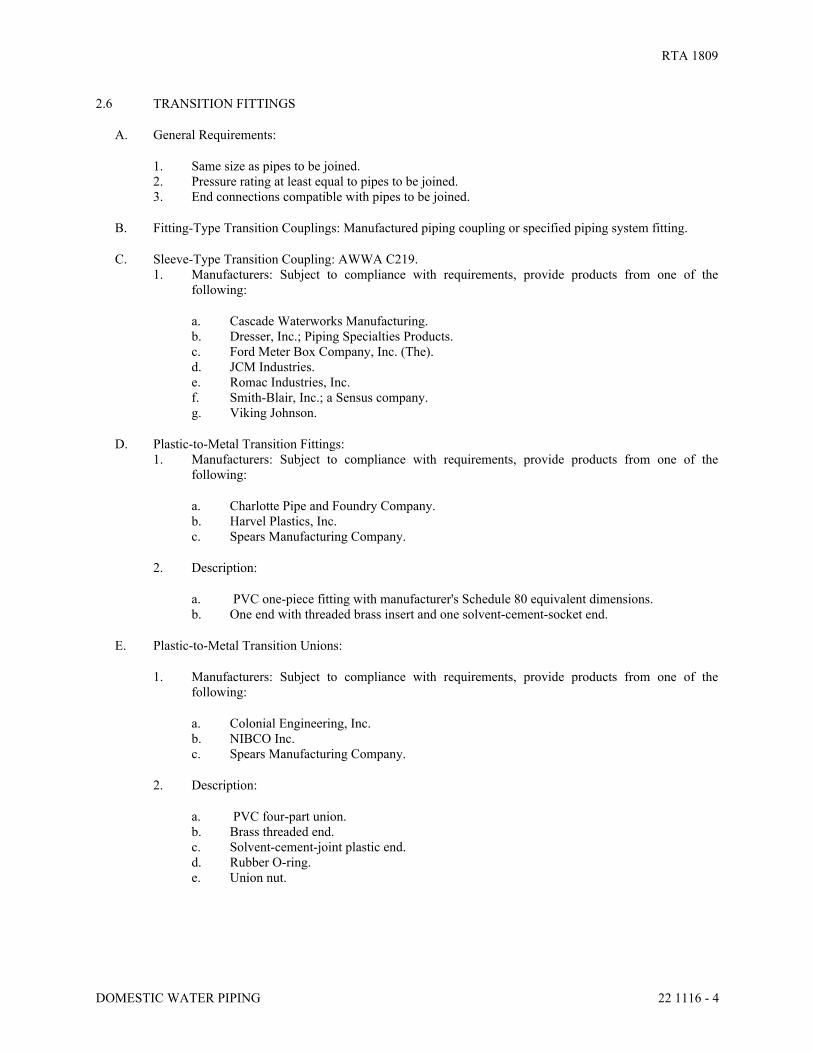
RTA 1809
DOMESTIC WATER PIPING 22 1116 - 4
2.6 TRANSITION FITTINGS
A. General Requirements:
1. Same size as pipes to be joined.2. Pressure rating at least equal to pipes to be joined.3. End connections compatible with pipes to be joined.
B. Fitting-Type Transition Couplings: Manufactured piping coupling or specified piping system fitting.
C. Sleeve-Type Transition Coupling: AWWA C219.1. Manufacturers: Subject to compliance with requirements, provide products from one of the
following:
a. Cascade Waterworks Manufacturing.b. Dresser, Inc.; Piping Specialties Products.c. Ford Meter Box Company, Inc. (The).d. JCM Industries.e. Romac Industries, Inc.f. Smith-Blair, Inc.; a Sensus company.g. Viking Johnson.
D. Plastic-to-Metal Transition Fittings:1. Manufacturers: Subject to compliance with requirements, provide products from one of the
following:
a. Charlotte Pipe and Foundry Company.b. Harvel Plastics, Inc.c. Spears Manufacturing Company.
2. Description:
a. PVC one-piece fitting with manufacturer's Schedule 80 equivalent dimensions.b. One end with threaded brass insert and one solvent-cement-socket end.
E. Plastic-to-Metal Transition Unions:
1. Manufacturers: Subject to compliance with requirements, provide products from one of the following:
a. Colonial Engineering, Inc.b. NIBCO Inc.c. Spears Manufacturing Company.
2. Description:
a. PVC four-part union.b. Brass threaded end.c. Solvent-cement-joint plastic end.d. Rubber O-ring.e. Union nut.

RTA 1809
DOMESTIC WATER PIPING 22 1116 - 5
2.7 DIELECTRIC FITTINGS
A. General Requirements: Assembly of copper alloy and ferrous materials with separating nonconductive insulating material. Include end connections compatible with pipes to be joined.
B. Dielectric Unions:1. Manufacturers: Subject to compliance with requirements, provide products from one of the
following:
a. Capitol Manufacturing Company; member of the Phoenix Forge Group.b. Central Plastics Company.c. Hart Industries International, Inc.d. Jomar International.e. Matco-Norca.f. McDonald, A. Y. Mfg. Co.g. Watts; a division of Watts Water Technologies, Inc.h. Wilkins; a Zurn company.
2. Standard: ASSE 1079.3. Pressure Rating: 125 psig (860 kPa) minimum at 180 deg F (82 deg C).4. End Connections: Solder-joint copper alloy and threaded ferrous.
C. Dielectric Flanges:
1. Manufacturers: Subject to compliance with requirements, provide products from one of thefollowing:
a. Capitol Manufacturing Company; member of the Phoenix Forge Group.b. Central Plastics Company.c. Matco-Norca.d. Watts; a division of Watts Water Technologies, Inc.e. Wilkins; a Zurn company.
2. Standard: ASSE 1079.3. Factory-fabricated, bolted, companion-flange assembly.4. Pressure Rating: 125 psig (860 kPa) minimum at 180 deg F (82 deg C).5. End Connections: Solder-joint copper alloy and threaded ferrous; threaded solder-joint copper
alloy and threaded ferrous.
D. Dielectric-Flange Insulating Kits:
1. Manufacturers: Subject to compliance with requirements, available manufacturers offering products that may be incorporated into the Work include, but are not limited to, the following:
a. Advance Products & Systems, Inc.b. Calpico, Inc.c. Central Plastics Company.d. Pipeline Seal and Insulator, Inc.
2. Nonconducting materials for field assembly of companion flanges.3. Pressure Rating: 150 psig (1035 kPa).4. Gasket: Neoprene or phenolic.5. Bolt Sleeves: Phenolic or polyethylene.6. Washers: Phenolic with steel backing washers.

RTA 1809
DOMESTIC WATER PIPING 22 1116 - 6
E. Dielectric Nipples:
1. Manufacturers: Subject to compliance with requirements, provide products from one of thefollowing:
a. Elster Perfection Corporation.b. Grinnell Mechanical Products; Tyco Fire Products LP.c. Matco-Norca.d. Precision Plumbing Products, Inc.e. Victaulic Company.
2. Standard: IAPMO PS 66.3. Electroplated steel nipple complying with ASTM F 1545.4. Pressure Rating and Temperature: 300 psig (2070 kPa) at 225 deg F (107 deg C).5. End Connections: Male threaded or grooved.6. Lining: Inert and noncorrosive, propylene.
PART 3 - EXECUTION
3.1 PIPING INSTALLATION
A. Drawing plans, schematics, and diagrams indicate general location and arrangement of domestic water piping. Indicated locations and arrangements are used to size pipe and calculate friction loss, expansion, and other design considerations. Install piping as indicated unless deviations to layout are approved on coordination drawings.
B. Install copper tubing under building slab according to CDA's "Copper Tube Handbook."
C. Install ductile-iron piping under building slab with restrained joints according to AWWA C600 and AWWA M41.
D. Install shutoff valve, hose-end drain valve, strainer, pressure gage, and test tee with valve inside the building at each domestic water-service entrance. Comply with requirements for pressure gages in Section 220519 "Meters and Gages for Plumbing Piping" and with requirements for drain valves and strainers in Section 221119 "Domestic Water Piping Specialties."
E. Install shutoff valve immediately upstream of each dielectric fitting.
F. Install water-pressure-reducing valves downstream from shutoff valves. Comply with requirements for pressure-reducing valves in Section 221119 "Domestic Water Piping Specialties."
G. Install domestic water piping level without pitch and plumb.
H. Rough-in domestic water piping for water-meter installation according to utility company's requirements.
I. Install piping concealed from view and protected from physical contact by building occupants unless otherwise indicated and except in equipment rooms and service areas.
J. Install piping indicated to be exposed and piping in equipment rooms and service areas at right angles or parallel to building walls. Diagonal runs are prohibited unless specifically indicated otherwise.
K. Install piping above accessible ceilings to allow sufficient space for ceiling panel removal, and coordinate with other services occupying that space.

RTA 1809
DOMESTIC WATER PIPING 22 1116 - 7
L. Install piping to permit valve servicing.
M. Install nipples, unions, special fittings, and valves with pressure ratings the same as or higher than the system pressure rating used in applications below unless otherwise indicated.
N. Install piping free of sags and bends.
O. Install fittings for changes in direction and branch connections.
P. Install unions in copper tubing at final connection to each piece of equipment, machine, and specialty.
Q. Install pressure gages on suction and discharge piping for each plumbing pump and packaged booster pump. Comply with requirements for pressure gages in Section 220519 "Meters and Gages for Plumbing Piping."
R. Install thermostats in hot-water circulation piping. Comply with requirements for thermostats in Section 221123 "Domestic Water Pumps."
S. Install thermometers on outlet piping from each water heater. Comply with requirements for thermometers in Section 220519 "Meters and Gages for Plumbing Piping."
T. Install sleeves for piping penetrations of walls, ceilings, and floors. Comply with requirements for sleeves specified in Section 220517 "Sleeves and Sleeve Seals for Plumbing Piping."
U. Install sleeve seals for piping penetrations of concrete walls and slabs. Comply with requirements for sleeve seals specified in Section 220517 "Sleeves and Sleeve Seals for Plumbing Piping."
V. Install escutcheons for piping penetrations of walls, ceilings, and floors. Comply with requirements for escutcheons specified in Section 220518 "Escutcheons for Plumbing Piping."
3.2 JOINT CONSTRUCTION
A. Ream ends of pipes and tubes and remove burrs. Bevel plain ends of steel pipe.
B. Remove scale, slag, dirt, and debris from inside and outside of pipes, tubes, and fittings before assembly.
C. Threaded Joints: Thread pipe with tapered pipe threads according to ASME B1.20.1. Cut threads full and clean using sharp dies. Ream threaded pipe ends to remove burrs and restore full ID. Join pipe fittings and valves as follows:
1. Apply appropriate tape or thread compound to external pipe threads.2. Damaged Threads: Do not use pipe or pipe fittings with threads that are corroded or damaged.
D. Brazed Joints for Copper Tubing: Comply with CDA's "Copper Tube Handbook," "Brazed Joints" chapter.
E. Soldered Joints for Copper Tubing: Apply ASTM B 813, water-flushable flux to end of tube. Join copper tube and fittings according to ASTM B 828 or CDA's "Copper Tube Handbook."
F. Pressure-Sealed Joints for Copper Tubing: Join copper tube and pressure-seal fittings with tools recommended by fitting manufacturer.
G. Push-on Joints for Copper Tubing: Clean end of tube. Measure insertion depth with manufacturer's depth gage. Join copper tube and push-on-joint fittings by inserting tube to measured depth.

RTA 1809
DOMESTIC WATER PIPING 22 1116 - 8
H. Flanged Joints: Select appropriate asbestos-free, nonmetallic gasket material in size, type, and thickness suitable for domestic water service. Join flanges with gasket and bolts according to ASME B31.9.
I. Joint Construction for Solvent-Cemented Plastic Piping: Clean and dry joining surfaces. Join pipe and fittings according to the following:
1. Comply with ASTM F 402 for safe-handling practice of cleaners, primers, and solvent cements. Apply primer.
2. PVC Piping: Join according to ASTM D 2855.
J. Joints for Dissimilar-Material Piping: Make joints using adapters compatible with materials of both piping systems.
3.3 TRANSITION FITTING INSTALLATION
A. Install transition couplings at joints of dissimilar piping.
B. Transition Fittings in Underground Domestic Water Piping:
1. Fittings for NPS 1-1/2 (DN 40) and Smaller: Fitting-type coupling.2. Fittings for NPS 2 (DN 50) and Larger: Sleeve-type coupling.
C. Transition Fittings in Aboveground Domestic Water Piping NPS 2 (DN 50) and Smaller: Plastic-to-metal transition fittings or unions.
3.4 DIELECTRIC FITTING INSTALLATION
A. Install dielectric fittings in piping at connections of dissimilar metal piping and tubing.
B. Dielectric Fittings for NPS 2 (DN 50) and Smaller: Use dielectric couplings, nipples or unions.
C. Dielectric Fittings for NPS 2-1/2 to NPS 4 (DN 65 to DN 100): Use dielectric flange kits.
D. Dielectric Fittings for NPS 5 (DN 125) and Larger: Use dielectric flange kits.
3.5 HANGER AND SUPPORT INSTALLATION
A. Comply with requirements for seismic-restraint devices in Section 220548 "Vibration and Seismic Controls for Plumbing Piping and Equipment."
B. Comply with requirements for pipe hanger, support products, and installation in Section 220529 "Hangers and Supports for Plumbing Piping and Equipment."
1. Vertical Piping: MSS Type 8 or 42, clamps.2. Individual, Straight, Horizontal Piping Runs:
a. 100 Feet (30 m) and Less: MSS Type 1, adjustable, steel clevis hangers.b. Longer Than 100 Feet (30 m): MSS Type 43, adjustable roller hangers.c. Longer Than 100 Feet (30 m) if Indicated: MSS Type 49, spring cushion rolls.
3. Multiple, Straight, Horizontal Piping Runs 100 Feet (30 m) or Longer: MSS Type 44, pipe rolls. Support pipe rolls on trapeze.

RTA 1809
DOMESTIC WATER PIPING 22 1116 - 9
4. Base of Vertical Piping: MSS Type 52, spring hangers.
C. Support vertical piping and tubing at base and at each floor.
D. Rod diameter may be reduced one size for double-rod hangers, to a minimum of 3/8 inch (10 mm).
E. Install hangers for copper tubing with the following maximum horizontal spacing and minimum rod diameters:
1. NPS 3/4 (DN 20) and Smaller: 60 inches (1500 mm) with 3/8-inch (10-mm) rod.2. NPS 1 and NPS 1-1/4 (DN 25 and DN 32): 72 inches (1800 mm) with 3/8-inch (10-mm) rod.3. NPS 1-1/2 and NPS 2 (DN 40 and DN 50): 96 inches (2400 mm) with 3/8-inch (10-mm) rod.4. NPS 2-1/2 (DN 65): 108 inches (2700 mm) with 1/2-inch (13-mm) rod.5. NPS 3 to NPS 5 (DN 80 to DN 125): 10 feet (3 m) with 1/2-inch (13-mm) rod.6. NPS 6 (DN 150): 10 feet (3 m) with 5/8-inch (16-mm) rod.7. NPS 8 (DN 200): 10 feet (3 m) with 3/4-inch (19-mm) rod.
F. Install supports for vertical copper tubing every 10 feet (3 m).
G. Support piping and tubing not listed in this article according to MSS SP-69 and manufacturer's written instructions.
3.6 CONNECTIONS
A. Drawings indicate general arrangement of piping, fittings, and specialties.
B. When installing piping adjacent to equipment and machines, allow space for service and maintenance.
C. Connect domestic water piping to exterior water-service piping. Use transition fitting to join dissimilar piping materials.
D. Connect domestic water piping to water-service piping with shutoff valve; extend and connect to the following:
1. Domestic Water Booster Pumps: Cold-water suction and discharge piping.2. Water Heaters: Cold-water inlet and hot-water outlet piping in sizes indicated, but not smaller than
sizes of water heater connections.3. Plumbing Fixtures: Cold- and hot-water-supply piping in sizes indicated, but not smaller than that
required by plumbing code.4. Equipment: Cold- and hot-water-supply piping as indicated, but not smaller than equipment
connections. Provide shutoff valve and union for each connection. Use flanges instead of unions for NPS 2-1/2 (DN 65) and larger.
3.7 IDENTIFICATION
A. Identify system components. Comply with requirements for identification materials and installation in Section 220553 "Identification for Plumbing Piping and Equipment."
B. Label pressure piping with system operating pressure.

RTA 1809
DOMESTIC WATER PIPING 22 1116 - 10
3.8 FIELD QUALITY CONTROL
A. Perform the following tests and inspections:
1. Piping Inspections:
a. Do not enclose, cover, or put piping into operation until it has been inspected and approved by authorities having jurisdiction.
b. During installation, notify authorities having jurisdiction at least one day before inspection must be made. Perform tests specified below in presence of authorities having jurisdiction:
1) Roughing-in Inspection: Arrange for inspection of piping before concealing or closing in after roughing in and before setting fixtures.
2) Final Inspection: Arrange for authorities having jurisdiction to observe tests specified in "Piping Tests" Subparagraph below and to ensure compliance with requirements.
c. Reinspection: If authorities having jurisdiction find that piping will not pass tests or inspections, make required corrections and arrange for reinspection.
d. Reports: Prepare inspection reports and have them signed by authorities having jurisdiction.
2. Piping Tests:
a. Fill domestic water piping. Check components to determine that they are not air bound and that piping is full of water.
b. Test for leaks and defects in new piping and parts of existing piping that have been altered, extended, or repaired. If testing is performed in segments, submit a separate report for each test, complete with diagram of portion of piping tested.
c. Leave new, altered, extended, or replaced domestic water piping uncovered and unconcealed until it has been tested and approved. Expose work that was covered or concealed before it was tested.
d. Cap and subject piping to static water pressure of 50 psig (345 kPa) above operating pressure, without exceeding pressure rating of piping system materials. Isolate test source and allow it to stand for four hours. Leaks and loss in test pressure constitute defects that must be repaired.
e. Repair leaks and defects with new materials, and retest piping or portion thereof until satisfactory results are obtained.
f. Prepare reports for tests and for corrective action required.
B. Domestic water piping will be considered defective if it does not pass tests and inspections.
C. Prepare test and inspection reports.
3.9 ADJUSTING
A. Perform the following adjustments before operation:
1. Close drain valves, hydrants, and hose bibbs.2. Open shutoff valves to fully open position.3. Open throttling valves to proper setting.4. Adjust balancing valves in hot-water-circulation return piping to provide adequate flow.
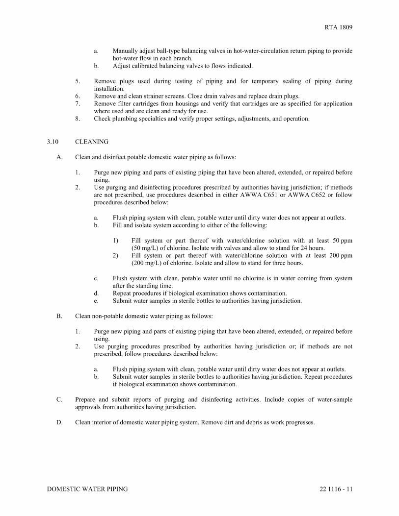
RTA 1809
DOMESTIC WATER PIPING 22 1116 - 11
a. Manually adjust ball-type balancing valves in hot-water-circulation return piping to provide hot-water flow in each branch.
b. Adjust calibrated balancing valves to flows indicated.
5. Remove plugs used during testing of piping and for temporary sealing of piping during installation.
6. Remove and clean strainer screens. Close drain valves and replace drain plugs.7. Remove filter cartridges from housings and verify that cartridges are as specified for application
where used and are clean and ready for use.8. Check plumbing specialties and verify proper settings, adjustments, and operation.
3.10 CLEANING
A. Clean and disinfect potable domestic water piping as follows:
1. Purge new piping and parts of existing piping that have been altered, extended, or repaired before using.
2. Use purging and disinfecting procedures prescribed by authorities having jurisdiction; if methods are not prescribed, use procedures described in either AWWA C651 or AWWA C652 or follow procedures described below:
a. Flush piping system with clean, potable water until dirty water does not appear at outlets.b. Fill and isolate system according to either of the following:
1) Fill system or part thereof with water/chlorine solution with at least 50 ppm (50 mg/L) of chlorine. Isolate with valves and allow to stand for 24 hours.
2) Fill system or part thereof with water/chlorine solution with at least 200 ppm (200 mg/L) of chlorine. Isolate and allow to stand for three hours.
c. Flush system with clean, potable water until no chlorine is in water coming from system after the standing time.
d. Repeat procedures if biological examination shows contamination.e. Submit water samples in sterile bottles to authorities having jurisdiction.
B. Clean non-potable domestic water piping as follows:
1. Purge new piping and parts of existing piping that have been altered, extended, or repaired before using.
2. Use purging procedures prescribed by authorities having jurisdiction or; if methods are not prescribed, follow procedures described below:
a. Flush piping system with clean, potable water until dirty water does not appear at outlets.b. Submit water samples in sterile bottles to authorities having jurisdiction. Repeat procedures
if biological examination shows contamination.
C. Prepare and submit reports of purging and disinfecting activities. Include copies of water-sample approvals from authorities having jurisdiction.
D. Clean interior of domestic water piping system. Remove dirt and debris as work progresses.
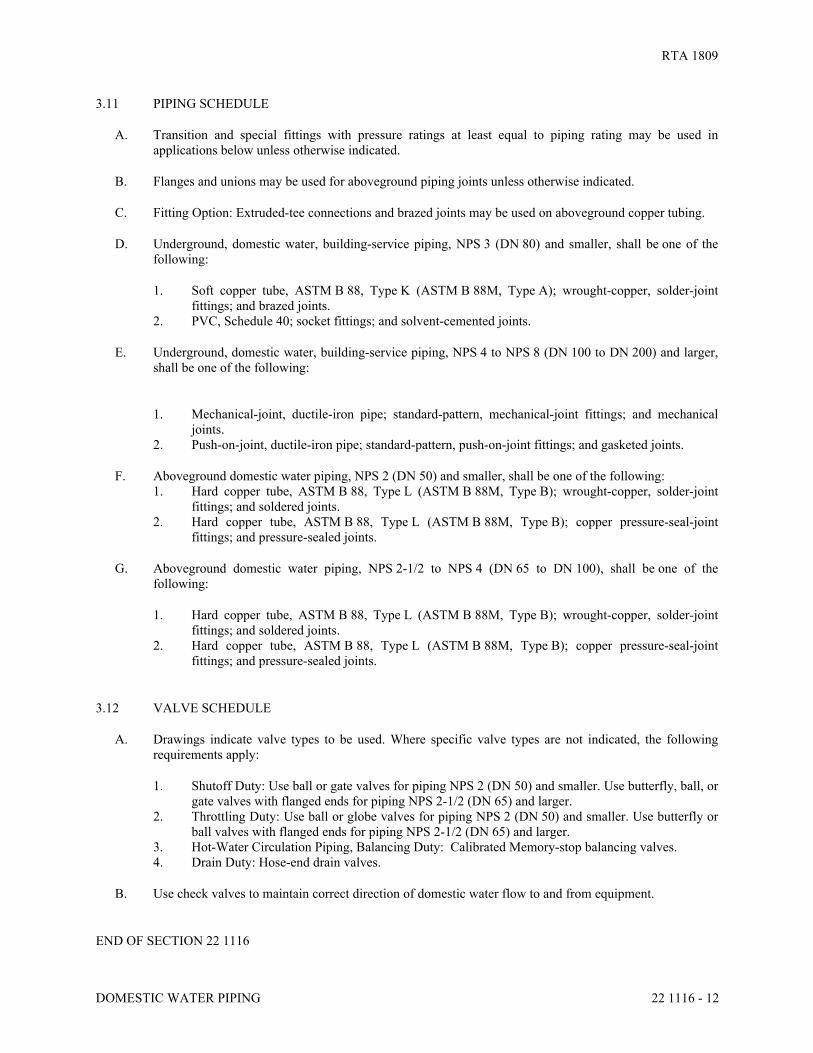
RTA 1809
DOMESTIC WATER PIPING 22 1116 - 12
3.11 PIPING SCHEDULE
A. Transition and special fittings with pressure ratings at least equal to piping rating may be used in applications below unless otherwise indicated.
B. Flanges and unions may be used for aboveground piping joints unless otherwise indicated.
C. Fitting Option: Extruded-tee connections and brazed joints may be used on aboveground copper tubing.
D. Underground, domestic water, building-service piping, NPS 3 (DN 80) and smaller, shall be one of the following:
1. Soft copper tube, ASTM B 88, Type K (ASTM B 88M, Type A); wrought-copper, solder-joint fittings; and brazed joints.
2. PVC, Schedule 40; socket fittings; and solvent-cemented joints.
E. Underground, domestic water, building-service piping, NPS 4 to NPS 8 (DN 100 to DN 200) and larger, shall be one of the following:
1. Mechanical-joint, ductile-iron pipe; standard-pattern, mechanical-joint fittings; and mechanical joints.
2. Push-on-joint, ductile-iron pipe; standard-pattern, push-on-joint fittings; and gasketed joints.
F. Aboveground domestic water piping, NPS 2 (DN 50) and smaller, shall be one of the following:1. Hard copper tube, ASTM B 88, Type L (ASTM B 88M, Type B); wrought-copper, solder-joint
fittings; and soldered joints.2. Hard copper tube, ASTM B 88, Type L (ASTM B 88M, Type B); copper pressure-seal-joint
fittings; and pressure-sealed joints.
G. Aboveground domestic water piping, NPS 2-1/2 to NPS 4 (DN 65 to DN 100), shall be one of the following:
1. Hard copper tube, ASTM B 88, Type L (ASTM B 88M, Type B); wrought-copper, solder-joint fittings; and soldered joints.
2. Hard copper tube, ASTM B 88, Type L (ASTM B 88M, Type B); copper pressure-seal-joint fittings; and pressure-sealed joints.
3.12 VALVE SCHEDULE
A. Drawings indicate valve types to be used. Where specific valve types are not indicated, the following requirements apply:
1. Shutoff Duty: Use ball or gate valves for piping NPS 2 (DN 50) and smaller. Use butterfly, ball, or gate valves with flanged ends for piping NPS 2-1/2 (DN 65) and larger.
2. Throttling Duty: Use ball or globe valves for piping NPS 2 (DN 50) and smaller. Use butterfly or ball valves with flanged ends for piping NPS 2-1/2 (DN 65) and larger.
3. Hot-Water Circulation Piping, Balancing Duty: Calibrated Memory-stop balancing valves.4. Drain Duty: Hose-end drain valves.
B. Use check valves to maintain correct direction of domestic water flow to and from equipment.
END OF SECTION 22 1116
RTA 1809
SANITARY WASTE AND VENT PIPING 22 1316 - 1
SECTION 22 1316 - SANITARY WASTE AND VENT PIPING
PART 1 - GENERAL
1.1 RELATED DOCUMENTS
A. Drawings and general provisions of the Contract, including General and Supplementary Conditions and Division 01 Specification Sections, apply to this Section.
1.2 SUMMARY
A. Section Includes:
1. Pipe, tube, and fittings.2. Specialty pipe fittings.
B. Related Sections:
1. Section 221313 "Facility Sanitary Sewers" for sanitary sewerage piping and structures outside the building.
1.3 PERFORMANCE REQUIREMENTS
A. Components and installation shall be capable of withstanding the following minimum working pressure unless otherwise indicated:
1. Soil, Waste, and Vent Piping: 10-foot head of water (30 kPa).2. Waste, Force-Main Piping: 100 psig (690 kPa).
1.4 ACTION SUBMITTALS
A. Product Data: For each type of product indicated.
1.5 QUALITY ASSURANCE
A. Piping materials shall bear label, stamp, or other markings of specified testing agency.
B. Hubless Couplings shall be certified by NSF to the CISPI-310 Standard, and bear the NSF mark.
C. Comply with NSF/ANSI 14, "Plastics Piping Systems Components and Related Materials," for plastic piping components. Include marking with "NSF-dwv" for plastic drain, waste, and vent piping and "NSF-sewer" for plastic sewer piping.
RTA 1809
SANITARY WASTE AND VENT PIPING 22 1316 - 2
1.6 PROJECT CONDITIONS
A. Interruption of Existing Sanitary Waste Service: Do not interrupt service to facilities occupied by Owner or others unless permitted under the following conditions and then only after arranging to provide temporary service according to requirements indicated:
1. Notify Owner no fewer than 5 days in advance of proposed interruption of sanitary waste service.2. Do not proceed with interruption of sanitary waste service without Owner's written permission.
PART 2 - PRODUCTS
2.1 PIPING MATERIALS
A. Comply with requirements in "Piping Schedule" Article for applications of pipe, tube, fitting materials, and joining methods for specific services, service locations, and pipe sizes.
2.2 HUB-AND-SPIGOT, CAST-IRON SOIL PIPE AND FITTINGS
A. Pipe and Fittings: ASTM A 74, Service and Extra Heavy class(es). ). Pipe and fittings shall be marked with the collective trademark of the Cast Iron Soil Pipe Institute.
B. Gaskets: ASTM C 564, rubber.
C. Calking Materials: ASTM B 29, pure lead and oakum or hemp fiber.
2.3 HUBLESS, CAST-IRON SOIL PIPE AND FITTINGS
A. Pipe and Fittings: ASTM A 888 or CISPI 301. ). Pipe and fittings shall be marked with the collective trademark of the Cast Iron Soil Pipe Institute.
B. Solvent Stack Fittings: ASME B16.45 or ASSE 1043, hubless, cast-iron aerator and deaerator drainage fittings.
C. CISPI, Hubless-Piping Couplings:
1. Manufacturers: Subject to compliance with requirements, provide products from one of the following:
a. ANACO-Husky.b. Dallas Specialty & Mfg. Co.c. Fernco Inc.d. Matco-Norca, Inc.e. MIFAB, Inc.f. Mission Rubber Company; a division of MCP Industries, Inc.g. Stant.h. Tyler Pipe.
2. Standards: ASTM C 1277 and CISPI 310.3. Description: Stainless-steel corrugated shield with stainless-steel bands and tightening devices;
and ASTM C 564, rubber sleeve with integral, center pipe stop.
RTA 1809
SANITARY WASTE AND VENT PIPING 22 1316 - 3
D. Cast-Iron, Hubless-Piping Couplings:
1. Manufacturers: Subject to compliance with requirements, provide products from one of the following:
a. MG Piping Products Company.
2. Standard: ASTM C 1277.3. Description: Two-piece ASTM A 48/A 48M, cast-iron housing; stainless-steel bolts and nuts; and
ASTM C 564, rubber sleeve with integral, center pipe stop.
2.4 COPPER TUBE AND FITTINGS
A. Copper DWV Tube: ASTM B 306, drainage tube, drawn temper.
B. Copper Drainage Fittings: ASME B16.23, cast copper or ASME B16.29, wrought copper, solder-joint fittings.
C. Solder: ASTM B 32, lead free with ASTM B 813, water-flushable flux.
2.5 PVC PIPE AND FITTINGS
A. Solid-Wall PVC Pipe: ASTM D 2665, drain, waste, and vent.
B. PVC Socket Fittings: ASTM D 2665, made to ASTM D 3311, drain, waste, and vent patterns and to fit Schedule 40 pipe.
C. Adhesive Primer: ASTM F 656.
1. Adhesive primer shall have a VOC content of 550 g/L or less when calculated according to 40 CFR 59, Subpart D (EPA Method 24).
2. Adhesive primer shall comply with the testing and product requirements of the California Department of Health Services' "Standard Practice for the Testing of Volatile Organic Emissions from Various Sources Using Small-Scale Environmental Chambers."
D. Solvent Cement: ASTM D 2564.
1. PVC solvent cement shall have a VOC content of 510 g/L or less when calculated according to 40 CFR 59, Subpart D (EPA Method 24).
2. Solvent cement shall comply with the testing and product requirements of the California Department of Health Services' "Standard Practice for the Testing of Volatile Organic Emissions from Various Sources Using Small-Scale Environmental Chambers."
2.6 SPECIALTY PIPE FITTINGS
A. Transition Couplings:
1. General Requirements: Fitting or device for joining piping with small differences in OD's or of different materials. Include end connections same size as and compatible with pipes to be joined.
2. Fitting-Type Transition Couplings: Manufactured piping coupling or specified piping system fitting.
3. Unshielded, Nonpressure Transition Couplings:

RTA 1809
SANITARY WASTE AND VENT PIPING 22 1316 - 4
a. Manufacturers: Subject to compliance with requirements, provide products from one of the following:
1) Dallas Specialty & Mfg. Co.2) Fernco Inc.3) Mission Rubber Company; a division of MCP Industries, Inc.4) Plastic Oddities; a division of Diverse Corporate Technologies, Inc.
b. Standard: ASTM C 1173.c. Description: Elastomeric, sleeve-type, reducing or transition pattern. Include shear ring and
corrosion-resistant-metal tension band and tightening mechanism on each end.d. Sleeve Materials:
1) For Cast-Iron Soil Pipes: ASTM C 564, rubber.2) For Plastic Pipes: ASTM F 477, elastomeric seal or ASTM D 5926, PVC.3) For Dissimilar Pipes: ASTM D 5926, PVC or other material compatible with pipe
materials being joined.
4. Shielded, Nonpressure Transition Couplings:
a. Manufacturers: Subject to compliance with requirements, provide products from one of the following:
1) Cascade Waterworks Mfg. Co.2) Mission Rubber Company; a division of MCP Industries, Inc.
b. Standard: ASTM C 1460.c. Description: Elastomeric or rubber sleeve with full-length, corrosion-resistant outer shield
and corrosion-resistant-metal tension band and tightening mechanism on each end.
5. Pressure Transition Couplings:
a. Manufacturers: Subject to compliance with requirements, provide products from one of the following:
1) Cascade Waterworks Mfg. Co.2) Dresser, Inc.3) EBAA Iron, Inc.4) JCM Industries, Inc.5) Romac Industries, Inc.6) Smith-Blair, Inc.; a Sensus company.7) The Ford Meter Box Company, Inc.8) Viking Johnson.
b. Standard: AWWA C219.c. Description: Metal, sleeve-type same size as, with pressure rating at least equal to, and
ends compatible with, pipes to be joined.d. Center-Sleeve Material: Manufacturer's standard.e. Gasket Material: Natural or synthetic rubber.f. Metal Component Finish: Corrosion-resistant coating or material.
B. Dielectric Fittings:
1. General Requirements: Assembly of copper alloy and ferrous materials with separating nonconductive insulating material. Include end connections compatible with pipes to be joined.
RTA 1809
SANITARY WASTE AND VENT PIPING 22 1316 - 5
2. Dielectric Unions:
a. Manufacturers: Subject to compliance with requirements, provide products from one of the following:
1) Capitol Manufacturing Company.2) Central Plastics Company.3) Hart Industries International, Inc.4) Jomar International Ltd.5) Matco-Norca, Inc.6) McDonald, A. Y. Mfg. Co.7) Watts Regulator Co.; a division of Watts Water Technologies, Inc.8) Wilkins; a Zurn company.
b. Description:
1) Standard: ASSE 1079.2) Pressure Rating: 125 psig (860 kPa) minimum at 180 deg F (82 deg C).3) End Connections: Solder-joint copper alloy and threaded ferrous.
3. Dielectric Flanges:
a. Manufacturers: Subject to compliance with requirements, provide products from one of the following:
1) Capitol Manufacturing Company.2) Central Plastics Company.3) Matco-Norca, Inc.4) Watts Regulator Co.; a division of Watts Water Technologies, Inc.5) Wilkins; a Zurn company.
b. Description:
1) Standard: ASSE 1079.2) Factory-fabricated, bolted, companion-flange assembly.3) Pressure Rating: 125 psig (860 kPa) minimum at 180 deg F (82 deg C).4) End Connections: Solder-joint copper alloy and threaded ferrous; threaded solder-
joint copper alloy and threaded ferrous.
4. Dielectric-Flange Insulating Kits:
a. Manufacturers: Subject to compliance with requirements, provide products from one of the following:
1) Advance Products & Systems, Inc.2) Calpico, Inc.3) Central Plastics Company.4) Pipeline Seal and Insulator, Inc.
b. Description:
1) Nonconducting materials for field assembly of companion flanges.2) Pressure Rating: 150 psig (1035 kPa).3) Gasket: Neoprene or phenolic.4) Bolt Sleeves: Phenolic or polyethylene.

RTA 1809
SANITARY WASTE AND VENT PIPING 22 1316 - 6
5) Washers: Phenolic with steel backing washers.
5. Dielectric Nipples:
a. Manufacturers: Subject to compliance with requirements, provide products from one of the following:
1) Elster Perfection.2) Grinnell Mechanical Products.3) Matco-Norca, Inc.4) Precision Plumbing Products, Inc.5) Victaulic Company.
b. Description:
1) Standard: IAPMO PS 662) Electroplated steel nipple.3) Pressure Rating: 300 psig (2070 kPa) at 225 deg F (107 deg C).4) End Connections: Male threaded or grooved.5) Lining: Inert and noncorrosive, propylene.
PART 3 - EXECUTION
3.1 PIPING INSTALLATION
A. Drawing plans, schematics, and diagrams indicate general location and arrangement of piping systems. Indicated locations and arrangements were used to size pipe and calculate friction loss, expansion, pump sizing, and other design considerations. Install piping as indicated unless deviations to layout are approved on coordination drawings.
B. Install piping in concealed locations unless otherwise indicated and except in equipment rooms and service areas.
C. Install piping indicated to be exposed and piping in equipment rooms and service areas at right angles or parallel to building walls. Diagonal runs are prohibited unless specifically indicated otherwise.
D. Install piping above accessible ceilings to allow sufficient space for ceiling panel removal.
E. Install piping to permit valve servicing.
F. Install piping at indicated slopes.
G. Install piping free of sags and bends.
H. Install fittings for changes in direction and branch connections.
I. Install piping to allow application of insulation.
J. Make changes in direction for soil and waste drainage and vent piping using appropriate branches, bends, and long-sweep bends. Sanitary tees and short-sweep 1/4 bends may be used on vertical stacks if change in direction of flow is from horizontal to vertical. Use long-turn, double Y-branch and 1/8-bend fittings if two fixtures are installed back to back or side by side with common drain pipe. Straight tees, elbows, and crosses may be used on vent lines. Do not change direction of flow more than 90 degrees. Use proper size

RTA 1809
SANITARY WASTE AND VENT PIPING 22 1316 - 7
of standard increasers and reducers if pipes of different sizes are connected. Reducing size of drainage piping in direction of flow is prohibited.
K. Lay buried building drainage piping beginning at low point of each system. Install true to grades and alignment indicated, with unbroken continuity of invert. Place hub ends of piping upstream. Install required gaskets according to manufacturer's written instructions for use of lubricants, cements, and other installation requirements. Maintain swab in piping and pull past each joint as completed.
L. Install soil and waste drainage and vent piping at the following minimum slopes unless otherwise indicated:
1. Building Sanitary Drain: 2 percent downward in direction of flow for piping NPS 3 (DN 80) and smaller; 1 percent downward in direction of flow for piping NPS 4 (DN 100) and larger.
2. Horizontal Sanitary Drainage Piping: 2 percent downward in direction of flow.3. Vent Piping: 1 percent down toward vertical fixture vent or toward vent stack.
M. Install steel piping according to applicable plumbing code.
N. Install aboveground copper tubing according to CDA's "Copper Tube Handbook."
O. Install underground PVC piping according to ASTM D 2321.
P. Install engineered soil and waste drainage and vent piping systems as follows:
1. Combination Waste and Vent: Comply with standards of authorities having jurisdiction.2. Solvent Drainage System: Comply with ASSE 1043 and solvent fitting manufacturer's written
installation instructions.3. Reduced-Size Venting: Comply with standards of authorities having jurisdiction.
Q. Plumbing Specialties:1. Install cleanouts at grade and extend to where building sanitary drains connect to building sanitary
sewers in sanitary drainage gravity-flow piping. Install cleanout fitting with closure plug inside the building in sanitary drainage force-main piping. Comply with requirements for cleanouts specified in Section 221319 "Sanitary Waste Piping Specialties."
2. Install drains in sanitary drainage gravity-flow piping. Comply with requirements for drains specified in Section 221319 "Sanitary Waste Piping Specialties."
R. Do not enclose, cover, or put piping into operation until it is inspected and approved by authorities having jurisdiction.
S. Install sleeves for piping penetrations of walls, ceilings, and floors. Comply with requirements for sleeves specified in Section 220517 "Sleeves and Sleeve Seals for Plumbing Piping."
T. Install sleeve seals for piping penetrations of concrete walls and slabs. Comply with requirements for sleeve seals specified in Section 220517 "Sleeves and Sleeve Seals for Plumbing Piping."
U. Install escutcheons for piping penetrations of walls, ceilings, and floors. Comply with requirements for escutcheons specified in Section 220518 "Escutcheons for Plumbing Piping."
3.2 JOINT CONSTRUCTION
A. Join hub-and-spigot, cast-iron soil piping with gasket joints according to CISPI's "Cast Iron Soil Pipe and Fittings Handbook" for compression joints.

RTA 1809
SANITARY WASTE AND VENT PIPING 22 1316 - 8
B. Join hub-and-spigot, cast-iron soil piping with calked joints according to CISPI's "Cast Iron Soil Pipe and Fittings Handbook" for lead-and-oakum calked joints.
C. Join hubless, cast-iron soil piping according to CISPI 310 and CISPI's "Cast Iron Soil Pipe and Fittings Handbook" for hubless-piping coupling joints.
D. Threaded Joints: Thread pipe with tapered pipe threads according to ASME B1.20.1. Cut threads full and clean using sharp dies. Ream threaded pipe ends to remove burrs and restore full ID. Join pipe fittings and valves as follows:
1. Apply appropriate tape or thread compound to external pipe threads unless dry seal threading is specified.
2. Damaged Threads: Do not use pipe or pipe fittings with threads that are corroded or damaged. Do not use pipe sections that have cracked or open welds.
E. Join copper tube and fittings with soldered joints according to ASTM B 828. Use ASTM B 813, water-flushable, lead-free flux and ASTM B 32, lead-free-alloy solder.
F. Plastic, Nonpressure-Piping, Solvent-Cement Joints: Clean and dry joining surfaces. Join pipe and fittings according to the following:
1. Comply with ASTM F 402 for safe-handling practice of cleaners, primers, and solvent cements.2. PVC Piping: Join according to ASTM D 2855 and ASTM D 2665 Appendixes.
3.3 SPECIALTY PIPE FITTING INSTALLATION
A. Transition Couplings:
1. Install transition couplings at joints of piping with small differences in OD's.2. In Drainage Piping: Unshielded, nonpressure transition couplings.3. In Aboveground Force Main Piping: Fitting-type transition couplings.4. In Underground Force Main Piping:
a. NPS 1-1/2 (DN 40) and Smaller: Fitting-type transition couplings.b. NPS 2 (DN 50) and Larger: Pressure transition couplings.
B. Dielectric Fittings:
1. Install dielectric fittings in piping at connections of dissimilar metal piping and tubing.2. Dielectric Fittings for NPS 2 (DN 50) and Smaller: Use dielectric nipples or unions.3. Dielectric Fittings for NPS 2-1/2 to NPS 4 (DN 65 to DN 100): Use dielectric flanges or flange
kits.
3.4 VALVE INSTALLATION
A. General valve installation requirements are specified in Section 220523.12 "Ball Valves for Plumbing Piping," Section 220523.13 "Butterfly Valves for Plumbing Piping," Section 220523.14 "Check Valves for Plumbing Piping," and Section 220523.15 "Gate Valves for Plumbing Piping."
B. Shutoff Valves:
1. Install shutoff valve on each sewage pump discharge.2. Install gate or full-port ball valve for piping NPS 2 (DN 50) and smaller.
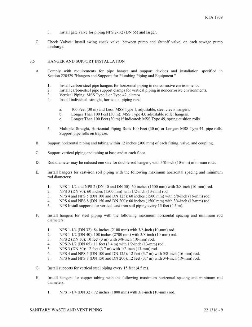
RTA 1809
SANITARY WASTE AND VENT PIPING 22 1316 - 9
3. Install gate valve for piping NPS 2-1/2 (DN 65) and larger.
C. Check Valves: Install swing check valve, between pump and shutoff valve, on each sewage pump discharge.
3.5 HANGER AND SUPPORT INSTALLATION
A. Comply with requirements for pipe hanger and support devices and installation specified in Section 220529 "Hangers and Supports for Plumbing Piping and Equipment."
1. Install carbon-steel pipe hangers for horizontal piping in noncorrosive environments.2. Install carbon-steel pipe support clamps for vertical piping in noncorrosive environments.3. Vertical Piping: MSS Type 8 or Type 42, clamps.4. Install individual, straight, horizontal piping runs:
a. 100 Feet (30 m) and Less: MSS Type 1, adjustable, steel clevis hangers.b. Longer Than 100 Feet (30 m): MSS Type 43, adjustable roller hangers.c. Longer Than 100 Feet (30 m) if Indicated: MSS Type 49, spring cushion rolls.
5. Multiple, Straight, Horizontal Piping Runs 100 Feet (30 m) or Longer: MSS Type 44, pipe rolls. Support pipe rolls on trapeze.
B. Support horizontal piping and tubing within 12 inches (300 mm) of each fitting, valve, and coupling.
C. Support vertical piping and tubing at base and at each floor.
D. Rod diameter may be reduced one size for double-rod hangers, with 3/8-inch (10-mm) minimum rods.
E. Install hangers for cast-iron soil piping with the following maximum horizontal spacing and minimum rod diameters:
1. NPS 1-1/2 and NPS 2 (DN 40 and DN 50): 60 inches (1500 mm) with 3/8-inch (10-mm) rod.2. NPS 3 (DN 80): 60 inches (1500 mm) with 1/2-inch (13-mm) rod.3. NPS 4 and NPS 5 (DN 100 and DN 125): 60 inches (1500 mm) with 5/8-inch (16-mm) rod.4. NPS 6 and NPS 8 (DN 150 and DN 200): 60 inches (1500 mm) with 3/4-inch (19-mm) rod.5. NPS Install supports for vertical cast-iron soil piping every 15 feet (4.5 m).
F. Install hangers for steel piping with the following maximum horizontal spacing and minimum rod diameters:
1. NPS 1-1/4 (DN 32): 84 inches (2100 mm) with 3/8-inch (10-mm) rod.2. NPS 1-1/2 (DN 40): 108 inches (2700 mm) with 3/8-inch (10-mm) rod.3. NPS 2 (DN 50): 10 feet (3 m) with 3/8-inch (10-mm) rod.4. NPS 2-1/2 (DN 65): 11 feet (3.4 m) with 1/2-inch (13-mm) rod.5. NPS 3 (DN 80): 12 feet (3.7 m) with 1/2-inch (13-mm) rod.6. NPS 4 and NPS 5 (DN 100 and DN 125): 12 feet (3.7 m) with 5/8-inch (16-mm) rod.7. NPS 6 and NPS 8 (DN 150 and DN 200): 12 feet (3.7 m) with 3/4-inch (19-mm) rod.
G. Install supports for vertical steel piping every 15 feet (4.5 m).
H. Install hangers for copper tubing with the following maximum horizontal spacing and minimum rod diameters:
1. NPS 1-1/4 (DN 32): 72 inches (1800 mm) with 3/8-inch (10-mm) rod.

RTA 1809
SANITARY WASTE AND VENT PIPING 22 1316 - 10
2. NPS 1-1/2 and NPS 2 (DN 40 and DN 50): 96 inches (2400 mm) with 3/8-inch (10-mm) rod.3. NPS 2-1/2 (DN 65): 108 inches (2700 mm) with 1/2-inch (13-mm) rod.4. NPS 3 and NPS 5 (DN 80 and DN 125): 10 feet (3 m) with 1/2-inch (13-mm) rod.5. NPS 8 (DN 200): 10 feet (3 m) with 3/4-inch (19-mm) rod.
I. Install supports for vertical copper tubing every 10 feet (3 m).
J. Support piping and tubing not listed above according to MSS SP-69 and manufacturer's written instructions.
3.6 CONNECTIONS
A. Drawings indicate general arrangement of piping, fittings, and specialties.
B. Connect soil and waste piping to exterior sanitary sewerage piping. Use transition fitting to join dissimilar piping materials.
C. Connect drainage and vent piping to the following:
1. Plumbing Fixtures: Connect drainage piping in sizes indicated, but not smaller than required by plumbing code.
2. Plumbing Fixtures and Equipment: Connect atmospheric vent piping in sizes indicated, but not smaller than required by authorities having jurisdiction.
3. Plumbing Specialties: Connect drainage and vent piping in sizes indicated, but not smaller than required by plumbing code.
4. Install test tees (wall cleanouts) in conductors near floor and floor cleanouts with cover flush with floor.
5. Equipment: Connect drainage piping as indicated. Provide shutoff valve if indicated and union for each connection. Use flanges instead of unions for connections NPS 2-1/2 (DN 65) and larger.
D. Connect force-main piping to the following:
1. Sanitary Sewer: To exterior force main.2. Sewage Pump: To sewage pump discharge.
E. Where installing piping adjacent to equipment, allow space for service and maintenance of equipment.
F. Make connections according to the following unless otherwise indicated:
1. Install unions, in piping NPS 2 (DN 50) and smaller, adjacent to each valve and at final connection to each piece of equipment.
2. Install flanges, in piping NPS 2-1/2 (DN 65) and larger, adjacent to flanged valves and at final connection to each piece of equipment.
3.7 IDENTIFICATION
A. Identify exposed sanitary waste and vent piping. Comply with requirements for identification specified in Section 220553 "Identification for Plumbing Piping and Equipment."

RTA 1809
SANITARY WASTE AND VENT PIPING 22 1316 - 11
3.8 FIELD QUALITY CONTROL
A. During installation, notify authorities having jurisdiction at least 24 hours before inspection must be made. Perform tests specified below in presence of authorities having jurisdiction.
1. Roughing-in Inspection: Arrange for inspection of piping before concealing or closing-in after roughing-in and before setting fixtures.
2. Final Inspection: Arrange for final inspection by authorities having jurisdiction to observe tests specified below and to ensure compliance with requirements.
B. Reinspection: If authorities having jurisdiction find that piping will not pass test or inspection, make required corrections and arrange for reinspection.
C. Reports: Prepare inspection reports and have them signed by authorities having jurisdiction.
D. Test sanitary drainage and vent piping according to procedures of authorities having jurisdiction. or, in absence of published procedures, as follows:
1. Test for leaks and defects in new piping and parts of existing piping that have been altered, extended, or repaired. If testing is performed in segments, submit separate report for each test, complete with diagram of portion of piping tested.
2. Leave uncovered and unconcealed new, altered, extended, or replaced drainage and vent piping until it has been tested and approved. Expose work that was covered or concealed before it was tested.
3. Roughing-in Plumbing Test Procedure: Test drainage and vent piping except outside leaders on completion of roughing-in. Close openings in piping system and fill with water to point of overflow, but not less than 10-foot head of water (30 kPa). From 15 minutes before inspection starts to completion of inspection, water level must not drop. Inspect joints for leaks.
4. Finished Plumbing Test Procedure: After plumbing fixtures have been set and traps filled with water, test connections and prove they are gastight and watertight. Plug vent-stack openings on roof and building drains where they leave building. Introduce air into piping system equal to pressure of 1-inch wg (250 Pa). Use U-tube or manometer inserted in trap of water closet to measure this pressure. Air pressure must remain constant without introducing additional air throughout period of inspection. Inspect plumbing fixture connections for gas and water leaks.
5. Repair leaks and defects with new materials and retest piping, or portion thereof, until satisfactory results are obtained.
6. Prepare reports for tests and required corrective action.
E. Test force-main piping according to procedures of authorities having jurisdiction or, in absence of published procedures, as follows:
1. Leave uncovered and unconcealed new, altered, extended, or replaced force-main piping until it has been tested and approved. Expose work that was covered or concealed before it was tested.
2. Cap and subject piping to static-water pressure of 50 psig (345 kPa) above operating pressure, without exceeding pressure rating of piping system materials. Isolate test source and allow to stand for four hours. Leaks and loss in test pressure constitute defects that must be repaired.
3. Repair leaks and defects with new materials and retest piping, or portion thereof, until satisfactory results are obtained.
4. Prepare reports for tests and required corrective action.
3.9 CLEANING AND PROTECTION
A. Clean interior of piping. Remove dirt and debris as work progresses.

RTA 1809
SANITARY WASTE AND VENT PIPING 22 1316 - 12
B. Protect drains during remainder of construction period to avoid clogging with dirt and debris and to prevent damage from traffic and construction work.
C. Place plugs in ends of uncompleted piping at end of day and when work stops.
3.10 PIPING SCHEDULE
A. Flanges and unions may be used on aboveground pressure piping unless otherwise indicated.
B. Aboveground, soil, waste and vent piping NPS 6 (DN 150) and smaller shall be any of the following:
1. Service class, cast-iron soil pipe and fittings; gaskets; and gasketed joints.2. Hubless, cast-iron soil pipe and fittings; hubless-piping couplings; and coupled joints.3. Copper DWV tube, copper drainage fittings, and soldered joints.4. Dissimilar Pipe-Material Couplings: Unshielded, nonpressure transition couplings.
PVC Piping is NOT Allowed Above Ground.
C. Aboveground sanitary-sewage force mains NPS 1-1/2 and NPS 2 (DN 40 and DN 50) shall be the following:
1. Hard copper tube, Type L (Type B); copper pressure fittings; and soldered joints.
END OF SECTION 22 1316
RTA 1809
PLUMBING FIXTURES 22 4000 - 1
SECTION 22 4000 - PLUMBING FIXTURES
PART 1 - GENERAL
1.1 RELATED DOCUMENTS
A. Drawings and general provisions of the Contract, including General and Supplementary Conditions and Division 01 Specification Sections, apply to this Section.
1.2 SUMMARY
A. This Section includes the following conventional plumbing fixtures and related components:
1. Water closets.2. Urinals.3. Lavatories.
1.3 DEFINITIONS`
A. Accessible: Describes a plumbing fixture, building, facility, or portion thereof that can be approached, entered, and used by physically handicapped people.
B. Accessory: Device that adds effectiveness, convenience, or improved appearance to a fixture but is not essential to its operation.
C. Appurtenance: Device or assembly designed to perform some useful function when attached to or used with a fixture.
D. Equipment: Device used with plumbing fixtures or plumbing systems to perform a certain function for plumbing fixtures but that is not part of the fixture.
E. Fitting: Fitting installed on or attached to a fixture to control the flow of water into or out of the fixture.
F. Fixture: Installed receptor connected to the water distribution system, that receives and makes available potable water and discharges the used liquid or liquid-borne wastes directly or indirectly into the drainage system. The term "Fixture" means the actual receptor, except when used in a general application where terms "Fixture" and "Plumbing Fixture" include associated trim, fittings, accessories, appliances, appurtenances, support, and equipment
G. Roughing-In: Installation of piping and support for the fixture prior to the actual installation of the fixture.
H. Support: Device normally concealed in building construction, for supporting and securing plumbing fixtures to walls and structural members. Supports for urinals, lavatories, and sinks are made in types suitable for fixture construction and the mounting required. Categories of supports are:
1. Carrier: Heavy Duty Floor-mounted support for wall-mounted water closet.2. Chair Carrier: Support for wall-hung fixture, having steel pipe uprights that transfer weight to the floor.
I. Trim: Hardware and miscellaneous parts, specific to a fixture and normally supplied with it required to complete fixture assembly and installation.
RTA 1809
PLUMBING FIXTURES 22 4000 - 2
1.4 ACTION SUBMITTALS
A. Product Data: For each type of product.
1. Include construction details, material descriptions, dimensions of individual components and profiles, and finishes for lavatories.
2. Include rated capacities, operating characteristics, electrical characteristics, and furnished specialties and accessories.
B. Shop Drawings: Include diagrams for power, signal, and control wiring.
1.5 CLOSEOUT SUBMITTALS
A. Operation and Maintenance Data: For plumbing fixtures and faucets to include in emergency, operation, and operation and maintenance manuals.
1.6 QUALITY ASSURANCE
A. Source Limitations: Obtain plumbing fixtures, faucets, and other components of each category through one source from a single manufacturer.
1. Exception: If fixtures, faucets, or other components are not available from a single manufacturer, obtain similar products from other manufacturers specified for that category.
B. Electrical Components, Devices, and Accessories: Listed and labeled as defined in NFPA 70, Article 100, by a testing agency acceptable to authorities having jurisdiction, and marked for intended use.
C. Regulatory Requirements: Comply with requirements in ICC A117.1, "Accessible and Usable Buildings and Facilities"; Public Law 90-480, "Architectural Barriers Act"; and Public Law 101-336, "Americans with Disabilities Act"; for plumbing fixtures for people with disabilities.
D. Regulatory Requirements: Comply with requirements in Public Law 102-486, "Energy Policy Act," about water flow and consumption rates for plumbing fixtures.
E. NSF Standard: Comply with NSF 61, "Drinking Water System Components--Health Effects," for fixture materials that will be in contact with potable water.
F. Select combinations of fixtures and trim, faucets, fittings, and other components that are compatible.
1.7 DELIVERY, STORAGE AND HANDLING
A. Store fixtures where environmental conditions are uniformly maintained within the manufacturer's recommended temperatures to prevent damage.
B. Store fixtures and trim in the manufacturer's original shipping containers. Do not stack containers or store in such a manner that may cause damage to the fixture or trim

RTA 1809
PLUMBING FIXTURES 22 4000 - 3
1.8 EXTRA MATERIALS
A. Furnish extra materials described below that match products installed and that are packaged with protective covering for storage and identified with labels describing contents.
1. Faucet Washers and O-Rings: Equal to 10 percent of amount of each type and size installed.2. Faucet Cartridges and O-Rings: Equal to 5 percent of amount of each type and size installed.
PART 2 - PRODUCTS
A. WATER CLOSETS
a. American Standard Companies, Inc.b. Crane Plumbing, L.L.C./Fiat Products.c. Kohler Co.
2.2 URINALS
a. American Standard Companies, Inc.b. Crane Plumbing, L.L.C./Fiat Products.c. Kohler Co.
2.3 LAVATORIES
a. American Standard Companies, Inc.b. Briggs Plumbing Products, Inc.c. Crane Plumbing, L.L.C./Fiat Products.d. Eljer.e. Gerber Plumbing Fixtures LLC.f. Kohler Co.g. Zurn Plumbing Products.
2.4 SINKS
a. American Standard, Inc.b. Crane Plumbing/Fiat Products.c. Elkayd. Kohler Co.e. Just.
2.5 DRINKING FOUNTAINS
a. Halsey Taylor, A Household International Co.b. Elkay Manufacturing Co.c. Haws Drinking Faucet Co.d. Acorn Engineering Company.
2.6 MOP BASINS
a. Fiat b. Stearn Williams.c. Acorn

RTA 1809
PLUMBING FIXTURES 22 4000 - 4
2.7 FLUSH VALVES
a. Zurnb. Sloanc. Moen
2.8 FAUCETS
a. Zurnb. Deltac. Cambridged. American Standarde. Moen
2.9 PLUMBING FIXTURES – See plumbing drawings for schedule of fixtures.
2.10 PLUMBING FIXTURE SUPPORTS
A. Carriers are specified below by Zurn catalog numbers. Carriers of equal quality, type and supporting capacities will be acceptable, provided they are approved by the State Health Department.
1. Water Closets -- Z-1204-XH4-45. Adjustable coupling shall be cast iron (plastic will not be allowed) and Z-1280.2. Urinals -- ZR-1221.3. Lavatories – ZR-1231
PART 3 - EXECUTION
3.0 EXECUTION
3.1 EXAMINATION
A. Examine roughing-in of water supply and sanitary drainage and vent piping systems to verify actual locations of piping connections before plumbing fixture installation.
B. Examine cabinets, counters, floors, and walls for suitable conditions where fixtures will be installed.
C. Proceed with installation only after unsatisfactory conditions have been corrected.
3.2 INSTALLATION
A. Assemble plumbing fixtures, trim, fittings, and other components according to manufacturers' written instructions.
B. Install off-floor supports, affixed to building substrate, for wall-mounting fixtures.
2. Use carrier supports with waste fitting and seal for back-outlet fixtures.

RTA 1809
PLUMBING FIXTURES 22 4000 - 5
3. Use carrier supports without waste fitting for fixtures with tubular waste piping.4. Use chair-type carrier supports with rectangular steel uprights for accessible fixtures.
C. Install back-outlet, wall-mounting fixtures onto waste fitting seals and attach to supports.
D. Install floor-mounting fixtures on closet flanges or other attachments to piping or building substrate.
E. Install wall-mounting fixtures with tubular waste piping attached to supports.
F. Install floor-mounting, back-outlet water closets attached to building floor substrate and wall bracket and onto waste fitting seals.
G. Install counter-mounting fixtures in and attached to casework.
H. Install fixtures level and plumb according to roughing-in drawings.
I. Install water-supply piping with stop on each supply to each fixture to be connected to water distribution piping. Attach supplies to supports or substrate within pipe spaces behind fixtures. Install stops in locations where they can be easily reached for operation.
2. Exception: Use ball, gate, or globe valves if supply stops are not specified with fixture. Valves are specified in Division 22 Section "General-Duty Valves for Plumbing Piping."
J. Install trap and tubular waste piping on drain outlet of each fixture to be directly connected to sanitary drainage system.
K. Install tubular waste piping on drain outlet of each fixture to be indirectly connected to drainage system.
L. Install flushometer valves for accessible water closets and urinals with handle mounted on wide side of compartment. Install other actuators in locations that are easy for people with disabilities to reach.
M. Install tanks for accessible, tank-type water closets with lever handle mounted on wide side of compartment.
N. Install toilet seats on water closets.
O. Install trap-seal liquid in dry urinals.
P. Install faucet-spout fittings with specified flow rates and patterns in faucet spouts if faucets are not available with required rates and patterns. Include adapters if required.
Q. Install traps on fixture outlets.
2. Exception: Omit trap on fixtures with integral traps.3. Exception: Omit trap on indirect wastes, unless otherwise indicated.
R. Install disposer in outlet of each sink indicated to have disposer. Install switch where indicated or in wall adjacent to sink if location is not indicated.
S. Install hot-water dispensers in back top surface of sink or in countertop with spout over sink.
T. Install escutcheons at piping wall ceiling penetrations in exposed, finished locations and within cabinets and millwork. Use deep-pattern escutcheons if required to conceal protruding fittings. Escutcheons are specified in Division 22 Section "Escutcheons for Plumbing Piping."
RTA 1809
PLUMBING FIXTURES 22 4000 - 6
U. Set service basins in leveling bed of cement grout. Grout is specified in Division 22 Section "Common Work Results for Plumbing."
V. Seal joints between fixtures and walls, floors, and countertops using sanitary-type, one-part, mildew-resistant silicone sealant. Match sealant color to fixture color. Sealants are specified in Division 07 Section "Joint Sealants."
3.3 CONNECTIONS
A. Piping installation requirements are specified in other Division 22 Sections. Drawings indicate general arrangement of piping, fittings, and specialties.
B. Connect fixtures with water supplies, stops, and risers, and with traps, soil, waste, and vent piping. Use size fittings required to match fixtures.
C. Ground equipment according to Division 26 Section "Grounding and Bonding for Electrical Systems."
D. Connect wiring according to Division 26 Section "Low-Voltage Electrical Power Conductors and Cables."
3.4 FIELD QUALITY CONTROL
A. Verify that installed plumbing fixtures are categories and types specified for locations where installed.
B. Check that plumbing fixtures are complete with trim, faucets, fittings, and other specified components.
C. Inspect installed plumbing fixtures for damage. Replace damaged fixtures and components.
D. Test installed fixtures after water systems are pressurized for proper operation. Replace malfunctioning fixtures and components, then retest. Repeat procedure until units operate properly.
E. Install fresh batteries in sensor-operated mechanisms.
3.5 ADJUSTING
A. Operate and adjust faucets and controls. Replace damaged and malfunctioning fixtures, fittings, and controls.
B. Adjust water pressure at faucets to produce proper flow and stream.
C. Replace washers and seals of leaking and dripping faucets and stops.
D. Install fresh batteries in sensor-operated mechanisms.
3.6 CLEANING
A. Clean fixtures, faucets, and other fittings with manufacturers' recommended cleaning methods and materials. Do the following:
2. Remove faucet spouts and strainers, remove sediment and debris, and reinstall strainers and spouts.

RTA 1809
PLUMBING FIXTURES 22 4000 - 7
3. Remove sediment and debris from drains.
B. After completing installation of exposed, factory-finished fixtures, faucets, and fittings, inspect exposed finishes and repair damaged finishes.
3.7 PROTECTION
A. Provide protective covering for installed fixtures and fittings.
B. Do not allow use of plumbing fixtures for temporary facilities unless approved in writing by Owner.
END OF SECTION 22 4000


RTA 1809
GENERAL PROVISIONS FOR HVAC SYSTEMS 23 0000 - 1
SECTION 23 0000– GENERAL PROVISIONS FOR HVAC SYSTEMS
PART 1 - GENERAL
1.1 GENERAL
A. The General Conditions, Special Conditions, Supplemental Conditions, Instructions to Bidders, and other Contract Documents apply to this branch of the work as well as to the other branches.
B. Provide the materials (piping, ductwork, wiring, conduit, software, equipment, equipment accessories, etc.) and labor necessary for complete and functioning HVAC systems. The Drawings and Specifications are intended to indicate complete working systems. Provide complete and properly working systems, even if all materials and labor necessary to achieve this are not specifically shown on the Drawings or specified.
C. The Contractor shall familiarize himself with the work of all other trades, general type construction, and the relationship of his work to other sections. He shall examine all working drawings, specifications and conditions affecting his work. The Contractor shall visit the premises and thoroughly familiarize himself with all details of the work and working conditions, verify all dimensions in the field and advise the Engineer of any discrepancy before fabricating or performing any work.
D. The work shall include complete testing of all equipment, piping and ductwork at the completion of the work and making any minor connection changes or adjustments necessary for the proper functioning of the system and equipment.
E. Perform any necessary temporary work during construction.
F. Work under this section shall conform to governing codes, ordinances and regulations of the City, County and State.
G. The Contractor shall be responsible for any errors in fabrication, for the correct fitting, installation and erection of the various HVAC systems.
1.2 POWDER ACTUATED CONCRETE FASTENERS
A. Obtain written approval from the structural engineer before using powder-actuated concrete fasteners.
B. Do not use powder-actuated concrete fasteners for lightweight-aggregate concretes or for slabs less than 4 inches (100 mm) thick.
1.3 SUSPENSION FROM METAL DECKING
A. Do not use metal decking for suspension of piping, ductwork or equipment. Hang items from top member of joist or provide additional structure to span between top members if needed.
1.4 COORDINATION BETWEEN TRADES
A. Demand and examine all Drawings and Specifications pertaining to the construction before installing the work described and shown under these Drawings and Specifications. Cooperate with all other Contractors

RTA 1809
GENERAL PROVISIONS FOR HVAC SYSTEMS 23 0000 - 2
in locating piping, ductwork, conduit, openings, chases and equipment in order to avoid conflict with any other Contractor's work. Give special attention to points where ducts or piping must cross other ducts or piping and where ducts, piping and conduit must fur into the walls and columns. All work installed above a lay-in ceiling must be coordinated and installed so there is a minimum of 4 inches between the top of the ceiling grid and the bottom of the installation.
B. Make known to other trades intended positioning of materials and intended order of work. Determine intended position of work of other trades and intended order of installation.
1.5 DISCREPANCIES
A. If any discrepancies occur between the accompanying Drawings and these Specifications and Drawings and Specifications covering other Contracts, report such discrepancies to the Architect/Engineer far enough in advance so that a workable solution can be presented. No extra payment will be allowed for relocation of piping, ductwork, conduit and equipment not installed in accordance with the above instructions, and which interferes with work and equipment of other Contractors.
1.6 EXISTING PIPE AND SERVICES
A. Existing piping and services are located as accurately as possible from available information, but it shall be the Contractor's responsibility to locate, determine exact elevations and make required connections to such lines and services in manner approved by the Architect/Engineer.
B. Maintain in operating condition active utilities encountered in the utility installation. Repair to the satisfaction of the Architect/ Engineer and the Owner any surface or subsurface improvements damaged during the course of the work, unless such improvement is shown to be abandoned or removed.
1.7 CONTINUOUS OPERATION AND CUTOVER
A. To facilitate the continuous operation of the existing utilities, no utility service shall be tapped into without prior notification of 48 hours to and approval received from the designated authority of the utility company.
1.8 ACCESSIBILITY
A. Install equipment and materials to provide required access for servicing and maintenance. Coordinate the final location of concealed equipment and devices requiring access with final location of required access panels and doors. Allow ample space for removal of all parts that require replacement or servicing.
B. Extend all grease fittings to an accessible location.
1.9 ROUGH-IN
A. Verify final locations for rough-ins with field measurements and with the requirements of the actual equipment to be connected.
1.10 HVAC INSTALLATIONS
A. Coordinate HVAC equipment and materials installation with other building components.

RTA 1809
GENERAL PROVISIONS FOR HVAC SYSTEMS 23 0000 - 3
B. Verify all dimensions by field measurements. Field verify existing conditions and all required measurements before fabricating any piping, ductwork or equipment.
C. Arrange for chases, slots, and openings in other building components to allow for HVAC installations.
D. Coordinate the installation of required supporting devices and sleeves to be set in poured in place concrete and other structural components, as they are constructed.
E. Sequence, coordinate, and integrate installations of HVAC materials and equipment for efficient flow of the Work. Give particular attention to large equipment requiring positioning prior to closing-in the building.
F. Coordinate the cutting and patching of building components to accommodate the installation of HVAC equipment and materials.
G. Where mounting heights are not detailed or dimensioned, install HVAC services and overhead equipment to provide the maximum headroom possible.
H. Install HVAC equipment to facilitate maintenance and repair or replacement of equipment components. As much as practical, connect equipment for ease of disconnecting, with minimum of interference with other installations.
I. Coordinate the installation of HVAC materials and equipment above ceilings with suspension system, light fixtures, and other installations.
J. Coordinate connection of HVAC systems with exterior underground and overhead utilities and services. Comply with requirements of governing regulations, franchised service companies, and controlling agencies. Provide required connection for each service.
K. Do not install HVAC work where it will interfere with work of other trades.
L. Do not install HVAC work where it will interfere with access to control panels on HVAC and/or electrical equipment.
M. Do not install HVAC work where it will interfere with access space around HVAC and electrical equipment. Do not install piping where it will interfere with removal of HVAC coils, filters or fan shafts.
N. Do not install piping so close to ceiling that ceiling tiles in accessible ceilings cannot be removed without damaging them.
O. Do not install HVAC work over the top of electrical equipment. Maintain minimum distances away from electrical equipment as required by the Electric Code.
P. Photographs: When all inaccessible mechanical work is installed and before any wallboards or hard ceilings installation is to begin, the contractor is to photograph all mechanical/electrical work in all inaccessible ceilings and walls. Each photograph is to have a label as a part of the photograph that indicates the orientation (i.e., north wall, south wall and etc.) and the room location. One copy of the photographs with a written description of each filename including orientation and room location are to be presented to the owner in digital (jpg) format on flash drive or compact disk. The resolution of the picture is to be of a level that is required to clearly show the location of all mechanical and electrical work.
RTA 1809
GENERAL PROVISIONS FOR HVAC SYSTEMS 23 0000 - 4
1.11 DISPOSAL OF SURPLUS AND WASTE MATERIALS
A. Disposal: Remove surplus satisfactory soil and waste material, including unsatisfactory soil, trash, and debris, and legally dispose of it off the Owner's property.
1.12 WORKING DRAWINGS
A. Scale of drawings is approximate. Do not scale the drawings to determine locations of mechanical work. Exact locations, dimensions and elevations shall be governed by field conditions. Make field measurements of building before fabricating or installing equipment or materials.
B. Drawings are based on physical dimensions of one or more manufacturer's equipment. Other approved equipment shall be of such dimensions that it can be readily installed in available space, leaving ample clearance for proper maintenance.
C. Intent of drawings is to show systems and sizes. Drawings do not necessarily show all required offsets. Work shall be installed to conform with space limitations. Offsets, transitions, fittings, etc., shall be provided as part of the Contract where required to attain this objective.
1.13 EQUIPMENT MOUNTING
A. Mount equipment with moving parts, such as compressors, fans, air handling units, etc., on vibration supports suitable for the purpose of minimizing noise and vibration transmission unless otherwise specified. In addition, isolate equipment from external connections such as piping, ducts, etc., with flexible connectors, vibration isolators, or other approved means.
B. Provide each piece of equipment or apparatus suspended from the ceiling or mounted above the floor level with suitable structural support, pipe stand, platform or carrier as approved by the Architect/Engineer.
C. Gasket and seal to mounting surface flush and surface mounted equipment such as diffusers, grilles, etc.
1.14 PAINTING
A. Paint the following items.
1. Exposed mechanical piping, valve bodies and fittings - bare and insulated, including hangers, platforms, etc.
2. Exposed ductwork, whether or not insulated, and any grilles, diffusers, etc., not factory finished.3. “Exposed” shall mean exposed to view, such as, in mechanical spaces, tunnels, on roofs and in
rooms with no suspended ceilings.
B. Colors of piping and ductwork shall be as specified in the "Identification for HVAC Piping and Equipment” section of the Specifications. See “color coding” in identification schedules.
C. Painting shall be done in accordance with the "Painting" section of the specifications unless otherwise specified under other sections of the specifications,
D. Do not paint aluminum and stainless steel equipment, motor and identification plates, tags, etc.
E. Do not paint piping and ductwork concealed in walls or above suspended ceilings.

RTA 1809
GENERAL PROVISIONS FOR HVAC SYSTEMS 23 0000 - 5
1.15 DEBRIS
A. Remove from the site any debris and dirt caused by the work. Maintain the premises in a clean and orderly condition.
1.16 PROTECTION OF EQUIPMENT AND MATERIALS
A. Provide suitable protection from dampness damage, dirt, etc., for equipment and materials during construction and until final acceptance by the Owner. Keep ends of piping and ductwork capped off when work on them is not in progress. Such protection shall be by a means acceptable to the Architect/Engineer.
1.17 EQUIPMENT CONNECTIONS
A. Make connections to equipment furnished by others whenever such equipment is shown on any part of the drawings or mentioned in any section of the specifications.
B. Verify equipment locations and the sizes, number, locations, and types of connections to be made before installation of any such equipment.
1.18 CLEANING UP
A. After completion of the work and before final acceptance of the work, thoroughly clean equipment and materials and remove foreign matter such as grease, dirt, labels, stickers, etc., from the exterior of piping, equipment and associated fabrications.
1.19 EQUIPMENT INSTALLATION INSTRUCTIONS
A. Install HVAC piping, ductwork and equipment in strict accordance with manufacturer's recommendations. Provide equipment accessories necessary for proper operation or recommended by the manufacturer, even if such accessories are not shown on the drawings or mentioned in the specifications.
1.20 PERMITS, CODES AND APPROVALS
A. Permits. Obtain and pay for the permits and licenses necessary for the complete HVAC systems from the authorities governing such work.
1. Reference Division 22 "Common Work Results for Plumbing" for list of specific tap fees.
B. Codes. Installation shall be in accordance with applicable codes and regulations, including but not limited to the following:
1. City or County Building Inspector 2. National and Local Electric Codes 3. Kentucky Building Code and its referenced codes4. Kentucky Boiler Code5. Kentucky Energy Code 6. Kentucky State Fire Marshal 7. Local Fire Codes 8. Local Building Inspections

RTA 1809
GENERAL PROVISIONS FOR HVAC SYSTEMS 23 0000 - 6
C. Approvals. All work must be approved by the Architect/Engineer before final payment is made.
1.21 SUBSTITUTION OF MATERIALS AND EQUIPMENT
A. When making a shop drawing submittal for materials and/or equipment of a different manufacturer than that specified, it shall be understood and agreed that such substitution if approved will be made without cost to the Owner, regardless of changes in connections, spacing, electrical service, etc.
1.22 WORKMANSHIP
A. Work shall be performed by mechanics skilled in their respective trades and shall present appearance typical of best trade practice. Work not installed in this manner shall be repaired, removed or replaced, or otherwise remedied as directed by the Architect/Engineer.
1.23 RECORD DRAWINGS
A. Keep accurate record of deviations from drawings, particularly where work is concealed. Submit one (1) set of drawings marked to show changes when work is completed.
1.24 SUPERVISION
A. The Contractor shall personally supervise the work or have a competent superintendent, satisfactory to the Architect/Engineer and Owner on the work at all times during progress with full authority to act.
B. The Contractor shall lay out his work and be responsible for any necessary lines, levels, elevations and measurements. He must verify the figures shown on the drawings before laying out the work and will be held responsible for any error resulting from his failure to do so. Work at the site of the project shall be observed by the Architect/Engineer or his representative.
C. Final Inspection: At the time of final inspection of the work performed under this Contract, systems shall be complete in every respect and in perfect operating condition. Surplus materials of every character resulting from work of this section shall have been removed. Sanitary sewers shall be free from sand, silt or other obstructions. Any defect discovered in the utilities subsequent to this inspection shall have been corrected.
1.25 STRUCTURAL RESPONSIBILITY
A. The Contractor shall be responsible for properly shoring, bracing, supporting, etc., any existing and/or new construction to guard against cracking, settling, collapsing, displacing, or weakening. No structural member shall be cut or otherwise weakened in any manner without the written consent of the Architect/Engineer.
B. Any damage occurring to the existing and/or new structures, due to failure to exercise proper precautions or due to action of the elements, shall be promptly and properly made good to the satisfaction of the Owner or Architect/Engineer, without cost to either the Owner or the Architect/ Engineer.

RTA 1809
GENERAL PROVISIONS FOR HVAC SYSTEMS 23 0000 - 7
1.26 OPENINGS
A. This Contractor shall be responsible for the openings he may require in floors, walls, roof or ceilings of any type of new or existing construction whether or not shown on the Architectural, Structural or Mechanical Drawings.
B. Openings that have been shown on the Architectural and/or Structural Drawings will be provided under other Divisions; however, the responsibility for the correct size and location of such openings shall be that of this Contractor.
C. Openings that have not been shown on the Architectural and/or Structural Drawings shall be provided by this Contractor.
D. Review and conform to all structural requirements as detailed or specified in the Structural drawings and specifications.
1.27 CUTTING, FITTING AND PATCHING
A. Before doing any cutting or drilling, Contractor shall obtain permission from the Architect/Engineer and shall follow his instructions as to how proposed cutting or drilling is to be done.
B. Each respective Contractor shall do any cutting, patching, drilling of masonry, steel, wood or iron work and any fitting necessary for the proper installation of apparatus and materials included in these specifications or governed thereby.
C. General: Employ skilled workmen to perform cutting and patching. Proceed with cutting and patching at the earliest feasible time and complete without delay.
D. Cut existing construction to provide for installation of other components or performance of other construction activities and the subsequent fitting and patching required to restore surfaces to their original condition.
E. Coordinate with the Structural Engineer BEFORE drilling, cutting, notching, etc., any new or existing structural members. Obtain written permission from Structural Engineer before doing such work. Locations and sizes of openings and methods of cutting or drilling such openings must be approved in advance by the Structural Engineer. Positively identify exact locations of reinforcing bars or tension cables in structural members by X-raying or other methods approved by the Structural Engineer if required by the Structural Engineer.
F. Cutting: Cut existing construction using methods least likely to damage elements to be retained or adjoining construction. Where possible review proposed procedures with the original installer; comply with the original installer's recommendations.
G. In general, where cutting is required use hand or small power tools designed for sawing or grinding, not hammering and chopping. Cut holes and slots neatly to size required with minimum disturbance of adjacent surfaces. Temporarily cover openings when not in use.
H. To avoid marring existing finished surfaces, cut or drill from the exposed or finished side into concealed surfaces.
I. Cut through concrete and masonry using a cutting machine such as a carborundum saw or diamond core drill.

RTA 1809
GENERAL PROVISIONS FOR HVAC SYSTEMS 23 0000 - 8
J. Comply with requirements of applicable Sections of Division 23 where cutting and patching requires excavating and backfilling.
K. The patching and finishing shall be done in a workmanlike manner to the satisfaction of the Architect/Engineer.
L. Patch any openings in existing floors, walls, ceilings or roof, left by removal of existing mechanical work.
M. Review and conform to all structural requirements as detailed or specified in the Structural drawings and specifications.
1.28 TEMPORARY UTILITIES
A. In any installation that requires deletion of existing services to install new services, a means of providing temporary service for the intermediate period is to be provided. The means of providing temporary service is to be reviewed and revised as required by the Engineer. This means of providing temporary service is to include but not limited to piping and its associated fittings, ductwork and its associated fittings, valves and dampers, insulation, restraints & thrust blocks and all other components required to make a temporary service operational to a level equal to the existing utility service.
1.29 RESTORATION OF SURFACES
A. Each Contractor shall restore to their original conditions all paving, curbing, surfaces, drainage ditches, structures, fences, shrubs, and other items damaged or removed by his operations that are outside of the Limit of Site boundaries. Replacement and repairs shall be in accordance with good construction practice and shall match material employed in the original construction of the item to be replaced.
1.30 SHOP DRAWINGS AND OTHER REQUIRED SUBMITTALS
A. Comply with requirements listed in Division 1 Section – SUBMITTAL PROCEDURES and the following paragraphs.
B. Definitions
1. Action Submittals: See Division 1 Section – "SUBMITTAL PROCEDURES".2. Informational Submittals: See Division 1 Section – "SUBMITTAL PROCEDURES".
C. Submittals may be submitted in electronic format. Submit in accordance with requirements in Division 1 Section – "SUBMITTAL PROCEDURES" and requirements of this Section.
D. Prepare and submit to the Architect/Engineer for review, shop drawings, certified equipment drawings, installation, operating and maintenance instructions, samples, wiring diagrams, etc., and any other data required.
E. Submittal data shall have the stamp of approval of the General Contractor (Construction Manager) to show that the drawings have been checked by the Contractor (Construction Manager). Any drawings submitted without this stamp of approval will be returned for proper resubmission.
F. No roughing-in, connections, etc., shall be done until acceptable shop drawings are in the hands of the Contractors. It shall be the responsibility of the Contractor to obtain acceptable shop drawings and to make connections, etc., in the neatest and most workmanlike manner possible.

RTA 1809
GENERAL PROVISIONS FOR HVAC SYSTEMS 23 0000 - 9
G. Submittal data must be complete for each piece of equipment. Partial or incomplete data will not be processed.
H. Architect/Engineer's review of shop drawings applies only to general design, arrangement, type, capacity and quality. Such approval does not apply to quantities, dimensions, connection locations, etc. In these cases, the Contractor alone shall be responsible for furnishing the proper quantity of the equipment and/or materials required for seeing that the equipment fits the available space in a satisfactory manner and that piping, electrical and other connections are suitably located.
I. The Architect's/Engineer's review of shop drawings, schedules or other required submittal data shall not relieve the Contractor from responsibility for deviations from drawings or specifications unless he has, in writing, called the Architect's/Engineer's attention to such deviation at the time of submission and secured his written acceptance nor shall it relieve him from responsibility for error in shop drawings or schedules.
J. The building owner has the right to reject any submittal for any reason during the submittal process. The building owner also has the right to review and observe the operation of any equipment submitted in a past installation no less than 1 year old. The maintenance operator of the past installation is to be available for questioning by the building owner.
K. On all submittals, a list is to be complied of a description of replacement parts, indication of availability (same day, two day, one week or later delivery), and where parts are to be ordered from.
L. Submittal data must be complete and acceptable before project is accepted.
1.31 OPERATING AND MAINTENANCE INSTRUCTIONS
A. This Contractor shall prepare three loose-leaf, bound brochures, entitled "Mechanical Equipment Operation and Maintenance Data." Mark identification on both front and spine of each binder. Each binder shall be a heavy duty 3-ring, vinyl-covered binder with pocket folders for folded sheet information. Each binder cover and spline shall have the project name (as listed on the drawings), what is in the binder (i.e. HVAC ...). If more than one binder is provide the cover and spline shall be marked with “Volume ? of ?”. Binders shall be properly indexed (thumb-tabbed). Information shall be filed under applicable specification section number.
B. Each brochure shall contain the following information:
1. Name and address of Consulting Engineer, Contractor, and index of equipment, including vendor (name and address).
2. Complete brochures, descriptive data and parts list, etc., on each piece of equipment, including all approved shop drawings.
3. Complete maintenance and operating instructions, prepared by the manufacturer, on each major piece of equipment.
4. Complete shop drawing submittal on temperature controls including control diagrams updated to reflect "as-built" conditions.
5. Final testing and balancing report.
C. All brochures shall be submitted to the Architect/Engineer or his representative prior to final inspection of the building.

RTA 1809
GENERAL PROVISIONS FOR HVAC SYSTEMS 23 0000 - 10
1.32 LINTELS:
A. General: Provide lintels for penetration of HVAC systems through masonry walls if not provided elsewhere in these specifications. Lintels shall be type and size required to span the required openings.
B. Lintels will not be required for openings 16 inches length or less.
1.33 PHASING OF THE WORK
A. Work shall be done in phases. Perform work in designated areas at the times designated by the Contract Documents.
1.34 TEMPORARY DEHUMIDIFICATION
A. Provide temporary dehumidification for the new construction areas and also for existing areas to be renovated. Maintain a maximum relative humidity of 50%. Provide temporary dehumidification in each area at the time required by construction phasing. Operate temporary dehumidification until all dirt and dust producing activities in the affected area have been completed and area is ready for operation from the permanent HVAC system.
B. Pay all utilities costs related to operation of temporary dehumidification.
C. Do not use the permanent building HVAC systems (either new or existing to remain) for temporary dehumidification.
1.35 TEMPORARY HEAT
A. Provide temporary heat for new construction areas and also for existing areas to be renovated. Maintain a minimum temperature of 55 deg.F. Provide temporary heat in each area at the time required by construction phasing. Operate temporary heat until all dirt and dust producing activities in the affected area have been completed and area is ready for operation from the permanent HVAC system.
B. Pay all utilities costs related to operation of temporary heating.
C. Do not use the permanent building HVAC systems (either new or existing to remain) for temporary heating.
1.36 PERMANENT HVAC SYSTEM OPERATION DURING CONSTRUCTION (NEW AND EXISTING TO REMAIN)
A. Meet or exceed requirements in Sheet Metal and Air Conditioning Contractors National Association (SMACNA) IAQ Guide for Occupied Buildings under Construction, 1995, Chapter 3. Also comply with the requirements listed hereafter.
B. Provide permanent HVAC system operation to all areas occupied during construction.
C. Existing HVAC systems must remain in operation until occupied spaces served by each system have been vacated.
RTA 1809
GENERAL PROVISIONS FOR HVAC SYSTEMS 23 0000 - 11
D. When any portion of the new construction area is finished and ready for occupancy, the new HVAC systems serving this area must be already installed, be operational, and be capable of providing permanent service to the spaces at this time.
E. Provide permanent HVAC only to occupied spaces. Do not provide permanent HVAC to any space under construction or being renovated except as described hereinafter. If permanent HVAC systems serve both occupied spaces and other spaces, then cap off piping and ductwork to other spaces so that HVAC services are provided only to occupied spaces. When a space becomes ready for occupancy, then reconnect piping and ductwork serving space to permanent HVAC system.
1.37 PERMANENT BUILDING HVAC SYSTEM OPERATION DURING CONSTRUCTION
A. Meet or exceed requirements in Sheet Metal and Air Conditioning Contractors National Association (SMACNA) IAQ Guide for Occupied Buildings under Construction, 1995, Chapter 3. Also comply with the requirements listed hereafter.
B. Provide permanent HVAC system operation to selected areas before occupancy only when required for painting and/or "drying in" portion of building. Begin permanent operation only after all dust and dirt producing activities (such as, drywall finishing, sanding, grinding, sawing wood, cleaning up, etc.) in areas have been completed. Do not permit any dust and dirt producing activities in the selected area after permanent HVAC system operation in the area has begun.
C. Complete all above ceiling inspections, work off punch list items and install suspended ceilings in the selected area before beginning permanent HVAC system operation. All work serving the floor above must have been completed.
D. Do not allow spray painting in areas served by the permanent HVAC system. Allow brush or roller painting only.
E. Do not operate permanent return air or building exhaust air systems. Provide temporary MERV 8 or better filter media over each return or exhaust inlet to prevent air from entering systems. Operate supply system on 100% outside air. Do not operate when outside temperatures drop below freezing.
F. Follow the following procedure before beginning permanent HVAC operation:
1. Put the building controls for the air systems (supply, return, exhaust) and VRF systems into operation.
2. Check all fire dampers and replace any defective fire links. Fire dampers are to be open before operating the system.
3. Provide permanent HVAC only to one complete area on a floor at a time, based on the duct layout in the building.
a. Make sure that all dust and dirt producing activities in the selected area have been completed throughout the entire area.
b. Temperature controls shall be working in areas to be served and on the air handler. Controls shall be capable of controlling room temperature, coil control valves, discharge temperature, fan VFD and central systems.
c. Provide temporary walls (airtight construction) if required to separate the selected area from unfinished areas. Keep doors to the stairwells closed at all times so that air will not circulate between floors. Also, seal off openings to elevator shafts if the elevator doors have not already been installed.
4. Check all duct systems for the selected area for dust and dirt. If there is any, then clean the duct systems.
RTA 1809
GENERAL PROVISIONS FOR HVAC SYSTEMS 23 0000 - 12
5. Provide temporary filters (2-inch pleated, 30% efficiency) upstream of the heat recovery coils in the exhaust systems. Check the filters every week, and replace them if dirt starts building up on them. Keep temporary filters in place until all floors have been finished and are ready to occupy.
6. Put control systems for the air terminal units and their heating coils in the selected areas into operation.
7. Start and operate the permanent HVAC systems.8. When the building is completed and ready for the Owner to move in, remove the temporary filters
in the heat recovery system, provide new prefilters (2-inch pleated, 30% efficiency) in the air handling systems and install the final filters in the air handling systems.
9. Portable Buildings - Contractor shall provide filters for all HVAC equipment in portable buildings during construction. During this time, the filters shall be replaced a minimum of every 30 days or sooner as needed based on site demands. Field verify filter size and quantities.
1.38 MAINTAINING EXISTING SERVICES
A. Properly make all temporary connections that may be necessary to continue these services in a safe and substantial manner until the permanent services are activated. Upon completion, remove all temporary work, and completely restore all areas that may be affected.
1.39 INTERRUPTION OF EXISTING HVAC SERVICES
A. In general, do not interrupt HVAC services to occupied areas of the building (both inside and outside construction area). If services must be interrupted (for making temporary connections, for changing over from existing to new, or for making new connections to existing systems, for example) then do such work at the times designated by the Owner.
B. Schedule this work in advance with the Owner. Perform work on premium time if required to do so by the Owner.
C. At any time the existing building services are interrupted, the Contractor shall work continuously until the permanent services are restored.
1.40 OWNER OCCUPANCY
A. Full Owner Occupancy: The Owner will occupy the site and building surrounding construction area during the entire construction period. Cooperate with the Owner during construction operations to minimize conflicts and facilitate Owner usage. Perform the Work to minimize interference with the Owner's operations. Perform portions of work on premium time if required to do so by the Owner.
1.41 DEMOLITION
A. Disconnect, demolish, and remove existing HVAC systems, equipment, and components indicated to be removed. Reference "HD-100" sheet.
B. Refrigerant:
1. Remove refrigerant from HVAC equipment according to 40 CFR 82 and regulations of authorities having jurisdiction before starting demolition.
2. Provide Statement of Refrigerant Recovery signed by refrigerant recovery technician responsible for recovering refrigerant, stating that all refrigerant that was present was recovered and that

RTA 1809
GENERAL PROVISIONS FOR HVAC SYSTEMS 23 0000 - 13
recovery was performed according to EPA regulations. Include name and address of technician and date refrigerant was recovered.
C. Piping to Be Removed: Remove all piping indicated to be removed and cap or plug remaining piping with same or compatible piping material. Reference sheet "HD-100".
D. Piping to Be Abandoned in Place: Drain piping and cap or plug piping with same or compatible piping material. Reference sheet "HD-100".
E. Ducts to Be Removed: Remove all existing ducts.
F. Ducts to Be Abandoned in Place: Cap or plug ducts with same or compatible ductwork material.
G. Equipment to Be Removed: Disconnect and cap services and remove equipment.
H. Equipment to Be Removed and Reinstalled: Disconnect and cap services and remove, clean, and store equipment; when appropriate, reinstall, reconnect, and make equipment operational.
I. Equipment to Be Removed and Salvaged: Disconnect and cap services and comply with the following:
1. Clean salvaged items of dirt and demolition debris.2. Pack or crate items after cleaning. Identify contents of containers.3. Store items in a secure area until delivery to Owner.4. Transport items to storage area designated by Owner.5. Protect items from damage during transport and storage.6. Salvage the following items (See drawing HD-100):
a. Back-flow preventersb. Domestic recirculation pumpsc. McQuay (ALS218) Chillerd. Air compressore. Gas heater in mechanical roomf. DEM (Digital Electric Meter)g. MEC (Siemens HVAC controller)
J. All other existing HVAC work (such as piping, ductwork, valves, etc.) shall become the property of the Contractor and shall be removed from the job site.
K. If pipe, insulation, or equipment to remain is damaged in appearance or is unserviceable, remove damaged or unserviceable portions and replace with new products of equal capacity and quality.
L. Remove or relocate existing HVAC work that interferes with new work of any kind.
M. The Drawings show existing work to the extent possible. However, all existing work may not be shown. Remove or relocate any existing work that interferes with new work even if it is not shown on the Drawings.
N. Remove existing work that does not have to remain in service. Relocate existing work that has to remain in service, as required to avoid interference with new work.
O. Remove or relocate existing electrical work that interferes with new HVAC work, if such work is not indicated to be removed or relocated on the Electrical Drawings. Remove work that does not have to remain in service. Relocate work that has to remain in service, as required to avoid interference with new work.
P. Existing work serving the floors above or below shall remain in service.

RTA 1809
GENERAL PROVISIONS FOR HVAC SYSTEMS 23 0000 - 14
1.42 PROVIDING AIRTIGHT SPACES
A. In rooms where room walls extend above ceiling to the floor or roof above, caulk around all new and existing penetrations through walls, ceilings, floors and/or roofs to make completely airtight rooms. Seal penetrations both above and below suspended ceilings. Seal any openings left by removal of any existing or new work. Caulking used shall be the same type as specified in the Architectural Specifications.
B. Patch around rough openings of penetrations to form a tight fit before caulking.
1.43 LICENSE REQUIRED
A. Contractors installing HVAC work must be licensed by the Kentucky Board of Heating, Cooling and Ventilation Contractors. Submit proof of licensing.
1.44 PROFESSIONAL ENGINEER QUALIFICATIONS
A. When the term “professional engineer”, or “qualified professional engineer” is used anywhere in these specifications it shall mean a person who is licensed to practice in jurisdiction where Project is located and who is experienced in providing engineering services of the kind indicated. Engineering services are defined as those performed for installations of the system, assembly, or product that are similar to those indicated for this Project in material, design, and extent.
PART 2 - PRODUCTS
2.1 FIRESTOPPING
A. Provide seals for any opening through any walls, floors, or ceilings used as passage for mechanical components such as piping or ductwork.
B. General: Provide manufacturer's standard fire-stopping sealant, with accessory materials, having fire-resistance ratings as established by testing identical assemblies per ASTM E 8l4 by Underwriters' Laboratories, Inc. or other testing and inspecting agency acceptable to authorities having jurisdiction. Sealant shall provide protection equal or exceeding the fire resistance rating of fire rated walls, partitions, ceilings or floors. Use two-part or one part sealants as required to meet required fire resistance ratings.
C. Foamed-In-Place Fire-Stopping Sealant: Two-part, foamed-in-place, silicone sealant formulated for use in a through-penetration fire-stop system for filling openings around cables, conduit, pipes and similar penetrations through walls and floors.
D. One-Part Fire-Stopping Sealant: One part elastomeric sealant formulated for use in a through-penetration fire-stop system for sealing openings around cables, conduit, pipes and similar penetrations through walls and floors.
E. Intumescent Fire-Stopping Sealant: A one-part, acrylic sealant that expands when exposed to heat.
F. Firestop Compound: Trowelable compound for large openings
G. Available Products: Subject to compliance with requirements, products which may be incorporated in the Work include, but are not limited to, the following:
H. Products: Subject to compliance with requirements, provide one of the following:

RTA 1809
GENERAL PROVISIONS FOR HVAC SYSTEMS 23 0000 - 15
1. Foamed-in-Place Fire-Stopping Sealant:
a. "Dow Corning Fire Stop Foam"; Dow Corning Corp. b. "Pensil 85l"; General Electric Co.
2. One-Part Fire-Stopping Sealant:
a. "Dow Corning Fire Stop Sealant"; Dow Corning Corp. b. "3M Fire Barrier Caulk CP-25"; Electrical Products Div./3M. c. "RTV 7403"; General Electric Co. d. "Fyre Putty"; Standard Oil Engineered Materials Co.e. "FS 601"; Hilti Inc.f. "FS 611A"; Intumescent Sealant; Hilti Inc.g. "FS 635"; Hilti Inc.
I. Installation of Fire-Stopping Sealant: Install sealant, including forming, packing, and other accessory materials to fill openings around mechanical and electrical services penetrating floors and walls to provide fire-stops with fire resistance ratings indicated for floor or wall assembly in which penetration occurs. Comply with installation requirements established by testing and inspecting agency.
J. Fire Barrier Penetration Seals for Plastic Pipe Penetrations Through Fire Rated Assemblies: One part, organic/inorganic, fire resistive elastomeric sheet with aluminum foil on one side. Seal must be able of passing ASTM E-814 (UL 1479) Standard Method of Fire Tests for Through Penetration Fire Stops up to required fire resistance. Seal must be UL Classified. When heat is applied sufficient to melt the plastic pipe, the seal shall swell enough to seal off the opening left by the pipe, preserving the fire rating of the fire rated assembly. Install in accordance with manufacturer's recommendations. Material shall be equal to 3M No. FS-195 wrap/strip. An intumescent sealant may be used for small diameter plastic pipe.
2.2 ACCESS UNITS
A. General. The work of this article is limited to the provisions for access through other work for access to HVAC work, and does not include internal access provisions (within the HVAC work). In general and where possible, furnish or furnish-and-mount required access units in other trades' work prior to their work, so that cutting and patching for the subsequent installation of such access units will not be required. In occupied spaces, provide finished access units of the maximum concealment type, including locks where appropriate, and matching access units provided in the same expanse of finish (for non-HVAC access, if any).
B. The scope of access units to be furnished or provided as HVAC work includes those units indicated on the mechanical drawings or specified in Division 23 sections, and those additional units required for adequate access to HVAC work and not shown or specified individually.
C. Access Doors. Standard welded-steel construction, 16-gage frames and 14 gage door panels, 175 degree concealed spring hinges, rust-inhibitive prime coat, flush cam lock (for screw-driver operation where keyed lock is not required), recessed to receive applied finish where applicable (such as in concealed spline ceilings).
D. Removable Access Plates. Where only hand access is sufficient, provide removable plate-type access unit, or minimum size which will facilitate the required access. Provide units of the type, style, design, material and finish appropriate for the location and exposure in each instance. In exposed surfaces of occupied spaces provide round plate units, flush floor units and frameless low-profile wall units, primed-for-paint in painted surfaces and polished chrome or stainless steel finish in other surfaces.

RTA 1809
GENERAL PROVISIONS FOR HVAC SYSTEMS 23 0000 - 16
E. Access Thru Fire Rated Walls or Ceilings. Where access doors or plates are required in fire rated partitions or ceilings, provide U.L. listed "B" Label doors or plates rated for 1-1/2 hours. Furnish doors with automatic closers and key operated latches that latch automatically when door closes.
2.3 FLASHING:
A. General: Provide flashings from the following listing for each penetration of HVAC systems through roofs or waterproof membranes. Select appropriate flashing method for the type of roof used. Flashing shall be in accordance with roofing manufacturer's recommendations.
B. Copper Flashing: Provide cold-rolled sheet copper, complying with ANSI/ASTM B 370, weighing 16 oz. per sq. ft. (0.0216" thick), except as otherwise indicated.
C. Lead Flashing: Provide sheet lead complying with FS QQ-L-2201, Grade B; formed from common desilverized pig lead, complying with ANSI/ASTM B 29; weighing 4.0 lbs. per sq. ft., except as otherwise indicated.
D. Bituminous Coating: FS TT-C-494, or MIL-C-18480, or SSPC-paint 12, cold-applied solvent-type bituminous mastic coating for application in dry film thickness of 15 mils per coat.
E. Laminated Sheet Flashing: Bottom laminate of heavy-duty nonplasticized chlorinated polyethylene (CPE) synthetic elastomer, with top laminate of built-up roofing (BUR) sheet material; weighing 8 oz. per sq. ft.
F. Manufacturer's Recommendations: Except as otherwise shown or specified, comply with recommendations and instructions of manufacturer of sheet metal being installed.
G. Coat back side of lead flashings where in contact with concrete and other cementitious substrates, by painting surface in area of contact with heavy application of bituminous coating, or by other permanent separation as recommended by manufacturer of metal.
H. On vertical surfaces, lap flashings minimum of 3".
I. On vertical surfaces, for slopes of not less than 6" in 12", lap unsealed flashings minimum of 6".
J. For embedment of metal flashing flanges in roofing or composition flashing or stripping, extend flanges minimum of 6" for embedment.
PART 3 - EXECUTION
3.1 ERECTION OF METAL SUPPORTS AND ANCHORAGES
A. Refer to Division 05 Section "Metal Fabrications" for structural steel.
B. Cut, fit, and place miscellaneous metal supports accurately in location, alignment, and elevation to support and anchor HVAC materials and equipment.
C. Field Welding: Comply with AWS D1.1.

RTA 1809
GENERAL PROVISIONS FOR HVAC SYSTEMS 23 0000 - 17
3.2 ERECTION OF WOOD SUPPORTS AND ANCHORAGES
A. Cut, fit, and place wood grounds, nailers, blocking, and anchorages to support, and anchor HVAC materials and equipment.
B. Select fastener sizes that will not penetrate members if opposite side will be exposed to view or will receive finish materials. Tighten connections between members. Install fasteners without splitting wood members.
C. Attach to substrates as required to support applied loads.
3.3 GROUTING
A. Mix and install grout for HVAC equipment base bearing surfaces, pump and other equipment base plates, and anchors.
B. Clean surfaces that will come into contact with grout.C. Provide forms as required for placement of grout.D. Avoid air entrapment during placement of grout.E. Place grout, completely filling equipment bases.F. Place grout on concrete bases and provide smooth bearing surface for equipment.G. Place grout around anchors.H. Cure placed grout.
END OF SECTION 230000


RTA 1809
COMMON MOTOR REQUIREMENTS FOR HVAC EQUIPMENT 23 0513 - 1
SECTION 23 0513 - COMMON MOTOR REQUIREMENTS FOR HVAC EQUIPMENT
PART 1 - GENERAL
1.1 RELATED DOCUMENTS
A. Drawings and general provisions of the Contract, including General and Supplementary Conditions and Division 01 Specification Sections, apply to this Section.
1.2 SUMMARY
A. Section includes general requirements for single-phase and polyphase, general-purpose, horizontal, small and medium, squirrel-cage induction motors for use on ac power systems up to 600 V and installed at equipment manufacturer's factory or shipped separately by equipment manufacturer for field installation.
1.3 COORDINATION
A. Coordinate features of motors, installed units, and accessory devices to be compatible with the following:
1. Motor controllers.2. Torque, speed, and horsepower requirements of the load.3. Ratings and characteristics of supply circuit and required control sequence.4. Ambient and environmental conditions of installation location.
PART 2 - PRODUCTS
2.1 GENERAL MOTOR REQUIREMENTS
A. Comply with NEMA MG 1 unless otherwise indicated.
2.2 MOTOR CHARACTERISTICS
A. Duty: Continuous duty at ambient temperature of 40 deg C and at altitude of 3300 feet (1000 m) above sea level.
B. Capacity and Torque Characteristics: Sufficient to start, accelerate, and operate connected loads at designated speeds, at installed altitude and environment, with indicated operating sequence, and without exceeding nameplate ratings or considering service factor.
2.3 POLYPHASE MOTORS
A. Description: NEMA MG 1, Design B, medium induction motor.
B. Efficiency: Energy efficient, as defined in NEMA MG 1.
C. Service Factor: 1.15.
RTA 1809
COMMON MOTOR REQUIREMENTS FOR HVAC EQUIPMENT 23 0513 - 2
D. Multispeed Motors: Variable torque.
1. For motors with 2:1 speed ratio, consequent pole, single winding.2. For motors with other than 2:1 speed ratio, separate winding for each speed.
E. Multispeed Motors: Separate winding for each speed.
F. Rotor: Random-wound, squirrel cage.
G. Bearings: Regreasable, shielded, antifriction ball bearings suitable for radial and thrust loading.
H. Temperature Rise: Match insulation rating.
I. Insulation: Class F.
J. Code Letter Designation:
1. Motors 15 HP and Larger: NEMA starting Code F or Code G.2. Motors Smaller than 15 HP: Manufacturer's standard starting characteristic.
K. Enclosure Material: Cast iron for motor frame sizes 324T and larger; rolled steel for motor frame sizes smaller than 324T.
2.4 POLYPHASE MOTORS WITH ADDITIONAL REQUIREMENTS
A. Motors Used with Reduced-Voltage and Multispeed Controllers: Match wiring connection requirements for controller with required motor leads. Provide terminals in motor terminal box, suited to control method.
B. Motors Used with Variable Frequency Controllers: Ratings, characteristics, and features coordinated with and approved by controller manufacturer.
1. Windings: Copper magnet wire with moisture-resistant insulation varnish, designed and tested to resist transient spikes, high frequencies, and short time rise pulses produced by pulse-width modulated inverters.
2. Energy- and Premium-Efficient Motors: Class B temperature rise; Class F insulation.3. Inverter-Duty Motors: Class F temperature rise; Class H insulation.4. Thermal Protection: Comply with NEMA MG 1 requirements for thermally protected motors.5. Motors shall be totally enclosed, inverter-duty motors. Inverter-ready and inverter-rated motors are
not acceptable.6. Motors shall be the premium efficiency design of the motor manufacturer.7. Motors shall not be limited to use with the same manufacturer’s variable frequency drives.8. Motors shall be designed with critical vibration frequencies outside operating range of controller
output.9. Motors shall comply with all of NEMA MG1, Part 31 “Definite Purpose Inverter-fed Motors.”
Motor Frames shall be cast iron construction.
C. Severe-Duty Motors: Comply with IEEE 841, with 1.15 minimum service factor.
2.5 SINGLE-PHASE MOTORS
A. Motors larger than 1/20 hp shall be one of the following, to suit starting torque and requirements of specific motor application:

RTA 1809
COMMON MOTOR REQUIREMENTS FOR HVAC EQUIPMENT 23 0513 - 3
1. Permanent-split capacitor.2. Split phase.3. Capacitor start, inductor run.4. Capacitor start, capacitor run.
B. Multispeed Motors: Variable-torque, permanent-split-capacitor type.
C. Bearings: Prelubricated, antifriction ball bearings or sleeve bearings suitable for radial and thrust loading.
D. Motors 1/20 HP and Smaller: Shaded-pole type.
E. Thermal Protection: Internal protection to automatically open power supply circuit to motor when winding temperature exceeds a safe value calibrated to temperature rating of motor insulation. Thermal-protection device shall automatically reset when motor temperature returns to normal range.
PART 3 - EXECUTION (Not Applicable)
END OF SECTION 23 0513


RTA 1809
HANGERS AND SUPPORTS FOR HVAC PIPING AND EQUIPMENT 23 0529 - 1
SECTION 23 0529 - HANGERS AND SUPPORTS FOR HVAC PIPING AND EQUIPMENT
PART 1 - GENERAL
1.1 RELATED DOCUMENTS
A. Drawings and general provisions of the Contract, including General and Supplementary Conditions and Division 01 Specification Sections, apply to this Section.
1.2 SUMMARY
A. Section Includes:
1. Metal pipe hangers and supports.2. Trapeze pipe hangers.3. Metal framing systems.4. Thermal-hanger shield inserts.5. Fastener systems.6. Equipment supports.
B. All devices listed in this Specification Section may not be required for this project. Select from the devices listed for the devices used.
1.3 DEFINITIONS
A. MSS: Manufacturers Standardization Society of The Valve and Fittings Industry Inc.
1.4 PERFORMANCE REQUIREMENTS
1.5 ACTION SUBMITTALS
A. Product Data: For each type of product indicated.
1.6 INFORMATIONAL SUBMITTALS
A. Welding certificates.
1.7 QUALITY ASSURANCE
A. Structural Steel Welding Qualifications: Qualify procedures and personnel according to AWS D1.1/D1.1M, "Structural Welding Code - Steel."
B. Pipe Welding Qualifications: Qualify procedures and operators according to ASME Boiler and Pressure Vessel Code.
PART 2 - PRODUCTS
2.1 METAL PIPE HANGERS AND SUPPORTS
A. Carbon-Steel Pipe Hangers and Supports:
1. Description: MSS SP-58, Types 1 through 58, factory-fabricated components.
RTA 1809
HANGERS AND SUPPORTS FOR HVAC PIPING AND EQUIPMENT 23 0529 - 2
2. Galvanized Metallic Coatings: Pregalvanized or hot dipped.3. Hanger Rods: Continuous-thread rod, nuts, and washer made of carbon steel.
B. Copper Pipe Hangers:
1. Description: MSS SP-58, Types 1 through 58, copper-coated-steel, factory-fabricated components.2. Hanger Rods: Continuous-thread rod, nuts, and washer made of copper-coated steel.
2.2 TRAPEZE PIPE HANGERS
A. Description: MSS SP-69, Type 59, shop- or field-fabricated pipe-support assembly made from structural carbon-steel shapes with MSS SP-58 carbon-steel hanger rods, nuts, saddles, and U-bolts.
2.3 METAL FRAMING SYSTEMS
A. MFMA Manufacturer Metal Framing Systems:
1. Manufacturers: Subject to compliance with requirements, provide products from one of the following:
a. Allied Tube & Conduit.b. Cooper B-Line, Inc.c. Flex-Strut Inc.d. GS Metals Corp.e. Thomas & Betts Corporation.f. Unistrut Corporation; Tyco International, Ltd.g. Wesanco, Inc.
2. Description: Shop- or field-fabricated pipe-support assembly for supporting multiple parallel pipes.3. Standard: MFMA-4.4. Channels: Continuous slotted steel channel with inturned lips.5. Channel Nuts: Formed or stamped steel nuts or other devices designed to fit into channel slot and,
when tightened, prevent slipping along channel.6. Hanger Rods: Continuous-thread rod, nuts, and washer made of carbon steel.7. Metallic Coating: Hot-dipped galvanized.
2.4 THERMAL-HANGER SHIELD INSERTS
A. Manufacturers: Subject to compliance with requirements, provide products from one of the following:
1. Carpenter & Paterson, Inc.2. Clement Support Services.3. ERICO International Corporation.4. National Pipe Hanger Corporation.5. PHS Industries, Inc.6. Pipe Shields, Inc.; a subsidiary of Piping Technology & Products, Inc.7. Piping Technology & Products, Inc.8. Rilco Manufacturing Co., Inc.9. Value Engineered Products, Inc.
B. Insulation-Insert Material for Cold Piping: ASTM C 552, Type II cellular glass with 100-psig (688-kPa) or ASTM C 591, Type VI, Grade 1 polyisocyanurate with 125-psig (862-kPa) minimum compressive strength and vapor barrier.

RTA 1809
HANGERS AND SUPPORTS FOR HVAC PIPING AND EQUIPMENT 23 0529 - 3
C. Insulation-Insert Material for Hot Piping: ASTM C 552, Type II cellular glass with 100-psig (688-kPa) or ASTM C 591, Type VI, Grade 1 polyisocyanurate with 125-psig (862-kPa) minimum compressive strength.
D. For Trapeze or Clamped Systems: Insert and shield shall cover entire circumference of pipe.
E. For Clevis or Band Hangers: Insert and shield shall cover entire circumference of pipe.
F. Insert Length: Extend 2 inches (50 mm) beyond sheet metal shield for piping operating below ambient air temperature.
2.5 FASTENER SYSTEMS
A. Powder-Actuated Fasteners: Threaded-steel stud, for use in hardened portland cement concrete with pull-out, tension, and shear capacities appropriate for supported loads and building materials where used.
B. Mechanical-Expansion Anchors: Insert-wedge-type, stainless- steel anchors, for use in hardened portland cement concrete; with pull-out, tension, and shear capacities appropriate for supported loads and building materials where used.
2.6 EQUIPMENT SUPPORTS
A. Description: Welded, shop- or field-fabricated equipment support made from structural carbon-steel shapes.
2.7 MISCELLANEOUS MATERIALS
A. Structural Steel: ASTM A 36/A 36M, carbon-steel plates, shapes, and bars; black and galvanized.
B. Grout: ASTM C 1107, factory-mixed and -packaged, dry, hydraulic-cement, nonshrink and nonmetallic grout; suitable for interior and exterior applications.
1. Properties: Nonstaining, noncorrosive, and nongaseous.2. Design Mix: 5000-psi (34.5-MPa), 28-day compressive strength.
PART 3 - EXECUTION
3.1 HANGER AND SUPPORT INSTALLATION
A. Powder Actuated Concrete Fasteners
1. Obtain written approval from the structural engineer before using powder-actuated concrete fasteners.
2. Do not use powder-actuated concrete fasteners for lightweight-aggregate concretes or for slabs less than 4 inches (100 mm) thick.
B. Suspension From Metal Decking
1. Do not use metal decking for suspension of piping, ductwork or equipment. Hang items from top member of joist or provide additional structure to span between top members if needed.
C. Metal Pipe-Hanger Installation: Comply with MSS SP-69 and MSS SP-89. Install hangers, supports, clamps, and attachments as required to properly support piping from the building structure.

RTA 1809
HANGERS AND SUPPORTS FOR HVAC PIPING AND EQUIPMENT 23 0529 - 4
D. Metal Trapeze Pipe-Hanger Installation: Comply with MSS SP-69 and MSS SP-89. Arrange for grouping of parallel runs of horizontal piping, and support together on field-fabricated trapeze pipe hangers.
1. Pipes of Various Sizes: Support together and space trapezes for smallest pipe size or install intermediate supports for smaller diameter pipes as specified for individual pipe hangers.
2. Field fabricate from ASTM A 36/A 36M, carbon-steel shapes selected for loads being supported. Weld steel according to AWS D1.1/D1.1M.
E. Metal Framing System Installation: Arrange for grouping of parallel runs of piping, and support together on field-assembled metal framing systems.
F. Thermal-Hanger Shield Installation: Install in pipe hanger or shield for insulated piping.
G. Install hangers and supports complete with necessary attachments, inserts, bolts, rods, nuts, washers, and other accessories.
H. Equipment Support Installation: Fabricate from welded-structural-steel shapes.
I. Install hangers and supports to allow controlled thermal and seismic movement of piping systems, to permit freedom of movement between pipe anchors, and to facilitate action of expansion joints, expansion loops, expansion bends, and similar units.
J. Install lateral bracing with pipe hangers and supports to prevent swaying.
K. Install building attachments within concrete slabs or attach to structural steel. Install additional attachments at concentrated loads, including valves, flanges, and strainers, NPS 2-1/2 (DN 65) and larger and at changes in direction of piping. Install concrete inserts before concrete is placed; fasten inserts to forms and install reinforcing bars through openings at top of inserts.
L. Load Distribution: Install hangers and supports so that piping live and dead loads and stresses from movement will not be transmitted to connected equipment.
M. Pipe Slopes: Install hangers and supports to provide indicated pipe slopes and to not exceed maximum pipe deflections allowed by ASME B31.9 for building services piping.
N. Insulated Piping:
1. Attach clamps and spacers to piping.
a. Piping Operating above Ambient Air Temperature: Clamp may project through insulation.b. Piping Operating below Ambient Air Temperature: Use thermal-hanger shield insert with
clamp sized to match OD of insert.c. Do not exceed pipe stress limits allowed by ASME B31.9 for building services piping.
2. Install MSS SP-58, Type 39, protection saddles if insulation without vapor barrier is indicated. Fill interior voids with insulation that matches adjoining insulation.
a. Option: Thermal-hanger shield inserts may be used. Include steel weight-distribution plate for pipe NPS 4 (DN 100) and larger if pipe is installed on rollers.
3. Install MSS SP-58, Type 40, protective shields on cold piping with vapor barrier. Shields shall span an arc of 180 degrees.
a. Option: Thermal-hanger shield inserts may be used. Include steel weight-distribution plate for pipe NPS 4 (DN 100) and larger if pipe is installed on rollers.

RTA 1809
HANGERS AND SUPPORTS FOR HVAC PIPING AND EQUIPMENT 23 0529 - 5
4. Shield Dimensions for Pipe: Not less than the following:
a. NPS 1/4 to NPS 3-1/2 (DN 8 to DN 90): 12 inches (305 mm) long and 0.048 inch (1.22 mm) thick.
b. NPS 4 (DN 100): 12 inches (305 mm) long and 0.06 inch (1.52 mm) thick.c. NPS 5 and NPS 6 (DN 125 and DN 150): 18 inches (457 mm) long and 0.06 inch (1.52 mm)
thick.d. NPS 8 to NPS 14 (DN 200 to DN 350): 24 inches (610 mm) long and 0.075 inch (1.91 mm)
thick.e. NPS 16 to NPS 24 (DN 400 to DN 600): 24 inches (610 mm) long and 0.105 inch (2.67 mm)
thick.
5. Insert Material: Length at least as long as protective shield.6. Thermal-Hanger Shields: Install with insulation same thickness as piping insulation.
3.2 EQUIPMENT SUPPORTS
A. Fabricate structural-steel stands to suspend equipment from structure overhead or to support equipment above floor.
B. Grouting: Place grout under supports for equipment and make bearing surface smooth.
C. Provide lateral bracing, to prevent swaying, for equipment supports.
3.3 METAL FABRICATIONS
A. Cut, drill, and fit miscellaneous metal fabrications for trapeze pipe hangers and equipment supports.
B. Fit exposed connections together to form hairline joints. Field weld connections that cannot be shop welded because of shipping size limitations.
C. Field Welding: Comply with AWS D1.1/D1.1M procedures for shielded, metal arc welding; appearance and quality of welds; and methods used in correcting welding work; and with the following:
1. Use materials and methods that minimize distortion and develop strength and corrosion resistance of base metals.
2. Obtain fusion without undercut or overlap.3. Remove welding flux immediately.4. Finish welds at exposed connections so no roughness shows after finishing and so contours of
welded surfaces match adjacent contours.
3.4 ADJUSTING
A. Hanger Adjustments: Adjust hangers to distribute loads equally on attachments and to achieve indicated slope of pipe.
B. Trim excess length of continuous-thread hanger and support rods to 1-1/2 inches (40 mm).
3.5 HANGER AND SUPPORT SCHEDULE
A. Specific hanger and support requirements are in Sections specifying piping systems and equipment.
B. Comply with MSS SP-69 for pipe-hanger selections and applications that are not specified in piping system Sections.
RTA 1809
HANGERS AND SUPPORTS FOR HVAC PIPING AND EQUIPMENT 23 0529 - 6
C. Use hangers and supports with galvanized metallic coatings for piping and equipment that will not have field-applied finish.
D. Use nonmetallic coatings on attachments for electrolytic protection where attachments are in direct contact with copper tubing.
E. Use carbon-steel pipe hangers and supports, metal trapeze pipe hangers and metal framing systems and attachments for general service applications.
F. Use copper-plated pipe hangers and copper attachments for copper piping and tubing.
G. Use padded hangers for piping that is subject to scratching.
H. Use thermal-hanger shield inserts for insulated piping and tubing.
I. Horizontal-Piping Hangers and Supports: Unless otherwise indicated and except as specified in piping system Sections, install the following types:
1. Adjustable, Steel Clevis Hangers (MSS Type 1): For suspension of noninsulated or insulated, stationary pipes NPS 1/2 to NPS 30 (DN 15 to DN 750).
2. Steel Pipe Clamps (MSS Type 4): For suspension of cold and hot pipes NPS 1/2 to NPS 24 (DN 15 to DN 600) if little or no insulation is required.
3. U-Bolts (MSS Type 24): For support of heavy pipes NPS 1/2 to NPS 30 (DN 15 to DN 750).4. Clips (MSS Type 26): For support of insulated pipes not subject to expansion or contraction.5. Pipe Saddle Supports (MSS Type 36): For support of pipes NPS 4 to NPS 36 (DN 100 to DN 900),
with steel-pipe base stanchion support and cast-iron floor flange or carbon-steel plate.6. Pipe Stanchion Saddles (MSS Type 37): For support of pipes NPS 4 to NPS 36 (DN 100 to
DN 900), with steel-pipe base stanchion support and cast-iron floor flange or carbon-steel plate, and with U-bolt to retain pipe.
7. Adjustable Pipe Saddle Supports (MSS Type 38): For stanchion-type support for pipes NPS 2-1/2 to NPS 36 (DN 65 to DN 900) if vertical adjustment is required, with steel-pipe base stanchion support and cast-iron floor flange.
8. Adjustable Pipe Roll and Base Units (MSS Type 46): For support of pipes NPS 2 to NPS 30 (DN 50 to DN 750) if vertical and lateral adjustment during installation might be required in addition to expansion and contraction.
J. Vertical-Piping Clamps: Unless otherwise indicated and except as specified in piping system Sections, install the following types:
1. Extension Pipe or Riser Clamps (MSS Type 8): For support of pipe risers NPS 3/4 to NPS 24 (DN 24 to DN 600).
2. Carbon- or Alloy-Steel Riser Clamps (MSS Type 42): For support of pipe risers NPS 3/4 to NPS 24 (DN 20 to DN 600) if longer ends are required for riser clamps.
K. Hanger-Rod Attachments: Unless otherwise indicated and except as specified in piping system Sections, install the following types:
1. Steel Turnbuckles (MSS Type 13): For adjustment up to 6 inches (150 mm) for heavy loads.2. Steel Clevises (MSS Type 14): For 120 to 450 deg F (49 to 232 deg C) piping installations.3. Swivel Turnbuckles (MSS Type 15): For use with MSS Type 11, split pipe rings.4. Malleable-Iron Sockets (MSS Type 16): For attaching hanger rods to various types of building
attachments.5. Steel Weldless Eye Nuts (MSS Type 17): For 120 to 450 deg F (49 to 232 deg C) piping
installations.
RTA 1809
HANGERS AND SUPPORTS FOR HVAC PIPING AND EQUIPMENT 23 0529 - 7
L. Building Attachments: Unless otherwise indicated and except as specified in piping system Sections, install the following types:
1. Steel or Malleable Concrete Inserts (MSS Type 18): For upper attachment to suspend pipe hangers from concrete ceiling.
2. Top-Beam C-Clamps (MSS Type 19): For use under roof installations with bar-joist construction, to attach to top flange of structural shape.
3. Side-Beam or Channel Clamps (MSS Type 20): For attaching to bottom flange of beams, channels, or angles.
4. Center-Beam Clamps (MSS Type 21): For attaching to center of bottom flange of beams.5. Welded Beam Attachments (MSS Type 22): For attaching to bottom of beams if loads are
considerable and rod sizes are large.6. C-Clamps (MSS Type 23): For structural shapes.7. Top-Beam Clamps (MSS Type 25): For top of beams if hanger rod is required tangent to flange
edge.8. Side-Beam Clamps (MSS Type 27): For bottom of steel I-beams.9. Steel-Beam Clamps with Eye Nuts (MSS Type 28): For attaching to bottom of steel I-beams for
heavy loads.10. Linked-Steel Clamps with Eye Nuts (MSS Type 29): For attaching to bottom of steel I-beams for
heavy loads, with link extensions.11. Malleable-Beam Clamps with Extension Pieces (MSS Type 30): For attaching to structural steel.12. Welded-Steel Brackets: For support of pipes from below or for suspending from above by using clip
and rod. Use one of the following for indicated loads:
a. Light (MSS Type 31): 750 lb (340 kg).b. Medium (MSS Type 32): 1500 lb (680 kg).c. Heavy (MSS Type 33): 3000 lb (1360 kg).
13. Side-Beam Brackets (MSS Type 34): For sides of steel or wooden beams.14. Plate Lugs (MSS Type 57): For attaching to steel beams if flexibility at beam is required.15. Horizontal Travelers (MSS Type 58): For supporting piping systems subject to linear horizontal
movement where headroom is limited.
M. Saddles and Shields: Unless otherwise indicated and except as specified in piping system Sections, install the following types:
1. Steel-Pipe-Covering Protection Saddles (MSS Type 39): To fill interior voids with insulation that matches adjoining insulation.
2. Protection Shields (MSS Type 40): Of length recommended in writing by manufacturer to prevent crushing insulation.
3. Thermal-Hanger Shield Inserts: For supporting insulated pipe.
N. Spring Hangers and Supports: Unless otherwise indicated and except as specified in piping system Sections, install the following types:
1. Restraint-Control Devices (MSS Type 47): Where indicated to control piping movement.2. Spring Cushions (MSS Type 48): For light loads if vertical movement does not exceed 1-1/4 inches
(32 mm).3. Spring-Cushion Roll Hangers (MSS Type 49): For equipping Type 41, roll hanger with springs.4. Spring Sway Braces (MSS Type 50): To retard sway, shock, vibration, or thermal expansion in
piping systems.5. Variable-Spring Hangers (MSS Type 51): Preset to indicated load and limit variability factor to 25
percent to allow expansion and contraction of piping system from hanger.6. Variable-Spring Base Supports (MSS Type 52): Preset to indicated load and limit variability factor
to 25 percent to allow expansion and contraction of piping system from base support.
RTA 1809
HANGERS AND SUPPORTS FOR HVAC PIPING AND EQUIPMENT 23 0529 - 8
7. Variable-Spring Trapeze Hangers (MSS Type 53): Preset to indicated load and limit variability factor to 25 percent to allow expansion and contraction of piping system from trapeze support.
8. Constant Supports: For critical piping stress and if necessary to avoid transfer of stress from one support to another support, critical terminal, or connected equipment. Include auxiliary stops for erection, hydrostatic test, and load-adjustment capability. These supports include the following types:
a. Horizontal (MSS Type 54): Mounted horizontally.b. Vertical (MSS Type 55): Mounted vertically.c. Trapeze (MSS Type 56): Two vertical-type supports and one trapeze member.
O. Comply with MSS SP-69 for trapeze pipe-hanger selections and applications that are not specified in piping system Sections.
P. Comply with MFMA-103 for metal framing system selections and applications that are not specified in piping system Sections.
END OF SECTION 230529

RTA 1809
IDENTIFICATION FOR HVAC PIPING AND EQUIPMENT 23 0553 - 1
SECTION 23 0553 - IDENTIFICATION FOR HVAC PIPING AND EQUIPMENT
PART 1 - GENERAL
1.1 RELATED DOCUMENTS
A. Drawings and general provisions of the Contract, including General and Supplementary Conditions and Division 01 Specification Sections, apply to this Section.
1.2 SUMMARY
A. Section Includes:
1. Equipment labels.2. Warning signs and labels.3. Pipe labels.4. Duct labels.5. Stencils.6. Ceiling Identification Discs7. Valve tags.8. Warning tags.
1.3 SUBMITTALS
A. Product Data: For each type of product indicated.
B. Samples: For color, letter style, and graphic representation required for each identification material and device.
C. Equipment Label Schedule: Include a listing of all equipment to be labeled with the proposed content for each label.
D. Valve numbering scheme.
E. Valve Schedules: For each piping system to include in maintenance manuals.
F. Provide Owner (BURGIN INDEPENDENT) with list of and identification information as follows:
1. Meters and Gages for HVAC Piping – Tag, Location, Service Area, Manufacturer, Model Numbers.2. Hydronic Pumps – Tag, Location, Service Area, Manufacturer, Model Numbers, Serial Numbers,
Function, Motor HP, Motor Efficiency, Head, RPM, GPM, Volts/Phase3. HVAC Power Ventilators – Tag, Location, Service Area, Manufacturer, Model Numbers, Serial
Numbers, CFM4. Air Terminal Units – Tag, Location, Service Area, Manufacturer, Model Numbers, Serial Numbers,
Capacity, Volts/Phase, CFM, Function5. Packaged RTU Air Handling Units – Tag, Location, Service Area, Manufacturer, Model Numbers,
Serial Numbers, Capacity, Volts/Phase, CFM6. Unit Heaters – Tag, Location, Service Area, Manufacturer, Model Numbers, Serial Numbers,
Volts/Phase, Capacity

RTA 1809
IDENTIFICATION FOR HVAC PIPING AND EQUIPMENT 23 0553 - 2
1.4 COORDINATION
A. Coordinate installation of identifying devices with completion of covering and painting of surfaces where devices are to be applied.
B. Coordinate installation of identifying devices with locations of access panels and doors.
C. Install identifying devices before installing acoustical ceilings and similar concealment.
PART 2 - PRODUCTS
2.1 EQUIPMENT LABELS
A. Metal Labels for Equipment:
1. Material and Thickness: Brass, 0.032-inch (0.8-mm) minimum thickness, and having predrilled or stamped holes for attachment hardware.
2. Minimum Label Size: Length and width vary for required label content, but not less than 2-1/2 by 3/4 inch (64 by 19 mm).
3. Minimum Letter Size: 1/4 inch (6.4 mm) for name of units if viewing distance is less than 24 inches (600 mm), 1/2 inch (13 mm) for viewing distances up to 72 inches (1830 mm), and proportionately larger lettering for greater viewing distances. Include secondary lettering two-thirds to three-fourths the size of principal lettering.
4. Fasteners: Stainless-steel self-tapping screws.5. Adhesive: Contact-type permanent adhesive, compatible with label and with substrate.
B. Plastic Labels for Equipment:
1. Material and Thickness: Multilayer, multicolor, plastic labels for mechanical engraving, 1/8 inch (3.2 mm) thick, and having predrilled holes for attachment hardware.
2. Letter Color: White.3. Background Color: Black.4. Maximum Temperature: Able to withstand temperatures up to 160 deg F (71 deg C).5. Minimum Label Size: Length and width vary for required label content, but not less than 2-1/2 by
3/4 inch (64 by 19 mm).6. Minimum Letter Size: 1/4 inch (6.4 mm) for name of units if viewing distance is less than 24 inches
(600 mm), 1/2 inch (13 mm) for viewing distances up to 72 inches (1830 mm), and proportionately larger lettering for greater viewing distances. Include secondary lettering two-thirds to three-fourths the size of principal lettering.
7. Fasteners: Stainless-steel self-tapping screws.8. Adhesive: Contact-type permanent adhesive, compatible with label and with substrate.
C. Label Content: Include equipment's Drawing designation or unique equipment number, Drawing numbers where equipment is indicated (plans, details, and schedules), plus the Specification Section number and title where equipment is specified.
D. Equipment Label Schedule: For each item of equipment to be labeled, on 8-1/2-by-11-inch (A4) bond paper. Tabulate equipment identification number and identify Drawing numbers where equipment is indicated (plans, details, and schedules), plus the Specification Section number and title where equipment is specified. Equipment schedule shall be included in operation and maintenance data.

RTA 1809
IDENTIFICATION FOR HVAC PIPING AND EQUIPMENT 23 0553 - 3
2.2 WARNING SIGNS AND LABELS
A. Material and Thickness: Multilayer, multicolor, plastic labels for mechanical engraving, 1/8 inch (3.2 mm) thick, and having predrilled holes for attachment hardware.
B. Letter Color: Black.
C. Background Color: Yellow.
D. Maximum Temperature: Able to withstand temperatures up to 160 deg F (71 deg C).
E. Minimum Label Size: Length and width vary for required label content, but not less than 2-1/2 by 3/4 inch (64 by 19 mm).
F. Minimum Letter Size: 1/4 inch (6.4 mm) for name of units if viewing distance is less than 24 inches (600 mm), 1/2 inch (13 mm) for viewing distances up to 72 inches (1830 mm), and proportionately larger lettering for greater viewing distances. Include secondary lettering two-thirds to three-fourths the size of principal lettering.
G. Fasteners: Stainless-steel self-tapping screws.
H. Adhesive: Contact-type permanent adhesive, compatible with label and with substrate.
I. Label Content: Include caution and warning information, plus emergency notification instructions.
2.3 PIPE LABELS
A. General Requirements for Manufactured Pipe Labels: Preprinted, color-coded, with lettering indicating service, and showing flow direction.
B. Self-Adhesive Pipe Labels: Printed plastic with contact-type, permanent-adhesive backing.
C. Pipe Label Contents: Include identification of piping service using same designations or abbreviations as used on Drawings, pipe size, and an arrow indicating flow direction.
1. Flow-Direction Arrows: Integral with piping system service lettering to accommodate both directions, or as separate unit on each pipe label to indicate flow direction.
2. Lettering Size: At least 1-1/2 inches (38 mm) high.
2.4 DUCT LABELS
A. Material and Thickness: Multilayer, multicolor, plastic labels for mechanical engraving, 1/8 inch (3.2 mm) thick, and having predrilled holes for attachment hardware.
B. Letter Color: White.
C. Background Color: Black.
D. Maximum Temperature: Able to withstand temperatures up to 160 deg F (71 deg C).
E. Minimum Label Size: Length and width vary for required label content, but not less than 2-1/2 by 3/4 inch (64 by 19 mm).
RTA 1809
IDENTIFICATION FOR HVAC PIPING AND EQUIPMENT 23 0553 - 4
F. Minimum Letter Size: 1/4 inch (6.4 mm) for name of units if viewing distance is less than 24 inches (600 mm), 1/2 inch (13 mm) for viewing distances up to 72 inches (1830 mm), and proportionately larger lettering for greater viewing distances. Include secondary lettering two-thirds to three-fourths the size of principal lettering.
G. Fasteners: Stainless-steel self-tapping screws.
H. Adhesive: Contact-type permanent adhesive, compatible with label and with substrate.
I. Duct Label Contents: Include identification of duct service using same designations or abbreviations as used on Drawings, duct size, and an arrow indicating flow direction.
1. Flow-Direction Arrows: Integral with duct system service lettering to accommodate both directions, or as separate unit on each duct label to indicate flow direction.
2. Lettering Size: At least 1-1/2 inches (38 mm) high.
2.5 MARKERS FOR IDENTIFYING EQUIPMENT ABOVE CEILINGS:
A. Provide manufacturer's standard laminated plastic, color-coded equipment markers for identifying type and location of mechanical equipment above suspended ceilings. Provide markers with pressure adhesive and engraved as scheduled in this section. Markers shall be narrow enough to fit on exposed ceiling grid and long enough to accommodate specified engraving. Install on ceiling grid closest to equipment above ceiling.
2.6 STENCILS
A. Stencils: Prepared with letter sizes according to ASME A13.1 for piping; minimum letter height of 1-1/4 inches (32 mm) for ducts; and minimum letter height of 3/4 inch (19 mm) for access panel and door labels, equipment labels, and similar operational instructions.
1. Stencil Material: Fiberboard or metal.2. Stencil Paint: Exterior, gloss, alkyd enamel black unless otherwise indicated. Paint may be in
pressurized spray-can form.3. Identification Paint: Exterior, alkyd enamel in colors according to ASME A13.1 unless otherwise
indicated.
2.7 VALVE TAGS
A. Valve Tags: Stamped or engraved with 1/4-inch (6.4-mm) letters for piping system abbreviation and 1/2-inch (13-mm) numbers.
1. Tag Material: Brass, 0.032-inch (0.8-mm) minimum thickness, and having predrilled or stamped holes for attachment hardware.
2. Fasteners: Brass wire-link or beaded chain; or S-hook.
B. Valve Schedules: For each piping system, on 8-1/2-by-11-inch (A4) bond paper. Tabulate valve number, piping system, system abbreviation (as shown on valve tag), location of valve (room or space), normal-operating position (open, closed, or modulating), and variations for identification. Mark valves for emergency shutoff and similar special uses.
1. Valve-tag schedule shall be included in operation and maintenance data.

RTA 1809
IDENTIFICATION FOR HVAC PIPING AND EQUIPMENT 23 0553 - 5
2.8 WARNING TAGS
A. Warning Tags: Preprinted or partially preprinted, accident-prevention tags, of plasticized card stock with matte finish suitable for writing.
1. Size: 3 by 5-1/4 inches (75 by 133 mm) minimum.2. Fasteners: Brass grommet and wire.3. Nomenclature: Large-size primary caption such as "DANGER," "CAUTION," or "DO NOT
OPERATE."4. Color: Yellow background with black lettering.
PART 3 - EXECUTION
3.1 PREPARATION
A. Clean piping and equipment surfaces of substances that could impair bond of identification devices, including dirt, oil, grease, release agents, and incompatible primers, paints, and encapsulants.
3.2 EQUIPMENT LABEL INSTALLATION
A. Install or permanently fasten labels on each major item of mechanical equipment.
B. Locate equipment labels where accessible and visible.
C. Isolating valves serving equipment above ceiling (such as heating coils, fan coil units, etc.) do not require identification discs.
3.3 PIPE LABEL INSTALLATION
A. Piping Color-Coding: Painting of piping is specified in Division 09.
B. Stenciled Pipe Label Option: Stenciled labels may be provided instead of manufactured pipe labels, at Installer's option. Install stenciled pipe labels with painted, color-coded bands or rectangles on each piping system.
1. Identification Paint: Use for contrasting background.2. Stencil Paint: Use for pipe marking.
C. Locate pipe labels where piping is exposed or above accessible ceilings in finished spaces; machine rooms; accessible maintenance spaces such as shafts, tunnels, and plenums; and exterior exposed locations as follows:
1. Near each valve and control device.2. Near each branch connection, excluding short takeoffs for fixtures and terminal units. Where flow
pattern is not obvious, mark each pipe at branch.3. Near penetrations through walls, floors, ceilings, and inaccessible enclosures.4. At access doors, manholes, and similar access points that permit view of concealed piping.5. Near major equipment items and other points of origination and termination.

RTA 1809
IDENTIFICATION FOR HVAC PIPING AND EQUIPMENT 23 0553 - 6
6. Spaced at maximum intervals of 50 feet (15 m) along each run. Reduce intervals to 25 feet (7.6 m) in areas of congested piping and equipment.
7. On piping above removable acoustical ceilings. Omit intermediately spaced labels.8. Space every 10’ in mechanical rooms.
D. Provide piping identification markers in accordance with the following schedule. Provide black lettering on yellow backgrounds and white lettering on backgrounds with other colors.
3.4 DUCT LABEL INSTALLATION
A. Install self-adhesive duct labels with permanent adhesive on air ducts in the following color codes:
1. Green: For supply-, exhaust-, outside-, relief-, return-, and mixed-air ducts.2. ASME A13.1 Colors and Designs: For hazardous material exhaust.
B. Stenciled Duct Label Option: Stenciled labels, showing service and flow direction, may be provided instead of plastic-laminated duct labels, at Installer's option, if lettering larger than 1 inch (25 mm) high is needed for proper identification because of distance from normal location of required identification.
C. Locate labels near points where ducts enter into concealed spaces and at maximum intervals of 50 feet (15 m) in each space where ducts are exposed or concealed by removable ceiling system.
1. Duct System Stencil Wording2. Supply Air "Supply Air"3. Return Air "Return Air"4. Outside Air "Outside Air"5. Exhaust Air "Exhaust"
3.5 VALVE-TAG INSTALLATION
A. Install tags on valves and control devices in piping systems, except check valves; valves within factory-fabricated equipment units; shutoff valves; faucets; convenience and lawn-watering hose connections; and HVAC terminal devices and similar roughing-in connections of end-use fixtures and units. List tagged valves in a valve schedule.
B. Valve-Tag Application Schedule: Tag valves according to size, shape, and color scheme and with captions similar to those indicated in the following subparagraphs:
C. Mount valve schedule frames and schedules in machine rooms where indicated or, if not otherwise indicated, where directed by Architect/Engineer.
D. Where more than one major machine room is shown for project, install mounted valve schedule in each major machine room, and repeat only main valves which are to be operated in conjunction with operations of more than single machine room.
3.6 WARNING-TAG INSTALLATION
A. Write required message on, and attach warning tags to, equipment and other items where required.
END OF SECTION 23 0553

RTA 1809
TESTING, ADJUSTING AND BALANCING FOR HVAC 23 0593- 1
SECTION 23 0593– TESTING, ADJUSTING AND BALANCING FOR HVAC
PART 1 - GENERAL
1.1 RELATED DOCUMENTS
A. All Division 23 specification sections, drawings, and general provisions of the contract apply to work of this section, as do other documents referred to in this section.
1.2 SCOPE OF WORK
A. The owner (BURGIN INDEPENDENT) will directly contract with a certified testing, adjusting, and balancing (TAB Agency) to test, adjust, and balance the HVAC systems.
B. This specification section is included herein to assist and inform the Contractor of the standards, requirements and scope of the work to be performed by the Commonwealth’s TAB Contractor.
C. Owner will work with contractor to perform TAB as each phase of project is completed.
1.3 PREPARATION AND COORDINATION REQUIREMENTS - GENERAL
A. Shop drawings, submittal data, up-to-date revisions, change orders, and other data required for planning, preparation, and execution of the TAB work shall be provided to the TAB Agency no later than 30 days prior to the start of TAB work.
B. System installation and equipment startup shall be complete prior to the TAB Agency’s being notified to begin.
C. The building control system shall be complete and operational. The Building Control system contractor shall install all necessary computers and computer programs, and make these operational. Assistance shall be provided as required for reprogramming, coordination, and problem resolution.
D. All test points, balancing devices, identification tags, etc. shall be accessible and clear of insulation and other obstructions that would impede TAB procedures.
E. Qualified installation or startup personnel shall be readily available for the operation and adjustment of the systems. Assistance shall be provided as required for coordination and problem resolution.
F. Four (4) weeks prior to starting TAB, the TAB Contractor submits the outline of the TAB plan and approach to the CA, A/E, and the controls contractor. Included in the approach is an explanation of the intended use of the building control system. The CA and A/E review the plan and approach for understanding and coordination issues. The controls contractor reviews the feasibility of using the building control system for assistance in the TAB work.
1.4 PREPARATION AND COORDINATION REQUIREMENTS - HVAC CONTROLS
A. Written notice shall be submitted through the General Contractor to the Architect stating that the Control System is operating and controlling the HVAC System.

RTA 1809
TESTING, ADJUSTING AND BALANCING FOR HVAC 23 0593- 2
B. The control subcontractor shall have entered all data needed for the TAB Agency to begin work.
C. The Control subcontractor shall be available to correct any problems that the TAB Agency might have with the systems.
D. All costs for additional work by the TAB Agency due to the Contractor’s failure to comply with the above shall be paid by the Contractor and any subcontractor(s) for HVAC controls.
1.5 PREPARATION AND COORDIANTION REQUIREMENTS - MECHANICAL
A. Written notice shall be submitted through the General Contractor to the Architect stating that the HVAC system is operational and ready for the TAB Agency.
B. The Mechanical subcontractor shall have proved all units operational and all air outlets in the full open position.
C. The Mechanical Contractor shall be available to correct any problems that the TAB Agency might have with any equipment or systems.
D. The Mechanical Contractor shall furnish and install any replacement sheaves, pulleys and drive belts required for flow adjustments, as determined by the TAB Agency. Adjustable sheaves shall be selected so that the final adjustment position is in the middle third of the total adjustment range.
E. All costs for additional work by the TAB Agency due to the Contractor’s failure to comply with the above shall be paid by the Contractor and any subcontractor(s) for mechanical work.
1.6 PREPARATION AND COORDINATION REQUIREMENTS - DUCTWORK
A. Ductwork air leakage testing shall be performed by the TAB Agency.
B. The ductwork/sheetmetal subcontractor shall promptly correct any related problems discovered by the leakage tests.
C. All costs associated with retesting and/or delays or other problems which impede the TAB Agency from performing such testing shall be paid by the contractor and any subcontractor(s) for ductwork.
1.7 WORK BY TAB AGENCY
A. The work included in the remainder of this section consists of furnishing labor, instruments, and tools required in testing, adjusting and balancing the HVAC systems, as described in these specifications or shown on accompanying drawings. Services shall include checking equipment performance, taking the specified measurements, and recording and reporting the results. This work shall be performed by the TAB Agency under direct contract to the owner. The remainder herein is also for the information of the Contractor and all subcontractors.
B. The items requiring testing, adjusting, and balancing include the following:
1. AIR SYSTEMS:a. Exhaust Fansb. Diffusers, Registers and Grilles
RTA 1809
TESTING, ADJUSTING AND BALANCING FOR HVAC 23 0593- 3
1.8 QUALIFICATIONS
A. Agency qualifications: The TAB Agency shall be a current member of a nationally recognized balance organization (“National Organization”). The TAB Agency is to have no association to the installation of any mechanical work including but not limited to ducts, controls, and piping. The TAB Agency is to have no association with any manufacturer of any equipment that is installed including but not limited to controls, pumps, fans, boiler and chillers. This Organization shall provide the owner with National Guarantee document certifying the work of the TAB Agency. Acceptable organizations are Associated Air Balance Council (AABC) or National Environmental Balancing Bureau (NEBB).
1. The selected TAB Agency must provide proof of certification for the total project (air, water, sound, vibration, etc.).
2. The selected TAB Agency shall possess computers, cables, and software needed to operate the building control system. This requires the TAB Agency to be properly licensed and/or trained to run the Control contractor’s software.
1.9 DEFINITIONS, REFERENCES AND STANDARDS
A. All work shall be in accordance with the latest edition of the National Standards, as published by the National Organization affiliated with the TAB Agency.
1.10 SUBMITTALS
A. Qualifications: The TAB Agency shall submit a company resume listing personnel and project experience in air and hydronic system balancing and a copy of the agency’s test and balance engineer (TBE) certificate. Certification in noise, vibration, and air quality shall be submitted as the job requires.
B. Procedures and agenda: The TAB Agency shall submit the TAB procedures and agenda proposed to be used.
1.11 REPORTS
A. Final TAB Report – The TAB Agency shall submit the final TAB report for review by the engineer. All outlets, devices, HVAC equipment, etc., shall be identified, along with a numbering system corresponding to report unit identification. The TAB Agency shall submit an “National Project Performance Guaranty” assuring that the project systems were tested, adjusted and balanced in accordance with the project specifications and National Standards.
1. TAB Progress Reports. Bi-weekly, the TAB Contractor submits written reports of discrepancies, contract interpretation requests and lists of completed tests to the CA, CM, and the A/E.
2. Submit 3 copies of the Final TAB Report.
1.12 DEFICIENCIES
A. Any deficiencies in the installation or performance of a system or component observed by the TAB Agency shall be brought to the attention of the appropriate responsible person. Also notify the mechanical project representative from the Division of Engineering.
B. The work necessary to correct items on the deficiency listing shall be performed and verified by the affected contractor before the TAB Agency returns to retest. Unresolved deficiencies shall be noted in the final report.

RTA 1809
TESTING, ADJUSTING AND BALANCING FOR HVAC 23 0593- 4
PART 2 - INSTRUMENTATION
A. All instruments used for measurements shall be accurate and calibrated. Calibration and maintenance of all instruments shall be in accordance with the requirements of the National Standards.
PART 3 - EXECUTION
3.1 GENERAL
A. The specific systems shall be reviewed and inspected for conformance to design documents. Testing, adjusting and balancing on each identified system shall be performed. The accuracy of measurements shall be in accordance with national Standards. Adjustment tolerances shall be + or – 10% unless otherwise stated.
B. Equipment settings, including manual damper quadrant positions, manual valve indicators, fan speed control levers, and similar controls and devices shall be marked to show final settings.
C. All information necessary to complete a proper TAB project and report shall be per National Organization’s standards unless otherwise noted. The descriptions for work required, as listed in this section, are guides to the minimum information needed.
3.2 DUCT LEAKAGE TESTING:
A. Pressure test all new ductwork.
B. Test apparatus shall be a high pressure portable blower with an orifice flow measuring device.
C. Testing shall be conducted before external insulation is applied and before ducts are connected.
D. Mechanical Contractor shall close off and seal all openings in the duct section to be tested.
E. Duct testing will require multiple trips to the project site. Provide for separate trips to test high pressure ductwork and to test low pressure ductwork. Provide for at least two separate trips for duct testing (one for high pressure ductwork and one for low pressure ductwork) for each phase of construction. Provide additional time (and separate trip if necessary) for retesting ductwork that fails initial testing. Coordinate times for testing ductwork with the Contractor.
F. See the “DUCT SEALING, TESTING AND LEAKAGE TABLES” at the end of the “METAL DUCTS” Specification Section and use the test pressures and allowable leakage rates in the tables. Information is based on SMACNA Table 4-1, SMACNA Fig. 4-1 and ASHRAE/IESNA STANDARD 90.1-2004, Table 6.4.4.2A.
G. Based on these leakage rates, determine the total allowable leakage for each duct section to be tested by calculating the total duct surface area for each type of duct in the section, and multiplying it by the appropriate leakage rate.
H. If leakage exceeds calculated allowable leakage for the tested section then provide additional pressure testing as required until leakage rate is acceptable. Provide smoke testing if required to identify leakage points.
I. Prepare reports of leakage tests. Include for each test section the test pressure, the total allowable leakage, and the measured leakage.

RTA 1809
TESTING, ADJUSTING AND BALANCING FOR HVAC 23 0593- 5
3.3 AIR SYSTEMS
A. The TAB Agency shall verify that all ductwork, dampers, grilles, registers, and diffusers have been installed per design and set in the full open position. The TAB Agency shall perform the following TAB procedures in accordance with the National Standards:
1. For exhaust fans:
a. Fan speeds – Test and adjust fan RPM to achieve maximum or design CFM. Confirm proper rotation direction.
b. Current and Voltage – Test and record motor voltage and amperage, and compare data with the nameplate limits to ensure fan motor is not in or above the service factor.
c. Static Pressure – Test and record system static profile of each relief fan.d. PitotTube Traverse – If possible, per system ductwork, perform a traverse to determine
Relief Air CFM.
2. For diffusers, registers and grilles:
a. Tolerances – Test, adjust, and balance each diffuser, grille, and register to within 10% of design requirements. Minimize drafts.
b. Identification – Identify the type, location, and size of each grille, diffuser, and register. This information shall be recorded on air outlet data sheets.
END OF SECTION 23 0593


RTA 1809
DUCT INSULATION 23 0713 - 1
SECTION 23 0713 - DUCT INSULATION
PART 1 - GENERAL
1.1 RELATED DOCUMENTS
A. Drawings and general provisions of the Contract, including General and Supplementary Conditions and Division 01 Specification Sections, apply to this Section.
1.2 SUMMARY
A. Section includes insulating the following duct services:
1. Indoor, concealed exhaust between isolation damper and penetration of building exterior.2. Indoor, exposed exhaust between isolation damper and penetration of building exterior.
B. In duct systems requiring insulation, insulate the entire systems and all components in them (except fire dampers) including but not limited to ducts, fittings, heating coils, dampers, smoke dampers, sound traps, flow measuring stations, etc.
C. Related Sections:
1. Section 230719 "HVAC Piping Insulation."2. Section 233113 "Metal Ducts" for duct liners.
1.3 ACTION SUBMITTALS
A. Product Data: For each type of product indicated. Include thermal conductivity, water-vapor permeance thickness, and jackets (both factory- and field-applied if any).
B. Shop Drawings: Include plans, elevations, sections, details, and attachments to other work.
1. Detail application of protective shields, saddles, and inserts at hangers for each type of insulation and hanger.
2. Detail insulation application at elbows, fittings, dampers, specialties and flanges for each type of insulation.
3. Detail application of field-applied jackets.4. Detail application at linkages of control devices.
1.4 INFORMATIONAL SUBMITTALS
A. Qualification Data: For qualified Installer.
B. Material Test Reports: From a qualified testing agency acceptable to authorities having jurisdiction indicating, interpreting, and certifying test results for compliance of insulation materials, sealers, attachments, cements, and jackets, with requirements indicated. Include dates of tests and test methods employed.
C. Field quality-control reports.
RTA 1809
DUCT INSULATION 23 0713 - 2
1.5 QUALITY ASSURANCE
A. Installer Qualifications: Skilled mechanics who have successfully completed an apprenticeship program or another craft training program certified by the Department of Labor, Bureau of Apprenticeship and Training.
B. Surface-Burning Characteristics: For insulation and related materials, as determined by testing identical products according to ASTM E 84, by a testing agency acceptable to authorities having jurisdiction. Factory label insulation and jacket materials and adhesive, mastic, tapes, and cement material containers, with appropriate markings of applicable testing agency.
1. Insulation Installed Indoors: Flame-spread index of 25 or less, and smoke-developed index of 50 or less.
2. Insulation Installed Outdoors: Flame-spread index of 75 or less, and smoke-developed index of 150 or less.
1.6 DELIVERY, STORAGE, AND HANDLING
A. Packaging: Insulation material containers shall be marked by manufacturer with appropriate ASTM standard designation, type and grade, and maximum use temperature.
1.7 COORDINATION
A. Coordinate sizes and locations of supports, hangers, and insulation shields specified in Section 230529 "Hangers and Supports for HVAC Piping and Equipment."
B. Coordinate clearance requirements with duct Installer for duct insulation application. Before preparing ductwork Shop Drawings, establish and maintain clearance requirements for installation of insulation and field-applied jackets and finishes and for space required for maintenance.
1.8 SCHEDULING
A. Schedule insulation application after pressure testing systems. Insulation application may begin on segments that have satisfactory test results.
PART 2 - PRODUCTS
2.1 INSULATION MATERIALS
A. Comply with requirements in "Duct Insulation Schedule, General," "Indoor Duct and Plenum Insulation Schedule," and "Aboveground, Outdoor Duct and Plenum Insulation Schedule" articles for where insulating materials shall be applied.
B. Products shall not contain asbestos, lead, mercury, or mercury compounds.
C. Products that come in contact with stainless steel shall have a leachable chloride content of less than 50 ppm when tested according to ASTM C 871.
D. Insulation materials for use on austenitic stainless steel shall be qualified as acceptable according to ASTM C 795.

RTA 1809
DUCT INSULATION 23 0713 - 3
E. Foam insulation materials shall not use CFC or HCFC blowing agents in the manufacturing process.
F. Flexible Elastomeric Insulation: Closed-cell, sponge- or expanded-rubber materials. Comply with ASTM C 534, Type II for sheet materials.
G. Mineral-Fiber Blanket Insulation: Mineral or glass fibers bonded with a thermosetting resin. Comply with ASTM C 553, Type II and ASTM C 1290, Type III with factory-applied FSK jacket. Factory-applied jacket requirements are specified in "Factory-Applied Jackets" Article.
1. Products: Subject to compliance with requirements, available products that may be incorporated into the Work include, but are not limited to, the following:
a. CertainTeed Corp.; SoftTouch Duct Wrap.b. Johns Manville; Microlite.c. Knauf Insulation; Friendly Feel Duct Wrap.d. Manson Insulation Inc.; Alley Wrap.e. Owens Corning; SOFTR All-Service Duct Wrap.
H. Mineral-Fiber Board Insulation: Mineral or glass fibers bonded with a thermosetting resin. Comply with ASTM C 612, Type IA or Type IB. For duct and plenum applications, provide insulation with factory-applied FSK jacket. Factory-applied jacket requirements are specified in "Factory-Applied Jackets" Article.
1. Products: Subject to compliance with requirements, available products that may be incorporated into the Work include, but are not limited to, the following:
a. CertainTeed Corp.; Commercial Board.b. Fibrex Insulations Inc.; FBX.c. Johns Manville; 800 Series Spin-Glas.d. Knauf Insulation; Insulation Board.e. Manson Insulation Inc.; AK Board.f. Owens Corning; Fiberglas 700 Series.
I. Mineral-Fiber, Pipe and Tank Insulation: Mineral or glass fibers bonded with a thermosetting resin. Semirigid board material with factory-applied FSK jacket complying with ASTM C 1393, Type II or Type IIIA Category 2, or with properties similar to ASTM C 612, Type IB. Nominal density is 2.5 lb/cu. ft. (40 kg/cu. m) or more. Thermal conductivity (k-value) at 100 deg F (55 deg C) is 0.29 Btu x in./h x sq. ft. x deg F (0.042 W/m x K) or less. Factory-applied jacket requirements are specified in "Factory-Applied Jackets" Article.
1. Products: Subject to compliance with requirements, available products that may be incorporated into the Work include, but are not limited to, the following:
a. CertainTeed Corp.; CrimpWrap.b. Johns Manville; MicroFlex.c. Knauf Insulation; Pipe and Tank Insulation.d. Manson Insulation Inc.; AK Flex.e. Owens Corning; Fiberglas Pipe and Tank Insulation.
J. Polyolefin: Unicellular, polyethylene thermal plastic insulation. Comply with ASTM C 534 or ASTM C 1427, Type I, Grade 1 for tubular materials and Type II, Grade 1 for sheet materials.
1. Products: Subject to compliance with requirements, available products that may be incorporated into the Work include, but are not limited to, the following:
RTA 1809
DUCT INSULATION 23 0713 - 4
a. Armacell LLC; Tubolit.
b. Nomaco Insulation; IMCOLOCK, IMCOSHEET, NOMALOCK, and NOMAPLY.
2.2 FIRE-RATED INSULATION SYSTEMS
A. Fire-Rated Blanket: High-temperature, flexible, blanket insulation with FSK jacket that is tested and certified to provide a 2-hour fire rating by an NRTL acceptable to authorities having jurisdiction.
1. Products: Subject to compliance with requirements, available products that may be incorporated into the Work include, but are not limited to, the following:
a. CertainTeed Corp.; FlameChek.b. Johns Manville; Firetemp Wrap.c. Nelson Fire Stop Products; Nelson FSB Flameshield Blanket.d. Thermal Ceramics; FireMaster Duct Wrap.e. 3M; Fire Barrier Wrap Products.f. Unifrax Corporation; FyreWrap.
2.3 ADHESIVES
A. Materials shall be compatible with insulation materials, jackets, and substrates and for bonding insulation to itself and to surfaces to be insulated unless otherwise indicated.
B. Flexible Elastomeric and Polyolefin Adhesive: Comply with MIL-A-24179A, Type II, Class I.
1. Products: Subject to compliance with requirements, available products that may be incorporated into the Work include, but are not limited to, the following:
a. Aeroflex USA, Inc.; Aeroseal.b. Armacell LLC; Armaflex 520 Adhesive.c. Foster Brand, Specialty Construction Brands, Inc., a business of H. B. Fuller Company; 85-
75.d. K-Flex USA; R-373 Contact Adhesive.
2. For indoor applications, adhesive shall have a VOC content of 50 g/L or less when calculated according to 40 CFR 59, Subpart D (EPA Method 24).
C. Mineral-Fiber Adhesive: Comply with MIL-A-3316C, Class 2, Grade A.
1. Products: Subject to compliance with requirements, available products that may be incorporated into the Work include, but are not limited to, the following:
a. Childers Brand, Specialty Construction Brands, Inc., a business of H. B. Fuller Company; CP-127.
b. Eagle Bridges - Marathon Industries; 225.c. Foster Brand, Specialty Construction Brands, Inc., a business of H. B. Fuller Company; 85-
60/85-70.d. Mon-Eco Industries, Inc.; 22-25.
2. For indoor applications, adhesive shall have a VOC content of 80 g/L or less when calculated according to 40 CFR 59, Subpart D (EPA Method 24).
D. ASJ Adhesive, and FSK Jacket Adhesive: Comply with MIL-A-3316C, Class 2, Grade A for bonding insulation jacket lap seams and joints.
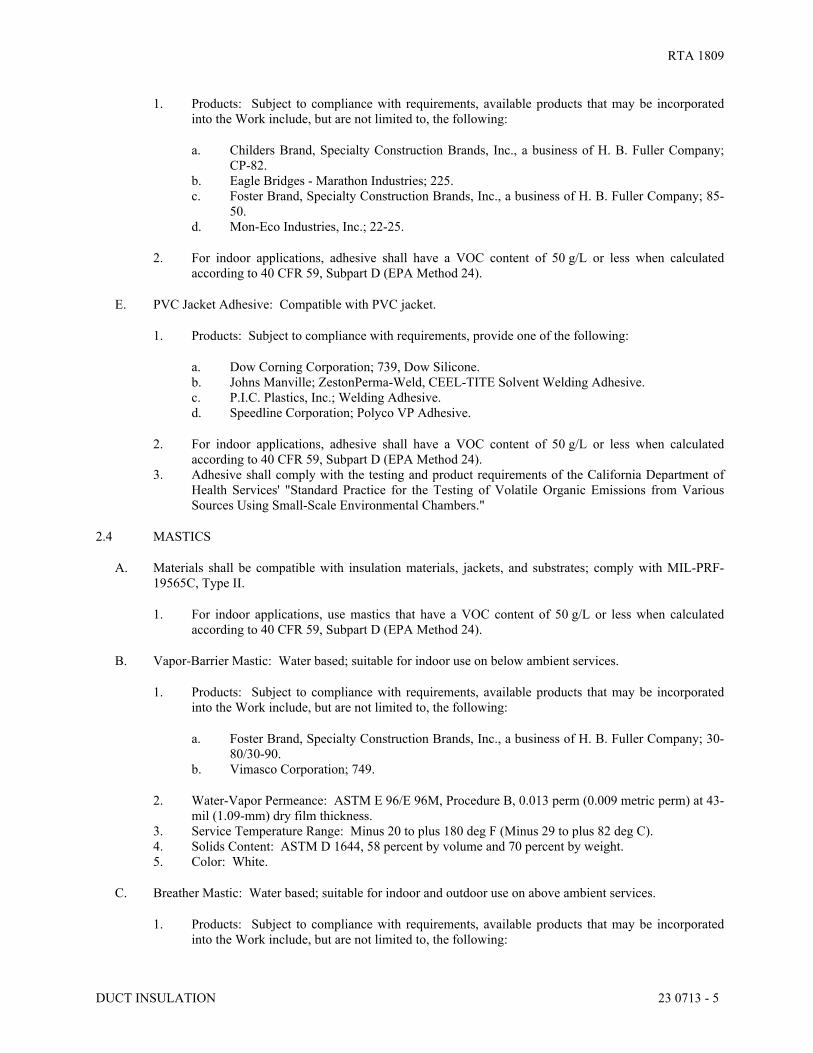
RTA 1809
DUCT INSULATION 23 0713 - 5
1. Products: Subject to compliance with requirements, available products that may be incorporated into the Work include, but are not limited to, the following:
a. Childers Brand, Specialty Construction Brands, Inc., a business of H. B. Fuller Company; CP-82.
b. Eagle Bridges - Marathon Industries; 225.c. Foster Brand, Specialty Construction Brands, Inc., a business of H. B. Fuller Company; 85-
50.d. Mon-Eco Industries, Inc.; 22-25.
2. For indoor applications, adhesive shall have a VOC content of 50 g/L or less when calculated according to 40 CFR 59, Subpart D (EPA Method 24).
E. PVC Jacket Adhesive: Compatible with PVC jacket.
1. Products: Subject to compliance with requirements, provide one of the following:
a. Dow Corning Corporation; 739, Dow Silicone.b. Johns Manville; ZestonPerma-Weld, CEEL-TITE Solvent Welding Adhesive.c. P.I.C. Plastics, Inc.; Welding Adhesive.d. Speedline Corporation; Polyco VP Adhesive.
2. For indoor applications, adhesive shall have a VOC content of 50 g/L or less when calculated according to 40 CFR 59, Subpart D (EPA Method 24).
3. Adhesive shall comply with the testing and product requirements of the California Department of Health Services' "Standard Practice for the Testing of Volatile Organic Emissions from Various Sources Using Small-Scale Environmental Chambers."
2.4 MASTICS
A. Materials shall be compatible with insulation materials, jackets, and substrates; comply with MIL-PRF-19565C, Type II.
1. For indoor applications, use mastics that have a VOC content of 50 g/L or less when calculated according to 40 CFR 59, Subpart D (EPA Method 24).
B. Vapor-Barrier Mastic: Water based; suitable for indoor use on below ambient services.
1. Products: Subject to compliance with requirements, available products that may be incorporated into the Work include, but are not limited to, the following:
a. Foster Brand, Specialty Construction Brands, Inc., a business of H. B. Fuller Company; 30-80/30-90.
b. Vimasco Corporation; 749.
2. Water-Vapor Permeance: ASTM E 96/E 96M, Procedure B, 0.013 perm (0.009 metric perm) at 43-mil (1.09-mm) dry film thickness.
3. Service Temperature Range: Minus 20 to plus 180 deg F (Minus 29 to plus 82 deg C).4. Solids Content: ASTM D 1644, 58 percent by volume and 70 percent by weight.5. Color: White.
C. Breather Mastic: Water based; suitable for indoor and outdoor use on above ambient services.
1. Products: Subject to compliance with requirements, available products that may be incorporated into the Work include, but are not limited to, the following:

RTA 1809
DUCT INSULATION 23 0713 - 6
a. Childers Brand, Specialty Construction Brands, Inc., a business of H. B. Fuller Company; CP-10.
b. Eagle Bridges - Marathon Industries; 550.c. Foster Brand, Specialty Construction Brands, Inc., a business of H. B. Fuller Company; 46-
50.d. Mon-Eco Industries, Inc.; 55-50.e. Vimasco Corporation; WC-1/WC-5.
2. Water-Vapor Permeance: ASTM F 1249, 1.8 perms (1.2 metric perms) at 0.0625-inch (1.6-mm) dry film thickness.
3. Service Temperature Range: Minus 20 to plus 180 deg F (Minus 29 to plus 82 deg C).4. Solids Content: 60 percent by volume and 66 percent by weight.5. Color: White.
2.5 LAGGING ADHESIVES
A. Description: Comply with MIL-A-3316C, Class I, Grade A and shall be compatible with insulation materials, jackets, and substrates.
1. For indoor applications, use lagging adhesives that have a VOC content of 50 g/L or less when calculated according to 40 CFR 59, Subpart D (EPA Method 24).
2. Products: Subject to compliance with requirements, available products that may be incorporated into the Work include, but are not limited to, the following:
a. Childers Brand, Specialty Construction Brands, Inc., a business of H. B. Fuller Company; CP-50 AHV2.
b. Foster Brand, Specialty Construction Brands, Inc., a business of H. B. Fuller Company; 30-36.
c. Vimasco Corporation; 713 and 714.
3. Fire-resistant, water-based lagging adhesive and coating for use indoors to adhere fire-resistant lagging cloths over duct insulation.
4. Service Temperature Range: 0 to plus 180 deg F (Minus 18 to plus 82 deg C).5. Color: White.
2.6 SEALANTS
A. FSK and Metal Jacket Flashing Sealants:
1. Products: Subject to compliance with requirements, available products that may be incorporated into the Work include, but are not limited to, the following:
a. Childers Brand, Specialty Construction Brands, Inc., a business of H. B. Fuller Company; CP-76.
b. Eagle Bridges - Marathon Industries; 405.c. Foster Brand, Specialty Construction Brands, Inc., a business of H. B. Fuller Company; 95-
44.d. Mon-Eco Industries, Inc.; 44-05.
2. Materials shall be compatible with insulation materials, jackets, and substrates.3. Fire- and water-resistant, flexible, elastomeric sealant.4. Service Temperature Range: Minus 40 to plus 250 deg F (Minus 40 to plus 121 deg C).5. Color: Aluminum.6. For indoor applications, sealants shall have a VOC content of 420 g/L or less when calculated
according to 40 CFR 59, Subpart D (EPA Method 24).

RTA 1809
DUCT INSULATION 23 0713 - 7
B. ASJ Flashing Sealants, and Vinyl and PVC Jacket Flashing Sealants:
1. Products: Subject to compliance with requirements, available products that may be incorporated into the Work include, but are not limited to, the following:
a. Childers Brand, Specialty Construction Brands, Inc., a business of H. B. Fuller Company; CP-76.
2. Materials shall be compatible with insulation materials, jackets, and substrates.3. Fire- and water-resistant, flexible, elastomeric sealant.4. Service Temperature Range: Minus 40 to plus 250 deg F (Minus 40 to plus 121 deg C).5. Color: White.6. For indoor applications, sealants shall have a VOC content of 420 g/L or less when calculated
according to 40 CFR 59, Subpart D (EPA Method 24).
2.7 FACTORY-APPLIED JACKETS
A. Comply with the following:
1. FSK Jacket: Aluminum-foil, fiberglass-reinforced scrim with kraft-paper backing; complying with ASTM C 1136, Type II.
2.8 FIELD-APPLIED JACKETS
A. Field-applied jackets shall comply with ASTM C 921, Type I, unless otherwise indicated.
B. Metal Jacket:
1. Products: Subject to compliance with requirements, available products that may be incorporated into the Work include, but are not limited to, the following:
a. Childers Brand, Specialty Construction Brands, Inc., a business of H. B. Fuller Company; Metal Jacketing Systems.
b. ITW Insulation Systems; Aluminum and Stainless Steel Jacketing.c. RPR Products, Inc.; Insul-Mate.
2. Aluminum Jacket: Comply with ASTM B 209 (ASTM B 209M), Alloy 3003, 3005, 3105, or 5005, Temper H-14.
a. Sheet and roll stock ready for shop or field sizing or Factory cut and rolled to size.b. Finish and thickness are indicated in field-applied jacket schedules.c. Moisture Barrier for Outdoor Applications: 3-mil- (0.075-mm-) thick, heat-bonded
polyethylene and kraft paper
2.9 TAPES
A. FSK Tape: Foil-face, vapor-retarder tape matching factory-applied jacket with acrylic adhesive; complying with ASTM C 1136.
1. Products: Subject to compliance with requirements, available products that may be incorporated into the Work include, but are not limited to, the following:
a. ABI, Ideal Tape Division; 491 AWF FSK.b. Avery Dennison Corporation, Specialty Tapes Division; Fasson 0827.c. Compac Corporation; 110 and 111.
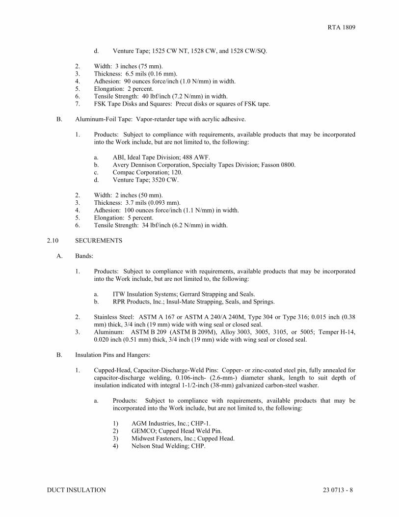
RTA 1809
DUCT INSULATION 23 0713 - 8
d. Venture Tape; 1525 CW NT, 1528 CW, and 1528 CW/SQ.
2. Width: 3 inches (75 mm).3. Thickness: 6.5 mils (0.16 mm).4. Adhesion: 90 ounces force/inch (1.0 N/mm) in width.5. Elongation: 2 percent.6. Tensile Strength: 40 lbf/inch (7.2 N/mm) in width.7. FSK Tape Disks and Squares: Precut disks or squares of FSK tape.
B. Aluminum-Foil Tape: Vapor-retarder tape with acrylic adhesive.
1. Products: Subject to compliance with requirements, available products that may be incorporated into the Work include, but are not limited to, the following:
a. ABI, Ideal Tape Division; 488 AWF.b. Avery Dennison Corporation, Specialty Tapes Division; Fasson 0800.c. Compac Corporation; 120.d. Venture Tape; 3520 CW.
2. Width: 2 inches (50 mm).3. Thickness: 3.7 mils (0.093 mm).4. Adhesion: 100 ounces force/inch (1.1 N/mm) in width.5. Elongation: 5 percent.6. Tensile Strength: 34 lbf/inch (6.2 N/mm) in width.
2.10 SECUREMENTS
A. Bands:
1. Products: Subject to compliance with requirements, available products that may be incorporated into the Work include, but are not limited to, the following:
a. ITW Insulation Systems; Gerrard Strapping and Seals.b. RPR Products, Inc.; Insul-Mate Strapping, Seals, and Springs.
2. Stainless Steel: ASTM A 167 or ASTM A 240/A 240M, Type 304 or Type 316; 0.015 inch (0.38 mm) thick, 3/4 inch (19 mm) wide with wing seal or closed seal.
3. Aluminum: ASTM B 209 (ASTM B 209M), Alloy 3003, 3005, 3105, or 5005; Temper H-14, 0.020 inch (0.51 mm) thick, 3/4 inch (19 mm) wide with wing seal or closed seal.
B. Insulation Pins and Hangers:
1. Cupped-Head, Capacitor-Discharge-Weld Pins: Copper- or zinc-coated steel pin, fully annealed for capacitor-discharge welding, 0.106-inch- (2.6-mm-) diameter shank, length to suit depth of insulation indicated with integral 1-1/2-inch (38-mm) galvanized carbon-steel washer.
a. Products: Subject to compliance with requirements, available products that may be incorporated into the Work include, but are not limited to, the following:
1) AGM Industries, Inc.; CHP-1.2) GEMCO; Cupped Head Weld Pin.3) Midwest Fasteners, Inc.; Cupped Head.4) Nelson Stud Welding; CHP.

RTA 1809
DUCT INSULATION 23 0713 - 9
2. Self-Sticking-Base Insulation Hangers: Baseplate welded to projecting spindle that is capable of holding insulation, of thickness indicated, securely in position indicated when self-locking washer is in place. Comply with the following requirements:
a. Products: Subject to compliance with requirements, available products that may be incorporated into the Work include, but are not limited to, the following:
1) AGM Industries, Inc.; Tactoo Self-Adhering Insul-Hangers.2) GEMCO; Peel & Press.3) Midwest Fasteners, Inc.; Self Stick.
b. Baseplate: Galvanized carbon-steel sheet, 0.030 inch (0.76 mm) thick by 2 inches (50 mm) square.
c. Spindle: Copper- or zinc-coated, low-carbon steel, fully annealed, 0.106-inch- (2.6-mm-) diameter shank, length to suit depth of insulation indicated.
d. Adhesive-backed base with a peel-off protective cover.
3. Insulation-Retaining Washers: Self-locking washers formed from 0.016-inch- (0.41-mm-) thick, galvanized-steel sheet, with beveled edge sized as required to hold insulation securely in place but not less than 1-1/2 inches (38 mm) in diameter.
a. Products: Subject to compliance with requirements, available products that may be incorporated into the Work include, but are not limited to, the following:
1) AGM Industries, Inc.; RC-150.2) GEMCO; R-150.3) Midwest Fasteners, Inc.; WA-150.4) Nelson Stud Welding; Speed Clips.
b. Protect ends with capped self-locking washers incorporating a spring steel insert to ensure permanent retention of cap in exposed locations.
C. Staples: Outward-clinching insulation staples, nominal 3/4-inch- (19-mm-) wide, stainless steel or Monel.
D. Wire: 0.062-inch (1.6-mm) soft-annealed, stainless steel.
2.11 CORNER ANGLES
A. Aluminum Corner Angles: 0.040 inch (1.0 mm) thick, minimum 1 by 1 inch (25 by 25 mm), aluminum according to ASTM B 209 (ASTM B 209M), Alloy 3003, 3005, 3105, or 5005; Temper H-14.
B. Stainless-Steel Corner Angles: 0.024 inch (0.61 mm)thick, minimum 1 by 1 inch (25 by 25 mm), stainless steel according to ASTM A 167 or ASTM A 240/A 240M, Type 304 or Type 316.
PART 3 - EXECUTION
3.1 EXAMINATION
A. Examine substrates and conditions for compliance with requirements for installation tolerances and other conditions affecting performance of insulation application.
1. Verify that systems to be insulated have been tested and are free of defects.2. Verify that surfaces to be insulated are clean and dry.

RTA 1809
DUCT INSULATION 23 0713 - 10
B. Proceed with installation only after unsatisfactory conditions have been corrected.
3.2 PREPARATION
A. Surface Preparation: Clean and dry surfaces to receive insulation. Remove materials that will adversely affect insulation application.
3.3 GENERAL INSTALLATION REQUIREMENTS
A. For ducts mounted on trapeze hangers or channel supports, provide rigid foam type insulation inserts at hanger contact points to prevent crushing of insulation.
B. Install insulation materials, accessories, and finishes with smooth, straight, and even surfaces; free of voids throughout the length of ducts and fittings.
C. Install insulation materials, vapor barriers or retarders, jackets, and thicknesses required for each item of duct system as specified in insulation system schedules.
D. Install accessories compatible with insulation materials and suitable for the service. Install accessories that do not corrode, soften, or otherwise attack insulation or jacket in either wet or dry state.
E. Install insulation with longitudinal seams at top and bottom of horizontal runs.
F. Install multiple layers of insulation with longitudinal and end seams staggered.
G. Keep insulation materials dry during application and finishing.
H. Install insulation with tight longitudinal seams and end joints. Bond seams and joints with adhesive recommended by insulation material manufacturer.
I. Install insulation with least number of joints practical.
J. Where vapor barrier is indicated, seal joints, seams, and penetrations in insulation at hangers, supports, anchors, and other projections with vapor-barrier mastic.
1. Install insulation continuously through hangers and around anchor attachments.2. For insulation application where vapor barriers are indicated, extend insulation on anchor legs from
point of attachment to supported item to point of attachment to structure. Taper and seal ends at attachment to structure with vapor-barrier mastic.
3. Install insert materials and install insulation to tightly join the insert. Seal insulation to insulation inserts with adhesive or sealing compound recommended by insulation material manufacturer.
K. Apply adhesives, mastics, and sealants at manufacturer's recommended coverage rate and wet and dry film thicknesses.
L. Install insulation with factory-applied jackets as follows:
1. Draw jacket tight and smooth.2. Cover circumferential joints with 3-inch- (75-mm-) wide strips, of same material as insulation
jacket. Secure strips with adhesive and outward clinching staples along both edges of strip, spaced 4 inches (100 mm)o.c.
3. Overlap jacket longitudinal seams at least 1-1/2 inches (38 mm). Clean and dry surface to receive self-sealing lap. Staple laps with outward clinching staples along edge at 2 inches (50 mm)o.c.
a. For below ambient services, apply vapor-barrier mastic over staples.

RTA 1809
DUCT INSULATION 23 0713 - 11
4. Cover joints and seams with tape, according to insulation material manufacturer's written instructions, to maintain vapor seal.
5. Where vapor barriers are indicated, apply vapor-barrier mastic on seams and joints and at ends adjacent to duct flanges and fittings.
M. Cut insulation in a manner to avoid compressing insulation more than 75 percent of its nominal thickness.
N. Finish installation with systems at operating conditions. Repair joint separations and cracking due to thermal movement.
O. Repair damaged insulation facings by applying same facing material over damaged areas. Extend patches at least 4 inches (100 mm) beyond damaged areas. Adhere, staple, and seal patches similar to butt joints.
3.4 PENETRATIONS
A. Insulation Installation at Roof Penetrations: Install insulation continuously through roof penetrations.
1. Seal penetrations with flashing sealant.2. For applications requiring only indoor insulation, terminate insulation above roof surface and seal
with joint sealant. For applications requiring indoor and outdoor insulation, install insulation for outdoor applications tightly joined to indoor insulation ends. Seal joint with joint sealant.
3. Extend jacket of outdoor insulation outside roof flashing at least 2 inches (50 mm) below top of roof flashing.
4. Seal jacket to roof flashing with flashing sealant.
B. Insulation Installation at Interior Wall and Partition Penetrations (That Are Not Fire Rated): Install insulation continuously through walls and partitions.
C. Insulation Installation at Fire-Rated Wall and Partition Penetrations: Terminate insulation at fire damper sleeves for fire-rated wall and partition penetrations. Externally insulate damper sleeves to match adjacent insulation and overlap duct insulation at least 2 inches (50 mm).
1. Comply with requirements in Division 07 Section "Penetration Firestopping" for firestopping and fire-resistive joint sealers.
D. Insulation Installation at Floor Penetrations:
1. Duct: For penetrations through fire-rated assemblies, terminate insulation at fire damper sleeves and externally insulate damper sleeve beyond floor to match adjacent duct insulation. Overlap damper sleeve and duct insulation at least 2 inches (50 mm).
2. Seal penetrations through fire-rated assemblies. Comply with requirements in Division 07 Section "Penetration Firestopping."
3.5 INSTALLATION OF FLEXIBLE ELASTOMERIC INSULATION
A. Seal longitudinal seams and end joints with manufacturer's recommended adhesive to eliminate openings in insulation that allow passage of air to surface being insulated.
3.6 INSTALLATION OF MINERAL-FIBER INSULATION
A. Blanket Insulation Installation on Ducts and Plenums: Secure with adhesive and insulation pins.
1. Apply adhesives according to manufacturer's recommended coverage rates per unit area, for 50 percent coverage of duct and plenum surfaces.
2. Apply adhesive to entire circumference of ducts and to all surfaces of fittings and transitions.

RTA 1809
DUCT INSULATION 23 0713 - 12
3. Install either capacitor-discharge-weld pins and speed washers or cupped-head, capacitor-discharge-weld pins on sides and bottom of horizontal ducts and sides of vertical ducts as follows:
a. On duct sides with dimensions 18 inches (450 mm) and smaller, place pins along longitudinal centerline of duct. Space 3 inches (75 mm) maximum from insulation end joints, and 16 inches (400 mm)o.c.
b. On duct sides with dimensions larger than 18 inches (450 mm), place pins 16 inches (400 mm)o.c. each way, and 3 inches (75 mm) maximum from insulation joints. Install additional pins to hold insulation tightly against surface at cross bracing.
c. Pins may be omitted from top surface of horizontal, rectangular ducts and plenums.d. Do not overcompress insulation during installation.e. Impale insulation over pins and attach speed washers.f. Cut excess portion of pins extending beyond speed washers or bend parallel with insulation
surface. Cover exposed pins and washers with tape matching insulation facing.
4. For ducts and plenums with surface temperatures below ambient, install a continuous unbroken vapor barrier. Create a facing lap for longitudinal seams and end joints with insulation by removing 2 inches (50 mm) from one edge and one end of insulation segment. Secure laps to adjacent insulation section with 1/2-inch (13-mm) outward-clinching staples, 1 inch (25 mm)o.c. Install vapor barrier consisting of factory- or field-applied jacket, adhesive, vapor-barrier mastic, and sealant at joints, seams, and protrusions.
a. Repair punctures, tears, and penetrations with tape or mastic to maintain vapor-barrier seal.b. Install vapor stops for ductwork and plenums operating below 50 deg F (10 deg C) at 18-
foot (5.5-m) intervals. Vapor stops shall consist of vapor-barrier mastic applied in a Z-shaped pattern over insulation face, along butt end of insulation, and over the surface. Cover insulation face and surface to be insulated a width equal to two times the insulation thickness, but not less than 3 inches (75 mm).
5. Overlap unfaced blankets a minimum of 2 inches (50 mm) on longitudinal seams and end joints. At end joints, secure with steel bands spaced a maximum of 18 inches (450 mm)o.c.
6. Install insulation on rectangular duct elbows and transitions with a full insulation section for each surface. Install insulation on round and flat-oval duct elbows with individually mitered gores cut to fit the elbow.
7. Insulate duct stiffeners, hangers, and flanges that protrude beyond insulation surface with 6-inch- (150-mm-) wide strips of same material used to insulate duct. Secure on alternating sides of stiffener, hanger, and flange with pins spaced 6 inches (150 mm)o.c.
B. Board and Pipe and Tank Insulation Installation on Ducts and Plenums: Secure with adhesive and insulation pins.
1. Apply adhesives according to manufacturer's recommended coverage rates per unit area, for 50 percent coverage of duct and plenum surfaces.
2. Apply adhesive to entire circumference of ducts and to all surfaces of fittings and transitions.3. Install either capacitor-discharge-weld pins and speed washers or cupped-head, capacitor-
discharge-weld pins on sides and bottom of horizontal ducts and sides of vertical ducts as follows:
a. On duct sides with dimensions 18 inches (450 mm) and smaller, place pins along longitudinal centerline of duct. Space 3 inches (75 mm) maximum from insulation end joints, and 16 inches (400 mm)o.c.
b. On duct sides with dimensions larger than 18 inches (450 mm), space pins 16 inches (400 mm)o.c. each way, and 3 inches (75 mm) maximum from insulation joints. Install additional pins to hold insulation tightly against surface at cross bracing.
c. Pins may be omitted from top surface of horizontal, rectangular ducts and plenums.d. Do not overcompress insulation during installation.

RTA 1809
DUCT INSULATION 23 0713 - 13
e. Cut excess portion of pins extending beyond speed washers or bend parallel with insulation surface. Cover exposed pins and washers with tape matching insulation facing.
4. For ducts and plenums with surface temperatures below ambient, install a continuous unbroken vapor barrier. Create a facing lap for longitudinal seams and end joints with insulation by removing 2 inches (50 mm) from one edge and one end of insulation segment. Secure laps to adjacent insulation section with 1/2-inch (13-mm) outward-clinching staples, 1 inch (25 mm)o.c. Install vapor barrier consisting of factory- or field-applied jacket, adhesive, vapor-barrier mastic, and sealant at joints, seams, and protrusions.
a. Repair punctures, tears, and penetrations with tape or mastic to maintain vapor-barrier seal.b. Install vapor stops for ductwork and plenums operating below 50 deg F (10 deg C) at 18-
foot (5.5-m) intervals. Vapor stops shall consist of vapor-barrier mastic applied in a Z-shaped pattern over insulation face, along butt end of insulation, and over the surface. Cover insulation face and surface to be insulated a width equal to two times the insulation thickness, but not less than 3 inches (75 mm).
5. Install insulation on rectangular duct elbows and transitions with a full insulation section for each surface. Groove and score insulation to fit as closely as possible to outside and inside radius of elbows. Install insulation on round and flat-oval duct elbows with individually mitered gores cut to fit the elbow.
6. Insulate duct stiffeners, hangers, and flanges that protrude beyond insulation surface with 6-inch- (150-mm-) wide strips of same material used to insulate duct. Secure on alternating sides of stiffener, hanger, and flange with pins spaced 6 inches (150 mm)o.c.
3.7 FIELD-APPLIED JACKET INSTALLATION
A. Where metal jackets are indicated, install with 2-inch (50-mm) overlap at longitudinal seams and end joints. Overlap longitudinal seams arranged to shed water. Seal end joints with weatherproof sealant recommended by insulation manufacturer. Secure jacket with stainless-steel bands 12 inches (300 mm)o.c. and at end joints.
3.8 FIRE-RATED INSULATION SYSTEM INSTALLATION
A. Where fire-rated insulation system is indicated, secure system to ducts and duct hangers and supports to maintain a continuous fire rating.
B. Insulate duct access panels and doors to achieve same fire rating as duct.
C. Install firestopping at penetrations through fire-rated assemblies. Fire-stop systems are specified in Division 07 Section "Penetration Firestopping."
3.9 DUCT INSULATION SCHEDULE, GENERAL
A. Plenums and Ducts Requiring Insulation:
1. Indoor, exposed exhaust between isolation damper and penetration of building exterior.2. Outdoor, exposed exhaust.
3.10 INDOOR DUCT AND PLENUM INSULATION SCHEDULE
A. In tight spots (such as, at duct crossing points with piping or other ducts, or where ducts pass under deep joists) primary air and supply air duct insulation shall be either of the following:
1. Flexible Elastomeric: 1/2 inch (13 mm) thick.

RTA 1809
DUCT INSULATION 23 0713 - 14
2. Polyolefin: 1/2 inch (13 mm) thick.
B. Exposed, exhaust-air duct insulation from exhaust plenum to exhaust air motor operated damper shall be the following:
1. Mineral-Fiber Board: 1-1/2 inches (38 mm) thick and 3-lb/cu. ft. (48-kg/cu. m) nominal density.
C. Exposed, outside-air duct insulation from energy recovery units to air handling units shall be the following:
1. Mineral-Fiber Board: 1-1/2 inches (38 mm) thick and 3-lb/cu. ft. (48-kg/cu. m) nominal density.
D. Exposed, single wall exhaust and outside-air plenum insulation shall be the following:
1. Mineral-Fiber Board: 1-1/2 inches (38 mm) thick and 3-lb/cu. ft. (48-kg/cu. m) nominal density.
3.11 OUTDOOR DUCT INSULATION SCHEDULE
A. Crown the insulation on top of the ducts to prevent ponding.
B. Exposed, Type I, commercial kitchen hood exhaust duct insulation shall be the following:
1. Mineral-Fiber Board: 2- inches (50 mm) thick and 6-lb/cu. ft. (96-kg/cu. m) nominal density, with field-applied jacket.
3.12 OUTDOOR, FIELD-APPLIED JACKET SCHEDULE
A. Install jacket over insulation material. For insulation with factory-applied jacket, install the field-applied jacket over the factory-applied jacket.
B. Type I, commercial kitchen hood exhaust duct:
1. Aluminum, Smooth: 0.024 inch (0.61 mm) thick.
END OF SECTION 230713

METAL DUCTS 23 3113 - 1
SECTION 23 3113 - METAL DUCTS
PART 1 - GENERAL
1.1 RELATED DOCUMENTS
A. Drawings and general provisions of the Contract, including General and Supplementary Conditions and Division 01 Specification Sections, apply to this Section.
1.2 SUMMARY
A. Section Includes:
1. Single-wall rectangular ducts and fittings.2. Sheet metal materials.3. Sealants and gaskets.4. Hangers and supports.
B. Install duct access doors where indicated in Specification Section "AIR DUCT ACCESSORIES".
C. Install duct accessories (such as turning vanes, access doors, dampers, automatic control dampers, sound traps, grilles and diffusers, etc.) furnished under other sections of the Specification in duct system.
D. Install stainless steel duct accessories in stainless steel duct systems. Provide stainless steel duct support systems (such as strap hangers, support plates, etc.).
1.3 PERFORMANCE REQUIREMENTS
A. Duct construction, including sheet metal thicknesses, seam and joint construction, reinforcements, and hangers and supports, shall comply with SMACNA's "HVAC Duct Construction Standards - Metal and Flexible" and performance requirements and design criteria indicated in "Duct Schedule" Article.
B. Airstream Surfaces: Surfaces in contact with the airstream shall comply with requirements in ASHRAE 62.1.
1.4 ACTION SUBMITTALS
A. Product Data: For each type of the following products:
1. Liners and adhesives.2. Sealants and gaskets.
B. Samples: Submit the following samples of fittings for medium and/or high pressure duct:
1. Single wall round and oval duct 45 deg. laterals.
C. Samples must be approved by the Engineer before shop drawings will be reviewed. Samples, if approved, will be delivered to the job site and used to evaluate duct and fittings delivered to the project site. All duct and fittings, whether round or oval, must equal or exceed the quality of the samples specifically submitted and approved. Duct and fittings that are not comparable in quality to the samples will be rejected and must be removed from the project site.
D. Welding certificates.
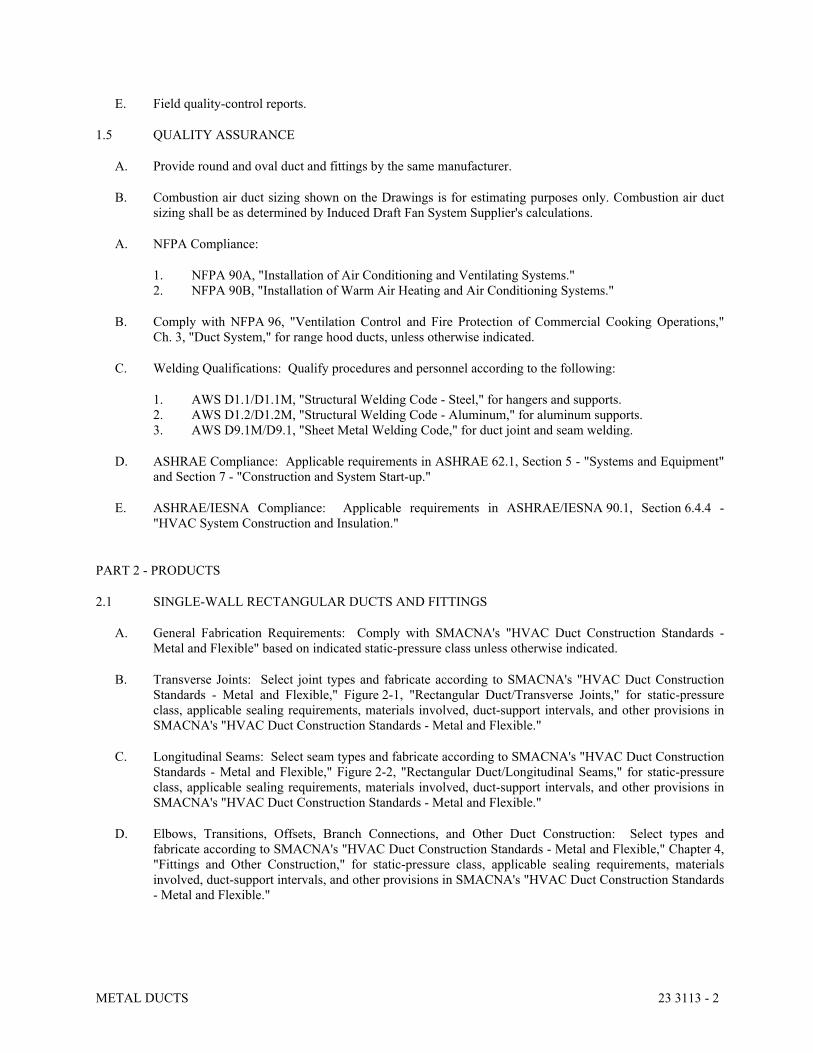
METAL DUCTS 23 3113 - 2
E. Field quality-control reports.
1.5 QUALITY ASSURANCE
A. Provide round and oval duct and fittings by the same manufacturer.
B. Combustion air duct sizing shown on the Drawings is for estimating purposes only. Combustion air duct sizing shall be as determined by Induced Draft Fan System Supplier's calculations.
A. NFPA Compliance:
1. NFPA 90A, "Installation of Air Conditioning and Ventilating Systems."2. NFPA 90B, "Installation of Warm Air Heating and Air Conditioning Systems."
B. Comply with NFPA 96, "Ventilation Control and Fire Protection of Commercial Cooking Operations," Ch. 3, "Duct System," for range hood ducts, unless otherwise indicated.
C. Welding Qualifications: Qualify procedures and personnel according to the following:
1. AWS D1.1/D1.1M, "Structural Welding Code - Steel," for hangers and supports.2. AWS D1.2/D1.2M, "Structural Welding Code - Aluminum," for aluminum supports.3. AWS D9.1M/D9.1, "Sheet Metal Welding Code," for duct joint and seam welding.
D. ASHRAE Compliance: Applicable requirements in ASHRAE 62.1, Section 5 - "Systems and Equipment" and Section 7 - "Construction and System Start-up."
E. ASHRAE/IESNA Compliance: Applicable requirements in ASHRAE/IESNA 90.1, Section 6.4.4 - "HVAC System Construction and Insulation."
PART 2 - PRODUCTS
2.1 SINGLE-WALL RECTANGULAR DUCTS AND FITTINGS
A. General Fabrication Requirements: Comply with SMACNA's "HVAC Duct Construction Standards - Metal and Flexible" based on indicated static-pressure class unless otherwise indicated.
B. Transverse Joints: Select joint types and fabricate according to SMACNA's "HVAC Duct Construction Standards - Metal and Flexible," Figure 2-1, "Rectangular Duct/Transverse Joints," for static-pressure class, applicable sealing requirements, materials involved, duct-support intervals, and other provisions in SMACNA's "HVAC Duct Construction Standards - Metal and Flexible."
C. Longitudinal Seams: Select seam types and fabricate according to SMACNA's "HVAC Duct Construction Standards - Metal and Flexible," Figure 2-2, "Rectangular Duct/Longitudinal Seams," for static-pressure class, applicable sealing requirements, materials involved, duct-support intervals, and other provisions in SMACNA's "HVAC Duct Construction Standards - Metal and Flexible."
D. Elbows, Transitions, Offsets, Branch Connections, and Other Duct Construction: Select types and fabricate according to SMACNA's "HVAC Duct Construction Standards - Metal and Flexible," Chapter 4, "Fittings and Other Construction," for static-pressure class, applicable sealing requirements, materials involved, duct-support intervals, and other provisions in SMACNA's "HVAC Duct Construction Standards - Metal and Flexible."

METAL DUCTS 23 3113 - 3
2.2 FLEXIBLE DUCTS:
A. Manufacturers: Subject to compliance with requirements, provide products from one of the following:
1. Clevepak Corporation, Clevaflex Division2. Flexmaster, USA, Inc.3. Hart & Cooley, Inc.
B. Flexible ducts shall be a factory-fabricated assembly consisting of an all-aluminum flexible duct, insulation and an outer moisture barrier.
C. Ducts shall be of single-ply aluminum, closely corrugated for strength, folded flat, and knurled to insure air-tightness.
D. A l-l/2" thick insulating blanket of glass wool with a polyethylene moisture barrier shall encase the ducts.
E. Assembly shall have a flame spread of not over 25, a smoke developed rate of not over 50 and shall comply with U.L. Standard No. UL l8l.
F. Ducts shall be suitable for use at up to l0 inches W.G. static pressure.
G. Flexible duct insulation may be omitted on flexible ducts in return and exhaust air systems.
2.3 FLEXIBLE DUCT CONNECTORS:
A. Clamps: Stainless-steel band with cadmium-plated hex screw to tighten band with a worm-gear action in sizes 3 through 18 inches (75 through 460 mm), to suit duct size.
2.4 SHEET METAL MATERIALS
A. General Material Requirements: Comply with SMACNA's "HVAC Duct Construction Standards - Metal and Flexible" for acceptable materials, material thicknesses, and duct construction methods unless otherwise indicated. Sheet metal materials shall be free of pitting, seam marks, roller marks, stains, discolorations, and other imperfections.
B. Galvanized Sheet Steel: Comply with ASTM A 653/A 653M.
1. Galvanized Coating Designation: G90 (Z275).2. Finishes for Surfaces Exposed to View: Mill phosphatized.
C. Carbon-Steel Sheets: Comply with ASTM A 1008/A 1008M, with oiled, matte finish for exposed ducts.
D. Stainless-Steel Sheets: Comply with ASTM A 480/A 480M, Type 304 or 316, as indicated in the "Duct Schedule" Article; cold rolled, annealed, sheet. Exposed surface finish shall be No. 2B, No. 2D, No. 3, or No. 4 as indicated in the "Duct Schedule" Article.
E. Reinforcement Shapes and Plates: ASTM A 36/A 36M, steel plates, shapes, and bars; black and galvanized.
1. Where black- and galvanized-steel shapes and plates are used to reinforce aluminum ducts, isolate the different metals with butyl rubber, neoprene, or EPDM gasket materials.
F. Tie Rods: Galvanized steel, 1/4-inch (6-mm) minimum diameter for lengths 36 inches (900 mm) or less; 3/8-inch (10-mm) minimum diameter for lengths longer than 36 inches (900 mm).
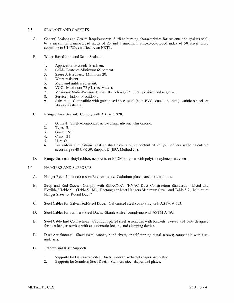
METAL DUCTS 23 3113 - 4
2.5 SEALANT AND GASKETS
A. General Sealant and Gasket Requirements: Surface-burning characteristics for sealants and gaskets shall be a maximum flame-spread index of 25 and a maximum smoke-developed index of 50 when tested according to UL 723; certified by an NRTL.
B. Water-Based Joint and Seam Sealant:
1. Application Method: Brush on.2. Solids Content: Minimum 65 percent.3. Shore A Hardness: Minimum 20.4. Water resistant.5. Mold and mildew resistant.6. VOC: Maximum 75 g/L (less water).7. Maximum Static-Pressure Class: 10-inch wg (2500 Pa), positive and negative.8. Service: Indoor or outdoor.9. Substrate: Compatible with galvanized sheet steel (both PVC coated and bare), stainless steel, or
aluminum sheets.
C. Flanged Joint Sealant: Comply with ASTM C 920.
1. General: Single-component, acid-curing, silicone, elastomeric.2. Type: S.3. Grade: NS.4. Class: 25.5. Use: O.6. For indoor applications, sealant shall have a VOC content of 250 g/L or less when calculated
according to 40 CFR 59, Subpart D (EPA Method 24).
D. Flange Gaskets: Butyl rubber, neoprene, or EPDM polymer with polyisobutylene plasticizer.
2.6 HANGERS AND SUPPORTS
A. Hanger Rods for Noncorrosive Environments: Cadmium-plated steel rods and nuts.
B. Strap and Rod Sizes: Comply with SMACNA's "HVAC Duct Construction Standards - Metal and Flexible," Table 5-1 (Table 5-1M), "Rectangular Duct Hangers Minimum Size," and Table 5-2, "Minimum Hanger Sizes for Round Duct."
C. Steel Cables for Galvanized-Steel Ducts: Galvanized steel complying with ASTM A 603.
D. Steel Cables for Stainless-Steel Ducts: Stainless steel complying with ASTM A 492.
E. Steel Cable End Connections: Cadmium-plated steel assemblies with brackets, swivel, and bolts designed for duct hanger service; with an automatic-locking and clamping device.
F. Duct Attachments: Sheet metal screws, blind rivets, or self-tapping metal screws; compatible with duct materials.
G. Trapeze and Riser Supports:
1. Supports for Galvanized-Steel Ducts: Galvanized-steel shapes and plates.2. Supports for Stainless-Steel Ducts: Stainless-steel shapes and plates.

METAL DUCTS 23 3113 - 5
PART 3 - EXECUTION
3.1 DUCT INSTALLATION
A. Drawing plans, schematics, and diagrams indicate general location and arrangement of duct system. Indicated duct locations, configurations, and arrangements were used to size ducts and calculate friction loss for air-handling equipment sizing and for other design considerations. Install duct systems as indicated unless deviations to layout are approved on Shop Drawings and Coordination Drawings.
B. Install ducts according to SMACNA's "HVAC Duct Construction Standards - Metal and Flexible" unless otherwise indicated.
C. Do not apply duct sealant to interior surfaces of ductwork.
D. Do not install straight tees in medium or high pressure ductwork.
E. Do not install conical tees in medium or high pressure ductwork except where specifically shown on the Drawings.
F. Do not install pleated or adjustable elbows in medium or high pressure ductwork.
G. Do not install mitered elbows without turning vanes in medium or high pressure ductwork. Do not install mitered elbows with turning vanes in medium or high pressure ductwork except where specifically shown on the Drawings.
H. Do not install mitered elbows of any angle in rectangular ductwork except at points specifically shown on the Drawings. Use smooth radius elbows.
I. Do not install mitered elbows, (with or without turning vanes) in return or exhaust duct systems except where specifically shown on the Drawings. Use 90o mitered elbows with turning vanes only in low pressure supply air ductwork.
J. Where radius elbows with R/D ratio of 1.5 cannot be installed due to space limitations, use a radius elbow with an R/D of 1.0 or as specifically shown on the Drawings.
K. Do not substitute a square elbow with turning vanes for a radius elbow.
L. Where square elbows with turning vanes (in supply ductwork) are shown on the Drawings, use square elbows with turning vanes. Do not substitute a radius elbow for a square elbow with turning vanes.
M. Where square elbows with turning vanes are shown on the Drawings in return or exhaust ductwork, provide minimum size 12"x12" access doors in bottom of elbows, upstream and downstream of turning vanes, for access to clean vanes.
N. Where radius elbows with R/D ratios of other than 1.5 are shown on the Drawings, install radius elbows with the R/D ratio indicated on the Drawings.
O. Install Combination (heeled) tees in medium or high pressure ductwork where specifically shown on the Drawings.
P. Install round and flat-oval ducts in maximum practical lengths.
Q. Install ducts with fewest possible joints.
METAL DUCTS 23 3113 - 6
R. Install factory- or shop-fabricated fittings for changes in direction, size, and shape and for branch connections.
S. Unless otherwise indicated, install ducts vertically and horizontally, and parallel and perpendicular to building lines.
T. Install ducts close to walls, overhead construction, columns, and other structural and permanent enclosure elements of building.
U. Install ducts with a clearance of 1 inch (25 mm), plus allowance for insulation thickness.
V. Route ducts to avoid passing through transformer vaults and electrical equipment rooms and enclosures.
W. Where ducts pass through non-fire-rated interior partitions and exterior walls and are exposed to view, cover the opening between the partition and duct or duct insulation with sheet metal flanges of same metal thickness as the duct. Overlap openings on four sides by at least 1-1/2 inches (38 mm).
X. Where ducts pass through fire-rated interior partitions and exterior walls, install fire dampers. Comply with requirements in Division 23 Section "Air Duct Accessories" for fire and smoke dampers.
Y. Protect duct interiors from moisture, construction debris and dust, and other foreign materials. Comply with SMACNA's "IAQ Guidelines for Occupied Buildings Under Construction," Appendix G, "Duct Cleanliness for New Construction Guidelines."
3.2 INSTALLATION OF EXPOSED DUCTWORK
A. Protect ducts exposed in finished spaces from being dented, scratched, or damaged.
B. Trim duct sealants flush with metal. Create a smooth and uniform exposed bead. Do not use two-part tape sealing system.
C. Grind welds to provide smooth surface free of burrs, sharp edges, and weld splatter. When welding stainless steel with a No. 3 or 4 finish, grind the welds flush, polish the exposed welds, and treat the welds to remove discoloration caused by welding.
D. Maintain consistency, symmetry, and uniformity in the arrangement and fabrication of fittings, hangers and supports, duct accessories, and air outlets.
E. Repair or replace damaged sections and finished work that does not comply with these requirements.
3.3 FLEXIBLE DUCTS, INSTALLATION REQUIREMENTS
A. For any duct run using flexible ductwork, do not exceed 3'-0" extended length unless shown otherwise on the drawings.
B. Minimum bend radius shall be l-l/2 times the duct diameter.
C. Flexible duct shall not have more than 90 deg. total deflection unless shown otherwise.
3.4 DUCT SEALING
A. Seal ducts according to the “DUCT SEALING, TESTING AND LEAKAGE TABLES” at the end of this specification section.
METAL DUCTS 23 3113 - 7
B. In round and oval ductwork with pressure classifications greater than 3 inches, apply duct sealant continuously over male end of slip joints before assembly. Wipe away any excess sealant protruding inside duct after assembly. Then fasten joint with sheet metal screws and coat entire joint, including screws, with sealant.
1. At Installer's option, the "hardcast" tape and sealant system may be used to seal duct joints instead of the method specified in the paragraph above.
C. Seal corners of rectangular ductwork completely with sealant, especially corners of "Ductmate" and other types of flanged joints. If holes at corners are too large to permit sealant, then remake joint.
D. Seal top joints of rectangular ductwork. If ductwork is to be installed too close to building substrate to permit sealing these joints after installation, then seal joints before ductwork is raised into place.
E. Do not apply duct sealant to interior surfaces of ductwork.
F. Seal ducts before external insulation is applied.
3.5 HANGER AND SUPPORT INSTALLATION
A. Comply with SMACNA's "HVAC Duct Construction Standards - Metal and Flexible," Chapter 5, "Hangers and Supports."
B. Building Attachments: Concrete inserts, powder-actuated fasteners, or structural-steel fasteners appropriate for construction materials to which hangers are being attached.
1. Where practical, install concrete inserts before placing concrete.2. Install powder-actuated concrete fasteners after concrete is placed and completely cured.3. Use powder-actuated concrete fasteners for standard-weight aggregate concretes or for slabs more
than 4 inches (100 mm) thick.4. Do not use powder-actuated concrete fasteners for lightweight-aggregate concretes or for slabs less
than 4 inches (100 mm) thick.5. Do not use powder-actuated concrete fasteners for seismic restraints.
C. Hanger Spacing: Comply with SMACNA's "HVAC Duct Construction Standards - Metal and Flexible," Table 5-1 (Table 5-1M), "Rectangular Duct Hangers Minimum Size," and Table 5-2, "Minimum Hanger Sizes for Round Duct," for maximum hanger spacing; install hangers and supports within 24 inches (610 mm) of each elbow and within 48 inches (1200 mm) of each branch intersection.
D. Hangers Exposed to View: Threaded rod and angle or channel supports.
E. Support vertical ducts with steel angles or channel secured to the sides of the duct with welds, bolts, sheet metal screws, or blind rivets; support at each floor and at a maximum intervals of 16 feet (5 m).
F. Do not use strap hangers on oval ductwork. Use double trapeze type with top and bottom bracing.
G. Do not penetrate duct wall with screws to attach hangers to medium and/or high pressure ductwork.
H. Install upper attachments to structures. Select and size upper attachments with pull-out, tension, and shear capacities appropriate for supported loads and building materials where used.
I. Do not use metal decking for suspension of ductwork and accessories. Hang items from top member of joist or provide additional structure to span between top members if needed.

METAL DUCTS 23 3113 - 8
3.6 CONNECTIONS
A. Make connections to equipment with flexible connectors complying with Division 23 Section "Air Duct Accessories."
B. Comply with SMACNA's "HVAC Duct Construction Standards - Metal and Flexible" for branch, outlet and inlet, and terminal unit connections.
C. Make connections to grilles, registers and diffusers as detailed on the Drawings. Do not deviate from these details.
1. Provide the boxes with turning vanes or mitred round elbows with turning vanes for supply diffusers. Make branch connections into the sides of these boxes as detailed.
2. Provide full size sheet metal boxes over return and exhaust grilles and registers. Make the boxes the minimum height shown on the Drawings. If no minimum height is given, then the minimum height shall be 10 inches. Make branch connections into the sides of these boxes as detailed.
D. Install volume dampers in branch ducts at the locations shown on the Drawings. Do not install the dampers at the branch duct connection points to the grilles and diffusers.
E. Provide volume dampers behind register or diffuser faces only behind sidewall outlets, and only where specifically indicated on the Drawings.
3.7 PAINTING
A. Paint interior of metal ducts that are visible through registers and grilles and that do not have duct liner. Apply one coat of flat, black, latex paint over a compatible galvanized-steel primer. Paint materials and application requirements are specified in Division 09 painting Sections.
3.8 FIELD QUALITY CONTROL
A. Perform tests and inspections.
B. Leakage Tests:
1. All new ductwork shall be pressure tested by a testing and balancing agency. See Specification Section " TESTING, ADJUSTING AND BALANCING FOR HVAC".
2. Test pressures and allowable leakage rates shall be according to the “DUCT SEALING, TESTING AND LEAKAGE TABLES” at the end of this specification section.
3. Testing shall be conducted before external insulation is applied and before ducts are connected.4. Make arrangements with the testing and balancing agency for coordinating the duct testing and for
isolating the duct systems into the lengths necessary for proper testing. 5. Perform any sheet metal work required by the testing and balancing agency for proper testing. 6. Repair and/or replace any defective joints, seams, or any leakage problems found in the ductwork
testing.7. Disassemble, reassemble, and seal segments of systems to accommodate leakage testing and for
compliance with test requirements.8. Do not pressurize systems above test pressure.9. Give seven days' advance notice for testing.10. After the system is balanced, repair and/or replace any defective joints, seams, or any leakage
problems where the balanced air flow is more than 10 per cent less than design air flow. In particular, check for leaks at duct connections to grilles and diffusers.

METAL DUCTS 23 3113 - 9
C. Duct System Cleanliness Tests:
1. Visually inspect duct system to ensure that no visible contaminants are present.2. Test sections of metal duct system, chosen randomly by Owner, for cleanliness according to
"Vacuum Test" in NADCA ACR, "Assessment, Cleaning and Restoration of HVAC Systems."
a. Acceptable Cleanliness Level: Net weight of debris collected on the filter media shall not exceed 0.75 mg/100 sq. cm.
D. Duct system will be considered defective if it does not pass tests and inspections.
E. Prepare test and inspection reports.
3.9 DUCT CLEANING
A. Clean duct systems before testing, adjusting, and balancing.
B. Use service openings for entry and inspection.
1. Create new openings and install access panels appropriate for duct static-pressure class if required for cleaning access. Provide insulated panels for insulated or lined duct. Patch insulation and liner as recommended by duct liner manufacturer. Comply with Division 23 Section "Air Duct Accessories" for access panels and doors.
2. Disconnect and reconnect flexible ducts as needed for cleaning and inspection.3. Remove and reinstall ceiling to gain access during the cleaning process.
C. Particulate Collection and Odor Control:
1. When venting vacuuming system inside the building, use HEPA filtration with 99.97 percent collection efficiency for 0.3-micron-size (or larger) particles.
2. When venting vacuuming system to outdoors, use filter to collect debris removed from HVAC system, and locate exhaust downwind and away from air intakes and other points of entry into building.
D. Clean the following components by removing surface contaminants and deposits:
1. Air outlets and inlets (registers, grilles, and diffusers).2. Supply, return, and exhaust fans including fan housings, plenums (except ceiling supply and return
plenums), scrolls, blades or vanes, shafts, baffles, dampers, and drive assemblies.3. Air-handling unit internal surfaces and components including mixing box, coil section, air wash
systems, spray eliminators, condensate drain pans, humidifiers and dehumidifiers, filters and filter sections, and condensate collectors and drains.
4. Coils and related components.5. Return-air ducts, dampers, actuators, and turning vanes except in ceiling plenums and mechanical
equipment rooms.6. Supply-air ducts, dampers, actuators, and turning vanes.7. Dedicated exhaust and ventilation components and makeup air systems.
E. Mechanical Cleaning Methodology:
1. Clean metal duct systems using mechanical cleaning methods that extract contaminants from within duct systems and remove contaminants from building.
2. Use vacuum-collection devices that are operated continuously during cleaning. Connect vacuum device to downstream end of duct sections so areas being cleaned are under negative pressure.

METAL DUCTS 23 3113 - 10
3. Use mechanical agitation to dislodge debris adhered to interior duct surfaces without damaging integrity of metal ducts, duct liner, or duct accessories.
4. Clean coils and coil drain pans according to NADCA 1992. Keep drain pan operational. Rinse coils with clean water to remove latent residues and cleaning materials; comb and straighten fins.
5. Provide drainage and cleanup for wash-down procedures.6. Antimicrobial Agents and Coatings: Apply EPA-registered antimicrobial agents if fungus is
present. Apply antimicrobial agents according to manufacturer's written instructions after removal of surface deposits and debris.
3.10 START UP
A. Air Balance: Comply with requirements in Division 23 Section "Testing, Adjusting, and Balancing for HVAC."
3.11 DUCT SCHEDULE
A. Fabricate ducts with galvanized sheet steel except as otherwise indicated and as follows:
B. Refer to " DUCT SEALING, TESTING AND LEAKAGE TABLES" for duct systems, seal class, leakage class and test pressures. Pressure classes shall be the same as the test pressures listed in the "TEST PRESSURE" Column.
Ductwork in Conditioned Spaces
Duct System Seal Class
Leakage Class
Test Pressure “ W.G.
Allowable Leakage CFM/100SF
Exhaust duct - round B 6 3 12
Exhaust duct - rectangular B 12 3 24
END OF SECTION 233113

RTA 1809
HVAC POWER VENTILATORS 23 3423 - 1
SECTION 23 3423 - HVAC POWER VENTILATORS
PART 1 - GENERAL
1.1 RELATED DOCUMENTS
A. Drawings and general provisions of the Contract, including General and Supplementary Conditions and Division 01 Specification Sections, apply to this Section.
1.2 SUMMARY
A. Section Includes:
1. Centrifugal roof ventilators.
1.3 PERFORMANCE REQUIREMENTS
A. Project Altitude: Base fan-performance ratings on actual Project site elevations.
B. Operating Limits: Classify according to AMCA 99.
1.4 ACTION SUBMITTALS
A. Product Data: For each type of product indicated. Include rated capacities, operating characteristics, and furnished specialties and accessories. Also include the following:
1. Certified fan performance curves with system operating conditions indicated.2. Certified fan sound-power ratings.3. Motor ratings and electrical characteristics, plus motor and electrical accessories.4. Material thickness and finishes, including color charts.5. Dampers, including housings, linkages, and operators.6. Roof curbs.7. Fan speed controllers.
B. Shop Drawings: Include plans, elevations, sections, details, and attachments to other work.
1. Detail equipment assemblies and indicate dimensions, weights, loads, required clearances, method of field assembly, components, and location and size of each field connection.
2. Wiring Diagrams: For power, signal, and control wiring.
1.5 INFORMATIONAL SUBMITTALS
A. Coordination Drawings: Reflected ceiling plans and other details, drawn to scale, on which the following items are shown and coordinated with each other, using input from Installers of the items involved:
1. Roof framing and support members relative to duct penetrations.2. Ceiling suspension assembly members.3. Size and location of initial access modules for acoustical tile.

RTA 1809
HVAC POWER VENTILATORS 23 3423 - 2
4. Ceiling-mounted items including light fixtures, diffusers, grilles, speakers, sprinklers, access panels, and special moldings.
B. Field quality-control reports.
1.6 CLOSEOUT SUBMITTALS
A. Operation and Maintenance Data: For power ventilators to include in emergency, operation, and maintenance manuals.
1.7 MAINTENANCE MATERIAL SUBMITTALS
A. Furnish extra materials that match products installed and that are packaged with protective covering for storage and identified with labels describing contents.
1. Belts: One set(s) for each belt-driven unit.
1.8 QUALITY ASSURANCE
A. Electrical Components, Devices, and Accessories: Listed and labeled as defined in NFPA 70, by a qualified testing agency, and marked for intended location and application.
B. AMCA Compliance: Fans shall have AMCA-Certified performance ratings and shall bear the AMCA-Certified Ratings Seal.
C. UL Standards: Power ventilators shall comply with UL 705. Power ventilators for use for restaurant kitchen exhaust shall also comply with UL 762.
1.9 COORDINATION
A. Coordinate size and location of structural-steel support members.
B. Coordinate sizes and locations of concrete bases with actual equipment provided.
C. Coordinate sizes and locations of roof curbs, equipment supports, and roof penetrations with actual equipment provided.
PART 2 - PRODUCTS
2.1 CENTRIFUGAL ROOF VENTILATORS
A. Manufacturers: Subject to compliance with requirements, available manufacturers offering products that may be incorporated into the Work include, but are not limited to, the following:
A. Basis-of-Design Product: Subject to compliance with requirements, provide product indicated on Drawings or comparable product by one of the following:
1. Acme Engineering & Manufacturing Corporation.2. Greenheck Fan Corporation.

RTA 1809
HVAC POWER VENTILATORS 23 3423 - 3
3. Loren Cook Company.
B. Housing: Removable, spun-aluminum, dome top and outlet baffle; square, one-piece, aluminum base with venturi inlet cone.
1. Upblast Units: Provide spun-aluminum discharge baffle to direct discharge air upward, with rain and snow drains and grease collector.
2. Hinged Subbase: Galvanized-steel hinged arrangement permitting service and maintenance.
C. Fan Wheels: Aluminum hub and wheel with backward-inclined blades.
D. Belt Drives:
1. Resiliently mounted to housing.2. Fan Shaft: Turned, ground, and polished steel; keyed to wheel hub.3. Shaft Bearings: Permanently lubricated, permanently sealed, self-aligning ball bearings.4. Pulleys: Cast-iron, adjustable-pitch motor pulley.5. Fan and motor isolated from exhaust airstream.
E. Accessories:
1. Variable-Speed Controller: Solid-state control to reduce speed from 100 to less than 50 percent.2. Disconnect Switch: Nonfusible type, with thermal-overload protection mounted outside fan
housing, factory wired through an internal aluminum conduit.3. Bird Screens: Removable, 1/2-inch (13-mm) mesh, aluminum or brass wire.4. Dampers: Counterbalanced, parallel-blade, backdraft dampers mounted in curb base; factory set
to close when fan stops.5. Motorized Dampers: Parallel-blade dampers mounted in curb base with electric actuator; wired to
close when fan stops.
F. Roof Curbs: Galvanized steel; mitered and welded corners; 1-1/2-inch- (40-mm-) thick, rigid, fiberglass insulation adhered to inside walls; and 1-1/2-inch (40-mm) wood nailer. Size as required to suit roof opening and fan base.
1. Configuration: Built-in raised cant and mounting flange.2. Overall Height: 12 inches (300 mm).3. Sound Curb: Curb with sound-absorbing insulation.4. Pitch Mounting: Manufacture curb for roof slope.5. Metal Liner: Galvanized steel.6. Mounting Pedestal: Galvanized steel with removable access panel.7. Vented Curb: Unlined with louvered vents in vertical sides.
G. Capacities and Characteristics:
1. See Schedules on drawings.
2.2 MOTORS
A. Comply with NEMA designation, temperature rating, service factor, enclosure type, and efficiency requirements for motors specified in Division 23 Section "Common Motor Requirements for HVAC Equipment."

RTA 1809
HVAC POWER VENTILATORS 23 3423 - 4
1. Motor Sizes: Minimum size as indicated. If not indicated, large enough so driven load will not require motor to operate in service factor range above 1.0.
2. Controllers, Electrical Devices, and Wiring: Comply with requirements for electrical devices and connections specified in Division 26 Sections.
B. Enclosure Type: Totally enclosed, fan cooled.
2.3 SOURCE QUALITY CONTROL
A. Certify sound-power level ratings according to AMCA 301, "Methods for Calculating Fan Sound Ratings from Laboratory Test Data." Factory test fans according to AMCA 300, "Reverberant Room Method for Sound Testing of Fans." Label fans with the AMCA-Certified Ratings Seal.
B. Certify fan performance ratings, including flow rate, pressure, power, air density, speed of rotation, and efficiency by factory tests according to AMCA 210, "Laboratory Methods of Testing Fans for Aerodynamic Performance Rating." Label fans with the AMCA-Certified Ratings Seal.
PART 3 - EXECUTION
3.1 INSTALLATION
A. Install power ventilators level and plumb.
B. Secure roof-mounted fans to roof curbs with cadmium-plated hardware. See Division 07 Section "Roof Accessories" for installation of roof curbs.
C. Ceiling Units: Suspend units from structure; use steel wire or metal straps.
D. Install units with clearances for service and maintenance.
E. Label units according to requirements specified in Division 23 Section "Identification for HVAC Piping and Equipment."
3.2 CONNECTIONS
A. Duct installation and connection requirements are specified in other Division 23 Sections. Drawings indicate general arrangement of ducts and duct accessories. Make final duct connections with flexible connectors. Flexible connectors are specified in Division 23 Section "Air Duct Accessories."
B. Install ducts adjacent to power ventilators to allow service and maintenance.
C. Ground equipment according to Division 26 Section "Grounding and Bonding for Electrical Systems."
D. Connect wiring according to Division 26 Section "Low-Voltage Electrical Power Conductors and Cables."
3.3 FIELD QUALITY CONTROL
A. Perform tests and inspections.

RTA 1809
HVAC POWER VENTILATORS 23 3423 - 5
1. Manufacturer's Field Service: Engage a factory-authorized service representative to inspect components, assemblies, and equipment installations, including connections, and to assist in testing.
B. Tests and Inspections:
1. Verify that shipping, blocking, and bracing are removed.2. Verify that unit is secure on mountings and supporting devices and that connections to ducts and
electrical components are complete. Verify that proper thermal-overload protection is installed in motors, starters, and disconnect switches.
3. Verify that cleaning and adjusting are complete.4. Disconnect fan drive from motor, verify proper motor rotation direction, and verify fan wheel free
rotation and smooth bearing operation. Reconnect fan drive system, align and adjust belts, and install belt guards.
5. Adjust belt tension.6. Adjust damper linkages for proper damper operation.7. Verify lubrication for bearings and other moving parts.8. Verify that manual and automatic volume control and fire and smoke dampers in connected
ductwork systems are in fully open position.9. Disable automatic temperature-control operators, energize motor and adjust fan to indicated rpm,
and measure and record motor voltage and amperage.10. Shut unit down and reconnect automatic temperature-control operators.11. Remove and replace malfunctioning units and retest as specified above.
C. Test and adjust controls and safeties. Replace damaged and malfunctioning controls and equipment.
D. Prepare test and inspection reports.
3.4 ADJUSTING
A. Adjust damper linkages for proper damper operation.
B. Adjust belt tension.
C. Comply with requirements in Division 23 Section "Testing, Adjusting, and Balancing for HVAC" for testing, adjusting, and balancing procedures.
D. Replace fan and motor pulleys as required to achieve design airflow.
E. Lubricate bearings.
END OF SECTION 23 3423

RTA 1809
GENERAL ELECTRICAL PROVISIONS 26 0000 - 1
DIVISION 26 – ELECTRICAL
SECTION 26 0000 – GENERAL ELECTRICAL PROVISIONS
PART 1 - GENERAL
1.1 GENERAL
A. The General Conditions, Special Conditions, Supplemental Conditions, Instructions to Bidders, and other Contract Documents apply to this branch of the work as well as to the other branches.
B. The Contractor shall familiarize himself with the work of all other trades, general type construction, and the relationship of his work to other sections. He shall examine all working drawings, specifications and conditions affecting his work. The Contractor shall visit the premises and thoroughly familiarize himself with all details of the work and working conditions, verify all dimensions in the field and advise the Engineer of any discrepancy before fabricating or performing any work.
C. The work shall include complete testing of all equipment, conduit and wiring at the completion of the work and making any minor connection changes or adjustments necessary for the proper functioning of the system and equipment.
D. Perform any necessary temporary work during construction.
E. Work under this section shall conform to governing codes, ordinances and regulations of the City, County and State.
F. The Contractor shall be responsible for any errors in fabrication, for the correct fitting, installation and erection of the various electrical systems.
1.2 SCOPE
A. Furnish and install all wiring devices and equipment, etc., unless otherwise indicated, for the complete electrical systems. It is the intent that the entire electrical work and all electrical systems shall be complete in every respect and that all outlets, receptacles, fixtures, motors, equipment, devices, etc., shown, noted, or required shall be completely connected from source of power to final connection, ready for satisfactory operation.
1.3 ELECTRICAL MATERIALS
A. It is the intent of these specifications that the conductive materials used in the manufacture of, but not limited to, the following types of equipment be of copper construction:1. Electrical Power Conductors and Cables (all voltages)
1.4 PROTECTION
A. All work, equipment and materials shall be protected at all times. All conduit openings shall be closed with caps or plugs during construction. All equipment and accessories shall be tightly covered and protected against dirt, water or other injury during the period of construction.
RTA 1809
GENERAL ELECTRICAL PROVISIONS 26 0000 - 2
1.5 AUTOMATIC TEMPERATURE AND ASSOCIATED SYSTEMS CONTROLS
A. All wiring associated with the automatic temperature controls system and all associated conduit not specifically designated to be provided shall be included by others and specified under division of these specifications including motor starter interlock wiring.
1.6 EQUIPMENT FURNISHED BY OTHERS
A. It shall be the responsibility of this Contractor to check voltage and current ratings of motors, relays, starters, switches, etc., of equipment furnished by others not connected under this section of the specifications. Nominal motor voltage ratings should be as follows:
1. For connection to 480V system – NEMA 460 volts 2. For connection to 208V system - NEMA 200 volts. 3. For connection to 110 volt system - NEMA 115 volt.
B. Motors not conforming to these ratings shall be called to the attention of the related subcontractor and the Owner/Architect.
1.7 EQUIPMENT INSTALLATION INSTRUCTIONS
A. Install electrical conduit, wiring and equipment in strict accordance with manufacturer's recommendations. Provide equipment accessories necessary for proper operation or recommended by the manufacturer, even if such accessories are not shown on the drawings or mentioned in the specifications.
1.8 INSTALLATION OF EQUIPMENT
A. All appliances, materials and equipment shall be installed and connected in accordance with the best engineering practice and in accordance with manufacturers' instructions and recommendations. All electrical connections, etc., recommended by the manufacturer or required for proper operation shall be furnished and installed complete.
1.9 EQUIPMENT CONNECTIONS
A. Make connections to equipment furnished by others whenever such equipment is shown on any part of the drawings or mentioned in any section of the specifications.
B. Verify equipment locations and the sizes, number, locations, and types of connections to be made before installation of any such equipment.
1.10 OPENINGS
A. The Contractor under this Division shall be responsible for the openings he may require in floors, walls or ceilings of any type construction whether or not shown on the Architectural and/or Structural Drawings.
B. Openings that have been shown on the Architectural and/or Structural Drawings will be provided under other Divisions; however, the responsibility for the correct size and location of such openings shall be that of the Contractor under this Division.

RTA 1809
GENERAL ELECTRICAL PROVISIONS 26 0000 - 3
C. Openings that have not been shown on the Architectural and/or Structural Drawings shall be provided by the Contractor under this Division as directed by the Architect.
1.11 FIRE BARRIER PENETRATION SEALS:
A. Provide seals for any opening through any walls, floors, or ceilings used as passage for electrical components such as conduit, cabling, etc.
B. General: Provide manufacturer's standard fire-stopping sealant, with accessory materials, having fire-resistance ratings as established by testing identical assemblies per ASTM E 8l4 by Underwriters' Laboratories, Inc. or other testing and inspecting agency acceptable to authorities having jurisdiction. Sealant shall provide protection equal or exceeding the fire resistance rating of fire rated walls, partitions, ceilings or floors. Use two-part or one part sealants as required to meet required fire resistance ratings.
C. Foamed-In-Place Fire-Stopping Sealant: Two-part, foamed-in-place, silicone sealant formulated for use in a through-penetration fire-stop system for filling openings around cables, conduit, pipes and similar penetrations through walls and floors.
D. One-Part Fire-Stopping Sealant: One part elastomeric sealant formulated for use in a through-penetration fire-stop system for sealing openings around cables, conduit, pipes and similar penetrations through walls and floors.
E. Available Products: Subject to compliance with requirements, products which may be incorporated in the Work include, but are not limited to, the following:
F. Products: Subject to compliance with requirements, provide one of the following:
1. Foamed-in-Place Fire-Stopping Sealant:
a. "Dow Corning Fire Stop Foam"; Dow Corning Corp. b. "Pensil 85l"; General Electric Co.
2. One-Part Fire-Stopping Sealant: a. "Dow Corning Fire Stop Sealant"; Dow Corning Corp. b. "3M Fire Barrier Caulk CP-25"; Electrical Products Div./3M. c. "RTV 7403"; General Electric Co. d. "Fyre Putty"; Standard Oil Engineered Materials Co.
G. Installation of Fire-Stopping Sealant: Install sealant, including forming, packing, and other accessory materials to fill openings around mechanical and electrical services penetrating floors and walls to provide fire-stops with fire resistance ratings indicated for floor or wall assembly in which penetration occurs. Comply with installation requirements established by testing and inspecting agency.
1.12 SINGULAR NUMBER
A. In all cases where a device or piece of equipment is referred to in the singular number (such as a light fixture, etc.), it is intended that such reference shall apply to as many such items as are required to complete the installation.
1.13 CONNECTION TO EXISTING ELECTRICAL SYSTEMS
A. The Contractor under this Division shall make all necessary electrical connections to all undisturbed existing electrical systems, as shown on the Drawings and/or required for their proper operation with the new system.

RTA 1809
GENERAL ELECTRICAL PROVISIONS 26 0000 - 4
1.14 SPECIAL NOTE
A. All openings in electrical equipment, enclosures, cabinets, outlet and junction boxes shall be by means of standard knockouts or shall be sawed or drilled. The use of a cutting torch is prohibited.
1.15 EQUIPMENT IDENTIFICATION
A. The Contractor for this Division shall furnish and install on all electrical equipment such as switches, starters, panelboards, etc., a nameplate giving its name and function.
B. Nameplates shall be engraved bakelite (white letters on black background) and shall be equal to Seton Nameplate, C. H. Hanson or Identifications.
1.16 MOTOR PROTECTION INFORMATION
A. The Contractor for this Division shall provide the following information for each motor installed on this project, regardless of the supplying Contractor:
1. Motor full load current 2. Motor starter heater size - where applicable 3. Fuse size
B. This information shall be provided in tabulation form before final payment will be made to the Contractor.
1.17 EQUIVALENT MATERIAL AND EQUIPMENT
A. Where equipment is approved which requires different arrangement of connections from those shown, it shall be the responsibility of the Contractor to install the equipment to operate properly and in harmony with the intent of the Drawings and Specifications, and to make all changes in the work required by the different arrangement of connections.
1.18 PERMITS, CODES AND APPROVALS
A. Permits
1. All permits necessary for the complete Electrical systems shall be obtained by the Contractor for Division 26 from the authorities governing such work. The cost of all permits shall be borne by this Contractor.
B. Codes and Rules and Regulations
1. The minimum standard for all electrical work shall be the latest revision of the National Electrical Code. Whenever and wherever state and/or local laws and/or regulations require a higher standard than the current National Electrical Code, then these laws and/or regulations shall be followed.
C. Approvals
1. All work must be approved by the Architect /Engineer and the Owner before final payment will be made.

RTA 1809
GENERAL ELECTRICAL PROVISIONS 26 0000 - 5
1.19 INSPECTIONS
A. The Contractor under this Division shall furnish electrical inspection by the inspection agency having jurisdiction. The Electrical Inspector shall be notified in writing immediately upon the start of the work and a copy of the notice shall be sent to the Architect/Engineer. All costs incidental to the electrical inspection shall be borne by the Contractor for Division 26.
B. The inspection shall be scheduled for rough as well as finished work. The rough inspection shall be divided into as many inspections as may become necessary to cover all roughing-in. A punch list inspection shall be scheduled with a representative of the Architect /Engineer present. The punch list inspection shall be made with panelboard and junction box covers removed.
C. Before final acceptance, the Contractor for Division 26 shall furnish a Certificate of Final Approval by the Electrical Inspector to the Architect /Engineer and the Owner.
1.20 UL LISTINGS
A. Materials and appliances for the type for which there are Underwriters' Laboratories standard requirements listings and labels, shall have listing of Underwriters' Laboratories and shall be so labeled, or shall conform to their requirements, in which case certified statements to that effect shall be furnished by the manufacturer with a copy of an examination report by a recognized testing laboratory acceptable to the Engineer.
1.21 WORKMANSHIP
A. Competent workmen shall be employed on all phases of the work. Poor workmanship will be rejected and will constitute cause for removal of the individual performing the work.
1.22 COOPERATION WITH OTHER CONTRACTORS
A. Each Contractor shall demand and examine all Drawings and Specifications pertaining to the construction before installing the work described and shown under these Drawings and Specifications. Each Contractor shall cooperate with all other Contractors in locating piping, conduit, openings, chases and equipment in order to avoid conflict with any other Contractor's work. All work installed above a lay-in ceiling must be coordinated and installed so there is a minimum of 4 inches between the top of the ceiling grid and the bottom of the installation.
B. If any discrepancies occur between the accompanying Drawings and these Specifications and Drawings and Specifications covering other Contracts, each Contractor shall report such discrepancies to the Architect/Engineer far enough in advance so that a workable solution can be presented. No extra payment will be allowed for relocation of piping, ductwork, conduit and equipment not installed in accordance with the above instructions, and which interferes with work and equipment of other Contractors.
1.23 COORDINATION OF WORK ABOVE LAY-IN CEILING
A. All work installed above a lay-in ceiling must be coordinated and installed so there is a minimum of 4 inches between the top of the ceiling grid and the bottom of the installation. Installation shall not obstruct equipment access space or equipment removal space.

RTA 1809
GENERAL ELECTRICAL PROVISIONS 26 0000 - 6
1.24 MAINTAINING EXISTING FACILITIES
A. The existing services to and within the building shall be maintained during the construction without interruption, except for short periods of time that may be required to make changeover connections. The Architect /Engineer shall be notified in advance and an agreement reached as to when the connections are to be made and the length of time the particular facility will be out of service.
B. All temporary connections that may be necessary to continue these services shall be properly made and maintained in a safe and substantial manner until the permanent facilities are activated. Upon completion, remove all temporary work, and completely restore all areas that may be affected.
C. At any time the existing building facilities are interrupted, the Contractor shall work continuously until the permanent services are restored. The Contractor shall pay for all premium time necessary to comply with these requirements.
1.25 GUARANTY CERTIFICATES
A. Certificates of guaranty accompanying those items of mechanical and electrical equipment on which manufacturer's guarantees have been specified, or are normally provided, shall be completely executed by the Contractor and delivered to the Architect before completion of the work.
1.26 CLEANING
A. After the Architect /Engineer has completed examination, the Contractor shall remove all stickers, tags, etc., and shall thoroughly clean all equipment, fixtures and materials installed under his section of the work.
B. Surplus material, rubbish and equipment resulting from the work shall be removed from the building and premises by the respective Contractors upon completion of the work in accordance with the General Conditions.
1.27 WORKMANSHIP
A. Work shall be performed by mechanics skilled in their respective trades and shall present appearance typical of best trade practice. Work not installed in this manner shall be repaired, removed or replaced, or otherwise remedied as directed by the Architect/Engineer.
1.28 SUPERVISION
A. The Contractor shall personally supervise the work or have a competent superintendent, satisfactory to the Architect/Engineer and Owner on the work at all times during progress with full authority to act.
B. The Contractor shall lay out his work and be responsible for any necessary lines, levels, elevations and measurements. He must verify the figures shown on the drawings before laying out the work and will be held responsible for any error resulting from his failure to do so. Work at the site of the project shall be observed by the Architect/Engineer or his representative.
C. Final Inspection: At the time of final inspection of the work performed under this Contract, systems shall be complete in every respect and in perfect operating condition. Surplus materials of every character resulting from work of this section shall have been removed. Sanitary sewers shall be free from sand, silt

RTA 1809
GENERAL ELECTRICAL PROVISIONS 26 0000 - 7
or other obstructions. Any defect discovered in the utilities subsequent to this inspection shall have been corrected.
1.29 INTERPRETATIONS
A. Wherever in these Specifications, the term "General Contractor" is used, it shall be understood to mean the Contractor engaged in the general construction portion of the work. Similarly, wherever the "Heating and Air Conditioning Contractor," "Plumbing Contractor," "Sprinkler Contractor," or "Contractor for Division 26" is mentioned as such, it shall be understood to refer to the Contractor engaged in that particular branch of the work.
1. It shall also be clearly understood that all Contractors for all branches of the work shall cooperate with each other in the coordination of the construction.
2. It shall also be clearly understood that the entire construction is one responsibility and all Contractors for all branches of the work shall cooperate with each other in the coordination of the construction.
1.30 WORKING DRAWINGS
A. Scale of drawings is approximate. Do not scale the drawings to determine locations of electrical work. Exact locations, dimensions and elevations shall be governed by field conditions. Make field measurements of building before fabricating or installing equipment or materials.
B. Drawings are based on physical dimensions of one or more manufacturer's equipment. Other approved equipment shall be of such dimensions that it can be readily installed in available space, leaving ample clearance for proper maintenance.
C. Intent of drawings is to show systems and sizes. Drawings do not necessarily show all required offsets. Work shall be installed to conform with space limitations. Offsets, transitions, fittings, etc., shall be provided as part of the Contract where required to attain this objective.
1.31 ELECTRICAL DRAWINGS AND SPECIFICATIONS
A. The Drawings and Specifications are intended to cover all work enumerated under the respective headings. The Drawings are diagrammatic only. The Contractor shall not take advantage of conflict or error between the Drawings and Specifications, but shall request a clarification of such before making his proposal.
1.32 ARCHITECTURAL DRAWINGS AND SPECIFICATIONS
A. The Contractor shall refer to the Architectural and Structural Drawings and Specifications for the general construction of the building, for floor and ceiling heights, for location of walls, partitions, beams, etc., and shall be guided accordingly for the setting of all sleeves, inserts and equipment.
B. Under no circumstances shall a Contractor scale the Drawings for the location of equipment and work.
1.33 DISCREPANCIES
A. If any discrepancies occur between the accompanying Drawings and these Specifications and Drawings and Specifications covering other Contracts, report such discrepancies to the Architect/Engineer far

RTA 1809
GENERAL ELECTRICAL PROVISIONS 26 0000 - 8
enough in advance so that a workable solution can be presented. No extra payment will be allowed for relocation of piping, ductwork, conduit and equipment not installed in accordance with the above instructions, and which interferes with work and equipment of other Contractors.
1.34 SHOP DRAWINGS
A. Equipment and material shop drawings, catalog sheets and descriptive data shall be submitted, each with a cover sheet first listing the project name, the Contractors, Architect and Engineer, and date of submittal. Next the section of the Specifications shall be listed stating the section for which the equipment is being proposed. Next, outline equipment showing compliances to the specification requirements, such as capacities, special accessories, options, model, sizes, etc. Reverse side of cover sheet shall be left for Contractors' stamps showing review and space for Engineers' review stamp. Catalog sheets shall be marked showing equipment proposed.
B. Materials submitted without cover sheet or Contractor review stamp and without required information will be returned to the Contractor.
1.35 STRUCTURAL RESPONSIBILITY
A. The Contractor shall be responsible for properly shoring, bracing, supporting, etc., any existing and/or new construction to guard against cracking, settling, collapsing, displacing, or weakening. No structural member shall be cut or otherwise weakened in any manner without the written consent of the Architect/Engineer.
B. Any damage occurring to the existing and/or new structures, due to failure to exercise proper precautions or due to action of the elements, shall be promptly and properly made good to the satisfaction of the Owner or Architect/Engineer, without cost to either the Owner or the Architect/ Engineer.
1.36 ASBESTOS
A. If during the course of his work the Contractor observes the existence of asbestos, or asbestos-bearing materials, the Contractor shall immediately terminate further work on the project and notify the Owner of the condition. The Owner will, after consultation with the Engineer, determine a further course of action.
1.37 OWNER INSTRUCTION
A. Conduct a full-day walk-through instruction seminar for the Owner's personnel to be involved in the continued operation and maintenance of mechanical equipment and systems. Explain the identification system, operational diagrams, emergency and alarm provisions, sequencing requirements, seasonal provisions, security, safety, efficiency and similar features of the systems.
B. All training shall be video recorded for future use by the Owner in training new personnel.
1.38 ACCESS UNITS
A. General: The work of this article is limited to the provisions for access through other work for access to electrical work, and does not include internal access provisions (within the electrical work). In general and where possible, furnish or furnish-and-mount required access units in other trades' work prior to their work, so that cutting and patching for the subsequent installation of such access units will not be required. In occupied spaces, provide finished access units of the maximum concealment type, including locks

RTA 1809
GENERAL ELECTRICAL PROVISIONS 26 0000 - 9
where appropriate, and matching access units provided in the same expanse of finish (for non-mechanical access, if any).
B. The scope of access units to be furnished or provided as electrical work includes those units indicated on the electrical drawings or specified in Division 26 sections, and those additional units required for adequate access to electrical work and not shown or specified individually.
C. Access Doors: Standard welded-steel construction, 16-gage frames and 14 gage door panels, 175 degree concealed spring hinges, rust-inhibitive prime coat, flush cam lock (for screw-driver operation where keyed lock is not required), recessed to receive applied finish where applicable (such as in concealed spline ceilings).
D. Removable Access Plates: Where only hand access is sufficient, provide removable plate-type access unit, or minimum size which will facilitate the required access. Provide units of the type, style, design, material and finish appropriate for the location and exposure in each instance. In exposed surfaces of occupied spaces provide round plate units, flush floor units and frameless low-profile wall units, primed-for-paint in painted surfaces and polished chrome or stainless steel finish in other surfaces.
E. Access Thru Fire Rated Walls or Ceilings: Where access doors or plates are required in fire rated partitions or ceilings, provide U.L. listed "B" Label doors or plates rated for 1-1/2 hours. Furnish doors with automatic closers and key operated latches that latch automatically when door closes.
1.39 OWNER OCCUPANCY
A. Full Owner Occupancy: The Owner will occupy the site and building surrounding construction area during the entire construction period. Cooperate with the Owner during construction operations to minimize conflicts and facilitate Owner usage. Perform the Work to minimize interference with the Owner's operations. Perform portions of work on premium time if required to do so by the Owner.
1.40 PROVIDING AIRTIGHT SPACES
A. In rooms where room walls extend above ceiling to the floor or roof above, caulk around all new and existing penetrations through walls, ceilings, floors and/or roofs to make completely airtight rooms. Seal penetrations both above and below suspended ceilings. Seal any openings left by removal of any existing or new work. Caulking used shall be the same type as specified in the Architectural Specifications.
B. Patch around rough openings of penetrations to form a tight fit before caulking.
1.41 LINTELS:
A. General: Provide lintels for penetration of electrical systems through masonry walls if not provided elsewhere in these specifications. Lintels shall be type and size required to span the required openings.
B. Lintels will not be required for openings 16 inches length or less.
1.42 ELECTRICAL WORK IN EXISTING (RENOVATED) AREAS
A. Maintain and restore, if interrupted by removals or in path of new construction, all circuits, conduits and feeders passing through and serving undisturbed areas (shown or not shown).
RTA 1809
GENERAL ELECTRICAL PROVISIONS 26 0000 - 10
B. Install all new work as indicated. Flush outlet boxes may be reused if at proper height, location and in good condition. Existing concealed conduits may be reused if in good condition, circuitry shown on plans shall govern. All other materials removed shall be removed from the job site or turned over to the Owner.
C. Where any existing outlet (electric, telephone, nurse call, TV, etc.) is noted or required to be removed, the Contractor under this Division shall connect conduit, pull in new conductors and reconnect as required for feed-thru of circuits to ensure all circuits downstream from removed outlets will remain operational.
D. Before start of work, the Contractor shall check all existing devices, light fixtures and equipment that is noted or required to be reused, to satisfy himself that they are operating properly. Should any of the items not be operating, the Contractor shall report same to the Architect /Engineer, and await his directions. Contractors not complying with the above will be responsible for providing operational items as his expense.
E. Contractor shall make a complete survey of the existing building before bidding the project. Any conflicts between the plans and/or notes and existing conditions must be brought to the attention of the Architect/Engineer before bidding. If no questions and/or conflicts are brought to the attention of the Architect/Engineer, it will be assumed that the Contractor has completed the survey.
PART 2 - PRODUCTS
2.1 Not Applicable
PART 3 - EXECUTION
3.1 Not Applicable
END OF SECTION 26 0000

RTA 1809
SELECTIVE DEMOLITION 26 0411 - 1
SECTION 26 0411 - SELECTIVE DEMOLITION
PART 1 - GENERAL
1.1 RELATED DOCUMENTS
A. Drawings and general provisions of the Contract, including General and Supplementary Conditions and Division 01 Specification Sections, apply to this Section.
1.2 SUMMARY
A. Section Includes:
1. Demolition and removal of selected portions of building or systems.
2. Demolition and removal of selected site elements.
3. Salvage of existing items to be reused or recycled.
1.3 DEFINITIONS
A. Remove: Detach items from existing construction and legally dispose of them off-site unless indicated to be removed and salvaged or removed and reinstalled.
B. Remove and Salvage: Carefully detach from existing construction, in a manner to prevent damage, and deliver to Owner.
C. Remove and Reinstall: Detach items from existing construction, prepare for reuse, and reinstall where indicated.
D. Existing to Remain: Existing items of construction that are not to be permanently removed and that are not otherwise indicated to be removed, removed and salvaged, or removed and reinstalled.
1.4 MATERIALS OWNERSHIP
A. Unless otherwise indicated and as modified below, demolition waste becomes property of Contractor.
B. The Owner has the right to salvage any materials/equipment disconnected/removed by the Contractor. The Owner will coordinate with the Contractor to identify items to be salvaged. The Contractor will disconnect and remove these items, stockpile them in a mutually agreed location, and keep them in good condition. The Owner will remove these items from the stockpile location. Carefully salvage in a manner to prevent damage and promptly return to Owner. Items to be salvaged are noted on the electrical demolition drawings.
RTA 1809
SELECTIVE DEMOLITION 26 0411 - 2
1.5 INFORMATIONAL SUBMITTALS
A. Proposed Protection Measures: Submit report, including drawings, that indicates the measures proposed for protecting individuals and property, for environmental protection, for dust control, and for noise control. Indicate proposed locations and construction of barriers.
B. Schedule of Selective Demolition Activities: Indicate the following:
1. Detailed sequence of selective demolition and removal work, with starting and ending dates for each activity. Ensure Owner's on-site operations are uninterrupted.
2. Interruption of utility services. Indicate how long utility services will be interrupted.
3. Coordination for shutoff, capping, and continuation of utility services.
4. Use of elevator and stairs.
5. Coordination of Owner's continuing occupancy of portions of existing building and of Owner's partial occupancy of completed Work.
C. Inventory: Submit a list of items to be removed and salvaged and deliver to Owner prior to start of demolition.
D. Predemolition Photographs or Video: Submit before Work begins.
1.6 FIELD CONDITIONS
A. Owner will occupy portions of the building immediately adjacent to selective demolition area. Conduct selective demolition so Owner's operations will not be disrupted.
B. Conditions existing at time of inspection for bidding purpose will be maintained by Owner as far as practical.
C. Notify Engineer of discrepancies between existing conditions and Drawings before proceeding with selective demolition.
D. Hazardous Materials: It is not expected that hazardous materials will be encountered in the Work.
1. If suspected hazardous materials are encountered, do not disturb; immediately notify Architect and Owner. Hazardous materials will be removed by Owner under a separate contract.
E. Demolition and hauling equipment and other materials shall be of sizes that clear surfaces within spaces, areas, rooms, and openings, including temporary protection, by 12 inches or more.
F. Storage or sale of removed items or materials on-site is not permitted.

RTA 1809
SELECTIVE DEMOLITION 26 0411 - 3
G. Utility Service: Maintain existing utilities indicated to remain in service and protect them against damage during selective demolition operations.
1. Maintain fire-protection facilities in service during selective demolition operations.
1.7 WARRANTY
A. Existing Warranties: Remove, replace, patch, and repair materials and surfaces cut or damaged during selective demolition, by methods and with materials so as not to void existing warranties. Notify warrantor before proceeding.
PART 2 - PRODUCTS
2.1 PEFORMANCE REQUIREMENTS
A. Regulatory Requirements: Comply with governing EPA notification regulations before beginning selective demolition. Comply with hauling and disposal regulations of authorities having jurisdiction.
B. Standards: Comply with ANSI/ASSE A10.6 and NFPA 241.
PART 3 - EXECUTION
3.1 EXAMINATION
A. Verify that utilities have been disconnected and capped before starting selective demolition operations.
B. Review record documents of existing construction provided by Owner. Owner does not guarantee that existing conditions are same as those indicated in record documents.
C. Survey existing conditions and correlate with requirements indicated to determine extent of selective demolition required.
D. When unanticipated mechanical, electrical, or structural elements that conflict with intended function or design are encountered, investigate and measure the nature and extent of conflict. Promptly submit a written report to Engineer.
E. Survey of Existing Conditions: Record existing conditions by use of pre-construction video recordings.
3.2 UTILITY SERVICES AND MECHANICAL/ELECTRICAL SYSTEMS
A. Existing Services/Systems to Remain: Maintain services/systems indicated to remain and protect them against damage.
B. Existing Services/Systems to Be Removed, Relocated, or Abandoned: Locate, identify, disconnect, and seal or cap off indicated utility services and mechanical/electrical systems serving areas to be selectively demolished.

RTA 1809
SELECTIVE DEMOLITION 26 0411 - 4
1. Arrange to shut off indicated utilities with utility companies.
2. If services/systems are required to be removed, relocated, or abandoned, provide temporary services/systems that bypass area of selective demolition and that maintain continuity of services/systems to other parts of building.
3.3 PREPARATION
A. Site Access and Temporary Controls: Conduct selective demolition and debris-removal operations to ensure minimum interference with roads, streets, walks, walkways, and other adjacent occupied and used facilities.
B. Temporary Facilities: Provide temporary barricades and other protection required to prevent injury to people and damage to adjacent buildings and facilities to remain.
1. Provide protection to ensure safe passage of people around selective demolition area and to and from occupied portions of building.
2. Provide temporary weather protection, during interval between selective demolition of existing construction on exterior surfaces and new construction, to prevent water leakage and damage to structure and interior areas.
3. Protect walls, ceilings, floors, and other existing finish work that are to remain or that are exposed during selective demolition operations.
4. Cover and protect furniture, furnishings, and equipment that have not been removed.
3.4 SELECTIVE DEMOLITION, GENERAL
A. General: Demolish and remove existing construction only to the extent required by new construction and as indicated. Use methods required to complete the Work within limitations of governing regulations and as follows:
1. Proceed with selective demolition systematically
2. Neatly cut openings and holes plumb, square, and true to dimensions required. Use cutting methods least likely to damage construction to remain or adjoining construction. Use hand tools or small power tools designed for sawing or grinding, not hammering and chopping, to minimize disturbance of adjacent surfaces. Temporarily cover openings to remain.
3. Cut or drill from the exposed or finished side into concealed surfaces to avoid marring existing finished surfaces.
4. Do not use cutting torches.
5. Remove decayed, vermin-infested, or otherwise dangerous or unsuitable materials and promptly dispose of off-site.

RTA 1809
SELECTIVE DEMOLITION 26 0411 - 5
B. Removed and Salvaged Items:
1. Clean salvaged items.
2. Pack or crate items after cleaning. Identify contents of containers.
3. Store items in a secure area until delivery to Owner.
4. Transport items to Owner's storage area designated by Owner.
5. Protect items from damage during transport and storage.
C. Removed and Reinstalled Items:
1. Clean and repair items to functional condition adequate for intended reuse.
2. Pack or crate items after cleaning and repairing. Identify contents of containers.
3. Protect items from damage during transport and storage.
4. Reinstall items in locations indicated. Comply with installation requirements for new materials and equipment. Provide connections, supports, and miscellaneous materials necessary to make item functional for use indicated.
D. Existing Items to Remain: Protect construction indicated to remain against damage and soiling during selective demolition. When permitted by Engineer, items may be removed to a suitable, protected storage location during selective demolition and cleaned and reinstalled in their original locations after selective demolition operations are complete.
3.5 DISPOSAL OF DEMOLISHED MATERIALS
A. General: Except for items or materials indicated to be recycled, reused, salvaged, reinstalled, or otherwise indicated to remain Owner's property, remove demolished materials from Project site and legally dispose of them.
1. Do not allow demolished materials to accumulate on-site.
2. Remove and transport debris in a manner that will prevent spillage on adjacent surfaces and areas.
3. Remove debris from elevated portions of building by chute, hoist, or other device that will convey debris to grade level in a controlled descent.
B. Burning: Do not burn demolished materials.
C. Disposal: Transport demolished materials off Owner's property and legally dispose of them.
RTA 1809
SELECTIVE DEMOLITION 26 0411 - 6
3.6 CLEANING
A. Clean adjacent structures and improvements of dust, dirt, and debris caused by selective demolition operations. Return adjacent areas to condition existing before selective demolition operations began.
3.7 ELECTRICAL RELATED ABATEMENT PROCEDURES
A. Due to the likely presence of ballast containing PCB’s in existing light fixtures that are to be demolished, as well as mercury content in the fluorescent lamps, contractor is to assume that all existing-to-be-removed fluorescent fixtures contain such materials, and is to perform the following abatement procedures in accordance with all applicable Federal PCB and Mercury Abatement regulations.
B. Electrician is to completely remove all light fixtures that are scheduled to be demolished.
C. Electrical contractor is to supply, at the site, separate drums to contain the removed ballasts and removed fluorescent lamps.
D. Electrical contractor is to remove the ballasts from the light fixtures while wearing gloves, and deposit the ballasts into the drums.
E. In the unlikely event that a ballast is found to be leaking, the electrical contractor has the option of proceding and removing it and depositing it in the drums, or refusing to remove it by contacting the Owner and requesting that some other qualified person handle the leaking ballast, at which point, the Owner will handle the removal of that specific leaking ballast.
F. Once all ballasts and fluorescent lamps are removed and deposited into the drums, the electrical contractor will be responsible for picking up the drums and removing them from the site to be incinerated or disposed, as required. Electrical contractor shall provide, to the Owner, copies of the manifests showing that the materials have been properly disposed.
END OF SECTION 024119

RTA 1809
COMMON WORK RESULTS FOR ELECTRICAL 26 0500 - 1
SECTION 26 0500 - COMMON WORK RESULTS FOR ELECTRICAL
PART 1 - GENERAL
1.1 RELATED DOCUMENTS
A. Drawings and general provisions of the Contract, including General and Supplementary Conditions and Division 01 Specification Sections, apply to this Section.
1.2 SUMMARY
A. Section Includes:
1. Electrical equipment coordination and installation.2. Sleeves for raceways and cables.3. Sleeve seals.4. Grout.5. Common electrical installation requirements.
1.3 DEFINITIONS
A. EPDM: Ethylene-propylene-diene terpolymer rubber.
B. NBR: Acrylonitrile-butadiene rubber.
1.4 SUBMITTALS
A. Product Data: For sleeve seals.
1.5 COORDINATION
A. Coordinate arrangement, mounting, and support of electrical equipment:
1. To allow maximum possible headroom unless specific mounting heights that reduce headroom are indicated.
2. To provide for ease of disconnecting the equipment with minimum interference to other installations.
3. To allow right of way for piping and conduit installed at required slope.4. So connecting raceways, cables, wireways, cable trays, and busways will be clear of obstructions
and of the working and access space of other equipment.
B. Coordinate installation of required supporting devices and set sleeves in cast-in-place concrete, masonry walls, and other structural components as they are constructed.
C. Coordinate location of access panels and doors for electrical items that are behind finished surfaces or otherwise concealed. Access doors and panels are specified in Division 08 Section "Access Doors and Frames."

RTA 1809
COMMON WORK RESULTS FOR ELECTRICAL 26 0500 - 2
D. Coordinate sleeve selection and application with selection and application of firestopping specified in Division 07 Section "Penetration Firestopping."."
PART 2 - PRODUCTS
2.1 SLEEVES FOR RACEWAYS AND CABLES
A. Steel Pipe Sleeves: ASTM A 53/A 53M, Type E, Grade B, Schedule 40, galvanized steel, plain ends.
B. Cast-Iron Pipe Sleeves: Cast or fabricated "wall pipe," equivalent to ductile-iron pressure pipe, with plain ends and integral waterstop, unless otherwise indicated.
C. Sleeves for Rectangular Openings: Galvanized sheet steel.
1. Minimum Metal Thickness:
a. For sleeve cross-section rectangle perimeter less than 50 inches (1270 mm) and no side more than 16 inches (400 mm), thickness shall be 0.052 inch (1.3 mm).
b. For sleeve cross-section rectangle perimeter equal to, or more than, 50 inches (1270 mm) and 1 or more sides equal to, or more than, 16 inches (400 mm), thickness shall be 0.138 inch (3.5 mm).
2.2 SLEEVE SEALS
A. Description: Modular sealing device, designed for field assembly, to fill annular space between sleeve and raceway or cable.
1. Manufacturers: Subject to compliance with requirements, available manufacturers offering products that may be incorporated into the Work include, but are not limited to, the following:
a. Advance Products & Systems, Inc.b. Calpico, Inc.c. Metraflex Co.d. Pipeline Seal and Insulator, Inc.
2. Sealing Elements: EPDM interlocking links shaped to fit surface of cable or conduit. Include type and number required for material and size of raceway or cable.
3. Pressure Plates: Carbon steel. Include two for each sealing element.4. Connecting Bolts and Nuts: Carbon steel with corrosion-resistant coating of length required to
secure pressure plates to sealing elements. Include one for each sealing element.
2.3 GROUT
A. Nonmetallic, Shrinkage-Resistant Grout: ASTM C 1107, factory-packaged, nonmetallic aggregate grout, noncorrosive, nonstaining, mixed with water to consistency suitable for application and a 30-minute working time.

RTA 1809
COMMON WORK RESULTS FOR ELECTRICAL 26 0500 - 3
PART 3 - EXECUTION
3.1 COMMON REQUIREMENTS FOR ELECTRICAL INSTALLATION
A. Comply with NECA 1.
B. Measure indicated mounting heights to bottom of unit for suspended items and to center of unit for wall-mounting items.
C. Headroom Maintenance: If mounting heights or other location criteria are not indicated, arrange and install components and equipment to provide maximum possible headroom consistent with these requirements.
D. Equipment: Install to facilitate service, maintenance, and repair or replacement of components of both electrical equipment and other nearby installations. Connect in such a way as to facilitate future disconnecting with minimum interference with other items in the vicinity.
E. Right of Way: Give to piping systems installed at a required slope.
3.2 SLEEVE INSTALLATION FOR ELECTRICAL PENETRATIONS
A. Electrical penetrations occur when raceways, cables, wireways, cable trays, or busways penetrate concrete slabs, concrete or masonry walls, or fire-rated floor and wall assemblies.
B. Concrete Slabs and Walls: Install sleeves for penetrations unless core-drilled holes or formed openings are used. Install sleeves during erection of slabs and walls.
C. Use pipe sleeves unless penetration arrangement requires rectangular sleeved opening.
D. Fire-Rated Assemblies: Install sleeves for penetrations of fire-rated floor and wall assemblies unless openings compatible with firestop system used are fabricated during construction of floor or wall.
E. Cut sleeves to length for mounting flush with both surfaces of walls.
F. Extend sleeves installed in floors 2 inches (50 mm) above finished floor level.
G. Size pipe sleeves to provide 1/4-inch (6.4-mm) annular clear space between sleeve and raceway or cable, unless indicated otherwise.
H. Seal space outside of sleeves with grout for penetrations of concrete and masonry
1. Promptly pack grout solidly between sleeve and wall so no voids remain. Tool exposed surfaces smooth; protect grout while curing.
I. Interior Penetrations of Non-Fire-Rated Walls and Floors: Seal annular space between sleeve and raceway or cable, using joint sealant appropriate for size, depth, and location of joint. Comply with requirements in Division 07 Section "Joint Sealants.".
J. Fire-Rated-Assembly Penetrations: Maintain indicated fire rating of walls, partitions, ceilings, and floors at raceway and cable penetrations. Install sleeves and seal raceway and cable penetration sleeves with firestop materials. Comply with requirements in Division 07 Section "Penetration Firestopping."
RTA 1809
COMMON WORK RESULTS FOR ELECTRICAL 26 0500 - 4
K. Roof-Penetration Sleeves: Seal penetration of individual raceways and cables with flexible boot-type flashing units applied in coordination with roofing work.
L. Aboveground, Exterior-Wall Penetrations: Seal penetrations using steel pipe sleeves and mechanical sleeve seals. Select sleeve size to allow for 1-inch (25-mm) annular clear space between pipe and sleeve for installing mechanical sleeve seals.
M. Underground, Exterior-Wall Penetrations: Install cast-iron pipe sleeves. Size sleeves to allow for 1-inch (25-mm) annular clear space between raceway or cable and sleeve for installing mechanical sleeve seals.
3.3 SLEEVE-SEAL INSTALLATION
A. Install to seal exterior wall penetrations.
B. Use type and number of sealing elements recommended by manufacturer for raceway or cable material and size. Position raceway or cable in center of sleeve. Assemble mechanical sleeve seals and install in annular space between raceway or cable and sleeve. Tighten bolts against pressure plates that cause sealing elements to expand and make watertight seal.
3.4 FIRESTOPPING
A. Apply firestopping to penetrations of fire-rated floor and wall assemblies for electrical installations to restore original fire-resistance rating of assembly. Firestopping materials and installation requirements are specified in Division 07 Section "Penetration Firestopping."
END OF SECTION 26 0500

RTA 1809
LOW-VOLTAGE ELECTRICAL POWER CONDUCTORS AND CABLES 26 0519 - 1
SECTION 26 0519 - LOW-VOLTAGE ELECTRICAL POWER CONDUCTORS AND CABLES
PART 1 - GENERAL
1.1 RELATED DOCUMENTS
A. Drawings and general provisions of the Contract, including General and Supplementary Conditions and Division 01 Specification Sections, apply to this Section.
1.2 SUMMARY
A. Section Includes:
1. Copper building wire rated 600 V or less.2. Connectors, splices, and terminations rated 600 V and less.
1.3 DEFINITIONS
A. PV: Photovoltaic.
B. RoHS: Restriction of Hazardous Substances.
C. VFC: Variable-frequency controller.
PART 2 - PRODUCTS
2.1 COPPER BUILDING WIRE
A. Description: Flexible, insulated and uninsulated, drawn copper current-carrying conductor with an overall insulation layer or jacket, or both, rated 600 V or less.
B. Manufacturers: Subject to compliance with requirements, provide products by one of the following:
1. Alpha Wire Company.2. Belden Inc.3. General Cable Technologies Corporation.4. Okonite Company (The).5. Southwire Company.6. WESCO.
C. Standards:
1. Listed and labeled as defined in NFPA 70, by a qualified testing agency, and marked for intended location and use.
2. RoHS compliant.3. Conductor and Cable Marking: Comply with wire and cable marking according to UL's "Wire and
Cable Marking and Application Guide."

RTA 1809
LOW-VOLTAGE ELECTRICAL POWER CONDUCTORS AND CABLES 26 0519 - 2
D. Conductors: Copper, complying with ASTM B 3 for bare annealed copper and with ASTM B 8 for stranded conductors.
E. Conductor Insulation:1. Type THHN and Type THWN-2: Comply with UL 83.
2.2 CONNECTORS AND SPLICES
A. Description: Factory-fabricated connectors, splices, and lugs of size, ampacity rating, material, type, and class for application and service indicated; listed and labeled as defined in NFPA 70, by a qualified testing agency, and marked for intended location and use.
B. Jacketed Cable Connectors: For steel and aluminum jacketed cables, zinc die-cast with set screws, designed to connect conductors specified in this Section.
C. Lugs: One piece, seamless, designed to terminate conductors specified in this Section.
1. Material: Copper.2. Type: One hole with long barrels.3. Termination: Compression.
PART 3 - EXECUTION
3.1 CONDUCTOR MATERIAL APPLICATIONS
A. Feeders: Copper; solid for No. 10 AWG and smaller; stranded for No. 8 AWG and larger.
B. Branch Circuits: Copper. Solid for No. 10 AWG and smaller; stranded for No. 8 AWG and larger.
3.2 CONDUCTOR INSULATION AND MULTICONDUCTOR CABLE APPLICATIONS AND WIRING METHODS
A. Exposed Feeders: Type THHN/THWN-2, single conductors in raceway.
B. Feeders Concealed in Ceilings, Walls, Partitions, and Crawlspaces: Type THHN/THWN-2, single conductors in raceway.
C. Feeders Concealed in Concrete, below Slabs-on-Grade, and Underground: Type THHN/THWN-2, single conductors in raceway.
D. Exposed Branch Circuits, Including in Crawlspaces: Type THHN/THWN-2, single conductors in raceway.
E. Branch Circuits Concealed in Ceilings, Walls, and Partitions: Type THHN/THWN-2, single conductors in raceway.
F. Branch Circuits Concealed in Concrete, below Slabs-on-Grade, and Underground: Type THHN/THWN-2, single conductors in raceway.
G. Cord Drops and Portable Appliance Connections: Type SO, hard service cord with stainless-steel, wire-mesh, strain relief device at terminations to suit application.

RTA 1809
LOW-VOLTAGE ELECTRICAL POWER CONDUCTORS AND CABLES 26 0519 - 3
3.3 INSTALLATION OF CONDUCTORS AND CABLES
A. Conceal cables in finished walls, ceilings, and floors unless otherwise indicated.
B. Complete raceway installation between conductor and cable termination points according to Section 260533 "Raceways and Boxes for Electrical Systems" prior to pulling conductors and cables.
C. Use manufacturer-approved pulling compound or lubricant where necessary; compound used must not deteriorate conductor or insulation. Do not exceed manufacturer's recommended maximum pulling tensions and sidewall pressure values.
D. Use pulling means, including fish tape, cable, rope, and basket-weave wire/cable grips, that will not damage cables or raceway.
E. Install exposed cables parallel and perpendicular to surfaces of exposed structural members, and follow surface contours where possible.
F. Support cables according to Section 260529 "Hangers and Supports for Electrical Systems."
3.4 CONNECTIONS
A. Tighten electrical connectors and terminals according to manufacturer's published torque-tightening values. If manufacturer's torque values are not indicated, use those specified in UL 486A-486B.
B. Make splices, terminations, and taps that are compatible with conductor material and that possess equivalent or better mechanical strength and insulation ratings than unspliced conductors.
1. Use oxide inhibitor in each splice, termination, and tap for aluminum conductors.
C. Wiring at Outlets: Install conductor at each outlet, with at least 6 inches (150 mm) of slack.
END OF SECTION 260519


RTA 1809
GROUNDING AND BONDING FOR ELECTRICAL SYSTEMS 26 0526 - 1
SECTION 26 0526 - GROUNDING AND BONDING FOR ELECTRICAL SYSTEMS
PART 1 - GENERAL
1.1 RELATED DOCUMENTS
A. Drawings and general provisions of the Contract, including General and Supplementary Conditions and Division 01 Specification Sections, apply to this Section.
1.2 SUMMARY
A. Section includes grounding and bonding systems and equipment.
PART 2 - PRODUCTS
2.1 SYSTEM DESCRIPTION
A. Electrical Components, Devices, and Accessories: Listed and labeled as defined in NFPA 70, by a qualified testing agency, and marked for intended location and application.
B. Comply with UL 467 for grounding and bonding materials and equipment.
2.2 CONDUCTORS
A. Insulated Conductors: Copper wire or cable insulated for 600 V unless otherwise required by applicable Code or authorities having jurisdiction.
B. Bare Copper Conductors:
1. Solid Conductors: ASTM B 3.2. Stranded Conductors: ASTM B 8.3. Tinned Conductors: ASTM B 33.
2.3 CONNECTORS
A. Listed and labeled by an NRTL acceptable to authorities having jurisdiction for applications in which used and for specific types, sizes, and combinations of conductors and other items connected.
B. Welded Connectors: Exothermic-welding kits of types recommended by kit manufacturer for materials being joined and installation conditions.
C. Bus-Bar Connectors: Mechanical type, cast silicon bronze, solderless exothermic-type wire terminals, and long-barrel, two-bolt connection to ground bus bar.
D. Beam Clamps: Mechanical type, terminal, ground wire access from four directions, with dual, tin-plated or silicon bronze bolts.

RTA 1809
GROUNDING AND BONDING FOR ELECTRICAL SYSTEMS 26 0526 - 2
E. Cable-to-Cable Connectors: Compression type, copper or copper alloy.
F. Conduit Hubs: Mechanical type, terminal with threaded hub.
PART 3 - EXECUTION
3.1 APPLICATIONS
A. Conductors: Install solid conductor for No. 8 AWG and smaller, and stranded conductors for No. 6 AWG and larger unless otherwise indicated.
3.2 EQUIPMENT GROUNDING
A. Install insulated equipment grounding conductors with all feeders and branch circuits.
B. Install insulated equipment grounding conductors with the following items, in addition to those required by NFPA 70:
1. Feeders and branch circuits.2. Lighting circuits.3. Receptacle circuits.4. Single-phase motor and appliance branch circuits.5. Three-phase motor and appliance branch circuits.6. Flexible raceway runs.7. Armored and metal-clad cable runs.
3.3 INSTALLATION
A. Grounding Conductors: Route along shortest and straightest paths possible unless otherwise indicated or required by Code. Avoid obstructing access or placing conductors where they may be subjected to strain, impact, or damage.
B. Connections: Make connections so possibility of galvanic action or electrolysis is minimized. Select connectors, connection hardware, conductors, and connection methods so metals in direct contact are galvanically compatible.
1. Use electroplated or hot-tin-coated materials to ensure high conductivity and to make contact points closer in order of galvanic series.
2. Make connections with clean, bare metal at points of contact.3. Make aluminum-to-steel connections with stainless-steel separators and mechanical clamps.4. Make aluminum-to-galvanized-steel connections with tin-plated copper jumpers and mechanical
clamps.5. Coat and seal connections having dissimilar metals with inert material to prevent future
penetration of moisture to contact surfaces.
END OF SECTION 26 0526

RTA 1809
HANGERS AND SUPPORTS FOR ELECTRICAL SYSTEMS 26 0529 - 1
SECTION 26 0529 - HANGERS AND SUPPORTS FOR ELECTRICAL SYSTEMS
PART 1 - GENERAL
1.1 RELATED DOCUMENTS
A. Drawings and general provisions of the Contract, including General and Supplementary Conditions and Division 01 Specification Sections, apply to this Section.
1.2 SUMMARY
A. Section Includes:
1. Steel slotted support systems.2. Conduit and cable support devices.3. Mounting, anchoring, and attachment components, including mechanical expansion anchors,
concrete inserts, clamps, through bolts, toggle bolts, and hanger rods.
PART 2 - PRODUCTS
2.1 SUPPORT, ANCHORAGE, AND ATTACHMENT COMPONENTS
A. Steel Slotted Support Systems: Preformed steel channels and angles with minimum 13/32-inch- (10-mm-) diameter holes at a maximum of 8 inches (200 mm) o.c. in at least one surface.
1. Manufacturers: Subject to compliance with requirements, provide products by one of the following:
a. Allied Tube & Conduit; a part of Atkore International.b. B-line, an Eaton business.c. Flex-Strut Inc.d. G-Strut.e. Thomas & Betts Corporation; A Member of the ABB Group.f. Unistrut; Part of Atkore International.
2. Standard: Comply with MFMA-4 factory-fabricated components for field assembly.3. Material for Channel, Fittings, and Accessories: Galvanized steel.4. Channel Width: Selected for applicable load criteria.5. Metallic Coatings: Hot-dip galvanized after fabrication and applied according to MFMA-4.
B. Conduit and Cable Support Devices: Steel and malleable-iron hangers, clamps, and associated fittings, designed for types and sizes of raceway or cable to be supported.
C. Mounting, Anchoring, and Attachment Components: Items for fastening electrical items or their supports to building surfaces include the following:
1. Mechanical-Expansion Anchors: Insert-wedge-type, zinc-coated steel, for use in hardened portland cement concrete, with tension, shear, and pullout capacities appropriate for supported loads and building materials where used.

RTA 1809
HANGERS AND SUPPORTS FOR ELECTRICAL SYSTEMS 26 0529 - 2
2. Clamps for Attachment to Steel Structural Elements: MSS SP-58 units are suitable for attached structural element.
3. Through Bolts: Structural type, hex head, and high strength. Comply with ASTM F 3125/F 3125M,Grade A325 (Grade A325M).
4. Toggle Bolts: All-steel springhead type.5. Hanger Rods: Threaded steel.
PART 3 - EXECUTION
3.1 APPLICATION
A. Comply with the following standards for application and installation requirements of hangers and supports, except where requirements on Drawings or in this Section are stricter:
1. NECA 1.2. NECA 1013. NECA 102.4. NECA 105.5. NECA 111.
B. Comply with requirements for raceways and boxes specified in Section 260533 "Raceways and Boxes for Electrical Systems."
C. Maximum Support Spacing and Minimum Hanger Rod Size for Raceways: Space supports for EMT as required by NFPA 70. Minimum rod size shall be 1/4 inch (6 mm) in diameter.
D. Multiple Raceways or Cables: Install trapeze-type supports fabricated with steel slottedsupport system, sized so capacity can be increased by at least 25 percent in future without exceeding specified design load limits.
3.2 SUPPORT INSTALLATION
A. Comply with NECA 1 and NECA 101 for installation requirements except as specified in this article.
B. Raceway Support Methods: In addition to methods described in NECA 1, EMT may be supported by openings through structure members, according to NFPA 70.
C. Strength of Support Assemblies: Where not indicated, select sizes of components so strength will be adequate to carry present and future static loads within specified loading limits. Minimum static design load used for strength determination shall be weight of supported components plus 200 lb (90 kg).
D. Mounting and Anchorage of Surface-Mounted Equipment and Components: Anchor and fasten electrical items and their supports to building structural elements by the following methods unless otherwise indicated by code:
1. To Wood: Fasten with lag screws or through bolts.2. To New Concrete: Bolt to concrete inserts.3. To Masonry: Approved toggle-type bolts on hollow masonry units and expansion anchor fasteners
on solid masonry units.4. To Existing Concrete: Expansion anchor fasteners.5. To Steel: Beam clamps (MSS SP-58, Type 19, 21, 23, 25, or 27), complying with MSS SP-69.6. To Light Steel: Sheet metal screws.

RTA 1809
HANGERS AND SUPPORTS FOR ELECTRICAL SYSTEMS 26 0529 - 3
7. Items Mounted on Hollow Walls and Nonstructural Building Surfaces: Mount cabinets, panelboards, disconnect switches, control enclosures, pull and junction boxes, transformers, and other devices on slotted-channel racks attached to substrate.
E. Drill holes for expansion anchors in concrete at locations and to depths that avoid the need for reinforcing bars.
END OF SECTION 26 0529


RTA 1809
RACEWAYS AND BOXES FOR ELECTRICAL SYSTEMS 26 0533 - 1
SECTION 26 0533 - RACEWAYS AND BOXES FOR ELECTRICAL SYSTEMS
PART 1 - GENERAL
1.1 RELATED DOCUMENTS
A. Drawings and general provisions of the Contract, including General and Supplementary Conditions and Division 01 Specification Sections, apply to this Section.
1.2 SUMMARY
A. Section Includes:
1. Metal conduits and fittings.2. Surface raceways.3. Boxes, enclosures, and cabinets.
PART 2 - PRODUCTS
2.1 METAL CONDUITS AND FITTINGS
A. Metal Conduit:1. Listing and Labeling: Listed and labeled as defined in NFPA 70, by a qualified testing agency, and
marked for intended location and application.
2. EMT: Comply with ANSI C80.3 and UL 797.3. LFMC: Flexible steel conduit with PVC jacket and complying with UL 360.
B. Metal Fittings:1. Comply with NEMA FB 1 and UL 514B.2. Listing and Labeling: Listed and labeled as defined in NFPA 70, by a qualified testing agency, and
marked for intended location and application.3. Fittings, General: Listed and labeled for type of conduit, location, and use.4. Conduit Fittings for Hazardous (Classified) Locations: Comply with UL 1203 and NFPA 70.5. Fittings for EMT:
a. Material: die cast.b. Type: Compression type for Conduit sizes 2-1/2” and smaller, set-screw or compression
type for conduit sizes larger than 2-1/2”.
2.2 SURFACE RACEWAYS
A. Listing and Labeling: Surface raceways shall be listed and labeled as defined in NFPA 70, by a qualified testing agency, and marked for intended location and application.
B. Surface Metal Raceways: Galvanized steel with snap-on covers complying with UL 5. Manufacturer's standard enamel finish in color selected by Architect.

RTA 1809
RACEWAYS AND BOXES FOR ELECTRICAL SYSTEMS 26 0533 - 2
1. Manufacturers: Subject to compliance with requirements, provide products by one of the following:
a. Hubbell Incorporated; Wiring Device-Kellems.b. MonoSystems, Inc.c. Panduit Corp.d. Wiremold / Legrand.
2.3 BOXES, ENCLOSURES, AND CABINETS
A. General Requirements for Boxes, Enclosures, and Cabinets: Boxes, enclosures, and cabinets installed in wet locations shall be listed for use in wet locations.
B. Sheet Metal Outlet and Device Boxes: Comply with NEMA OS 1 and UL 514A.
C. Luminaire Outlet Boxes: Nonadjustable, designed for attachment of luminaire weighing 50 lb (23 kg). Outlet boxes designed for attachment of luminaires weighing more than 50 lb (23 kg) shall be listed and marked for the maximum allowable weight.
D. Small Sheet Metal Pull and Junction Boxes: NEMA OS 1.
E. Box extensions used to accommodate new building finishes shall be of same material as recessed box.
F. Device Box Dimensions: 4 inches square by 2-1/8 inches deep (100 mm square by 60 mm deep).
G. Gangable boxes are allowed.
PART 3 - EXECUTION
3.1 RACEWAY APPLICATION
A. Outdoors: Apply raceway products as specified below unless otherwise indicated:
1. Exposed Conduit: GRC.2. Concealed Conduit, Aboveground: GRC.3. Underground Conduit: RNC, Type EPC-40-PVC,.4. Connection to Vibrating Equipment (Including Transformers and Hydraulic, Pneumatic, Electric
Solenoid, or Motor-Driven Equipment): LFMC.5. Boxes and Enclosures, Aboveground: NEMA 250, Type 3R.
B. Indoors: Apply raceway products as specified below unless otherwise indicated:
1. Exposed, Not Subject to Physical Damage: EMT.
2. Exposed along existing walls: Surface raceway.3. Exposed, Not Subject to Severe Physical Damage: EMT.
4. Concealed in Ceilings and Interior Walls and Partitions: EMT.5. Connection to Vibrating Equipment (Including Transformers and Hydraulic, Pneumatic, Electric
Solenoid, or Motor-Driven Equipment): LFMC.6. Boxes and Enclosures: NEMA 250, Type 1.
RTA 1809
RACEWAYS AND BOXES FOR ELECTRICAL SYSTEMS 26 0533 - 3
C. Minimum Raceway Size: 3/4-inch (21-mm) trade size. Use minimum 1-inch trade size for telecommunication conduits.
D. Raceway Fittings: Compatible with raceways and suitable for use and location.
1. Rigid and Intermediate Steel Conduit: Use threaded rigid steel conduit fittings unless otherwise indicated. Comply with NEMA FB 2.10.
2. PVC Externally Coated, Rigid Steel Conduits: Use only fittings listed for use with this type of conduit. Patch and seal all joints, nicks, and scrapes in PVC coating after installing conduits and fittings. Use sealant recommended by fitting manufacturer and apply in thickness and number of coats recommended by manufacturer.
3. EMT: Use Compression type for Conduit sizes 2-1/2” and smaller, set-screw or compression type for conduit sizes larger than 2-1/2”. Comply with NEMA FB 2.10.
4. Flexible Conduit: Use only fittings listed for use with flexible conduit. Comply with NEMA FB 2.20.
E. Install nonferrous conduit or tubing for circuits operating above 60 Hz. Where aluminum raceways are installed for such circuits and pass through concrete, install in nonmetallic sleeve.
F. Do not install aluminum conduits, boxes, or fittings in contact with concrete or earth.
G. Install surface raceways only where indicated on Drawings.
3.2 INSTALLATION
A. Comply with requirements in Section 260529 "Hangers and Supports for Electrical Systems" for hangers and supports.
B. Comply with NECA 1 and NECA 101 for installation requirements except where requirements on Drawings or in this article are stricter. Comply with NECA 102 for aluminum conduits. Comply with NFPA 70 limitations for types of raceways allowed in specific occupancies and number of floors.
C. Do not install raceways or electrical items on any "explosion-relief" walls or rotating equipment.
D. Do not fasten conduits onto the bottom side of a metal deck roof.
E. Keep raceways at least 6 inches (150 mm) away from parallel runs of flues and steam or hot-water pipes. Install horizontal raceway runs above water and steam piping.
F. Complete raceway installation before starting conductor installation.
G. Arrange stub-ups so curved portions of bends are not visible above finished slab.
H. Install no more than the equivalent of three 90-degree bends in any conduit run except for control wiring conduits, for which fewer bends are allowed. Support within 12 inches (300 mm) of changes in direction.
I. Make bends in raceway using large-radius preformed ells. Field bending shall be according to NFPA 70 minimum radii requirements. Use only equipment specifically designed for material and size involved.
J. Conceal conduit within finished walls, ceilings, and floors unless otherwise indicated. Install conduits parallel or perpendicular to building lines.
K. Support conduit within 12 inches (300 mm) of enclosures to which attached.
RTA 1809
RACEWAYS AND BOXES FOR ELECTRICAL SYSTEMS 26 0533 - 4
L. Stub-Ups to Above Recessed Ceilings:
1. Use EMT for raceways.2. Use a conduit bushing or insulated fitting to terminate stub-ups not terminated in hubs or in an
enclosure.
M. Threaded Conduit Joints, Exposed to Wet, Damp, Corrosive, or Outdoor Conditions: Apply listed compound to threads of raceway and fittings before making up joints. Follow compound manufacturer's written instructions.
N. Coat field-cut threads on PVC-coated raceway with a corrosion-preventing conductive compound prior to assembly.
O. Raceway Terminations at Locations Subject to Moisture or Vibration: Use insulating bushings to protect conductors including conductors smaller than No. 4 AWG.
P. Terminate threaded conduits into threaded hubs or with locknuts on inside and outside of boxes or cabinets. Install bushings on conduits up to 1-1/4-inch (35mm) trade size and insulated throat metal bushings on 1-1/2-inch (41-mm) trade size and larger conduits terminated with locknuts. Install insulated throat metal grounding bushings on service conduits.
Q. Install raceways square to the enclosure and terminate at enclosures with locknuts. Install locknuts hand tight plus 1/4 turn more.
R. Do not rely on locknuts to penetrate nonconductive coatings on enclosures. Remove coatings in the locknut area prior to assembling conduit to enclosure to assure a continuous ground path.
S. Cut conduit perpendicular to the length. For conduits 2-inch (53-mm) trade size and larger, use roll cutter or a guide to make cut straight and perpendicular to the length.
T. Install pull wires in empty raceways. Use polypropylene or monofilament plastic line with not less than 200-lb (90-kg) tensile strength. Leave at least 12 inches (300 mm) of slack at each end of pull wire. Cap underground raceways designated as spare above grade alongside raceways in use.
U. Surface Raceways:
1. Install surface raceway with a minimum 2-inch (50-mm) radius control at bend points.2. Secure surface raceway with screws or other anchor-type devices at intervals not exceeding 48
inches (1200 mm) and with no less than two supports per straight raceway section. Support surface raceway according to manufacturer's written instructions. Tape and glue are not acceptable support methods.
V. Install raceway sealing fittings at accessible locations according to NFPA 70 and fill them with listed sealing compound. For concealed raceways, install each fitting in a flush steel box with a blank cover plate having a finish similar to that of adjacent plates or surfaces. Install raceway sealing fittings according to NFPA 70.
W. Install devices to seal raceway interiors at accessible locations. Locate seals so no fittings or boxes are between the seal and the following changes of environments. Seal the interior of all raceways at the following points:
1. Where conduits pass from warm to cold locations, such as boundaries of refrigerated spaces.2. Where an underground service raceway enters a building or structure.3. Conduit extending from interior to exterior of building.4. Conduit extending into pressurized duct and equipment.
RTA 1809
RACEWAYS AND BOXES FOR ELECTRICAL SYSTEMS 26 0533 - 5
5. Conduit extending into pressurized zones that are automatically controlled to maintain different pressure set points.
6. Where otherwise required by NFPA 70.
X. Comply with manufacturer's written instructions for solvent welding RNC and fittings.
Y. Flexible Conduit Connections: Comply with NEMA RV 3. Use a maximum of 72 inches (1830 mm) of flexible conduit for recessed and semirecessed luminaires, equipment subject to vibration, noise transmission, or movement; and for transformers and motors.
1. Use LFMC in damp or wet locations subject to severe physical damage.2. Use LFMC in damp or wet locations not subject to severe physical damage.
Z. Mount boxes at heights indicated on Drawings. If mounting heights of boxes are not individually indicated, give priority to ADA requirements. Install boxes with height measured to bottom of box unless otherwise indicated.
AA. Recessed Boxes in Masonry Walls: Saw-cut opening for box in center of cell of masonry block, and install box flush with surface of wall. Prepare block surfaces to provide a flat surface for a raintight connection between box and cover plate or supported equipment and box.
BB. Horizontally separate boxes mounted on opposite sides of walls so they are not in the same vertical channel.
CC. Locate boxes so that cover or plate will not span different building finishes.
DD. Support boxes of three gangs or more from more than one side by spanning two framing members or mounting on brackets specifically designed for the purpose.
EE. Fasten junction and pull boxes to or support from building structure. Do not support boxes by conduits.
END OF SECTION 260533


RTA 1809
WIRING DEVICES 26 2726 - 1
SECTION 26 2726 - WIRING DEVICES
PART 1 - GENERAL
1.1 RELATED DOCUMENTS
A. Drawings and general provisions of the Contract, including General and Supplementary Conditions and Division 01 Specification Sections, apply to this Section.
1.2 SUMMARY
A. Section Includes:
1. Standard-grade receptacles, 125 V, 20 A.2. GFCI receptacles, 125 V, 20 A.3. Pendant cord-connector devices.4. Cord and plug sets.5. Toggle switches, 120/277 V, 20 A.6. Occupancy sensors.7. Wall plates.
1.3 DEFINITIONS
A. AFCI: Arc-fault circuit interrupter.
B. BAS: Building automation system.
C. EMI: Electromagnetic interference.
D. GFCI: Ground-fault circuit interrupter.
E. Pigtail: Short lead used to connect a device to a branch-circuit conductor.
F. RFI: Radio-frequency interference.
G. SPD: Surge protective device.
PART 2 - PRODUCTS
2.1 GENERAL WIRING-DEVICE REQUIREMENTS
A. Wiring Devices, Components, and Accessories: Listed and labeled as defined in NFPA 70, by a qualified testing agency, and marked for intended location and use.
B. Comply with NFPA 70.
C. RoHS compliant.

RTA 1809
WIRING DEVICES 26 2726 - 2
D. Comply with NEMA WD 1.
E. Devices that are manufactured for use with modular plug-in connectors may be substituted under the following conditions:
1. Connectors shall comply with UL 2459 and shall be made with stranding building wire.2. Devices shall comply with requirements in this Section.
F. Devices for Owner-Furnished Equipment:
1. Receptacles: Match plug configurations.2. Cord and Plug Sets: Match equipment requirements.
G. Device Color:
1. Wiring Devices Connected to Normal Power System: White unless otherwise indicated or required by NFPA 70 or device listing.
H. Wall Plate Color: For plastic covers, match device color.
I. Source Limitations: Obtain each type of wiring device and associated wall plate from single source from single manufacturer.
J. Manufacturers: Subject to compliance with requirements, provide products by one of the following:1. Eaton (Arrow Hart).2. Hubbell Incorporated; Wiring Device-Kellems.3. Leviton Manufacturing Co., Inc.4. Pass & Seymour/Legrand (Pass & Seymour).
2.2 STANDARD-GRADE RECEPTACLES, 125 V, 20 A
A. Duplex Receptacles, 125 V, 20 A:
1. Description: Two pole, three wire, and self-grounding.2. Configuration: NEMA WD 6, Configuration 5-20R.3. Standards: Comply with UL 498 and FS W-C-596.
B. Tamper-Resistant Duplex Receptacles, 125 V, 20 A:1. Description: Two pole, three wire, and self-grounding. Integral shutters that operate only when a
plug is inserted in the receptacle.2. Configuration: NEMA WD 6, Configuration 5-20R.3. Standards: Comply with UL 498 and FS W-C-596.4. Marking: Listed and labeled as complying with NFPA 70, "Tamper-Resistant Receptacles"
Article.
C. Weather-Resistant Duplex Receptacle, 125 V, 20 A:1. Description: Two pole, three wire, and self-grounding. Integral shutters that operate only when a
plug is inserted in the receptacle. Square face.2. Configuration: NEMA WD 6, Configuration 5-20R.3. Standards: Comply with UL 498.4. Marking: Listed and labeled as complying with NFPA 70, "Receptacles in Damp or Wet
Locations" Article.

RTA 1809
WIRING DEVICES 26 2726 - 3
2.3 GFCI RECEPTACLES, 125 V, 20 A
A. Duplex GFCI Receptacles, 125 V, 20 A:1. Description: Integral GFCI with "Test" and "Reset" buttons and LED indicator light. Two pole,
three wire, and self-grounding.2. Configuration: NEMA WD 6, Configuration 5-20R.3. Type: Feed through.4. Standards: Comply with UL 498, UL 943 Class A, and FS W-C-596.
B. Tamper-Resistant Duplex GFCI Receptacles, 125 V, 20 A:1. Description: Integral GFCI with "Test" and "Reset" buttons and LED indicator light. Two pole,
three wire, and self-grounding. Integral shutters that operate only when a plug is inserted in the receptacle.
2. Configuration: NEMA WD 6, Configuration 5-20R.3. Type: Feed through.4. Standards: Comply with UL 498, UL 943 Class A, and FS W-C-596.5. Marking: Listed and labeled as complying with NFPA 70, "Tamper-Resistant Receptacles"
Article.
2.4 TOGGLE SWITCHES, 120/277 V, 20 A
A. Single-Pole Switches, 120/277 V, 20 A:1. Standards: Comply with UL 20 and FS W-S-896.
B. Three-Way Switches, 120/277 V, 20 A:1. Comply with UL 20 and FS W-S-896.
C. Four-Way Switches, 120/277 V, 20 A:1. Standards: Comply with UL 20 and FS W-S-896.
2.5 OCCUPANCY SENSORS
A. Wall Switch Sensor Light Switch, Dual Technology:
1. Manufacturers: Subject to compliance with requirements, provide products by one of the following:
a. Eaton (Arrow Hart).b. Hubbell Incorporated; Wiring Device-Kellems.c. Leviton Manufacturing Co., Inc.d. Pass & Seymour/Legrand (Pass & Seymour).e. SensorSwitch
2. Description: Switchbox-mounted, combination lighting-control sensor and conventional switch lighting-control unit using dual (ultrasonic and passive infrared) technology.
3. Standards: Comply with UL 20.4. Rated 960 W at 120 V ac for tungsten lighting, 10 A at 120 V ac or 10 A at 277 V ac for
fluorescent or LED lighting, and 1/4 hp at 120 V ac.5. Adjustable time delay of 15 [20] minutes.6. Able to be locked to Automatic-On mode.

RTA 1809
WIRING DEVICES 26 2726 - 4
2.6 INDOOR OCCUPANCY SENSORS
A. Manufacturers: Subject to compliance with requirements, provide products by one of the following:1. Eaton (Arrow Hart).2. Hubbell Incorporated; Wiring Device-Kellems.3. Leviton Manufacturing Co., Inc.4. Pass & Seymour/Legrand (Pass & Seymour).5. SensorSwitch
B. General Requirements for Sensors:
1. Wall or Ceiling-mounted, solid-state indoor occupancy sensors.2. Dual technology.3. Integrated power pack.4. Hardwired connection to switch.5. Listed and labeled as defined in NFPA 70, by a qualified testing agency, and marked for intended
location and application.6. Operation:
a. Occupancy Sensor: Unless otherwise indicated, turn lights on when coverage area is occupied, and turn them off when unoccupied; with a time delay for turning lights off, adjustable over a minimum range of 1 to 15 minutes.
b. Combination Sensor: Unless otherwise indicated, sensor shall be programmed to turn lights on when coverage area is occupied and turn them off when unoccupied, or to turn off lights that have been manually turned on; with a time delay for turning lights off, adjustable over a minimum range of 1 to 15 minutes.
7. Sensor Output: Contacts rated to operate the connected relay, complying with UL 773A.8. Power: Line voltage.9. Power Pack: Dry contacts rated for 20-A ballast or LED load at 120- and 277-V ac, for 13-A
tungsten at 120-V ac, and for 1 hp at 120-V ac. Sensor has 24-V dc, 150-mA, Class 2 power source, as defined by NFPA 70.
10. Mounting:
a. Sensor: Suitable for mounting in any position on a standard outlet box.b. Relay: Externally mounted through a 1/2-inch (13-mm) knockout in a standard electrical
enclosure.c. Time-Delay and Sensitivity Adjustments: Recessed and concealed behind hinged door.
11. Indicator: Digital display, to show when motion is detected during testing and normal operation of sensor.
12. Bypass Switch: Override the "on" function in case of sensor failure.
C. Dual-Technology Type: Wall or Ceiling mounted; detect occupants in coverage area using PIR and ultrasonic detection methods. The particular technology or combination of technologies that control on-off functions is selectable in the field by operating controls on unit.
1. Sensitivity Adjustment: Separate for each sensing technology.2. Detector Sensitivity: Detect occurrences of 6-inch- (150-mm-) minimum movement of any portion
of a human body that presents a target of not less than 36 sq. in. (232 sq. cm), and detect a person of average size and weight moving not less than 12 inches (305 mm) in either a horizontal or a vertical manner at an approximate speed of 12 inches/s (305 mm/s).
3. Detection Coverage (Standard Room): Detect occupancy anywhere within a circular area of 1000 sq. ft. (93 sq. m) when mounted on a 96-inch- (2440-mm-) high ceiling.

RTA 1809
WIRING DEVICES 26 2726 - 5
4. Detection Coverage (Room, Wall Mounted): Detect occupancy anywhere within a 180-degree pattern centered on the sensor over an area of 1000 square feet (110 square meters) when mounted 48 inches (1200 mm) above finished floor.
2.7 WALL PLATES
A. Single Source: Obtain wall plates from same manufacturer of wiring devices.
B. Single and combination types shall match corresponding wiring devices.
1. Plate-Securing Screws: Metal with head color to match plate finish.2. Material for Finished Spaces: Smooth, high-impact thermoplastic.3. Material for Unfinished Spaces: Smooth, high-impact thermoplastic.4. Material for Damp Locations: Cast aluminum with spring-loaded lift cover, and listed and labeled
for use in wet and damp locations.
C. Wet-Location, Weatherproof Cover Plates: NEMA 250, complying with Type 3R, weather-resistant, die-cast aluminum with lockable cover.
PART 3 - EXECUTION
3.1 INSTALLATION
A. Comply with NECA 1, including mounting heights listed in that standard, unless otherwise indicated.
B. Coordination with Other Trades:
1. Protect installed devices and their boxes. Do not place wall finish materials over device boxes, and do not cut holes for boxes with routers that are guided by riding against outside of boxes.
2. Keep outlet boxes free of plaster, drywall joint compound, mortar, cement, concrete, dust, paint, and other material that may contaminate the raceway system, conductors, and cables.
3. Install device boxes in brick or block walls so that the cover plate does not cross a joint unless the joint is troweled flush with the face of the wall.
4. Install wiring devices after all wall preparation, including painting, is complete.
C. Conductors:
1. Do not strip insulation from conductors until right before they are spliced or terminated on devices.
2. Strip insulation evenly around the conductor using tools designed for the purpose. Avoid scoring or nicking of solid wire or cutting strands from stranded wire.
3. The length of free conductors at outlets for devices shall comply with NFPA 70, Article 300, without pigtails.
4. Existing Conductors:
a. Cut back and pigtail, or replace all damaged conductors.b. Straighten conductors that remain and remove corrosion and foreign matter.c. Pigtailing existing conductors is permitted, provided the outlet box is large enough.
D. Device Installation:

RTA 1809
WIRING DEVICES 26 2726 - 6
1. Replace devices that have been in temporary use during construction and that were installed before building finishing operations were complete.
2. Keep each wiring device in its package or otherwise protected until it is time to connect conductors.
3. Do not remove surface protection, such as plastic film and smudge covers, until the last possible moment.
4. Connect devices to branch circuits using pigtails that are not less than 6 inches (152 mm) in length.
5. When there is a choice, use side wiring with binding-head screw terminals. Wrap solid conductor tightly clockwise, two-thirds to three-fourths of the way around terminal screw.
6. Use a torque screwdriver when a torque is recommended or required by manufacturer.7. When conductors larger than No. 12 AWG are installed on 15- or 20-A circuits, splice
No. 12 AWG pigtails for device connections.8. Tighten unused terminal screws on the device.9. When mounting into metal boxes, remove the fiber or plastic washers used to hold device-
mounting screws in yokes, allowing metal-to-metal contact.
E. Receptacle Orientation:
1. Install ground pin of vertically mounted receptacles up, and on horizontally mounted receptacles to the right.
2. Install hospital-grade receptacles in patient-care areas with the ground pin or neutral blade at the top.
F. Device Plates: Do not use oversized or extra-deep plates. Repair wall finishes and remount outlet boxes when standard device plates do not fit flush or do not cover rough wall opening.
G. Dimmers:
1. Install dimmers within terms of their listing.2. Verify that dimmers used for fan-speed control are listed for that application.3. Install unshared neutral conductors on line and load side of dimmers according to manufacturers'
device, listing conditions in the written instructions.
H. Arrangement of Devices: Unless otherwise indicated, mount flush, with long dimension vertical and with grounding terminal of receptacles on top. Group adjacent switches under single, multigang wall plates.
I. Adjust locations of floor service outlets and service poles to suit arrangement of partitions and furnishings.
3.2 GFCI RECEPTACLES
A. Install non-feed-through GFCI receptacles where protection of downstream receptacles is not required.
B. Where GFCI receptacles are behind appliances, provide remote GFCI test reset switch accessible above the counter.
3.3 APPLICATION
A. All receptacles in public spaces, classrooms, offices, cafeteria, gymnasium, media center, and other locations where children may be present shall be tamper-proof receptacles.

RTA 1809
WIRING DEVICES 26 2726 - 7
3.4 IDENTIFICATION
A. Identify each receptacle with panelboard identification and circuit number. Use hot, stamped, or engraved machine printing with white-filled lettering on face of plate, and durable wire markers or tags inside outlet boxes.
B. Essential Electrical System: Mark receptacles supplied from the essential electrical system to allow easy identification using a self-adhesive label.
END OF SECTION 262726


RTA 1809
LED INTERIOR LIGHTING 26 5119 - 1
SECTION 26 5119 - LED INTERIOR LIGHTING
PART 1 - GENERAL
1.1 RELATED DOCUMENTS
A. Drawings and general provisions of the Contract, including General and Supplementary Conditions and Division 01 Specification Sections, apply to this Section.
1.2 SUMMARY
A. Section includes LED luminaires.
1.3 QUALITY ASSURANCE
A. Luminaire Photometric Data Testing Laboratory Qualifications: Provided by an independent agency, with the experience and capability to conduct the testing indicated, that is an NRTL as defined by OSHA in 29 CFR 1910.7, accredited under the NVLAP for Energy Efficient Lighting Products, and complying with the applicable IES testing standards.
B. Provide luminaires from a single manufacturer for each luminaire type.
C. Each luminaire type shall be binned within a three-step MacAdam Ellipse to ensure color consistency among luminaires.
1.4 DELIVERY, STORAGE, AND HANDLING
A. Protect finishes of exposed surfaces by applying a strippable, temporary protective covering before shipping.
1.5 WARRANTY
A. Warranty: Manufacturer and Installer agree to repair or replace components of luminaires that fail in materials or workmanship within specified warranty period.
B. Warranty Period: Five year(s) from date of Substantial Completion.
PART 2 - PRODUCTS
2.1 LUMINAIRE REQUIREMENTS
A. Electrical Components, Devices, and Accessories: Listed and labeled as defined in NFPA 70, by a qualified testing agency, and marked for intended location and application.

RTA 1809
LED INTERIOR LIGHTING 26 5119 - 2
B. Factory-Applied Labels: Comply with UL 1598. Include recommended lamps. Locate labels where they will be readily visible to service personnel, but not seen from normal viewing angles when lamps are in place.
1. Label shall include the following lamp characteristics:
a. "USE ONLY" and include specific lamp type.b. Lamp diameter, shape, size, wattage, and coating.c. CCT and CRI.
C. Recessed luminaires shall comply with NEMA LE 4.
D. NRTL Compliance: Luminaires for hazardous locations shall be listed and labeled for indicated class and division of hazard by an NRTL.
2.2 MATERIALS
A. Metal Parts:
1. Free of burrs and sharp corners and edges.2. Sheet metal components shall be steel unless otherwise indicated.3. Form and support to prevent warping and sagging.
B. Steel:
1. ASTM A 36/A 36M for carbon structural steel.2. ASTM A 568/A 568M for sheet steel.
C. Stainless Steel:
1. 1. Manufacturer's standard grade.2. 2. Manufacturer's standard type, ASTM A 240/240 M.
D. Galvanized Steel: ASTM A 653/A 653M.
E. Aluminum: ASTM B 209.
2.3 METAL FINISHES
A. Variations in finishes are unacceptable in the same piece. Variations in finishes of adjoining components are acceptable if they are within the range of approved Samples and if they can be and are assembled or installed to minimize contrast.
2.4 LUMINAIRE SUPPORT
A. Comply with requirements in Section 260529 "Hangers and Supports for Electrical Systems" for channel and angle iron supports and nonmetallic channel and angle supports.
B. Single-Stem Hangers: 1/2-inch (13-mm) steel tubing with swivel ball fittings and ceiling canopy. Finish same as luminaire.
C. Wires: ASTM A 641/A 641 M, Class 3, soft temper, zinc-coated steel, 12 gage (2.68 mm).

RTA 1809
LED INTERIOR LIGHTING 26 5119 - 3
D. Rod Hangers: 3/16-inch (5-mm) minimum diameter, cadmium-plated, threaded steel rod.
E. Hook Hangers: Integrated assembly matched to luminaire, line voltage, and equipment with threaded attachment, cord, and locking-type plug.
PART 3 - EXECUTION
3.1 EXAMINATION
A. Examine substrates, areas, and conditions, with Installer present, for compliance with requirements for installation tolerances and other conditions affecting performance of the Work.
B. Examine roughing-in for luminaire to verify actual locations of luminaire and electrical connections before luminaire installation.
C. Proceed with installation only after unsatisfactory conditions have been corrected.
3.2 TEMPORARY LIGHTING
A. If approved by the Architect, use selected permanent luminaires for temporary lighting. When construction is sufficiently complete, clean luminaires used for temporary lighting and install new lamps.
3.3 INSTALLATION
A. Comply with NECA 1.
B. Install luminaires level, plumb, and square with ceilings and walls unless otherwise indicated.
C. Install lamps in each luminaire.
D. Supports:
1. Sized and rated for luminaire weight.2. Able to maintain luminaire position after cleaning and relamping.3. Provide support for luminaire without causing deflection of ceiling or wall.4. Luminaire-mounting devices shall be capable of supporting a horizontal force of 100 percent of
luminaire weight and a vertical force of 400 percent of luminaire weight.5. Provide independent support of fixtures by a minimum of two wire hangers from diagonally
opposite corners of the fixture to building structure above.
E. Flush-Mounted Luminaires:
1. Secured to outlet box.2. Attached to ceiling structural members at four points equally spaced around circumference of
luminaire.3. Trim ring flush with finished surface.
F. Ceiling-Grid-Mounted Luminaires:
1. Secure to any required outlet box.

RTA 1809
LED INTERIOR LIGHTING 26 5119 - 4
2. Secure luminaire to the luminaire opening using approved fasteners in a minimum of four locations, spaced near corners of luminaire.
3. Use approved devices and support components to connect luminaire to ceiling grid and building structure in a minimum of four locations, spaced near corners of luminaire.
3.4 FIELD QUALITY CONTROL
A. Perform the following tests and inspections:
1. Operational Test: After installing luminaires, switches, and accessories, and after electrical circuitry has been energized, test units to confirm proper operation.
2. Test for Emergency Lighting: Interrupt power supply to demonstrate proper operation. Verify transfer from normal power to battery power and retransfer to normal.
B. Luminaire will be considered defective if it does not pass operation tests and inspections.
C. Prepare test and inspection reports.
END OF SECTION 265119

RTA 1809
COMMON WORK RESULTS FOR ELECTRONIC SAFETY AND SECURITY 28 0500 - 1
SECTION 28 0500 - COMMON WORK RESULTS FOR ELECTRONIC SAFETY AND SECURITY
PART 1 - GENERAL
1.1 REVIT
A. The plans, sections and risers were made with REVIT. This program has some limitations on the types of fittings, taps, accessories... that can be show. The contractor should review the specifications and details for the proper type of fittings, taps, accessories... because what is shown on the plans may be the "closest" available within the limitations of REVIT and not exactly what is required by the contract specifications and details.
B. Mounting heights may have been modified to show elements on the correct floor plan for bidding. Coordinate with the architect and engineer if it is not clear.
C. Components may be orientated for clarity. Actual components shall be orientated as required by specifications, service requirements or manufacturers recommendations.
D. All pathway installations required for this division are to be installed by the Division 26 contractor.
1.2 RELATED DOCUMENTS
A. Drawings and general provisions of the Contract, including General and Supplementary Conditions and Division 01 Specification Sections, apply to this Section.
1.3 SUMMARY
A. Section Includes:
1. Electronic safety and security equipment coordination and installation.2. Sleeves for raceways and cables.3. Sleeve seals.4. Grout.5. Common electronic safety and security installation requirements.
1.4 DEFINITIONS
A. EPDM: Ethylene-propylene-diene terpolymer rubber.
B. NBR: Acrylonitrile-butadiene rubber.
1.5 SUBMITTALS
A. Product Data: For sleeve seals.
1.6 COORDINATION
A. Coordinate arrangement, mounting, and support of electronic safety and security equipment:
RTA 1809
COMMON WORK RESULTS FOR ELECTRONIC SAFETY AND SECURITY 28 0500 - 2
1. To allow maximum possible headroom unless specific mounting heights that reduce headroom are indicated.
2. To provide for ease of disconnecting the equipment with minimum interference to other installations.
3. To allow right of way for piping and conduit installed at required slope.4. So connecting raceways, cables, wireways, cable trays, and busways will be clear of obstructions
and of the working and access space of other equipment.
B. Coordinate installation of required supporting devices and set sleeves in cast-in-place concrete, masonry walls, and other structural components as they are constructed.
C. Coordinate location of access panels and doors for electronic safety and security items that are behind finished surfaces or otherwise concealed. Access doors and panels are specified in Division 08 Section "Access Doors and Frames."
D. Coordinate sleeve selection and application with selection and application of firestopping specified in Division 07 Section "Penetration Firestopping."."
PART 2 - PRODUCTS
2.1 SLEEVES FOR RACEWAYS AND CABLES
A. Steel Pipe Sleeves: ASTM A 53/A 53M, Type E, Grade B, Schedule 40, galvanized steel, plain ends.
B. Cast-Iron Pipe Sleeves: Cast or fabricated "wall pipe," equivalent to ductile-iron pressure pipe, with plain ends and integral waterstop, unless otherwise indicated.
C. Sleeves for Rectangular Openings: Galvanized sheet steel.
1. Minimum Metal Thickness:
a. For sleeve cross-section rectangle perimeter less than 50 inches (1270 mm) and no side more than 16 inches (400 mm), thickness shall be 0.052 inch (1.3 mm).
b. For sleeve cross-section rectangle perimeter equal to, or more than, 50 inches (1270 mm) and 1 or more sides equal to, or more than, 16 inches (400 mm), thickness shall be 0.138 inch (3.5 mm).
2.2 SLEEVE SEALS
A. Description: Modular sealing device, designed for field assembly, to fill annular space between sleeve and raceway or cable.
1. Manufacturers: Subject to compliance with requirements, [provide products by one of the following] [available manufacturers offering products that may be incorporated into the Work include, but are not limited to, the following]:
2. Basis-of-Design Product: Subject to compliance with requirements, provide [product indicated on Drawings] <Insert manufacturer's name; product name or designation> or comparable product by one of the following:
a. Advance Products & Systems, Inc.b. Calpico, Inc.c. Metraflex Co.
RTA 1809
COMMON WORK RESULTS FOR ELECTRONIC SAFETY AND SECURITY 28 0500 - 3
d. Pipeline Seal and Insulator, Inc.e. <Insert manufacturer's name.>
3. Sealing Elements: [EPDM] [NBR] <Insert other> interlocking links shaped to fit surface of cable or conduit. Include type and number required for material and size of raceway or cable.
4. Pressure Plates: [Plastic] [Carbon steel] [Stainless steel]. Include two for each sealing element.5. Connecting Bolts and Nuts: [Carbon steel with corrosion-resistant coating] [Stainless steel] of
length required to secure pressure plates to sealing elements. Include one for each sealing element.
2.3 GROUT
A. Nonmetallic, Shrinkage-Resistant Grout: ASTM C 1107, factory-packaged, nonmetallic aggregate grout, noncorrosive, nonstaining, mixed with water to consistency suitable for application and a 30-minute working time.
2.4 ELEVATOR LOBBY TWO WAY COMMUNICATION DEVICE
A. Manufacturers: Subject to compliance with requirements, available manufacturers offering products that may be incorporated into the Work include, but are not limited to, the following:1. Rath Area-of-Refuge2. Simplex3. Viking Electronics4. Alpha Communication
B. Two-way hands free wall phone: flush mount, vandal resistant with push to call button and LED light to indicate a connected call. Button and light shall be labeled. Power provided by PoE, recordable voice message, programmable up to five emergency numbers, braille labeling. Equivalent to Rath #2100-958NSIP with #2500-VOIPM supervising module to be located in telecommunications closet and connected.
C. Instructional signage: Signage to provide direction for use of hands free communication device and instruction for area-of-refuge. Rath #7049.
PART 3 - EXECUTION
3.1 COMMON REQUIREMENTS FOR ELECTRONIC SAFETY AND SECURITY INSTALLATION
A. Comply with NECA 1.
B. Measure indicated mounting heights to bottom of unit for suspended items and to center of unit for wall-mounting items.
C. Headroom Maintenance: If mounting heights or other location criteria are not indicated, arrange and install components and equipment to provide maximum possible headroom consistent with these requirements.
D. Equipment: Install to facilitate service, maintenance, and repair or replacement of components of both electronic safety and security equipment and other nearby installations. Connect in such a way as to facilitate future disconnecting with minimum interference with other items in the vicinity.

RTA 1809
COMMON WORK RESULTS FOR ELECTRONIC SAFETY AND SECURITY 28 0500 - 4
E. Right of Way: Give to piping systems installed at a required slope.
3.2 SLEEVE INSTALLATION FOR ELECTRONIC SAFETY AND SECURITY PENETRATIONS
A. Electronic safety and security penetrations occur when raceways, pathways, cables, wireways, or cable trays penetrate concrete slabs, concrete or masonry walls, or fire-rated floor and wall assemblies.
B. Concrete Slabs and Walls: Install sleeves for penetrations unless core-drilled holes or formed openings are used. Install sleeves during erection of slabs and walls.
C. Use pipe sleeves unless penetration arrangement requires rectangular sleeved opening.
D. Fire-Rated Assemblies: Install sleeves for penetrations of fire-rated floor and wall assemblies unless openings compatible with firestop system used are fabricated during construction of floor or wall.
E. Cut sleeves to length for mounting flush with both surfaces of walls.
F. Extend sleeves installed in floors [2 inches (50 mm)] <Insert dimension> above finished floor level.
G. Size pipe sleeves to provide [1/4-inch (6.4-mm)] <Insert dimension> annular clear space between sleeve and raceway or cable, unless indicated otherwise.
H. Seal space outside of sleeves with grout for penetrations of concrete and masonry
1. Promptly pack grout solidly between sleeve and wall so no voids remain. Tool exposed surfaces smooth; protect grout while curing.
I. Interior Penetrations of Non-Fire-Rated Walls and Floors: Seal annular space between sleeve and raceway or cable, using joint sealant appropriate for size, depth, and location of joint. Comply with requirements in Division 07 Section "Joint Sealants.".
J. Fire-Rated-Assembly Penetrations: Maintain indicated fire rating of walls, partitions, ceilings, and floors at raceway and cable penetrations. Install sleeves and seal raceway and cable penetration sleeves with firestop materials. Comply with requirements in Division 07 Section "Penetration Firestopping."
K. Roof-Penetration Sleeves: Seal penetration of individual raceways and cables with flexible boot-type flashing units applied in coordination with roofing work.
L. Aboveground, Exterior-Wall Penetrations: Seal penetrations using [steel] [cast-iron] pipe sleeves and mechanical sleeve seals. Select sleeve size to allow for 1-inch (25-mm) annular clear space between pipe and sleeve for installing mechanical sleeve seals.
M. Underground, Exterior-Wall Penetrations: Install cast-iron pipe sleeves. Size sleeves to allow for 1-inch (25-mm) annular clear space between raceway or cable and sleeve for installing mechanical sleeve seals.
3.3 SLEEVE-SEAL INSTALLATION
A. Install to seal exterior wall penetrations.
B. Use type and number of sealing elements recommended by manufacturer for raceway or cable material and size. Position raceway or cable in center of sleeve. Assemble mechanical sleeve seals and install in annular space between raceway or cable and sleeve. Tighten bolts against pressure plates that cause sealing elements to expand and make watertight seal.

RTA 1809
COMMON WORK RESULTS FOR ELECTRONIC SAFETY AND SECURITY 28 0500 - 5
3.4 FIRESTOPPING
A. Apply firestopping to penetrations of fire-rated floor and wall assemblies for electronic safety and security installations to restore original fire-resistance rating of assembly. Firestopping materials and installation requirements are specified in Division 07 Section "Penetration Firestopping."
3.5 ELEVATOR LOBBY TWO WAY COMMUNICATION DEVICE
A. Install hand-free communication device, at 48” AFF to top, in each elevator lobby except the main, ground floor level. Install instruction signage adjacent to hands-free communication device.
B. Install one supervision module per hands-free device in telecommunications closet and connect to emergency 120V power supply.
C. Route one Ethernet cable from telecommunications closet to each hands-free device and terminate at each end per specifications.
D. Program each hands-free device with phone numbers to 9-1-1 or to Owner’s call center, as requested by Owner.
END OF SECTION 28 0500