BUPLE: Securing Passive RFID Communication - RFID CUSP
20
BUPLE: Securing Passive RFID Communication Through Physical Layer Enhancements Qi Chai and Guang Gong Department of Electrical and Computer Engineering University of Waterloo Waterloo, Ontario, N2L 3G1, Canada {q3chai, ggong}@uwaterloo.ca Abstract. Although RFID systems offer many noteworthy character- istics, security and privacy issues associated with them are not easy to address. In this paper, we investigate how to solve the eavesdrop- ping, modification and one particular type of relay attacks toward the tag-to-reader communication in passive RFID systems without requiring lightweight ciphers or secret credentials shared by legitimate parties us- ing a physical layer approach. To this end, we propose a novel physical layer scheme, called Backscatter modulation- and Uncoordinated frequen- cy hopping-assisted Physical Layer Enhancement (BUPLE). The idea behind it is to use the amplitude of the carrier to transmit messages as normal, while to utilize its periodically varied frequency to hide the trans- mission from the eavesdropper/relayer and to exploit a random sequence modulated to the carrier’s phase to defeat malicious modifications. We further improve its eavesdropping resistance through the coding in the physical layer as BUPLE ensures that the tag-to-eavesdropper channel is strictly noisier than the tag-to-reader channel. Three practical Wire- tap Channel Codes (WCCs) for passive tags are then proposed: two of them are constructed from linear error correcting codes, and the other one is constructed, for the first time to the best of our knowledge, from resilient vector Boolean functions. The security and usability of BUPLE in conjunction with WCCs are further confirmed by our proof of concept implementation and testing on the software defined radio platform with a programmable WISP tag. Keywords: RFID security, eavesdropping, backscatter, frequency hop- ping, wiretap channel 1 Introduction Radio Frequency Identification (RFID), which allows remote identification of ob- jects automatically, is one of the most promising technologies to enable ubiqui- tous computing and Internet of Things (IoT). The modest computation/storage capabilities of passive or battery-free tags and the necessity to keep their prices low constitute a challenging problem that goes beyond the well-studied problems of modern cryptography. Typical risks are (1) the reader-tag communication via
Transcript of BUPLE: Securing Passive RFID Communication - RFID CUSP

BUPLE: Securing Passive RFID CommunicationThrough Physical Layer Enhancements
Qi Chai and Guang Gong
Department of Electrical and Computer EngineeringUniversity of Waterloo
Waterloo, Ontario, N2L 3G1, Canada{q3chai, ggong}@uwaterloo.ca
Abstract. Although RFID systems offer many noteworthy character-istics, security and privacy issues associated with them are not easyto address. In this paper, we investigate how to solve the eavesdrop-ping, modification and one particular type of relay attacks toward thetag-to-reader communication in passive RFID systems without requiringlightweight ciphers or secret credentials shared by legitimate parties us-ing a physical layer approach. To this end, we propose a novel physicallayer scheme, called Backscatter modulation- and Uncoordinated frequen-cy hopping-assisted Physical Layer Enhancement (BUPLE). The ideabehind it is to use the amplitude of the carrier to transmit messages asnormal, while to utilize its periodically varied frequency to hide the trans-mission from the eavesdropper/relayer and to exploit a random sequencemodulated to the carrier’s phase to defeat malicious modifications. Wefurther improve its eavesdropping resistance through the coding in thephysical layer as BUPLE ensures that the tag-to-eavesdropper channelis strictly noisier than the tag-to-reader channel. Three practical Wire-tap Channel Codes (WCCs) for passive tags are then proposed: two ofthem are constructed from linear error correcting codes, and the otherone is constructed, for the first time to the best of our knowledge, fromresilient vector Boolean functions. The security and usability of BUPLEin conjunction with WCCs are further confirmed by our proof of conceptimplementation and testing on the software defined radio platform witha programmable WISP tag.
Keywords: RFID security, eavesdropping, backscatter, frequency hop-ping, wiretap channel
1 Introduction
Radio Frequency Identification (RFID), which allows remote identification of ob-jects automatically, is one of the most promising technologies to enable ubiqui-tous computing and Internet of Things (IoT). The modest computation/storagecapabilities of passive or battery-free tags and the necessity to keep their priceslow constitute a challenging problem that goes beyond the well-studied problemsof modern cryptography. Typical risks are (1) the reader-tag communication via

II
a radio channel is susceptible to eavesdropping, modification and relay, whichare the concerns in this paper; (2) each RFID tag has a unique or fixed identity,which, once it has been captured by a malicious reader, leaks the geometric loca-tion of the tag, and invades the privacy of the tag holder; moreover, (3) the lackof tamper-resistant memory makes fabricating or counterfeiting a tag effortless.
To mitigate attacks in (1), this work presents a marked departure from theexisting paradigm such as lightweight cryptography [8, 2, 19, 14] – we focus ondefeating eavesdropping, modification and one particular type of relay attackstoward the tag-to-reader communication in passive RFID systems without re-quiring on-tag ciphers or secret credentials to be shared by legitimate parties.Our solution exploits the physical layer resources of passive RFID systems, i.e.,backscatter modulation, uncoordinated frequency hopping and the coding forthe wiretap channel, exhibiting a promising way to provide security functionswhile keeping the hardware cost of the reader and the tag almost unchanged, asexpected in many RFID applications.
1.1 Problem Statement and Security Model
Assuming that a powerful RFID reader shares a common RF channel with a pas-sive tag which is computation and storage-constrained, no secrets or authentica-tion materials are shared by these two entities. We address the following problem:how could confidentiality, authenticity and integrity of the tag-to-reader commu-nication be preserved in the presence of a budget-limited adversary A? Here, by“confidentiality”, we mean that given an eavesdropped version of the raw signal,to A, the entropy of the message from the tag does not decrease. By “authen-ticity”, we mean that the reader should be clear who the sender of the messageis. By “integrity”, we mean that malicious modifications to the message can bedetected by the reader. By “budget-limited”, we mean that A’s RF devices areeffective in a narrow frequency band.
We assume that the two communicating entities are legitimate and are notcompromised; otherwise, little can be done from the physical layer (issues causedby a malicious reader or an impersonated tag are beyond the scope of this paper).We adopt a Dolev-Yao-alike model that A controls the communication whichallows him to conduct the following actions:
– Eavesdropping: A intercepts tag-to-reader signals, demodulates and de-codes to get communicated messages.
– Modification: A either adds to the channel a signal, which converts bit “0”into “1” (called bit flipping [7]), or adds to the channel a signal representinga bit string different from the one sent by the tag with a significantly high-er power than that of the original signal (called signal overshadowing [7]).However, A is unable to eliminate energy from any channel.
– Relay: A places an active radio device in between a valid reader and a victimtag, e.g., [11], which generates new signals in a narrow frequency band to

III
answer the valid reader according to the format of backscatter modulationafter querying the victim tag.1
1.2 Our Contributions
To thwart the aforementioned threats, we present the following contributions:
1. We propose a novel physical layer scheme, called Backscatter modulation-and Uncoordinated frequency hopping-assisted Physical Layer Enhancement(BUPLE), for passive RF communication. The idea is to use the amplitude ofthe carrier wave to transmit messages as normal, while to utilize its periodi-cally varied frequency to hide the transmission from the eavesdropper/relayerand to exploit a random sequence modulated to the carrier’s phase to defeatmalicious modifications. Our rigorous security analysis shows that BUPLEachieves desired security goals without affecting the cost of the reader andthe passive tag.
2. BUPLE ensures that A receives a noisier signal than that of the valid reader,which presents a potential opportunity to further improve its eavesdroppingresistance through the coding in the physical layer. Three Wiretap ChannelCodes (WCCs) with practical parameters for passive tags and with trade-offs in the information rate (the proportion of the data-stream that is non-redundant), the equivocation rate (the degree to which the eavesdropper isconfused) and the cost of implementation, are given – two of them are con-structed from linear error correcting codes, and the other one is constructed,for the first time to the best of our knowledge, from resilient vector Booleanfunctions.
3. BUPLE and the proposed WCCs are implemented on the software definedradio platform (served as an RFID reader) and a programmable WISP tag.Results from our experimental data well support our theoretic hypothesisand security analysis. Additionally, performance comparison of the proposedWCC encoders with four lightweight ciphers from literature suggests thatWCCs consume much less resource and have much higher throughput.
1.3 Related Work
There are a very few physical layer schemes targeting communication confiden-tiality and integrity in the context of RFID. To construct an unidirectional covertchannel from the tag to the reader, cooperative-jamming methods are introducedin [16, 5] for the key distribution. However, bitwise synchronization and requiredpre-shared secrets between the reader and the friendly jammer may be problem-atic in real-world applications. Moreover, Savry et al. in [25] designed a noisy
1 There exists another type of relay, for which a malicious passive tag wired with amalicious reader is placed in between the valid reader and the victim tag to relaythe communication. Technically, this attack is one kind of tag impersonation, whichviolates our assumptions made to physical layer schemes thus is not considered here.

IV
reader by exploiting the fact that a passive tag modulates a noisy carrier generat-ed by a reader during its reply. Nevertheless, the noisy carrier could cause severedisruption of all nearby RFID systems. To enable message integrity protectionin general wireless communication, [7] presents variants of the Manchester codewhich make the communication immune to bit flipping and signal overshad-owing attacks. By leveraging the physical characteristic that “nothing travelsfaster than light”, the family of distance bounding protocols, e.g., [13, 18, 1, 29],provides a potential way to solve the relay attack. However, besides the securi-ty vulnerabilities discovered in [18, 1], this special-purpose protocol introducesadditional communication overhead, and, the authenticity and integrity of theexchanged messages are ensured by symmetric cryptographic primitives.
1.4 Organization
In Section 2, we introduce basic concepts and definitions. In Section 3, we presentBUPLE and its security analysis. In Section 4, we give our constructions ofthe wiretap channel codes for passive tags. A prototype implementation andexperimental results are shown in Section 5, including a performance comparisonwith some lightweight ciphers. We conclude the paper in Section 6.
2 Preliminaries
In this section, we briefly introduce gradients for our scheme: the backscattermodulation, uncoordinated frequency hopping and Wyner’s wiretap channel.
2.1 Backscattering for Passive RF Communication
Radar principles tell us that the amount of energy reflected by an object is pro-portional to the reflective area of the object. A passive RFID system is principallya radar system in which the reader provides an RF signal for communication inboth directions, i.e., from the reader to the tag and the tag to the reader. Tobe specific, we consider a passive tag composed of an antenna with impedanceZa and a load with impedance Zl. The impedance is often a complex quanti-ty, where the real part is the resistance (i.e., Ra, Rl), and the imaginary partis the reactance (i.e., Xa, Xl). According to the maximum power theorem inRLC circuit theory [15], if the antenna’s impedance is matched to that of theload (i.e., Ra = Rl), no reflection occurs at the interface. On the contrary, ifthe load is shorted, total reflection occurs and the power is re-radiated by theantenna. Thus by switching between the two states, a backscattered signal is infact modulated by the Amplitude Shift Keying (ASK).
2.2 Availability of Uncoordinated Frequency Hopping in PassiveRFID Systems
Frequency Hopping (FH) communication [26], in which the carrier frequency of atransmitted signal constantly changes according to a pre-shared pseudorandom

V
sequence, was developed to defeat unintended listeners. Uncoordinated FrequencyHopping (UFH) indicates that two entities establish FH communication withoutsharing any secret. Strasser et. al. in [23] considered applying UFH for fightingagainst a hostile jammer and proposed a hash-chain based pre-authenticationscheme. However, implementing this probabilistic scheme is challenging, because:(1) the sender and receiver have less chance to “meet” in a particular channelat a certain time especially when the hopping set is large; (2) synchronizationof the sender and the receiver is non-trivial when the hop rate is high, e.g.,synchronization signals are vulnerable to jamming.
Nevertheless, we observed that UFH can be practically realized in passiveRFID systems due to the following property: the reader changes the carrierfrequency, while the tag only has to modulate responses on the carrier and reflectit without concerning which carrier frequency it uses. The reader is then able tocenter at the right frequency to capture the backscattered signal. Besides, theimperfect time synchronization, which is the main issue in a FH system, canbe trivially solved, since the returned signal from the tag is strictly ∆t secondlater than the emitted signal, where ∆t is the sum of the tag’s processing timeand the signal’s propagation delay in a small distance (< 20m). Finally, FHmechanism is standardized in EPCglobal UHF Class-1 Gen-2 [9] (EPC C1G2)as an optional strategy to eliminate interference in dense reader scenarios andimplemented in commercial products. In the light of UFH, our scheme bringsconfidentiality, authenticity and integrity to the tag-to-reader communicationfor free. Note that although employing FH to avoid session hijacking was brieflymentioned in [34], the problem that FH signals are usually unable to power uppassive tags is not considered, which is addressed in Section 3 of this paper.
2.3 Wiretap Channel
The wiretap channel model, as shown in Figure 1, is introduced by Wyner [33]and extended in [20, 6]. In this model, when the main channel is better thanthe wiretap channel, i.e., p0 < pw, where p0 and pw are the error probabilitiesof the main channel and the wiretap channel respectively, it is possible througha particular coding to establish an (almost) perfectly secure source-destinationlink without relying on any pre-shared keys.
As shown in Figure 1, to send an m-bit message s = (s1, ..., sm) ∈ Fm2 ,the sender first encodes it into an n-bit codeword x, which is then propagatedthrough the main channel and wiretap channel simultaneously. The legitimatereceiver, e.g., RFID reader, received a corrupted version y ∈ Fn2 of x while theeavesdropper receives an even more strongly corrupted binary stream z ∈ Fn2 .After decoding, all information of s is expected to be leant by the legitimatereceiver at a code rate as high as possible, while no information about s isleaked to the eavesdropper. Stated in another way, a wiretap channel has anachievable secrecy (R,L), 0 ≤ R,L ≤ 1, if there is an encode-decoder pair suchthat for any η > 0 the following is true:
1
mProb[s 6= s′′} ≤ η, m
n≥ R− η, ∆ =
H(s|z)
m≥ L− η (1)

VI
where ∆ is the equivocation rate and H(s|z) is the conditional entropy of sgiven z. Wyner exhibited the set of achievable (R,L) pairs always forms a region{(R,L) : 0 ≤ R,L ≤ 1, R × L ≤ h(pw) − h(po)}, where h(p) = −p log2 p − (1 −p) log2(1 − p) is called the binary entropy function of p, and, h(pw) − h(po) isthe secrecy capacity meaning the maximum rate of a code under which perfectsecrecy can be achieved.
MainChannel
WiretapChannel
s={0,1}m
Encoder
Decoder
Transmitter
x={0,1}n
y
zDecoder
s''
s'
Intended receiver
Eavesdropper
po
pw
Fig. 1. Wiretap Channel Model [33, 6]
Although this model offers a potential opportunity to achieve Shannon’sperfect secrecy (i.e., ∆ = 1) without a pre-shared key, two strong assumptionsmake it less appealing to practitioners: (1) two channels are distinct and the mainchannel is apparently better. This is difficult to realize in reality; (2) given poand pw, there must exist a code satisfying Eq. (1) (we call such a code WiretapChannel Code or (n,m)-WCC hereafter). Note that general constructions ofWCCs (especially those with satisfactory information rate, equivocation rateand finite codeword length) remain an open problem [28].
As shown in Section 3 and 4, our work firstly closes the gap between this the-oretic model and practice as: (1) UFH is exploited to significantly degrade thetag-to-eavesdropper channel by increasing pw; and (2) three WCCs with smallcodeword length, targeting practical security, are given which can be implement-ed in tags with modest computation/storage capability.
3 BUPLE and Its Security
For the rest of the paper, we keep the following notations.
– {f1, ..., fM} represents a hop set with M possible frequencies and W =max({f1, ..., fM})−min({f1, ..., fM}) is the hopping band.
– In one hop, th is the signal duration, called hop duration, (we ignore the tran-sient switching time in this paper for simplicity) and Wh is the bandwidthfor each frequency channel.
– vT is the tag’s data rate, while v, v � vT , is the rate of a random binarysequence generated by the reader, and vcmd is the data rate of reader’scommands.
– τ0 is the power-up time in second for a tag.

VII
3.1 BUPLE Scheme
The BUPLE scheme works as follows:
1. During the time interval [ith, (i + 1)th), i = 1, ..., n, the reader emits a car-rier wave CWi modulated by Minimum Shift Keying (MSK)2, i.e., CWi =√
2EbvT cos(2πfit+ bi,j
πvt2
), where fi ∈ {f1, ..., fM} is randomly selected
by the reader,√
2EbvT is a positive constant indicating the carrier’s ampli-tude, and bi,j ∈ {+1,−1}, j = 1, ..., bthvc, is randomly selected by the readerat the rate v.
2. On this MSK-modulated carrier, the reader further ASK-modulates its com-mands at rate vcmd if necessary, e.g., QUERY as specified in EPC C1G2.
3. Once the tag powers up, it starts to ASK-demodulate the double-modulatedcarrier to get the commands issued by the reader if there is any. The tagnext computes a K-bit response (r1, ..., rK) and backscatters “10” if rj = 1and “01” otherwise, at rate vT , for j = 1, ..,K.
4. The reader, with the receiver centered at fi, receives the backscattered signal,which is denoted as CW i. By amplitude-demodulation of CW i and furtherdecoding “10” (“01” resp.) to “1” (“0” resp.), rj is transmitted.
5. Above steps are repeated until the completion of the communication.
To exemplify our scheme, we present a toy instance in Figure 2 with τ0 = 2/v,v = 3vT and v = 4vcmd, during the i-th time slot. As shown, a random sequence“10101111...1101” is MSK-modulated to the the carrier wave centered at fi.Next, the reader’s command “101” is ASK-modulated on the carrier wave (thuson the random sequence). After receiving the signal from the reader, the tagtakes τ0 second to power up and to process the reader’s command. To respondwith “10”, the tag encodes “10” to “1001” and backscatters it. Note that thetag-to-reader message, i.e., “10”, is now protected by BUPLE.
1 0 1 0 1 1 1 1 1 0 0 0 1 0 1 1 1 0 0 1 0 1 1 1 0 1
1 0Reader's CMD: (ASK mod.)
Random sequence: (MSK mod.)
Tag's reponsonse: (Backscatter mod.)
1
1 100
The carrier is centered at frequency fiit
h(i+1)t
h
Fig. 2. An example of BUPLE with τ0 = 2/v, v = 3vT and v = 4vcmd. The messagesent from the tag is actually “10”.
Choose of Parameters: Choosing appropriate parameters for our schemeis crucial to realize the expected security properties. One typical configurationof BUPLE satisfying Part 15 of Title 47 of the Federal Communications Com-mission (FCC) regarding the spread spectrum system is:
2 MSK is chosen because of its spectrum efficiency – power spectrum drops as thefourth power of frequency – and it provides constant energy to the tag.

VIII
– Total bandwidth W = 100MHz.– Size of hop set M = 200.– Bandwidth for each frequency channel Wh = 500kHz.– Hop duration th = 20µs.
BUPLE-S vs. BUPLE-W: As a result of spreading the power of the signalto hide the transmission, a technical challenge arises: FH signals are usuallyunable to power up a passive tag – providing the power of FH signals is strongenough to power up a tag, it is also detectable by A’s envelope detector (evenA is unaware of the carrier’s frequency). To address this problem, BUPLE takesdifferent values of Eb, which leads to the following two sub-schemes.
– BUPLE-S (“S” for strong): Eb is a great positive float to the extent that CWi
provides enough power for passive tags to operate, i.e.,∫ τ00
√2EbvT dt > Vin,
where Vin is the tag’s minimum operating voltage, e.g., Vin = 1.8v for WISPv4.1 tags.
– BUPLE-W (“W” for weak): Eb has small numerical values such that CWi
is not detectable by the eavesdropper.
These two sub-schemes differ in several aspects as listed in Table 1: BUPLE-S provides more functionalities while BUPLE-W offers more security properties.For example, although BUPLE-W can neither power up tags nor issue command-s, it has full resistance to eavesdropping in tag-to-reader communication whenexecuted right after BUPLE-S. As confirmed by our experiments, few roundsof BUPLE-W could be executed immediately following one round execution ofBUPLE-S. This is because the passive tag’s capacitor stores constraint energy,which supplies the tag’s circuit for a short while even without (enough) powersupply from the reader. Depending on the design of upper protocols, BUPLE-Scan be used independently, or with BUPLE-W alternatively.
Table 1. Functionalities V.S. security properties of BUPLE-S and BUPLE-W.
power-up tags issue cmd anti-modification anti-eavesdropping anti-relay
BUPLE-S X X X limited XBUPLE-Wa × × X X X
a when BUPLE-W is executed right after BUPLE-S.
3.2 Security Analysis
Using the adversary model introduced in Section 1.1, we have the followinganalytical results.
Eavesdropping BUPLE-W: Generally speaking, the detection of FH sig-nals is hard and all existed detectors exploit the known structure of signals [35],

IX
e.g., the hopping sequence is repeated after a short while. With the specified pa-rameters, here we estimate the required Signal-to-Noise Ratio (SNR) to detectthe presence of signals in BUPLE-W in terms of different types of FH detectors.Following the calculations in [26], given the probability of detection PD = 0.7and the probability of false alarm PFA = 10−6, we have3 (1) for a widebandradiometer, the required SNR at A’s receiver is SNRreq ≈ 132dB; (2) for apartial-band filter bank combiner (PB-FBC) with 50 branches, the required SNRfor each channel SNRreq,I ≈ 128dB; and (3) for an optimum detector with exactM branches, e.g., the legitimate reader, SNRreq ≈ 123dB. This data suggeststhat A’s wideband radiometer (PB-FBC resp.) has 9dB (4dB resp.) disadvan-tage relative to the optimum receiver owned by a legitimate reader. Thus, giventhe noise power spectrum in a specific environment, if Eb is carefully chosen,only the intended reader is able to receive messages backscattered by tags.
Eavesdropping BUPLE-S: Although BUPLE-S offers a poor eavesdrop-ping resistance, it does differentiate the tag-to-reader channel and the tag-to-eavesdropper channel in the sense that the error probability of the latter isenlarged. Let a backscattered signal be CW i =
√2Eb,kVt cos(2πfit), if k = 0 or
1 is sent by the tag (ignore the MSK-modulated sequence for the time being).According to the minimum distance detection [21], the bit error probability forthe tag-to-reader channel is:
po = Q
(√Eb,1 −
√Eb,0√
No
). (2)
where Q is the Gaussian cumulative distribution function.Providing the eavesdropper listens at a wrong frequency, the received signal
is passed through a band-pass filter, which leads a degradation, denoted as δ indB, δ ≤ 0, to both Eb,0 and Eb,1, i.e., E′b,0 = 10δ/10Eb,0, E′b,1 = 10δ/10Eb,1. Thusthe bit error probability for the tag-to-eavesdropper channel is:
pw = Q
(10δ/20(
√Eb,1 −
√Eb,0)
√No
), (3)
which is greater than po as Q is a decreasing function. Given an numericalexample, let Eb,0 = 4, Eb,1 = 25, δ = −20 and No = 1, we have po = 0.0013 forthe intended receiver while pw = 0.3821 for the eavesdropper.
Message Modification: First of all, the signal overshadowing is prevent-ed: to inject a high amplitude signal to the channel, A has to know at whichfrequency the reader’s receiver is working at; otherwise, the inserted signal willbe filtered. In BUPLE, the attacker has 1
M chance to hit the right frequency.Transmitting the same message N times in different hops further decreases this
3 To enable a tractable analysis, we assume: (1) the tag-to-eavesdropper channel is Ad-ditive White Gaussian Noise (AWGN); (2) {f1, f2, ..., fM}, W , tmsg, M , th and Wh
are public; and (3) A has exact knowledge of both the time at which a transmissionoriginates and stops; otherwise, A has 1dB extra disadvantage [26].

X
probability to 1MN , which is negligible when N is large4. Secondly, the bit flip-
ping could be eliminated: in order to change “rj = 1” to “rj = 0”, A needs tomodify “10” to “01” in the channel (note that “00” or “11” are illegal codewordsthat help the reader to detect modification). To change the first bit in “10”, Ahas to predict the shape of its carrier and sends the inverted signal to cancel itout. However, this is impossible since, besides the carrier frequency is unknown,the phase of the backscattered carrier is randomized by the MSK-modulatedsequence and the channel condition is unpredictable as analyzed in [7].
Relay: In this case, A produces a well-formatted signal centered at f ′i car-rying the relayed information to respond to the reader. The reader ignores thissignal generated by the relayer with probability 1− 1
M since the reader’s receiveralways listens at fi and filters out signals happening in other bands, where theprobability, for A, to have f ′i = fi is 1
M . Multiple rounds of executions, say N ,further decrease this probability to be negligible, i.e., 1
MN .
4 Enhanced BUPLE through Wiretap Channel Codes
As indicated by Eq. (2) and (3), if A’s receiver tunes to a wrong frequency, aportion of energy of the backscattered signal is filtered and the demodulated anddecoded bit streams are apparently noisier than those received by the intendedreceiver. Therefore, the wiretap channel model is realized by BUPLE. In thissection, we further enhance BUPLE by considering how could BUPLE-S achieveimmunity to eavesdropping to the practical maximum extent possible?
Our solution relies on the wiretap channel code. As shown in Figure 3, thetag’s message is WCC-encoded before transmission and WCC-decoded by thereader launching BUPLE. Considering the moderate processing/storage capa-bility of passive tags, we require a candidate WCC to have a equivocation rateclose to 1 (rather than perfect secrecy), a relatively high information rate and asmall codeword length n. In what follows, we assume both channels are BinarySymmetric Channel (BSC) with po = 0 and pw > 0 for simplicity, otherwise asuitable error correction code can be employed to make po = 0 while keepingpw > 0 (remember pw > po). All “⊕”s are addition operations in F2 unlessotherwise stated and superscript T is the transpose of a vector.
4.1 Parameterized WCCs from Linear Error Correcting Codes
The coset coding based on linear error correcting codes with infinite codewordlength was first used in Wyner’s proof [33] of the existence of a secrecy-capacity-achieving WCC (see Appendix A). Along this line, our first two constructionsconcentrate more on: (1) carefully selecting the underlying linear code to max-imize the desired security with small n; and (2) designing of a storage efficient
4 There is a confliction that repeated transmissions impair the eavesdropping resis-tance. In reality, which security property is more important depends on upper layerprotocols, e.g., modification resistance is more imperative to protocols in HB+ family[19, 14].

XI
Baskcatter Channel
BUPLE
messages WCCEncoder
WCCDecoder
Tag Reader
received
messages
Channelcarriers
BUPLE
Fig. 3. Enhanced BUPLE Through Wiretap Channel Codes
encoding algorithm, i.e., reducing the storage complex from O(22m) to O(2m).We thus have the following constructions.
Construction I: (8, 1)-WCC The encoder works as follows: to transmits ∈ {0, 1}, the encoder outputs a random vector x = (x1, ..., x8) ∈ F8
2 satisfyingx1⊕x2⊕ ...⊕x8 = s. The decoder at the receiver’s side evaluates x1⊕x2⊕ ...⊕x8(or z1⊕z2⊕ ...⊕z8 for A) to obtain s (or s⊕Σ8
i=1ei resp.), where, as received byA, zi = xi ⊕ ei and ei is an error bit introduced by the channel, i.e., Prob{ei =1} = pw. We calculate its rate, equivocation rate and R × L for different pw,which are listed in Table 2. Similarly, we could construct a (16, 1)-WCC.
Construction II: (8, 4)-WCC Let g(.) : {0, 1}4 7→ i, 0 ≤ i ≤ 15 be apublic injective function and H be the parity check matrix of a (8, 4)-extendedhamming code C, i.e.,
H =
1 1 1 1 1 1 1 10 0 0 1 1 1 1 00 1 1 0 0 1 1 01 0 1 0 1 0 1 0
.
Moreover, the cosets of C is denoted as Ci, 0 ≤ i ≤ 15.
To transmit a 4-bit message s, the encoder randomly selects a code c ∈ Cand XOR it with the coset leader a of Cg(s) to produce x. The decoder at thereceiver’s side evaluates HxT (or HzT = H(x ⊕ e)T for A) to obtain HaT =s (or H(a ⊕ e)T resp.). Here HaT is called the syndrome of C. In terms ofimplementation, this tag needs to store: (1) g of 64-bit; (2) C of (8 × 16)-bit;(3) coset leaders of (8 × 16)-bit; and (4) the syndromes of (16 × 4)-bit in thetag’s memory. That is 384 bits in all. We calculate its rate, equivocation rateand R× L for different pw, which are listed in Table 2.
Security Analysis: It is intuitive that after decoding the noise-corruptedcodeword z = (z1, ..., zn), where each zi can be seen as a random binary variable,A is ignorant of s = (s1, ..., sm) if and only if the output of the decoder appears(almost) equally likely ranging from “0...0︸︷︷︸
m
” to “1...1︸︷︷︸m
”. This is achieved by the
above WCCs because of the following theorem, the proof of which is deferred tothe full version of this paper.
Theorem 1. Let s = (s1, ..., sm) ∈ Fm2 be the message to be sent and let code-words in the dual of a linear code C have minimum distance d and let wt(Hi)be the hamming weight of the i-th row of the parity check matrix H of C (thus

XII
wt(Hi) ≥ d). Above WCCs achieve:
Prob{s1 = 0|z} = Σwt(H1)j even
(wt(H1)
j
)pjw(1− pw)wt(H1)−j =
1
2+
1
2(1− 2pw)wt(H1)
Prob{s1 = 1|z} = Σwt(H1)
j odd
(wt(H1)
j
)pjw(1− pw)wt(H1)−j =
1
2− 1
2(1− 2pw)wt(H1)
Prob{si = 0|s1, ..., si−1, z} =1
2± 1
2(1− 2pw)wt(H1⊕...⊕Hi−1) =
1
2± 1
2(1− 2pw)d, i > 1
Prob{si = 1|s1, ..., si−1, z} =1
2∓ 1
2(1− 2pw)wt(H1⊕...⊕Hi−1) =
1
2∓ 1
2(1− 2pw)d, i > 1
(1
2− 1
2(1− 2pw)d)m ≤ Prob{s|z} = Prob{s1|z} ×
m∏i=2
Prob{si|s1, ..., si−1, z}
≤ (1
2+
1
2(1− 2pw)d)m.
Therefore, above WCCs have an achievable secrecy (R,L), as defined by Eq.(1), such that
R =m
n, − log2(
1
2+
1
2(1− 2pw)d) ≤ L ≤ 1.
4.2 WCCs Constructed from Resilient Boolean Functions
As we observed, the decoding process (e.g., H(x ⊕ e)T : {0, 1}n 7→ {0, 1}m inConstruction II) can be generalized as passing the noise-corrupted codewordthrough a well-designed S-box as shown below: when (x ⊕ e)T is not randomas pw < 0.5, the output of the S-box can be sufficiently random such that eachoutput bit appears to be “0” and “1” (almost) equally likely. The tool of designfor such an S-box is the Boolean theory, particularly, vector resilient Booleanfunctions. We refer the reader to [3] for unexplained definitions.
S-box
x is an n-bit codewordfrom the tag
e is an n-bit error vectorfrom the channel
s'
H(x e)T
is a special case of an S-box
Fig. 4. The WCC decoder can be generalized as an S-box.
We propose the following theorem without proof here, which provides a strik-ing connection between (n,m)-WCC and (n,m, t)-resilient vector Boolean func-tions for the first time to our best knowledge.
Theorem 2. An (n,m, t)-resilient Boolean function f(.) can be used to con-struct an (n,m)-WCCs by letting the encoder be f−1(.) and the decoder be f(.).All results in Theorem 1 is still valid by replacing d with t+ 1.

XIII
Theorem 2 generalizes the two aforementioned WCCs as there exists a linear(n,m, t)-resilient vector Boolean function if and only if there exists a [n,m, d =t + 1]-linear code [3]. More importantly, we are interested in nonlinear WCCswith better overall performance, which is rooted in the fact that a nonlinearcode with good parameters may exist while a linear function with the sameparameters does not exist [24]. In light of the Kerdock code as studied in [24],we have the following novel construction of a WCC using the nonlinear code.
Construction III: (16, 8)-WCC Let x = (x1, ..., x16) ∈ F162 , where f(x) =
(f1(x), ..., f8(x)) =
(x9 ⊕ (x1 ⊕ x2 ⊕ x4 ⊕ x7 ⊕ x8 ⊕ (x1 ⊕ x5)(x2 ⊕ x3 ⊕ x4 ⊕ x6)⊕ (x2 ⊕ x3)(x4 ⊕ x6)),
x10 ⊕ (x2 ⊕ x3 ⊕ x5 ⊕ x1 ⊕ x8 ⊕ (x2 ⊕ x6)(x3 ⊕ x4 ⊕ x5 ⊕ x7)⊕ (x3 ⊕ x4)(x5 ⊕ x7)),
x11 ⊕ (x3 ⊕ x4 ⊕ x6 ⊕ x2 ⊕ x8 ⊕ (x3 ⊕ x7)(x4 ⊕ x5 ⊕ x6 ⊕ x1)⊕ (x4 ⊕ x5)(x6 ⊕ x1)),
x12 ⊕ (x4 ⊕ x5 ⊕ x7 ⊕ x3 ⊕ x8 ⊕ (x4 ⊕ x1)(x5 ⊕ x6 ⊕ x7 ⊕ x2)⊕ (x5 ⊕ x6)(x7 ⊕ x2)),
x13 ⊕ (x5 ⊕ x6 ⊕ x1 ⊕ x4 ⊕ x8 ⊕ (x5 ⊕ x2)(x6 ⊕ x7 ⊕ x1 ⊕ x3)⊕ (x6 ⊕ x7)(x1 ⊕ x3)),
x14 ⊕ (x6 ⊕ x7 ⊕ x2 ⊕ x5 ⊕ x8 ⊕ (x6 ⊕ x3)(x7 ⊕ x1 ⊕ x2 ⊕ x4)⊕ (x7 ⊕ x1)(x2 ⊕ x4)),
x15 ⊕ (x7 ⊕ x1 ⊕ x3 ⊕ x6 ⊕ x8 ⊕ (x7 ⊕ x4)(x1 ⊕ x2 ⊕ x3 ⊕ x5)⊕ (x1 ⊕ x2)(x3 ⊕ x5)),
Σ16i=1xi). (4)
Let the encoder be f−1(x) and the decoder be f(x). To transmit an 8-bitmessage s, the encoder outputs a 16-bit random binary vector x such that f(x) =s. The decoder at the receiver’s side simply evaluates f(x) (or f(x ⊕ e) for A)given x (or x ⊕ e resp.) is received. This construction is optimum as its R × Lis closest to the secrecy capacity as shown in Table 2.
Table 2. Comparison of performances of proposed WCCs.
(n,m) underlying code rate equivocation rate R× Lpw = 0.20, secrecy capacity = h(pw) = 0.721928094887(8, 1) parity check 0.1250 0.99979649036 0.12497456129(8, 4) ext. hamming 0.5000 0.96977096204 0.48488548102(16, 8) Kerdock 0.5000 0.98711512719 0.49355756360
pw = 0.10, secrecy capacity = h(pw) = 0.468995593589(8, 1) parity check 0.1250 0.97959953172 0.12244994146(8, 4) ext. hamming 0.5000 0.78495689709 0.39247844855(16, 8) Kerdock 0.5000 0.82311413681 0.41155706840
pw = 0.05, secrecy capacity = h(pw) = 0.286396957116(8, 1) parity check 0.1250 0.86186434726 0.10773304341(8, 4) ext. hamming 0.5000 0.53233802320 0.26616901160(16, 8) Kerdock 0.5000 0.55356866398 0.27678433199
4.3 Visualize the Security of Proposed WCCs
We calculate the information rate, the exact equivocation rate and R × L ofeach WCC with different pw, which are listed in Table 2. As seen, there is noone-size-fits-all WCC: Construction I is an extreme case when confidentiality is

XIV
to be taken care of, with an imperative shortcoming in its lowest transmissionrate; Construction II and Construction III are rate-efficient codes at the cost oflower equivocation rates.
00.050.10.150.20.250.310
−3
10−2
10−1
100
Crossover Probability of a BSC Channel
SE
R fo
r W
CC
s
(8,1) WCC(16,1) WCC(8,4) WCC(16,8) WCCWithout WCC
10 15 20 25
10−3
10−2
10−1
100
SNR of an AWGN Channel
SE
R fo
r W
CC
s
(8,1) WCC(16,1) WCC(8,4) WCC(16,8) WCCWithout WCC
Fig. 5. Simunlink Simulation for RFID systems
To observe the real-world effects of the proposed WCCs, with Simulink, webuilt a digital communication system composing of a random message generator,a WCC encoder/decoder, an ASK modulator with 915MHz carrier, a BSC orAWGN channel and an envelope detector. The Symbol Error Rate (SER) is sim-ulated and calculated to validate that WCCs further improves the eavesdroppingresistance. As shown in Figure 5, the SER in BSC increases with pw if no codingis involved (the given plots use a logarithmic scale for the y-axis). An interestingresult is that the distance or resiliency of each WCC can be visualized as itsmaximum geometric distance away from the solid line. Besides, the plot of SERin AWGN on the right shows that the intended receiver has approximately 5dBadvantage of SNR (relative to the eavesdropper) to achieve the same SER.
5 Proof-of-Concept Implementation and Testing
In the following, we present our proof-of-concept implementation and testing ofBUPLE and proposed WCCs.
5.1 Experiment Setup
We built a physical-layer programmable reader using the Universal SoftwareRadio Peripherals (USRP v1.0) [10] together with two RFX900 daughter boards(with the filters bypassed to get a 500mW peak output power): we use one RFX900with a VERT900 antenna [30] to serve as the frontend of the transmitter (callthem RFX900-Tx hereafter) and another RFX900 with a circular polarity panelantenna [4] to be the frontend of a narrowband receiver (call them RFX900-Rx
hereafter). In the receiving path, RFX900-Rx samples raw UHF signals by anADC and then converts them to baseband signals by a digital downconverter(DDC). The baseband digital signals out of USRP are sent via USB 2.0 interfaceto the Thinkpad T410 laptop running GNU Radio [12], a free software toolkit
XV
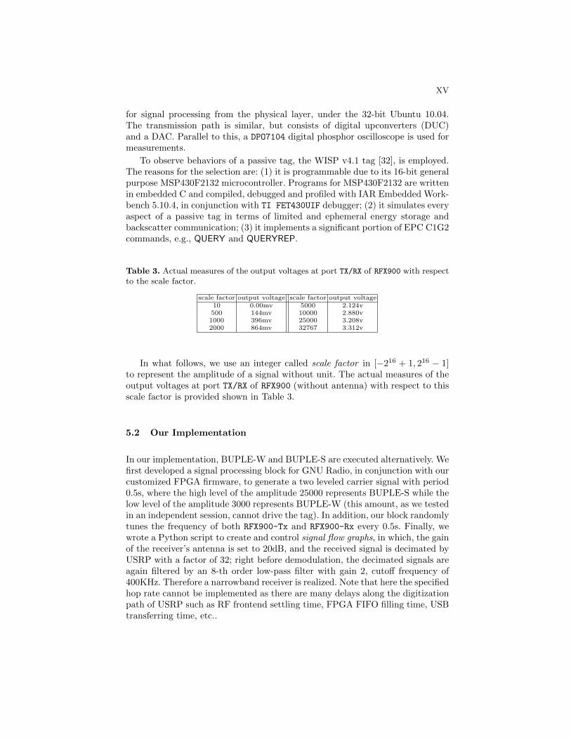
for signal processing from the physical layer, under the 32-bit Ubuntu 10.04.The transmission path is similar, but consists of digital upconverters (DUC)and a DAC. Parallel to this, a DPO7104 digital phosphor oscilloscope is used formeasurements.
To observe behaviors of a passive tag, the WISP v4.1 tag [32], is employed.The reasons for the selection are: (1) it is programmable due to its 16-bit generalpurpose MSP430F2132 microcontroller. Programs for MSP430F2132 are writtenin embedded C and compiled, debugged and profiled with IAR Embedded Work-bench 5.10.4, in conjunction with TI FET430UIF debugger; (2) it simulates everyaspect of a passive tag in terms of limited and ephemeral energy storage andbackscatter communication; (3) it implements a significant portion of EPC C1G2commands, e.g., QUERY and QUERYREP.
Table 3. Actual measures of the output voltages at port TX/RX of RFX900 with respectto the scale factor.
scale factor output voltage scale factor output voltage10 0.00mv 5000 2.124v500 144mv 10000 2.880v1000 396mv 25000 3.208v2000 864mv 32767 3.312v
In what follows, we use an integer called scale factor in [−216 + 1, 216 − 1]to represent the amplitude of a signal without unit. The actual measures of theoutput voltages at port TX/RX of RFX900 (without antenna) with respect to thisscale factor is provided shown in Table 3.
5.2 Our Implementation
In our implementation, BUPLE-W and BUPLE-S are executed alternatively. Wefirst developed a signal processing block for GNU Radio, in conjunction with ourcustomized FPGA firmware, to generate a two leveled carrier signal with period0.5s, where the high level of the amplitude 25000 represents BUPLE-S while thelow level of the amplitude 3000 represents BUPLE-W (this amount, as we testedin an independent session, cannot drive the tag). In addition, our block randomlytunes the frequency of both RFX900-Tx and RFX900-Rx every 0.5s. Finally, wewrote a Python script to create and control signal flow graphs, in which, the gainof the receiver’s antenna is set to 20dB, and the received signal is decimated byUSRP with a factor of 32; right before demodulation, the decimated signals areagain filtered by an 8-th order low-pass filter with gain 2, cutoff frequency of400KHz. Therefore a narrowband receiver is realized. Note that here the specifiedhop rate cannot be implemented as there are many delays along the digitizationpath of USRP such as RF frontend settling time, FPGA FIFO filling time, USBtransferring time, etc..

XVI
Fig. 6. Devices employed in our implementation and testing: one DPO7104 oscilloscope,one USRP (v1.0), two RFX900 daughterboards, one VERT900 antenna, one circular po-larity panel antenna, one WISP tag (v4.1) and one TI FET430UIF debugger.
BUPLE-W
BUPLE-S
tag is powerless
tag is charging
amplitude of tag's response
amplitude of carrier
Fig. 7. Time domain measurements when BUPLE works with a WISP tag.
For the tag side, we slightly modified the firmware of the WISP tag to let itintermittently answers “1010101010101010”5 at vT = 250KHz followed each timeby a sleep, when it has enough power, rather than implementing the command-based reader-tag interaction. This is because our physical layer scheme is essen-tially independent from upper layer protocols. Figure 7 exhibits how our schemeworks in a standard office setting with the tag placed in between the transceiverand receiver – it is 9.8cm away from RFX900-Tx’s antenna and 131cm away fromRFX900-Rx’s antenna. As we can see, the backscatter communication carries outnormally in BUPLE-S while it can only last for a while in BUPLE-W before thetag uses up its power. As long as the execution time of BUPLE-W is reduced,it is possible to keep the tag always alive.
Eavesdropping BUPLE Enhanced Communication: To further inves-tigate the eavesdropper’s performance while BUPLE is running, we conduct-ed the following tests in the same physical environment: centering RFX900-Tx
at 915MHz while centering RFX900-Rx at frequencies ranging from 915MHz to918MHz, we measured the amplitudes of the backscattered signals on BUPLE-S
5 This actually transmits a “1”: the tag encodes “1” as “11111111” with the (8, 1)-WCC, and each “1” in “11111111” is mapped to “10” as specified by BUPLE.

XVII
and BUPLE-W respectively, which are expected to exhibit the loss of commu-nication reliability if the eavesdropper works at a wrong frequency.
We tabulated the results in Table 4. In both BUPLE-S and BUPLE-W, thecarrier’s amplitudes as well as those of the tag’s responses drop quickly if theeavesdropper’s receiver is not centered at the right frequency. By “N/A”, wemean the signal is submerged in noise and cannot be observed. The experimen-tal evidences support the theoretic hypothesis that to detect the presence offrequency hopped signals in BUPLE-W is non-trivial, let alone demodulate anddecode them. We conducted this experiment for reader/tag/eavesdropper withvarying distances/angles and get the similar results.
Table 4. Amplitudes of signals captured by the eavesdropper working at 915MHz to918MHz.
Rx’s Freq. BUPLE-S BUPLE-Wamp. of carrier amp. of tag’s response amp. of carrier amp. of tag’s response
915MHz 24700 564 2980 91916MHz 6000 389 600 N/A917MHz 4300 210 270 N/A918MHz 300 N/A 200 N/A
Implementing On-tag WCC Encoders: To evaluate the cost of WCCencoders, we implemented them on the MSP430F2132 of a WISP tag (with-out WISP’s firmware since the firmware itself consumes a considerable portionof SRAM [27]) and tested memory consumption and throughput. We employa 23-stage LFSR with each stage in F8
2 as the random source for each WCC.To be mentioned, the encoding processes of (8, 1)-WCC and (8, 4)-WCC areimplemented using pre-computed lookup tables while that of (16, 8)-WCCs iscomputed on-the-fly by the underlying Boolean calculations. This is becausewhen n = 16, the desired lookup table (of size 128KB) is far greater than thememory provided. To generate the code with maximal speed, we set the opti-mization level to be “high-speed” for the compiler. We then record the cyclecounts through the FET debugger by letting the encoders execute at 8MHz onMSP430F2132 for 1000 times with random messages as inputs.
Table 5. Performance comparison of the proposed WCC encoders and four lightweightciphers from literature. Note that PRESENT is implemented on a different-but-similarmicrocontroller platform – Atmel AVR ATmega163.
SRAM [byte] Flash [byte] Initialization [cycle] Throughput [bits/sec](8, 1)-WCC 690 0 0 740,936(8, 4)-WCC 732 0 0 621,346(16, 8)-WCC 1,348 0 0 86,776
Hummingbird[8] 1, 064 0 9, 667 53, 024AES[17] 13,448 92 1,745 199,377KASUMI[17] 9,541 64 1,381 90,395
PRESENT[22] 2, 398 528 − 53, 361

XVIII
Table 5 summarizes the performance of WCC encoders, together with thatof four lightweight ciphers implemented on the same or similar microcontrollerplatforms. Thanks to the simple operations, WCCs consume less resource andhave higher throughput. The (16, 8)-WCC encoder is resource-hungry becausethe pure embedded C code, as we used, is inefficient to process Boolean func-tions such as Eq. (4). Appropriate mixing of inline assembly code will allow theconsumed resource be further decreased; this is part of our future work. Anothernoteworthy merit is that WCCs are more survivable in a frequent-loss-of-powerenvironment since (1) they have the zero initialization time; and (2) they have avery small computation granularity, e.g., the only operation needed is a simplemapping from {0, 1}m to {0, 1}n. On the contrary, an on-tag cipher, composingof many operations in series, is more likely to be interrupted. In all, togetherwith Table 2, we found that (8, 4)-WCC makes the information rate, the secu-rity and the implementation cost well-balanced, which is a favorable choice forpractitioners.
6 Conclusion
Given the likely importance of RFID technology in practice, security and priva-cy problems should be solved before worldwide deployment. In this paper, wepropose to enhance the physical layer of the passive RFID communication. Thesecurity and usability are further confirmed by our implementations and testingresults. Through the BUPLE scheme and proposed WCCs, a confidentiality-,authenticity- and integrity-preserving channel is created for tag-to-reader com-munication. It is also worth emphasizing that our solutions are designed for,but not limited to passive RFID systems, e.g, it is applicable to the backscatterwireless sensor network, e.g., [31], for establishing secret communication.
References
1. G. Avoine, C. Floerkemeier and B. Martin, RFID distance bounding multistate en-hancement, Progress in Cryptology, INDOCRYPT’09, LNCS 5922, Springer-Verlag,pp. 290-307, 2009.
2. A. Bogdanov, L. Knudsen, G. Leander, C. Paar, A. Poschmann, M. Robshaw, Y.Seurin and C. Vikkelsoe, PRESENT: an ultra-lightweight block cipher, CryptographicHardware and Embedded Systems, CHES’07, pp. 450-466, 2007.
3. C. Carlet, Vectorial Boolean Functions For Cryptography, Cambridge UniversityPress, 2010.
4. Circular Polarity Pane Antenna, http://www.arcadianinc.com/datasheets/4123.pdf.5. C. Castelluccia and G. Avoine, Noisy tags: a pretty good key exchange protocol for
RFID tags, International Conference on Smart Card Research and Advanced Appli-cations, LNCS 3928, Springer-Verlag, pp. 289-299, 2006.
6. I. Csiszar, J. Korner, Broadcast channels with confidential messages, IEEE Trans-actions on Information Theory, vol. 24, no. 3, pp. 339-348, 2002.
7. M. Cagalj, S. Capkun, R. Rengaswamy, I. Tsigkogiannis, M. Srivastava and J.P.Hubaux, Integrity (I) codes: message integrity protection and authentication over

XIX
insecure channels, 29th IEEE Symposium on Security and Privacy, S&P’08, pp. 279-294, 2006.
8. D. Engels, X. Fan, G. Gong, H. Hu and E. M. Smith, Hummingbird: ultra-lightweight cryptography for resource-constrained devices, 14th International Con-ference on Financial Cryptography and Data Security, FC’10, pp. 3-18, 2010.
9. EPC Global, Class 1 Generation 2 UHF air interface protocol standard v1.2,http://www.epcglobalinc.org, 2008.
10. Ettus Research LLC, The USRP and RFX900 daughter boards,http://www.ettus.com/products.
11. L. Francis, G. Hancke, K. Mayes and K. Markantonakis, Practical NFC peer-to-peer relay attack using mobile phones, Workshop on RFID Security, RFIDSec’10,LNCS 6370, Springer-Verlag, pp. 35-49, 2010.
12. GNU Radio, http://www.gnu.org/software/gnuradio.13. G. Hancke and M. Kuhn, An RFID distance bounding protocol, Conference onSecurity and Privacy for Emerging Areas in Communication Networks, SecureCom-m’06, 2005.
14. H. Gilbert, M.J.B. Robshaw and Y. Seurin, HB#: increasing the security andefficiency of HB+, Advances in Cryptology, EUROCRYPT’08, pp. 361–378, 2008.
15. D.M. Dobkin, The RF in RFID: passive UHF RFID in practice, Newnes, 2007.16. A. Juels, R. L. Rivest and M. Szydlo, The blocker tag: selective blocking of RFID
tags for consumer privacy, 10th ACM Conference on Computer and CommunicationsSecurity, CCS’03, pp. 103-111, 2003.
17. Y. W. Law, J. Doumen and P. Hartel, Survey and benchmark of block ciphers forwireless sensor networks, ACM Transactions on Sensor Networks, vol. 2, no. 1, pp.65-93, 2006.
18. J. Munilla and A. Peinado, Distance bounding protocols for RFID enhanced byusing void-challenges and analysis in noisy channels, Wireless Communications andMobile Computing, vol. 8, no. 9, pp. 1227-1232, 2008.
19. K. Ouafi, R. Overbeck and S. Vaudenay, On the security of HB# against a Man-in-the-Middle attack, Advances in Cryptology, ASIACRYPT’08, pp. 108-124, 2008.
20. L.H. Ozarow and A.D. Wyner, Wire-tap channel II, Advances in Cryptology, EU-ROCRYPT’84, pp. 33-50, 1985.
21. M.B. Pursley, Introduction to Digital Communications, Pearson Prentice Hall,2005.
22. A. Poschmann, Lightweight cryptography - cryptographic engineering for a perva-sive world, Ph.D. Thesis, Ruhr-Universitaet Bochum, Germany, 2009.
23. M. Strasser, S. Capkun, C. Popper and M. Cagalj, Jamming-resistant key estab-lishment using uncoordinated frequency hopping, 29th IEEE Symposium on Securityand Privacy, S&P’08, pp. 64-78, 2008.
24. D.R. Stinson and J.L. Massey, An infinite class of counterexamples to a conjectureconcerning nonlinear resilient functions, Journal of Cryptology, vol. 8, no. 3, pp. 167-173, 1995.
25. O. Savry, F. Pebay-Peyroula, F. Dehmas, G. Robert and J. Reverdy, RFID noisyreader: how to prevent from eavesdropping on the communication?, 9th InternationalWorkshop on Cryptographic Hardware and Embedded Systems, CHES’07, vol. 4727,pp. 334-345, 2007.
26. M.K. Simon, J. K. Omura, R.A. Scholtz and B.K. Levitt, Spread Spectrum Com-munications Handbook, McGraw-Hill Professional Publishing, 2001.
27. N. Saxena and J. Voris, We can remember it for you wholesale: implications ofdata remanence on the use of RAM for true random number generation on RFIDtags, Workshop on RFID Security, RFIDSec’09, 2009.

XX
28. A. Thangaraj, S. Dihidar, A.R. Calderbank, S.W. McLaughlin and J.M. Merolla,Applications of LDPC codes to the wiretap channel, IEEE Transactions on Infor-mation Theory, vol. 53, no. 8, pp. 2933-2945, 2007.
29. R. Trujillo-Rasua, B. Martin and G. Avoine, The poulidor distance-bounding pro-tocol, Workshop on RFID Security, RFIDSec’10, LNCS 6370, Springer-Verlag, pp.239-257, 2010.
30. VERT900 Antenna, http://www.ettus.com/downloads/VERT900.pdf.31. G. Vannucci, A. Bletsas and D. Leigh, A software-defined radio system for backscat-
ter sensor networks, IEEE Transactions on Wireless Communications, vol. 7, no. 6,pp. 2170–2179, 2008.
32. Wireless Identification and Sensing Platform (WISP), http://wisp.wikispaces.com.33. A.D. Wyner, The wire-tap channel, Bell Systems Technical Journal, vol. 54, pp.
1355-1387, 1975.34. S. Weis, S. Sarma, R. Rivest and D. Engels, Security and privacy aspects of low-
cost radio frequency identification systems, Security in Pervasive Computing, pp.50-59, 2004.
35. S. Haykin, Cognitive radio: brain-empowered wireless communications, IEEE Jour-nal on Selected Areas in Communications, vol. 23, no. 2, pp. 201-220, 2005.
A Wyner’s Coset Coding
Let C be an [n, n−m] binary linear code with the parity check matrix H. We canpartition the n-bit vector space Fn2 into 2n−m subsets in the following fashion.For any fixed vector a ∈ Fn2 , the set,
Ci = a⊕ C = {a⊕ c|c ∈ C},
is called a coset of C. Two cosets are either disjoint or coincide (partial overlapis impossible). The minimum weight vector in a coset is called the coset leader.It may have more than one coset leaders, then just randomly chooses one. Inaddition, let g1(.) : {0, 1}m 7→ i, 0 ≤ i ≤ 2m − 1, g2(.) : {0, 1}m 7→ {0, 1}m betwo public injective functions.
To transmit anm-bit secret message s, the sender propagates over the channelan n-bit vector x, which is selected randomly among all vectors in Cg1(s). Let abe the coset leader of Cg1(s). The intended receiver decodes by computing:
HxT = H(cT ⊕ aT ) = HaT , s = g2(HaT ),
where the second last identity comes from HcT = 0, which is the property ofthe linear code C. On the other hand, after receiving z = x + e where e ∈ Fn2is a binary error vector introduced by the noisy channel, the eavesdropper doesthe following:
H(x⊕ e)T = H(cT ⊕ aT ⊕ eT ) = H(aT ⊕ eT ), s′ = g2(H(aT ⊕ eT )),
which implies that the transmitted message is masked by a true random sequencee. In our implementations, g2(.) is saved by arranging the syndrome in a properorder.