
Bulletin of the Technical Committee on - Welcome to...
58
Bulletin of the Technical Committee on March 1999 Vol. 22 No. 1 IEEE Computer Society Letters Letter from the Editor-in-Chief ...................................................... David Lomet 1 Letter from the Special Issue Editor ............................................ Elke A. Rundensteiner 2 Special Issue on Data Transformations Tools for Data Translation and Integration......................................................... ............. Serge Abiteboul, Sophie Cluet, Tova Milo, Pini Mogilevsky, Jerome Sim´ eon and Sagit Zohar. 3 Meta-Data Support for Data Transformations Using Microsoft Repository ................................ ................................................. Philip A. Bernstein and Thomas Bergstraesser. 9 Metadata Transformation and Management with Oracle interMedia..................................... ....................................... Marco Carrer, Ashok Joshi, Paul Lin, and Alok Srivastava. 15 Flexible Database Transformations: The SERF Approach......... Kajal T. Claypool and Elke A. Rundensteiner. 19 Specifying Database Transformations in WOL................... Susan B. Davidson and Anthony S. Kosky. 25 Transforming Heterogeneous Data with Database Middleware: Beyond Integration......................... Laura Haas, Renee Miller, Bartholomew Niswonger, Mary Tork Roth, Peter Schwarz, and Edward Wimmers. 31 Repository Support for Metadata-based Legacy Migration. . . Sandra Heiler, Wang-Chien Lee, and Gail Mitchell. 37 Independent, Open Enterprise Data Integration. . . Joseph M. Hellerstein, Michael Stonebraker, and Rick Caccia. 43 Supporting Retrievals and Updates in an Object/Relational Mapping System................. Jack Orenstein. 50 Conference and Journal Notices ICDE’2000 Data Engineering Conference ....................................................
Transcript of Bulletin of the Technical Committee on - Welcome to...

Bulletin of the Technical Committee on
DataEngineeringMarch 1999 Vol. 22 No. 1 IEEE Computer Society
LettersLetter from the Editor-in-Chief . . . . . . . . . . . . . . . . . . . . . . . . . . . . . . . . . . . . . . . . . . . . . . . . . . . . . .David Lomet 1Letter from the Special Issue Editor . . . . . . . . . . . . . . . . . . . . . . . . . . . . . . . . . . . . . . . . . . . .Elke A. Rundensteiner 2
Special Issue on Data Transformations
Tools for Data Translation and Integration. . . . . . . . . . . . . . . . . . . . . . . . . . . . . . . . . . . . . . . . . . . . . . . . . . . . . . . . .. . . . . . . . . . . . .Serge Abiteboul, Sophie Cluet, Tova Milo, Pini Mogilevsky, Jerome Sim´eon and Sagit Zohar. 3
Meta-Data Support for Data Transformations Using Microsoft Repository. . .. . . . . . . . . . . . . . . . . . . . . . . . . . . . .. . . . . . . . . . . . . . . . . . . . . . . . . . . . . . . . . . . . . . . . . . . . . . . . .Philip A. Bernstein and Thomas Bergstraesser.9
Metadata Transformation and Management with Oracle interMedia. . . . . . . . . . . . . . . . . . . . . . . . . . . . . . . . . . . . .. . . . . . . . . . . . . . . . . . . . . . . . . . . . . . . . . . . . . . .Marco Carrer, Ashok Joshi, Paul Lin, and Alok Srivastava.15
Flexible Database Transformations: The SERF Approach. . . . . . . . .Kajal T. Claypool and Elke A. Rundensteiner.19Specifying Database Transformations in WOL. . . . . . . . . . . . . . . . . . .Susan B. Davidson and Anthony S. Kosky.25Transforming Heterogeneous Data with Database Middleware: Beyond Integration. . . . . . . . . . . . . . . . . . . . . . . . .
Laura Haas, Renee Miller, Bartholomew Niswonger, Mary Tork Roth, Peter Schwarz, and Edward Wimmers.31Repository Support for Metadata-based Legacy Migration. . .Sandra Heiler, Wang-Chien Lee, and Gail Mitchell.37Independent, Open Enterprise Data Integration. . .Joseph M. Hellerstein, Michael Stonebraker, and Rick Caccia.43Supporting Retrievals and Updates in an Object/Relational Mapping System.. . . . . . . . . . . . . . . .Jack Orenstein. 50
Conference and Journal NoticesICDE’2000 Data Engineering Conference. . . . . . . . . . . . . . . . . . . . . . . . . . . . . . . . . . . . . . . . . . . . . . . . . . . .back cover

Editorial Board
Editor-in-ChiefDavid B. LometMicrosoft ResearchOne Microsoft Way, Bldg. 9Redmond WA [email protected]
Associate Editors
Amr El AbbadiDept. of Computer ScienceUniversity of California, Santa BarbaraSanta Barbara, CA 93106-5110
Surajit ChaudhuriMicrosoft ResearchOne Microsoft Way, Bldg. 9Redmond WA 98052-6399
Donald KossmannLehrstuhl fur Dialogorientierte SystemeUniversitat PassauD-94030 Passau, Germany
Elke RundensteinerComputer Science DepartmentWorcester Polytechnic Institute100 Institute RoadWorcester, MA 01609
The Bulletin of the Technical Committee on Data Engi-neering is published quarterly and is distributed to all TCmembers. Its scope includes the design, implementation,modelling, theory and application of database systems andtheir technology.
Letters, conference information, and news should besent to the Editor-in-Chief. Papers for each issue are so-licited by and should be sent to the Associate Editor re-sponsible for the issue.
Opinions expressed in contributions are those of the au-thors and do not necessarily reflect the positions of the TCon Data Engineering, the IEEE Computer Society, or theauthors’ organizations.
Membership in the TC on Data Engineering (http:www. is open to all current members of the IEEE Com-puter Society who are interested in database systems.
The web page for the Data Engineering Bulletinis http://www.research.microsoft.com/research/db/debull.The web page for the TC on Data Engineering ishttp://www.ccs.neu.edu/groups/IEEE/tcde/index.html.
TC Executive Committee
ChairBetty SalzbergCollege of Computer ScienceNortheastern UniversityBoston, MA [email protected]
Vice-ChairErich J. NeuholdDirector, GMD-IPSIDolivostrasse 15P.O. Box 10 43 266100 Darmstadt, Germany
Secretry/TreasurerPaul LarsonMicrosoft ResearchOne Microsoft Way, Bldg. 9Redmond WA 98052-6399
SIGMOD LiasonZ.Meral OzsoyogluComputer Eng. and Science Dept.Case Western Reserve UniversityCleveland, Ohio, 44106-7071
Geographic Co-ordinators
Masaru Kitsuregawa (Asia)Institute of Industrial ScienceThe University of Tokyo7-22-1 Roppongi Minato-kuTokyo 106, Japan
Ron Sacks-Davis (Australia )CITRI723 Swanston StreetCarlton, Victoria, Australia 3053
Svein-Olaf Hvasshovd (Europe)ClustRaWestermannsveita 2, N-7011Trondheim, NORWAY
DistributionIEEE Computer Society1730 Massachusetts AvenueWashington, D.C. 20036-1992(202) [email protected]

Letter from the Editor-in-Chief
Our First Electronic “Mostly” Issue
Many TC’s of the IEEE have electronic-only distribution of their news letters. We have never thought of the Bul-letin as a news letter. Indeed, there is no news section within the pages of the Bulletin except for the occasionalnews provided in my letters. Rather, the Bulletin, while an informal publication, is primarily a vehicle for dis-seminating technical information about both research and industrial practice. Most of us are still accustomed tohardcopy distribution of such publications. However, the world is changing, and, with an extra push because ofour very limited finances, we with this issue make the leap into the world of electronic media. You will no longerreceive hardcopy of the Bulletin via ordinary mail. After providing several alerts on the subject, we now expectthat members of the TCDE will access the Bulletin through our web site at
http://www.research.microsoft.com/research/db/debull.Because many of you may have waited for the hardcopy issue, rather than accessing the web site, we antici-
pate increased traffic at the Bulletin web site. Please let us know when you experience difficulties. Also, pleasesend us suggestions as to how we can improve the electronic delivery process. Finally, if you are unable to ac-cess the Bulletin via our web site and want to continue receiving hardcopy, contactTracy Woods, IEEE ComputerSociety, 1730 Massachusetts Ave., Washington, DC 20036. (Email: [email protected])
Technical Committee Meeting at ICDE’99 in Sydney, Australia
From the TCDE Web Page:All members of the TCDE are invited to the Open Meeting of the TCDE to be heldat the ICDE meeting in Sydney Australia from 17:40 to 18:30 on Wednesday March 24, 1999. ICDE Conferencedetails (hotel, registration information, program) can be found at http://www.cse.unsw.edu.au/icde99. The pur-pose of an open meeting is to inform the TC members what its executive committee has been doing and to givethe members a chance to ask questions and provide suggestions. This meeting will be chaired by Prof. Dr. ErichNeuhold, the vice-chair of the TCDE (”E.N.”).
The meeting agenda and more complete information can be found on the TCDE web site athttp://www.ccs.neu.edu/groups/IEEE/tcde/.
This Issue
Data transformations have a long history in the database field, and in our reseach literature as well. Early in theevolution of relational databases, this area attracted a substantial amount of research interest. There was then aquiescent period in which researchers largely ignored the field. More recently, however, the emergence of datawarehouses has sparked renewed interest. Data transformations, including not only model transformations andother syntactic issues, but also data scrubbing and various forms of semantic transformations became crucial forthe successful data warehouse. An added incentive for work in this area came from the web explosion, whichled to renewed interest in enterprise and cross-enterprise data integration. Data transformation is critical to mostwide-scale integration. Elke Rundensteiner has successfully solicited papers from both researchers and commer-cial organizations that provide broad coverage of the data transformation field, covering future research possibil-ities and current or soon to be available practice. Thus the issue is a very nice blend of papers that should serve asa good introduction for members of our technical community. I want to thank Elke for her hard work in bringingthis issue to fruition, and for being responsive to unanticipated scheduling constraints.
David LometMicrosoft Research
1

Letter from the Special Issue Editor
Data transformation is the bread and butter technology involved in most aspects of information management.Transformations are needed to migrate legacy systems to more modern applications, to optimize queries, to trans-late from one data model to another, to integrate heterogeneous systems into federated databases or warehouses,to perform data cleansing or scrubbing, to evolve a schema and its associated database as driven by changinguser requirements, to construct user-customized web sites, and to achieve enterprise-wide integration. While thespecific data models being transformed have grown over time to include network model, relational data model,object-oriented schema, and now possibly XML web models, the problems of how to specify such mappings,what language to employ, and how to efficiently execute them have persisted. As demonstrated by the large num-ber of authors that contributed to this issue, interest in this technology is as strong as ever. Although there area variety of products on the market that achieve some forms of transformations, many are limited to a specificproblem and/or a specific data model. How to provide a general umbrella approach solving all or at least a largeclass of the above problems remains unanswered. This issue reports upon recent efforts from academia and in-dustry both on addressing specific transformation problems as well as on developing more generic transformationapproaches.
Abiteboul, Cluet, et al. address data translation for heterogeneous sources. Their solution assumes a middle-ware data model to which data sources are mapped, along with a declarative language for specifying translationswithin this common middlelayer data model. Automation of some of the tasks of translation are studied.
Bernstein and Bergstraesser report on facilities integrated with Microsoft SQL Server 7.0 for transformingboth data and meta-data. They describe the repository functions of the meta-data manager called Microsoft Repos-itory, such as the Data Transformation Service which helps users develop programs to populate a data warehouse.
Carrer, Joshi, et al. describe the Oracle MediaAnnotator, a metadata translation and management tool to beused with Oracle8i interMedia. MediaAnnotator automatically extracts and transforms metadata from multime-dia objects into logical annotations, thus simplifying the indexing and searching of multimedia objects.
Claypool and Rundensteiner present a generic framework for flexible database transformations, called SERF.SERF can be added as thin transformation support layer on top of current schema evolution systems, enhancingthem with flexibility, extensibility and re-usability of transformations.
Davidson and Kosky introduce a declarative (Horn-clause) language, WOL, developed for specifying trans-formations involving complex types and recursive data-structures. WOL transformations, which map from asource to a target schema, are easily modified to respond to schema evolution of the source schema. WOL map-pings can explicitly resolve incompatibilities between source and target.
Haas, Miller, et al. advocate database middleware systems as transformation engines. They argue that a mid-dleware transformer must provide database-like features, in particular, transformation support for heterogeneousdata and efficient query processing capabilities to compensate for less-capable sources.
Heiler, Lee, and Mitchell apply software repository technology to the problem of legacy system migration.Correctly transforming systems (including data, programs and processes) requires metadata about the two objectsand their interrelationships. Hence, metadata repositories that provide tools for capturing, transforming, storing,and manipulating metadata are advocated for supporting the migration process.
Hellerstein, Stonebraker, and Caccia introduce the Cohera Federated DBMS as a way to add data indepen-dence back into the process of integrating heterogeneous databases. They advocate physical independence forscalable physical design of enterprise-wide data, and logical independence via the use of SQL99 to achieve anopen conversion framework.
Finally, Orenstein describes the object/relational mapping system called Enterprise Business Objects (EBO)which is part of a Java application server. Transformations used by EBO to provide transparent, high-performancedatabase access to middle-tier Java applications are characterized.
Elke A. RundensteinerWorcester Polytechnic Insitute
2

Tools for Data Translation and Integration �
Serge Abitebouly Sophie Cluety Tova Miloz Pini Mogilevskyz Jerome Simeony
Sagit Zoharz
Abstract
A broad spectrum of data is available on the Web in distinct heterogeneous sources, stored under dif-ferent formats. As the number of systems that utilize this data grows, the importance of data conversionmechanisms increases greatly. We present here an overview of a French-Israeli research project aimed atdeveloping tools to simplify the intricate task of data translation. The solution is based on amiddlewaredata modelto which various data sources are mapped, and adeclarative languagefor specifying trans-lations within the middleware model. A complementary schema-based mechanism is used to automatesome of the translation. Some particular aspects of the solution are detailed in [3, 7, 10].
1 Introduction
Data integration and translation is a problem facing many organizations that wish to utilize Web data. A broadspectrum of data is available on the Web in distinct heterogeneous sources, stored under different formats: aspecific database vendor format, XML or Latex (documents), DX formats (scientific data), Step (CAD/CAMdata), etc. Their integration is a very active field of research and development, (see for instance, for a very smallsample, [4, 5, 9, 6]). A key observation is that, often, the application programs used by organizations can onlyhandle data of a specific format. (e.g. Web browsers, like Netscape, expect files in HTML format, and relationaldatabases expect relations). To enable a specific tool to manipulate data coming from various sources (e.g. use,in a relational system, data stored on the Web in HTML format), a translation phase must take place – the data(in the source format) needs to be mapped to the format expected by the application.
The naive way to translate data from one format to another is writing a specific program for each translationtask. Examples are the Latex to HTML and HTML to text translators [8, 1]. Writing such a program is typicallya non trivial task, often complicated by numerous technical aspects of the specific data sources that are not reallyrelevant to the translation process (e.g. HTML/XML parsing, or specific DB access protocol). A sound solutionfor a data integration task requires a clean abstraction of the different formats in which data are stored, and meansfor specifying the correspondences between data in different worlds and for translating data from one world toanother. For that, we introduced amiddlewaredata model that serves as a basis for the integration task, anddeclarative rule languagesfor specifying the integration. Translation from source to target formats is achievedby (1) importing data from the sources to the middleware model, (2) translating it to another middleware repre-sentation that better fits the target structure, and then (3) exporting the translated data to the target system.
Copyright 1999 IEEE. Personal use of this material is permitted. However, permission to reprint/republish this material for ad-vertising or promotional purposes or for creating new collective works for resale or redistribution to servers or lists, or to reuse anycopyrighted component of this work in other works must be obtained from the IEEE.Bulletin of the IEEE Computer Society Technical Committee on Data Engineering
�Work partially supported by AFIRST and the Israeli Ministry of Science.yI.N.R.I.A, Rocquencourt, France Email:<firstname>.<lastname>@inria.frzTel Aviv University, Israel, Email:fmilo,pinim,[email protected]
3

A first attempt: Our first attempt (to be refined later on) was to propose a very simple middleware model wheredata is represented by ordered labeled trees. The model is very similar to the common OEM model for semistruc-tured data. A particularity here is that we allow an order to be defined on the children of nodes. Order is aninherent component of some data structures, e.g. ordered tuples and lists. Similarly, textual data can either bedescribed as a sequence of characters or words, or on a higher level by a certain parse tree; in both cases, the orderof data element is important. Supporting order as part of the data model enables a natural representation of datacoming from such sources [3]. Together with the data model, we introduced a declarative rule-based language fordescribing correspondences between data in different worlds [3]. The language has several useful properties: itprovides constructs to search and build complex trees that represent data; the semantics of rules take into consid-eration the fact that nodes may represent collections with specific properties (e.g., sets are insensitive to order andduplicates); the complexity of correspondence computation was proved to be PTIME in many practical cases. Ofcourse, deriving correspondences within existing data is only one issue in a heterogeneous context. One wouldalso want to translate data from one representation to another. Interestingly, we showed that in many practicalcases, translation rules can automatically be derived from the correspondence rules. Thus, a complete integrationtask (derivation of correspondences, transformation of data from one world to the other, incremental integrationof a new bulk of data, etc.) can be specified using asingleset of declarative rules. This was an important result.It simplifies the specification task and helps in preventing inconsistencies in specifications.
To experiment with the above translation scheme we built a prototype system, W3TRANS [11], and usedit to define mapping and translations among various formats including SGML, HTML, relational and OODBs.We soon realized that although this simplified greatly the translation specification, still, very often, a considerableprogramming effort was required when a new translation was to be defined. Our goal was thus to design additionalmechanisms to further simplify the translation. The solution was based on two main observations.
(i) Instantiation: In many cases, the translations needed by the user are combinations or specialization of othertranslations. For example consider the following application. A research institute wants to build an intranet ap-plication. Among other things, the institute stores informations about its researchers in an OODB, and keepstheir research papers in XML documents. Assume we want to provide an HTML interface to the system so thatemployees can view it on the Web. If the system happens to contain two generic programs providing an HTMLview of OO and XML data resp., then the specific application can be obtained by customizing and combining theabove programs. Following this idea we enhanced our model by a novelinstantiationmechanism, extending boththe data model and the rule-based translation language and providing a powerful mechanism for customizationand synthesis of programs. Interestingly, both the model and the rules have a natural graphical representationwhich further simplifies the programming by allowing a convenient graphical interface via which the user can,with minimal programming, customize and combine existing programs.(ii) Schema-based translation:Frequently, much of the structure of the source data is similar to that of the targettranslated data, and many of the structure modifications to be performed by the translation process are ratherstandard and result from various differences between the schemas of the source and target systems. We use herethe general termschemato denote whatever way a data model chooses to model its data. For example, databasesuse schemas to model database instances; Structured documents often obey some grammar (e.g. Document TypeDefinition – DTD – in SGML and XML); In other models such a definition may be partial (e.g. in semistructureddata [2]). The observation is that, in many translations, the schema of the target system is closely related to that ofthe source system – both schemas aim to represent the same data. This implies that a large part of the translationcan be doneautomatically, relying on this (often standard) relationship, hence reducing the programming effort,and involving the user only in the specification of the “non standard” parts of the translation.
Based on the above observations we have developed two complementary prototype systems, YAT and Tran-Scm. YAT focuses on the rule language and implements the instantiation and customization mechanisms. Tran-Scm focuses on schema analysis and automatic generation of translations when possible. Both support a conve-nient graphical interface and together provide a sound solution to the data translation problem. In the rest of this
4

Yat:
Yat
&Yat
The YAT model
*
AnyAny
Presearcher:
name
set
researcher
position interests
class
*
The Researcher model
String String
String
The Milo model
Pr1:
"Tova Milo"
name
set
researcher
position interests
class
"logic"
"Prof. Tel Aviv University"
"DB"
The XML publication model
Pentry :
title
entry
year authors
String Int*
*
Symbol
String
Pfield
Pfield: Symbol
*Pfield
author
String
A subset of the HTML model
html
head body
title
String
HtmlPage:
HtmlElement*
ul
li
String
HtmlElement
a
href
*
*
HtmlElement:
&HtmlPage
h1
String content
String
Figure 1: Some YAT Models
paper we briefly describe the main ideas underlying the two systems. For lack of space the presentation is ratherinformal and is mainly based on examples and intuitive explanations. For full details see [7, 10].
2 YAT
We explain below the main ideas using a running example - the research institute repository mentioned above.
The data model: The YAT data model consists of named ordered labeled trees that may be unioned (with the_symbol) to form a pattern. A set of patterns form a model, which is used to represent real-world data (OODB,XML and HTML in our example). The most interesting feature of YAT is that it allows to represent data at variouslevels of detail. For instance, Figure 1 shows several such models. The three models on the upper part of the figuremay be used to represent an OODB object corresponding to the researcher whose name is Tova Milo. Goingfrom left to right, the models get more and more precise. The first one allows to represent any YAT compliantdata. TheResearchermodel represents an OODB classresearcherbut also all objects belonging to that class.The last model is an actual representation of the object itself like in usual semistructured data models. Each ofthese three models is an instance of its predecessor(s). Another interesting example is the XML model in thelower left hand side of the figure. It mixes precise with non-specific informations. An XML entry is described asbeing a sequence of fields. The first fields are precisely described (i.e.,title, year, authors). Then, the patternjust indicates that they are followed by zero or more fields. Each field has a label of typeSymbol and may becomposed of a simple string or of a sequence of other fields. Finally, the last model (partially) represents anyHTML data (internal nodes, e.g.h1, ul, a, represent HTML tags).
Let us now see how these models are constructed and give an intuition of the instantiation mechanism. Thenodes of a YAT tree may be labeled with a (i) constant (e.g., ”Tova Milo”), (ii) symbol (e.g.,class, researcher,set), (iii) type (e.g.,Any, String, Symbol), (iv) pattern name (e.g.,Y at) or (v) reference to a pattern name(e.g.,&Y at). The edges of a YAT tree may be annotated by an occurrence symbol. In the example, there is onlyone such symbol:?. It indicates the possibility to replace the annotated edge by an arbitrary number of edges(e.g., the twoset rooted subtrees).
A model is an instance of another, if one can find a mapping between their edges and nodes. An edge isinstantiated according to its occurrence symbol. A node is instantiated according to the following rules:
5

HtmlPageAll() :htmlh ! head! title! ”Verso Researchers”;
! bodyh ! ul?
! li! a
h ! href ! &HtmlPage(N);! content! Niii
(=Presearcher :class! researcher
h ! name! N;
! position! P;
! interests! set?
! Ii
HtmlPage(N) :htmlh ! head! title! H1;
! bodyh ! h1! H1;! ”Position is ”;! P
! ul[]T! lih ! ”title : ” ;
! T;
! ”published in ”;! Y iii
(=Pentry :entryh ! title! T;
! year ! Y;
! authors?
! set! N;?
! Pfieldi,Presearcher :class! researcher
h ! name! N;
! position! P;
! interests! set?
! Ii;H1 is concat(”Homepage of ”; N)
Figure 2: RuleAll Researchers Figure 3: RuleSingle Researcher
� A constant/symbol node can be instantiated by nodes with an identical label (e.g., the nodes labeledclass).
� A type node can be instantiated by a node whose label is a subtype or an instance of that type. E.g., thenode labeledAny can be instantiated by the nodes labeledString, Symbol, ”Tova Milo” or class.
� A pattern node can be instantiated by a tree, instance of that pattern. E.g., the two trees whose roots arelabeledresearcher are instances of theY at labeled node.
� A referenced pattern node can be instantiated by a node whose label is a reference to an instance of thatpattern. E.g. the&HtmlPage labeled node is instance of the&Y at labeled node.
Defining translations: Now that we are able to describe the structural input (OODB and XML) and output(HTML) of our application, we need a way to map the former to the later. This is done using the translationlanguage YATL (either directly or through its graphical interface) that allows to describe complex conversionson graphs. It is rule-based, each rule describing a small part of the data conversion. For space reasons we willnot give the complete program allowing to map researcher objects and XML documents to HTML but two sim-plified, yet significant, rules. Although, the syntax may look somewhat complicated, note that: (i) most of thetime, the programmer only has to modify some rules already existing in the system and, from our experience,can master the syntax of the rules rather fast; (ii) the programmer has the option to use the graphical interface tomodify such rules [7]. We now illustrate the YATL language on two simplified rules of the example application.
Consider the ruleAll Researcherson Figure 2. This rule creates a single Web page that contains a list ofpointers to all researchers in the database. On the lower part of the rule (i.e., after the(= symbol), the patternPresearcher is used to filter the input data and retrieve the required information through variable bindings (inthe example, the researchers names are bound to VariableN ). On the upper part, the output pattern describes howthe HTML structure is generated. The output of the rule is identified by a Skolem function:HtmlPageAll().
6

The fact that this Skolem function has no parameter indicates that only one pattern will be generated, including thetransformation of all the input filtered data. The head of the rule contains a reference to another Skolem function,this time parameterized by the researchers names (&HtmlPage(N)). Note also that we could have used theresearcher’s identity as a parameter, replacingN byPresearcher in the Skolem function. As it is, there willbe one reference per researcher name. The HTML page associated to this reference is described by another ruleSingle Researchergiven in Figure 3.
This rule computes the page associated to one researcher identified by its name. It integrates data from theOODB and the XML files. Its input is a set of patterns, instances of thePentry and thePresearcher pat-terns. Its output is a new HTML page identified by theHtmlPage(N) Skolem function. Remark that VariableN is used in bothPentry andPresearcher patterns, making the correspondence between a given researcherin the object database and its publications in the XML file. The page titleH1 is generated using a function thatconcatenates two string. Among other things, the page contains a list of the researcher publications (ul), which
is ordered by title. This is specified by the[]T! edge which states that a new child is created for each distinct title
T (grouping) and that the children must be ordered according to the value ofT (ordering). The ordering possi-bilities of YATL are mandatory to manage Web documents, and can be used for example to give several viewsof a given list of publications (ordered by title, by publication date, by authors, etc).
Just like the data model, translation rules can also be instantiated and customized for specific needs. Theprogrammer can start with a general program that can be instantiated into one that corresponds to the given input.Customization can follow. For example, through successive instantiations/customizations, we can find programsgenerating HTML pages from (i) any input, (ii) an arbitrary OODB (iii) data corresponding to a specific OODBschema or (iv) an object of that schema. It is also possible to compose programs and efficiently build complextranslations out of simple, previously defined blocks. We omit this here for lack of space.
3 TranScm
To further simplify the programming, we observe that in many cases the schema of the data in the source systemis very similar to that of the target system. In such cases, much of the translation work can be done automatically,based on the schemas similarity. This can save a lot of effort for the user, limiting the amount of programmingneeded. The TranScm system implements the above idea. Given the schemas for the source and target data, thesystem examines the schemas and tries to find similarities/differences between them. This is done using a rule-based method, where each rule (1) defines a possible common matching between two schema components, and (2)provides means for translating an instance of the first to an instance of the second. The system has a set of build-in rules that handles most common cases, and that can be extended/adjusted/overridden by the user during thetranslation process. The system uses the rules and tries to find for each component of the source schema a unique“best matching” component in the target schema, or determine that the component should not be represented inthe target. This is called thematching process. If the process succeeds, the data translation can be performedautomatically using the translation facilities of the matching rules. There are two cases where the process mayfail: (i) a component of the source schema cannot be matched with a target one using the current set of rules,(and the matching process can neither derive that the component should be just ignored), or (ii) a componentof the source schema matches several components in the target schema, and the system cannot automaticallydetermine which is the “best” match. For (i) the user can add rules to the system to handle the special componentand describe the translation to be applied to it. For (ii) the user is asked to determine the best match. Then, basedon the user’s input, the matching process is completed and the translation is enabled.
Handling schemas of different sources requires a common framework in which they can be presented andcompared. Note however that the middleware model presented above, with its instantiation mechanism, allows topresent not only data but also schema, hence can serve as such common framework. (In the actual implementationof the system we used a slightly more refined model, but the differences are irrelevant for the purpose of the
7

current paper). Similarly, the match&translate rules used by the system could be defined in the style of YATL.(In fact, the system provides a generic interface for rules, independent of the specific language used to specifythem. This enabled us for example to use in the prototype Java as the rule definition language.)
A typical scenario of the system’s work is as follows. It receives as input two schemas, one of the data sourceand the other of the target. The two schemas are imported into the system and presented in the common schemamodel. The next step is matching. The system tries to find for every component in the source schema a cor-responding component in the target schema (or determine that the component should not be represented in thetarget), using the rule-based process mentioned above. Once the matching is completed (perhaps with the user’sassistance), a data translation is possible. To perform the translation, a data instance of the source schema isimported to the common data model, and is “typed”, i.e. every element in the data is attached a correspondingschema element as a type. Now, the system uses the match between the schema components, achieved in theprevious step, to translate the data. Recall, from above, that every rule in the system has two components, thefirst defines a possible common matching between two components of schemas, and the second provides meansfor translating an instance of the first to an instance of the second. Every element of the source data is translated,using the translation function of the rule that matched its type with a type (component) of the target schema, toan instance of the target type. The resulting elements are “glued” together to form a valid instance of the targetschema. Finally, the translated data is exported to the target application.
To conclude, note that the schema-based translation method is not aimed atreplacingthe YATL programminglanguage, but rather tocomplementit - rather than writing a translation program for all the data, much of thetranslation will be done automatically by the system, based on the schema matching, and the programmer needsto supply only some minimal additional code handling the data components not covered by the system.
References
[1] The html2text translator, 1996. Available by fromhttp://www.scanline.com/html2txt/ .
[2] S. Abiteboul. Querying semi-structured data. InProc. ICDT 97, pages 1–18, 1997.
[3] S. Abiteboul, S. Cluet, and T. Milo. Correspondence and translation for heterogeneous data. InProc. ICDT 97, pages351–363, 1997.
[4] P. Buneman, S. Davidson, G. Hillebrand, and D. Suciu. A query language and optimization techniques for unstructureddata. InProc. of the ACM SIGMOD Conf. on Management of Data, pages 505–516, 1996.
[5] M.J. Carey et al. Towards heterogeneous multimedia information systems : The Garlic approach. Technical ReportRJ 9911, IBM Almaden Research Center, 1994.
[6] S. Chawathe, H. Garcia-Molina, J. Hammer, K. Ireland, Y. Papakonstantinou, J. Ullman, and J. Widom. The TSIMMISproject: Integration of heterogeneous information sources. InProceedings of IPSJ Conference, pages 7–18, Tokyo,Japan, October 1994.
[7] S. Cluet, C. Delobel, J. Simeon, and K. Smaga. Your mediators need data conversion! InProc. of the ACM SIGMODConf. on Management of Data, pages 177–188, 1998.
[8] Nikos Drakos. The latex2html translator, 1996.Available fromcbl.leeds.ac.uk/nikos/tex2html/doc/latex2html.ps .
[9] A. Levy, A. Rajaraman, and J. Ordille. Querying heterogeneous information sources using source descriptions. InProc. Int. Conf. on Very Large Data Bases (VLDB), pages 251–262, 1996.
[10] T. Milo and S. Zohar. Using schema matching to simplify heterogeneous data translation. InProc. Int. Conf. on VeryLarge Data Bases (VLDB), pages 122–133, 1998.
[11] Pini Mogilevsky. W3trans translation system, 1996.Available fromwww.math.tau.ac.il/pinim/w3trans-home.html .
8
Meta-Data Support for Data Transformations Using MicrosoftRepository
Philip A. Bernstein Thomas BergstraesserMicrosoft Corporation
[philbe, thomberg]@microsoft.com
Abstract
Data warehousing requires facilities for moving and transforming data and meta-data. This paper de-scribes such facilities that are integrated with Microsoft SQL Server 7.0, particularly as they relate tometa-data and information models in its shared repository. It also discusses the use of XML to movemeta-data between tools.
1 Introduction
To interpret data, users and applications need meta-data. Therefore, whenever data is moved or transformed,meta-data needs to be involved. Meta-data controls the movement by specifying such information as location,schedule, and source-to-target mappings. It needs to be moved along with the data so that further work can bedone on the data after the move. Meta-data that describes the data movement activity is also useful to retrace datamovement steps later on.
Like any kind of data, meta-data requires a persistent data store (i.e., a repository) in which to keep it [1]. Italso requires an information model (i.e., schema) that describes the meta-data to be managed. The informationmodel supports the integration of relevant tools and enables sharing of meta-data through the repository.
Today, the most common application environment in which data is moved and transformed is the data ware-house, an increasingly important part of an enterprise’s information architecture. The amount and diversity ofmeta-data required in a data warehouse makes it a natural application of repository technology. Schema man-agement for source and target data sources, aggregation information, scheduling of tasks, and system topologyare examples of meta-data that needs to be managed.
Data warehousing scenarios are major applications of Microsoft1 Repository, a meta-data manager that shipswith Microsoft SQL Server 7.0. It includes a repository engine that sits on top of Microsoft SQL Server and sup-ports both navigational access via object-oriented interfaces and SQL access to the underlying store. MicrosoftRepository also includes the Open Information Model, a repository schema that covers the kinds of meta-datathat are needed for data warehouse scenarios. One of the many users of the repository is SQL Server’s DataTransformation Service (DTS), a tool that helps users design programs to populate a data warehouse.
Copyright 1999 IEEE. Personal use of this material is permitted. However, permission to reprint/republish this material for ad-vertising or promotional purposes or for creating new collective works for resale or redistribution to servers or lists, or to reuse anycopyrighted component of this work in other works must be obtained from the IEEE.Bulletin of the IEEE Computer Society Technical Committee on Data Engineering
1ActiveX, Microsoft and Visual Basic are trademarks of Microsoft Corporation.
9
This paper describes facilities that support the movement and transformation of data and meta-data, particu-larly as they relate to the repository functions that support them. Section 2 describes data warehouse scenarios inmore detail, and how DTS addresses them. Section 3 discusses the problem of sharing and exchanging meta-datavia XML. Section 4 summarizes some future directions.
The first release of Microsoft Repository and the Open Information Model was in early 1997 in Visual Basic5.0 [2]. The second release, which includes version and workspace management and a much expanded informa-tion model, shipped in Visual Studio 6.0 and SQL Server 7.0 in late 1998 [3]. The product also has a softwaredevelopment kit (SDK) that includes tools for designing and extending information models. Details are availableat [7].
2 Populating a Data Warehouse
The most labor-intensive parts of creating a data warehouse are cleansing and mapping. Data from many sourcesis moved through a sometimes complex scrubbing process whose goals are to normalize the representation, fil-ter out the desired information, and preserve information quality in the target system. To make this error proneprocess traceable, sophisticated systems maintain additional lineage information that links data to meta-data thatdescribes how the data was processed.
Rules must be defined and implemented to identify and resolve inconsistent data formats, missing data, in-valid data, semantic inconsistencies, and other sources of poor data quality. Often, data must be merged frommultiple data sources and reconciled. Sometimes it is aggregated into summary information. Even a relativelysimple data warehouse can require a hundred cleaning and mapping rules, with effort measured in person years.
Anecdotal evidence from consultants and users tells us that data scrubbing is over two-thirds of the work insetting up and managing a data warehouse. For this reason, there is a growing market for tools that simplify thiswork, a market that many software vendors are trying to fill. As explained earlier, these tools need meta-data:schema descriptions, libraries of transformation rules, descriptions of transformation scripts, etc.
Data warehousing is becoming one of the largest segments of the database business. SQL Server in its 7.0release addresses this segment with an easy-to-use out-of-the-box data mart solution and a platform for scalabledata warehouses. The main built-in components are an OLAP engine for accessing multi-dimensional data (Mi-crosoft Decision Support Services) and a data movement tool (Data Transformation Service (DTS)). Meta-datamanagement and extensibility come via Microsoft Repository and the Open Information Model.
DTS is a graphical tool for constructing and running transformation packages. Each package is a workflowthat defines a transformation. It consists of a set of partially ordered steps, each of which invokes a task. Such atask can execute SQL statements, call an ActiveX script or external program, perform a bulk insert, send E-mail,transfer whole database objects, or call a data pump.
Data pump tasks are the main workhorse. They retrieve and store data through OLE DB, which defines astandard interface for access to heterogeneous data [4]. Each data pump task copies and/or transforms data fromOLE DB data sources to OLE DB data targets. It consists of a set of transformations, each of which maps a setof input tables and columns to a set of output tables and columns. A transformation ranges from a simple copyoperation to the invocation of a custom C++ program or ActiveX script.
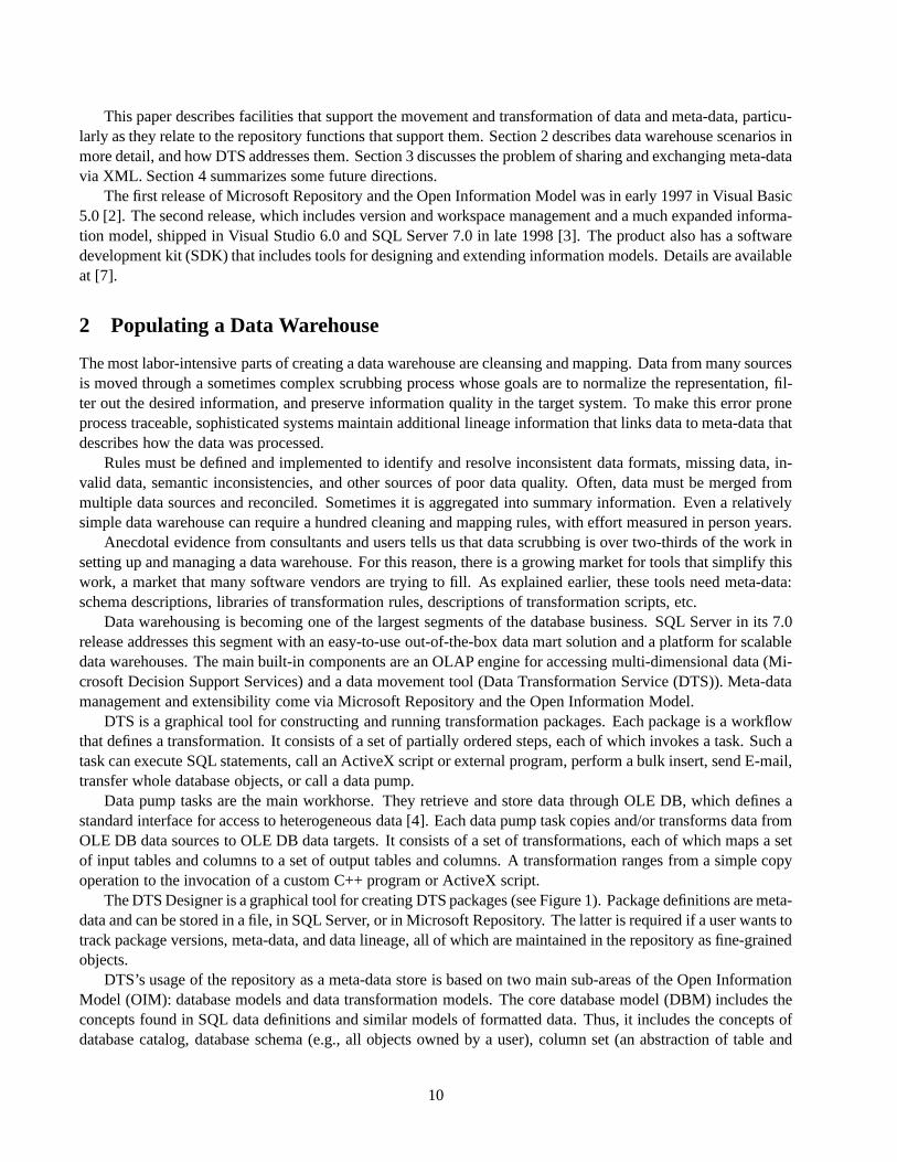
The DTS Designer is a graphical tool for creating DTS packages (see Figure 1). Package definitions are meta-data and can be stored in a file, in SQL Server, or in Microsoft Repository. The latter is required if a user wants totrack package versions, meta-data, and data lineage, all of which are maintained in the repository as fine-grainedobjects.
DTS’s usage of the repository as a meta-data store is based on two main sub-areas of the Open InformationModel (OIM): database models and data transformation models. The core database model (DBM) includes theconcepts found in SQL data definitions and similar models of formatted data. Thus, it includes the concepts ofdatabase catalog, database schema (e.g., all objects owned by a user), column set (an abstraction of table and
10

Figure 1: The DTS Designer
view), table, view, constraint, trigger, stored procedure, and column.OIM is described in the Unified Modeling Language (UML) [5, 6, 8]. It also uses UML as its core model from
which sub-models of OIM inherit. Inheriting UML concepts reduces the overall size of the model and promotessharing between sub-models. For example, a subset of DBM is shown in Figure 2, where gray boxes denote UMLcore concepts from which DBM concepts inherit: catalog and schema inherit from UML package (UML’s generalcontainer concept); column set, table, and view inherit from UML type; and column inherits from UML attribute(a structural feature of a UML type). Similarly, constraint inherits from UML constraint and trigger inherits fromUML method (not shown in the figure). Some DBM concepts do not have natural analogs in UML, such as keyand index, so they inherit from the very abstract UML concept of model element.
3DFNDJH
(OHPHQWV(OHPHQW
0RGHO(OHPHQW
7\SH 0HPEHU0HPEHUV
&DWDORJ
6FKHPD4XHU\
9LHZ
&ROXPQ6HW
7DEOH
$WWULEXWH
&ROXPQ
.H\
,QGH[ ,QGH[&ROXPQ
$VVRFLDWLRQ
$VVRFLDWLRQ5ROH
-RLQ5ROH
(OHPHQWV
3DUWLFLSDWHV
.H\V &ROXPQV
$VVRFLDWLRQ5ROHV
.H\5HIHUHQWLDO5ROH
,QGH[HV
,QGH[&ROXPQV
,QGH[&ROXP
QV
Legend inheritance relationship inherited object
Figure 2: Database Information Model (DBM)
The database information model is populated with schema information by utilities included with SQL Server.The utilities use OLE DB and therefore can import schemas from any OLD DB data source, which include mostpopular database products (see http://www.microsoft.com/data/oledb/).
The transformation model (TFM) is another sub-model of OIM, which captures information about compounddata transformation scripts (see Figure 3). An individual transformation (which is a specialization of UML method)can have relationships to the sources and targets of the transformation. Transformation semantics can be capturedby constraints and by code-decode sets for table-driven mappings. Transformations can be grouped into a task
11

(the unit of atomic execution), which is invoked by steps (the unit of scheduling) within a top-level package(which is a specialization of the generic UML package).
To support data lineage, package executions are also modeled. When a package is executed, DTS stores adescription of that package execution in the repository. It also optionally tags each data warehouse row by theidentifier of the package execution that produced it. This identifier enables traceability from the row in a data tableto the repository’s description of package execution that populated or updated it. From there, one can trace backto the package transformations, the sources and targets of the transformation, etc., to get a complete descriptionof where that row came from.
3DFNDJH
(OHPHQWV
7UDQVIRUPDWLRQ3DFNDJH
(OHPHQW
0RGHO(OHPHQW
7UDQVIRUPDWLRQ6WHS
7UDQVIRUPDWLRQ7DVN
7\SH
([HFXWHV 7UDQVIRUP6RXUFH
7UDQVIRUP7DUJHW
0HPEHU0HPEHUV
7UDQVIRUPDWLRQ
7UDQVIRUPDWLRQ&ROXPQ*URXS
7UDQVIRUPDEOH2EMHFW
7UDQVIRUP2EMHFWV
,QYHUVH7UDQVIRUPDWLRQ
'HSHQGHQF\6RXUFH
7DUJHW
(OHPHQWV
'HSHQGHQF\6RXUFH
7DUJHW
3UHFHGHQFH&RQVWUDLQW
Figure 3: Transformation Model (TFM)
The DBM and DTS models were developed in collaboration with several vendors and reviewed by hundredsof others. Many of these vendors ship products that store or retrieve meta-data that are instances of these models.This enables them to ”upsell” to customers whose data warehouse problems outgrow the complexity or scale thatMicrosoft’s framework can handle using the built-in tools.
OIM groups models into generic ones that cover the most common meta-data types in each domain and tool-specific ones that model private data structures. For example, the generic TFM model is specialized to the DTSmodel, which is a product-specific sub-model for the DTS tool. Primarily, the DTS model captures detailed prop-erties of DTS’s specializations of TFM script objects. For example, it includes properties of data pump tasks,transfer object tasks, and send mail tasks, all of which inherit from TFM transformation task, and of transforma-tions, steps, and step executions.
Other sub-models of OIM that are relevant to data warehouse scenarios are the OLAP information model(OLP) for multi-dimensional schemas and Semantic Information Model (SIM) for semantics to drive a naturallanguage query tool. The repository integrates these tools by importing a multi-dimensional schema as OLP ob-jects from Microsoft OLAP Services and semantic information as SIM objects from Microsoft English Query.
3 Using XML
XML (extensible Markup Language) and its family of technologies are standards managed by the World WideWeb Council (W3C) for representing information as structured documents [9]. The structure of a document is ex-pressed by a DTD (Document Type Definition) that consists of tag definitions and rules for how tagged elementscan be nested. The basic idea behind XML is to embed tags into a character stream so that semantic structurescan be easily recognized. Figure 4 shows an ASCII stream containing the address of a company, a DTD thatcaptures the structure of an address definition, and the ASCII stream with embedded XML tags that conforms tothe DTD.
Tagged structures like the one in Figure 4 can be embedded in Web pages to allow more efficient indexing
12

and searching, an important application area for XML. However, there is an equally broad scope for XML in thearea of data exchange and transformation. XML will become the standard way to define the structure of ASCIIdata streams in a world of heterogeneous systems. Agreeing on a simple DTD for the exchange allows systemsto interpret ASCII data, to map it onto database tables, or to convert it into different formats.
ASCII Stream With XML Tags…<company>
<name>Microsoft Corporation </name>
<address><street>One Microsoft Way
</street><city>Redmond</city><state>WA</state><zip>98052</zip><county>U.S.A</country>
</address></company>...
ASCII Stream….Microsoft CorporationOne Microsoft WayRedmond WA 98052U.S.A...
DTD (Document Type Definition)<!Element company (name | address?)><!Element name (#PCDATA)><!Element address (street, city, state, zip, country)><!Element street (#PCDATA)><!Element city (#PCDATA)><!Element state (#PCDATA)><!Element zip (#PCDATA)><!Element country (#PCDATA)>
XMLGenerator
Figure 4: XML Example
It is therefore very natural to use XML to interchange meta-data – highly structured data described by aninformation model. To use XML to exchange meta-data, one needs to agree on models that describe the semanticsand structure of meta-data to be exchanged. OIM is one such model. Because of its formal description in UML,we have been able to automatically map each sub-model of OIM into a DTD that guides the encoding of instancesof that sub-model (see Figure 5). The mapping is a set of simple rules for generating DTD statements from themeta-data specifications.
RepositoryA
RepositoryB
XML
InformationModel
XMLSchema App
AAppB
Figure 5: Using OIM XML to Transfer Meta-Data
An example of the OIM XML format is shown in Figure 6. Each element tag includes the OIM sub-modeland type within the model. For example, dbm:Table describes the type Table within the database model, DBM.XML import and export programs are in the Microsoft Repository SDK [7]. Using this format, tool vendors canshare information in the repository and therefore with DTS, with Microsoft-supplied importers, and each other.
Longer term, we expect unification of data and meta-data transfer via a rich set of efficient XML-based tools.This will strengthen the tool sets currently available for meta-data transfer. And it will simplify data transfer bymaking accompanying meta-data transfer more readily available.
4 Summary and Futures
Moving and transforming data with its meta-data in an enterprise environment is a complex, error phone, andexpensive activity. Data, meta-data that describes data, and meta-data that guides the processing of data are allclosely related. They cannot be treated separately if the data and transformation processes are to be manageableand comprehensible.
Microsoft and partner companies have developed the Open Information Model to provide an integration plat-form for data movement and processing tools. The next step is to extend the model to capture more of the se-mantics of transformations and to provide a more formal representation of business rules behind transformations.
13

<?xml version=“1.0” ?><?xml:namespace ns=“xif.dtd” prefix=“xif” ?>…<xif:transfer version=“1.1”> <dbm:Table xif:id=“_1”>
<xif:name>Addresses</xif:name><uml:members xif:count="2"> <dbm:Column xif:id=“_2” xif:ordinal=“1”>
<xif:name>Zip Code</xif:name><dbm:type>Numeric</dbm:type>
</dbm:Column> <dbm:Column xif:href=“#_3” xif:ordinal=“2”> </dbm:Column></uml:members>
</dbm:Table>…
</xif :transfer>
Ob
ject
Property
Rel
atio
nsh
ip
Sub-model
Ob
ject
Object Reference
Figure 6: Transferring a Table Definition Using XML
This includes a more formal representation of semantic mappings between different models and their encoding,especially in XML.
To broaden the scope of the OIM as a description of meta-data about data, Microsoft and the Meta Data Coali-tion (MDC), a four-year-old industry consortium devoted to meta-data standards, have recently announced theforthcoming transfer of OIM to the MDC [7]. The MDC will maintain and evolve the OIM from its current COMorientation into a technology-independent and vendor-neutral meta-data standard. This will allow repository andtool vendors to use the OIM with their products independent of Microsoft and, combined with XML, move thismeta-data between their products
References
[1] Bernstein, P.A. ”Repositories and Object-Oriented Databases” InProceedings of BTW ’97, Springer, pp. 34-46 (1997).(Reprinted inACM SIGMOD Record 27, 1(March 1998)).
[2] Bernstein, P.A., B. Harry, P.J. Sanders, D. Shutt, J. Zander, ”The Microsoft Repository,”Proc. of 23rd Int’l Conf. onVery Large Data Bases, Morgan Kaufmann Publishers, 1997, pp. 3-12.
[3] Bernstein, P.A., T. Bergstraesser, J. Carlson, S. Pal, P.J. Sanders, D. Shutt, ”Microsoft Repository Version 2 and theOpen Information Model,”Information Systems 24(2), 1999, to appear.
[4] Blakeley, J., ”Data Access for the Masses through OLE DB,”Proc. 1996 ACM SIGMOD Conf., pp. 161-172.
[5] Booch, G., J. Rumbaugh, I. Jacobson,The Unified Modeling Language User Guide, Addison-Wesley, Reading, MA,1998.
[6] Fowler, M., and K. Scott,UML Distilled: Applying the Standard Object Modeling Language. Addison-Wesley, Read-ing, MA, 1997.
[7] Microsoft Corp., Microsoft Repository web site, http://www.microsoft.com/repository
[8] Object Management Group, OMG Technical Library, at http://www.omg.org.
[9] World Wide Web Consortium, XML Language Specification and related documents, at http://www.w3c.org/TR/REC-xml.
14

Metadata Transformation and Management with OracleinterMedia
Marco Carrer, Ashok Joshi, Paul Lin, and Alok Srivastavafmcarrer,ajoshi,pilin,[email protected]
Oracle CorporationOne Oracle Drive
Nashua, NH 03062
Abstract
The management of multimedia data in object-relational database systems presents a challenging prob-lem for extracting, processing, and managing associated metadata. This information is usually embed-ded within the media source using proprietary formats, thus not easily accessible in a uniform fashion.This poses a need for a series of structural transformations to ensure that the metadata gathering pro-cess produces a unified representation across a multitude of media sources. The ultimate goal of thesetransformations is to consolidate management efforts for diverse sources of media.
This paper presents the Oracle MediaAnnotator, an extensible architecture developed to be used withOracle8i interMedia. The MediaAnnotator supports automatic extraction and transformation of meta-data into logical annotations. This approach allows for the creation of unified metadata repositories,which can then be used for indexing and searching. The extensible nature of this architecture makes itapplicable to any multimedia domain. The MediaAnnotator leverages Oracle8i interMedia to tie togetherthe multimedia data and its logical annotations; this offers greater manageability of media archives andopens the possibility for new applications which integrate multimedia content with other user data.
1 Introduction
Digital multimedia yields a format that is very different from alphanumeric data. While textual information sup-ports the concepts of alphabetical ordering, indexing, and searching, media data does not. Multimedia formatsare designed to fulfill playback rather than manageability requirements. In order to add manageability, it is im-perative that metadata be associated with the media [2, 3, 4, 5, 6, 9]. The approaches presented in the literaturesupport the idea that, in order to achieve fast data retrieval through queries, media information must be extracted –automatically or manually – from the raw media data and stored in a different, more readily usable format, whichwill constitute the input for the query engines. This transformation process is known asmedia annotation. Thetransformation into annotations – which involves a special processing of a set of inputs to provide an enrichedset of contents – allows the employment of conventional database systems to manage digital multimedia.
Copyright 1999 IEEE. Personal use of this material is permitted. However, permission to reprint/republish this material for ad-vertising or promotional purposes or for creating new collective works for resale or redistribution to servers or lists, or to reuse anycopyrighted component of this work in other works must be obtained from the IEEE.Bulletin of the IEEE Computer Society Technical Committee on Data Engineering
15

Media Parser
DatabaseMapping
Summary. Generation
Aux. Info. Sources
Formatter
Transformer
media data
metadata
close captionsthumbnails
annotation
Oracle interMedia
Media Proc. Engines
upload
XML
summary
Figure 1: The MediaAnnotator Architecture
The development of Oracle MediaAnnotator has been motivated by the abundance of information alreadyembedded into media sources. This consideration is validated by popular media formats such as QuickTime,from Apple Computer [1], and Advanced Streaming Format (ASF), from Microsoft Corp. [7], both of which aredesigned to allow for capturing user’s as well as system annotations within the format. This information is gen-erally added during media creation and editing. In addition, emerging standards such as Digital Versatile Disc(DVD) and MPEG-7 support even richer metadata, which facilitates the design of automated media managementsolutions. However, there is no unified way of capturing and using this metadata in applications. The MediaAn-notator addresses this problem by capturing proprietary metadata and transforming it into logical annotations. Itsarchitecture also enables the capturing of associated data which are not available within the media.
Section 2 covers the terminology that will be used throughout this paper. Section 3 offers a detailed discussionof the Oracle MediaAnnotator and, finally, Section 4 concludes the paper.
2 Terminology
For simplicity, we define the following terminology used throughout this paper: raw digital video and audio dataare collectively referred to as media data. Descriptions for media data will be referred to as metadata. Meta-data and annotations are used interchangeably in this paper identifying a collection of easily indexable attributes(media title, copyright, etc.) or properties.
3 Oracle MediaAnnotator
3.1 Architecture Overview
Oracle MediaAnnotator addresses the need to manage, index, and search digital multimedia by capturing andorganizing the associated metadata, which semantically describe media content. This information is capturedand re-structured into a searchable form which is suitable for management with OracleinterMedia [8].
The MediaAnnotator provides a framework to capture, transform, process, and store metadata. This frame-work is extensible to allow for user-defined components to be plugged in at every step. Fig. 1 gives a graphi-
16

cal overview of the framework. As shown in the diagram, media data flows through the system along multiplepaths. The parser takes media data to extract metadata while the media processing engine generates informationbased upon media contents. The generated information is then combined with any auxiliary metadata sources,and transformed into annotations. At this stage a summary of the media data can also be generated based on theinformation captured so far. After being formatted into a searchable representation, annotations and the originalmedia data are uploaded into the database.
The following sections offer detailed descriptions of the components of the system depicted in the Fig. 1.
3.2 Media Parser
The media parser extracts metadata embedded in the digital media according to the file format specifications,which contain instructions on how to parse and extract this information. The MediaAnnotator uses the mimetypeof the media source to dynamically load the appropriate parsers for the media. This enables user-defined parsersto be plugged into the MediaAnnotator framework at run-time, thereby extending the range of media formatshandled by the system.
3.3 Media Processing Engine
The media processing engine is responsible for generating additional information by analyzing the actual mediacontent. The output of this engine is often time-based; closed-captions, thumbnails, embedded links (URL flip-ping), and sample clips are some examples. Collectively this information can be viewed as a set of time-basedsnapshots of the media. Consequently, advanced queries can be performed, producing results with time stampswhich can then be used to seek to specific positions within the media.
3.4 Auxiliary Metadata Sources
Auxiliary metadata sources provide the information which is not obtainable by processing the media itself. Forexample, audio compact discs do not carry any meta-information along with the physical media; it is thereforenecessary to gather metadata from auxiliary sources such as user’s input, or look-up services on the Internet.
3.5 Transformer
The transformer combines the media information collected thus far to construct unified logical annotations, whichcontain attribute value pairs as well as time-based samples, describing the media. For example, the logical an-notation for an audio compact disc will feature attributes such as the title, artist, duration, and number of tracksas well as audio clips for each track.
The primary task here is to organize the captured attributes and partition them semantically. Each resultingpartition constitutes a logical annotation. This structuring of the metadata provides a facilitated method of man-aging the media. In particular, the effect of such a transformation is an abstraction layer above the diverse mul-titude of media formats. The client of annotations is shielded from having to understand the format and storagespecifications of the original media source. It is now possible to manage the data in a semantically rich manner.
The MediaAnnotator allows users to override the predefined set of annotations or define a completely newset. Similar to parsers, annotations are dynamically loaded based upon the mimetype of the media.
3.6 Summary Generator
Logical annotations can be processed to generate a summary of the media data. The summary generator accom-plishes this task according to user’s specified guidelines. For example, a song can be summarized by grouping
17

together the performer’s name, the song title, and a song clip. The summaries are especially useful for quickbrowsing of media catalogs.
3.7 Formatter
The formatter is responsible for transforming the logical annotations as well as the summaries into a form whichis searchable and manageable by databases. A well-defined XML structure is used by the MediaAnnotator tostore this information, hence a unified representation for the metadata is achieved.
3.8 Database Mapper
Database Mapping is the final step of the transformation chain and completes the database population process.During this step, the MediaAnnotator uploads the media and the associated XML document, produced by theformatter, into the Oracle database. Database mapper leverages the media support offered by OracleinterMedia,the design of which allows for simultaneous storage of the actual media data and its corresponding metadata.The MediaAnnotator maps the physical properties captured in a logical annotation, to fields of aninterMediaobject. In addition, the XML representation, which includes content attributes, is also stored within the object.As a result, a self-contained repository, for the media data and its description, is created in the Oracle database.This repository can now be indexed withinterMedia indexing techniques [8], enabling advanced searches on themultimedia data. The subject of indexing techniques is beyond the scope of this paper and is not discussed.
4 Conclusion
In this paper, we have presented an architecture which addresses the problem of managing multimedia data througha set of transformations. The extensibility of the MediaAnnotator makes it applicable to a wide variety of mediadomains. The MediaAnnotator is extensible in both the understanding of new media formats, and the groupingof attributes into meaningful logical annotations. The media and its logical annotations are stored into a singleuniform repository within an Oracle database. This final transformation to a database stored structure, such asan Oracle8i interMedia object, takes advantage of the built-in textual and object management functionality of anOR-DBMS and completes the process of a semi-automated solution for media asset management.
References
[1] Apple Computer Inc.QuickTime. Inside Macintosh. Addison-Wesley Publishing Company, 1993.
[2] K. Bohm and T. C. Rakow. Metadata for Multimedia Documents.SIGMOD Record, 23(4):21–26, December 1994.
[3] M. Carrer, L. Ligresti, G. Ahanger, and T.D.C. Little. An Annotation Engine for Supporting Video Database Popula-tion Multimedia Tools and Applications, 5(3):233-258, November 1997.
[4] G. Davenport, T. A. Smith, and N. Pincever. Cinematic Primitives for Multimedia.IEEE Computer Graphics andApplications, pages 67–74, July 1991.
[5] W. I. Grosky, F. Fotouhi, and I. K. Sethi. Using Metadata for the Intelligent Browsing of Structured Media Objects.SIGMOD Record, 23(4):49–56, December 1994.
[6] W. Klaus and A. Sheth. Metadata for Digital Media: Intruduction to the Special Issue.SIGMOD Record, 23(4):19–20,December 1994.
[7] Microsoft CorporationAdvanced Streaming Format (ASF) Specification. Public Specification Version 1.0, 1998.
[8] Oracle CoporationOracle8i interMedia Audio, Image, and Video User’s Guide and ReferenceRelease 8.1.5 (A67299-01), 1999.
[9] Y. Tonomura, A. Akutsu, Y. Taniguchi, and G. Suzuki. Structured Video Computing.IEEE Multimedia, pages 34–43,Fall 1994.
18

Flexible Database Transformations: The SERF Approach�
Kajal T. Claypool and Elke A. RundensteinerDepartment of Computer Science
Worcester Polytechnic InstituteWorcester, MA 01609–[email protected]
Abstract
Database transformation is a critical task that occurs in many different domains. Schema evolution isone important class of problems for database transformations. In our work, we use existing technologyand standards (ODMG, OQL, basic schema evolution primitives) to bring flexibility, extensibility andre-usability to current schema evolution systems, thus allowing the users to conveniently specify any cus-tomized transformation of their choice. We also investigate the re-usabilty of our framework to otherapplications beyond schema evolution such as web re-structuring.
Keywords: Schema Evolution, Transformation Templates, Object-Oriented Databases,Modeling Database Dy-namics, OQL, ODMG, Schema Consistency.
1 Introduction
The age of information management and with it the advent of increasingly sophisticated technologies have kin-dled a need in the database community and others totransformexisting systems and move forward to make useof these new technologies. Legacy application systems are being transformed to newer state-of-the-art systems,information sources are being mapped from one data model to another, a diversity of data sources are being trans-formed to load, cleanse and consolidate data into modern data-warehouses.
One important class of data transformations are schema evolution tools that do on-line transformation ofdatabase systems by modifying both the schema as well as the underlying data objects without bringing the systemdown [Zic92]. For this, most object-oriented database systems (OODB) today support apre-definedtaxonomy ofsimple fixed-semanticschema evolution operations [BKKK87, Tec94, BMO+89, Inc93, Obj93]. More advancedchanges such as combining two types have also recently been looked at by Breche [Bre96] and Lerner [Ler96],but are still limited to being afixedset. Anything beyond thefixedtaxonomy often requires application users to
Copyright 1999 IEEE. Personal use of this material is permitted. However, permission to reprint/republish this material for ad-vertising or promotional purposes or for creating new collective works for resale or redistribution to servers or lists, or to reuse anycopyrighted component of this work in other works must be obtained from the IEEE.Bulletin of the IEEE Computer Society Technical Committee on Data Engineering
�This work was supported in part by the NSF NYI grant #IRI 94-57609. We would also like to thank our industrial sponsors, in partic-ular, IBM for the IBM partnership award and Informix for software contribution. Special thanks also goes to the PSE Team specifically,Gordon Landis, Sam Haradhvala, Pat O’Brien and Breman Thuraising at Object Design Inc. for not only software contributions but alsofor providing us with a customized patch of the PSE Pro2.0 system that exposed schema-related APIs needed to develop our tool.
19

write ad-hoc programs to accomplish such transformations. Such programs are very specific and in general can-not be shared across applications and since there is no system-level support for maintaining the consistency of thesystem, they are more prone to errors. To address these limitations of thecurrent transformation technology, wehave proposed the SERF framework which aims at providing a rich environment for doing complex user-definedtransformationsflexibly, easilyandcorrectly [CJR98b]. In this paper we give an overview of the SERF frame-work, its current status and the enhancements that are planned for the future. We also present an example of theapplication of SERF to a domain other than schema evolution, i.e., the web re-structuring.
The rest of the paper is organized as follows. Section 2 gives an overview of the key concepts of the SERFFramework. Section 3 discusses some of the more advanced features which are now being added on to SERFto increase the usability and dependability of the SERF system. Section 3.3 outlines the application of SERF toother domains. We conclude in Section 4.
2 The Basic SERF Framework
The SERF framework addresses the limitation of current OODB technology that restricts schema evolution to apredefinedset of simple schema evolution operations withfixedsemantics [BKKK87, Tec94, BMO+89, Inc93,Obj93]. With the SERF framework we can offerarbitrary user-customizedand possiblyvery complexschemaevolution operations such asmerge, inline andsplit [Ler96, Bre96] without users having to resort to writing ad-hoc code. Moreover, for each transformation type there can be many different semantics based on user pref-erences and application needs. For example two classes can be merged by doing a union, an intersection or adifference of their attributes. Similarly the deletion of a class that has a super-class and several sub-classes canbe done by either propagating the delete of the inherited attributes through all sub-classes, or by moving the at-tributes up to the super-class, or by moving them down to all the sub-classes, or any composition of the above.
Our approach is based on the hypothesis that complex schema evolution transformations can be broken downinto a sequence of basic evolution primitives, where each basic primitive is an invariant-preserving atomic op-eration with fixed semantics provided by the underlying OODB system. In order to effectively combine theseprimitives and to be able to perform arbitrary transformations on objects within a complex transformation, werely on a standard query language namely OQL [Cat96]. The alternative approach to define a new language forspecifying the database transformations has been explored in the literature [DK97] (also see this issue). In ourwork, we demonstrate that a language such as OQL is sufficient for accomplishing schema evolution.
We illustrate the steps involved in a schema evolution transformation using the example ofInlining whichis defined as the replacement of a referenced type with its type definition [Ler96]. For example in Figure 1 theAddress type is inlined into thePerson class, i.e., all attributes defined for theAddress type (the referencedtype) are now added to thePerson type resulting in a more complexPerson type. Figure 2 shows theInlinetransformation expressed in our framework using OQL, schema modification primitives such asadd attribute(),and system-defined update methods such asobj.set().
In general in a SERF transformation there are three types of steps:
� Step A: Change the Schema.We require that all structural changes, i.e., changes to the schema, are ex-clusively made through the schema evolution primitives. This helps us guarantee schema consistency af-ter the application of a transformation [CJR98b]. For example,Step A in Figure 2 shows the addition ofthe attributesStreet, City andState via theadd attributeschema evolution (SE) primitive to thePerson class.
� Step B: Query the Objects.Prior to performing object transformations, we need to must obtain the handlefor objects involved in the transformation process. This may be objects from which we copy object values(e.g.,Address objects inStep B), or objects that get modified themselves (e.g.,Person objects inStepC).
20

Person
name
Address
address street
city
state
Person
name
street
city
state
Figure 1: Example of an Inline Transformation.// Add the required attributes to the Person class
add_attribute (Person, Street, String," ");add_attribute (Person, City, String," ");add_attribute (Person, State, String," ");
// Get all the objects for the Person class
define extents() as
select c
from Person c;
// Update all the objects
for all obj in extents():
obj.set (obj.Street, valueOf(obj.address.Street)) obj.set (obj.City, valueOf(obj.address.City)) obj.set (obj.State, valueOf(obj.address.State)
// Delete the address attribute
delete_attribute (Person, address);
Step A
Step B
Step C
Step B
ANDAND
Figure 2: Inline Transformation Expressed in OQL with Embedded Evolution Primitives.
� Step C: Change the Objects.The next step to any transformation logically is the transformation of theobjects to conform to the new schema. ThroughStep B, we already have a handle to the affected objectset. Step C in Figure 2 shows how a query language like OQL and system-defined update methods, likeobj.set(...), can be used to perform object transformations.
The transformation uses the query language to invoke the schema evolution primitives for schema changesand the system-defined functions for object updates, as inSteps AandC. Thus we require the capability to invokemethod calls as part of a query specification, which is indeed supported by OQL [Cat96].
SERF Template. A SERF transformation as given in Figure 2flexiblyallows a user to define different seman-tics for any type of schema transformation. However, these transformations arenot re-usableacross differentclasses or different schemas. For example, theinline transformation shown in Figure 2 is valid only for the classesPerson andAddress . To address this, we have introduced the notion of templates in the SERF framework[CJR98b]. A template uses the query language’s ability to query over the meta data (as stated in the ODMG Stan-dard) and is enhanced by a name and a set of parameters to make transformationsgenericandre-usable. Figure 3shows a templated form of the transformation presented in Figure 2. The section of the template markedStepD shows the steps required to achieve the effect ofStep A in Figure 2 in a general form. Thus when this inlinetemplate shown in Figure 3 is instantiated with the variablesPerson andaddress it results in the SERF trans-formation in Figure 2. A template is thus an arbitrarily complex transformation that has been encapsulated andgeneralized via the use of the ODMG Schema Repository, a name and a set of parameters.
SERF Template Library. The SERF templates can be collected into atemplate library which in turn can begrouped in many different ways, for example by domain such as templates for doing data cleansing, or by objectmodel such as templates for the graph or the web model, thus providing a valuableplug-and-playresource to thetransformation community. Our overall goal is thus to provide SERF as a value-added service layer on top ofexisting database systems as the template library can ideally be plugged in for any SERF system.
21

b be eg gi in n t te em mp pl la at te e i in nl li in ne e ( (c cl la as ss sN Na am me e, , r re ef fA At tt tr rN Na am me e) ){ {
refClass = element ( select a.attrType
from MetaAttribute a
where a.attrName = $refAttrName and a.classDefinedIn = $className; )
define localAttrs(cName) as select c.localAttrList
from MetaClass c
where c.metaClassName = cName;
// get all attributes in refAttrName and add to className
for all attrs in localAttrs(refClass) add_atomic_attribute ($className, attrs.attrName, attrs.attrType, attrs.attrValue);
// get all the extent
define extents(cName) as select c
from cName c;
// set: className.Attr = className.refAttrName.Attr
for all obj in extents($className): for all Attr in localAttrs(refClass) obj.set (obj.Attr, valueOf(obj.refAttrName.Attr))
delete_attribute ($className, $refAttrName);}
e
e
n
n
d
d
t
t
e
e
m
m
p
p
l
l
a
a
t
t
e
e
Legend: cName: OQL variables$className: template variables
user vrefClass ariables
ENSURES: className exists in thisSchema AND refAttrName does not exist in thisSchema AND Properties(domain(refAttrName)) is subset of className
}
REQUIRES: className must exist in the currentSchema AND refAttrName must exist in className AND domain(refAttrName) must exist in currentSchema AND className != domain(refAttrName)
Body of Inline Template
Figure 3: Left: The Inline Template; Right: The Contractual Form of the Inline Template.
SERF System - OQL-SERF. An implementation of SERF, OQL-SERF, is currently being developed at Worces-ter Polytechnic Institute. It is based on the ODMG standard and uses the ODMG object model, the ODMGSchema Repository definition, as well as OQL. The system is being implemented entirely in Java and uses ObjectDesign’s Persistent Storage Engine (PSE) for Java as its back-end database [RCL+99].
3 Beyond the Base SERF System
The goal of the SERF project is now to increase usability, utility and applicability of the SERF framework totransformation problems beyond OODB evolution. We have started work on providing an assurance of consis-tency for the users and a semantic optimizer to improve the performance of the transformations, and have alsostarted looking at domains beyond schema evolution for the applicability of this transformation framework.
3.1 Consistency Management
Consistency management is the definition of consistency violations, re-establishment of consistency followingviolations, and the meaningful manipulation of objects that are not in a consistent state. This is a key problem forcomplex applications in general and in the face of database transformations it is an even more critical problem.One example for the use of consistency violation detection in the SERF environment where we are dealing withan expensive transformation process is the early (prior to execution) detection of erroneous templates via theconsistency manager. This would help improve performance by saving the cost of rollback.
For this purpose, we have developed a model that allows for the specification of consistency constraints forthe SERF templates using thecontractmodel [Mey92]. Based on this model, we are developing a consistency
22

checker that allows us to detect not only the violation of the consistency constraints but also helps in the ver-ification of the templates. Figure?? shows theInline template written withcontractsin easily understandableEnglish. We are in the process of developing a language for the specification ofcontracts. Within a SERF tem-platecontractsserve both as a vehicle for a declarative specification of the behavior of a template as well as forthe specification of the constraints under which a SERF template can be applied to the underlying system. Thus,beyond the advantage of violation detection, thecontractsgive us the added advantage to now provide a moresophisticated search mechanism for templates in our libraries based on their declarative behavioral descriptions.
3.2 Semantic Optimizer
Database transformation is an extremely expensive process both in terms of time as well as system resources. Asimple schema evolution operation such asadd attributefor a large number of objects (approx. 100,000 objects)can take on the order of hours for processing. Hence a complex operation as specified by a SERF transforma-tion can take even longer. We thus have developed the CHOP optimizer that reduces the number of operationsin a sequence of schema evolution operations and have shown it to have significant savings [CNR99]. How-ever, since SERF templates may inter-leave OQL queries with schema evolution operations, our current CHOPtechniques alone are not sufficient for their optimization. Thus, we are in the process of developing query re-writing techniques with emphasis on reducing the number of expensive method calls (in our case schema evo-lution primitives) in a SERF template by exploiting existing CHOP techniques. Beyond the evolution domainthe time savings by these optimizations may potentially be of an even bigger advantage, for example, in doingtransformations for data integration over several legacy systems,
3.3 Application of SERF to Other Problem Domains - Re-WEB
The SERF framework is directly applicable to many other domains that are volatile by nature and thus have anextensive need for re-structuring the underlying structure. In particular, the SERF system can be used for do-ing transformations above and beyond thefixedbasic primitives that are provided by current systems. As anexample, we have already applied the SERF framework as a tool for re-structuring web sites (this is part of theRe-WEB tool [CRCK98] which generates and re-structures web sites.). For this purpose, we have developeda web mapping for the direct generation of web-sites from the schema of an ODMG based database. The keyof the Re-WEB tool is the application of the SERF technology to transform the underlying database to producea diversity of views that match the desired web layout. A template library of frequent web-transformations is adistinct advantage of ReWEB to achieve for example personalized web pages in a fast and efficient manner.
This is but one of many possible applications of SERF. While some small extensions might be required forthe SERF system, the key concepts are applicable to many key areas such as for creating data warehouses, fordata cleansing, and for addressing schema integration problems.
4 Conclusion
The SERF framework brings to the user a general-purpose transformation framework with the advantages thathave existed within some programming language environments, such as templates, libraries, consistency man-agement, etc., but have been slow to propagate to the database arena. The SERF framework gives the users theflexibility to define the re-structuring semantics of their choice; theextensibilityof defining new complex re-structuring transformations meeting specific requirements; thegeneralizationof these transformations throughthe notion of templates; there-usabilityof a template from within another template; theeaseof template speci-fication by programmers and non-programmers alike; thesoundnessof the transformations in terms of assuringschema consistency; and theportability of these transformations across OODBs as libraries.
23

An ODMG based implementation of the SERF framework, OQL-SERF [CJR98a], is currently underway atthe Worcester Polytechnic Institute and the system is also being demonstrated at SIGMOD’99 [RCL+99].
Acknowledgments.The authors would like to thank students at the Database Systems Research Group (DSRG)at WPI for their interactions and feedback on this research. In particular, we would like to thank Jing Jin andChandrakant Natarajan for their initial work on SERF. We would also like to thank Anuja Gokhale, Parag Ma-halley, Swathi Subramanian, Jayesh Govindrajan, Stacia De Lima, Stacia Weiner, Xin Zhang and Ming Li fortheir help with the implementation of OQL-SERF.
References
References[BKKK87] J. Banerjee, W. Kim, H. J. Kim, and H. F. Korth. Semantics and Implementation of Schema Evolution in
Object-Oriented Databases.SIGMOD, pages 311–322, 1987.[BMO+89] R. Bretl, D. Maier, A. Otis, J. Penney, B. Schuchardt, J. Stein, E. H. Williams, and M. Williams. The GemStone
Data Management System. InObject-Oriented Concepts, Databases and Applications, pages 283–308. ACMPress, 1989.
[Bre96] P. Breche. Advanced Primitives for Changing Schemas of Object Databases. InConference on AdvancedInformation Systems Engineering, pages 476–495, 1996.
[Cea97] R.G.G. Cattell and et al.The Object Database Standard: ODMG 2.0. Morgan Kaufmann Publishers, Inc.,1997.
[CJR98a] K.T. Claypool, J. Jin, and E.A. Rundensteiner. OQLSERF: An ODMG Implementationof the Template-BasedSchema Evolution Framework. InCentre for Advanced Studies Conference, pages 108–122, November 1998.
[CJR98b] K.T. Claypool, J. Jin, and E.A. Rundensteiner. SERF: Schema Evolution through an Extensible, Re-usable andFlexible Framework. InInt. Conf. on Information and Knowledge Management, pages 314–321, November1998.
[CNR99] K.T. Claypool, C. Natarajan, and E.A. Rundensteiner. CHOP: An Optimizer for Schema Evolution Sequences.Technical Report WPI-CS-TR-99-06, Worcester Polytechnic Institute, February 1999.
[CRCK98] K.T. Claypool, E. A. Rundensteiner, L. Chen, and B. Kothari. Re-usable ODMG-based Templates for WebView Generation and Restructuring. InCIKM’98 Workshop on Web Information and Data Management(WIDM’98), Washington, D.C., Nov.6, 1998.
[DK97] S.B. Davidson and A.S. Kosky. WOL: A Language for Database Transformations and Constraints. InIEEEInt. Conf. on Data Engineering, pages 55–65, 1997.
[Inc93] Itasca Systems Inc. Itasca Systems Technical Report. Technical Report TM-92-001, OODBMS Feature Check-list. Rev 1.1, Itasca Systems, Inc., December 1993.
[Ler96] B.S. Lerner. A Model for Compound Type Changes Encountered in Schema Evolution. Technical ReportUM-CS-96-044, University of Massachusetts, Amherst, Computer Science Department, 1996.
[Mey92] B. Meyer. Applying ”Design By Contract”.IEEE Computer, 25(10):20–32, 1992.[Obj93] Object Design Inc.ObjectStore - User Guide: DML. ObjectStore Release 3.0 for UNIX Systems. Object Design
Inc., December 1993.[RCL+99] E.A. Rundensteiner, K.T. Claypool, M. Li, L. Chen, X. Zhang, C. Natarajan, J. Jin, S. De Lima, and S. Weiner.
SERF: ODMG-Based Generic Re-structuring Facility. InDemo Session Proceedings of SIGMOD’99, 1999.[Tec94] O2 Technology. O2 Reference Manual, Version 4.5, Release November 1994. O2 Technology, Versailles,
France, November 1994.[Zic92] R. Zicari. A Framework for O2 Schema Updates. In F. Bancilhon, C. Delobel, and P. Kanellakis, editors,
Building an Object-Oriented Database System: The Story of O2. Morgan Kaufmann Pub., 1992.
24

Specifying Database Transformations in WOL �
Susan B. DavidsonDept. of Computer and Information Science
University of Pennsylvania
Philadelphia, PA 19104
Email: [email protected]
Anthony S. KoskyGene Logic Inc.
Bioinformatics Systems Division
2001 Center Str, Suite 600
Berkeley, CA 94704
Email: [email protected]
Abstract
WOL is a Horn-clause language for specifying transformations involving complex types and recursivedata-structures. Its declarative syntax makes programs easy to modify in response to schema evolution;the ability to specify partial clauses facilitates transformations when schemas are very large and data isdrawn from multiple sources; and the inclusion of constraints enables a number of optimizations whencompleting and implementing transformations.
1 Introduction
Database transformations arise in a number of applications, such as reimplementing legacy systems, adaptingdatabases to reflect schema evolution, integrating heterogeneous databases, and mapping between interfaces andthe underlying database. In all such applications, the problem is one of mapping instances of one or moresourcedatabase schemas to an instance of sometargetschema.
The problem is particularly acute within biomedical databases, where schema evolution is pushed by rapidchanges in experimental techniques, and new, domain specific, highly inter-related databases are arising at analarming rate. A listing of the current major biomedical databases indicates that very few of these databases usecommercial database management systems (seehttp://www.infobiogen.fr/services/dbcat/ ). Onereason for this is that the data is complex and not easy to represent in a relational model; the typical structuresused within these systems include sets, deeply nested record structures, and variants. A transformation languagefor this environment must therefore be easy to modify as the underlying source database schemas evolve, andcapture the complex types used. Mappings expressed in the language must also explicitly resolve incompatibil-ities between the sources and target at all levels – in the choice of data-model and DBMS, the representation ofdata within a model, and the values of instances.
Copyright 1999 IEEE. Personal use of this material is permitted. However, permission to reprint/republish this material for ad-vertising or promotional purposes or for creating new collective works for resale or redistribution to servers or lists, or to reuse anycopyrighted component of this work in other works must be obtained from the IEEE.Bulletin of the IEEE Computer Society Technical Committee on Data Engineering
�This research was supported in part by DOE DE-FG02-94-ER-61923 Sub 1, NSF BIR94-02292 PRIME, ARO AASERT DAAH04-93-G0129, ARPA N00014-94-1-1086 and DOE DE-AC03-76SF00098.
25
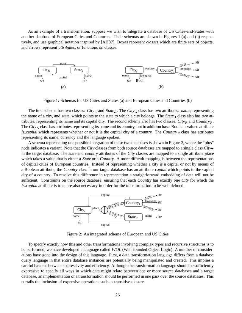
As an example of a transformation, suppose we wish to integrate a database of US Cities-and-States withanother database of European-Cities-and-Countries. Their schemas are shown in Figures 1 (a) and (b) respec-tively, and use graphical notation inspired by [AH87]. Boxes representclasseswhich are finite sets of objects,and arrows representattributes, or functions on classes.
City State
state
capitalname name
str str
A A Cityname
str
Countrycountry
is-capital
Bool
languagename
currency
str
str
str
E E
(a) (b)
Figure 1: Schemas for US Cities and States (a) and European Cities and Countries (b)
The first schema has two classes:CityA andStateA. TheCityA class has two attributes:name, representingthe name of a city, andstate, which points to the state to which a city belongs. TheStateA class also has two at-tributes, representing its name and its capital city. The second schema also has two classes,CityE andCountryE.TheCityE class has attributes representing its name and its country, but in addition has a Boolean-valued attributeis capitalwhich represents whether or not it is the capital city of a country. TheCountryE class has attributesrepresenting its name, currency and the language spoken.
A schema representing one possible integration of these two databases is shown in Figure 2, where the “plus”node indicates a variant. Note that theCity classes from both source databases are mapped to a single classCityTin the target database. Thestateandcountryattributes of theCity classes are mapped to a single attributeplacewhich takes a value that is either aStateor aCountry. A more difficult mapping is between the representationsof capital cities of European countries. Instead of representing whether a city is a capital or not by means ofa Boolean attribute, theCountryclass in our target database has an attributecapitalwhich points to the capitalcity of a country. To resolve this difference in representation a straightforward embedding of data will not besufficient. Constraints on the source database, ensuring that eachCountryhas exactly oneCity for which theis capitalattribute is true, are also necessary in order for the transformation to be well defined.
City
Country
State
euro-city
us-city
place
languagename
currency
name
str
str
str
strname
str
capital
capital
T
T
T
Figure 2: An integrated schema of European and US Cities
To specify exactly how this and other transformations involving complex types and recursive structures is tobe performed, we have developed a language calledWOL (Well-founded Object Logic). A number of consider-ations have gone into the design of this language. First, a data transformation language differs from a databasequery language in that entire database instances are potentially being manipulated and created. This implies acareful balance between expressivity and efficiency. Although the transformation language should be sufficientlyexpressive to specify all ways in which data might relate between one or more source databases and a targetdatabase, an implementation of a transformation should be performed in one pass over the source databases. Thiscurtails the inclusion of expensive operations such as transitive closure.
26

Second, the size, number and complexity of schemas that may be involved in a transformation leads to a needfor partiality of rules or statements of a transformation language, and for the ability to reason with constraints.Schemas – especially in biomedical applications, which formed the initial impetus for this work – can be complex,involving many, deeply nested attributes. Values for attributes of an object in a target database may be drawn frommany different source database instances. In order to prevent the complexity of transforation rules becomingunmanageable, it is therefore necessary to be able to specify the transformation in a step-wise manner in whichindividual rules do not completely describe a target object.
Third, constraints can play a part in determining and optimizing transformations; conversely, transformationscan imply constraints on their source and target databases. Many of the constraints that arise in transformationsfall outside of those supported by most data-models (keys, functional and inclusion dependencies and so on) andmay involve multiple databases. It is therefore important that a transformation language be capable of expressingand interacting with a large class of constraints.
In the remainder of this paper, we describe the database transformation languageWOL and how transforma-tion programs are implemented in a prototype system calledMorphase1.
2 Data Model
The data model underlyingWOL supports object-identities, classes and complex data-structures. Formally, weassume a finite setC of classesranged over byC;C 0; : : :, and for each classC a countable set ofobject identitiesof classC. ThetypesoverC, ranged over by�; : : :, are given by the syntax
� ::= C j b j (a : �; : : : ; a : �) j hja : �; : : : ; a : � ji j f�g
Hereb are the built inbase types, such asintegerorstring. Class typesC, whereC 2 C, represent object-identitiesof classC. f �g are set types.(a1 : �1; : : : ; ak : �k) constructs record types from the types�1; : : : ; �n, whereashja1 : �1; : : : ; ak : �kji builds variant types from the types�1; : : : ; �n. A value of a record type(a1 : �1; : : : ; ak :
�k) is a tuple withk fields labeled bya1; : : : ; ak, such that the value of theith field, labeled byai, is of type�i.A value of a variant typehja1 : �1; : : : ; ak : �kji is a pair consisting of a labelai, where1 � i � k, and a valueof type�i.
A database schema can be characterized by its classes and their associated types. For example, the US Citiesand States schema has two classes representing cities and states. Each city has anameand astate, and eachstate has anameand acapital city. The set of classes for the schema is thereforeCA � fCityA;StateAg and theassociated types are
�CityA � (name: str; state: StateA); �StateA � (name: str; capital: CityA)
The European Cities and Countries schema has classesCE � fCityE;CountryEg and associated types
�CityE � (name: str; is capital: Bool; country : CountryE)
�CountryE � (name: str; language: str; currency: str)
3 The WOL Language
WOL is a Horn-clause language designed to deal with the complex recursive types definable in the model. Thespecification of a transformation written inWOL consists of a finite set ofclauses, which are logical statementsdescribing either constraints on the databases being transformed, or part of the relationship between objects in
1Morphasehas no relation to the god of slumber, Morpheus, rather it is an enzyme (-ase) for morphing data.
27

the source databases and objects in the target database. Each clause has the formhead(= body whereheadandbody are both finite sets ofatomic formulaeor atoms.
The meaning of a clause is that, if all the atoms in the body are true, then the atoms in the head are also true.More precisely, a clause issatisfiediff, for any instantiation of the variables in the body of the clause which makesall the body atoms true, there is an instantiation of any additional variables in the head of the clause which makesall the head atoms true.
For example, to express the constraint that the capital city of a state must be in that state one would write
X:state= Y (= Y 2 StateA;X = Y:capital; (C1)
This clause says that for any objectY occurring in the classStateA, if X is thecapitalcity of Y thenY is thestateof X. Here the body atoms areY 2 StateA andX = Y:capital, and the head atom isX:state= Y . Each atomis a basic logical statement, for example saying that two expressions are equal or one expression occurs withinanother.
Constraints can also be used to define keys. In our database of Cities, States and Countries, we would like tosay that a Country is uniquely determined by itsname, while a City can be uniquely identified by itsnameandits country. This can be expressed by the clauses
X = MkCityT (name= N; country= C) (= X 2 CityT ; N = X:name; C = X:country; (C2)
Y = MkCountryT (N) (= Y 2 CountryT ; N = Y:name; (C3)
MkCityE andMkCountryE are examples ofSkolem functions, which create new object identities associated uniquelywith their arguments. In this case, thenameof a City and thecountryobject identity are used to create an objectidentity for the City.
In addition to expressing constraints about individual databases,WOL clauses can be used to expresstrans-formation clauseswhich state how an object or part of an object in the target database arises from various objectsin the source and target databases. Consider the following clause
X 2 CountryT ; X:name= E:name; (T1)
X:language= E:language; X:currency= E:currency(= E 2 CountryE ;
This states that for everyCountryin our European Cities and Countries database there is a correspondingCountryin our target international database with the same name, language and currency.
A similar clause can be used to describe the relationship between EuropeanCity andCity in our target database:
Y 2 CityT ; Y:name= E:name; Y:place= inseuro-city(X) (= E 2 CityE ; X 2 CountryT ; (T2)
X:name= E:country:name;
Note that the body of this clause refers to objects both in the source and the target databases: it says that if thereis a City,E, in the European Cities database and a Country,X, in the target database with the samenameas thenameof thecountryofE, then there is a City,Y , in the target database with the samenameasE and withcountryX. (inseuro-city accesses theeuro city choice of the variant).
A final clause is needed to show how to instantiate thecapitalattribute ofCity in our target database:
X:capital= Y (= X 2 CountryT ; Y 2 CityT ; Y:place= inseuro-city(X); E 2 CityE ; (T3)
E:name= Y:name; E:state:name= X:name; E:is capital= True;
Notice that the definition ofCountryin our target database is spread over multipleWOL clauses: clause (T1) de-scribes a country’sname, languageandcurrencyattributes, while clause (T3) describes itscapitalattribute. Thisis an important feature ofWOL, and one of the main ways it differs from other Horn-clause logic based querylanguages such as Datalog or ILOG[HY90] which require each clause to completely specify a target value. It is
28

possible to combine clauses (T1), (T3) and (C3) in a single clause which completely describes how a Countryobject in the target database arises. However, when many attributes or complex data structures are involved, ora target object is derived from several source objects, such clauses become very complex and difficult to under-stand. Further if variants or optional attributes are involved, the number of clauses required may be exponentialin the number of variants involved. Consequently, while conventional logic-based languages might be adequatefor expressing queries resulting in simple data structures, in order to write transformations involving complexdata structures with many attributes, particularly those involving variants or optional attributes, it is necessaryto be able to split up the specification of the transformation into small parts involving partial information aboutdata structures.
4 Implementing WOL Programs
Implementing a transformation directly using clauses such as (T1), (T2) and (T3) would be inefficient: to inferthe structure of a single object we would have to apply multiple clauses. For example clauses (T1), (T3) and (C3)would be needed to generate a singleCountryobject. Further, since some of the transformation clauses, such as(T1) and (T3), involve target classes and objects in their bodies, we would have to apply the clausesrecursively:having inserted a new object intoCountryT we would have to test whether clause (T2) could be applied to thatCountryin order to introduce a newCityT object.
SinceWOL programs are intended to transform entire databases and may be applied many times, we tradeoff compile-time expense for run-time efficiency. Our implementation therefore finds, at compile time, an equiv-alent, more efficient transformation program in which all clauses are innormal form. A transformation clausein normal form completely defines an insert into the target database in terms of the source database only. Thatis, a normal form clause will contain no target classes in its body, and will completely and unambiguously de-termine some object of the target database in its head. A transformation program in which all the transforma-tion clauses are in normal form can easily be implemented in a single pass using some suitable database pro-gramming language. In our prototype implementationMorphase, the Collection Programming Language (CPL)[BDH+95, Won94] is used to perform the transformations.
Unfortunately, not all complete transformation programs have equivalent normal form transformation pro-grams. Further it is not decidable whether a transformation program iscomplete, that is whether it completelydescribes how to derive all objects in the target database from the source databases, or whether such an equiva-lent normal form transformation program exists. ConsequentlyMorphaseimposes certain syntactic restrictionson transformation programs to ensure that they arenon-recursive, which are easy to verify computationally andare satisfied by most natural transformations.
Within Morphase, constraints play an important role in completing as well as implementing transformations.Constraints on the target database can be used to complete transformations. As an example,Morphasewill com-bine clauses (T1) and (T3) with the key constraint onCountryT (C3) to generate a single clause which completelyspecifies how objects of classCountryT are generated from objects in the US Cities and States database.
In a similar way, constraints on the source databases can play an important part in optimizing a transformation.As an example, suppose the following rule was generated as a result of combining several incomplete clauses:
X = MkCountryT (N); X:language= L; X:currency= C (=
Y 2 CountryE; Y:name= N; Y:language= L; Z 2 CountryE ; Z:name= N; Z:currency= C
Implementing the clause as written would mean taking the product of the source classCountryE with itself, andtrying to bindY andZ to pairs of objects inCountryE which have the same value on theirnameattribute. How-ever if we had a constraint on the source database that specifiednameas a key forCountryE the clause could be
29

simplified to the following, more efficient, form
X = MkCountryT (N);X:language= L;X:currency= C (= Y 2 CountryE; Y:name= N;
Y:language= L; Y:currency= C
5 Conclusions
Data transformation and integration in the context of biomedical databases has been a focus of research at Pennover the past six years. Two languages and systems have resulted: CPL andWOL. CPL has primarily been usedfor querying multiple heterogeneous databases, and has proven extremely effective; it is also used to implementlanguage ofWOL transformations. While CPL – or OQL, or any other database query language with a sufficientlyrich data model – could be used for specifying transformations, they lack several useful features that are present inWOL. The first is a declarative syntax, which can be easily modified in response to schema evolution. The secondis the ability to specify partial clauses, which we have found extremely useful when many variants are involved(as is the case with ACeDB [TMD92]). The third is the ability to capture and reason about database constraints.Reasoning about constraints is critical when partial clauses are used, since target constraints are used to normalizetransformation programs. Complete details onWOL and Morphase can be found in [KDB95, Kos96, DK97].
TheWOL language has also been used independently by researchers in the VODAK project at Darmstadt,Germany, in order to build a data-warehouse of protein and protein-ligand data for use in drug design. This projectinvolved transforming data from a variety of public molecular biology databases, including SWISSPROT andPDB, and storing it in an object-oriented database, ReLiBase.WOL was used to specify structural transforma-tions of data, and to guide the implementations of these transformations.
References
[AH87] Serge Abiteboul and Richard Hull. IFO: A formal semantic database model.ACM Transactions on DatabaseSystems, 12(4):525–565, December 1987.
[BDH+95] Peter Buneman, Susan Davidson, Kyle Hart, Chris Overton, and Limsoon Wong. A data transformation systemfor biological data sources. InProceedings of 21st International Conference on Very Large Data Bases, pages 158–169,Zurich, Switzerland, August 1995.
[DK97] S.B. Davidson and A. Kosky. WOL: A language for database transformations and constraints. InProceedings ofthe International Conference of Data Engineering, April 1997.
[HY90] R. Hull and M. Yoshikawa. ILOG: Declarative creation and manipulation of object identifiers. InProceedings of16th International Conference on Very Large Data Bases, pages 455–468, 1990.
[KDB95] A. Kosky, S. Davidson, and P. Buneman. Semantics of database transformations. Technical Report MS-CIS-95-25, Department of Computer and Information Science, University of Pennsylvanic, Philadelphia, PA 19104-6389, July1995. To appear in Semantics of Databases, edited by L. Libkin and B. Thalheim.
[Kos96] Anthony Kosky.Transforming Databases with Recursive Data STructures. PhD thesis, Department of Computerand Information Science, University of Pennsylvania, Philadelphia, PA 19104, 1996. Available as UPenn TechnicalReport MS-CIS-96-18.
[TMD92] Jean Thierry-Mieg and Richard Durbin. ACeDB — A C. elegans Database: Syntactic definitions for the ACeDBdata base manager, 1992.
[Won94] Limsoon Wong.Querying Nested Collections. PhD thesis, Department of Computer and Information Science,University of Pennsylvania, Philadelphia, PA 19104, August 1994. Available as University of Pennsylvania IRCS Re-port 94-09.
30

Transforming Heterogeneous Data with Database Middleware:Beyond Integration
L. M. Haas R. J. Miller B. Niswonger M. Tork Roth P. M. Schwarz E. L. Wimmersflaura, niswongr, torkroth, schwarz, [email protected]; [email protected]
1 Introduction
Many applications today need information from diverse data sources, in which related data may be representedquite differently. In one common scenario, a DBA wants to add data from a new source to an existing warehouse.The data in the new source may not match the existing warehouse schema. The new data may also be partiallyredundant with that in the existing warehouse, or formatted differently. Other applications may need to integratedata more dynamically, in response to user queries. Even applications using data from a single source often wantto present it in a form other than that it is stored in. For example, a user may want to publish some informationusing a particular XML DTD, though the data is not stored in that form.
In each of these scenarios, one or more data sets must be mapped into a single target representation. Neededtransformations may include schema transformations (changing the structure of the data) [BLN86, RR98] anddata transformation and cleansing (changing the the format and vocabulary of the data and eliminating or at leastreducing duplicates and errors) [Val, ETI, ME97, HS95]. In each area, there is a broad range of possible transfor-mations, from simple to complex. Schema and data transformation have typically been studied separately. Webelieve they need to be handled together via a uniform mechanism.
Database middleware systems [PGMW95, TRV96, ACPS96, Bon95] integrate data from multiple sources.To be effective, such systems must provide one or more integrated schemas, and must be able to transform datafrom different sources to answer queries against these schema. The power of their query engines and their abilityto connect to several information sources makes them a natural base for doing more complex transformations aswell. In this paper, we look at database middleware systems as tranformation engines, and discuss when and howdata is transformed to provide users with the information they need.
2 Architecture of a DB Middleware System
To be a successful data transformation engine for scenarios such as the above, a database middleware system musthave several features. Since data these days comes from many diverse systems, it must provide access to a broadrange of data sources transparently. It must have sufficient query processing power to handle complex operations,and to compensate for limitations of less sophisticated sources. Some transformation operations (especially thecomplex ones) require that data from different sources be interrelated in a single query.
We use Garlic [C+95] to illustrate the ideas of this paper. Figure 1 shows Garlic’s architecture, which is typi-cal of many database middleware systems [PGMW95, TRV96, ACPS96]. Garlic is primarily a query processor;
Copyright 1999 IEEE. Personal use of this material is permitted. However, permission to reprint/republish this material for ad-vertising or promotional purposes or for creating new collective works for resale or redistribution to servers or lists, or to reuse anycopyrighted component of this work in other works must be obtained from the IEEE.Bulletin of the IEEE Computer Society Technical Committee on Data Engineering
31

Integrated Schema
QueryCompilation
QueryExecution
Data Sources
Clients
PersistentMetadata
Store
CLIO
Wrapper Interface
Wrapper Wrapper Wrapper Wrapper
Figure 1: Garlic architecture
it optimizes and executes queries over diverse data sources posed in an object-extended SQL. Garlic’s powerfulquery engine is capable of executing any extended SQL operation against data from any source. In both plan-ning and executing the query, it communicates withwrappersfor the various data sources involved in the query.Systems of this type have two opportunities to transform data: first, at the wrapper as the data is mapped fromthe source’s model to the middleware model (Section 3), and second, by queries or views against the middlewareschema (Sections 4 and 5). However, understanding how the data needs to be transformed is not always simple.The target representation is often only defined implicitly, by existing data. The data integration tool, Clio, shownhere and in more detail in Figure 4 will help users understand both their source’s data and the target representationand will assist them in creating a mapping between them.
3 Data Transformation at the Wrapper
The most basic tasks of a wrapper are a) to describe the data in its repository and b) provide the mechanisms bywhich users and the Garlic middleware engine may retrieve that data [RS97]. Since a data source is not likelyto conform to Garlic’s data model and data format, these two tasks imply that the wrapper must perform somelevel of schema and data transformation. To make the task of writing a wrapper as easy as possible, the Garlicwrapper architecture tries to minimize the required transformations, but wrappers can do more if desired.
The schemas of individual repositories are merged into the global schema via a wrapper registration step.In this step, wrappers model their data as Garlic objects, and provide aninterfacedefinition that describes thebehavior of these objects. The interface is described using the Garlic Definition Language (GDL), which is avariant of the ODMG Object Description Language [Cat96]. The interface definition provides an opportunity fora wrapper to rename objects and attributes, change types and define relationships even if the data source storesnone. For example, a relational wrapper might model foreign keys as relationships. Developing interface filesis typically not hard. For simple data sources, it may be best to generate them manually, as simple sources tendto have few object types, usually with fairly simple attributes and behavior. For more sophisticated sources, theprocess of generating an interface file can often be automated. For example, a relational wrapper can decideon a common mapping between the relational model and the Garlic data model (e.g. tuple = object, column =attribute), and provide a tool that automatically generates the interface file by probing the relational databaseschema. Wrappers must also provide animplementationof the interface which represents a concrete realizationof the interface. The implementation cooperates with Garlic to assign a Garlic object id (OID) to its objects, andmaps the GDL base types specified in the interface file to the native types of the underlying data source.
32

Oracle Database Wrapper
Relational Schema Garlic Schema
CREATE TABLE COUNTRIESfNAME VARCHAR(30) NOT NULL,CLIMATE VARCHAR (256),HIGHESTPEAK NUMBER(4),PRIMARY KEY(NAME) g
interface CountryTypefattribute string name;attribute string climate;attribute long highestpeak;
g;
CREATE TABLE CITIESfNAME VARCHAR(40) NOT NULL,COUNTRY VARCHAR(30) NOT NULL,POPULATION NUMBER(4),ELEVATION NUMBER(7,2),AREA NUMBER(7,2),PRIMARY KEY(NAME),FOREIGN KEY(COUNTRY)
REFERENCES COUNTRIESg
interface CityTypefattribute string name;attribute ref¡CountryType¿ country;attribute long population;attribute double elevation;attribute double area;
g;
Hotel Web Site Wrapper
interface HotelTypefattribute string name;attribute string street;attribute string city;attribute string country;attribute long postalcode;attribute string phone;attribute string fax;attribute short numberof rooms;attribute float avgroom price;attribute short class;void display location();
g;
Figure 2: Example of wrapper schemas
A hypothetical travel agency application illustrates the kinds of simple schema and data transformations thatwrappers can perform. The agency would like to integrate an Oracle database of information on the countries andcities for which it arranges tours with a web site that contains up-to-date booking information for hotels through-out the world. Figure 2 shows the orginal table definitions and the new interface definitions for the two rela-tional tables, and the interface file for the web site. The relational wrapper renamed theHIGHESTPEAKfieldto highest peak , and exposed the foreign keyCOUNTRYon theCITIES table as an explicit reference to aCountry object in the integrated database. The wrapper must be able to map requests for this attribute fromthe integrated database (in OID format) into the format expected by the relational database (as a string), andvice versa. In addition, thePOPULATION, ELEVATIONandAREAcolumns are all stored as typeNUMBER, yetpopulation has type long in the interface file, whileelevation andarea are doubles.
Each hotel listing on the web site contains HTML-tagged fields describing that hotel, and a URL to map thelocation of a particular hotel given its key. In the interface definition file, the HTML fields are represented asattributes of the Hotel object, each with an appropriate data type, though the web site returns all data in stringformat. The map capability is exposed as thedisplay-location method. It is the wrapper’s responsibilityto map names to the fields on the HTML page, and to convert data from strings into appropriate types.
4 Data Transformation in the Middleware
Views are an important means of reformatting data, especially for middleware, as the data resides in data sourcesover which the user has little control. Views provide the full power of SQL to do type and unit conversionsnot anticipated by the wrapper, merging or splitting of attributes, aggregations and other complex functions. InGarlic, object viewsallow further restructuring of data. It is frequently the case that the information about aparticular conceptual entity is part of several objects stored in various data sources. However, end-users want tosee a single object. An object view creates a new “virtual” object. This virtual object requires no storage sinceattributes are specified in a query rather than stored as base data. Every virtual object in Garlic is based on anotherobject (which could itself be a virtual object). Garlic uses the OID of the base object as the basis for the virtualobject’s OID, and provides a function, LIFT, to map the base OID to the virtual object’s OID.
One important reason to have virtual objects is to allow new behavior, i.e., new methods, to be defined forthese objects. Methods on views can also be used to “lift” methods on the base objects so that virtual objects canretain the base object’s functionality. Each method on a virtual object is defined by an SQL query. This queryhas access to the OID of the virtual object upon which the method is invoked via the keywordself, and can findthe OID of the base object, if needed. Methods return at most one item; otherwise a run-time error results.
33

interface citylisting Typefattribute string name;attribute string country;attribute float populationin millions;attribute float elevationin meters;attribute set¡ref¡HotelType¿¿ hotels;string find besthotel(IN long budget);
g;
create viewcity listing (name, country, populationin millions, elevationin meters, hotels, self)as selectC.name, C.country, C.population/1000000, C.elevation*0.3048,
MAKESET(H.OID), LIFT(’city listing’, C.OID)from Cities C, Hotels Hwhere C.name=H.city and UCASE(C.country-¿name)=H.countrygroup by C.name, C.country, C.population, C.elevation, C.OID
create methodfind besthotel(long budget)returnselecth1.namefrom unnest self.hotels h1where h1.class> all (selecth2.ratingfrom unnest self.hotels h2
where h2.name6 = h1.nameand h2.avgroom price� budget)and h1.avgroom price� budget
Figure 3: A sample view definition, with method
To register an object view in Garlic, the user must provide both an interface and an implementation (defini-tions of the view and any methods), as illustrated in Figure 3. This view, based on theCity objects defined inSection 3, createsCity Listing objects that have most of the attributes of aCity (but omit, for example,area), and an associated set of hotels. The view definition shows how these objects would be created. It usessome of Garlic’s object extensions to SQL, including a path expression to get the name of theCity ’s country,and a new aggregate function,MAKESET, that creates a set. Note that the LIFT function is used to compute theOID of the new virtual object. All the attributes of the virtual object must be included in the select list. The viewdefinition does some simple unit conversions using arithmetic functions, and uses the uppercase function to mapcountry names from the Oracle database to the names of countries in the Web source. More complex mappings(using translation tables or user-defined functions, for example) would also be possible. The method finds thebest hotel within a certain budget in the city on which it is invoked. The budget is an argument of the method.Note the use ofself to identify the correct set of hotels.
5 Data Mapping and Integration
We have described two components of Garlic that provide important data transformation facilities. The wrap-pers provide transformations required by the individual data sources, including data model translation and simpleschema and data transformations. Object views enhance the wrapper transformations with a general view mech-anism for integrating schemas. Object views support integrated cooperative use of different legacy databases,through query language based transformations, such as horizontal or vertical decomposition (or composition) ofclasses. Such transformations are required to integrate overlapping portions of heterogeneous databases.
In addition, we are working to provide a more powerful suite of schema and data transformations to permitintegration of schemas that exhibit schematic discrepancies, and matching of data objects that represent the samereal-world entity. Across heterogeneous data sources, different assumptions may have been made as to what datais time invariant and therefore appropriate to include as metadata rather than data. Data under one schema maybe represented as metadata (for example, as attribute or class names) in another. Such heterogeneity has beenreferred to asschematic heterogeneity. Traditional query languages are not powerful enough to restructure bothdata and metadata [Mil98, LSS96]. Likewise, in heterogeneous systems different representations of the sameentity in different sources are common. The same object may be identified by a different name in two sources,or even by a different key. Further, different entities may bear similar names in different sources. Identifyingequivalent objects and merging them also requires new, powerful transformations [ME97, HS95, Coh98].
In many tasks requiring data translation, the form of the translated data (its schema) is fixed or at least con-strained. In a data warehouse, the warehouse schema may be determined by the data analysis and business sup-port tasks the warehouse must support. As new data sources are added to the warehouse, their schemas must bemapped into the warehouse schema, and equivalent objects must be found and converged. Hence, the integrated
34

VIEW MERGE
VIEW
GENERATOR
CORRESPONDENCE
GENERATOR
VALIDITY
CHECK
GRAPHIC
USER
INTERFACE
SOURCE
SCHEMA
TARGET
SCHEMA
SCHEMA
READERS
CORRESPONDENCE ENGINE
MAPPING GENERATOR
META
QUERY
ENGINE
INPUT SCHEMAS
OUTPUT VIEW DEFINITIONS
Figure 4: Tool architecture
view is no longer synthesized via a set of transformations local to individual source databases. Rather, it mustbe possible to discover how a source’s schema components and data correspond to a fixed target schema andany existing data. Unlike traditional schema and data integration, this mapping process may require non-localtransformations of source schemas and data objects.
As an example, consider theHotel Type defined in Figure 2. Now imagine that a new source of hotel datahas become available, in which some of the data is redundant with the original web source, but most is not. Thisnew source of data has a collection for each country: one for France, one for China, etc. We wish to incorporatethis new source in such a way that the user sees only one collection of hotels. However, there are several obsta-cles to this goal. First, there is schematic heterogenity: in the new source the country name is metadata ratherthan an attribute value. Second, the system needs to be able to identify when hotels from the two sources arethe same. The same hotel may be identified by a different name in the two sources (e.g., “Hyatt St. Claire” vs.“St. Claire Hyatt”), and two different hotels may have the same name (e.g., “Holiday Inn Downtown” exists inmany cities). Metadata transformations that use higher order query language operators [Ros92] are needed forthe former, dynamic cleansing operations such as joins based onsimilarity [Coh98] for the latter.
6 Building the Integrated Schema
Converting from one data representation to another is time-consuming and labor-intensive, with few tools avail-able to ease the task. We are building a tool, Clio1, that will create mappings between two data representationssemi-automatically (i.e., with user input). Clio moves beyond the state of the art in several ways. First, while mosttools deal with either schema integration or data transformation, it tackles both in an integrated fashion. Second,it employs a full database middleware engine, giving it significantly more leverage than thead hoccollections oftools available today, or the lightweight “agents” proposed by others. Third, it will exploit the notion of a targetschema, and, where it exists, target data, to make the integration problem more tractable. Fourth, because themiddleware engine is being enhanced with more powerful transformation capabilities (Section 5) than most, itwill allow more complex transformations of both schema and data. Finally, it will use data mining techniques tohelp discover and characterize the relationships between source and target schema and data.
The tool has three major components (Figure 4): a set of Schema Readers, which read a schema and translateit into an internal representation (possibly XML); a Correspondence Engine (CE), which finds matching partsof the schemas or databases; and a Mapping Generator, which will generate view definitions to map data in the
1Named for the muse of history, so that it will deal well with legacy data!
35

source schema into data in the target schema. The CE has three major subcomponents: a GUI for graphical dis-play of the schemas and relevant data items, a correspondence generator, and a component to test correspondencesfor validity. Initially, the CE will expect the user to identify possible correspondences, via the graphical inter-face, and will provide appropriate data from source and target (using the meta query engine) for verifying thecorrespondences and identifying the nature of the relationship (again, initially relying on the user). This will bean iterative process. Over time, we anticipate increasing the “intelligence” of the tool using mining techniquesso that it can propose correspondences, and eventually, verify them.
Clio will be general, flexible, and extensible. We expect to have a library of code modules (e.g. Java Beans)for transformation operators, which the middleware engine will be able to apply internally. Open research issuesinclude what set of transformations are useful, and whether all transformations (particularly data cleansing) canbe done efficiently on the fly. We believe Clio’s modular design provides the flexibility required to experimentwith a wide range of transformation operators, allowing it to serve as a test bed for further research in this area.
References
[ACPS96] S. Adali, K. Candan, Y. Papakonstantinou, and V. S. Subrahmanian. Query caching and optimization in dis-tributed mediator systems. InProc. ACM SIGMOD, 25(2):137–148, Montreal, Canada, June 1996.
[BLN86] C Batini, M. Lenzerini, and S. Navathe. A comparative analysis of methodologies of database schema inte-gration.ACM Computing Surveys, 18(4):323–364, 1986.
[Bon95] C. Bontempo.DataJoiner for AIX. IBM Corporation, 1995.
[C+95] M. Carey et al. Towards heterogeneous multimedia information systems. InProc. of the Intl. Workshop onResearch Issues in Data Engineering, March 1995.
[Cat96] R. G. G. Cattell.The Object Database Standard – ODMG-93. Morgan-Kaufmann, San Mateo, CA, 1996.
[Coh98] W. Cohen. Integration of heterogeneous databases without common domains using queries based on textualsimilarity. In Proc. ACM SIGMOD, 27(2):201–212, Seattle, WA, June 1998.
[ETI] ETI - Evolutionary Technologies International. http://www.evtech.com/.
[HS95] M. Hernandez and S. Stolfo. The merge/purge problem for large databases. InProc. ACM SIGMOD,24(2):127–138, San Jose, CA, May 1995.
[LSS96] L. Lakshmanam, F. Sadri, and I. N. Subramanian. SchemaSQL - A Language for Interoperability in RelationalMulti-database Systems. InProc. of the Conf. on Very Large Data Bases (VLDB), Bombay, India, 1996.
[ME97] A. Monge and C. Elkan. An efficient domain-independent algorithm for detecting approximately duplicatedatabase records.Proc. of SIGMOD 1997 Workshop on Data Mining and Knowledge Discovery, May 1997.
[Mil98] R. J. Miller. Using Schematically Heterogeneous Structures.Proc. ACM SIGMOD, 27(2):189–200, Seattle,WA, June 1998.
[PGMW95] Y. Papakonstantinou, H. Garcia-Molina, and J. Widom. Object exchange across heterogeneous informationsources. InProc. IEEE Conf. on Data Engineering, pages 251–260, Taipeh, Taiwan, 1995.
[Ros92] K. A. Ross. Relations with Relation Names as Arguments: Algebra and Calculus.Proc. ACM PODS, pages346–353, San Diego, CA, June 1992.
[RR98] S. Ram and V. Ramesh. Schema integration: Past, present, and future. In A. Elmagarmid, M. Rusinkiewicz,and A. Sheth, editors,Management of Heterogeneous and Autonomous Database Systems. Morgan-Kaufmann, San Mateo, CA, 1998.
[RS97] M. Tork Roth and P. Schwarz. Don’t scrap it, wrap it! a wrapper architecture for legacy data sources. InProc. of the Conf. on Very Large Data Bases (VLDB), pages 266–275, Athens, Greece, August 1997.
[TRV96] A. Tomasic, L. Raschid, and P. Valduriez. Scaling heterogeneous databases and the design of DISCO. InProc. ICDCS, 1996.
[Val] Vality Technology Incorporated. http://www.vality.com/.
36

Repository Support for Metadata-based Legacy Migration
Sandra Heiler Wang-Chien Lee Gail MitchellGTE Laboratories Incorporated
40 Sylvan RoadWaltham, MA 02451
fsheiler,wlee,[email protected]
Abstract
Migrating legacy systems involves replacing (either wholly or partially) existing systems and databases,and complex transformations between old and new data, processes and systems. Correctly performingthese activities depends on descriptions of data, and other aspects of the legacy and new systems, and therelationships between them, i.e., metadata. Metadata repositories provide tools for capturing, transform-ing, storing, and manipulating metadata. They can also store information for managing the migrationprocess itself and for (re)use in other migrations. This paper discusses some of the issues that arise whenmigrating legacy systems and examines how repository technology can be used to address these issues.
1 Introduction
Modifications to software systems pose a constant challenge to businesses. The complexity of these modificationscan range from routine software maintenance (to fix errors, improve performance, or to add or change function-ality) to redefinition or replacement of entire business processes and, thus, of the software systems implementingthem. Replacing (either wholly or partially) an existing software system is alegacy migration: the extant soft-ware systems are the legacy; the transformation of data and procedures from the old to new system is a migrationprocess.
Two characteristics of legacy system migration create complexities that do not typically affect other softwaredevelopment:
� The legacy system provides an existing implementation of the target business process. Unlike new devel-opment, where the goal is to provide a working implementation at the end, a migration must maintain aworking implementation at each step of the way.
� Legacy systems and databases have established relationships with other systems/databases of the enter-prise. Data may be input to or output from other systems, or code may be reused in other applications.These relationships must be preserved or migrated during a migration effort.
For example, suppose an organization is migrating its financial systems to a new Enterprise Resource Plan-ning (ERP) implementation (for example, [1]), first replacing the general ledger programs, then replacing the tax
Copyright 1999 IEEE. Personal use of this material is permitted. However, permission to reprint/republish this material for ad-vertising or promotional purposes or for creating new collective works for resale or redistribution to servers or lists, or to reuse anycopyrighted component of this work in other works must be obtained from the IEEE.Bulletin of the IEEE Computer Society Technical Committee on Data Engineering
37

accounting system, finally replacing the payroll system. The new general ledger programs might use data pro-duced by the legacy accounts payable programs, and produce data that will be the new source of input for anexecutive reporting system. Similarly, the legacy HR system and new payroll system might use the same cal-culations for computing employee contributions to health insurance. At each stage the financial functions in thenew system and the remaining functions in the legacy systems must operate properly and interoperate with eachother. All the data used and produced by the financial systems must remain correct and consistent regardless ofthe migration stage and, of course, the systems processes must be correct and consistent at all stages.
Legacy system migration involves not just replacement of existing systems and databases, but complex map-pings between old and new data, processes and systems. In most cases, there are no complete replacements duringmigration and, even once fully migrated, new business process will be implemented with a mix of old and newdata and program code. As a result, legacy migration activities depend on descriptions of data, and other aspectsof the legacy and new systems, and the relationships between them. This metadata allows designers and engi-neers to better understand what the systems do, how they do it, and when they do it, as well as what data thesystems use or produce and where it comes from [2].
Supporting a legacy migration requires information about data and processes in the old and new systems. Inaddition, it requires information needed to move from one to the other and to integrate the remaining elements ofthe old with the elements in the new at each stage of the migration. This information can be represented as meta-data describing, for example, components (e.g., usage, functions, interface), data (e.g., source, format, units),code (e.g., source language, change history, versions), processes (e.g., implementations, workflows, require-ments), jobs (e.g., control language, performance statistics, hardware requirements), and relationships amongthe described elements ( e.g., instanceof, part of, computedby, dependson completionof).
Metadata repositories are designed specifically to store and manipulate these kinds of metadata. Repositorytechnology provides tools for capturing metadata by extracting it from existing systems and transforming it formanagement in the repository. A repository can also store information about the migration process itself that canbe (re)used in other migrations or maintenance, development,etc. projects.
In this paper we examine how repository technology can help with data transformation in the context of legacysystem migration. Although we concentrate here on the transformation of data, many of the ideas will also applyto ”transforming” procedures and processes. In the next section we outline the capabilities of available reposi-tory products. In Section 3 we present some of the issues related to data transformation when migrating legacysystems, and discuss how repository technology could be put in practice to facilitate migration. We conclude inSection 4, with a discussion of some additional advantages of using a repository during migration.
2 Repository Technology
A metadata repository consists of a set of software tools used for storage, search, retrieval, use and managementof metadata. The components of a repository system include a metadatabase and metadata management system,an extensible metamodel and modeling tools, and tools for populating the metadatabase and integrating and ac-cessing the metadata.The metadatabase and management system.The repository includes a database of metadata and a DBMS tomanage it. The repository DBMS provides standard database management facilities, such as persistent storage,data models, keys, certain types of queries, constraints and rules, transactions, data integrity and views, and alsoprovides additional features for dealing with the specific requirements of metadata. Metadata-specific featuresinclude built-in complex relationships, navigation, support for long-running transactions, versioning and config-uration management. Additional tools may be provided for defining and enforcing metadata security restrictions.
The repository DBMS is a logical system that may be physically instantiated as a single or distributed database.The repository database might be proprietary to a particular repository vendor, or implemented on top of standarddatabase products. Typically a proprietary database will be object-based to support the extensive navigation re-
38

quired to implement and track metadata relationships and versions. A non-proprietary repository might be tightlyintegrated with a particular database product, or might work with a variety of products via standard interfaces.Requirements for the repository DBMS differ from those for an ordinary DBMS; in particular, the size of a meta-database is typically orders of magnitude less than what must be supported by a regular DBMS.Extensible metamodel and modeling tools.A repository system provides a meta-metamodel describing thethings the repository needs to know about metadata (e.g., item types, attributes, relationships), and tools forbuilding metamodels to include application-specific metadata descriptions. Generally, a repository product willalso provide metamodels describing particular kind of metadata, for example, metamodels for different databaseschemas, software architecture specifications, or programming languages. Each metamodel provides built-in re-lationships specific to that type of metadata (e.g., a db2tablehas columndb2column). Metamodels can be mod-ified to adapt to changes in the set of tools or applications supported by the repository, or to the specific char-acteristics of those tools. A repository product usually provides modeling languages and other tools to facilitatecreation and modification of these metamodels.Tools for populating the metadatabase.The metadata stored in a repository will come from a variety of sources,so a repository provides tools for extracting metadata from these sources (e.g., schemas from databases or datastructure specifications from program code). Many software lifecycle management tools automatically store theiroutput in a repository so that metadata generated in one stage of the cycle can be accessed or augmented in otherstages of the cycle. For example, most CASE tools use a repository as a central location for capturing the con-nections between requirements, design and code. Other types of metadata sources do not provide an explicitrepresentation of the metadata, so tools may be provided to extract information from each type of source andgenerate metadata for the repository[4]. For example, descriptions of a legacy file system might be extractedfrom COBOL code. Static tools (scanners or parsers) extract metadata from databases, ! ! program code or othersources; dynamic tools (buses) interact with CASE and other software life-cycle support tools to populate therepository as part of the process of using the tool. A specific scanner or bus is needed to obtain metadata fromeach different type of metadata source.Tools for integrating metadata. Repositories support sharing metadata among different components or toolsby providing the ability to define global models and integrated views of metadata from heterogeneous systems.Views can be defined to allow access to any item in a metadata repository by any application or user (subjectto security restrictions) regardless of the originating source’s platform, language, application system, etc. Forexample, a repository could provide a single view of metadata from existing DB2 files on a mainframe database,from old COBOL copybooks, and from a newly designed data model based on a CASE tool run on a UNIXsystem using C++. In addition, model definitions can be used to specify associations among repository elementsthat indicate semantic similarities among elements from heterogeneous sources, e.g., that a user-id in an ERWIN-generated data model and a customerno in an Oracle database schema refer to the same data entities.Tools for accessing metadata.A repository product also includes tools to facilitate easy access to metadataand customization of the repository. These typically include a user interface (GUI), (often) a Web interface foraccessing metadata or Web tools for building such an interface, and APIs and/or a programming language for ac-cessing metadata management functions and building additional, application-specific functionality. In addition,access applications such as impact analysis use the navigational facilities of the repository to provide informationabout the data relationships. For example, impact analysis tools can be used to estimate the scope of changes ina software maintenance project and determine which modules will be affected by proposed changes.
3 Issues in Data Transformation for Legacy System Migration
Transforming data as part of legacy system migration raises issues that are not necessarily of concern when datatransformations are performed as part of other software engineering efforts. We focus here on three issues thattypically affect transformation in (or are exacerbated by) migration efforts: data rationalization, interoperabil-
39

ity, and process management. We discuss how these issues can be addressed (at least in part) using the tools ofmetadata repository technology.Data rationalization. Unlike new software development efforts, legacy system migration starts with data thatare part of the legacy systems delivering the specified functionality. An important aspect of migration planningis identifying appropriate sources of needed data and determining what transformations will be required to 1) becompatible with the new implementation, or 2) provide expanded functionality in the new system, and 3) supportcontinuing relationships with other parts of the legacy.
For example, suppose the payroll portion of the migration example of Section 1 moves from a variety ofdifferent local systems to a centralized system. This requires identifying appropriate sources for the employeeroster, time reporting, deductions, tax data, and so on. These sources may provide initial data for loading the newsystem, or may be used with wrappers as ongoing sources for the new system. In either case, the rationalizationprocess must determine what kinds of transformations are necessary to align both the syntax and semantics of thelegacy data items with the new requirements. Also, if multiple sources are available in the legacy for any part ofthe needed data, the data rationalization effort must determine which source or sources to transform.
Data rationalization can be supported by an inventory of source data elements, including data formats andmeanings, the uses of the data, and other relationships. Such an inventory could be built by loading the repository1
using data extraction tools that work with the input source types and the repository. It is important to note thatthe semantics of the data elements is intertwined with the functionality of the software components that create oruse the elements. Thus, metadata describing the software components that process the data elements is neededto complete the picture of what data sources are available to support data rationalization.
Theprocessof rationalizing data could also be supported using the repository. In particular, the metadatagenerated during the rationalization process – what decisions were made, why they were made, what items havebeen mapped, by whom, etc. – could be stored in the repository. This metadata could then be analyzed to de-termine discrepancies, for example, or referenced to assist in making further decisions about the data items orrelated items.Interoperability. In any migration, the new system may receive data feeds from the legacy, may become thesource of data for systems that are still part of the legacy, or may be required to trigger updates in the legacy. Forexample, the new payroll system may get its data feeds from the old time reporting system; the HR system (whichis not part of the migration) may depend on the new payroll system to update employee benefits information suchas vacation time. Since migration is an incremental process; the new implementation must exchange data withelements of the legacy in each delivered increment of the migrating system (including even the final product,because migration generally preserves parts of the legacy). Thus, support for interoperabililty requires detailedinformation describing the data elements of the legacy as well as the new system.
These data descriptions require both syntactic information (table layouts, units, encoding schemes, etc.) andsemantic information (what an element ”means”, where it comes from, how it’s produced, how it’s used, etc.)[3].For example, migrating payroll functions would require descriptions not only of the formats of employee recordsin the old HR system, but also descriptions of what constitutes a ”full-time” employee for benefits calculations,(e.g., appearance on the employee roster? having a particular form of employee number? reporting forty hoursof time worked? Are different definitions of ”full-time” employee used for different purposes?)
Similarly, as parts of the functionality are migrated, new and old code modules must interoperate. For exam-ple, old modules for computing employee paychecks may need to interoperate with new check-cutting modules.Later in the migration, the old paycheck computational modules may be replaced and all will have to continue tointeroperate with the old time reporting system. As another example, suppose the migration of the payroll systemproceeds by geographic region. As each region is converted, payroll data from the migrated regions must be com-bined with similar data from any remaining regions for computations done in the (new) tax withholding modules.Support for interoperability requires metadata describing the components of the legacy and the migrated systems.
1Assuming, of course, that the system information was not loaded into the repository during earlier development or maintenance.
40

The repository can store descriptions of interfaces and relationships among the components of the old and newsystems (e.g., between data elements and programs, or among software components that invoke one another) aswell as descriptions of the semantics of the old and new data (and code) in the various migration increments.The repository also supports management of metadata describing software configurations, data flows, error con-ditions, and job structures and schedules. This could be used, for example, to determine when needed data hasbeen updated or to obtain the transaction management requirements of the interoperating components.Process management.Management of the migration process can be supported by metadata repository tools thattrack and control the configurations that form each of the increments and the changes to components from oneincrement to the next. Each release in a migration must be configured in such a way that necessary relationshipsbetween migrated and legacy system functionality and databases are preserved through the various versions ofthe migrated system, and the retirement of legacy components. For example, suppose that part of the migrationprocess replaces project codes with a new coding scheme and that, in at least one system release, the projectaccounting modules use the old code and the time reporting modules use the new codes. This release cannotuse a common project validation scheme, and historical records will include different code types. Managing themigration will require recording when the code changes occur, and mappings of modules to validation schemes ineach version of a release. Testing procedures and error-correction mechanisms will also need to be aware of thevarious configurations. In addition, reporting systems will need to know the coding scheme changes to properlyannotate reports.
Resolving process management issues depends on having information that describes the data and softwarecomponents, and the business processes they implement. The information will change as the migration processunfolds, so resolving the issues requires not only up-to-date descriptions for each release version, but informationabout the process of change-when changes occur, the nature of the changes and the testing those changes trigger.In effect, what are needed are descriptions of the elements and the relationships among the elements, as wellas descriptions of the changes in the elements and the relationships among the changes. Repositories generallyprovide versioning and configuration management tools that can document the contents of releases at each stage,thus maintaining an historical record of the migration. Moreover, they provide impact analysis tools that canthen determine what elements were affected by each change and predict what will be affected by proposed ! !changes.
4 Conclusions
Metadata repositories have long been used by CASE tools to store and manage descriptions of system compo-nents, and by data administrators to document information stores. More recently, they are being used to supportintegration of various tools, databases and applications, and their use is expanding to managing metadata for manymore applications. We have shown how repositories can also be used to facilitate legacy migration by managinginformation about the existing and target systems and by providing tools to obtain, store, and analyze this infor-mation. As in new development efforts, design information in the repository can be used to generate some codeor for decision-making in later stages of a migration. In addition, this information may be used to generate testcases and the repository can be used to track the testing process and associated scripts.
Metadata repository technology also helps to address specific issues of data transformation in the context oflegacy migration:
1. Identifying appropriate sources of needed data and what transformations will be required to use that datain the migrated system is supported by data extraction tools and tools to assist with analyzing the metadata.The repository also provides a location for recording the relationships and transformations determined bya designer.
2. Interoperability among remaining legacy data (and systems) and migrated data is supported by a shared
41

model of data represented in the repository. In addition, descriptions of interfaces, component relation-ships, invocations, etc. can be stored in the repository, analyzed and used in designing and executing theintegration.
3. Management of the migration process itself can be supported by metadata repository tools that track andcontrol both the configurations that form each of the increments and the changes to components from oneincrement to the next.
A major advantage of using repository technology for storing metadata from a migration is the availability andusability of that information subsequent to the migration. For example, the information is useful in determiningwhen elements of the legacy can be retired. Repository impact analysis tools can trace from new modules anddata back to the legacy systems to see whether particular functions have been completely replaced (or replacedsufficiently) by the new systems. In addition, there is a continuing need for data from the migrated legacy to becombined with new data. The information gathered in the repository about the various systems and the migrationitself can be used to compile accurate historical reports. Also, information gathered during the migration can beused in further maintenance of the system (correcting errors, new releases, adding enhancements, etc.) and maybe useful in planning other migration projects.
Current applications of repository technology in software engineering typically address a single lifecyclestage or sequence of stages. Applications of repository technology to legacy migration tend to focus more broadlybecause they must include both the legacy and new systems and the components of each change as the migrationprocess proceeds. However, they too tend to address only lifecycle stages directly related to the migration. Bothapplications would benefit by using the repository to obtain information about the existing environment and tostore information during the project. We believe that significantly more benefits will accrue to the enterprise whenmetadata is shared across all stages of the lifecycle and across all projects. Our current work aims to engineersuch complete information asset management using a repository.
References
[1] ASAP World Consultancy, Using SAP R/3. Que Corporation, 1996.
[2] S. Heiler, ”Semantic Interoperability,” ACM Computing Surveys, 27(2), 1995.
[3] V. Ventrone and S. Heiler, ”Semantic Heterogeneity as a Result of Domain Evolution,” SIGMOD Record,December, 1991; reprinted in Multidatabase Systems: An Advanced Solution for Global Information Shar-ing, A. Hurson, M. Bright, and S. Pakzad (eds), IEEE Computer Society Press, Los Alamitos, CA, 1993.
[4] J. Q. Ning, A. Engberts and W. Kozaczynski, ”Automated Support for Legacy Code Understanding,” inCommunications of the ACM, 37(5), May 1994.
42

Independent, Open Enterprise Data Integration
Joseph M. Hellerstein, Michael Stonebraker, and Rick Cacciafjmh,mike,[email protected]
Abstract
Database researchers and practitioners have long espoused the virtues of data independence. When log-ical and physical representations of data are separated, and when multiple users can see different viewsof data, then the flexibility of usage, evolution, and performance of a database system is maximized. Thistenet has been lost in the marketing crush of Data Warehousing, which prescribes a tight coupling ofphysical representation and high-level usability.
In this paper we describe the Cohera Federated DBMS, which reintroduces data independence to theheterogeneous databases present in today’s enterprises. Cohera’s physical independence features providea scalable spectrum of solutions for physical design of enterprise-wide data. Its logical independencefeatures remove the distinction between data transformation and querying, by using industry-standardSQL99 as a unified open conversion framework.
1 Introduction
One of the major challenges and opportunities in corporate computing today is to facilitate the integration ofdata from multiple sources. As is well known, large enterprises have valuable information stored in a number ofsystems and formats: multiple relational databases, files, web pages, packaged applications, and so on. The rea-sons for the mix of technologies are also well known, including mergers and acquisitions, disjoint organizationalstructures, and the difficulty and expense of migrating from legacy systems.
The integration challenge has not escaped the attention of database vendors and researchers, and over the lastdecade there has been a flurry of effort to develop and market techniques fordata warehousing. The idea of datawarehousing is simple: in order to integrate data from multiple sources, the data is extracted from these sources,transformed into a common schema, and loaded into a single, unified database for the enterprise.
1.1 Warehousing: Dousing the Flame of Data Independence
From the dawn of relational databases in 1970, database wisdom has argued and repeatedly demonstrated thatdata independenceis key to the success of large, long-lived information stores. Codd originally justified therelational model by arguing that it
provides a means of describing data with its natural structure only - that is, without superimposingany additional structure for machine representation purposes. [This can] yield maximal indepen-
Copyright 1999 IEEE. Personal use of this material is permitted. However, permission to reprint/republish this material for ad-vertising or promotional purposes or for creating new collective works for resale or redistribution to servers or lists, or to reuse anycopyrighted component of this work in other works must be obtained from the IEEE.Bulletin of the IEEE Computer Society Technical Committee on Data Engineering
43

dence between programs on the one hand and machine representations and organization of data onthe other. [Codd70]
Today, data independence is typically decomposed into two aspects. Physical data independence divorces thestorage of data from its logical representation, maximizing the ability to tune and evolve the physical storage ofdata without affecting existing applications. Logical data independence divorces the underlying logical repre-sentation from the many different views presented to applications or users, maximizing the ability to customizethe presentation of information for purposes of convenience or security.
The lessons of data independence apply directly to an enterprise with its many data sources. The task ofintegrating multiple data sources should be divorced from the specifics of the physical integration - data shouldbe able to move and replicate in the enterprise without affecting applications. Similarly, the logical representationof the data should be malleable, to allow different users to see different views of all the data in the enterprise. Thisis particularly important in global enterprises, where different users will speak different languages, use differentcurrencies, support different business models, and care about different aspects of the enterprise.
Somehow, the message of data independence was lost in the crush of data warehouse marketing. Advocates ofwarehousing heard customers’ desire for a unifiedaccessto enterprise-wide data, and addressed it with uniformstorage: an inflexible centralized layout of all enterprise-wide data in a single system. The result is a chain ofexpensive, brittle software that is hard to configure, manage, scale and evolve. Warehouses and their associatedtools are unable to provide the physical data independence that allows flexible storage. Moreover, their, propri-etary data transformation frameworks are not reusable in query processing, which minimizes the opportunity forlogical data independence to provide different views to different users.
1.2 Federated Database Systems: Open Systems for Integration
By contrast, a goodFederated Database System(FDBS) provides full data independence. It en-sures flexibility in how the data is stored, repli-cated, and represented across the enterprise, al-lowing graceful and cost-effective evolution ofenterprise-wide databases. It also allows for mul-tiple logical views of an enterprise’s data, includ-ing user-customizable conversions of types, poli-cies, and schemas. An FDBS extends Codd’s vi-sion of data independence to the federation. Notethat a warehouse is a point in the FDBS designspace, where all data is physically unified, andconverted into a single logical representation oftypes and tables. (Figure 1).
IntegrationPhysical
None
None
OperationalData Stores(TP Systems)
Complete
Logical Integration
Complete Data Warehouse
Data Marts
Figure1: The logical and physical integration spectra.Without data independence, current solutions only of-fer points in the space. Cohera provides full logicaland physical independence, offering solutions span-ning this space.
In this paper we contrast the integration technology of the Cohera FDBS with the available solutions in thewarehouse space. We highlight the flexibility of the FDBS approach in enterprise-wide physical database design,and show how the high-performance techniques of data marts and warehouses can be leveraged as componenttechnologies in the federated space. We also consider the effects of proprietary warehouse transformation pack-ages on logical data independence, and contrast them with the open standard of SQL99.
2 Background: Buzzword Bingo
The research community has assimilated much of the warehousing lingo crafted by the business world. Beforediscussing the relevant issues, it is worthwhile to step back and have a fresh look at the terminology.
44

Data Warehouse:Consultant and industry pundit Bill Inmon is widely credited with coining this term. Hemeant by it a single, large system in which all an enterprise’s data over time would be stored. Most database re-searchers, looking at a data warehouse engine, would instantly identify the software as nothing more or less thana relational database management system, albeit one tuned for a particular workload.It is the workload that dis-tinguishes warehouses from standard DBMSs: warehouses are used in an append-only, query-mostly manner. Asa result, they include support for high-volume, large-scale decision-support queries, with a focus on techniqueslike bitmap indices [OQ97], pre-computed results (e.g. materialized views [GM95]), aggressive query rewriting[LPS+98], and parallel query processing [DG92]. Warehouse databases are often laid out in denormalized (“star”or “snowflake”) schemas, which favor high performance on queries, and low performance on updates.
Data Mart: Many organizations have found it too expensive and difficult to construct and maintain a com-plete data warehouse. In the absence of a single enterprise-wide data warehouse, the industrial consultants andvendors recommend constructing smallerdata marts. These are relational database systems that consolidate theinformation in a particular area of an enterprise. Like warehouses, marts are targeted to append-only, read-mostlyworkloads. Data marts are essentially small data warehouses, and use the same technologies for enhancing queryprocessing. Since marts are smaller than warehouses, they can also exploit some less-scalable but useful solu-tions, like the pre-computed multidimensional disk layouts used by some OLAP tools [DNR+97].
Who cares? Data warehouses and marts are nothing more or less than SQL database systems. So why thehype? Why do the database vendors discuss their “warehouse solutions” separately from their relational en-gines, when the software being used is identical? And what do warehouses and marts have to do with integratingenterprise-wide data? These questions are best answered by the marketing departments and consulting compa-nies, of course. But the technical issues are really twofold.
First, the sheer scale of data warehousing has pushed the envelope in the design of relational database en-gines. In order to process decision-support queries over terabytes, vendors and researchers have been forced todeploy a whole host of the query processing technologies developed in research and industry over the years. Theresulting systems represent impressive technical achievements, and have also produced well-known payoffs forsome customers, particular large retailers.
The second technical issue that arises in data warehousing is the challenge of data integration. In the nextsection we say more about this issue, and comment on technology options for addressing it.
3 Approaches to Data Integration
Any enterprise of even moderate size has multiple sources of data: accounting systems, personnel systems, cus-tomer databases, and so on. Typically these data sources are managed by separate pieces of software. In largeenterprises, there are often multiple data sources for each task, distributed geographically across the globe.
There are a number of products available for integrating the data in an enterprise. In this section we pro-vide an overview of the extant approaches to data integration, and argue the merits of replication for physicalindependence, and SQL99 for logical independence.
3.1 ETL: Extract-Transform-Load
A number of vendors sell so-called Extract-Transform-Load (ETL) tools, including Informatica, Sagent, Ardentand Platinum. ETL tools extract data from underlying data sources via both native DBMS gateways (e.g. fromrelational vendors, ISAM, etc.) and via standard interfaces like ODBC; they then load the data into a warehouseTypically, an ETL tool also provides a facility to specify data transformations, which can be applied as the datais being extracted from the data sources and loaded into the warehouse. Most tools come with a suite of standardtransformations (e.g., substring search/replace, units conversion, zip-code +4 expansion), and some extensibilityinterface for users to write their own transformations in a procedural language like C, C++ or Basic. Transfor-mations can typically be composed into a pipeline via a scripting tool or graphical interface.
45

A main problem with ETL tools is that they were designed to solve a niche problem - warehouse loading - andare not useful for general data transformation. In particular, they have proprietary transformation extensibilityinterfaces: customers must program in to a specialized API or in a specialized language. Beyond imposing alearning curve on IT departments, the tight-focus philosophy prevents reuse. Transformations developed for theETL tool cannot be reused in other data-conversion settings, particularly in ad hoc queries.
In essence,ETL tools display a lack of logical data independence: warehouse data can be transformed onlyduring a physical load, not during querying. Among other problems, this prevents users from having differentlogical views of warehouse data. For example, once worldwide sales data is converted into dollars in the ware-house, French users cannot retrieve their local sales in Euros.
3.2 Replication Servers
Data replication servers evolved before the advent of warehousing, and typically have different features than ETLtools. In essence, replication servers perform only the extract (E) and load (L) facilities of ETL tools, but in atransactionally secure and typically more efficient manner.
The goal of a replication server is to ensure that transactions committed in one DBMS are reflected in a sec-ond DBMS. This can be used in a warehouse environment, to ensure that updates to the operational stores arereflected in the warehouse. It can also be used to support more flexible replication than the “single warehouse”model. For example, replication can be used in a master-slave mode to provide warm standby copies of impor-tant sites or tables to ensure high availability. Master-slave mode can also be used to improve performance, byallowing queries in a distributed enterprise to run on “nearby” copies of data. Replication can also be used inpeer-to-peer mode, allowing updates to happen in multiple sites, with consistency ensured by conflict resolutionschemes. Unlike ETL tools, replication servers do not work under an assumption that all data is loaded into asingle warehouse. As a result, replication servers can be used to implement a flexible spectrum of physical repli-cation schemes.
Replication servers are useful tools for flexible data layout, and hence can coexist gracefully with federatedsystems that support physical data independence. Since replication servers do no data conversion, they provideno solutions for logical data indepence.
3.3 FDBMS and SQL99: Scalar and Aggregate Functions
A federated DBMS extracts data from underlying stores on demand, in response to a query request. Data transfor-mation is also done on demand by the FDBS. Transformations can be specified in the standard relational language,SQL99, extended with user-defined scalar and aggregate functions. Scalar functions operate a record at a time,taking a single record as input, and executing code to produce a modified record as output. In essence, scalarfunctions provide the utility to define simple conversions and combinations of columns. As an example, con-sider the following simple view that maps a table of customers from one data source, doing simple conversions:changing names into a single field of the form ’Lastname, Firstname’, names of states into a standard postal code,and zip codes into the zip+4 format (user-defined functions inboldface):
SELECT concat(capitalize(lastname), ”, ”,capitalize(firstname)) AS name,address, city,twoletter(state) AS state,zipfour (zip) AS zip
FROM customer;
This simple example demonstrates data conversion using user-defined scalar functions, producing one record ofoutput for each record of input.
By contrast, aggregate functions are used to “roll up” a number of rows into a single result row. With user-defined aggregation and grouping, SQL99 allows for queries that collect records into affinity groups, and produce
46

an arbitrary summary per group. For example, consider the following view, which uses a heuristic to removeduplicate entries from a mailing list (user-defined scalar functions inboldface, user-defined aggregates initalics):
SELECT std last(lastname) AS last,std first(firstname) AS first,typical order(order) AS stdorderFROM customer
GROUP BY address,Name LCD (firstname, lastname);
In this example, the NameLCD scalar function generates a “least common denominator” for a name (e.g. “Brown,Mr. Clifford and “Brown, Cliff are both reduced to “Brown, C”). All people at the same address with the same“LCD” name are grouped together. Then for each apparently distinct person in the cleansed list, a canonical out-put name is generated and a “typical” representative order is output based on all the person’s orders (e.g., basedon a classification algorithm, or a domain-specific rollup hierarchy).
Used aggressively, user-defined grouping and aggregation provide powerful features for data transformation:they can be used not only to convert units or replace substrings, but toaccumulate evidencebased on a numberof observations, and generate aconclusionbased on the evidence. In essence, SQL’s grouping facility provides ameans to gather evidence together, and SQL’s aggregation facility provides a means to specify conclusions thatcan be drawn.
The extensibility features of SQL99 present a natural, open interface for data transformation. Unlike the pro-prietary APIs and scripting languages of ETL tools, SQL is the standard interface for combining and transformingsets of data. With the extensibility of SQL99, these features can be used aggressively to do custom domain-specific transformation. More importantly, user-defined scalar and aggregation functions can be reused in otherSQL-based applications, which lets users leverage their investment in transformation logic for subsequent adhoc querying.Logical data independence requires that the transformation language and the query language beunified; hence SQL99 is the only natural solution.
4 Cohera: Flexible, Scalable Enterprise Data Federation
Cohera is a next-generation FDBS, based on the Mariposa research done at UC Berkeley [SAL+96]. Coherapresents the best features of an FDBS: it provides the expressive transformation power of SQL99 along witha full spectrum of data independence achieved by coordinating with multiple existing replication tools. Coheragoes well beyond the state of the art in federated databases, however; the economic model pioneered in Mariposaprovides the only available solution for seriousperformance scalabilityandadministrative scalability.
We proceed to discuss the advantages of FDBSs for enterprise integration, and of Cohera in particular.
4.1 FDBS + Replication>> ETL + Warehousing
Cohera recognizes that the key to physical data independence in a federation is to allow replication to be car-ried out aggressively and incrementally. This means that the FDBS should operate on any replica of a table, or(de)normalized replica of a schema. In order to facilitate this, Cohera interoperates seamlessly with a variety ofreplication tools, including market leaders from Sybase and Oracle. Cohera also includes a built-in replicator thatcan provide extra efficiency for certain replication tasks Regardless of the replication tool used, Cohera can takeadvantage of whatever replicas are available in the federation, and choose the most efficient replica dynamicallyfor each query.
By contrast, ETL and Warehousing provide a single point on the physical and logical spectra, breaking thenotion of data independence. As a result, warehouse shops need to invest in a centralized computing environ-ment large enough to hold all of an enterprise’s data. This requires an enormous investment in equipment andsoftware, and in the skilled administration required to keep such installations running. As one example from thereal world, a large telecommunications firm plans employs warehouses and finds good return on investment from
47

implementing them. However, before taking on the time, expense, and headcount to implement and support an-other warehouse, the firm wants to understand whether the data integration will be useful. A federated databasewill be used to deliver a logical view of multiple sources without requiring physical co-location. In effect, theFDBS delivers prototyping and migration facilities even for warehousing advocates.
An additional benefit of an FDBS over warehousing is the timeliness of data: an FDBS can provide access tolive data from operational stores, rather than outdated data fed into a warehouse once a day, week or month. Thetradeoff of timeliness and the impact on operational stores is one that can be made flexibly, depending on queryvs. transaction load; this is another benefit of the data independence afforded by FDBSs.
Finally, note that since FDBSs and replication use standard SQL99 as their transformation scheme, existingtools and techniques for materialized views can be integrated with the replication process. This allows FDBSs tospan the the logical/physical spectra of Figure 1, by allowing not only tables but also views (with SQL99 trans-formations!) to be either logical or physical.
4.2 Cohera>> 1st-Generation FDBS
Like Mariposa, Cohera integrates underlying data sources into acomputational economy, where data sourcescooperate in distributed query processing through a metaphor of “buying” and “selling” their services to eachother. Unlike Mariposa, Cohera explicitly focuses on federating heterogeneous systems.
When an SQL query is submitted to a Cohera site, a module at that site called thecontractortranslates thequery into a single-site execution plan. The contractor must consider each operation in the execution plan - e.g.scanning a table, or performing a join - and choose the most efficient data source to execute that operation. Todo this, it solicitsbids for each constituent part of the plan: for example it might solicit bids for the operation ofscanning a table called “sales”. This bid is sent to other Cohera sites (bidders) that manage their own underlyingstores. If a given bidder site manages a database with a copy of the “sales” table, it might choose to bid on theoperation. In this case it uses its own local rules to place a cost on the operation, and it ships its bid to the con-tractor. The contractor collects bids for all the individual operations, and constructs a distributed query plan thatminimizes the cost of the whole query.
This economic model provides enormous benefits over traditional FDBS designs. First, the economic modelensureslocal autonomyfor managers of databases in the federation, who can control bidding policy based onlocal constraints (e.g., “during 9-5 only bid on federation queries from the office of the CEO”.) Second, the eco-nomic model gives local managers the facility and incentive to participate in enterprise-wideload balancing: astandard bidding policy is to have the bid price be proportional to the product of work and local load average,which naturally spreads work to under-utilized servers. Third, the economic model providesscalable perfor-mance, by distributed the query optimization and scheduling process. First-generation FDBSs had centralizedoptimizers that needed to know the state of all machines in the federation in order to operate; this prevented scal-ing beyond a small size. Finally, federating the query optimization process providesadministrative scalability,by allowing local administrators to set costs and policies based on dynamic properties (load balance, time of day,installation of new hardware, etc.); the centralized optimizers of first-generation FDBSs limited the autonomy oflocal administrators, since the centralized optimizer had to have control to work correctly. A lack of autonomyrequires consensus among database administrators, which is politically (and often geographically) infeasible inan organization of any size.
As a final contrast between Cohera and earlier systems, note that the “open marketplace” in Cohera allowssites to be added and deleted over time. Coupled with replication, this facility gives an enterprise an incrementalpath to migrate along the spectrum of Figure 1. Note that a warehouse is not ready for production untilall thedata is loaded. By contrast, a federation can start out as a loose affiliation of a few operational stores, expandto include a denormalized query site (e.g. a data mart) to enhance some queries, and eventually grow to spanthe enterprise. This minimizes the management and cash flow needed at any point in time. It also allows forincremental upgrade of components, rather than a complete swap of old iron for new iron. Note that incremental
48

upgrade means that you are always buying a little of the latest hardware at the lowest price, rather than buying alot of today’s hardware at today’s prices to plan for tomorrow’s capacity.
5 Conclusion
Enterprise data integration is one of the most pressing problems in IT today, and a subject of much research in-terest. Cohera’s solution to this problem is to ensure full data independence: Cohera provides a flexible, scalableinfrastructure for enterprise-wide data storage, and a unified transform/query interface based on the open stan-dard of SQL99. Cohera’s unique scalability is the result of its economic computing model, which scales both inperformance and administrative complexity.
Bibliography
[Codd70] Codd, E.F. “A Relational Model of Data for Large Shared Data Banks.” Communications of the ACM13(6):377-387, 1970.[DG92] DeWitt, D. J. and J. Gray. “Parallel Database Systems: The Future of High Performance Database Sys-tems.” Communications of the ACM 35(6): 85-98, 1992.[DNR+97] Deshpande, P., J. F. Naughton, K. Ramasamy, A. Shukla, K. Tufte, amd Y. Zhao. “Cubing Algorithms,Storage Estimation, and Storage and Processing Alternatives for OLAP”. Data Engineering Bulletin 20(1):3-11,1997.[LPS+98] Leung, T.Y.C., H. Pirahesh, P. Seshadri and J. M. Hellerstein. “Query Rewrite Optimization Rulesin IBM DB/2 Universal Database”, in Stonebraker and Hellerstein (eds.), Readings in Database Systems, ThirdEdition, Morgan-Kauffman, San Francisco, 1998.[GM95] Gupta, A. and I. .S. Mumick. “Maintenance of Materialized Views: Problems, Techniques, and Appli-cations.”’ Data Engineering Bulletin, 18(2), June 1995.[OQ97] O’Neil, P. E. and D. Quass. “Improved Query Performance with Variant Indexes”. Proc. ACM SIGMODConference, Tucson, June, 1997, pp. 38-49[SAL+96] Stonebraker, M., P. M. Aoki, W. Litwin, A. Pfeffer, A. Sah, J. Sidell, C. Staelin, A. Yu. “Mariposa: AWide-Area Distributed Database System.” VLDB Journal 5(1): 48-63 (1996)
49

Supporting Retrievals and Updates in an Object/RelationalMapping System
Jack OrensteinNovera Software, Inc.
1 Overview
Novera Software, Inc. produces jBusiness, a pure-Java application server [NOVE]. Enterprise Business Objects(EBO) is an object/relational mapping system, which is part of jBusiness. This paper describes some of the trans-formations that EBO uses to provide transparent, high-performance database access to middle-tier Java applica-tions.
2 Business Objects
An EBO application manipulates business objects. Abusiness objectis an object representing some conceptrelevant to the application, whose state is obtained from an underlying relational database. Much of the code of anapplication can be expressed in terms of business objects. Other code relies on the EBO application programminginterface (API), and a collection library.
This section describes business objects, how they are mapped to Java objects, and how these objects aremapped to tables in a database. For more information, see [NOVE98].
2.1 Object Model
The EBO object model is extremely simple. Objects have identity. Objects have scalar properties, and may par-ticipate in one-to-one and one-to-many relationships.
A simple scalar propertyis mapped to a single column. Acomputedproperty is mapped to a SQL expres-sion, e.g. QUANTITY * UNIT PRICE. Anaggregateproperty is mapped to a SQL expression containing anaggregation operator, e.g. SUM(QUANTITY * UNITPRICE). Each property gives rise to methods for gettingand setting the property’s value. “Set” methods are useful even for computed and aggregate properties as theyallow the application to reflect changes due to actions by the application itself.
Foreign keys are mapped to one-to-one or one-to-many relationships. When a relationship is realized in Java,there are methods in the two participating classes. The methods generated depend on the cardinality of the re-lationship. For example, consider the one-to-many relationship between Employees and Departments. EBOwill generate the methods Department.getEmployees, which returns a collection, and Employee.getDepartment,
Copyright 1999 IEEE. Personal use of this material is permitted. However, permission to reprint/republish this material for ad-vertising or promotional purposes or for creating new collective works for resale or redistribution to servers or lists, or to reuse anycopyrighted component of this work in other works must be obtained from the IEEE.Bulletin of the IEEE Computer Society Technical Committee on Data Engineering
50
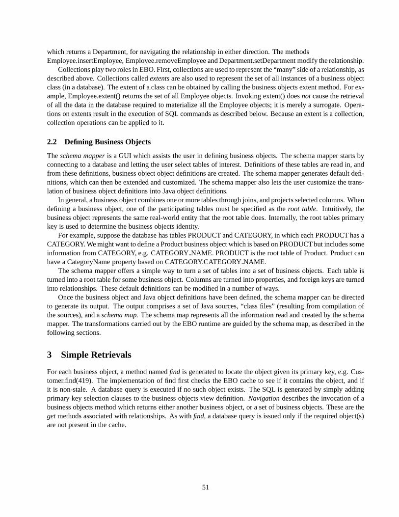
which returns a Department, for navigating the relationship in either direction. The methodsEmployee.insertEmployee, Employee.removeEmployee and Department.setDepartment modify the relationship.
Collections play two roles in EBO. First, collections are used to represent the “many” side of a relationship, asdescribed above. Collections calledextentsare also used to represent the set of all instances of a business objectclass (in a database). The extent of a class can be obtained by calling the business objects extent method. For ex-ample, Employee.extent() returns the set of all Employee objects. Invoking extent() doesnot cause the retrievalof all the data in the database required to materialize all the Employee objects; it is merely a surrogate. Opera-tions on extents result in the execution of SQL commands as described below. Because an extent is a collection,collection operations can be applied to it.
2.2 Defining Business Objects
Theschema mapperis a GUI which assists the user in defining business objects. The schema mapper starts byconnecting to a database and letting the user select tables of interest. Definitions of these tables are read in, andfrom these definitions, business object object definitions are created. The schema mapper generates default defi-nitions, which can then be extended and customized. The schema mapper also lets the user customize the trans-lation of business object definitions into Java object definitions.
In general, a business object combines one or more tables through joins, and projects selected columns. Whendefining a business object, one of the participating tables must be specified as theroot table. Intuitively, thebusiness object represents the same real-world entity that the root table does. Internally, the root tables primarykey is used to determine the business objects identity.
For example, suppose the database has tables PRODUCT and CATEGORY, in which each PRODUCT has aCATEGORY. We might want to define a Product business object which is based on PRODUCT but includes someinformation from CATEGORY, e.g. CATEGORYNAME. PRODUCT is the root table of Product. Product canhave a CategoryName property based on CATEGORY.CATEGORYNAME.
The schema mapper offers a simple way to turn a set of tables into a set of business objects. Each table isturned into a root table for some business object. Columns are turned into properties, and foreign keys are turnedinto relationships. These default definitions can be modified in a number of ways.
Once the business object and Java object definitions have been defined, the schema mapper can be directedto generate its output. The output comprises a set of Java sources, “class files” (resulting from compilation ofthe sources), and aschema map. The schema map represents all the information read and created by the schemamapper. The transformations carried out by the EBO runtime are guided by the schema map, as described in thefollowing sections.
3 Simple Retrievals
For each business object, a method namedfind is generated to locate the object given its primary key, e.g. Cus-tomer.find(419). The implementation of find first checks the EBO cache to see if it contains the object, and ifit is non-stale. A database query is executed if no such object exists. The SQL is generated by simply addingprimary key selection clauses to the business objects view definition.Navigationdescribes the invocation of abusiness objects method which returns either another business object, or a set of business objects. These are thegetmethods associated with relationships. As withfind, a database query is issued only if the required object(s)are not present in the cache.
51

4 View Expansion
4.1 View Table Queries and Base Table Queries
Consider the tables PRODUCT and CATEGORY, and the Product business object, ( described in section 2.2). Inthe terminology of the EBO implementation, PRODUCT and CATEGORY arebase tables- they are defined inthe database. EBO also has the concept of aview tablewhich corresponds to the view definition mapping Productto PRODUCT and CATEGORY. (When we use the term view we mean a definition stored in the EBO schemamap; we never refer to a view definition in the database. A view in the database is just another (base) table.)
There is one subsystem, thesqlsubsystem, that has an API for creating SQL queries, adding restrictions, jointerms, group by clauses, order by clauses, and so on. Those parts of EBO that translate retrieval operations intoSQL use this API to build up SQL queriesin terms of view tables. The sql subsystem is responsible for expandingthe view definitions to come up with SQL queries involving base tables.
4.2 Outerjoin Translation
Now assume PRODUCTand CATEGORYtables are connected by a foreign key from PRODUCT.CATEGORYIDto CATEGORY.CATEGORYID. Because the Product business object includes CATEGORY.CATEGORYNAME,Product’s view definition includes a join between the PRODUCT and CATEGORY, across the foreign key. Toprovide reasonable semantics to Java applications, the join must be an outer join. For example, iteration over theextent should locate all Products, including uncategorized ones, (i.e. PRODUCT rows with CATEGORYID =NULL). Such products are dropped by an inner join between PRODUCT and CATEGORY.
Outerjoin support by relational database systems is quite uneven. For this reason, we do not rely on nativeouterjoin capabilities. Instead, we simulate outerjoins using other techniques, e.g. a UNION of subqueries. Thisis quite expensive compared to an inner join, and in many situations the extra work is unnecessary maybe therereally arent any uncategorized products, and the user knows this. To avoid (simulated) outerjoins when possible,the schema mapper allows the user to declare, for each foreign key, that certain joins can be inner joins for thepurpose of materializing a business object.
4.3 Update Translation
Updates are handled differently due to the usual difficulties in updating through views. Whenever SQL updatecode is generated, (using the INSERT, DELETE or UPDATE commands), the updates are expressed directly interms of base tables; i.e., the sql subsystem is not used for view expansion.
4.4 Query Language
EBO provides a Java-like query language resembling Orion [KIM89] and ObjectStore query languages [OREN92].It was designed to be familiar to Java programmers rather than SQL programmers, and this is reflected in the syn-tax. It does, however, have capabilities similar to several SQL extensions (e.g. OQL [ODMG97]).
Example 1: Find Customers whose company name matches a given pattern.Query company name query = DbBlend.createQuery
(‘‘Customer customer; String pattern: ’’+
‘‘customer.getCompanyName.like(pattern)’’);
This query declares a Customer range variable, customer, and a free variable containing the pattern. The predi-cate locates those companies whose name matches the pattern. getCompanyName is a method for accessing theCompanyName property. (DbBlend is an earlier name for EBO. EBOs API still refers to this older name.)
52

Example 2: Find Customers still waiting for orders placed more than one year ago.Query major customers = DbBlend.createQuery
(‘‘Customer c; Date order date: c.getOrders[’’+
‘‘ Order o: o.getOrderDate � order date && ’’+
‘‘ o.getShipDate == null]’’);
This query contains a subquery which looks for qualifying Orders. A Customer appears in the result if it has atleast one qualifying Order.
5 Basic Query Translation
An EBO query is parsed, creating a parse tree in which leaves correspond to range variables, free variables, andliterals; and internal nodes represent operators such as navigation (the “dot” operator), comparisons, booleanoperators, and nested queries. Then a bottom-up scan of the parse tree is performed. At each node, some portionof a SQL query is created, using the API of the sql subsystem. The results of this generation are associated withthe node. When this traversal is complete, the root of the tree contains a complete SQL query.
6 Prefetch
Consider an order entry GUI that deals with Customers, Orders, OrderDetails, and Products. Given a Customer’sprimary key, the GUI might need the Customer’s Orders, each OrderDetail of each Order, and all Products refer-enced in any Order. All this information can be retrieved by navigation, using the methods Customer.getOrders,and Order.getOrderDetails, OrderDetail.getProduct. EBO provides an alternative. A description of a path canbe supplied when the query is created. If this is done, then the SQL generated is modified toprefetchthe relatedobjects along the path specified. Without prefetch hints, the number of SQL queries generated by the navigationis proportional to the number of objects retrieved. With prefetch, different queries are issued, and the number ofqueries is proportional to the length of the prefetch hints path description. (In the example above, there will beexactly four queries, one for each class: Customer, Order, OrderDetail and Product.) For example, here is codethat locates Customers whose company name contains the string “IBM”, and prints descriptions of their Orders:Query ibm customer query = dbblend.createQuery(‘‘Customer c: c.getCompanyName.like( n’’%IBM% n‘‘)’’);
for (ibm scan = Customer.extent().elements(ibm customer query);
ibm scan.hasMoreElements();) f
Customer customer = (Customer) ibm scan.nextElement();
for (order scan = customer.getOrders().elements();
order scan.hasMoreElements();) f
Order order = (Order) order scan.nextElement();
print order(order); g
g
Assuming execution begins with an empty cache, there is one query to the database to fetch the qualifying Cus-tomers, and then another query for each Customer to get that Customer’s Orders. The Order queries would looksomething like this:SELECT o.order id, o.order date, o.ship date
FROM ORDER o
WHERE o.customer id = ?
The value of the free variable (denoted by ?) is the primary key of the current Customer.
53

Two modifications are required to use prefetch. First, the navigation path needs to be described:
1. Create a path description starting at OrderPathSet customer to order = dbblend.createPathSet(‘‘Customer’’);
2. Extend the path by navigation through getOrders to an Order.customer to order.add(‘‘getOrders(Order)’’);
Then, add the path description as a second input to the createQuery method:Query ibm customer query = dbblend.createQuery
(‘‘Customer c:c.getCompanyName.like( n’’%IBM% n‘‘)’’,
customer to order);
Now, when the query is executed, both Customers and Orders will be retrieved and placed in the cache. Insteadof running multiple queries looking for the Orders rows with a given customer id, there will be one query to getthe Orders for all qualifying Customers:SELECT o.order id, o.order date, o.ship date
FROM ORDER o, CUSTOMER c
WHERE c.COMPANYNAME LIKE *%IBM%*
AND o.CUSTOMERID = c.CUSTOMERID
As a result, navigation from Customer to Order using customer.getOrders never needs to go to the database; theresult is already in the cache.
PathSets provide a very easy way to tune performance. Application developers can develop their businesslogic using queries and navigation. When performance problems are detected, they can often be addressed bysimply adding a PathSet to the queries, leaving the bulk of the business logic alone. If a query is created witha PathSet argument, then there is an additional phase in query translation. Following the creation of the initialSQL query a new query is generated for each step of each path represented by the PathSet.
7 Conclusions
EBO has proven successful in practice. Customers have quickly developed applications by mapping databaseschemas to business objects, writing applications in terms of business objects, and letting EBO take care of nearlyall interaction with the database. Typical applications involve 100-150 tables, mapped to a smaller number ofbusiness objects.
8 References
[KIM89] Won Kim, Nat Ballou, Hong-Tai Chou, Jorge F. Garza, Darrell Woelk: Features of the ORION Object-OrientedDatabase System. OO Concepts, Databases, and Applications 1989: 251-282[NOVE] Novera web site, http://www.novera.com.[NOVE98] Developing Enterprise Business Objects, Novera Software, Inc., December 1998.[ODMG97] The ODMG 2.0 Specification, Morgan Kaufmann, (1997).[OREN92] Jack A. Orenstein, Sam Haradhvala, Benson Margulies, Don Sakahara: Query Processing in the ObjectStoreDatabase System. SIGMOD Conference 1992: 403-412.
54

CALL FOR PAPERS The 16th International Conference on
Data EngineeringHoliday Day Inn on the Bay, San Diego, CA, USA
February 28 - March 3, 2000Sponsored by
IEEE Computer Society TC on Data Engineering
IEEE
SCOPEData Engineering deals with the use of en-gineering techniques and methodologies inthe design, development and assessment ofinformation systems for different comput-ing platforms and application environments.The 16th International Conference on DataEngineering will continue in its tradition ofbeing a premier forum for presentation of re-search results and advanced data-intensiveapplications and discussion of issues on dataand knowledge engineering. The mission ofthe conference is to share research solutionsto problems of today’s information societyand to identify new issues and directions forfuture research and development work.
TOPICS OF INTERESTThese include (but are not restricted to):
� Advanced Query Processing� Data Mining & Knowledge Discovery� Engine Technology (Storage Manage-
ment, Access Structures, Recovery, etc.)� Multimedia & Digital Libraries� New Departures (Mobile Agents, Embed-
ded Services, Personalization, etc.)� New Forms of Data (Spatial, Temporal,
etc.)� OLAP & Data Warehouses� Replication, Availability, & Consistency� System Administration, Ease of Use, and
DB Design� Web, Distribution, & Interoperation� Workflow, Transactions, & E-Commerce� XML & Metadata
IMPORTANT DATESAbstract submissions (electronic inAscii): June 9, 1999
Paper submissions (hardcopy orelectronic): June 16, 1999
Web page has electronic submission details
Panel/tutorial/industrial submissions:June 16, 1999Acceptance notification:October 15, 1999
Camera-ready copies:December 1, 1999
ORGANIZING COMMITTEEGeneral Chair: P.-A. (Paul) Larson, Microsoft, USA
Program Co-chairs: David Lomet, Microsoft, USAGerhard Weikum, Univ of Saarland, Germany
Panel Program Chair: Mike Carey, IBM Almaden, USATutorial Program Chair: Praveen Seshadri, Cornell Univ, USA
Industrial Program Co-Chairs: Anil Nori, Ventis, Inc, USAPamela Drew, Boeing, USA
PROGRAM VICE-CHAIRSAdvanced Query Processing Data Mining & Knowledge DiscoveryJeff Naughton, Univ of Wisconsin, USA Sunita Sarawagi, IBM Almaden, USA
Engine Technology System Admin, Ease of Use, & DB DesignHank Korth, Lucent - Bell Labs, USA Arnie Rosenthal, Mitre, USA
OLAP & Data Warehouses Workflow, Transactions, & E-commerceJeff Ullman, Stanford Univ, USA Hans Schek, ETH Zurich, Switzerland
XML and Metadata Web, Distribution, & InteroperationPhil Bernstein, Microsoft, USA Donald Kossmann, Univ of Passau, Germany
Multimedia & Digital Libraries Replication, Availability, & ConsistencyStavros Christodoulakis, Univ of Crete, Theo Haerder, Univ of Kaiserslautern,Greece Germany
New Forms of Data New Departures (Agents, Mobile, etc.)Beng Chin Ooi, National Univ of H. V. Jagadish, U Illinois - Urbana-Singapore, Singapore Campaign, USA
SUBMISSIONSPaper, panel, tutorial, or industrial-programsubmissions must be received by June 16,1999, 12:00 PM Pacific Time. Paper lengthmust not exceed 20 pages in not smaller than11 pt font.
For hardcopy submission, seven (7) copiesshould be sent to:David LometMicrosoft CorporationOne Microsoft WayRedmond, WA 98052-6399, USAE-mail: [email protected] electronic submission, please consult theconference web site at:http://research.microsoft.com/icde2000.
An abstract of no more than 300 words inASCII must be submitted at the conferenceweb site:http://research.microsoft.com/icde2000by June 9, 1999. The abstract submissionmust include the title of the paper, authors’
names, an e-mail address of the contact au-thor, a first and second preference among thetwelve topical areas, and whether the sub-mission is for the research paper, panel, tu-torial, or industrial program.
PANELS AND TUTORIALSThe research and industrial track will becomplemented by panels and tutorials. Pro-posals for each program should be sent tothe same address for paper submissions (seethere) byJune 16, 1999.
INDUSTRIAL PROGRAMThe conference program will include a num-ber of papers devoted to industrial develop-ments, applications, and experience in usingdatabases. Papers intended for this programshould be clearly marked as industrial trackpapers at the time of submission.
Conference web site: http://research.microsoft.com/icde2000

IEEE Computer Society1730 Massachusetts Ave, NWWashington, D.C. 20036-1903
Non-profit Org.U.S. Postage
PAIDSilver Spring, MD
Permit 1398


![IEEE Computer Society - Bulletin of the Technical Committee …sites.computer.org/debull/A07june/A07JUN-CD.pdf · 2010-03-22 · in self-managing database systems. Soror et al. [1]](https://static.fdocuments.in/doc/165x107/5f9f03928eaff26b301307b5/ieee-computer-society-bulletin-of-the-technical-committee-sites-2010-03-22.jpg)


