BULLETIN NO. SERVICE PARTS LIST 54-40-2620
1
69 38 40 48 55 64 68 58 60 66 67 17 3 7 50 54 59 30 6 29 6 MILWAUKEE ELECTRIC TOOL CORPORATION 13135 W. Lisbon Road, Brookfield, WI 53005 Drwg. 5 BULLETIN NO. 54-40-2620 SERVICE PARTS LIST FIG. PART NO. DESCRIPTION OF PART NO. REQ. 1 02-02-1100 4mm Ball (1) 2 02-04-1516 Ball Bearing (1) 3 --------------- Needle Bearing (1) 4 02-50-1640 Needle Bearing (1) 5 06-08-0015 3/16" Hex LH Drive Hub Bolt (1) 6 --------------- Pivot Pin (2) 7 --------------- Pin (1) 8 06-65-2995 Pin (1) 9 06-81-0065 10-32 x 2" Bolt (1) 10 06-82-3830 8-32 x 1/2" Csk Macine Screw (3) 11 06-82-3900 3/8" DG50 Thread Form Screw (2) 12 06-82-5316 8-32 x 1/2" Pan Hd. Taptite T-20 Screw (2) 13 06-82-5346 8-32 x 3/4" Pan Hd. Taptite T-20 Screw (5) 14 06-82-5362 8-32 x 1" Pan Hd. Taptite T-20 Screw (4) 15 06-82-7261 6-19 x 11/16" Pan Hd. Slt. Plast. T-15 (6) 16 06-82-7290 6-19 x 1-1/8" Pan Hd. Slt. Plast. T-15 (2) 17 14-09-0180 Crank Assembly (1) 18 10-15-0955 Warning Label (1) 19 12-20-2620 Service Nameplate Kit (1) 20 02-04-5130 Ball Bearing (1) 21 16-01-0025 Service Armature with Fan (1) 22 18-01-0070 Service Field (1) 23 22-18-0110 Carbon Brush Assembly - Black (1) 24 22-18-0135 Carbon Brush Assembly - Red (1) 25 22-20-0860 Brush Tube (2) 26 22-32-0400 Brush Spring Clip (2) 27 22-56-0025 Terminal Block Assembly (1) 28 23-66-0285 Switch (1) 29 28-14-0035 Gearcase Assembly - Left (1) 30 28-14-0060 Gearcase Assembly - Right (1) 31 31-11-0105 Barrel Cam (1) 33 31-44-2620 Handle - Left (1) 34 31-44-2625 Handle - Right (1) 35 31-50-0040 Motor Cage (1) 36 32-05-0025 Spiral Bevel Gear (1) 37 34-40-0035 O-Ring (1) 38 34-60-3700 Retaining Ring (1) 39 38-50-0260 Spindle (1) 40 --------------- Torsion Spring (1) 41 40-50-0595 Disc Spring (1) 42 40-50-0930 Compression Spring (1) 43 40-50-1090 Compression Spring (1) 44 40-50-8800 Extension Spring (1) 45 40-50-8840 Brush Spring (2) 46 42-40-0020 Spindle Pin Bushing (2) 47 42-40-0075 Spacer (1) 48 --------------- Front Cam (1) 50 --------------- Counter Balance Assemby (1) 51 43-06-0025 Metal Plate (1) 52 43-06-0030 Metal Plate (1) 53 43-56-0035 Orbit Slot (1) 54 --------------- Drive Hub (1) CATALOG NO. 2620-20 REVISED BULLETIN SPECIFY CATALOG NO. AND SERIAL NO. WHEN ORDERING PARTS 18 Volt Sawzall ® STARTING SERIAL NO. DATE July 2009 WIRING INSTRUCTION B58A EXAMPLE: Component Parts (Small #) Are Included When Ordering The Assembly (Large #). 0 00 SEE REVERSE SIDE FIG. LUBRICATION 2,36 Apply Type 'L' Grease, No. 49-08-4230 to the inside of Ball Bearing (2) and the inside of bearing in Gear Assembly (36). 36,59 Distribute 1 oz. of Type 'L' Grease on top of Gear Assembly (36) and at the Gear/Connection Rod (59) interface. 41,51,52 Apply Type 'L' Grease to all rubbing surfaces in the clutch: Disc Spring (41) and Metal Plates (51,52). 29,30 Distribute 3/4 oz. of Type 'B' Grease, No. 49-08-2000 in the Left and Right Gearcase halves (29,30), by Front Bushing (58) around the Spindle (39). 29,30 Coat Front Bushing pocket area of Gearcase halves with Type 'B' Grease prior to assembly. 60 Prior to assembly, saturate the Felt Seal (60) with a lightweight oil. 55 Lock Pin (55) to be coated with graphite prior to assembly. FIG. PART NO. DESCRIPTION OF PART NO. REQ. 55 44-60-1750 Lock Pin (1) 56 44-66-0280 Bearing Retaining Plate (1) 57 44-66-0285 Retaining Plate (1) 58 --------------- Front Bushing Carrier (1) 59 --------------- Connecting Rod (1) 60 --------------- Felt Seal (1) 61 45-06-0790 Seal (1) 62 45-12-0025 Gearcase Insulator (1) 63 45-16-0025 Shoe Assembly (1) 64 45-22-0175 Sleeve (1) 65 45-24-0045 Shuttle Switch (1) 66 --------------- Bushing Cap (1) 67 --------------- Washer (1) 68 38-50-6490 Front Bushing Carrier Assembly (1) 69 42-68-1200 Blade Clamp Assembly (See Page 5) (1) 71 44-66-5335 Bearing Retainer Plate (1) 72 02-04-0999 Ball Bearing (1) 73 45-28-0025 Grease Slinger (1) 74 32-60-0035 Pinion Gear (1) 75 42-55-2620 Accessory Carrying Case (1) Spindle (38) to be assembled with Lock Pin hole oriented as shown. Field (22) to be assembled with tapper to back and square groove to the top Press Needle Bearing (4) flush to sub-flush in Gearcase Half (30) NOTE: Pull Brush Tubes (25) back before removing or installing the Armature (21) to protect commutator. NOTE: Bolt (5) is left hand thread. SEE PAGE 5 for special service note on the Blade Clamp Assy. SEE ADDITIONAL SERVICE NOTES ON FOLLOWING PAGES
Transcript of BULLETIN NO. SERVICE PARTS LIST 54-40-2620
69 38 40 4855 64
68 58 6066 6717 3 7 50
54 59
30 6
29 6
MILWAUKEE ELECTRIC TOOL CORPORATION13135 W. Lisbon Road, Brookfi eld, WI 53005
Drwg. 5
BULLETIN NO.54-40-2620SERVICE PARTS LIST
FIG. PART NO. DESCRIPTION OF PART NO. REQ. 1 02-02-1100 4mm Ball (1) 2 02-04-1516 Ball Bearing (1) 3 --------------- Needle Bearing (1) 4 02-50-1640 Needle Bearing (1) 5 06-08-0015 3/16" Hex LH Drive Hub Bolt (1) 6 --------------- Pivot Pin (2) 7 --------------- Pin (1) 8 06-65-2995 Pin (1) 9 06-81-0065 10-32 x 2" Bolt (1) 10 06-82-3830 8-32 x 1/2" Csk Macine Screw (3) 11 06-82-3900 3/8" DG50 Thread Form Screw (2) 12 06-82-5316 8-32 x 1/2" Pan Hd. Taptite T-20 Screw (2) 13 06-82-5346 8-32 x 3/4" Pan Hd. Taptite T-20 Screw (5) 14 06-82-5362 8-32 x 1" Pan Hd. Taptite T-20 Screw (4) 15 06-82-7261 6-19 x 11/16" Pan Hd. Slt. Plast. T-15 (6) 16 06-82-7290 6-19 x 1-1/8" Pan Hd. Slt. Plast. T-15 (2) 17 14-09-0180 Crank Assembly (1) 18 10-15-0955 Warning Label (1) 19 12-20-2620 Service Nameplate Kit (1) 20 02-04-5130 Ball Bearing (1) 21 16-01-0025 Service Armature with Fan (1) 22 18-01-0070 Service Field (1) 23 22-18-0110 Carbon Brush Assembly - Black (1) 24 22-18-0135 Carbon Brush Assembly - Red (1) 25 22-20-0860 Brush Tube (2) 26 22-32-0400 Brush Spring Clip (2) 27 22-56-0025 Terminal Block Assembly (1) 28 23-66-0285 Switch (1) 29 28-14-0035 Gearcase Assembly - Left (1) 30 28-14-0060 Gearcase Assembly - Right (1) 31 31-11-0105 Barrel Cam (1) 33 31-44-2620 Handle - Left (1) 34 31-44-2625 Handle - Right (1) 35 31-50-0040 Motor Cage (1) 36 32-05-0025 Spiral Bevel Gear (1) 37 34-40-0035 O-Ring (1) 38 34-60-3700 Retaining Ring (1) 39 38-50-0260 Spindle (1) 40 --------------- Torsion Spring (1) 41 40-50-0595 Disc Spring (1) 42 40-50-0930 Compression Spring (1) 43 40-50-1090 Compression Spring (1) 44 40-50-8800 Extension Spring (1) 45 40-50-8840 Brush Spring (2) 46 42-40-0020 Spindle Pin Bushing (2) 47 42-40-0075 Spacer (1) 48 --------------- Front Cam (1) 50 --------------- Counter Balance Assemby (1) 51 43-06-0025 Metal Plate (1) 52 43-06-0030 Metal Plate (1) 53 43-56-0035 Orbit Slot (1) 54 --------------- Drive Hub (1)
CATALOG NO. 2620-20
REVISED BULLETINSPECIFY CATALOG NO. AND SERIAL NO. WHEN ORDERING PARTS
18 Volt Sawzall®
STARTING SERIAL NO.
DATEJuly 2009
WIRING INSTRUCTIONB58A
EXAMPLE:Component Parts (Small #) Are Included When Ordering The Assembly (Large #).
000
SEE REVERSE SIDE
FIG. LUBRICATION 2,36 Apply Type 'L' Grease, No. 49-08-4230 to the inside of Ball Bearing (2) and the inside of bearing in Gear Assembly (36). 36,59 Distribute 1 oz. of Type 'L' Grease on top of Gear Assembly (36) and at the Gear/Connection Rod (59) interface.
41,51,52 Apply Type 'L' Grease to all rubbing surfaces in the clutch: Disc Spring (41) and Metal Plates (51,52).
29,30 Distribute 3/4 oz. of Type 'B' Grease, No. 49-08-2000 in the Left and Right Gearcase halves (29,30), by Front Bushing (58) around the Spindle (39).
29,30 Coat Front Bushing pocket area of Gearcase halves with Type 'B' Grease prior to assembly.
60 Prior to assembly, saturate the Felt Seal (60) with a lightweight oil.
55 Lock Pin (55) to be coated with graphite prior to assembly.
FIG. PART NO. DESCRIPTION OF PART NO. REQ. 55 44-60-1750 Lock Pin (1) 56 44-66-0280 Bearing Retaining Plate (1) 57 44-66-0285 Retaining Plate (1) 58 --------------- Front Bushing Carrier (1) 59 --------------- Connecting Rod (1) 60 --------------- Felt Seal (1) 61 45-06-0790 Seal (1) 62 45-12-0025 Gearcase Insulator (1) 63 45-16-0025 Shoe Assembly (1) 64 45-22-0175 Sleeve (1) 65 45-24-0045 Shuttle Switch (1) 66 --------------- Bushing Cap (1) 67 --------------- Washer (1) 68 38-50-6490 Front Bushing Carrier Assembly (1) 69 42-68-1200 Blade Clamp Assembly (See Page 5) (1) 71 44-66-5335 Bearing Retainer Plate (1) 72 02-04-0999 Ball Bearing (1) 73 45-28-0025 Grease Slinger (1) 74 32-60-0035 Pinion Gear (1) 75 42-55-2620 Accessory Carrying Case (1)
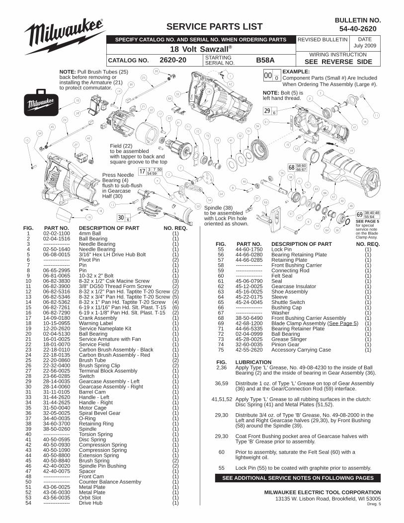
Spindle (38) to be assembled with Lock Pin hole oriented as shown.
Field (22) to be assembled with tapper to back andsquare groove to the top
Press Needle Bearing (4)fl ush to sub-fl ushin GearcaseHalf (30)
NOTE: Pull Brush Tubes (25) back before removing or installing the Armature (21) to protect commutator.
NOTE: Bolt (5) is left hand thread.
SEE PAGE 5for special service noteon the Blade Clamp Assy.
SEE ADDITIONAL SERVICE NOTES ON FOLLOWING PAGES