BULLETIN 49103 ElectricalPartManuals . com www . . com …€¦ · · 2014-03-24File these...
14
GENERAL INSTRUCTIONS FOR TYPE SHV-SO AND SHV-160 · l MULTUMITE SWITCHGEAR l l J 6000 VOLT-600, 1200 AND 2000 AMPERE INSTALLATION, OPERATION AND MAINTENANCE BULLETIN 49103 I-T-E CIRCUIT BREAKER COMPANY 19TH AND HAMILTON STREETS PHILADELPHIA 30, PA. www . ElectricalPartManuals . com www . ElectricalPartManuals . com
Transcript of BULLETIN 49103 ElectricalPartManuals . com www . . com …€¦ · · 2014-03-24File these...

GENERAL INSTRUCTIONS FOR
TYPE SHV-SO AND SHV-160
· l MULTUMITE SWITCHGEAR
l
l J
6000 VOLT-600, 1200 AND 2000 AMPERE
INSTALLATION, OPERATION
AND MAINTENANCE
BULLETIN 49103
I-T-E CIRCUIT BREAKER COMPANY 19TH AND HAMILTON STREETS
PHILADELPHIA 30, PA.
www . El
ectric
alPar
tMan
uals
. com
www . El
ectric
alPar
tMan
uals
. com

INTRODUCTION
Instructions for installation, operation and maintenance of type 5HV multumite switchgear are furnished with each shipment.
These instructions should be read carefully and used as a guide during installation and initial operation. File these instructions in a readily accessible place together with drawings and descriptive data of the
switchgear. The use of these instructions will facilitate proper maintenance of the equipment and prolong its life and usefulness.
SCOPE OF INSTRUCTIONS
These instructions are general. They cover requirements for installation as applied to all multumite switchgear of the 5HV-50 and 5HV-150 classification. A typical example is shown in Fig. I.
Specific information on particular applications is furnished in the form of job drawings.
I. Front view and single line diagram showing high voltage connections.
2. Detailed wiring diagrams for each unit. 3. Section drawings for each unit.
4. Special construction details.
Front view diagrams are cross referenced with wiring diagram and section drawings.
TRANSPORTATION
Prior to shipment. the 5HV switchgear undergoes careful factory inspection and crating. Each crate is plainly marked at convenient places with crate number and position. When size or other reasons make it necessary to divide the equipment for shipment, the unit number of the particular equipment enclosed is also marked on the crate, along with its weight. The removable elements are shipped in individual crates.
Immediately upon receipt of the switchgear, examine for any damage or loss sustain� during transportation. Check the contents against the pack· ing list before discarding any packing material.
If there is any shortage notify the nearest I-T-E Circuit Breaker Company representative at once.
The I-T-E Circuit Breaker Company is not responsible for damage after delivery of shipment to the carrier. However, if the company is notified of such claims, it will furnish forms to facilitate securing any adjustments. If damage to the shipment indicates rough handling, claim for damage should be filed at once with the carrier and the 1-T-E Circuit Breaker Company promptly notified.
UNLOADING AND HANDLING
The switchgear housings are crated and shipped in groups of one to six units. Each group is provided with heavy wooden skids. The remainder is crated for protection. Unloading and handling at the site is usually done by placing rollers under the skid. To avoid distortion to the switchgear, any force to move the structures should be applied to the skid by means of crowbar, block and tackle, crane, etc.
STORAGE
Remove crating from the switchgear units, but leave each group on its skid for subsequent moving. Uncrate removable elements and accessories. Observe the following precautions:
I. Check for missing or damaged parts. 2. Store in clean dry place. 3. Cover parts susceptible to rust with heavy oil
or grease. 4. Cover with heavy wrapping paper to keep
dirt or dripping water from entering. Dirt or moisture may foul working parts or deteriorate contacts and insulation.
TABLE OF CONTENTS
Page Page UNLOADING AND HANDLING I STANDARD CONSTRUCTION (Continued)
INSTALLATION OF HOUSINGS Primary Disconnecting Device .. 6 General 3 Secondary Disconnecting Devices 6 Preparation of Floor 3 Ground Bus and Contacts 7 Assembling the Housings . . . . . . . . 3 Control Bus 7 Connections
REMOVABLE ELEMENTS Primary Cables 4 Ground Bus 4 General 8 Control Source 4 Installation of Removable Element. 9 Bus Bar Between Groups 5 Removing Element from Housing 9
Testing 5 HOW TO PUT THE SWITCHGEAR Final Inspection . 5 IN SERVICE
STANDARD CONSTRUCTION General 11 Shutters 6 Safety Precautions 11 Bus Insulation 6 Procedure 11 0
' .
www . El
ectric
alPar
tMan
uals
. com
www . El
ectric
alPar
tMan
uals
. com

GENERAL INSTRUCTIONS FOR
TYPE 5HV-50 AND 5HV-150 MULTUMITE SWITCHGEAR
5000 VOLT-600. 1200 AND 2000 AMPERE
INSTALLATION, OPERATION AND MAINTENANCE
UNLOADING AND HANDLING
The following is a recommended method for unloading and handling type SHV multumite switc4gear housing�.
INDOOR INSTALLATION
l. Prior to uncrating, the switchgear should be moved near installation site. This operation may be completed by raising switchgear shipping skid with track jacks to allow rollers to be placed under skid.
2. After switchgear housings have been moved to site, uncrate and remove lag screws located inside of housings. Raise housings by placing jacks under both shipping channels under main housings as shown in Figure l . Caution: Do not
apply jacks to the housings at any other point except the channels. Raise housinqs evenly and JUSt enough to position rollers. Repeat opera-
FIG. 1-METHOD OF RAISING SWITCHGEAR BY USE
! I �
OF JACKS-ROLLERS IN PLACE
FIG. 2-SWlTCHGEAR LOWERED ON ROLLERS PRIOR TO MOVING ON TO TRACK TIMBER
tion at other end of housing, so that rollers are equally distributed under housings.
3. Place timber to extend longitudinally from skid as shown in Figure 2. While crew push switchgear, Figure 3, have one man insert roller as shown in Figure 4. Continue this operation until housing is entirely on track timber.
4. For lateral moving, raise housings by jacks and remove track timber. Place rollers laterally with steel channels resting on rollers as shown in Figures 5 and 6. Move housings over mounting site and proceed with fastening of housings.
FIG. 3-LONGITUDINAL MOVING OF SWITCHGEAR FROM SHIPPING SKID
FIG. 4-METHOD OF APPLYING ROLLERS AS SWITCH
GEAR PROGRESSES ONTO TRACK TIMBER
Page 1 www . El
ectric
alPar
tMan
uals
. com
www . El
ectric
alPar
tMan
uals
. com

:·,� .,�:
OUTDOOR INSTALLATION
5. Outdoor installation is handled similar to that indoors. To raise housings above projecting mounting channel sills, heavy wood beams should be used the same height as the sills when using rollers.
FIG. 5-SWITCHGEAR RAISED WITH ROLLERS AND CHANNELS IN PLACE PRIOR TO LATERAL MOVING
.. •
f. •
FIG. 6-/ACKS REMOVED AND SWITCHGEAR READY FOR LATERAL MOVING
Page2
'•
0
www . El
ectric
alPar
tMan
uals
. com
www . El
ectric
alPar
tMan
uals
. com

_..,
( .
INSTALLATION OF HOUSINGS GENERAL
Before attempting any installation operations consult all drawings furnished by the 1-T-E Circuit Breaker Company for the particular order. -These drawings are in the form of floor plans. co�lduit locations, front, rear, and side views, primary and secondary wiring and a detailed summary of the equipment furnished. A section of housings consisting of approximately six units or less are shipped complete on a single skid. Larger switchboards are divided in sections for shipment and each section is on its own skid. In addition each section is provided with two three inch shipping channels running the full length of the section. The purpose of these channels is to reinforce the switchgear for shipment, and to provide means of moving the section into position by use of rollers. The floor plans indicate recesses in the floor to receive these channels.
PREPARATION OF FLOOR
Floor plan drawings are supplied for each installation and frequently the channel iron sills are shipped in advance of the switchgear. Typical floor plan drawings are not enclosed since they usually vary with each installation due to length and ar· rangement of housings.
Channel iron sills may be cast in concrete. It is important that these sills be straight and level their full length. and correctly spaced. To insure this condition, it is recommended that ties be bolted between the sills at various intervals after which the lower flange of the sill be shimmed to proper height. Temporary bolts should be inserted in all tapped holes while grouting, to prevent filling or damage to the threads.
Where necessary load and secondary (control) conduits should be installed before the installation of the housings. Location and number of the conduits is given on the plan drawings accompanying each order. These conduits should not extend above the station floor level. Take precautions to plug conduit openings before pouring cement.
The concrete floor in front of the housings should be smooth to facilitate the handling of the removable elements. The finished floor level should be lfa inch above the channel sills so that the removable element will roll evenly into the housing. A Va inch thick strip attached to the channel sills will permit troweling flush when the cement is poured. The cement should be prepared in accordance with instructions issued by the Portland Cement Association. available at their offices in the large cities.
Photo 13540-R
FIG. 1-TYPE SHV-150 MULTUMITE SWITCHGEAR
ASSEMBLING THE HOUSINGS
When the floor has been properly prepared, assembly of the switchgear may be started. Sections of the housings may be moved on the1r skids adjacent to final positions. They may be moved from skids to final location by putting rollers under the shipping channels.
If the switchgear consists of a number of sections. the center sections should be installed first. and the remaining sections added at each end. When the first section is in position, it should be checked for distortion in shipment. This may be done by dropping a plumb bob from the center of the front and rear doors. If the structures are not true, they should be straightened before proceeding. As each section is added, it should be checked for distortion, otherwise considerable
Page3
�� .
www . El
ectric
alPar
tMan
uals
. com
www . El
ectric
alPar
tMan
uals
. com
pressure may be required to bring the sections into alignment in order to insert the fastening bolts.
Bolts are provided to anchor the housings to the channels. Provision is also made for tack welding the housings to the channel base. Alignment of holes is sometimes difficult. If a welder is available it is preferable to use the tack weld method.
When shipment is made in sections, the main bus, control bus, and inter connections are dismantled at the point where the switchgear is separated. These should now be reassembled with all insulation in place and all bolts and screws tightened. Incoming and outgoing connections should be made for both the main power circuit and all control circuits.
Most main circuit joints are covered with a molded box with insert plates located in the four edges to admit bus and insulation where desired. With this box, wrapping is not required, since entrances at edges are of the same size as the molded insulations which seals the joint without addition of sealing materials.
The tape and sealer is used almost exclusively on short runs, several bends, and where the bus work runs into apparatus mounted on the switchboard (potheads, current transformers, etc.).
Tape and sealer is provided for covering main connections and bends mada in the field. The sealer is first placed all around the joint or bend and then tape applied using four windings (eight layers-half lapped).
CONNECTION OF PRIMARY CABLES
In general, there are three common methods of making primary cable entrance connections.
Synthetic Covered Cable with Clamps. For this type cable, prepare for entrance to connection lugs, and securely tighten lug clamps. Use sealer to flush cover lugs and follow by wrapping with tape for 5 to 8 layers. Mount cable through insulating support and clamp securely.
Lead Covered Cable with Wiping Sleeve. When cable diameters are specified on order, the wiping sleeves are furnished cut-off to fit the cables. Uncut wiping sleeves are fitted to the cables as follows:
Wrap a cord (or tape) around the cable to obtain the circumference. Then wrap the cord around the wiping sleeve cone and mark the cone slightly above the cord. Saw off cone. Ream sharp edges of cone with round file.
Wiping sleeves are furnished untinned unless tinning is specified. Sleeves should be freshly tinned by applying flux and dipping in hot solder.
When installing the wiping sleeve, the lead sheath should extend into the sleeve fitting for one inch minimum. The end of the sheath should be belled over and if required by the operating voltage, a stress relief cone applied.
Page4
To wipe the joint. scrape the lead sheath clean approximately three inches beyond the end of the cone. Apply stearine flux to the cleaned sheath and to the cone. Then make the wiped joint in the usual manner. Fill wiping sleeve with the compound supplied.
Lead Covered with Pothead. The same method of fitting as for wiping sleeves can be used to fit the pothead wiping sleeve to the cables. In the case of the pothead with wiping sleeve, the lead sheath should extend into the pothead for one inch minimum, bell over the end of the sheath, and a stress relief cone added if required. Clean the sheath about three inches beyond the end of the cone and apply stearine flux to end of the cone and the sheath. Wipe the joint in the usual manner.
On inverted potheads, the lead sheath should be extended down into the pothead body beyond the wiping sleeve flange joint so that the sheath will terminate below the level of the compound. To vent the top end of the inverted pothead sleeve while compounding, wipe the joint with a greased wire inserted between the sleeve and the sheath. Pull out the wire to provide a small hole to vent the air. After the pothead has been filled with compound, seal the hole with solder.
CONNECTION TO GROUND BUS
Ground bus bars are bolted to the frames of the housings at the factory before shipment. When housings are shipped separately, it is necessary to bolt the ground bus to the framing. Ground bus bars should be solidly and permanently connected to the station ground by means of a cable or bus of cross section not less than that of the housing ground bus.
Cable or bus should not be in conduit, and should take the most direct path.
CONNECTION TO CONTROL SOURCE
Control Bus. The control bus is completely assembled at the factory when housings are shipped in sections. Connections from this bus are made to marked terminal blocks on the drawings. Check over all screws and nuts in the secondary and control wiring to make sure none have loosened in shipment.
Secondary and Control Connections. All secondary and control connections on metal enclosed switchgear are factory wired in accordance with the wiring diagrams applying to the installation. The secondary and control connections for all outgoing connections are wired to terminal blocks accessible to the conduit connections.
Control-connections between housings are provided for by opening in the side sheets of the control compartment. When shipment is made in qrouos of several units, the cross connections are installed in the group at the factory and provision made by connecting to the adjacent groups. The
0
0
0
www . El
ectric
alPar
tMan
uals
. com
www . El
ectric
alPar
tMan
uals
. com

. '
..... ..
operating bus for electrically operated removable elements is usually of larger cross section than the balance of the control wiring to reduce the voltage drop, particularly in a long structure. The feed connection to this bus should be checked for voltage drop at the maximum element closing current and sufficiently large cable used to insure proper operating voltage at the element solenoid.
-All connections should be made mechanically
and electrically strong and should be checked for proper electrical sequence before being energized. It is suggested that the control buses be checked with a megger ( 1000 volts if available) to insure against short circuits, due to damage sustained in the control wiring before energizing initially.
If a megger is not available, serious damage to the control wiring may be avoided by temporarily connecting a small fuse in series with the control source for the initial check.
INSTALLATION OF BUS BAR CONNECTION BETWEEN GROUPS
The main bus in each group is assembled in the factory complete, ending at the tap connections located at either end of the group. Sections of main bus for connection between groups are provided for installation in the field.
All contact surfaces at all bolted joints in the bus are silver plated. These contact surfaces should be cleaned and then bolted together. Conductivity of a bolted or clamped joint depends upon the pressure applied. The contact surfaces may be cleaned by first rubbing lightly with fine steel wool. then wiping with cloth saturated with carbon tetrachloride. Take care not to remove silver plating.
After bolting the sections of the main bus at junction point of shipment groups, insulate the connections by taping or installing a molded box over the joint.
TESTING AND INSPECTION
With the housings erected, assembled, and connected, observe the following precautions.
1. Remove all extraneous matter and see that all internal parts are free of dirt. grease, and moisture. If moisture has penetrated, dry out with air or heat.
2. Remove any blocks in relays used for protection in shipment.
3. Apply potential tests to check for any damaged insulation.
60 CYCLE, RMS. WITHSTAND VOLTAGES (1 MINUTE)
Rated 60 volts
61 to 220 volts 221 to 600 volts
4160 volts
CAUTION
Factory Test 500 volts
1500 volts 2200 volts
19,000 volts
Field Test
375 volts 1100 volts 1650 volts
14,600 volts
If phase to phase tests are made in addition to phase to ground test, care must be taken that no shunt connected coils such as potential transformers are connected during the tests.
4. Check continuity of all circuits. A great deal of this work can be done after the removable elements are installed by energizing the control source and operating the equipment with the main circuit dead. Indicating instruments check the continuity of current transformer and potential transformer circuits after the main circuit is energized.
5. Set all relays, regulators, and other devices for proper operation of loads. Remove current transformer short circuiting strips. No relays are set at the factory.
6. If finish has been marred during shipment or installation, apply touch-up paint (which may be secured from the factory).
IMPORTANT
7. Proper phasing of all main circuits should be checked according to diagram.
FINAL INSPECTION
After the switchgear together with the apparatus which it )s to control has been installed and all interconnections made, it should be given a final check and test before being put into service. This is necessary to insure that the equipment has been correctly installed and that all connections are completed. Extreme care must be exercised to prevent the equipment to be controlled from being connected to the system while the preliminary tests are being conducted.
If disconnecting switches are not part of the apparatus or switchgear, the line leads should be disconnected to accomplish this. The testing equipment required will depend entirely on the type of installation. Portable volt meters both a-c and d-e with a wide range of scales will usually be required. If the equipment to be put into service is quite extensive and complicated, both a-c and d-e amm�ters should be available in case unexpected trouble develops.
Some simple portable device for ringing or lighting out circuits should be included in the testing equipment.
PageS
www . El
ectric
alPar
tMan
uals
. com
www . El
ectric
alPar
tMan
uals
. com
STANDARD CONSTRUCTION
SHUTTERS
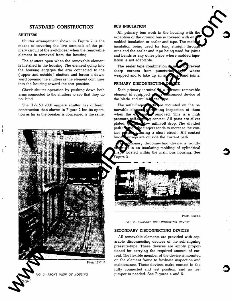
Shutter arrangement shown in Figure 2 is the means of covering the live terminals of the primary circuit of the switchgear when the removable element is removed from the housing.
The shutters open when the removable element is installed in the housing. The element going into the housing engages the arm connected to the (upper and outside) shutters and forces it downward opening the shutters as the element continues into the housing toward the test position.
Check shutter operation by pushing down both arms connected to the shutters to see that they do not bind.
The HV-150 2000 ampere shutter has different construction than shown in Figure 2 but its operation as far as the breaker is concerned is the same.
Photo 13551-R
FIG. 2-FRONT VIEW OF HOUSING
PageS
BUS INSULATION
All primary bus work in the housing with the exception of the ground bus is covered with either molded insulation or sealer and tape. The molded insulation being used for long straight through runs and the sealer and tape being used for joints and bends or any other place where molded insulation is not adaptable.
The sealer tape combination is used to prevent sharp corners from puncturing tape where wrapped and to take up air spaces around joints.
PRIMARY DISCONNECTING DEVICE
Each primary terminal of a drawout removable element is equipped with a disconnect device of the blade and multi-finger type.
The multi-finger parts are mounted on the removable element permitting inspection of them when the element is removed. This is a high pressure self-aligning contact. All parts are silver plated, giving a low millivolt drop. The divided path through the fingers tends to increase the contact pressure during a short circuit. All contact finger springs are outside the current path.
The stationary disconnecting device is rigidly mounted in an insulating molding of cylindrical shape located within the main bus housing. See Figure 3.
Photo 13562-R
FIG. 3-PRIMARY DISCONNECTING DEVICE
SECONDARY DISCONNECTING DEVICES
All removable elements are provided with separable disconnecting devices of the self-aligning pressure-type. These devices are amply proportioned for carrying the required amount of current. The flexible member of the device is mounted on the element frame to facilitate inspection and maintenance. These devices make contact in the fully connected and test position, and no test jumper is needed. See Figures 4 and 5.
www . El
ectric
alPar
tMan
uals
. com
www . El
ectric
alPar
tMan
uals
. com

'·
Photo 11938-R
FIG. 4-SECONDARY DISCONNECTING DEVICEBEFORE ENGAGEMENT
1 STATIONARY BASE ASSEMBLY 5 FLEXIBLE CONDUCTOR 2 SLIDE 6 HINGE 3 SHOE 7 NUT 4 CONTACT SPRING 8 MOVABLE BASE ASSEMBLY
Drawing S-11495
FIG. 5-SECONDARY DISCONNECTING DEVICE ENGAGED
GROUND BUS AND CONTACTS
The ground bus is located as shown in Figure 2 to left of guide and extends up from the floor 4 inches and toward the front approximately 18 inches. The ground bus contacts are located in the center of the bottom rear crosspiece of the removable element as shown in Figure 6 and engages ground bus before element reaches test position. These ground contacts have a rating of twenty-five percent the rating of the removable element of which it is a part.
Photo 13548-R
FIG. 6-REAR VIEW OF REMOVABLE ELEMENT
CONTROL BUS
All control buses are mounted in the rear of the metering compartment. All electrically operated equipment is connected to this control bus through a suitable control circuit protective device. See Figure 7.
Photo 13654-R
FIG. 7-CONTROL BUS MOUNTED IN REAR OF COMPARTMENT
Page 7 www . El
ectric
alPar
tMan
uals
. com
www . El
ectric
alPar
tMan
uals
. com
REMOVABLE ELEMENTS
GENERAL
Removable elements are crated and shipped separately and without parts of the element being blocked or wired for shipping protection. They are ready for operation and installation into housing when uncrated.
On each switchboard all removable elements of like rating are interchangeable unless the secondary (control) circuit require otherwise. In these cases interlocking will be used to prevent interchangeability.
Removable elements and housing are each set in a jig at the factory. All elements with each switchboard are tried at the factory in all housings on the board in which they could possibly be used. This makes certain of interchangeability. In cases of extensive damage in shipment, the repair should include checking those dimensions which affect interchangeability.
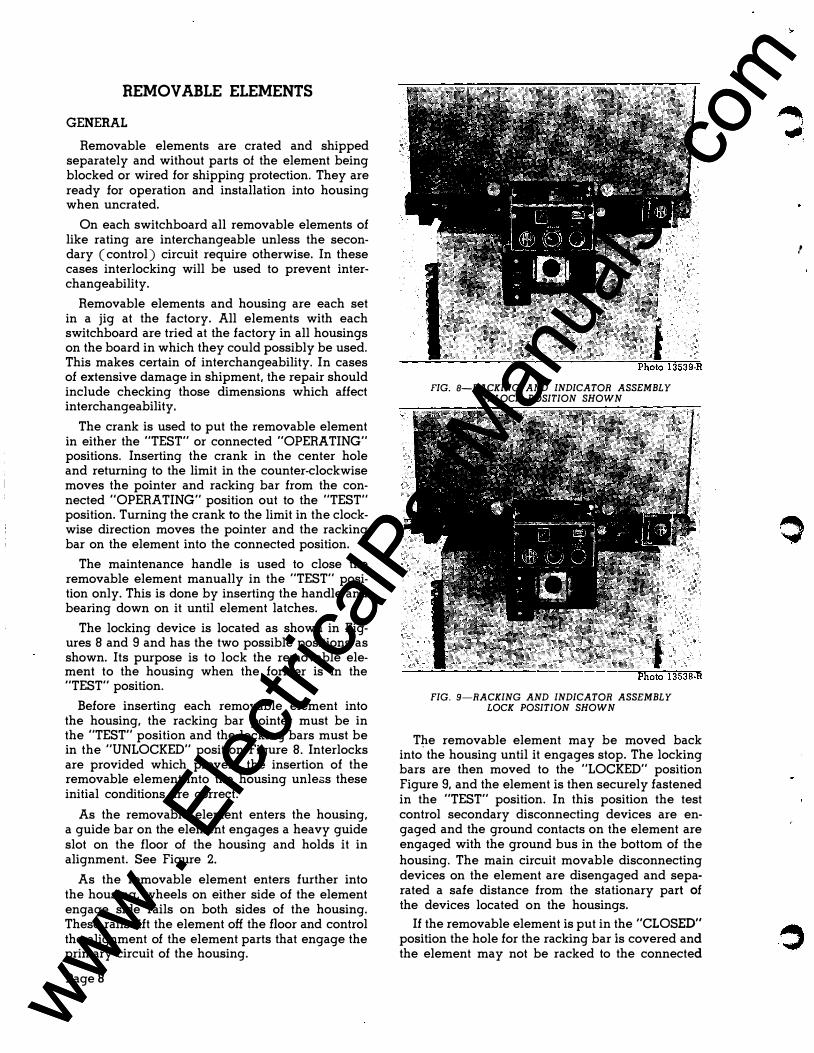
The crank is used to put the removable element in either the "TEST" or connected "OPERATING" positions. Inserting the crank in the center hole and returning to the limit in the counter-clockwise moves the pointer and racking bar from the connected "OPERATING" position out to the "TEST" position. Turning the crank to the limit in the clockwise direction moves the pointer and the racking bar on the element into the connected position.
The maintenance handle is used to close the removable element manually in the "TEST" position only. This is done by inserting the handle and bearing down on it until element latches.
The locking device is located as shown in Figures 8 and 9 and has the two possible positions as shown. Its purpose is to lock the removable element to the housing when the former is in the "TEST" position.
Before inserting each removable element into the housing, the racking bar pointer must be in the "TEST" position and the locking bars must be in the "UNLOCKED" position Figure 8. Interlocks are provided which prevent the insertion of the removable element into the housing unlezs these initial conditions are correct.
As the removable element enters the housing, a guide bar on the element engages a heavy guide slot on the floor of the housing and holds it in alignment. See Figure 2.
As the removable element enters further into the housing, wheels on either side of the element engage side rails on both sides of the housing. These rails lift the element off the floor and control the alignment of the element parts that engage the primary circuit of the housing.
PageS
FIG. 8-RACKING AND INDICATOR ASSEMBLY UNLOCK POSITION SHOWN
FIG. 9-RACKING AND INDICATOR ASSEMBLY LOCK POSITION SHOWN
T�e removable element may be moved back into the housing until it engages stop. The locking bars are then moved to the "LOCKED" position Figure 9, and the element is then securely fastened in the "TEST" position. In this position the test control secondary disconnecting devices are engaged and the ground contacts on the element are engaged with the ground bus in the bottom of the housing. The main circuit movable disconnecting devices on the element are disengaged and separated a safe distance from the stationary part of the devices located on the housings.
If the removable element is put in the "CLOSED" position the hole for the racking bar is covered and the element may not be racked to the connected
'
www . El
ectric
alPar
tMan
uals
. com
www . El
ectric
alPar
tMan
uals
. com
"OPERATING" position but if the element is in the "OPEN" position the racking handle may be inserted and the element be racked to the connected position.
At all positions of the removable element between the "TEST" and connected "OPERATING" positions, the latch of the element is held in the disengaged position, so that the element may not be closed either manually or electrically. The interlock that holds the latch in the disengaged position is mounted on the element and is operated by the racking bar.
With the removable element in the connected "OPERATING" position, it is usual to connect the control circuits so that the element can be operated from a control switch mounted on the front of the housing or from a remote point. The element cannot be operated from the push button station on its front panel, Figure 9. The push button station operates the element only in the "TEST" position. In this position the control switches are inoperative. Other connections are sometimes made at the request of the user.
An outlined procedure for installing and removing a removable element from service is as follows:
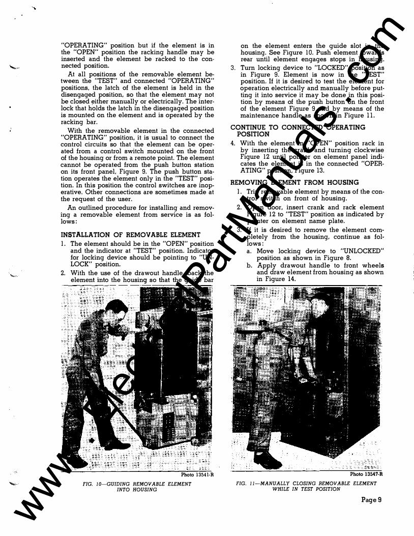
INSTALLATION OF REMOVABLE ELEMENT l . The element should be in the "OPEN" position
and the indicator at "TEST" position. Indicator for locking device should be pointing to "UNLOCK" position.
2. With the use of the drawout handle, back the element into the housing so that the guide bar
Photo 1354l·R
FIG. 1 0-GUIDING REMOVABLE ELEMENT INTO HOUSING
on the element enters the guide slot in the housing. See Figure 10. Push element towards rear until element engages stops in housing.
3. Turn locking device to "LOCKED" position as in Figure 9. Element is now in the "TEST" position. If it is desired to test the element for operation electrically and manually before putting it into service it may be done in this position by means of the push button on the front of the element Figure 9 and by means of the maintenance handle as shown in Figure 11.
CONTINUE TO CONNECTED OPERATING POSITION
4. With the element in "OPEN" position rack in by inserting the crank and turning clockwise Figure 12 until pointer on element panel indicates the element is in the connected "OPERATING" position, Figure 13.
REMOVING ELEMENT FROM HOUSING l . Trip removable element by means of the con
trol switch on front of housing. 2. Open door, insert crank and rack element
Figure 12 to "TEST" position as indicated by pointer on element name plate.
3. If it is desired to remove the element completely from the housing, continue as follows: a. Move locking device to "UNLOCKED"
position as shown in Figure 8. b. Apply drawout handle to front wheels
and draw element from housing as shown in Figure 14.
Photo 13547·R
FIG. 11-MANUALLY CLOSING REMOVABLE ELEMENT WHILE IN TEST POSITION
PageS www . El
ectric
alPar
tMan
uals
. com
www . El
ectric
alPar
tMan
uals
. com

FIG.12 Photo 13545-R
FIG.14 Photo 13543-R
Page 10
FIG. 13 Photo 13544-R
FIG. 12-RACKING IN REMOVABLE ELEMENT TO
FULLY CONNECTED POSITION
FIG. 13-REMOVABLE ELEMENT IN FULLY
CONNECTED POSITION
FIG. 14-PULLING OUT REMOVABLE ELEMENT
FROM HOUSING
www . El
ectric
alPar
tMan
uals
. com
www . El
ectric
alPar
tMan
uals
. com

HOW TO PUT THE SWITCHGEAR
IN SERVICE
GENERAL
Before energizing the switchgear observe that:
l . The board is completely assembled with all barriers in place, all joints taped and all extraneous material has been removed.
2. Potential tests have been made to determine that all insulation is in good condition.
3. All outgoing cables are either permanently connected or thoroughly insulated-so as not to cause a fault, especially at end remote from switchboard.
4. All short circuiting strips are removed from current transformers, and relays are not blocked.
5. All circuits are properly phased.
6. There is a backup removable element which is in operating condition and set so as to clear any fault that inadvertently may occur.
SAFETY PRECAUTIONS
THE REMOVABLE ELEMENTS SHOULD BE IN TEST POSITION WHEN PRACTICABLE. WHEN A THOROUGH INSPECTION OR WORK IS REQUIRED ON AN ELEMENT, IT MUST BE REMOVED FROM THE HOUSING. THE BUS . SHOULD BE DE-ENERGIZED AND GROUNDED WHENEVER POSSIBLE WHEN WORK IS TO BE DONE ON SWITCHGEAR.
PROCEDURE
First energize the control circuit with the main power circuit de-energized.
With the removable element in the test and connected position, open and close the element by push buttons on the element or from the control switch, or any remote operating point that may be provided. The element may be tripped by manually manipulating all relays and protective devices. Interlocks and special controls may be checked for proper operation.
The main power may now be applied to the switchgear' after all removable elements have been placed in the test position. Close all doors to the switchgear as a safety measure. Those elements necessary to energize the main bus should be moved to the connected position and closed. Observe undervoltage relays or other devices that should function properly when the main bus is energized. Next move each removable element in turn to the connected position and close. (Method explained under "INSTALLATION OF REMOVABLE ELEMENT.") Observe that all relays and instruments are functioning properly. Improper readings of watt meters, power factor meters, and watt hour meters usually indicate improper phasing of meter wiring.
When a switchgear installation is fed from one or more generators, it is usual to bring each generator up to speed and connect it to the bus so as to make adjustments on it for speed and voltage. The generators are then synchronized and adjusted for load division.
When a switchgear installation controls synchronous or induction motors, there may be special adjustments of relays and control devices that must be made for the proper operation of the motors.
BIBLIOGRAPHY
Description Reference
Specific Information for Type 5HV-50 Removable Elements Bulletin 491 04
Specific Information for Type 5HV-150 Removable Elements . . . . Bulletin 49105
Printed in U. S. A.
3-53-500
Page 1 1 www . El
ectric
alPar
tMan
uals
. com
www . El
ectric
alPar
tMan
uals
. com

.... ,
• I
www . El
ectric
alPar
tMan
uals
. com
www . El
ectric
alPar
tMan
uals
. com