Bulletin 1724E-214 - Coldrocks - utility...
57
Transcript of Bulletin 1724E-214 - Coldrocks - utility...


Bulletin 1724E-214 Page ii
BLANK PAGE

Bulletin 1724E-214 Page iii
TABLE OF CONTENTS
INSTRUCTIONS WHEN USING THE GUIDE SPECIFICATIONS FOR STANDARD CLASS STEEL TRANSMISSION POLES………………………………………..……………….v–viii TECHNICAL SPECIFICATIONS 1. Scope....................................................................................................................................... 1 2. Definitions .............................................................................................................................. 2 3. Codes and Standards ............................................................................................................... 2 4. Conflicts Between Specifications, Drawings, and Reference Documents ............................ 3 5. General Requirements............................................................................................................. 3 6. Shipping and Delivery ............................................................................................................13 7. Drawings and Information To Be Supplied By The Manufacturer ........................................13 8. Approvals, Acceptance and Ownership .................................................................................14 9. List of Attachments To This Specification .............................................................................14 Attachment A – Structure Dimensions and Pole Framing Drawings ......................................15 Attachment B - Application Requirements .............................................................................17 Attachment C – Standard Class Steel Pole Bid Summary.......................................................19 APPENDIX A – COMMENTARY APPENDIX B – EXAMPLES OF DRAWINGS APPENDIX C – DESIGN EXAMPLES APPENDIX D – SELECTED METRIC CONVERSIONS
ABBREVIATIONS
ACA Ammoniacal Copper Arsenate kV kilovolt ACSR Aluminum conductor steel reinforced mph miles per hour ACZA Ammoniacal Copper Zinc Arsenate LF Load factor ANCO American Nut Company NACE National Association of Corrosion
Engineers AISC American Institute of Steel
Construction NESC National Electrical Safety Code
ANSI American National Standards Institute NEMA National Electrical Manufacturers Association
ASCE American Society of Civil Engineers OHGW Overhead ground wire ASTM American Society for Testing and
Materials RUS Rural Utilities Service
AWS American Welding Society SSPC Steel Structure Painting Council CCA Chromated Copper Arsenate psf pounds per square foot DFT Dry Film Thickness psi pounds per square inch Eq. F Equivalency Factor UNC unified coarse threads HSS High Strength Steel ksi kips (1000 lb.) per square inch

Bulletin 1724E-214 Page iv
DEFINITIONS
Borrower - An entity which borrows or seeks to borrow money from, or arranges financing with the assistance of the Rural Utilities Service through guarantees, lien accommodations or lien subordinations. RUS Form 198 - Equipment Contract Rural Utilities Service (RUS) – An Agency of the United States Department of Agriculture. INDEX: MATERIALS AND EQUIPMENT: Guide Specifications for Standard Class Steel Poles POLES: Steel SPECIFICATIONS AND STANDARDS: Guide Specifications for Standard Class Steel Poles. TRANSMISSION FACILITIES: Poles (Steel)

Bulletin 1724E-214 Page v
INSTRUCTIONS WHEN USING THE GUIDE SPECIFICATIONS
FOR STANDARD CLASS STEEL TRANSMISSION POLES
A. Purpose: The intent of this guide specification is to provide Rural Utilities Service (RUS) Electric Program borrowers a basis for procuring standard class steel poles for transmission applications. Use of this specification should help eliminate ambiguities that might arise in the evaluation process of competitively bid standard class steel poles procurements. Borrowers or their engineering representatives will need to complete and add to this specification as appropriate. Modifications to this specification may be necessary to consider special applications or preferences of the owner. B. Scope: This suggested purchase specification covers the technical aspects of design, materials, manufacturing, inspection, testing, and delivery of direct embedded standard class steel poles. It is recommended that this specification be limited to single poles that are not guyed, not subjected to unbalanced lateral loads, or do not have unusual deflection or other special limitations. For applications that consider these items, it is recommended that the owner use “Guide Specifications for Steel Single Pole and H-Frame Structures,” RUS Bulletin 1724E-204. This guide specification does not include contract (front-end) documents or specifications for construction. The user of this specification should add these documents, including general conditions and any supplemental instructions to the bidders. This specification may be expanded to include H-frame structures. C. Initial Design Considerations: There are engineering decisions required of the user of this specification to determine which standard class steel poles to specify. Some examples include, but are not limited to: • Amount of foundation rotation in contributing to P-delta moments; • Location of point of fixity; • Embedment depths; • Load cases to be considered in addition to those required by the National Electrical Safety
Code (NESC); and • Deflection limitations.
Prior to the selection of a standard class pole, the user should perform the engineering required for these types of issues or employ an engineering consultant to do so. See Appendix A of this bulletin for a discussion of some of these items. D. Information to be completed by the owner – Users of these specifications should detach the instructions and the Appendices, and add or complete the following: D.1 Documents and general information to be added to the technical specification: Front-end documents and general information which need to be added to this technical specification.
a. RUS Form 198, Equipment Contract (Recommended for competitive bidding) b. Supplemental Instructions to Bidders c. General Conditions
When there is competitive bidding, it is recommended that RUS Form 198 be used. This form covers Notice and Instructions to Bidders, Proposal, and Equipment Contract. For item b above, Supplemental Information, the user may want to add such items as Bid Submission, Bid Price and Schedule, Bid Acceptance Period, Bid Requirements, and Bid Data. A section on

Bulletin 1724E-214 Page vi General Conditions could include such items as Definition of Terms, Interpretation of Bid Documents, Addenda to the Bid Documents, Insurance, Method of Payment (if RUS Form 198 is not used), Quantities, and Tabulation of Unit Prices. D.2 Requirements to the technical specifications to be added or completed by the owner or owner’s representative and supplied to the bidders include:
a. Configuration requirements and other information (Attachment A of the Specification or equivalent):
• Pole Length; • Pole Class; • Pole Framing (Pole attachment requirements);and • Embedment depths (Groundline location).
b. Strength requirements and Standard class designations for steel poles
This specification establishes standard steel poles sizes. The engineer in the design process needs to select the appropriate standard class pole from Table 1 based on loading requirements and a calculated load 2 feet from the top.
Minimum design loads have to meet NESC requirements which are appropriate for the loading district, the NESC extreme wind load provisions, NESC extreme ice with concurrent wind and any necessary extreme ice and wind conditions with the appropriate load factors and any local codes. The design loads account for all loading cases, including wind on pole and secondary stresses from foundation deflection and rotation, and from vertical loads acting on lateral pole deflection (P-delta effect).
The American Society of Civil Engineers (ASCE) Guidelines for Electrical Transmission Line Structural Loading can be used for developing loads produced by climate, accidents, construction and maintenance. Calculations need to include the vertical, transverse, and longitudinal loads with wind on the structure and the dead weight of the structure for any given loading condition applied simultaneously. All loads require appropriate load factors.
c. Application Requirements (Attachment B of the Specification to be completed by the owner.)
(1) Type of pole finish. (2) Special Charpy requirements. (3) Desired method of surface protection. (4) Preference of climbing ladders, steps or stepbolts. Also, quantity of
removable ladders, steps or step bolts to be supplied with the total order of poles should be specified.
(5) Location of climbing and /or working ladders or step bolts. (6) Ground collar (7) Pole grounding method. (8) Delivery schedule, and free on board destination, and owner’s contact. (9) Miscellaneous additional items such as special attachments requirements,
climbing devices, hot line maintenance requirements switch operating mechanisms, location of bolt holes for other equipment requirements.
(10) Pole tests (if required).

Bulletin 1724E-214 Page vii
E. Information to be completed by the Manufacturer
E.1 The owner or owner’s representative should have the following information completed and submitted by each bidder (Attachment C of this specification or equivalent).
a. Design information (Pole Framing Drawing and length). This will demonstrate conformance with the design needs.
b. For each standard class steel pole, provide the diameter at the top, at the ground line, and at the bottom, plus the pole taper. This will demonstrate conformance with the requirements of paragraph 5.1.2c.
c. For each standard class steel pole, provide the following general information: the weight of each pole; the tip load of each pole class; the location of the point of fixity; the type of steel according to American Society of Testing and Materials (ASTM) number and yield; the pole cross sectional shape; and the connection details for multiple piece poles (slip/flange joints). This will demonstrate conformance with the requirements of paragraphs 5.1.1, 5.1.2, 5.1.3, and 5.1.6.
d. For each standard class steel pole, provide the following calculations at the ground line: Moment, Shear, Axial load, and Cross sectional area. This will demonstrate conformance with the requirements of section 5.1.
e. For each standard class steel pole, provide the following calculations at the point of fixity: Moment, Shear, Axial load, and Cross sectional area. This will demonstrate conformance with the requirements of section 5.1.
f. For each standard class steel pole, provide the wall thickness at the pole top, ground line, and bottom. This may be provided in catalog form.
g. For each standard class steel pole provide the pole top deflection due to design load.
E.2 Documentation which the successful bidder needs to supply for approval by owner or owner's representative prior to manufacture of the pole include:
a. Description of pole including geometry, thickness, length, diameter, taper, and hole locations.
b. Complete design/erection reproducible drawings for each pole class.
c. Anticipated deflection of pole at specified tip load.
d. Connection and Assembly Details on multiple piece poles.
E.3 Test reports (as requested by the owner).

Bulletin 1724E-214 Page viii
BLANK PAGE
Bulletin 1724E-214 Page 1
SPECIFICATIONS FOR STANDARD CLASS STEEL TRANSMISSION POLES
1. SCOPE: This specification covers the design, materials, welding, inspection, protective coatings, drawings and delivery of unguyed standard class, direct embedded, steel transmission poles. The poles are to be used in single pole, unguyed situations. 2. DEFINITIONS: a. Appurtenance – Any hardware or structural members that are attached to the pole to make a
complete structure. b. Bearing Plate - A plate at the base of the pole that is intended to transfer the vertical loads of
the pole. c. Cambering – The fabrication of a slight convex curve in a pole. d. Charpy Impact - The impact properties of the material which are used to evaluate the
susceptibility of structural steel to brittle fracture. See ASTM A370 and ASCE Manual No. 72 for details.
e. Crook – A localized deviation from straightness that causes the centerline of one section of the
pole not to align with the centerline of another section of the pole. f. Circumferential Weld /C-weld - A weld perpendicular to the long axis of a structural member. g. D/t - The ratio of the diameter of a tubular pole to the plate thickness. h. Engineer – A registered or licensed person, who may be a staff employee or an outside
consultant, and who provides engineering services. Engineer also includes duly authorized assistants and representatives of the licensed person.
i. Ground Collar – An additional steel plate jacket that encapsulates the portion of the buried
pole immediately above and below the groundline
j. Group of Bolt Holes - All of the holes in which an appurtenance will be attached. k. Guyed Structure - A structure in which cable supports are used to increase its lateral load
resistance. l. Groundline – A designated location on the pole where the surface of the ground will be after
installation of a direct embedded pole. The groundline location will be used to locate the ground collar and other attachments to the pole.
m. Flanged Connection/splice – A bolted type connection. n. Factored Load - The design load that includes the appropriate load factor. o. In-Line Face – The face of the pole which “faces” an adjacent structure in the line. p. Longitudinal Weld - A weld parallel to the long axis of a structural member. q. Manufacturer – The company responsible for the fabrication of the poles. The manufacturer
fabricates the poles based on the design drawings developed by the structural designer, which is the manufacturer’s engineer responsible for the structural design of the poles.

Bulletin 1724E-214 Page 2 r. Load Factors (LF) – A multiplier, which is applied to each of the vertical, transverse and
longitudinal structure loads to obtain an ultimate load. s. Owner – The Rural Utilities Servic borrower or owner's representative. t. P-delta (P-∆) Moment – A measure of the increase in bending moment resulting from a
structure’s displacement under load. u. Pole Height - For this bulletin, this term is used interchangeably with pole length. v. Pole Length - The length from the pole top to the bearing plate on the pole bottom. w. Pole Sweep - The measure of deviation from straightness along the length of the pole. x. Point of Fixity – The point where the maximum moment occurs. The actual location of this
point is dependent on the characteristics of soils around the embedded portion of the pole. For this specification it will be assumed to be equal to 7 percent of the pole length.
y. Slip Connection/splice - A telescoping type connection of two tapered tubular pole sections. z. Standard Class Pole – A direct embedded steel pole that is designed according to a
standardized strength and loading criteria established by the owner. aa. Taper - The change in diameter of a tubular section from its base to its top. bb. Tip Load – The horizontal load that is applied to the standard class pole at a distance of 2 feet
from the pole top. cc. Ultimate Load – The maximum design load that includes the appropriate load factor specified. dd. Yield Strength – The minimum stress at which a material will start to physically deform
without further increase in the load or which produces a permanent 0.2 percent deformation. This is also known as the elastic limit of the material.
ee. Ultimate Moment Capacity - The moment that is developed in the pole at the time the yield
strength of the pole is realized. ff. w/t – Ratio of a flat width of a multisided pole to the thickness of the steel plate. gg. Weathering Steel - Steel that conforms to ASTM A588 or A871. This steel forms a natural
protective oxide layer on the surface. 3. CODES AND STANDARDS: Codes, standards, or other documents referred to in this specification shall be considered as part of this specification. The following codes and standards are referenced: a. American Institute of Steel Construction (AISC), “Specification for the Design, Fabrication
and Erection of Structural Steel for Buildings,” latest edition. b. American Society of Civil Engineers (ASCE) Standard, “Design of Steel Transmission Pole
Structures,” Manual 72, latest edition.

Bulletin 1724E-214 Page 3
c. American Society of Testing and Materials (ASTM), various standards, latest revision. Referenced ASTM specifications: A6/ A6M Specification for General Requirements for Rolled Structural Steel Bars,
Plates, Shapes, and Sheet Piling A36/A36M Specification for Carbon Structural Steel A123/A123M Specification for Zinc (Hot-Dip Galvanized) Coatings on Iron and Steel
Products A143 Practice for Safeguarding Against Embrittlement of Hot-Dip Galvanized
Structural Steel Products and Procedure for Detecting Embrittlement A153/153M Specification for Zinc Coating (Hot-Dip) on Iron and Steel Hardware A325 Specification for High-Strength Bolts for Structural Steel Joints A354 Specification for Quenched and Tempered Alloy Steel Bolts, Studs, and
Other Externally Threaded Fasteners A370 Test Methods and Definitions for Mechanical Testing of Steel Products A384 Practice for Safeguarding Against Warpage and Distortion During Hot-
Dip Galvanizing of Steel Assemblies A570/A570M Specification for Steel, Sheet and Strip, Carbon, Hot-Rolled, Structural
Quality A572/A572M Specification for High-Strength Low-Alloy Columbium-Vanadium
Structural Steel A588/588M Specification for High Strength Low-Alloy Structural Steel with 50 ksi
Minimum Yield Point to 4 in. Thick A595 Specification for Steel Tubes, Low-Carbon, Tapered for Structural Use A607 Specification for Steel, Sheet and Strip, High-Strength, Low-Alloy,
columbium or Vanadium, or Both, Hot-Rolled and Cold-Rolled A673/A673M Specification for Sampling Procedure for Impact Testing of Structural
Steel A687 Specification for High-Strength Nonheaded Steel Bolts and Studs A871/A871M Specification for High Strength Low-Alloy Structural Steel Plate with
Atmospheric Corrosion Resistance B695 Specification for Coatings of Zinc Mechanically Deposited on Iron and
Steel B696 Specification for Coatings of Cadmium Mechanically Deposited
d. American Welding society (AWS), Structural Welding Code, AWS D1.1, latest edition. e. American National Standards Institute (ANSI), National Electrical Safety Code, ANSI C2,
latest edition. f. Society for Protective Coatings (SSPC, formerly Steel Structure Painting Council)/ National
Association of Corrosion Engineers (NACE) Surface Preparations Specification, SSPC/NACE SP-6/NACE 3.
4. CONFLICT BETWEEN THIS SPECIFICATION, DRAWINGS, AND REFERENCES DOCUMENTS: In the event of conflict between this specification and the above referenced documents, the requirements of this specification shall take precedence. In the case of conflict between several referenced documents, the most stringent requirement shall be followed. If a conflict exits between this specification or the referenced documents and the attached drawings, the attached drawings shall be followed. If clarification is necessary, contact the owner. 5. GENERAL REQUIREMENTS: The design, fabrication, allowable stresses, processes, tolerances, and inspection shall conform to ASCE Standard, “Design of Steel Transmission Pole Structures” (Manual 72), latest edition, with the following additions and/or exceptions:
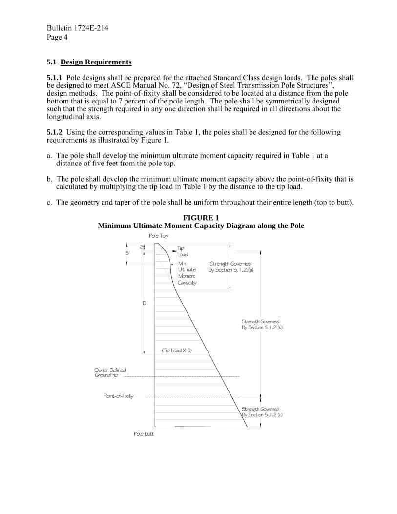
Bulletin 1724E-214 Page 4 5.1 Design Requirements 5.1.1 Pole designs shall be prepared for the attached Standard Class design loads. The poles shall be designed to meet ASCE Manual No. 72, “Design of Steel Transmission Pole Structures”, design methods. The point-of-fixity shall be considered to be located at a distance from the pole bottom that is equal to 7 percent of the pole length. The pole shall be symmetrically designed such that the strength required in any one direction shall be required in all directions about the longitudinal axis. 5.1.2 Using the corresponding values in Table 1, the poles shall be designed for the following requirements as illustrated by Figure 1. a. The pole shall develop the minimum ultimate moment capacity required in Table 1 at a
distance of five feet from the pole top. b. The pole shall develop the minimum ultimate moment capacity above the point-of-fixity that is
calculated by multiplying the tip load in Table 1 by the distance to the tip load. c. The geometry and taper of the pole shall be uniform throughout their entire length (top to butt).
FIGURE 1 Minimum Ultimate Moment Capacity Diagram along the Pole
(Tip Load X D)
Point-of-Fixity
Owner DefinedGroundline
Pole Butt
5'
D
Pole Top
2'LoadTip
By Section 5.1.2.(c)Strength Governed
Strength GovernedBy Section 5.1.2.(b)
Strength GovernedBy Section 5.1.2.(a)
Min. UltimateMoment Capacity

Bulletin 1724E-214 Page 5
5.1.3 The poles shall be designed to withstand the specified tip loading in Table 1 without exceeding a pole deflection of 15 percent of the pole length above the point of fixity when tested in accordance with ASCE Manual No. 72. 5.1.4 Overall length of poles shall be designed and manufactured in incremental lengths of 5 feet.
TABLE 1
Strength Requirements
Standard Class Designations for
Steel Poles
Minimum
Ultimate Moment Capacity At Five Feet
From Pole Top (Ft.–Kip)
Horizontal Tip Load
Applied 2 Ft from Pole Top
(Lbs.)
S-12.0 96 12,000 S-11.0 88 11,000 S-10.0 80 10,000 S-09.0 72 9,000 S-08.0 64 8,000 S-07.4 57 7,410 S-06.5 50 6,500 S-05.7 44 5,655 S-04.9 38 4,875 S-04.2 32 4,160 S-03.5 27 3,510 S-02.9 23 2,925 S-02.4 19 2,405 S-02.0 15 1,950
5.1.5 Poles shall be designed for the loads generated from handling and erecting without causing permanent deformation or damage to the pole when handled according to the manufacturer’s instructions. Handling and erecting loads shall include but not be limited to, a one-point (tilting) pickup and a two point (horizontal) pickup. 5.1.6 The maximum design unit stress shall be the minimum yield strength as stated in applicable ASTM specifications for the particular application and types of loads, including load factors. 5.1.7 Minimum plate thickness for all pole components shall be 3/16 inch. 5.1.8 The owner shall provide the pole manufacturer with the load capabilities, attachment method, and attachment location of the appurtenances. The pole manufacture shall verify that the pole will not have a localized strength problem at the attachment point. 5.1.9 All poles shall have bearing plates. Bearing plates shall have diameter not more than 2 inches greater than the maximum diameter at the pole butt. 5.1.10 Galvanized poles shall have a drain hole at the bottom. This hole shall not be greater than 20 percent of the bottom plate surface area. 5.1.11 Grade and type of steel shall be uniform for the poles.

Bulletin 1724E-214 Page 6 5.1.12 Ground collars to protect the pole groundline area from corrosive environments are required per Attachment B. Length of the ground collar shall be as specified in Attachment B. 5.1.13 Ground collars shall have a minimum thickness of 3/16 inch; shall be centered at the groundline; and shall not be considered in strength calculations. A seal weld shall be provided around the ground collar at the top and bottom of the ground collar. 5.1.14 The top of the pole shall be permanently covered with a structural steel plate that is bolted or otherwise permanently attached to the pole. The pole shall be delivered with the pole cover attached in place. 5.1.15 Lifting lugs are optional. The manufacturer shall supply all guidelines for handling and erection of poles and arms. 5.1.16 In the design of connections for vangs, brackets, or stiffeners attached to the pole shaft, care shall be taken to distribute the loads sufficiently to protect the wall of the pole from local buckling. 5.1.17 Weathering steel structures shall be designed to eliminate water and refuse traps. The tubular sections shall be sealed from moisture entering the inside of the pole. Factory drilled holes shall be plugged to prevent moisture intrusion during shipping. Connections shall be designed to reduce the effect of pack-out by preventing moisture from entering the joint or by designing the connection to allow moisture to easily drain off. 5.1.18 Plastic plugs shall be installed in all nuts welded to the structure and all tapped holes. 5.1.19 Pole design and design calculations shall be the responsibility of the manufacturer. 5.1.20 Poles shall be designed with the minimum number of joints. 5.1.21 Field welding is not normally permitted. In rare instances, it will be permitted to make minor repairs. All welds must be approved by the owner and must follow the manufacturer’s direction. 5.1.22 Flange connections for weathering steel poles shall be designed to avoid packout. 5.1.22 Application requirements: (See Attachment B of this Specification) 5.2 Materials 5.2.1 All materials shall comply with the applicable requirements of ASTM specifications. Any modifications from ASTM specifications must be approved by the owner or the owner’s representative. 5.2.2 Steel utilized for the purposes of making poles shall conform with the following ASTM Specifications: ASTM A36, ASTM A570, ASTM A572, ASTM 588, ASTM A607, ASTM A871 or ASTM A595, and must be qualified to the requirements contained in ASTM A6/A6M-96b. 5.2.3 Structural plate, and weld material, shall conform to ASTM A370 and ASCE Manual 72. Plates shall be heat-lot tested in conformance with ASTM A 673 Charpy V-Notch Impact test for properties of 15ft.lbs. at –20°F. 5.2.4 For galvanized structures, steel used for the pole shaft and arms shall have a silicon content less than .06 percent.
Bulletin 1724E-214 Page 7
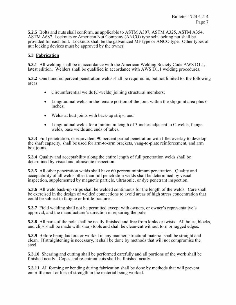
5.2.5 Bolts and nuts shall conform, as applicable to ASTM A307, ASTM A325, ASTM A354, ASTM A687. Locknuts or American Nut Company (ANCO) type self-locking nut shall be provided for each bolt. Locknuts shall be the galvanized MF type or ANCO type. Other types of nut locking devices must be approved by the owner. 5.3 Fabrication 5.3.1 All welding shall be in accordance with the American Welding Society Code AWS D1.1, latest edition. Welders shall be qualified in accordance with AWS D1.1 welding procedures. 5.3.2 One hundred percent penetration welds shall be required in, but not limited to, the following areas:
• Circumferential welds (C-welds) joining structural members; • Longitudinal welds in the female portion of the joint within the slip joint area plus 6
inches;
• Welds at butt joints with back-up strips; and
• Longitudinal welds for a minimum length of 3 inches adjacent to C-welds, flange welds, base welds and ends of tubes.
5.3.3 Full penetration, or equivalent 90 percent partial penetration with fillet overlay to develop the shaft capacity, shall be used for arm-to-arm brackets, vang-to-plate reinforcement, and arm box joints. 5.3.4 Quality and acceptability along the entire length of full penetration welds shall be determined by visual and ultrasonic inspection. 5.3.5 All other penetration welds shall have 60 percent minimum penetration. Quality and acceptability of all welds other than full penetration welds shall be determined by visual inspection, supplemented by magnetic particle, ultrasonic, or dye penetrant inspection. 5.3.6 All weld back-up strips shall be welded continuous for the length of the welds. Care shall be exercised in the design of welded connections to avoid areas of high stress concentration that could be subject to fatigue or brittle fractures. 5.3.7 Field welding shall not be permitted except with owners, or owner’s representative’s approval, and the manufacturer’s direction in repairing the pole. 5.3.8 All parts of the pole shall be neatly finished and free from kinks or twists. All holes, blocks, and clips shall be made with sharp tools and shall be clean-cut without torn or ragged edges. 5.3.9 Before being laid out or worked in any manner, structural material shall be straight and clean. If straightening is necessary, it shall be done by methods that will not compromise the steel. 5.3.10 Shearing and cutting shall be performed carefully and all portions of the work shall be finished neatly. Copes and re-entrant cuts shall be finished neatly. 5.3.11 All forming or bending during fabrication shall be done by methods that will prevent embrittlement or loss of strength in the material being worked.

Bulletin 1724E-214 Page 8 5.3.12 Holes for connection bolts shall be 1/8 inch larger than the nominal diameter of the bolts. Holes in the flange plates for bolted splices shall be 1/8 inch larger than the bolt diameter. The details of all connections and splices shall be subject to the approval of the owner or the owner’s representative. 5.3.13 Holes in steel plates which are punched must be smooth and cylindrical without excessive tear out or depressions. Any burrs that remain after punching shall be removed by grinding, reaming, etc. 5.3.14 Holes of any diameter may be drilled in plate of any thickness. Care shall be taken to maintain accuracy when drilling stacks of plates. 5.3.15 Holes may be made by use of a machine guided oxygen torch. Flame cut edges shall be reasonably smooth to minimize stress concentrations. 5.3.16 Field drilled holes must be approved by the owner. If the manufacturer is aware of the owner's intent to field drill holes, the manufacture must supply a galvanizing touch-up kit for galvanized poles or a silicon sealant for weathering steel poles. 5.4 Tolerances Manufacturing tolerances shall be limited to the following:
Pole Length
One piece: ±2 inches, or ±1 inch ±1/8 inch per 10 feet of length, whichever is greater (i.e. - 120 foot pole shall have a length of 120 feet ±2½ inches)
Assembled pole with flange connections: same as for one piece Assembled pole with slip joint connections: The accumulation of the slip joint tolerances not to exceed –6 inch, +12 inch
Pole Diameter
-0 inch, +1/4 inch
Pole End Squareness
±1/2 inch per foot of pole diameter
Pole Sweep
1/8 inch per 10 feet of pole length
Pole Twist
None Acceptable
Slip Joint tolerances
Tolerances per manufacturer’s recommendations and total pole length requirements above. See Paragraph 5.7
Pole Taper
See paragraph 5.1.2c .
Bulletin 1724E-214 Page 9
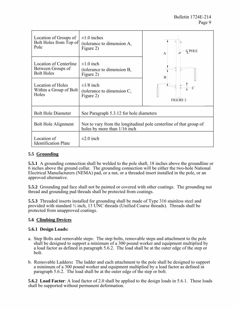
Location of Groups of Bolt Holes from Top of Pole
±1.0 inches (tolerance to dimension A, Figure 2)
Location of Centerline Between Groups of Bolt Holes
±1.0 inch (tolerance to dimension B, Figure 2)
Location of Holes Within a Group of Bolt Holes
±1/8 inch (tolerance to dimension C, Figure 2)
Bolt Hole Diameter
See Paragraph 5.3.12 for hole diameters
Bolt Hole Alignment
Not to vary from the longitudinal pole centerline of that group of holes by more than 1/16 inch
Location of Identification Plate
±2.0 inch
5.5 Grounding 5.5.1 A grounding connection shall be welded to the pole shaft, 18 inches above the groundline or 6 inches above the ground collar. The grounding connection will be either the two-hole National Electrical Manufacturers (NEMA) pad, or a nut, or a threaded insert installed in the pole, or an approved alternative. 5.5.2 Grounding pad face shall not be painted or covered with other coatings. The grounding nut thread and grounding pad threads shall be protected from coatings. 5.5.3 Threaded inserts installed for grounding shall be made of Type 316 stainless steel and provided with standard ½ inch, 13 UNC threads (Unified Coarse threads). Threads shall be protected from unapproved coatings. 5.6 Climbing Devices 5.6.1 Design Loads: a. Step Bolts and removable steps: The step bolts, removable steps and attachment to the pole
shall be designed to support a minimum of a 300 pound worker and equipment multiplied by a load factor as defined in paragraph 5.6.2. The load shall be at the outer edge of the step or bolt.
b. Removable Ladders: The ladder and each attachment to the pole shall be designed to support
a minimum of a 300 pound worker and equipment multiplied by a load factor as defined in paragraph 5.6.2. The load shall be at the outer edge of the step or bolt.
5.6.2 Load Factor: A load factor of 2.0 shall be applied to the design loads in 5.6.1. These loads shall be supported without permanent deformation.
FIGURE 2
A
B
C
C POLEL

Bulletin 1724E-214 Page 10 5.6.3 Location: Climbing devices shall start 8 feet above groundline and extend to the pole top unless specified by the owner. The climbing device shall be spaced such that each step is 1 foot 6 inches apart and orientated to provide maximum ease of climbing. They shall be located to avoid interference with other attachments. 5.6.4 Finish: Step bolts, removable steps, and removable ladders shall be hot dipped galvanized. For weathering steel poles, step bolts may be weathering steel. 5.6.5 Intent of steps/ladder: This system is intended for climbing the pole and working on the structure. It is not intended to replace the worker's fall arrest system. 5.7 Splices 5.7.1 Poles shall be designed with a minimum number of joints. Field welding shall not be allowed as part of the design of a new pole. The shaft joints to be made in the field shall be slip joints or bolted flange joints. Slip joints shall be designed for a nominal lap that will develop the full required design strength of the pole at that point. The minimum lap shall meet the requirements of ASCE Manual No. 72. All welds on both sections of the pole, in the area of the splice, shall be complete penetration welds for at least a length equal to the maximum lap dimension. 5.7.2 Manufacturer shall verify slip joint fit, through dimensional measurement or actual fit-up, before shipment. Joints should not interfere with threaded inserts, step nuts, ladder clips, or jacking nuts. 5.7.3 Sufficient jacking lugs and permanent orientation marks shall be provided at all slips joints to ensure proper alignment and complete overlap of the joint. 5.7.4 The axis of the pole shall not be distorted after the pole is mated. Shims shall not be allowed to straighten the pole unless approved by the owner. The owner reserves the right to reject a pole based on the improper mating of a pole splice. 5.8 Appurtenances 5.8.1 Appurtenance material shall be supplied by the owner. The owner shall provide the pole manufacturer connector and/or member locations, orientations, size, types, and strength capacities. 5.8.2 The steel pole manufacturer and the owner shall work together to assure design coordination and fit up of all appurtenance connections and members to poles. Also refer to paragraph 5.1.8 of this specification. 5.9 Finishes 5.9.1 The following finishes are acceptable: Galvanizing, zinc primer combined with paint, weathering steel, and a below grade coating. a. Galvanizing – All poles and structural components which are hot-dip galvanized shall meet all
the requirements of ASTM A123 or ASTM A153. Measures shall be taken to prevent warping and distortion according to ASTM A384 and to prevent embrittlement according to ASTM A143. Poles made of ASTM A588 steel shall not be galvanized due to the high silicon content of the steel. One gallon of zinc enriched paint shall be provided with each five poles.
b. Zinc Primer and Painting - Poles which are to be painted shall be hermetically sealed to
prevent corrosion of interior surfaces. After shot or sand blasting and cleaning in accordance with the surface preparations specification, SSPC/NACE SP-6/NACE 3, a zinc primer of 3 mils dry film thickness (DFT) and two coats of finish paint, each 3 mils DFT shall be applied

Bulletin 1724E-214 Page 11
to all exterior surfaces in accordance with the paint supplier's recommendations. One gallon each of primer and finish paint shall be supplied with each five poles. A guarantee against flaking or fading of the paint for a minimum of 5 years shall be provided.
c. Weathering Steel - Steel shall conform to ASTM A588 or A871. After fabrication, poles
made of weathering steel shall be cleaned of oil, scale, etc., in accordance with the surface preparation specification SSPC/NACE SP-6/NACE 3, to ensure uniform and rapid formation of the protective oxide layer.
d. Coatings for the Embedded Portion of the Pole A minimum 16 mil DFT of two component
hydrocarbon extended polyurethane coating that is resistant to ultraviolet light shall be applied on the exposed surface of the embedded portion of the pole. The coating shall extend from the butt to 2 inches below the top of the ground collar, or 16 inches above groundline. Other coatings shall be approved by the owner prior to their use. One-quart container of touch up shall be provided with each five poles.
5.9.2 Bolts and nuts with yield strengths under 100,000 psi shall be hot-dip galvanized per ASTM A153 and ASTM A143, or mechanically coated with zinc in accordance with ASTM B695, Class 50. Bolting materials with yield strengths in excess of 100,000 psi shall not be hot-dip galvanized. Instead, they shall be painted with zinc enriched paint or mechanically coated with zinc per ASTM B695, Class 50. Bolts and nuts made from weathering steel do not require a galvanizing coating. 5.9.3 Compliance with coating thickness requirements shall be checked with a magnetic thickness gauge. 5.10 Markings 5.10.1 Each Pole shall be permanently marked on the pole shaft 60 inches above groundline and on the bottom side of the bearing plate with the following identifying information, unless specified otherwise by the owner:
• Manufacturer’s name • Month and year of manufacture • Length and class of pole • Ultimate moment capacity of the pole • Owner’s name • Pole weight
5.10.2 The identification information listed above shall be permanently marked on the transverse side of the pole. The method of identification shall be approved by the owner. The lettering shall be at least 3/4 inch in height. 5.10.3 Information on the butt of the pole may be with permanent paint applied with a 1/2 inch wide brush. Paint identification markings may not be used in any other location. 5.10.4 Each section of a spliced pole shall be marked such that the intended mate section can be easily identified. The markings shall be permanent and legible and contain at least the following information:
• Pole Length and Class (each section and total pole); and • Structure number (if known).

Bulletin 1724E-214 Page 12 5.11 Inspection And Testing 5.11.1 The owner and the owner’s representative shall have free entry at all times during fabrication, to all parts of the manufacturer’s plant to inspect any part of the production of the poles covered by this specification. 5.11.2 Steel members that are bent or warped or otherwise improperly fabricated shall be properly repaired or replaced at the sole discretion of the owner. 5.11.3 The cost of tests made by the manufacturer (except full scale load tests on poles), including cost of the certified test reports shall be considered included in the bid price. 5.11.4 The manufacturer shall make tests in accordance with ASTM A370 and A673 to verify that the material used in the structures meets the impact properties. 5.11.5 Mill test reports showing chemical and physical properties of all material furnished under this specification shall be maintained by the manufacturer for a period of 5 years and shall be traceable to the pole. 5.11.6 All plates over 1-1/2 inches thick shall be ultrasonically tested to assure against defects that could lead to lamellar tearing. 5.11.7 Qualification of welders or welding operators will be verified as to conformance with the provisions of AWS D1.1. 5.11.8 The manufacturer shall make certified welding reports for each pole. The reports covering welding shall include all welds of a pole. Each weld shall be clearly identified; and the report shall consist of the method of testing, whether the weld is acceptable, the identification of the pole, the date, and the name and signature of the inspector. 5.12 Full Scale Structure Testing 5.12.1 The poles that are to have full-scale load tests performed on them are listed in Attachment B. Cost for such test shall be the responsibility of the owner, shall be separated from the manufacturer’s bid, and shall be negotiated in advance of any test preparation. 5.12.2 Details of the test procedures and methods of measuring and recording test loads and deflections shall be specified by the manufacturer prior to testing and shall be subject to the review and approval of the owner or the owner’s representative. 5.12.3 Deflections shall be recorded in the transverse and longitudinal directions when applicable. Deflection measurements shall be taken under the no load condition both before and after testing. 5.12.4 Material procurement for test poles shall be identical to material procurement procedures for regular production run poles. 5.12.5 A full report listing results shall be submitted after completion of all testing. Copies of mill test reports shall be included in the load test report. The report shall also include a compete description of the load tests with diagrams and photographs. 5.12.6 The owner or the owner’s representative reserves the right to be present during testing and shall be notified 2 weeks prior to the start of pole test.

Bulletin 1724E-214 Page 13
6. SHIPPING AND DELIVERY 6.1 Shipping 6.1.1 Each shipment shall be accompanied by a bill of materials, identifiable by pole type and number. Bolts and miscellaneous hardware will be identified by the list for match up with the respective pole shaft. All parts that are required for any one pole shall be in one shipment, if possible. 6.1.2 The owner and owner’s representative shall be notified prior to shipment that such shipment is to take place, and they reserve the right to inspect the components prior to shipment. The notification shall give quantities, weight, name of common carrier used, and expected time of arrival. 6.1.3 Salt-treated wood blocking and urethane foams shall not be used when shipping or storing weathering steel poles. 6.1.4 Transportation and site handling shall be performed with acceptable equipment and methods by qualified personnel. The manufacturer shall exercise precaution to protect poles against damage in transit. 6.1.5 Handling instructions shall be included with the pole shipment (if special handling is required). 6.2 Delivery 6.2.1 The owner may take delivery at a designated location with the delivering carrier’s equipment. The manufacturer shall coordinate with the owner to ensure smooth and efficient delivery of poles. 6.2.2 The owner will provide all labor, equipment, and materials for the unloading of poles at the project site. A pole is considered delivered when the pole is lifted from the trailer or semitrailer of the delivery carrier. 7. DRAWINGS AND INFORMATION TO BE SUPPLIED BY THE MANUFACTURER 7.1 Information to be Supplied with the Proposal (See Attachment C) a. Pole diameter at the top, groundline, and bottom. b. The pole taper of each pole in inches/foot. c. The calculated weight of each class and length of pole. d. General information about each pole length and class including tip load, location of point of
fixity, type of steel used for the pole (ASTM number and yield), cross sectional shape, and connection details of multiple piece poles (slip joints/flange joints/welded to be one piece).
e. Calculated groundline and point-of-fixity reactions due to the tip loadings (including shear, moment, and axial reactions) in order to demonstrate conformance with the requirements of 5.1.1 and 5.1.2.
f. Description of pole shaft cross section including thickness of the plate at the bottom, groundline, and at the top.
g. For each standard class pole, provide pole top deflection using the specified tip loading in order to demonstrate conformance with the requirements of and 5.1.3.
h. The cost of each pole by size and length. Also the total order cost for each class and length of pole.

Bulletin 1724E-214 Page 14 7.2 Documentation to be Supplied for the Owner’s Approval Prior to Fabrication (as requested by the owner): Documentation includes final design calculations for the pole shaft at 5-foot intervals and will be based upon the pole loading shown in Table 1. The following information shall be supplied:
• Total shear forces • Moment • Design Stress, Allowable stress, and Stress ratio • Section moduli • Cross-sectional area • Deflection at the pole top due to tip load • Detail drawings for each structure type giving weights of structure • Bill of materials list (if any) • Assembly instructions and erection drawings
(Slip joint lengths and allowable tolerances) • Special handling instructions (if required)
7.3 Test Reports (as requested).
• Certified mill test reports for all structural material. • Certified welding reports for each pole. • Impact property test reports showing that the material used in the poles meets the impact
properties. • Test reports on coating thickness. • Report of pole testing, when required, including photographs, and diagrams.
8. APPROVALS, ACCEPTANCE AND OWNERSHIP 8.1 Final designs must be approved by the owner or owner’s representative before material ordering and fabrication. Material ordering and fabrication prior to approval will be at supplier’s risk. It is understood that award of this contract does not constitute acceptance of design calculations submitted with the bid, if corrections are required in the final structure designs due to manufacturer’s errors, omissions, or misinterpretations of the specifications, the quoted price shall not change. Approval of the drawings and calculations by the owner or the owner’s Representative does not relieve the supplier of responsibility for the adequacy of the design, correctness of dimensions, details on the drawings, and the proper fit of parts. 8.2 After delivery, the poles will be inspected and shall be free of dirt, oil blisters, flux, black spots, dross, teardrop edges, flaking paint or zinc; and in general shall be smooth, attractive, and unscarred. Poles not meeting this requirement shall be repaired or replaced by the manufacturer at no additional cost to the owner. Final decision to repair rather than replace a pole shall be at the owner’s sole discretion. 8.3 All final drawings shall become the property of the owner, who shall have full rights to reproduce drawings and use them as the owner sees fit. 9. LIST OF ATTACHMENTS TO THIS SPECIFICATION: (Attachment A, and B to be completed by the engineer. Attachment C to be completed by the manufacturer)
• Attachment A, Structure Dimensions and Pole Framing Drawings • Attachment B, Application Requirements • Attachment C, Bid Summary

Bulletin 1724E-214 Page 15
Attachment A
Structure dimensions and pole framing drawings

Bulletin 1724E-214 Page 16
BLANK PAGE

Bulletin 1724E-214 Page 17
Attachment B
Application Requirements
1. Type of finish of the pole (indicate by checking one) Weathering____________________________ Galvanized____________________________ Zinc primer and paint____________________
2. Special Charpy requirements __________________________
3. Surface protection desired for embedded portion of the pole (indicate by checking one
or both) Polyurethane Coating____________________
Anodes_______________________________ 4. Climbing device type (indicate by checking one)
Step Bolts_____________________________ Ladder ______________________ Removable Steps_______________________
5. Location of climbing device ____________________________
6. Length of ground collar ____________________________
7. Grounding plate or nut ___________________________
8. Delivery schedule _____________________
9. Free on board destination ____________________________
10. Pole test (if required) ______________________________
11. Additional Requirements (below) ____________________________
Bulletin 1724E-214 Page 18
BLANK PAGE

Bulletin 1724E-214 Page 19
Attachment C
Standard Class Steel Pole Bid Summary (Information to be supplied with the bid)
DESIGN INFORMATION Pole framing drawing Pole Class Pole Length POLE DESCRIPTION Top Diameter Groundline Diameter Bottom Diameter Taper (in/ft) GENERAL Pole Wt/ each Tip Load Point of Fixity Loc Steel (ASTM/yield ) Cross section shape Splice joint type CALCULATIONS AT THE GROUNDLINE Moment Shear Axial Cross Sectional Area CALCULATIONS AT THE POINT OF FIXITY Moment Shear Axial Cross Sectional Area WALL THICKNESS Top Groundline Bottom DEFLECTION (Top)
COST SUMMARY COST/POLE NUMBER OF POLES TOTAL COSTS
TRANSMISSION LINE POLES ATTACHMENT C
BID SUMMARY – DESIGN INFORMATION,WEIGHTS, AND PRICE INFORMATION
COMMENTS:
(INFORMATION TO BE SUPPLIED
WITH THE PROPOSAL)

Bulletin 1724E-214 Page 20
BLANK PAGE

Bulletin 1724E-214 Appendix A
Page 1
APPENDIX A COMMENTARY
A. General The necessity of a clear bid specification for the purchase of standard class steel poles is very important to the bid evaluation process and the acquisition of structurally adequate poles. The specification should contain sufficient requirements and information so that all bids can be evaluated equally and so that the manufacturer clearly understands what is expected of the manufacturer. Scope While use of this standard class steel pole specification is not prohibited to poles which are guyed, which are subjected to unbalanced lateral loads or which have deflection or other special limitations, the owner must be prudent when using this specification in these types of applications. It is recognized that, with the proper understanding and usage of some computerized structural analysis and transmission line design programs, it is possible to select a standard class steel pole which might otherwise be beyond the scope of this specification. The owner must be sure that combined bending and buckling analysis is performed, and that deflections are properly modeled. The owner should recognize when the design of a steel pole may be more prudently accomplished using the “Guide Specification for Steel Single Pole and H-Frame Structures,” RUS Bulletin 1724E-204, which requires the actual loading conditions to be specified. In using RUS Bulletin 1724E-204, the manufacturer assumes full responsibility in designing and manufacturing a structurally adequate pole. Standard Class Pole In some cases, utilities prefer to specify certain steel poles to be designed according to standardized loading criteria, much like the standard classifications for wood poles. In utilizing standard class steel poles, a complete structural analysis is still required for all structures. All appropriate loading criteria are considered in the analysis. Once the required steel pole strength is determined, a standard class steel pole that meets the actual loading conditions can be selected. A complete design example is shown in Appendix C. Without considering all the potential reasons for specifying standard class poles, this specification is developed in order to establish a standard classification system and to assist the owner in procuring a standard class steel pole which is properly designed for the intended loading criteria. This guide specification attempts to eliminate ambiguity in specifying and purchasing standard class steel poles. Since it has become a widespread practice in the industry to design and manufacture poles which are based on the wood pole classification system of the American National Standards Institute (ANSI 05.1), the steel pole classifications developed in this specification generally follow the wood pole classification system. However, to avoid confusion with the wood pole classifications, the steel pole classifications have a unique naming system. Wood Pole Equivalency In some cases, the owner may design a transmission line based on wood pole classifications as described in ANSI 05.1 and then wish to order steel poles which meet the wood pole equivalent
Bulletin 1724E-214 Appendix A Page 2 loadings. Because of the differences in strength factors applied to wood poles in comparison to steel poles, the owner must be sure that the strength factors are properly accounted for in the design of the steel poles. “Wood pole equivalent” is a term that may be defined in a number of ways. For purposes of this commentary, the term “wood pole equivalent” is defined as a standard class steel pole which is equated by required ultimate loading to an ANSI 05.1 standard class wood pole. The equation is made by a ratio of the strength factors applicable for each pole type and loading criteria. The design and purchase of steel poles as an equivalent to wood poles can be vague even with clear instructions. As such, the owner should be sure that the equivalency is properly determined. Once the equivalency is determined, the owner should specify the standard class steel pole based on the classifications detailed in paragraph 5.1.2. In doing this, the manufacturer will not be involved in the equivalency process and the ambiguity should be eliminated. The wood pole equivalency is based on the required ultimate moment capacity of the pole at the groundline based on embedment depths shown in ANSI 05.1. In obtaining a suitable equivalency, the owner must consider factors other than the equivalent groundline moment. For example, the differences in material and section properties of the wood pole versus the steel pole will result in differences in buckling analysis, pole deflections, secondary moments, applied wind forces, etc. It is impossible to completely equate the steel pole and wood pole at all points along the pole. The owner must be certain that the steel pole selected by equivalency methods will have strength sufficient for the actual application. Equivalency Factor (Eq.F) The equivalency factor (Eq.F) is defined as the ratio of the wood pole strength factor to the steel pole strength factor for a given loading condition. For example, for NESC Grade B district loading, the wood pole strength factor is 0.65 and the steel pole strength factor is 1.00. Thus, the equivalency factor will be 0.65/1.00 = 0.650. The equivalency factor is a useful concept to understand as the owner requires a wood pole equivalent under various loading conditions and strength factors. Several examples of equivalencies are listed in the following sections. Wood Pole Equivalency – 0.65 TO 1.00 Ratio (0.65 Eq.F) For the NESC Grade B district loadings, the NESC allows for a strength factor of 1.00 to be applied to a load on a steel pole while it requires a strength factor of 0.65 to be applied to a load on a wood pole. As such, the ultimate strength requirement for the steel pole will be less than the ultimate strength of the wood pole for the district loading conditions. For example, the owner designs a transmission line for wood poles based on NESC district wind loading conditions. The owner wishes to purchase a steel pole that is equivalent to a Class 1 wood pole. Based on ANSI 05.1, the Class 1 wood pole groundline strength is derived by applying a horizontal ultimate load of 4,500 pounds at 2 feet from the pole top based on a simple cantilever. Since the owner had classed the wood pole based on an NESC strength factor of 0.65, the owner wishes to select a steel pole meeting the same NESC district wind loading conditions. To do this, the owner will multiply the required tip loading of 4,500 pounds by 0.65/1.00, which equals 2,925 pounds. The 0.65/1.00 ratio (or 0.65 Eq.F) adjusts for the difference between wood and steel strength factors. The owner will then select a standard class steel pole which has an ultimate

Bulletin 1724E-214 Appendix A
Page 3
moment capacity based on the horizontal tip loading of at least 2,925 pounds. From paragraph 5.1.2, the owner selects a class S-02.9 pole, which has a tip loading of 2,925 pounds. Based on the method shown in this example, Table A-1 of this Appendix at the end of this section is a tabulation of wood pole equivalencies based on the NESC Grade B district loading. Wood Pole Equivalency - 0.75 TO 1.00 Ratio (0.75 Eq.F) For the NESC Grade B extreme wind loadings, this specification requires a strength factor of 1.00 to be applied to an extreme wind load on a steel pole while the NESC requires a strength factor of 0.75 to be applied to an extreme wind load on a wood pole. As such, the ultimate strength requirement for the steel pole will be less than the ultimate strength of the wood pole for the NESC extreme wind loading conditions. For example, the owner designs a transmission line for wood poles based on NESC extreme wind loading conditions. The owner wishes to purchase a steel pole that is equivalent to a Class 1 wood pole. Based on ANSI 05.1, the Class 1 wood pole groundline strength is derived by applying a horizontal ultimate load of 4,500 pounds at 2 feet from the pole top based on a simple cantilever. Since the owner had classed the wood pole based on an NESC extreme wind strength factor of 0.75, the owner wishes to select a steel pole meeting the same extreme wind loading conditions. To do this, the owner will multiply the required tip loading of 4,500 pounds by 0.75/1.00, which equals 3,375 pounds. The 0.75/1.00 ratio (or 0.75 Eq.F) adjusts for the difference between wood and steel extreme wind strength factors. The owner will then select a standard class steel pole which has an ultimate moment capacity based on the horizontal tip loading of at least 3,375 pounds. From paragraph 5.1.2, the owner selects a class S-03.5 pole, which has a tip loading of 3,510 pounds. Based on the method shown in this example, Table A-2 at the end of this section is a tabulation of wood pole equivalencies based on the NESC Grade B extreme wind loading. Wood Pole Equivalency – 1 TO 1 Ratio (1.0 Eq.F) The owner may wish to order a steel pole that has the same ultimate strength as a specified wood pole class. One common application of this is when the owner designs a transmission line using wood pole properties, but utilizing steel pole strength factors. In this case, the owner has accounted for the difference in wood versus steel strength factors during the design of the project. For example, the owner designs a transmission line for wood poles based on NESC district wind loading conditions. However for steel poles, the owner uses the NESC district strength factor of 1.00 (applicable to steel poles) in the calculations. The owner selects a wood pole Class 1 at a specific location. Thus, the owner wishes to purchase a steel pole which is equivalent in ultimate strength to a Class 1 wood pole. Based on ANSI 05.1, the Class 1 wood pole groundline strength is derived by applying a horizontal ultimate load of 4,500 pounds at 2 feet from the pole top based on a simple cantilever. Therefore, the owner will require a steel pole with an ultimate moment capacity based on the same 4,500 pound tip loading. From paragraph 5.1.2, the owner selects a Class S-04.9 steel pole, which has a tip loading of 4,875 pounds. Based on the method shown in this example, Table A-3 is a tabulation of wood pole equivalencies based on the ultimate-to-ultimate strength comparison, or 1.0 equivalency factor.
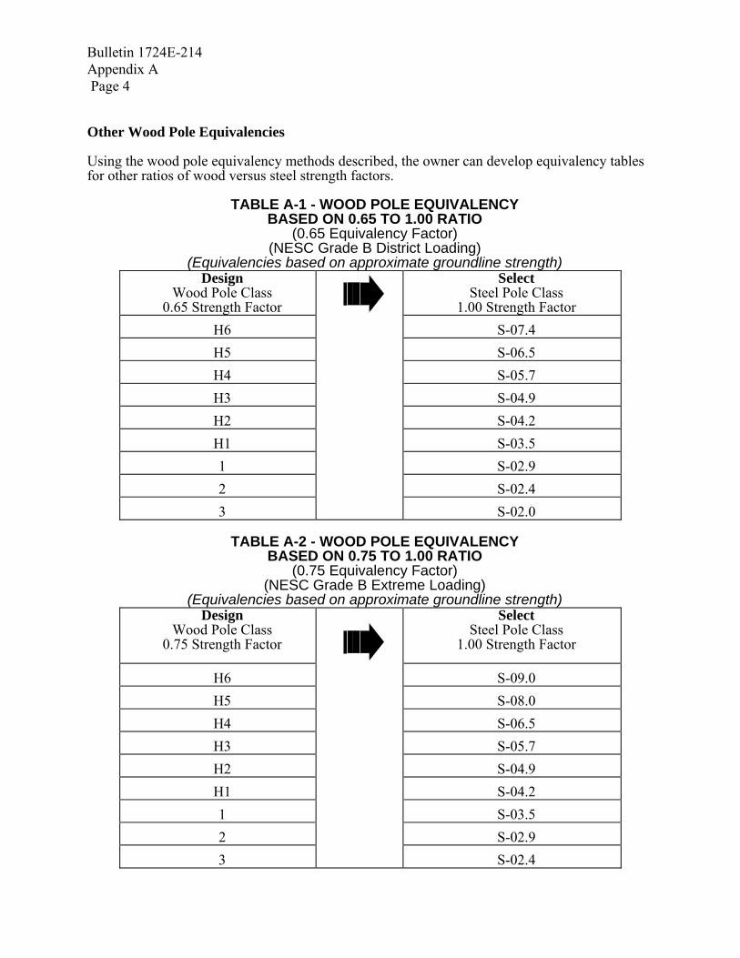
Bulletin 1724E-214 Appendix A Page 4 Other Wood Pole Equivalencies Using the wood pole equivalency methods described, the owner can develop equivalency tables for other ratios of wood versus steel strength factors.
TABLE A-1 - WOOD POLE EQUIVALENCY BASED ON 0.65 TO 1.00 RATIO
(0.65 Equivalency Factor) (NESC Grade B District Loading)
(Equivalencies based on approximate groundline strength) Design
Wood Pole Class 0.65 Strength Factor
Select Steel Pole Class
1.00 Strength Factor H6 S-07.4 H5 S-06.5 H4 S-05.7 H3 S-04.9 H2 S-04.2 H1 S-03.5 1 S-02.9 2 S-02.4 3 S-02.0
TABLE A-2 - WOOD POLE EQUIVALENCY
BASED ON 0.75 TO 1.00 RATIO (0.75 Equivalency Factor)
(NESC Grade B Extreme Loading) (Equivalencies based on approximate groundline strength)
Design Wood Pole Class
0.75 Strength Factor Select
Steel Pole Class 1.00 Strength Factor
H6 S-09.0 H5 S-08.0 H4 S-06.5 H3 S-05.7 H2 S-04.9 H1 S-04.2 1 S-03.5 2 S-02.9 3 S-02.4

Bulletin 1724E-214 Appendix A
Page 5
TABLE A-3 - WOOD POLE EQUIVALENCY
BASED ON 1:1 RATIO (1.0 Equivalency Factor)
(Ultimate-to-Ultimate Comparison) (Equivalencies based on approximate groundline strength)
Design Wood Pole Class Select
Steel Pole Class
H6 S-12.0 H5 S-10.0 H4 S-09.0 H3 S-08.0 H2 S-06.5 H1 S-05.7 1 S-04.9 2 S-04.2 3 S-03.5
B. Design (Section 5) Loads (Paragraph 5.1) The primary loads for steel poles are weather loads. Weather, construction and maintenance loads need to be determined by the owner in order to select the proper standard class pole. Load factors for NESC light, medium, and heavy loading districts should be at least equal to those given in the applicable edition of NESC for Grade B construction. The load factor for extreme ice and extreme wind is recommended to be at least 1.1. In addition to using the NESC district loading requirements, the ASCE publication No. 74, “Guidelines for Transmission Line Structure Loading,” can be used to provide owners with procedures for the selection of design loads and load factors related to climate, accidents, construction and maintenance. Once the design loadings have been determined, a design of the structure should be performed by the owner’s engineer or structural designer. It is recommended that a nonlinear structural analysis computer program be utilized in order to consider the loadings, secondary moments (p-delta effect), and effects of foundation rotations and deflections. As a minimum, an approximate method for determining the ultimate moment capacity should be utilized, such as the methods given in the “Design Manual for High Voltage Transmission Lines,” RUS Bulletin 1724E-200. Once the structural analysis has been completed, the owner’s engineer or structural designer may select a standard class steel pole which has the ultimate moment capacity greater than the design loading requirements. Consideration should be given for strength requirements at all points along the pole, not just at the groundline.

Bulletin 1724E-214 Appendix A Page 6 P-Delta Moment Prior to selecting a standard class steel pole, the owner should determine the effect of the secondary moments due to the vertical loadings, including the effect of the pole weight, during the transmission line design process. Whenever there is a transverse or longitudinal load, the pole will deflect in the direction of the load. As a result, the vertical load is no longer in its original position. The vertical load moves over as the pole deflects, causing additional moments in the pole. Also, the pole weight can place secondary moment loads in the pole. The additional stress caused by this secondary moment is dependent on the magnitude of the vertical load and deflected shape of the pole. Many pole designs, particularly tall poles, have to be calculated for the position of equilibrium of forces in the fully displaced position. The solution typically takes many iterations. A full nonlinear analysis will consider the change in orientation of the loads relative to the displaced positions of the structural members. As a minimum, an approximate method for determining the effect of the secondary moments should be utilized, such as the method given in the RUS Bulletin 1724E-200. Foundation Rotation and Deflection Although significant foundation rotation and deflection criteria are considered to be beyond the scope of this standard class steel pole specification, some allowances can be made for these effects. They should be considered during the owner’s analysis of the actual loading conditions to apply to the steel pole. Typically, this type of analysis is accomplished by nonlinear structural analysis techniques. Once the structural analysis has been completed (including foundation rotations and deflections, p-delta effect, etc.), the owner may select a standard class steel pole that has the ultimate moment capacity greater than the design loading requirements. Longitudinal Loads It is recommended that RUS Bulletin 1724E-204 be utilized whenever the longitudinal loads may result in a significant unbalanced lateral loading condition. Because steel poles are flexible structures, there may be a reduction in induced moments in a pole under some types of longitudinal loads due to the restraining effect of the overhead ground wires. Traditionally, static longitudinal loads are specified due to the complexity of calculating the influence of structure flexibility. Guyed Poles and Guy Wires It is generally beyond the scope of this standard class steel pole specification to consider guyed poles and guy wires in the design of the structure. It is recommended that RUS Bulletin 1724E-204 be utilized instead. It is generally agreed that a steel pole has less buckling strength than an equivalently classed wood pole. Wood poles are solid wood and the material in the heart of the pole can resist buckling. Standard class steel poles however, are thin walled, hollow structures with limited buckling strength. The forces resulting from the attachment of the guy wires to the standard class steel pole

Bulletin 1724E-214 Appendix A
Page 7
needs to be carefully analyzed by a structural engineer. The steel pole and guy wire(s) must be designed as a system. Any time a steel pole structure is guyed, the guy type, size, modulus of elasticity and guy slope or angle has to be determined by the owner and properly modeled in the analysis of the steel structure. The load in the guy wire should be limited to 65 percent of its ASTM rated breaking strength under actual ultimate loading conditions, as is required by RUS Bulletin 1724E-204. The steel pole and guy wire(s) must be designed as a system. The guy modulus of elasticity can increase from a minimum value at the time of manufacture, to a maximum value that results from periodic stretching and relaxing during the load cycles. Ranges from 19,000 ksi to 28,000 ksi have been stated. The ASCE steel pole specification (ASCE Manual No. 72) has suggested the engineer use a guy wire modulus of elasticity of 23,000 ksi whenever it is not specified. The owner should use caution in using this equivalency method of sizing standard class steel poles and its usage should be prudently influenced by the owner’s experience in similar applications where actual design loadings were utilized under similar guying conditions. However, a typical situation where the owner may wish to use this specification for guyed poles is when the owner uses a transmission line design computer program, or other structural analysis program, in which minimum strength values are input for each pole type and the program is capable of combined bending and buckling analysis of guyed steel poles. Point of Fixity (Paragraph 5.1.1) Point of fixity for this specification is defined as the location on the pole where maximum moment occurs. Maximum moment is calculated by the pole designer using the loadings provided by the owner and multiplying those loadings by the appropriate moment arms. The existing soil and backfill has to be able to support the pole with these bending moments applied. The location of this point of fixity could be at or below the groundline. The exact location is theoretical and depends on the soil condition and backfill used to support the pole. For the standard class pole, the point of fixity should remain at the same location on the pole, regardless of the embedment depth the owner may specify for a given application. Otherwise, the required pole strength could vary as the location of the point of fixity varies. Within the scope of this standard class pole specification, the point of fixity is arbitrarily considered to be located at a distance from the pole butt that is equal to 7 percent of the pole length. This value seems to work quite well over a range of pole lengths and is approximately the same value as a point of fixity located at 1/3 of the distance below the groundline based on an embedment depth of 10 percent of the pole length + 2 feet. Pole Top Strength (Paragraph 5.1.2.a) This specification sets minimum ultimate moment capacity requirements near the pole top for each standard pole classification. The similar ANSI 05.1 requirement is generally overlooked, misunderstood or not considered by manufacturers and others who seek to standardize pole sizes based on the wood pole classifications. Upon a careful study of the ANSI 05.1 wood pole specification, one should understand that the horizontal loading applied at 2 feet from the pole top is for the purpose of determining a required groundline ultimate moment capacity for any length pole of the given class. However, the minimum required wood pole top size is specified apart from the horizontal loading requirement

Bulletin 1724E-214 Appendix A Page 8 For example, according to ANSI 05.1, a Class 1 wood pole must have a circumference of 27 inches at the top. When applied to the Douglas Fir or Southern Yellow Pine poles with a fiber stress of 8,000 psi, the resulting top strength is calculated as 41.5 ft-kips for the Class 1 wood pole. Because the conductors and shield wire supports are typically located on crossarms away from the pole axis, significant moments can be generated in the pole near the top. The moments are greatly increased whenever a braced pole top assembly is utilized. These moments are not accounted for by applying the horizontal ultimate loading alone. Therefore, in the design of transmission poles, it is critical that a minimum ultimate moment capacity be specified near the pole top. In the absence of a minimum top strength requirement, a steel pole top strength can theoretically be negligible. The minimum pole top strength required by this specification should be suitable for most transmission line applications. However, the owner must be sure that the top strength is properly evaluated, especially when working with wood pole equivalencies and braced structures. Tip Loading (Paragraph 5.1.2.b) The tip loading is used to develop a required ultimate moment capacity diagram at any point along the pole from 2 feet below the pole top down to the point-of-fixity. This ultimate moment capacity is determined by multiplying the tip load by the moment arm based on a simple cantilever. As a result, the required ultimate moment diagram is linear in shape. This same method may be utilized in structural analysis and automated transmission line design computer programs to develop an array of ultimate moment requirements for standard steel pole sizes. Pole Deflection (Paragraph 5.1.3) Although significant horizontal pole deflection limitations are considered to be beyond the scope of this standard class steel pole specification, some allowances can be made for these effects. They should be considered during the analysis of the actual loading conditions applied to the steel pole. Typically, this type of analysis should be accomplished by nonlinear structural analysis techniques. Since the electrical clearances must be assured in the operation of transmission lines, deflections must remain within an acceptable range. This specification limits the allowable pole deflection to 15 percent of the pole height above the point of fixity when the tip load specified in paragraph 5.1.2 is applied under a horizontal testing procedure. The owner should recognize that the actual pole deflection for the application will be less than the specified deflection limit of 15 percent of the pole height. With the standard class pole, all of the loading is applied near the pole top. In a typical transmission line application, the actual horizontal loading will be some distance from the pole top. As such, the actual deflection at the conductor under short term ultimate loading conditions can be expected to be less than 10 percent of the height above ground. The NESC requires that electrical clearances be maintained under a wind loading of 6 psf. It is expected that the deflection of a standard class pole under this 6 psf loading condition will be less than 3 percent of the height above ground. For situations where the owner wishes to know the deflection for a standard class pole, the owner should use a suitable structural analysis computer program in which the actual design loading
Bulletin 1724E-214 Appendix A
Page 9
conditions and steel pole properties are input into the program, or the owner should ask the pole manufacturer to provide the analysis. If the owner has special deflection limitations, it is recommended that RUS Bulletin 1724E-204 be utilized instead of this specification. In doing so, there will be little doubt as to what the actual pole deflections will be under all loading conditions. Minimum plate thickness (Paragraph 5.1.7) The intent of this guide is not to limit new technology. Use of plate thickness less than 3/16 inch may be possible. However, consensus from the committee members and based on current designs by the manufacturers, transmission size poles will normally require at least a plate thickness of 3/16 inch. If mild corrosion occurs, the percentage of reduced strength will be less the greater the wall thickness of the steel plate. Having the minimum plate thickness of 3/16 inch will also improve strength for mounting of davit arms and guy attachments. If an owner does decide to purchase poles with a wall thickness less than 3/16 inch, extra care should be taken in the field to avoid damage to the pole during storage, handling, and installation. Small nicks in the galvanizing or other protective coating could exaggerate future problems. Also minor misalignments or poor fit of hardware during construction could cause a major problem. Ground collars on thin wall poles should be considered a necessity. Other sections of this commentary explain why poles purchased with this guide should not be used in guying situations, unless an engineer experienced with guyed steel structures oversees the design. This is especially true for poles of wall thickness less than 3/16 inch. Ground Collars (Paragraphs 5.1.12 and 5.1.13) Attachment B of the specification is set up to allow the owner to alter the requirement for a ground collar by putting “not required” on line 6. Ground collars are recommended for direct embedded weathering steel poles, but they are sometimes optional with galvanized steel poles. If ground collars are used, a length of 3 feet or greater is recommended. The intent of ground collars on standard class steel poles is similar to the preservative of wood poles. The preservative protects the wood against rot and fungus attack. Similarly, the ground collar protects the steel pole from corrosion and mechanical damage. The ground collar does not prevent nicks. The ground collar does provide nonstructural steel that can be sacrificed to corrosion. Corrosion can be due to many outside causes over which the owner has no control. A short list of potential causes includes road salt, fertilizer, poor/corrosive soil, and galvanic corrosion from pipeline crossings or underground electric lines. The ground collar also protects the pole from mechanical damage that may occur during construction or later by right-of-way crew or by property owners. Whereas some utilities feel that galvanized poles with polyurethane coating do not need additional corrosion and mechanical protection, they do feel that weathering steel poles need additional protection to the patina and polyurethane coating. Some manufacturers claim that poles that are galvanized and the embedded portion coated with polyurethane coating (paragraph 5.9.1), do not require a ground collar. If nicks do occur to a galvanized pole, the galvanizing will act like a sacrificial anode and protect the nicked steel. ASCE Manual No.72 states that bare weathering steel should not be used below grade due to the potential problems from corrosion. Some utilities add a round collar to all weathering steel poles. Still other utilities in dry climates with non-corrosive soils may not use ground collars. However,
Bulletin 1724E-214 Appendix A Page 10 since the polyurethane coating can be nicked during construction, it is recommended that round collars be used on all weathering steel poles. Charpy Requirements (Paragraph 5.2.3) Charpy test is a notch-bar impact test used to compare notch sensitivities of materials. The impact values cannot be converted into energy figures for use directly in engineering design. The impact value from the notch-bar impact test is used only as a comparison test. For example, if a type of steel has been found to have good notch toughness in service and its impact value is known, it is assumed that other types of steel having the same impact value will also have the same notch toughness. The ASCE design standard for steel poles has established impact values for the Charpy notch-bar impact test. These values are a function of yield stress, plate or bar thickness, and temperature. Notch-bar impact tests are used to help determine if a normally ductile material might behave in a brittle manner. Three main factors that influence if a material will behave in a brittle or ductile manner are triaxiality, strain rate, and temperature. Ductile materials tend to become more brittle as triaxiality increases, strain rate increases, or temperature decreases. Since brittle materials require far less energy for fracture than ductile materials of the same strength, one can realize the importance of the Charpy test for steel poles used on transmission lines. The tendency is to reduce temperature requirements of the Charpy test for structures to be in service in warm climates such as Louisiana or Florida. This is not recommended. However, for locations in which temperatures may be extremely low, lower temperature values may need to be specified. The ASCE design standard specification contains Charpy requirements for structural plate, anchor bolts, and weld materials. The material used for making welds is required to meet the impact requirements for the lowest toughness requirements of the plates being joined. Field Drilled Holes (Paragraph 5.3.16) Drilling holes in a pole during construction allows the maximum flexibility in the use of poles in unexpected situations. However, the cutting of the pole does effect the corrosion protection of the pole. For galvanized poles and painted galvanized poles, a drilled hole exposes bare steel to the weather. These holes need to be painted with a zinc rich touch up paint similar to described in paragraph 5.9.1.a. For poles made from weathering steel the hole can allow rain or ground water into the pole depending on the hole location. Weathering steel poles protect them selves from corrosion by constantly cycling from wet to dry. This cycling creates a water tight oxide layer. Inside the pole or under water the cycling cannot happen. Therefore, there is no corrosion protection inside the pole. When water enters the pole through the field drilled holes corrosion starts. When field drilled holes are anticipated, the inside of weathering steel pole should be coated similar to the coating described in paragraph 5.9.1.d. If coating the inside is not practical then a thick coating of a silicon sealant shall be applied to the bolt and hole. Field drilling of painted poles should be avoided if possible. Drilling holes in painted poles destroys the water tightness and allows corrosion to start on the unprotected carbon steel. If holes cannot be avoided then a thick coating of a silicon sealant shall be applied to the bolt and hole. Field Drilled Holes (wrong location/drilled in error) Occasionally a field-drilled hole will end up in the wrong location. A rule of thumb from The American Welding Society (AWS) says a defect or hole location is critical if another hole is

Bulletin 1724E-214 Appendix A
Page 11
spaced within 2.5 times the diameter of the hole in question. (i.e. two 1 inch holes should not be closer than 2 ½ inch edge to edge). A structural analysis of the actual conditions will possibly give a different answer. If the location is critical then a field weld repair is needed by a certified welder. If the location is not critical then it can be filled with an automotive type freeze plug and painted with touch up paint. The hole should be plugged to keep birds and insects out of the pole and to slow or prevent corrosion to the inside of the pole. The above rule of thumb does not apply to holes that are drilled at the correct elevation but on the wrong face. These poles need to be reviewed by the manufacturer and repaired by a certified welder or these poles need to be replaced. Pole Materials (Galvanized Steel vs. Weathering Steel) Structural grade steel is a great product for many reasons. However it has one definite problem. Mother Nature wants to return it to its natural state of iron ore. Industry has used many ways to slow the corrosion process. In 1836 a chemist patented a means for coating iron with zinc. That process of hot dip galvanizing remains substantially unchanged today. In the 1900's another method was found. By having a relatively high copper content in the raw steel a dense patina oxide coating would form on the steel and act as a tight adhered barrier preventing future atmospheric corrosion. This steel was largely forgotten until the 1960's when US Steel started marketing their version of this steel as "COR-TEN". Today it is commonly called weathering steel. The formation of dense patina oxide on weathering steel requires a cycling from wet to dry environment - optimally 50 percent wet and 50 percent dry. Departure from the 50/50 ratio will slow the oxide formation. Unfortunately, this limitation was not well understood in the 1960's and weathering steel was used in locations where water and dirt were trapped. The result was the oxide did not form and the corrosion continued as if the steel was normal bare steel. In some cases such as highway bridges and lattice towers the corrosion caused a problem that was given the name "pack-out". In this case the corrosion takes place between two pieces of steel that are bolted together in such a configuration that water is trapped and held. The corrosion products swell. Ultimately the forces from the swelling can exceed the strength of the bolts. This can cause structural failure. As a result of this problem weathering steel developed a bad reputation. However, with prudent attention to details, weathering steel is being used by many utilities today. Both galvanized steel and weathering steel have their advantages. Which is better is a question that has not been answered. Weathering steel normally has a cost advantage and can be factory welded to make a one-piece pole of any length. The one-piece length of galvanized poles is limited to the length of the galvanizing tank. Weathering steel becomes a dark brown wood color. A galvanized pole starts out shiny and ends up a dull gray. Some people say that weathering steel should not be used in areas of heavy road salt or in heavily fertilized farm fields. The weathering steel manufacturers found a number of poles in undesirable conditions, tested them and found that the oxide had formed and that corrosion was not a problem. This guide makes no judgment as to which material is better or gives any guidance in the use of one versus the other. If correctly used both will perform very well. If not used as intended, neither will perform as desired. It is recommended that the owner contact the pole supplier to select the best material for the pole's intended application.

Bulletin 1724E-214 Appendix A Page 12 Painted poles Painted bare steel poles are not recommended. These poles have more construction and maintenance expenses than poles with paint over zinc primer or paint over hot dip galvanizing. The inside surface of bare steel poles is not protected and the poles can corrode from the inside out. Also the outside paint is easily chipped leaving bare steel which may quickly corrode. Weathering steel poles (Paragraphs 5.9.1.c and 5.9.1.d) There are environments where weathering steel is not recommended in a bare, uncoated condition because the protective, tight oxide will not form properly. These environments include: (1) atmospheres containing concentrated corrosive industrial fumes, (2) marine locations subject to salt-water spray or salt-laden fogs, or (3) applications where the steel may be continuously submerged in water (salt or fresh) or buried (bare) in soil. Use of weathering steel poles near roads that are salted during the winter should be avoided. In general, weathering steel is intended for and is most often used in a bare, uncoated condition. However, those surfaces that will not be exposed to the weather or subjected to a wet-dry cycle should be protected from corrosion. Flat, horizontal surfaces are particularly vulnerable. Also, in areas where ground cover will grow to a height where it will contact the pole and rub the protective weathering steel coat off or in areas where the vegetation will keep the pole moist, the steel surface should be protected from corrosion by application of a coating. For direct embedded steel poles, the polyurethane coating may have to be extended above the top of the ground sleeve to protect the weathering steel pole from moisture entrapped by vegetation or rubbing by groundcover. Direct Embedded Poles (Coating General)(Paragraph 5.9.1.d) When poles are direct embedded, this specification requires a polyurethane coating to be applied to the exterior surface of the embedded portion of the pole. The top edge of the coating is not a smooth transition. Water and dirt can get trapped in this area. Therefore, we suggest that the transition be located about 2 inch below the top of the ground collar where there is extra metal. Some poles get set in areas of high vegetation. These poles may require the coating to extend higher on the pole. A full discussion of this is given below. Bearing Plate, Coatings, Construction in Wet Areas (Paragraph 5.9.1.d) There are many problems associated with setting poles in wet areas and or bad soils. Two of these problems are floating poles and bog or swamp shoes. The floating poles can be due to the fact that some poles are designed without drain holes in the bearing plate. When soil conditions require the use of driller’s mud during the augering process, the pole may float and it is impossible to set it in the foundation unless the water is removed from the hole, which may cause the sides of the hole to collapse. The pole could be set if there was a hole in the bearing plate to allow the fluid into the pole. Galvanized poles are allowed to have a drain hole in the bearing plate to facilitate the galvanizing process (paragraph 5.1.10). Weathering steel poles are not normally allowed to have this same hole due to absence of corrosion protection inside the pole. If weathering steel poles are used and a hole is placed in the bearing plate, then the inside of the pole should be coated similar to the embedded outside portion of the pole with a product similar to that described in paragraph 5.9.1.d above. The owner may want to coat the inside of galvanized poles with a coating similar to that on the outside of the pole and described in paragraph 5.9.1.d.

Bulletin 1724E-214 Appendix A
Page 13
The problem of swamp or bog shoe is the method of attaching the device to the pole. Normally this is done by drilling a hole through the pole and using a through bolt. The problem is these bolts may be at or below water line. Therefore they let water into the pole. This does not cause a major problem for galvanized poles. For weathering steel the steel needs to cycle from wet to dry to create the corrosion protection. This cannot happen under the above conditions. There are two solutions. One is to have the inside of the pole coated as described above, the other is to have the manufacture install a water tight sleeved hole at the location of the attachment bolts. Structure Testing (Paragraph 5.12) An option is available in the specification for full scale testing of poles. For a manufacturer that has been designing and fabricating steel poles with the same processes for a good number of years, the need for testing of a steel pole is questionable. Pole testing may be appropriate in cases where there are unusual requirements, new fabrication techniques or, when new suppliers are used to validate their design. C. MISCELLANEOUS DESIGN INFORMATION
Direct Embedded Poles Near Electric Generating Plants and Substations Use of direct embedded steel poles should be evaluated for the first two spans outside of a substation or generating plant. The large amount of copper used in a substation grounding grid may create a galvanic corrosion cell, with the steel of the pole sacrificing itself. Anodes or extra subsurface protection may be needed. Additional Protection The owner or owner's representative should determine if anodes should protect the embedded poles. If it is necessary, requirements for sacrificial anodes and their installation should be incorporated in the construction specification. Electrical Grounding and Polyurethane Coating When poles are direct embedded, this specification requires a polyurethane coating to be applied to the exterior surface of the embedded portion of the pole. This coating will tend to insulate the pole from the ground and as such, supplemental grounding may be necessary. Ground Rods Use of copper or copperclad groundwire and rods should be avoided with direct embedded poles. Galvanized rods and couplings are suggested. D. SHIPPING (Paragraph 6.1.3) Lumber treated with salts (Ammoniacal copper arsenate, ACA, Ammoniacal copper zinc arsenate, ACZA, and Chromated copper arsenate, CCA) to retard “decay or fire” will chemically attack the steel. Urethane foam or some foam containing fire retardants should not be used in packaging and shipping. When these materials become wet, they become very corrosive.

Bulletin 1724E-214 Appendix A Page 14 E. DRAWINGS AND INFORMATION TO BE SUPPLIED BY THE MANUFACTURER (Section 7) In order to properly evaluate bids, the specification requires certain information to be supplied with the bid. This information may be supplied on the preliminary drawings from the Bidder. If the forms in Attachment C are used, one will be able to quickly review the information on the sample forms and simultaneously compare the information from the different manufacturers.

Bulletin 1724E-214 Appendix B
Page 1
APPENDIX B
EXAMPLES OF DRAWINGS (Attachment A of the Specification)
STRUCTURE DIMENSIONS, POLE FRAMING DRAWINGS, AND DETAILS

Bulletin 1724E-214 Appendix B Page 2
Drawing TPS-115

Bulletin 1724E-214 Appendix B
Page 3
Drawing TPFS-115

Bulletin 1724E-214 Appendix B Page 4
Drawing TM-S1
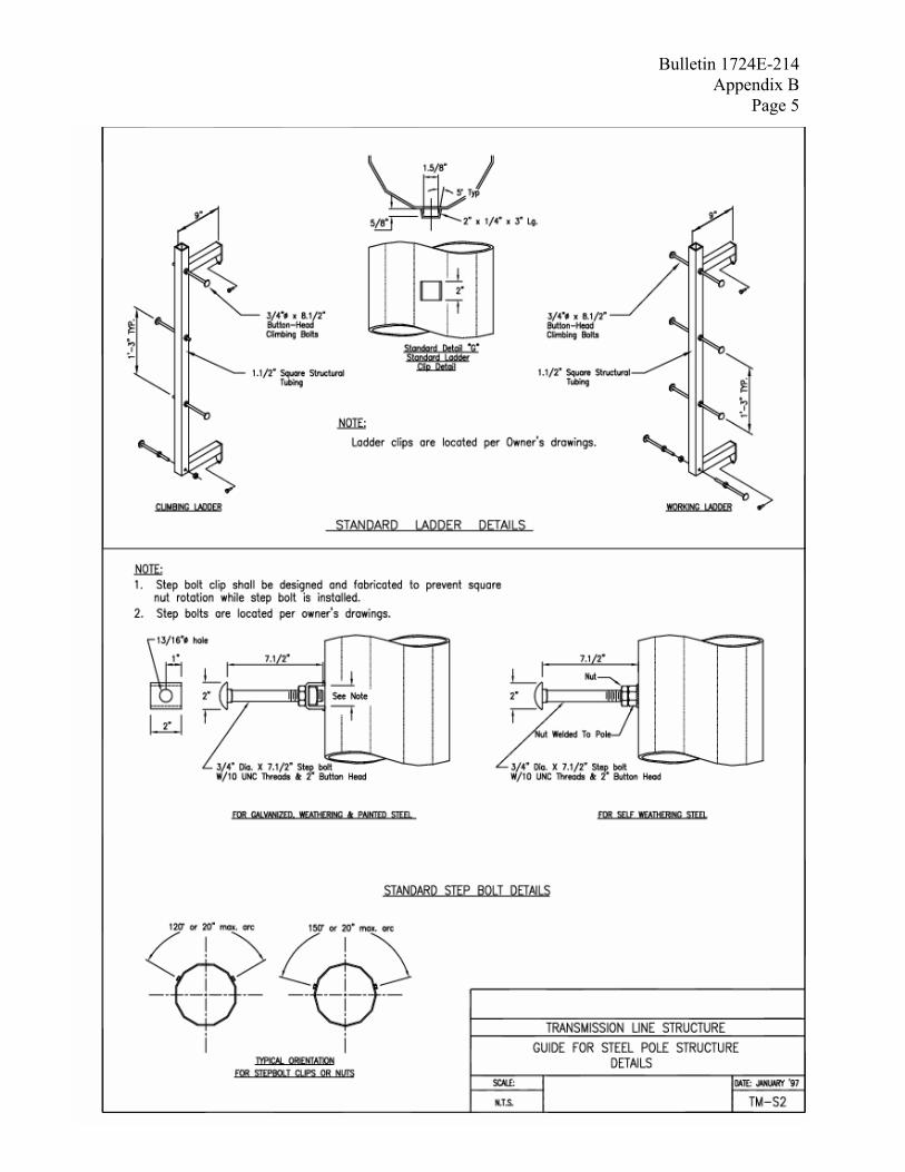
Bulletin 1724E-214 Appendix B
Page 5
Drawing TM-S2

Bulletin 1724E-214 Appendix B Page 6
BLANK PAGE
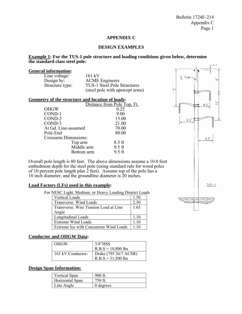
Bulletin 1724E-214 Appendix C
Page 1
APPENDIX C
DESIGN EXAMPLES Example 1: For the TUS-1 pole structure and loading conditions given below, determine the standard class steel pole: General information:
Line voltage: 161 kV Design by: ACME Engineers Structure type: TUS-1 Steel Pole Structures (steel pole with upswept arms)
Geometry of the structure and location of loads: Distance from Pole Top, Ft. OHGW 0.25 COND-1 9.00 COND-2 15.00 COND-3 21.00 At Gd. Line-assumed 70.00 Pole-End 80.00 Crossarm Dimensions: Top arm 8.5 ft Middle arm 9.5 ft Bottom arm 9.5 ft
Overall pole length is 80 feet. The above dimensions assume a 10.0 foot embedment depth for the steel pole (using standard rule for wood poles of 10 percent pole length plus 2 feet). Assume top of the pole has a 10 inch diameter, and the groundline diameter is 20 inches.
Load Factors (LFs) used in this example:
For NESC Light, Medium, or Heavy Loading District Loads Vertical Loads 1.50 Transverse. Wind Loads 2.50 Transverse. Wire Tension Load at Line Angle
1.65
Longitudinal Loads 1.10 Extreme Wind Loads 1.10 Extreme Ice with Concurrent Wind Loads 1.10
Conductor and OHGW Data:
OHGW: 3/8”HSS R.B.S = 10,800 lbs
161 kV Conductor: Drake (795 26/7 ACSR) R.B.S = 31,500 lbs
Design Span Information:
Vertical Span 900 ft. Horizontal Span 750 ft. Line Angle 0 degrees
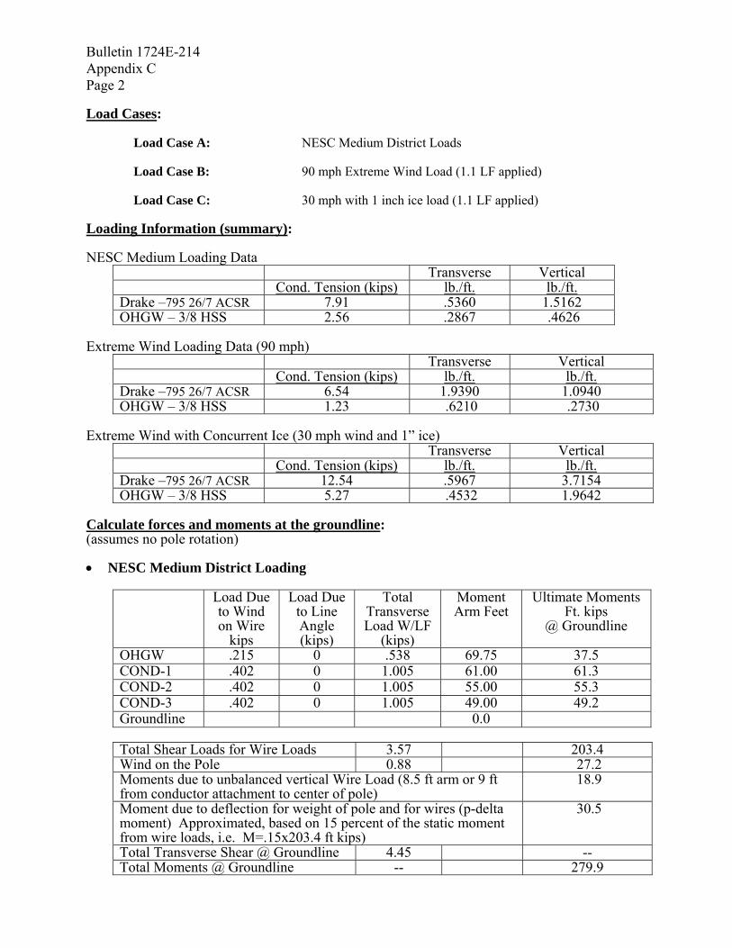
Bulletin 1724E-214 Appendix C Page 2 Load Cases:
Load Case A: NESC Medium District Loads Load Case B: 90 mph Extreme Wind Load (1.1 LF applied) Load Case C: 30 mph with 1 inch ice load (1.1 LF applied)
Loading Information (summary): NESC Medium Loading Data
Transverse Vertical Cond. Tension (kips) lb./ft. lb./ft. Drake –795 26/7 ACSR 7.91 .5360 1.5162 OHGW – 3/8 HSS 2.56 .2867 .4626
Extreme Wind Loading Data (90 mph)
Transverse Vertical Cond. Tension (kips) lb./ft. lb./ft. Drake –795 26/7 ACSR 6.54 1.9390 1.0940 OHGW – 3/8 HSS 1.23 .6210 .2730
Extreme Wind with Concurrent Ice (30 mph wind and 1” ice)
Transverse Vertical Cond. Tension (kips) lb./ft. lb./ft. Drake –795 26/7 ACSR 12.54 .5967 3.7154 OHGW – 3/8 HSS 5.27 .4532 1.9642
Calculate forces and moments at the groundline: (assumes no pole rotation) • NESC Medium District Loading
Load Due to Wind on Wire
kips
Load Due to Line Angle (kips)
Total Transverse Load W/LF
(kips)
Moment Arm Feet
Ultimate Moments Ft. kips
@ Groundline
OHGW .215 0 .538 69.75 37.5 COND-1 .402 0 1.005 61.00 61.3 COND-2 .402 0 1.005 55.00 55.3 COND-3 .402 0 1.005 49.00 49.2 Groundline 0.0
Total Shear Loads for Wire Loads 3.57 203.4 Wind on the Pole 0.88 27.2 Moments due to unbalanced vertical Wire Load (8.5 ft arm or 9 ft from conductor attachment to center of pole)
18.9
Moment due to deflection for weight of pole and for wires (p-delta moment) Approximated, based on 15 percent of the static moment from wire loads, i.e. M=.15x203.4 ft kips)
30.5
Total Transverse Shear @ Groundline 4.45 -- Total Moments @ Groundline -- 279.9

Bulletin 1724E-214 Appendix C
Page 3
TOTAL GROUNDLINE MOMENT FOR MEDIUM LOADING DISTRICT = 279.9 ft.-kips • Extreme Wind Load and Extreme Ice with Concurrent Wind Load
Similar calculations are performed for the extreme wind load and extreme ice with concurrent wind loads:
TOTAL GROUND LINE MOMENT FOR THE EXTREME WIND LOAD = 418 ft-kips TOTAL GROUNDLINE MOMENTS FOR EXTREME ICE WITH CONCURRENT WIND LOADS…………………………………………….= 165.ft-kips
• Conclusions: The Extreme Wind Loading Case controls design. Determine which “standardized” steel pole design to use:
Distance 2’ from top to groundline = 70’ – 2.0’ = 68' Load 2’ from the top to cause a 332 ft.-kip moment at groundline: = 417 ft-kips/68’ = 6140 lbs. Based on the above calculated tip load and from Table 1 of the specification, use a S-06.5 pole Perform a quick check to verify the assumed embedment depth using RUS Bulletin 1724E-205, “Design Guide: Embedment Depths for Concrete and Steel Poles”.
Discussion: Based on the results above, the extreme wind load case controls the design. Results from a computer program which uses finite element analysis are summarized in the table below. The results compare manual linear calculations with an estimate of secondary moments to the results from a computer program which performs a nonlinear analysis. The NESC allows the use of span factors and height adjustment factors when considering extreme wind loads (refer to RUS Bulletin 1724E-200, Design Manual for High Voltage Transmission Lines, Chapter 11). From the summary below, several conclusions can be made. The results from manual calculations and the computer analysis using finite elements are close, the major difference occurring with the estimate of secondary moments in the manual calculations. Also, the use of span factors and height adjustment factors will impact the design reactions. When using span factors and height adjustment factors, the selected ‘standardized’ steel pole would be:
Load 2 ft from the top to cause a 334. ft kip moment (non linear analysis and span and height adjustment factors) = 4930 lbs
Based on the above calculated tip load and from Table 1 of the specification, use a S-05.7 pole

Bulletin 1724E-214 Appendix C Page 4
Load Case
Groundline Moments based
on manual calculations with an estimate of the
secondary moments (15% of
static moment)
Groundline Moments based on a nonlinear analysis
Groundline Moments based on a nonlinear
analysis and using span and height adjustment
factors
Load Case A NESC Medium Loading 279 276 N.A. Load Case B Extreme Wind Load 417 401 334 Load Case C Extreme Ice with Concurrent Wind
163 176 N.A.
In this example, if span factors and height adjustment factors are applied in calculating the unit loads, the standard size class steel pole will be reduced by one class. Example 2: An existing 161 kV single pole line is composed of Douglas Fir wood poles. In several locations, steel poles are to replace wood pecker damaged wood poles. The existing damaged poles are 80 ft class 1 wood poles with the TUS pole top assembly. Determine which standard size steel pole should be used to replace the wood pole. Extreme wind design load is 20.7 psf (90 mph). The line is located in the heavy loading district. The conductor is 795 ACSR Drake and the overhead groundwire is 3/8" HSS. NESC heavy district loads with an strength factor of .65 and a load factor of 2.5 controlled the design of the original wood pole line. However, a quick comparison of the unit loads for the extreme wind and the NESC heavy district load with load factors and strength factors for steel, indicates that the extreme wind load will control the design of the steel pole.1 Because the extreme wind case controls design of the steel replacement pole, the engineer may use Table A-2 for convenience. Table A-2 indicates that for a class 1 wood pole, a S03.5 may be used. There may be other issues in matching classes of wood poles to steel poles that the engineer may need to consider. This example, however, shows the importance of determining the loading condition that controls the design of the steel pole. If the engineer had assumed that the NESC heavy district load controlled design of the steel pole replacement since it controlled the design of the wood pole when initially installed, then Table A-1 would have been mistakenly used and a S02.9 would have been selected as the replacement pole. Note 1: Unit loads for extreme wind is 1.9113 lbs/ft, or 2.102 with a 1.1 LF and for the NESC heavy district load, the unit load is 1.7567 lbs/ft (.7027 times 2.5) with a 2.5 LF.
Bulletin 1724E-214 Appendix D
Page 1
APPENDIX D
SELECTED METRIC CONVERSIONS

Bulletin 1724E-214 Appendix D Page 2
APPENDIX D
SELECTED METRIC CONVERSIONS
AREA To Convert From To Multiply by circular mil (cmil) square meter (m2) 5.067075 E-10 square centimeter (cm2) square meter (m2) *1.000 E-04 square foot (ft2) square meter (m2) *9.290304 E-02 square inch (in2) square meter (m2) *6.451600 E-04 square kilometer (km2) square meter (m2) *1.000 E+06 square mile (mi2) square meter (m2) 2.589988 E+06
FORCE To Convert From To Multiply by kilogram force (kgf) Newton (N) *9.806650 kip Newton (N) 4.448222 E+03 pound force (lbf) Newton (N) 4.44822
FORCE PER LENGTH To Convert From To Multiply By kilogram force per meter (kgf/m) Newton per meter (N/m) *9.806650 pound per foot(lb/ft) Newton per meter (N/m) 1.459390 E+01
DENSITY To Convert From To Multiply By pound per cubic inch kilogram per cubic (lb/in3) meter (kg/m3) 2.767990 E+04 pound per cubic foot kilogram per cubic (lb/ft3) meter (kg/m3) 1.601846 E+01
LENGTH
To Convert From To Multiply By foot (ft) meter (m) 3.048 E-01 inch (in) meter (m) *2.540 E-02 kilometer (km) meter (m) *1.000 E+03 mile (mi) meter (m) *1.609344 E+03 *Exact Conversion.

Bulletin 1724E-214 Appendix D
Page 3
Selected SI-Metric Conversions, Cont.
LOAD CONCENTRATION To Convert From To Multiply By pound per square kilograms per square inch (lb/in2) meter (kg/m2) 7.030696 E+02 pound per square kilograms per square foot (lb/ft2) meter (kg/m2) 4.788026 ton per square kilograms per square foot (ton/ft2) meter (kg/m2) 9.071847 E+02
PRESSURE
To Convert From To Multiply By kip per square inch (kip/in2) Pascal (Pa) 6.894757 E+06 kip per square foot (kip/ft2) Pascal (Pa) 4.788026 E+04 Newton per square meter (N/m2) Pascal (Pa) *1.000 pound per square foot (lb/ft2) Pascal (Pa) 4.788026 E+01 pound per square inch (lb/in2) Pascal (Pa) 6.894757 E+03
BENDING MOMENT To Convert From To Multiply By kilogram force meter (kgf-m) Newton meter (N-m) *9.806650 kip-foot (kip-ft) Newton meter (N-m) 1.355818 E+02 pound-foot (lb-ft) Newton meter (N-m) 1.355818
VELOCITY
To Convert From To Multiply By foot per second(ft/s)meter per second (m/s) *3.048 E-01 kilometer per hour (km/h) meter per second (m/s) 2.777778 E-01 mile per hour(mi/h) meter per second (m/s) 4.370300 E-01 meter per hour(m/h) meter per second (m/s) 2.777778 E-04 *Exact Conversion.

Bulletin 1724E-214 Appendix D Page 4
BLANK PAGE