Bulker Q&As and CIs on the IACS CSR Knowledge Centre … · ... the sea load can be reduced a hatch...
30
IACS Common Structural Rules Knowledge Centre Bulker Q&As and CIs on the IACS CSR Knowledge Centre KCID No. Ref. Type Topic Date completed Question/CI Answer Attach ment 224 9/2.3.1.2 Question stiffeners 2006/11/22 This requirement is excessive than our experience. In structural design, stiffeners are suitably arranged on floors to prevent excessive vibration of them. And scantlings are determined taking account of vibration. The CSR doesn't take into account the vibration effects for the scantlings, as it is outside the scope of classification.The floor webs are to be stiffened enough to withstand the forces induced by rudder post, propeller post and rudder horn.As a direct calculation of floors and their stiffening arrangement is generally never carried out in this area, it is preferable to indicate a value for the maximum spacing of web stiffeners. 225 9/3.3.1.3 Question frame spacing 2006/11/29 This requirement is excessive than our experience. This requirement should be reconsidered taking account of present designs.Please revise the rule as follows, or delete the rule:"not greater than 5 frame spacing According to the last sentence of [3.1.3], wider spaces may be accepted based on the discretion of the Society. This sentence has been added to respond the comments from Industry. Therefore, the text is kept as it is. 227 9/4.5.3.1 Question shear area 2006/11/22 It seems that the equation of Ash is missing. Please confirm. The formula is not missing, but the words "and the shear area Ash, in cm2," should be deleted. 249 attc 9/2.5.1.3 Question Connection of aft peak structure with rudder horn 2006/12/1 The vertical extension of the hull structure is required not to be less than the horn height. This requirement is considered primitive without detailed strength basis. Normally, the vertical extension is between outer shell and steering gear flat and there may be many designs that could not comply with this requirement. Please delete this requirement or amend it considering strength basis. The feedback is noted and we will consider a rule change proposal. Y 269 Table 9.1.2 Question Min plate thickness 2006/11/23 We can not see the reason for IACS to change the coefficient from 0.7 to 0.9 on the denominator of the second term in the equation. The proposal will reduce the required plate thickness at intact condition and bow flare area. We would like to stress that plating cannot be treated in the same way as a IACS stiffener where the corresponding coefficient is 90% (i.e. 0.9) of the yielding. Propose to remain as it is. The reason of changing the coefficient from 0,7 to 0,9 is a matter of editorial correction, which was forgotten at the time of publication.This coefficient if normally equal to 0,9 as defined in Table 6 in Chapter 6, Section 1 for platings not contributing to the hull girder longitudinal strength. 270 Table 9.2.2 Question Min plate thickness 2006/11/23 We can not see the reason for IACS to change the coefficient from 0.7 to 0.9 on the denominator of the second term in the equation. The proposal will reduce the required plate thickness at intact condition and bow flare area. We would like to stress that plating cannot be treated in the same way as a IACS stiffener where the corresponding coefficient is 90% (i.e. 0.9) of the yielding. Propose to remain as it is. The reason of changing the coefficient from 0,7 to 0,9 is a matter of editorial correction, which was forgotten at the time of publication.This coefficient if normally equal to 0,9 as defined in Table 6 in Chapter 6, Section 1 for platings not contributing to the hull girder longitudinal strength. Page 1 of 22
Transcript of Bulker Q&As and CIs on the IACS CSR Knowledge Centre … · ... the sea load can be reduced a hatch...

IACS Common Structural Rules Knowledge Centre
Bulker Q&As and CIs on the IACS CSR Knowledge Centre
KCIDNo. Ref. Type Topic Date
completed Question/CI Answer Attachment
224 9/2.3.1.2 Question stiffeners 2006/11/22This requirement is excessive than our experience. In structural design,stiffeners are suitably arranged on floors to prevent excessive vibration ofthem. And scantlings are determined taking account of vibration.
The CSR doesn't take into account the vibration effects for the scantlings, as itis outside the scope of classification.The floor webs are to be stiffened enoughto withstand the forces induced by rudder post, propeller post and rudderhorn.As a direct calculation of floors and their stiffening arrangement isgenerally never carried out in this area, it is preferable to indicate a value forthe maximum spacing of web stiffeners.
225 9/3.3.1.3 Question framespacing 2006/11/29
This requirement is excessive than our experience. This requirement shouldbe reconsidered taking account of present designs.Please revise the rule asfollows, or delete the rule:"not greater than 5 frame spacing
According to the last sentence of [3.1.3], wider spaces may be acceptedbased on the discretion of the Society. This sentence has been added torespond the comments from Industry. Therefore, the text is kept as it is.
227 9/4.5.3.1 Question shear area 2006/11/22 It seems that the equation of Ash is missing. Please confirm. The formula is not missing, but the words "and the shear area Ash, in cm2,"should be deleted.
249attc 9/2.5.1.3 Question
Connectionof aft peak
structure withrudder horn
2006/12/1
The vertical extension of the hull structure is required not to be less than thehorn height. This requirement is considered primitive without detailed strengthbasis. Normally, the vertical extension is between outer shell and steeringgear flat and there may be many designs that could not comply with thisrequirement. Please delete this requirement or amend it considering strengthbasis.
The feedback is noted and we will consider a rule change proposal. Y
269 Table9.1.2 Question Min plate
thickness 2006/11/23
We can not see the reason for IACS to change the coefficient from 0.7 to 0.9on the denominator of the second term in the equation. The proposal willreduce the required plate thickness at intact condition and bow flare area. Wewould like to stress that plating cannot be treated in the same way as a IACSstiffener where the corresponding coefficient is 90% (i.e. 0.9) of the yielding.Propose to remain as it is.
The reason of changing the coefficient from 0,7 to 0,9 is a matter of editorialcorrection, which was forgotten at the time of publication.This coefficient ifnormally equal to 0,9 as defined in Table 6 in Chapter 6, Section 1 for platingsnot contributing to the hull girder longitudinal strength.
270 Table9.2.2 Question Min plate
thickness 2006/11/23
We can not see the reason for IACS to change the coefficient from 0.7 to 0.9on the denominator of the second term in the equation. The proposal willreduce the required plate thickness at intact condition and bow flare area. Wewould like to stress that plating cannot be treated in the same way as a IACSstiffener where the corresponding coefficient is 90% (i.e. 0.9) of the yielding.Propose to remain as it is.
The reason of changing the coefficient from 0,7 to 0,9 is a matter of editorialcorrection, which was forgotten at the time of publication.This coefficient ifnormally equal to 0,9 as defined in Table 6 in Chapter 6, Section 1 for platingsnot contributing to the hull girder longitudinal strength.
Page 1 of 22
IACS Common Structural Rules Knowledge Centre
KCIDNo. Ref. Type Topic Date
completed Question/CI Answer Attachment
271 9/5.2.4.3 Question watertight 2006/11/23 IACS's proposal to change the word "watertight" into "weathertight" is notacceptable unless there is a Load line coaming. Propose to retain watertight.
The change from watertight to weathertight is correct. LL Regulation requestsa coaming heigth of 600mm for Pos.1 and 450mm for Pos.2. Subject to thisthe access hatches need to be weathertght only. In the CSR text in para. 2.4.1we refer to the required coaming height. Consequently the access hatches asmentionend under para. 2.4.3 have to fulfill the requirement 'weathertight'. Weassume the questioner has mixed this with flushdeck hatches. They have tobe watertight.
301 9/5.1.5.1& Table
9.5.2Question
Allowablestresses of
externalPressure
2006/12/21
The external Pressure of 0.8 / 0.46 ReH allowable stresses in table 2 of Ch 9,Sec 5, 1.5.1, it is subjected to Ch 4, sec 5, [2], we think that the correct oneshould be subject to Ch 4, sec 5, [2.2]; the other loads are water ballast load,cargo load and container load etc. If not, please inform us what other loadsare with the detail load.|
The Table 2 of Ch 9 Sec 5 is correct. The other loads specified in Table 2 areinterpreted as internal loads such as inertia pressure due to water ballast inballast hold.
304 9/5.4.2.1 Question hatchcoaming 2007/1/31
Regarding to the load point, some classes require to use the hatch cover top,but others are still on the top of hatch coaming yet. Which is correct one, ontop of hatch cover or top of coaming? If the load point is based on top ofcoaming, the sea load can be reduced a hatch cover depth height (900-1200mm) from coaming to hatch cover top. We propose that load point on top ofcover is for the sea load, on top of coaming is for water ballast load.
The proposal is agreed, but should be more specific on the location of the loadpoint. Regarding the second and last points in Ch 9, Sec 5, [4.2.1], we willconsider the rule correction as follows: "- transversely, at hatchway side, -vertically, at the top of the hatch cover for sea pressures, and at the top of thehatch coaming for internal pressures due to ballast water."
305 9/5.7.5 QuestionCleat for
water ballastload
2006/12/26Because the internal WB loads of CSR are very large on hatch cover bottomside, we advice that an allowable stress of cleat is needed, and propose it is0.9-1.0 ReH. As some class have an allowable and some have not it.
As [7.3] and [7.5] are coming from UR S21, the dimensioning of cleats iscovered under [7.3.5], whatever the loads are.
309attc Ch 9/ 5 Question hatch cover 2006/12/21
Regarding to the triangular load like water ballast, both way of triangular loadand average uniformed load may be used based on class by class or localoffice by office, but both calculation results is very different. What’s CSRstandard for folding and side rolling hatch cover from 1 to 5 (see attachment)?
The load cases are “H1” and “H2”, the internal pressure due to water ballast inballast hold is treated as uniform load. The load cases are “P1”, “P2”, “R1” and“R2”, the internal pressure due to water ballast in ballast hold is treated astriangular load.
Y
312 9/1.4.4.4& 9/2.4.3.4 Question FEA 2007/1/31
Which sub-section should be adopted to determine the scantlings of deckprimary supporting members of the fore part and the aft part in accordancewith Ch 6/Sec.4? For example, if the ship length L is 150m or above, thedirect strength analysis would be applied according to the provision specifiedin Ch 7(see Ch 6/Sec 4/[1.3.1]), but the procedure in Ch 7 is applied on thecargo hold structures in midship area.
For ships greater than 150 m in length, Ch 6, Sec 4 requires normally FEAanalysis. However, in the fore and aft parts, it seems that prescriptiveformulae may be used instead of FEA. In such a case, the requirements in Ch6, Sec 4, [2.6] may also be considered as being applicable to primarysupporting members in fore and aft parts for ships greater than 150m. Wewill consider the further rule development about the application of FEA tocargo areas outside midship region and determination of the scantling ofprimary supporting members outside midship cargo regions for ships of 150min length and above.
Page 2 of 22
IACS Common Structural Rules Knowledge Centre
KCIDNo. Ref. Type Topic Date
completed Question/CI Answer Attachment
336attc 9/5.5.5 Question Section
modulus 2007/2/8
We would like to confirm a way to apply the requirement of this sub-paragraphto a structural member shown in the attachment.(1) Which position, A, B or C, shown in Figure, is to be selected to calculatew0 and I0? We consider that position B is suitable for this requirement. Pleaseconfirm.(2) Which position, A, B, C or else, is to be considered when the requirementof net section modulus of ordinary stiffeners, w, is applied? We consider thatposition A is appropriate for this requirement. Please confirm.
According Fig. 1 a symmetrical beam with l_1 < 0.5 l_0 is the basis for thissimplification. The example in the attachment is not covered by theassumptions of the requirement, i.e., a symmetrical beam. For anunsymmetrical beam as shown the attached document, the calculation shouldbe carried out by direct calculations or beam analysis as stated in [5.4.1].
Y
376Table
9/3.7.2 &Table 2
Question net thickness 2007/1/24 Ch.9 Sec.3 [7.2] Table 2. We assume the bedplate net thickness is in mm, notm. We agree with the comment and will consider a rule amemdment proposal.
377 9/5.2.2 Question formula 2007/1/24 Ch.9 Sec.5 [5.2.2] The first formula is incorrect? Should read t=10s, nott=0.01s We agree with the comment and will consider a rule amemdment proposal.
378 9/5.5.5.1 Question formula 2007/3/12
Our understanding of this item is that the section modulus for a stiffener/PSMwith variable cross section always is to be at least equal to the sectionmodulus of a stiffener/PSM with constant cross section ( w = wCS ). Thismeans there is nothing to gain by varying the cross section. Example: For asimply supported PSM with constant CS the section modulus at midspan, w0,will be governing. Our understanding is that for a PSM with varying CS, theminimum section modulus is w0, independent of the position along the axis (w = wCS = w0 ). We have the same problem for moment of inertia. Pleaseclarify.
With respect to the names given in 9/5.5.5.1, considering wCS=w0 gives asection modulus of wCS=w0 only if w1>=0.8*w0, i.e only if the stiffener/PSM'scross section is not really varying. For 0=<w1=,0.8*w0, the section modulus tobe considered is given by the second formula and is greater than the midspansection modulus w0. In addition, we can consider that the midspan sectionmodulus w0 is not to be equal to the section modulus of an constant crosssection stiffener/PSM for this calculation; it has to be used for the 9/5.5.5.1. Asimilar approach can be applied to inertias. Furthermore, these calculationscan be replaced by a direct approach as it is usually made.
379 9/5.6.3.1 Question formula 2007/2/22 Ch.9 Sec.5 [6.3.1] What is the background for the factor 15.98 in this formula?Is it a misprint for 15.8?
This formula comes from IACS UR S21, S21.4.2. The constant value 15.98is obtaind from muttiplying 14.9 by squareroot of 1.15 (=Scoam specified inUR S21.4.2). Therefore, the formula is correct.
413Table
9.3.2 &9/3.7.2
CINet Sectional
area ofbedplates
2007/10/8
Ch.9 Sec. 3 [7.2] Table 2The requirement for net sectional area of bedplates is significantly exceedingcurrent designs, in some cases by more than 50%.The requirement for a typical Handymax vessel with current design hasP=9500kW, nr = 130, LE=8.5mThe required bedplate net area is 640cm2. Current design is about 430cm2,which is a nearly 50% increase.
It was not intended to increase the scantlings compared to current design.We noted your comment. The following interpretation are prepared and will besubmit it to the Hull Panel for review."The net scantlings of the structural elements in way of seatings are to bedetermined by the engine manufactures. They are to be checked on the basisof calculation result supplied by the engine manufacturers. If thesecalculations are not supplied, the net scantlings of the structural elements inway of the internal combustion engine seatings are to be obtained from theformulae in Table 2."
Page 3 of 22

IACS Common Structural Rules Knowledge Centre
KCIDNo. Ref. Type Topic Date
completed Question/CI Answer Attachment
468
9/4.4.1.1,4.2.1,
4.5.1 &5.3.2
CI
Scantlings ofs/structures
&deckhouses
2009/10/6
According to Ch 3 Sec 2 [2.1.1], the scantling of superstructure anddeckhouses specified in Ch 9 Sec 4 is based on the gross scantling concept.Also, according to Ch 9 Sec 4, [1.2.1], all scantling and dimensions refered toin [4] and [5] are gross. In the requirement of [4.1.1], [4.2.1], [4.5.1] and[5.3.2], the thickness formulae are given as follows.
[4.1.1] t=1.21s*(k*pSI)^0.5+tc,[4.2.1] t=1.21s*(k*PD)^0.5+tc,[4.5.1] t=8s*(k)^0.5+tc,[5.3.2] t=0.9s*(kpA)^0.5+tc
Where, tc is defined as corrosion addition defined in Ch 3, Sec 3, specified in"Symbols". To refference to the corrosion addition defiend in Ch 3 Sec 3means that the scantling is based on the net scantling concept. This isinconsistet with the requirement in Ch 3 Sec 2 [2.1.1] and Ch 9 Sec 4 [1.2.1].According to Technical Background, these formulae are based on the currentGL Rules. In the original formula, tk instead of tc is used and tk is taken equalto 1.5mm. Please consider revising the text.
As you pointed out, the reference to the corrosion addition, tc, defined in Ch 3Sec 3 in the formulae is inconsistent with the requirements in Ch 3 Sec 2[2.1.1] and Ch 9 Sec 4 [1.2.1]. These requirements have come from thecurrent GL Rules and there are no intention to modify the scantling approachconcept specified in Ch 9 Sec 4 [1.2.1]. Therefore, the value of tc used inthese formulae is taken equal to 1.5mm as an interpretation, according to thecurrent GL Rules. This has been reflected in RCN 1-7 to the July 2008 Rules.
476attc 9/5.1.5.1 CI
Allowablestress on
hatch covers2007/8/23
Ch. 9 Sec. 5 1.5.1. Allowable stress on hatch covers:Reference in the rule text is made to ILLC Reg.15(6) and 16(5).Regulation 15(6) is relevant for “Hatchways closed by portable covers andsecured weathertight by tarpaulins and battening devices”. The allowablestress for pontoon hatch covers given as Sigma_A = 0.68ReH is originatingfrom Reg. 15(6).Regulation 16(5) is relevant for “Hatchways closed by weathertight covers ofsteel or other equivalent materials. The allowable stress for “weathertighthatch cover” Sigma_A = 0.8 ReH is originating from Reg. 16(5).It is our interpretation that 15(6) is not relevant for modern bulk carriers. URS21 and UI LL70 are both covering Reg. 16 and relevant for pontoon hatchcovers. We assume that Pontoon hatch covers in modern bulk carriers shouldbe treated as “weathertight hatch covers” with allowable stress Sigma_A =0.8ReH. This is not clear as Table 2 is written in the current rules.
The Common Interpretation is as follows:- If hatch covers are considered weathertight by construction, and withoutthe need of tarpaulins and battening devices, the allowable stresses to beused are those corresponding to the line "Weathertight hatch cover" in theTab 2, i.e. 0.8ReH for sigma. This is in line with ILLC Reg.16(5).- If hatch covers are considered weathertight by using tarpaulins and batteningdevices, the allowable stresses to be used are those corresponding to the line"Pontoon hatch cover" in the Tab 2, i.e. 0.68ReH for sigma. This is in line withILLC Reg.15(6).
Y
477 9/5.5.2.3 QuestionCritical
bucklingstress
2007/10/4
Ch. 9 Sec. 5 5.2.3 Critical buckling stress check. Last sentence of therequirement states: “In addition, the bi-axial compression stress in the hatchcover plating, when calculated by means of finite element analysis, is tocomply with the requirements in Ch.6 Sec.3” We assume the sentenceoriginates from UR S21 3.6. In case of FEM analysis, please advise if biaxialbuckling in accordance with requirement of Ch. 6 Sec. 3 is additional orinstead of the uniaxial buckling requirement in 5.2.3.
The Common Interpretation is as follows:- If no finite element analysis is performed for the buckling of the hatch coverplating, only the criteria for buckling for uniaxial compression is to be checked.- If a finite element analysis is performed for the buckling of the hatch coverplating, criteria for buckling for bi-axial compression are to be checked.
Page 4 of 22
IACS Common Structural Rules Knowledge Centre
KCIDNo. Ref. Type Topic Date
completed Question/CI Answer Attachment
494
Table9.1.1 &Table9.2.1
CI Fore part &Aft part 2007/9/13
Ref. Ch. 9 Sec. 1 ”Fore Part” Table 9.1.1 and Ch. 9 Sec. 2 “ Aft Part” Table9.2.1.Q1: Tables 9.1.1 and 9.2.1 are referring to “Platform”. It is assumed that this isa non-watertight horizontal member. Please confirm.
Q2: Tables 9.1.1 and 9.2.1 are extracts of Table 6.1.2. Tables 9.1.1 and 9.2.1are incomplete with respect to horizontal and vertical watertight boundaries.Please advise if relevant items of Table 6.1.2 may be used for watertightitems in fore/aft part. Please consider completing the Tables 9.1.1 and 9.2.1with watertight divisions.
A1:Platform referred in tables 9.1.1 and 9.2.1 are effectively non-watertighthorizontal member.A2:Tables 9.1.1 and 9.2.1 are incomplete with respect to horizontal andvertical watertight boundaries, and relevant items of Table 6.1.2 may be usedfor watertight items in fore/aft part.
495 9/1.3 &9/2.2 CI
Fore part &Aft part load
model2007/9/28
Ref. Ch. 9 Sec. 1 ”Fore Part – load model” [3] and Ch. 9 Sec. 2 [3] “Aft Part -load model”Following pressures are explicitly given for calculation:1.External pressure according to Ch. 4 Sec.52.Internal lateral pressure in testing condition according to Ch.4 Sec. 6 [4]Internal pressures due to liquid ps+pw according to Ch. 4 Sec. 6 [2] is notspecified for Fore/Aft regions.Please advise if Ch. 4 Sec. 6 [2] pressures need to be considered for fore andaft regions or if only testing pressures should be applied.
it is quite clear that internal pressures defined in Ch 4, Sec 6, [2] need also tobe considered for fore and aft regions in addition of testing pressures.Also Included in Corrigenda 5
500 9/1.5.4.1 &9/1.5.4.2 CI
Loaded areabetween thesupports of
the structureconsidered
2007/9/28
In Ch 9, Sec 1, (5.4.1] and [5.4.2], a parameter A defined as "Loaded areabetween the supports of the structure considered" is used in the determinationof the net thickness of girders and floors in flat bottom forward area. Thedefinition of this parameter is not clear enough and needs interpretation, orformula to calculate it.
In 5.4.1,GirdersA is given by the following formula.A=S*lWhere,S: Spacing of center or side girders under consideration, in m.l: Span of floors under consideration, in m.
In 5.4.2, FloorsA is given by the following formula.A=S*lWhere,S: Spacing of floors under consideration, in m.l: Span of center or side girders under consideration, in m.Also Included in Corrigenda 5
524 Ch.9,Sec.1 & 2 RCP
Scantlings ofFore Part
and Aft Partstructures
2007/9/28
1) The question relates to scantlings of Fore Part and Aft Part structures inflooding condition(Ch.9, S.2, 1.1.2).It being noted that there is no specific paragraph in Fore Part referring to needof scantling assessments in case the fore part is arranged with floodablespaces other than the fore peak tank, it is requested that the requirement inCh.9, S.2,1.1.2 be incorporated in Fore Part, as well.2) In Ch.9, S.1 and S.2, there is no requirement of net minimum thickness ofplating for watertight bulkhead, while CSR Tanker Rules specify. It isrequested that net minimum thickness of plating for watertight bulkhead inFore Part and Aft Part be specified.
1) We noticed your advice and will prepare a rule change accordingly.
2) Tables 9.1.1 and 9.2.1 are incomplete with respect to horizontal and verticalwatertight boundaries, and relevant items of Table 6.1.2 may be used forwatertight items in fore/aft part.
Page 5 of 22

IACS Common Structural Rules Knowledge Centre
KCIDNo. Ref. Type Topic Date
completed Question/CI Answer Attachment
1. Ch 9 Sec 5 [5.3.2] and [5.4.2]We think it is wrong in Ch 9 Sec 5 [5.3.2] and [5.4.2] to link both minimumthickness of web of primary supporting member and ordinary stiffeners withtnet = 6 mm & tnet = 10s of hatch cover top plate on Ch 9 Sec 5 [5.2.2] in thefollowing reasons.(1) The minimum net thickness specified in Ch 9 Sec 5 [5.2.2] is required forsteel plating forming the tops of hatch covers by ILLC Reg.16 (5) (c) which isonly applied to the top plate, not to the web of primary supporting membersand ordinary stiffeners.(2) If the current ordinary stiffener size L 125*75*7 or stiffener with a U-profileare satisfied with the strength requirement specified in IACS UR S21, thestiffener spacing is required to be reduced to 450 to 500 from 600 or 700 mmso that it complies with the minimum net thickness [tnet = 10s] specified inCh9 Sec5 [5.2.2]. In addition, the web thickness of such stiffeners is increasedby 1 to 2mm due to the minimum net thickness of 6mm.
The stiffener weight of the hatch cover will be increased about 40% comparedto the current one which satisfies the requirements of IACS UR S21.Therefore, we propose to revise the requirement for minimum net thicknessrequirement for webs of primary supporting members and ordinary stiffenersspecified in Ch 9 Sec 5 [5.3.2] and [5.4.2], respectively.
536 9/5.1.4.1 QuestionStiffenerswith a U-
profile2007/10/26
Ch 9 Sec 5 1.4.1 Corrosion additions(1) Box type stiffeners such as stiffeners with a U-profile are used in manyhatch covers. The internal environment in a stiffener with a U-profile is similarto the one for internal structures of double skin hatch covers.Therefore, we consider that the total corrosion addition for such stiffenersshould be 1.5mm for single skin hatch covers.Please clarify the requirement on the corrosion addition of such stiffeners.(2) In applying a finite element analysis in order to evaluate the stresses in theprimary supporting members of hatch covers, are FE models considered a fullcorrosion addition or a half corrosion addition?(3) In calculating the net moment of inertia of a primary supporting member,does a full corrosion addition subtract from the gross offered thickness of aprimary supporting member?
1) As pointed out by the questioner, the corrosion environment inside of a box-type stiffener may be the same of the inside of double skin hatch cover, butthe corrosion environment outside of a box type stiffener is the same of thecargo side of a hatch cover. Therefore a corrosion addition of 2mm has to beapplied.
2) We think that full corrosion addition has to be considered, because incomparison of the hatch cover to the bulk carrier hull it can be assumed, thatthe whole hatch cover structure may corrode simultaneously, because theenvironmental conditions are not so different.
3) When calculating the net moment of inertia of a primary supportingmember, full corrosion addition has to be considered to be in line with S21.3.5and the design approach in Ch6.
2007/10/26
In Ch 9, Sec 5, [5.3.2],the web minimum net thickness of the ordinarystiffener, in mm, is to be not less than 4 mm.In Ch 9, Sec 5, [5.4.2],the web minimum net thickness of the primarysupporting member, in mm, is to be not less than 6 mm.
535 9/5.5.3.2 &9/5.5.4.2 RCP
Minimumthickness of
web ofprimary
supportingmember and
ordinarystiffeners
Page 6 of 22
IACS Common Structural Rules Knowledge Centre
KCIDNo. Ref. Type Topic Date
completed Question/CI Answer Attachment
537 Table9.5.2 Question
Weathertighthatch coversand pontoonhatch covers
2007/10/19
3.Ch 9 Sec 5 Table 2(1) The allowable stress for weathertight hatch covers and pontoon hatchcovers subjected to external pressure are 0.80 ReH and 0.68 ReH,respectively, in accordance with Reg.15 and Reg.16 of ILLC, but the allowablestress for both weathertight hatch covers and pontoon hatch covers subjectedto other loads is the same.Why does the same allowable stress apply to the different types of hatchcover?Please clarify.(2) According to ILLC, external pressure is only external wave pressure actingon the hatch cover. As CSR considers 4 load cases, i.e., H, F, R and P, theexternal pressure for R1, R2, P1 and P2 at any point of an exposed deck isconsidered, in addition to the external pressure for load cases H1, H2, F1 andF2, that is the same as IACS UR S21. Therefore, we understand that“External pressure, as defined in Ch 5 Sec 5, 2” means the external pressurespecified in Ch 4 Sec 5 [2.2] and [2.3] and does not include “Load carried onexposed deck” specified in Ch 4 Sec 5 [2.4].We also understand that other loads in Table 2 mean “load carried onexposed deck” and internal pressure due to liquid in ballast hold specified inCh 4 Sec 6 [2]Please confirm.
A1: For loads which are different from ILLC sea loads, the practice of someclassification Societies, since many years, is to consider an allowable stressdifferent from the one indicated by ILLC and applicable for all types of hatchcovers.A2: This is related to question 527 and your interpretation is correct:- external pressures are sea pressures- other loads are those defined in Ch9 Sec5 [4.1.3] to [4.1.6].
538 9/5.5.2.3 CI
Stresses inthe primarysupportingmember
2008/4/11
4.Ch 9 Sec 5 [5.2.3](1) Where the stresses in the primary supporting member are evaluated byFEA, the uni-axial buckling check can be omitted since the buckling strengthcheck using the bi-axial compression stress in the hatch cover plating iscarried out in accordance with the requirements of Ch 6 Sec 3.Please confirm.(2) As there is no stiffener buckling factor "c" or F1 in Table 1 of Ch 6 Sec 3for special shape stiffeners such as a stiffener with a U-profile, please makean interpretation for the buckling factor of a stiffener with a U-profile.
A1 The Common Interpretation is as follows:- If no finite element analysis is performed for the buckling of the hatch coverplating, only the criteria for buckling for uniaxial compression is to be checked.- If a finite element analysis is performed for the buckling of the hatch coverplating, criteria for buckling for bi-axial compression are to be checked.
A2According to the stuffiness of the stiffener with U-profile, we think thecoefficient factor F1 is acceptable to the same value for girders specified inTable 1 of Ch 6 Sec 3, i.e., F1 = 1.30.However a higher F1 value than 1.30 may be accepted provided the bucklingstrength of panel stiffened by U-beams is verified by non-linear bucklinganalysis using FEA.
543
Ch.9Sec.1,
Sec.2 andSec.3
CI
Scantlings ofPSMs in
Fore Part, AftPart & E/R
2007/10/23
Although scantling of PSMs in Fore part, Aft part and E/R are regulated in Ch9Sec1 through Sec3 in CSR, scantling requirement for not all the PSMs areregulated in Ch9.Scantling requirements of some of the PSMs, such on decks or deep tankbulkheads, refer to Ch6 Sec4. In Ch6 Sec4, scantling formulas are regulatedfor ships having ship’s length L less than 150m, and direct strength analysis isrequired for ships having L=150m or more according to provisions in Ch7.However, Ch7 regulates direct strength analysis of cargo hold structures only.Please advise how to determine scantling of PSMs in Fore part, Aft part andE/R for ships having L=150m or more.
According to the agreed answer of question #312, PSM in the fore and aft partof the vessel may be designed according Ch6, Sec4, 2.6.We will consider the further rule development about the determination of thescantling of primary supporting members outside midship cargo regions forships of 150m in length and above.
Page 7 of 22

IACS Common Structural Rules Knowledge Centre
KCIDNo. Ref. Type Topic Date
completed Question/CI Answer Attachment
582attc 9/3.2.1.9 CI Manhole
Dimensions 2008/2/7
Chapter 9, Section 3. [2.1.9]:1) The 2nd paragraph has the general requirements for the manhole size infloors. We note that many ships are designed with two separate tanksvertically in way of main engine bed. The access manholes exceeding theabove size limit due to lower floor height in way are designed in each upperand lower tanks as shown in the attachment. We understand that sucharrangement may be acceptable provided the shear area of the floor is notless than that with the hole of 40% of floor local depth based on minimumrequired thickness in way and the local strength is satisfied. Please confirm orotherwise advise.2) We understand that the requirements in paragraph 2 of 9-3/2.1.9 is notapplicable to girders. Please confirm.
A1 - Where access manholes dimensions exceed the size limit in Ch 9, Sec 3,[2.1.9] due to lower floor height in way, such arrangement may be acceptableprovided that the shear area of the floor is not less than that with the hole of40% of floor local depth based on minimum required thickness in way and thatthe local strength is satisfied.A2 - The requirements in paragraph 2 of 9-3/2.1.9 are also applicable togirders.
Y
559 Text 9/3 CI
Longitudinalstrength andlocal strengthof plates andstiffeners inmachinery
space
2008/4/10
Regarding the requirements of longitudinal strength and local strength ofplates and stiffeners in machinery space, our interpretations are as follows;1. Longitudinal strength1-a. Longitudinal bending and shear strength are checked according to Ch5,Sec1.1-b. Hull girder ultimate strength is checked according to Ch5, Sec2.2. Local strength of plate and stiffener2-a. Flooding requirements in Ch6, Sec1, 3.2.2 and Ch6, Sec2, 3.2.5 areapplied with considering longitudinal stress sigma_x as similar to cargo area2-b. Buckling requirements in Ch6, Sec3 3.1.2 and 4 are applied withconsidering longitudinal stress sigma_x and tau as similar to cargo areaPlease clarify above interpretations.
1. Longitudinal strength in machinery space1-a. Longitudinal bending and shear strength are checked according to Ch5,Sec1, provided flooding in machinery space needs not be considered .1-b. Hull girder ultimate strength is checked according to Ch5, Sec2, providedflooding in machinery space needs not be considered .
2. Local strength of plate and stiffener in machinery space2-a. Requirements in Ch6, Sec1, 3.2.2 and Ch6, Sec2, 3.2.5 are applied withconsidering longitudinal stress sigma_x in intact condition.2-b. Buckling requirements in Ch6, Sec3 3.1.2 and 4 are applied withconsidering longitudinal stress sigma_x and tau as similar to cargo area.
583Ch.9
Sec.3/4 &5
RCP
scantlingsfor platformstructuresand pillars
2007/3/23
9-3/4 and 9-3/5: The platforms and pillars will support the loads of machinery,independent tanks etc.. However there is no loads specified in CSR fordetermining the scantlings for platform structures and pillars. It is alsoimpracticable to obtain the dynamic loads for each machinery weight due tolack of information. Therefore, based on current CSR , it is impracticable todetermine the scantlings of platforms and pillars in engine room except theminimum plate thickness specified in CSR. As an alternative, we think thateach Class Society Rules may be used for determining the scantlings ofplatforms and pillars in addition to the minimum plate thickness requirementsspecified in CSR. Please confirm. Also suggest CSR to specify the loads forplatforms in engine room and pillars.
1) There are no specific loads in CSR BC for determining the scantlings ofplatforms in machinery spaces. There is only a minimum plate thicknessrequirement.2) For determining the scantlings of platforms and pillars in addition to theminimum plate thickness requirements specified in CSR for BC, a RuleChange will be considered in future.
Page 8 of 22
IACS Common Structural Rules Knowledge Centre
KCIDNo. Ref. Type Topic Date
completed Question/CI Answer Attachment
613Symbol9.5 & 9Sec.5
CIHatch Cover
of ballasthold
2008/4/24
Reference is made to Ch.9 Sec. 5Q1 Requirement for hatch cover of ballast holdIn Chapter 9 Sec.5 Symbols, it is stated that "FS = 0 and FW = 0.9 for hatchcovers of the cargo ballast hold". It is our understanding, these coefficients areapplicable to ballast pressure only and not sea pressure or cargo pressure. Ifso, please consider rephrasing the paragraph to"FS = 0 and FW = 0.9 for ballast pressure of hatch covers on the cargo ballasthold".Q2 Ballast pressure calculationWhen calculating ballast pressure according to Ch.4 Sec.6 [2.2] we assumethat the fixed value of (x-xB) may be utilized. (0.75lh or -0.75lh)Please confirm and if relevant, update rules accordingly.Q3 Structural calculationa. When ballast pressure or dry cargo pressure is considered for the hatchcover, please advise the formula to use in order to calculate the required platethickness, section modulus and shear area of stiffeners? Can the formula inCh.6 Sec.1 [3.2.1] and Ch.6 Sec.2 [3.2.3] or the formula in Ch.9 Sec.5 5.3.3be used?b. In Ch.9 Sec. 5 bending stresses of primary supporting members areaccounted for when calculating scantlings of local structures such as plate andstiffeners. If we use the formulas of Ch. 6 Sec. [3.2.1] and Ch. 6 Sec.2 [3.2.3],shall primary bending stress be accounted for? (Ref. lambdaP and lambdaSfactors)Please clarify the rules.
A1. Your understanding that the coefficient FS = 0 and FW = 0.9 areapplicable to ballast pressure only is right.
A2: This fixed value has to be used in prescriptive assessment of structure.
A3:Formulae as per Chapter 9, Sec.5 should be used.
620 9/5.5.4.6 QuestionError in the
formulagiving kt
2008/5/12 In Ch 9, Sec 5, [5.4.6], it seems that there is an error in the formula giving kt,which is not in accordance with UR S21. Please confirm?
It is right. The formula of kt should be modified from kt=5.35+4*(a/d)^2 tokt=5.35+4/(a/d)^2, to be in accordance with UR S21.3.6.3.This editorial correction will be issued as a Corrigenda.
654 9/1.4 Question collisionbulkhead 2008/9/10
How is the additional safety taken into account for the collision bulkhead,when not subjected to lateral loads from tanks, hence fore peak is voidspace?
The scantling of collision bulkhead is enhanced to the other bulkheads,according to Ch 6 Sec 1, [3.2.2] for bulkhead plating and Ch 6 Sec 2, [3.2.5]for ordinary stiffeners. Where the collision bulkhead is a boundary of voidspace, the scantling may be derived by considering the void space as flooded,using the requirements mentioned above. We will consider a rule change forprimary supporting members under flooded condition.
Page 9 of 22
IACS Common Structural Rules Knowledge Centre
KCIDNo. Ref. Type Topic Date
completed Question/CI Answer Attachment
1.In the course of applying CSR for Bulkers, CCS has found some problemsexisting with the CSR requirements relating to minimum scantlings of thestructural elements in way of machinery seatings, as specified in CSR BC,Chapter 9 - Other Structures, Section 3, 7.2 Minimum scantlings, which isquoted below for easy reference:"7.2.1 The net scantlings of the structural elements in way of the internalcombustion engine seatings are to be obtained from the formulae in Tab 2."2. This requirement is found to be irrational since the calculation resultsproved to be unnecessarily large.2.1 CCS is of the opinion that the internal combustion engine manufacturersare the ones who should be responsible for the design of the engine seatingssince they have the richest experience of application and the authority, andaccordingly the design of the seatings should follow thesuggestions/instructions provided by the manufactures.
3. Therefore, CCS proposes to substitute the above mentioned paragraph andtab.2 by the new "7.2.1 The net scantlings of the structural elements in way ofthe internal combustion engine seatings are to be in accordance with thescantlings provided by the manufactures."
665 9/3.4.1.2 RCP Transversespacing 2008/4/24
Transverse spacing in machinery spaceIn Ch9, Sec3, 3.1.3, the side transverse spacing is restricted upto 4/5 framespacings.On the other hand, greater spacing is also permitted at the last sentencestated below;"Side transverse spacing greater than that above may be accepted providedthat the scantlings of ordinary framesare increased, according to the Society’s requirements to be defined on acase by case basis."In Ch9, Sec3, 4.1.2, the platform transverse spacing is restricted upto 4 framespacings.Can greater spacing be permitted as similar to the above?
The primary support i.w.o. the platform is to be integrated with the primarymembers in the side. Hence where larger spacings are allowed in the side itwill result in an equally larger spacing in the platform.
666 9/1.4.4.4 &9/2.4.3.4 Question
deck primarysupportingmembers
2008/9/10
According to the answer in KC 312, the requirement of Ch6 Sec4, 2.6 isapplicable to deck primary supporting members in Fore and Aft. In calculatingthe scantling of the members in Fore and Aft according to the formulaspecified in Ch 6 Sec 4, 2.6.3, we understand that the applicable allowableshear stress and lamda_s are R_y/square root (3) and 0.9 instead of 0.4 R_yand 0.8, respectively, because the lamda_p is 0.9 in the formula for plating ofaft part specified in Ch 9 Sec 2. Please confirm the above.
Your interpretation is not right. If the scantling formulae for primary supportingmembers are used in the fore and aft part, lambda-s and the allowable shearstress, given in CH6, Sec4, are to be used (i.e. lambda-s equal to 0.8 andallowable shear stress tau-a equal to 0.4Ry). However we will consider arule change in Ch.9 Sec.1 [4.4.4] and Ch.9 Sec.2 [4.3.4] so that therequirements to primary supporting members are coherent within Ch.9 Sec.1and Ch.9 Sec.2 respectively.
663 9/3.7.2.1 RCP
minimumScantlings ofthe structural
elements
2008/5/13As the same question is uploaded on KC ID 413, please refer to the answer inKC ID 413.
Page 10 of 22
IACS Common Structural Rules Knowledge Centre
KCIDNo. Ref. Type Topic Date
completed Question/CI Answer Attachment
According to Ch.9, Sec.5, Symbols:s is defined as length, in m, of the shorter side of the elementary plate panel.My understanding to the minimum net thickness of web plate of ordinarystiffeners and primary supporting members is as follows:According to Ch.9, Sec.5, [5.3.2], The minimum net thickness of web plate ofordinary stiffeners should be (tnet)min=min(10s,6), while in the calculation, theparameter s should be of web plate panel of ordinary stiffeners (normally webheight) and should have no relation to the top plate panels of hatch cover.This understanding can also apply to determine the minimum net thickness ofweb plate of primary supporting members.
According to Ch.9 Sec.5, [5.4.2],The minimum net thickness of web plate ofprimary supporting members should be (tnet)min=min(10s,6) the parameter sshould be of web plate panel of primary supporting members (normally webheight) and also have no relation to the top plate panels of hatch cover.If the above understanding is correct, then there will be no limit to use thecurrent widely used ordinary stiffenr L125x75x7 in hatch covers of vessels withCSR BC notation.
We propose to revise the text for minimum net thickness of web plate ofordinary stiffeners and primary supporting members in Ch.9 Sec.5 [5.3.2] and[5.4.2], respectively.The formula kt in Ch.9, Sec.5 [5.4.6] should be corrected askt=5.35+4.0/(a/d)^2 or kt=5.35+4.0(d/a)^2.
686 9/5.5.2.1 CIWaterBallast
Pressure2008/4/10
FEM’s Fs and Fw for water ballast pressure on Ch 9 Sec 5The water ballast pressure will be calculated by using Fw (=0.9) for netthickness (Ch9, Sec 5. 5.2.1) and isolated beam models.We think it can be applied for FEM too, is it correct?
We think that the combination of the static load and dynamic load for hatchcover in way of ballast hold is introduced as a special case.
Therefore, the factor FW=0.9 is also applicable for FEA.
693 9/4.3.2.1 QuestionLateral
pressure fordeck
2008/5/1
Ch9 Sec4, 3.2.1 regulates the lateral pressure for deck to be p_D in Ch4Sec5, 2.1.However p_D in Ch4 Sec5, 2 is the external pressure on the exposed deck.No clear indications are found in CSR for the lateral pressure on theunexposed deck, such as the deck inside of accommodation.Please clarify the above.
A lateral load for unexposed decks will be defined. We will initiate a rulechange proposal.
684
Symbol9.5,
9/5.5.3.2,9/5.5.4.2 &9/5.5.4.6
RCP
minimum netthickness ofweb plate of
ordinarystiffeners
and primarysupport
members
2008/5/13
Regarding the minimum net thickness of web of ordinary stiffeners andprimary supporting members, please refer to the answer in KC ID 535.
In addition, the correct formula for kt is kt=5.35+4.0/(a/d)^2 as specified inIACS UR S21.3.6.3.
We will consider the Rule Change proposal or edditorial correction on thismatter.
Page 11 of 22

IACS Common Structural Rules Knowledge Centre
KCIDNo. Ref. Type Topic Date
completed Question/CI Answer Attachment
With regard to a requirement of web stiffener on non-watertight double bottomfloor in Engine Room, it is requested to provide the detailed technicalbackground while it is understood to have been based on the protection ofweb plate buckling, and it is also requested to modify it considering currentdesigns with almost no damage record.
The formula in Ch 6 Sec 2 [4.1.2) is the based on the following assumption.(See attached file)(a) web stiffener is flat bar type.(b) thickness of web of web stiffener is equal to that of web of PSM.(c) the height of web stiffener is approximately equal to (stiffener length/12) asspecified in Ch 3 Sec 6 [5.1.2](d) the effect of the attached plate is considered as a function of spacing ofweb stiffener
Re. the technical background, it is noted that the equation in 6/2.4.1.2 is notdimensionally balanced, i.e., left side = cm3, right side = m5. In addition,9/3.2.1.8 requires the section modulus as 1.2 times of that required by6/2.4.1.2. The reason of this 1.2 times should be also clarified.
This requirement is provided to ensure the minimum stiffeness of webstiffener, hence this requirement is applicable to all types of stiffener (flat bar,angle, T-section). The meaning of 1.2 times of that required by Ch 6 Sec 2[4.1.2] seams to the safety margin based on experiences.
Re. the section modulus requirement compared with the current design ofnon-CSR, it is noted that CSR BC Rule requires much severe web stiffenerscantling than that of non-CSR. Our example calculations show:(A)Capesize – 300*90*13/17 (CSR),à200*90*8/14 (as built)(B)Panamax – 150*16 FB (as 200*20 FB (CSR),àbuilt) 250*90*9/15à(C)Handymax – 200*90*9/14 (as built) (CSR)Hence the requirement should be modified considering current designs withalmost no damage record..
When the effect of the attached plate is considered, the mentioned example isprobably satisfied with the requirement in Ch 9 Sec 3 [2.1.8]. However, wewill consider the RCP in order to elminate the dimentional unbalance betweenleft side and right side in the formula of Ch 6 Sec 2 [4.1.2] together with thecarifiction of the application. Furthermore, according to this TB, the answer inKC ID 418 should be modified as follows: The net sction modulus of webstiffener of non-watertight primary supporting member should be calculatedwith the attached plating, according to Ch 3 Sec 6 [4.3.1].
700 9/3.3.1.2 Question LongitudinalStructure 2008/7/16
Ch9 Sec3, 3.1.2 regulates that the longitudinal structure should be maintainedfor at least 0.3 times the length of the machinery space.We have an opinion that the above requirement is not applicable to thefollowing members.-Longitudinal bulkheads-Topside slant plates-Bilge hopper slant platesBecause the longitudinal continuity of the above members can be ensured bythe appropriate fitting of girders/large brackets on the back side of E/Rbulkhead.Please confirm the above.
We confirm your interpretation.
The extension concerns only the longitudinal structure attached to the sideshell and doesn't apply to the plantings and attached ordinary stiffeners ofstringers of DSS, topside tank and bilge hopper tank. In addition, thecontinuity of strength is to be ensured in the machinery space in way ofstringers of DSS and strake of topside tank / bilge hopper tank directlyattached to the side shell.
709 9/6.3.3.4 Question
Requiredthickness ofthoughenedglasses in
side scuttles
2008/5/28
Ch.9, Sec.6, [3.3.4] specifies the required thickness of toughened glasses inside scuttles.Is the calculated thickness to be rounded up or round off or others?For instance, in case the calculated values are 12.24mm, 12.27mm,12.40mm, 12.52mm, 12.85mm, what are the required actual thicknessesrespectively?
The glass thickness to be fitted is the thickness available from the glassesmanufacturers and above the calculated value.
2008/9/10 Y699attc 9/3.2.1.8 Question wef stiffener
Page 12 of 22

IACS Common Structural Rules Knowledge Centre
KCIDNo. Ref. Type Topic Date
completed Question/CI Answer Attachment
723 9/2.4.1.1 &Table 1 Question
Net minimumthickness of
plating2009/6/2 To which dose the tank top plate of steering gear flat correspond in Table 1
,[Inner bottom] or [Platform and wash bulkhead] ?
Platform and wash bulkheads in Table 1 Ch 9 Sec 2 are non-watertight platingmembers. As the tank top plate of steering gear flat is a watertight platingmember and not inner bottom, the net minimum thickness for the tank topplate of steering gear flat is not specified in Table 1. As an interpretation, thenet minimum thickness for the tank top plate of steering gear flat is the sameas that for watertight bulkhead specified in Ch 6 Sec 1, Table 2, i.e.0.6xL^(0.5) mm.
724 9/2.5.2.1 Question sidetransverse 2009/6/2 Is there any exceptional easing steps concerning spacing of a ship's side
transverse spacing?The required side transverse spacing is based on design experience andservice history. It has proven to be satisfactory and cannot be relaxed.
725 9/3.1.2.3 QuestionPrimarySupport
Members2009/6/2 Please explain a specific procedure of the direct strength calculation in engine
room construction.
Refer to KC ID 543 which states: PSM in the fore and aft part of the vesselmay be designed according Ch6, Sec4, 2.6. We will consider the further ruledevelopment about the determination of the scantling of primary supportingmembers outside midship cargo regions for ships of 150m in length andabove. For the time being, the direct strength calculation should be submittedto the Society for examination on a case by case basis, as specified in Ch 9Sec 3, [1.2.3].
726 9/3.2.1.1 Questiondoublebottomgeneral
2009/6/2 Please explain the reason that the double bottom is to be transversely framed.
The width of aft peak tank is generally narrow at the double bottom level ofengine room when the engine room is located immediately forward of aft peaktank. Considering the aspect ratio (l/b) of double bottom in such an engineroom becomes very large, where l is the length of engine room and b is themean breadth of engine room, it would be natural to provide main supportingmembers transversely. This requirement stands on this background.
727attc 9/3.2.1.2 Question
doublebottomheight
2009/6/2We would like to have your confirmation whether the arrangement ofoverlapping tank top is acceptable as continuous structure.Please see attachment below.
CSR-BC allows only a sloped transition, when the inner bottom of the cargoarea is on another level than that of the machinery space. Y
728 9/3.3.1.2 Question
longitudinalstructurewithin themachinery
space
2009/6/2 Is the extension of longitudinal structure applied to the platings of topsidetank and bilge hopper tank?
The extension described in [3.1.2] concerns only the longitudinal structureattached to the side shell and doesn't apply to the platings and attachedordinary stiffeners of side stringers, topside tank and bilge hopper tank.However, in the light of Ch 9, Sec 3, [1.3.2], the continuity of strength is to beensured in the machinery space in way of side stringers and strake of topsidetank / bilge hopper.
Page 13 of 22
IACS Common Structural Rules Knowledge Centre
KCIDNo. Ref. Type Topic Date
completed Question/CI Answer Attachment
729 9/3.4.1.2 Question platformtransverse 2009/6/2
Is it possible to arrange platform transverses 5 frame spacings as well as3.1.3 Side transverses? Usually , the platform transverses are connecting toside ransverses continuously.
According to the last sentence of [3.1.3], wider spaces may be acceptedbased on the discretion of the Society.
730 9/3.6.1.1 QuestionOrdinarystiffenerspacing
2009/6/2Is there any exceptional easing steps to the regulation about 750 mmspacing? Usually, the vertical stiffeners are connecting to the decklongitudinals continuously.
No, there is not. The required value of about 750mm for spacing, which wasdeveloped based on many years of experience, is applied and considered tobe satisfactory. However, the vertical stiffeners are to be connected to thedeck longitudinals continuously.
739 9/2.3.1.2 RCP framespacing 2008/9/10
The requirement in Ch 9, Sec 2, [3.1.2] requiring that "Solid floors are to befitted at every frame spacing" seems very severe and is not in line with someactual design of ships.We would like to ask IACS to review this requirementand to introduce a Rule Change Proposal.
It is not required to built solid floors at every frame spacing in the whole aftpeak area. Solid frames up to the tank top are only required in way and nearof rudder post, propeller post and rudder horn. The transverse extensiondepends on the arrangements proposed. It might be neccessary to built solidfloors below tank top over the whole breadth, e.g. if no longitudinal walls arearranged. In case, where floors are not extended over the full breadth,paragraph [3.1.3] covers the design of the transverse primary supportingmembers. We will consider a rule change to clarify this requirement
759 9/1.2.3.2 RCP Spacing ofsolid floors 2008/10/27
The requirement in Ch 9, Sec 1, [2.3.2] says that the spacing of solid floorsshould be Min.[3.5m, 4 frame spaces] in case of the longitudinal stiffenedsystem. We understand the philosophy that the spacing must not be too big,however, for example, when the design in fore part has a spacing of 3.75m (5frame spaces), the actual difference of spacing is just 0.25m from therequirement. Is it possible to allow a greater value of spacing afterconfirmination that the strength or scantlings are enough, on the basis of FEanalysis, for exemple? We would like to ask IACS to review this requirementand to introduce a Rule Change Proposal.
Such larger distances may be used, when the structure is verified by means ofFEA deemed appropriately by the Society, using direct, calculated, slammingloads
Page 14 of 22
IACS Common Structural Rules Knowledge Centre
KCIDNo. Ref. Type Topic Date
completed Question/CI Answer Attachment
763 Table9.3.2 Question
net crosssectionalarea rule
2009/3/3
We have noted your answer concerning our complaints on requirements forNet Cross Sectional Area on tank top bedplates (KC ID #611). Your answerdoes not lead to a better understanding of the problem since we have alreadybeen informed about the answer on the approved question KC ID#413. We donot understand the reason for the requirement and would like you to explainthe meaning of this formulae. As an example the width of each tank topbedplate for our engine S70MC-C is 1365 mm. When fulfilling the IACS rulesthe thickness is required to be 69 mm and the cross sectional area will be1826 cm^2. Accordingly a width of 2640 mm of each tank top bedplate isrequired. This will in some cases mean that the tank top plate penetrates thehull at the aft part of the engine.
Your comment has been reflected to the Rule Change Proposal 4 which hasbeen reviewed according to PR 32.
Alternatively the thickness of the bedplate must be twice the normal size, 134mm which is obviously a meaningless size. So we are of the opinion that theIACS rule on net cross sectional area should refer to “bedplates in total” andnot to “each bedplate” as we proposed in our letter to IACS. Several shipyardsare asking us for calculations on this matter, referring to the question KCID#413, but it is not possible for us to make such calculations.
766 9/3.2.1.8 Question webstiffeners 2009/3/3
Please confirm that the following our interpretation, on the web stiffeners onthe double bottom floors and side transverse web frames in machinery space,is correct.1) In Ch 9 Sec 3 [2.1.8], Ch 3 Sec 6 is referred to in the first sentence, as "inaddition to the requirements in Ch 3 Sec 6". It means the stiffeners providedto the double bottom floors in Machinery space shall comply with Ch.3 Sec 6and Ch 9 Sec 3 [2.1.8].The depth of the stiffeners provided to the floors in Machinery space is to bemore than 1/12 stiffener length and the section modulus is to be not less than1.2 times that required in Ch 6 Sec 2 [4.1.2].2) There is no cross reference to Ch.3 Sec 6 in the side transverserequirements in [3.1.3] of Ch 9 Sec 3 "Machinery space". Accordingly it is notrequired to apply the requirements of C3 Sec 6 to the web stiffeners on theside transverses in machinery space.
It is agreed that some requirements of Ch 3 Sec 6 are applicable to thestructural arrangement of the entire hull structure. In this regard, modificationsin CSR will be prepared for clarification.
770 9/6.6.3.1 RCP
coamingheight of
energencygenerator
room
2008/9/10
Coaming height of emergency generator room. Ch9 Sec6, 6.3.1 states thecoaming height of emergency generator room with reference to 8.1.3.However 8.1.3. requires closing appliance and it seems that the reference isto be corrected to 8.1.2. Please confirm it.
This is typo. We will conisider an editorial correction.
785 9/4.3.2.1 CILateral
pressure fordeck
2009/3/3
The lateral pressure for decks of superstructures and deckhouses is definedin Ch9, Sec4, [3.2.1].This requirement refers to the external pressure pD defined in Ch4, Sec5,[2.1], which is a pressure for EXPOSED deck.In case of non-exposed decks of superstructure and deckhouses, as nointernal pressure is defined for such decks in Ch4, Sec6, we would like toknow what is the pressure to be used?
Effectively, no internal pressure is defined in CSR-BC for non-exposed decksof superstructures and deckhouses. Such internal pressure will be added inCSR-BC, and we suggest to use a value of 5 kN/m2 including dynamic loadeffect.
Page 15 of 22

IACS Common Structural Rules Knowledge Centre
KCIDNo. Ref. Type Topic Date
completed Question/CI Answer Attachment
789 9/5.5.4.5 CI deflectionlimit 2008/9/10
We would like to confirm the interpretation of "Common Structural Rules forBulk Carriers" Part CSR-B Ch.9 Sec.5 5.4.5 : Deflection Limit of Primarysupporting members for Hatch Covers.We interpret this Ch.9 Sec.5 5.4.5 as follows:As clearly described as "when loaded by sea pressure" in Ch.9 Sec.5 5.4.5,necessary considering load to keep deflection within the limit ( = ulmax ) isonly the "Sea pressures" defined in Ch.9 Sec.5 4.1.2 and does not include the"Internal pressures due to ballast water" defined in Ch,9 Sec.5 4.1.3, even incase of Ballast hold Hatch Covers. We are lookingforward to receiving your reply with your confirmation to above ourinterpretation.
The "Sea pressure" means the pressure defined in [4.1.2] of Ch 9 Sec 5.Even when the requirement of [5.4.5] applies to the hatch cover of ballasthold, sea pressure defined in [4.1.2] of Ch 9 Sec 5 is only considered.
799 Table9.2.5 Question
castpropeller
post2009/3/3
In Chapter 9, Section 2, Table 5 the following change is proposed:Column: "Cast propeller post", Row "R" the formula should be changed from:50 L^1/2 to: 50 mm.Reason: typo found in the formula coming from RINA Rules and corrected inRINA Rules 2008.
Your comment is noted and we will consider a rule change proposal changingto 50 mm from 50L^1/2.
802 9/5.7.3.5 Questionsecuring
arrangements
2009/3/3
In the first part of [7.3.5], the general formula for determining the gross crossarea A of each securing device is given.Then, in the second part of [7.3.5], some special cases (packing linepressures exceeding 5 N/mm or securing arrangements which are particularlystressed due to the unusual width of the hatchway) are specified and thecorresponding net cross area A.Why the general formula is given for the gross cross area A when the crossarea for particular cases is the net one?
[7.3.5] is the copy of a part of UR S21.5.1 which specifies A as net sectionalarea. In the light of S21.5.1 "gross cross area" is a typo which should becorrected. However the "gross cross area" of the current CSR is intended tomean the area measured at the root of threads of securing device which issame as the "net sectional area" of S21.5.1. Accordingly the foregoingcorrection of the current rule text from "gross cross area" to "net cross area"will be considered as Corrigenda.
816 9/5.5.2.1 &9/5.5.3.3 Question hatch cover
top plating 2009/3/3
CSR for bulker specifies the prescriptive rule requirements to the thickness ofhatch cover top plating in Ch.9 Sec. 5 [5.2.1] and the section modulus andshear area of ordinary stiffener in Ch.9 Sec. 5 [5.3.3].1) Is it acceptable to apply FEA for the to evaluation of those scantlings in lieuof the prescriptive rule requirements in Ch.9 Sec. 5 [5.2.1] and [5.3.3]provided:(i) all other relevant rules (e.g. minimum thickness, buckling etc.) are to befully complied with, and(ii) the allowable stresses, specified in Table 2 of Ch.9 Sec.5 [1.5] are to beused in FEA for the scantling evaluation of top plating and ordinary stiffeners?2) If FEA is acceptable please advise the criteria on the modeling.?
The formula for t_net, given in CH9, Sec5, 5.2.1, is equivalent to S21.3.3.This requirement is a minimum requirement, which can not be superseded bya direct calculation.
Page 16 of 22

IACS Common Structural Rules Knowledge Centre
KCIDNo. Ref. Type Topic Date
completed Question/CI Answer Attachment
823 9/5.1.4.2 &Table 3/3 Question corrosion
addition 2009/3/3
The 2nd sentence in Ch.9, Sec.5, [1.4.1] reads: "The corrosion addition forhatch coamings and coaming stays is defined according to Ch 3, Sec 3."The 1st sentence in UR S21.6.2 reads: "For the structures of hatch coamingsand coaming stays, the corrosion addition t_s is to be 1.5mm." Webelieve that the following corrosion additions for L>=150m are to be appliedreferring to Ch.3 Sec.3 Table 1;(a) Hatch coaming web: Roundup0.5[(1.8+1.0)]+0.5=3.5mm(b) Web of horizontal stiffener on coamings: Roundup0.5[(2x1.7)]+0.5=4.0mm(c) Flange of horizontal stiffener on coamings:Rounduo0.5[(2x1.0)]+0.5=2.5mm(d) Coaming stays: Roundup0.5[(2x1.0)]+0.5=2.5mm.Please confirm the above corrosion additions.
Your understanding is correct.
825 9/1.2.3 Question collisionbulkhead 2009/3/10
Ch.9 Sec.1 is applicable to the structure in the area located forward of thecollision bulkhead, the bow flare area and the flat bottom forward area,according to Ch9 Sec1, 1.1.1. Each requirement has individual applicableareas, such as the bow flare area in 4.1.1 and the bottom forward area in5.1.1. We are of the opinion that the requirements in 2.3 are applicable to thearea located forward of the collision bulkhead only. In other words, therequirements in 2.3 are not applicable to the area located aft of the collisionbulkhead. Please confirm the above.
Your understanding is right.
826 9/5.6.2.4 Question hatchcoaming 2009/3/10
Hatch coaming stiffeners are required to be estimated with considering thewave lateral pressure as stated in Ch9 Sec5, 6.2.1. In addition, hatch coamingstiffeners in way of ballast hold are also required to be estimated withconsidering the ballast pressure in Ch4 Sec6 as stated in 6.2.4. In thiscontext, to consider the ballast pressure in Ch4 Sec6, the hatch coamingstiffeners need to be applied with the applicable requirements in Ch6 Sec2.More specifically, we are of the opinion that following applications of therequirements in Ch6 Sec2 should be considered;1) Hatch coaming stiffeners in way of ballast holds;Applicable : Section modulus and shear area in 3.2Applicable : Dimensions in 2.32) The other hatch coaming stiffenersNA : Section modulus and shear area in 3.2NA : Dimensions in 2.3Please confirm the above applications
The hatch coaming is a part of the central part as defined in Ch1 Sec1 [2.1.3],hence all the relevant requirements in Ch6 shall be complied with, in additionto the relevant requirements in Ch9 Sec5.
834 9/1.2.2.1 Question trippingbrackets 2009/1/26
Ch.9 Sec.1 [2.2.1] Tripping brackets in fore part According to the technicalbackground this requirement is based on URS 12. URS 12 deals withasymmetrical sections, while no distinction is made between symmetrical andasymmetrical sections in Ch.9 Sec.1 [2.2.1]. Please clarify if this requirementapplies to symmetrical sections.
The reference, given in the technical background, is wrong. This paragraph isbased on GL-Rules I-Part 1, Section 9A 5.5. The requirements are valid forsymmetrical and asymmetrical side frames, because the loads (sea and tankpressures) act not parallel to the webs of the frames and cause obliquebending. We will adjust the technical background on this paragraph.
Page 17 of 22

IACS Common Structural Rules Knowledge Centre
KCIDNo. Ref. Type Topic Date
completed Question/CI Answer Attachment
835 9/2.5.2.1 Questionside
transversespacing
2009/2/11
Please explain why the required side transverse spacing is reduced to 2 framespacing in way of the rudder horn. This is not in line with common industrypractice. According to Chapter 9, Section 2 [3.1.2] solid floors are to be fittedat every frame spacing in way of the rudder horn and are to be extended up tothe peak tank top. In our opinion, this requirement should give proper supportfor the rudder horn, and the requirement in Chapter 9, Section 2 [5.2.1] cantherefore be disregarded.
Referring to answer to question ID739 on 9/2.3.1.2, a rule change will beissued covering both requirements 9/2.3.1.2 and 9/2.5.2.1.
836 9/3.2.1.5 Question machineryspace 2009/3/10
"Forward of the machinery space forward bulkhead, the bottom girder are tobe tapered for at least three frame spaces and are to be effectively connectedto the hull structure." This implies that the additional bottom girder in way ofthe machinery seating has to be extended into the pipe duct in the aftmostcargo hold. In our opinion, there is no room to extend this additional girderinside the pipe duct. The requirement is not in accordance with commonindustry practice and should be disregarded.
As the framing system and girder system changes at the engine roombulkhead there is a change in hull girder stiffness and in local stiffness. Theextend of the foundation girders into the adjacent space (e.g. pipe duct ortank) reduces this abrupt change of stiffness. Structural continuity is to beensured in double bottom by bottom girders tapered and effectively connectedto hull structure forward of engine room. Specific designs are to be allowed ona case by case basis by each Society, provided the above provisions arerespected. A Rule Change proposal will be made.
847 Table9.1.1 Question fore peak 2009/2/11
Reference is made to Ch.9 Sec.1 Table 1 and to KC ID 494 What is thecorrect application of Table 1 for a non-tight floor top in the fore peak? Shouldthis structure be regarded as platform or inner bottom?
A non tight floor in the fore peak is considered as a platform with regard toCh.9 Sec. 1 Tab.1
863 Table/9.2.5 Question single screw
ship 2009/6/23
Ch9 Sec2, Table5 requires thicknesses t1 and t2 of cast propeller posts ofsingle screw ship. The applicable area of required thicknesses t1 and t2 is notso clear as to distinguish required thickness at any point of post. Pleaseconfirm it.
t1 is the post minimum thickness, to be measured at the connection with theshell plating (excluding a possible tapered transition to the shell platingthickness) t2 is the post maximum thickness, to be measured at the edge ofthe circular area with radius R. In addition, the word "to be taken not less than19mm" and Note 1 in Table 5 should be deleted because it is impossible forCSR ships >=90m. In order to clarify these, figure in the table and the wordingwill be corrected in the next corrigenda.
887 9/2.6.5.1 Question stern tubethickness 2009/9/18
1st paragraph in Ch.9 Sec. 2 [6.5.1] reads:"The sterntube thickness isconsidered by the Society on a case by case basis. In no case, however, mayit be less than the thickness of the side plating adjacent to the stern-frame."Please confirm that the thickness of the side plating to be used is the requirednet thickness?
Answer: Your understanding is correct. The thickness of the side plating to beused is the required net thickness. This requirement has also to be consideredwithin the harmonisation.
891 9/2.3.1.2 ci Aft peak 2009/9/8
Ch9 Sec2, 3.1.2 requires “Floors are to be provided with stiffeners located atintervals not exceeding 800 mm.” in its last sentence. We are of followingopinions; - This requirement is applicable only in way of and near the rudderpost, propeller post and rudder horn. - Intervals of stiffeners depend on thethickness of floor as required in Ch3 Sec6, 5.2.1 Please confirm the above.
The last sentence of Ch9 Sec2, 3.1.2 “Floors are to be provided with stiffenerslocated at intervals not exceeding 800 mm.” is applicable only in way of andnear the rudder post, propeller post and rudder horn. This requirement shouldbe applied in addition to Ch3 Sec6, 5.2.1.
Page 18 of 22

IACS Common Structural Rules Knowledge Centre
KCIDNo. Ref. Type Topic Date
completed Question/CI Answer Attachment
930
Text9/2.4.2.3(tanker) &
Text9/1.4.3.3(b
ulker)
question max netthickness 2009/6/23
Incorrect reference number in 2008RCN1-4The last sentences of Ch9 Sec1, 4.3.3 and Ch9 Sec2, 4.2.3 indicate thereference to the requirement of maximum net thickness of web of ordinarystiffener in Ch6 Sec2.However the reference number is incorrect, because the maximum webthickness requirement has been moved from 2.2.2 to 2.2.3 in Ch6 Sec2during finalization of the RCP.Please correct the reference number of the last sentences of Ch9 Sec1, 4.3.3and Ch9 Sec2, 4.2.3 as follows; “The net dimensions of ordinary stiffeners areto comply with the requirement in Ch 6 Sec 2, [2.2.3] and [2.3].”
Your comment is correct. The reference number of the last sentences of Ch9Sec1, 4.3.3 and Ch9 Sec2, 4.2.3 should be as follows: “The net dimensions ofordinary stiffeners are to comply with the requirement in Ch 6 Sec 2, [2.2.3]and [2.3].” This will be corrected in the next corrigenda.
932 9/1.2.3.3 Question bottom girderspacing 2009/7/16
Chapter 9 Section 1 [2.3.3] requires in the fore part that ”In case of transverseframing, the spacing of bottom girders is not to exceed 2.5m”. Is a spacing ofbottom girders of 2.7m acceptable considering the similar Q & A in KC759?
The spacing of bottom girders of 2.7m may be used when the structure isverified by means of FEA deemed appropriately by the Society, using directlycalculated slamming loads.
970 9/2.4.2.3 Question
Netthickness of
web ofordinarystiffeners
2010/3/30
CSR BC Ch.9 Sec.2 [4.2.3][QUOTE]The net thickness of the web of ordinary stiffeners, in mm, is to be not lessthan the greater of:• t = 3.0 + 0.015L2• 40% of the net required thickness of the attached plating, to be determinedaccording to [4.1].[UNQUOTE]The requirements of the net thickness of plating according to [4.1] only includethe requirements of net minimum thickness, net thickness under intactconditions and net thickness under testing conditions. We think the netthickness requirement under flooded conditions, to be determined accordingto [1.1.2], should be considered for the net required thickness of the attachedplating.Please consider.
Your understanding is correct.40% of the net required thickness of the attached plating, to be determinedaccording to [1.1.2] and [4.1].
Page 19 of 22
IACS Common Structural Rules Knowledge Centre
KCIDNo. Ref. Type Topic Date
completed Question/CI Answer Attachment
971 9/1.4.3.3 &9/2.4.2.3 Question stiffeners 2009/10/27
CSR BC Ch.9 Sec.1 [4.3.3] and Sec.2 [4.2.3].[QUOTE]The net dimensions of ordinary stiffeners are to comply with the requirementin Ch 6, Sec 2, [2.2.2] and [2.3].[UNQUOTE]We think the reference to [2.2.2] should be corrected to [2.2.3]. Pleaseconsider.
The reference number of the last sentences of Ch9 Sec1, 4.3.3 and Ch9Sec2, 4.2.3 should be as follows: “The net dimensions of ordinary stiffenersare to comply with the requirement in Ch 6 Sec 2, [2.2.3] and [2.3].” This willbe corrected in the next corrigenda.
1001 9/1.7 Q&A Forecastlerequirements 2010/5/12
CSR BC Ch.1 Sec.4 [3.13.1][QUOTE]Ref. ILLC, as amended (Resolution MSC.143(77) Reg. 3(10,g))A forecastle is a superstructure which extends from the forward perpendicularaft to a point which is forward of the after perpendicular. The forecastle mayoriginate from a point forward of the forward perpendicular.[UNQUOTE]From the above definition, a forecastle is defined as a superstructure, but therequirements of forecastle are given in Ch.9 Sec.1 Fore Part.We propose that1.The requirements of forecastle given in Ch.9 Sec.1 Fore Part should betransferred to Ch.9 Sec.4 Superstructures and Deckhouses.2.The requirements of forecastle structure, such as forecastle deck,supporting member, ordinary stiffener and etc., should be added.Please consider.
1.The requirements of forecastle given in Ch.9 Sec.1 Fore Part should betransferred to Ch.9 Sec.4 Superstructures and Deckhouses.This will be considered in the next Corrigenda.2. The requirements of forecastle structure, such as forecastle deck,supporting member, ordinary stiffener and etc., should not be included. Areference of the forecastle to bow flare reinforcement in Ch.9 Sec.1 should bemade.This will be considered in the next Corrigenda.
1003 9/1.5.2.1 Question intermediatelongitudinal 2009/12/16 For clarity, please give the definition of intermediate longitudinal, referred in
Ch.9 Sec.1 [5.2.1].Intermediate longitudinals (additional stiffeners) are stiffeners installed in thespacing between ordinary stiffeners (so the stiffener spacing is halved).
Page 20 of 22

IACS Common Structural Rules Knowledge Centre
KCIDNo. Ref. Type Topic Date
completed Question/CI Answer Attachment
1012 9/2.4.3.1 &KC ID 896 Q&A
Netthickness of
PSMs2010/5/12
With reference to KC ID 896:The answer to KC ID 896 is quoted below:[Quote]A1) Yes, deck PSM have to fulfill the requirements of Ch.6 Sec.4 consideringthe loads defined in Ch.9 sec.2 [2.2], and in particular the minimum webthickness defined in Ch.6 Sec.4 [1.5.1].A2) No, the requirement for a minimum web thickness defined in Ch.9 Sec.2[4.3.1] applies to all the PSM except those of the deck (see answer A1herein).A rule change will be issued for clarifying this.[Unquote]
Ch.9 Sec.2 [4.3.1] only specifically mentions floors. No mention is made ofany other PSM. However, Answer 2 (A2) goes beyond the scope of Ch.9Sec.2 [4.3.1]. A2 implies that all PSM, except those decks, are required toapply the formula given in 4.3.1. If A2 is applied, there will be a large impacton scantlings.In addition, we consider that a technical background clearly explaining thedifference between the minimum net thickness of deck PSMs and other PSMsin the same space should be provided.
Therefore, please confirm the effective application date of KC ID 896 and ifnecessary, please revise the answer to KC ID 896.
KC 896 is categorised as a Rule Change as defined in PR32, henceimplementation date will be decided by Hull Panel.
Page 21 of 22

IACS Common Structural Rules Knowledge Centre
KCIDNo. Ref. Type Topic Date
completed Question/CI Answer Attachment
1018 9/3.3.1.2 &9/3.1.3.2
Interpretation
Extension oflongitudinal
structurewithin themachinery
space
2010/3/30
We understand from KC Question ID 700 and 728 that the extension oflongitudinal structure for at least 0.3 times the length of the machinery spaceis only required for the upper portions of the side shell. Due to generally finerhull form in way of the engine room, particularly for the lower part of the aftcross section, it is not always practical to extend longitudinal side shellstructure aft of the engine room forward bulkhead for the stipulated 0.3 timesof the length of the machinery space. Such extension, especially in the lowerpart of the hull cross-section below the level of the topside tank, may requiredeeper side shell web frame structure resulting in a reduction in usablevolume and floor area in the engine room space. In every case the hull girderstrength, ultimate strength of the cross-section aft of the engine room forwardbulkhead are checked and prescriptive buckling check of side shell panels inthe machinery space are carried out.
It would appear reasonable to limit extension of side shell longitudinalstructure for 0.3 times the length of the machinery space to side shellstructure above the lowest level of the top side tank, subject to the conditionthat abrupt structural discontinuities between longitudinal and transverselyframed structure are to be avoided and that hull girder strength, ultimatestrength and prescriptive buckling checks of the cross-sections and side shellpanels in the machinery space are performed and satisfied. The extension oflongitudinal stiffeners of the upper part of the side shell is to be maintained inview of the generally higher stresses in this area, the relative ease of providingsuch extension and to improve strength margin in this region of higher stress.Due consideration is to be given to proper tapering of major longitudinalmembers as required by Ch. 9/3.1.3.2. Notwithstanding the above, bottomshell and bilge longitudinal stiffeners in the aftermost cargo hold of larger andfull form vessels are to be extended into the engine room to the extentpracticable.
We agree with your proposal and a CI will be issued to this effect.
Side shell plate panels in the lower hull cross-section are not planar but havea curvature that provides added buckling resistance. Furthermore thesatisfactory service experience of numerous bulk carriers of all sizes that havebeen built without such a specific extension of side shell longitudinal structurecould be considered. We request the urgent confirmation of the aboveinterpretation and/or issuance of a CI to this effect.
1039 9/5.2.2.1 CI
Requirementof ballasthold and
hatch coverof the ballast
hold
2010/5/17Regarding the requirement of Ch.9, Sec.5, 2.2.1, we would like to confirm thata ballast hold is not included in ballast tanks and other tanks, and a hatchcover of the ballast hold is required to be weathertight.
Your interpretation is correct. A hatch cover of the ballast hold is required tobe weathertight.
1074attc 9/3.2.2 Interpretati
onDefinition ofMargin Plate 2010/11/15
There is no definition of “Margin Plate” in CSR Bulk Carrier.1. Rule Application of CSR Bulk Carrier: Chapter 9, Section 3/2.2. Table 1:Minimum Thickness Application of Margin Plate.2. Since there is no definition about “Margin Plate” in CSR Bulk Carrier Rule,we are using the “Margin Plate” definition in CSR Tanker (Ref. Sec.4/ Table4.1.1)3. According to the definition of terms in CSR Tanker, we may think of thefollowing two cases;Case 1 & Case 2 (see attachments)4. Does you consider both cases are Margin Plate? or One of two cases isMargin Plate?
The definition of Margin Plate in Ch9/Sec3/Table 1 should be given and in linewith CSR OT in which the definition comes from IACS Recommendation82,"Surveyor’s Glossary, Hull terms and hull survey terms".Both Case 1 and Case 2 are Margin Plate.A corrigenda will be considered.
Y
Page 22 of 22

Page 1 of 1
08/06/2007http://207.235.44.25/iacs27rz/documents/249/rudderhorn.JPG
KC#249

KC#309

Comments on CSR for Bulk Carriers Dec 2006
Attachment
Ch 9, Sec 5, [5.5.1]
We would like to confirm a way to apply the requirement of this sub-paragraph to a structural member shown in the attachment.
(1) Which position, A, B or C, shown in Figure, is to be selected to calculate w0 and I0?
We consider that position B is suitable for this requirement. Please confirm.
(2) Which position, A, B, C or else, is to be considered when the requirement of net section modulus of ordinary stiffeners, w, is applied?
We consider that position A is appropriate for this requirement. Please confirm.
0
1
w1, I1
0/2
w0, I0
Trans.
Trans.1/2
A B C
Figure : Variable cross-section stiffener
KC#336

KC#476 Technical background The proposed answer by BV relies onto the ILLC regulations 15(6) and 16(5) that are to be fully applied. The excerpts of ILLC are added herein.
Pontoon coversThe proposed interpretation is:
If hatch covers are considered weathertight by using tarpaulins and battening devices, the allowable stresses to be used are those corresponding to the line "Pontoon hatch cover" in the Tab 2, i.e. 0.68ReH for sigma. This is in line with ILLC Reg.15(6)
This regulation ILLC 15(6) is: (6). Where pontoon covers used in place of portable beams and covers are made of mild steel, the strength shall be calculated in accordance with the requirement of regulation 16 (2) to (4) and the product of the maximum stress thus calculated and the factor 1.47 shall not exceed the minimum upper yield point strength of the material. They shall be so designed as to limit the deflection to not more than 0.0044 times the span. Mild steel plating forming the tops of covers shall be not less in thickness than 1% of the spacing of stiffeners or 6 mm if that be greater.
Hatch cover minimum design loads The proposed interpretation is:
If hatch covers are considered weathertight by construction, and without the need of tarpaulins and battening devices, the allowable stresses to be used are those corresponding to the line "Weathertight hatch cover" in the Tab 2, i.e. 0.8ReH for sigma. This is in line with ILLC Reg.16(5).
The regulation ILLC 16(5) is: (5). All hatch covers shall be designed such that: (a). the product of the maximum stress determined in accordance with the above loads and the factor of 1.25 does not exceed the minimum upper yield point strength of the material in tension and the critical buckling strength in compression; (b). the deflection is limited to not more than 0.0056 times the span; (c). steel plating forming the tops of covers is not less in thickness than 1% of the spacing of stiffeners or 6 mm if that be greater; and (d). an appropriate corrosion margin is incorporated.
KC#476

Double bottom Floor of E/R
KC#582
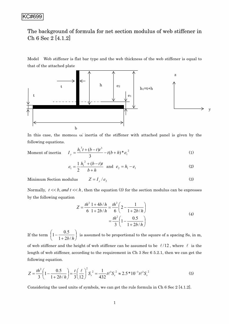
1
The background of formula for net section modulus of web stiffener in Ch 6 Sec 2 [4.1.2]
Model Web stiffener is flat bar type and the web thickness of the web stiffener is equal to that of the attached plate
In this case, the moment of inertia of the stiffener with attached panel is given by the following equations.
Moment of inertia 21
331 *)(
3)( ehbtttbthI y (1)
hbttbhe )(
21 2
11 and 112 ehe (2)
Minimum Section modulus 2/ eIZ y (3)
Normally, htandbt , , then the equation (3) for the section modulus can be expresses
by the following equation
hbth
hbth
hbhbthZ
/215.01
3
/2112
6/21/41
62
22
(4)
If the term hb /21
5.01 is assumed to be proportional to the square of a spacing Ss, in m,
of web stiffener and the height of web stiffener can be assumed to be 12/ , where is the length of web stiffener, according to the requirement in Ch 3 Sec 6 5.2.1, then we can get the following equation.
22323222
10*5.24321
123/215.01
3 sss StStSthb
thZ (5)
Considering the used units of symbols, we can get the rule formula in Ch 6 Sec 2 [4.1.2].
b
hh1=t+h
t
t
z
y
e1
e2
KC#699

��������� ��� ���������
��������������� ������
�������������
������������
KC#727

Case 1:
Case 2:
KC#1074