Bulding 192, Engineering IV, Cal Poly, San Luis Obispo
64
Page 1 of 64 Fire and Life Safety Analysis 3/12/2012 Fire and Life Safety Report Building 192 Engineering IV Cal Poly, San Luis Obispo March 12, 2012 Mark Ferraresi
Transcript of Bulding 192, Engineering IV, Cal Poly, San Luis Obispo

Page 1 of 64 Fire and Life Safety Analysis 3/12/2012
Fire and Life Safety Report
Building 192
Engineering IV
Cal Poly, San Luis Obispo
March 12, 2012
Mark Ferraresi

Page 2 of 64 Fire and Life Safety Analysis 3/12/2012
Table of Contents
1.0 Executive Summary ....................................................................................................................... 4
2.0 References ........................................................................................................................................ 4
3.0 Building Narrative ......................................................................................................................... 4
4.0 Occupancy Classification ............................................................................................................. 5
5.0 Structural Fire Protection and Features ................................................................................ 5
5.1 Building and Construction Materials.................................................................................................. 5
5.2 Construction Type ..................................................................................................................................... 5
5.3 Area and Height Limitations .................................................................................................................. 5
5.4 Fire-Resistive Rated Assemblies .......................................................................................................... 6
5.4.1 Building Structural Elements ........................................................................................................................ 6
5.4.2 Fire and Smoke Partitions .............................................................................................................................. 8
6.0 Means of Egress System ............................................................................................................... 8
6.1 Description of Exits ................................................................................................................................... 8
6.2 Occupancy Loading ................................................................................................................................... 9
6.3 Egress Capacity ........................................................................................................................................ 10
6.4 Number of Exits ....................................................................................................................................... 11
6.5 Arrangement of Exits ............................................................................................................................. 11
6.6 Travel Distance ........................................................................................................................................ 11
6.7 Corridor Fire Resistive Ratings ......................................................................................................... 12
6.8 Exit Signs .................................................................................................................................................... 12
6.9 Interior Finish .......................................................................................................................................... 12
6.10 Special Requirements ......................................................................................................................... 13
7.0 Fire Alarm and Notification System ....................................................................................... 14
7.1 Where Required ...................................................................................................................................... 14
7.2 Type of Fire Alarm System .................................................................................................................. 14
7.3 Fire Alarm Control Panel (FACP) ...................................................................................................... 14
7.4 Detection/Initiating Devices .............................................................................................................. 14
7.4.1 Smoke Detectors............................................................................................................................................... 15
7.4.2 Duct Smoke Detectors .................................................................................................................................... 15
7.4.3 Heat Detectors ................................................................................................................................................... 15
7.4.4 Sprinklers ............................................................................................................................................................ 15
7.4.5 Water Flow Alarm Switches ........................................................................................................................ 15
7.4.6 Manual Pull Stations ....................................................................................................................................... 15
7.5 Notification Appliances ........................................................................................................................ 15
7.5.1 Wall Mounted Strobe ...................................................................................................................................... 15
7.5.2 Wall Mounted Horn Strobe .......................................................................................................................... 16
7.5.3 Water Flow Bell ................................................................................................................................................ 16
7.6 Sequence of Operations (SOO) ........................................................................................................... 16
7.7 Prescriptive-Based Analysis ............................................................................................................... 16
7.7.1 Detection System.............................................................................................................................................. 16
7.7.2 Notification System ......................................................................................................................................... 18
7.7.3 Conclusion ........................................................................................................................................................... 20
8.0 Automatic Sprinkler System .................................................................................................... 21
8.1 Where Required ...................................................................................................................................... 21

Page 3 of 64 Fire and Life Safety Analysis 3/12/2012
8.2 Water Supply Information ................................................................................................................... 21
8.3 Sprinkler System Narrative ................................................................................................................ 22
8.4 Occupancy Hazard Classification ...................................................................................................... 23
8.5 Hydraulic Calculations Verification ................................................................................................. 26
8.5.1 Computer-Based Analysis ............................................................................................................................ 26
8.5.2 Conclusion ........................................................................................................................................................... 26
9.0 Smoke Control System ................................................................................................................ 27
9.1 Where Required ...................................................................................................................................... 27
9.2 Smoke Control Components and Equivalencies .......................................................................... 27
9.2.1 Smoke Curtains ................................................................................................................................................. 27
9.2.2 Third Floor Smoke Barrier ........................................................................................................................... 27
9.2.3 Fire-Resistive Rated Partitions .................................................................................................................. 28
10.0 Performance-Based Analysis ................................................................................................ 28
10.1 Available Safe Egress Time (ASET) and Required Safe Egress Time (RSET) .................. 28
10.2 Available Safe Egress Time (ASET) ................................................................................................ 28
10.2.1 Performance Criteria ................................................................................................................................... 29
10.2.2 Modeling Procedure ..................................................................................................................................... 29
10.2.3 Design Fires ..................................................................................................................................................... 30
10.2.4 Computer Model Results ............................................................................................................................ 35
10.3 Required Safe Egress Time (RSET) ................................................................................................ 36
10.3.1 Detection Time ............................................................................................................................................... 36
10.3.2 Pre-Movement Time .................................................................................................................................... 36
10.3.3 Evacuation Time ............................................................................................................................................ 38
10.3.4 Discussion of Results ................................................................................................................................... 43
10.4 ASET Compared to RSET .................................................................................................................... 44
11.0 Conclusion .................................................................................................................................... 44
Appendix A: Sequence of Operations (SOO) .............................................................................. 45
Appendix B: Occupancy Loading Table Details ........................................................................ 46
Appendix C: Location of Exits .......................................................................................................... 50
Appendix D: Occupancy Classification ......................................................................................... 53
Appendix E: Arrangement of Exits ................................................................................................ 56
Appendix F: Fire-Rated Assembly Locations ............................................................................. 59
Appendix G: Exit Sign Locations ..................................................................................................... 62
Page 4 of 64 Fire and Life Safety Analysis 3/12/2012
1.0 Executive Summary
This report presents a fire and life safety analysis of Engineering IV. This analysis includes a
review of prescriptive code requirements per the International Building Code, 2009 Edition and
other applicable codes and standards; a description of the current fire and life safety systems or
features in place; a prescriptive.based analysis; and a performance.based analysis.
Beyond typical fire protection systems, such as means of egress systems and structural fire
protection, Engineering IV was found to an automatic fire alarm and notification system, an
automatic sprinkler system, and smoke control features. The systems and features surveyed were
found to be within prescriptive compliance. In most cases, prescriptive requirements were not
only met, but exceeded. However, an equivalency was used for smoke control to achieve
compliance.
The performance.based analysis, based on a comparison of ASET and RSET in two fire
scenarios, demonstrated adequate building performance. In both cases, occupants were found to
be able to safely evacuate before untenable conditions were reached.
2.0 References
1. International Building Code, 2009 Edition (IBC)
2. NFPA 13: Standard for the Installation of Sprinkler Systems, 2010 Edition
3. NFPA 72: National Fire Alarm and Signaling Code, 2010 Edition
4. NFPA 101: Life Safety Code, 2009 Edition (LSC)
5. The SFPE Handbook of Fire Protection Engineering, 4th
Edition
6. The NFPA Fire Protection Handbook, 20th
Edition
3.0 Building Narrative
Engineering IV (Building 192) is a three.story building located in the northwest corner of Cal
Poly, San Luis Obispo’s campus core. In plan, the building roughly consists of two wings—one
approximately twice the length of the other—that meet at an obtuse angle. A main corridor
moves along the approximate centerline of the building, flanked by rooms and smaller exit
corridors. In total, the building has a footprint of approximately 42,400 ft2. The floor plan is not
identical amongst all three floors. The square footage for each floor decreases from the first
floor the third floor, and the arrangement and size of rooms changes as well.
The interior architecture of Engineering IV emphasizes an open environment in several corridors
and rooms. The main lobby is an atrium, and is also at the connection point of both building
wings. It is open to all three floors of the building. The building also has several exposed
components, such as structural steel members, plumbing pipes, cable trays, and HVAC ducts.
Most floors in the building are finished concrete, but office spaces are carpeted. The interior
walls are painted gypsum boards that run 15’ from finish floor to ceiling.
There are also several rooms with a suspended ceiling. The ceiling tiles are made of gypsum
board, and are 10’ above finish floor. The rooms with this ceiling are typically computer labs or
Page 5 of 64 Fire and Life Safety Analysis 3/12/2012
faculty and staff offices. Like areas without a suspended ceiling, the flooring is typically
finished concrete, with some areas of carpeting, and the walls are painted gypsum wallboard.
4.0 Occupancy Classification
According to the record drawings, the building was designed per the California Building Code,
2001 Edition, which is based on the UBC. The occupancy type is given as B (business) and A.3
(miscellaneous assembly), which translate to equivalent contemporary IBC classifications of B
and A.3, respectively. The former applies to the classrooms, labs, design studios, and offices
found throughout the building. The latter applies only to these rooms with an expected occupant
load of 50 or greater.
5.0 Structural Fire Protection and Features
This section reviews structural fire protection requirements and features within Engineering IV.
5.1 Building and Construction Materials
Engineering IV is a steel.frame structure. The steel members are exposed in several areas of the
building, including parts of the main corridor and several design labs. The tubular columns are
typically covered by a layer of paint, and wide flange columns are typically surrounded by
gypsum board. The girders and beams are covered with a layer of spray.applied fire.resistive
material (SFRM). Lateral bracing is exposed in several places and is unprotected.
The floor assembly is a concrete slab in unprotected corrugated steel decking. Throughout most
of the building, this concrete slab is exposed, except in faculty and administration offices, where
it is carpeted. The exposed floor also typically acts as the ceiling for most of the building, but
there is a suspended ceiling of gypsum board tiles installed in some computer labs and
throughout the office spaces.
The interior walls appear to be gypsum wallboard attached to steel studs with standard solid.core
doors. The interior walls also have a small quantity of miscellaneous finishes, such as wood
paneling in the atrium. The building exterior is a combination of cement fiberboards, corrugated
metal siding, and insulated glass.
5.2 Construction Type
Record drawings state that Engineering IV is Type II.FR construction type building. Table
19.1.2 from the NFPA Handbook 20th
Edition correlates this to contemporary IBC Type IB and
NFPA Type II (222) buildings.
5.3 Area and Height Limitations
IBC Table 503 lists the allowable building heights and areas for Engineering IV’s occupancy and
construction type, as summarized below:

Page 6 of 64 Fire and Life Safety Analysis 3/12/2012
Summary of IBC Table 503
Group Type I
A B
Height (ft) UL 160
B Stories UL 7
Area UL UL
A-3 Stories UL 5
Area UL UL
= Construction Type of Engineering IV
Since the building is fully sprinklered, the allowable height can be increased by 20’, and the
number of stories by one, per IBC Section 504.2. Additionally, the allowable area can be
increased due to frontage and being fully sprinklered, per Sections 506.2, and 506.3,
respectively. However, these increases would be unnecessary to consider, as IBC Table 503
allows for unlimited area for both B and A.3 occupancies.
Engineering IV has a gross square footage of 104,000 ft2, and each story is approximately 42,400
ft2: well under the allowable area per story. The building also falls under the modified story and
building height limitations, as it is three stories high and approximately 45’ tall. The comparison
between allowable building height, stories, and areas is tabulated below.
Comparison of Engineering IV to Code Requirements Allowable Actual
Height 180 feet 45 feet
Stories 8 (B) and 6 (A-3) 3
Area per Story UL 42,400 sf
5.4 Fire-Resistive Rated Assemblies
Below is a summary of prescriptive requirements and features for fire.resistive rated assemblies
in Engineering IV.
5.4.1 Building Structural Elements
IBC Table 601 provides the required fire.resistance ratings for building elements for all
construction types. The fireproofing providing in Engineering IV meets requirements for Type
IB construction, as shown in the table below:
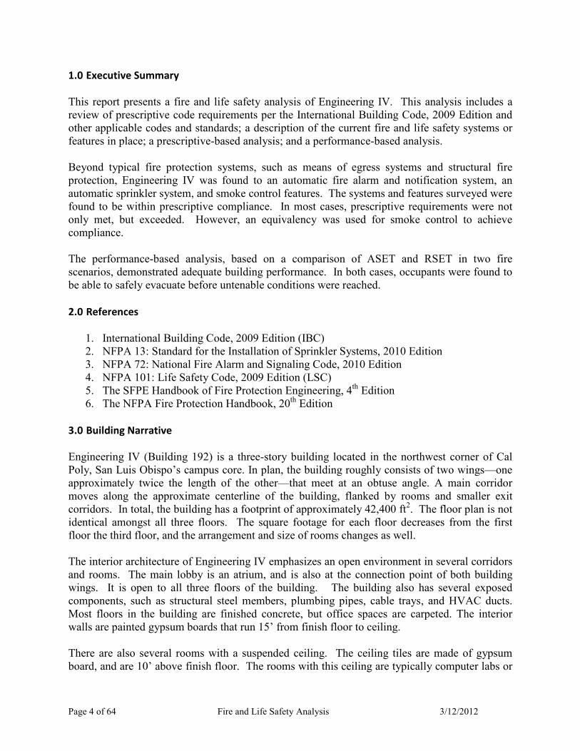
Summary of IBC Table 601 Requirements and Fireproofing Schedule
Building Element Type IB Required
Fire Resistance (hr)
Provided
Fire Resistance (hr)
Primary Structural Frame 2 2
Page 7 of 64 Fire and Life Safety Analysis 3/12/2012
Summary of IBC Table 601 Requirements and Fireproofing Schedule
Building Element Type IB Required
Fire Resistance (hr)
Provided
Fire Resistance (hr)
Bearing Walls
Exterior
Interior
2
2
N/A
N/A
Nonbearing Walls and Partitions
Exterior See Table 602 1
Nonbearing Walls and Partitions
Interior
0
Variable
Floor Construction and Secondary
Members 2 2
Roof Construction and Secondary
Members 1
2½ (Primary Beams)
1½ (Secondary Beams)
1 (Roof Deck)
Engineering IV requires fire.resistance ratings for almost all elements in the building, except for
interior bearing walls. However, since this is a steel structure, all interior walls are nonbearing,
so this requirement is not applicable. The required fire rating for exterior, nonbearing walls and
partitions depends on the occupancy classifications and fire separation distance of nearby
buildings, as outlined in IBC Table 602. Since there are two structures that are between 10’ and
30’ of Engineering IV at its western portion, this table should be consulted, and is summarized
below:
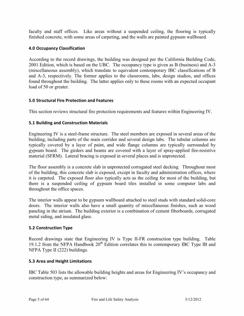
Summary of IBC Table 602 for Fire Separation 10’ ≤ X < 30’
Fire Separation
Distance (feet)
Type of
Construction
Occupancy
Group H
Occupancy
Group F-1,
M, S-1
Occupancy Group
A, B, E, F-2, I, R, S-
2,U
10 ≤ X < 30
IA, IB 2 1 1
IIB, VB 1 0 0
Others 1 1 1
The nearby structures are associated with Cal Poly, and are not Group H occupancies.
Engineering IV is thus required to have only a 1.hour fire.resistance rating for these walls, as
shown in Appendix F: Fire.Rated Assembly Locations.
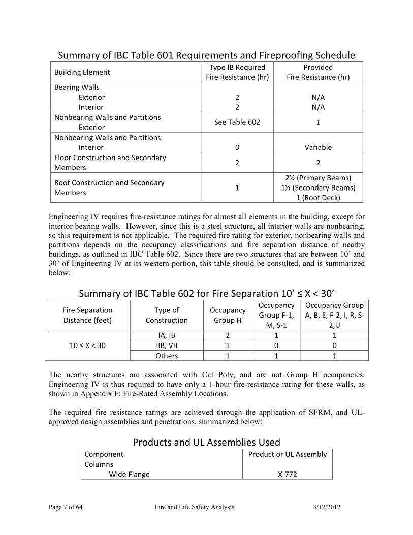
The required fire resistance ratings are achieved through the application of SFRM, and UL.
approved design assemblies and penetrations, summarized below:
Products and UL Assemblies Used Component Product or UL Assembly
Columns
Wide Flange
X-772
Page 8 of 64 Fire and Life Safety Analysis 3/12/2012
Products and UL Assemblies Used Component Product or UL Assembly
Tube X-771
Floor Decks and Roof Decks D-925
Floor and Roof Beams
(Supporting LW Concrete)
N-782
SFRM MK-6/HY
Fire Rated Walls UL U419
Shaft Walls UL U415
Rated Wall Penetrations UL W-L-1054
UL W-L-1067
UL W-L-5029
Rated Floor Penetrations UL C-AJ-1226
5.4.2 Fire and Smoke Partitions
IBC 508.4 requires that A occupancies must be separated from B occupancies by at least a 1.
hour barrier in sprinklered buildings. The locations and ratings of these partitions are shown in
Appendix F: Fire.Rated Assembly Locations.
IBC 709.1 requires corridor wall assemblies to comply with the fire.resistance rating
requirements of IBC 1018.1, as described in 6.7 Corridor Fire Resistive Ratings. The locations
and ratings of these partitions are shown in Appendix F: Fire.Rated Assembly Locations.
Air vents that penetrate these partitions are equipped with combination fire/smoke dampers. The
dampers are static, 1½.hour rated units that close upon fire alarm actuation.
6.0 Means of Egress System
This section describes the means of egress system requirements and features for Engineering IV.
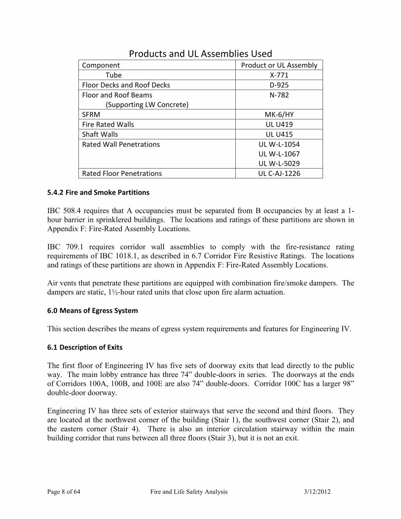
6.1 Description of Exits
The first floor of Engineering IV has five sets of doorway exits that lead directly to the public
way. The main lobby entrance has three 74” double.doors in series. The doorways at the ends
of Corridors 100A, 100B, and 100E are also 74” double.doors. Corridor 100C has a larger 98”
double.door doorway.
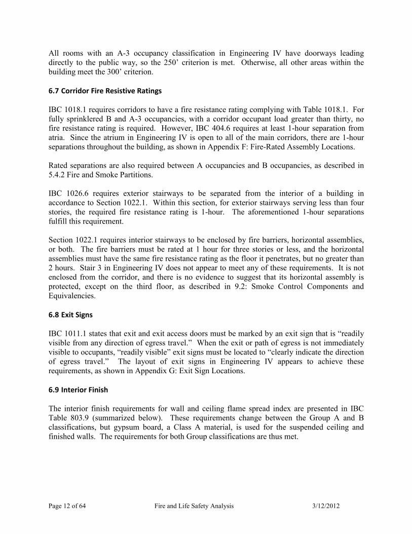
Engineering IV has three sets of exterior stairways that serve the second and third floors. They
are located at the northwest corner of the building (Stair 1), the southwest corner (Stair 2), and
the eastern corner (Stair 4). There is also an interior circulation stairway within the main
building corridor that runs between all three floors (Stair 3), but it is not an exit.

Page 9 of 64 Fire and Life Safety Analysis 3/12/2012
Figure 1: Stair 3, from First Floor
Stairs 1, 2, and 4 are all 66” wide. Stairs 1 and 4 are switchback stairs that run from the ground
level to the third floor. Stair 4 continues to the roof, but a locked gate impedes access to the
roof. Stair 2 is a straight stairway with an intermediate landing that runs from the ground level to
the second floor only. The three doorways leading to the stairways on the second floor are 36”
wide, and the two doorways leading to stairways on the third floor are 39”.
Typically, these doorways lead directly from the corridor to the stairways, except Stair 1 on the
third floor. In this case, the doorway leads to an open.air exterior space with a walkway to the
stairway. The direct line of travel along this open space to the stairway is approximately 28’.
The location of the exits and stairways are shown in Appendix C: Location of Exits.
6.2 Occupancy Loading
The occupant load for Engineering IV was determined using data on record with Cal Poly and
IBC occupant load factors (OLF’s). Cal Poly Facilities Planning and Services’ website
maintains records on both the use and square footage of occupied rooms for all campus
buildings, including Engineering IV. This data was used to provide area values and guide the
selection of OLF’s in calculating occupancy load with two corrections. The use of Room 106—
originally an assembly occupancy—and Room 319—originally a storage occupancy—have both
changed to office occupancies. The OLF’s were retrieved from IBC Table 1004.1.1. The
following OLF’s were used, and were based on a room’s use:
• 50 net for computer, experiment, and instructional labs
• 100 gross for faculty and staff offices
• 300 gross for storage areas and equipment rooms
• 15 net for conference rooms
• 20 net for dedicated classrooms

Page 10 of 64 Fire and Life Safety Analysis 3/12/2012
Using the square footage and OLF’s, the occupant load for Engineering IV is approximately 552
persons for the first floor, 515 for the second, and 331 for the third, or 1398 persons total. The
data, OLF’s, and resultant occupant loads are tabulated on a room.by.room basis in Appendix B:
Occupancy Loading Table Details.
6.3 Egress Capacity
Egress capacity for exits is prescribed in IBC 1005.1. For stairways, 0.3 in/person is permitted,
and 0.2 in/person is permitted for all other exits. In the case of Engineering IV, the latter will
apply to doorways. The exits used to calculate egress capacity are those described in 6.1:
Description of Exits. It should be noted that the egress capacity for exterior stairways not only
depends on the stair width, but also on the width of the doorway leading to the stairway. Thus,
for these exits the lesser egress capacity of the two was used in determining total egress capacity.
Egress capacity comes out to 2,340 persons for the first floor, 540 for the second, and 390 for the
third, or 3,270 persons. On a floor.by.floor basis, the egress capacity is sufficient. The exit
information and resultant egress capacities are tabulated below:
Exit Capacity: First Floor
Exit Width
(in)
Capacity Factor
(in/person)
Capacity
(persons) Notes
Lobby Entrance 222 0.2 1110 3 doors @
74” ea.
Corridor 100A Doorway 74 0.2 370 -
Corridor 100B Doorway 74 0.2 370 -
Corridor 100C Doorway 98 0.2 490 -
Corridor 100E Doorway 74 0.2 370 -
Total: 2340
Required: 552 OK
Exit Capacity: Second Floor
Exit Width
(in)
Capacity Factor
(in/person)
Capacity
(persons) Notes
Stair 1, 36" Doorway 36 0.2 180 Doorway
governs Stair 1 66 0.3 220
Stair 2, 36" Doorway 36 0.2 180 Doorway
governs Stair 2 66 0.3 220
Stair 4, 36" Doorway 36 0.2 180 Doorway
governs Stair 4 66 0.3 220
Total: 540
Required: 515 OK

Page 11 of 64 Fire and Life Safety Analysis 3/12/2012
Exit Capacity: Third Floor
Exit Width
(in)
Capacity Factor
(in/person)
Capacity
(persons) Notes
Stair 1, 39" Doorway 39 0.2 195 Doorway
governs Stair 1 66 0.3 220
Stair 4, 39" Doorway 39 0.2 195 Doorway
governs Stair 4 66 0.3 220
Total: 390
Required: 331 OK
6.4 Number of Exits
Table 1021.1 requires at least 2 exits for story occupant loads less than 500, and 3 exits for story
occupant loads of 501.1,000. The first and second floors of Engineering IV—possessing an
occupant load of 552 and 515, respectively—would require three exits, and the third—having an
occupant load of 331—would require only two. The first floor has 5 separate direct exits, the
second floor has 3 exits, and the third has 2. Every floor thus has the prescribed number of exits.
6.5 Arrangement of Exits
In situations where Table 1021.1 prescribes two exits, IBC 1015.2.1 requires the exits to be
separated by no less than one.half the overall diagonal of the building or area served. However,
this distance can be reduced to one.third of the diagonal because Engineering IV is fully
sprinklered. When more than two exits are prescribed, IBC 1015.2.2 requires at least two of the
exits to be separated by the minimum distance.
The applicable overall diagonals for Engineering IV are 449’, 430’, and 346’ for the first,
second, and third floors, respectively. One.third of these values are 150’, 144’, and 116’.
Drawing these distances on the appropriate floor plan shows that exit arrangement is adequate, as
shown in Appendix E: Arrangement of Exits.
6.6 Travel Distance
The travel distance requirements for Engineering IV are enumerated in Table 1016.1 in IBC
1016.1. The requirements are summarized below:
IBC Table 1016.1 Summary Occupancy Travel Distance With Sprinkler
System (feet)
A 250
B 300
Page 12 of 64 Fire and Life Safety Analysis 3/12/2012
All rooms with an A.3 occupancy classification in Engineering IV have doorways leading
directly to the public way, so the 250’ criterion is met. Otherwise, all other areas within the
building meet the 300’ criterion.
6.7 Corridor Fire Resistive Ratings
IBC 1018.1 requires corridors to have a fire resistance rating complying with Table 1018.1. For
fully sprinklered B and A.3 occupancies, with a corridor occupant load greater than thirty, no
fire resistance rating is required. However, IBC 404.6 requires at least 1.hour separation from
atria. Since the atrium in Engineering IV is open to all of the main corridors, there are 1.hour
separations throughout the building, as shown in Appendix F: Fire.Rated Assembly Locations.
Rated separations are also required between A occupancies and B occupancies, as described in
5.4.2 Fire and Smoke Partitions.
IBC 1026.6 requires exterior stairways to be separated from the interior of a building in
accordance to Section 1022.1. Within this section, for exterior stairways serving less than four
stories, the required fire resistance rating is 1.hour. The aforementioned 1.hour separations
fulfill this requirement.
Section 1022.1 requires interior stairways to be enclosed by fire barriers, horizontal assemblies,
or both. The fire barriers must be rated at 1 hour for three stories or less, and the horizontal
assemblies must have the same fire resistance rating as the floor it penetrates, but no greater than
2 hours. Stair 3 in Engineering IV does not appear to meet any of these requirements. It is not
enclosed from the corridor, and there is no evidence to suggest that its horizontal assembly is
protected, except on the third floor, as described in 9.2: Smoke Control Components and
Equivalencies.
6.8 Exit Signs
IBC 1011.1 states that exit and exit access doors must be marked by an exit sign that is “readily
visible from any direction of egress travel.” When the exit or path of egress is not immediately
visible to occupants, “readily visible” exit signs must be located to “clearly indicate the direction
of egress travel.” The layout of exit signs in Engineering IV appears to achieve these
requirements, as shown in Appendix G: Exit Sign Locations.
6.9 Interior Finish
The interior finish requirements for wall and ceiling flame spread index are presented in IBC
Table 803.9 (summarized below). These requirements change between the Group A and B
classifications, but gypsum board, a Class A material, is used for the suspended ceiling and
finished walls. The requirements for both Group classifications are thus met.

Page 13 of 64 Fire and Life Safety Analysis 3/12/2012
IBC Table 803.9 Summary
Group
Sprinklered
Exit enclosures and
exit passageways Corridors
Rooms and
enclosed spaces
B B C C
A B B C
IBC 804.4.1 details the floor finish requirements for buildings. Since Engineering IV is fully
sprinklered, interior finish in exits and corridors only need to pass the DOC FF.1 “pill test.” All
other spaces within the building need to meet this criterion as well. The majority of finish floor
within Engineering IV is concrete, which is noncombustible. Otherwise, simple synthetic
carpeting is used in some office and administrative areas. The interior floor finish requirements
are satisfied, assuming this carpet material meets the appropriate criterion.
6.10 Special Requirements
Engineering IV features an atrium at the main entrance. The atrium is directly open to the first
two stories, and is also open to the third floor through light wells and Stair 3. IBC 404
enumerates the special requirements for atria, including those in terms of egress.
Figure 2: Engineering IV Atrium, from Main Entrance
IBC 404.5 requires a smoke control system when atria are present in a building, unless it
connects only two stories. This requirement is discussed in more detail in 9.0 Smoke Control
System.

Page 14 of 64 Fire and Life Safety Analysis 3/12/2012
IBC 404.6 requires that atria be separated from adjacent spaces by a 1.hour fire barrier. In
Engineering IV, this is accomplished through the aforementioned 1.hour separations.
IBC 404.8 states that the interior finish of walls and ceilings within the atria must be at least
Class B, or better. Gypsum board is used on the walls and ceiling surrounding the atria, so this
requirement is met.
Finally, IBC 404.9 restricts the travel distance to 200’ for all spaces with exit access through the
atrium, but all the other spaces connected to it only have to conform to the normal requirements
found in IBC 1016.
7.0 Fire Alarm and Notification System
Engineering IV is equipped with an automatic fire alarm and notification system. The
requirements, arrangement, design, and performance of this system are discussed within this
section.
7.1 Where Required
IBC 907.2.1 requires a manual fire alarm system for Group A occupancies with an occupant load
of 300 or more, which none of those in Engineering IV meet. In addition, the alarm system is
not required when an automatic sprinkler system is provided.
IBC 907.2.2 requires a manual fire alarm system for Group B occupancies with a total Group B
occupant load of 500 or more on all floors, which does apply to Engineering IV. However, like
Group A occupancies, an alarm system is not required if an automatic sprinkler system is
provided.
7.2 Type of Fire Alarm System
Engineering IV’s fire alarm and notification systems acts as a proprietary supervising station.
All fault, trouble, and alarm signals are sent to the on.campus University Police Department. In
case of an alarm signal, a runner from the department is sent to verify the presence of fire. Upon
verification, the San Luis Obispo Fire Department is notified and responds accordingly.
7.3 Fire Alarm Control Panel (FACP)
The building is equipped with a Notifier NFS.640 fire alarm control panel. This panel supports
up to 159 detectors and 159 modules and runs an analog system. There are two batteries
attached to the panel as auxiliary power. It is located on the first story, in Room 109, behind a
locked door. According to the fire plan riser diagrams, all detection and initiation devices are
attached directly to the panel.
7.4 Detection/Initiating Devices
Page 15 of 64 Fire and Life Safety Analysis 3/12/2012
Engineering IV is equipped with several types of fire detection and initiating devices. These
include smoke detectors, duct smoke detectors, heat detectors, automatic sprinklers, and manual
pull stations.
7.4.1 Smoke Detectors
The smoke detectors used are Notifier FSP.851 (CSFM #7150.0028:199) models. They are
addressable, analog photoelectric units with a listed spacing of 30’. In total, there are 243 units
throughout the building. They are one of the most used detection devices in the entire building,
and are present in almost every corridor and room.
7.4.2 Duct Smoke Detectors
The duct smoke detectors are Notifier FSD.751P (CSFM #3240.0028.205) models. They are
addressable, photoelectric units with a listed duct air velocity range of 500 to 4,000 ft/min.
There are only two in the building, located near the building roof and connected to the air.
handling units.
7.4.3 Heat Detectors
The heat detectors are Notifier FST.851 (CSFM #7270.0028:196) models. They are
addressable, analog fixed.temperature units with a temperature rating of 135°F. The product
data page does not list an RTI value for the detector. There are only nine units in the building.
7.4.4 Sprinklers
The building is fully sprinklered and has 920 individual sprinklers total. The sprinkler system
and its components are discussed in more detail in 8.0 Automatic Sprinkler System.
7.4.5 Water Flow Alarm Switches
The system has two Potter VSR water flow alarm switches that are connected to the FACP.
They are located in the building’s exterior, at the sprinkler system riser. They are rated to
actuate when a flow of 10 gpm is detected.
7.4.6 Manual Pull Stations
The manual pull stations are Notifier NBG.12LX models. They are addressable, dual.action
units. In total, there are 22 throughout the building, with most located by building exits on the
first story, and the rest located by stairway exits on the second and third stories.
7.5 Notification Appliances
7.5.1 Wall Mounted Strobe
Page 16 of 64 Fire and Life Safety Analysis 3/12/2012
Engineering IV is equipped with 61 wall mounted strobe units. They are System Sensor
S1224MCW models, with candela settings of 15 cd, 15/75 cd, 30 cd, 75 cd, and 110 cd. The
units can run on a 12V or a 24V circuit and still provide the full range of candela settings. Units
set to 15 cd are usually in small corridors, such as those leading to faculty offices in the northeast
corner of the building, as well as the smaller corridors in the western wing. The 75 cd and 110
cd units are in larger rooms and labs, such as the main atrium, and the main corridor. The 30 cd
units are not very common, but can be found in moderate size rooms, such as Room 203, or in
isolated portions of larger rooms, like Room 105.
7.5.2 Wall Mounted Horn Strobe
The building is also equipped with 69 wall mounted horn strobe units. They are System Sensor
P1224MCW models, with the same candela settings as the wall mounted strobe, and have a horn
audibility of 75 dBA at 10’. Again, like the wall.mounted strobe, this unit works on 12V and
24V circuits. Generally, these units can be found in almost every occupied room and spread out
throughout the corridors.
7.5.3 Water Flow Bell
The building is equipped with a water flow bell, located in the southwest corner by the main
sprinkler riser. The unit is a Wheelock MB.G10.24.R. The water flow bell activates as soon as
a sprinkler begins discharging water and induces flow within the riser.
7.6 Sequence of Operations (SOO)
The sequence of operations (SOO) for Engineering IV is provided in the specification for the fire
alarm and notification system. It can be found in Appendix A: Sequence of Operations (SOO).
7.7 Prescriptive-Based Analysis
Below are prescriptive.based analyses of the detection and notification system according to
NFPA 72.2010.
7.7.1 Detection System
7.7.1.1 General
Heat detectors, smoke detectors, and other detection devices follow several general guidelines
and specifications for spacing and location, as laid out in NFPA 72. These requirements include:
• Accessibility to personnel (17.4.2) that allows for regular maintenance (17.4.5)
• Protection from mechanical damage (17.4.3)
• Provide total coverage of the building facilities (17.5), including rooms, closets, enclosed
stairwells, and other building facilities.
Page 17 of 64 Fire and Life Safety Analysis 3/12/2012
The fire alarm system layout seems to follow these specifications. All smoke and heat detectors
are placed on ceilings in the open, and since the ceilings are all 12’ tall or less, they are easily
accessible by ladder. This height also provides physical protection for the units. The plans also
show that there are detectors in each distinct room, closet, and corridor.
7.7.1.2 Smoke Detectors
According to 17.7.3.2.3.1, smoke detectors shall be spaced nominally at 30’ on smooth ceilings
in the absence of specific performance.based criteria. Further, 17.7.3.2.3.5 states that all points
on a ceiling must have a detector within 0.7 times the listed spacing. Most of the ceilings within
this building are finished, and can be considered smooth. However, the main corridor has an
unfinished ceiling, approximately 12’ tall, and has exposed steel members. But the smooth
ceiling assumption can be used because the depth of the members is less than 10% of the ceiling
height, per 17.7.3.2.4.2.
The physical location of detectors is also important. According to 17.7.3.1.1, anticipated plume
and ceiling jet flow paths and any ambient airflows must be taken into consideration. In
Engineering IV, air vents for the HVAC system would need to be accounted for the most. But,
based on a cursory inspection of rooms and the main corridor on the first floor, air vents were
several feet from any detector.
Requirement 17.7.1.8 states that smoke detectors shall not be placed in environments that have a
temperature below 32°F and above 100°F, relative humidity above 93%, and air velocity greater
than 300 ft/min. The Code also stipulates in 17.7.1.9 that smoke detectors should not be placed
in environments that would likely cause nuisance alarms, where there are ambient sources of
smoke, moisture, dust or fumes, and mechanical and electrical influences. This is likely why
there are no smoke detectors in Room 111, a mechanical pump room, and Room 103A, a
welding lab.
The plans make no note of any performance.based criteria. It can be assumed that these units
were placed according to prescriptive design practices. The layout and spacing of the smoke
detectors in the main corridor support this claim, as they are spaced up to 30’ on.center, the
listed spacing for these units. Some rooms, such as Room 130, have spacing up to 30’ as well.
Many smaller rooms, such as the bathrooms, have smaller spacings of 25’ or less. This reduced
spacing is likely caused by the dimensions of the room and the need to satisfy requirement
17.7.3.2.3.5.
There are two locations where smoke detectors are not present. The first is the main atrium. As
described earlier, the atrium is open to the first three stories and is approximately 24’ tall. That
area is only covered by nine sprinklers in a 10’ x 10’ grid. The second is the western corridor on
the second story. There are no smoke detectors because a large HVAC vent runs along the
ceiling in this corridor, and there is no room for a smoke detector to be installed onto the ceiling.
Like the atrium, even though there are no smoke detectors, sprinklers are present, spaced 8’ to
15’ on.center down the length of the corridor.

Page 18 of 64 Fire and Life Safety Analysis 3/12/2012
7.7.1.3 Heat Detectors
Per 17.6.3.1, heat detectors can be spaced in one of two ways on flat, smooth ceilings. The first
way requires detectors to be no further than their listed spacing on.center from another detector,
but they must be within half their listed spacing of walls and partitions, measured out
perpendicularly. The second way is similar to smoke detectors, wherein all points on the ceiling
must be within 0.7 times the listed spacing of a detector.
In this building, there are few heat detectors installed, and most are within rooms with smooth
ceilings. Thus, regulations regarding beam construction (17.6.3.3) and sloped ceilings (17.6.3.4)
do not apply. Some detectors are placed on high ceilings though, per 17.6.3.5. For a typical
ceiling height or 12’ for unfinished ceilings, the heat detector’s listed spacing is reduced to 84%
of its original value (Table 17.6.3.5.1). For the UL listing of 50’, this becomes 42’. Multiplying
this new spacing by 0.7 yields 29’.
Yet, most rooms that heat detectors are installed in are rather small. For example, the elevator
maintenance room, attached to Room 108, is just 8’ x 8’. In fact, the largest room with a heat
detector is Room 111, a mechanical pump room, with the longest distance to the detector being
only 17’.
7.7.2 Notification System
7.7.2.1 Visible Alarm Notification Appliances
NFPA 72, 18.5 and 18.6 discuss the visibility of fire alarm notification systems. The purpose of
visible alarm notification appliances (VANA) is to supplement audible signals and to also
provide notification to hearing.impaired occupants or to areas where audible notification is
impractical. VANA’s may be spaced on a prescriptive basis or performance.based basis.
Per 18.5.4.3.1, prescriptive.based spacing of VANA’s can be satisfied by following both Table
18.5.4.3.1(a) and Figure 18.5.4.3.1, or by following Table 18.5.4.3.1(b). These devices must
also be installed in accordance with Table 18.5.4.3.1(a) or Table 18.5.4.3.1(b) with either a
single visual notification appliance, or two appliances located on opposite walls. Table
18.5.4.3.1(a) gives the maximum allowable room size for wall.mounted visual notification
appliances, with one light per room, two lights per room, and four lights per room. Table
18.5.4.3.1(b) gives the maximum allowable room size for ceiling.mounted visual notification
appliances, with one light at lens heights of 10’, 20’, and 30’.
In Engineering IV, all the VANA’s are wall.mounted, and thus must comply with Table
18.5.4.3.1(a) and Figure 18.5.4.3.1.
As noted earlier, the VANA’s have an adjustable light output or 15 cd, 15/75 cd, 30 cd, 75 cd,
and 110 cd. Most standard size classrooms and design studios—such as Room 329—have a
single 75 cd strobe or 75 cd horn strobe. According to Table 18.5.3.2.1(a), these can adequately
service a 45’ x 45’ room, and these design studios are typically 28’ x 32’: well under the
maximum allowable room dimensions.

Page 19 of 64 Fire and Life Safety Analysis 3/12/2012
Labs and design studios like the Room 136 and Room 131 are larger than the aforementioned
rooms, approximately 32’ x 48’. These are typically equipped with a single 110 cd horn strobe,
which can service a 54’ x 54’ room.
Other rooms in Engineering IV are even larger, and/or have geometry similar to the one
presented in Figure A.18.5.4.3(b). A good example of this type is the Room 102. This room has
a 110 cd strobe unit (allowable for rooms 54’ x 54’) and a 75 cd horn strobe (allowable for
rooms 45’ x 45’), which service 40’ x 40’ and 24’ x 36’ sections of the room, respectively.
The same spacing requirements for rooms may also be used for the placement of VANA’s in
corridors. However, NFPA 72 provides alternate placement and spacing requirements for
corridors. As long as the corridor is 20’ wide or less, 18.5.4.4 allows for VANA’s of no less than
15 cd (per 18.5.4.4.3) to be spaced up to 100’ between units (per 18.5.4.4.5). The units must also
be 15’ or less from the ends of corridors (per 18.5.4.4.5).
The main corridor (Corridor 100C) in Engineering IV is initially 8’ wide at the eastern end of the
building, and tapers out to 20’ as it runs into the main atrium. Other corridors within the
building are typically 8’ wide. As such, the corridors within Engineering IV can follow this
relaxed light output and spacing requirements.
Interestingly, the main corridor seems to forgo the alternate method, as is apparent by the
spacing and light output of notification appliances along its length. On the first story, starting at
the eastern end of the building and ending at the opening of the main atrium, there is a 75 cd
horn strobe, followed by a 110 cd horn strobe 70’ away, followed by a 110 cd strobe 40’ away,
followed by a 110 cd horn strobe 40’ away, followed by 110 cd strobe 48’ away. The units are
much more powerful and closer together than required by code. It is unclear why the designers
choose this course of action, but whatever the case may be, the main corridor is certainly within
NFPA 72 requirements.
Unlike the main corridor, the other smaller corridors generally follow the alternate light output
and spacing requirements. For instance, Corridor 200A has two 15 cd and one 75 cd horn
strobes along its entire 135’ length. Likewise, Corridor 100E has a 15 cd horn strobe and a 15 cd
strobe approximately 36’ apart. For both corridors, there are notification appliances within 15’
of the end of the corridor.
7.7.2.2 Audible Alarm Notification Appliances
NFPA 72, 18.4 discusses the audibility and intelligibility of fire alarm notification systems. At a
minimum, audible alarm notification appliances (AANA’s) within the system must produce an
alarm sound pressure level (SPL) that is 15 dBA above the expected ambient sound level of the
occupied space, or 5 dBA above the loudest SPL that lasts at least 60 seconds (18.4.3.1).
Engineering IV is officially a B and A.3 occupancy, but in day.to.day operations, it functions as
an educational facility. With this in mind, Table A.18.4.3 assigns an ambient SPL of 45 dBA for
such occupancy use. It is unlikely that there will be any sort of long, sustained noises produced
Page 20 of 64 Fire and Life Safety Analysis 3/12/2012
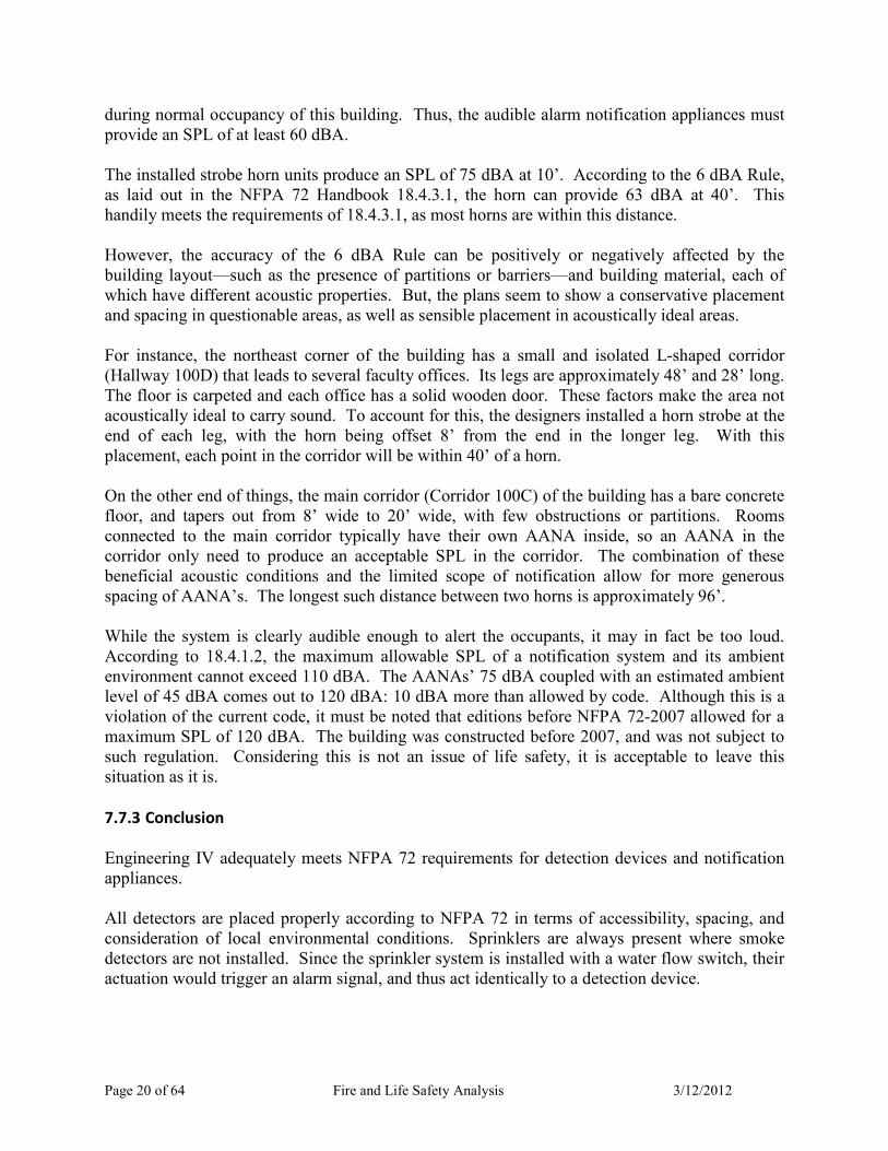
during normal occupancy of this building. Thus, the audible alarm notification appliances must
provide an SPL of at least 60 dBA.
The installed strobe horn units produce an SPL of 75 dBA at 10’. According to the 6 dBA Rule,
as laid out in the NFPA 72 Handbook 18.4.3.1, the horn can provide 63 dBA at 40’. This
handily meets the requirements of 18.4.3.1, as most horns are within this distance.
However, the accuracy of the 6 dBA Rule can be positively or negatively affected by the
building layout—such as the presence of partitions or barriers—and building material, each of
which have different acoustic properties. But, the plans seem to show a conservative placement
and spacing in questionable areas, as well as sensible placement in acoustically ideal areas.
For instance, the northeast corner of the building has a small and isolated L.shaped corridor
(Hallway 100D) that leads to several faculty offices. Its legs are approximately 48’ and 28’ long.
The floor is carpeted and each office has a solid wooden door. These factors make the area not
acoustically ideal to carry sound. To account for this, the designers installed a horn strobe at the
end of each leg, with the horn being offset 8’ from the end in the longer leg. With this
placement, each point in the corridor will be within 40’ of a horn.
On the other end of things, the main corridor (Corridor 100C) of the building has a bare concrete
floor, and tapers out from 8’ wide to 20’ wide, with few obstructions or partitions. Rooms
connected to the main corridor typically have their own AANA inside, so an AANA in the
corridor only need to produce an acceptable SPL in the corridor. The combination of these
beneficial acoustic conditions and the limited scope of notification allow for more generous
spacing of AANA’s. The longest such distance between two horns is approximately 96’.
While the system is clearly audible enough to alert the occupants, it may in fact be too loud.
According to 18.4.1.2, the maximum allowable SPL of a notification system and its ambient
environment cannot exceed 110 dBA. The AANAs’ 75 dBA coupled with an estimated ambient
level of 45 dBA comes out to 120 dBA: 10 dBA more than allowed by code. Although this is a
violation of the current code, it must be noted that editions before NFPA 72.2007 allowed for a
maximum SPL of 120 dBA. The building was constructed before 2007, and was not subject to
such regulation. Considering this is not an issue of life safety, it is acceptable to leave this
situation as it is.
7.7.3 Conclusion
Engineering IV adequately meets NFPA 72 requirements for detection devices and notification
appliances.
All detectors are placed properly according to NFPA 72 in terms of accessibility, spacing, and
consideration of local environmental conditions. Sprinklers are always present where smoke
detectors are not installed. Since the sprinkler system is installed with a water flow switch, their
actuation would trigger an alarm signal, and thus act identically to a detection device.
Page 21 of 64 Fire and Life Safety Analysis 3/12/2012
The AANA’s are positioned and spaced with solid engineering judgment that is both practical
and conservative. There is a potential current code violation, as the combined SPL of the
ambient environment and the alarm may exceed 110 dBA. But, this is not a life safety issue, and
furthermore, this cannot definitively be concluded without on.site sound measurements. The
VANA’s also adequately meet NFPA 72 standards. Strobe selection and placement in rooms
coincides with NFPA requirements, as do strobes located in corridors. No blatant or potential
code violations could be found.
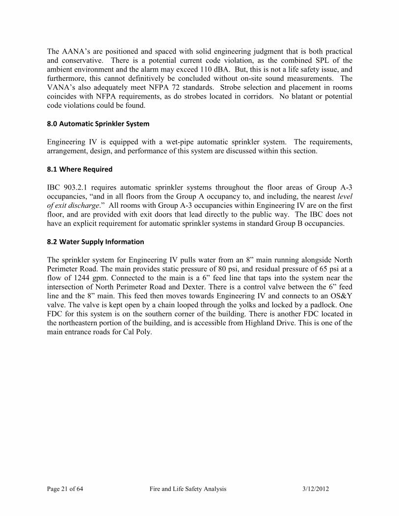
8.0 Automatic Sprinkler System
Engineering IV is equipped with a wet.pipe automatic sprinkler system. The requirements,
arrangement, design, and performance of this system are discussed within this section.
8.1 Where Required
IBC 903.2.1 requires automatic sprinkler systems throughout the floor areas of Group A.3
occupancies, “and in all floors from the Group A occupancy to, and including, the nearest level
of exit discharge.” All rooms with Group A.3 occupancies within Engineering IV are on the first
floor, and are provided with exit doors that lead directly to the public way. The IBC does not
have an explicit requirement for automatic sprinkler systems in standard Group B occupancies.
8.2 Water Supply Information
The sprinkler system for Engineering IV pulls water from an 8” main running alongside North
Perimeter Road. The main provides static pressure of 80 psi, and residual pressure of 65 psi at a
flow of 1244 gpm. Connected to the main is a 6” feed line that taps into the system near the
intersection of North Perimeter Road and Dexter. There is a control valve between the 6” feed
line and the 8” main. This feed then moves towards Engineering IV and connects to an OS&Y
valve. The valve is kept open by a chain looped through the yolks and locked by a padlock. One
FDC for this system is on the southern corner of the building. There is another FDC located in
the northeastern portion of the building, and is accessible from Highland Drive. This is one of the
main entrance roads for Cal Poly.

Page 22 of 64 Fire and Life Safety Analysis 3/12/2012
Figure 3: Water Supply Connection to Engineering IV
8.3 Sprinkler System Narrative
The feed main for the sprinkler system passes through an OS&Y valve, emerges from the ground
just outside Engineering IV, enters the building at about floor lever, and connects to the riser.
The riser then reduces to a 4” pipe, after which, the 4” line splits into two separate 4” pipes. Both
risers then run into building at approximately ceiling height as the cross mains. One of these
cross mains provides water to the first story sprinklers. The second makes it way to a storage
closet (Room 102A) and then rises to the second story. Once there, the 4” cross main splits into
two 4” cross mains. One supplies the second story sprinklers. The other moves to the main
lobby, rises to the third story, and then supplies the sprinkler system there.

Page 23 of 64 Fire and Life Safety Analysis 3/12/2012
Figure 4: Engineering IV Riser Detail
For all floors, the branch lines that run off the cross mains are 1.1/4”. Typically, the sprinklers
are directly attached to the branch lines. However, in some cases, sprinklers are connected to the
branch lines with 1” arm.over lines.
In total, there are 920 individual sprinklers throughout the building. Based on the sprinkler
system shop drawings, it appears that Engineering IV is fully sprinklered and has protection in
every room. Of these 920 sprinklers, there are five distinct types used. Their model, make,
temperature rating, and quantity are as follows:
Summary of Sprinklers Make and Model Temperature Quantity
Reliable F1FR Upright (SIN# 3625) 155°F 242
Reliable F1FR Upright (SIN# 3625) 200°F 28
Reliable G4A Concealed Pendent (SIN# 5415) 155°F 618
Reliable F1FR Horizontal Sidewall (SIN# 3635) 200°F 2
Tyco WS Vertical Pendent (SIN# TY3488) 155°F 30
8.4 Occupancy Hazard Classification
According to the sprinkler shop drawings for Engineering IV, the occupancy class for
Engineering IV switches between Light Hazard (LH) and Ordinary Hazard – Group 1 (OH.1),
depending on the room. For instance, faculty offices fall under the LH occupancy class, and open
labs fall under the OH.1 occupancy class. The calculation design information for the building is

Page 24 of 64 Fire and Life Safety Analysis 3/12/2012
found in the most hydraulically isolated areas of the building, and gives the hazard classification,
the design density, area of operation (with reductions, if applicable), area per head, and hose
stream allowance. System demand information is listed nearby as well, giving required pressure
and flow rate, available pressure, and a safety margin.
For all LH classifications, a design density of 0.10 gpm/ft2 is used, with a 40% reduction of
design area, presumably per NFPA 13.2010, Section 11.2.3.2.3.1 and Figure 11.2.3.2.3.1.
According to Figure 11.2.3.1.1, the design area can thus be reduced to 900 ft2. All LH
classifications have design areas greater than this reduced value due to the non.uniformity in the
building’s layout. The larger areas would create a greater system demand, so this decision could
be considered conservative. All of the above also applies to the OH.1 classified areas, except that
the design density is increased to 0.15 gpm/ft2.
Below are the tables presented in the shop drawings.
Figure 5: 1st Floor, Faculty and Staff Offices
Figure 6: 1st Floor, Open Lab

Page 25 of 64 Fire and Life Safety Analysis 3/12/2012
Figure 7: 2nd Floor, Computer Lab
Figure 8: 2nd Floor, Faculty and Staff Offices
Figure 9: 3rd Floor Offices and Lecture Rooms
Figure 10: 3rd Floor, Biomed Wet Lab

Page 26 of 64 Fire and Life Safety Analysis 3/12/2012
Figure 11: 3rd Floor, Faculty and Staff Offices
8.5 Hydraulic Calculations Verification
A computer.based hydraulic analysis using Elite Fire 6 was performed to verify the sprinkler
system performance. For Engineering IV, there are typically two design areas for each floor. For
this analysis, an OH.1 hazard area on the first floor was used. According to the shop drawings,
the density is 0.15 gpm/ft2, with a design operation of 130 ft
2 per sprinkler head. This
corresponds to a design discharge of 19.5 gpm. The plans also specify schedule 40, threaded
steel pipe. The sprinkler k.factor was found in the corresponding product data sheet provided by
the manufacturer.
8.5.1 Computer-Based Analysis
Nodes were assigned from the bottom of the riser all the way to the hydraulically most distant
sprinkler. The pipe used specified was schedule 40 wet steel. In most cases, the program had
built.in algorithms for fitting losses, such as 90° and 45° elbows. Equivalent lengths from the
previous analysis were used in this analysis when fittings could not be found in the program’s
local database, such as the expansion joint. The equivalent k.factor for sprinklers and arm.overs
was calculated using Elite Fire 6’s built.in calculator.
Using this methodology and assumptions, the system demand was found to be 56.84 psi and
172.53 gpm, respectively. The percent difference between the plan demands is 5.6% and 1.5%.
The solutions obtained in this analysis are close to those used in design. The slight discrepancy
between the two could be caused by a simple calculation or input error, different values for
equivalent lengths, rounding and truncation errors, or any combination thereof.
8.5.2 Conclusion

Page 27 of 64 Fire and Life Safety Analysis 3/12/2012
The automatic sprinkler system meets the hydraulic code requirements by providing adequate
sprinkler density in each design area.
9.0 Smoke Control System
This section describes the smoke control system requirements and features for Engineering IV.
9.1 Where Required
IBC 404.5 requires a smoke control system to be installed according to IBC 909 for atria
connecting three or more floors together. Normally, Engineering IV’s atrium falls under this
category. But measures were taken to avoid providing an active smoke control system, so none
is currently installed.
9.2 Smoke Control Components and Equivalencies
The following smoke control components are present in Engineering IV, apparently as a means
of equivalency permitted per IBC 104.11. These components provide sufficient smoke control,
such that they effectively separate the third floor from the other two. Once separated, the
requirement for a smoke control system in three.story atria no longer applies.
9.2.1 Smoke Curtains
Engineering IV has smoke curtains that activate upon fire alarm actuation. One set of these
curtains is 2.hour horizontal fire shutters that extend across the light wells found in the main
corridors. Another set of curtains drop in front of the doors of Elevator 1 on all three floors.
Figure 12: Light Well Fire Shutters, Opened
9.2.2 Third Floor Smoke Barrier
A small enclosure surrounds the Stair 3 as it enters the third story. The enclosure has large glass
windows and two magnetically activated fire doors. The doors are 90.minute 72” double.doors

Page 28 of 64 Fire and Life Safety Analysis 3/12/2012
equipped with magnetic door holders. The glass windows have 30 horizontal sprinklers aimed
towards them. Upon fire alarm actuation, the magnetic door holders release and allow the doors
to close, creating a sealed barrier. If a fire or sufficient heat reaches the windows, the sprinklers
will activate and spray the windows with water. This will keep them from breaking and
compromising the smoke barrier.
Figure 13: Third Floor Smoke Barrier
9.2.3 Fire-Resistive Rated Partitions
Fire.resistive rated partitions are installed throughout Engineering IV, as described in 5.4.2 Fire
and Smoke Partitions.
10.0 Performance-Based Analysis
A performance.based analysis was performed to determine the adequacy of Engineering IV’s life
safety systems.
10.1 Available Safe Egress Time (ASET) and Required Safe Egress Time (RSET)
The concepts of available safe egress time (ASET) and required safe egress time (RSET) are
commonly used in performance.based design. ASET measures the time it takes for the
environment within a space to become untenable. RSET measures the time needed to safely
egress from said space. If RSET is less than ASET, occupants can safely egress before
conditions become untenable, and vice versa. RSET is typically determined by establishing
tenability (or performance) criteria, creating applicable design fires, and using computer models
to simulate fire effects. ASET is typically determined using case studies, empirical correlations,
computer models, or a combination thereof.
10.2 Available Safe Egress Time (ASET)

Page 29 of 64 Fire and Life Safety Analysis 3/12/2012
For this analysis, two fire scenarios will be considered using the same performance criteria. The
ASET for these two fire scenarios were determined in the following manner.
10.2.1 Performance Criteria
NFPA 101, Section 5.2.2 defines the overall performance criterion as, “Any occupant who is not
intimate with ignition shall not be exposed to instantaneous or cumulative untenable conditions.”
NFPA 101, A.5.2.2 recommends four methods to measure whether this goal is met. Method 2
requires that for each design fire scenario, “the design team can demonstrate that each room or
area will be fully evacuated before the smoke and toxic gas layer in that room descends to a level
lower than 6’ above the floor.” This demonstration will require time estimates for fire detection,
alarm initiation, building evacuation, and smoke layer descent to 6’ above the floor.
10.2.2 Modeling Procedure
Both an FDS and CFAST model will be developed and used to determine ASET for each fire
scenario.
10.2.2.1 FDS Procedure
The FDS model will predict smoke detector and sprinkler activation times, and help visualize the
smoke dynamics and movement. The model will incorporate the relevant local geometry, other
features, and the unmodified, “base” heat release rate (HRR) curve. This HRR curve will be
based on applicable test data for each scenario. In lieu of specific test data, soot yield will be
assumed equal to FDS’s default value of 0.01.
The time to smoke detector activation will be used to determine RSET, as described in 10.3
Required Safe Egress Time (RSET). Smoke detector activation will also be used to activate any
other fire and life safety devices, such as fire shutters, if applicable.
In the event of sprinkler actuation, the HRR curve will be assumed to immediately plateau,
remain constant, and then proceed to follow its decay curve normally once it is reached. This is
a conservative method of accounting for the effect of sprinkler discharge over the fire spread and
growth.
10.2.2.2 CFAST Procedure
The CFAST model will predict the smoke layer height—or upper layer height—through
compartments. Like the FDS model, the CFAST model will use relevant local geometry and
features, but will incorporate the HRR curve modified by sprinkler discharge. The corridors will
be set to CFAST’s default corridor flow characteristics to more accurately simulate smoke
movement.

Page 30 of 64 Fire and Life Safety Analysis 3/12/2012
Figure 14: Schematic of Fire Modeling Procedure
10.2.3 Design Fires
NFPA 101, Section 5.5 provides eight design fire scenarios, one of which that must be used in a
performance.based analysis. Unique features of Engineering IV—such as its open
architecture—should be considered when selecting from these eight scenarios. Additionally,
other scenarios beyond those enumerated by NFPA that present life.safety hazards should be
considered.
10.2.3.1 Design Fire 1 – Light Well Fire
As noted previously, there are light wells connecting all three floors in the main corridor.
Beneath one of these light wells, in front of Room 118, is a tack board on rollers. The tack board
is made of combustible medium density fiberboard (MDF). If this tack board were to ignite,
smoke could potentially travel freely to all three floors, and bypass the building’s smoke control
measures. Such a breach could produce smoke spread throughout Engineering IV.
Figure 15: The Tack Board underneath the Light Well
10.2.3.1.1 Model Design Fire Heat Release Rate Curve
Page 31 of 64 Fire and Life Safety Analysis 3/12/2012
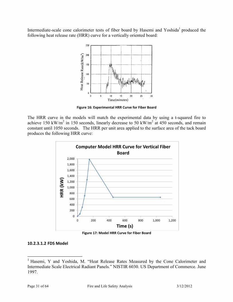
Intermediate.scale cone calorimeter tests of fiber board by Hasemi and Yoshida1 produced the
following heat release rate (HRR) curve for a vertically oriented board:
Figure 16: Experimental HRR Curve for Fiber Board
The HRR curve in the models will match the experimental data by using a t.squared fire to
achieve 150 kW/m2 in 150 seconds, linearly decrease to 50 kW/m
2 at 450 seconds, and remain
constant until 1050 seconds. The HRR per unit area applied to the surface area of the tack board
produces the following HRR curve:
Figure 17: Model HRR Curve for Fiber Board
10.2.3.1.2 FDS Model
1 Hasemi, Y and Yoshida, M. “Heat Release Rates Measured by the Cone Calorimeter and
Intermediate Scale Electrical Radiant Panels.” NISTIR 6030. US Department of Commerce. June
1997.

Page 32 of 64 Fire and Life Safety Analysis 3/12/2012
Sprinklers and smoke detectors were placed 0.10 m below the ceiling in their approximate
location as indicated on as.built drawings. Based on manufacturer’s specifications, the
sprinklers—listed as quick response—were given an RTI of 50 (mOs)1/2
and activation
temperature of 69°C. Similarly, the smoke detectors’ activation obscuration was set to 4.68
%/m, based on the average of the range provided in the manufacturer’s specification. The light
wells were programmed to close upon smoke detector activation.
The fire itself was represented as a planar burner surface. By default, burning only occurs on
one side; in this case the one facing towards Room 118.
Floor plan dimensions were based on as.built drawings. The main corridor, which normally
tapers out as it runs westward, was assumed to be its local minimum dimension.
Figure 18: Design Fire 1 FDS Model
10.2.3.1.3 CFAST Model
The CFAST model incorporated the basic geometry of the primary corridors on each floor. The
corridors on each floor were divided at abrupt changes in corridor width, and connected with
horizontal openings. The width of each corridor was assumed constant, based on the average
width along its entire length.
The three floors were connected with the light wells in front of Room 118 and the openings from
Stair 3. The light wells and fires were contained in a separate compartment on the primary
corridors to ensure the proper alignment of the light wells.
The light wells will be closed at time of smoke detector actuation, based on the results of the
FDS model. The Stair 3 opening between the second and third floor was also programmed to
close upon smoke detector actuation.
10.2.3.2 Design Fire 2 – Room 225 Fire
Page 33 of 64 Fire and Life Safety Analysis 3/12/2012
Although no single NFPA Design Fire Scenario directly correlates to a fire in Room 225, it
would share some important aspects of three. These aspects include:
• It is located near several high.occupancy labs (a part of Scenario 3 and 5)
• It could potentially block the only exit for several building occupants (a part of Scenario
2)
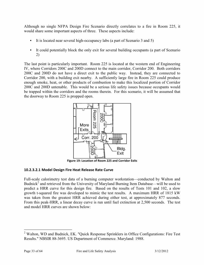
The last point is particularly important. Room 225 is located at the western end of Engineering
IV, where Corridors 200C and 200D connect to the main corridor, Corridor 200. Both corridors
200C and 200D do not have a direct exit to the public way. Instead, they are connected to
Corridor 200, with a building exit nearby. A sufficiently large fire in Room 225 could produce
enough smoke, heat, or other products of combustion to make this localized portion of Corridor
200C and 200D untenable. This would be a serious life safety issues because occupants would
be trapped within the corridors and the rooms therein. For this scenario, it will be assumed that
the doorway to Room 225 is propped open.
Figure 19: Location of Room 225 and Corridor Exits
10.2.3.2.1 Model Design Fire Heat Release Rate Curve
Full.scale calorimetry test data of a burning computer workstation—conducted by Walton and
Budnick2 and retrieved from the University of Maryland Burning Item Database—will be used to
predict a HRR curve for this design fire. Based on the results of Tests 101 and 102, a slow
growth t.squared fire was developed to mimic the test results. A maximum HRR of 1815 kW
was taken from the greatest HRR achieved during either test, at approximately 877 seconds.
From this peak.HRR, a linear decay curve is run until fuel extinction at 2,500 seconds. The test
and model HRR curves are shown below:
2 Walton, WD and Budnick, EK. "Quick Response Sprinklers in Office Configurations: Fire Test
Results." NBSIR 88.3695. US Department of Commerce. Maryland: 1988.

Page 34 of 64 Fire and Life Safety Analysis 3/12/2012
Figure 20: Experimental and Model HRR Curves
10.2.3.2.2 FDS Model
Smoke detectors and sprinklers were placed using the same procedure and methodology as
Design Fire 1. The properties of the devices also matched those used in Design Fire 1.
The fire itself was represented as a 1 m2 burner surface, located halfway between the center of
the room and the doorway to the corridor.
Floor plan dimensions were based on as.built drawings. As in Fire Scenario 1, the main corridor
was assumed to have a uniform width equal to the local minimum. Additionally, thermocouple
trees were placed by the doorways to Corridors 200C and 200D to help measure the descent of
the hot smoke layer.
Figure 21: Design Fire 2 FDS Model
Page 35 of 64 Fire and Life Safety Analysis 3/12/2012
10.2.3.2.3 CFAST Model
The CFAST model incorporated the basic geometry of Room 225, Corridor 200, and Corridor
200A. The width of Corridor 200 was assumed constant, based on the average width along its
entire length.
No openings were considered except for those connecting the three aforementioned
compartments. The light wells that normally connect the separate floors were not included
because it was assumed smoke detector actuation, which closes the smoke shutters in these light
wells, would occur prior to smoke movement to the corridors. The openings at Stair 3 were also
not considered based on the same assumption.
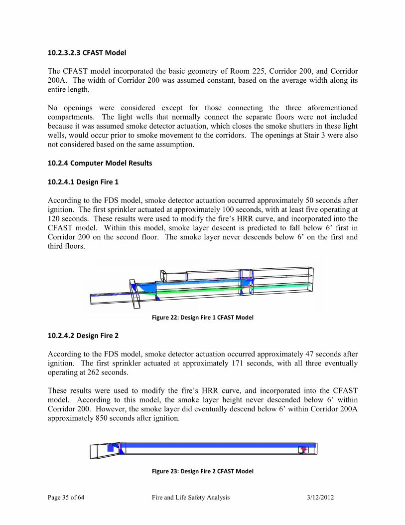
10.2.4 Computer Model Results
10.2.4.1 Design Fire 1
According to the FDS model, smoke detector actuation occurred approximately 50 seconds after
ignition. The first sprinkler actuated at approximately 100 seconds, with at least five operating at
120 seconds. These results were used to modify the fire’s HRR curve, and incorporated into the
CFAST model. Within this model, smoke layer descent is predicted to fall below 6’ first in
Corridor 200 on the second floor. The smoke layer never descends below 6’ on the first and
third floors.
Figure 22: Design Fire 1 CFAST Model
10.2.4.2 Design Fire 2
According to the FDS model, smoke detector actuation occurred approximately 47 seconds after
ignition. The first sprinkler actuated at approximately 171 seconds, with all three eventually
operating at 262 seconds.
These results were used to modify the fire’s HRR curve, and incorporated into the CFAST
model. According to this model, the smoke layer height never descended below 6’ within
Corridor 200. However, the smoke layer did eventually descend below 6’ within Corridor 200A
approximately 850 seconds after ignition.
Figure 23: Design Fire 2 CFAST Model

Page 36 of 64 Fire and Life Safety Analysis 3/12/2012
Summary of Computer Model Results
Scenario #
Smoke
Detector
Activation
Sprinkler
Activation
Smoke Layer
<6’
1 50 sec 100 sec 480 sec
(8 min)
2 47 sec 171 sec 850 sec
(14 min 10 sec)
10.3 Required Safe Egress Time (RSET)
For this analysis, RSET was broken into three general components: detection time, pre.
movement time, and evacuation time. Normally, there are several other time components of
RSET, but they are relatively minor compared the three enumerated, and were therefore not
included.
Detection time is the time from the start of hazard development to recognition of said hazard. In
this situation, the start of hazard development is fire ignition, and recognition is assumed to
occur through Engineering IV’s automatic detection system. This time was determined through
the ASET analysis.
Pre.movement is the series of actions taken by occupants prior to beginning evacuation. This
includes shutting down computers, removing flash drives, finishing phone conversations, or
filing papers. The length of pre.movement time depends on the general behavior and
characterization of occupants (e.g. trained facility workers vs. hotel guests).
Evacuation time is the time it takes for occupants to physically exit to safety. It depends on
travel distance, number of occupants, number of exits, and size of exits.
10.3.1 Detection Time
Detection time was determined in conjunction with the ASET determination, as described in 10.2
Available Safe Egress Time (ASET). The results are shown in 10.2.4 Computer Model Results.
10.3.2 Pre-Movement Time
Engineering IV is located on a college campus, so the majority of occupants will be students,
faculty, and staff. While there can be a wide range of ages within this group, the individuals’
ages should not create an impact on movement time. The students will be almost universally
young, and the faculty and staff will be of non.retirement age. While the latter won’t be as
robust or athletic as the former, they will still be able.bodied and capable of a reasonable egress
speed. This group also does not possess a higher incidence of physical disability compared to
the rest of society. Of course, members of these groups can have physical disabilities that would

Page 37 of 64 Fire and Life Safety Analysis 3/12/2012
retard their movement times, such as wheelchair confinement, but those individuals would be in
the minority.
Pre.movement time will be a more important component of the overall egress time, and will have
more variation amongst occupants in Engineering IV. Of all the occupied spaces within the
building, there are three significant combinations of occupants: faculty and staff only, students
only, and students mixed with faculty and staff. The first combination would mostly occur in
offices, the second in independent study or computer labs, and the third in instructional labs or
classrooms. The significance of these combinations is the presence of faculty and staff. They
are obligated to maintain life safety for all other occupants, especially the students, as an explicit
part of their occupational responsibility. As such, in the event of an alarm they would likely
encourage evacuation of fellow faculty, staff, and students. This is especially true if a faculty
member is currently teaching a class.
Students, on the other hand, have no such explicit mandate, meaning they are less likely to
initiate immediate evacuation individually and amongst themselves without faculty or staff
direction. Students may also be desensitized to fire alarm notification, as most would have
experienced only fire drills in academic settings. As such, there would be little sense of urgency
if an alarm did sound.
Students may also be discouraged from evacuating for fear of appearing alarmist or easily
cowed. According to Chapter 3.11 “Behavioral Response to Fire and Smoke” in the SFPE
Handbook, 4th
Edition, a study showed that students in a room with their peers were far less
likely to leave than if they were alone as smoke slowly entered the room. The students continued
to ignore the smoke to such a point that they began tear up and cough. In Engineering IV,
students will typically be in groups throughout the numerous labs, so this phenomenon is not
unreasonable to expect.
In studies of occupant behavior in office buildings during unannounced drills, occupants were
found to take about 50 seconds before beginning their evacuation. Occupants in these studies
were trained and informed on the building’s evacuation procedure, but “nevertheless spent time
finishing phone calls, saving data on computers, securing files, and gathering belongings before
leaving their desks.”3 As the faculty and staff occupants of Engineering IV are likewise trained
and informed, a similar response is expected.
Student pre.movement time may or may not match this. For the aforementioned reasons,
students are less likely to take a fire alarm seriously and evacuate in a timely manner, unless
given direction by faculty or staff. The pre.movement time may last as long as it takes for a staff
member to find the students and direct them to evacuate, or until the evidence of the fire are
apparent. The inherent uncertainty of these scenarios makes it difficult to assign a universal pre.
movement time. Without any real world data or case studies, the most practical course of action
is to assume ideal student reaction and use 50 seconds.
3 Chapter 3.12: “Evacuation Time”, SFPE Handbook, 4
th Edition

Page 38 of 64 Fire and Life Safety Analysis 3/12/2012
10.3.3 Evacuation Time
Evacuation time was modeled using hand calculations and computer modeling.
10.3.3.1 Hand Calculations
A hydraulic flow model was used to estimate evacuation time for Engineering IV. Within this
model, the following was assumed:
• The flow through the doorways and stairways was based on the maximum possible
specific flow
• The occupant load was distributed equally amongst all primary exit stairways and
doorways
• Travel time to exits was not considered
• The measured path of egress on stairways was taken along the centerline
• The time required to evacuate the first floor was not be considered, as the occupant load
is comparable to the second floor’s load, but has a much larger egress capacity
• The travel time on the stairs was calculated using the longest path of travel from a second
floor exit to the ground level
• Pre.movement time was taken to be 50 seconds, or 0.83 minutes
• Occupants were considered evacuated once they left the exit stairways onto the public
way
The following constants from the NFPA Handbook, 20th
Edition were also used.
Hydraulic Model Constants
Doorway 7 x 11
Stairway
k (ft/min) 275 212
a (ft2/p) 2.86 2.86
Fs,max
(p/min/ft) 24 18.5
Dmax (p/ft2) 0.175 0.175
Total
Boundary
Layer (in)
12 12

Page 39 of 64 Fire and Life Safety Analysis 3/12/2012
Hydraulic Model Constants
Doorway 7 x 11
Stairway
Stairway
Conversion
Factor
- 1.85
The flow rate on the first floor is only governed by doorways, but the flow on the second and
third floors could be governed by the stairways or the doorways that service them. It should be
noted that the second floor doorways are 36” and those on the third floor are 39”. Below are the
calculations for the controlling flow rate for the doorways and stairways:
���36���� = �24�/���/��� × �36�� − 12��� ×��
12��= 48�/���
���39���� = �24�/���/��� × �39�� − 12��� ×��
12��= 54�/���
���66�������� = �18.5�/���/��� × �66�� − 12��� ×��
12��= 83�/���
Based on these results, it is clear that occupants exiting on Stair 2 would be limited by flow
through the doorway. For Stairs 1 and 4, exiting would ultimately be limited by the stairway.
This is because these stairs have occupants exiting from both the second and third floors. Thus,
their combined flow eventually reaches a steady state flow that matches the stairway’s maximum
flow.
10.3.3.1.1 Design Fire 1 – Light Well Fire
In Design Fire 1, it can be assumed that all exits are available, as the fire is not directly blocking
any. Using the predetermined factors, the time to evacuate occupants on Stair 2 is:
��, �36���� =515/3�!����
48�/���= 3.6���
The evacuation time on Stairs 1 and 4 from the second and third floors combined is:
��,"/#�66�������� =515/3�!���� + 331/2�!����
83�/���= 4.1���
Because evacuation of Stairs 1, 2, and 4 occur simultaneously, and the evacuation time for Stair
2 is less than that for Stairs 1 and 4, only the latter evacuation time needs to be considered for
calculating total evacuation time.

Page 40 of 64 Fire and Life Safety Analysis 3/12/2012
The longest path of travel on the stairs from the second floor to ground level is at Stair 4, with a
total distance of 81.6 ft. The travel speed can be estimated thusly:
% = &�1 − �'� = 212�1 − 2.86 × 0.175� = 106��/���
With this velocity, the travel time is calculated to be:
�* =81.6��
106��/���= 0.77���
Taking the detection, pre.movement, exiting, and travel time together, the total evacuation time
is:
� = �+ + �, + ��,"/# + �* = 0.83��� + 0.83��� + 4.1��� + 0.77��� = 6.5���
According to this model, the estimated time to completely evacuate Engineering IV is 6.5
minutes.
10.3.3.1.2 Design Fire 2 – Room 225 Fire
In Design Fire 2, the exit door to Stair 4 on the second floor could be blocked by the fire, as
occupants may be deterred from using it as smoke spills out of Room 225. As such, occupants
on the second floor would be split between Stair 1 and Stair 2.
Using the same procedure as before, the time to evacuate occupants on Stair 2 is:
��, �36���� =515/2�!����
48�/���= 5.4���
The evacuation time on Stairs 1 and 4 from the second and third floors combined is:
��,"/#�66�������� =515/2�!���� + 331/2�!����
83�/���= 5.1���
In this case, Stair 2 is the governing evacuation route.
Taking the pre.movement, exiting, and travel time together, the total evacuation time is:
� = �+ + �, + ��, + �* = 0.78��� + 0.83��� + 5.4��� + 0.77��� = 7.8���
The estimated time to completely evacuate Engineering IV is 7.8 minutes.

Page 41 of 64 Fire and Life Safety Analysis 3/12/2012
Summary of Hand Calculation Results Scenario # Evacuation Time
1 6.5 min
(6 min 30 sec)
2 7.8 min
(7 min 48 sec)
10.3.3.2 Computer Model
In addition to the hand.calculated hydraulic flow model, a computer model—developed using
Pathfinder 2011—was used to estimate total evacuation time. The floor plans for Engineering
IV were replicated by importing DXF files of drawings obtained from Cal Poly Facilities
Planning Services. Rooms were created from these imported floor plans using Pathfinder’s built.
in 3D Extract tool. Occupants were added uniformly to these extracted rooms by assigning an
occupancy density that matched those used previously.
There were slight differences in the occupant load for each floor between previous calculations
and this computer model. In general, the computer model underestimated the number of
occupants, but the difference was relatively minor in all cases. The computer model occupant
loads were not adjusted to match those previously calculated.
Occupancy Load Difference
Floor
Calculated
Occupant
Load
Computer
Model Occupant
Load
% Difference
1 552 535 3.08%
2 515 506 1.75%
3 331 319 3.63%
Doors and stairways were added as needed according to these floor plans. The central
circulation stairway was not included in the computer model because it is not a true building exit
or exit passageway, and thus, is not part of the egress system. Pre.movement times were not
programmed into the computer model. Instead, the 50 seconds used previously were simply
added to its results.

Page 42 of 64 Fire and Life Safety Analysis 3/12/2012
Figure 24: Pathfinder Model of First Floor
Pathfinder features two different “modes” or methods of calculating egress time: steering and
SFPE. Steering is the default mode, and has occupants move individually using a steering
system that maintains a separation distance amongst occupants. SFPE mode maintains a flow
limit at doorways, and occupant velocity is dependent on occupant density. This is essentially
the same methodology used previously for the hand calculations. Both steering and SFPE mode
were used.
10.3.3.2.1 Design Fire 1 – Light Well Fire
Below are the computer model results, with all exits available. For these results, evacuation for a
floor was considered complete once all occupants had entered the exterior stairways. In steering
and SFPE mode, the computer model predicted the evacuation times shown.
Design Fire 1 Computer Model Results
Floor Steering Mode SFPE Mode
1 47 sec -
2 3 min 10 sec 4 min 12 sec
3 1 min 53 sec 2 min 7 sec
In both cases, the second floor was the controlling evacuation time. Taking into account
detection and pre.movement time, the RSET for the second floor would be:
�-*��./01 = �+ + �, + �� = 50� + 50� + 3���10� = 4���50�
�2345 = �+ + �, + �� = 50� + 50� + 4���12� = 5���52�
10.3.3.2.2 Design Fire 2 – Room 225 Fire
Below are the computer model results, with only two exits available on the second floor. For
these results, evacuation for a floor was considered complete once all occupants had entered the
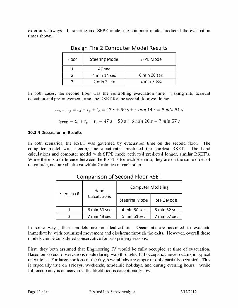
Page 43 of 64 Fire and Life Safety Analysis 3/12/2012
exterior stairways. In steering and SFPE mode, the computer model predicted the evacuation
times shown.
Design Fire 2 Computer Model Results
Floor Steering Mode SFPE Mode
1 47 sec -
2 4 min 14 sec 6 min 20 sec
3 2 min 3 sec 2 min 7 sec
In both cases, the second floor was the controlling evacuation time. Taking into account
detection and pre.movement time, the RSET for the second floor would be:
�-*��./01 = �+ + �, + �� = 47� + 50� + 4���14� = 5���51�
�2345 = �+ + �, + �� = 47�+50s + 6���20� = 7���57�
10.3.4 Discussion of Results
In both scenarios, the RSET was governed by evacuation time on the second floor. The
computer model with steering mode activated predicted the shortest RSET. The hand
calculations and computer model with SFPE mode activated predicted longer, similar RSET’s.
While there is a difference between the RSET’s for each scenario, they are on the same order of
magnitude, and are all almost within 2 minutes of each other.
Comparison of Second Floor RSET
Scenario # Hand
Calculations
Computer Modeling
Steering Mode SFPE Mode
1 6 min 30 sec 4 min 50 sec 5 min 52 sec
2 7 min 48 sec 5 min 51 sec 7 min 57 sec
In some ways, these models are an idealization. Occupants are assumed to evacuate
immediately, with optimized movement and discharge through the exits. However, overall these
models can be considered conservative for two primary reasons.
First, they both assumed that Engineering IV would be fully occupied at time of evacuation.
Based on several observations made during walkthroughs, full occupancy never occurs in typical
operations. For large portions of the day, several labs are empty or only partially occupied. This
is especially true on Fridays, weekends, academic holidays, and during evening hours. While
full occupancy is conceivable, the likelihood is exceptionally low.

Page 44 of 64 Fire and Life Safety Analysis 3/12/2012
Second, neither model considered the effect of Stair 3. Stair 3 was not included because it is not
an exit, as it does not lead directly to the public way and is unprotected. However, in a real fire
event, occupants would not make this distinction, and could potentially use it to evacuate. This
behavior would decrease overall evacuation time by reducing queues at second floor exits.
The combination of these two could significantly reduce RSET for both scenarios.
10.4 ASET Compared to RSET
The largest RSET is less than ASET for both fire scenarios, meaning that occupants can safely
egress prior to untenable conditions first occur. They have a safety factor, or excess time
interval, of 1’30” for Scenario 1 and 6’13” for Scenario 2. Proportionally, ASET is 1.2 and 1.8
times greater than RSET for each scenario, respectively. Both metrics show a distinct separation
between ASET and RSET, even when compared against the largest RSET value, all of which
were conservative.
ASET versus RSET
Scenario
# ASET
RSET (Largest
Result) Safety Factor ASET/RSET
1 8 min 6 min 30 sec 1 min 30 sec 1.2
2 14 min 10 sec 7 min 57 sec 6 min 13 sec 1.8
These results do not mean absolute safety for all potential fire events. Rather, they demonstrate a
reasonable and robust level of performance against the backdrop of two plausible fire events.
11.0 Conclusion
This fire and life safety analysis of Engineering IV reviewed the prescriptive code requirements,
the current life safety systems or features in place, and the adequacy and performance objectives
of said systems, as well as a performance.based analysis. Engineering IV was found to meet the
applicable prescriptive requirements, through typical prescriptive requirements as well as
equivalencies. The performance.based analysis demonstrated a robust performance by
Engineering IV during two separate fire scenarios.
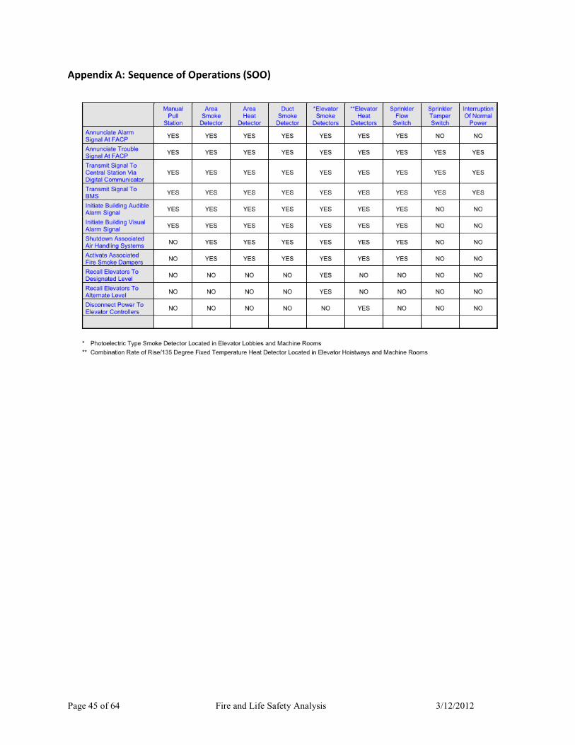
Page 45 of 64 Fire and Life Safety Analysis 3/12/2012
Appendix A: Sequence of Operations (SOO)

Page 46 of 64 Fire and Life Safety Analysis 3/12/2012
Appendix B: Occupancy Loading Table Details
Occupancy Load Calculations: First Floor
Room # Room Type Area
(sf)
OLF
(sf/person)
Load
(persons)
0101-00 Spec Instruction 1790 50 36
0102-00 LwDiv Teach Lab 2693 50 54
0102-A0 Gen Storage 450 300 2
0102-B0 Spec Instruction 308 50 7
0102-C0 Spec Instruction 122 50 3
0103-A0 Tch Lab Serv 415 50 9
0104-00 LwDiv Teach Lab 900 50 18
0105-00 LwDiv Teach Lab 1510 50 31
0105-A0 Tch Lab Serv 630 50 13
0105-B0 Tch Lab Serv 114 50 3
0105-C0 Tch Lab Serv 109 50 3
0106-00 Spec Instruction 3894 100 39
0106-A0 Gen Storage 80 300 1
0115-00 Maint Rpr Sp 503 50 11
0116-00 Grad Teach Lab 1185 50 24
0117-00 Tch Lab Serv 329 50 7
0118-00 Grad Teach Lab 1184 50 24
0119-00 Tch Lab Serv 314 50 7
0120-00 LwDiv Teach Lab 1342 50 27
0121-00 UpDiv Teach Lab 1188 50 24
0122-00 Faculty Office 118 100 2
0123-00 Faculty Office 120 100 2
0124-00 Faculty Office 116 100 2
0125-00 Faculty Office 120 100 2
0126-00 Faculty Office 118 100 2
0127-00 Faculty Office 119 100 2
0128-00 Faculty Office 116 100 2
0129-00 Faculty Office 112 100 2
0129-B0 Gen Storage 14 300 1
0130-00 Spec Instruction 2829 50 57
0131-00 UpDiv Teach Lab 1358 50 28
0132-00 UpDiv Teach Lab 981 50 20
0133-00 Tch Lab Serv 415 50 9
0134-00 LwDiv Teach Lab 1222 50 25

Page 47 of 64 Fire and Life Safety Analysis 3/12/2012
Occupancy Load Calculations: First Floor
Room # Room Type Area
(sf)
OLF
(sf/person)
Load
(persons)
0135-00 UpDiv Teach Lab 1168 50 24
0136-00 UpDiv Teach Lab 1450 50 29
Total: 552
Occupancy Load Calculations: Second Floor
Room # Room Type Area
(sf)
OLF
(sf/person)
Load
(persons)
0201-00 Tch Lab Serv 279 50 6
0202-00 Tch Lab Serv 209 50 5
0203-00 Tch Lab Serv 718 50 15
0204-00 LwDiv Teach Lab 835 50 17
0205-00 LwDiv Teach Lab 1365 50 28
0205-A0 Gen Storage 23 300 1
0206-00 Slf Inst Lab 1100 50 22
0208-00 UpDiv Teach Lab 1870 50 38
0208-A0 Gen Storage 42 300 1
0209-00 UpDiv Teach Lab 1881 50 38
0210-00 Tch Lab Serv 167 50 4
0211-00 Tch Lab Serv 376 50 8
0212-00 LwDiv Teach Lab 640 50 13
0213-00 Gen Storage 131 300 1
0219-00 Maint Rpr Sp 324 50 7
0220-00 UpDiv Teach Lab 2010 50 41
0221-00 LwDiv Teach Lab 1037 50 21
0222-00 Spec Instruction 723 50 15
0223-00 Staff Office 234 100 3
0223-A0 Admin Office 111 100 2
0223-B0 Admin Office 142 100 2
0223-C0 Conf Room 151 15 11
0223-D0 Support Office 175 100 2
0224-00 Lecture 656 20 33
0225-00 Maint Rpr Sp 259 50 6
0226-00 Faculty Office 118 100 2
0227-00 Faculty Office 120 100 2
0228-00 Faculty Office 117 100 2
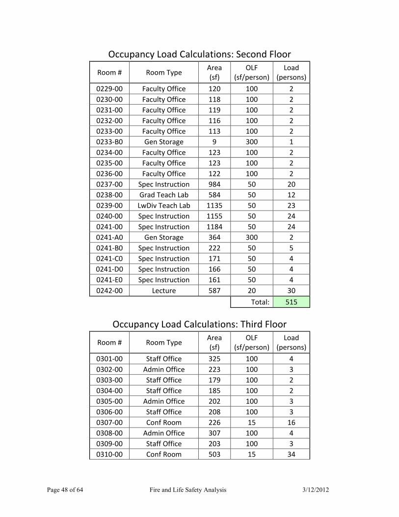
Page 48 of 64 Fire and Life Safety Analysis 3/12/2012
Occupancy Load Calculations: Second Floor
Room # Room Type Area
(sf)
OLF
(sf/person)
Load
(persons)
0229-00 Faculty Office 120 100 2
0230-00 Faculty Office 118 100 2
0231-00 Faculty Office 119 100 2
0232-00 Faculty Office 116 100 2
0233-00 Faculty Office 113 100 2
0233-B0 Gen Storage 9 300 1
0234-00 Faculty Office 123 100 2
0235-00 Faculty Office 123 100 2
0236-00 Faculty Office 122 100 2
0237-00 Spec Instruction 984 50 20
0238-00 Grad Teach Lab 584 50 12
0239-00 LwDiv Teach Lab 1135 50 23
0240-00 Spec Instruction 1155 50 24
0241-00 Spec Instruction 1184 50 24
0241-A0 Gen Storage 364 300 2
0241-B0 Spec Instruction 222 50 5
0241-C0 Spec Instruction 171 50 4
0241-D0 Spec Instruction 166 50 4
0241-E0 Spec Instruction 161 50 4
0242-00 Lecture 587 20 30
Total: 515
Occupancy Load Calculations: Third Floor
Room # Room Type Area
(sf)
OLF
(sf/person)
Load
(persons)
0301-00 Staff Office 325 100 4
0302-00 Admin Office 223 100 3
0303-00 Staff Office 179 100 2
0304-00 Staff Office 185 100 2
0305-00 Admin Office 202 100 3
0306-00 Staff Office 208 100 3
0307-00 Conf Room 226 15 16
0308-00 Admin Office 307 100 4
0309-00 Staff Office 203 100 3
0310-00 Conf Room 503 15 34

Page 49 of 64 Fire and Life Safety Analysis 3/12/2012
Occupancy Load Calculations: Third Floor
Room # Room Type Area
(sf)
OLF
(sf/person)
Load
(persons)
0311-00 Admin Use 169 100 2
0312-00 Admin Use 192 100 2
0313-00 Gen Storage 148 300 1
0319-00 Gen Storage 322 100 4
0320-00 Staff Office 508 100 6
0321-00 LwDiv Teach Lab 1196 50 24
0322-00 LwDiv Teach Lab 1325 50 27
0323-00 UpDiv Teach Lab 1778 50 36
0324-00 Faculty Office 119 100 2
0325-00 Faculty Office 123 100 2
0326-00 Faculty Office 121 100 2
0327-00 UpDiv Teach Lab 1755 50 36
0328-00 UpDiv Teach Lab 877 50 18
0329-00 UpDiv Teach Lab 1130 50 23
0330-00 UpDiv Teach Lab 1110 50 23
0331-00 Lecture 746 20 38
0332-00 Staff Office 241 100 3
0332-A0 Admin Office 172 100 2
0332-B0 Admin Office 170 100 2
0333-00 Admin Use 383 100 4
Total: 331

135136
134
131
132
116118
120 121
130
102
103A
101
106
104
105
133
122
123
124
125
126100D
127128
129
129A
129B110
109
107108
112
111
113
115
114
112A
119117
105A
105B
105C
106A
102A
102B
102C
100
Exit Location - First FloorScale: 1/32" = 1'-0"
Building Exit
Room Exit
Color Key
Lobby Entrance
100E
100C
100B
100A
Page 50 of 64 Fire and Life Safety Analysis 3/12/2012

205
204
203
201
202
205A
206
208
208A
209
210
211
212
213
214
215
200B
216
216A
217
219218
200
242
241E
241D
241C
241 241A
241B
220221 222
239
240
238
237
223D
223
223A 223B
223C
233B
233A
225224
226
227
228
229
230
200C231232
233
234
235
236
200D
200
Exit Location - Second FloorScale: 1/32" = 1'-0"
Building Exit
Room Exit
Color Key
Stair 1
Stair 2
Stair 4
Stair 3
Page 51 of 64 Fire and Life Safety Analysis 3/12/2012
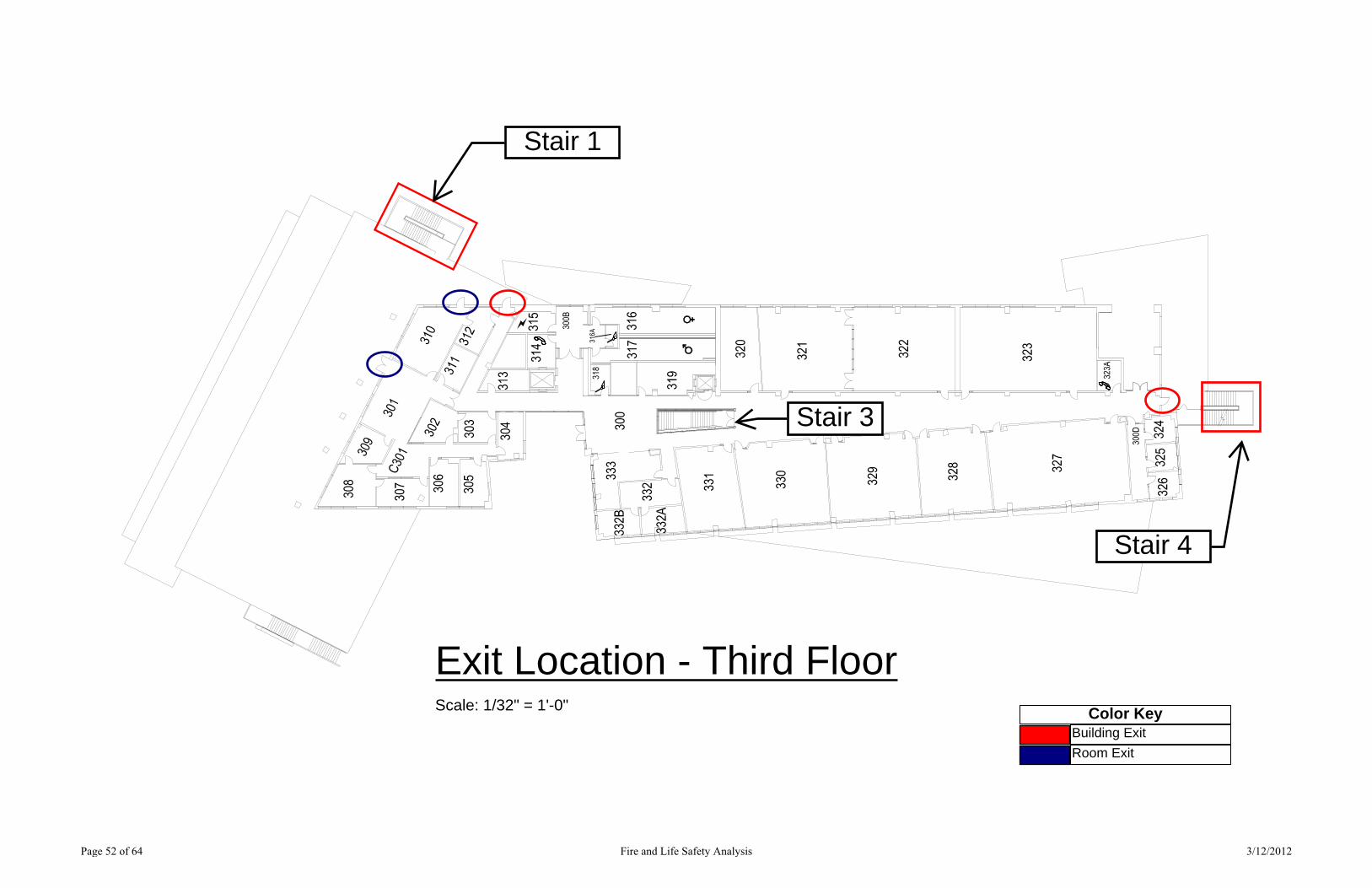
Exit Location - Third FloorScale: 1/32" = 1'-0"
Building Exit
Room Exit
Color Key
Stair 1
Stair 4
Stair 3
Page 52 of 64 Fire and Life Safety Analysis 3/12/2012

135136
134
131
132
116118
120 121
130
102
103A
101
106
104
105
133
122
123
124
125
126100D
127128
129
129A
129B110
109
107108
112
111
113
115
114
112A
119117
105A
105B
105C
106A
102A
102B
102C
100
OccupancyClassifications - First FloorScale: 1/32" = 1'-0"
Business (B) Occupancy
Assembly (A-3) Occupancy
Service Spaces
Exit Access Corridors andPassage Ways
Vertical Exits
Color Key
Page 53 of 64 Fire and Life Safety Analysis 3/12/2012
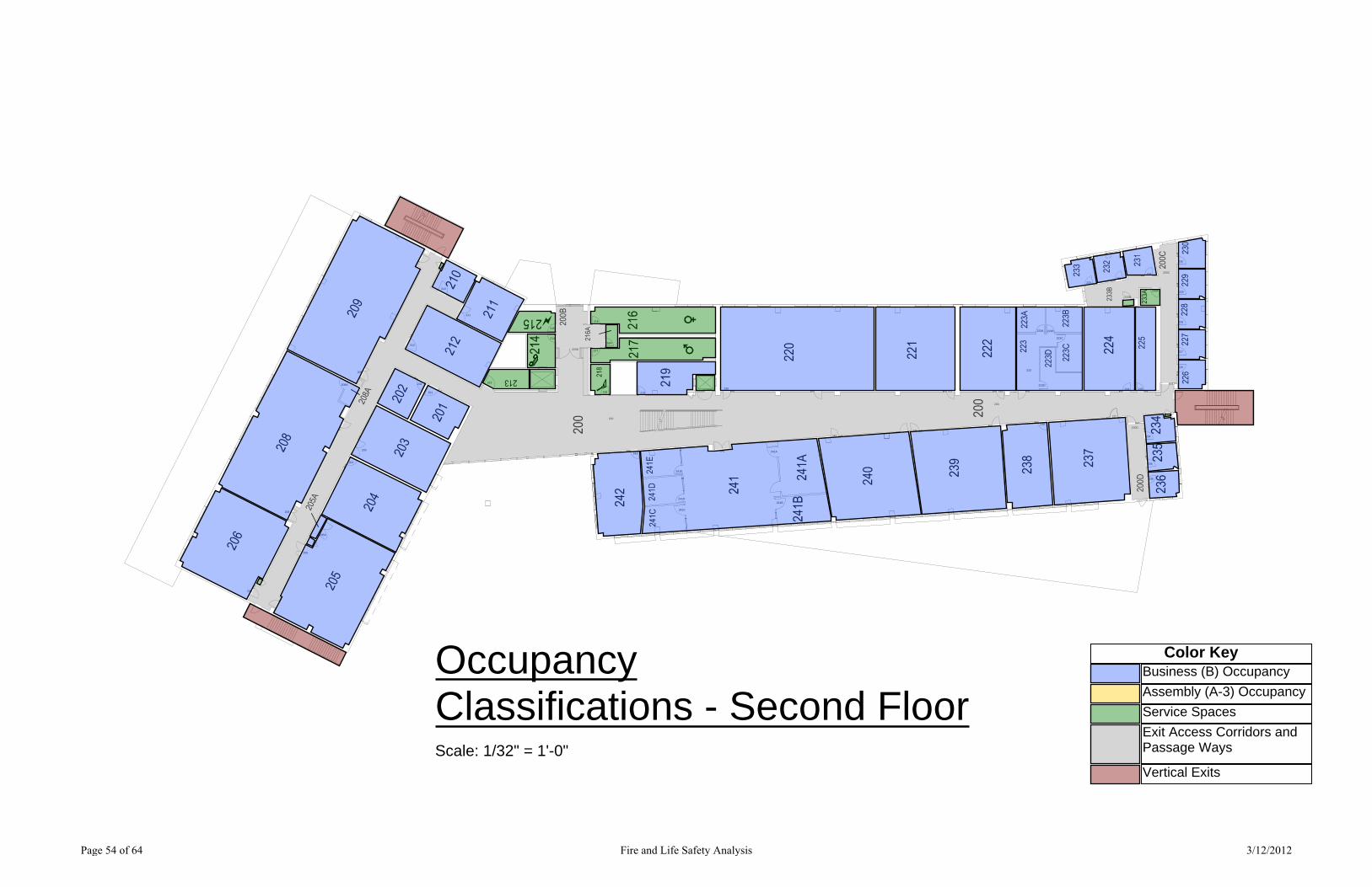
205
204
203
201
202
205A
206
208
208A
209
210
211
212
213
214
215
200B
216
216A
217
219218
200
242
241E
241D
241C
241 241A
241B
220221 222
239
240
238
237
223D
223
223A 223B
223C
233B
233A
225224
226
227
228
229
230
200C231232
233
234
235
236
200D
200
OccupancyClassifications - Second FloorScale: 1/32" = 1'-0"
Business (B) Occupancy
Assembly (A-3) Occupancy
Service Spaces
Exit Access Corridors andPassage Ways
Vertical Exits
Color Key
Page 54 of 64 Fire and Life Safety Analysis 3/12/2012
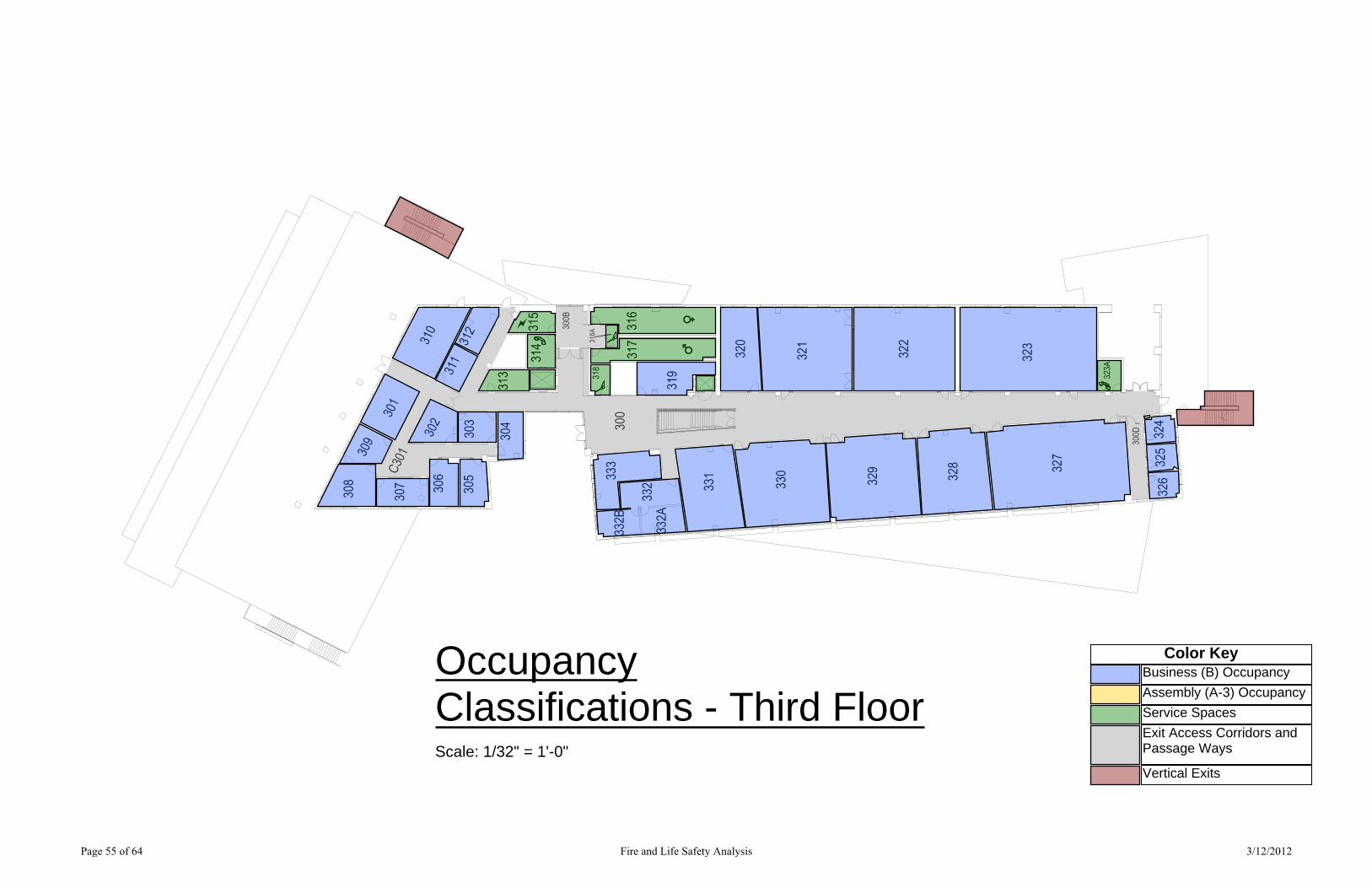
Business (B) Occupancy
Assembly (A-3) Occupancy
Service Spaces
Exit Access Corridors andPassage Ways
Vertical Exits
Color KeyOccupancyClassifications - Third FloorScale: 1/32" = 1'-0"
Page 55 of 64 Fire and Life Safety Analysis 3/12/2012

135136
134
131
132
116118
120 121
130
102
103A
101
106
104
105
133
122
123
124
125
126100D
127128
129
129A
129B110
109
107108
112
111
113
115
114
112A
119117
105A
105B
105C
106A
102A
102B
102C
100
Available Exit
150 ft.
Exit Arrangement - First FloorScale: 1/32" = 1'-0"
Key
Page 56 of 64 Fire and Life Safety Analysis 3/12/2012
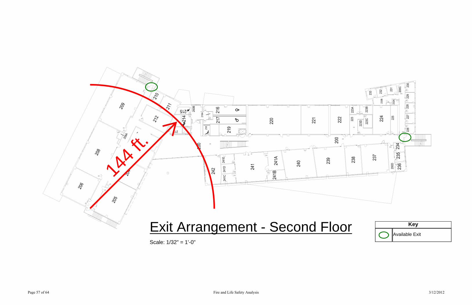
205
204
203
201
202
205A
206
208
208A
209
210
211
212
213
214
215
200B
216
216A
217
219218
200
242
241E
241D
241C
241 241A
241B
220221 222
239
240
238
237
223D
223
223A 223B
223C
233B
233A
225224
226
227
228
229
230
200C231232
233
234
235
236
200D
200
144
ft.
Exit Arrangement - Second FloorScale: 1/32" = 1'-0"
Available Exit
Key
Page 57 of 64 Fire and Life Safety Analysis 3/12/2012
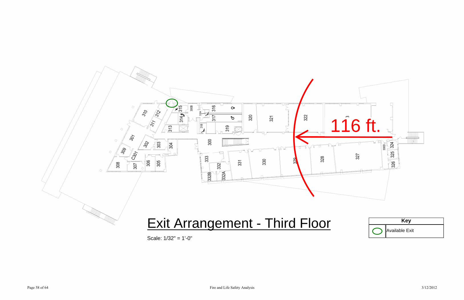
116 ft.
Exit Arrangement - Third FloorScale: 1/32" = 1'-0"
Available Exit
Key
Page 58 of 64 Fire and Life Safety Analysis 3/12/2012

135136
134
131
132
116118
120 121
130
102
103A
101
106
104
105
133
122
123
124
125
126100D
127128
129
129A
129B110
109
107108
112
111
113
115
114
112A
119117
105A
105B
105C
106A
102A
102B
102C
100
1-Hour Separation
2-Hour Separation
Color KeyFire-Rated Assemblies - First FloorScale: 1/32" = 1'-0"
Page 59 of 64 Fire and Life Safety Analysis 3/12/2012
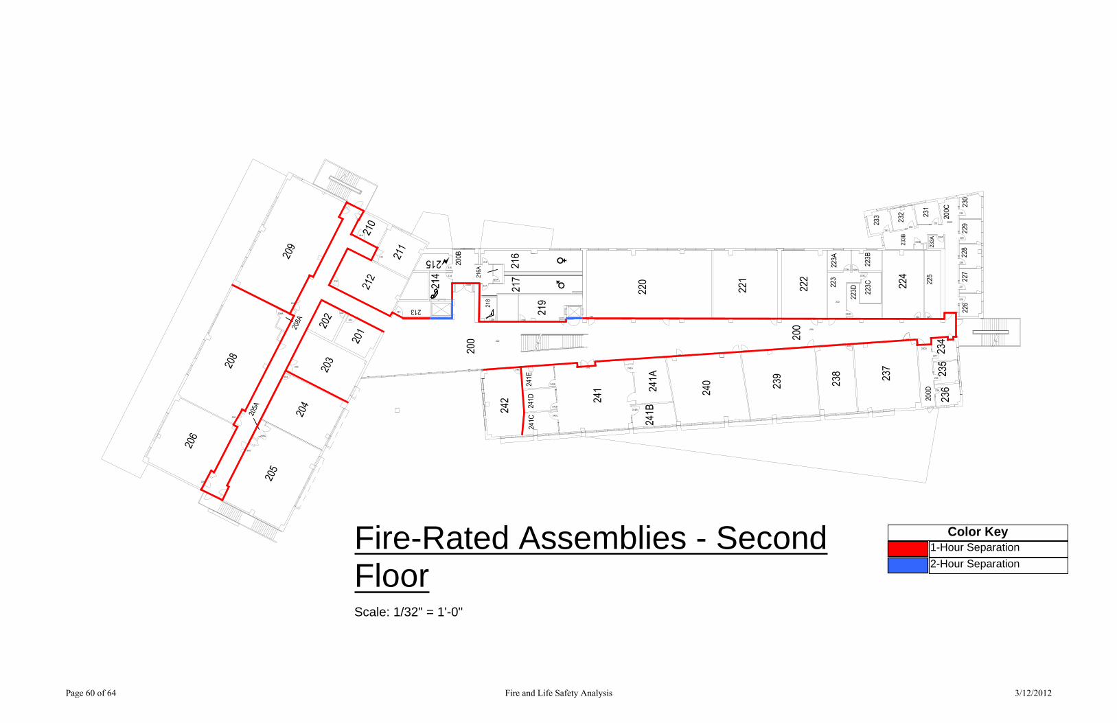
205
204
203
201
202
205A
206
208
208A
209
210
211
212
213
214
215
200B
216
216A
217
219218
200
242
241E
241D
241C
241 241A
241B
220221 222
239
240
238
237
223D
223
223A 223B
223C
233B
233A
225224
226
227
228
229
230
200C231232
233
234
235
236
200D
200
1-Hour Separation
2-Hour Separation
Color KeyFire-Rated Assemblies - SecondFloorScale: 1/32" = 1'-0"
Page 60 of 64 Fire and Life Safety Analysis 3/12/2012

1-Hour Separation
2-Hour Separation
Color KeyFire-Rated Assemblies - Third FloorScale: 1/32" = 1'-0"
Page 61 of 64 Fire and Life Safety Analysis 3/12/2012

135136
134
131
132
116118
120 121
130
102
103A
101
106
104
105
133
122
123
124
125
126100D
127128
129
129A
129B110
109
107108
112
111
113
115
114
112A
119117
105A
105B
105C
106A
102A
102B
102C
100
Exit Sign
Key
Exit Sign Location - First FloorScale: 1/32" = 1'-0"
Page 62 of 64 Fire and Life Safety Analysis 3/12/2012

205
204
203
201
202
205A
206
208
208A
209
210
211
212
213
214
215
200B
216
216A
217
219218
200
242
241E
241D
241C
241 241A
241B
220221 222
239
240
238
237
223D
223
223A 223B
223C
233B
233A
225224
226
227
228
229
230
200C231232
233
234
235
236
200D
200
Exit Sign
Key
Exit Sign Location - Second FloorScale: 1/32" = 1'-0"
Page 63 of 64 Fire and Life Safety Analysis 3/12/2012
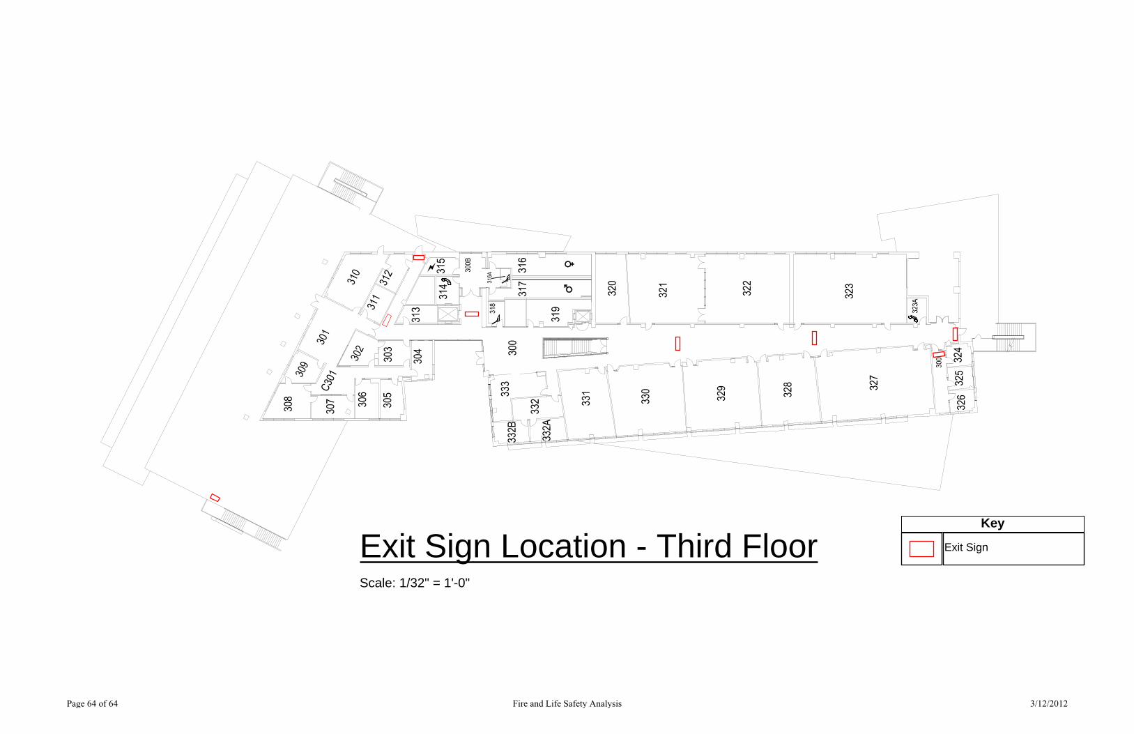
Exit Sign
Key
Exit Sign Location - Third FloorScale: 1/32" = 1'-0"
Page 64 of 64 Fire and Life Safety Analysis 3/12/2012