buildings with load-bearing walls have - RCI,...
9
INTRODUCTION Prior to the 1950s, many buildings were constructed using multi-wythe mass masonry walls. Such walls typically did not include air barriers, weather-resistive barri- ers, vapor retarders, or thermal barriers, as do modern wall assemblies. Buildings consisting of mass masonry are highly dependent on the thickness of their walls and the quality of masonry units and mortar joints within the walls to control water leakage. Over time, such buildings will inevitably exhibit water leakage or will have components that exhibit deteriora- tion due to excess moisture accumulation within the walls. Prior to implementing a repair program to address such issues and to extend the building’s useful life, a systematic condition assessment and water leakage evaluation should be performed. This article describes a methodology for per- forming water leakage evaluations for mass masonry walls. MASONRY WALL TYPES Prior to the 1950s, multi-wythe mass masonry wall systems consisting of solid masonry for their entire thickness were commonly used. Newer and lighter masonry walls were developed after that time. By the 1980s, masonry cavity walls incorporating a water management system were widely used. These walls utilize a drainage cavity, including through-wall fashing and weeps to divert water that penetrates through the single-wythe masonry veneer to the exterior. Ideally, masonry cavity walls are designed and constructed with a weather-resistive barrier installed on the exterior face of the back-up wall to prevent water within the drainage cavity from penetrating further into the wall. Cavity wall construction also typically includes insulation on either the interior or exterior side of the backup wall. Both mass masonry walls and masonry cavity walls rely on the bond between mortar and masonry units to limit water penetra- tion beyond the exterior wythe of the wall or the veneer. Aside from this similarity, mass masonry walls function entirely differently than modern cavity walls. Mass masonry walls rely on their large mass to absorb water that inevitably penetrates beyond the exterior face of the wall. This water is stored within the masonry until it can evaporate to the exterior environment or into the build- ing. Since no insulation was typically used on the interior of the walls, interior paint was highly permeable, and interior spaces were not air-conditioned prior to the mid- 1900s, moisture evaporation to the interior did not typically pose signifcant issues. Additionally, the interior fnish on mass masonry walls was often constructed of cement plaster, which was not susceptible to moisture damage like gypsum plaster. Lack of insulation and the large thermal mass of the masonry also helped keep mass masonry walls relatively warm and reduced temperature fuctuations. Mass masonry walls can be either load-bearing or non-load-bearing. Most buildings with load-bearing walls have been limited to approximately four stories in height, though several such buildings are much taller. Most mid-rise and high- rise buildings included non-load-bearing mass walls constructed with masonry infll between foor slabs. In some instances, the structural concrete frame was exposed to the exterior, with mass masonry infll walls constructed between structural frame ele- ments. In other buildings, the structural frame was completely concealed by the exte- rior wythe of masonry. In these cases, the exterior wythe of masonry was often sup- ported by shelf angles anchored to concrete slab edges. The remaining wythes of mason- ry were typically supported directly on the foor slabs. The confnement of the masonry infll walls by the building frame causes several issues due to differential move- ment between the frame and the masonry. For example, defection of foor slabs that support the masonry can cause cracking. Additionally, the irreversible expansion of the masonry infll can cause stresses to build up within the infll walls, sometimes resulting in bowing. In both load-bearing and non-load-bear- ing masonry mass walls, the individual masonry wythes were typically connected using masonry header courses. WATER PENETRATION THROUGH MASS MASONRY WALLS Mass masonry walls are susceptible to water penetration due to several factors. 10 • I NTERFACE F EBRUARY 2016
Transcript of buildings with load-bearing walls have - RCI,...
INTRODUCTION Prior to the 1950s, many buildings
were constructed using multi-wythe mass masonry walls. Such walls typically did not include air barriers, weather-resistive barri-ers, vapor retarders, or thermal barriers, as do modern wall assemblies. Buildings consisting of mass masonry
are highly dependent on the thickness of their walls and the quality of masonry units and mortar joints within the walls to control water leakage. Over time, such buildings will inevitably exhibit water leakage or will have components that exhibit deteriora-tion due to excess moisture accumulation within the walls. Prior to implementing a repair program to address such issues and to extend the building’s useful life, a systematic condition assessment and water leakage evaluation should be performed. This article describes a methodology for per-forming water leakage evaluations for mass masonry walls.
MASONRY WALL TYPES Prior to the 1950s, multi-wythe mass
masonry wall systems consisting of solid masonry for their entire thickness were commonly used. Newer and lighter masonry walls were developed after that time. By the 1980s, masonry cavity walls incorporating a water management system were widely used. These walls utilize a drainage cavity, including through-wall flashing and weeps to divert water that penetrates through the single-wythe masonry veneer to the exterior.
Ideally, masonry cavity walls are designed and constructed with a weather-resistive barrier installed on the exterior face of the back-up wall to prevent water within the drainage cavity from penetrating further into the wall. Cavity wall construction also typically includes insulation on either the interior or exterior side of the backup wall. Both mass masonry walls and masonry
cavity walls rely on the bond between mortar and masonry units to limit water penetra-tion beyond the exterior wythe of the wall or the veneer. Aside from this similarity, mass masonry walls function entirely differently than modern cavity walls. Mass masonry walls rely on their large mass to absorb water that inevitably penetrates beyond the exterior face of the wall. This water is stored within the masonry until it can evaporate to the exterior environment or into the build-ing. Since no insulation was typically used on the interior of the walls, interior paint was highly permeable, and interior spaces were not air-conditioned prior to the mid-1900s, moisture evaporation to the interior did not typically pose significant issues. Additionally, the interior finish on mass masonry walls was often constructed of cement plaster, which was not susceptible to moisture damage like gypsum plaster. Lack of insulation and the large thermal mass of the masonry also helped keep mass masonry walls relatively warm and reduced temperature fluctuations. Mass masonry walls can be either
load-bearing or non-load-bearing. Most
buildings with load-bearing walls have been limited to approximately four stories in height, though several such buildings are much taller. Most mid-rise and high-rise buildings included non-load-bearing mass walls constructed with masonry infill between floor slabs. In some instances, the structural concrete frame was exposed to the exterior, with mass masonry infill walls constructed between structural frame ele-ments. In other buildings, the structural frame was completely concealed by the exte-rior wythe of masonry. In these cases, the exterior wythe of masonry was often sup-ported by shelf angles anchored to concrete slab edges. The remaining wythes of mason-ry were typically supported directly on the floor slabs. The confinement of the masonry infill walls by the building frame causes several issues due to differential move-ment between the frame and the masonry. For example, deflection of floor slabs that support the masonry can cause cracking. Additionally, the irreversible expansion of the masonry infill can cause stresses to build up within the infill walls, sometimes resulting in bowing. In both load-bearing and non-load-bear-
ing masonry mass walls, the individual masonry wythes were typically connected using masonry header courses.
WATER PENETRATION THROUGH MASS MASONRY WALLS Mass masonry walls are susceptible to
water penetration due to several factors.
1 0 • I n t e r f a c e f e b r u a r y 2 0 1 6

Photo 1 – Open mortar joint between limestone and brick masonry provides
a path for water penetration beyond the exterior wythe of masonry.
Photo 2 – Parapet wall lateral displacement due to inadequate accommodation of irreversible expansion of the brick masonry.
These factors include the following: 1. The condition of mortar joints on the exterior face of the walls greatly impacts the quantity of water that is shed versus that absorbed into the walls. Mortar joints that bond well to masonry units typically serve to reject most of the water that contacts the exterior face of the walls. However, cracked and/or open mortar joints will provide a path for water penetration beyond the exterior wythe of masonry (Photo 1). For several reasons, the mortar and masonry units cannot be made completely watertight.
2. Mass masonry walls were typically not designed with movement joints to accommo-date irreversible expansion of brick masonry, building frame movements, and movements associated with temperature and moisture. Lack of movement joints can result in stress buildup. Such stresses can cause cracking, localized displacement (Photo 2), failure of headers, and/or bowing. The cracks will provide a direct path for water penetration beyond the exterior wythe of masonry.
3. Brick masonry headers were typically used to connect the exterior wythe to the remain-der of the wall. Over time, these headers can fracture due to shear stresses, deterio-ration, or other means. Shear stresses can build up due to differential thermal, frame, or irreversible moisture movements between
f e b r u a r y 2 0 1 6 I n t e r f a c e • 1 1

Photo 3 – Leak location at wall section reduced from four- to two-brick masonry wythes to accommodate internal drain pipe.
Photo 4 – Use of hollow clay tile units
as backup wythes reduces the mass of
masonry that can absorb and retain
moisture.
the exterior wythe and inner wythes. Where headers fail, the exterior wythe of mason-ry can move independently of the interior wythes, typi-cally manifesting as bowing. Cracks in the mortar joints and/or masonry will inev-itably develop due to thismovement, allowing for water penetration beyond the exte-rior wythe.
4. Embedded shelf angles were often constructed without sufficient protection to inhib-it corrosion. As the steel cor-rodes and expands to several times its original size, cracks will develop, allowing water penetration. Steel corrosion can also cause shear stress-es that can lead to failure of brick headers.
5. If the walls are not sufficient-ly thick to provide a large mass to absorb moisture, they can transmit free moisture through their thickness far sooner than more massive walls. In Where portions of walls become less the use of hollow units, such as hol-our experience, walls less than four than four wythes thick at specific low clay tiles, in lieu of solid masonry wythes thick are particularly sus- locations, they will also be more sus- units as backup wythes, reduces the ceptible to occasional water leakage. ceptible to leaks (Photo 3). Similarly, mass of masonry that can absorb
1 2 • I n t e r f a c e f e b r u a r y 2 0 1 6

and retain moisture, thus increasing susceptibility of water leakage (Photo 4).
6. The exterior and interior surfaces of mass masonry walls dry out faster than the center wythe(s) due to their exposure to the environment. As such, thick walls will retain moisture for a long duration, and deterioration of mortar and masonry within the walls is expected (Photo 5). Such deterioration reduces the ability of the walls to absorb and retain additional moisture, leading to more susceptibility to leaks. In many cases, such deterioration goes unnoticed since it is not visible without first removing masonry from the face of the wall.
7. Inadequate workmanship or use of substandard materials during original construction can result in voids within the walls or weak mortar joints that are susceptible to freeze/thaw deterioration. This reduces the ability of the walls to absorb and retain moisture and provides paths through the wall for water pene-tration.
8. Mass masonry walls were typically constructed with cement plaster directly applied to their interior face as a finish. Properly applied, the cement plaster provided for another line of defense against moisture intru-sion. However, more importantly, the cement plaster was not susceptible to degradation when exposed to moisture. Over time, many mass masonry wall
Photo 5 – Deterioration of masonry and mortar within the exterior wall.
www leadingedgesafety net
WE TAKE THE FIRST STEP SO YOU DON T TAKE YOUR LAST
FALL PROTECTION TEMPORARY PERMANENT
f e b r u a r y 2 0 1 6 I n t e r f a c e • 1 3

Photo 6 – Deterioration of interior gypsum-based plaster finishes.
interior finishes have been repaired using gypsum plaster or alternative products such as gypsum sheath-ing. These materials are far more susceptible to degradation due to exposure to moisture. As such, it is not uncommon to encounter mass masonry walls with gypsum-based interior finishes that exhibit ongoing plaster deterioration (Photo 6).
EVALUATING LEAKS IN MASS MASONRY WALLS ASTM E2128, Standard Guide for
Evaluating Water Leakage of Building Walls, describes methods for evaluating causes of water leakage of exterior walls. The recom-mended sequence of activities for an exterior wall leak evaluation program is summarized as follows, with steps listed in parenthesis: 1. Background review (review of proj-ect documents, evaluation of design concept, determination of service history)
2. Field investigation (visual inspec-tion, investigative testing, explorato-ry openings, laboratory testing)
3. Analysis and reporting (analysis, report preparation)
The recommended protocol established by ASTM E2128 can be used as the basis for an exterior wall leak evaluation, regard-less of wall system or material. With specific
1 4 • In t e r f a c e
regard to mass masonry walls, the following items should be considered.
Review of Project Documents Documents that may be helpful for the
investigator include original design docu-ments, codes and standards referenced in the original design documents, submittals, shop drawings, construction photographs and field reports, project closeout doc-uments, and records pertaining to prior repairs. An accurate set of record drawings can
be particularly useful. These documents, taken as a whole, can provide the investiga-tor with a considerably detailed description of the wall construction. Unfortunately, original design docu-
ments for buildings constructed in the late 19th and early 20th centuries usually consisted of only a few sheets of drawings describing the materials and work required for construction. More detailed forms of project documents were not consistently used until after World War II.1
Because document reproduction was once a time-consuming and potentially cost-prohibitive undertaking, only a few copies of the original design documents may have been developed. In many cases, the original design documents may have been misplaced or inadvertently destroyed, and thus unavailable to the investigator. In cases where the original design documents
are available, they may not be legible. In many cases, none of the original construc-tion documents or records related to prior repairs have survived changes in building management and ownership. Nonetheless, investigators should make
every effort to obtain pertinent project docu-ments and glean as much information from them as possible. For most projects, how-ever, the investigator will need to document existing and as-built conditions during a field investigation.
Evaluation of Design Concept Understanding the moisture manage-
ment scheme used for a wall is a crit-ical component of the investigation. Misunderstanding of how the wall system was intended to manage moisture can lead to improper investigation techniques and false conclusions. Mass masonry walls were not designed
with explicit water-resistance performance requirements in mind. Rather, these walls were designed and constructed of sufficient thickness and mass to allow the walls to absorb and store water until it could evapo-rate under favorable conditions. Understanding the structural behavior
of the wall is also important. For load-bear-ing walls, wall thicknesses were typically governed using empirical methods. For non-load-bearing walls, exterior wythes of brick were typically designed to be supported on shelf angles. Details for such systems must provide for the interfacing and integration of components so that each one can perform individually and so that the components can perform collectively as a system.
Determination of Service History Prior to recommending a field inves-
tigation protocol, an investigator should perform a cursory visual evaluation of areas with known leaks, interview building occu-pants and maintenance personnel, and review leak records. Patterns of the report-ed leakage and visible damage will provide hypotheses as to the causes. In some cases, obtaining historic weather records near the building can also be useful. Except under the most severe condi-
tions, leaks through mass masonry wall systems are unlikely to manifest immedi-ately after a rain event. Typically, leaks due to precipitation manifest after long periods of rain, once the walls have become satu-rated. As such, leaks reported shortly after rain commences should be treated with
f e b r u a r y 2 0 1 6

caution. The investigator should consider whether water infiltration could be due to some other mechanism or source (conden-sation, change in interior relative humidity, piping systems, etc.), or through some other building component (fenestration, window perimeter sealant, wall penetrations, roofing system base flashing, etc.). Buildings that exhibit water leakage
may have been previously repaired on one or more occasions. Although well intended, these previous repairs may be contributing to the current leakage. It will be necessary to distinguish between original construction and attempted repairs during subsequent phases of a systematic evaluation.
Visual Inspection The major objectives of a visual inspec-
tion program are to determine as-built condi-tions, document apparent water damage and potential water leakage paths, and formulate hypotheses about the cause(s) of water leak-age. When a visual inspection of the entire building façade is not practical due to access limitations, inspected areas should include both typical and unusual conditions and properly performing and non-performing wall sections. A sufficient number of inspection locations on the interior and exterior of the building must be selected to accomplish these objectives. Other components, such as fenestrations and perimeter sealant around windows and doors, should also be reviewed during this stage. Since project documents for mass
masonry buildings will often not be thor-ough enough to provide the investigator with adequate background information, more inspection locations may be required than are typically needed for newer build-ings. Information lacking in the design documents must be generated from obser-vations, measurements, and exploratory openings in the field. However, such exterior exploratory openings should not typically be made until after investigative testing is performed to allow the wall to be tested in its current “as-found” condition.
Investigative Testing The primary objectives of investigative
testing are to recreate leaks that are known to occur, trace internal leak paths under controlled and reproducible conditions, and correlate test results with observed damage. Regardless of wall type, best practices for investigative testing include the following: 1. For diagnostic purposes, a wall
f e b r u a r y 2 0 1 6
Photo 7 – Calibrated spray rack testing performed on mass masonry wall with adjacent window opening masked to isolate the masonry.
should be tested in its current those that resulted in leaks as close-
2.
3.
4.
as-found condition. Effective diagnostic testing should result in the identification of entry points by isolating adjacent wall components during testing. Where there are windows or other penetra-tions adjacent to the masonry being tested, they must be masked such that deficiencies in adjacent compo-nents or systems cannot contribute to observed water penetration. Those components should also be tested separately by isolating them from the adjacent masonry. Testing of isolated areas should begin at the bottom of the test area and progress vertically to the top. Once testing produces a leak, the entry point and the path followed by the water within and through the wall must be traced.
ly as possible.
While item numbers 1 through 5 above can be readily accomplished during a testing program, replicating the actual conditions under which leakage occurs is not always possible when testing mass masonry walls. Additionally, there are no widely accepted diagnostic test methods that have been specifically developed for evaluating leakage through mass masonry walls. Fortunately, ASTM E2128 allows diagnostic test methods to be adapted from existing test methods and procedures to meet specific objectives for a particular building. Based on our experience, we have found the following test methods appropriate for use when diagnos-ing leaks through mass masonry walls. 1. Calibrated Spray Rack Testing. Procedures similar to those for ASTM E1105, Standard Test Method for Field
5. Interior finishes must be removed Determination of Water Penetration of
6.
in the vicinity of the water testing to readily observe water penetration. However, in the case of interior cement plaster finishes, the remov-al should be limited to the interi-or paint to facilitate observation of wetting patterns. Complete removal of the interior plaster can also yield misleading results. Testing conditions should replicate
Installed Exterior Windows, Skylights, Doors, and Curtain Walls by Uniform or Cyclic Static Air Pressure Difference, can be utilized. This test is performed by wetting a wall area with a matrix of uniformly spaced spray nozzles that deposit a film of water to the wall’s exterior surface, typically at a rate of 5 gallons per square foot per hour (Photo 7).
I n t e r f a c e • 1 7
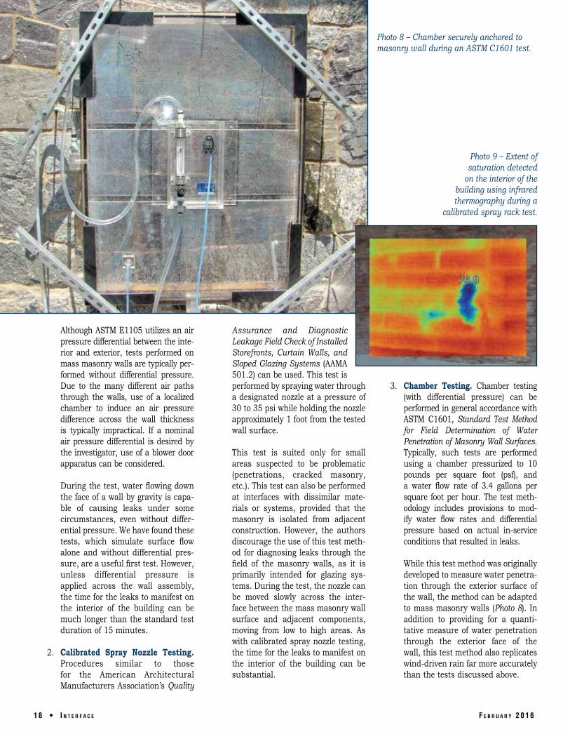
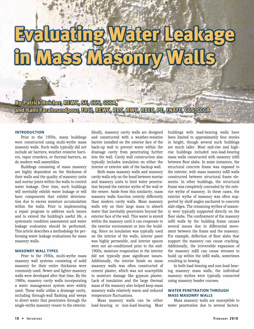
Photo 8 – Chamber securely anchored to masonry wall during an ASTM C1601 test.
Photo 9 – Extent of saturation detected
on the interior of the building using infrared thermography during a
calibrated spray rack test.
Although ASTM E1105 utilizes an air Assurance and Diagnostic pressure differential between the inte- Leakage Field Check of Installed rior and exterior, tests performed on Storefronts, Curtain Walls, and mass masonry walls are typically per- Sloped Glazing Systems (AAMA formed without differential pressure. Due to the many different air paths
501.2) can be used. This test is performed by spraying water through 3. Chamber Testing. Chamber testing
through the walls, use of a localized a designated nozzle at a pressure of (with differential pressure) can be chamber to induce an air pressure 30 to 35 psi while holding the nozzle performed in general accordance with difference across the wall thickness approximately 1 foot from the tested ASTM C1601, Standard Test Method is typically impractical. If a nominal wall surface. for Field Determination of Water air pressure differential is desired by Penetration of Masonry Wall Surfaces. the investigator, use of a blower door This test is suited only for small Typically, such tests are performed apparatus can be considered. areas suspected to be problematic using a chamber pressurized to 10
(penetrations, cracked masonry, pounds per square foot (psf), and During the test, water flowing down etc.). This test can also be performed a water flow rate of 3.4 gallons per the face of a wall by gravity is capa- at interfaces with dissimilar mate- square foot per hour. The test meth-ble of causing leaks under some rials or systems, provided that the odology includes provisions to mod-circumstances, even without differ- masonry is isolated from adjacent ify water flow rates and differential ential pressure. We have found these construction. However, the authors pressure based on actual in-service tests, which simulate surface flow discourage the use of this test meth- conditions that resulted in leaks. alone and without differential pres- od for diagnosing leaks through the sure, are a useful first test. However, field of the masonry walls, as it is While this test method was originally unless differential pressure is primarily intended for glazing sys- developed to measure water penetra-applied across the wall assembly, tems. During the test, the nozzle can tion through the exterior surface of the time for the leaks to manifest on be moved slowly across the inter- the wall, the method can be adapted the interior of the building can be face between the mass masonry wall to mass masonry walls (Photo 8). In much longer than the standard test surface and adjacent components, addition to providing for a quanti-duration of 15 minutes. moving from low to high areas. As tative measure of water penetration
2. Calibrated Spray Nozzle Testing. with calibrated spray nozzle testing, the time for the leaks to manifest on
through the exterior face of the wall, this test method also replicates
Procedures similar to those the interior of the building can be wind-driven rain far more accurately for the American Architectural substantial. than the tests discussed above. Manufacturers Association’s Quality
1 8 • I n t e r f a c e f e b r u a r y 2 0 1 6

The following tools can be used during water testing to assist in interpretation of the results: 1. Infrared thermography can be used
to monitor water penetration and extent of saturation on interior wall surfaces in the vicinity of water test-ing. Surface evaporation at water penetration sites or damp areas results in lower surface tempera-tures that can be detected using an infrared imager (Photo 9).
2. High internal building pressures commonly caused by the mechani-cal systems or stack effect can make it difficult to recreate leaks that occur under wind-driven rain condi-tions. As such, differential air pres-sure measurements should be made during water testing to evaluate con-tributions of internal building pres-sure to interior water leakage. These differential pressure measurements are made using a digital microma-nometer by extending a plastic tube from the micromanometer to the exterior of the building.
In many cases, fenestrations will need to be tested as part of a comprehensive testing program. There are several stan-dard test methods that can used for such purposes. As an example, sill dam tests can be performed in general accordance with AAMA 511. Water testing can also be performed in accordance with ASTM E1105 or AAMA 501.2. Similarly, test methods may be utilized to evaluate the roof mem-brane, base flashing, and/or roof drains if reported leaks are located near the top of the building.
Exploratory Openings Exploratory openings involve the pro-
gressive removal of wall materials to reveal underlying, concealed conditions. Exploratory openings are made to evaluate the extent, sig-nificance, and cause of observed deterioration and hidden deficiencies that may be allowing water leakage into interior areas. A masonry restoration contractor will
typically be required to provide access and to make and temporarily repair exploratory openings. In many cases, the existing origi-nal masonry will be damaged and cannot be
reinstalled. As such, new masonry should be procured prior to the start of the field investigation. The building owner should be forewarned that it may not be possible to match the new masonry to the existing masonry in size, color, and texture. As an example, pre-1950 masonry walls were typically constructed using nonmodular, standard-size units (8 inches wide). Modern brick is typically constructed in modular sizes (75/8 inches wide). It is imperative that the investigator
observe the exploratory opening as it pro-gresses. Sometimes, damage to brick head-ers can result from the removal process. Carefully watching the removal process will help an experienced investigator to evaluate what caused the damage. Exploratory openings also provide for an
opportunity to observe potential water travel paths (Photo 10). In solid masonry walls, dirt deposits within the wall are typical indications of prolonged water travel. When examining fractures, dirt deposits within the fracture plane also help the investigator evaluate if the fracture is fresh (i.e., a result of the removal process) or old.
Building Envelope Technology Symposium
20
16
f e b r u a r y 2 0 1 6 I n t e r f a c e • 1 9

Photo 10 – Staining on backup brick masonry indicates water travel path through wood windowsill into masonry wall.
Material samples can be taken from exploratory openings for subsequent labo-ratory testing.
Laboratory Testing There are numerous laboratory-testing
methods that can be used to evaluate the quality of materials within a solid masonry wall or to assess deterioration mechanisms. A complete review of these test methods is beyond the scope of this article. Some of the most common tests employed
as part of investigating older masonry walls are petrographic examination and chemical testing of mortar materials. These tests pro-vide valuable information regarding mortar constituents and proportions. Such infor-mation is important when specifying repair mortars for repointing or reconstruction of the masonry.
Analysis and Report A comprehensive diagnostic program
should result in an explanation for most, if not all, aspects of the leaks and interior dam-age. The investigator is expected to establish a cause-and-effect relationship between wall characteristics and observed leakage.
2 0 • I n t e r f a c e
It is imperative that conclusions are made based solely on the facts and that false conclu-sions are not made. Unfortunately, for mass masonry wall systems, it may not always
Patrick Reicher is a senior struc-tural engineer with Building Technology Con-sultants, PC, a forensic engi-neering firm in Arlington Heights, Illinois. Reicher is a licensed struc-tural engineer in the State of Illinois and has over 10
years of specialized experience in the eval-uation and repair design of many types of buildings, from recently constructed to historic structures. He is also a Registered Exterior Wall Consultant (REWC), Certified Construction Specifier (CCS), and Certified Construction Contract Administrator (CCCA).
Patrick Reicher,REWC, SE, CCS, CCCA
be possible to extrapolate field investigation findings to the remainder of the building without performing an all-encompassing and likely cost-prohibitive field investigation. Such limitations and disclaimers must be clearly enumerated. The report can also include recommendations for additional investigation and/or recommendations for repair.
SUMMARY Evaluating water leakage issues in mass
masonry walls should start with an under-standing of their water management char-acteristics. Due to limited or nonexistent docu-
mentation of original construction, lack of obviously clear leakage paths, and poten-tially insufficient industry standards for guidance, evaluation of mass masonry exte-rior walls for water leakage can seem like a daunting task. However, experienced inves-tigators can develop exterior wall evaluation protocols specifically for mass masonry walls by following the methodology outlined in ASTM E2128. Results obtained from a well-implemented program can then be used as the basis for repair design.
REFERENCES 1. The Construction Specification Institute (CSI) was formed in 1948, in part to address the growing need in the design and construction industries for a standard approach to project documentation.
Kami Farahmand-pour is the prin-cipal of Building T e c h n o l o g y Consultants, PC, a forensic engineer-ing firm in Arlington Heights, Illinois. Farahmandpour has been involved in the evaluation, testing, and repair of construction materials and building envelope performance since
1984. Kami is a Fellow of RCI, Inc., and a Fellow of the National Academy of Forensic Engineers. He has served as an expert on several cases involving defects in construc-tion, design, and maintenance of building envelope systems.
f e b r u a r y 2 0 1 6
Kami Farahmandpour,FRCI, REWC, RRC,RTWC, RBEC, PE,FNAFE, CCS, CCCA