Oracle ADF Architecture TV - Design - ADF Architectural Patterns

1 Building the Opencockpits ADF Radio
www.kennair.com.au | 2009
With this tutorial I hope to partly address the lack of adequate instruction available for
assembly of the Opencockpits radios. This is a shame as the Opencockpits hardware and
software offer some of the best value for the home cockpit builder on a budget. There
are a number of websites that proved invaluable to my knowledge and understanding of
Opencockpits hardware and software and I would highly recommend researching these
sites prior to undertaking this build. You’ll find a full list at the end of this document.
This tutorial assumes that the user already owns the Opencockpits Mastercard as the
associated 7-segment Display cards need to connect to this unit in order to operate. You
should also have an understanding of the software SIOC which is used to program the
different functions of the radios. A sample file is included in the Appendix.
The ADF panel comprises a front plate laser
cut and ready for backlighting, backplate,
switch mounting plate and TFR button.
In addition you will need the following to
complete the radio:
1 x OMROM B3F 4050 keyswitches
2 x ON-OFF toggle switches
10 x 7-segment display digits
1 x CTS288 rotary encoder
2 x PCB’s for 5 digit display
1 x Gray knob
1x Opencockpits Display Card
Lots of multipin plugs and cables
NOTE: The 7-segment displays need to be the Common Cathode variety and all are
available from the Opencockpits Shop
Other options you might consider are:
Dual concentric rotary encoder or alternatively use two rotary encoders to
achieve High & Low digit selection (this is what I did).
3mm White LED’s for backlighting. (Installation details at the end of this
document)
The Transfer button comes in two pieces. Simply
glue the black button onto the clear base with
superglue. The backing plate is clear to allow light
through when backlit.

2 Building the Opencockpits ADF Radio
www.kennair.com.au | 2009
Here's the result. It will only take a few minutes
using superglue. Edges need to be painted black to
avoid light leakage when backlit. Use acrylic paint
available from any craft shop.
Then some sort of pins need to be installed that will
push on the switch mounted above it. I used plastic
knitting needles cut to size and glued in place. Be
sure to get the length correct. The pointed ends
insert into the small hole in the Omron momentary
switch for button centering.
Buttons fit into the backplate and 25mm threaded
standoff shafts hold the frontplate to the back and the
switches above the buttons as can be seen in the next
photo.
These photos show the COMM panel but the principle is
the same.
Glue the Omron switches onto the clear mounting plate
and align with the needle ends.
3 Building the Opencockpits ADF Radio
www.kennair.com.au | 2009
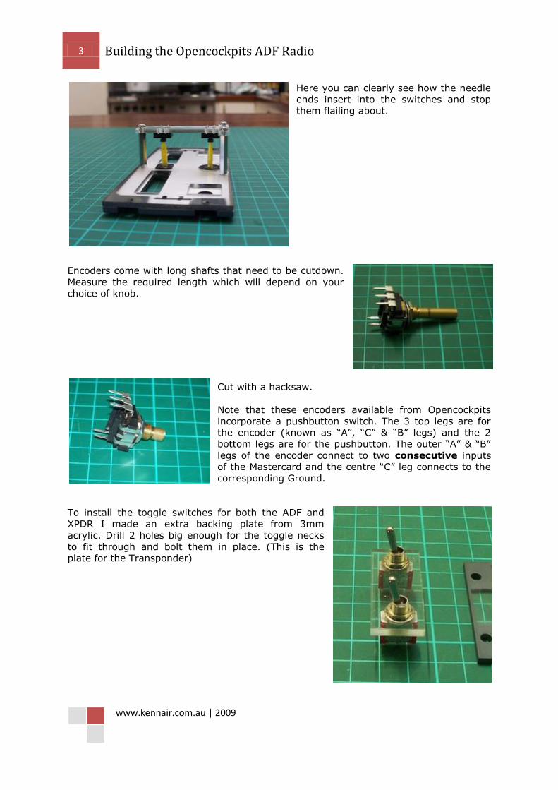
Here you can clearly see how the needle
ends insert into the switches and stop
them flailing about.
Encoders come with long shafts that need to be cutdown.
Measure the required length which will depend on your
choice of knob.
Cut with a hacksaw.
Note that these encoders available from Opencockpits
incorporate a pushbutton switch. The 3 top legs are for
the encoder (known as “A”, “C” & “B” legs) and the 2
bottom legs are for the pushbutton. The outer “A” & “B”
legs of the encoder connect to two consecutive inputs
of the Mastercard and the centre “C” leg connects to the
corresponding Ground.
To install the toggle switches for both the ADF and
XPDR I made an extra backing plate from 3mm
acrylic. Drill 2 holes big enough for the toggle necks
to fit through and bolt them in place. (This is the
plate for the Transponder)
4 Building the Opencockpits ADF Radio
www.kennair.com.au | 2009
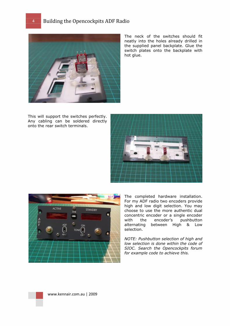
The neck of the switches should fit
neatly into the holes already drilled in
the supplied panel backplate. Glue the
switch plates onto the backplate with
hot glue.
This will support the switches perfectly.
Any cabling can be soldered directly
onto the rear switch terminals.
The completed hardware installation.
For my ADF radio two encoders provide
high and low digit selection. You may
choose to use the more authentic dual
concentric encoder or a single encoder
with the encoder’s pushbutton
alternating between High & Low
selection.
NOTE: Pushbutton selection of high and
low selection is done within the code of
SIOC. Search the Opencockpits forum
for example code to achieve this.

5 Building the Opencockpits ADF Radio
www.kennair.com.au | 2009
Now onto the heart of the
system, the displays board.
The Opencockpits display
board controls up to 16 x
7-segment displays
connected as shown in this
diagram. The displays PCB
caters for all the associated
connections to the card via
multipin cables that you will
need to make.
More on that later.
As you can see from the picture above,
the 7-segments of each display PCB
connects to the board via a 7pin
connector and you may have to connect
several 7 pin connectors to one board.
Some use splitter cables but I decided to
take a pcb approach and solder a
mulitpin board to the card using strip
veroboard.
The Common Cathodes connect to the
pins numbered 0 – 15.
Only takes a few minutes and provides
easier multipin connection.

6 Building the Opencockpits ADF Radio
www.kennair.com.au | 2009
Standard pcb pins were used but due to
the need to push them through from the
underside I modified them by pushing
the plastic support down to the base of
the pins.
Here you can see the rows of pins
inserted from the underside of the
veroboard.
Now onto the construction of the 7-
segment displays. Again always use the
mounting PCB's. They only cost a few
dollars each and make it a breeze to
install.
This photo shows the COMM panel but
the principle is the same.

7 Building the Opencockpits ADF Radio
www.kennair.com.au | 2009
Place the displays onto the PCB’s then
mount the backplate over the displays
prior to soldering. Turn the whole lot
over and solder the displays onto the
PCB's while mounted in the backplate.
This will allow the displays to more easily
insert through the backplate later on
during final assembly. These backplates
are laser cut to very fine tolerance and if
you solder without doing this you'll end
up needing to file the backplate holes to
fit the displays. (Ask me how I know
this!)
This is the rear of the 6 digit display card
used for the Comms panels. The black
mark indicates which display has the
decimal point.
Make sure you place the 7-segs onto the
front of the PCB and solder to the rear.
The front is indicated by the Opencockpits
logo and writing.
NOTE: You will only need to solder pins 2(f), 3(g), 4(e), 5(d), 6(GND), 8(c), 9(b), 10(a).
Pin 7 is the decimal point and will need a separate wire connecting to a Mastercard
output. Pin 1 can be left unsoldered as it’s just another Ground pin.
Solder connection pins onto the rear of
the PCB to provide multipin connectors.
The top row of 7 pins are for the 7
segments of each display
(a,b,c,d,e,f,g,GND) and the 6 pins to the
left are for the common cathode of each
display. In this case there are 6. The 5
display PCB will have 5 pins and the 3
display PCB has 3. Clever hey!
Secure your completed displays PCB’s
onto your panel with hot glue at each
corner.

8 Building the Opencockpits ADF Radio
www.kennair.com.au | 2009
HOT TIP! To connect the Decimal Point (pin #7) wire it to a spare output of the
Mastercard but don’t connect a GND cable from the display to the output card.
The output will utilize the display card GND and therefore its own buffering and
you won’t need a resistor in circuit. The DP will also be the same brightness as
the other digits. I connected both stby & act DP to a single Mastercard output.
NOTE: Some builders advocate hard wiring the first digit (#1) to a Mastercard output as
it never changes, however Nico Kaan recommends wiring as a fully operational digit
driven from the display card. The has the advantage of complete control over the digit
via SIOC therefore allowing display dimming and full display testing by writing “8” to the
display when pressing the Test switch. This approach does consume one extra display
card output per frequency; however it also offers greater flexibility. It also simplifies
soldering and you don’t have to cut the circuit tracks in order to isolate the first digit
which you need to do if you hard wire it.
Your next major work is making up
cables to connect your displays to your
boards. I highly recommend making up
multipin connectors. Don't try soldering
directly to the display pins. Whatever
method you end up using you will have a
lot of pin connections to make, it's
unavoidable!!
As you can see the 7-segment cables can
be paralleled together but the Cathode
connections need separate cables to
connect to their respective pins on the
display board. One ADF radio consists of
10 digits so you’ll need one display
board. See Appendix 1 for the circuit diagram of my complete pedestal.
NOTE: If you intend building multiple units as I did you will need to decide which
displays connect to which board, remembering there is a maximum of 16 displays per
board. This will dictate how many cables you’ll need and how many 7-segment cables
can be paralleled together. The cable lengths will also be dependent upon where your
display boards are located in relation to the radio, but I would strongly advise making
them longer than expected to allow for ease of access. If you end up building a complete
pedestal setup you’ll have a lot of cables to contend with.

9 Building the Opencockpits ADF Radio
www.kennair.com.au | 2009
The digital displays look more
aesthetically appealing with a coloured
lens over them. I used standard red
cellophane sandwiched between the
front and back plates and it works well.
The only criticism I have is that it’s a little flimsy and
prone to tearing but if you take care it is very cheap and
easy and quite effective.
Cut two strips about 50mm x 100mm.
And fold into 3.

10 Building the Opencockpits ADF Radio
www.kennair.com.au | 2009
Use very thin double sided tape to stick
the cellophane in place. You should be
able to get this tape at office stationary
stores. Don't use the foam style double
sided mounting tape, it's far too thick.
Note: This shows the Nav panel but the
principle is exactly the same for all
panels.
And here is the result. One advantage of
cellophane is that it is very thin and
doesn't provide too much bulk between
the front and back plates.
Here’s an example of the final wiring
mess for the full set of radios in the
pedestal. It’s really important therefore
to take care making up cables to the
length required and keeping good
records of connections.

11 Building the Opencockpits ADF Radio
www.kennair.com.au | 2009
BACKLIGHTING
You may already have a preference for backlighting but I found after my own research
and testing that I preferred the whiter glow and lower current draw of LED's. I used
3mm White LED’s with a brightness of 15000mcd purchased on ebay from China. These
are VERY bright and I could easily have gone for a lower brightness, therefore I would
recommend something around 10000mcd. You can even go for the warm white variety if
you prefer the warmer look similar to incandescent globes. There’s nothing fancy about
this method and therefore it can be applied simply and cheaply by anyone with the most
meagre of skills.
I’m driving my backlighting from a 12v
DC power supply and connecting them in
a series configuration. The maximum
number of these LED’s that can be
driven from 12v in series is 3, so most of
my LED's are grouped this way along
with a resistor. These LED’s have a
working voltage of 3.4v and current
draw of 20mA which results in a resistor
requirement of 100 ohms per 3 LED’s.
NOTE: Take a look at http://led.linear1.org/led.wiz for a very useful LED array resistor
calculator. Also be sure to connect the LED’s with the correct polarity i.e. -ve leg of one
LED to the +ve leg of the next and so on. The resistor can be connected to either the -ve
or +ve end of the array but for convention stick with one end throughout your arrays. I
connected my resistors to the –ve end of all arrays.
Drill 3mm holes in the backplate to
mount the LED’s. Use the front plate as
a guide to mark the position of the holes
depending on where the writing is that
you want to backlight.
Again I'm using the Nav panel to
demonstrate but the principle is the
same for all panels only the hole
locations will differ.

12 Building the Opencockpits ADF Radio
www.kennair.com.au | 2009
Place the LED's in the holes and adjust for correct placement then use hot glue to hold
them in place. Try to group –ve and +ve ends in close proximity as it will be easier to
connect them together
later.
Use heatshrink to protect resistor legs and other wires that you don't want contacting.

13 Building the Opencockpits ADF Radio
www.kennair.com.au | 2009
Now join all -ve ends of each LED group together and all +ve ends. Your 12v supply
connects to the respective -ve & +ve legs of the completed circuit. I used a piece of strip
veroboard and PCB pins to connect my power supply to.
And here is the result. Not bad hey?

14 Building the Opencockpits ADF Radio
www.kennair.com.au | 2009
This process of backlighting should take approximately 1 hour per panel from start to
finish.
The final process of getting the radio working is programming the operations in SIOC.
I’m not going into detail here about this process but I would point you to Nico Kaan’s
website at http://www.lekseecon.nl/sioc.html for an explanation of this very powerful
software. You can also download examples of code to adapt and use for your radio.
Weblinks List:
http://www.opencockpits.com/catalog/index.php
http://www.opencockpits.com/
http://personales.ya.com/micabina737/indexi.htm.
http://www.lekseecon.nl/
http://led.linear1.org/led.wiz
For more detailed photos used in this guide, go to my website at
http://www.kennair.com.au/avionics.html.
Ken Brand.

15 Building the Opencockpits ADF Radio
www.kennair.com.au | 2009
DISCLAIMER: Please use the instructions in this tutorial at your own risk. The author
claims no responsibility for hardware or electrical damage as a result. This tutorial is
made available as a guide only and represents the process, views and opinions of the
author and not of Opencockpits or any affiliates.

16 Building the Opencockpits ADF Radio
www.kennair.com.au | 2009
Appendix 1.
NA
V 1
STA
ND
BY
A
CTI
VE
DISPLAYS
BOARD 3
7-Segments
5 pin
cathodes
0
15 40
Pin
con
nec
tor
NA
V 2
STA
ND
BY
A
CTI
VE
DISPLAYS
BOARD 4
7-Segments
5 pin
cathodes
0
15 40
Pin
Co
nn
ecto
r
AD
F
STA
ND
BY
A
CTI
VE
5 pin
cathodes
CO
MM
2
STA
ND
BY
A
CTI
VE
DISPLAYS
BOARD 2
7-Segments
6 pin
cathodes
0
15 40
Pin
Co
nn
ecto
r
CO
MM
1
STA
ND
BY
A
CTI
VE
DISPLAYS
BOARD 1
7-Segments
6 pin
cathodes
0
15 40
Pin
Co
nn
ecto
r
XP
ND
R
4 pin
cathodes
40 Pin Connector to J1 of
Opencockpits Mastercard
16 Display outputs
12 Display outputs
15 Display outputs
15 Display outputs
My Complete pedestal
connection diagram.
Up to 4 display boards
connect to J1 of the OC
Mastercard.
Each display board has a
4 position jumper to
designate its unique
number. The jumper
closest to the centre of
the board is No.1.
www.kennair.com.au

17 Building the Opencockpits ADF Radio
www.kennair.com.au | 2009
Appendix 2.
This is an ADF file courtesy of Nico Kaan (http://www.lekseecon.nl/) and works with this
radio build. Copy this text into a Notepad file, change the input/output and display digit
numbering to comply with your hardware and import into SIOC.
/////////////////////////////////////////////////////////////////// // // Implementation of a 4 digits (one decimal, like 388.5) ADF1, // based on default FS9 ADF1 offsets in FSUIPC. // // Supports: // * two rotaries for frequency (each controlling two digits); // * four 7-segment displays Active frequency; // * four 7-segment displays Standby frequency; // * software controlled Decimal Point via an Output; // * full synchronisation with the aircraft panel, so changes made // in the panel by mouse or keyboard command will be taken care of. // // // The implementation is a bit complicated due to the fact that the FSUIPC // interface provides two offsets, representing 3+1 digits, // while we want to modify the digits, with our Rotaries, two by two. // // Author: Nico Kaan, The Netherlands, 2009 (c) // www.nicokaan.nl // //***************************************************************** Var 0 Value 0 { // init value for active display will automatically come from FSUIPC. // but define an init value for standby freq here: 385.5 &A1StbLow = 5 &A1StbHigh = 385 &A1StbHighR = DIV &A1StbHigh 10 CALL &CaA1StbLowR CALL &CaA1StbFreq } Var 1201 name X_A1ActHigh Link FSUIPC_INOUT Offset $034C Length 2 { L0 = FROMBCD &X_A1ActHigh &A1ActHigh = L0 &A1ActHighR = DIV &A1ActHigh 10 CALL &CaA1ActLowR CALL &CaA1ActFreq } Var 1202 name X_A1ActLow Link FSUIPC_INOUT Offset $0356 Length 2 { &A1ActLow = &X_A1ActLow CALL &CaA1ActLowR CALL &CaA1ActFreq } Var 1203 name A1ActHigh // FSUIPC active ADF value high: 3 digits Var 1204 name A1ActLow // FSUIPC active ADF value: 1 digit var 1205 name A1ActFreq // total (needed for display): 4 digits Var 1206 name A1StbHigh // FSUIPC standby ADF value high: 3 digits Var 1207 name A1StbLow // FSUIPC standby ADF value: 1 digit var 1208 name A1StbFreq // total (needed for display): 4 digits
18 Building the Opencockpits ADF Radio
www.kennair.com.au | 2009
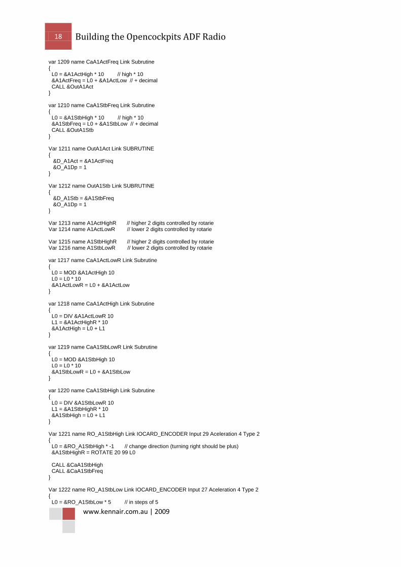
var 1209 name CaA1ActFreq Link Subrutine { L0 = &A1ActHigh * 10 // high * 10 &A1ActFreq = L0 + &A1ActLow // + decimal CALL &OutA1Act } var 1210 name CaA1StbFreq Link Subrutine { L0 = &A1StbHigh * 10 // high * 10 &A1StbFreq = L0 + &A1StbLow // + decimal CALL &OutA1Stb } Var 1211 name OutA1Act Link SUBRUTINE { &D_A1Act = &A1ActFreq &O_A1Dp = 1 } Var 1212 name OutA1Stb Link SUBRUTINE { &D_A1Stb = &A1StbFreq &O_A1Dp = 1 } Var 1213 name A1ActHighR // higher 2 digits controlled by rotarie Var 1214 name A1ActLowR // lower 2 digits controlled by rotarie Var 1215 name A1StbHighR // higher 2 digits controlled by rotarie Var 1216 name A1StbLowR // lower 2 digits controlled by rotarie var 1217 name CaA1ActLowR Link Subrutine { L0 = MOD &A1ActHigh 10 L0 = L0 * 10 &A1ActLowR = L0 + &A1ActLow } var 1218 name CaA1ActHigh Link Subrutine { L0 = DIV &A1ActLowR 10 L1 = &A1ActHighR * 10 &A1ActHigh = L0 + L1 } var 1219 name CaA1StbLowR Link Subrutine { L0 = MOD &A1StbHigh 10 L0 = L0 * 10 &A1StbLowR = L0 + &A1StbLow } var 1220 name CaA1StbHigh Link Subrutine { L0 = DIV &A1StbLowR 10 L1 = &A1StbHighR * 10 &A1StbHigh = L0 + L1 } Var 1221 name RO_A1StbHigh Link IOCARD_ENCODER Input 29 Aceleration 4 Type 2 { L0 = &RO_A1StbHigh * -1 // change direction (turning right should be plus) &A1StbHighR = ROTATE 20 99 L0 CALL &CaA1StbHigh CALL &CaA1StbFreq } Var 1222 name RO_A1StbLow Link IOCARD_ENCODER Input 27 Aceleration 4 Type 2 { L0 = &RO_A1StbLow * 5 // in steps of 5

19 Building the Opencockpits ADF Radio
www.kennair.com.au | 2009
&A1StbLowR = ROTATE 0 99 L0 &A1StbLow = MOD &A1StbLowR 10 CALL &CaA1StbHigh CALL &CaA1StbFreq } Var 1230 name Save var 1223 name FreqSwap Link IOCARD_SW Input 31 Type P { L0 = &A1ActHighR L1 = &A1ActLowR L2 = &A1ActHigh &Save = &A1ActLow &X_A1ActLow = &A1StbLow // decimal digit to fsuipc &X_A1ActHigh = TOBCD &A1StbHigh // higher 3 Digits in bcd to fsuipc &A1StbHighR = L0 &A1StbLowR = L1 &A1StbHigh = L2 &A1StbLow = &Save CALL &CaA1StbHigh CALL &CaA1StbFreq } Var 1224 name D_A1Act Link IOCARD_DISPLAY Digit 54 Numbers 4 Var 1225 name O_A1Dp Link IOCARD_OUT Output 19 Var 1226 name D_A1Stb Link IOCARD_DISPLAY Digit 49 Numbers 4