3d cubes building blocks stacked design 1 powerpoint presentation slides.

BUILDING SERVICES (BLD 60903)
Project 2 – Building Services in Public Building
Group members: Tan Wen Hao (0319923)
Wong Zhen Fai (0317890) Tang Pei Kei (0318545)
Ong Min Junn (0317767) Ong Jia Hui (0317752) Aida Junita (0317766)

ACTIVE FIRE PROTECTION SYSTEM DRY RISER SYSTEM
BY ONG JIA HUI
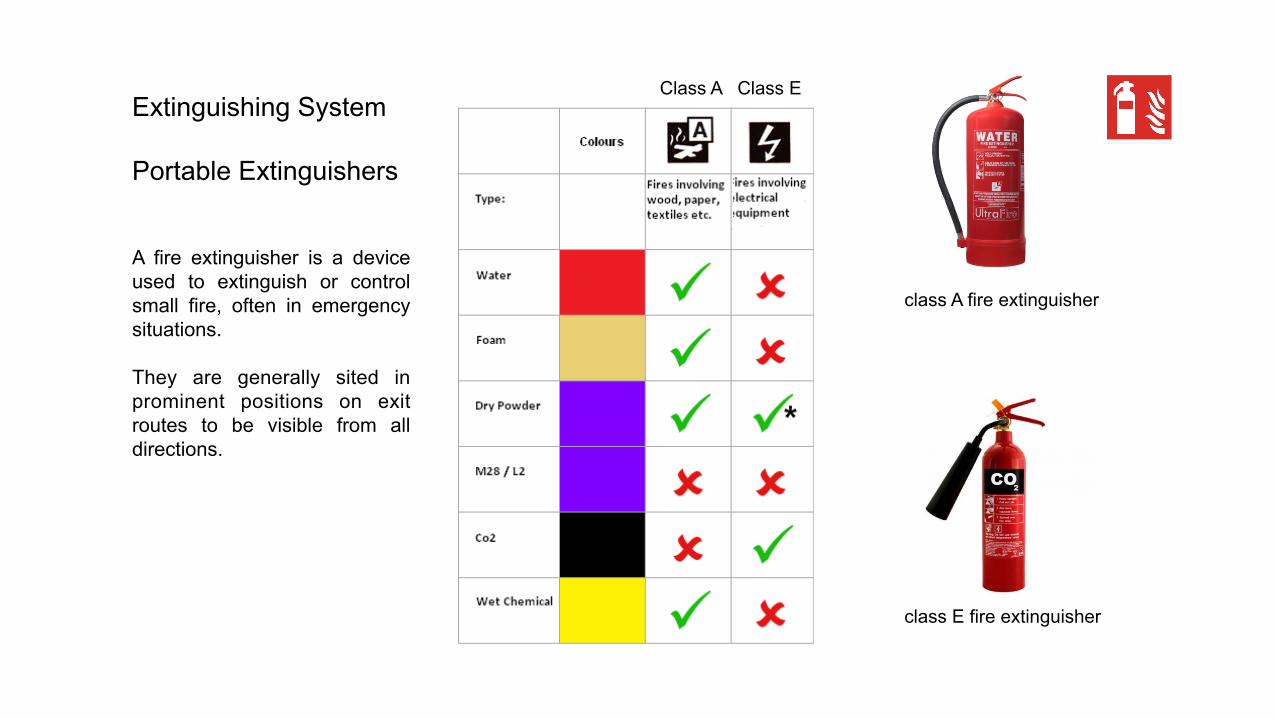
Class A Class E
class A fire extinguisher
class E fire extinguisher
Extinguishing System Portable Extinguishers A fire extinguisher is a device used to extinguish or control small fire, often in emergency situations. They are generally sited in prominent positions on exit routes to be visible from all directions.

Extinguishing System Hose Reel
Hose reel system serves as an initial fire fighting aid that is intended for the occupant to use during the early stages of fire. They are usually located along escape routes or beside exit doors or staircases.
pipe painted with primer & finished with red paint
rubber hose (pr EN 694) length: 30m diameter: 25mm
suitable for Class A fire
discharge flow rate and throw length
6 metre 30 l/min
nozzle • jet and spray adjustable type • 8mm diameter

Dry Riser System A dry riser is a vertical empty pipe that is intended to distribute water to multiple levels of a structure or building as a component of the fire suppression system. It can be externally connected to a pressurized water source by firefighters to aid in putting out the fire.

Fire Detector and Alarm System Heat, Thermal Detectors Thermal heat detectors contain a heat sensing circuit that can sense rapid i nc reases i n t empe ra tu re . I f temperature increases too fast or increases above a certain point, the detector will communicate an alarm to the fire alarm control panel.
max 5.3m
max 5.3m
Fire Alarm System
Fire alarm systems are designed to provide warning of the outbreak of fire and allow appropriate fire fighting action to be taken before the situation gets out of control.
Alarm sound: >= 100dB
Flash Period: <= 1.5s
Flash Intensity: >= 1.2WS
two-stage signal indicator alarm system
signal indicator
speaker

ground floor plan first floor plan second floor plan
Legend:
fire extinguisher
hose reel
dry riser inlet
dry riser outlet
fire alarm
heat detector

PASSIVE FIRE PROTECTION SYSTEM FIRESTOPPING AND EMERGENCY EXITS
BY TAN WEN HAO

Fire stopping system -Fire protection on A/C system
Figure 4 Galvanized steel fireproof A/C duct
Sheet metal duct: Made from galvanized steel, these ducts can be rectangular or round. One duct section usually slides into another. The ducts are highly fireproof because of its good insulation property and able to stand extreme heat.
Components of systems:
Fire damper: A device designed to impede the spread of fire through walls, floors and partitions. Its construction includes a galvanized steel frame and a fusible link, a heat sensitive device (usually set at 165° F). When the fusible link opens it releases the damper components to close. When the damper components close the damper will restrict the migration of fire. Fire damper products are listed with hourly ratings. In this case, 1 ½ hour fire dampers are used to comply with the 1-hour and 2 –hour fire stopping wall in this building
Smoke extraction duct: used in emergency exhaust ventilation systems for forced extraction of smoke and heated gases and simultaneous transfer of heat generated by the fire away and beyond the limits of the serviced spaces where the ignition occurs. Such units are used in production, public, residential, administrative and other spaces. Such fans are capable of handling smoke and air mixtures with temperatures up to 600 °С.

Firestoppingsystem-Fire-stoppingwall
Components of systems:
Fire-rated wall: Fire-rated walls can be used to subdivide a building into separate fire areas and are constructed in accordance with the locally applicable building codes. Firewalls are a portion of a building's passive fire protection systems. Thermal and acoustic 60 minute fire rated fire stops for installation within external cavity and brick walls can be used in this buiilding to restrict the spread of smoke and flame and minimize the effect of flanking noise at wall junctions.
Penetrating cable lines and pipes: an assemblage of materials designed to prevent the spread of fire and its byproducts for a prescribed period of time through openings which are made in floors and walls to accommodate through penetrating items such as ducts, metal and plastic pipes, electrical conduit, cables, cable trays
Intumescent Wall Paint: help keep building as safe as possible in the event of a fire with the application of fire retardant coatings.

Part two of Ninth Schedule: Buildings storey buildingsFigure 15: Nine schedule of UBBL (Limits of compatments and minimum periods of fire resistance for elements of structure

Meansofescape-Exits(halfhourandonehourdoor)
Components of systems:
Door material: The fire-rated door is made of wood with 60mm thick of chock layer in between compressed with two sides of 20mm fire-treated wood block. The thickness of door and material plays a big role in resisting heat and pressure in both side of room. The layer of chock provides extra strength as a high heat barrier while fire proof paint coated at surface of door helps withstand high temperature to make sure the door bear the heat and fire for a longer period of time.
Door closer:A door closer is a mechanical device that closes a door, in general after someone opens it, or after it was automatically opened. Door closers are most commonly installed on fire doors, which need to be closed in case of fire, to help prevent the spread of fire and smoke. Door closer also play a role in maintaining average cooling temperatures, since colder air does not vent out for longer periods if the door remains closed for longer periods on average.

Ground floor First floor Second floor
Fire stopping wall diagram
Ground floor First floor Second floor
Half hour fire-rated wood door
Half hour fire-rated wood door one hour fire-rated
wood door
one hour fire-rated steel door
Fire-stopping door diagram
UBBL Law 161: Fire-stopping a. Any fire stop required by the provisions of this Part shall be so formed and
positioned as to prevent or retard the passage of flame.b. Any fire stop shall ;
• if provided around a pipe or duct or in a cavity, be made of non-combustible material or if it is in a floor or wall thick; and material, of timber not less than 37 millimetres
• if provided around a pipe or duct, be so constructed as not to restrict essential thermal movement. of
a. Any fire stop formed as a seal at the junction of two or more element structure shall be made of non-combustible material
UBBL Law 164:
All fire doors shall be fitted with automatic door closers of the hydraulically spring operated type in the case of swing doors and of wire rope and weight type in the case of sliding doors.
UBBL Law 173:
All exit doors shall be openable from the inside without the use of key or any special knowledge or effort Exit doors shall close automatically when released and all door devices including magnetic door holders, shall release the doors upon power failure or actuation of the fire alarm.
a single door 900 m wide x 2100 millimetres high maximum or constructed of solid hardwood core of not less than 37 millimetres laminated with adhesives conforming to either BS 745 "Animal Glues or BS 1204 Synthetic resin adhesives (phenolic and aminoplastic) for wood" Part I, "Gap-filling adhesives or BS 1444, "Cold setting casein glue for wood", faced both sides with plywood to a total thickness of not less than 43 millimetres with all edges finished with a solid edge strip full width of the door

Meansofescape-Emergencyexits(roomexits)
Room/area Travel8me Max.TravelDist. Room/area Travel8me Max.TravelDist.
Lobby 1min 7.8M Humanlibrary 2mins 8M
Staffoffice 1min 8M M&Eroom 30secs 3M
Theatre 5mins 10M Director’sOffice 4mins 6M
DiningLounge 2mins 8.6M Library 6mins 17M
Ground floor First floor Second floor
UBBL Law 165 travel distances: Provided that the travel distance from any point in the room to the room door does not exceed 15 metres.
The maximum travel distances to exists and dead end limits shall be as specified in the Seventh Schedule of these By-laws.
Maximum 30m of travel distances required in
an elderly home.
Diagram of emergency exits

UBBL law 167 storey exits
Except as provided for in by-law 194 every compartment shall be provided with at least two storey exits located as far as practical from each other and in no case closer than 4.5 metres and in such position that the travel distances specified in the Seventh Schedule to these By-laws are not exceeded.
Meansofescape-Emergencyexits(storeyexits)
Ground floor First floor Second floor
Primary emergency
stairs
Secondary emergency
stairs
15M distances from both stairs
Location Distances Width
UBBL law 168 Staircase
Except as provided for in by-law 194 every upper floor shall have means of egress via at least two separate staircase.
Diagram of storey exits location
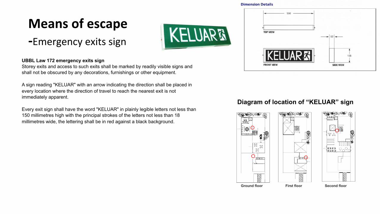
Meansofescape-Emergencyexitssign
UBBL Law 172 emergency exits sign Storey exits and access to such exits shall be marked by readily visible signs and shall not be obscured by any decorations, furnishings or other equipment. A sign reading "KELUAR" with an arrow indicating the direction shall be placed in every location where the direction of travel to reach the nearest exit is not immediately apparent. Every exit sign shall have the word "KELUAR" in plainly legible letters not less than 150 millimetres high with the principal strokes of the letters not less than 18 millimetres wide, the lettering shall be in red against a black background.
Ground floor First floor Second floor
Diagram of location of “KELUAR” sign

Overall passive fire protection system on plan
MECHANICAL VENTILATION BALANCED VENTILATION SYSTEM
BY TANG PEI KEI

Why Balanced ventilation system?
• Balanced combined ventilation system which the inlet and outlet both which means that the air is supplied in and extracted with the help of mechanical devices. Hence, causing the pressure level in the internal space to remain at neutral.
• The internal space of a building can be ventilated with the use of two different sets of ductwork and also fan system. It's not affected by the outdoor weather and is known as a more efficient ventilation system.
Figure1.1SchemaOcDiagramshowstheoperaOonofthebalancedvenOlaOonsysteminabuilding.

Multi-Point ERV with Partial Connection to Central Air Handler
• Energy recovery ventilation systems provide a controlled way of ventilating a home while minimizing energy loss. They reduce the costs of heating ventilated air in the winter by transferring heat from the warm inside exhaust air to the fresh (but cold) outside supply air
• In the summer, an energy-recovery ventilator may help to control humidity in the house by transferring some of the water vapor in the incoming air to the theoretically drier air that's leaving the house.
Figure1.2DiagramsaboveshowsoneofthesampleofmechanicalvenOlaOonsystem.
Figure1.3DiagramsaboveshowsthedetailsofairmovementinERVsystem.
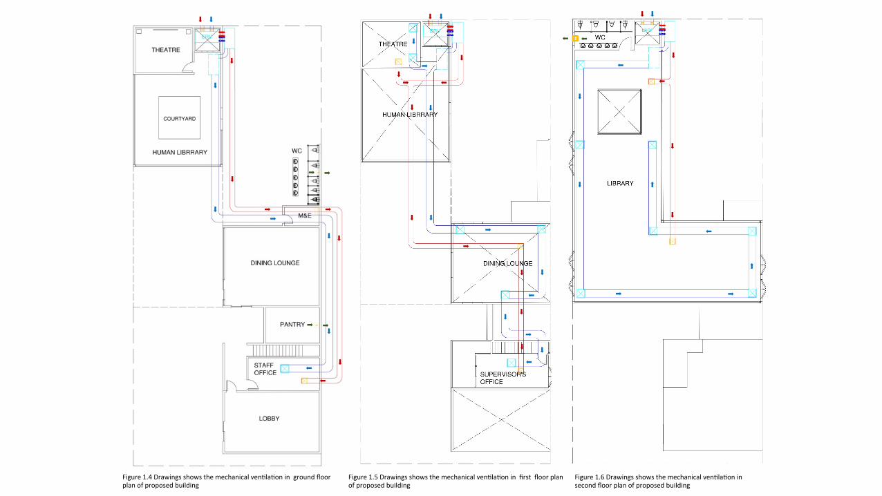
Figure1.4DrawingsshowsthemechanicalvenOlaOoningroundfloorplanofproposedbuilding
Figure1.5DrawingsshowsthemechanicalvenOlaOoninfirstfloorplanofproposedbuilding
Figure1.6DrawingsshowsthemechanicalvenOlaOoninsecondfloorplanofproposedbuilding

Component
• Fan Exhaust fan
• Filters
• Ductwork Galvanized steel duct
• Fire Dampers • Diffusers
Louvers air outlet, Square air outlet
Figure1.7DrawingsshowsthemechanicalvenOlaOoninsecOonoftheproposedbuilding.
Figure1.8PictureshowsthecomponentoftypicalresidenOalmechanicalvenOlaOonsystem.
AirHandler

Fan Fan serves the purpose of removing hot, humid and polluted air, it's often used to bring in outdoor air to encourage ventilation and cool the internal spaces of a building.
PropellerFan/ExhaustFan
Advantages: -Usually used without ducting -Remove large amount of air -Low cost of installation
Located in the elevator control , usually is connected to a temperature thermostat, it will be switched on automatically once the detector detected a high temperature in the room. Plays the role of removing the hot air from the control room to prevent overheating of the wire and mechanical components in the room.

According to Building By-Laws 1984 Clause 258 THIRD SCHEDULE (By-law 41) 12. Fresh Air Changes (1) The minimum scale of fresh air ventilation in conjunction with
recirculated, filtered and conditioned air meeting with the requirements of ASHRAE STANDARD 62-73 shall be as follows: Commercial premises 0.14 cm per occupant
(2) The minimum scale of fresh air ventilation in conjunction with the mechanical ventilation systems shall be as follows: Commercial premises (excluding laundry and boiler houses) 0.28 cm per occupant
Figure1.9DrawingaboveshowsthezoominfloorplanofWC,M&EandPantry,emphasizingtheexhaustfan.
Figure1.9DrawingaboveshowsthezoominfloorplanofWCinsecondfloorplan,emphasizingtheexhaustfan.
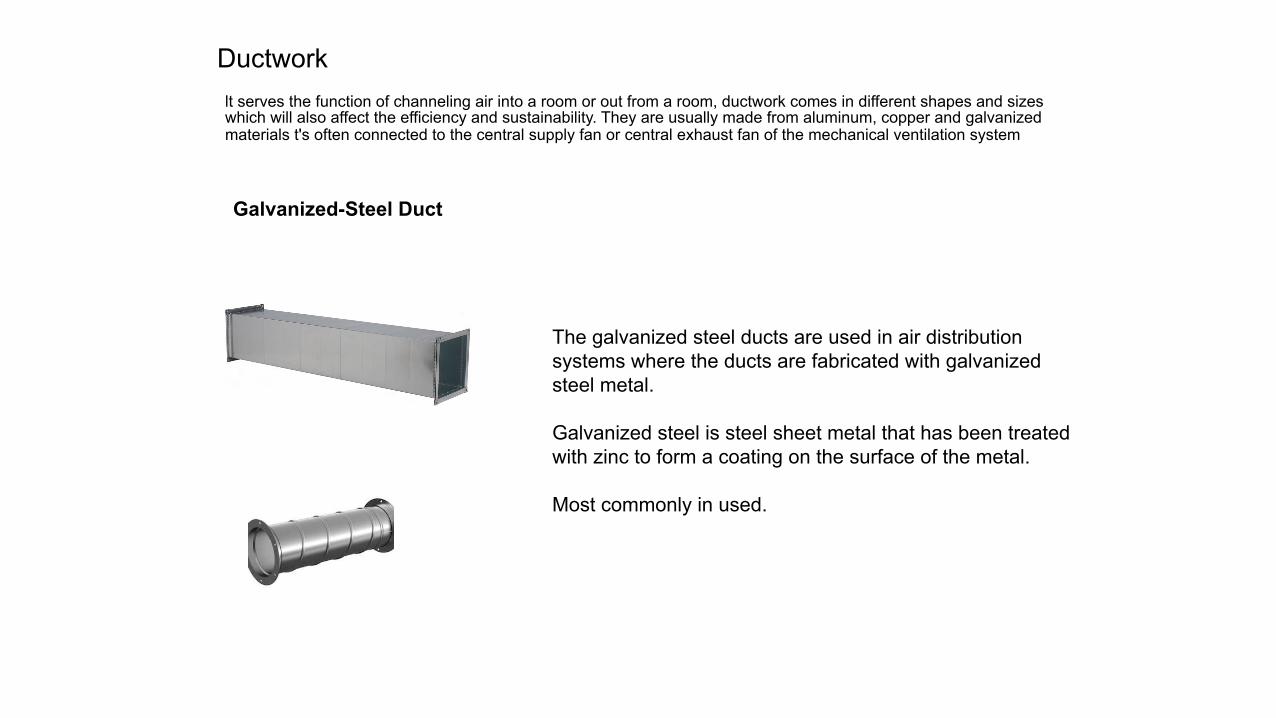
Ductwork lt serves the function of channeling air into a room or out from a room, ductwork comes in different shapes and sizes which will also affect the efficiency and sustainability. They are usually made from aluminum, copper and galvanized materials t's often connected to the central supply fan or central exhaust fan of the mechanical ventilation system
Galvanized-Steel Duct
The galvanized steel ducts are used in air distribution systems where the ducts are fabricated with galvanized steel metal. Galvanized steel is steel sheet metal that has been treated with zinc to form a coating on the surface of the metal. Most commonly in used.

Dampers Damper is the valve that serves the purpose of regulating the air flow inside a ducting or other air handling equipment. It also help to regulate the internal temperature of a room. The operation time can be controlled with the use of thermostat system.
Fire Damper
Fire damper can be seen installed at a higher level on the external walls in the stairwell. It is to prevent the fire from spreading out to the building next to it.
It acts as a pressure relief damper which helps to reduce the pressure created by supply ventilation pressured staircases system. The economizer-damper controller sends a signal to control outside-, return-, and relief-air dampers, with the return-air dampers operating opposite of the outside- and relief-air dampers. It is connecting with the supply air ducting.
Air Pressure Relief Damper

According to Building By-Laws 1984 Clause 199 Ventilation of staircase enclosures in buildings not exceeding 18 metres Ventilation of staircase enclosures in buildings not exceeding 18 metres. In buildings not exceeding 18 metres above ground staircase level. enclosures may be unventilated provided that access to them at all levels except the top floor is through ventilated lobbies and the staircase enclosures are permanently ventilated at the top with at least 5% of the area of the enclosures. Therefore, fire damper does not propose in our building.

Diffuser It’s the mechanical devices that usually located at the end of a ductwork system which air is been released from. It's a typical outlet used for air to release from the connecting ductwork. They come in different sizes and shapes which serve different functions as well.
Square air diffuser
This particular square air diffuser functions as a medium to supply chilled air into the rooms. Usually located at the ceiling
Single grill air outlet
This serves as an outlet for the hot air drew by the exhaust fan in the utility rooms like the telecom room, elevator control room, and electrical supply room. It prevents overheating from damaging the mechanical devices in these rooms. It also acts as outlet for humid air drew out from the water supply system.

PASSIVE VENTILATION OPENING & NATURAL LIGHTING
BY ONG MIN JUNN

Sec8on39–NaturalLigh8ngandVen8la8onClause2EveryroomusedfortheaccommodaOonofpaOentsinahospitalshallbeprovidedwithnaturallighOngandnaturalvenOlaOonbymeansofoneormorewindowshavingatotalareaofnotlessthan15%oftheclearfloorareaofsuchroomandshallhaveopeningscapableofallowingafreeuninterruptedpassageofairofnotlessthan10%ofsuchfloorarea.
OpeningsinRooms AreaofOpening
ForLighOng >15%offloorarea
ForVenOlaOon >10%offloorarea

GroundFloorPlan-ConsisOngof3mainspaces-Mainlycross-venOlatednaturallyexceptforspaceA-MinimumareaofopeningsforvenOlaOon:-CurrentdesignhassucceededtheminimumrequirementofopeningsforvenOlaOonasstatedbelow:
Room FloorArea(sqm)
Min.AreaofVen8la8ons(sqm)
A 55 5.5
B 49 4.9
C 37 3.7
Room AreaofOpenings(sqm)
A 6
B 10
C 5Figure1.1:GroundFloorPlanwithHighlightedRoomAreas
A
B
C

FirstFloorPlan-ConsisOngofonly1mainspace-Otherspacesaredoublevolumesofspacesfromgroundfloor-MinimumareaofopeningsforvenOlaOon:-CurrentdesignhassucceededtheminimumrequirementofopeningsforvenOlaOonasstatedbelow:
Room FloorArea(sqm)
Min.AreaofVen8la8ons(sqm)
D 15 1.5
Room AreaofOpenings(sqm)
D 4.5DFigure1.2:FirstFloorPlanwithHighlightedRoomAreas

SecondFloorPlan-ConsisOngof1largespace-MechanicallyvenOlatedwithaircondiOonerandusageofnaturalvenOlaOonaswell-MinimumareaofopeningsforvenOlaOon:-CurrentdesignhassucceededtheminimumrequirementofopeningsforvenOlaOonasstatedbelow:
Room FloorArea(sqm)
Min.AreaofVen8la8ons(sqm)
E 180 18
Room AreaofOpenings(sqm)
E 20
E
Figure1.3:SecondFloorPlanwithHighlightedRoomAreas
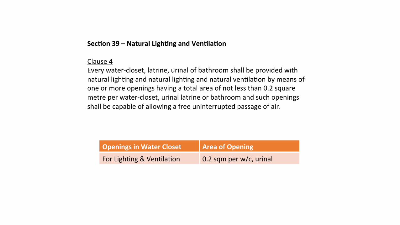
Sec8on39–NaturalLigh8ngandVen8la8onClause4Everywater-closet,latrine,urinalofbathroomshallbeprovidedwithnaturallighOngandnaturallighOngandnaturalvenOlaOonbymeansofoneormoreopeningshavingatotalareaofnotlessthan0.2squaremetreperwater-closet,urinallatrineorbathroomandsuchopeningsshallbecapableofallowingafreeuninterruptedpassageofair.
OpeningsinWaterCloset AreaofOpening
ForLighOng&VenOlaOon 0.2sqmperw/c,urinal

TOILET-2toiletsthroughouttheenOrebuildingwithatotalof9cubicles-CurrentareaofopeningforvenOlaOon:
Figure2.1:HighlightedlocaOonoftoiletsingroundfloor
plan(right)andsecondfloorplan(lee)
Toilet Cubicles Min.AreaofVen8la8ons
(sqm)
A 5 1.0
B 4 0.8
Toilet AreaofOpeningsforVen8la8on(sqm)
A 1.0
B 1.2
A
B

Sec8on40–Air-wellsClause1(a)Theminimumsizeofeachair-wellwhereprovidedinallbuildingsshallbeasfollows:forbuildingsupto4storeysinheight,9squaremetres;Clause1(b)Theminimumwidthofsuchair-wellsinanydirecOonshallbe2.5metres. Air-wellSize AreaofAir-well
Forbuildingsupto4storeys >9sqmwithmin.widthof2.5m

AIR-WELLBuildingheightof3storeys,thereforeitrequiresanairwellwithaminimumof9sqm.CurrentAreaofair-well=11.5sqmDimension=3.3mx3.4mThepresenceofairwellallowstheflowofairverOcally,drawingairupwardstobethroughtheVenturieffectthusreducingtheneedforanopeningforvenOlaOonontheoppositeendofthecasementwindows.
Figure3.1:HighlightedlocaOonofair-wellongroundfloor
plan

Sec8on111–Ligh8ngandven8la8onatstaircaseAllstaircasesshallbeproperlylightedandvenOlatedaccordingtotherequirementsofthelocalauthority.
BothlandingsofthestairsarewellvenOlatedandlightedwiththelowerlandingbeingexposedtoanopencorridorwhiletheupperlandingisexposedtoatophungwindow.AwindowisplacedabovethestairsonthefirstflooraswelltoensureproperlighOng.
Figure4.1:HighlightedlocaOonofwindowopeningsthatvenOlatestaircasesingroundfloor(above)andfirstfloor(below)

AIR-CONDITIONING SYSTEM PACKAGED UNIT SYSTEM A I R - C O O L E D
BY WONG ZHEN FAI
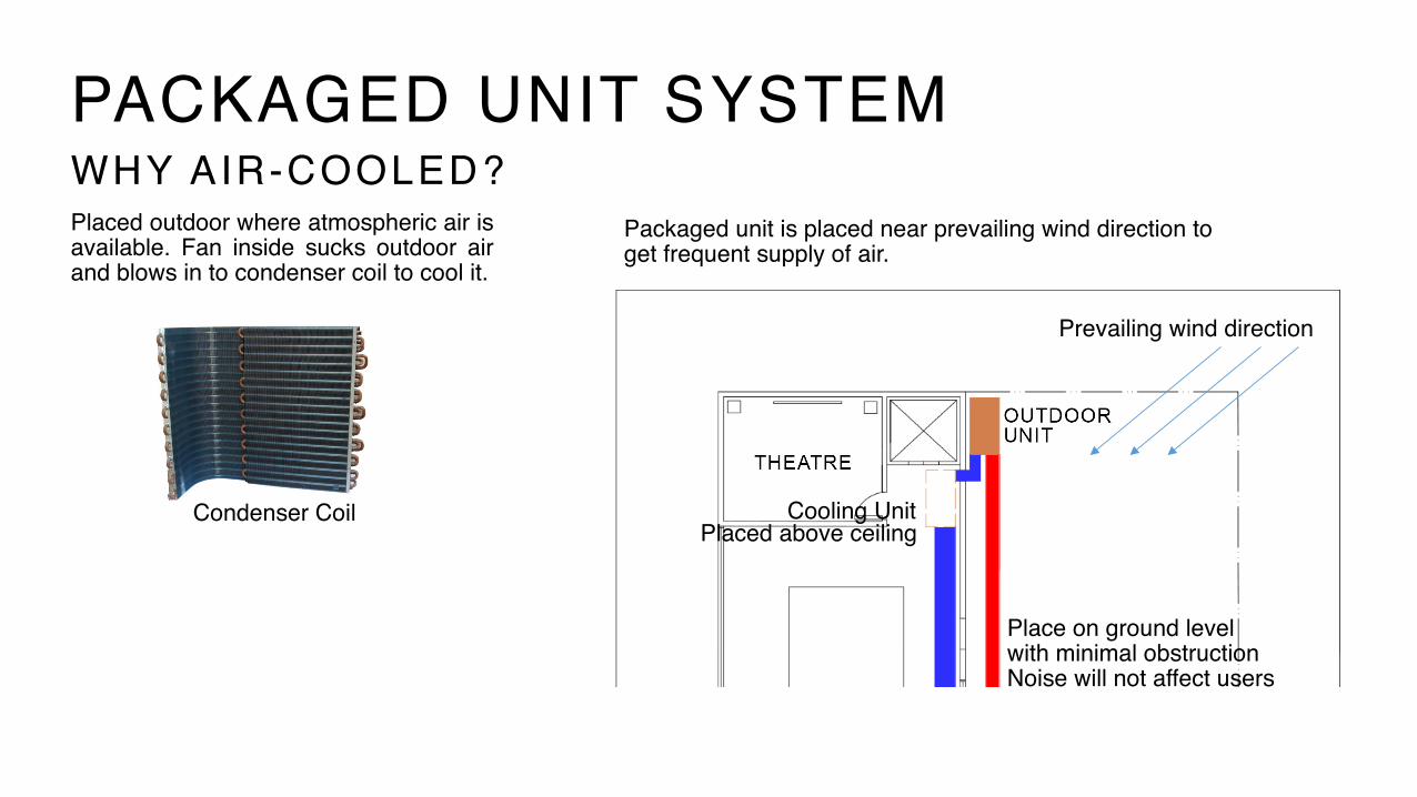
PACKAGED UNIT SYSTEMWHY AIR-COOLED?Placed outdoor where atmospheric air is available. Fan inside sucks outdoor air and blows in to condenser coil to cool it.
Packaged unit is placed near prevailing wind direction to get frequent supply of air.
Cooling Unit
Prevailing wind direction
Placed above ceiling
Place on ground level with minimal obstruction Noise will not affect users
Condenser Coil

Packaged Unit Cross Section
PACKAGED UNIT SYSTEMCOMPONENTSOUTDOOR UNIT INDOOR UNIT
Contains condenser, condenser coils, compressor, blower fans.
C o n t a i n s e x p a n s i o n v a l v e , evaporator, air handling blower and filter. May be placed at ground floor or above ceiling.
R e f r i g e r a n t P i p i n g

GROUND FLOOR FIRST FLOOR SECOND FLOOR
DUCTING PLAN

PRODUCT SPECIFICATIONS
GOODMAN

MECHANICAL TRANSPORTATION SYSTEM ELEVATOR AND ESCALATOR / TRAVELLATOR SYSTEMS
BY AIDA JUNITA

estimated dimensions + sizes
The following are the estimated dimensions and sizes of spaces required for mechanical transportation system in the elderly community center:
mechanical transportation system | project 2 – building services in public buildings
Figure 3: Lift car requirement from MS 1184:2002
Figure 1: Ground floor plan of elderly community center
Figure 2: Estimated dimensions/sizes of elevator proposed
Location of elevator
2150 mm
2000
mm
900 mm
type of lift
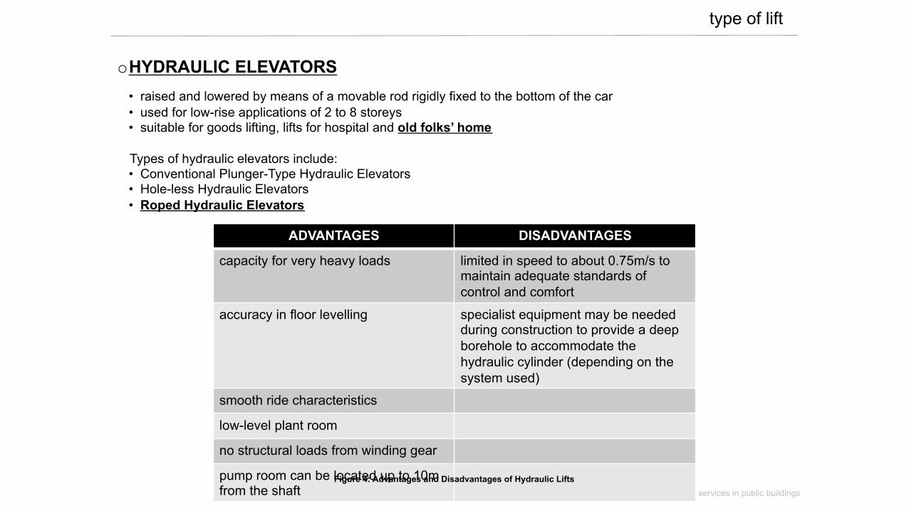
o HYDRAULIC ELEVATORS • raised and lowered by means of a movable rod rigidly fixed to the bottom of the car • used for low-rise applications of 2 to 8 storeys • suitable for goods lifting, lifts for hospital and old folks’ home
Types of hydraulic elevators include: • Conventional Plunger-Type Hydraulic Elevators • Hole-less Hydraulic Elevators • Roped Hydraulic Elevators
mechanical transportation system | project 2 – building services in public buildings
ADVANTAGES DISADVANTAGES
capacity for very heavy loads limited in speed to about 0.75m/s to maintain adequate standards of control and comfort
accuracy in floor levelling specialist equipment may be needed during construction to provide a deep borehole to accommodate the hydraulic cylinder (depending on the system used)
smooth ride characteristics
low-level plant room
no structural loads from winding gear
pump room can be located up to 10m from the shaft
Figure 4: Advantages and Disadvantages of Hydraulic Lifts

components + operation of system
Brief description on the roped hydraulic elevator components:
mechanical transportation system | project 2 – building services in public buildings
Figure 5: Roped Hydraulic Elevator – Single Jack and a Cantilevered Car
T h e r o p e d h y d r a u l i c arrangement is simpler as it only uses a single unit moving jack section.
The simplicity and reliability of the single- or double jack roped arrangement have made it by far the most common choice for low-rise, light- to medium-duty hydraulic elevators.

example of roped hydraulic elevator
mechanical transportation system | project 2 – building services in public buildings
Figure 6: The Schumacher Hospital Single Opening Roped Hydraulic Elevator
Schumacher Roped Hydraulic Elevator - Designed for mid-rise buildings having up to 70
feet (21m) of rise - Less expensive option - Minimal pit and overhead requirements - Less hoistway dimensions needed - Eliminates cost of dri l l ing and r isk of
contamination

example of roped hydraulic elevator
mechanical transportation system | project 2 – building services in public buildings
Figure 7: The Schumacher Hospital Single Opening Roped Hydraulic Elevator Drawings