BUILDING & ROOFING SYSTEM CONSTRUCTION …€¢ Never allow moisture on or between any steel...
75
F F U U T T U U R R E E S S T T E E E E L L B B U U I I L L D D I I N N G G S S ® BUILDING & ROOFING SYSTEM CONSTRUCTION GUIDELINES © FUTURE STEEL BUILDINGS INTL. CORP., 2011 “FUTURE STEEL” IS A REGISTERED TRADEMARK OF FUTURE STEEL HOLDINGS, LTD. - ALL RIGHTS RESERVED
-
Upload
nguyendiep -
Category
Documents
-
view
217 -
download
3
Transcript of BUILDING & ROOFING SYSTEM CONSTRUCTION …€¢ Never allow moisture on or between any steel...
FFUUTTUURREE SSTTEEEELL
BBUUIILLDDIINNGGSS®®
BUILDING & ROOFING SYSTEM CONSTRUCTION GUIDELINES
© FUTURE STEEL BUILDINGS INTL. CORP., 2011 “FUTURE STEEL” IS A REGISTERED TRADEMARK OF
FUTURE STEEL HOLDINGS, LTD. - ALL RIGHTS RESERVED

1
QUESTIONS If at any time you have questions about the construction of your building, do not proceed. Contact our Techni-cal Support Department at (800) 387-2343. If you are calling from an area in which our toll free number does not work, please use our local number, (905) 790-8500. Have your order number ready, so that we may better as-sist you. Your order number is located on your bill of lading and in the bottom right hand corner of your blue-print. Record your order number and building model in the space provided below for future reference:
STORAGE GUIDELINES To help prevent staining or discoloration to your building components during storage, please observe the following guidelines:
• Store the components indoors in a dry, well-ventilated area; • Cut the banding on all bundles and pallets to allow air to circulate freely around each component; and • Never allow moisture on or between any steel components prior to construction. An acrylic coating has been applied to the Galvalume Plus® steel by the mill which provides added protection during the shipment and storage of the building components. The coating will protect the steel for a short period of time if your building components are stored outdoors. Indoor storage is strongly recommended. Our panels should not be stored for an extended period of time to avoid staining, discoloration and deformation. We do not recommend and will not be responsible for outdoor storage. If you must store your building compo-nents outdoors, we strongly recommend that you take the following additional precautions to reduce the likeliness of staining or discoloration:
• Lay a tarp or moisture barrier on the ground; • Do not set in vegetation, as doing so will result in the deterioration of the protective coating on the steel; • Cut the banding and separate all components with dry pieces of wood so that no two pieces of steel are in contact; • Ensure that water or moisture does not accumulate on or in any of the steel components; and • Do not simply cover the bundles and pallets with tarps. Doing so will not prevent moisture damage that
can occur as a result of condensation. CAUTION: If two damp pieces of steel are in contact, a gray, white or black deposit known as a wet stor-
age stain will form on the surface of the steel. The guidelines listed above will help prevent such staining and/or discoloration, which is not covered by any warranty.
NOTE: We are not responsible for any damage that occurs after the building components leave our
facility, including, without limitation, staining or discoloration caused by improper storage. Therefore, it is in your own interest to follow the above guidelines and take all other necessary precautions. Storage stains cannot be removed and can only be coated.
CONSTRUCTION AND BUILDING INSURANCE We recommend that you inform your insurance company of the purchase of your building components. Your insurance policy should be adjusted before you begin construction. Also, a rider on your policy for construction insurance could protect you and your investment in the event an unforeseen problem. ENSURE THAT YOUR PRODUCT IS SUITABLE FOR YOUR AREA You must check with a local authority (i.e. Planning or Building Department) to determine if a building permit is required and to ensure the constructed building will comply with all local requirements before you begin construction.
CAUTION: Your building will not reach its designed load capacity until it is fully and correctly assembled
and completed in full accordance with our blueprint.
IMPORTANT NOTICE: PLEASE READ THESE GUIDELINES IMMEDIATELY UPON RECEIVING YOUR
BUILDING COMPONENTS AND AGAIN BEFORE AND DURING CONSTRUCTION
ORDER NUMBER: MODEL:

2
3
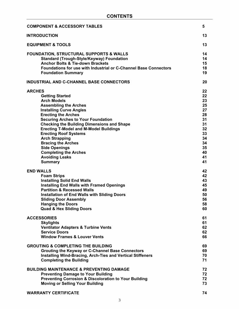
CONTENTS
COMPONENT & ACCESSORY TABLES 5 INTRODUCTION 13 EQUIPMENT & TOOLS 13 FOUNDATION, STRUCTURAL SUPPORTS & WALLS 14
Standard (Trough-Style/Keyway) Foundation 14 Anchor Bolts & Tie-down Brackets 15 Foundations for use with Industrial or C-Channel Base Connectors 18 Foundation Summary 19
INDUSTRIAL AND C-CHANNEL BASE CONNECTORS 20 ARCHES 22
Getting Started 22 Arch Models 23
Assembling the Arches 25 Installing Curve Angles 27
Erecting the Arches 28 Securing Arches to Your Foundation 31 Checking the Building Dimensions and Shape 31 Erecting T-Model and M-Model Buildings 32 Erecting Roof Systems 33 Arch Strapping 34 Bracing the Arches 34 Side Openings 35 Completing the Arches 40 Avoiding Leaks 41 Summary 41
END WALLS 42
Foam Strips 42 Installing Solid End Walls 43 Installing End Walls with Framed Openings 45 Partition & Recessed Walls 49 Installation of End Walls with Sliding Doors 50 Sliding Door Assembly 56 Hanging the Doors 58
Quad & Hex Sliding Doors 60 ACCESSORIES 61
Skylights 61 Ventilator Adapters & Turbine Vents 62 Service Doors 62 Window Frames & Louver Vents 66
GROUTING & COMPLETING THE BUILDING 69 Grouting the Keyway or C-Channel Base Connectors 69 Installing Wind-Bracing, Arch-Ties and Vertical Stiffeners 70 Completing the Building 71
BUILDING MAINTENANCE & PREVENTING DAMAGE 72
Preventing Damage to Your Building 72 Preventing Corrosion & Discoloration to Your Building 72 Moving or Selling Your Building 73
WARRANTY CERTIFICATE 74
4
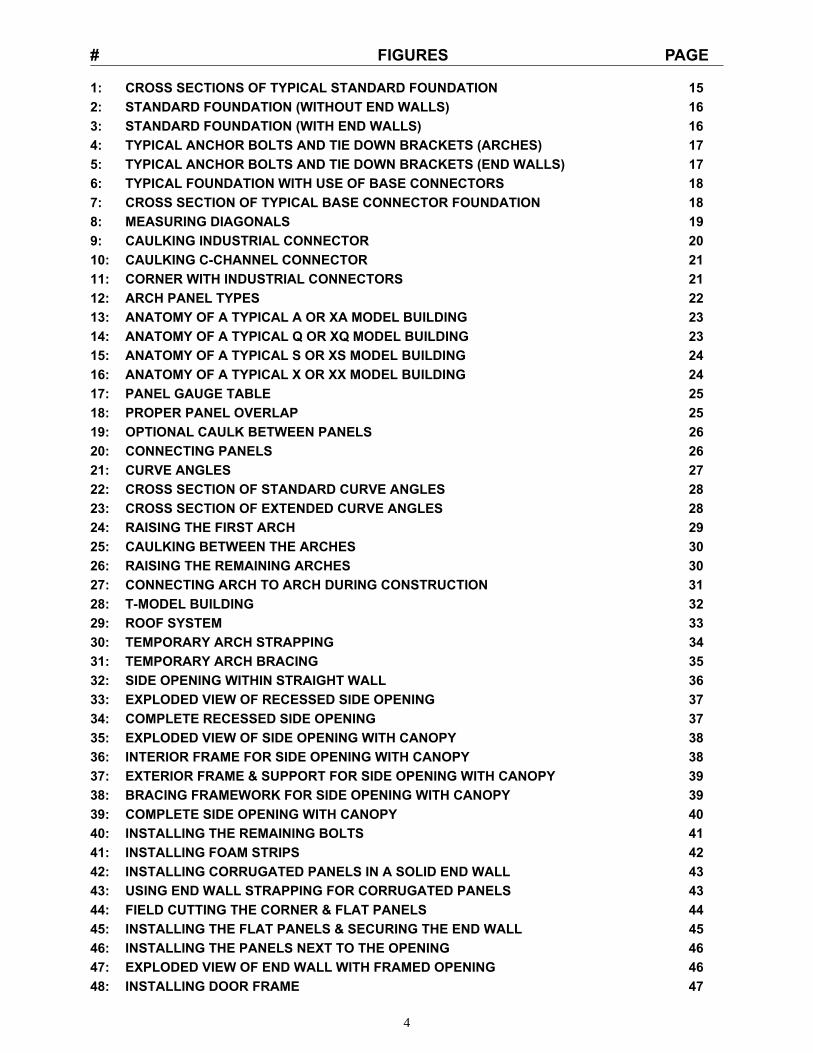
# FIGURES PAGE 1: CROSS SECTIONS OF TYPICAL STANDARD FOUNDATION 15 2: STANDARD FOUNDATION (WITHOUT END WALLS) 16 3: STANDARD FOUNDATION (WITH END WALLS) 16 4: TYPICAL ANCHOR BOLTS AND TIE DOWN BRACKETS (ARCHES) 17 5: TYPICAL ANCHOR BOLTS AND TIE DOWN BRACKETS (END WALLS) 17 6: TYPICAL FOUNDATION WITH USE OF BASE CONNECTORS 18 7: CROSS SECTION OF TYPICAL BASE CONNECTOR FOUNDATION 18 8: MEASURING DIAGONALS 19 9: CAULKING INDUSTRIAL CONNECTOR 20 10: CAULKING C-CHANNEL CONNECTOR 21 11: CORNER WITH INDUSTRIAL CONNECTORS 21 12: ARCH PANEL TYPES 22 13: ANATOMY OF A TYPICAL A OR XA MODEL BUILDING 23 14: ANATOMY OF A TYPICAL Q OR XQ MODEL BUILDING 23 15: ANATOMY OF A TYPICAL S OR XS MODEL BUILDING 24 16: ANATOMY OF A TYPICAL X OR XX MODEL BUILDING 24 17: PANEL GAUGE TABLE 25 18: PROPER PANEL OVERLAP 25 19: OPTIONAL CAULK BETWEEN PANELS 26 20: CONNECTING PANELS 26 21: CURVE ANGLES 27 22: CROSS SECTION OF STANDARD CURVE ANGLES 28 23: CROSS SECTION OF EXTENDED CURVE ANGLES 28 24: RAISING THE FIRST ARCH 29 25: CAULKING BETWEEN THE ARCHES 30 26: RAISING THE REMAINING ARCHES 30 27: CONNECTING ARCH TO ARCH DURING CONSTRUCTION 31 28: T-MODEL BUILDING 32 29: ROOF SYSTEM 33 30: TEMPORARY ARCH STRAPPING 34 31: TEMPORARY ARCH BRACING 35 32: SIDE OPENING WITHIN STRAIGHT WALL 36 33: EXPLODED VIEW OF RECESSED SIDE OPENING 37 34: COMPLETE RECESSED SIDE OPENING 37 35: EXPLODED VIEW OF SIDE OPENING WITH CANOPY 38 36: INTERIOR FRAME FOR SIDE OPENING WITH CANOPY 38 37: EXTERIOR FRAME & SUPPORT FOR SIDE OPENING WITH CANOPY 39 38: BRACING FRAMEWORK FOR SIDE OPENING WITH CANOPY 39 39: COMPLETE SIDE OPENING WITH CANOPY 40 40: INSTALLING THE REMAINING BOLTS 41 41: INSTALLING FOAM STRIPS 42 42: INSTALLING CORRUGATED PANELS IN A SOLID END WALL 43 43: USING END WALL STRAPPING FOR CORRUGATED PANELS 43 44: FIELD CUTTING THE CORNER & FLAT PANELS 44 45: INSTALLING THE FLAT PANELS & SECURING THE END WALL 45 46: INSTALLING THE PANELS NEXT TO THE OPENING 46 47: EXPLODED VIEW OF END WALL WITH FRAMED OPENING 46 48: INSTALLING DOOR FRAME 47
5
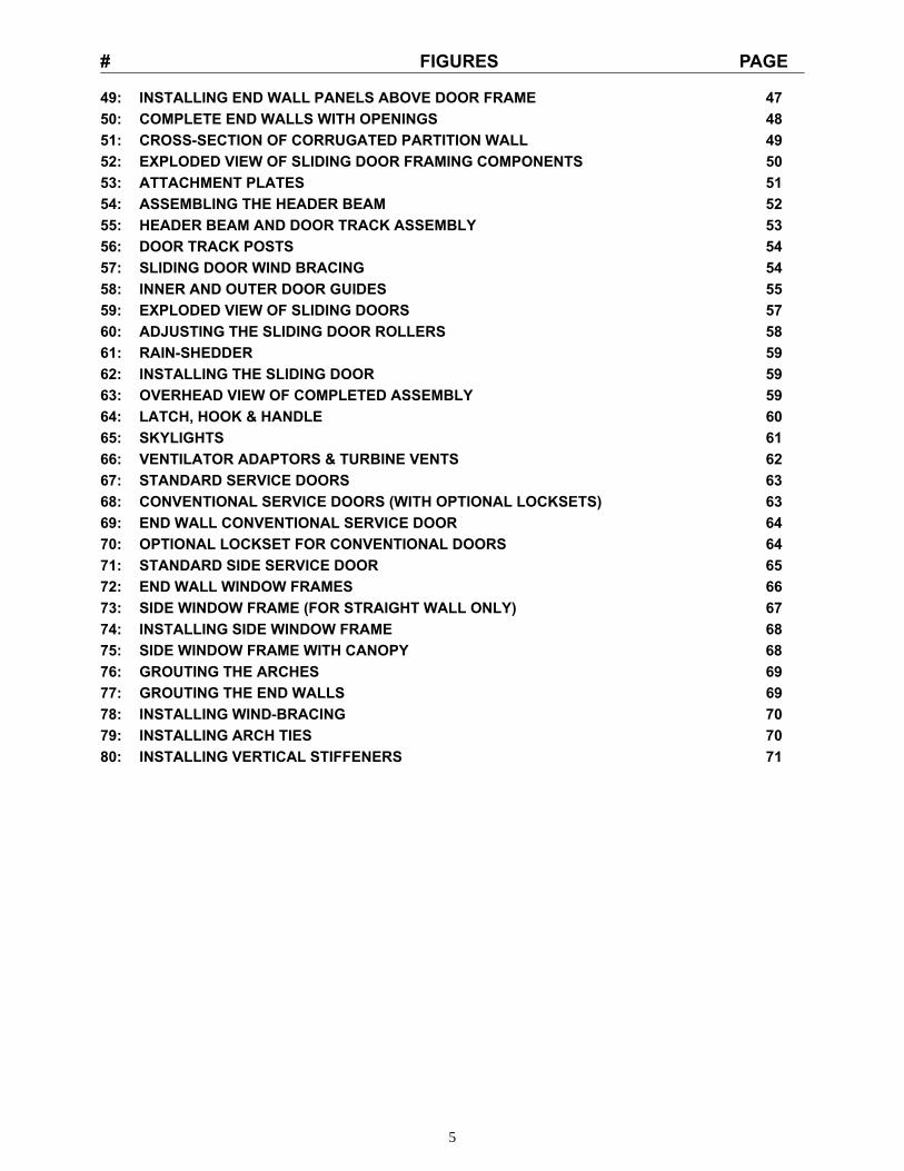
# FIGURES PAGE 49: INSTALLING END WALL PANELS ABOVE DOOR FRAME 47 50: COMPLETE END WALLS WITH OPENINGS 48 51: CROSS-SECTION OF CORRUGATED PARTITION WALL 49 52: EXPLODED VIEW OF SLIDING DOOR FRAMING COMPONENTS 50 53: ATTACHMENT PLATES 51 54: ASSEMBLING THE HEADER BEAM 52 55: HEADER BEAM AND DOOR TRACK ASSEMBLY 53 56: DOOR TRACK POSTS 54 57: SLIDING DOOR WIND BRACING 54 58: INNER AND OUTER DOOR GUIDES 55 59: EXPLODED VIEW OF SLIDING DOORS 57 60: ADJUSTING THE SLIDING DOOR ROLLERS 58 61: RAIN-SHEDDER 59 62: INSTALLING THE SLIDING DOOR 59 63: OVERHEAD VIEW OF COMPLETED ASSEMBLY 59 64: LATCH, HOOK & HANDLE 60 65: SKYLIGHTS 61 66: VENTILATOR ADAPTORS & TURBINE VENTS 62 67: STANDARD SERVICE DOORS 63 68: CONVENTIONAL SERVICE DOORS (WITH OPTIONAL LOCKSETS) 63 69: END WALL CONVENTIONAL SERVICE DOOR 64 70: OPTIONAL LOCKSET FOR CONVENTIONAL DOORS 64 71: STANDARD SIDE SERVICE DOOR 65 72: END WALL WINDOW FRAMES 66 73: SIDE WINDOW FRAME (FOR STRAIGHT WALL ONLY) 67 74: INSTALLING SIDE WINDOW FRAME 68 75: SIDE WINDOW FRAME WITH CANOPY 68 76: GROUTING THE ARCHES 69 77: GROUTING THE END WALLS 69 78: INSTALLING WIND-BRACING 70 79: INSTALLING ARCH TIES 70 80: INSTALLING VERTICAL STIFFENERS 71
6
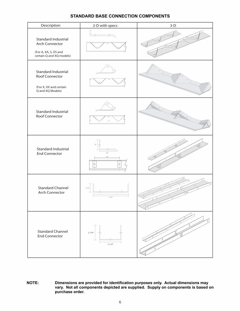
Description 2-D with specs 3-D
Standard Industrial Arch Connector
Standard Industrial End Connector
3"
4"
18"
Standard Channel Arch Connector
2-1/4"
7-1/2"
Standard Channel End Connector
2-7/8"
3-1/4"
Standard Industrial Roof Connector
(For X, XX and certainQ and XQ Models)
(For A, XA, S, XS andcertain Q and XQ models)
Standard Industrial Roof Connector
STANDARD BASE CONNECTION COMPONENTS NOTE: Dimensions are provided for identification purposes only. Actual dimensions may vary. Not all components depicted are supplied. Supply on components is based on purchase order.
7
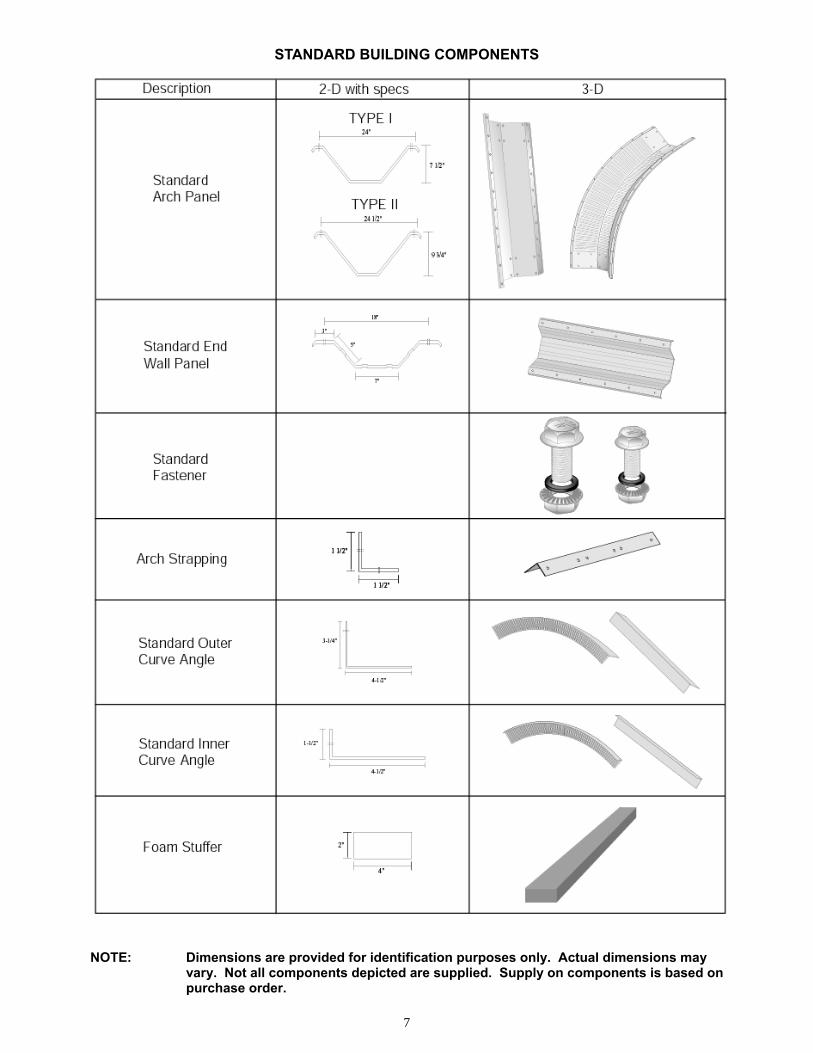
STANDARD BUILDING COMPONENTS NOTE: Dimensions are provided for identification purposes only. Actual dimensions may vary. Not all components depicted are supplied. Supply on components is based on purchase order.
8
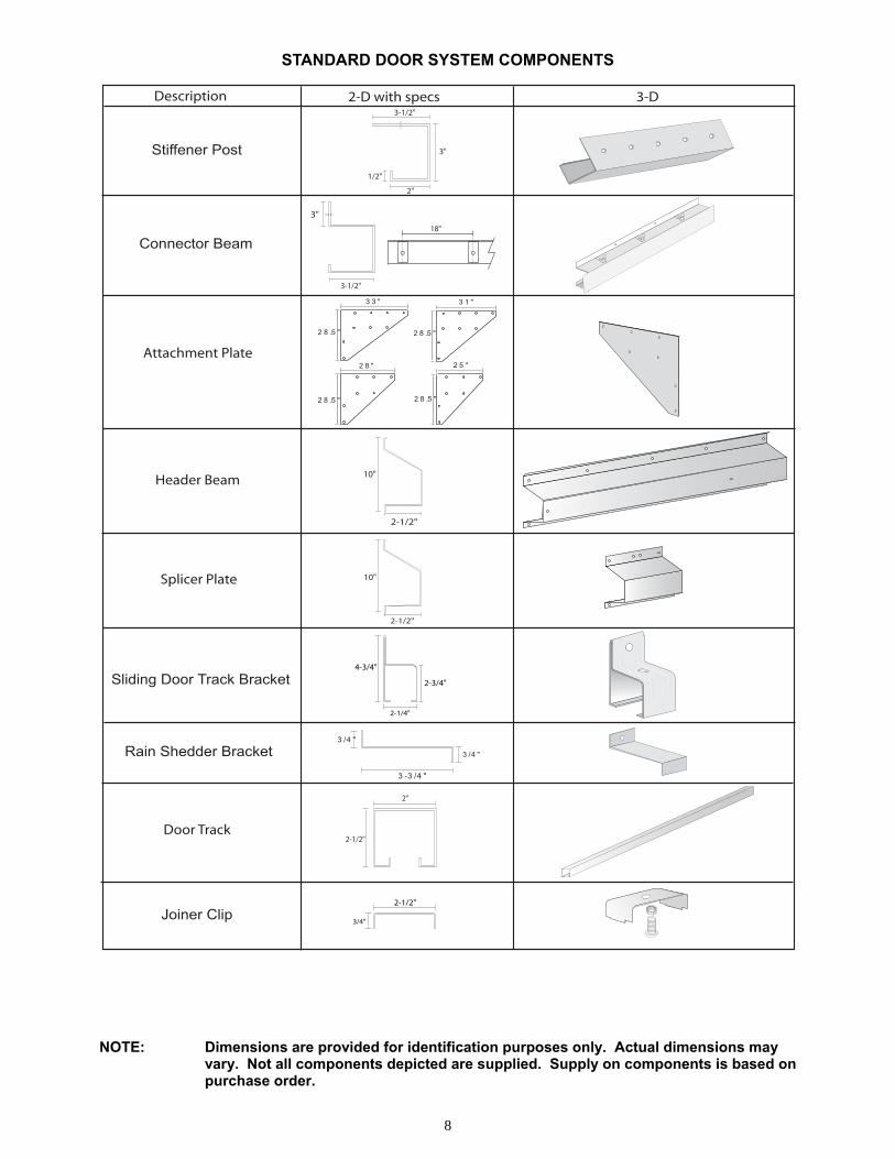
Description 2-D with specs 3-D
Joiner Clip
Sliding Door Track Bracket
Rain Shedder Bracket
4-3/4"
2-3/4"
2-1/4"
3 -3 /4 "
3 /4 "
3 /4 "
3-1/2"
3"
2"
1/2"
Stiffener Post
3"
3-1/2"
18"
Connector Beam
Attachment Plate
Header Beam 10"
2-1/2"
Splicer Plate 10"
2-1/2"
Door Track2-1/2"
2"
3 3 " 3 1 "
2 8 " 2 5 "
2 8 .5 "
2 8 .5 "
2 8 .5 "
2 8 .5 "
2-1/2"
3/4"
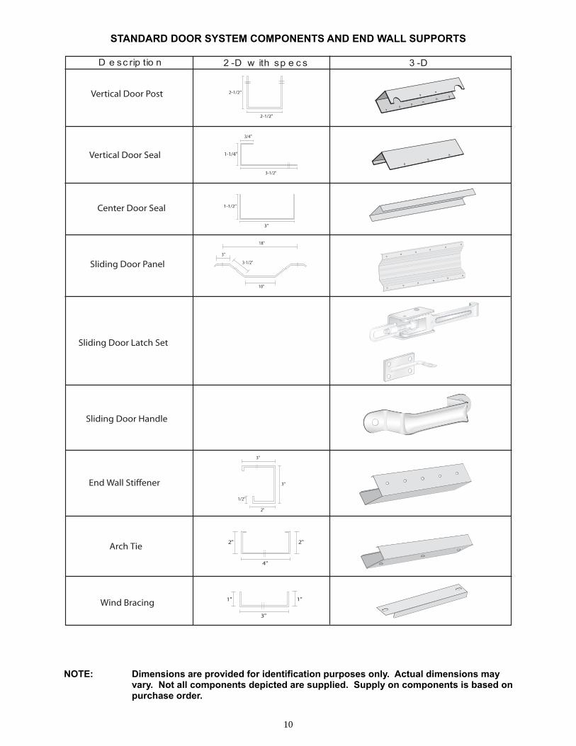
STANDARD DOOR SYSTEM COMPONENTS NOTE: Dimensions are provided for identification purposes only. Actual dimensions may vary. Not all components depicted are supplied. Supply on components is based on purchase order.
9
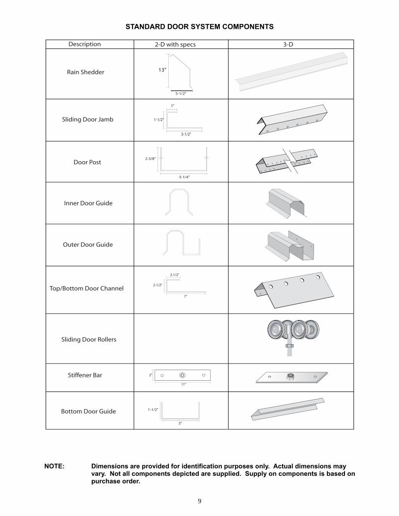
Inner Door Guide
Outer Door Guide
5-1/4"
2-3/8"Door Post
1"
1-1/2"
3-1/2"
Sliding Door Jamb
Description 2-D with specs 3-D
Sliding Door Rollers
Rain Shedder 13"
5-1/2"
Stiffener Bar11"
2"
2-1/2"
2-1/2"
7"
Top/Bottom Door Channel
1-1/2"
3"
Bottom Door Guide
STANDARD DOOR SYSTEM COMPONENTS
NOTE: Dimensions are provided for identification purposes only. Actual dimensions may vary. Not all components depicted are supplied. Supply on components is based on purchase order.
10
1" 1"
3"
Wind Bracing
3/4"
1-1/4"
3-1/2"
Vertical Door Seal
1-1/2"
3"
Center Door Seal
2-1/2"
2-1/2"Vertical Door Post
MMM
E EE
Sliding Door Latch Set
3"
10"
3-1/2"
18"
Sliding Door Panel
D e sc rip tio n 2 -D w ith sp e c s 3 -D
Sliding Door Handle
3"
3"
2"
1/2"
End Wall Stiffener
Arch Tie2" 2"
4"
STANDARD DOOR SYSTEM COMPONENTS AND END WALL SUPPORTS
NOTE: Dimensions are provided for identification purposes only. Actual dimensions may vary. Not all components depicted are supplied. Supply on components is based on purchase order.
11
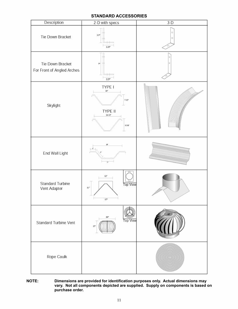
STANDARD ACCESSORIES NOTE: Dimensions are provided for identification purposes only. Actual dimensions may vary. Not all components depicted are supplied. Supply on components is based on purchase order.
12
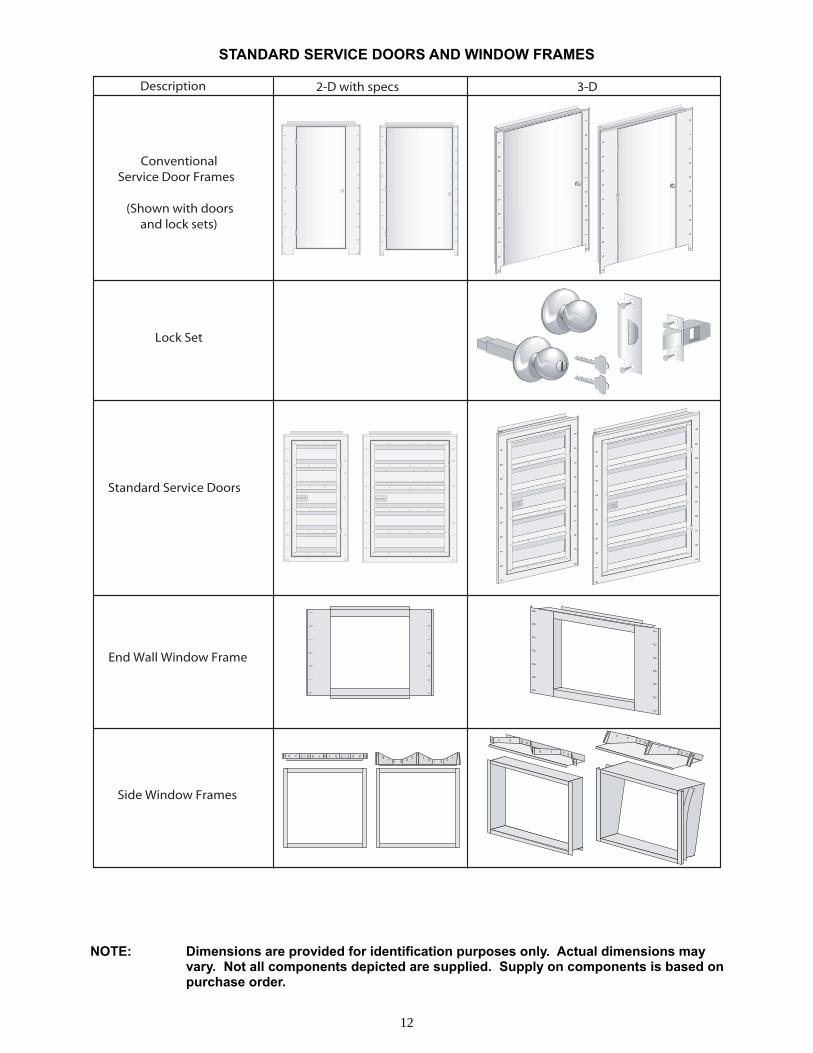
Description 2-D with specs 3-D
Conventional Service Door Frames
(Shown with doorsand lock sets)
Lock Set
Standard Service Doors
End Wall Window Frame
Side Window Frames
STANDARD SERVICE DOORS AND WINDOW FRAMES
NOTE: Dimensions are provided for identification purposes only. Actual dimensions may vary. Not all components depicted are supplied. Supply on components is based on purchase order.
13
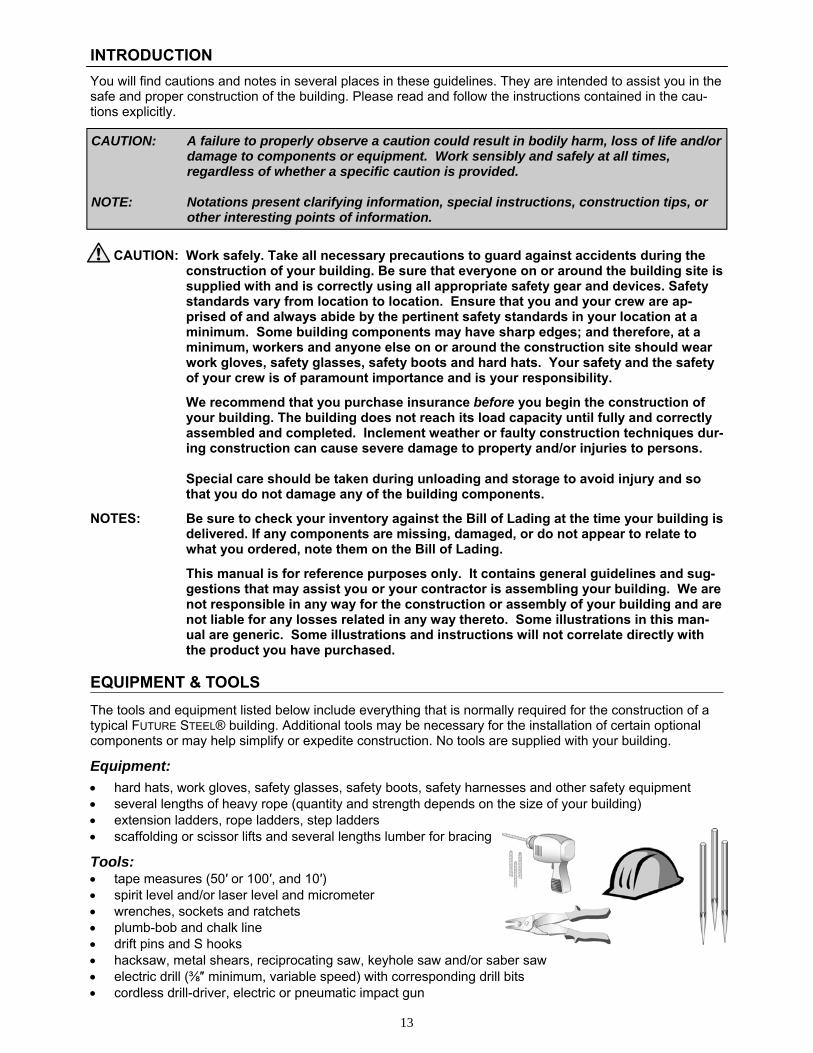
INTRODUCTION
You will find cautions and notes in several places in these guidelines. They are intended to assist you in the safe and proper construction of the building. Please read and follow the instructions contained in the cau-tions explicitly.
CAUTION: Work safely. Take all necessary precautions to guard against accidents during the construction of your building. Be sure that everyone on or around the building site is supplied with and is correctly using all appropriate safety gear and devices. Safety standards vary from location to location. Ensure that you and your crew are ap-prised of and always abide by the pertinent safety standards in your location at a minimum. Some building components may have sharp edges; and therefore, at a minimum, workers and anyone else on or around the construction site should wear work gloves, safety glasses, safety boots and hard hats. Your safety and the safety of your crew is of paramount importance and is your responsibility.
We recommend that you purchase insurance before you begin the construction of your building. The building does not reach its load capacity until fully and correctly assembled and completed. Inclement weather or faulty construction techniques dur-ing construction can cause severe damage to property and/or injuries to persons.
Special care should be taken during unloading and storage to avoid injury and so
that you do not damage any of the building components.
NOTES: Be sure to check your inventory against the Bill of Lading at the time your building is delivered. If any components are missing, damaged, or do not appear to relate to what you ordered, note them on the Bill of Lading.
This manual is for reference purposes only. It contains general guidelines and sug-
gestions that may assist you or your contractor is assembling your building. We are not responsible in any way for the construction or assembly of your building and are not liable for any losses related in any way thereto. Some illustrations in this man-ual are generic. Some illustrations and instructions will not correlate directly with the product you have purchased.
EQUIPMENT & TOOLS
The tools and equipment listed below include everything that is normally required for the construction of a typical FUTURE STEEL® building. Additional tools may be necessary for the installation of certain optional components or may help simplify or expedite construction. No tools are supplied with your building.
Equipment:
• hard hats, work gloves, safety glasses, safety boots, safety harnesses and other safety equipment • several lengths of heavy rope (quantity and strength depends on the size of your building) • extension ladders, rope ladders, step ladders • scaffolding or scissor lifts and several lengths lumber for bracing
Tools: • tape measures (50′ or 100′, and 10′) • spirit level and/or laser level and micrometer • wrenches, sockets and ratchets • plumb-bob and chalk line • drift pins and S hooks • hacksaw, metal shears, reciprocating saw, keyhole saw and/or saber saw • electric drill (⅜″ minimum, variable speed) with corresponding drill bits • cordless drill-driver, electric or pneumatic impact gun
CAUTION: A failure to properly observe a caution could result in bodily harm, loss of life and/or damage to components or equipment. Work sensibly and safely at all times, regardless of whether a specific caution is provided. NOTE: Notations present clarifying information, special instructions, construction tips, or other interesting points of information.
14
FOUNDATION, STRUCTURAL SUPPORTS & WALLS
Prior to receiving your building components, you should have received a set of blueprints. If you have re-ceived more than one set of blueprints, refer only to the most current blueprint. If you have not received, cannot locate, or do not understand your blueprint, DO NOT PROCEED. Contact our Technical Support and Engineering Services Department at (800) 387-2343.
Unless we have been advised that you are using a custom or pre-existing foundation, our blueprint typically provides you with the dimensions of the concrete footers and slab and the locations and specifications of anchor bolts and reinforcing steel for our foundation design, as well as acceptable soil conditions, concrete strength, etc. The foundation design depicted on the blueprint is a minimum design, since soil conditions and foundation requirements vary from site to site and may require increases to our design. If you wish to use our design, you should have it reviewed by a local engineer or building official to ensure that our design meets your local requirements and that your specific site meets the requirements of our design. If we have been advised that you are designing a custom foundation or using a pre-existing foun-dation, this will be noted on your blueprint. In such a case, our foundation design is simply for dimensional purposes and to indicate the location of your anchor bolts. We will also have supplied arch reactions, which you must provide to your engineer to confirm that your design or pre-existing foundation are adequate for your building.
Structural supports and walls are not normally necessary for our building. The exceptions to this norm are T, R, and M model buildings or variations of them. In such a case, the supports and/or walls will be de-picted on your blueprints. Unless we have specifically designed the supports or walls, we have provided reactions for the arches, which you must provide to a local engineer so that your supports or walls are prop-erly designed. If we have designed your supports or walls, we recommend that you have our design re-viewed by a local engineer to confirm local suitability. CAUTION: If you are using a foundation, structural supports or walls other than as specified on
your blueprint, you must have an engineer confirm your design and materials. If your purchase order and blueprint did not specifically state that you were using a custom foundation, your order was reviewed assuming the use of our own founda-tion design. In such a case, immediately contact our Technical Support and Engi-neering Services Department at (800) 387-2343 to confirm that your building compo-nents are suitable for a custom design and, if so, to obtain reactions for your engi-neer. DO NOT PROCEED WITH CONSTRUCTION.
Unless your blueprint expressly states that the foundation is to be supplied and de-signed by others, we have assumed that you will follow our foundation design. If you wish to use a design other than the one depicted on our blueprint, you must confirm with us that your building components are suitable for construction on your custom or pre-existing foundation. If your blueprint indicates that the foundation, structural steel or masonry walls are to be designed and/or supplied by others, you must provide the arch reactions to a local engineer to confirm the design of the structural supports or walls. We will not be responsible for any damages that may occur as a consequence of the construction of our building on a foundation or struc-tural supports that vary from our design.
If you will be following our suggested foundation design, have a local engineer or building authority ensure that our design meets local requirements and that your building site is suitable and meets our design criteria. Once our design and your site have been approved, be sure to follow all aspects of design including, without limitation, concrete grade and dimensions, concrete slab, steel reinforcements, an-chor bolts, tie-down brackets, grout, etc. as specified.
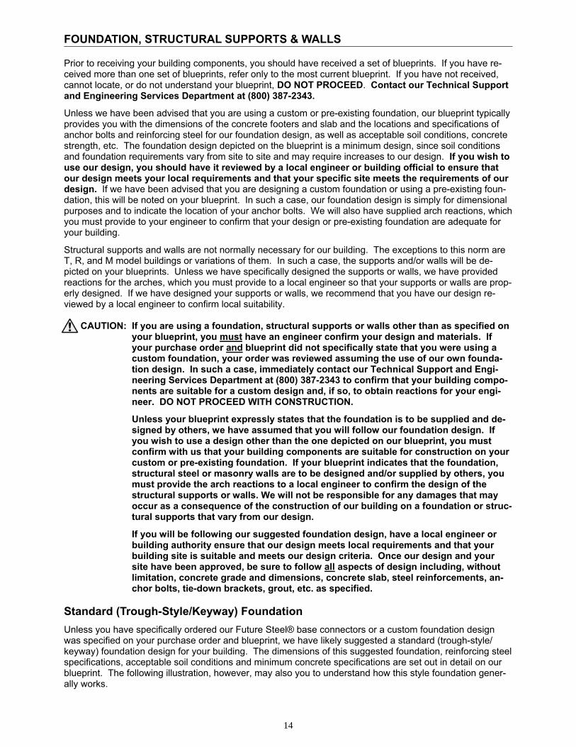
Standard (Trough-Style/Keyway) Foundation
Unless you have specifically ordered our Future Steel® base connectors or a custom foundation design was specified on your purchase order and blueprint, we have likely suggested a standard (trough-style/keyway) foundation design for your building. The dimensions of this suggested foundation, reinforcing steel specifications, acceptable soil conditions and minimum concrete specifications are set out in detail on our blueprint. The following illustration, however, may also you to understand how this style foundation gener-ally works.
15
Concrete
#6 @ 6’ Center to Center
6” x 6” Welded Wire
#3 @ 18” Center to Center
#4
FIGURE 1: CROSS SECTIONS OF TYPICAL STANDARD FOUNDATION
CAUTION: Refer to blueprint for specific dimensions and specifications. If you are using j- bolts, they must be installed at the locations specified on the blueprints before the concrete begins to set or cure. Anchor Bolts & Tie-down Brackets
After each arch is erected, it must be secured to the foundation with an anchor bolt and a tie-down bracket. The arches are anchored at each point where they overlap an adjacent arch and in the centre of the panels. The anchor bolts are set inside the trough along the length of the foundation. The specification and location of your anchor bolts and tie-down brackets is critical and is set out on your blueprints.
Future Steel® end wall panels must also be fastened to the foundation with an anchor bolt and a tie-down bracket. The brackets fasten on the interior side of the end wall panels, through bolt-holes field drilled through the valley of the panels. Refer to your blueprints for exact anchor bolt locations.
Anchor bolts and tie-down brackets are not supplied with your building unless they are specifically ordered. They are available for purchase as optional items, or can be purchased from a local building supply or hard-ware store. Tie down brackets can also be fabricated on-site. Refer to the blueprint for anchor-bolt and tie down bracket sizes and specifications. CAUTION: Although anchor bolts and tie-down brackets are not normally supplied with
your building, if you are using a keyway foundation design, they must be in stalled as specified on the blueprint. Anchor bolts are always required, even when our base connectors are being used. These items are necessary to secure your building to the foundation during and after construction and will help prevent the arches and end walls from being blown over or lifted out of the
foundation troughs by strong winds. They are also critical for the building to achieve its load capacity (as specified on your blueprints) after construction is complete. The following illustrations are for general reference only. Refer to the blueprints for specific sizes, specifications and locations of your anchor bolt and tie-down brackets.
16
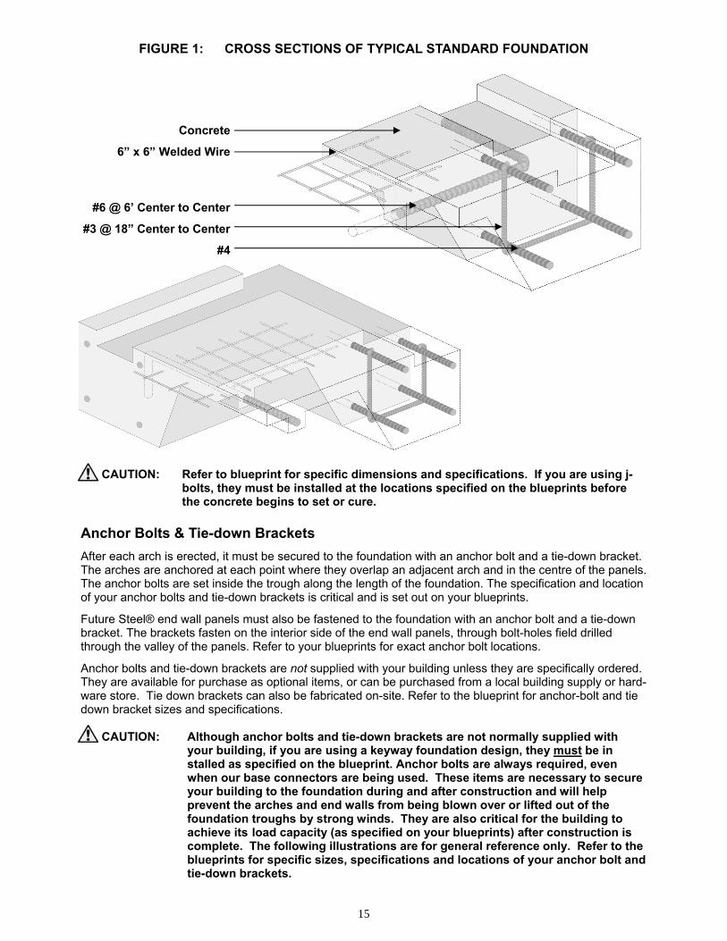
FIGURE 2: STANDARD FOUNDATION (WITHOUT END WALLS)
CAUTION: Refer to blueprint for specific dimensions and specifications. If you are using j- bolts, they must be installed at the locations specified on the blueprints before the concrete begins to set or cure.
FIGURE 3: STANDARD FOUNDATION (WITH END WALLS) CAUTION: Refer to blueprint for specific dimensions and specifications. If you are using j- bolts, they must be installed at the locations specified on the blueprints before the concrete begins to set or cure.

17
BUILDING INTERIOR
FIGURE 4: TYPICAL ANCHOR BOLTS AND TIE DOWN BRACKETS (ARCHES)
CAUTION: Tie-down brackets are not supplied unless they have been specifically ordered, but are
always required. If they have not been ordered, you must use an equivalent or supe-rior method of anchoring the building to the foundation.
NOTE: Please take note of the instructions in the above figure for proper tie-down bracket installation.
FIGURE 5: TYPICAL ANCHOR BOLTS AND TIE DOWN BRACKETS (END WALLS) CAUTION: Each arch and end wall panel must be anchored to the foundation. Refer to blue prints for specific sizes and specifications of anchor bolts. NOTE: Many customers prefer to use epoxy/expansion/wedge anchors which are installed after the concrete has cured as opposed to j-bolts or lag-bolts. Please refer to your blueprint for equivalent dimensions.
18
#4
#3 @ 18” Center to Center
6” x 6” Welded Wire
#6 @ 6’ Center to Center
Concrete
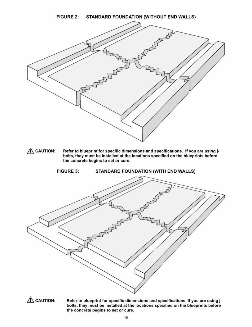
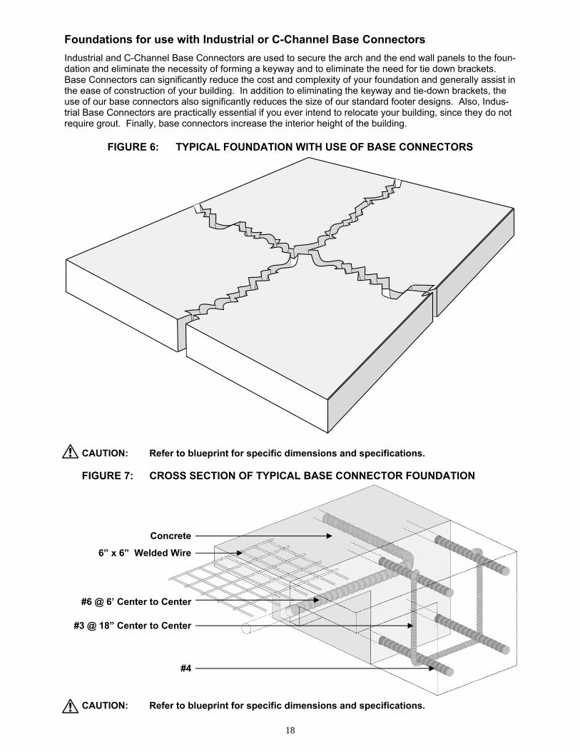
Foundations for use with Industrial or C-Channel Base Connectors
Industrial and C-Channel Base Connectors are used to secure the arch and the end wall panels to the foun-dation and eliminate the necessity of forming a keyway and to eliminate the need for tie down brackets. Base Connectors can significantly reduce the cost and complexity of your foundation and generally assist in the ease of construction of your building. In addition to eliminating the keyway and tie-down brackets, the use of our base connectors also significantly reduces the size of our standard footer designs. Also, Indus-trial Base Connectors are practically essential if you ever intend to relocate your building, since they do not require grout. Finally, base connectors increase the interior height of the building.
FIGURE 6: TYPICAL FOUNDATION WITH USE OF BASE CONNECTORS CAUTION: Refer to blueprint for specific dimensions and specifications. FIGURE 7: CROSS SECTION OF TYPICAL BASE CONNECTOR FOUNDATION CAUTION: Refer to blueprint for specific dimensions and specifications.
19
If you have not purchased base connectors but are interested in receiving further information about them, please do not proceed with the construction of your foundation until you have contacted your sales representative. For specifications and dimensions regarding our foundation design, including soil and concrete require-ments and reinforcing steel and anchor bolt specifications and locations, refer to the blueprint. Foundation Summary
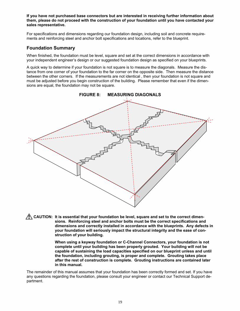
When finished, the foundation must be level, square and set at the correct dimensions in accordance with your independent engineer’s design or our suggested foundation design as specified on your blueprints.
A quick way to determine if your foundation is not square is to measure the diagonals. Measure the dis-tance from one corner of your foundation to the far corner on the opposite side. Then measure the distance between the other corners. If the measurements are not identical , then your foundation is not square and must be adjusted before you begin construction of the building. Please remember that even if the dimen-sions are equal, the foundation may not be square.
FIGURE 8: MEASURING DIAGONALS CAUTION: It is essential that your foundation be level, square and set to the correct dimen-
sions. Reinforcing steel and anchor bolts must be the correct specifications and dimensions and correctly installed in accordance with the blueprints. Any defects in your foundation will seriously impact the structural integrity and the ease of con-struction of your building.
When using a keyway foundation or C-Channel Connectors, your foundation is not complete until your building has been properly grouted. Your building will not be capable of sustaining the load capacities specified on our blueprint unless and until the foundation, including grouting, is proper and complete. Grouting takes place after the rest of construction is complete. Grouting instructions are contained later in this manual.
The remainder of this manual assumes that your foundation has been correctly formed and set. If you have any questions regarding the foundation, please consult your engineer or contact our Technical Support de-partment.
20
INDUSTRIAL AND C-CHANNEL BASE CONNECTORS
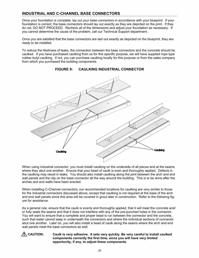
Once your foundation is complete, lay out your base connectors in accordance with your blueprint. If your foundation is correct, the base connectors should lay out exactly as they are depicted on the print. If they do not, DO NOT PROCEED. Recheck all of the dimensions and adjust your foundation as necessary. If you cannot determine the cause of the problem, call our Technical Support department. Once you are satisfied that the base connectors are laid out exactly as depicted on the blueprint, they are ready to be installed. To reduce the likeliness of leaks, the connection between the base connectors and the concrete should be caulked. If you have purchased caulking from us for this specific purpose, we will have supplied rope type rubber butyl caulking. If not, you can purchase caulking locally for this purpose or from the sales company from which you purchased the building components.
FIGURE 9: CAULKING INDUSTRIAL CONNECTOR When using industrial connector, you must install caulking on the underside of all pieces and at the seams where they abut one another. Ensure that your bead of caulk is even and thoroughly applied. Defects in the caulking may result in leaks. You should also install caulking along the joint between the arch and end wall panels and the clip on the base connector all the way around the building. This is to be done after the arches and end walls have been erected. When installing C-Channel connectors, our recommended locations for caulking are very similar to those for the Industrial connectors discussed above, except that caulking is not required at the base of the arch and end wall panels since this area will be covered in grout later in construction. Refer to the following fig-ure for assistance. As a general rule, ensure that the caulk is evenly and thoroughly applied, that it will meet the concrete and/or fully seals the seams and that it does not interfere with any of the pre-punched holes in the connector. You will want to ensure that a complete and proper bead is run between the connector and the concrete, such that water cannot seep in underneath the connectors and where the individual sections of connector abut one another. Later on, you will also install a bead of caulk along the seams where the arch and end wall panels meet the base connectors as well. CAUTION: Caulk is very adhesive. It sets very quickly. Be very careful to install caulked components correctly the first time, since you will have very limited opportunity, if any, to adjust these components.
21
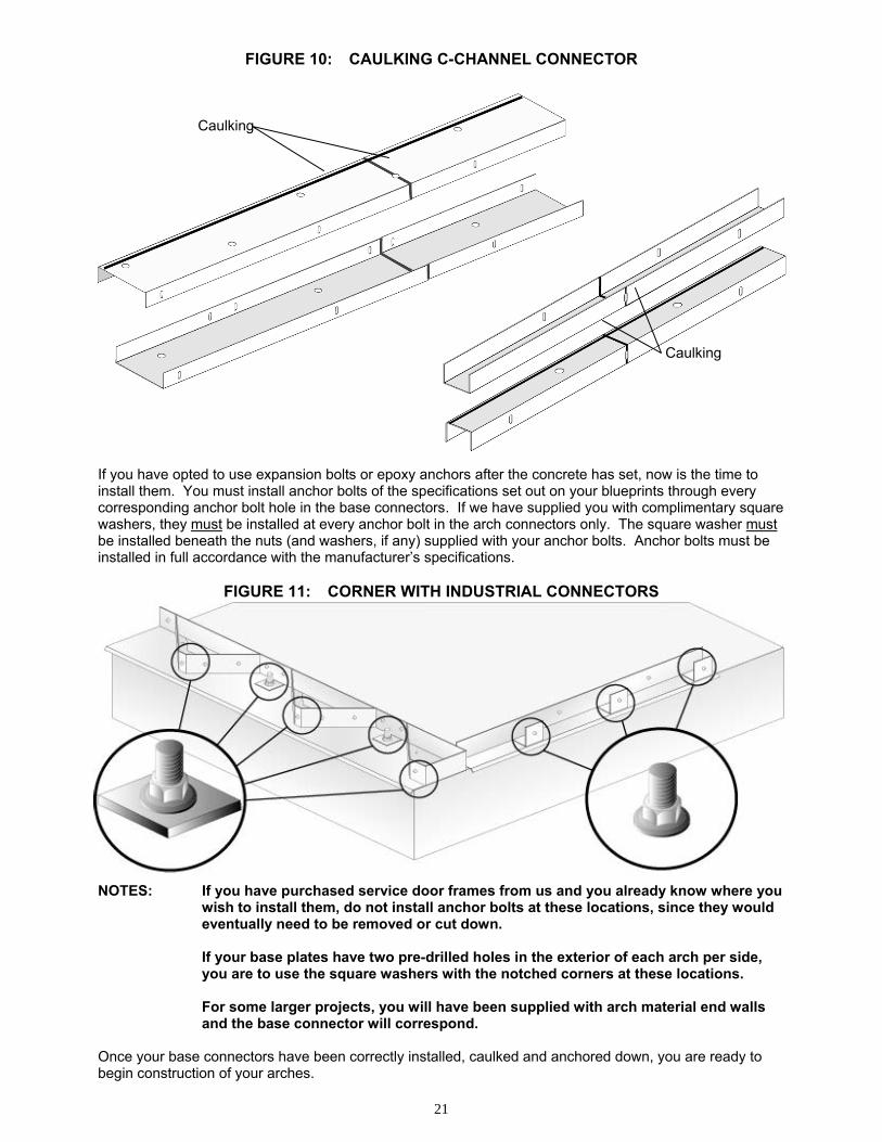
FIGURE 10: CAULKING C-CHANNEL CONNECTOR If you have opted to use expansion bolts or epoxy anchors after the concrete has set, now is the time to install them. You must install anchor bolts of the specifications set out on your blueprints through every corresponding anchor bolt hole in the base connectors. If we have supplied you with complimentary square washers, they must be installed at every anchor bolt in the arch connectors only. The square washer must be installed beneath the nuts (and washers, if any) supplied with your anchor bolts. Anchor bolts must be installed in full accordance with the manufacturer’s specifications.
FIGURE 11: CORNER WITH INDUSTRIAL CONNECTORS NOTES: If you have purchased service door frames from us and you already know where you wish to install them, do not install anchor bolts at these locations, since they would eventually need to be removed or cut down. If your base plates have two pre-drilled holes in the exterior of each arch per side, you are to use the square washers with the notched corners at these locations. For some larger projects, you will have been supplied with arch material end walls and the base connector will correspond. Once your base connectors have been correctly installed, caulked and anchored down, you are ready to begin construction of your arches.
Caulking
Caulking
22
24"
7.5"
7.5"
24.5"
4.75"
9.75"
TYPE I TYPE II
ARCHES
The arches of your FUTURE STEEL® building are the main structural elements of the building, acting as the side walls, roof and structural supports of the structure. Each arch should be assembled on the ground, raised and set into place in the foundation or on the base connectors, and then fastened to an adjacent arch. Check the arches on a continual basis to make certain they are plumb, square and the correct width, height and length as specified on your blueprints. Getting Started
Confirm the following before beginning construction: • That the work area is clear and safe • That your foundation is level, square and constructed to the correct dimensions • That you have all the necessary tools, equipment and manpower • That everyone at or around the site is correctly using hard-hats, safety boots, safety glasses, work
gloves and all other appropriate safety equipment and that everyone working at heights are also using harnesses
• That you have an adequate source of electricity for your power equipment • That you and your crew have read through and understand these guidelines If any of the above is not the case, please do not proceed until the problem has been rectified. Layout & Preparation of the Work Area
There should be two large, clear areas at each end of your building site – the clear distance should be at least 1.5 times the height of your building, and there should be at least ten feet of clearance along each side of the foundation.
If only one end wall with an opening has been purchased from us, you should start construction at the end of the building where that opening will be constructed.
Gather your crew. Make certain they understand who is giving the orders. Tell them you want the work to proceed smoothly and correctly. If any questions arise, ask before proceeding. Above all, you want every-one to work safely. Stress the importance of safety equipment and make certain that it is used cor-rectly at all times. NOTE: If possible, erect the arches opposite to the direction of the prevailing winds in your
area – from the leeward toward the windward (typically south to north). This will help to weatherproof your building because the overlap of the arches will then run in the same direction as the local prevailing winds and more easily shed driving wind, rain and snow.
Panel Types and Anatomy
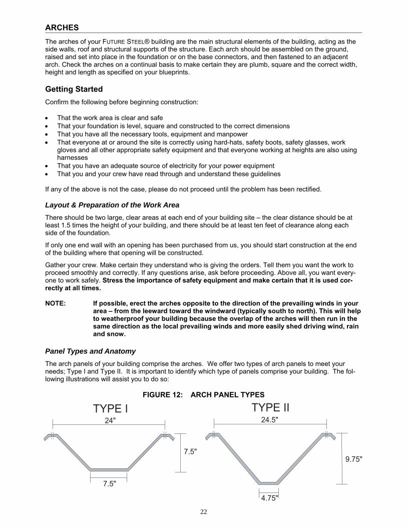
The arch panels of your building comprise the arches. We offer two types of arch panels to meet your needs; Type I and Type II. It is important to identify which type of panels comprise your building. The fol-lowing illustrations will assist you to do so:
FIGURE 12: ARCH PANEL TYPES
23
NOTE: In these guidelines, the arch panel dimensions are rounded. A precise measurement of the panels may indicate a minor deviation from the stated dimension.
Arch Models
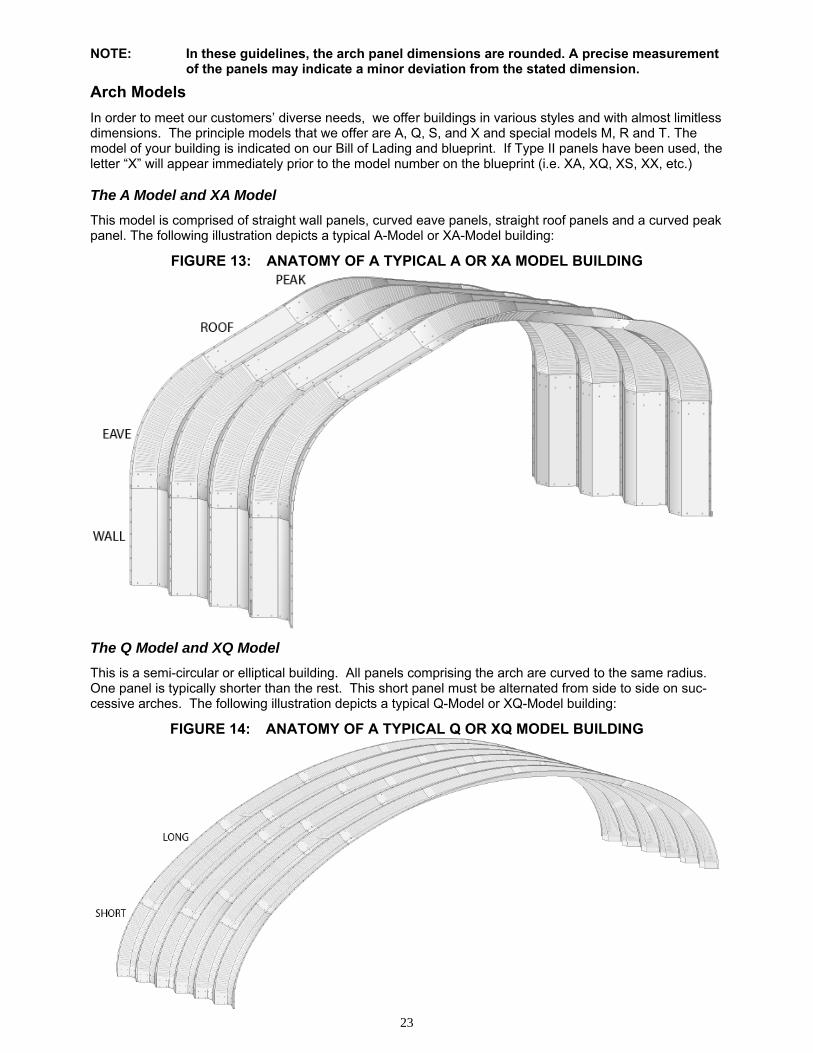
In order to meet our customers’ diverse needs, we offer buildings in various styles and with almost limitless dimensions. The principle models that we offer are A, Q, S, and X and special models M, R and T. The model of your building is indicated on our Bill of Lading and blueprint. If Type II panels have been used, the letter “X” will appear immediately prior to the model number on the blueprint (i.e. XA, XQ, XS, XX, etc.) The A Model and XA Model
This model is comprised of straight wall panels, curved eave panels, straight roof panels and a curved peak panel. The following illustration depicts a typical A-Model or XA-Model building:
FIGURE 13: ANATOMY OF A TYPICAL A OR XA MODEL BUILDING The Q Model and XQ Model
This is a semi-circular or elliptical building. All panels comprising the arch are curved to the same radius. One panel is typically shorter than the rest. This short panel must be alternated from side to side on suc-cessive arches. The following illustration depicts a typical Q-Model or XQ-Model building:
FIGURE 14: ANATOMY OF A TYPICAL Q OR XQ MODEL BUILDING
24
The R Model and XR Model
This special model is typically used for roofing applications and is normally, but not always, based on the same design principles as Q Model buildings. It is normally installed on concrete walls or a structural steel frame that either we have designed for you, as depicted on your blueprint, or as has been designed by your independent engineer using the arch reactions provided on the blueprint. The S Model and XS Model
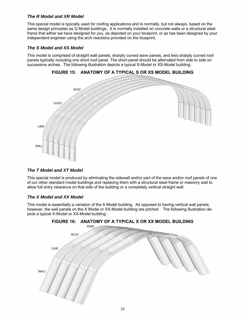
This model is comprised of straight wall panels, sharply curved eave panels, and less sharply curved roof panels typically including one short roof panel. The short panel should be alternated from side to side on successive arches. The following illustration depicts a typical S-Model or XS-Model building:
FIGURE 15: ANATOMY OF A TYPICAL S OR XS MODEL BUILDING The T Model and XT Model
This special model is produced by eliminating the sidewall and/or part of the eave and/or roof panels of one of our other standard model buildings and replacing them with a structural steel frame or masonry wall to allow full entry clearance on that side of the building or a completely vertical straight wall. The X Model and XX Model
This model is essentially a variation of the A Model building. As opposed to having vertical wall panels, however, the wall panels on the X Model or XX-Model building are pitched. The following illustration de-picts a typical X-Model or XX-Model building:
FIGURE 16: ANATOMY OF A TYPICAL X OR XX MODEL BUILDING
25
GAUGE THICKNESS 22 0.03” / 0.8 mm 20 0.04” / 1.0 mm 18 0.05” / 1.3 mm 16 0.06” / 1.5 mm 14 0.07” / 1.9 mm
12 (Galvanized) 0.10” / 2.7 mm
Assembling the Arches
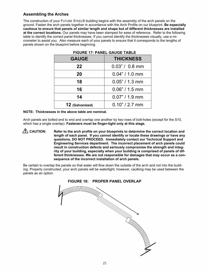
The construction of your FUTURE STEEL® building begins with the assembly of the arch panels on the ground. Fasten the arch panels together in accordance with the Arch Profile on our blueprint. Be especially cautious to ensure that panels of similar length and shape but of different thicknesses are installed at the correct locations. Our panels may have been stamped for ease of reference. Refer to the following table to identify the correct panel thicknesses. If you cannot identify the thicknesses visually, use a mi-crometer to assist you. Also measure each of your panels to ensure that it corresponds to the lengths of panels shown on the blueprint before beginning.
FIGURE 17: PANEL GAUGE TABLE NOTE: Thicknesses in the above table are nominal. Arch panels are bolted end to end and overlap one another by two rows of bolt-holes (except for the S10, which has a single overlap). Fasteners must be finger-tight only at this stage.
CAUTION: Refer to the arch profile on your blueprints to determine the correct location and length of each panel. If you cannot identify or locate these drawings or have any questions, DO NOT PROCEED. Immediately contact our Technical Support and Engineering Services department. The incorrect placement of arch panels could result in construction defects and seriously compromise the strength and integ-rity of your building, especially when your building is comprised of panels of dif-ferent thicknesses. We are not responsible for damages that may occur as a con-sequence of the incorrect installation of arch panels.
Be certain to overlap the panels so that water will flow down the outside of the arch and not into the build-ing. Properly constructed, your arch panels will be watertight, however, caulking may be used between the panels as an option.
FIGURE 18: PROPER PANEL OVERLAP
26
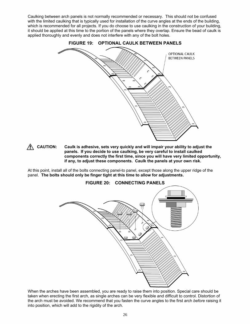
Caulking between arch panels is not normally recommended or necessary. This should not be confused with the limited caulking that is typically used for installation of the curve angles at the ends of the building, which is recommended for all projects. If you do choose to use caulking in the construction of your building, it should be applied at this time to the portion of the panels where they overlap. Ensure the bead of caulk is applied thoroughly and evenly and does not interfere with any of the bolt holes.
FIGURE 19: OPTIONAL CAULK BETWEEN PANELS
CAUTION: Caulk is adhesive, sets very quickly and will impair your ability to adjust the panels. If you decide to use caulking, be very careful to install caulked
components correctly the first time, since you will have very limited opportunity, if any, to adjust these components. Caulk the panels at your own risk. At this point, install all of the bolts connecting panel-to panel, except those along the upper ridge of the panel. The bolts should only be finger tight at this time to allow for adjustments.
FIGURE 20: CONNECTING PANELS When the arches have been assembled, you are ready to raise them into position. Special care should be taken when erecting the first arch, as single arches can be very flexible and difficult to control. Distortion of the arch must be avoided. We recommend that you fasten the curve angles to the first arch before raising it into position, which will add to the rigidity of the arch.
27
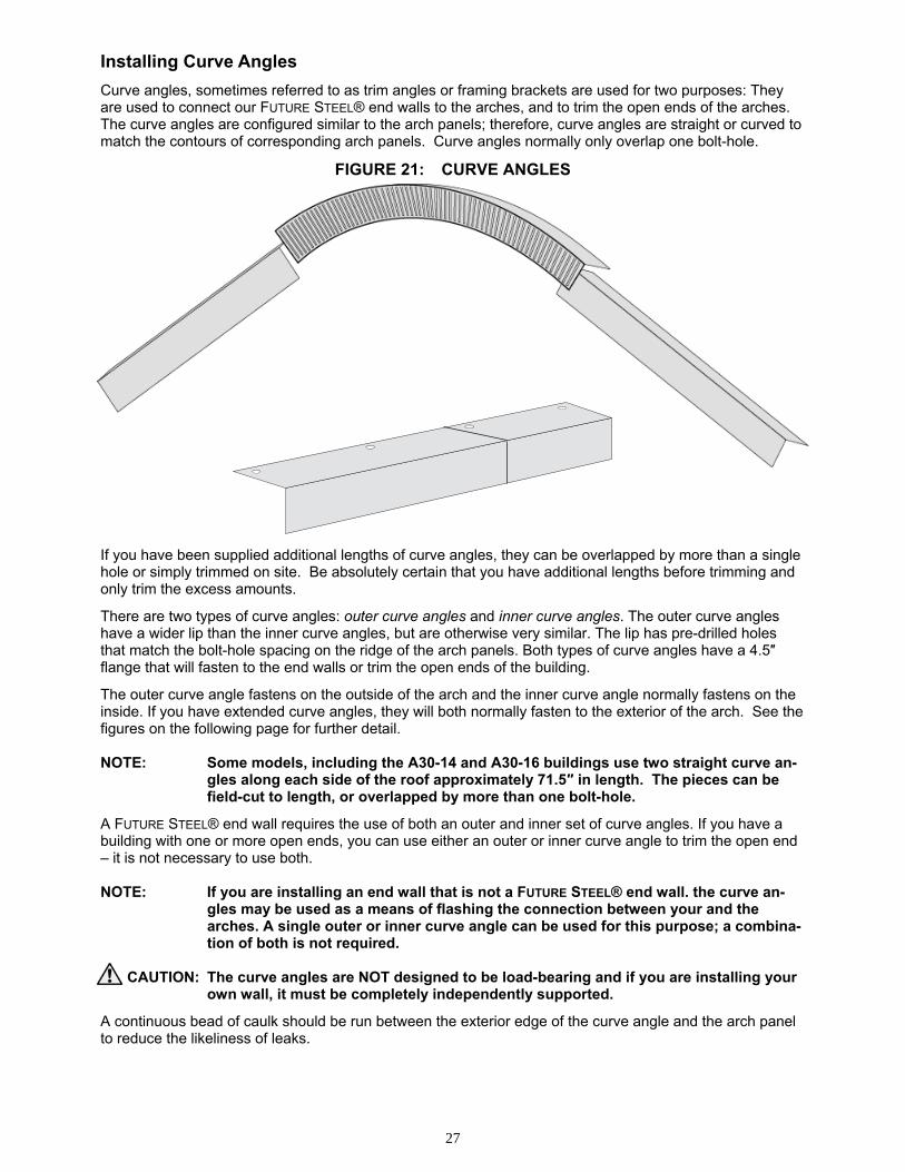
Installing Curve Angles
Curve angles, sometimes referred to as trim angles or framing brackets are used for two purposes: They are used to connect our FUTURE STEEL® end walls to the arches, and to trim the open ends of the arches. The curve angles are configured similar to the arch panels; therefore, curve angles are straight or curved to match the contours of corresponding arch panels. Curve angles normally only overlap one bolt-hole.
FIGURE 21: CURVE ANGLES
If you have been supplied additional lengths of curve angles, they can be overlapped by more than a single hole or simply trimmed on site. Be absolutely certain that you have additional lengths before trimming and only trim the excess amounts.
There are two types of curve angles: outer curve angles and inner curve angles. The outer curve angles have a wider lip than the inner curve angles, but are otherwise very similar. The lip has pre-drilled holes that match the bolt-hole spacing on the ridge of the arch panels. Both types of curve angles have a 4.5″ flange that will fasten to the end walls or trim the open ends of the building.
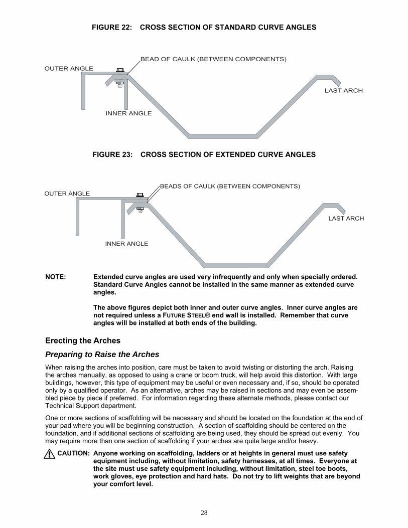
The outer curve angle fastens on the outside of the arch and the inner curve angle normally fastens on the inside. If you have extended curve angles, they will both normally fasten to the exterior of the arch. See the figures on the following page for further detail. NOTE: Some models, including the A30-14 and A30-16 buildings use two straight curve an-
gles along each side of the roof approximately 71.5″ in length. The pieces can be field-cut to length, or overlapped by more than one bolt-hole.
A FUTURE STEEL® end wall requires the use of both an outer and inner set of curve angles. If you have a building with one or more open ends, you can use either an outer or inner curve angle to trim the open end – it is not necessary to use both. NOTE: If you are installing an end wall that is not a FUTURE STEEL® end wall. the curve an-
gles may be used as a means of flashing the connection between your and the arches. A single outer or inner curve angle can be used for this purpose; a combina-tion of both is not required.
CAUTION: The curve angles are NOT designed to be load-bearing and if you are installing your
own wall, it must be completely independently supported.
A continuous bead of caulk should be run between the exterior edge of the curve angle and the arch panel to reduce the likeliness of leaks.
28
INNER ANGLE
LAST ARCH
BEADS OF CAULK (BETWEEN COMPONENTS)OUTER ANGLE
OUTER ANGLE
INNER ANGLE
LAST ARCH
BEAD OF CAULK (BETWEEN COMPONENTS)
FIGURE 22: CROSS SECTION OF STANDARD CURVE ANGLES
FIGURE 23: CROSS SECTION OF EXTENDED CURVE ANGLES
NOTE: Extended curve angles are used very infrequently and only when specially ordered. Standard Curve Angles cannot be installed in the same manner as extended curve angles. The above figures depict both inner and outer curve angles. Inner curve angles are not required unless a FUTURE STEEL® end wall is installed. Remember that curve angles will be installed at both ends of the building. Erecting the Arches
Preparing to Raise the Arches
When raising the arches into position, care must be taken to avoid twisting or distorting the arch. Raising the arches manually, as opposed to using a crane or boom truck, will help avoid this distortion. With large buildings, however, this type of equipment may be useful or even necessary and, if so, should be operated only by a qualified operator. As an alternative, arches may be raised in sections and may even be assem-bled piece by piece if preferred. For information regarding these alternate methods, please contact our Technical Support department.
One or more sections of scaffolding will be necessary and should be located on the foundation at the end of your pad where you will be beginning construction. A section of scaffolding should be centered on the foundation, and if additional sections of scaffolding are being used, they should be spread out evenly. You may require more than one section of scaffolding if your arches are quite large and/or heavy.
CAUTION: Anyone working on scaffolding, ladders or at heights in general must use safety equipment including, without limitation, safety harnesses, at all times. Everyone at the site must use safety equipment including, without limitation, steel toe boots, work gloves, eye protection and hard hats. Do not try to lift weights that are beyond your comfort level.
29
Raising the First Arch
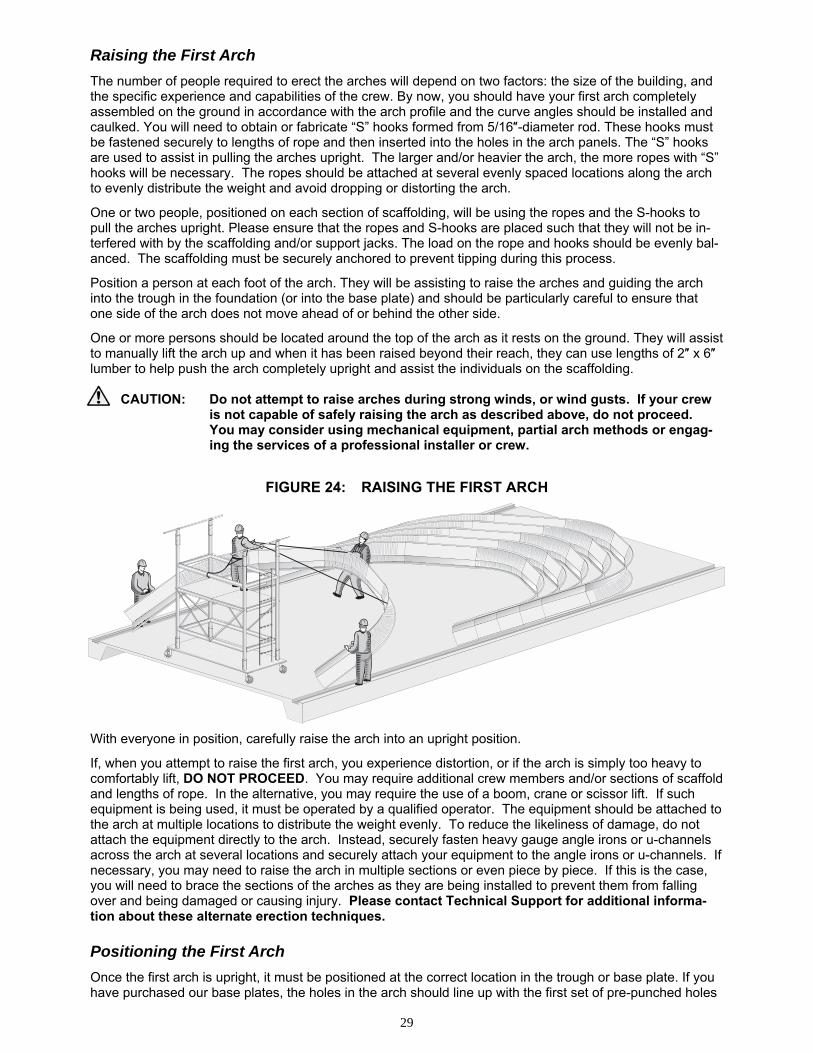
The number of people required to erect the arches will depend on two factors: the size of the building, and the specific experience and capabilities of the crew. By now, you should have your first arch completely assembled on the ground in accordance with the arch profile and the curve angles should be installed and caulked. You will need to obtain or fabricate “S” hooks formed from 5/16″-diameter rod. These hooks must be fastened securely to lengths of rope and then inserted into the holes in the arch panels. The “S” hooks are used to assist in pulling the arches upright. The larger and/or heavier the arch, the more ropes with “S” hooks will be necessary. The ropes should be attached at several evenly spaced locations along the arch to evenly distribute the weight and avoid dropping or distorting the arch.
One or two people, positioned on each section of scaffolding, will be using the ropes and the S-hooks to pull the arches upright. Please ensure that the ropes and S-hooks are placed such that they will not be in-terfered with by the scaffolding and/or support jacks. The load on the rope and hooks should be evenly bal-anced. The scaffolding must be securely anchored to prevent tipping during this process.
Position a person at each foot of the arch. They will be assisting to raise the arches and guiding the arch into the trough in the foundation (or into the base plate) and should be particularly careful to ensure that one side of the arch does not move ahead of or behind the other side.
One or more persons should be located around the top of the arch as it rests on the ground. They will assist to manually lift the arch up and when it has been raised beyond their reach, they can use lengths of 2″ x 6″ lumber to help push the arch completely upright and assist the individuals on the scaffolding.
CAUTION: Do not attempt to raise arches during strong winds, or wind gusts. If your crew is not capable of safely raising the arch as described above, do not proceed. You may consider using mechanical equipment, partial arch methods or engag-ing the services of a professional installer or crew.
FIGURE 24: RAISING THE FIRST ARCH
With everyone in position, carefully raise the arch into an upright position.
If, when you attempt to raise the first arch, you experience distortion, or if the arch is simply too heavy to comfortably lift, DO NOT PROCEED. You may require additional crew members and/or sections of scaffold and lengths of rope. In the alternative, you may require the use of a boom, crane or scissor lift. If such equipment is being used, it must be operated by a qualified operator. The equipment should be attached to the arch at multiple locations to distribute the weight evenly. To reduce the likeliness of damage, do not attach the equipment directly to the arch. Instead, securely fasten heavy gauge angle irons or u-channels across the arch at several locations and securely attach your equipment to the angle irons or u-channels. If necessary, you may need to raise the arch in multiple sections or even piece by piece. If this is the case, you will need to brace the sections of the arches as they are being installed to prevent them from falling over and being damaged or causing injury. Please contact Technical Support for additional informa-tion about these alternate erection techniques. Positioning the First Arch
Once the first arch is upright, it must be positioned at the correct location in the trough or base plate. If you have purchased our base plates, the holes in the arch should line up with the first set of pre-punched holes
30
BEAD OF CAULK
in the plates. Please refer to our blueprint or your local engineer’s design to determine the exact location of the first arch in relation to the foundation. Securing the First Arch
After the first arch has been set into position it should be securely tied-off to support jacks on the scaffold-ing, and to stakes driven into the ground. This will help provide a secure anchoring point from which to con-tinue the erection of the arches. Brace the arch so that the walls are plumb and the arch is set at the correct height. Raising the Rest of the Arches
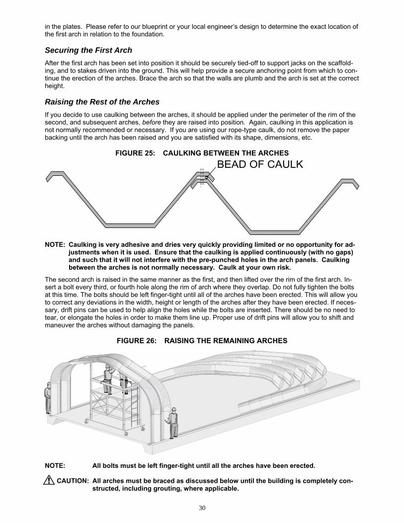
If you decide to use caulking between the arches, it should be applied under the perimeter of the rim of the second, and subsequent arches, before they are raised into position. Again, caulking in this application is not normally recommended or necessary. If you are using our rope-type caulk, do not remove the paper backing until the arch has been raised and you are satisfied with its shape, dimensions, etc.
FIGURE 25: CAULKING BETWEEN THE ARCHES
NOTE: Caulking is very adhesive and dries very quickly providing limited or no opportunity for ad-justments when it is used. Ensure that the caulking is applied continuously (with no gaps) and such that it will not interfere with the pre-punched holes in the arch panels. Caulking between the arches is not normally necessary. Caulk at your own risk.
The second arch is raised in the same manner as the first, and then lifted over the rim of the first arch. In-sert a bolt every third, or fourth hole along the rim of arch where they overlap. Do not fully tighten the bolts at this time. The bolts should be left finger-tight until all of the arches have been erected. This will allow you to correct any deviations in the width, height or length of the arches after they have been erected. If neces-sary, drift pins can be used to help align the holes while the bolts are inserted. There should be no need to tear, or elongate the holes in order to make them line up. Proper use of drift pins will allow you to shift and maneuver the arches without damaging the panels.
FIGURE 26: RAISING THE REMAINING ARCHES
NOTE: All bolts must be left finger-tight until all the arches have been erected.
CAUTION: All arches must be braced as discussed below until the building is completely con-structed, including grouting, where applicable.
31
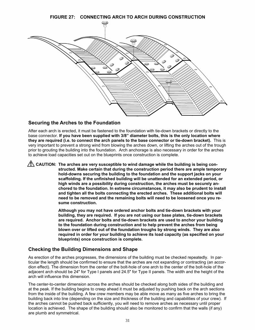
FIGURE 27: CONNECTING ARCH TO ARCH DURING CONSTRUCTION
Securing the Arches to the Foundation
After each arch is erected, it must be fastened to the foundation with tie-down brackets or directly to the base connector. If you have been supplied with 3/8” diameter bolts, this is the only location where they are required (i.e. to connect the arch panels to the base connector or tie-down bracket). This is very important to prevent a strong wind from blowing the arches down, or lifting the arches out of the trough prior to grouting the building into the foundation. Arch anchorage is also necessary in order for the arches to achieve load capacities set out on the blueprints once construction is complete.
CAUTION: The arches are very susceptible to wind damage while the building is being con-structed. Make certain that during the construction period there are ample temporary hold-downs securing the building to the foundation and the support jacks on your scaffolding. If the unfinished building will be unattended for an extended period, or high winds are a possibility during construction, the arches must be securely an-chored to the foundation. In extreme circumstances, it may also be prudent to install and tighten all the bolts connecting the erected arches. These additional bolts will need to be removed and the remaining bolts will need to be loosened once you re-sume construction.
Although you may not have ordered anchor bolts and tie-down brackets with your building, they are required. If you are not using our base plates, tie-down brackets are required. Anchor bolts and tie-down brackets are used to anchor your building to the foundation during construction and to help prevent the arches from being blown over or lifted out of the foundation troughs by strong winds. They are also required in order for your building to achieve its load capacity (as specified on your blueprints) once construction is complete.
Checking the Building Dimensions and Shape
As erection of the arches progresses, the dimensions of the building must be checked repeatedly. In par-ticular the length should be confirmed to ensure that the arches are not expanding or contracting (an accor-dion effect). The dimension from the center of the bolt-hole of one arch to the center of the bolt-hole of the adjacent arch should be 24″ for Type I panels and 24.5″ for Type II panels. The width and the height of the arch will influence this dimension.
The center-to-center dimension across the arches should be checked along both sides of the building and at the peak. If the building begins to creep ahead it must be adjusted by pushing back on the arch sections from the inside of the building. A few crew members may be able move as many as five arches to bring the building back into line (depending on the size and thickness of the building and capabilities of your crew). If the arches cannot be pushed back sufficiently, you will need to remove arches as necessary until proper location is achieved. The shape of the building should also be monitored to confirm that the walls (if any) are plumb and symmetrical.
32
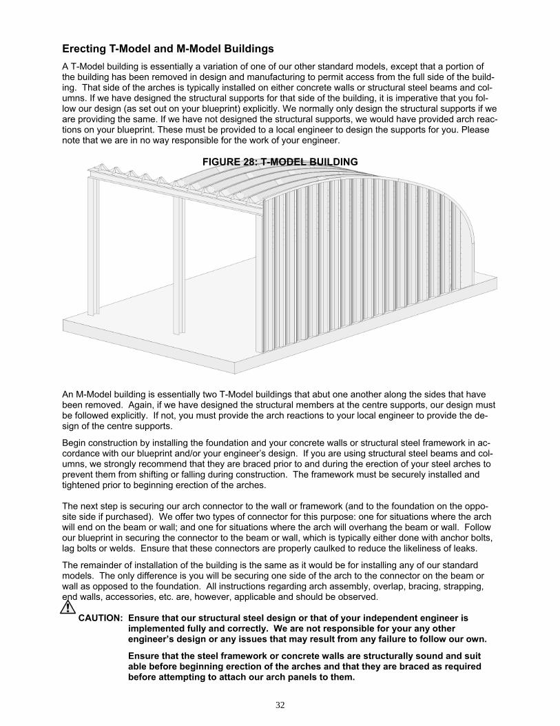
Erecting T-Model and M-Model Buildings
A T-Model building is essentially a variation of one of our other standard models, except that a portion of the building has been removed in design and manufacturing to permit access from the full side of the build-ing. That side of the arches is typically installed on either concrete walls or structural steel beams and col-umns. If we have designed the structural supports for that side of the building, it is imperative that you fol-low our design (as set out on your blueprint) explicitly. We normally only design the structural supports if we are providing the same. If we have not designed the structural supports, we would have provided arch reac-tions on your blueprint. These must be provided to a local engineer to design the supports for you. Please note that we are in no way responsible for the work of your engineer.
FIGURE 28: T-MODEL BUILDING An M-Model building is essentially two T-Model buildings that abut one another along the sides that have been removed. Again, if we have designed the structural members at the centre supports, our design must be followed explicitly. If not, you must provide the arch reactions to your local engineer to provide the de-sign of the centre supports.
Begin construction by installing the foundation and your concrete walls or structural steel framework in ac-cordance with our blueprint and/or your engineer’s design. If you are using structural steel beams and col-umns, we strongly recommend that they are braced prior to and during the erection of your steel arches to prevent them from shifting or falling during construction. The framework must be securely installed and tightened prior to beginning erection of the arches. The next step is securing our arch connector to the wall or framework (and to the foundation on the oppo-site side if purchased). We offer two types of connector for this purpose: one for situations where the arch will end on the beam or wall; and one for situations where the arch will overhang the beam or wall. Follow our blueprint in securing the connector to the beam or wall, which is typically either done with anchor bolts, lag bolts or welds. Ensure that these connectors are properly caulked to reduce the likeliness of leaks.
The remainder of installation of the building is the same as it would be for installing any of our standard models. The only difference is you will be securing one side of the arch to the connector on the beam or wall as opposed to the foundation. All instructions regarding arch assembly, overlap, bracing, strapping, end walls, accessories, etc. are, however, applicable and should be observed.
CAUTION: Ensure that our structural steel design or that of your independent engineer is implemented fully and correctly. We are not responsible for your any other
engineer’s design or any issues that may result from any failure to follow our own.
Ensure that the steel framework or concrete walls are structurally sound and suit able before beginning erection of the arches and that they are braced as required before attempting to attach our arch panels to them.
33
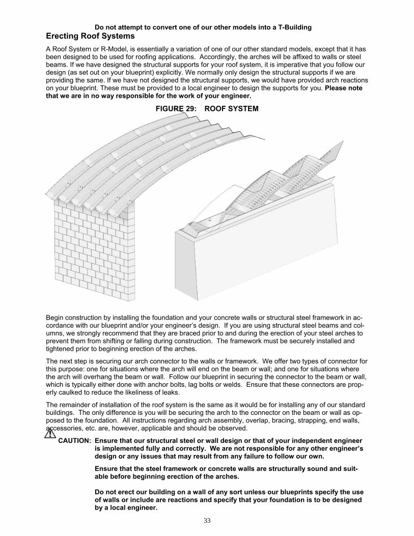
Do not attempt to convert one of our other models into a T-Building Erecting Roof Systems
A Roof System or R-Model, is essentially a variation of one of our other standard models, except that it has been designed to be used for roofing applications. Accordingly, the arches will be affixed to walls or steel beams. If we have designed the structural supports for your roof system, it is imperative that you follow our design (as set out on your blueprint) explicitly. We normally only design the structural supports if we are providing the same. If we have not designed the structural supports, we would have provided arch reactions on your blueprint. These must be provided to a local engineer to design the supports for you. Please note that we are in no way responsible for the work of your engineer.
FIGURE 29: ROOF SYSTEM
Begin construction by installing the foundation and your concrete walls or structural steel framework in ac-cordance with our blueprint and/or your engineer’s design. If you are using structural steel beams and col-umns, we strongly recommend that they are braced prior to and during the erection of your steel arches to prevent them from shifting or falling during construction. The framework must be securely installed and tightened prior to beginning erection of the arches.
The next step is securing our arch connector to the walls or framework. We offer two types of connector for this purpose: one for situations where the arch will end on the beam or wall; and one for situations where the arch will overhang the beam or wall. Follow our blueprint in securing the connector to the beam or wall, which is typically either done with anchor bolts, lag bolts or welds. Ensure that these connectors are prop-erly caulked to reduce the likeliness of leaks.
The remainder of installation of the roof system is the same as it would be for installing any of our standard buildings. The only difference is you will be securing the arch to the connector on the beam or wall as op-posed to the foundation. All instructions regarding arch assembly, overlap, bracing, strapping, end walls, accessories, etc. are, however, applicable and should be observed.
CAUTION: Ensure that our structural steel or wall design or that of your independent engineer is implemented fully and correctly. We are not responsible for any other engineer’s design or any issues that may result from any failure to follow our own.
Ensure that the steel framework or concrete walls are structurally sound and suit- able before beginning erection of the arches. Do not erect our building on a wall of any sort unless our blueprints specify the use of walls or include are reactions and specify that your foundation is to be designed by a local engineer.
34
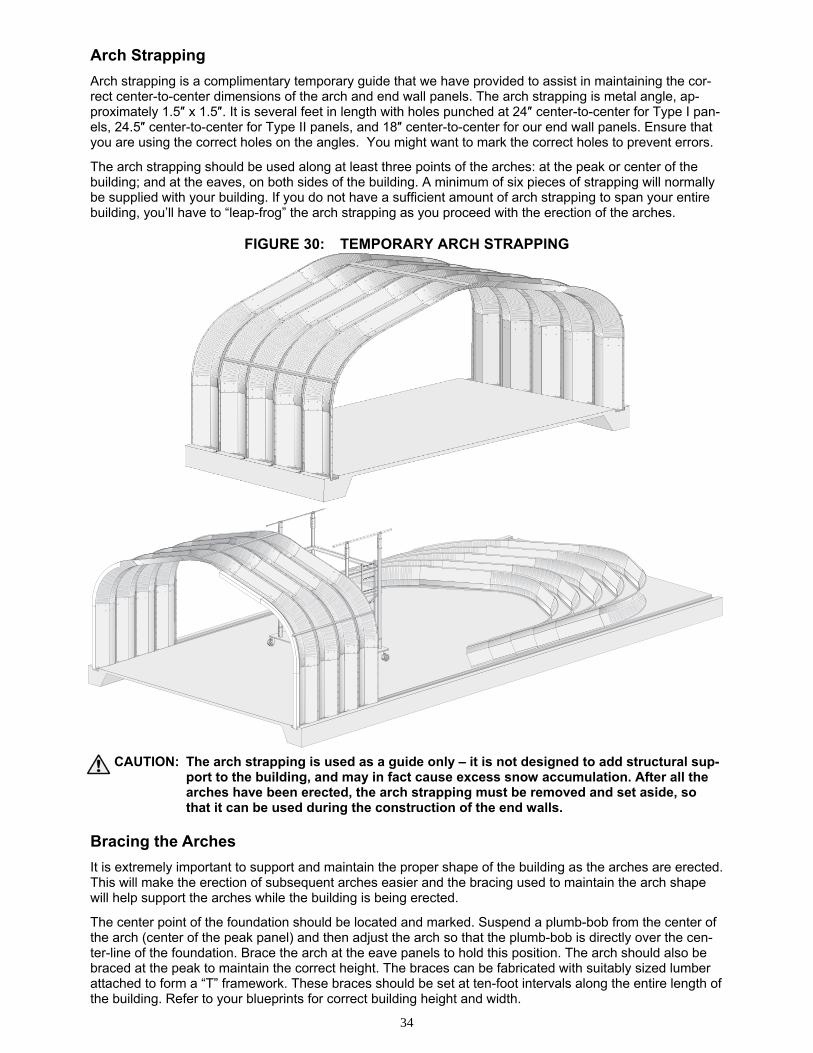
Arch Strapping
Arch strapping is a complimentary temporary guide that we have provided to assist in maintaining the cor-rect center-to-center dimensions of the arch and end wall panels. The arch strapping is metal angle, ap-proximately 1.5″ x 1.5″. It is several feet in length with holes punched at 24″ center-to-center for Type I pan-els, 24.5″ center-to-center for Type II panels, and 18″ center-to-center for our end wall panels. Ensure that you are using the correct holes on the angles. You might want to mark the correct holes to prevent errors.
The arch strapping should be used along at least three points of the arches: at the peak or center of the building; and at the eaves, on both sides of the building. A minimum of six pieces of strapping will normally be supplied with your building. If you do not have a sufficient amount of arch strapping to span your entire building, you’ll have to “leap-frog” the arch strapping as you proceed with the erection of the arches.
FIGURE 30: TEMPORARY ARCH STRAPPING
CAUTION: The arch strapping is used as a guide only – it is not designed to add structural sup-
port to the building, and may in fact cause excess snow accumulation. After all the arches have been erected, the arch strapping must be removed and set aside, so that it can be used during the construction of the end walls.
Bracing the Arches
It is extremely important to support and maintain the proper shape of the building as the arches are erected. This will make the erection of subsequent arches easier and the bracing used to maintain the arch shape will help support the arches while the building is being erected.
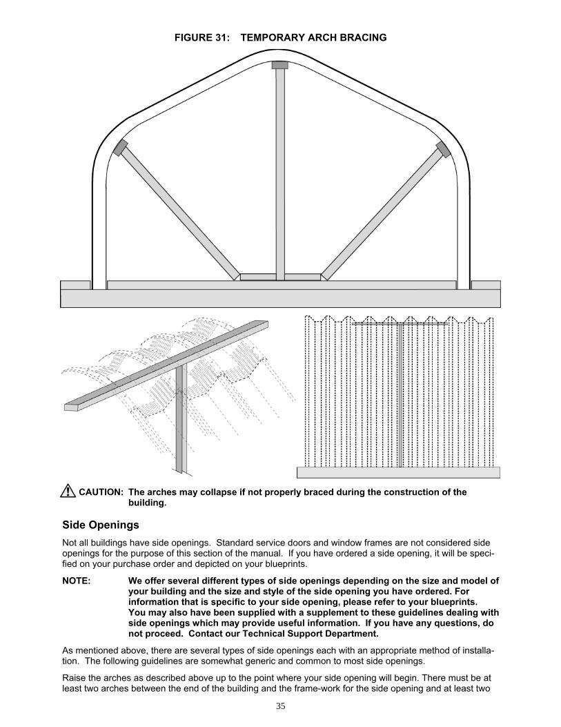
The center point of the foundation should be located and marked. Suspend a plumb-bob from the center of the arch (center of the peak panel) and then adjust the arch so that the plumb-bob is directly over the cen-ter-line of the foundation. Brace the arch at the eave panels to hold this position. The arch should also be braced at the peak to maintain the correct height. The braces can be fabricated with suitably sized lumber attached to form a “T” framework. These braces should be set at ten-foot intervals along the entire length of the building. Refer to your blueprints for correct building height and width.
35
FIGURE 31: TEMPORARY ARCH BRACING
CAUTION: The arches may collapse if not properly braced during the construction of the
building. Side Openings
Not all buildings have side openings. Standard service doors and window frames are not considered side openings for the purpose of this section of the manual. If you have ordered a side opening, it will be speci-fied on your purchase order and depicted on your blueprints.
NOTE: We offer several different types of side openings depending on the size and model of your building and the size and style of the side opening you have ordered. For information that is specific to your side opening, please refer to your blueprints. You may also have been supplied with a supplement to these guidelines dealing with side openings which may provide useful information. If you have any questions, do not proceed. Contact our Technical Support Department.
As mentioned above, there are several types of side openings each with an appropriate method of installa-tion. The following guidelines are somewhat generic and common to most side openings.
Raise the arches as described above up to the point where your side opening will begin. There must be at least two arches between the end of the building and the frame-work for the side opening and at least two
36
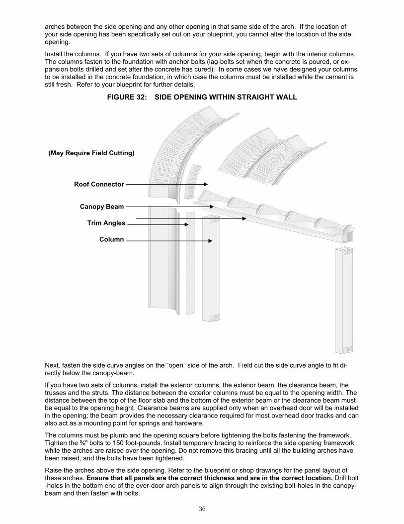
(May Require Field Cutting)
Roof Connector
Canopy Beam
Trim Angles
Column
arches between the side opening and any other opening in that same side of the arch. If the location of your side opening has been specifically set out on your blueprint, you cannot alter the location of the side opening.
Install the columns. If you have two sets of columns for your side opening, begin with the interior columns. The columns fasten to the foundation with anchor bolts (lag-bolts set when the concrete is poured, or ex-pansion bolts drilled and set after the concrete has cured). In some cases we have designed your columns to be installed in the concrete foundation, in which case the columns must be installed while the cement is still fresh. Refer to your blueprint for further details.
FIGURE 32: SIDE OPENING WITHIN STRAIGHT WALL
Next, fasten the side curve angles on the “open” side of the arch. Field cut the side curve angle to fit di-rectly below the canopy-beam.
If you have two sets of columns, install the exterior columns, the exterior beam, the clearance beam, the trusses and the struts. The distance between the exterior columns must be equal to the opening width. The distance between the top of the floor slab and the bottom of the exterior beam or the clearance beam must be equal to the opening height. Clearance beams are supplied only when an overhead door will be installed in the opening; the beam provides the necessary clearance required for most overhead door tracks and can also act as a mounting point for springs and hardware.
The columns must be plumb and the opening square before tightening the bolts fastening the framework. Tighten the ⅝" bolts to 150 foot-pounds. Install temporary bracing to reinforce the side opening framework while the arches are raised over the opening. Do not remove this bracing until all the building arches have been raised, and the bolts have been tightened.
Raise the arches above the side opening. Refer to the blueprint or shop drawings for the panel layout of these arches. Ensure that all panels are the correct thickness and are in the correct location. Drill bolt-holes in the bottom end of the over-door arch panels to align through the existing bolt-holes in the canopy-beam and then fasten with bolts.
37
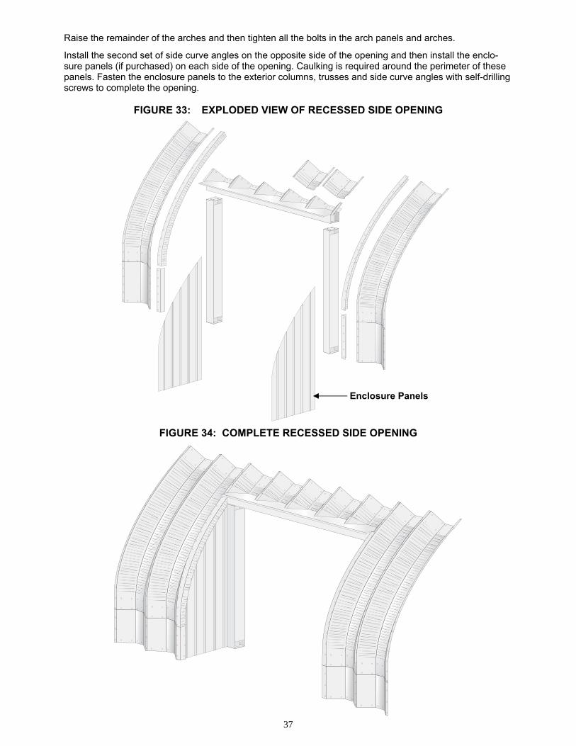
Enclosure Panels
Raise the remainder of the arches and then tighten all the bolts in the arch panels and arches.
Install the second set of side curve angles on the opposite side of the opening and then install the enclo-sure panels (if purchased) on each side of the opening. Caulking is required around the perimeter of these panels. Fasten the enclosure panels to the exterior columns, trusses and side curve angles with self-drilling screws to complete the opening.
FIGURE 33: EXPLODED VIEW OF RECESSED SIDE OPENING
FIGURE 34: COMPLETE RECESSED SIDE OPENING
38
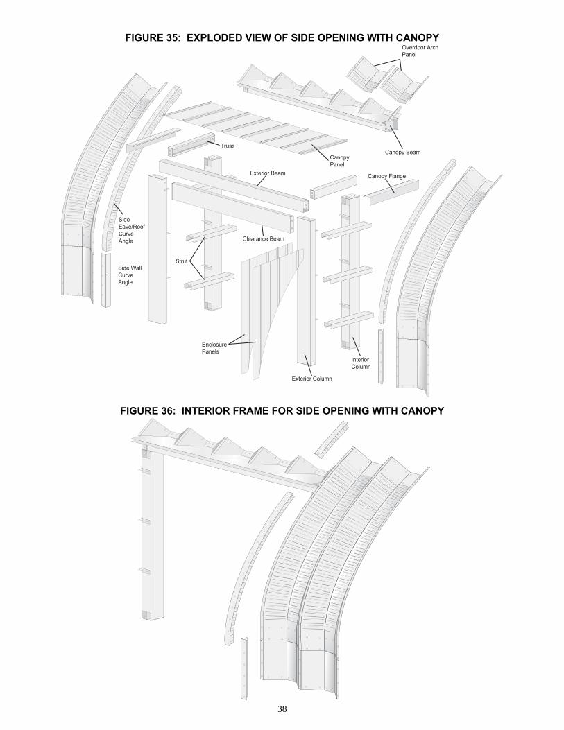
Exterior Beam
Canopy Beam
Clearance Beam
Strut
EnclosurePanels
Exterior Column
Interior Column
Truss
Canopy Flange
Overdoor Arch Panel
Canopy Panel
Side Eave/Roof Curve Angle
Side WallCurve Angle
FIGURE 35: EXPLODED VIEW OF SIDE OPENING WITH CANOPY
FIGURE 36: INTERIOR FRAME FOR SIDE OPENING WITH CANOPY
39
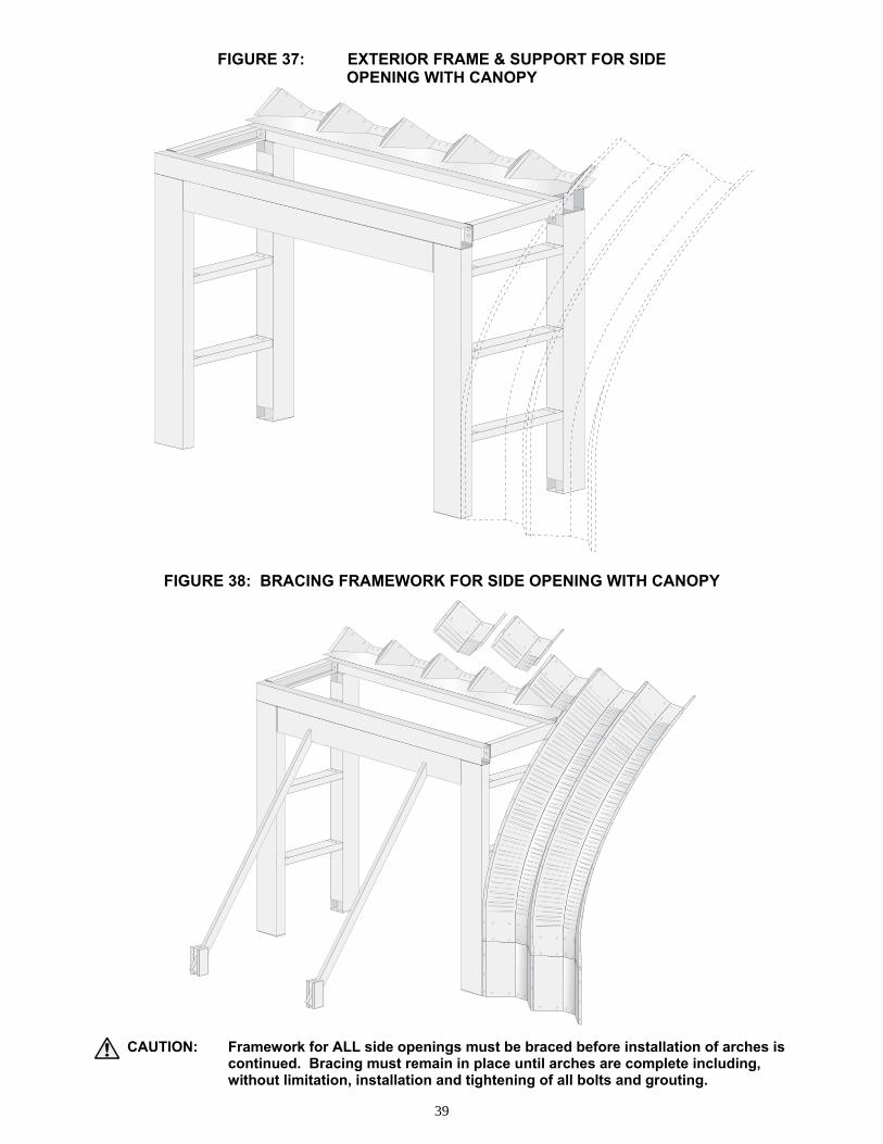
FIGURE 37: EXTERIOR FRAME & SUPPORT FOR SIDE OPENING WITH CANOPY
FIGURE 38: BRACING FRAMEWORK FOR SIDE OPENING WITH CANOPY
CAUTION: Framework for ALL side openings must be braced before installation of arches is continued. Bracing must remain in place until arches are complete including, without limitation, installation and tightening of all bolts and grouting.
40
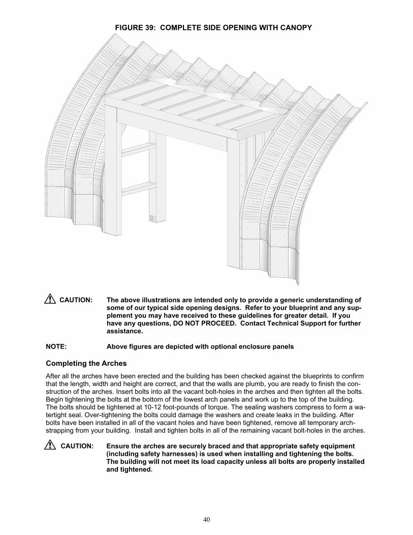
FIGURE 39: COMPLETE SIDE OPENING WITH CANOPY CAUTION: The above illustrations are intended only to provide a generic understanding of
some of our typical side opening designs. Refer to your blueprint and any sup- plement you may have received to these guidelines for greater detail. If you have any questions, DO NOT PROCEED. Contact Technical Support for further assistance. NOTE: Above figures are depicted with optional enclosure panels Completing the Arches
After all the arches have been erected and the building has been checked against the blueprints to confirm that the length, width and height are correct, and that the walls are plumb, you are ready to finish the con-struction of the arches. Insert bolts into all the vacant bolt-holes in the arches and then tighten all the bolts. Begin tightening the bolts at the bottom of the lowest arch panels and work up to the top of the building. The bolts should be tightened at 10-12 foot-pounds of torque. The sealing washers compress to form a wa-tertight seal. Over-tightening the bolts could damage the washers and create leaks in the building. After bolts have been installed in all of the vacant holes and have been tightened, remove all temporary arch-strapping from your building. Install and tighten bolts in all of the remaining vacant bolt-holes in the arches.
CAUTION: Ensure the arches are securely braced and that appropriate safety equipment (including safety harnesses) is used when installing and tightening the bolts. The building will not meet its load capacity unless all bolts are properly installed and tightened.
41
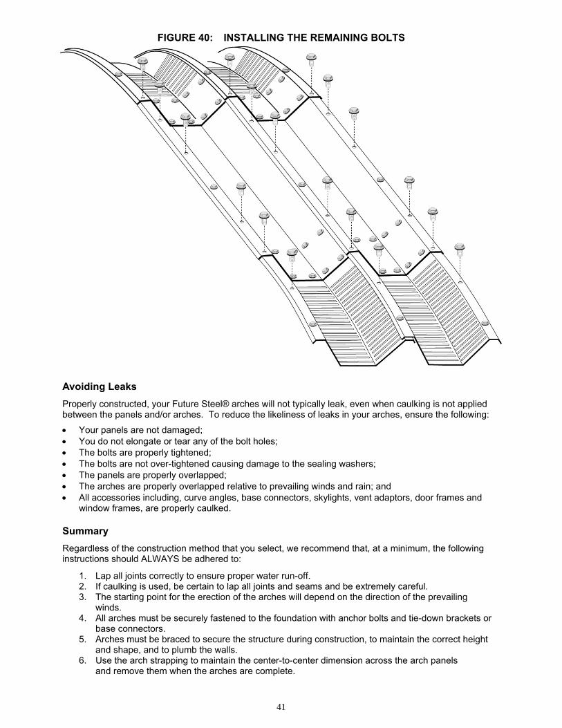
FIGURE 40: INSTALLING THE REMAINING BOLTS Avoiding Leaks
Properly constructed, your Future Steel® arches will not typically leak, even when caulking is not applied between the panels and/or arches. To reduce the likeliness of leaks in your arches, ensure the following:
• Your panels are not damaged; • You do not elongate or tear any of the bolt holes; • The bolts are properly tightened; • The bolts are not over-tightened causing damage to the sealing washers; • The panels are properly overlapped; • The arches are properly overlapped relative to prevailing winds and rain; and • All accessories including, curve angles, base connectors, skylights, vent adaptors, door frames and
window frames, are properly caulked. Summary
Regardless of the construction method that you select, we recommend that, at a minimum, the following instructions should ALWAYS be adhered to:
1. Lap all joints correctly to ensure proper water run-off. 2. If caulking is used, be certain to lap all joints and seams and be extremely careful. 3. The starting point for the erection of the arches will depend on the direction of the prevailing
winds. 4. All arches must be securely fastened to the foundation with anchor bolts and tie-down brackets or
base connectors. 5. Arches must be braced to secure the structure during construction, to maintain the correct height
and shape, and to plumb the walls. 6. Use the arch strapping to maintain the center-to-center dimension across the arch panels
and remove them when the arches are complete.
42
OUTER ANGLE
INNER ANGLE
INNER ANGLE
OUTER ANGLE
Foam
Foam
7. Leave all bolts finger-tight until all the arches have been erected and the building dimensions have been confirmed to be correct. Only install 1 out of every 3 to 4 bolts along the rims where the arches overlap until the arches are all erected to the correct shape and dimensions.
8. After all arches are erect, and the building dimensions are correct, tighten the bolts at 10-12 foot-pounds of torque and remove the arch strapping and internal bracing.
9. Ensure that your curve angles are installed at each end of the building.
By observing the recommended procedures and following the instructions carefully, the arches should be plumb, correctly positioned, secured to the foundation, and set at the correct height, width and shape. This is mandatory for the building to achieve its load capacity and to enable the proper installation of the end walls.
CAUTION: Any errors with the construction of the arches will negatively impact the strength of the building and will likely require some adjustment or modification in order to install the end walls.
It is the responsibility of the person, or persons who are erecting the building to ensure that it is assembled correctly and safely.
If you have any questions or concerns at any stage of construction, DO NOT PROCEED, please contact our Technical Support and Engineering Services Department.
END WALLS
This section applies to FUTURE STEEL® end walls. End walls are installed after all the arches have been erected and all of the bolts in the arches have been tightened. The arches must be correctly positioned and fastened to the foundation and set at the correct profile before end walls are installed. The inner and outer curve angles must also be installed.
The first step in the installation of any style of end wall (whether solid or with an opening) is to mark the centerline of the building on the curve angles and the foundation. Use this reference point to position the end wall panels.
The arch strapping is used during the construction of the end walls to maintain 18″ center-to-center dis-tance between the corrugated end wall panels. If you have purchased arch material end walls, the center-to-center spacing will be 24″ or 24.5″ inches depending on whether Type I or Type II arch panels are being used. As with the arches, do not tighten the bolts on the end wall panels until all the panels have been in-stalled, the end wall is plumb and level and openings, if any, are square. Foam Strips
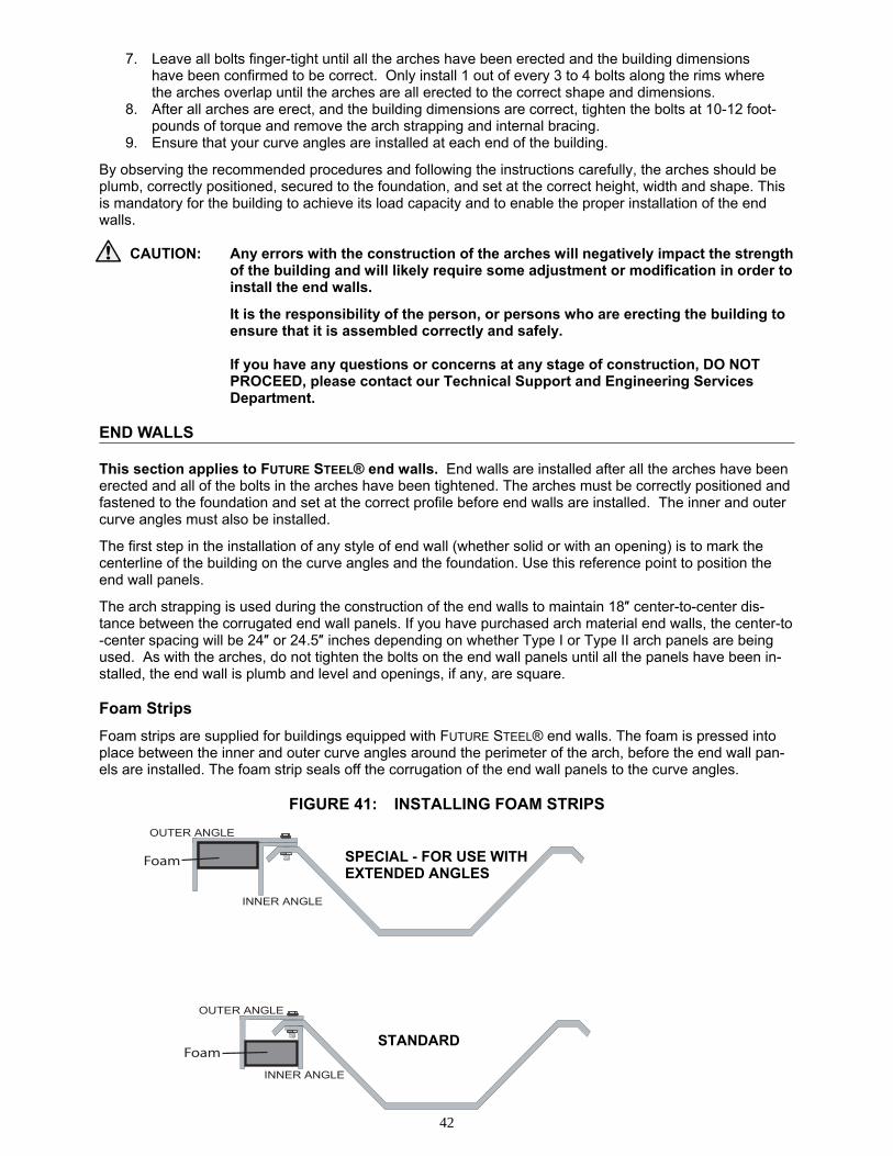
Foam strips are supplied for buildings equipped with FUTURE STEEL® end walls. The foam is pressed into place between the inner and outer curve angles around the perimeter of the arch, before the end wall pan-els are installed. The foam strip seals off the corrugation of the end wall panels to the curve angles.
FIGURE 41: INSTALLING FOAM STRIPS
STANDARD
SPECIAL - FOR USE WITH EXTENDED ANGLES
43
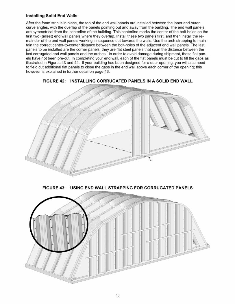
Installing Solid End Walls
After the foam strip is in place, the top of the end wall panels are installed between the inner and outer curve angles, with the overlap of the panels pointing out and away from the building. The end wall panels are symmetrical from the centerline of the building. This centerline marks the center of the bolt-holes on the first two (tallest) end wall panels where they overlap. Install these two panels first, and then install the re-mainder of the end wall panels working in sequence out towards the walls. Use the arch strapping to main-tain the correct center-to-center distance between the bolt-holes of the adjacent end wall panels. The last panels to be installed are the corner panels; they are flat steel panels that span the distance between the last corrugated end wall panels and the arches. In order to avoid damage during shipment, these flat pan-els have not been pre-cut. In completing your end wall, each of the flat panels must be cut to fill the gaps as illustrated in Figures 43 and 44. If your building has been designed for a door opening, you will also need to field cut additional flat panels to close the gaps in the end wall above each corner of the opening; this however is explained in further detail on page 46.
FIGURE 42: INSTALLING CORRUGATED PANELS IN A SOLID END WALL
FIGURE 43: USING END WALL STRAPPING FOR CORRUGATED PANELS
44
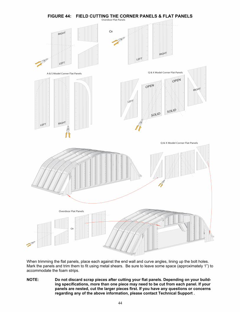
A & S Model Corner Flat Panels
Overdoor Flat Panels
Or
Q & X Model Corner Flat Panels
Q & X Model Corner Flat Panels
Overdoor Flat Panels
Or
FIGURE 44: FIELD CUTTING THE CORNER PANELS & FLAT PANELS
When trimming the flat panels, place each against the end wall and curve angles, lining up the bolt holes. Mark the panels and trim them to fit using metal shears. Be sure to leave some space (approximately 1”) to accommodate the foam strips. NOTE: Do not discard scrap pieces after cutting your flat panels. Depending on your build-
ing specifications, more than one piece may need to be cut from each panel. If your panels are nested, cut the larger pieces first. If you have any questions or concerns regarding any of the above information, please contact Technical Support .
45
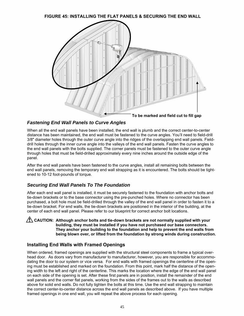
To be marked and field cut to fill gap
FIGURE 45: INSTALLING THE FLAT PANELS & SECURING THE END WALL
Fastening End Wall Panels to Curve Angles
When all the end wall panels have been installed, the end wall is plumb and the correct center-to-center distance has been maintained, the end wall must be fastened to the curve angles. You’ll need to field-drill 3/8″ diameter holes through the outer curve angle into the ridges of the overlapping end wall panels. Field-drill holes through the inner curve angle into the valleys of the end wall panels. Fasten the curve angles to the end wall panels with the bolts supplied. The corner panels must be fastened to the outer curve angle through holes that must be field-drilled approximately every nine inches around the outside edge of the panel.
After the end wall panels have been fastened to the curve angles, install all remaining bolts between the end wall panels, removing the temporary end wall strapping as it is encountered. The bolts should be tight-ened to 10-12 foot-pounds of torque. Securing End Wall Panels To The Foundation
After each end wall panel is installed, it must be securely fastened to the foundation with anchor bolts and tie-down brackets or to the base connector using the pre-punched holes. Where no connector has been purchased, a bolt hole must be field-drilled through the valley of the end wall panel in order to fasten it to a tie-down bracket. For end walls, the tie-down brackets are positioned in the interior of the building, at the center of each end wall panel. Please refer to our blueprint for correct anchor bolt locations.
CAUTION: Although anchor bolts and tie-down brackets are not normally supplied with your building, they must be installed if you have not purchased our base connectors. They anchor your building to the foundation and help to prevent the end walls from being blown over, or lifted from the foundation by strong winds during construction.
Installing End Walls with Framed Openings
When ordered, framed openings are supplied with the structural steel components to frame a typical over-head door. As doors vary from manufacturer to manufacturer, however, you are responsible for accommo-dating the door to our system or vice versa. For end walls with framed openings the centerline of the open-ing must be established and marked on the foundation. From this point, mark half the distance of the open-ing width to the left and right of the centerline. This marks the location where the edge of the end wall panel on each side of the opening is set. After these first panels are in position, install the remainder of the end wall panels and the corner flat panels, working from the sides of the frames out to the walls as described above for solid end walls. Do not fully tighten the bolts at this time. Use the end wall strapping to maintain the correct center-to-center distance across the end wall panels as described above. If you have multiple framed openings in one end wall, you will repeat the above process for each opening.
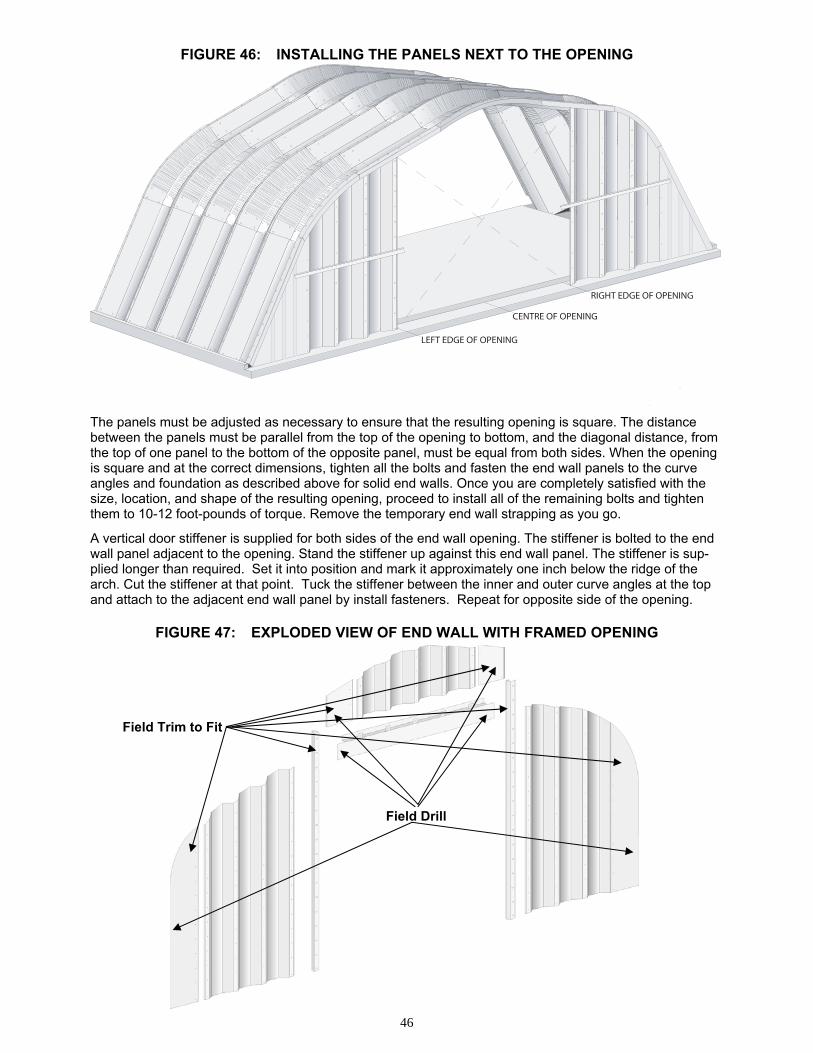
46
Field Trim to Fit
Field Drill
CENTRE OF OPENING
LEFT EDGE OF OPENING
RIGHT EDGE OF OPENING
FIGURE 46: INSTALLING THE PANELS NEXT TO THE OPENING
The panels must be adjusted as necessary to ensure that the resulting opening is square. The distance between the panels must be parallel from the top of the opening to bottom, and the diagonal distance, from the top of one panel to the bottom of the opposite panel, must be equal from both sides. When the opening is square and at the correct dimensions, tighten all the bolts and fasten the end wall panels to the curve angles and foundation as described above for solid end walls. Once you are completely satisfied with the size, location, and shape of the resulting opening, proceed to install all of the remaining bolts and tighten them to 10-12 foot-pounds of torque. Remove the temporary end wall strapping as you go.
A vertical door stiffener is supplied for both sides of the end wall opening. The stiffener is bolted to the end wall panel adjacent to the opening. Stand the stiffener up against this end wall panel. The stiffener is sup-plied longer than required. Set it into position and mark it approximately one inch below the ridge of the arch. Cut the stiffener at that point. Tuck the stiffener between the inner and outer curve angles at the top and attach to the adjacent end wall panel by install fasteners. Repeat for opposite side of the opening.
FIGURE 47: EXPLODED VIEW OF END WALL WITH FRAMED OPENING
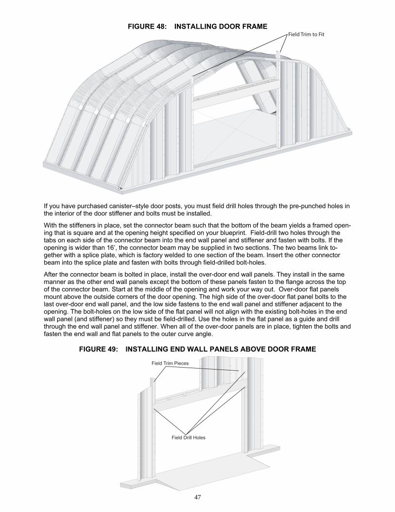
47
Field Trim to Fit
Field Drill Holes
Field Trim Pieces
FIGURE 48: INSTALLING DOOR FRAME
If you have purchased canister–style door posts, you must field drill holes through the pre-punched holes in the interior of the door stiffener and bolts must be installed.
With the stiffeners in place, set the connector beam such that the bottom of the beam yields a framed open-ing that is square and at the opening height specified on your blueprint. Field-drill two holes through the tabs on each side of the connector beam into the end wall panel and stiffener and fasten with bolts. If the opening is wider than 16’, the connector beam may be supplied in two sections. The two beams link to-gether with a splice plate, which is factory welded to one section of the beam. Insert the other connector beam into the splice plate and fasten with bolts through field-drilled bolt-holes.
After the connector beam is bolted in place, install the over-door end wall panels. They install in the same manner as the other end wall panels except the bottom of these panels fasten to the flange across the top of the connector beam. Start at the middle of the opening and work your way out. Over-door flat panels mount above the outside corners of the door opening. The high side of the over-door flat panel bolts to the last over-door end wall panel, and the low side fastens to the end wall panel and stiffener adjacent to the opening. The bolt-holes on the low side of the flat panel will not align with the existing bolt-holes in the end wall panel (and stiffener) so they must be field-drilled. Use the holes in the flat panel as a guide and drill through the end wall panel and stiffener. When all of the over-door panels are in place, tighten the bolts and fasten the end wall and flat panels to the outer curve angle.
FIGURE 49: INSTALLING END WALL PANELS ABOVE DOOR FRAME
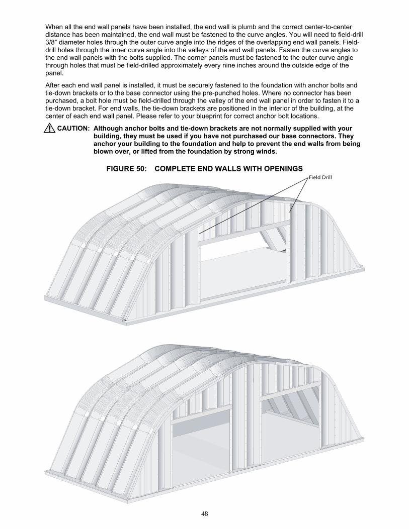
48
Field Drill
When all the end wall panels have been installed, the end wall is plumb and the correct center-to-center distance has been maintained, the end wall must be fastened to the curve angles. You will need to field-drill 3/8″ diameter holes through the outer curve angle into the ridges of the overlapping end wall panels. Field-drill holes through the inner curve angle into the valleys of the end wall panels. Fasten the curve angles to the end wall panels with the bolts supplied. The corner panels must be fastened to the outer curve angle through holes that must be field-drilled approximately every nine inches around the outside edge of the panel.
After each end wall panel is installed, it must be securely fastened to the foundation with anchor bolts and tie-down brackets or to the base connector using the pre-punched holes. Where no connector has been purchased, a bolt hole must be field-drilled through the valley of the end wall panel in order to fasten it to a tie-down bracket. For end walls, the tie-down brackets are positioned in the interior of the building, at the center of each end wall panel. Please refer to your blueprint for correct anchor bolt locations.
CAUTION: Although anchor bolts and tie-down brackets are not normally supplied with your building, they must be used if you have not purchased our base connectors. They anchor your building to the foundation and help to prevent the end walls from being blown over, or lifted from the foundation by strong winds.
FIGURE 50: COMPLETE END WALLS WITH OPENINGS

49
END WALL PANEL
Partition Curve Angles
Industrial EndwallConnector
Anchor Bolt(Not Supplied)
Self-Drilled Screws(Not Supplied)
Partition & Recessed Walls
Walls can be installed within the arches as an interior partition or as a recessed wall to create an arch over-hang, if they have been ordered for such purposes. Installation of partition or recessed end walls is very similar to the installation of standard end walls (whether solid or with an opening). The only difference is that partition/recessed walls fasten to the arches with partition curve angles that normally fasten to the val-ley of the arch panels (as opposed to the end). The horizontal side (the side with the bolt-holes) of these angles is typically wider than the standard inner curve angle, and narrower than standard outer curve an-gles – 2.5" overall. End wall base connector is typically used to anchor partition end walls to the floor. De-pending on the foundation design, partition and recessed end walls can fasten to the foundation with end wall base connector, or to a keyway in the footing in the case of a standard trough-style foundation.
Partition walls are normally centered under the valley of an arch. A pair of partition curve angles overlap through the bolt-holes and fasten to the valley of the arch through a single row of bolt-holes which you must field-drill in the center of the arch valley. For straight wall and straight roof arch panels, use the existing holes in the curve angles as pilot holes. For eave, curved roof and/or peak panels, drill through the existing holes in the curve angles only where these holes align with a flat section (between the indentations) of the panels. This will ensure that the bolts are straight and the washer will seal correctly. Bolt the curve angles to the arch. Where necessary, field-drill additional holes through both the curve angles and the eave and peak arch panels to secure the connection of these pieces.
From three or more points across the span of the arch, suspend a plumb-bob from the curve angle bolts to the floor slab, and mark these points on the slab. Snap a chalk-line on the slab aligned with the marks. Set the end wall base connector in place, aligning the anchor bolt-holes in the connector with the chalk-line. Mark the anchor bolt locations on the slab, set the connector aside, then drill and set expansion bolts (not supplied) into the slab following the bolt manufacturer’s instructions. Fasten the connector into position, and then install the end wall as you would in the case of our standard end wall.
If you are constructing your own partition or recessed end wall, and you have purchased partition angles, a variation of our standard partition curve angle is supplied. You can use one or more of these curve angle sets, in several possible configurations, to attach or seal your wall to the arch. Install non-standard partition angles following the same procedure as described for standard partition angles.
FIGURE 51: CROSS-SECTION OF CORRUGATED PARTITION WALL
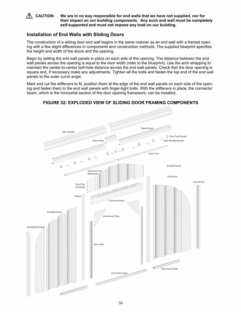
50
Stiffner
End Wall Panels
End Wall Flat Panel
Attachment Plate
Connector Beam
Endwall Panels
Flat Panels
Vertical Post
Rain Shedder
Splicer Plate
Header Beam
Door Track Bracket
Rain Shedder Bracket
Inner Door Guide
Outer Door Guide
Door Jamb
Over Door End Wall Panels
Over Door Flat Panels
Door Track
CAUTION: We are in no way responsible for end walls that we have not supplied, nor for their impact on our building components. Any such end wall must be completely self-supported and must not impose any load on our building. Installation of End Walls with Sliding Doors
The construction of a sliding door end wall begins in the same manner as an end wall with a framed open-ing with a few slight differences in components and construction methods. The supplied blueprint specifies the height and width of the doors and the opening.
Begin by setting the end wall panels in place on each side of the opening. The distance between the end wall panels across the opening is equal to the door width (refer to the blueprint). Use the arch strapping to maintain the center-to-center bolt-hole distance across the end wall panels. Check that the door opening is square and, if necessary make any adjustments. Tighten all the bolts and fasten the top end of the end wall panels to the outer curve angle.
Mark and cut the stiffeners to fit, position them at the edge of the end wall panels on each side of the open-ing and fasten them to the end wall panels with finger-tight bolts. With the stiffeners in place, the connector beam, which is the horizontal section of the door opening framework, can be installed.
FIGURE 52: EXPLODED VIEW OF SLIDING DOOR FRAMING COMPONENTS
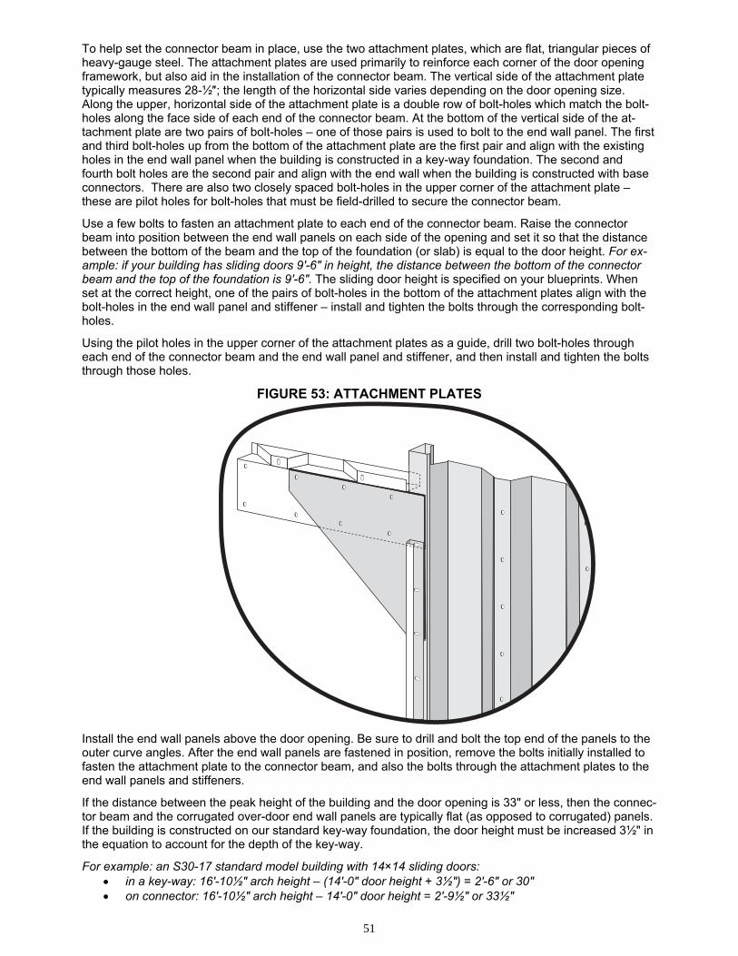
51
To help set the connector beam in place, use the two attachment plates, which are flat, triangular pieces of heavy-gauge steel. The attachment plates are used primarily to reinforce each corner of the door opening framework, but also aid in the installation of the connector beam. The vertical side of the attachment plate typically measures 28-½″; the length of the horizontal side varies depending on the door opening size. Along the upper, horizontal side of the attachment plate is a double row of bolt-holes which match the bolt-holes along the face side of each end of the connector beam. At the bottom of the vertical side of the at-tachment plate are two pairs of bolt-holes – one of those pairs is used to bolt to the end wall panel. The first and third bolt-holes up from the bottom of the attachment plate are the first pair and align with the existing holes in the end wall panel when the building is constructed in a key-way foundation. The second and fourth bolt holes are the second pair and align with the end wall when the building is constructed with base connectors. There are also two closely spaced bolt-holes in the upper corner of the attachment plate – these are pilot holes for bolt-holes that must be field-drilled to secure the connector beam.
Use a few bolts to fasten an attachment plate to each end of the connector beam. Raise the connector beam into position between the end wall panels on each side of the opening and set it so that the distance between the bottom of the beam and the top of the foundation (or slab) is equal to the door height. For ex-ample: if your building has sliding doors 9′-6″ in height, the distance between the bottom of the connector beam and the top of the foundation is 9′-6″. The sliding door height is specified on your blueprints. When set at the correct height, one of the pairs of bolt-holes in the bottom of the attachment plates align with the bolt-holes in the end wall panel and stiffener – install and tighten the bolts through the corresponding bolt-holes.
Using the pilot holes in the upper corner of the attachment plates as a guide, drill two bolt-holes through each end of the connector beam and the end wall panel and stiffener, and then install and tighten the bolts through those holes.
FIGURE 53: ATTACHMENT PLATES
Install the end wall panels above the door opening. Be sure to drill and bolt the top end of the panels to the outer curve angles. After the end wall panels are fastened in position, remove the bolts initially installed to fasten the attachment plate to the connector beam, and also the bolts through the attachment plates to the end wall panels and stiffeners.
If the distance between the peak height of the building and the door opening is 33" or less, then the connec-tor beam and the corrugated over-door end wall panels are typically flat (as opposed to corrugated) panels. If the building is constructed on our standard key-way foundation, the door height must be increased 3½" in the equation to account for the depth of the key-way.
For example: an S30-17 standard model building with 14×14 sliding doors: • in a key-way: 16′-10½″ arch height – (14'-0″ door height + 3½″) = 2′-6″ or 30″ • on connector: 16′-10½″ arch height – 14'-0″ door height = 2′-9½″ or 33½″
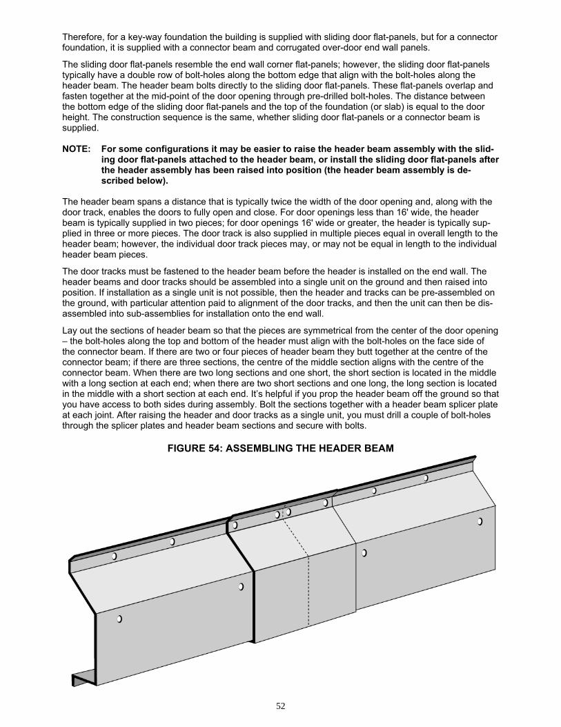
52
Therefore, for a key-way foundation the building is supplied with sliding door flat-panels, but for a connector foundation, it is supplied with a connector beam and corrugated over-door end wall panels.
The sliding door flat-panels resemble the end wall corner flat-panels; however, the sliding door flat-panels typically have a double row of bolt-holes along the bottom edge that align with the bolt-holes along the header beam. The header beam bolts directly to the sliding door flat-panels. These flat-panels overlap and fasten together at the mid-point of the door opening through pre-drilled bolt-holes. The distance between the bottom edge of the sliding door flat-panels and the top of the foundation (or slab) is equal to the door height. The construction sequence is the same, whether sliding door flat-panels or a connector beam is supplied. NOTE: For some configurations it may be easier to raise the header beam assembly with the slid-
ing door flat-panels attached to the header beam, or install the sliding door flat-panels after the header assembly has been raised into position (the header beam assembly is de-scribed below).
The header beam spans a distance that is typically twice the width of the door opening and, along with the door track, enables the doors to fully open and close. For door openings less than 16' wide, the header beam is typically supplied in two pieces; for door openings 16' wide or greater, the header is typically sup-plied in three or more pieces. The door track is also supplied in multiple pieces equal in overall length to the header beam; however, the individual door track pieces may, or may not be equal in length to the individual header beam pieces.
The door tracks must be fastened to the header beam before the header is installed on the end wall. The header beams and door tracks should be assembled into a single unit on the ground and then raised into position. If installation as a single unit is not possible, then the header and tracks can be pre-assembled on the ground, with particular attention paid to alignment of the door tracks, and then the unit can then be dis-assembled into sub-assemblies for installation onto the end wall.
Lay out the sections of header beam so that the pieces are symmetrical from the center of the door opening – the bolt-holes along the top and bottom of the header must align with the bolt-holes on the face side of the connector beam. If there are two or four pieces of header beam they butt together at the centre of the connector beam; if there are three sections, the centre of the middle section aligns with the centre of the connector beam. When there are two long sections and one short, the short section is located in the middle with a long section at each end; when there are two short sections and one long, the long section is located in the middle with a short section at each end. It’s helpful if you prop the header beam off the ground so that you have access to both sides during assembly. Bolt the sections together with a header beam splicer plate at each joint. After raising the header and door tracks as a single unit, you must drill a couple of bolt-holes through the splicer plates and header beam sections and secure with bolts.
FIGURE 54: ASSEMBLING THE HEADER BEAM
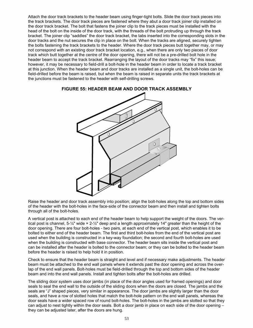
53
Attach the door track brackets to the header beam using finger-tight bolts. Slide the door track pieces into the track brackets. The door track pieces are fastened where they abut a door track joiner clip installed on the door track bracket. The bolt that fastens the joiner clip to the track pieces must be installed with the head of the bolt on the inside of the door track, with the threads of the bolt protruding up through the track bracket. The joiner clip “saddles” the door track bracket, the tabs inserted into the corresponding slots in the door tracks and the nut secures the clip in place on the bolt. When the tracks are aligned, securely tighten the bolts fastening the track brackets to the header. Where the door track pieces butt together may, or may not correspond with an existing door track bracket location, e.g., when there are only two pieces of door track which butt together at the centre of the door opening, there will not be a pre-drilled bolt hole in the header beam to accept the track bracket. Rearranging the layout of the door tracks may “fix” this issue; however, it may be necessary to field-drill a bolt-hole in the header beam in order to locate a track bracket at this junction. When the header beam and door tracks are installed as a single unit, the bolt-holes can be field-drilled before the beam is raised, but when the beam is raised in separate units the track brackets at the junctions must be fastened to the header with self-drilling screws.
FIGURE 55: HEADER BEAM AND DOOR TRACK ASSEMBLY
Raise the header and door track assembly into position; align the bolt-holes along the top and bottom sides of the header with the bolt-holes in the face-side of the connector beam and then install and tighten bolts through all of the bolt-holes.
A vertical post is attached to each end of the header beam to help support the weight of the doors. The ver-tical post is channel, 5-¼" wide × 2-½" deep and a length approximately 14" greater than the height of the door opening. There are four bolt-holes - two pairs, at each end of the vertical post, which enables it to be bolted to either end of the header beam. The first and third bolt-holes from the end of the vertical post are used when the building is constructed in a key-way foundation; the second and fourth bolt-holes are used when the building is constructed with base connector. The header beam sits inside the vertical post and can be installed after the header is bolted to the connector beam; or they can be bolted to the header beam before the header is raised to help hold it in position.
Check to ensure that the header beam is straight and level and if necessary make adjustments. The header beam must be attached to the end wall panels where it extends past the door opening and across the over-lap of the end wall panels. Bolt-holes must be field-drilled through the top and bottom sides of the header beam and into the end wall panels. Install and tighten bolts after the bolt-holes are drilled.
The sliding door system uses door jambs (in place of the door angles used for framed openings) and door seals to seal the end wall to the outside of the sliding doors when the doors are closed. The jambs and the seals are “J” shaped pieces, very similar in appearance. The door jambs are slightly larger than the door seals, and have a row of slotted holes that match the bolt-hole pattern on the end wall panels, whereas the door seals have a wider spaced row of round bolt-holes. The bolt-holes in the jambs are slotted so that they can adjust to nest tightly within the door seals. Bolt a door jamb in place on each side of the door opening – they can be adjusted later, after the doors are hung.
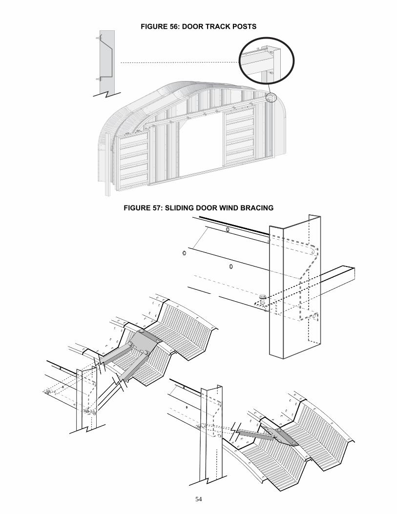
54
FIGURE 56: DOOR TRACK POSTS
FIGURE 57: SLIDING DOOR WIND BRACING
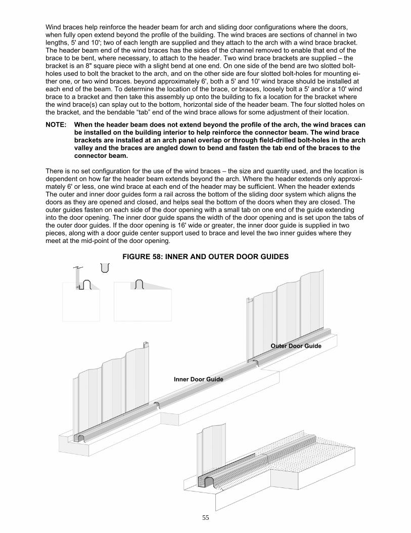
55
Wind braces help reinforce the header beam for arch and sliding door configurations where the doors, when fully open extend beyond the profile of the building. The wind braces are sections of channel in two lengths, 5' and 10'; two of each length are supplied and they attach to the arch with a wind brace bracket. The header beam end of the wind braces has the sides of the channel removed to enable that end of the brace to be bent, where necessary, to attach to the header. Two wind brace brackets are supplied – the bracket is an 8" square piece with a slight bend at one end. On one side of the bend are two slotted bolt-holes used to bolt the bracket to the arch, and on the other side are four slotted bolt-holes for mounting ei-ther one, or two wind braces. beyond approximately 6', both a 5' and 10' wind brace should be installed at each end of the beam. To determine the location of the brace, or braces, loosely bolt a 5' and/or a 10' wind brace to a bracket and then take this assembly up onto the building to fix a location for the bracket where the wind brace(s) can splay out to the bottom, horizontal side of the header beam. The four slotted holes on the bracket, and the bendable “tab” end of the wind brace allows for some adjustment of their location.
NOTE: When the header beam does not extend beyond the profile of the arch, the wind braces can be installed on the building interior to help reinforce the connector beam. The wind brace brackets are installed at an arch panel overlap or through field-drilled bolt-holes in the arch valley and the braces are angled down to bend and fasten the tab end of the braces to the connector beam.
There is no set configuration for the use of the wind braces – the size and quantity used, and the location is dependent on how far the header beam extends beyond the arch. Where the header extends only approxi-mately 6' or less, one wind brace at each end of the header may be sufficient. When the header extends The outer and inner door guides form a rail across the bottom of the sliding door system which aligns the doors as they are opened and closed, and helps seal the bottom of the doors when they are closed. The outer guides fasten on each side of the door opening with a small tab on one end of the guide extending into the door opening. The inner door guide spans the width of the door opening and is set upon the tabs of the outer door guides. If the door opening is 16' wide or greater, the inner door guide is supplied in two pieces, along with a door guide center support used to brace and level the two inner guides where they meet at the mid-point of the door opening.
FIGURE 58: INNER AND OUTER DOOR GUIDES
Inner Door Guide
Outer Door Guide
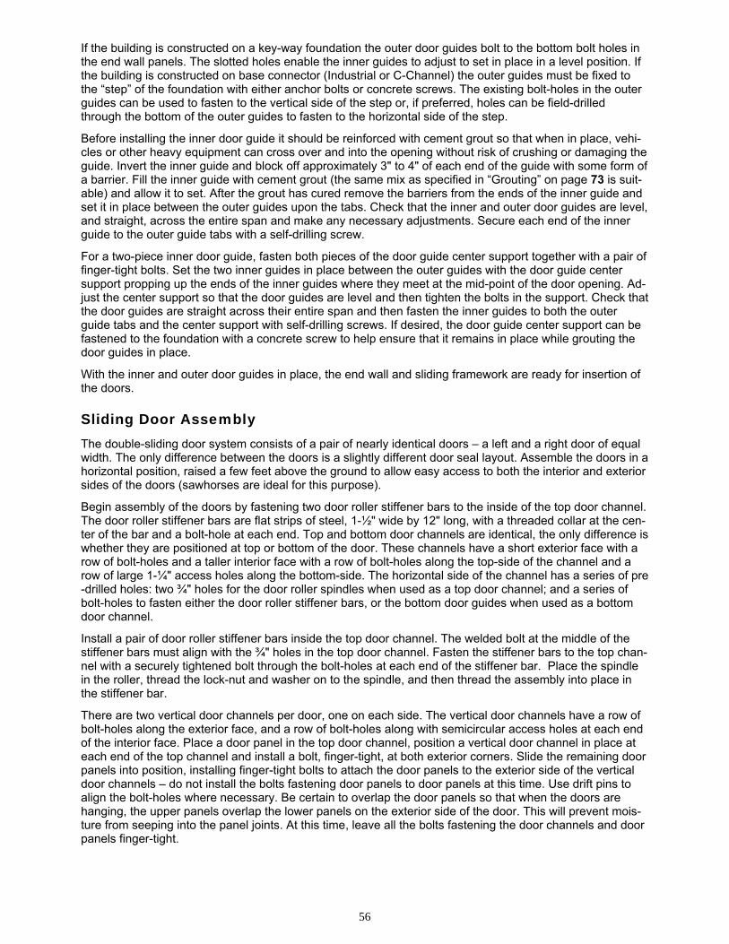
56
If the building is constructed on a key-way foundation the outer door guides bolt to the bottom bolt holes in the end wall panels. The slotted holes enable the inner guides to adjust to set in place in a level position. If the building is constructed on base connector (Industrial or C-Channel) the outer guides must be fixed to the “step” of the foundation with either anchor bolts or concrete screws. The existing bolt-holes in the outer guides can be used to fasten to the vertical side of the step or, if preferred, holes can be field-drilled through the bottom of the outer guides to fasten to the horizontal side of the step.
Before installing the inner door guide it should be reinforced with cement grout so that when in place, vehi-cles or other heavy equipment can cross over and into the opening without risk of crushing or damaging the guide. Invert the inner guide and block off approximately 3" to 4" of each end of the guide with some form of a barrier. Fill the inner guide with cement grout (the same mix as specified in “Grouting” on page 73 is suit-able) and allow it to set. After the grout has cured remove the barriers from the ends of the inner guide and set it in place between the outer guides upon the tabs. Check that the inner and outer door guides are level, and straight, across the entire span and make any necessary adjustments. Secure each end of the inner guide to the outer guide tabs with a self-drilling screw.
For a two-piece inner door guide, fasten both pieces of the door guide center support together with a pair of finger-tight bolts. Set the two inner guides in place between the outer guides with the door guide center support propping up the ends of the inner guides where they meet at the mid-point of the door opening. Ad-just the center support so that the door guides are level and then tighten the bolts in the support. Check that the door guides are straight across their entire span and then fasten the inner guides to both the outer guide tabs and the center support with self-drilling screws. If desired, the door guide center support can be fastened to the foundation with a concrete screw to help ensure that it remains in place while grouting the door guides in place.
With the inner and outer door guides in place, the end wall and sliding framework are ready for insertion of the doors. Sliding Door Assembly
The double-sliding door system consists of a pair of nearly identical doors – a left and a right door of equal width. The only difference between the doors is a slightly different door seal layout. Assemble the doors in a horizontal position, raised a few feet above the ground to allow easy access to both the interior and exterior sides of the doors (sawhorses are ideal for this purpose).
Begin assembly of the doors by fastening two door roller stiffener bars to the inside of the top door channel. The door roller stiffener bars are flat strips of steel, 1-½" wide by 12" long, with a threaded collar at the cen-ter of the bar and a bolt-hole at each end. Top and bottom door channels are identical, the only difference is whether they are positioned at top or bottom of the door. These channels have a short exterior face with a row of bolt-holes and a taller interior face with a row of bolt-holes along the top-side of the channel and a row of large 1-¼" access holes along the bottom-side. The horizontal side of the channel has a series of pre-drilled holes: two ¾" holes for the door roller spindles when used as a top door channel; and a series of bolt-holes to fasten either the door roller stiffener bars, or the bottom door guides when used as a bottom door channel.
Install a pair of door roller stiffener bars inside the top door channel. The welded bolt at the middle of the stiffener bars must align with the ¾" holes in the top door channel. Fasten the stiffener bars to the top chan-nel with a securely tightened bolt through the bolt-holes at each end of the stiffener bar. Place the spindle in the roller, thread the lock-nut and washer on to the spindle, and then thread the assembly into place in the stiffener bar.
There are two vertical door channels per door, one on each side. The vertical door channels have a row of bolt-holes along the exterior face, and a row of bolt-holes along with semicircular access holes at each end of the interior face. Place a door panel in the top door channel, position a vertical door channel in place at each end of the top channel and install a bolt, finger-tight, at both exterior corners. Slide the remaining door panels into position, installing finger-tight bolts to attach the door panels to the exterior side of the vertical door channels – do not install the bolts fastening door panels to door panels at this time. Use drift pins to align the bolt-holes where necessary. Be certain to overlap the door panels so that when the doors are hanging, the upper panels overlap the lower panels on the exterior side of the door. This will prevent mois-ture from seeping into the panel joints. At this time, leave all the bolts fastening the door channels and door panels finger-tight.
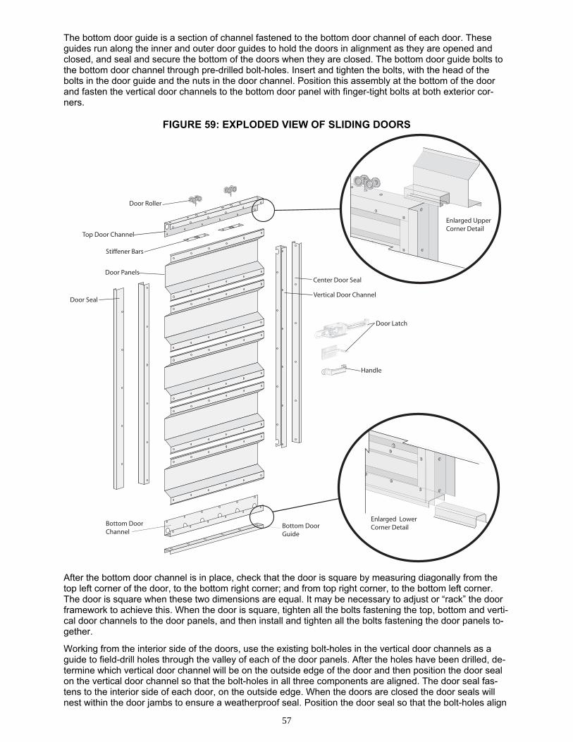
57
The bottom door guide is a section of channel fastened to the bottom door channel of each door. These guides run along the inner and outer door guides to hold the doors in alignment as they are opened and closed, and seal and secure the bottom of the doors when they are closed. The bottom door guide bolts to the bottom door channel through pre-drilled bolt-holes. Insert and tighten the bolts, with the head of the bolts in the door guide and the nuts in the door channel. Position this assembly at the bottom of the door and fasten the vertical door channels to the bottom door panel with finger-tight bolts at both exterior cor-ners.
FIGURE 59: EXPLODED VIEW OF SLIDING DOORS
After the bottom door channel is in place, check that the door is square by measuring diagonally from the top left corner of the door, to the bottom right corner; and from top right corner, to the bottom left corner. The door is square when these two dimensions are equal. It may be necessary to adjust or “rack” the door framework to achieve this. When the door is square, tighten all the bolts fastening the top, bottom and verti-cal door channels to the door panels, and then install and tighten all the bolts fastening the door panels to-gether.
Working from the interior side of the doors, use the existing bolt-holes in the vertical door channels as a guide to field-drill holes through the valley of each of the door panels. After the holes have been drilled, de-termine which vertical door channel will be on the outside edge of the door and then position the door seal on the vertical door channel so that the bolt-holes in all three components are aligned. The door seal fas-tens to the interior side of each door, on the outside edge. When the doors are closed the door seals will nest within the door jambs to ensure a weatherproof seal. Position the door seal so that the bolt-holes align
MMM
E EE
Top Door Channel
Door Roller
Stiffener Bars
Door PanelsCenter Door Seal
Vertical Door ChannelDoor Seal
Bottom Door Channel
Bottom DoorGuide
Door Latch
Handle
Enlarged Lower Corner Detail
Enlarged UpperCorner Detail
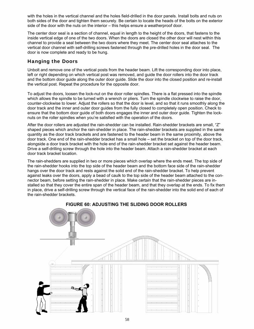
58
with the holes in the vertical channel and the holes field-drilled in the door panels. Install bolts and nuts on both sides of the door and tighten them securely. Be certain to locate the heads of the bolts on the exterior side of the door with the nuts on the interior – this helps ensure a weatherproof door.
The center door seal is a section of channel, equal in length to the height of the doors, that fastens to the inside vertical edge of one of the two doors. When the doors are closed the other door will nest within this channel to provide a seal between the two doors where they meet. The center door seal attaches to the vertical door channel with self-drilling screws fastened through the pre-drilled holes in the door seal. The door is now complete and ready to be hung.
Hanging the Doors
Unbolt and remove one of the vertical posts from the header beam. Lift the corresponding door into place, left or right depending on which vertical post was removed, and guide the door rollers into the door track and the bottom door guide along the outer door guide. Slide the door into the closed position and re-install the vertical post. Repeat the procedure for the opposite door. To adjust the doors, loosen the lock-nut on the door roller spindles. There is a flat pressed into the spindle which allows the spindle to be turned with a wrench or pliers. Turn the spindle clockwise to raise the door, counter-clockwise to lower. Adjust the rollers so that the door is level, and so that it runs smoothly along the door track and the inner and outer door guides from the fully closed to completely open position. Check to ensure that the bottom door guide of both doors engages the inner and outer door guide. Tighten the lock-nuts on the roller spindles when you’re satisfied with the operation of the doors.
After the door rollers are adjusted the rain-shedder can be installed. Rain-shedder brackets are small, “Z” shaped pieces which anchor the rain-shedder in place. The rain-shedder brackets are supplied in the same quantity as the door track brackets and are fastened to the header beam in the same proximity, above the door track. One end of the rain-shedder bracket has a small hole – set the bracket on top of the door track, alongside a door track bracket with the hole end of the rain-shedder bracket set against the header beam. Drive a self-drilling screw through the hole into the header beam. Attach a rain-shedder bracket at each door track bracket location.
The rain-shedders are supplied in two or more pieces which overlap where the ends meet. The top side of the rain-shedder hooks into the top side of the header beam and the bottom face side of the rain-shedder hangs over the door track and rests against the solid end of the rain-shedder bracket. To help prevent against leaks over the doors, apply a bead of caulk to the top side of the header beam attached to the con-nector beam, before setting the rain-shedder in place. Make certain that the rain-shedder pieces are in-stalled so that they cover the entire span of the header beam, and that they overlap at the ends. To fix them in place, drive a self-drilling screw through the vertical face of the rain-shedder into the solid end of each of the rain-shedder brackets.
FIGURE 60: ADJUSTING THE SLIDING DOOR ROLLERS
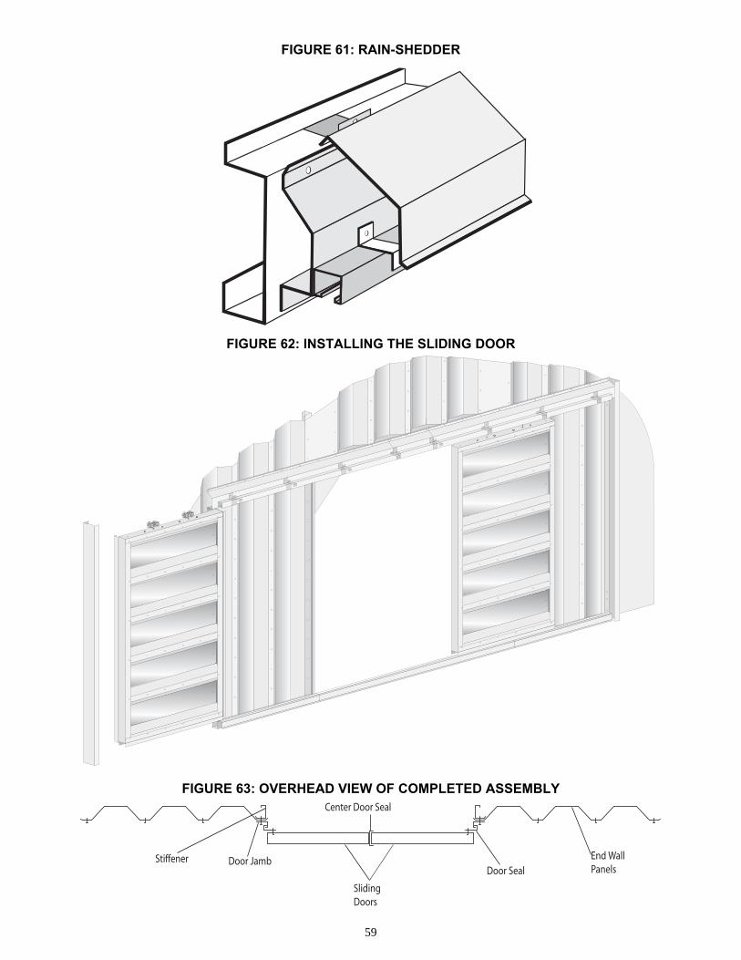
59
FIGURE 61: RAIN-SHEDDER
FIGURE 62: INSTALLING THE SLIDING DOOR
FIGURE 63: OVERHEAD VIEW OF COMPLETED ASSEMBLY
End Wall Panels
Stiffener Door Jamb
SlidingDoors
Center Door Seal
Door Seal
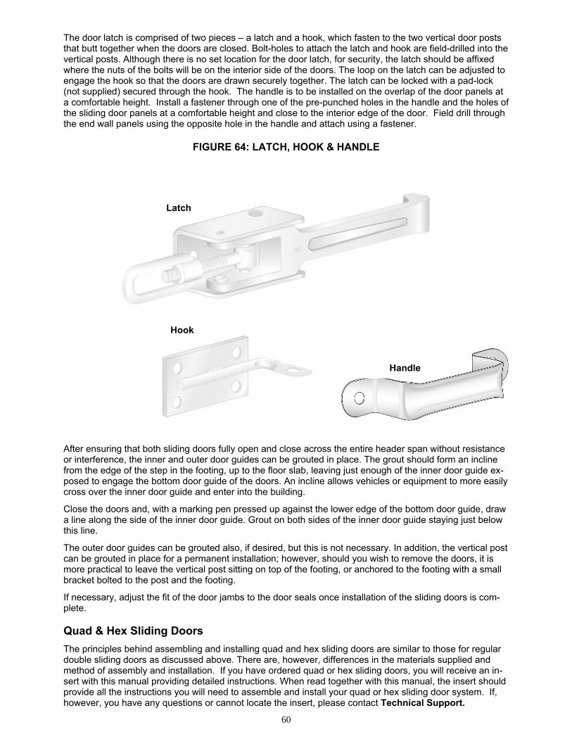
60
The door latch is comprised of two pieces – a latch and a hook, which fasten to the two vertical door posts that butt together when the doors are closed. Bolt-holes to attach the latch and hook are field-drilled into the vertical posts. Although there is no set location for the door latch, for security, the latch should be affixed where the nuts of the bolts will be on the interior side of the doors. The loop on the latch can be adjusted to engage the hook so that the doors are drawn securely together. The latch can be locked with a pad-lock (not supplied) secured through the hook. The handle is to be installed on the overlap of the door panels at a comfortable height. Install a fastener through one of the pre-punched holes in the handle and the holes of the sliding door panels at a comfortable height and close to the interior edge of the door. Field drill through the end wall panels using the opposite hole in the handle and attach using a fastener.
FIGURE 64: LATCH, HOOK & HANDLE
After ensuring that both sliding doors fully open and close across the entire header span without resistance or interference, the inner and outer door guides can be grouted in place. The grout should form an incline from the edge of the step in the footing, up to the floor slab, leaving just enough of the inner door guide ex-posed to engage the bottom door guide of the doors. An incline allows vehicles or equipment to more easily cross over the inner door guide and enter into the building.
Close the doors and, with a marking pen pressed up against the lower edge of the bottom door guide, draw a line along the side of the inner door guide. Grout on both sides of the inner door guide staying just below this line.
The outer door guides can be grouted also, if desired, but this is not necessary. In addition, the vertical post can be grouted in place for a permanent installation; however, should you wish to remove the doors, it is more practical to leave the vertical post sitting on top of the footing, or anchored to the footing with a small bracket bolted to the post and the footing.
If necessary, adjust the fit of the door jambs to the door seals once installation of the sliding doors is com-plete. Quad & Hex Sliding Doors
The principles behind assembling and installing quad and hex sliding doors are similar to those for regular double sliding doors as discussed above. There are, however, differences in the materials supplied and method of assembly and installation. If you have ordered quad or hex sliding doors, you will receive an in-sert with this manual providing detailed instructions. When read together with this manual, the insert should provide all the instructions you will need to assemble and install your quad or hex sliding door system. If, however, you have any questions or cannot locate the insert, please contact Technical Support.
MMMMMM
E EE
Latch
Hook
Handle
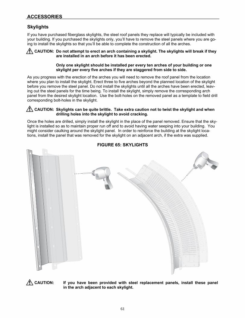
61
ACCESSORIES
Skylights
If you have purchased fiberglass skylights, the steel roof panels they replace will typically be included with your building. If you purchased the skylights only, you’ll have to remove the steel panels where you are go-ing to install the skylights so that you’ll be able to complete the construction of all the arches.
CAUTION: Do not attempt to erect an arch containing a skylight. The skylights will break if they are installed in an arch before it has been erected.
Only one skylight should be installed per every ten arches of your building or one
skylight per every five arches if they are staggered from side to side.
As you progress with the erection of the arches you will need to remove the roof panel from the location where you plan to install the skylight. Erect three to five arches beyond the planned location of the skylight before you remove the steel panel. Do not install the skylights until all the arches have been erected, leav-ing out the steel panels for the time being. To install the skylight, simply remove the corresponding arch panel from the desired skylight location. Use the bolt-holes on the removed panel as a template to field drill corresponding bolt-holes in the skylight.
CAUTION: Skylights can be quite brittle. Take extra caution not to twist the skylight and when
drilling holes into the skylight to avoid cracking.
Once the holes are drilled, simply install the skylight in the place of the panel removed. Ensure that the sky-light is installed so as to maintain proper run off and to avoid having water seeping into your building. You might consider caulking around the skylight panel. In order to reinforce the building at the skylight loca-tions, install the panel that was removed for the skylight on an adjacent arch, if the extra was supplied.
FIGURE 65: SKYLIGHTS
CAUTION: If you have been provided with steel replacement panels, install these panel in the arch adjacent to each skylight.
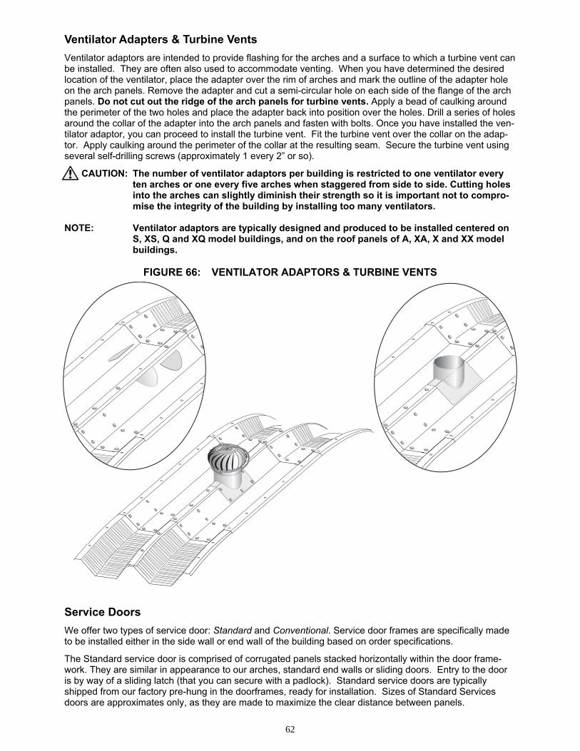
62
Ventilator Adapters & Turbine Vents
Ventilator adaptors are intended to provide flashing for the arches and a surface to which a turbine vent can be installed. They are often also used to accommodate venting. When you have determined the desired location of the ventilator, place the adapter over the rim of arches and mark the outline of the adapter hole on the arch panels. Remove the adapter and cut a semi-circular hole on each side of the flange of the arch panels. Do not cut out the ridge of the arch panels for turbine vents. Apply a bead of caulking around the perimeter of the two holes and place the adapter back into position over the holes. Drill a series of holes around the collar of the adapter into the arch panels and fasten with bolts. Once you have installed the ven-tilator adaptor, you can proceed to install the turbine vent. Fit the turbine vent over the collar on the adap-tor. Apply caulking around the perimeter of the collar at the resulting seam. Secure the turbine vent using several self-drilling screws (approximately 1 every 2” or so).
CAUTION: The number of ventilator adaptors per building is restricted to one ventilator every ten arches or one every five arches when staggered from side to side. Cutting holes into the arches can slightly diminish their strength so it is important not to compro-mise the integrity of the building by installing too many ventilators.
NOTE: Ventilator adaptors are typically designed and produced to be installed centered on S, XS, Q and XQ model buildings, and on the roof panels of A, XA, X and XX model buildings.
FIGURE 66: VENTILATOR ADAPTORS & TURBINE VENTS
Service Doors
We offer two types of service door: Standard and Conventional. Service door frames are specifically made to be installed either in the side wall or end wall of the building based on order specifications.
The Standard service door is comprised of corrugated panels stacked horizontally within the door frame-work. They are similar in appearance to our arches, standard end walls or sliding doors. Entry to the door is by way of a sliding latch (that you can secure with a padlock). Standard service doors are typically shipped from our factory pre-hung in the doorframes, ready for installation. Sizes of Standard Services doors are approximates only, as they are made to maximize the clear distance between panels.
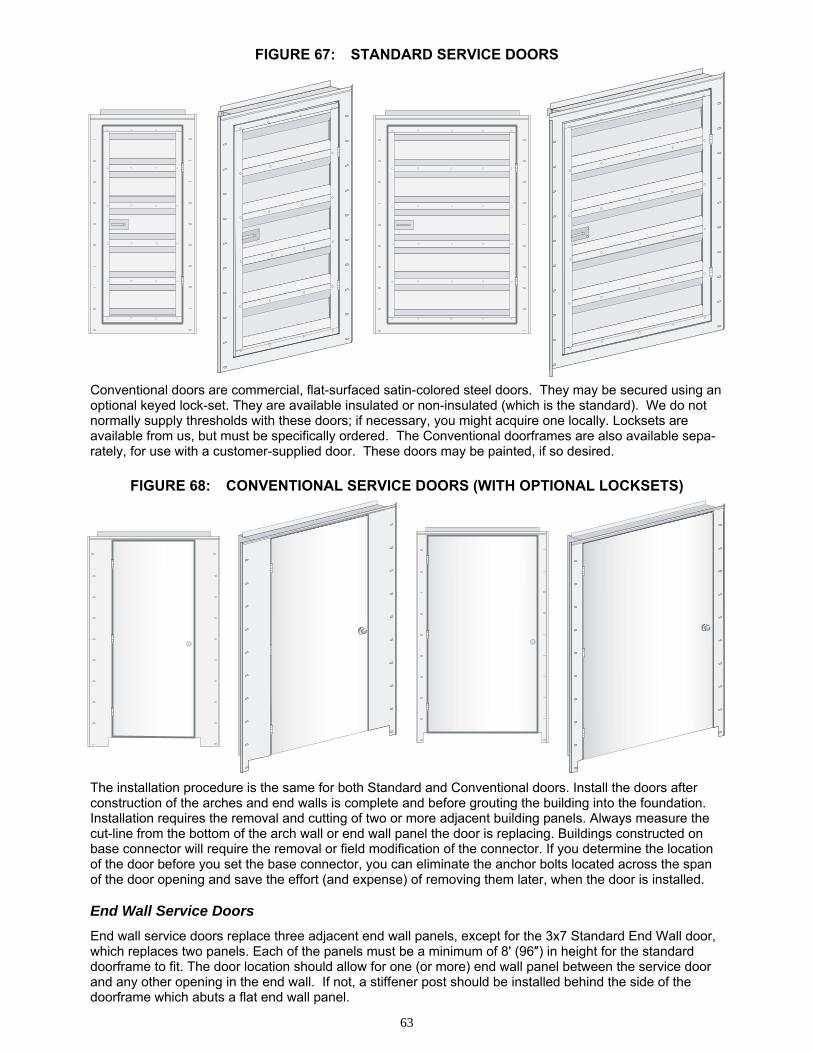
63
FIGURE 67: STANDARD SERVICE DOORS
Conventional doors are commercial, flat-surfaced satin-colored steel doors. They may be secured using an optional keyed lock-set. They are available insulated or non-insulated (which is the standard). We do not normally supply thresholds with these doors; if necessary, you might acquire one locally. Locksets are available from us, but must be specifically ordered. The Conventional doorframes are also available sepa-rately, for use with a customer-supplied door. These doors may be painted, if so desired.
FIGURE 68: CONVENTIONAL SERVICE DOORS (WITH OPTIONAL LOCKSETS)
The installation procedure is the same for both Standard and Conventional doors. Install the doors after construction of the arches and end walls is complete and before grouting the building into the foundation. Installation requires the removal and cutting of two or more adjacent building panels. Always measure the cut-line from the bottom of the arch wall or end wall panel the door is replacing. Buildings constructed on base connector will require the removal or field modification of the connector. If you determine the location of the door before you set the base connector, you can eliminate the anchor bolts located across the span of the door opening and save the effort (and expense) of removing them later, when the door is installed. End Wall Service Doors
End wall service doors replace three adjacent end wall panels, except for the 3x7 Standard End Wall door, which replaces two panels. Each of the panels must be a minimum of 8' (96″) in height for the standard doorframe to fit. The door location should allow for one (or more) end wall panel between the service door and any other opening in the end wall. If not, a stiffener post should be installed behind the side of the doorframe which abuts a flat end wall panel.
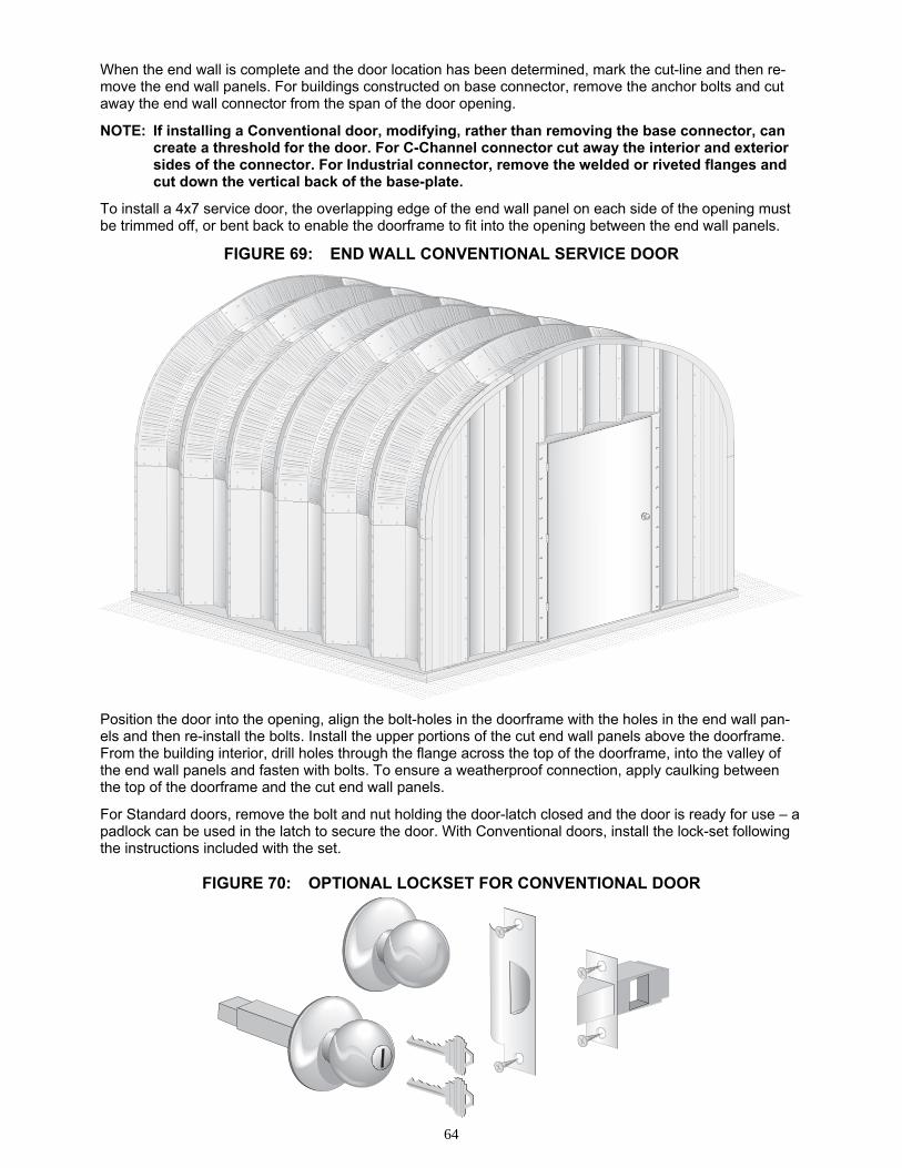
64
When the end wall is complete and the door location has been determined, mark the cut-line and then re-move the end wall panels. For buildings constructed on base connector, remove the anchor bolts and cut away the end wall connector from the span of the door opening.
NOTE: If installing a Conventional door, modifying, rather than removing the base connector, can create a threshold for the door. For C-Channel connector cut away the interior and exterior sides of the connector. For Industrial connector, remove the welded or riveted flanges and cut down the vertical back of the base-plate.
To install a 4x7 service door, the overlapping edge of the end wall panel on each side of the opening must be trimmed off, or bent back to enable the doorframe to fit into the opening between the end wall panels.
FIGURE 69: END WALL CONVENTIONAL SERVICE DOOR
Position the door into the opening, align the bolt-holes in the doorframe with the holes in the end wall pan-els and then re-install the bolts. Install the upper portions of the cut end wall panels above the doorframe. From the building interior, drill holes through the flange across the top of the doorframe, into the valley of the end wall panels and fasten with bolts. To ensure a weatherproof connection, apply caulking between the top of the doorframe and the cut end wall panels.
For Standard doors, remove the bolt and nut holding the door-latch closed and the door is ready for use – a padlock can be used in the latch to secure the door. With Conventional doors, install the lock-set following the instructions included with the set.
FIGURE 70: OPTIONAL LOCKSET FOR CONVENTIONAL DOOR
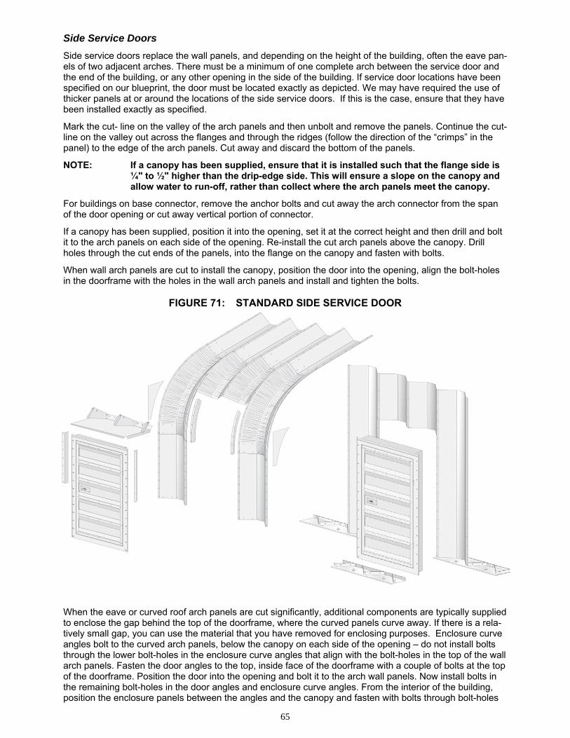
65
Side Service Doors
Side service doors replace the wall panels, and depending on the height of the building, often the eave pan-els of two adjacent arches. There must be a minimum of one complete arch between the service door and the end of the building, or any other opening in the side of the building. If service door locations have been specified on our blueprint, the door must be located exactly as depicted. We may have required the use of thicker panels at or around the locations of the side service doors. If this is the case, ensure that they have been installed exactly as specified.
Mark the cut- line on the valley of the arch panels and then unbolt and remove the panels. Continue the cut-line on the valley out across the flanges and through the ridges (follow the direction of the “crimps” in the panel) to the edge of the arch panels. Cut away and discard the bottom of the panels.
NOTE: If a canopy has been supplied, ensure that it is installed such that the flange side is ¼" to ½" higher than the drip-edge side. This will ensure a slope on the canopy and allow water to run-off, rather than collect where the arch panels meet the canopy.
For buildings on base connector, remove the anchor bolts and cut away the arch connector from the span of the door opening or cut away vertical portion of connector.
If a canopy has been supplied, position it into the opening, set it at the correct height and then drill and bolt it to the arch panels on each side of the opening. Re-install the cut arch panels above the canopy. Drill holes through the cut ends of the panels, into the flange on the canopy and fasten with bolts.
When wall arch panels are cut to install the canopy, position the door into the opening, align the bolt-holes in the doorframe with the holes in the wall arch panels and install and tighten the bolts.
FIGURE 71: STANDARD SIDE SERVICE DOOR
When the eave or curved roof arch panels are cut significantly, additional components are typically supplied to enclose the gap behind the top of the doorframe, where the curved panels curve away. If there is a rela-tively small gap, you can use the material that you have removed for enclosing purposes. Enclosure curve angles bolt to the curved arch panels, below the canopy on each side of the opening – do not install bolts through the lower bolt-holes in the enclosure curve angles that align with the bolt-holes in the top of the wall arch panels. Fasten the door angles to the top, inside face of the doorframe with a couple of bolts at the top of the doorframe. Position the door into the opening and bolt it to the arch wall panels. Now install bolts in the remaining bolt-holes in the door angles and enclosure curve angles. From the interior of the building, position the enclosure panels between the angles and the canopy and fasten with bolts through bolt-holes
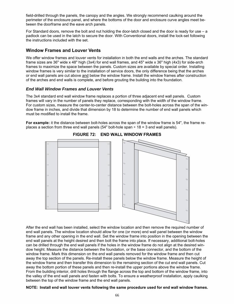
66
field-drilled through the panels, the canopy and the angles. We strongly recommend caulking around the perimeter of the enclosure panel, and where the bottoms of the door and enclosure curve angles meet be-tween the doorframe and the eave arch panels.
For Standard doors, remove the bolt and nut holding the door-latch closed and the door is ready for use – a padlock can be used in the latch to secure the door. With Conventional doors, install the lock-set following the instructions included with the set. Window Frames and Louver Vents
We offer window frames and louver vents for installation in both the end walls and the arches. The standard frame sizes are 36" wide x 48" high (3x4) for end wall frames, and 45" wide x 36" high (4x3) for side-arch frames to maximize the space between the panels. Custom sizes are available by special order. Installing window frames is very similar to the installation of service doors, the only difference being that the arches or end wall panels are cut above and below the window frame. Install the window frames after construction of the arches and end walls is complete, and before grouting the building into the foundation. End Wall Window Frames and Louver Vents
The 3x4 standard end wall window frame replaces a portion of three adjacent end wall panels. Custom frames will vary in the number of panels they replace, corresponding with the width of the window frame. For custom sizes, measure the center-to-center distance between the bolt-holes across the span of the win-dow frame in inches, and divide that dimension by 18 to determine the number of end wall panels which must be modified to install the frame. For example: it the distance between bolt-holes across the span of the window frame is 54", the frame re-places a section from three end wall panels (54" bolt-hole span ÷ 18 = 3 end wall panels).
FIGURE 72: END WALL WINDOW FRAMES After the end wall has been installed, select the window location and then remove the required number of end wall panels. The window location should allow for one (or more) end wall panel between the window frame and any other opening in the end wall. Set the window frame into position in the opening between the end wall panels at the height desired and then bolt the frame into place. If necessary, additional bolt-holes can be drilled through the end wall panels if the holes in the window frame do not align at the desired win-dow height. Measure the distance between the foundation, or the base connector, and the bottom of the window frame. Mark this dimension on the end wall panels removed for the window frame and then cut away the top section of the panels. Re-install these panels below the window frame. Measure the height of the window frame and then transfer this dimension to the remaining section of the cut end wall panels. Cut away the bottom portion of these panels and then re-install the upper portions above the window frame. From the building interior, drill holes through the flange across the top and bottom of the window frame, into the valley of the end wall panels and fasten with bolts. To ensure a weatherproof installation, apply caulking between the top of the window frame and the end wall panels.
NOTE: Install end wall louver vents following the same procedure used for end wall window frames.
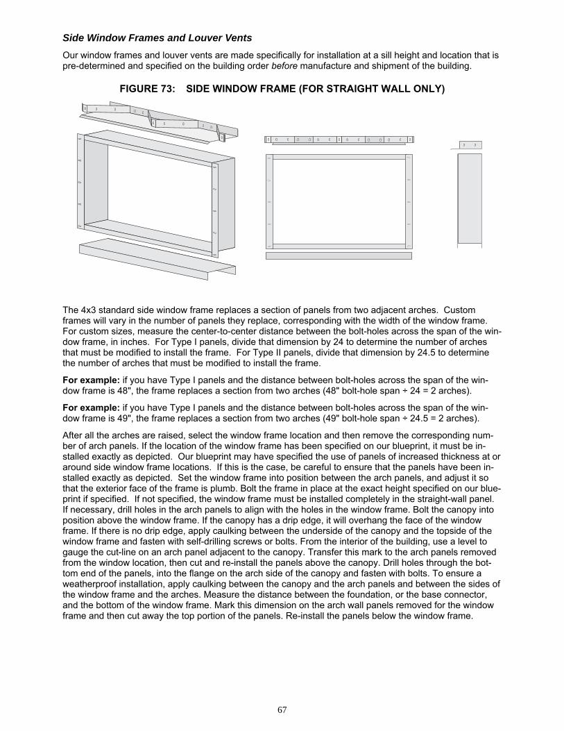
67
Side Window Frames and Louver Vents
Our window frames and louver vents are made specifically for installation at a sill height and location that is pre-determined and specified on the building order before manufacture and shipment of the building.
FIGURE 73: SIDE WINDOW FRAME (FOR STRAIGHT WALL ONLY)
The 4x3 standard side window frame replaces a section of panels from two adjacent arches. Custom frames will vary in the number of panels they replace, corresponding with the width of the window frame. For custom sizes, measure the center-to-center distance between the bolt-holes across the span of the win-dow frame, in inches. For Type I panels, divide that dimension by 24 to determine the number of arches that must be modified to install the frame. For Type II panels, divide that dimension by 24.5 to determine the number of arches that must be modified to install the frame.
For example: if you have Type I panels and the distance between bolt-holes across the span of the win-dow frame is 48", the frame replaces a section from two arches (48" bolt-hole span ÷ 24 = 2 arches).
For example: if you have Type I panels and the distance between bolt-holes across the span of the win-dow frame is 49", the frame replaces a section from two arches (49" bolt-hole span ÷ 24.5 = 2 arches).
After all the arches are raised, select the window frame location and then remove the corresponding num-ber of arch panels. If the location of the window frame has been specified on our blueprint, it must be in-stalled exactly as depicted. Our blueprint may have specified the use of panels of increased thickness at or around side window frame locations. If this is the case, be careful to ensure that the panels have been in-stalled exactly as depicted. Set the window frame into position between the arch panels, and adjust it so that the exterior face of the frame is plumb. Bolt the frame in place at the exact height specified on our blue-print if specified. If not specified, the window frame must be installed completely in the straight-wall panel. If necessary, drill holes in the arch panels to align with the holes in the window frame. Bolt the canopy into position above the window frame. If the canopy has a drip edge, it will overhang the face of the window frame. If there is no drip edge, apply caulking between the underside of the canopy and the topside of the window frame and fasten with self-drilling screws or bolts. From the interior of the building, use a level to gauge the cut-line on an arch panel adjacent to the canopy. Transfer this mark to the arch panels removed from the window location, then cut and re-install the panels above the canopy. Drill holes through the bot-tom end of the panels, into the flange on the arch side of the canopy and fasten with bolts. To ensure a weatherproof installation, apply caulking between the canopy and the arch panels and between the sides of the window frame and the arches. Measure the distance between the foundation, or the base connector, and the bottom of the window frame. Mark this dimension on the arch wall panels removed for the window frame and then cut away the top portion of the panels. Re-install the panels below the window frame.
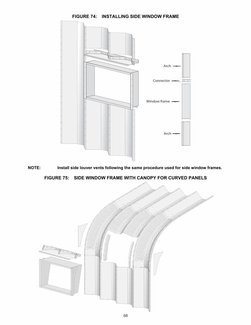
68
FIGURE 74: INSTALLING SIDE WINDOW FRAME NOTE: Install side louver vents following the same procedure used for side window frames.
FIGURE 75: SIDE WINDOW FRAME WITH CANOPY FOR CURVED PANELS
Arch
Arch
Window frame
Connector
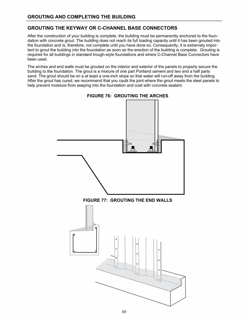
69
GROUTING AND COMPLETING THE BUILDING GROUTING THE KEYWAY OR C-CHANNEL BASE CONNECTORS
After the construction of your building is complete, the building must be permanently anchored to the foun-dation with concrete grout. The building does not reach its full loading capacity until it has been grouted into the foundation and is, therefore, not complete until you have done so. Consequently, it is extremely impor-tant to grout the building into the foundation as soon as the erection of the building is complete. Grouting is required for all buildings in standard trough-style foundations and where C-Channel Base Connectors have been used.
The arches and end walls must be grouted on the interior and exterior of the panels to properly secure the building to the foundation. The grout is a mixture of one part Portland cement and two and a half parts sand. The grout should be on a at least a one-inch slope so that water will run-off away from the building. After the grout has cured, we recommend that you caulk the joint where the grout meets the steel panels to help prevent moisture from seeping into the foundation and coat with concrete sealant.
FIGURE 76: GROUTING THE ARCHES
FIGURE 77: GROUTING THE END WALLS
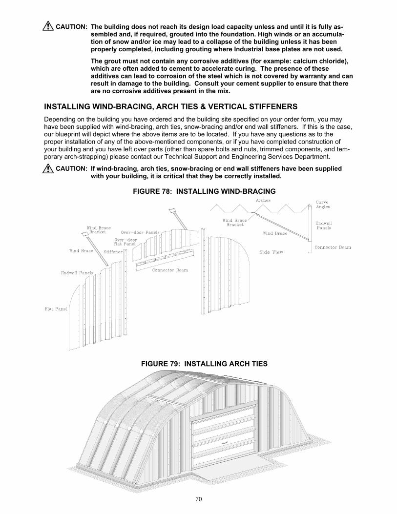
70
CAUTION: The building does not reach its design load capacity unless and until it is fully as-sembled and, if required, grouted into the foundation. High winds or an accumula-tion of snow and/or ice may lead to a collapse of the building unless it has been properly completed, including grouting where Industrial base plates are not used.
The grout must not contain any corrosive additives (for example: calcium chloride), which are often added to cement to accelerate curing. The presence of these additives can lead to corrosion of the steel which is not covered by warranty and can result in damage to the building. Consult your cement supplier to ensure that there are no corrosive additives present in the mix. INSTALLING WIND-BRACING, ARCH TIES & VERTICAL STIFFENERS
Depending on the building you have ordered and the building site specified on your order form, you may have been supplied with wind-bracing, arch ties, snow-bracing and/or end wall stiffeners. If this is the case, our blueprint will depict where the above items are to be located. If you have any questions as to the proper installation of any of the above-mentioned components, or if you have completed construction of your building and you have left over parts (other than spare bolts and nuts, trimmed components, and tem-porary arch-strapping) please contact our Technical Support and Engineering Services Department.
CAUTION: If wind-bracing, arch ties, snow-bracing or end wall stiffeners have been supplied with your building, it is critical that they be correctly installed.
FIGURE 78: INSTALLING WIND-BRACING
FIGURE 79: INSTALLING ARCH TIES
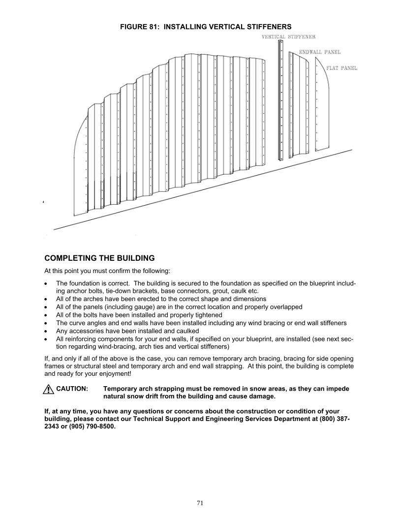
71
FIGURE 81: INSTALLING VERTICAL STIFFENERS
COMPLETING THE BUILDING
At this point you must confirm the following:
• The foundation is correct. The building is secured to the foundation as specified on the blueprint includ-ing anchor bolts, tie-down brackets, base connectors, grout, caulk etc.
• All of the arches have been erected to the correct shape and dimensions • All of the panels (including gauge) are in the correct location and properly overlapped • All of the bolts have been installed and properly tightened • The curve angles and end walls have been installed including any wind bracing or end wall stiffeners • Any accessories have been installed and caulked • All reinforcing components for your end walls, if specified on your blueprint, are installed (see next sec-
tion regarding wind-bracing, arch ties and vertical stiffeners)
If, and only if all of the above is the case, you can remove temporary arch bracing, bracing for side opening frames or structural steel and temporary arch and end wall strapping. At this point, the building is complete and ready for your enjoyment!
CAUTION: Temporary arch strapping must be removed in snow areas, as they can impede natural snow drift from the building and cause damage.
If, at any time, you have any questions or concerns about the construction or condition of your building, please contact our Technical Support and Engineering Services Department at (800) 387-2343 or (905) 790-8500.
72
BUILDING MAINTENANCE AND PREVENTING DAMAGE
Properly constructed and well-maintained, your FUTURE STEEL® building can provide you with a lifetime of enjoyment. This section of the manual contains important tips that, when followed, will help to ensure that you receive the full benefit of your FUTURE STEEL® building. Preventing Damage to your Building
Snow Removal
As stated above, your building has a specific snow load capacity. The building will not, however, achieve its full loading capacity unless the building and the foundation are properly constructed including grouting and the use of tie-down brackets and anchor bolts. Remember that the building was designed based on the conditions on our purchase order, including the type of foundation (when not otherwise specified, the foundation on the blueprint), building occupancy or usage, wind exposure condition, snow shadow condi-tion, building site address, soil and concrete specifications specified on the blueprint, proper construction, the lack absence of collateral loads and based on the design loads in force at the time of purchase. If for any reason, any of the above is not in accordance with our design criteria or if actual snow and ice accumu-lation exceed the capacities specified on our blueprint, damage could result. If you notice that snow is ac-cumulating on your FUTURE STEEL® building, please ensure that it is removed. At the very minimum, you should remove as much snow as possible from the structure using a broom or shovel without climbing on the building. This will assist in preventing “acts of God” which are not covered under your warranty and may not be covered by your insurer.
CAUTION: Remove accumulated snow and ice from your building. Take all appropriate precautions when clearing the snow to avoid injury.
Burying your Building and/or Unaccounted for Collateral Loads
Do not bury your building. FUTURE STEEL® is in no way responsible for damage that may result to a buried building unless we have specifically designed your building for this purpose as clearly indicated on your order form.
Unless specified otherwise on your contract and blueprints, we have not designed for any collateral loads to be imposed on the building save and except for minimal loads like fiberglass insulation, minor lighting fix-tures and electrical plugs and switches. The weight imposed by minor lighting fixtures or the like must be evenly spread across several arches. You may be able to use your temporary arch strapping for this pur-pose. Any other collateral load must be completely independently supported.
CAUTION: Do not bury your building or add any collateral loads which were not accounted for in our design.
Preventing Corrosion & Discoloration to your Building
Galvalume Plus® components are covered by a limited warranty direct from the steel mill against perfora-tions caused by oxidation. For more information regarding this warranty (the warranty we supply to the dis-tributorship from which you purchased your building components) please refer to the following section of this manual. There are exclusions to this warranty that you should be cognizant of. Cleaning your Building
When construction is complete, you may notice some dark residue on some of your panels. Most of the time, this is just residue from your building’s protective Galvalume Plus® coating or dirt. Residue of this nature, as well as dust and dirt can be removed using simple dish detergent and lukewarm water.
CAUTION: Use all appropriate safety equipment when cleaning your building to avoid injury.
The building can be especially slippery when it has just been cleaned. Avoid Contact With Corrosive Material
There are some corrosive materials that may cause discoloration to your building. Discoloration that results from the application or use of these corrosive materials is not covered by our warranty. In particular, there are often corrosive chemicals added to grout to allow the cement to cure faster that can cause discoloration or oxidation to your building components. Please refer to the sections of this manual relating to Grouting for further details. If your building has discoloration of this nature, you can paint the affected areas using alumi-
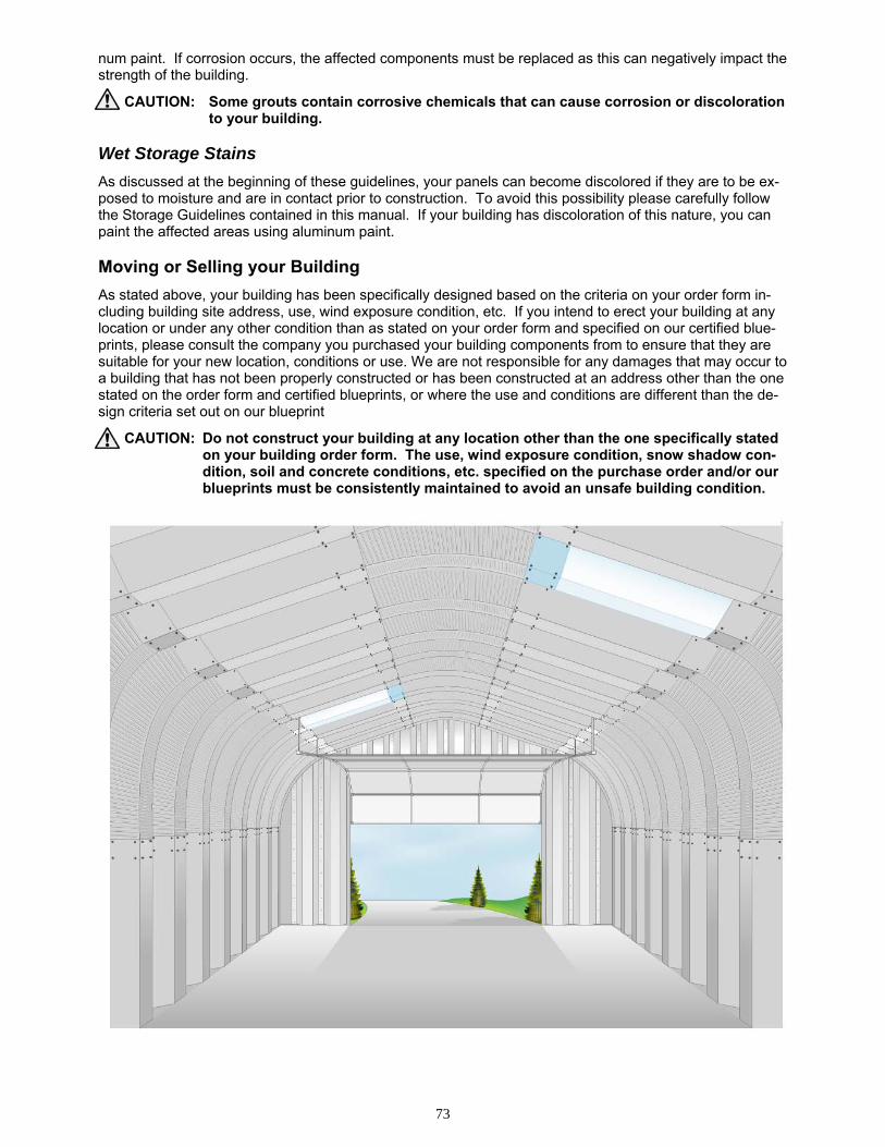
73
num paint. If corrosion occurs, the affected components must be replaced as this can negatively impact the strength of the building.
CAUTION: Some grouts contain corrosive chemicals that can cause corrosion or discoloration to your building.
Wet Storage Stains
As discussed at the beginning of these guidelines, your panels can become discolored if they are to be ex-posed to moisture and are in contact prior to construction. To avoid this possibility please carefully follow the Storage Guidelines contained in this manual. If your building has discoloration of this nature, you can paint the affected areas using aluminum paint. Moving or Selling your Building
As stated above, your building has been specifically designed based on the criteria on your order form in-cluding building site address, use, wind exposure condition, etc. If you intend to erect your building at any location or under any other condition than as stated on your order form and specified on our certified blue-prints, please consult the company you purchased your building components from to ensure that they are suitable for your new location, conditions or use. We are not responsible for any damages that may occur to a building that has not been properly constructed or has been constructed at an address other than the one stated on the order form and certified blueprints, or where the use and conditions are different than the de-sign criteria set out on our blueprint
CAUTION: Do not construct your building at any location other than the one specifically stated on your building order form. The use, wind exposure condition, snow shadow con-dition, soil and concrete conditions, etc. specified on the purchase order and/or our blueprints must be consistently maintained to avoid an unsafe building condition.
74
FUTURE STEEL BUILDINGS INTL. CORP. WARRANTY CERTIFICATE
30 DAY WARRANTY AGAINST SHORTAGES AND DEFECTS We will replace any item that was purchased from us, but which was not loaded for delivery or which was defective in material or workmanship. In order to qualify for this warranty, said shortage or defect must be documented in writing on our Bill of Lading and/or reported to us within thirty (30) days of delivery. In the event of nonconformance with the above warranty, we shall produce the replacement components within a reasonable period of time and deliver them to the original delivery location using a method of delivery of our own selection at no charge to our customer. If, however, in the case of a shortage, the carrier has acknowledged receipt of the product that is alleged to be missing, we shall only be responsible for filing a claim with said carrier and for any re-sulting recovery. This warranty is subject to the limitations and exclusions set out below.
30 YEAR LIMITED WARRANTY ON PERFORATIONS CAUSED BY OXIDATION Components produced from AZM180 Galvalume Plus® steel will not perforate as a consequence of oxidation within a period of thirty (30) years from the date of shipment from our facilities due to exposure to normal atmospheric corrosion. This warranty shall not extend to components that have been damaged, welded or exposed to corrosive, aggressive, harmful or other abnormal atmos-pheric conditions including, but not limited to: areas subject to salt water atmospheres, fallout or exposure to corrosive chemicals, fumes, ash, cement dust or animal waste; areas subject to water run-off from lead or copper flashings or areas in contact with lead or copper; areas in contact or close proximity to damp insulation or other corrosive materials or subject to spraying of either salt or fresh water; areas where corrosive fumes of condensates are generated or released inside the building; areas that come into contact with green or wet lumber; areas where the free drainage of water was prevented and water or debris was allowed to accumulate on the component; and/or areas where damage was caused to the metallic coating. This warranty is subject to the limitations and ex-clusions set out below.
30 YEAR LIMITED WARRANTY ON DAMAGE CAUSED BY SNOW OR WIND In the event of snow or wind damage to a properly and completely constructed building system within a period of thirty (30) years from the date of delivery, we shall produce replacements for the damaged components using materials of equal or superior quality to the originals and deliver them to the original shipping location at no charge. This warranty is subject to the limitations and exclu-sions set out below.
LIMITATIONS AND EXCLUSIONS In no event shall any of our warranties extend beyond the supply of replacement components for the missing, defective or damaged components. Without limiting the foregoing, under no circumstance will we be liable for any cost of labor or consequential dam-ages related in any way to any shortage, defect or damage. We reserve the right to select the method of repair or replacement and delivery at our sole discretion and to settle warranty claims directly with the end-use customer. Any dispute about quality, quantity, condition or workmanship shall not entitle the customer to reject our components or to refuse payment for the same. In the event of any such dispute, the customer must accept delivery of the components and make a short-shipment or warranty claim. In order to qualify for the above warranties, the short-shipment, defect or damage claim must be communicated to us immediately upon dis-covery and we must be provided with adequate opportunity and appropriate information to properly investigate the claim including, without limitation, the customer’s provision of such measurements, documents, information, photographs, etc. as we may reasona-bly request. We provide no warranty whatsoever for any shortage, defect or damage that results directly or indirectly from any oc-currence that is beyond our control including, without limitation, any negligence, shipping error, misuse, abuse, neglect, willful damage, faulty construction or force majeure. Our warranty against snow and wind damage is not applicable in any of the follow-ing circumstances: where the actual loads imposed on the product exceeded the product’s design load capacity as specified on our most current blueprint; where the building site location does not match the building site location specified on our most current blue-print; where the building has not been constructed in accordance with our most current design and instructions; where the site con-ditions including, without limitation, the wind and/or snow exposure conditions (including snow shadow) do not match the condi-tions specified on our blueprint (without limitation, no snow shadow is accounted for unless specifically stated on purchase order); where the soil and site conditions deviate from our most current blueprint; where the foundation, arch anchorage, structural sup-ports, masonry walls, or any other structural element deviates from our most current blueprint; in cases where our most current blueprint does not indicate that the foundation, structural supports, masonry walls, or any other structural element would be de-signed and/or supplied by others and such structural elements are inadequate; where our product has been modified or previously damaged; where additional loads are imposed on the product without our prior approval (no additional loads have been approved unless they are specified on our most current blueprint); where the use of the building is not proper or consistent with the use indi-cated on our most current blueprint (without limitation, low importance or minor storage is assumed unless otherwise stated on the purchase order); where the product is attached to another structure, or where another structure has been attached to our building and this is not reflected on our blueprint, or the information provided to us regarding the attached structure is inaccurate (including, without limitation, the dimensions of the structure that our product is to be attached to and the location and orientation of our build-ing in relation to said structure); where the damage is not directly caused by the wind or snow but by some intervening act includ-ing, without limitation, impact from other objects; where the customer has failed, refused or neglected to confirm the adequacy of our design with local building authorities prior to erection; and/or where the customer has failed, refused or neglected to maintain the product including, without limitation, the removal of snow or other loads in excess of the product’s capacity as specified on our certified drawings. The above warranties are the only warranties that we provide and are in lieu of any other representation or war-ranty, express or implied, and without limiting the generality of the foregoing, we specifically disclaim any representation or war-ranty that our components are fit and/or suitable for the customer’s intended use and/or purpose.