Building Product Catalogue 2015 - Schneider Electric · PDF fileBuilding Product Catalogue...
255
Building Product Catalogue 2015 We are the architects of efficiency, your global partner that can solve the efficiency equation. 15434_Building cvr 6_single.indd 1 10/18/13 11:20 AM
Transcript of Building Product Catalogue 2015 - Schneider Electric · PDF fileBuilding Product Catalogue...

Building ProductCatalogue2015
We are the architects of efficiency, your global partnerthat can solve the efficiency equation.
15434_Building cvr 6_single.indd 1 10/18/13 11:20 AM

15434_Building cvr 6_single.indd 215434_Building cvr 6_single.indd 2 10/18/13 11:20 AM10/18/13 11:20 AM

Contents
Zone Valves & Actuators AG/AH Actuator A-1 AG13U000 ACT 2POS 230V NC GCOAG13U020 ACT 2POS 230V NC GCO 18IN WIREAH13U000 ACT 2POS 230V NC HCOAH13U020 ACT 2POS 230V NC HCO 18IN WIRE
VT Series Valves A-5VT2223 VLV 2POS 2W 15MM KV3.0 NPTVT2233 VLV 2POS 2W 15MM KV3.0 RPVT2325 VLV 2POS 2W 20MM KV4.3 NPTVT2335 VLV 2POS 2W 20MM KV4.3 RPVT2427 VLV 2POS 2W 25MM KV7.0 NPTVT2437 VLV 2POS 2W 25MM KV7.0 RPVT3233 VLV 2POS 3W 15MM KV3.5 RPVT3223 VLV 2POS 3W 15MM KV4.0 NPTVT3325 VLV 2POS 3W 20MM KV4.3 NPTVT3335 VLV 2POS 3W 20MM KV4.3 RPVT3437 VLV 2POS 2W 25MM KV7.0 RPVT3427 VLV 2POS 3W 25MM KV8.0 NPTVT2223H13U020 VLV 2POS 3W 15MM NPT 230V HCO 18INVT2223H13U000 VLV 2POS 2W 15MM NPT 230V HCO 6INVT2223G13U020 VLV 2POS 2W 15MM NPT 230V GCO 18INVT2223G13U000 VLV 2POS 2W 15MM NPT 230V GCO 6INVT2233H13U020 VLV 2POS 2W 15MM RP 230V HCO 18INVT2233H13U000 VLV 2POS 2W 15MM RP 230V HCO 6INVT2233G13U020 VLV 2POS 2W 15MM RP 230V GCO 18INVT2233G13U000 VLV 2POS 2W 15MM RP 230V GCO 6INVT2325G13U020 VLV 2POS 2W 20MM NPT 230V GCO 18INVT2325H13U000 VLV 2POS 2W 20MM NPT 230V HCO 18INVT2325H13U020 VLV 2POS 2W 20MM NPT 230V HCO 18INVT2335H13U020 VLV 2POS 2W 20MM RP 230V HCO 18INVT2335H13U000 VLV 2POS 2W 20MM RP 230V HCO 6INVT2427H13U000 VLV 2POS 2W 25MM NPT 230V HCO 6INVT2437H13U020 VLV 2POS 2W 25MM RP 230V HCO 18INVT3233G13U000 VLV 2POS 3W 15MM RP 230V GCO 6INVT3233G13U020 VLV 2POS 3W 15MM RP 230V GCO 18INVT3233G13U000 VLV 2POS 3W 15MM RP 230V GCO 6INVT3233G13U020 VLV 2POS 3W 15MM RP 230V GCO 18INVT3223G13U000 VLV 2POS 3W 20MM NPT 230V GCO 6INVT3223G13U020 VLV 2POS 3W 20MM NPT 230V GCO 18INVT3325G13U020 VLV 2POS 3W 20MM NPT 230V GCO 18INVT3335H13U020 VLV 2POS 3W 20MM RP 230V HCO 18INVT3325H13U020 VLV 2POS 3W 20MM NPT 230V HCO 18INVT3437G13U000 VLV 2POS 3W 25MM RP 230V GCO 6INVT3437H13U020 VLV 2POS 3W 25MM RP 230V HCO 18INVT3427H13U020 VLV 2POS 3W 25MM NPT 230V HCO 18IN
Globe Valves & Actuators (DN15-DN50)VG210R B-17 VG210R-15BS02 VG210R 15BS 0.4T SU00VG210R-15BS03 VG210R 15BS 0.63T SU00VG210R-15BS04 VG210R 15BS 1T SU00VG210R-15BS05 VG210R 15BS 1.6T SU00VG210R-15BS07 VG210R 15BS 2.5T SU00VG210R-15BS08 VG210R 15BS 4T SU00VG210R-20BS VG210R 20BS 6.3T SU00VG210R-25BS VG210R 25BS 10E SU00VG210R-32BS VG210R 32BS 17E SU00VG210R-40BS VG210R 40BS 24E SU00VG210R-50BS VG210R 50BS 35E SU00
A
B
Description Page
15434_contents v3 14pp.indd 115434_contents v3 14pp.indd 1 11/4/13 4:58 PM11/4/13 4:58 PM

Globe Valves & Actuators (DN15-DN50)MG600C B-21 MG600C MG600C-24FM T54 00MG600C-S MG600C-24FMS T54 00
MG900SR B-29 MG900C-SD MG900C SRD-24FM T54 00MG900C-SD-65 MG900C SRD-24FM T65 00MG900C-SU MG900C SRU-24FM T54 00MG900C-SU-65 MG900C SRU-24FM T65 00MG900-SD MG900 SRD-24FM T54 00MG900-SD-65 MG900 SRD-24FM T65 00MG900-SD-PCB MG900-SRD Circuit BoardMG900-SU MG900 SRU-24FM T54 00MG900-SU-65 MG900 SRU-24FM T65 00MG900-SU-PCB MG900-SRU Circuit board
Globe Valves & Actuators (DN65-DN150)VG221F C-37 VG221F-65C VG221F-65C 63M SU00VG221F-80C VG221F-80C 100M SU00VG221F-100C VG221F-100C 130M SU00VG221F-125C VG221F-125C 200M SU00VG221F-150C VG221F-150C 300M SU00
VG311F C-41VG311F-65C VG311F-65C 63M SU00VG311F-80C VG311F-80C 100M SU00VG311F-100C VG311F-100C 130M SU00VG311F-125C VG311F-125C 200M SU00VG311F-150C VG311F-150C 300M SU00
M400 C-458800230030 Actuator valve M4008800231030 Actuator valve M400 S2
M800 C-518800310030 Actuator valve M8008800311030 Actuator valve M800 S2
M1500 C-578800450000 Actuator valve M15008800451000 Actuator valve M1500-S2
M3000 C-638800510000 M3000-S2 Forta Actuator8800500000 M3000 Forta Actuator
M700SR C-698800430000 Actuator valve M700-SRSU8800431000 Actuator valve M700-S2-SRSU8800440000 Actuator valve M700-SRSD8800441000 Actuator valve M700-S2-SRSD
Contents
B
C
Description Page
15434_contents v3 14pp.indd 215434_contents v3 14pp.indd 2 11/4/13 4:58 PM11/4/13 4:58 PM

Contents
D Description PageBall Valves & Actuators (DN15 - DN50)VBZ_xN D-75 VBZ065D264FN53 BV 2W DN65 KV64 FLT NSR 230VVBZ065D264FN54 BV 2W DN65 KV64 FLT NSR 24VVBZ065D264MN54 BV 2W DN65 KV64 PROP NSR 24VVBZ065D2A2FN53 BV 2W DN65 KV128 FLT NSR 230VVBZ065D2A2FN54 BV 2W DN65 KV128 FLT NSR 24VVBZ065D2A2MN54 BV 2W DN65 KV128 PROP NSR 24VVBZ080D2A0FN53 BV 2W DN80 KV102 FLT NSR 230VVBZ080D2A0FN54 BV 2W DN80 KV102 FLT NSR 24VVBZ080D2A0MN54 BV 2W DN80 KV102 PROP NSR 24VVBZ100D2A6FN53 BV 2W DN100 KV163 FLT NSR 230VVBZ100D2A6FN54 BV 2W DN100 KV163 FLT NSR 24VVBZ100D2A6MN54 BV 2W DN100 KV163 PROP NSR 24VVBZ125D2B6FN63 BV 2W DN125 KV260 FLT NSR 230VVBZ125D2B6FN64 BV 2W DN125 KV260 FLT NSR 24VVBZ125D2B6MN64 BV 2W DN125 KV260 PROP NSR 24VVBZ150D2D1FN63 BV 2W DN150 KV416 FLT NSR 230VVBZ150D2D1FN64 BV 2W DN150 KV416 FLT NSR 24VVBZ150D2D1MN64 BV 2W DN150 KV416 PROP NSR 24VVBZ15B204FN13 BV 2W DN15 KV4 FLT NSR 230VVBZ15B204FN14 BV 2W DN15 KV4 FLT NSR 24VVBZ15B204MN14 BV 2W DN15 KV4 PROP NSR 24VVBZ15B212FN13 BV 2W DN15 KV12 FLT NSR 230VVBZ15B212FN14 BV 2W DN15 KV12 FLT NSR 24VVBZ15B212MN14 BV 2W DN15 KV12 PROP NSR 24VVBZ15B304FN13 BV 3W DN15 KV4 FLT NSR 230VVBZ15B304FN14 BV 3W DN15 KV4 FLT NSR 24VVBZ15B304MN14 BV 3W DN15 KV4 PROP NSR 24VVBZ15B312FN13 BV 3W DN15 KV12 FLT NSR 230VVBZ15B312FN14 BV 3W DN15 KV12 FLT NSR 24VVBZ15B312MN14 BV 3W DN15 KV12 PROP NSR 24VVBZ20B206FN13 BV 2W DN20 KV6 FLT NSR 230VVBZ20B206FN14 BV 2W DN20 KV6 FLT NSR 24VVBZ20B206MN14 BV 2W DN20 KV6 PROP NSR 24VVBZ20B215FN13 BV 2W DN20 KV15 FLT NSR 230VVBZ20B215FN14 BV 2W DN20 KV15 FLT NSR 24VVBZ20B215MN14 BV 2W DN20 KV15 PROP NSR 24VVBZ20B306FN13 BV 3W DN20 KV6 FLT NSR 230VVBZ20B306FN14 BV 3W DN20 KV6 FLT NSR 24VVBZ20B306MN14 BV 3W DN20 KV6 PROP NSR 24VVBZ20B315FN13 BV 3W DN20 KV15 FLT NSR 230VVBZ20B315FN14 BV 3W DN20 KV15 FLT NSR 24VVBZ20B315MN14 BV 3W DN20 KV15 PROP NSR 24VVBZ25B210FN13 BV 2W DN25 KV10 FLT NSR 230VVBZ25B210FN14 BV 2W DN25 KV10 FLT NSR 24VVBZ25B210MN14 BV 2W DN25 KV10 PROP NSR 24VVBZ25B222FN13 BV 2W DN25 KV22 FLT NSR 230VVBZ25B222FN14 BV 2W DN25 KV22 FLT NSR 24VVBZ25B222MN14 BV 2W DN25 KV22 PROP NSR 24VVBZ25B310FN13 BV 3W DN25 KV10 FLT NSR 230VVBZ25B310FN14 BV 3W DN25 KV10 FLT NSR 24VVBZ25B310MN14 BV 3W DN25 KV10 PROP NSR 24VVBZ25B322FN13 BV 3W DN25 KV22 FLT NSR 230VVBZ25B322FN14 BV 3W DN25 KV22 FLT NSR 24VVBZ25B322MN14 BV 3W DN25 KV22 PROP NSR 24VVBZ32B216FN43 BV 2W DN32 KV16 FLT NSR 230VVBZ32B216FN44 BV 2W DN32 KV16 FLT NSR 24VVBZ32B216MN44 BV 2W DN32 KV16 PROP NSR 24VVBZ32B231FN43 BV 2W DN32 KV31 FLT NSR 230VVBZ32B231FN44 BV 2W DN32 KV31 FLT NSR 24VVBZ32B231MN44 BV 2W DN32 KV31 PROP NSR 24V
15434_contents v3 14pp.indd 315434_contents v3 14pp.indd 3 11/4/13 4:58 PM11/4/13 4:58 PM

Contents
D
E
Description PageBall Valves & Actuators (DN15 - DN50)VBZ_xN D-75 VBZ32B316FN43 BV 3W DN32 KV16 FLT NSR 230VVBZ32B316FN44 BV 3W DN32 KV16 FLT NSR 24VVBZ32B316MN44 BV 3W DN32 KV16 PROP NSR 24VVBZ32B331FN43 BV 3W DN32 KV31 FLT NSR 230VVBZ32B331FN44 BV 3W DN32 KV31 FLT NSR 24VVBZ32B331MN44 BV 3W DN32 KV31 PROP NSR 24VVBZ40B225FN43 BV 2W DN40 KV25 FLT NSR 230VVBZ40B225FN44 BV 2W DN40 KV25 FLT NSR 24VVBZ40B225MN44 BV 2W DN40 KV25 PROP NSR 24VVBZ40B233FN43 BV 2W DN40 KV33 FLT NSR 230VVBZ40B233FN44 BV 2W DN40 KV33 FLT NSR 24VVBZ40B233MN44 BV 2W DN40 KV33 PROP NSR 24VVBZ40B325FN43 BV 3W DN40 KV25 FLT NSR 230VVBZ40B325FN44 BV 3W DN40 KV25 FLT NSR 24VVBZ40B325MN44 BV 3W DN40 KV25 PROP NSR 24VVBZ40B333FN43 BV 3W DN40 KV33 FLT NSR 230VVBZ40B333FN44 BV 3W DN40 KV33 FLT NSR 24VVBZ40B333MN44 BV 3W DN40 KV33 PROP NSR 24VVBZ50B240FN43 BV 2W DN50 KV40 FLT NSR 230VVBZ50B240FN44 BV 2W DN50 KV40 FLT NSR 24VVBZ50B240MN44 BV 2W DN50 KV40 PROP NSR 24VVBZ50B250FN43 BV 2W DN50 KV50 FLT NSR 230VVBZ50B250FN44 BV 2W DN50 KV50 FLT NSR 24VVBZ50B250MN44 BV 2W DN50 KV50 PROP NSR 24VVBZ50B340FN43 BV 3W DN50 KV40 FLT NSR 230VVBZ50B340FN44 BV 3W DN50 KV40 FLT NSR 24VVBZ50B340MN44 BV 3W DN50 KV40 PROP NSR 24VVBZ50B350FN43 BV 3W DN50 KV50 FLT NSR 230VVBZ50B350FN44 BV 3W DN50 KV50 FLT NSR 24VVBZ50B350MN44 BV 3W DN50 KV50 PROP NSR 24V
Butterfly Valves & Actuators (DN50 - DN200)VF208 Series E-91VF208W-25NS VF208W 25NZ 26E B00VF208W-32NS VF208W 32NZ 26.5E B00VF208W-40NS VF208W 40NZ 50E B00VF208W-50NS VF208W 50NZ 115E B00VF208W-65NS VF208W 65NZ 260E B00VF208W-80NS VF208W 80NZ 375E B00VF208W-100NS VF208W 100NS 760E B00VF208W-100NZ VF208W 100NZ 760E B00VF208W-125NS VF208W 125NS 1025E B00VF208W-125NZ VF208W 125NZ 1025E B00VF208W-150NS VF208W 150NS 1790E B00VF208W-150NZ VF208W 150NZ 1790E B00VF208W-200NS VF208W 200NS 3450E B00VF208W-200NZ VF208W 200NZ 3450E B00
MF20 E-95MF20-230F MF20-230F T54 00MF20-24F MF20-24F T54 00MF20-24L MF20-230L 1M54 00 MF20-24M MF20-24M T54 00
MF40 E-99MF40-230F MF40-230F T54 00 MF40-24F MF40-24F T54 00 MF40-24L MF40-24L 1M54 00 MF40-24M MF40-24M T54 00
15434_contents v3 14pp.indd 415434_contents v3 14pp.indd 4 11/4/13 4:58 PM11/4/13 4:58 PM

Contents
F Description PageDamper ActuatorsLF Series F-1038740003000 Actuator Damper LF24 8750003000 Actuator Damper LF230
MD5B F-1058751001000 Actuator Damper MD5B-2308751003000 Actuator Damper MD5B-230-S 8751005000 Actuator Damper MD5B-24 8751007000 Actuator Damper MD5B-24-S
MD5A F-1078751009000 Actuator Damper MD5A-24
MD10B F-1098751011000 Actuator Damper MD10B-230 8751015000 Actuator Damper MD10B-24
MD10A F-1118751019000 Actuator Damper MD10A-24
MD20B F-1138751021000 Actuator Damper MD20B-230 8751025000 Actuator Damper MD20B-24
MD20A F-1158751029000 Actuator Damper MD20A-24
MD40B F-1178751035000 Actuator Damper MD40B-24
MD40A F-1198751039000 Actuator Damper MD40A-24
LF SR F-1218770003000 Actuator Damper LF24-SR
MD10_SR F-123MD10SR-24M MD10 SR-24M 1M 5400 MD10SR-24T MD10 SR-24T 1M 5400 MD10SR-24TS MD10 SR-24TS 1M 5400 MD10SR-T MD10 SR-24/230T 1M 5400 MD10SR-TS MD10 SR-24/230TS 1M 5400
MD20_SR F-127MD20SR-24T MD20 SR-24T 1M 5400 MD20SR-24TS MD20 SR-24TS 1M 5400 MD20SR-T MD20 SR-24/230T 1M 5400 MD20SR-TS MD20 SR-24/230TS 1M 5400
15434_contents v3 14pp.indd 515434_contents v3 14pp.indd 5 11/4/13 4:58 PM11/4/13 4:58 PM

Contents
G
H
Description PageStandalone Thermostats & Temperature ControllersTC303 Series Accessories G-131IR-300 Remote controller RS-03 3M length NTC10k sensor
TC303 For Hotel TC303-3A2DLS Thermostat TC303-3A4DLS Thermostat
TC303 Thermostat TC303-3A2L Thermostat TC303-3A4L Thermostat
TC103 Series G-135TC103-3A2 Thermostat TC103-3A2C Thermostat TC103-3A4 230VAC four pipe 2 wires valve TC103-3B2 Thermostat TC103-3B2C Thermostat
TC350 Series G-137TC353-3A2L Thermostat TC353-3A4L Thermostat
Networking Thermostats & Temperature ControllersTC303 Series Accessories Refer to G-131IR-300 Remote controller RS-03 3M length NTC10k sensor
TC303 For Hotel TC303-3A2DLMS Thermostat TC303-3A4DLMS Thermostat
TC303 Thermostat TC303-3A2LM Thermostat TC303-3A4LM Thermostat
SE7000 Series PIR Cover H-141COV-PIR-FCU-C-5045 PIR Cover For SE7300 COV-PIR-FCU-L-5045 PIR Cover For SE7300 COV-PIR-RTUHP-5045 PIR Cover For SE7600 COV-PIR-ZN-5045 PIR Cover For SE7200
SE7200 Series H-143SE7200C5045 ZNCTRL Standalone 2XFLOATING SE7200C5045B ZNCTRL BACNET 2XFLOATING SE7200C5045E ZNCTRL LONWORKS 2XFLOATING SE7200C5045P ZNCTL ZB PRO 2XFLOATING SE7200C5045W ZNCTRL Wireless 2XFLOATING SE7200C5045W-VWA ZNCTRL WRLS Switch 2XFLOATING SE7200C5545 ZNCTRL Standalone 2XFLOAT PIRSE7200C5545B ZNCTRL BACNET 2XFLOATING PIR SE7200C5545E ZNCTRL LONWORKS 2XFLOATING PIR SE7200C5545P ZNCTL ZB PRO 2XFLTING PIR SE7200C5545W ZNCTRL Wireless 2XFLOATING PIR SE7200F5045 ZNCTRL Standalone 2X0-10V SE7200F5045B ZNCTRL BACNET 2X0-10V SE7200F5045E ZNCTRL LONWORKS 2X0-10V
15434_contents v3 14pp.indd 615434_contents v3 14pp.indd 6 11/5/13 1:52 PM11/5/13 1:52 PM

Contents
H Description PageNetworking Thermostats & Temperature Controllers SE7200 Series H-143 SE7200F5045P ZNCTL ZB PRO 2X0-10 SE7200F5045W ZNCTRL Wireless 2X0-10VSE7200F5045W-VWA ZNCTRL WRLS Switch 2XANLG SE7200F5545 ZNCTRL Standalone 2X0-10V PIR SE7200F5545B ZNCTRL BACNET 2X0-10V PIR SE7200F5545E ZNCTRL LONWORKS 2X0-10V PIR SE7200F5545P ZNCTL ZB PRO 2X0-10 PIRSE7200F5545W ZNCTRL Wireless 2X0-10V PIR SE7300 Series H-145SE7300C5045 Fan Coil Controller SE7300C5045B BACNET Fan Coil Controller SE7300C5045E LON Fan Coil Controller SE7300C5045W Wireless Fan Coil Controller SE7300C5545 Fan Coil Controller SE7300C5545B BACNET Fan Coil Controller SE7300C5545E LON Fan Coil Controller SE7300C5545W Wireless Fan Coil Controller SE7300F5045 Fan Coil Controller SE7300F5045B BACNET Fan Coil Controller SE7300F5045E LON Fan Coil Controller SE7300F5045W Wireless Fan Coil Controller SE7300F5545 Fan Coil Controller SE7300F5545B BACNET Fan Coil Controller SE7300F5545E LON Fan Coil Controller SE7300F5545W Wireless Fan Coil Controller SE7305C5045 Fan Coil Controller SE7305C5045B BACNET Fan Coil Controller SE7305C5045E LON Fan Coil Controller SE7305C5045W Wireless Fan Coil Controller SE7305C5545 Fan Coil Controller SE7305C5545B BACNET Fan Coil Controller SE7305C5545E LON Fan Coil Controller SE7305C5545W Wireless Fan Coil Controller SE7305F5045 Fan Coil Controller SE7305F5045B BACNET Fan Coil Controller SE7305F5045E LON Fan Coil Controller SE7305F5045W Wireless Fan Coil Controller SE7305F5545 Fan Coil Controller SE7305F5545B BACNET Fan Coil Controller SE7305F5545E LON Fan Coil Controller SE7305F5545W Wireless Fan Coil Controller SE7350C5045 Fan Coil Controller SE7350C5045B BACNET Fan Coil Controller SE7350C5045E LON Fan Coil Controller SE7350C5045W Wireless Fan Coil Controller SE7350C5545 Fan Coil Controller SE7350C5545B BACNET Fan Coil Controller SE7350C5545E LON Fan Coil Controller SE7350C5545W Wireless Fan Coil Controller SE7350F5045 Fan Coil Controller SE7350F5045B BACNET Fan Coil Controller SE7350F5045E LON Fan Coil Controller SE7350F5045W Wireless Fan Coil Controller SE7350F5545 Fan Coil Controller SE7350F5545B BACNET Fan Coil Controller SE7350F5545E LON Fan Coil Controller SE7350F5545W Wireless Fan Coil Controller SE7355C5045 Fan Coil Controller
15434_contents v3 14pp.indd 715434_contents v3 14pp.indd 7 11/4/13 4:58 PM11/4/13 4:58 PM

Contents
H
I
Description PageSE7300 Series H-145SE7355C5045B BACNET Fan Coil Controller SE7355C5045E LON Fan Coil Controller SE7355C5045W Wireless Fan Coil Controller SE7355C5545 Fan Coil Controller SE7355C5545B BACNET Fan Coil Controller SE7355C5545E LON Fan Coil Controller SE7355C5545W Wireless Fan Coil Controller SE7355F5045 Fan Coil Controller SE7355F5045B BACNET Fan Coil Controller SE7355F5045E LON Fan Coil Controller SE7355F5045W Wireless Fan Coil Controller SE7355F5545 Fan Coil Controller SE7355F5545B BACNET Fan Coil Controller SE7355F5545E LON Fan Coil Controller SE7355F5545W Wireless Fan Coil Controller
VCM7000 Series H-147VCM7000V5045W Wireless Comm Card VCM7300V5045B BACNET Comm Card VCM7300V5045E LON Comm Card VCM7600V5045B BACNET Comm Card VCM7600V5045E LON Comm Card VCM7607V5045B BACNET Comm Card VCM7607V5045E LON Comm Card
STR350 Series H-151004605000 Sensor Temp Room STR350 004605100 Sensor Temp Room STR351
Active Temperature Sensors (Voltages & Current Type)STR300 Room Temp. I-157006922000 STR300 Room Temp TransmitterST
STC Contact Temp. I-159006920021 Sens Temp Cont STC300 -50/50 006920041 Sens Temp Cont STC300 0/100 006920061 Sens Temp Cont STC300 0/160
STD Duct Temp. I-161006920121 SensTempDuct STD300-300 -50/50 006920141 SensTempDuct STD300-300 0/100
STP Pipe Temp. I-163006920221 SensTempPipe STP300-100 -50/50 006920241 SensTempPipe STP300-100 0/100 006920261 Sens TempPipe STP300-100 0/160 006920281 SensTempPipe STP300-200 -50/50 006920301 Sens TempPipe STP300-200 0/100 006920321 SensTempPipe STP300-200 0/160 006920341 SensTempPipe STP300-300 -50/50 006920361 SensTempPipe STP300-300 0/100 006920381 SensTempPipe STP300-300 0/160 006920401 SensTempPipe STP300-400 -50/50 006920421 SensTempPipe STP300-400 0/100 006920441 SensTempPipe STP300-400 0/160
STO Outdoor Temp. I-167006920501 Sens Temp Outdoor STO300 -50/50
15434_contents v3 14pp.indd 815434_contents v3 14pp.indd 8 11/4/13 4:58 PM11/4/13 4:58 PM

Contents
J
K
Description PageHumidity SensorsSHD Duct Humidity J-169006902321 Sensor R Humid. Duct SHD100 006902331 Sensor R Humid. Duct SHD100-T 006902381 Sensor R Humid. Duct SHD101-T5 006902411 Sensor R Humid. Duct SHD101-T6
SHR Room Humidity J-173006902340 Sensor R Humid. Room SHR100 006902350 Sensor R Humid. Room SHR100-T 006902390 Sensor Humid. Room SHR100-T5 006902420 Sensor Humid. Room SHR100-T6
SHO Outdoor Humidity J-177006902361 Sens R Humid. Outdoor SHO100 006902371 Sens R Humid. Outdoor SHO100-T 006902401 Sens R Humid. Outdoor SHO101-T5
Pressure SensorsSPD300 Series K-181004700320 SPD310-/100/300/500/1000 004700340 SPD310-1000/1200/2500/5000Pa 004700360 SPD360-300/500/1000/2500Pa
SPD900 Series K-183004701060 Switch Press Air SPD910-300Pa 004701070 Switch Press Air SPD910-500Pa 004701080 Switch Press Air SPD910-1000Pa 004701090 Switch Press Air SPD910-2000Pa
SPP920 Diff Pressure Switches K-185004701100 Diff Press Switch 6 to 20 mbar 004701110 Diff Press Switch 15 to 60 mbar 004701120 Diff Press Switch 40 to 200 mbar 004701130 Diff Press Switch150 to1000 mbar 004701140 Diff Press Switch 1 to 3 bar 004701150 Diff Press Switch 2.5 to 5.5 bar 004701160 Pressure Switch 120 to 2200 mbar 004701170 Pressure Switch 1000 to 6000 mbar
SPP110 Series K-187004702020 Sensor Press Wet SPP110-100kPa 004702040 Sensor Press Wet SPP110-250kPa 004702060 Sensor Press Wet SPP110-600kPa 004702080 Sensor Press Wet SPP110-1000kPa 004702100 Sensor Press Wet SPP110-1600kPa 004702120 Sensor Press Wet SPP110-2500kPa 004702140 Sensor Press Wet SPP110-4000kPa
SPW100 Series Wet Diff Pressure K-1896552047000 Diff/Pr. Water 0-0.5 bar 907001161 6552048000 Diff/Pr. Water 0-1 bar 912001161 6552049000 Diff/Pr. Water 0-1.6 bar 914001161 6552050000 Diff/Pr. Water 0-2.5 bar 916001161 6552051000 Diff/Pr. Water 0-4 bar 918001161 6552052000 Diff/Pr. Water 0-6 bar 919001161 6552053000 Diff/Pr. Water 0-10 bar 930001161 6552054000 Diff/Pr. Water 0-16 bar 931001161 6552059000 Diff/Pr. Water 0-0.5 bar di907001161
15434_contents v3 14pp.indd 915434_contents v3 14pp.indd 9 11/4/13 4:58 PM11/4/13 4:58 PM

Contents
K
L
Description PagePressure SensorsSPW100 Series Wet Diff Pressure K-1896552060000 Diff/Pr. Water 0-1 bar di912001161 6552061000 Diff/Pr. Water 0-1.6 bar di914001161 6552062000 Diff/Pr. Water 0-2.5 bar d9160011616552063000 Diff/Pr. Water 0-4 bar di918001161 6552064000 Diff/Pr. Water 0-6 bar di919001161 6552065000 Diff/Pr. Water 0-10 bar di930001161
SPU Products K-191SPU1201 UNIVERSAL DIFF PRESS SW0.2-4BAR SPU1202 UNIVERSAL DIFF PRESS SW12-250MBAR
CO & CO2 SensorsSCD100 L-195004630100 Sensor duct CO2 SCD100
SCD100-D L-197004630110 Sensor duct CO2 SCD100-D
SCD CO2 L-1995152300000 Duct CO2 Trans, Vista 5152302000 DUCT CO2 Trans, LCD Vista 5152304000 DUCT CO2 & HUM, TRANS, VISTA 5152306000 DUCT CO2&HUM,TRANS,LCD,VISTA 5152308000 DUCT CO2 TRAN, I/NET 5152310000 DUCT CO2 TRANS, LCD, I/NET 5152312000 DUCT CO2&HUM, TRANS, I/NET 5152314000 DUCT CO2&HUM,TRANS, LCD, I/NET 5152316000 DUCT CO2, TRANS, CONT. 5152318000 DUCT CO2 TRANS, LCD, CONT. 5152320000 DUCT CO2&HUM, TRANS, CONT. 5152322000 DUCT CO2&HUM,TRANS,LCD,CONT. 5152324000 DUCT CO2 TRANS, SATCH 5152326000 DUCT CO2 TRANS,LCD,SATCH 5152328000 Duct CO2&Hum, Trans, Satch 5152330000 DUCT CO2&HUM,TRANS,LCD,SATCH 5152332000 DUCT CO2 TRANS, I/A 5152334000 DUCT CO2 TRANS, LCD, I/A 5152336000 DUCT CO2&HUM,TRANS,I/A 5152338000 DUCT CO2&HUM,TRANS,LCD,I/A 5152339000 REPLACEMENT HUMIDITY SENSOR 5152339010 REPLACEMENT HUM.SENSOR, NIST
SCR CO2 L-2035152400000 ROOM CO2 TRANS,VISTA 5152402000 ROOM CO2&HUM TRANS, VISTA 5152404000 ROOM CO2 TRANS, I/NET 5152406000 ROOM CO2&HUM TRANS, I/NET 5152408000 ROOM CO2 TRANS, CONT. 5152410000 ROOM CO2&HUM TRANS, CONT. 5152412000 ROOM CO2 TRANS, SATCHWELL 5152414000 ROOM CO2&HUM TRANS, SATCHWELL 5152416000 ROOM CO2 TRANS, I/A 5152418000 ROOM CO2&HUM TRANS, I/A
15434_contents v3 14pp.indd 1015434_contents v3 14pp.indd 10 11/4/13 4:58 PM11/4/13 4:58 PM

Contents
M
N
O
P
Description PageSmoke DetectorsSL2000 ION M-207L-362-N Smoke Detector Ionization Duct
SL2000 P L-364-P Sens LUX Outdoor SLO320
Flow SwitchesSatchwell_SF_Products N-209JSL-1 E Air Flow Switch SFW1251 Water Flow Switch
SSF900 N-213SSF900 Water Flow Switch
Light TransmittersSLR320 O-215006920630 Sens LUX Room SLR320
SLO320 O-217006920640 Sens LUX Outdoor SLO320
Standalone BTU / Heat Meter(Heating / Cooling / Meter) For Cooling Applications P-219MCCDAATFBM000 CM qp1,5 110xG3/4B (R¢) F MCCDAATRBM000 CM qp1,5 110xG3/4B (R¢) R MCCEAFTFBM000 CM qp2,5 190xG1B (R3/4) F MCCEAFTRBM000 CM qp2,5 190xG1B (R3/4) R MCCGAGTFBM000 CM qp3,5 260xG1ŠB (R1) F MCCGAGTRBM000 CM qp3,5 260xG1ŠB (R1) R MCCHAGTFBM000 CM qp6 260xG1ŠB (R1) F MCCHAGTRBM000 CM qp6 260xG1ŠB (R1) R MCCHCBFFBM000 CM qp6 260xDN25 F MCCHCBFRBM000 CM qp6 260xDN25 R MCCJAJTFBM000 CM qp10 300xG2B (R1¢) F MCCJAJTRBM000 CM qp10 300xG2B (R1¢) R MCCJCDFFBM000 CM qp10 300xDN40 F MCCJCDFRBM000 CM qp10 300xDN40 R MCCKCEFFBM000 CM qp15 270xDN50 F MCCKCEFRBM000 CM qp15 270xDN50 R MCCLCGFFBM000 CM qp25 300xDN65 F MCCLCGFRBM000 CM qp25 300xDN65 R MCCMCHFFBM000 CM qp40 300xDN80 F MCCMCHFRBM000 CM qp40 300xDN80 R MCFACLFFBM000 CM qp60 360xDN100 F MCFACLFRBM000 CM qp60 360xDN100 R MCFBCLFFBM000 CM qp100 360xDN100 F MCFBCLFRBM000 CM qp100 360xDN100 R MCFCCNFFBM000 CM qp150 500xDN150 F MCFCCNFRBM000 CM qp150 500xDN150 R MCFDCNFFBM000 CM qp250 500xDN150 F MCFDCNFRBM000 CM qp250 500xDN150 R MCFECNFFBM000 CM qp400 500xDN150 F MCFECNFRBM000 CM qp400 500xDN150 R MCFECPFFBM000 CM qp400 500xDN200 F MCFECPFRBM000 CM qp400 500xDN200 R MCFECRFFBM000 CM qp400 600xDN250 F MCFECRFRBM000 CM qp400 600xDN250 R
15434_contents v3 14pp.indd 1115434_contents v3 14pp.indd 11 11/4/13 4:58 PM11/4/13 4:58 PM

Contents
P Description PageStandalone BTU / Heat Meter(Heating / Cooling / Meter) For Heating & Cooling Applications P-219MKCDAATFBM000 KM qp1,5 110xG3/4B (R¢) F MKCDAATRBM000 KM qp1,5 110xG3/4B (R¢) R MKCEAFTFBM000 KM qp2,5 190xG1B (R3/4) F MKCEAFTRBM000 KM qp2,5 190xG1B (R3/4) R MKCGAGTFBM000 KM qp3,5 260xG1ŠB (R1) F MKCGAGTRBM000 KM qp3,5 260xG1ŠB (R1) R MKCHAGTFBM000 KM qp6 260xG1ŠB (R1) F MKCHAGTRBM000 KM qp6 260xG1ŠB (R1) R MKCHCBFFBM000 KM qp6 260xDN25 F MKCHCBFRBM000 KM qp6 260xDN25 R MKCJAJTFBM000 KM qp10 300xG2B (R1¢) F MKCJAJTRBM000 KM qp10 300xG2B (R1¢) R MKCJCDFFBM000 KM qp10 300xDN40 F MKCJCDFRBM000 KM qp10 300xDN40 R MKCKCEFFBM000 KM qp15 270xDN50 F MKCKCEFRBM000 KM qp15 270xDN50 R MKCLCGFFBM000 KM qp25 300xDN65 F MKCLCGFRBM000 KM qp25 300xDN65 R MKCMCHFFBM000 KM qp40 300xDN80 F MKCMCHFRBM000 KM qp40 300xDN80 R MKFACLFFBM000 KM qp60 360xDN100 F MKFACLFRBM000 KM qp60 360xDN100 R MKFBCLFFBM000 KM qp100 360xDN100 F MKFBCLFRBM000 KM qp100 360xDN100 R MKFCCNFFBM000 KM qp150 500xDN150 F MKFCCNFRBM000 KM qp150 500xDN150 R MKFDCNFFBM000 KM qp250 500xDN150 F MKFDCNFRBM000 KM qp250 500xDN150 R MKFECNFFBM000 KM qp400 500xDN150 F MKFECNFRBM000 KM qp400 500xDN150 R MKFECPFFBM000 KM qp400 500xDN200 F MKFECPFRBM000 KM qp400 500xDN200 R MKFECRFFBM000 KM qp400 600xDN250 F MKFECRFRBM000 KM qp400 600xDN250 R
Networking BTU / Heat Meter(Heating / Cooling / Meter) For Cooling Applications MCCDAATFLM000 CM qp1,5 110xG3/4B (R¢) F LON MCCDAATRLM000 CM qp1,5 110xG3/4B (R¢) R LON MCCEAFTFLM000 CM qp2,5 190xG1B (R3/4) F LON MCCEAFTRLM000 CM qp2,5 190xG1B (R3/4) R LON MCCGAGTFLM000 CM qp3,5 260xG1ŠB (R1) F LON MCCGAGTRLM000 CM qp3,5 260xG1ŠB (R1) R LON MCCHAGTFLM000 CM qp6 260xG1ŠB (R1) F LON MCCHAGTRLM000 CM qp6 260xG1ŠB (R1) R LON MCCHCBFFLM000 CM qp6 260xDN25 F LON MCCHCBFRLM000 CM qp6 260xDN25 R LON MCCJAJTFLM000 CM qp10 300xG2B (R1¢) F LON MCCJAJTRLM000 CM qp10 300xG2B (R1¢) R LON MCCJCDFFLM000 CM qp10 300xDN40 F LON MCCJCDFRLM000 CM qp10 300xDN40 R LON MCCKCEFFLM000 CM qp15 270xDN50 F LON MCCKCEFRLM000 CM qp15 270xDN50 R LON MCCLCGFFLM000 CM qp25 300xDN65 F LON MCCLCGFRLM000 CM qp25 300xDN65 R LON MCCMCHFFLM000 CM qp40 300xDN80 F LON MCCMCHFRLM000 CM qp40 300xDN80 R LON
15434_contents v3 14pp.indd 1215434_contents v3 14pp.indd 12 11/4/13 4:58 PM11/4/13 4:58 PM

Contents
P Description PageNetworking BTU / Heat Meter(Heating / Cooling / Meter) For Cooling Applications P-219MCFACLFFLM000 CM qp60 360xDN100 F LON MCFACLFRLM000 CM qp60 360xDN100 R LON MCFBCLFFLM000 CM qp100 360xDN100 F LON MCFBCLFRLM000 CM qp100 360xDN100 R LON MCFCCNFFLM000 CM qp150 500xDN150 F LON MCFCCNFRLM000 CM qp150 500xDN150 R LON MCFDCNFFLM000 CM qp250 500xDN150 F LON MCFDCNFRLM000 CM qp250 500xDN150 R LON MCFECNFFLM000 CM qp400 500xDN150 F LON MCFECNFRLM000 CM qp400 500xDN150 R LON MCFECPFFLM000 CM qp400 500xDN200 F LON MCFECPFRLM000 CM qp400 500xDN200 R LON MCFECRFFLM000 CM qp400 600xDN250 F LON MCFECRFRLM000 CM qp400 600xDN250 R LON
For Heating & Cooling Applications MKCDAATFLM000 KM qp1,5 110xG3/4B (R¢) F LON MKCDAATRLM000 KM qp1,5 110xG3/4B (R¢) R LON MKCEAFTRLM000 KM qp2,5 190xG1B (R3/4) R LON MKCGAGTFLM000 KM qp3,5 260xG1ŠB (R1) F LON MKCGAGTRLM000 KM qp3,5 260xG1ŠB (R1) R LON MKCHAGTFLM000 KM qp6 260xG1ŠB (R1) F LON MKCHAGTRLM000 KM qp6 260xG1ŠB (R1) R LON MKCHCBFFLM000 KM qp6 260xDN25 F LON MKCHCBFRLM000 KM qp6 260xDN25 R LON MKCJAJTFLM000 KM qp10 300xG2B (R1¢) F LON MKCJAJTRLM000 KM qp10 300xG2B (R1¢) R LON MKCJCDFFLM000 KM qp10 300xDN40 F LON MKCJCDFRLM000 KM qp10 300xDN40 R LON MKCKCEFFLM000 KM qp15 270xDN50 F LON MKCKCEFRLM000 KM qp15 270xDN50 R LON MKCLCGFFLM000 KM qp25 300xDN65 F LON MKCLCGFRLM000 KM qp25 300xDN65 R LON MKCMCHFFLM000 KM qp40 300xDN80 F LON MKCMCHFRLM000 KM qp40 300xDN80 R LON MKFACLFFLM000 KM qp60 360xDN100 F LON MKFACLFRLM000 KM qp60 360xDN100 R LON MKFBCLFFLM000 KM qp100 360xDN100 F LON MKFBCLFRLM000 KM qp100 360xDN100 R LON MKFCCNFFLM000 KM qp150 500xDN150 F LON MKFCCNFRLM000 KM qp150 500xDN150 R LON MKFDCNFRLM000 KM qp250 500xDN150 R LON MKFECNFFLM000 KM qp400 500xDN150 F LON MKFECNFRLM000 KM qp400 500xDN150 R LON MKFECPFFLM000 KM qp400 500xDN200 F LON MKFECPFRLM000 KM qp400 500xDN200 R LON MKFECRFFLM000 KM qp400 600xDN250 F LON MKFECRFRLM000 KM qp400 600xDN250 R LON
15434_contents v3 14pp.indd 1315434_contents v3 14pp.indd 13 11/4/13 4:58 PM11/4/13 4:58 PM

A-1
A
M o d e l C h a r tM o d e l C h a r t
The PopTop™ series valve bodies and actuators provide easy installation for a variety of heating and cooling applications.
The valve’s actuator can be installed after the valve body has been installed onto the fan coil, baseboard or air handler.
Features:
• Synchronous motor drive with spring return.
• Variety of voltages available.
• Mounts directly onto the body without the need for linkages or calibration.
• Manual override lever on normally closed actuators.
General Close-Off, 2-Position, Power (Open or Close): 9 to 11 Seconds; Spring Return (Open or Close): 4 to 5 Seconds
Model No. Volts AC Electrical Position Temperature Range F (C) End Of Travel
Switch Wiring
AG13A01A 24
Normally Closed
32 to 200 F (Fluid) @ 104 FAmbient (0 to 93 C @40 C)
Yes Terminal Block
AG13A020 24 No
18 in. Leads
AG13A02A 24 Yes
AG13B020 120 No
AG13B02A 120 Yes
AG13D020 208 No
AG13D02A 208 Yes
AG13T020 277 No
AG13T02A 277 Yes
AG13U020 230 No
AG13U02A 230 Yes
AG14A020 24
32 to 250 F (Fluid)@ 169 FAmbient (0 to 121 C @ 76 C)
No
AG14A02A 24 Yes
AG14B020 120 No
AG14B02A 120 Yes
AG14D020 208 No
AG14D02A 208 Yes
AG14T020 277 No
AG14U020 230 No
AG14U02A 230 Yes
AG23A01A 24
Normally Open
(can only be used on
2-way valve)
32 to 200 F (Fluid)@ 104 FAmbient (0 to 93 C @40 C)
Yes Terminal Block
AG23A020 24 No
18 in. Leads
AG23A02A 24 Yes
AG23B020 120 No
AG23B02A 120 Yes
AG23D020 208 No
AG23D02A 208 Yes
AG23T020 277 No
AG23T02A 277 Yes
x
AHxx SeriesHigh Close-off
AGxx SeriesGeneral Close-off
Erie™ Spring Return Two-Position Actuator
15434_001-130_150.indd 115434_001-130_150.indd 1 11/4/13 5:00 PM11/4/13 5:00 PM

A-2
A
M o d e l C h a r t ( C o n t i n u e d )
Model No. Volts AC Electrical Position
Temperature Range F (C) End Of Travel Switch
Wiring
AG24T020 277 Normally Open
32 to 250 F (Fluid) @ 169 (0 to 121 @ 76 )
No18 in. Leads
AG24U020 230 No
High Close Off, 2-Position, Power (Open or Close): 13 to 18 Seconds; Spring Return (Open or Close): 4 to 5 Seconds
AH13A020 24
Normally Closed
32 to 200 F (Fluid) @ 104 FAmbient (0 to 93 C @40 C)
No
18 in. Leads
AH13A02A 24 Yes
AH13B020 120 No
AH13B02A 120 Yes
AH13D020 208 No
AH13D02A 208 Yes
AH13T020 277 No
AH13T02A 277 Yes
AH13U020 230 No
AH13U02A 230 Yes
AH14A020 24
32 to 250 F (Fluid) @ 169 FAmbient (0 to 121 C @ 76 C)
No
AH14A02A 24 Yes
AH14B020 120 No
AH14B02A 120 Yes
AH14D020 208 No
AH14D02A 208 Yes
AH14T020 277 No
AH14U020 230 No
AH23A020 24
Normally Open
(can only be used on 2-way
valve)
32 to 200 F (Fluid) @ 104 FAmbient (0 to 93 C @40 C)
No
AH23A02A 24 Yes
AH23B020 120 No
AH23B02A 120 Yes
AH23U020 230 No
AH23U02A 230 Yes
AH24A020 24
32 to 250 F (Fluid) @ 169 FAmbient (0 to 121 C @ 76 C)
No
AH24A02A 24 Yes
AH24B020 120 No
AH24B02A 120 Yes
AH24D020 208 No
AH24D02A 208 Yes
AH24T020 277 No
AH24U020 230 No
AH24U02A 230 Yes
15434_001-130_150.indd 215434_001-130_150.indd 2 11/4/13 5:00 PM11/4/13 5:00 PM

A-3
A
S p e c i f i c a t i o n s
T y p i c a l A p p l i c a t i o n s
Figure 1 Typical Wiring/Erie Terminal Block.
Figure 2 Typical Wiring of a PopTop with Wire Leads.
Inputs
Control signal On/off, 2 position SPST, spring return.
Power 6.5 watts 7.5 VA @ 50/60 Hz.
End Switch 24-240 Vac/101 mA minimum to 5A maximum and 90-30 Vdc@ 100 mA maximum.
Outputs
Motor Type Hysteresis synchronous.
MechanicalControl action: 2-way accepts N.O or N.C. actuator, 3-way N.C. (piping determines N.O./N.C. status of flow to coil.)
Timing:
Environment
Ambient temperature limits Refer to Model Chart.
Humidity 5 to 95% RH, non-condensing.
Agency ListingsActuator only: CUL #MH25807, CE compliant, C-Tick Declaration (N2223).Actuator/Valve Assembly: UL #Mp916, CE Compliant.
European Community EMC Directive (89/336/EEC). Low Voltage Directive (72/23/EEC).
General Instructions Refer to F-27384 Valve Catalog, Zone Valve section.
THERMOSTAT
BURNER
CONTROL
THTR ES
ESTH/TR
T
T
L1
L2
1 ES = End switch (optional)
1
Motor
End SwitchRed
To Aux. Circuit
Red
Black
BlackL1
(HOT)
L2
Invensys - Erie Wire Leads
THERMOSTAT
15434_001-130_150.indd 315434_001-130_150.indd 3 11/4/13 5:00 PM11/4/13 5:00 PM

A-4
A
15434_001-130_150.indd 415434_001-130_150.indd 4 11/4/13 5:00 PM11/4/13 5:00 PM

A-5
A
ApplicationPopTop Series valve bodies and actuators provide easy installation for a variety of heating and cooling applications.
Valve’s actuator can be installed after valve body has been installed onto fan coil, baseboard or air handler.
VS Series valves are available for low pressure steam applications.
Features
• Direct replacement for all existing two-position PopTop applications
• Hysteresis synchronous motor for long life
• Spring return operation provides a fail-safe
• Valve body rated for 300 psi static pressure
• Available in a variety of voltages
• Actuator mounts directly onto valve body without need for linkages or calibration
• Manual override lever (normally closed only)
• Actuator can be replaced without any tools, or removal of valve from system
• VS Series available for low pressure steam
Applicable Literature
EN-205 Water and Steam System Guidelines, F-26080-1. VT/VS Series with
High Close-Off Actuator
VT/VS Series with General Close-Off Actuator
General & High Close-Off PopTop Zone Valves
General Instructions
15434_001-130_150.indd 515434_001-130_150.indd 5 11/4/13 5:00 PM11/4/13 5:00 PM

A-6
A SPECIFICATIONSValve Body Assembly
Service Hot and chilled water models, up to 50% glycol. Steam models up to 15 psi (both valve body and valve actuator must be rated for high temperature).System Static Pressure Limits 300 psi (2068.4 kPa).Close-off Refer to Table-2.Fluid/Ambient Temperature Limits Refer to Table-1.Seat Leakage ANSI class IV (0.01%) with pressure at inlet (B-port/A-port, if 3-way).
Body Forged brass.Stem Nickel-plated.Seat Brass.Paddle (VT series) Buna N.Paddle (VS series) Highly saturated nitrile.
ActuatorVoltage 24 Vac @ 50/60 Hz. 110 Vac @ 50 Hz. and 120 Vac @ 60 Hz., 230 Vac @ 50 Hz. and 240 Vac @ 60 Hz., 208 Vac @ 50/60 Hz., 277 Vac @ 50/60 Hz.Power Requirements 6.5 watts, 7.5 Va.End Switch 24 - 240 Vac Models: 24 - 240 Vac/101 mA min. to 5A max, and 9 - 30 Vdc @ 100 mA max.277 Vac Models: 277 Vac/101 mA min. to 5A max.Control Signal On/off, 2 position, spring return.Timing, Full Open to Full Close 25 Sec max for 60 Hz; 30 Sec max for 50 Hz; and 9 Sec max spring return.Materials Stainless steel base plate, aluminum cover.Ambient Temperature Limits:
Shipping & Storage, -40 to 160 °F (-40 to 71°C).Operating, Refer to Table-1.
Humidity 5 to 95% relative humidity, non-condensing.Agency Listings UL873: Underwriters laboratories (File #E9429 Catagory Temperature Indicating and Regulating Equipment). CUL: UL Listed for use in Canada by Underwriters Laboratory. Canadian Standards C22.2 No. 24. European Community: EMC Directive (89/336/EEC). Low Voltage Directive (72/23/EEC). Australia: This product meets requirements to bear the C-Tick Mark according to the terms specified by the Communications Authority under the Radio Communications Act of 1992.Shipping Weight (Actuator/Valve Assembly) 2.25 lbs (1020 g).
a: For steam applications both valve body and valve actuator must be rated for high temperature.Example: VS2213G14A020 = Assembly. VS2213 = Valve body. AG14A020 = Actuator.
Accessories for Inverted Flare Connection Valves3/4" inverted flare bodies accept the following adapters to copper pipe:
436-214-1 Union nut & elbow assembly, female for 1/2" (5/8" O.D.) copper, 15/16" long436-220 Union nut & coupling assembly, female for 1/2" (5/8" O.D.) copper, 1-1/16" long436-252 Union nut & coupling assembly, female for 3/4" (7/8" O.D.) copper, 1-27/32"
long436-229-3 Union nut & nipple assembly, male for 1/2" (5/8" O.D.) copper, 3" long436-214-4 Union nut & elbow assembly, male for 1/2" (5/8" O.D.) copper, 1-15/16" long436-256 Union nut & coupling assembly, female for 1" (1-1/8" O.D.) copper, 1-3/8" long
Table-1 Valve Body and Actuators Model Chart
Model Temperature Range
VTXXXX 32× to 200 ×F (fluid) @ 104 ×F (Ambient) (0 to 93 ×C @ 40 ×C)
VSXXXX 32× to 250 ×F (fluid) @ 169 ×F (Ambient) (0 to 121 ×C @ 76 ×C), and/or 15 PSI (103 kPa) Steama
AXX3XXX 32× to 200 ×F (fluid) @ 104 ×F (Ambient) (0 to 93 ×C @ 40 ×C)
AXX4XXX 32× to 250 ×F (fluid) @ 169 ×F (Ambient) (0 to 121 ×C @ 76 ×C), and/or 15 PSI (103 kPa) Steama
15434_001-130_150.indd 615434_001-130_150.indd 6 11/4/13 5:00 PM11/4/13 5:00 PM

A-7
A
* Water capacity in gallons per minute (GPM).
Table-2 Flow Coefficients & Maximum Close-Off Pressure Differential
Valve Size Connection Type 2-way Cv (kv) 3-way Cv (kv) (G)* Close-Off P
PSI (kPa)(H)† PSI Close-Off P
(kPa)
1/2" NPT, SW, Rp, SAE1.0 (0.9) 1.5 (30) 60 (414) 75 (517)
3/4" IFL
1/2" NPT, SW, Rp, SAE2.5 (2.2) 3.0 (2.6) 40 (276) 50 (344)
3/4" NPT, SW, IFL, Rp
1/2" NPT, SW, SAE, Rp
3.5 (3.0) 4.0 (3.4) 25 (172) 30 (208)3/4" NPT, SW, IFL, Rp
1" SW
3/4" NPT, SW, Rp5.0 (4.3) 5.0 (4.3) 20 (137) 25 (172)
1" SW
3/4" NPT, SW, Rp 7.5 (6.5) 7.5 (6.5) 17 (117) 20 (137)
1" NPT, SW, Rp8.0 (6.9) 8.0 (6.9) 17 (117) 20 (137)
1-1/4" SW
Valve Body Legend NPT — Threaded (female) SW — Sweat IFL — Inverted Flare SAE — Society Automotive Engineers Flare (male) Rp — "Metric" Threaded (female)
* G = General close off actuator† H = High close off actuator
Table-3 Water Valve Sizing Table*
P 1.0 Cv 1.5 Cv 2.5 Cv 3.0 Cv 3.5 Cv 4.0 Cv 5.0 Cv 7.5 Cv 8.0 Cv
Differential Pressure, P
1 PSI 1.0 1.5 2.5 3.0 3.5 4.0 5.0 7.5 8.0
2 PSI 1.4 2.1 3.5 4.2 4.9 5.7 7.1 10.6 11.3
3 PSI 1.7 2.6 4.3 5.2 6.1 6.9 8.7 13.0 13.9
4 PSI 2.0 3.0 5.0 6.0 7.0 8.0 10.0 15.0 16.0
5 PSI 2.2 3.4 5.6 6.7 7.8 8.9 11.2 16.8 17.9
15434_001-130_150.indd 715434_001-130_150.indd 7 11/4/13 5:00 PM11/4/13 5:00 PM

A-8
A
Example:
Assembly: VT2213G13A020. Components: VT2213 = Body. AG13A020= Actuator.
The actuator part number is prefixed with the letter "A".
Part Numbering System
Two Position Zone Valves, Spring Return Actuators
V X X X X X X X X X XX X
VoltageA = 24 VAC, 50/60 HZ
B = 110 VAC, 60 HZ, 120 VAC, 50 HZ
D = 208 VAC, 50/60 HZ
T = 277 VAC, 50/60 HZ
U = 230 VAC, 50 HZ and 240 VAC, 60 HZ
Electrical Leads00 = 6" Motor Wires
01 = Terminal Block with End Switch
(General Temp., 24 VAC only)
02 = 18" (Standard) Wire Leads
Options
0 = No Options
A = End Switch
Actuator TypeG = On/Off (General Close-Off)
H = On/Off (High Close-off)
No. 2-way 3-way
1 = 1.0 1.5 1/2" 1, 2, 3, 5
3/4" 4
2 = 2.5 3.0 1/2" 1, 2, 3, 5
3/4" 1, 2, 3, 4
1/2" 1, 2, 3, 5
3 = 3.5 4.0 3/4" 1, 2, 3, 4
1" 1
5 = 5.0 5.0 3/4" 1, 2, 3
1" 1
7 = 7.5 7.5 3/4" 1, 2, 3
8.0 8.0 1" 1, 2, 3
1-1/4" 1
Connection Type Availability
1 = Sweat 1/2", 3/4", 1", 1-1/4"
2 = Threaded NPT 1/2", 3/4", 1"
3 = Threaded Rp (metric) 1/2", 3/4", 1"
4 = Inverted Flare (Retrofit) 3/4"
5 = SAE Flare 1/2"
Body Type &
Temperature
T = On/Off (General)
S = On/Off (Steam)
High temperature
actuator must be used.
Configuration
2 = 2-Way
3 = 3-Way
Valve Size
2 = 1/2"
3 = 3/4"
4 = 1"
5= 1-1/4"
Temperature Ratings3 = General Temperature
4 = High Temperature
Body & Actuator Combination Requirements
Temperature Configurations
Body Configuration
V T X X X X
Actuator Spring Return Mode
A X X 3 X X X X
T = General
S = Steam
If body configuration is T, actuator temp rating can be 3 or 4.
If body configuration is S, actuator temp rating must be 4.
3 = General Temperature
4 = High Temperature
If actuator temp rating is 3, body style must be T.
If actuator temp rating is 4, body style can be S or T.
Size Connection Type
12
3
4
1 = Normally Closed 2-way and 3-way
2 = Normally Open 2-way only
Spring Return Availability
5
When ordering valve body only: use the first
six positions to configure the valve.1
2
TAC inverted flare fittings must be ordered separately.
See actuator accessories for fitting part numbers.3
5
End switch is not available for 277 Vac models if
actuator temperature rating is high temperature (4).4
When ordering actuator only use the last seven positions
to configure the actuator. Prefix with the letter "A".
Actuators with Terminal blocks require endswitch and
the endswitch is 24 Vac @ 101 mA min. -5A max.
6 End switch is 24 - 240Vac @ 101 mA min. to 5 A max. and
9-30 Vdc @ 100 mA max for actautors rated 240V or less.
End switch is 277Vac @ 101 mA min. to 5A max for
actuators rated 277V.
5 6
CV Size
15434_001-130_150.indd 815434_001-130_150.indd 8 11/4/13 5:00 PM11/4/13 5:00 PM

A-9
ATYPICAL APPLICATION (wiring diagram)
To Aux. Circuit
Motor
End SwitchRed
To Aux. Circuit
Red
Black
BlackL1
(HOT)
L2
TAC Erie Wire Leads
Motor
THERMOSTAT
THERMOSTAT
TH
L1(HOT)
L2
Honeywell - Terminal Block
TAC Erie Terminal Block
ES ES
To Aux. Circuit
24 V 5A max
THERMOSTAT
TH
L1(HOT)
L2 Mo
torTH
TR
ES
ES
TH
TRTH
TR
TR
En
d S
wit
ch
End Switch
Motor
End SwitchRed
To Aux. Circuit
Red
Black
BlackL1
(HOT)
L2
Honeywell - Wire Leads
THERMOSTAT
Figure-1 Typical Wiring of a PopTop to Replace a Honeywell Valve
TAC Erie Terminal Block
TAC Erie Wire Leads
56
4
White - Rodgers (1311 or 1321)
L1(Hot)
L2
MotorEnd Switch To Aux. Circuit
6 5
4
3
2
1
5
4
6
To Aux. Circuit
24 V 5A max
THERMOSTAT
THERMOSTAT
Motor
End SwitchRed
Red
Black
BlackL1(Hot)
L2
56
4
THERMOSTAT
TH
L1(HOT)
L2
Mo
tor
TR
ES
ES
TH
En
d S
witc
h
TH
TR
Figure-2 Typical Wiring of a PopTop to Replace a Flair or White-Rodgers 3-Wire Valve
15434_001-130_150.indd 915434_001-130_150.indd 9 11/4/13 5:00 PM11/4/13 5:00 PM

A-10
A
To Aux. Circuit
Motor
THERMOSTAT
THERMOSTAT
L1(HOT)
L2
Flair - Terminal Block
1 4 5
2
3To Aux. Circuit
Motor
THERMOSTAT
THERMOSTAT
L1(HOT)
L2
Taco - Terminal Block
1
2
3
TAC Erie Wire LeadsTAC Erie Wire Leads
TAC Erie Terminal Block
Motor
End SwitchRed
To Aux. Circuit
Red
Black
BlackL1
(HOT)
L2Motor
End SwitchRed
To Aux. Circuit
Red
Black
BlackL1
(HOT)
L2
To Aux. Circuit
24 V 5A max
THERMOSTAT
L1(HOT)
L2 Mo
tor
TR
ES
ES
TH
En
d S
witc
h
TR
TH
Figure-3 Typical Wiring of a PopTop to Replace a Flair or Taco 3-Wire Valve
Thermostat
T1
T2
Valve #1
Valve #2
BURNER
CONTROL
THTR ES
ESTH/TR
T
T
L1
L2
THTR ES
ESTH/TR
Figure-4 Typical Multiple Valve Wiring
15434_001-130_150.indd 1015434_001-130_150.indd 10 11/4/13 5:00 PM11/4/13 5:00 PM

A-11
AINSTALLATIONInspection
Inspect the package for damage. If package is damaged, notify the appropriate carrier immediately. If undamaged, open the package and inspect the device for obvious damage.Return damaged products.
Requirements• Tools (not provided)
— Wrench 1 to 1-5/8" (if threaded valve)— Soldering equipment (if sweat fit) or flare
• Training: Installer must be a qualified, experienced technician• Other accessories as appropriate
PrecautionsGeneral
W A R N I N G• Electrical shock hazard! Disconnect power before installation to prevent electrical shock
or equipment damage.
• Make all connections in accordance with the electrical wiring diagram and in accordance with national and local electrical codes. Use copper conductors only.
• All conductors shall be provided with insulation rated for the highest voltage motor and end switch circuits.
C A U T I O N • Avoid locations where excessive moisture, corrosive fumes, explosive vapors, or
vibration are present.
• Avoid electrical noise interference. Do not install near large conductors, electrical machinery, or welding equipment.
• When making lead connections within the actuator, use caution not to put leads or connectors below the motor.
Federal Communications Commission (FCC) N O T EThis equipment has been tested and found to comply with the limits for a Class B digital device, pursuant to Part 15 of the FCC Rules. These limits are designed to provide reasonable protection against harmful interference in residential installations. This equipment generates, uses, and can radiate radio frequency energy and may cause harmful interference if not installed and used in accordance with the instructions. Even when instructions are followed, there is no guarantee that interference will not occur in a particular installation. If this equipment causes harmful interference to radio and television reception—which can be determined by turning the equipment off and on—the user is encouraged to try to correct the interference by one or more of the following measures:
• Reorient or relocate the receiving antenna.• Increase the separation between the equipment and receiver.• Connect the equipment to an outlet on a circuit different from that to which the receiver
is connected.• Consult the dealer or an experienced radio/television technician for help.
Canadian Department of Communications (DOC) N O T EThis class B digital apparatus meets all requirements of the Canadian Interference-Causing Equipment Regulations.
European Standard EN 55022
W A R N I N GThis is a class B (European Classification) product. In a domestic environment this product may cause radio interference in which case the user may be required to take adequate measures.
15434_001-130_150.indd 1115434_001-130_150.indd 11 11/4/13 5:00 PM11/4/13 5:00 PM

A-12
A MountingThe valves can be mounted in horizontal or vertical piping. When installed in horizontal piping, the actuator must be above the valve body. Refer to Figure-5. When installed in horizontal piping the actuator can be tilted left or right but it must not be tilted below 85° from vertical.
N O T E• Make certain there is no overhead water source that may drip onto valve actuator.
• In normal service, some condensation may occur on or around the valve. A drip pan may be necessary or the valve body may be insulated.
PipingThese valves must be piped so the paddle closes against the direction of flow. Flow is from B to A. Refer to Figure-6a to Figure-6f. When installing the actuator to a normally closed valve, the actuator must be placed in the manually open position by using the manual operating lever. The first time the valve is operated electrically, the manual operating lever of the actuator will transfer to the automatic position. The manual operating lever can be used to allow flushing of the system after installation. The valves are designed for application in closed hydronic heating and cooling systems. High levels of dissolved oxygen and chlorine found in open systems may attack the valve materials and result in premature failure. Install over a drip pan if condensation in chilled water applications occurs.
C A U T I O N Use in systems which have substantial make-up water (open systems) is not recommended. Follow proper water treatment practices and system procedures. Refer to document F-26080-1 for Water and Steam EN205 Guidelines.
N O T E• Three-way valves always require a normally closed actuator.
• Three-way valves are always closed at the B port when no power is applied to the motor.• On power-up the valve closes to A port on three-way valves.
• Orient the three-way valve body as needed for normally open or normally closed flow through coil.
85
360
Figure-5 Mounting Position
15434_001-130_150.indd 1215434_001-130_150.indd 12 11/4/13 5:00 PM11/4/13 5:00 PM

A-13
A
N O T EThree-way N.O. applications can be achieved when using a N.C. actuator, by piping the valve in reverse. The three-way examples show normally closed actuators.
Sweat Connections
C A U T I O N Do not solder with actuator in place, or with paddle against seat, as the heat can damage the unit. Before soldering, move the manual open lever into Open position then remove the actuator from the body. Orient paddle so it is not against a seat.
Use lead or tin based solder with melting point below 600 °F. Do not overheat. Direct flame tip away from valve. Cool valve quickly with a wet cloth.
Body assembly can be submerged for leak testing prior to attaching the actuator.
POWEROFF
A BCoil
POWEROFF
ABCoil
POWEROFF
ABCoil
POWEROFF
ABCoil
POWEROFF
ABCoil
A B
POWEROFF
Coil
Figure-6b 2-Way Valve With Normally Open Actuator
Figure-6a 2-Way Valve With Normally Closed Actuator
Figure-6c 3-Way Valve in Mixing Configuration Normally
Closed to the Coil
Figure-6d 3-Way Valve in Mixing Configuration Normally
Open to the Coil
Figure-6e 3-Way Valve in Diverting Configuration
Normally Closed to the Coil
Figure-6f 3-Way Valve in Diverting Configuration
Normally Open to the Coil
15434_001-130_150.indd 1315434_001-130_150.indd 13 11/4/13 5:00 PM11/4/13 5:00 PM

A-14
A Threaded ConnectionApply Teflon tape to all but the last two threads of male pipe thread. Hand screw the pipe into the valve, turning it as far as it will go. Use a wrench to fully tighten the valve to the pipe. Do not over tighten or strip the threads.
Inverted Flare Union ConnectionSolder fittings onto pipe. Use solder with melting point below 600 °F. Mount valve to union nuts.
Installing Actuator on Valve BodySlowly latch the manual operating lever in the open, engaged position (AG1 or AH1 only). Depress the release button (see Figure-7). Align the body with the actuator to ensure the stem is inserted into the large mating hole on the bottom side of the actuator. Engage the actuator on the body and release the button.
C A U T I O N Do not use the valve body to manually open the actuator as damage to the valve actuator will result.
CHECKOUT1. Make sure the valve stem rotates freely before and after installing the actuator.
2. If the stem does not operate freely it may indicate that the stem was damaged and may require that the valve be repaired or replaced.
3. After the piping is under pressure, check the valve body and the connections for leaks.
4. After the valve and actuator are installed, power the actuator and check the operation.
THEORY OF OPERATIONPopTop Series are two position spring return valves. When powered, the actuator moves to the desired position, tensing the spring return system. When power is removed the actuator returns to the normal position.
PopTop Series two position spring return valves can be purchased with an optional built-in auxiliary SPDT end switch for interfacing or signaling; for example, zone pump burner control.
MAINTENANCEPopTop Series two position spring return valves are maintenance free. Replace defective modules. Actuator may be replaced without removing the valve.
Regular maintenance of the total system is recomended to assure sustained, optimum performance.
FIELD REPAIRReplace any damaged or failed components with complete replacement unit.
ReleaseButton
ManualOperatingLever
MatingHole
High Close-Off (H)General Close-Off (G)
MatingHole
ReleaseButton
ManualOperatingLever
Stem
Figure-7 PopTop Installation
15434_001-130_150.indd 1415434_001-130_150.indd 14 11/4/13 5:00 PM11/4/13 5:00 PM

A-15
ADIMENSIONAL DATA
Table-4 Dimensions - inches (mm)
Valve Body Size A B C D (General Close-Off) D (High Close-Off)
1/2" Sweat 1-5/16 (33) 15/16 (23) 1-5/16 (33) 3-5/16 (84) 3-5/8 (92)
3/4" Sweat 1-3/8 (35) 15/16 (23) 1-11/16 (43) 3-3/8 (86) 3-3/4 (95)
1" Sweat 1-11/16 (43) 15/16 (23) 1-11/16 (43) 3-5/8 (92) 4 (102)
1-1/4" Sweat 1-7/8 (47) 1 (25) 1-13/16 (46) 3-11/16 (94) 4-1/8 (105)
1/2" NPT, Rp 1-3/8 (35) 15/16 (23) 1-5/16 (33) 3-3/8 (86) 3-5/8 (92)
3/4" NPT, Rp 1-11/16 (43) 15/16 (23) 1-7/16 (37) 3-5/8 (92) 4 (102)
1" NPT, Rp 1-7/8 (47) 1 (25) 1-11/16 (43) 3-11/16 (94) 4-1/8 (105)
Inverted Flare See Figure-11 4-3/16 (106) 4-7/16 (113)
SAE Flare See Figure-10
2-WAY B
813 3/16"
291 1/8"
A A
3-WAY C
833 1/4"
943 11/16"
612 3/8"
D
A-PORTB-PORT
127/16"
612 7/16"
602 3/8"
Figure-8 VT/VS Series General Close-Off
2-WAY B
A A
823 3/16"
321 1/4"
3-WAY C
622 7/16"
D
943 11/16"
833 1/4"
A-PORTB-PORT
149/16"
632 7/16"
672 5/8"
Figure-9 VT/VS Series High Close-Off
15434_001-130_150.indd 1515434_001-130_150.indd 15 11/4/13 5:00 PM11/4/13 5:00 PM

A-16
A
612 7/16"
612 7/16"
261"
572 1/4"
1124 7/16"
B-PORT A-PORT
Figure-10 SAE - High Close-Off Style Actuator Shown
Figure-11 Inverted Flare - General Close-Off Style Actuator Shown
552 3/16"
331 5/16"
2-WAY
261 1/16"
3-WAY
321 1/4"
1094 5/16"
B-PORT A-PORT
15434_001-130_150.indd 1615434_001-130_150.indd 16 11/4/13 5:00 PM11/4/13 5:00 PM

B-17
B
VG210R 15-50BS
SPECIFICATIONSDesign . . . . . . . . . . . . . . . . . . . . . . . . . . Two Way Plug Valve,
Stem up closed.
Pressure Class . . . . . . . . . . . . . . . . . . . . . . . . . . . . . . . . . PN 16
Flow Characteristic . . . . . . . . . . . . . . . . Equal percentage,
modifi ed (for fi ner opening control)
Stroke . . . . . . . . . . . . . . . . . . . . . . . . . . . . . . . . . . . . . . . 11 mm
Rangeability . . . . . . . . . . . . . . . . . . . . . . . . . . . . . . . . .> 100:1
Leakage . . . . . . . . . . . . . . . . . . . . . . . . . . . . . . . . Bubble tight(EN-1349, VL2)
ΔPma . . . . . . . . . . . . . . . . . . . . . . . . . . . . . . . . .600 kPa, water
Media Compatibility . . . . . . . . . . . . Chilled or hot water,
60% glycol concentration,
low pressure conditioned steam.
Media Temperature . . . . . . . . . . . . . . . . . . . .-7° to +170° C
Maximum Steam Pressure . . . . . . . . . . . . . . . . . . . 400 kPa
Connection . . . . . . . . . . . . . . . . . . . . . . Rp to ISO 7-1/BS21 Rg to ISO228-1
a. ΔPm: Maximum allowable pressure drop across a fully open valve.
Suitable ActuatorDirect fi t for actuators . . . . . . . . . . . .MG400C, MG800C,
MG900C SR, MG1500C
NYBA-234-10 adaptor . . . . . . . . . . . . . . . . . M400, M800,
M1500, MG900 SR, MV15B and M700
MaterialsBody . . . . . . . Bronze; ASTM B584; CDA 83450 Oshalloy
Bonnet/Packing Cartridge . . . . . . . . .Brass; UNS C36000 and PTFE/EPDM chevrons
Stem . . . . . . . . . . . . . . . . . . . . . . . . . . . . . . . . . . . . . . . . .316 SS
Plug . . . . . . . . . . . . . 316 SS (25-50mm with PTFE o-ring)
Seat . . . . . . . . . . . . . . . . . . . . . . . . . . . . . . . . . . . . . . . . . .316 SS
Seat Seal . . . . . . . . . . . . . . . . . . . . . . . . . . . . . PTFE, DN 15-20
. . . . . . . . . . . . . . . . . . . . . . . . . . . . . . . . . . . . EPDM, DN 25-50
Slotted Stem Adapter . . . . . . . . . . RoHS compliant Zinc -plated Steel
Note: It is the responsibility of the end user to con-
fi rm material compatibly with fl uid media.
Two Way Bronze, SS Trim Globe Valves
The New Venta VG210R 15-50BS is a new range of precision bronze globe valves, suitable for a wide range of fl uid control applications, including heating, cooling, air handling and domestic hot water systems. The VG210R 15-50BS series works reliably under a wide variety of conditions, includ-ing fl uids with high glycol concentrations and very high temperature bands.
The valve utilizes precision plugs for improved rangeability and fi ne fl uid control on small open-ing degrees. Soft seating also ensures no seepage of precious energy when not required.
The VG210R 15-50BS range of valves is designed to be used in conjunction with the new short yoke Forta, providing one of the most compact plant room globe valves on the market. This enables the product to be fi tted within conventional ceiling voids
KEY FEATURES
U-bolt bonnet and slotted stem adaptor provides • quick and simple mounting with the short yoke Forta actuator.
RoHS compliant product is environmentally • friendly and meet standard before the require-ment.
High rangeability provides fi ne accurate fl uid con-• trol for more effi cient, responsive and comfort-able regulation.
Tight sealing with zero energy leakage on shutoff • for improved system effi ciency.
15434_001-130_150.indd 1715434_001-130_150.indd 17 11/4/13 5:00 PM11/4/13 5:00 PM

B-18
B
PRODUCT SELECTION
Size
(DN)Kv
Connec-
tion
Part
Numbera
Type
Designation
Range-
ability
Close Off Pressure (kPa)
Non-Spring Return Actuators Spring Return
MG400C MG800C MG1500C MG900C SR
15 0.4 Rp 1/2 VG210R-15BS02 VG210R 15BS 0.4T SU00
100:1
16001600
__1600
15 0.63 Rp 1/2 VG210R-15BS03 VG210R 15BS 0.63T SU00
15 1.0 Rp 1/2 VG210R-15BS04 VG210R 15BS 1T SU00
15 1.6 Rp 1/2 VG210R-15BS05 VG210R 15BS 1.6T SU00
15 2.5 Rp 1/2 VG210R-15BS07 VG210R 15BS 2.5T SU00
15 4.0 Rp 1/2 VG210R-15BS08 VG210R 15BS 4T SU00
20 6.3 Rp 3/4 VG210R-20BS VG210R 20BS 6.3T SU00 1350
25 10 Rp 1 VG210R-25BS VG210R 25BS 10E SU00 600 1400
32 17 Rp 1-1/4 VG210R-32BS VG210R 32BS 17E SU00 380 890 1000
40 24 Rp 1-1/2 VG210R-40BS VG210R 40BS 24E SU00 250 600 1200 700
50 35 Rp 2 VG210R-50BS VG210R 50BS 35E SU00 130 330 670 400
a. Valves designed for direct connection onto compact Forta actuators, type MG400C, MG800C, MG900C SR, and MG1500C. For all other Forta actuators, stem extention, code NYBA-234-10 is required.
1
2
34
5
6
A B
7
# Part Description
1 Precision Plug Patented design for high rangeability and accurate fl ow control.
2 Internal Cavity Carefully charted fl uid dynamics to ensure low pressure drop and high fl ow capacity.
3 Seal Soft EPDM or PTFE seal for tight close off and zero loss of energy.
4 Packing Triple-temp packing for use in cold water, hot water, and steam applications.
5 Body Made from RoHS compliant materials.
6 Bonnet and Slotted
Stem Adapter
Quick and simple mounting with the new Forta MG400C, MG800C and MG1500C Actuators.
7 Stainless Steel Seat Stainless seat for resistance against cavitation on large pressure drops and wick suitability against
many media solutions.
KEY FEATURES
15434_001-130_150.indd 1815434_001-130_150.indd 18 11/4/13 5:00 PM11/4/13 5:00 PM

B-19
B
bar)drop,(Pressure
m3/h)rate, Flow(
PQKv
Δ=
2⎟⎟⎠
⎞⎜⎜⎝
⎛=Δ
KvQP /h)m3 rate, (Flow
bar)Drop, (Pressure
(m3/h)rate, Flow(Q bar)drop,(PressurePKv Δ=
10
876
5
4
3
2
1
100
807060
50
40
30
20
1000
800
600
500
400
300
200
1500
0,01 0,02 0,03 0,04 0,06 0,08 0,1 0,2 0,3 0,4 0,5 0,8 1 2 3 4 5 6 7 8 9 10 20 30 40 50 60 80 100 l/s
2000
Press. droppsi kPa300
1
0,80,70,6
0,5
0,4
0,3
0,2
10
876
5
4
3
2
100
80
60
50
40
30
20
150
200
0,4 0,8 1,0 2 3 4 5 6 8 10 20 30 40 50 80 100 200 300 500 1000 gpmFlow
0,30,2 0,5
Kv (m /h at Δp=100 kPa) 0,25 0,4 1,0 1,6 2,5 4 6,3 10 160,63 4025Capacity Cv 0,3 0,5 1,2 1,9 2,9 4,7 7,4 12 190,7 4529
In order to size a valve, the following must be known:The volumetric fl ow rate through the valve, Q.The differential pressure across the valve, P.
VALVE SIZING CHARTS
DIMENSIONS mm
Size A B C
DN15 7830 29
DN20 92
DN25118 44
30
DN32 37
DN40 137 46 40
DN50 156 57 57
Valve assembled onto MG400C, MG800C, MG1500C actuators.
173
25
4
18
1
117
A
B
C
15434_001-130_150.indd 1915434_001-130_150.indd 19 11/4/13 5:00 PM11/4/13 5:00 PM

B-20
B
RECOMMENDED ACTUATORS
This series of valves mounts directly the new short yoke Forta Actuators with U-Bolt Connection.
MG400C, MG800C, MG900C SR, and MG1500C U-Bolt Style Forta Actuator
Identifier
Version and Kv Variant
Part Number
Kv-Examples:0.25 - 0.25 Kv16 - 16 Kv160 - 160 Kv
Seal:T - PTFE (Teflon)E - EPDM
Stem Closed Direction-Linear Valves:SU - Stem up closed (Normally Closed)
Options, Specials and Revisions: 00 - no specials
VValve Type
Number of Ways
Plug Type
Actuator Bonnet
End Connection Orifice Material
Specification Code
VSize and Material
-Main Type
Valve Family
Valve Type:G - Globe
Number of Ways: 2 - 2-Way3 - 3-Way
Actuator Connection:0 - U-Bolt Forta
End Connection:E - G external thread (G.B)R - Rp /Rs internal threadN - NPT
Orifice:15 - 15 DN20 - 20 DN25 - 25 DN32 - 32 DN40 - 40 DN50 - 50 DN
Material:C - Cast Iron bodyB - Bronze body, Brass plugBS - Bronze body, SS trim
Plug Type - Linear Valves: 1 - Equal percentage, Non-Balanced plug
-
TYPE DESIGNATION
15434_001-130_150.indd 2015434_001-130_150.indd 20 11/4/13 5:00 PM11/4/13 5:00 PM

B-21
B
MG600CThe Forta MG600C is an electro-mechanical actuator for the control of two and three-way globe valves in:
The MG600C has a compact yoke which is designed to fit directly onto VG210.. and VG310.. threaded globe valves without any linkage kits providing a quick and simple connection to the valves U brace bonnet and slotted stem connection.
The Forta Family of actuators utilise brushless DC motors with a high resolution control board to allow very fine fluid control in globe valves.
The MG600C actuator is extremely flexible and allows for field configuration to either 3 point increase/decrease signals or various modulating control signals including sequencing. Feedback position is standard on all models as is 16V DC
The Manual override on the Forta can be operated without disconnecting the power to the board.Stroke Indicators on the yoke of the actuator provide clear visual indication to the valves opening position.
Standards
Emission/Immunity . . . . . . . . EMC 2004/108/CE . . . . . . . . . . . . . . . .according to EN 61326-1:2006
. . . . . . . . . . . . . . . . . . . . . . . . . . . IEC-68-2-2
. . . . . . . . . . . . . . . . . . . . . . . . IEC-68-2-3
Cold . . . . . . . . . . . . . . . . . . . . . . . . . . . IEC-68-2-1
Vibration . . . . . . . . . . . . . . . . . . . . . . . . IEC-68-2-6
. . . . . . . . . . . . EN60529
Material
. . . . . . . . . . . . . . . . . . . . . . . . . aluminium
Cover . . . . . . . . . . . . . . . . . . . . . . .
Colour . . . . . . . . . . . . . . . . . . . . . . aluminium/Red
Weight . . . . . . . . . . . . . . . . . . . . . . . . . . . . . 1.8 kg
SpecificationsSupply voltage . . . . . . . . . . .24 V AC +25%/ -35%, 50–60 HzPower Consumption running . . . . . . . . . . . . . . . . . . . . . . . . . . . . . . . . . . . . . . . . . . . . .4W rest . . . . . . . . . . . . . . . . . . . . . . . . . . . . . . . . . . . . . . . . . . . . . . . . . 3WTransformer sizing . . . . . . . . . . . . . . . . . . . . . . . . . . . . . . . . . 30 VA
Running time Modulating . . . . . . . . . . . . . . . . . . . . . . . . . . . . . . . . . . . . . . . . . . 60 s Increase/decrease . . . . . . . . . . . . . . . . . . . . . . . . . . . 300 s/60 s Stroke range . . . . . . . . . . . . . . . . . . . . . . . . . . . . . . . . . . 9–30 mmFactory set stroke . . . . . . . . . . . . . . . . . . . . . . . . . . . . . . . . . .11 mmThrust, nominal. . . . . . . . . . . . . . . . . . . . . . . . . . . . . . . . . . . . .600 NDuty cycle. . . . . 20% Full load (80% half load, amb. temp.)
Analog input (modulating control) Voltage range . . . . . . . . . . . . . . . . . . . . . . . . . . . . . . . . . . . . 0–10 V Impedance . . . . . . . . . . . . . . . . . . . . . . . . . . . . . . min 100 k Ohm
Selectable input signals. . . . . . . . 0-10V / 2-10V, 0-5V /2-6V
. . . . . . . . . . . . . . . . . . . . . . . . . . . . . . . . . . . . . . . . . . . . . . 5-10V, 6-10V
Digital inputs VH-VC (increase/decrease floating control) Voltage across open input . . . . . . . . . . . . . . . . . . . . . . 24 V AC Current through closed input . . . . . . . . . . . . . . . . . . . . . . 5 mA Pulse time. min . . . . . . . . . . . . . . . . . . . . . . . . . . . . . . . . . . . . 20 ms
Output G1 Voltage . . . . . . . . . . . . . . . . . . . . . . . . . . . . . . . . . . . . . . . . . . 16 V DC Load . . . . . . . . . . . . . . . . . . . . . . . . . 25 mA, short-circuit proof
Output Y (Position feedback signal) Voltage . . . . . . . . . . . . . . . . . . . . . . . . . . . . . . . . . 2-10 V (0-100%) Load . . . . . . . . . . . . . . . . . . . . . . . . . . . . . . . . . . . . . . . . . . . . . . . . 2 mA
Environmental Operation temperature . . . . . . . . . . . . . . . . . . . . –10 – +50 °C Storage temperature . . . . . . . . . . . . . . . . . . . . . . . 20 – +60 °CAmbient humidity . . . . . . . . . . . . . . . . . . . . . . . . . . max. 90% RHEnclosure rating . . . . . . . . . . . . . . . . . . . . . . . . . . . . . . . . . . . . . IP 54Sound power level . . . . . . . . . . . . . . . . . . . . . . . . max. 32 dBA
15434_001-130_150.indd 2115434_001-130_150.indd 21 11/4/13 5:00 PM11/4/13 5:00 PM

B-22
B
Accessories
Part number Description
880 0104 000 S2 auxiliary end point switches
880 0109 000
Part number Description Type Designation
MG600C Forta 600N; Compact Yoke; Universal control MG600C-24FM T54 00
MG600C-S Forta 600N; Compact yoke; Universal control with S2 end switches MG600C-24FMS T54 00
Ordering Table
Type designation and part number construction
Specification Code
Electrical connection:
T - terminal block
Enclosure (IP rating):
54 - IP54
Options, Specials, and Revisions:
00 - no specials
Part No.
Valve Type
Force
-S - End point switches
Main Type
Family Variation
Main Type
Family
Actuator Type:
G - Globe
Force -linear:
600 - 600N
Distinction:
C - Short yoke
(compact)
Variation
-Voltage:
24 - 24V
Control:
FM - Dual 3 point floating
and modulating
Aux Switch:
S - end point switches
G
2 5 T 4 0
6 0 0
F M 4 0 0 C
M
G 6 0 M
C
Distinction:
C - Short yoke
(compact)
15434_001-130_150.indd 2215434_001-130_150.indd 22 11/4/13 5:00 PM11/4/13 5:00 PM

B-23
B
Fig 2
Fig 1
DIMENSIONS (mm)
The actuatorThe actuator utilises a brushless DC motor to accurately position the main spindle via a gearbox in accordance to the control signal received from the controller.
Upon initial power up and activation of end stroke calibration switch 9 the actuator undertakes a full stroke cycle to learn he valve end stop positions and to program
Control signalForta MG600C actuator can either be controlled by an increase/decrease signal or by a range of proportional dc voltage signals.
The actuator is very flexible regarding the configuration of input signal selection and a direct or inverse actuation. Normally for an increase/decrease the actuator moves inwards (up) on an increase signal and outwards (down) on a decrease signal, see Settings.
Manual operationThe actuator can be manually overridden by operation of the manual override lever without disconnecting the power to the actuator. See figure 2. When the lever is
to the board is cut, by rotating the lever the actuator spindle can be raised or lowered.
Position feedbackForta actuators are equipped with a 2 -10 V DC position feedback signal.2V corresponds to the closed position and 10V to the open position.
End point switchesWhen fitted, the end point switches are calibrated during initial stroke learning procedure. The end switch points are made at 5% and 95% of calibrated stroke position. When actuators are controlled in normal or sequence control it is possible to use the end point switches to toggle when the valve is in the effective open or closed state.
CalibrationWhen the actuator is first installed on a valve and/or the valve is later maintained or serviced, calibration by Dipswitch No. 9 is mandatory. If calibration is not performed the actuator may not be able to properly modulate within the actual stroke range of the valve.
MaintenanceThe actuator is maintenance-free.
Functions
Manual operationhandle lowered
(factory-supplied)
Manual operation handle
15434_001-130_150.indd 2315434_001-130_150.indd 23 11/4/13 5:00 PM11/4/13 5:00 PM

B-24
B
Mounting The actuator may be mounted horizontally, vertically and in any position in between, but not upside down, see figure 3.
To mount the actuator on a VG210.. or VG310.. valve, slide the actuator onto the valve neck, align-ing the slot on the valve stem adaptor fit into the groove on the cross bar. Then slide the ‘U’ brace over the groove on the valve neck and into the ac-tuator yoke and secure the flanged nuts. It may be necessary to operate the manual override lever to align the actuator cross bar with the valve stem.
When installed with 3 conductors, where the control signal reference is connected to G0, the motor cur-rent of the actuator can cause varying voltage loss in the cable and thus in the reference level. Forta, which has a highly sensitive control signal input, can detect this varying signal and try to follow it, making it difficult for the actuator to find a stable position.
This variation may be accepted in simplified instal-lations on the following conditions: the cables between the controller and actuator are shorter than 100 m, the cross-sectional area is larger than 1.5 mm2 -nected to one actuator. Please refer to the section labelled “Wiring Examples” for wiring instructions.
Cable lenghtsThe power cables connected to G, G0 and G1 should be max. 100 m and have a cross-sectional
Function Description
G
Supply voltageG0(Ground)
X1 InputControl Signal, proportional
MX Input, neutral
Increase Control Signal, Inc/Dec, 3 point floating
VC Decrease
G1 16 V DC
Y 0-100% Feedback signal (2-10V)
Electrical connections
Fig 3
T° 120°C(248 °F)
T° 120°C(248 °F)
T°
ELECTRICAL CONNECTIONS / PCB layout
Fig 4
15434_001-130_150.indd 2415434_001-130_150.indd 24 11/4/13 5:00 PM11/4/13 5:00 PM

B-25
B
Wiring examples
G0
G
X1
MX
Y
M
0 V
24 V AC
G
G0
Normal installation (4 wires to the actuator)
Modulating control, 24 V AC supply to the controller
(TAC 239W, TAC 6711, TAC Xenta, TAC 8000, TAC 230U, TAC 2000, TAC 9000, TAC 77xx)
0 V
24 V AC
G0
16 VG1
Y
MG0
GG1
X1
MX
Short cable installation (4 wires to the actuator)
0 V
24 V AC
G0
16 VG1
Y
MG0
GG1
X1
MX
Normal installation (5 wires to the actuator)
0 V
24 V AC
G0
G+
OUT
–G0
GG1
X1
MX
16 V
Normal installation (5 wires to the actuator)
0 V
24 V AC
G0
G+
OUT
–G0
G
X1
MX
16 V
G1 G0
GPU
PU unit installation (4 wires to the actuator)
0 V
24 V AC
G0
G
Y
MG0
G
X1
MX
Controller Forta Controller Forta
Controller Forta Controller Forta
Controller Forta
Controller Forta
Control
cabinet
Short cable installation (3 wires to the actuator)
OFF
ON
1 2 43 65 7 98
OFF
ON
31 2 4 5 6 87 9
PROPORTIONAL
50 VA transformer required per actuator
0-10 V
2-10 V
0 V
24 V AC
G0
GK1
K2
KCG0
GVH
VC
Increase/decrease control
Controller Forta
FLOATING98
ON
764 52 31
OFF
50 VA transformer required per actuator
15434_001-130_150.indd 2515434_001-130_150.indd 25 11/4/13 5:00 PM11/4/13 5:00 PM

B-26
B
IN OUT
Modulating [MOD] [INC/DEC] floating
[SEQ] Sequence
2-10
5-10, 6-10
300 sec
[INV] inverse
[LIN/LOG]
ADJ
0-10
0-5, 2-6
60 sec.
[NORM] normal
[NORM] normal
OP
ON
1 2 3 4 5 6 7 8 9
Switch Number
Description 1
1Valve closing screw direction
signal and end point relay switch
This setting should not selected with the
VG210../ VG310.. valves
2 Control mode Modulating (proportional) signal Increase/Decrease (Floating) signal
3Sequence operation
(modulating control only) Normal operation. Sequence control [SEQ]
4 Input voltage range 0 to 10 Vdc. 2 to 10 Vdc.
5Working voltage range
(modulating sequence control)
0 to 5 Vdc (switch 4 off)or
2 to 6 Vdc (switch 4 on)
5 to 10 Vdc (switch 4 off)or
6 to 10 Vdc (switch 4 on)
6Running time (floating Control)
orSafety function (2-10V control)
Direction of movement
8 Valve characteristic Normal (changes an EQ% valve to Linear or changes a Linear valve to quick opening)
9 Input signal/ Stroke Calibration (monetary switch to undertake end position adjustment)
1 Units are shipped with all nine switches in the default “off” position.
Notes for Dipswitch settings
Sequence (or parallel) control (switch 3 [SEQ]): allows two actuators (and valves) to be controlled by one control signal. Input voltage range (switch 4) and working voltage range (switch 5) define which part of the control signal the actuator will respond to.
Running Time / Safety Function (switch 6 [60s/300s]), Dual function :
a) Defines full running time under floating control. Running time under modulation control is fixed at 60 seconds
b) Selects security function in the event of a loss in control signal X1 (2-10V only). In this mode the valve will move to
N.B.For the actuator to register new settings of the switches, the supply voltage must first be removed by cutting pow-er to the actuator or lowering the manual override lever, adjustment to switches 1-8 may then be made. Restoring the power or raising the manual override level will then initiate a zero point check prior to being operational under the new program settings.
Program switch settings
15434_001-130_150.indd 2615434_001-130_150.indd 26 11/4/13 5:00 PM11/4/13 5:00 PM

B-27
B
H100 (Open)
H0
H95
H5
End Switch, Valve Closed
KC1 to K1
Valve Open
End Switch, Valve Closed KC1 to K1
H
H0
KC1
K1
K2
KC1
K1
K2
KC1
K1
K2
End Switch, Valve Fully Open
KC2 to K4
H95
H5
KC2
K3
K4
KC2
K3
K4
KC2
K3
K4
Auxiliary End Switch Contacts
Hot media hazard. Before removing actuator from valve or opening the valve, ensure that the valve control medium is isolated and relive the pressure. Work should only be carried out by a competent engineer.!
The switches on the circuit board should be set before the actuator is installed. There are no other switches or potentiometers that can be set or adjusted.
To make an end position adjustment stroke calibration, momentary latch
supply voltage must be applied to the actuator and the manual operation lever
raised to initiate the calibration process.When an end position adjustment is made, Forta closes the valve and opens it fully.
The adjustment is finished by the actuator closing the valve again; the electronic circuitry then adjusts the stroke and the running time to the valve. The set
actuator so that they will remain after a loss of voltage.
When the end position adjustment is complete, the actuator starts to control the valve according to the control signal.
Actuator installation
15434_001-130_150.indd 2715434_001-130_150.indd 27 11/4/13 5:00 PM11/4/13 5:00 PM

B-28
B
15434_001-130_150.indd 2815434_001-130_150.indd 28 11/4/13 5:00 PM11/4/13 5:00 PM

B-29
B
MG900 SR
INTRODUCTION
MG900 SR is a linear electro-mechanical actuator
with spring return operation for the control of
two-way and three-way plug valves in:
motors and a high resolution control board allow
a very fine fluid control in globe valves.
The working range and end point switches of the
actuator are adjusted automatically to the stroke
of the valve.
When driven electrically, the firmware of the
actuator calibrates a consistent running time
regardless of the valve stroke.
Upon power failure, the mechanical spring return
mechanism drives the motor in turn generating
power to the board to control the spring return
braking speed, avoiding mechanical stress and
system water hammer.
3 point increase/decrease signal or various
modulating control signals including sequencing.
The U-Bolt connection allows quick and easy direct
mounting onto the majority of venta valves
without any mounting kit or special tools.
Part No. MG900-SU MG900-SD
Spring return direction Stem up (retract) Stem down (extend)
Voltage supply 24 Vac ±20% 50-60Hz
Power consumption running 21 W
Power consumption rest 7 W
Running time
Modulating 9-25 (mm.) 15 sec.
Modulating 25-30 (mm.) 20 sec.
Increase/decrease 60/300 sec. (selectable)
Spring return 9-25 (mm.) 13 sec.
Spring return 25-30 (mm.) 18 sec.
Transformer Size 50 VA
Stroke 9 - 30 mm.
Factory set stroke 20 mm.
Force, nominal 900 N
Duty cycle 20%/60 minutes (full load, high amb. temp.) 80%/60 min. (half load, room temp.)
Analogue input Voltage 0-10 V - impedance min 100 k Ohm (range: 0-10, 2-10, 0-5, 2-6, 5-10, 6-10)
Digital inputs VH-VC Voltage across open input 24 V AC - Current through closed input 5 mA - Pulse time min. 20 ms
Output G1 16 VDC ± 0,3 V - Load 25 mA, short-circuit proof
Output Y (Feedback) 2-10 V or 0-5 V (0-100%) - Load 2 mA
Ambient temperature Operation and storage -10 / +50 °C
Ambient Humidity max 90% RH
Enclosure rating IP54
Sound power lever 43 dBa
Standard Emission/Immunity EMC 2004/108/CE according to EN 61326-1:2006 Heat IEC-68-2-2 / Humidity IEC-68-2-3 / Cold IEC-68-2-1 / Vibration IEC-68-2-6
Materials Housing: Alluminium - Cover: ABS plastic, red
Max cable core diameter 2.5 mm2
Direct connection to valvesV241/V341, V211T/V311T, V211/V311, V212, V212T, VG222 (up to DN65 only) VG321 (up to
DN65 only), V231, V232
S2 Auxillary Switch Relay (optional accessory) SPDT, 24V AC 4A AC1 (contacts made at 5% and 95% of end stroke)
Weight 2,8 Kg.
SPECIFICATIONS
15434_001-130_150.indd 2915434_001-130_150.indd 29 11/4/13 5:00 PM11/4/13 5:00 PM

B-30
B
Part Number Type Designation Spring Return Direction
MG900-SU MG900 SRU-24FM T54 00 Spring return stem up
MG900-SD MG900 SRD-24FM T54 00 Spring return stem down
M
Specification Code
Actuator Family
-
Main Type
Valve Type:
G - Globe
B - Ball
F - Butterfly
S - Shoe
Z - Zone
D - Damper
R - Radiator
Force:
90 - 90N
100 - 100N
400 - 400N
800 - 800N
1500 - 1500N
Spring return direction:
U - stem up
D - stem down
Voltage:
24V
Control:
FM - Dual 3 point and modulatingElectrical connection
T - terminal block
Enclosure (IP rating):
54 - IP54
65 - IP65
Options, Specials, and Revisions:
00 - no specials
Spring Return:
SR - Spring Return
Part Number
M -Valve Type
Force
Variation
Version and Variant
Spring Return Coding:
SU = Spring return Up
SD = Spring return Down
Construction Guide:
The Forta MG900 Spring Return Actuators
would be constructed:
Full Type Designation:
MG900 SRU-24FM T65 00
Family:
MG900 SR
Part Number:
MG900-SU-65
VariationC - Short yoke (Compact)
-Force Variation
ORDERING TABLE
ACCESSORIES
Description
880 0104 000 S2 auxiliary end point switches
TYPE DESIGNATION & PART NUMBERING SYSTEM
15434_001-130_150.indd 3015434_001-130_150.indd 30 11/4/13 5:00 PM11/4/13 5:00 PM

B-31
B
FUNCTION
The actuator
the main spindle, via a gearbox in accordance to the control signal
received from the controller.
Upon initial start up the and self stroking activation the actuator
performs a full stroke cycle to lean the valve end stop positions and
to calibrate the motor speed and actuator full stroke running time.
End switch point adjustment is also calibrated during this process.
In case of power failure the actuator is equipped with spring return
function which returns the valve and actuator back to the rest
position.
The actuator can not be configured or modified between spring
return stem up and spring return stem down.
Control signalMG900 SR actuator can either be controlled by an increase/decrease
signal or by a variable direct voltage.
The actuator is very flexible regarding the configuration of signal
input and a direct or inverse actuation but normally for an increase/
decrease the actuator moves inwards (up) on an increase signal and
outwards (down) on a decrease signal.
Spring pretensionTo ensure tight shut off from an assembled SR actuator and control
valve for closure on spring return function, it is necessary during
installation, to align the actuator spindle with the required valve
stroke and stroke limits. Installation instructions 02-00011-## should
be referred to for the correct set-up.
Position feedback
feedback signal selectable by Switch No 1.
End point switch (Accessory)
is calibrated during the initial stroke learning procedure.
The switch points electronically make at 5% and 95% of the
calibrated stroke position. When actuators are controlled in
normal or sequence control it is possible to use the end point
switches to toggle when the valve is fully open or fully closed.
MAINTENANCE
The actuator is maintenance-free.
DIMENSIONS (mm)
Fig 1
15434_001-130_150.indd 3115434_001-130_150.indd 31 11/4/13 5:00 PM11/4/13 5:00 PM

B-32
B
Fig 2
Manual operation
2. Manual override drive socket
3. Lock screw.
Flat screwdriver slot
SRU
SRD
SRU (-SU)
Manual override operation
Lock operation
Unlock operation.
Twist manual override10°
SRD (-SD)
Manual override operation
Lock operation
To operate the manual override, the power to the actuator must be
cut.
The manual override feature allows the actuator to be positioned
independently of any external control signal can be operated with
or without the cover attached. The operating direction of both the
manual override and lock screw are clearly labelled on both the
cover and inside the actuator.
-
tor cover. The action of the manual override is always against the
spring tension.
The actuator spindle position can be locked against the spring by
twisting the lock screw in the direction as shown on the actuator.
The manual override lock should only be released by again; either
by nudging the manual override by 10° in the normal direction
(against the spring), or, by re-applying power to the actuator.
against the spring to release the manual override lock before being
driven by an external control signal
The manual override and lock must only ever be operated in one
direction. This direction is clearly labelled on both cover and inside
the actuator.
If the hex key is left in the hex manual override drive socket, the hex
key will rotate as the actuator is driven. This is not recommended
and damage could occur if the key is not free to rotate
Unlock operation.
Twist manual override10°
15434_001-130_150.indd 3215434_001-130_150.indd 32 11/4/13 5:00 PM11/4/13 5:00 PM

B-33
B
Cable lengths
max. 100 m and have a cross-sectional area of
Other control cables should be max. 200 m and have
The max section cable is 2.5 mm2 .
Terminal Function Description
GSupply voltage
G0 Ground
X1 Input, proportional
MX Input, neutral, porportional
Increase, 3-point
Decrease, 3-point
G1
Y 0-100% Feedback signal
ELECTRICAL CONNECTIONS
Fig 3
N.B.! When installed with 3 conductors, where the
control signal reference is connected to G0, the
motor current of the actuator will cause varying
voltage loss in the cable and thus in the reference
level. The MG900 SR has a highly sensitive control
circuity which can be influenced by interference
in the control signal which the actuator can try to
follow. This influence may be reduced in simple
installations by shortening the cable lengths
below 100m and /or increasing the cross sectional
cables are spured to only one actuator.
CONNECTIONS / PCB LAYOUT
Fig 4
15434_001-130_150.indd 3315434_001-130_150.indd 33 11/4/13 5:00 PM11/4/13 5:00 PM

B-34
B
SETTINGSSwitch
SettingDescription
1 Feedback signal 2-10 Vdc 0-5 Vdc
2(no sequencing)
Floating signal
3 Sequence operationNormal operation
(no sequencing)
"SW 2 off, SW 3 on, SW 4 select base range
(0-10 or 2-10) SW 5 select sequence range."
4 Input voltage range 0 to 10 Vdc 2 to 10 Vdc
5Operational Working voltage
0 to 5 Vdc or 2 to 6 Vdc 5 to 10 Vdc or 6 to 10 Vdc
6"Running time
(floating control only)"60 sec. 300 sec.
Normal Direction of movementupwards with a decreasing
control signal. (Normal opera-
tion for stem up closed valve)
(Normal operation for a stem down closed valve)
8 Linearization Normal
9 Normal
There is a 9 switch configuration block on
the circuit board. On delivery (’Factory’), all
switches are in the “OFF” position.
Upon initial installation, set up the
configuration switch prior to applying
power.
will not be registered until the power has
been interrupted to the board or switch
No. 9 is initiated (End position adjustment)
to re-calibrate the actuator and valve
assembly.
1 Feedback signal
Select between 2-10V and 0-5V feedback
voltage output .
MG900 SR is either controlled by a
variable direct voltage, for a modulating
signal (MOD), or by a 3-point increase/
two actuators/valves can be controlled with
one control signal. For each actuator using
part signal control it is possible to
upper signal range of 5-10 V (6-10 V) or a
lower signal range with 0-5 V (2-6 V).
If the switch NORM / INV is in the NORM
position, the higher voltage corresponds
to 100% flow and the lower voltage to 0%.
With the INV position selected the opposite
function is obtained.
Note! If sequence or parallel control is not
must be in the
OFF position.
control voltage signal.
Off: low: 0 - 5 V (2 - 6 V)
On: high: 5-10V (6 - 10 V)
higher voltage corresponds to 100% flow
and the lower one to 0%. To achieve the
its INV position.
On increase/decrease control, it is possible
to select the running time between 60 s
(Off ) or 300 s (On).
With modulating control, the running
time is always 15 s / 20 s / 30 s depending
on stroke.
The Norm / INV switch reverses the actuator
direction of movement relative to signal
change. With the switch in the NORM
position, the actuator spindle moves up
when the signal decreases. With the switch
in the INV, the actuator spindle moves down
when the signal decreases.
With the linearization switch then valve flow
charateristic can be modified.
Selecting LIN/LG will change characteristics
valve to behave in a linear function. It will
also change a valve designed for linear flow
characteristics”. i.e. with a small control
signal, the valve will open quickly to allow
high flow control.
Switch used to calibrate the actuator stroke
with the valve end positions during
actuator is commissioning.
By momentarily placing the switch in the
ON position, the actuator will
automatically find the end positions of the
other dip switch settings (1 to 8) will be
registered again.
Stroke calibration will only be initiated once
power is applied to the actuator and the
user has triggered this switch.
The MG900 SR actuator is delivered
pre-programmed for Venta valves with a
20mm stroke
Note! For the actuator to register new
settings for the switches, the supply voltage
must be cut, the settings made, and then
the power reconnected or the end position
adjustment must be initiated again (see
point 9). (This does not apply to the switch
15434_001-130_150.indd 3415434_001-130_150.indd 34 11/4/13 5:00 PM11/4/13 5:00 PM

B-35
B
WIRING EXAMPLES
FLOATING98
ON
764 52 31
OFF
50 VA transformer required per actuator
* Provides 16 Vdc, 25mA output sourceTwo power sources
Controller
Transformer
LineVolts
VoltsLine
Transformer
Feedback2-10 Vdc
*
Actuator
RELAY SINK Application
Caution: this product contains a half-wave retifier power supply and must not be powered off transformers used to power other devices utilizing non-isolated full-wave retifier power supplies.
* Provides 16 Vdc, 25mA output source
*
2-10 VdcFeedback
Controller
Transformer
VoltsLine
One power sourceRELAY SINK Application
Controller
Actuator
0-10/2-10 Vdc Proportional Application
* Provides 16 Vdc, 25mA output source
H
G+
-
Controller
G
-
H
+
Actuator
2-10 VdcFeedback
*
*
OFF
ON
1 2 43 65 7 98
* Provides 16 Vdc, 25mA output
OFF
ON
31 2 4 5 6 87 9
*
Actuator
Actuators powered from single source.
Actuator
0-10/2-10Vdc Proportional Multiple
* Provides 16 Vdc, 25mA output source
Transformer
Controller
VoltsLine
*
Transformer
VoltsLine
G
H
+
-
Actuator
*
Transformer
LineVolts
0-10/2-10Vdc Proportional Multiple
Actuators powered from separate sources.
* *
** Optional Ground connection
PROPORTIONAL
50 VA transformer required per actuator
Y X
1 MX
VH VC
G1
G0
G
Y X
1 M
X VH
VC G
1 G
0 G
Y X
1 M
X VH
VC G
1 G
0 G
Y
X1
MX
VH VC
G1
G0
G
Y X
1 M
X VH
VC G
1 G
0 G
Y X
1 M
X VH
VC G
1 G
0 G
Y
X1
MX
VH VC
G1
G0
G
Controller
Actuator
Transformer
LineVolts
Feedback2-10 Vdc
TRIAC SINK ApplicationTwo power sources
* Provides 16 Vdc, 25mA output source
*
Transformer
VoltsLine
Feedback2-10 Vdc
C
Controller
H
Actuator
*
Transformer
LineVolts
* Provides 16 Vdc, 25mA output sourceOne power source
TRIAC SINK Application
Y X
1 MX
VH VC
G1
G0
G
Y X
1 MX
VH VC
G1
G0
G
0-10 V 2-10 V
15434_001-130_150.indd 3515434_001-130_150.indd 35 11/4/13 5:00 PM11/4/13 5:00 PM

B-36
B
MG900 SRU (Stem up) MG900 SRD (Stem down)
V241 Normally closed Normally open
V211T Normally closed Normally open
V212T Normally closed Normally open
V211 Normally closed Normally open
V212 Normally closed Normally open
VG211 (up to DN65) Normally open Normally closed
VG222 (DN65 only) Normally closed Normally open
V231 Normally closed Normally open
V232 Normally closed Normally open
V341 Normally closed Normally open
V311T Normally closed Normally open
V311 Normally closed Normally open
VG311 (up to DN65) Normally closed Normally open
VG222 (DN65 only) Normally closed Normally open
ACTUATOR SPRING RETURN DIRECTION VS VALVE FUNCTION
15434_001-130_150.indd 3615434_001-130_150.indd 36 11/4/13 5:00 PM11/4/13 5:00 PM

C-37
C
VG221F 65-150C
SPECIFICATIONS
Design . . . . . . . . two-way pressure balanced plug valve
Valve closed position . . . . . . . . . . . . . . . . . stem up closed
Pressure class . . . . . . . . . . . . . . . . . . . . . . . . . . . . . . . . . PN 16
Flow characteristics . . . . . . . . . . . . . . . . . . . . . . . . . . . . EQ%
Rangeability Kv/Kv min. . . . . . . . . . . . . . . . . . . . . . . . . . >50
Stroke
DN 65 . . . . . . . . . . . . . . . . . . . . . . . . . . . . . . . . . . . . . . 25 mm
DN 80 – DN 150 . . . . . . . . . . . . . . . . . . . . . . . . . . . . 45 mm
Leakage . . . . . . . . . . . . . . . . . . . . . . . . . . . . . . . <0.03% of Kv
ΔPm . . . . . . . . . . . . . . . . . . . . . . . . . . 200 kPa (29 psi), water
Max. temperature of medium . . . . . . . . . . . . . . . . .150 °C
Min. temperature of medium . . . . . . . . . . . . . . . . . . -10 °C
Connection . . . . . . . . . . . . .Flange according ISO 7005-2
Materials
Body . . . . . . . . . . . . . . . . . . . . . . . . . . . . . . . . . .Grey cast iron
Stem . . . . . . . . . . . . . . . . . . . . . . . . . . . . . . . . . stainless steel
Plug . . . . . . . . . . . . . . . . . . . . . . . . . . . . . . . . . . . . . . . . . . . Brass
Seat . . . . . . . . . . . . . . . . . . . . . . .Grey cast iron (EN JL1040)
Packing box . . . . . . . . . . . . . . . . . . . . . . . . . . . . . . . Viton OR
Two-way Pressure Balanced Globe Valve, Flanged, PN 16
The 221F 65-150C valve is primarily intended to be used in heating, cooling
and air conditioning application.
The 221F 65-150C valve can be used with the following types of fluids:
agent (max.50%)
With cooling medias at temperatures below 0°C a stem heater must be fitted,
Kv
m3/h
Part number Type Designation Stroke
in. DN
2½” 65 63 VG221F-65C VG221F-65C 63M SU00 25
3” 80 100 VG221F-80C VG221F-80C 100M SU00
454” 100 130 VG221F-100C VG221F-100C 130M SU00
5” 125 200 VG221F-125C VG221F-125C 200M SU00
6” 150 300 VG221F-150C VG221F-150C 300M SU00
Key to Technical specification
min
3/h at the specified valve lift and at a pres-
sure drop of 100 kPa across the valve.
min3/h) at a pressure drop of 100 kPa
ΔPm is the maximum allowable pressure drop across the fully open valve.
ΔPc is the maximum close off pressure the actuator will deliver
NOTE:
It is the responsibility of the end user/ installer to
check valve material compatibility against any me-
water conditioners with the manufacturer or sup-
plier of such solutions.
15434_001-130_150.indd 3715434_001-130_150.indd 37 11/4/13 5:00 PM11/4/13 5:00 PM

C-38
C
FUNCTION AND FLOW CHARACTERISTIC
The design of the VG221F plug is pressure
balanced to ensure high close off pressure with
lower actuator force.
The valve closes with the stem up.
The flow characteristic of the VG221F is equal
percentage (EQ%, also called logarithmic), giving
an equal-percentage change in flow.
The latter is necessary to give good control in
systems with large load variations.
M700
Δpc
MG900 SR
Δpc
M800
Δpc
M1500/
MV15B
Δpc
DN kPa
65 1300 1600 1600
160080 1000
..
1450
100 700 1000
125 470 750
150 300 550 1450
ΔPC = Max. close-off pressure drop across the valve.
INSTALLATION
A. Typical installation without
local circulating pump.
To provide a good function, the
pressure drop across the valve
should be no less than half of
the available pressure (ΔP). This
corresponds to a valve authority
of 50%.
B. Typical installation with local
circulating pump.
The KV (C
V) value of the valve to
be selected so that the entire
available pressure drop (ΔP) falls
across the control valve.
INSTALLATION
The valve should be mounted with flow direction
in accordance with the valve marking.
It is recommended to install the valve in the re-
turn pipe, in order to avoid exposing the actuator
to high temperatures.
The valve must not be mounted with the actuator
under the valve.
To ensure that suspended solids will not become
jammed between the valve plug and seat, a filter
should be installed upstream of the valve and
the pipe system should be flushed before the
valve is installed.
Fig 1 Fig 2
15434_001-130_150.indd 3815434_001-130_150.indd 38 11/4/13 5:00 PM11/4/13 5:00 PM

C-39
C
PRESSURE DROP CHART
SPARE PARTS
Replacement Stem Packing kit . . . . . . . . max 150 °C (302 °F)
Item number . . . . . . . . . . . . . . . . . . . . . . . . . . 1-001-0810-0
Fig 3
15434_001-130_150.indd 3915434_001-130_150.indd 39 11/4/13 5:00 PM11/4/13 5:00 PM

C-40
C
DIMENSIONS AND WEIGHT
StrokeDimensions
WeightL H h f D d b
DN mm mm Kg
65 25 290 115 175
18
185 145 20 18
80
45
310 125 186 200 160 22 28
100 350 137 206 220 180 24 32
125 400 159 255 250 210 26 45
150 480 177 275 22 285 240 26 60
Identifier
Version and Kv Variant
Type Designation & Part Numbering System
Part Number
Kv-
Examples:
0.25 - 0.25 Kv
16 - 16 Kv
160 - 160 Kv
Seal:
T - PTFE (Teflon)
E - EPDM
V - FKM (Viton)
M - Metal to Metal
Stem Closed Direction-Linear Valves:
SU - Stem up closed (Normally Closed)
SD - Stem down closed (Normally Open)
Handwheel-Rotary valves:
H - Handwheel
B - Bare
G - Gearbox
Options, Specials and Revisions:
00 - no specials
VValve Type
Number of Ways
Plug Type
Actuator Bonnet
End Connection Orifice Material
Specification Code
V
Size and Material
-
Main Type
Valve Family
Valve Type:
G - Globe
GS - Globe
(Steam Service)
B - Ball
F - Butterfly
S - Shoe
Z - Zone-Linear
Number of Ways:
2 - 2-Way
3 - 3-Way
4 - 3-way, 4-port
Actuator Connection-
Linear Valves:
0 - U-Bolt Forta
2 - DuraDrive,
Threaded Yoke
3 - M30 x 1.5,
short stroke
4 - M30 x 1.5,
long stroke
Actuator Connection -
Rotary Valves:
0 - Poptop
1 - Duradrive Damper
8 - MF Butterfly Actuators
End Connection:
E - G external thread (G.B)
R - Rp /Rs internal thread
F- Flanged DIN
N - NPT
C - Compression
W - Flanged (Wafer)
Orifice - Examples:
15 - 15 DN
200 - 200 DN
Material:
C - Cast Iron body
CS - Cast Iron body, SS Seat
B - Bronze body, Brass plug
BP - Bronze body, PPS plastic trim
BS - Bronze body, SS trim
N - Nodular Iron
NS - Nodular Iron, SS seat
NZ - Nodular Iron, Zinc coated stem
Plug Type - Linear Valves:
1 - Equal percentage,
Non-Balanced plug
2 - Equal percentage,
Balanced plug
5 - Standard linear
6 - 3-way diverting
Plug Type - Rotary Valves:
0 - Uncharacterised
1. Equal percentage,
Characterised flow
2. Linear flow
Construction Guide:
The new bronze, Forta-ready globe valves
would look as follows:
Full Type Designation:
VG310R 15B 1.6T SU00
Family:
VG310R...B
Part Number:
VG310R-15B05-
15434_001-130_150.indd 4015434_001-130_150.indd 40 11/4/13 5:00 PM11/4/13 5:00 PM

C-41
C
VG311F 65-150C
SPECIFICATIONS
Design . . . . . . . . . . . . . . . . .three-way globe mixing valve
Valve closed position . . . . . . . . . . stem up closed (A-AB)
Pressure class . . . . . . . . . . . . . . . . . . . . . . . . . . . . . . . . . PN 16
Connection . . . . . . . . . . . . .Flange according ISO 7005-2
Rangeability (Kvs/Kvmin) . . . . . . . . . . . . . . . . . . . . . . . . >50
Flow characteristics A – AB . . . . . . . . . . . . . . . . . . . . . EQ%
Flow characteristics B - AB . . . . . . . . . . . . . . . . . . . . . Linear
Stroke
DN65 . . . . . . . . . . . . . . . . . . . . . . . . . . . . . . . . . . . . . . 25 mm
DN80-150 . . . . . . . . . . . . . . . . . . . . . . . . . . . . . . . . . . .45mm
Leakage A – AB DN65 – DN150 . . . . . . . . .< 0.03% of Kv
Leakage B - AB DN65 – DN150 . . . . . . . . . . . . .< 2% of Kv
ΔPm . . . . . . . . . . . . . . . . . . . . . . . . . . 200 kPa (28 psi), water
Max. temperature of medium . . . . . . . . . . . . . . . . .150 °C
Min. temperature of medium . . . . . . . . . . . . . . . . . -10 °C
Materials Body . . . . . . . . . . . . . . . . . . . . . . . . . . . . . . . . . Grey Cast iron
Stem . . . . . . . . . . . . . . . . . . . . . . . . . . . . . . . . . Stainless steel
Plug . . . . . . . . . . . . . . . . . . . . . . . . . . . . . . . . . . . . . . . . . . . Brass
Seat . . . . . . . . . . . . . . . . . . . . . . .Grey cast iron (EN JL1040)
Stem Sealing . . . . . . . . . . . . . . . . . . . . . . . . . . . . Viton O-ring
Approvals / Standards:
CE marked to PED 97/23/EC, Cat. 1
Three-way Globe Valve, Flanged PN 16
The VG311F 65-150C valve range can be used in a wide range of
applications, such as heating, cooling and air handling.
The valve can handle the following types of media:
up to 50%.
If the valve is used for media at temperatures below 0 °C (32 °F),
it should be equipped with a stem heater in order to prevent ice
formation on the valve stem.
Kv
m3/h
Part number Type Designation Stroke
(mm)in. DN
2½” 65 63 VG311F-65C VG311F-65C 63M SU00 25
3” 80 100 VG311F-80F VG311F-80C 100M SU00
454” 100 130 VG311F-100C VG311F-100C- 130M SU00
5” 125 200 VG311F-125C VG311F-125C 200M SU00
6” 150 300 VG311F-150C VG311F-150C 300M SU00
Key to Technical specification
min
3/h at the specified valve lift
and at a pressure drop of 100 kPa across the valve.
min3/h) at a pressure drop
of 100 kPa.
ΔPm is the maximum allowable pressure drop across the fully
open valve.
ΔPc is the maximum close off pressure the actuator will allow
NOTE:
It is the responsibility of the end user/ installer to
check valve material compatibility against any me-
water conditioners with the manufacturer or sup-
plier of such solutions.
15434_001-130_150.indd 4115434_001-130_150.indd 41 11/4/13 5:00 PM11/4/13 5:00 PM

C-42
C
FUNCTION AND FLOW CHARACTERISTIC
The flow characteristic (A-AB) of the VG311F is
equal percentage (EQ%, also called logarithmic),
giving an equal-percentage change in flow.
The flow characteristics on B-AB is linear.
The valve closes the A-AB way (and opens the B-AB
A-AB way is opened and the B-AB way is closed.
INSTALLATION
The VG311F valve should, if possible, be installed in
the return line in order to avoid exposing the actua-
tor to high temperatures.
The valve must not be installed with the actuator
mounted below the valve.
To ensure that suspended solids will not become
jammed between the valve plug and seat, a filter
should, if possible, be installed up stream of the
valve, and the pipe system should be flushed be-
fore the valve is installed.
M700
Δpc
MG900 SR
Δpc
M800
Δpc
M1500/
MV15B
Δpc
M3000
Δpc
DN in. kPa
65 2½ 170 241 200 380 --
80 3 110
--
120 250 570
100 4 70 80 160 370
125 5 40 40 100 230
150 6 30 30 70 160
ΔPC = Max. close-off pressure drop across the valve.
INSTALLATION
A. Circuit without local circula-
tion pump. To ensure satisfactory
per for mance, the pressure drop
across the valve should be at
least half the available pressure
differential (ΔP). This corre sponds
to a valve authority of 50%.
B. Circuit with local circulation
pump. The Kv (Cv) value of the
valve should be selected so that
the entire available pressure
differential (ΔP) will be across
the valve.
C. Circuit with local circulation
pump. The Kv (Cv) value of the
valve should be selected so that
the pressure drop across the
valve will be at least as high
as (ΔP).
Fig 1 Fig 2 Fig 3
ACTUATOR
15434_001-130_150.indd 4215434_001-130_150.indd 42 11/4/13 5:00 PM11/4/13 5:00 PM

C-43
C
PRESSURE DROP CHART
REPLACEMENTE STEM PACKING KIT
Stuffing box . . . . . . . . max 150 °C (302 °F)
Item number . . . . . . . . . . . . . . . . . . . . . . . . . . 1-001-0810-0
Fig 4
15434_001-130_150.indd 4315434_001-130_150.indd 43 11/4/13 5:00 PM11/4/13 5:00 PM

C-44
C
DIMENSIONS AND WEIGHT
Stroke Dimensions
L h f D d b
DN mm mm Kg
65 25 290 115 145
18
185 145 20 18
80
45
310 125 155 200 160 22 28
100 350 137 175 220 180 24 32
125 400 159 200 250 210 26 45
150 480 177 240 22 285 240 26 60
Fig 5
Identifier
Version and Kv Variant
Type Designation & Part Numbering System
Part Number
Kv-
Examples:
0.25 - 0.25 Kv
16 - 16 Kv
160 - 160 Kv
Seal:
T - PTFE (Teflon)
E - EPDM
V - FKM (Viton)
M - Metal to Metal
Stem Closed Direction-Linear Valves:
SU - Stem up closed (Normally Closed)
SD - Stem down closed (Normally Open)
Handwheel-Rotary valves:
H - Handwheel
B - Bare
G - Gearbox
Options, Specials and Revisions:
00 - no specials
VValve Type
Number of Ways
Plug Type
Actuator Bonnet
End Connection Orifice Material
Specification Code
V
Size and Material
-
Main Type
Valve Family
Valve Type:
G - Globe
GS - Globe
(Steam Service)
B - Ball
F - Butterfly
S - Shoe
Z - Zone-Linear
Number of Ways:
2 - 2-Way
3 - 3-Way
4 - 3-way, 4-port
Actuator Connection-
Linear Valves:
0 - U-Bolt Forta
2 - DuraDrive,
Threaded Yoke
3 - M30 x 1.5,
short stroke
4 - M30 x 1.5,
long stroke
Actuator Connection -
Rotary Valves:
0 - Poptop
1 - Duradrive Damper
8 - MF Butterfly Actuators
End Connection:
E - G external thread (G.B)
R - Rp /Rs internal thread
F- Flanged DIN
N - NPT
C - Compression
W - Flanged (Wafer)
Orifice - Examples:
15 - 15 DN
200 - 200 DN
Material:
C - Cast Iron body
CS - Cast Iron body, SS Seat
B - Bronze body, Brass plug
BP - Bronze body, PPS plastic trim
BS - Bronze body, SS trim
N - Nodular Iron
NS - Nodular Iron, SS seat
NZ - Nodular Iron, Zinc coated stem
Plug Type - Linear Valves:
1 - Equal percentage,
Non-Balanced plug
2 - Equal percentage,
Balanced plug
5 - Standard linear
6 - 3-way diverting
Plug Type - Rotary Valves:
0 - Uncharacterised
1. Equal percentage,
Characterised flow
2. Linear flow
Construction Guide:
The new bronze, Forta-ready globe valves
would look as follows:
Full Type Designation:
VG310R 15B 1.6T SU00
Family:
VG310R...B
Part Number:
VG310R-15B05-
15434_001-130_150.indd 4415434_001-130_150.indd 44 11/4/13 5:00 PM11/4/13 5:00 PM

C-45
C
M400
SPECIFICATIONS
Part numbers . . . . . see the table on the next page
Supply voltage . . 24 V AC +25%/ -35%, 50–60 Hz
Power consumption . . . . . . . . . . . . . . average 6 VA
Transformer sizing . . . . . . . . . . . . . . . . . . . . 30 VA Running time
Modulating . . . . . . . . . . . . . . . . . . . . . . . . . . .60 s Increase/decrease . . . . . . . . . . . . . . . . .300 s/60 s
Stroke . . . . . . . . . . . . . . 9–32 mm (0.35 - 1.26 in.) Factory set stroke . . . . . . . . . . . . . 20 mm (0.79 in.)
Thrust . . . . . . . . . . . . . . . . . . . . . . . . .400 N (90 lbf)
Duty cycle . . . . . . . . . . . . . . max. 20%/60 minutes
Analog input Voltage . . . . . . . . . . . . . . . . . . . . . . . . . . . . .0–10 V
Impedance . . . . . . . . . . . . . . . . . . . . . min 100 kΩ
Digital inputs VH–VC Voltage across open input . . . . . . . . . . . . .24 V AC Current through closed input . . . . . . . . . . . . . 5 mA Pulse time . . . . . . . . . . . . . . . . . . . . . . min. 20 ms
Output G1 Voltage . . . . . . . . . . . . . . . . . . . . . . 16 V DC ±0.3 V Load . . . . . . . . . . . . . . . . 25 mA, short-circuit proof
Output Y
Voltage . . . . . . . . . . . . . . . . . . . . 2-10 V (0-100%)
Load . . . . . . . . . . . . . . . . . . . . . . . . . . . . . . . 2 mA
Ambient temperature Operation . . . . . . . . . . –10 – +50 °C (14°F - 122°F) Storage . . . . . . . . . . . –10 – +50 °C (14°F - 122°F)
Ambient humidity . . . . . . . . . . . . . . . max. 90% RH
Enclosure rating . . . . . . . . . . . . . . . . . . . . . . . IP 54
Sound power level . . . . . . . . . . . . . . . max. 32 dBA
Actuator for Valves
M400 is an electro-mechanical actuator for the control of two-way and three-way plug valves in:
M400 is primarily designed for applications where the demands on actuator speed and thrust are small.
The actuator can not be equipped with Self Testing Device STS.
M400 is either controlled by an increase/ decrease signal or by a modulating 0–10 V control signal.
The electronic circuitry of the actuator ensures that the running time is the same, regardless of the stroke of the valve in question.
It is easy to mount and connect the actuator. It can be mounted directly onto TAC’s control valves, without any mounting kit.
For Satchwell valves a linkage is included (see PART NUMBERS on page 2)
The working range of the actuator is adjusted au-tomatically depending on the stroke of the valve. The electronic circuitry of the actuator then takes care of the adjustment of the valve end positions.
The actuator is supplied by 24 V AC. It can provide a position indicator signal 2-10 V and a 16 V DC voltage supply for older TAC controllers.
Standards Emission . . . . . . . . . . . . . . . . . . . EN 50081-1:1992 Immunity . . . . . . . . . . . . . . . . . . EN 50082-1:1992 Heat . . . . . . . . . . . . . . . . . . . . . . . . . . . IEC-68-2-2 Humidity . . . . . . . . . . . . . . . . . . . . . . . . IEC-68-2-3 Cold . . . . . . . . . . . . . . . . . . . . . . . . . . . IEC-68-2-1 Vibration . . . . . . . . . . . . . . . . . . . . . . . . IEC-68-2-6
Material Housing . . . . . . . . . . . . . . . . . . . . . . . . . aluminium Cover . . . . . . . . . . . . . . . . . . . . . . . ABS/PC plastic
Color . . . . . . . . . . . . . . . . . . . . . . aluminium/black
Weight . . . . . . . . . . . . . . . . . . . . . . 1.8 kg (3.96 lb)
Dimensions . . . . refer to the table on the next page
15434_001-130_150.indd 4515434_001-130_150.indd 45 11/4/13 5:00 PM11/4/13 5:00 PM

C-46
C
Designation Explanation Part Number
M400 modulating control signal or increase/decrease signal 880-0230-030
M400-S2 modulating control signal or increase/decrease signal and end point switches 880-0231-000
M400+L2SV modulating control signal or increase/decrease signal including a linkage for Satchwell valves
880-0620-000
M400-S2+L2SV
modulating control signal or increase/decrease signal and end point switches, including a linkage for Satchwell valves
880-0621-000
PART NUMBERS
FUNCTION
The actuatorThe brushless DC-motor of the actuator turns a screw via a gear wheel. The motor receives a control signal from a controller. The screw gets a linear movement which moves the stem of the valve.
Control signalM400 can either be controlled by an increase/de-crease signal or by a variable direct voltage.
If an increase/decrease signal is used, the actua-tor normally moves inwards on an increase signal and outwards on a decrease signal, see Settings.
Manual operationThere is a manual operation handle on the actuator, see figure 2. When it is lowered, the motor stops. Then, the actuator can be operated manually if the handle is turned. The actuator is supplied with the manual operation lowered.
Position feedbackForta actuators are equipped with a 2–10 V DC position feedback signal, where 2 V always cor-responds to the closed position and 10 V to the open position (depending of switch nr. 1).
DIMENSIONS mm (in)
173
44
315
82
242
117(6.81)(4.60)
(9.5
3)
(3.2
35)
(1.73)
(12.
40)
Fig 1
Fig 2
FUNCTION
Manual operation handle raised (AUTO)
Manual operation handle LOWERED (MAN) factory supplied
15434_001-130_150.indd 4615434_001-130_150.indd 46 11/4/13 5:00 PM11/4/13 5:00 PM

C-47
C
End point switchesWhen actuators are controlled in sequence, it is possible to use the end point switches that have set positions. They will toggle when the valve is fully open or fully closed, respectively.
MOUNTING
The actuator may be mounted horizontally, verti-cally and in any position in between, but not upside down, see figure 3.
N.B.! Do not use the actuator for the DN15 valves V298, V282, V294, V384, V386 and V394.
To mount the actuator on a valve, slide the actuator onto the valve neck, thus making the square nut on the valve spindle fit into the groove on the cross bar. Then slide the brace into the groove on the valve neck and secure the nuts.
CONNECTIONS
Block Function Description
G 24 V AC Supply voltage
G0 24V AC rtm Supply voltage
X1 Input Control signals (VH, VC short-circuited to G0)
Supply for RC Feedback signal
MX Input, neutral
VH Increase
VC Decrease
G1 16 V DC
Y 0-100%
N.B.! When installed with 3 conductors, where the control signal reference is connected to G0, the motor current of the actuator will cause varying voltage loss in the cable and thus in the reference level. Forta, which has a highly sensitive control signal input, will detect the varying signal and follow it, which makes it difficult for the actuator to find a stable position.
This variation may be accepted in simplified installations on the following conditions: the cables between the controller and actuator are shorter than 100 m (328 ft.), the cross-sectional area is larger than 1.5 mm2 (AWG 16) and the cables are only connected to one actuator.
Please refer to the figures labelled “Wiring Examples” for wiring instructions.
Cable lengthsThe cables to G, G0 and G1 should be max. 100 m (328 ft.) and have a cross-sectional area of min. 1.5 mm² (AWG 16).
Other cables should be max. 200 m (656 ft.) and have a cross-sectional area of min. 0.5 mm² (AWG 20).
MOUNTING
CONNECTIONS
Y X1 MX VH VC G1 G0 G
1 2 3 4 5 6 7 8 9
GMX VH VC G1 G0X1Y
0 V
24 V~
Terminal block
Fig 3
Fig 4
15434_001-130_150.indd 4715434_001-130_150.indd 47 11/4/13 5:00 PM11/4/13 5:00 PM

C-48
C
WIRING EXAMPLES
0 V
24 V AC
G0
GK1
K2
KCG0
GVH
VC
Increase/decrease control
Controller Forta
G0
G
X1
MX
Y
M
0 V
24 V AC
G
G0
Normal installation (4 wires to the actuator)
Controller Forta
0 V
24 V AC
G0
G
Y
MG0
G
X1
MX
Short cable installation (3 wires to the actuator)
Controller Forta
0 V
24 V AC
G0
16 VG1
Y
MG0
GG1
X1
MX
Normal installation (5 wires to the actuator)
Controller Forta
0 V
24 V AC
G0
16 VG1
Y
MG0
GG1
X1
MX
Short cable installation (4 wires to the actuator)
Controller Forta
0 V
24 V AC
G0
G+
OUT
–G0
GG1
X1
MX
16 V
Normal installation (5 wires to the actuator)
Controller Forta
0 V
24 V AC
G0
G+
OUT
–G0
G
X1
MX
16 V
G1 G0
GPU
Controller
Controllercabinet
Forta
PU unit installation (4 wires to the actuator)
Modulating control, 24 V AC supply to the controller
(TAC 239W, TAC 6711, TAC Xenta, TAC 8000, TAC 230U, TAC 2000, TAC 9000, TAC 77xx)
Modulating control, 16 V DC supply to the controller
(TAC 218E/RM, TAC 221L, TAC 228R/RL/RF, TAC 239W, TAC 258R/RL, TAC 268R/RL/RF)
Modulating control, galvanically isolated output in the controller (TAC 6501, TAC 6505)
Fig 5
15434_001-130_150.indd 4815434_001-130_150.indd 48 11/4/13 5:00 PM11/4/13 5:00 PM

C-49
C
INC
0-5, 2-6
ADJLIN/LGINV300 s
2-105-10, 6-10
SEQ
OPNORMNORM
60 s
0-10ñ ñ ñMOD
12
34
56
78
ON9
OUTIN
SETTINGSFunction in the “OFF” pos.
“ON” position Description
1 In Out Valve closing screw direction
2 Modulating Increase/decrease Control (not at Sequence)
3 – Sequence Sequence control
4 0-10 V 2-10 V Voltage range
5 0-5 V, 2-6 V 5-10 V, 6-10 V Part of voltage range
6 60 s 300 s Running time
7 Normal Inverted Direction of movement
8 Normal Linear/Logarithmic Valve characteristic
9 Operation End position adjust (mom.)
Operation/End position adjustment
There are nine switches in a row on the circuit board. On delivery (’Factory’), all switches are in the “OFF” position.
* Note!
1 Valve Closing Screw Direction—IN / OUTIN direction of movement is used when the screw of the actuator moves inwards to close the valve.
OUT direction of movement is used when the screw of the actuator moves outwards to close the valve.
2 Control signal—MOD / INCTAC Forta can either be controlled by a variable direct voltage, a so called modulating signal (MOD), or by an increase/decrease signal (INC).
3 Sequence or parallel control—– – – / SEQWith sequence (or parallel) control (SEQ), two actuators/valves can be controlled by only one control signal.
For each of these you can choose which part of the voltage range to use, the upper one, 5-10 V (6-10 V) or the lower one, 0-5 V (2-6 V).
If the switch NORM / INV is in the NORM posi-tion, the higher voltage corresponds to 100% flow and the lower one to 0%.
With NORM / INV in the INV position you will get the opposite function.
4 Voltage range—0-10 / 2-10You can choose whether to use the control signal voltage range 0-10 V or 2-10 V.
5 Part of voltage range—0-5, 2-6 / 5-10. 6-10You can choose which part of a voltage range to use, the lower one 0-5 V (2-6 V) or the upper one 5-10 V (6-10 V).
If the switch is in the NORM position, the higher voltage corresponds to 100% flow and the lower one to 0%. To achieve the opposite function, the switch should be put in its INV position.
6a Running time—60 s / 300 sWith increase/decrease control, you can choose a running time between 60 s or 300 s.
With modulating control, the running time is always 15 s / 20 s / 30 s (or 60 s, for M400 ver-sions only) - depending of stroke of valve.
6b Security function—0% / 50%At 2–10 V control signal you can select which security function you want the actuator to have.
If the actuator is used for heating control and switch 6 is ON (50%), the actuator will open the valve halfway if the control signal disappears, e.g. if the X1 connection is unplugged.
If, instead, you want the valve closed, set switch 6 to OFF (0%).
!
!
Fig 6 *See note below
!
!
15434_001-130_150.indd 4915434_001-130_150.indd 49 11/4/13 5:00 PM11/4/13 5:00 PM

C-50
C
7 Direction of movement—NORM / INVWhen normal direction of movement is used, the screw of the actuator moves inwards when the control voltage decreases or if the actuator gets a decrease signal.
With the switch NORM / INV, the direction of movement can be changed.
8 Linearization—NORM / LIN/LGThe motorized valve characteristics can be modified. If you wish for the characteristics to be affected, the setting LIN/LG will make the characteristics of an equally modified percentage (EQM) valve almost linear.
On the other hand, with LIN/LG a motorized valve equipped with a linear valve will operate with ”Quick open characteristics”. This means that with a small control signal, the valve will be almost completely open.
Please refer to illustration on page 2.
(This does not apply to the switch OP/ADJ).
9 End position adjustment—OP / ADJThis switch is only used to adjust the end positions when the actuator is commissioned.
Momentarily put the switch in the ON position. The actuator will automatically find the end positions of the valve.
ACTUATOR INSTALLATION
Before installing it is necessary to remove the antistatic protection placed under the cover.
The switches on the circuit board should be set before the actuator is installed. There are no other switches or potentiometers that should be set or adjusted.
To make an end position adjustment, you only have to switch the switch »OP/ADJ« into its ADJ position, when the supply voltage has been turned on, and then back to its OP position.
When an end position adjustment is made, Forta closes the valve and opens it fully. The adjust-ment is finished by the actuator closing the valve again; the electronic circuitry then adjusts the stroke and the running time to the valve. The set
!
values are stored in the EEPROM of the actuator so that they will remain after a loss of voltage.
When the end position adjustment is complete, the actuator starts to control the valve according to the control signal.
MAINTENANCE
The actuator is maintenance-free.
ACCESSORIES
S2-Forta . . . . . . . . . . . . . . . . . . . . . .880-0104-000
Circuit board M400 . . . . . . . . . . . . . . 1-001-0673-0
Linkage Satchwell valves L2SV . . . . .880-0124-000
See data sheet “Valves and actuators Summary” (F-10-06)
15434_001-130_150.indd 5015434_001-130_150.indd 50 11/4/13 5:00 PM11/4/13 5:00 PM

C-51
C
M800
SPECIFICATIONS
Part numbers . . . . . see the table on the next page
Supply voltage . . 24 V AC +25%/ -35%, 50–60 Hz
Power consumption . . . . . . . . . . . . . average 15 VA
Transformer sizing . . . . . . . . . . . . . . . . . . . . 50 VA Running time
Modulating 9–25 mm (0.35 - 1 in.) . . . . . . . . . .15 s Modulating 25–32 mm (1 - 1.26 in.) . . . . . . . . .20 s Modulating 32–52 mm (1.26 - 2.05 in.) . . . . . . .30 s Increase/decrease . . . . . . . . . . . . . . . . .300 s/60 s Stroke . . . . . . . . . . . . . . . . . 9–52 mm (0.35 - 2 in.) Factory set stroke . . . . . . . . . . . . . 20 mm (0.79 in.)
Thrust . . . . . . . . . . . . . . . . . . . . . . . 800 N (180 lbf.)
Duty cycle . . . . . . . . . . . . . . max. 20%/60 minutes
Analog input Voltage . . . . . . . . . . . . . . . . . . . . . . . . . . . . .0–10 V
Impedance . . . . . . . . . . . . . . . . . . min 100 k Ohm
Digital inputs VH–VC Voltage across open input . . . . . . . . . . . . .24 V AC Current through closed input . . . . . . . . . . . . . 5 mA Pulse time . . . . . . . . . . . . . . . . . . . . . . min. 20 ms
Output G1 Voltage . . . . . . . . . . . . . . . . . . . . . . 16 V DC ±0.3 V Load . . . . . . . . . . . . . . . . 25 mA, short-circuit proof
Output Y
Voltage . . . . . . . . . . . . . . . . . . . . 2-10 V (0-100%)
Load . . . . . . . . . . . . . . . . . . . . . . . . . . . . . . . 2 mA
Ambient temperature Operation . . . . . . . . . . –10 – +50 °C (14°F - 122°F) Storage . . . . . . . . . . . –10 – +50 °C (14°F - 122°F)
Actuator for Valves
M800 is an electro-mechanical actuator for the control of two-way and three-way plug valves in:
M800 is either controlled by an increase/ decrease signal or by a modulating 0–10 V control signal. Modulating control makes for a faster positioning of the actuator.
The electronic circuitry of the actuator ensures that the running time is the same, regardless of the stroke of the valve in question.
It is easy to mount and connect the actuator. It can be mounted directly onto TAC’s control valves, without any mounting kit.
For Satchwell valves a linkage is included (see PART NUMBERS on page 2)
The working range of the actuator is adjusted au-tomatically depending on the stroke of the valve. The electronic circuitry of the actuator then takes care of the adjustment of the valve end positions.
The actuator is supplied by 24 V AC. It can provide a position indicator signal 2-10 V and a 16 V DC voltage supply for older TAC controllers.
Ambient humidity . . . . . . . . . . . . . . . max. 90% RH
Enclosure rating . . . . . . . . . . . . . . . . . . . . . . . IP 54
Sound power level . . . . . . . . . . . . . . . max. 40 dBA
Standards Emission . . . . . . . . . . . . . . . . . . . EN 50081-1:1992 Immunity . . . . . . . . . . . . . . . . . . EN 50082-1:1992 Heat . . . . . . . . . . . . . . . . . . . . . . . . . . . IEC-68-2-2 Humidity . . . . . . . . . . . . . . . . . . . . . . . . IEC-68-2-3 Cold . . . . . . . . . . . . . . . . . . . . . . . . . . . IEC-68-2-1 Vibration . . . . . . . . . . . . . . . . . . . . . . . . IEC-68-2-6
Material Housing . . . . . . . . . . . . . . . . . . . . . . . . . aluminium Cover . . . . . . . . . . . . . . . . . . . . . . . ABS/PC plastic
Color . . . . . . . . . . . . . . . . . . . . . . aluminium/black
Weight . . . . . . . . . . . . . . . . . . . . . . 1.8 kg (3.96 lb.)
Dimensions (mm) refer to the table on the next page
15434_001-130_150.indd 5115434_001-130_150.indd 51 11/4/13 5:00 PM11/4/13 5:00 PM

C-52
C
Designation Explanation Part Number
M800 modulating control signal or increase/decrease signal 880-0310-030
M800-S2 modulating control signal or increase/decrease signal and end point switches 880-0311-030
M800+L2SV modulating control signal or increase/decrease signal including a linkage for Satchwell valves
880-0650-000
M800-S2+L2SV
modulating control signal or increase/decrease signal and end point switches, including a linkage for Satchwell valves
880-0651-000
PART NUMBERS
FUNCTION
The actuatorThe brushless DC-motor of the actuator turns a screw via a gear wheel. The motor receives a control signal from a controller. The screw gets a linear movement which moves the stem of the valve.
Control signalM800 can either be controlled by an increase/ decrease signal or by a variable direct voltage.
If an increase/decrease signal is used, the actua-tor normally moves inwards on an increase signal and outwards on a decrease signal, see Settings.
Manual operationThere is a manual operation handle on the actuator, see figure 2. When it is lowered, the motor stops. Then, the actuator can be operated manually if the handle is turned. The actuator is supplied with the manual operation lowered.
Position feedbackForta actuators are equipped with a 2–10 V DC position feedback signal, where 2 V always cor-responds to the closed position and 10 V to the open position (depending of switch nr.1 ).
DIMENSIONS mm (in)
Fig 1
Fig 2
FUNCTION
Manual operation handle raised (AUTO)
Manual operation handle LOWERED (MAN) factory supplied
15434_001-130_150.indd 5215434_001-130_150.indd 52 11/4/13 5:00 PM11/4/13 5:00 PM

C-53
C
End point switchesWhen actuators are controlled in sequence, it is possible to use the end point switches that have set positions. They will toggle when the valve is fully open or fully closed, respectively.
MOUNTING
The actuator may be mounted horizontally, verti-cally and in any position in between, but not upside down, see figure 3.
N.B.! Do not use the actuator for the DN15 valves V298, V282, V294, V384, V386 and V394.
To mount the actuator on a valve, slide the actuator onto the valve neck, thus making the square nut on the valve spindle fit into the groove on the cross bar. Then slide the brace into the groove on the valve neck and secure the nuts.
Hot media hazard. Before remov-ing actuator from valve or opening the valve, ensure that the valve con-trol medium is isolated and relive the pressure. Work should only be carried out by a competent engineer.
CONNECTIONS
Block Function Description
G 24 V AC Supply voltage
G0 24 V AC rtm Supply voltage
X1 Input Control signals (VH, VC short-circuited to G0)
Supply for RC Feedback signal
MX Input, neutral
VH Increase
VC Decrease
G1 16 V DC
Y 0-100%
N.B.! When installed with three conductors, where the control signal reference is connected to G0, the motor current of the actuator will cause varying voltage loss in the cable and thus in the reference level. Forta, which has a highly sensitive control signal input, will detect the varying signal and follow it, which makes it difficult for the actuator to find a stable position.
This variation may be accepted in simplified in-stallations on the following conditions: the cables between the controller and actuator are shorter than 100 m (328 ft.), the cross-sectional area is larger than 1.5 mm2 (AWG 16) and the cables are only connected to one actuator. Please refer to the figures labelled “Simplified installation” for wiring instructions.
Cable lengthsThe cables to G, G0 and G1 should be max. 100 m (328 ft.) and have a cross-sectional area of min. 1.5 mm² (AWG 16).
MOUNTING
CONNECTIONS
GMX VH VC G1 G0X1Y
0 V
24 V~
Fig 4
!
When T ° exceeds 120° we reccomend to mount the actuator between 45° and in horizontal position (see drawing)
Fig 3
15434_001-130_150.indd 5315434_001-130_150.indd 53 11/4/13 5:00 PM11/4/13 5:00 PM

C-54
C
WIRING EXAMPLES
0 V
24 V AC
G0
GK1
K2
KCG0
GVH
VC
Increase/decrease control
Controller Forta
G0
G
X1
MX
Y
M
0 V
24 V AC
G
G0
Normal installation (4 wires to the actuator)
Controller Forta
0 V
24 V AC
G0
G
Y
MG0
G
X1
MX
Short cable installation (3 wires to the actuator)
Controller Forta
0 V
24 V AC
G0
16 VG1
Y
MG0
GG1
X1
MX
Normal installation (5 wires to the actuator)
Controller Forta
0 V
24 V AC
G0
16 VG1
Y
MG0
GG1
X1
MX
Short cable installation (4 wires to the actuator)
Controller Forta
0 V
24 V AC
G0
G+
OUT
–G0
GG1
X1
MX
16 V
Normal installation (5 wires to the actuator)
Controller Forta
0 V
24 V AC
G0
G+
OUT
–G0
G
X1
MX
16 V
G1 G0
GPU
Controller
Controllercabinet
Forta
PU unit installation (4 wires to the actuator)
Modulating control, 24 V AC supply to the controller
(TAC 239W, TAC 6711, TAC Xenta, TAC 8000, TAC 230U, TAC 2000, TAC 9000, TAC 77xx)
Modulating control, 16 V DC supply to the controller
(TAC 218E/RM, TAC 221L, TAC 228R/RL/RF, TAC 239W, TAC 258R/RL, TAC 268R/RL/RF)
Modulating control, galvanically isolated output in the controller (TAC 6501, TAC 6505)
Fig 5
Other cables should be max. 200 m (656 ft.) and have a cross-sectional area of min. 0.5 mm² (AWG 20).
15434_001-130_150.indd 5415434_001-130_150.indd 54 11/4/13 5:00 PM11/4/13 5:00 PM

C-55
C
Function in the “OFF” pos.
“ON” position Description
1 In Out Valve closing screw direction
2 Modulating Increase/decrease Control (not at Sequence)
3 – Sequence Sequence control
4 0-10 V 2-10 V Voltage range
5 0-5 V, 2-6 V 5-10 V, 6-10 V Part of voltage range
6 60 s 300 s Running time
7 Normal Inverted Direction of movement
8 Normal Linear/Logarithmic Valve characteristic
9 Operation End position adjust (mom.)
Operation/End position adjustment
There are nine switches in a row on the circuit board. On delivery (’Factory’), all switches are in the “OFF” position.
1 Valve Closing Screw Direction—IN / OUTIN direction of movement is used when the screw of the actuator moves inwards to close the valve.
OUT direction of movement is used when the screw of the actuator moves outwards to close the valve.
2 Control signal—MOD / INCTAC Forta can either be controlled by a variable direct voltage, a so called modulating signal (MOD), or by an increase/decrease signal (INC).
3 Sequence or parallel control—– – – / SEQWith sequence (or parallel) control (SEQ), two actuators/valves can be controlled by only one control signal.
For each of these you can choose which part of the voltage range to use, the upper one, 5-10 V (6-10 V) or the lower one, 0-5 V (2-6 V).
If the switch NORM / INV is in the NORM posi-tion, the higher voltage corresponds to 100% flow and the lower one to 0%.
With NORM / INV in the INV position you will get the opposite function.
Note! If sequence or parallel control is not used, the switch – – – / SEQ must be in the OFF position, as the switch MOD / INC is not valid during sequence or parallel control.
4 Voltage range—0-10 / 2-10You can choose whether to use the control sig-nal voltage range 0-10 V or 2-10 V.
5 Part of voltage range—0-5, 2-6 / 5-10. 6-10You can choose which part of a voltage range to use, the lower one 0-5 V (2-6 V) or the upper one 5-10 V (6-10 V).
If the switch is in the NORM position, the higher voltage corresponds to 100% flow and the lower one to 0%. To achieve the opposite function, the switch should be put in its INV position.
6 Running time—60 s / 300 sWith increase/decrease control, you can choose a running time between 60 s or 300 s.
With modulating control, the running time is always 15 s / 20 s / 30 s depending of stroke of valve.
7 Direction of movement—NORM / INVWhen normal direction of movement is used, the screw of the actuator moves inwards when the control voltage decreases or if the actuator gets a decrease signal.
With the switch NORM / INV, the direction of movement can be changed.
8 Linearization—NORM / LIN/LGThe motorized valve characteristics can be modified. If you wish for the characteristics to be affected, the setting LIN/LG will make the characteristics of an equally modified percentage (EQM) valve almost linear.
On the other hand, with LIN/LG a motorized valve equipped with a linear valve will operate with ”Quick open characteristics”. This means that with a small control signal, the valve will be almost completely open.
!
INC
0-5, 2-6
ADJLIN/LGINV300 s
2-105-10, 6-10
SEQ
OPNORMNORM
60 s
0-10ñ ñ ñMOD
12
34
56
78
ON9
OUTIN
SETTINGS
Fig 6
15434_001-130_150.indd 5515434_001-130_150.indd 55 11/4/13 5:00 PM11/4/13 5:00 PM

C-56
C
Note! For the actuator to register new settings of the switches, the supply voltage must be cut or the manual operation handle lowered, the settings done, and then the handle raised again.
Please refer to illustration on page 2.
(This does not apply to the switch OP/ADJ).
9 End position adjustment—OP / ADJThis switch is only used to adjust the end positions when the actuator is commissioned.
Momentarily put the switch in the ON position. The actuator will automatically find the end positions of the valve.
ACTUATOR INSTALLATION
Before installing it is necessary to remove the antistatic protection placed under the cover.
The switches on the circuit board should be set before the actuator is installed. There are no other switches or potentiometers that should be set or adjusted.
To make an end position adjustment, you only have to switch the switch »OP/ADJ« into its ADJ position, when the supply voltage has been turned on, and then back to its OP position.
When an end position adjustment is made, Forta closes the valve and opens it fully. The adjust-ment is finished by the actuator closing the valve again; the electronic circuitry then adjusts the stroke and the running time to the valve. The set values are stored in the EEPROM of the actuator so that they will remain after a loss of voltage.
When the end position adjustment is complete, the actuator starts to control the valve according to the control signal.
MAINTENANCE
The actuator is maintenance-free.
ACCESSORIES
S2-Forta . . . . . . . . . . . . . . . . . . . . . .880-0104-000
NiCd batteries for the STS . . . . . . . . 1-001-9024-0
CIrcuit board M800 . . . . . . . . . . . . . . 1-001-0674-0
Linkage Satchwell valves L2SV . . . . .880-0124-000
See data sheet “Valves and actuators Summary” (F-10-06)
!
15434_001-130_150.indd 5615434_001-130_150.indd 56 11/4/13 5:00 PM11/4/13 5:00 PM

C-57
C
M1500
SPECIFICATIONS
Part numbers . . . . . see the table on the next pageSupply voltage . . 24 V AC +25%/ -20%, 50–60 HzPower consumption . . . . . . . . . . . . average 24 VATransformer sizing . . . . . . . . . . . . . . . . . . . . . 50 VA Running timeModulating 9–25 mm (0.35 - 1 in.) . . . . . . . . . 15 s Modulating 25–32 mm (1 - 1.26 in.) . . . . . . . . 20 s Modulating 32–52 mm (1.26 - 2.05 in.) . . . . . . 30 s Increase/decrease . . . . . . . . . . . . . . . . 300 s/60 s Stroke. . . . . . . . . . . . . . . . . 9–52 mm (0.35 - 2 in.) Factory set stroke . . . . . . . . . . . . . 20 mm (0.79 in.)Thrust . . . . . . . . . . . . . . . . . . . . . .1500 N (337 lbf.)Duty cycle . . . . . . . . . . . . . . .max. 20%/60 minutesAnalog input Voltage . . . . . . . . . . . . . . . . . . . . . . . . . . . . 0–10 VImpedance . . . . . . . . . . . . . . . . . . . . .min 100 kΩDigital inputs VH–VC Voltage across open input. . . . . . . . . . . . . 24 V AC Current through closed input . . . . . . . . . . . . 5 mA Pulse time . . . . . . . . . . . . . . . . . . . . . . . min. 20 msOutput G1 Voltage . . . . . . . . . . . . . . . . . . . . . 16 V DC ±0.3 V Load . . . . . . . . . . . . . . . . 25 mA, short-circuit proofOutput YVoltage . . . . . . . . . . . . . . . . . . . . 2-10 V (0-100%)Load . . . . . . . . . . . . . . . . . . . . . . . . . . . . . . 2 mAAmbient temperature Operation . . . . . . . . . . –10 – +50 °C (14°F - 122°F) Storage . . . . . . . . . . . –10 – +50 °C (14°F - 122°F)
Actuator for Valves
M1500 is an electro-mechanical actuator for the control of two-way and three-way plug valves in:
M1500 is either controlled by an increase/de-crease 3-point floating signal or by a modulating 0–10 V control signal. Modulating control makes for a faster positioning of the actuator.
The electronic circuitry of the actuator ensures that the running time is the same, regardless of the stroke of the valve in question.
It is easy to mount and connect the actuator. It can be mounted directly onto TAC’s control valves, without any mounting kit.
For Satchwell valves use L2SV linkage (see accessory).
The working range of the actuator is adjusted au-tomatically depending on the stroke of the valve. The electronic circuitry of the actuator then takes care of the adjustment of the valve end positions.
The actuator is supplied by 24 V AC. It can provide a position indicator signal 2-10 V and a 16 V DC voltage supply for older TAC controllers.
Ambient humidity . . . . . . . . . . . . . . . max. 90% RHEnclosure rating . . . . . . . . . . . . . . . . . . . . . . .IP 54Sound power level . . . . . . . . . . . . . . max. 40 dBAStandards Emission . . . . . . . . . . . . . . . . . . .EN 50081-1:1992 Immunity . . . . . . . . . . . . . . . . . . .EN 50082-1:1992 Heat . . . . . . . . . . . . . . . . . . . . . . . . . . . IEC-68-2-2 Humidity . . . . . . . . . . . . . . . . . . . . . . . . IEC-68-2-3 Cold . . . . . . . . . . . . . . . . . . . . . . . . . . . IEC-68-2-1 Vibration . . . . . . . . . . . . . . . . . . . . . . . . IEC-68-2-6Material Housing . . . . . . . . . . . . . . . . . . . . . . . . . aluminium Cover . . . . . . . . . . . . . . . . . . . . . . .ABS/PC plasticColor . . . . . . . . . . . . . . . . . . . . . . aluminium/blackWeight . . . . . . . . . . . . . . . . . . . . . 1.8 kg (3.96 lb.)Dimensions (mm) refer to the table on the next page
15434_001-130_150.indd 5715434_001-130_150.indd 57 11/4/13 5:00 PM11/4/13 5:00 PM

C-58
C
Designation Explanation Part Number
M1500 modulating control signal or increase/decrease signal 880-0450-000
M1500-S2 modulating control signal or increase/decrease signal and end point switches 880-0451-000
PART NUMBERS
DIMENSIONS mm (in)
173
44
315
82
243
117(6.81)(4.60)
(9.5
7)
(3.2
35)
(1.73)
(12.
40)
FUNCTION
The actuatorThe brushless DC-motor of the actuator turns a screw via a gear wheel. The motor receives a control signal from a controller. The screw gets a linear movement which moves the stem of the valve.
Control signalM1500 can either be controlled by an increase/decrease signal or by a variable direct voltage.
If an increase/decrease signal is used, the actua-tor normally moves inwards on an increase signal and outwards on a decrease signal, see Settings.
Manual operationThere is a manual operation handle on the actuator, see figure 2. When it is lowered, the motor stops. Then, the actuator can be operated manually if the handle is turned. The actuator is supplied with the manual operation lowered.
Position feedbackForta actuators are equipped with a 2–10 V DC position feedback signal, where 2 V always cor-responds to the closed position and 10 V to the open position (depending of switch nr.1).
End point switchesWhen actuators are controlled in sequence, it is possible to use the end point switches that have set positions. They will toggle when the valve is fully open or fully closed, respectively.
Fig 1
Fig 2
FUNCTION
Manual operation handle raised (AUTO)
Manual operation handle LOWERED (MAN) factory supplied
15434_001-130_150.indd 5815434_001-130_150.indd 58 11/4/13 5:00 PM11/4/13 5:00 PM

C-59
C
MOUNTING
The actuator may be mounted horizontally, vertically and in any position in between, but not upside down, see figure 3.
N.B.! Do not use the actuator for the DN15 valves V298, V282, V294, V384, V386 and V394.
To mount the actuator on a valve, slide the actuator onto the valve neck, thus making the square nut on the valve spindle fit into the groove on the cross bar. Then slide the brace into the groove on the valve neck and secure the nuts.
Hot media hazard. Before remov-ing actuator from valve or opening the valve, ensure that the valve con-trol medium is isolated and relive the pressure. Work should only be carried out by a competent engineer.
CONNECTIONS
Block Function Description
G 24 V AC Supply voltage
G0 24V AC rtm Supply voltage
X1 Input Control signals (VH, VC short-circuited to G0)
Supply for RC Feedback signal
MX Input, neutral
VH Increase
VC Decrease
G1 16 V DC
Y 0-100%
N.B.! When installed with three conductors, where the control signal reference is connected to G0, the motor current of the actuator will cause varying voltage loss in the cable and thus in the reference level. Forta, which has a highly sensitive control signal input, will detect the varying signal and follow it, which makes it difficult for the actuator to find a stable position.
This variation may be accepted in simplified instal-lations on the following conditions: the cables be-tween the controller and actuator are shorter than 100 m (328 ft.), the cross-sectional area is larger than 1.5 mm2 (AWG 16) and the cables are only connected to one actuator. Please refer to the figures labelled “Simplified installation” for wiring instructions.
Cable lengthsThe cables to G, G0 and G1 should be max. 100 m (328 ft.) and have a cross-sectional area of min. 1.5 mm² (AWG 16).
Other cables should be max. 200 m (656 ft.) and have a cross-sectional area of min. 0.5 mm² (AWG 20).
!
MOUNTING
CONNECTIONS
Y X1 MX VH VC G1 G0 G
1 2 3 4 5 6 7 8 9
GMX VH VC G1 G0X1Y
0 V
24 V~
Terminal block
When T ° exceeds 120° we reccomend to mount the actuator between 45° and in horizontal position (see drawing)
Fig 3
15434_001-130_150.indd 5915434_001-130_150.indd 59 11/4/13 5:00 PM11/4/13 5:00 PM

C-60
C
WIRING EXAMPLES
0 V
24 V AC
G0
GK1
K2
KCG0
GVH
VC
Increase/decrease control
Controller Forta
G0
G
X1
MX
Y
M
0 V
24 V AC
G
G0
Normal installation (4 wires to the actuator)
Controller Forta
0 V
24 V AC
G0
G
Y
MG0
G
X1
MX
Short cable installation (3 wires to the actuator)
Controller Forta
0 V
24 V AC
G0
16 VG1
Y
MG0
GG1
X1
MX
Normal installation (5 wires to the actuator)
Controller Forta
0 V
24 V AC
G0
16 VG1
Y
MG0
GG1
X1
MX
Short cable installation (4 wires to the actuator)
Controller Forta
0 V
24 V AC
G0
G+
OUT
–G0
GG1
X1
MX
16 V
Normal installation (5 wires to the actuator)
Controller Forta
0 V
24 V AC
G0
G+
OUT
–G0
G
X1
MX
16 V
G1 G0
GPU
Controller
Controllercabinet
Forta
PU unit installation (4 wires to the actuator)
Modulating control, 24 V AC supply to the controller
(TAC 239W, TAC 6711, TAC Xenta, TAC 8000, TAC 230U, TAC 2000, TAC 9000, TAC 77xx)
Modulating control, 16 V DC supply to the controller
(TAC 218E/RM, TAC 221L, TAC 228R/RL/RF, TAC 239W, TAC 258R/RL, TAC 268R/RL/RF)
Modulating control, galvanically isolated output in the controller (TAC 6501, TAC 6505)
Fig 6
15434_001-130_150.indd 6015434_001-130_150.indd 60 11/4/13 5:00 PM11/4/13 5:00 PM

C-61
C
INC
0-5, 2-6
ADJLIN/LGINV300 s
2-105-10, 6-10
SEQ
OPNORMNORM
60 s
0-10ñ ñ ñMOD
12
34
56
78
ON9
OUTIN
SETTINGSFunction in the “OFF” pos.
“ON” position Description
1 In Out Valve closing screw direction
2 Modulating Increase/decrease Control (not at Sequence)
3 – Sequence Sequence control
4 0-10 V 2-10 V Voltage range
5 0-5 V, 2-6 V 5-10 V, 6-10 V Part of voltage range
6 60 s 300 s Running time
7 Normal Inverted Direction of movement
8 Normal Linear/Logarithmic Valve characteristic
9 Operation End position adjust (mom.)
Operation/End position adjustment
There are nine switches in a row on the circuit board. On delivery (’Factory’), all switches are in the “OFF” position.
1 Valve Closing Screw Direction— IN / OUTIN direction of movement is used when the screw of the actuator moves inwards to close the valve.
OUT direction of movement is used when the screw of the actuator moves outwards to close the valve.
Note! Y = 2 V at close valve.
2 Control signal—MOD / INCTAC Forta can either be controlled by a variable direct voltage, a so called modulating signal (MOD), or by an increase/decrease signal (INC).
3 Sequence or parallel control– – – / SEQWith sequence (or parallel) control (SEQ), two actuators/valves can be controlled by only one control signal.
For each of these you can choose which part of the voltage range to use, the upper one, 5-10 V (6-10 V) or the lower one, 0-5 V (2-6 V).
If the switch NORM / INV is in the NORM posi-tion, the higher voltage corresponds to 100% flow and the lower one to 0%.
With NORM / INV in the INV position you will get the opposite function.
Note! If sequence or parallel control is not used, the switch – – – / SEQ must be in the OFF position, as the switch MOD / INC is not valid during se-quence or parallel control.
4 Voltage range—0-10 / 2-10You can choose whether to use the control signal voltage range 0-10 V or 2-10 V.
5 Part of voltage range—0-5, 2-6 / 5-10. 6-10You can choose which part of a voltage range to use, the lower one 0-5 V (2-6 V) or the upper one 5-10 V (6-10 V).
If the switch is in the NORM position, the higher voltage corresponds to 100% flow and the lower one to 0%. To achieve the opposite function, the switch should be put in its INV position.
6 Running time—60 s / 300 sWith increase/decrease control, you can choose a running time between 60 s or 300 s.
With modulating control, the running time is always 15 s / 20 s / 30 s depending of stroke valve.
7 Direction of movement—NORM / INVWhen normal direction of movement is used, the screw of the actuator moves inwards when the control voltage decreases or if the actuator gets a decrease signal.
With the switch NORM / INV, the direction of movement can be changed.
8 Linearization—NORM / LIN/LGThe motorized valve characteristics can be modified. If you wish for the characteristics to be affected, the setting LIN/LG will make the characteristics of an equally modified percentage (EQM) valve almost linear.
On the other hand, with LIN/LG a motorized valve equipped with a linear valve will operate with ”Quick open characteristics”. This means that with a small control signal, the valve will be almost completely open.
!
!
Fig 8
15434_001-130_150.indd 6115434_001-130_150.indd 61 11/4/13 5:00 PM11/4/13 5:00 PM

C-62
C
Note! For the actuator to register new settings of the switches, the supply voltage must be cut or the manual operation handle lowered, the settings done, and then the handle raised again.
Please refer to illustration on page 2.
(This does not apply to the switch OP/ADJ).
9 End position adjustment—OP / ADJThis switch is only used to adjust the end posi-tions when the actuator is commissioned.
Momentarily put the switch in the ON position. The actuator will automatically find the end positions of the valve.
ACTUATOR INSTALLATION
Before installing it is necessary to remove the antistatic protection placed under the cover.
The switches on the circuit board should be set before the actuator is installed. There are no other switches or potentiometers that should be set or adjusted.
To make an end position adjustment, you only have to switch the switch »OP/ADJ« into its ADJ position, when the supply voltage has been turned on, and then back to its OP position.
When an end position adjustment is made, Forta closes the valve and opens it fully. The adjust-ment is finished by the actuator closing the valve again; the electronic circuitry then adjusts the stroke and the running time to the valve. The set values are stored in the EEPROM of the actuator so that they will remain after a loss of voltage.
When the end position adjustment is complete, the actuator starts to control the valve according to the control signal.
MAINTENANCE
The actuator is maintenance-free.
ACCESSORIES
S2-Forta . . . . . . . . . . . . . . . . . . . . . .880-0104-000
CIrcuit board M1500 . . . . . . . . . . . . . 1-001-0677-0
Linkage Satchwell valves L2SV . . . . .880-0124-000
See data sheet “Valves and actuators Summary” (F-10-06)
!
15434_001-130_150.indd 6215434_001-130_150.indd 62 11/4/13 5:00 PM11/4/13 5:00 PM

C-63
C
M3000SPECIFICATIONSPart numbers . . . . . . . . . . . . . .see table on page 2
Supply voltage . . 24 V AC +25%/ -20%, 50–60 Hz
Power consumption . . . . . . . . . . . . . average 25 VA
Transformer sizing . . . . . . . . . . . . . . . . . . . . 50 VA
Running time
Modulating 10-25 mm (0.39 - 1 in.) . . . . . . . . .15 s
Modulating 25-32 mm (1 - 1.26 in.) . . . . . . . . .20 s
Modulating 32-52 mm (1.26 - 2.05 in.) . . . . . . .30 s
Increase/decrease . . . . . . . . . . . . . . . . .300 s/60 s
Stroke . . . . . . . . . . . . . . 9–52 mm (0.35 - 2.04 in.)
Thrust . . . . . . . . . . . . . . . . . . . . . . 3000 N (670 lbf.)
Duty cycle . . . . . . . . . . . . . . max. 20%/60 minutes
Analog input
Voltage . . . . . . . . . . . . . . . . . . . . . . . . . . . . .0–10 V
Impedance . . . . . . . . . . . . . . . . . . min 100 kOhm
Digital inputs VH–VC
Voltage across open input . . . . . . . . . . . . .24 V AC
Current through closed input . . . . . . . . . . . . . 5 mA
Pulse time . . . . . . . . . . . . . . . . . . . . . . min. 20 ms
Output G1
Voltage . . . . . . . . . . . . . . . . . . . . . . 16 V DC ±0.3 V
Load . . . . . . . . . . . . . . . . 25 mA, short-circuit proof
Output Y
Voltage . . . . . . . . . . . . . . . . . . . . 2-10 V (0-100%)
Load . . . . . . . . . . . . . . . . . . . . . . . . . . . . . . . 2 mA
Ambient temperature
Operation . . . . . . . . . . –10 – +50 °C (14°F - 122°F)
Storage . . . . . . . . . . . –10 – +50 °C (14°F - 122°F)
Ambient humidity . . . . . . . . . . . . . . . max. 90% RH
Enclosure rating . . . . . . . . . . . . . . . . . . . . . . . IP 55
Sound power level . . . . . . . . . . . . . . . max. 50 dBA
Standards
Emission . . . . . . . . . . . . . . . . . . . EN 50081-1:1992
Immunity . . . . . . . . . . . . . . . . . . EN 50082-1:1992
Heat . . . . . . . . . . . . . . . . . . . . . . . . . . . IEC-68-2-2
Humidity . . . . . . . . . . . . . . . . . . . . . . . . IEC-68-2-3
Cold . . . . . . . . . . . . . . . . . . . . . . . . . . . IEC-68-2-1
Vibration . . . . . . . . . . . . . . . . . . . . . . . . IEC-68-2-6
Material
Housing . . . . . . . . . . . . . . . . . . . . . . . . . aluminium
Cover . . . . . . . . . . . . . . . . . . . . . . . . . . ABS plastic
Color . . . . . . . . . . . . . . . . . . . . . . . . . . . . black/red
Weight . . . . . . . . . . . . . . . . . . . . .1.8 kg (3.96 lb.)Dimensions (mm) . . . . . . . . . see table on page 2
Valve Actuator - Forta M3000
The Forta M3000 is an electro-mechanical actua-tor for the control of two-way and three-way plug valves in:
systems
The Forta M3000 is either controlled by an increase/decrease signal or by a modulating control signal.
The electronic circuitry of the actuator ensures that the running time is the same, regardless of the stroke of the valve in question.
Mounting on to valves is quick and simple with-out any or linkage kits.
For Satchwell valves a linkage is included (see PART NUMBERS on page 2).
The working range of the actuator is adjusted au-tomatically depending on the stroke of the valve. The electronic circuitry of the actuator then takes care of the adjustment of the valve end positions.
The actuator is supplied by 24 V AC. It can pro-vide 16 V DC voltage supply for older controllers.
15434_001-130_150.indd 6315434_001-130_150.indd 63 11/4/13 5:00 PM11/4/13 5:00 PM

C-64
C
FUNCTION
The actuatorThe brushless DC-motor of the actuator turns a screw via a gear wheel. The screw provides a linear movement which moves the stem of the valve.
Control signalM3000 can either be controlled by an increase/ decrease signal or by a variable direct voltage.
If an increase/decrease signal is used, the actuator normally moves inwards up an increase signal and outwards down a decrease signal, see Settings.
Manual operationManual operation possible using the adjustment knob (see Fig. 1).
Position feedbackForta actuators are equipped with a 2–10 V DC position feedback signal, where 2 V always corre-sponds to the closed position and 10 V to the open position.
End point switchesWhen actuators are controlled in sequence, it is possible to use the end point switches that have set positions. They will toggle when the valve is fully open or fully closed, respectively.
Designation Explanation Part Number
M3000modulating control signal or increase/decrease signal
880-0500-000
M3000-S2modulating control signal or increase/decrease signal with end point switches
880-0510-000
M3000 + L7SVmodulating control signal or increase/decrease signal including a linkage for Satchwell valves
880-0520-000
M3000-S2 + L7SV
modulating control signal or increase/decrease signal with end point switches, including a linkage for Satchwell valves
880-0530-000
DIMENSIONS mm (in)
Fig 1
15434_001-130_150.indd 6415434_001-130_150.indd 64 11/4/13 5:00 PM11/4/13 5:00 PM

C-65
C
MOUNTING
The actuator may be mounted horizontally, vertically and in any position in between, but not upside down, see figure 2.
To mount the actuator on a valve, first slide the actuator onto the valve neck and connect the square nut on the valve spindle into the groove on the actua-tor cross bar. Then slide the ‘U’ bolt brace into the groove on the valve neck and secure the nuts.
Cable lengthsThe cables to G, G0 and G1 should be max. 100 m (328 ft.) and have a cross-sectional area of min. 1.5 mm² (AWG 16). Other cables should be max. 200 m (656 ft.) and have a cross-sectional area of min. 0.5 mm² (AWG 20).
WIRING
Block Function Description
G 24 V AC Supply voltage
G0 24 V AC rtm
X1 Input Control signals (VH, VC short-circuited to G0) Supply for RC Feedback signalMX Input, neutral
VH Increase
VC Decrease
G1 16 V DC
Y 0-100%
CONNECTIONS
MOUNTING
Fig 2
Fig 3
15434_001-130_150.indd 6515434_001-130_150.indd 65 11/4/13 5:00 PM11/4/13 5:00 PM

C-66
C
WIRING EXAMPLES
15434_001-130_150.indd 6615434_001-130_150.indd 66 11/4/13 5:00 PM11/4/13 5:00 PM

C-67
CThere are nine switches in a row on the circuit board. On delivery (’Factory’), all switches are in the “OFF” position.
1 Valve Closing Screw Direction—IN / OUTIN direction of movement is used when the screw of the actuator moves inwards (up) to close the valve. OUT direction of movement is used when the screw of the actuator moves outwards (down) to close the valve.
2 Control signal—MOD / INCTAC Forta can either be controlled by a variable direct voltage, for a modulating signal (MOD), or by an increase/decrease signal (INC).
3 Sequence or parallel control— – – – / SEQWith sequence (or parallel) control (SEQ), two actuators/valves can be controlled with one control signal. For each actuator using part signal control it is possible to determine which voltage range to use an upper one for 5-10 V (6-10 V) or a lower one with 0-5 V (2-6 V). If the switch NORM / INV is in the NORM position, the higher voltage corresponds to 100% flow and the lower one to 0%. With the INV position selected you the opposite function is obtained.
Note! If sequence or parallel control is not used, the switch – – – / SEQ must be in the OFF posi-tion, as the switch MOD / INC is not valid during sequence or parallel control.
4 Voltage range—0-10 / 2-10Choice of either 0-10V or 2-10V control voltage signal
5 Part of voltage range—Choice to split voltage range low: 0 - 5 V (2 - 6 V)high: 5-10V (6 - 10 V)If switch 7 is in the NORM position, the higher volt-age corresponds to 100% flow and the lower one
to 0%. To achieve the opposite function, switch 7should be put in its INV position.
6 Running time—60 s / 300 sOn increase/decrease control, it is possible to select a running time between 60 s or300 s. With modulating control, the runningtime is always 15 s / 20 s / 30 s depending on stroke.
7 Direction of movement—NORM / INVWhen normal direction of movement isused, the screw of the actuator moves inwards up when the control voltage decreases or if the actua-tor gets a decrease signal. With the NORM / INV switch, the direction of movement relative to signal change can be reversed.
8 Linearization—NORM / LIN/LGThe motorized valve characteristics can be modi-fied. The setting LIN/LG will change characteristics of an equally modified percentage (EQM) valve to behave in an almost linear function. However, with the LIN/LG set on a motorized valve designed for linear flow the valve will operate with ”Quick open characteristics”. i.e. with a small control signal, the valve will be almost completely open.
Note! For the actuator to register new settings for the switches, the supply voltage must be cut, the settings made, and then the power reconnected orthe end position adjustment must be initiated again (see point 9). (This does not apply to the switchOP/ADJ).
9 End position adjustment— OP / ADJThis switch is only used to adjust the end positions when the actuator is commissioned. Momentarily put the switch in the ON position. The actuator will automatically find the end positions of the valve. At the end of the adjustment all the other dip switch settings (1 to 8) will be read again.
SETTINGS Function Position Description
“OFF” “ON”
1 In Out Valve closing screw direction
2 Modulating Increase/ decrease Control (not at Sequence)
3 – Sequence Sequence control
4 0-10 V 2-10 V Voltage range
5 0-5 V, 2-6 V 5-10 V, 6-10 V Part of voltage range
6 60 s 300 s Running time
7 Normal Inverted direction of movement
8 Normal Linear/Logarithmic Valve characteristic
9 Operation End position adjust (mom.)
Operation/End position adjustment
15434_001-130_150.indd 6715434_001-130_150.indd 67 11/4/13 5:00 PM11/4/13 5:00 PM

C-68
C
ACTUATOR INSTALLATION
The switches on the circuit board should be set before the actuator is installed.
To make an end position adjustment, switch the dip-switch »OP/ADJ« into its ADJ position, when the supply voltage has been turned on, and then back to its OP position.
When an end position adjustment is made, Forta closes the valve and opens it fully. The adjustment is finished by the actuator closing the valve again; the electronic circuitry then adjusts the stroke and the running time to the valve. The set values are stored in the EEPROM of the actuator so that they will remain after a loss of voltage.
When the end position adjustment is complete, the actuator starts to control the valve according to the control signal.
MAINTENANCE
The actuator is maintenance-free.
ACCESSORIES
S2-Forta . . . . . . . . . . . . . . . . . . . . . . 880-0104-000Circuit board M3000 . . . . . . . . . . . . . 1-001-0680-0
Linkage Satchwell valves L7SV . . . . . 880-0126-000
See data sheet “Valves and actuators Summary” (F-10-06)
Accessory for 4÷20 mA control signal factory-supplied.
Hot media hazard. Before removing actuator from valve or opening the valve, ensure that the valve control medium is isolated and relive the pressure. Work should only be carried out by a competent engineer.
!
15434_001-130_150.indd 6815434_001-130_150.indd 68 11/4/13 5:00 PM11/4/13 5:00 PM

C-69
C
M700
SPECIFICATIONS
Part numbers . . . . . see the table on the next page
Supply voltage . . 24 V AC +25%/ -30%, 50–60 Hz
Power consumption . . . . . . . . . . . . . average 30 VA
Transformer sizing . . . . . . . . . . . . . . . . . . . . 50 VA Running time
Modulating 10-25 mm (0.39 - 1 in.) . . . . . . . . .15 s Modulating 25-32 mm (1 - 1.26 in.) . . . . . . . . .20 s Modulating 32-52 mm (1.26 - 2.05 in.) . . . . . . .30 s Increase/decrease . . . . . . . . . . . . . . . . .300 s/60 s Spring return close off time at power failure
Less than 35 seconds . . . . . . . . . 20 mm (0.78 in.) Less than 65 seconds . . . . . . . . . 45 mm (1.77 in.) Stroke . . . . . . . . . . . . . . 9–52 mm (0.35 - 2.04 in.) Factory set stroke . . . . . . . . . . . . . 20 mm (0.78 in.)
Thrust . . . . . . . . . . . . . . . . . . . . . . . 700 N (180 lbf.)
Duty cycle . . . . . . . . . . . . . . max. 20%/60 minutes
Analog input Voltage . . . . . . . . . . . . . . . . . . . . . . . . . . . . .0–10 V
Impedance . . . . . . . . . . . . . . . . . . . . . min 100 kΩ
Digital inputs VH–VC Voltage across open input . . . . . . . . . . . . .24 V AC Current through closed input . . . . . . . . . . . . . 5 mA Pulse time . . . . . . . . . . . . . . . . . . . . . . min. 20 ms
Output G1
Voltage . . . . . . . . . . . . . . . . . . . . . . 16 V DC ±0.3 V Load . . . . . . . . . . . . . . . . 25 mA, short-circuit proof
Output Y
Voltage . . . . . . . . . . . . . . . . . . . . 2-10 V (0-100%)
Load . . . . . . . . . . . . . . . . . . . . . . . . . . . . . . . 2 mA
Ambient temperature Operation . . . . . . . . . . –10 – +50 °C (14°F - 122°F) Storage . . . . . . . . . . . –10 – +50 °C (14°F - 122°F)
Spring return actuator for valves
M700 is a spring return electro-mechanical ac-tuator for the control of two-way and three-way plug valves in:
M700 is either controlled by an increase/ decrease signal or by a modulating 0–10 V control signal. Modulating control makes for a faster positioning of the actuator.
The electronic circuitry of the actuator ensures that the running time is the same, regardless of the stroke of the valve in question.
It is easy to mount and connect the actuator. It can be mounted directly onto TAC’s control valves, without any mounting kit.
For Satchwell valves a linkage is included (see PART NUMBERS on page 2).
The working range of the actuator is adjusted automatically depending on the stroke of the valve. The electronic circuitry of the actuator then takes care of the adjustment of the valve end positions.
The actuator is supplied by 24 V AC. It can provide 16 V DC voltage supply for older TAC controllers.
Ambient humidity . . . . . . . . . . . . . . . max. 90% RH
Enclosure rating . . . . . . . . . . . . . . . . . . . . . . . IP 54
Sound power level . . . . . . . . . . . . . . . max. 50 dBA
Standards Emission . . . . . . . . . . . . . . . . . . . EN 50081-1:1992 Immunity . . . . . . . . . . . . . . . . . . EN 50082-1:1992 Heat . . . . . . . . . . . . . . . . . . . . . . . . . . . IEC-68-2-2 Humidity . . . . . . . . . . . . . . . . . . . . . . . . IEC-68-2-3 Cold . . . . . . . . . . . . . . . . . . . . . . . . . . . IEC-68-2-1 Vibration . . . . . . . . . . . . . . . . . . . . . . . . IEC-68-2-6
Material Housing . . . . . . . . . . . . . . . . . . . . . . . . . aluminium Cover . . . . . . . . . . . . . . . . . . . . . . . . . . ABS plastic
Color . . . . . . . . . . . . . . . . . . . . . . . . . . . . black/red
Weight . . . . . . . . . . . . . . . . . . . . . . 1.8 kg (3.96 lb.)
Dimensions (mm) refer to the table on the next page
Third Party approval . . . . . . . . . . . . . . . . . . . . .TUV
15434_001-130_150.indd 6915434_001-130_150.indd 69 11/4/13 5:00 PM11/4/13 5:00 PM

C-70
C
Designation Explanation Part Number
M700-SRSU modulating control signal or increase/decrease signal, “Stem Up” spring action (the stem is pulled up when power off)
880-0430-030
M700-S2-SRSU modulating control signal or increase/decrease signal, “Stem Up” spring action (the stem is pulled up when power off) and end point switches
880-0431-000
M700-SRSD modulating control signal or increase/decrease signal, “StemDown”spring action (the stem is pushed down when power off)
880-0440-000
M700-S2-SRSD modulating contro lsignal o rincrease/decrease signal, “Stem Down”spring action (the stem is pushed down when power off) and end point switches
880-0441-000
M700-SRSU+L7SV modulating control signal or increase/decrease signal, “Stem Up”spring action (the stem is pulled up when power off), including a linkage for Satchwell valves
880-0630-000
M700-S2-SRSU+L7SV modulating control signal or increase/decrease signal, “Stem Up” spring action (the stem is pulled up when power off) and end point switches, including a linkage for Satchwell valves
880-0631-000
M700-SRSD+L7SV modulating control signal or increase/decrease signal, ”Stem Down” spring action (the stem is pushed down when power off), including a linkage for Satchwell valves
880-0641-000
M700-S2-SRSD+L7SV modulating control signal or increase/decrease signal, ”Stem Down” spring action (the stem is pushed down when power off), and end point switches, including a linkage for Satchwell valves
880-0641-000
PART NUMBERS
FUNCTION
The actuatorThe brushless DC-motor of the actuator turns a screw via a gear wheel. The motor receives a control signal from a controller. The screw gets a linear movement which moves the stem of the valve.
In case of power loss, the spring will bring the actuator totally up (“SRSU” models) or totally down (“SRSD” models)
Control signalM700 can either be controlled by an increase/ decrease signal or by a variable direct voltage.
DIMENSIONS mm (in)
Fig 1
Fig 2
FUNCTION
15434_001-130_150.indd 7015434_001-130_150.indd 70 11/4/13 5:00 PM11/4/13 5:00 PM

C-71
C
CONNECTIONS
Block Function Description
G 24 V AC Supply voltage
G0 24V AC rtm Supply voltage
X1 Input Control signals (VH, VC short-circuited to G0)
Supply for RC Feedback signal
MX Input, neutral
VH Increase
VC Decrease
G1 16 V DC
Y 0-100%
N.B.! When installed with three conductors, where the control signal reference is connected to G0, the motor current of the actuator will cause varying voltage loss in the cable and thus in the reference level. Forta, which has a highly sensitive control signal input, will detect the varying signal and follow it, which makes it difficult for the actuator to find a stable position.
This variation may be accepted in simplified instal-lations on the following conditions: the cables be-tween the controller and actuator are shorter than
MOUNTING
CONNECTIONS
Terminal block
Fig 3
Fig 5
If an increase/decrease signal is used, the actua-tor normally moves inwards on an increase signal and outwards on a decrease signal, see Settings.
Manual operationDue to the safety function implemented, manu-ally operating the actuator is only possible when power off using a 10 mm wrench (see figure 2).
Position feedbackForta actuators are equipped with a 2–10 V DC position feedback signal, where 2 V always corresponds to the closed position and 10 V to the open position.
End point switches When actuators are controlled in sequence, it is possible to use the end point switches that have set positions. They will toggle when the valve is fully open or fully closed, respectively.
MOUNTING
The actuator may be mounted horizontally, vertically and in any position in between, but not upside down, see figure 3.
N.B.! Do not use the actuator for the DN15 valves V298, V282, V294, V384, V386 and V394.
To mount the actuator on a valve, slide the actu-ator onto the valve neck, thus making the square nut on the valve spindle fit into the groove on the cross bar. Then slide the brace into the groove on the valve neck and secure the nuts.
N.B.! When coupling the spindle, register it to get a small spring pre-load.
15434_001-130_150.indd 7115434_001-130_150.indd 71 11/4/13 5:00 PM11/4/13 5:00 PM

C-72
C
WIRING EXAMPLES
0 V
24 V AC
G0
GK1
K2
KCG0
GVH
VC
Increase/decrease control
Controller Forta
G0
G
X1
MX
Y
M
0 V
24 V AC
G
G0
Normal installation (4 wires to the actuator)
Controller Forta
0 V
24 V AC
G0
G
Y
MG0
G
X1
MX
Short cable installation (3 wires to the actuator)
Controller Forta
0 V
24 V AC
G0
16 VG1
Y
MG0
GG1
X1
MX
Normal installation (5 wires to the actuator)
Controller Forta
0 V
24 V AC
G0
16 VG1
Y
MG0
GG1
X1
MX
Short cable installation (4 wires to the actuator)
Controller Forta
0 V
24 V AC
G0
G+
OUT
–G0
GG1
X1
MX
16 V
Normal installation (5 wires to the actuator)
Controller Forta
0 V
24 V AC
G0
G+
OUT
–G0
G
X1
MX
16 V
G1 G0
GPU
Controller
Controllercabinet
Forta
PU unit installation (4 wires to the actuator)
Modulating control, 24 V AC supply to the controller
(TAC 239W, TAC 6711, TAC Xenta, TAC 8000, TAC 230U, TAC 2000, TAC 9000, TAC 77xx)
Modulating control, 16 V DC supply to the controller
(TAC 218E/RM, TAC 221L, TAC 228R/RL/RF, TAC 239W, TAC 258R/RL, TAC 268R/RL/RF)
Modulating control, galvanically isolated output in the controller (TAC 6501, TAC 6505)
Fig 6
100 m (328 ft.), the cross-sectional area is larger than 1.5 mm2 (AWG 16) and the cables are only connected to one actuator. Please refer to the figures labelled “Simplified installation” for wiring instructions.
Cable lengthsThe cables to G, G0 and G1 should be max. 100 m (328 ft.) and have a cross-sectional area of min. 1.5 mm² (AWG 16).
Other cables should be max. 200 m (656 ft.) and have a cross-sectional area of min. 0.5 mm² (AWG 20).
15434_001-130_150.indd 7215434_001-130_150.indd 72 11/4/13 5:00 PM11/4/13 5:00 PM

C-73
C
Function in the “OFF” pos.
“ON” position Description
1 In Out Valve closing screw direction
2 Modulating Increase/decrease Control (not at Sequence)
3 – Sequence Sequence control
4 0-10 V 2-10 V Voltage range
5 0-5 V, 2-6 V 5-10 V, 6-10 V Part of voltage range
6 60 s 300 s Running time
7 Normal Inverted Direction of movement
8 Normal Linear/Logarithmic Valve characteristic
9 Operation End position adjust (mom.)
Operation/End position adjustment
There are nine switches in a row on the circuit board. On delivery (’Factory’), all switches are in the “OFF” position.
1 Valve Closing Screw Direction—IN / OUTIN direction of movement is used when the screw of the actuator moves inwards to close the valve.
OUT direction of movement is used when the screw of the actuator moves outwards to close the valve.
2 Control signal—MOD / INCTAC Forta can either be controlled by a variable direct voltage, a so called modulating signal (MOD), or by an increase/decrease signal (INC).
3 Sequence or parallel control— – – – / SEQWith sequence (or parallel) control (SEQ), two actuators/valves can be controlled by only one control signal.
For each of these you can choose which part of the voltage range to use, the upper one, 5-10 V (6-10 V) or the lower one, 0-5 V (2-6 V).
If the switch NORM / INV is in the NORM posi-tion, the higher voltage corresponds to 100% flow and the lower one to 0%.
With NORM / INV in the INV position you will get the opposite function.
Note! If sequence or parallel control is not used, the switch – – – / SEQ must be in the OFF position, as the switch MOD / INC is not valid during sequence or parallel control.
4 Voltage range—0-10 / 2-10You can choose whether to use the control sig-nal voltage range 0-10 V or 2-10 V.
5 Part of voltage range—0-5, 2-6 / 5-10. 6-10You can choose which part of a voltage range to use, the lower one 0-5 V (2-6 V) or the upper one 5-10 V (6-10 V).
If the switch is in the NORM position, the higher voltage corresponds to 100% flow and the lower one to 0%. To achieve the opposite function, the switch should be put in its INV position.
6 Running time—60 s / 300 sWith increase/decrease control, you can choose a running time between 60 s or 300 s.
With modulating control, the running time is always 15 s / 20 s / 30 s.
7 Direction of movement—NORM / INVWhen normal direction of movement is used, the screw of the actuator moves inwards when the control voltage decreases or if the actuator gets a decrease signal.
With the switch NORM / INV, the direction of movement can be changed.
8 Linearization—NORM / LIN/LGThe motorized valve characteristics can be modified. If you wish for the characteristics to be affected, the setting LIN/LG will make the characteristics of an equally modified percentage (EQM) valve almost linear.
INC
0-5, 2-6
ADJLIN/LGINV300 s
2-105-10, 6-10
SEQ
OPNORMNORM
60 s
0-10ñ ñ ñMOD
12
34
56
78
ON9
OUTIN
SETTINGS
Fig 8
!
15434_001-130_150.indd 7315434_001-130_150.indd 73 11/4/13 5:00 PM11/4/13 5:00 PM

C-74
C
On the other hand, with LIN/LG a motorized valve equipped with a linear valve will operate with ”Quick open characteristics”. This means that with a small control signal, the valve will be almost completely open.
Note! For the actuator to register new settings of the switches, the sup-ply voltage must be cut, the settings done, and then the power on or the end position adjustment must be done again (see point 9).
(This does not apply to the switch OP/ADJ).
9 End position adjustment—OP / ADJThis switch is only used to adjust the end posi-tions when the actuator is commissioned.
Momentarily put the switch in the ON position. The actuator will automatically find the end positions of the valve.
At the end of the adjustment all the other dip switch settings (1 to 8) will be read again.
ACTUATOR INSTALLATION
The switches on the circuit board should be set before the actuator is installed. There are no other switches or potentiometers that should be set or adjusted.
To make an end position adjustment, you only have to switch the switch »OP/ADJ« into its ADJ position, when the supply voltage has been turned on, and then back to its OP position.
!
When an end position adjustment is made, Forta closes the valve and opens it fully. The adjust-ment is finished by the actuator closing the valve again; the electronic circuitry then adjusts the stroke and the running time to the valve. The set values are stored in the EEPROM of the actuator so that they will remain after a loss of voltage.
When the end position adjustment is complete, the actuator starts to control the valve according to the control signal.
Hot media hazard. Before removing actuator from valve or opening the valve, ensure that the valve control medium is isolated and relive the pressure. Work should only be carried out by a competent engineer.
MAINTENANCE
The actuator is maintenance-free.
ACCESSORIES
S2-Forta . . . . . . . . . . . . . . . . . . . . . .880-0104-000
Circuit board M700-SRSU . . . . . . . . 1-001-0678-0
Circuit board M700-SRSD . . . . . . . . 1-001-0679-0
Linkage Satchwell valves L7SV . . . . .880-0126-000
See data sheet “Valves and actuators Summary” (F-10-06)
!
15434_001-130_150.indd 7415434_001-130_150.indd 74 11/4/13 5:00 PM11/4/13 5:00 PM

D-75
D
VBZ Ball Valve
15434_001-130_150.indd 7515434_001-130_150.indd 75 11/4/13 5:00 PM11/4/13 5:00 PM

D-76
D
15434_001-130_150.indd 7615434_001-130_150.indd 76 11/4/13 5:00 PM11/4/13 5:00 PM

D-77
D
15434_001-130_150.indd 7715434_001-130_150.indd 77 11/4/13 5:00 PM11/4/13 5:00 PM
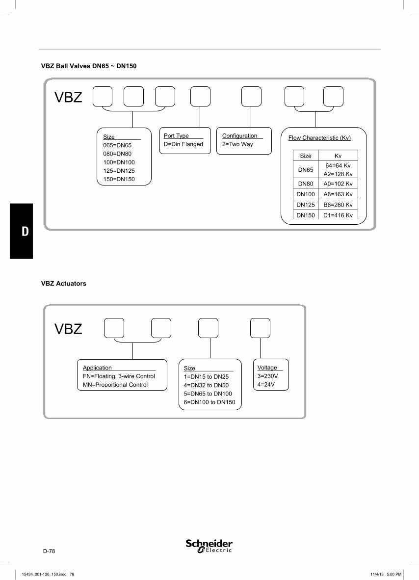
D-78
D
15434_001-130_150.indd 7815434_001-130_150.indd 78 11/4/13 5:00 PM11/4/13 5:00 PM
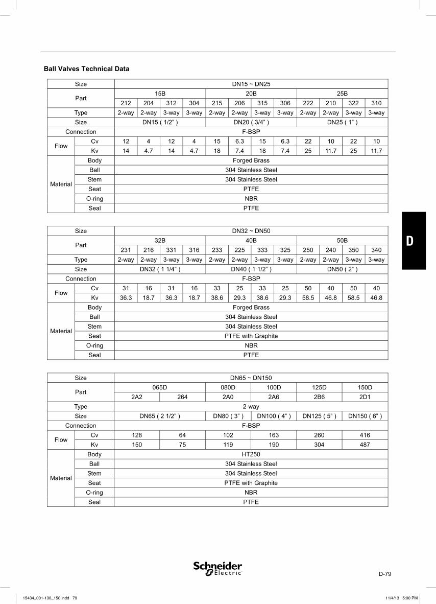
D-79
D
15434_001-130_150.indd 7915434_001-130_150.indd 79 11/4/13 5:00 PM11/4/13 5:00 PM

D-80
D
15434_001-130_150.indd 8015434_001-130_150.indd 80 11/4/13 5:00 PM11/4/13 5:00 PM

D-81
D
15434_001-130_150.indd 8115434_001-130_150.indd 81 11/4/13 5:00 PM11/4/13 5:00 PM

D-82
D
15434_001-130_150.indd 8215434_001-130_150.indd 82 11/4/13 5:00 PM11/4/13 5:00 PM

D-83
D
15434_001-130_150.indd 8315434_001-130_150.indd 83 11/4/13 5:00 PM11/4/13 5:00 PM

D-84
D
15434_001-130_150.indd 8415434_001-130_150.indd 84 11/4/13 5:00 PM11/4/13 5:00 PM

D-85
D
15434_001-130_150.indd 8515434_001-130_150.indd 85 11/4/13 5:00 PM11/4/13 5:00 PM

D-86
D
15434_001-130_150.indd 8615434_001-130_150.indd 86 11/4/13 5:00 PM11/4/13 5:00 PM

D-87
D
15434_001-130_150.indd 8715434_001-130_150.indd 87 11/4/13 5:00 PM11/4/13 5:00 PM

D-88
D
15434_001-130_150.indd 8815434_001-130_150.indd 88 11/4/13 5:00 PM11/4/13 5:00 PM

D-89
D
15434_001-130_150.indd 8915434_001-130_150.indd 89 11/4/13 5:00 PM11/4/13 5:00 PM

D-90
D
15434_001-130_150.indd 9015434_001-130_150.indd 90 11/4/13 5:00 PM11/4/13 5:00 PM

E-91
E
VF208W 25-200NS and VF208W 100-200NZButterfly Valves
Technical Data
The VF208W is a butterfl y valve for the isolation and
control of water for HVAC systems such as boiler
isolation or heat pump change over from cooling to
heating. The butterfl y valves have elongated wafer
type eyelets and are designed to be fi tted between
fl anges . The VF208W can be operated either by an
electric actuator or by hand using a handlever
Valve Features:Energy saving: EPDM soft seats provide •
tight shut off and zero leakage
(Complete insulation possible according to
German energy saving order, EnEV)
Approved for use with drinking water (NS •
types to DVGW).
The VF208W can be operated either by an elec-•
tric actuator or by hand using a handlever
Maintenance free, double sealing of stem, •
centrical disc bearing
Good fl ow control characteristics•
Integrated dew point barrier, •
No linkage kits required•
Ordering Information
Size KvStainless Steel Disc Max P
(kPa)Actuator Handlever
Part Number Full Type Description
DN25 26 VF208W-25NS VF208W-25NS 26E B00 600 MF20 915-0065-000
DN32 26.5 VF208W-32NS VF208W-32NS 26.5E B00 600 MF20 915-0065-000
DN40 50 VF208W-40NS VF208W-40NS 50E B00 600 MF20 915-0065-000
DN50 115 VF208W-50NS VF208W-50NS 115E B00 600 MF20 915-0065-000
DN65 260 VF208W-65NS VF208W-65NS 260E B00 600 MF20 915-0065-000
DN80 375 VF208W-80NS VF208W-80NS 375E B00 600 MF20 915-0100-000
DN100 760 VF208W-100NS VF208W-100NS 760E B00 600 MF20 915-0100-000
DN125 1,025 VF208W-125NS VF208W-125NS 1025E B00 600 MF40 915-0200-000
DN150 1,790 VF208W-150NS VF208W-150NS 1790E B00 300 MF40 915-0200-000
DN200 3450 VF208W-200NS VF208W 200NS 3450E B00 300 MF40 915-0200-000
Size KvNodular Iron Disc Max P
(kPa)
Actuator Handlever
Part Number Full Type Designation
DN100 760 VF208W-100NZ VF208W 100NZ 760E B00 600 MF20 915-0100-000
DN125 1025 VF208W-125NZ VF208W 125NZ 1025E B00 600 MF40 915-0200-000
DN150 1790 VF208W-150NZ VF208W 150NZ 1790E B00 300 MF40 915-0200-000
DN200 3450 VF208W-200NZ VF208W 200NZ 3450E B00 300 MF40 915-0200-000
Shaded items are stocked products•
Contact Technical Support for larger sizes / higher Media temperatures / lugged fl ange connections•
Pressure Class . . . . . . . . . . . . . . . . . . . . . . PN 16Leakage (EN 12266-1) . . Tight, (Leakage Rate A)Temperature Range . . . . . . . . . . . . . -10°C to +100Body . . . . . . . . . . . . . . . . . . . . . . Nodular Iron (EN-JS1030)
Disc (NZ types) . . . . . . . . . . . . . Nodular Iron (EN-JS1030)
Disc (NS types) . . . . . . . . . . . . . St. Steel (AISI316/1.4581)
Stem . . . . . . . . . . . . . . . . . . . . . . . . . . . . . . . . . . . . . 1.4021-QT
15434_001-130_150.indd 9115434_001-130_150.indd 91 11/4/13 5:00 PM11/4/13 5:00 PM

E-92
E
Valve, DN 25 32 40 50 65 80 100 125 150 200
L 33 33 33 43 46 46 52 56 56 60
H 128 128 134 140 150 158 179 196 212 246
E 58 58 66 69 81 100 109 124 140 137
I 15 15 15 15 15 15 15 18 18 18
B 5 5 11 18 25 36 48 71
D 26 29 49 68 88 115 142 194
Actuator MF20 MF40
H1 212 212 218 224 234 242 263 293 309 343
P1 70 69
P2 142 166
P3 95 134
Handlever 915-0065-000 915-0100-000 915-0200-000
P1 184 273
H1 187 187 193 199 209 217 238 263 279 313
DN25-65 DN80-100 DN125-150 DN200
Flange Dimensions and Bolt Hole Sizing
DN 25 32 40 50 65 80 100 125 150 200
øK (mm) 85 100 110 125 145 160 180 210 240 295
n x ød1 (mm) 4x14 4x18 8x18 8x22 12x22
No. of Eyelets 4 8 12
Bolt Dia. M12 M16 M20
Bolt Length (mm) 90 100 110 120 130 140
All dimensions on this page are listed in mm.
Dimensions Handlevers
15434_001-130_150.indd 9215434_001-130_150.indd 92 11/4/13 5:00 PM11/4/13 5:00 PM

E-93
E
Flow Curves
close open
opening angle disc
DN 200
DN 150
DN 100
DN 80
DN 65
DN 50
DN 40
DN25/32
DN 125
Flow Equations
Kv = Q
√ ΔP
Kv √ ΔP Q =
ΔP =Q
Kv( )2
Kv = Flow coeffi cient, m3/h @ 1 bar
Q = Volume Flow rate, m3/h
ΔP = Pressure drop, bar
Flow equations based on fl uid density of 1
15434_001-130_150.indd 9315434_001-130_150.indd 93 11/4/13 5:00 PM11/4/13 5:00 PM

E-94
E
Control Voltage Torque Part Number Type DesignationSuitable VF208W
Valve SizesLiterature
Floating & On/Off 24V AC/DC 20Nm MF20-24F MF20-24F T54 00 DN25-100
F-27639Floating & On/Off 230V AC 20Nm MF20-230F MF20-230F T54 00 DN25-100
0(2)-10V Proportional 24V AC/DC 20Nm MF20-24M MF20-24M T54 00 DN25-100
LON 24V AC/DC 20Nm MF20-24L MF20-24M 1M54 00 DN25-100
Floating & On/Off 24V AC/DC 40Nm MF40-24F MF40-24F T54 00 DN125-200
F-27640Floating & On/Off 230V AC 40Nm MF40-230F MF40-230F T54 00 DN125-200
0(2)-10V Proportional 24V AC/DC 40Nm MF40-24M MF40-24M T54 00 DN125-200
LON 24V AC/DC 40Nm MF40-24L MF40-24M 1M54 00 DN125-200
Recommended Actuators
V -Valve Type: F - Butterfly
Number of Ports: 2 - Two Way
Actuator Connection: 8 - MF20 / MF40
Flow Control: 0 - Uncharacterized flow
Connection Type: W - Flanged Wafer
Orifice Size: 25 - 25 mm32 - 32 mm40 - 40 mm50 - 50 mm100 - 100mm125 - 125 mm150 - 150 mm200 - 200 mm
Body/Disc NS - Nodular Iron Body, SS discNZ - Nodular Iron Body, zinc-lamella coated disc
V -Valve Type
Number of Ports
Actuator Connection
Flow Control
Connection Type
Orifice Size
Body/Disc
Kv: 26 - 26 Kv26.5 - 26.5 Kv50 - 50 Kv115 - 115 Kv260 - 260 Kv375 - 375 Kv760 - 760 Kv1025 - 1025 Kv1790 - 1790 Kv
Seal:
E - EDPM
Handwheel/Gearbox:
B- Bare
Options
and
Specials
Type Designation
Main Type Specification Code
Part Number
Type Designation and Part Number
15434_001-130_150.indd 9415434_001-130_150.indd 94 11/4/13 5:00 PM11/4/13 5:00 PM

E-95
E
MF20 Butterfly Valve ActuatorThe MF20 is a robust, reliable rotary actuator for the control of the VF208W 25-100 butterfl y valves. These actuators mount to the VF208W se-ries valves without linkage kits and connect using electrical terminal blocks to simplify and reduce installation time.
Features:Models for Floating/Proportional • and On/Off controlLatching Manual override• Direct Hand Lever / position indicator• No Linkage kits required•
Technical Data
Product MF20-24F MF20-24M MF20-24L MF20-230F
Description3-Point Floating,
24V2-10 V Modulating LON 3-Point Floating, 230V
Torque (nominal) Min. 20 Nm at nominal voltage
Motor Voltage 24Vac±20% 50/60 Hz or 24 Vdc±20% 230 VA -60%/+15%, 50/60 Hz
Power Consumption:
Operation2.5 W 2.5 W 3.5 W 3 W
Power Consumption:
At Rest0.2 W 0.4 W 1.25 W 0.4 W
Power Consumption:
For wire sizing5.5 Vac 5 Vac 6 Vac 7 Vac
Electrical Connection
Terminals 4 mm2
(Cable ø 6... 8 mm,
three-core)
Terminals 4 mm2
(Cable ø 6... 8 mm,
four-core)
Cable 1 m, 6 x 0.75
mm2
Terminals 4 mm2 (Cable ø 6... 8 mm,
three-core)
Control: SignalOpen/Close or
3-Point,
DC 0 ... 10 V, typical
input impedance
100 kΩ
Open/Close or 3-Point,
Control: Operating
Range– DC 2 ... 10 V –
Position Feedback
(Measuring voltage U)–
DC 2 ... 10 V, max.
1 mA
DC 2 ... 10 V,
max. 0.5 mA–
Position Accuracy – ±5% –
Sound power level Max. 45 dB (A)
Operating Time 90 s/90°
EMC CE according to 89/336/EEC
CE according to 89/336/EECLow voltage directive CE ac-cording to 73/23/EWG
Rated impulse volt-age
0.8 kV (to EN 60730-1) 4 kV (to EN 60730-1)
Enclosure IP 54
Protection Class III Extra Low Voltage II Total Insulated
Max Ambient Temp. 0 to 50°C
15434_001-130_150.indd 9515434_001-130_150.indd 95 11/4/13 5:00 PM11/4/13 5:00 PM

E-96
E
Voltage Control Torque Part Number Type DesignationSuitable VF208W
Valve Sizes
24V AC/DC Floating & On/Off 20Nm MF20-24F MF20-24F-T54 00 DN25-100
230V AC Floating & On/Off 20Nm MF20-230F MF20-230F-T54 00 DN25-100
24V AC/DC 0(2)-10V Proportional 20Nm MF20-24M MF20-24M T54 00 DN25-100
24V AC/DC LON 20Nm MF20-24L MF20-24M 1M54 00 DN25-100
Shaded items are stocked products.
Ordering Information
M -
Type Designation
Part Number
Valve Type: F - Butterfly
Voltage: 24 - 24 Vac230 - 230 Vac
Control:F - FloatingM - Modulating
Enclosure54 - IP54
Electrical ConnectionT - Terminal Block1M - One Meter CableForce:
20 - 20 Nm40 - 40 Nm
M -Voltage ControlForce
Options and Specials
Main TypeVariationActuator Family
Specification Code
Type Designation and Part Number
Literature Directory
Product Description Document Number
VF208W 25-200 DN DN 25-200 Butterfl y valve datasheet F-27638
VF208W 200-500 DN DN 200-500 Butterfl y valve datasheet In Development
MF40 Actuator MF40 Datasheet F-27640
MF20/MF40 Installation Instruction 0FL-4413-000
Accessories
Type Description Rating Part Number
MD-S1 1xSPDT auxiliary switchAC1: 1mA to 3A, 250V
(AC3: Max 0.5A)914-1060-000
MD-S2 2xSPDT auxiliary switchAC1: 1mA to 3A, 250V
(AC3: Max 0.5A)914-1061-000
15434_001-130_150.indd 9615434_001-130_150.indd 96 11/4/13 5:00 PM11/4/13 5:00 PM

E-97
E
Actuator Dimensions
MF20-24L
MF20-24F, MF20-24M, and MF20-230F
15434_001-130_150.indd 9715434_001-130_150.indd 97 11/4/13 5:00 PM11/4/13 5:00 PM

E-98
E
AC 24 V / DC 24 V
1 2 3 5
– +
T ~ X1 Input Signal X1 DC (0) 2 ... 10 V Y Feedback Signal Y DC 2 ... 10 V
G0 G
N L1
1 2 3
– +
T ~ G0 G
10
1 2 3
0
N L1 – +
T ~ G0 G
10
AC 24 V / DC 24 V
1 2 3
– +
T ~
+
~G0 VH VC AC 100 ... 240 V N L1 L2
1 2 3
!
L ON W ORKS ® AC 24 V / DC 24 V
5 6 73 2 1
MFT
LON
LON
T ~
V
5 6 73 2 1
MFT
LON
LON
+–
T ~
5 6 73 2 1
MFT
LON
LON
+–
T ~
Δp
5 6 73 2 1
MFT
LON
LON
+–
T ~
1
0
MF20-24F MF20-230F
MF20-24M
MF20-24L
Wiring Diagrams
Assembly Dimensions
DN 25 32 40 50 65 80 100
H1 212 212 218 224 234 242 263
P1 70
P2 142*
P3 95
Dimensions in mm.
* MF20-24L - 172mm
15434_001-130_150.indd 9815434_001-130_150.indd 98 11/4/13 5:00 PM11/4/13 5:00 PM

E-99
E
MF40 Butterfly Valve ActuatorThe MF40 is a robust, reliable rotary actuator for the control of the VF208W 125-200 butterfl y valves. These actuators mountto the VF208W series valves without linkage kits and connect using electrical terminal blocks to simplify and reduce installation time.
Features:Models for Floating / Proportional • and On/Off controlLatching Manual override• Direct Hand Lever / position indicator• No Linkage kits required•
Technical Data
Product MF40-24F MF40-24M MF40-24L MF40-230F
Description 3-Point Floating, 24V 2-10 V Modulating LON 3-Point Floating, 230V
Torque (nominal) Min. 40 Nm at nominal voltage
Motor Voltage 24Vac±20% 50/60 Hz or 24 Vdc±20%230 VA -60%/+15%,
50/60 Hz
Power Consumption:
Operation4 W 4.5 W 4 W 5 W
Power Consumption:
At Rest2 W 1.5 W 1.5 W 2 W
Power Consumption:
For wire sizing6 VA 6.5 VA 7 VA 9 VA
Electrical Connection
Terminals 4 mm2
(Cable ø 6... 8 mm,
three-core)
Terminals 4 mm2
(Cable ø 6... 8 mm,
four-core)
Cable 1 m, 6 x
0.75 mm2
Terminals 4 mm2
(Cable ø 6... 8 mm,
three-core)
Control: SignalOpen/Close or
3-Point,
DC 0 ... 10 V, typical
input impedance
100 kΩ
Open/Close or 3-Point,
Control: Operating Range – DC 2 ... 10 V –
Position Feedback
(Measuring voltage U)–
DC 2 ... 10 V, max.
1 mA
DC 2 ... 10 V,
max. 0.5 mA–
Position Accuracy – ±5% –
Sound power level Max. 45 dB (A)
Operating Time 150 s/90° 90 s/90° 150 s/90°
EMC CE according to 89/336/EEC
CE according to
89/336/EEC
Low voltage directive
CE according to 73/23/
EWG
Rated impulse voltage 0.8 kV (to EN 60730-1) 4 kV (to EN 60730-1)
Enclosure IP 54
Protection Class III Extra Low Voltage II Total Insulated
Max Ambient Temp. 0 to 50°C
15434_001-130_150.indd 9915434_001-130_150.indd 99 11/4/13 5:00 PM11/4/13 5:00 PM

E-100
E
Control Voltage Torque Part Number Full Type DesignationSuitable VF208W
Valve Sizes
Floating & On/Off 24V AC/DC 40Nm MF40-24F MF40-24F-T54 00 DN125-200
Floating & On/Off 230V AC 40Nm MF40-230F MF40-230F-T54 00 DN125-200
0(2)-10V Proportional 24V AC/DC 40Nm MF40-24M MF40-24M T54 00 DN125-200
LON 24V AC/DC 40Nm MF40-24L MF40-24M T1M54 00 DN125-200
Shaded items are stocked products.
Ordering Information
Type Designation and Part Number
Accessories
Type Description Rating Part Number
MD-S1 1xSPDT auxiliary switchAC1: 1mA to 3A, 250V
(AC3: Max 0.5A)914-1060-000
MD-S2 2xSPDT auxiliary switchAC1: 1mA to 3A, 250V
(AC3: Max 0.5A)914-1061-000
Type Designation
Literature Directory
Product Description Document Number
VF208W 25-200 DN DN 25-200 Butterfl y valve datasheet F-27638
VF208W 200-500 DN DN 200-500 Butterfl y valve datasheet In development
MF20 Actuator MF20 Datasheet F-27639
MF20/MF40 Installation Instruction 0FL-4413-000
M -
Part Number
Valve Type: F - Butterfly
Voltage: 24 - 24 Vac230 - 230 Vac
Control:F - FloatingM - ModulatingForce:
20 - 20 Nm40 - 40 Nm
M -Voltage ControlForce
Main TypeVariationActuator Family
Enclosure54 - IP54
Electrical ConnectionT - Terminal Block1M - One Meter Cable
Options and Specials
Specification Code
15434_001-130_150.indd 10015434_001-130_150.indd 100 11/4/13 5:00 PM11/4/13 5:00 PM

E-101
E
Dimensions
MF40-24L
MF40-24F, MF40-24M, and M420-230F
15434_001-130_150.indd 10115434_001-130_150.indd 101 11/4/13 5:00 PM11/4/13 5:00 PM

E-102
E
AC 24 V / DC 24 V
1 2 3 5
– +
T ~ X1 Input Signal X1 DC (0) 2 ... 10 V Y Feedback Signal Y DC 2 ... 10 V
G0 G
MF40-24M
1 2 3
10
1 2 3
0
10
AC 24 V / DC 24 V
1 2 3
– +
T ~
+
~G0 VH VC
MF40-24F
AC 100 ... 240 V N L1 L2
1 2 3
MF40-230F
!
L ON W ORKS ® AC 24 V / DC 24 V
5 6 73 2 1
MFT
LON
LON
T ~
V
5 6 73 2 1
MFT
LON
LON
+–
T ~
5 6 73 2 1
MFT
LON
LON
+–
T ~
Δp
5 6 73 2 1
MFT
LON
LON
+–
T ~
MF40-24L
1
0
Wiring Diagrams
DN 125 150 200
H1 293 309 343
P1 69
P2 175*
P3 124
Dimensions in mm.
* MF40-24L - 184mm
Assembly Dimensions
15434_001-130_150.indd 10215434_001-130_150.indd 102 11/4/13 5:00 PM11/4/13 5:00 PM

F-103
F
LF24/LF230
SPECIFICATIONSPart number
LF24 . . . . . . . . . . . . . . . . . . . . . . . . .874-0003-000
LF230 . . . . . . . . . . . . . . . . . . . . . . . .875-0003-000
Power supply
LF24 . . . . . . . . . . . . . . . 24 V AC ±20%, 50–60 Hz,
24 V DC -10%, +20%
LF230 . . . . . . . . . . . . . . 230 V AC ±14%, 50–60 Hz
Power consumption
LF24, opening . . . . . . . . . . . . . . . . . . . . . . . . . 5 W
LF24, open . . . . . . . . . . . . . . . . . . . . . . . . . . 2.5 W
LF230, opening . . . . . . . . . . . . . . . . . . . . . . . . 5 W
LF230, open . . . . . . . . . . . . . . . . . . . . . . . . . . . 3 W
For wire sizing
LF24 . . . . . . . . . . . . . . . . .7 VA (Imax=5.8 A for 5 ms)
LF230 . . . . . . . . . . . . .7 VA (Imax=150 mA for 10 ms)
Connection cable . . . . . . .1 m (3.3 ft), 2×0.75 mm2
(AWG 18)
Angle of rotation . . . . . . . . . . . . . . . . . . . . max. 95°
(adjustable 37–100% S with additional limit stop ZDB-LF)
Torque
Actuator . . . . . min. 4 Nm (3 ft-lbf) (at rated voltage)
Spring return . . . . . . . . . . . . . . .min. 4 Nm (3 ft-lbf)
Running time
Actuator . . . . . . . . . . . 40–75 s (0–4 Nm (0–3 ft-lbf))
Spring Return Actuator for Open/Close Damper Actuation 4 Nm (3 ft-lbf)
The LF24 and LF230 open/close spring return actuators are intended for operation of air damp-ers of up to approximately 0.8 m2 (8.6 ft2) cross sectional area that perform safety functions, e.g. frost and smoke protection, hygiene, etc.
Either direction of rotation can be selected.
The spring return operates as a safety function if the power supply fails or is interrupted. The spring pretensioning can be manually adjusted.
Spring return . . . . . .approx. 20 s (at -20 to +50 °C
(-4 to +122°F)), max. 60 s (at -30 °C (-22°F))
Direction of rotation . . . . selected by mounting L/R
Position indication . . . . . . . . . . . . . . . . mechanical
Standards conformity EMC . . . . . . . . . . . . . . . . . . . . . . . . . 2004/108/EC
LVD . . . . . . . . . . . . . . . . . 2006/95/EC (230 V only)
Protection class
LF24 . . . . . . . . . . . . . . . III (safety extra-low voltage)
LF230 . . . . . . . . . . . . . . . . . . . . . . . . II (all insulated)
Enclosure rating . . . . . . . . . . . . . . . . . . . . . . . IP 54
Ambient humidity . . . . . . . . . . . . . . . . EN 60730-1
Ambient temperature
Operation . . . . . . . . –30 to +50 °C (–22 to +122 °F)
Storage . . . . . . . . –40 to +80 °C (–40 to +176 °F)
Sound power level
Actuator . . . . . . . . . . . . . . . . . . . . . max. 50 dB (A)
Spring . . . . . . . . . . . . . . . . . . . . approx. 62 dB (A)
Service life . . . . . . . . . . . . . min. 60 000 operations
Maintenance . . . . . . . . . . . . . . . . .maintenance-free
Weight
LF24 . . . . . . . . . . . . . . . . . . . . . . . . . 1.4 kg (3.1 lb.)
LF230 . . . . . . . . . . . . . . . . . . . . . . . 1.55 kg (3.4 lb.)
15434_001-130_150.indd 10315434_001-130_150.indd 103 11/4/13 5:00 PM11/4/13 5:00 PM

F-104
F
WIRING
LF24: Connect via safety isolating transformer.
LF230: To isolate from the main power supply, the system must incorporate a device which provides all-pole discon-nection (with at least a 3 mm (0.12 in.) contact gap).
Parallel connection of several actua-tors is possible. Power consumption must be observed.
!WIRING
DIMENSIONS mm (in)
MODE OF OPERATION
The actuator is fitted with a universal spindle clamp for quick and easy mounting directly onto the damper spindle. The actuator is also supplied with an anti-rotation strap for fixing it in position. The direction of rotation is selected by mounting left or right.
The actuator is used for open/close control by single-wire system.
The actuator has a mechanical angle of rotation limiting, adjustable with an additional limit stop.
The actuator moves the damper to its normal working position while tensioning the return spring at the same time.
If the power supply is interrupted, the energy stored in the spring moves the damper back to its safe position ≤ 0°.
The actuator is overload-proof and needs no limit switches. It stops automatically at the end stops.
NOTE
When calculating the torque required to operate dampers, it is essential to take into account all the data supplied by the damper manufacturer concerning cross sectional area, design, mount-ing and air flow conditions.
ACCESSORIES
Please refer to data sheet G-30-90 “Accessories Damper Actuators” (part. no. 0-003-2251).
15434_001-130_150.indd 10415434_001-130_150.indd 104 11/4/13 5:00 PM11/4/13 5:00 PM
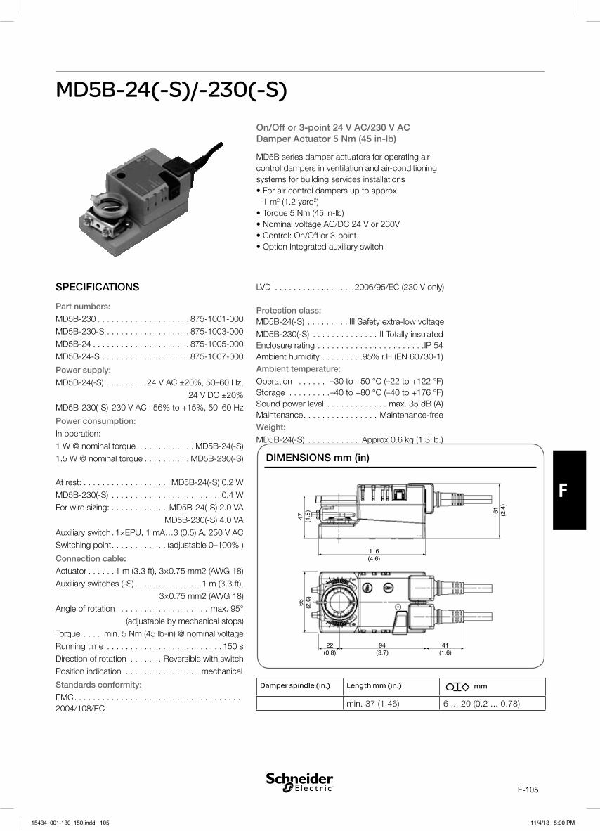
F-105
F
MD5B-24(-S)/-230(-S)
SPECIFICATIONS
Part numbers:
MD5B-230 . . . . . . . . . . . . . . . . . . . . 875-1001-000
MD5B-230-S . . . . . . . . . . . . . . . . . . 875-1003-000
MD5B-24 . . . . . . . . . . . . . . . . . . . . . 875-1005-000
MD5B-24-S . . . . . . . . . . . . . . . . . . . 875-1007-000
Power supply:
MD5B-24(-S) . . . . . . . . .24 V AC ±20%, 50–60 Hz,
24 V DC ±20%
MD5B-230(-S) 230 V AC –56% to +15%, 50–60 Hz
Power consumption:
In operation:
1 W @ nominal torque . . . . . . . . . . . . MD5B-24(-S)
1.5 W @ nominal torque . . . . . . . . . . MD5B-230(-S)
At rest: . . . . . . . . . . . . . . . . . . . MD5B-24(-S) 0.2 W
MD5B-230(-S) . . . . . . . . . . . . . . . . . . . . . . . 0.4 W
For wire sizing: . . . . . . . . . . . . MD5B-24(-S) 2.0 VA
MD5B-230(-S) 4.0 VA
Auxiliary switch . 1×EPU, 1 mA…3 (0.5) A, 250 V AC
Switching point . . . . . . . . . . . . (adjustable 0–100% )
Connection cable:
Actuator . . . . . . 1 m (3.3 ft), 3×0.75 mm2 (AWG 18)
Auxiliary switches (-S) . . . . . . . . . . . . . . 1 m (3.3 ft),
3×0.75 mm2 (AWG 18)
Angle of rotation . . . . . . . . . . . . . . . . . . . max. 95°
(adjustable by mechanical stops)
Torque . . . . min. 5 Nm (45 lb-in) @ nominal voltage
Running time . . . . . . . . . . . . . . . . . . . . . . . . . 150 s
Direction of rotation . . . . . . . Reversible with switch
Position indication . . . . . . . . . . . . . . . . mechanical
Standards conformity:
EMC . . . . . . . . . . . . . . . . . . . . . . . . . . . . . . . . . . . . 2004/108/EC
On/Off or 3-point 24 V AC/230 V ACDamper Actuator 5 Nm (45 in-lb)
MD5B series damper actuators for operating air control dampers in ventilation and air-conditioning systems for building services installations
1 m2 (1.2 yard2)
LVD . . . . . . . . . . . . . . . . . 2006/95/EC (230 V only)
Protection class:MD5B-24(-S) . . . . . . . . . III Safety extra-low voltage
MD5B-230(-S) . . . . . . . . . . . . . . II Totally insulatedEnclosure rating . . . . . . . . . . . . . . . . . . . . . . .IP 54Ambient humidity . . . . . . . . .95% r.H (EN 60730-1)Ambient temperature:
. . . . . . –30 to +50 °C (–22 to +122 °F)Storage . . . . . . . . .–40 to +80 °C (–40 to +176 °F)Sound power level . . . . . . . . . . . . . max. 35 dB (A)Maintenance . . . . . . . . . . . . . . . . Maintenance-freeWeight:
MD5B-24(-S) . . . . . . . . . . . Approx 0.6 kg (1.3 lb.)
DIMENSIONS mm (in)
47 (1.8
) 61 (2.4
)
66 (2.6
)
22(0.8)
94(3.7)
41(1.6)
116(4.6)
Damper spindle (in.) Length mm (in.) mm
min. 37 (1.46) 6 ... 20 (0.2 ... 0.78)
15434_001-130_150.indd 10515434_001-130_150.indd 105 11/4/13 5:00 PM11/4/13 5:00 PM

F-106
F
WIRING
0
1
1 2 3
10
0...100%
S1 S2 S3
On/Off controlN L1
1 2 3
0...100%
S1 S2 S3
0
10
3-point controlN L1
1 2 3
10
0...100%
S1 S2 S3
On/Off controlG0 G
1 2 3
0...100%
S1 S2 S3
0
10
3-point controlG0 G
S1 S2 S31
0
1
0
S1 S2 S31
0
Auxilary switch
Direction of rotation
WIRINGMD5B-230(-S)
Caution: 230 V voltage!
Please note the performance data.
MD5B-24(-S)
Connection via safety isolating transformer!
Please note the performance data.
FUNCTION
Simple direct mountingSimple direct mounting on the damper spindle with a universal spindle clamp, supplied with an anti-rotation strap to prevent the actuator from rotating.
Manual override Manual operation is possible with the self-resetting pushbutton (the gearing latch remains disengaged as long as the pushbutton is pressed or detented).
Adjustable angle of rotation Adjustable angle of rotation with mechanical end stops.
High functional reliability The actuator is overload-proof, requires no limit switches and automatically stops when the end stop is reached.
Flexible signalization Flexible signalization with adjustable auxiliary switch (0 ... 100%).
ACCESSORIES
Please refer to data sheet G-30-90
“Accessories Damper Actuators” (part.no. 0-003-2251).
SAFETY NOTES
The damper actuator is not allowed to be used outside the specified field of application, especially in aircraft.
Caution: 230 V voltage !
The device may only be opened at the manufacturer’s site. It does not con-tain any parts that can be replaced or repaired by the user.
The cables must not be removed from the device.
When calculating the required torque, the specifications supplied by the damper manufacturers (cross section, design, installation site), and the air flow conditions must be observed.
The device contains electrical and electronic components and is not al-lowed to be disposed of as household refuse. All locally valid regulations and requirements must be observed.
!
!
!
15434_001-130_150.indd 10615434_001-130_150.indd 106 11/4/13 5:00 PM11/4/13 5:00 PM

F-107
F
MD5A-24
SPECIFICATIONS
Part number . . . . . . . . . . . . . . . . . . . 875-1009-000
Power supply . . . . . . . . .24 V AC ±20%, 50–60 Hz,
24 V DC ±20%
Power consumption
In operation . . . . . . . . . . . . . 1 W @ nominal torque
At rest . . . . . . . . . . . . . . . . . . . . . . . . . . . . . .0.4 W
For wire sizing . . . . . . . . . . . . . . . . . . . . . . . . . .2 VA
Connection cable . . . . . . . 1 m (3.3 ft), 4×0.75 mm2
(AWG 18)
Control signal X . . . . . . . . . . . . . . . . . . .0–10 V DC
Input resistance . . . . . . . . . . . . . . . . . . 100 k Ohm
Operating range 2–10 V DC (for set angle of rotation)
Synchronisation tolerance . . . . . . . . . . . . . . . .±5%
Position feedback Y . . . . . . 2–10 V DC (max. 1 mA)
Direction of rotation . . . Reversible with switch 0 / 1
at switch position 0 resp 1
Angle of rotation . . . . . . . . . . . . . . . . . . . . max. 95°
(adjustable by mechanical stops)
Torque . . . . min. 5 Nm (45 in-lb) @ nominal voltage
Running time . . . . . . . . . . . . . . . . . . . . . . . . . 150 s
Position indication . . . . . . . . . . . . . . . . mechanical
Manual override . . . .Gearing latch disengaged with
pushbutton, self-resetting, manual locking
Standards conformity
EMC . . . . . . . . . . . . . . . . . . . . . . . . . . . . . . . . . . . . 2004/108/ECLVD . . . . . . . . . . . . . . . . . 2006/95/EC (230 V only)Protection class . . . . . . . III Safety extra-low voltage
Enclosure rating . . . . . . . . . . . . . . . . . . . . . . . IP 54
Modulating Damper Actuator Action 5 Nm (45 in-lb)
MD5A-24 damper actuators for operating air control dampers in ventilation and air-conditioning systems for building services installations
2 (1.2 yard2)
DIMENSIONS mm (in)
47 (1.8
) 61 (2.4
)
66 (2.6
)
22(0.8)
94(3.7)
41(1.6)
116(4.6)
Damper spindle (in.) Length mm (in.) mm
min. 37 (1.46) 6 ... 20 (0.20 ... 0.78)
Ambient humidity . . . . . . . . . 95% r.H (EN 60730-1)
Ambient temperature
Operation . . . . . . . . –30 to +50 °C (–22 to +122 °F)
Storage . . . . . . . . . –40 to +80 °C (–40 to +176 °F)
Sound power level . . . . . . . . . . . . . .max. 35 dB (A)
Maintenance . . . . . . . . . . . . . . . . .Maintenance-free
Weight . . . . . . . . . . . . . . . . . Approx 0.5 kg (1.3 lb.)
15434_001-130_150.indd 10715434_001-130_150.indd 107 11/4/13 5:00 PM11/4/13 5:00 PM

F-108
F
FUNCTION
Mode of operationThe actuator is controlled by means of a standard control signal DC 2-10 V. It opens to the position dictated by this signal. The measuring voltage Y allows the damper position (0 ... 100%) to be electrically indicated and serves as a follow-up control signal for other actuators.
Simple direct mountingSimple direct mounting on the damper spindle with a universal spindle clamp, supplied with an anti-rotation strap to prevent the actuator from rotating.
Manual override Manual operation is possible with the self-resetting pushbutton (the gearing latch remains disengaged as long as the pushbutton is pressed or detented).
Adjustable angle of rotation Adjustable angle of rotation with mechanical end stops.
High functional reliability The actuator is overload-proof, requires no limit switches and automatically stops when the end stop is reached.
WIRING Connection via safety isolating transformer!
Measuring voltage Y for position indication or as master-slave signal.
Parallel connection of several actuators is pos-sible. Power consumption must be observed.
ACCESSORIES
Please refer to data sheet G-30-90
“Accessories Damper Actuators” (part.no. 0-003-2251).
!
!
WIRING
SAFETY NOTES
The damper actuator is not allowed to be used outside the specified field of application, especially in aircraft.
The device may only be opened at the manufacturer’s site. It does not con-tain any parts that can be replaced or repaired by the user.
The cable must not be removed from the device.
When calculating the required torque, the specifications supplied by the damper manufacturers (cross section, design, installation site), and the air flow conditions must be observed.
The device contains electrical and electronic components and is not al-lowed to be disposed of as household refuse. All locally valid regulations and requirements must be observed.
24 V ACGG0
1 2 3 5
G0 G X1 Y
X1 0-10 V DCY 2-10 V DC
15434_001-130_150.indd 10815434_001-130_150.indd 108 11/4/13 5:00 PM11/4/13 5:00 PM

F-109
F
MD10B-24/-230
SPECIFICATIONS
Part numbers
MD10B-230 . . . . . . . . . . . . . . . . . . . 875-1011-000
MD10B-24 . . . . . . . . . . . . . . . . . . . . 875-1015-000
Power supply
MD10B-24 . . . . . . . . . . .24 V AC ±20%, 50–60 Hz,
24 V DC ±20%
MD10B-230 . . 230 V AC –56% to +15%, 50–60 Hz
Power consumption
In operation
MD10B-24 . . . . . . . . . . . . .1.5 W @ nominal torque
MD10B-230 . . . . . . . . . . . .2.5 W @ nominal torque
At rest
MD10B-24 . . . . . . . . . . . . . . . . . . . . . . . . . . .0.2 W
MD10B-230 . . . . . . . . . . . . . . . . . . . . . . . . . .0.6 W
For wire sizing
MD10B-24 . . . . . . . . . . . . . . . . . . . . . . . . . 3.5 VA
MD10B-230 . . . . . . . . . . . . . . . . . . . . . . . . . 5.5 VA
Connection cable . . . . . . . 1 m (3.3 ft), 3×0.75 mm2
(AWG 18)
Angle of rotation . . . . . . . . . . . . . . . . . . . . max. 95°
(adjustable by mechanical stops)
Torque . . . min. 10 Nm (90 iin-lb) @ nominal voltage
Running time . . . . . . . . . . . . . . . . . . . . . . . . . 150 s
Direction of rotation . . . . . . . Reversible with switch
Position indication . . . . . . . . . . . . . . . . mechanical
Standards conformity
EMC . . . . . . . . . . . . . . . . . . . . . . . . . . . . . . . . . . . . 2004/108/ECLVD . . . . . . . . . . . . . . . . . 2006/95/EC (230 V only)Protection class
MD10B-24 . . . . . . . . . . . III Safety extra-low voltage
MD10B-230 . . . . . . . . . . . . . . . . . II Totally insulated
On/Off or 3-point 24 V AC/230 V ACDamper Actuator 10 Nm (90 in-lb)
MD10B series damper actuators for operating air control dampers in ventilation and air-conditioning systems for building services installations
2 (2.4 yard2)
Enclosure rating . . . . . . . . . . . . . . . . . . . . . . . IP 54
Ambient humidity . . . . . . . . . 95% r.H (EN 60730-1)
. . . . . . . .
Storage . . . . . . . . .
Sound power level . . . . . . . . . . . . . .max. 35 dB (A)
Maintenance . . . . . . . . . . . . . . . . Maintenance-free
Weight
MD10B-24 . . . . . . . . . . . . . Approx 0.75 kg (1.7 lb.)
MD10B-230 . . . . . . . . . . . . Approx 0.75 kg (1.7 lb.)
DIMENSIONS mm (in)
52(2
.05)
62 (2.4
)
80 (3.1
)
124(4.9)
99(3.9)
25(1.0)
41(1.6)
Damper spindle (in.) Length mm (in.) mm
Clamp on top min. 40 (1.57) 8 ... 26.7 (0.31 ... 1.04)
Clamp on bottom* min. 20 (0.78) 8 ... 20 (0.31 ... 0.78)
15434_001-130_150.indd 10915434_001-130_150.indd 109 11/4/13 5:00 PM11/4/13 5:00 PM

F-110
F
WIRING
0
1
On/Off controlG0 G
1 2 3
01
0
1 2 3
01
3-point controlG0 G
On/Off controlN L1
1 2 3
01
0
3-point controlN L1
1 2 3
01
Direction of rotation
WIRINGMD10B-230
Caution: 230 V voltage!
Please note the performance data.
MD10B-24
Connection via safety isolating transformer!
Please note the performance data.
FUNCTION
Simple direct mountingSimple direct mounting on the damper spindle with a universal spindle clamp, supplied with an anti-rotation strap to prevent the actuator from rotating.
Manual override Manual operation is possible with the self-resetting pushbutton (the gearing latch remains disengaged as long as the pushbutton is pressed or detented).
Adjustable angle of rotation Adjustable angle of rotation with mechanical end stops.
High functional reliability The actuator is overload-proof, requires no limit switches and automatically stops when the end stop is reached.
SAFETY NOTES
The damper actuator is not allowed to be used outside the specified field of application, especially in aircraft-
Caution: 230 V voltage !
The device may only be opened at the manufacturer’s site. It does not con-tain any parts that can be replaced or repaired by the user.
The cables must not be removed from the device.
When calculating the required torque, the specifications supplied by the damper manufacturers (cross section, design, installation site), and the air flow conditions must be observed.
The device contains electrical and electronic components and is not al-lowed to be disposed of as household refuse. All locally valid regulations and requirements must be observed.
ACCESSORIES
Please refer to data sheet G-30-90
“Accessories Damper Actuators” (part. no. 0-003-2251).
!
!
!
15434_001-130_150.indd 11015434_001-130_150.indd 110 11/4/13 5:00 PM11/4/13 5:00 PM

F-111
F
MD10A-24
SPECIFICATIONSPart number . . . . . . . . . . . . . . . . . . . 875-1019-000
Power supply . . . . . . . . .24 V AC ±20%, 50–60 Hz,
24 V DC ±20%
Power consumption
In operation . . . . . . . . . . . . . 2 W @ nominal torque
At rest . . . . . . . . . . . . . . . . . . . . . . . . . . . . . .0.4 W
For wire sizing . . . . . . . . . . . . . . . . . . . . . . . . . .4 VA
Connection cable . . . . . . . 1 m (3.3 ft), 4×0.75 mm2
(AWG 18)
Control signal X . . . . . . . . . . . . . . . . . . .0–10 V DC
Input resistance . . . . . . . . . . . . . . . . . . 100 k Ohm
Operating range . . . . . . . . . . . . . . . . . . .2–10 V DC
(for set angle of rotation)
Synchronisation tolerance . . . . . . . . . . . . . . . . .±5%
Position feedback Y . . . . . . 2–10 V DC (max. 1 mA)
Direction of rotation . . . Reversible with switch 0 / 1
at switch position 0 resp. 1
Angle of rotation . . . . . . . . . . . . . . . . . . . . max. 95°
(adjustable by mechanical stops)
Torque . . . min. 10 Nm (90 in-lb) @ nominal voltage
Running time . . . . . . . . . . . . . . . . . . . . . . . . . 150 s
Position indication . . . . . . . . . . . . . . . . mechanical
Manual override . . . . . . . Gearing latch disengaged
with pushbutton, self-resetting, manual locking
Standards conformity
EMC . . . . . . . . . . . . . . . . . . . . . . . . . . . . . . . . . . . . 2004/108/ECLVD . . . . . . . . . . . . . . . . . 2006/95/EC (230 V only)Protection class . . . . . . . III Safety extra-low voltage
Enclosure rating . . . . . . . . . . . . . . . . . . . . . . . IP 54
Modulating Damper Actuator Damper Actuator 10 Nm (90 in-lb)
MD10A-24 damper actuators for operating air control dampers in ventilation and air-conditioning systems for building services installations
2 (2.4 yard2)
Ambient humidity . . . . . . . . . 95% r.H (EN 60730-1)
Ambient temperature
Operation . . . . . . . . –30 to +50 °C (–22 to +122 °F)
Storage . . . . . . . . . –40 to +80 °C (–40 to +176 °F)
Sound power level . . . . . . . . . . . . . .max. 35 dB (A)
Maintenance . . . . . . . . . . . . . . . . .Maintenance-free
DIMENSIONS mm (in)
52(2
.05)
62 (2.4
)
80 (3.1
)
124(4.9)
99(3.9)
25(1.0)
41(1.6)
Damper spindle (in.) Length mm (in.) mm
Clamp on top min. 40 (1.57) 8 ... 26.7 (0.31 ... 1.04
Clamp on bottom* min. 20 (0.78) 8 ... 20 (0.31 ... 0.78)
*Option (Accessory K-MD10)
15434_001-130_150.indd 11115434_001-130_150.indd 111 11/4/13 5:00 PM11/4/13 5:00 PM

F-112
F
FUNCTION
Mode of operationThe actuator is controlled by means of a standard control signal DC 2-10 V. It opens to the position dictated by this signal. The measuring voltage Y allows the damper position (0 ... 100%) to be electrically indicated and serves as a follow-up control signal for other actuators.
Simple direct mountingSimple direct mounting on the damper spindle with a universal spindle clamp, supplied with an anti-rotation strap to prevent the actuator from rotating.
Manual override Manual operation is possible with the self-resetting pushbutton (the gearing latch remains disengaged as long as the pushbutton is pressed or detented).
Adjustable angle of rotation Adjustable angle of rotation with mechanical end stops.
High functional reliability The actuator is overload-proof, requires no limit switches and automatically stops when the end stop is reached.
WIRING
Connection via safety isolating transformer.
Measuring voltage Y for position indication or as master-slave signal.
Parallel connection of several actuators is possible. Power consumption must be observed.
ACCESSORIES
Please refer to data sheet G-30-90
“Accessories Damper Actuators” (part. no. 0-003-2251).
!
!
WIRING
SAFETY NOTES
The damper actuator is not allowed to be used outside the specified field of application, especially in aircraft.
The device may only be opened at the manufacturer’s site. It does not contain any parts that can be replaced or repaired by the user.
The cable must not be removed from the device.
When calculating the required torque, the specifications supplied by the damper manufacturers (cross section, design, installation site), and the air flow conditions must be observed.
The device contains electrical and electronic components and is not al-lowed to be disposed of as household refuse. All locally valid regulations and requirements must be observed.
15434_001-130_150.indd 11215434_001-130_150.indd 112 11/4/13 5:00 PM11/4/13 5:00 PM
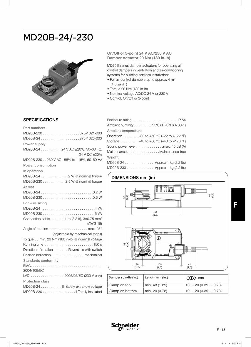
F-113
F
MD20B-24/-230
SPECIFICATIONS
Part numbers
MD20B-230 . . . . . . . . . . . . . . . . . . . 875-1021-000
MD20B-24 . . . . . . . . . . . . . . . . . . . . 875-1025-000
Power supply
MD20B-24 . . . . . . . . . . .24 V AC ±20%, 50–60 Hz,
24 V DC ±20%
MD20B-230 . . 230 V AC –56% to +15%, 50–60 Hz
Power consumption
In operation
MD20B-24 . . . . . . . . . . . . . . 2 W @ nominal torque
MD20B-230 . . . . . . . . . . . .2.5 W @ nominal torque
At rest
MD20B-24 . . . . . . . . . . . . . . . . . . . . . . . . . . .0.2 W
MD20B-230 . . . . . . . . . . . . . . . . . . . . . . . . . .0.6 W
For wire sizing
MD20B-24 . . . . . . . . . . . . . . . . . . . . . . . . . . .4 VA
MD20B-230 . . . . . . . . . . . . . . . . . . . . . . . . . . .6 VA
Connection cable . . . . . . . 1 m (3.3 ft), 3×0.75 mm2 (AWG 18)
Angle of rotation . . . . . . . . . . . . . . . . . . . . max. 95°
(adjustable by mechanical stops)
Torque . . min. 20 Nm (180 in-lb) @ nominal voltage
Running time . . . . . . . . . . . . . . . . . . . . . . . . . 150 s
Direction of rotation . . . . . . . Reversible with switch
Position indication . . . . . . . . . . . . . . . . mechanical
Standards conformity
EMC . . . . . . . . . . . . . . . . . . . . . . . . . . . . . . . . . . . . 2004/108/EC
LVD . . . . . . . . . . . . . . . . . 2006/95/EC (230 V only)
Protection class
MD20B-24 . . . . . . . . . . . III Safety extra-low voltage
MD20B-230 . . . . . . . . . . . . . . . . . II Totally insulated
On/Off or 3-point 24 V AC/230 V AC Damper Actuator 20 Nm (180 in-lb)
MD20B series damper actuators for operating air control dampers in ventilation and air-conditioning systems for building services installations
2 (4.8 yard2 )
Enclosure rating . . . . . . . . . . . . . . . . . . . . . . . IP 54
Ambient humidity . . . . . . . . . 95% r.H (EN 60730-1)
Ambient temperature
. . . . . . . .
Storage . . . . . . . . .
Sound power leve . . . . . . . . . . . . . . .max. 45 dB (A)
Maintenance . . . . . . . . . . . . . . . . .Maintenance-free
Weight
MD20B-24 . . . . . . . . . . . . . . . Approx 1 kg (2.2 lb.)
MD20B-230 . . . . . . . . . . . . . . Approx 1 kg (2.2 lb.)
DIMENSIONS mm (in)
56 (2,2
)
139(5,4)
64 (2,5
)
41(1,6)
109(4,3)
30(1,2)
88 (3,4
)
Damper spindle (in.) Length mm (in.) mm
Clamp on top min. 48 (1.89) 10 ... 20 (0.39 ... 0.78)
Clamp on bottom min. 20 (0.78) 10 ... 20 (0.39 ... 0.78)
15434_001-130_150.indd 11315434_001-130_150.indd 113 11/4/13 5:00 PM11/4/13 5:00 PM

F-114
F
FUNCTION
Simple direct mountingSimple direct mounting on the damper spindle with a universal spindle clamp, supplied with an anti-rotation strap to prevent the actuator from rotating.
Manual override Manual operation is possible with the self-resetting pushbutton (the gearing latch remains disengaged as long as the pushbutton is pressed or detented).
Adjustable angle of rotation Adjustable angle of rotation with mechanical end stops.
High functional reliability The actuator is overload-proof, requires no limit switches and automatically stops when the end stop is reached.
SAFETY NOTES
The damper actuator is not allowed to be used outside the specified field of application, especially in aircraft.
Caution: 230 V voltage !
The device may only be opened at the manufacturer’s site. It does not con-tain any parts that can be replaced or repaired by the user.
The cables must not be removed from the device.
When calculating the required torque, the specifications supplied by the damper manufacturers (cross section, design, installation site), and the air flow conditions must be observed.
The device contains electrical and electronic components and is not al-lowed to be disposed of as household refuse. All locally valid regulations and requirements must be observed.
WIRING
MD20B-230Caution: 230 V voltage!
parallel. Please not the performance data.
MD20B-24Connection via safety isolating transformer.
parallel. Please not the performance data.
ACCESSORIES
Please refer to data sheet G-30-90
“Accessories Damper Actuators” (part. no. 0-003-2251).
!
!
!
WIRING
0
1
On/Off controlG0 G
1 2 3
01
0
1 2 3
01
3-point controlG0 G
On/Off controlN L1
1 2 3
01
0
3-point controlN L1
1 2 3
01
Direction of rotation
15434_001-130_150.indd 11415434_001-130_150.indd 114 11/4/13 5:00 PM11/4/13 5:00 PM

F-115
F
MD20A-24
SPECIFICATIONSPart number . . . . . . . . . . . . . . . . . . . 875-1029-000
Power supply . . . . . . . . .24 V AC ±20%, 50–60 Hz,
. . . . . . . . . . . . . . . . . . . . . . . . 24 V DC ±20%
Power consumption
In operation . . . . . . . . . . . . . 2 W @ nominal torque
At res . . . . . . . . . . . . . . . . . . . . . . . . . . . . . . .0.4 W
For wire sizing . . . . . . . . . . . . . . . . . . . . . . . . . .4 VA
Connection cable . . . . . . . 1 m (3.3 ft), 4×0.75 mm2 (AWG 18)
Control signal X . . . . . . . . . . . . . . . . . . .0–10 V DC
Input resistance . . . . . . . . . . . . . . . . . . 100 k Ohm
Operating range . . . . . . . . . . . . . . . . . . . 2–10 V DC (for set angle of rotation)
Synchronisation tolerance . . . . . . . . . . . . . . . . .±5%
Position feedback Y . . . . . . 2–10 V DC (max. 1 mA)
Direction of rotation . . . Reversible with switch 0 / 1
at switch position 0 resp. 1
Angle of rotation . . . . . . . . . . . . . . . . . . . . max. 95°
(adjustable by mechanical stops)
Torque . . min. 20 Nm (180 in-lb) @ nominal voltage
Running time . . . . . . . . . . . . . . . . . . . . . . . . . 150 s
Position indication . . . . . . . . . . . . . . . . mechanical
Manual override . . . . . . . Gearing latch disengaged
with pushbutton, self-resetting, manual locking
Standards conformity
EMC, emission . . . . . . . . . . . . . . . . SS EN 50081-1
EMC, immunity . . . . . . . . . . . . . . . . SS EN 50082-1
Protection class . . . . . . . III Safety extra-low voltage
Enclosure rating . . . . . . . . . . . . . . . . . . . . . . . IP 54
Ambient humidity . . . . . . . . . 95% r.H (EN 60730-1)
Modulating Damper Actuator Action 20 Nm (180 in-lb)
MD20A-24 damper actuators for operating air control dampers in ventilation and air-conditioning systems for building services installations
2 (4.8 yard2 )
Ambient temperature
Operation . . . . . . . . –30 to +50 °C (–22 to +122 °F)
Storage . . . . . . . . . –40 to +80 °C (–40 to +176 °F)
Sound power level . . . . . . . . . . . . . .max. 45 dB (A)
Maintenance . . . . . . . . . . . . . . . . .Maintenance-free
Weight . . . . . . . . . . . . . . . .Approx 1.05 kg (2.3 lb.)
DIMENSIONS mm (in)
56 (2,2
)
139(5,4)
64 (2,5
)
41(1,6)
109(4,3)
30(1,2)
88 (3,4
)
Damper spindle (in.) Length mm (in.) mm
Clamp on top min. 42 (1.65) 10 ... 20 (0.39 ... 0.78)
Clamp on bottom min. 20 (0.78) 10 ... 20 (0.39 ... 0.78)
15434_001-130_150.indd 11515434_001-130_150.indd 115 11/4/13 5:00 PM11/4/13 5:00 PM

F-116
F
WIRING
WIRINGMD10B-230
Connection via safety isolating transformer.
Measuring voltage Y for position indication or as master-slave signal.
Parallel connection of several actuators is possible. Power consumption must be observed.
ACCESSORIES
Please refer to data sheet G-30-90
“Accessories Damper Actuators” (part. no. 0-003-2251).
FUNCTION
Mode of operationThe actuator is controlled by means of a standard control signal DC 2-10 V. It opens to the position dictated by this signal. The measuring voltage Y allows the damper position (0 ... 100%)to be electrically indicated and serves as a follow-up control signal for other actuators.
Simple direct mountingSimple direct mounting on the damper spindle with a universal spindle clamp, supplied with an anti-rotation strap to prevent the actuator from rotating.
Manual override Manual operation is possible with the self-resetting pushbutton (the gearing latch remains disengaged as long as the pushbutton is pressed or detented).
Adjustable angle of rotationAdjustable angle of rotation with mechanical end stops.
High functional reliability The actuator is overload-proof, requires no limit switches and automatically stops when the end stop is reached.
SAFETY NOTES
The damper actuator is not allowed to be used outside the specified field of application, especially in aircraft.
The device may only be opened at the manufacturer’s site. It does not contain any parts that can be replaced or repaired by the user.
The cable must not be removed from the device.
When calculating the required torque, the specifications supplied by the damper manufacturers (cross section, design, installation site), and the air flow conditions must be observed.
The device contains electrical and electronic components and is not allowed to be disposed of as household refuse. All locally valid regulations and require-ments must be observed.
!
!
15434_001-130_150.indd 11615434_001-130_150.indd 116 11/4/13 5:00 PM11/4/13 5:00 PM

F-117
F
TECHNICAL SPECIFICATION
MD40B damper actuators for operating air controldampers in ventilation and air-conditioning systems forbuilding services installations
• For air control dampers up to approx. 8 m2 (9.6 yard2 )
• Torque 40 Nm (360 in-lb)
• Nominal voltage AC/DC 24 V
• Control: On/Off or 3-point
Part number ................................................... 875-1035-000Power supply .............................. 24 V AC ±20%, 50–60 Hz,
24 V DC ±20%Power consumption:
In operation ................................... 4 W @ nominal torqueAt rest ......................................................................... 2 WFor wire sizing ........................................................... 6 VA
Connection cable .......... 1 m (3.3 ft), 3×0.75 mm2 (AWG 18)Angle of rotation .....................................................max. 95°
(adjustable by mechanical stops)Torque ............... min. 40 Nm (360 in-lb) @ nominal voltageRunning time ............................................................... 150 sDirection of rotation .......................... Reversible with switchPosition indication ...............................................mechanicalStandards conformity:
EMC, emission ......................................... SS EN 50081-1EMC, immunity ......................................... SS EN 50082-1
Protection class ......................... III Safety extra-low voltageEnclosure rating ........................................................... IP 54Ambient humidity .............................. 95% r.H (EN 60730-1)Ambient temperature:
Operation ........................ –30 to +50 °C (–22 to +122 °F)Storage ............................... –40 to +80 °C (–40 to +176 °F)Sound power level ........................................ max. 45 dB (A)Maintenance ............................................. Maintenance-freeWeight .............................................. Approx 1,7 kg (3.8 lb.)
Dimensions in mm (inches)
60 (2.4
)
70 (2.7
)
116
(4.6
)
179(7.0)
143(5.6)
36(1.4)
41(1.6)
Damper spindle Length mm (in.) mm (in.)
Clamp on top min. 42 (1.65) 14 ... 26 (0.55 ... 1.02)
Clamp on bottom min. 20 (0.78) 14 ... 26 (0.55 ... 1.02)
MD40B-24
15434_001-130_150.indd 11715434_001-130_150.indd 117 11/4/13 5:00 PM11/4/13 5:00 PM

F-118
F
FUNCTIONFUNCTION
Simple direct mountingSimple direct mounting on the damperspindle with a universal spindle clamp,supplied with an anti-rotation strap toprevent the actuator from rotating.
Manual overrideManual operation is possible with theself-resetting pushbutton (the gearinglatch remains disengaged as long asthe pushbutton is pressed or detented).
Adjustable angle of rotationAdjustable angle of rotation withmechanical end stops.
High functional reliabilityThe actuator is overload-proof, requiresno limit switches and automaticallystops when the end stop is reached.
WIRING
Please refer to data sheet G-30-90
“Accessories Damper Actuators”(part.no. 0-003-2251).
ACCESSORIES SAFETY NOTES
- The damper actuator is not allowed to be used outside the specified fieldof application, especially in aircraft.
- The device may only be opened at the manufacturer's site. It does notcontain any parts that can be replaced or repaired by the user.
- The cable must not be removed from the device.
- When calculating the required torque, the specifications supplied by thedamper manufacturers (cross section, design, installation site), and theair flow conditions must be observed.
- The device contains electrical and electronic components and is notallowed to be disposed of as household refuse. All locally validregulations and requirements must be observed.
Note- Connection via safety isolating transformer.
- Other actuators can be connected in parallel.Please note the performance data.
MD40B-24
Direction ofrotation
0
1
On/Off controlG0 G
1 2 3
01
0
1 2 3
01
3-point controlG0 G
15434_001-130_150.indd 11815434_001-130_150.indd 118 11/4/13 5:00 PM11/4/13 5:00 PM

F-119
F
MD40A-24
SPECIFICATIONSPart number . . . . . . . . . . . . . . . . . . . 875-1039-000
Power supply . . . . . . . . .24 V AC ±20%, 50–60 Hz,
24 V DC ±20%
Power consumption
In operation . . . . . . . . . . . . . 4 W @ nominal torque
At rest . . . . . . . . . . . . . . . . . . . . . . . . . . . . . . . 2 W
For wire sizing . . . . . . . . . . . . . . . . . . . . . . . . 6.5 VA
Connection cable . . . . . . . 1 m (3.3 ft), 4×0.75 mm2 (AWG 18)
Control signal X . . . . . . . . . . . . . . . . . . .0–10 V DC
Input resistance . . . . . . . . . . . . . . . . . . 100 k Ohm
Operating range 2–10 V DC (for set angle of rotation)
Synchronisation tolerance . . . . . . . . . . . . . . . ±5%
Position feedback Y . . . . . . 2–10 V DC (max. 1 mA)
Direction of rotation . . . Reversible with switch 0 / 1
at switch position 0 resp. 1
Angle of rotation . . . . . . . . . . . . . . . . . . . . max. 95°
(adjustable by mechanical stops)
Torque . . min. 40 Nm (360 in-lb) @ nominal voltage
Running time . . . . . . . . . . . . . . . . . . . . . . . . . 150 s
Position indication . . . . . . . . . . . . . . . . mechanical
Manual override . . . .Gearing latch disengaged with
pushbutton, self-resetting, manual locking
Standards conformity
EMC . . . . . . . . . . . . . . . . . . . . . . . . . . . . . . . . . . . . 2004/108/ECLVD . . . . . . . . . . . . . . . . . 2006/95/EC (230 V only)Protection class . . . . . . . III Safety extra-low voltage
Enclosure rating . . . . . . . . . . . . . . . . . . . . . . . IP 54
Ambient humidity . . . . . . . . . 95% r.H (EN 60730-1)
Modulating Damper Actuator Action 40 Nm (360 in-lb)MD40A-24 damper actuators for operating air control dampers in ventilation and air-conditioning systems for building services installations
8 m2 (9.6 yard2 )
Ambient temperature
Operation . . . . . . . . –30 to +50 °C (–22 to +122 °F)
Storage . . . . . . . . . –40 to +80 °C (–40 to +176 °F)
Sound power level . . . . . . . . . . . . . .max. 45 dB (A)
Maintenance . . . . . . . . . . . . . . . .Maintenance-free
Weight . . . . . . . . . . . . . . . . . Approx 1,7 kg (3.8 lb.)
DIMENSIONS mm (in)
60 (2.4
)
70 (2.7
)
116
(4.6
)
179(7.0)
143(5.6)
36(1.4)
41(1.6)
Damper spindle (in.) Length mm (in.) mm
Clamp on top min. 52 (2.05) 12 ... 26.7 (0.47 ... 1.05)
Clamp on bottom min. 20 (0.78) 12 ... 26.7 (0.47 ... 1.05)
15434_001-130_150.indd 11915434_001-130_150.indd 119 11/4/13 5:00 PM11/4/13 5:00 PM

F-120
F
FUNCTION
Mode of operationThe actuator is controlled by means of a standard control signal DC 2 –10 V. It opens to the posi-tion dictated by this signal. The measuring voltage Y allows the damper position (0 ... 100%) to be electrically indicated and serves as a follow-up control signal for other actuators.
Simple direct mountingSimple direct mounting on the damper spindle with a universal spindle clamp, supplied with an anti-rotation strap to prevent the actuator from rotating.
Manual override Manual operation is possible with the self-resetting pushbutton (the gearing latch remains disengaged as long as the pushbutton is pressed or detented).
Adjustable angle of rotation Adjustable angle of rotation with mechanical end stops.
High functional reliability The actuator is overload-proof, requires no limit switches and automatically stops when the end stop is reached.
WIRING
Connection via safety isolating transformer.
Measuring voltage Y for position indication or as master-slave signal.
Parallel connection of several actuators is possible. Power consumption must be observed.
ACCESSORIES
Please refer to data sheet G-30-90
“Accessories Damper Actuators” (part. no. 0-003-2251).
!
!
WIRING
SAFETY NOTES
The damper actuator is not allowed to be used outside the specified field of application, especially in aircraft.
The device may only be opened at the manufacturer’s site. It does not contain any parts that can be replaced or repaired by the user.
The cable must not be removed from the device.
When calculating the required torque, the specifications supplied by the damper manufacturers (cross section, design, installation site), and the air flow conditions must be observed.
The device contains electrical and electronic components and is not al-lowed to be disposed of as household refuse. All locally valid regulations and requirements must be observed.
24 V ACGG0
1 2 3 5
G0 G X1 Y
X1 0-10 V DCY 2-10 V DC
15434_001-130_150.indd 12015434_001-130_150.indd 120 11/4/13 5:00 PM11/4/13 5:00 PM

F-121
F
LF24-SR
SPECIFICATIONS
Part number . . . . . . . . . . . . . . . . . . 877-0003-000Power supply . . . . . . . . 24 V AC ±20%, 50–60 Hz, 24 V DC -10%, +20%Power consumptionOpening . . . . . . . . . . . . . . . . . . . . . . . . . . . . 2.5 WOpen . . . . . . . . . . . . . . . . . . . . . . . . . . . . . . . 1 WFor wire sizing . . . . . . . . . 5 VA (Imax=5.8 A for 5 ms)Connection cable . . . . . . . . . . . . . . . 1.0 m (3.3 ft),
4×0.75 mm2 (AWG18)Control signal X . . . . . . . . . . . . . . . . . . 0–10 V DCInput resistance . . . . . . . . . . . . . . . . . . . . . 100 kΩOperating range . . . . . . . 2–10 V DC (for 0–100%S)Measuring voltage Y . . . . . . . . . . . . . . 2–10 V DC
(max. 0.7 mA) for 0–100%S)Angle of rotation . . . . . . . . . . . . . . . . . . . .max. 95°
(adjustable 37–100%with additional limit stop ZDB-LF)
TorqueActuator . . . . . min. 4 Nm (3 ft-lbf) (at rated voltage)Spring return . . . . . . . . . . . . . . min. 4 Nm (3 ft-lbf)Running timeActuator . . . . . . . . . . . . . . . . . . . . . . . . . . . . 150 s Spring return . . . . . approx. 20 s (at -20 to +50 °C
(-4 to +122°F)), max. 60 s (at -30 °C (-22°F))Direction of rotationActuator . . . . . . . . . . . . . . selected with switch L/RSpring. . . . . . . . . . . . . . . selected by L/R mountingPosition indication . . . . . . . . . . . . . . . . . mechanicalStandard conformityEMC . . . . . . . . . . . . . . . . . . . . . . . . . 2004/108/ECLVD . . . . . . . . . . . . . . . . .2006/95/EC (230 V only)Protection class . . . . . . III (safety extra-low voltage)
Spring Return Actuator for Modulating Damper Actuation 4 Nm (3 ft-lbf)
The LF24-SR is a 24 V modulating damper actu-ator intended for operation of air dampers of up to approximately 0.8 m2 (8.6 ft2) cross sectional area that perform safety functions, e.g. frost and smoke protection, hygiene, etc.
Control is effected by means of an electronic controller with a signal of 0–10 V DC and a continuous position feedback of 2–10 V DC.
Either direction of rotation can be selected.
The spring return operates as a safety function if the power supply fails or is interrupted. The spring pretensioning can be manually adjusted.
DIMENSIONS mm (in)
Enclosure rating . . . . . . . . . . . . . . . . . . . . . . IP 54Ambient humidity . . . . . . . . . . . . . . . . EN 60730-1Ambient temperatureOperation . . . . . . . .–30 to +50 °C (–22 to +122 °F)Storage . . . . . . . . –40 to +80 °C (–40 to +176 °F)Sound power levelActuator . . . . . . . . . . . . . . . . . . . . . max. 30 dB (A)Spring return . . . . . . . . . . . . . . . approx. 62 dB (A)Service life . . . . . . . . . . . . .min. 60 000 operationsMaintenance . . . . . . . . . . . . . . . . maintenance-freeWeight . . . . . . . . . . . . . . . . . . . . . . 1.4 kg (3.1 lb.)
15434_001-130_150.indd 12115434_001-130_150.indd 121 11/4/13 5:00 PM11/4/13 5:00 PM

F-122
F
WIRING
Connect via safety isolating transformer.
Measuring voltage Y for position indication or as master-slave control signal.
Parallel connection of several actuators is possible. Power consumption must be observed.
MODE OF OPERATION
The actuator is fitted with a universal spindle clamp for quick and easy mounting directly onto the damper spindle. The actuator is also supplied with an anti-rotation strap for fixing it in position. The direction of rotation can be selected with the L/R switch. The direction of rotation for the spring is selected by mounting left or right.
The actuator has a mechanical angle of rotation limiting, adjustable with an additional limit stop.
The LF24-SR is controlled by a modulating 0–10 V DC signal. The actuator runs to the position specified by the control signal while tensioning the return spring at the same time.
If the power supply is interrupted, the energy stored in the spring moves the damper back to its safe position ≤ 0°.
The actuator is overload-proof and needs no limit switches. It stops automatically at the end stops.
NOTE
When calculating the torque required to 0operate dampers, it is essential to take into account all the data supplied by the damper manufac-turer concerning cross sectional area, design, mounting and air flow conditions.
ACCESSORIES
Please refer to data sheet G-30-90 “Accessories Damper Actuators” (part. no. 0-003-2251).
!WIRING
15434_001-130_150.indd 12215434_001-130_150.indd 122 11/4/13 5:00 PM11/4/13 5:00 PM

F-123
F
Specifications
Motor Torque . . . . . Min.10Nm @ Nominal VoltageSpring Return . . . . . . . . . . . . . . . . . . . Min. 10Nm
Nominal Voltage24V AC/DC units . . . . . . . AC 50/60Hz 19.2-28.8 V
DC 21.6-28.8 V
Universal Voltage units . . AC 50/60Hz: 19,2-264 V DC 21,6 -137,5 V
Running TimeMotorTwo Position (Open/Close) . . . . . . . . . . ≤75 s/90° Modulating . . . . . . . . . . . . . . . . . . . . . . ≤150 s/90°Spring Return . . . . . . . . . . . . . .≤20 [email protected]°C
max. 60s@-30°C
Control SignalRange of Operation (X) . . . . . . . . . . . . . 2-10V DCInput Resistance . . . . . . . . . . . . . . . . . . . . 100 kΩPosition Feedback (Y) . . . . 2-10V DC, max 0.5mAPosition accuracy . . . . . . . . . . . . . . . . . . . . .+/- 5%
Functional DataDirection of RotationMotor (mod.) . . . . . . . .Reversible with Switch Y=0Motor (two pos.) . . . . via mounting orientation, L/RSpring return . . . . . . via mounting orientation, L/RManual Override . . 5mm Hex key crank, supplied,
plus interlocking switchAngle of Rotation . . . . . . . . . . . . . . . . . . . Max 95°,. . . . . . . . . . . . . . limited by an adjustable end stopPosition indication . . . . . . . . . . . . . . . . MechanicalPower consumption . . . . . . . . . .see ordering table
EnvironmentOperation Temperature . . . . . . . . -30°C to + 50°CStorage (non operation) . . . . . . . . -40°C to + 80°CAmbient Humidity . . . . . 95% r.h. Non condensing
Sound power level, Motor . . . . . . . . ≤40 dB (mod.) ≤45 dB (two position)
Spring return . . . . . . . . . . . . . . . . . . . . . . . ≤62 dB
Integrated Auxiliary Switch2xSPDT . . . . . . . . . . . . . . 1 mA..3(0.5)A AC 250V
(1 x fix 10% / 1 x adjustable 10...90%)
Spring Return Damper ActuatorModulating and Two-Position Control10Nm
The MD10 SR is a compact spring return damper actuator for the operation of ventilation dampers up to 2m2 in building service installations.
A universal voltage type, operational from 24-230V AC and 24V-120V DC is available on the two position control. Two Position control types are available with and without end switches.
SafetyProtection Class24V Types . . . . . . . . . . . . . . III Extra low Voltage / . . . . . . . . . . . . . . . . . . . . . . . . . .UL class 2 Supply230V Types . . . . . . . . . . . . . . . . II Totally InsulatedDegree of Protection . . . . . . . . . . . . . . . . . . . IP54. . . . . . . . . . . . . . . . NEMA2, UL Enclosure Type 2Service Life . . . .Min. 60,000 emergency positions
Maintenance . . . . . . . . . . . . . . . Maintenance free
Mode of Operation (EN 60730)Actuators with Switch . . . . . . . . . . . . Type 1.AA.BActuators without Switch . . . . . . . . . . . . Type 1.AA Control Pollution Degree . . . . . . . . . . . . . . . . . . . 3
Rated Impulse VoltageUniversal voltage units. . . . . . . . . . . . . . . . . . 4 kV24V AC/DC units . . . . . . . . . . . . . . . . . . . . . 0.8 kV Aux. Switch . . . . . . . . . . . . . . . . . . . . . . . . . 2.5 kV
Weight . . . . . . . . . . . . . . . . . . . . . . . approx. 2.1Kg
Standards ConformityEMC . . . . . . . . . . . . CE according to 2004/108/ECLow Voltage Directive CE according to 2006/95/EC Certification . . . . . . . . . cULus to UL60730-1A and
UL60730-2-14. . . . . . . . . . . . . . . . . .and CAN/CSA E60730-1:02. . . . . . . IEC/EN 60730-1 and IEC/EN 60730-2-14
MD10 SR
15434_001-130_150.indd 12315434_001-130_150.indd 123 11/4/13 5:00 PM11/4/13 5:00 PM

F-124
F
6020
.512
.5
93
2-F
RO
NT
32 27
162
172
182
236
98
80
Dimensions (mm)
FUNCTION
Mode of operationThe Actuator is controlled with either and on/off signal or a standard control signal 2-10V DC moving to the operating position at the same time as tensioning the spring. If the supply voltage is interrupted the damper is mechanically returned back to the emergency rest position by the inter-nal spring force tension.
The Spring Return rotational Direction is selected by the mounting of the actuator ‘left’ or ‘right’ facing. Additionally, for modulating actuators, the direction of rotation for the motor is selectable by switch.
Spindle ClampDamper Spindle Attachment Spindle Length Spindle Diameter Spindle Diameter Spindle Diameter
Clamp on Top With Insert ≥85 mm 10 - 22mm 10 mm 14 - 25.4 mm
Without Insert 19 - 25.4 mm 12-18 mm
Clamp on Bottom With Insert ≥15 mm 10 - 22mm 10 mm 14 - 25.4 mm
Without Insert 19-25.4 mm 12-18 mm
FEATURES
Simple Direct mountingSimple Direct mounting on the damper spindle with a universal spindle clamp, supplied with an anti-rotation strap to anchor the actuator body from rotating.
Manual OverrideManual operation of the damper with the hand crank, locking in any position with the interlocking switch. Release of the locking mechanism can be achieved manually, or automati-cally by applying the supply voltage.
Adjustable angle of rotationAll units have an adjustable angle of rotation with mechanical end stop
High functional reliabilityThe actuator is overload -proof, requiring no limit switches and automatically stopping when the end point is reached.
Flexible Auxiliary SwitchFor the actuators with integrated auxiliary switches, one switch has a fixed setting at 10%, and the other switch can be adjusted between 10-90%.
15434_001-130_150.indd 12415434_001-130_150.indd 124 11/4/13 5:00 PM11/4/13 5:00 PM

F-125
F
ACCESSORIESItem Description Part No.
AV8-25 Shaft extension
250mm long
Spindle: 8-25mm dia. / 10-25mm sq.
914-1023-010
KH8 Universal crank arm. Spindle: 10-
18mm dia. / 10-14mm sq. Slot width
8.2mm
914-1021-000
ZG-MDSR Mounting kit for flat and side installa-
tions
914-1046-000
Z-AF AF.. Retrofit mounting plate. Retains
anti rotation strap mounting on AF
installations when retrofitting to the
MD10 SR Damper
914-1047-000
PART NUMBER ORDERING
Part Number Type Designation Power
Supply
Power Consumption Control Signal Cable Size
V AC V DC Operation Rest Wire
Sizing
1m, 0.75mm2
MD10SR-T MD10 SR-24/230T 1M 5400 24-240 24-125 6W 2.5W 9.5VA 2 Pos. / (Open/Close) 2 x 0.75mm2
MD10SR-TS MD10 SR-24/230TS 1M 5400 24-240 24 -125 6W 2.5W 9.5VA 2 Pos. / (Open/Close) 2 +6 x
0.75mm2
MD10SR-24T MD10 SR-24T 1M 5400 24 24 6W 2.5W 8.5VA 2 Pos. / (Open/Close) 2 x 0.75mm2
MD10SR-24TS MD10 SR-24TS 1M 5400 24 24 6W 2.5W 8.5VA 2 Pos. / (Open/Close) 2+6 x
0.75mm2
MD10SR-24M MD10 SR-24M 1M 5400 24 24 3.5W 2.5W 5.5VA 2-10 V Modulating 4 x 0.75mm2See Type Designation Guide, doc. 02-00047 for explanation on build up code.
The Actuator must not be used outside the specified field of ap-plication.
It may only be installed by a suitably trained or supervised personnel. Any legal regulations or other regulation issued by authorities must be observed during assembly
The Device may only be opened at the manufacturers . It does not contain any service-able or replaceable parts by the user.
The cable and connector must not be removed from the device
When calculating the re-quired torque, the specifica-tions supplied by the damper manufacturer(cross-section, design, installation site), and the airflow conditions must be observed.
The device contains electrical and electronic components and is not allowed to be disposed of as household refuse. All locally Valid regulations and require-ments must be observed.
The integrated switches of this actuator have to be connected either to Power supply voltage or safety extra low voltage. The combination Power supply volt-age and safety extra low voltage is not allowed.
SAFETY NOTES
15434_001-130_150.indd 12515434_001-130_150.indd 125 11/4/13 5:00 PM11/4/13 5:00 PM

F-126
F
WIRING DIAGRAMS
1 2
– + GO G AC 24V
DC 24V
Cable Colours:1-Black2-Red
1 2
– +
S1 S2 S3 S4 S5 S6
<A
>A
<B
>B A = 10% B = 10 ... 90%
230 V ++
++
230 V24 V 24 V
230 V 24 V24 V 230 V
GGO AC 24VDC 24V Cable Colours:
1-Black2-RedS1-VioletS2-RedS3-WhiteS4-OrangeS5-PinkS6-Grey
1 2
– +
N L GGO
AC 230VAC 24VDC 24V
Cable Colours:1-Blue2-Brown
S1 S2 S3 S4 S5 S6
<A
>A
<B
>B
1 2
– +
N L
A = 10% B = 10 ... 90%
230 V ++
++
230 V24 V 24 V
230 V 24 V24 V 230 V
GGOAC 230VAC 24VDC 24V Cable Colours:
1-Blue2-BrownS1-VioletS2-RedS3-WhiteS4-OrangeS5-PinkS6-Grey
DC 0 … 10 V DC 2 … 10 V
GO G AC 24VDC 24V
Cable Colours:1-Black2-Red3-White5-Orange
X1
Y
1 2 3 5
MD10SR-24M
MD10SR-24T MD10SR-24TS
MD10SR-T MD10SR-TS
15434_001-130_150.indd 12615434_001-130_150.indd 126 11/4/13 5:00 PM11/4/13 5:00 PM

F-127
MD20 SR
Specifications
Motor Torque . . . . .Min. 20Nm @ Nominal VoltageSpring Return . . . . . . . . . . . . . . . . . . . Min. 20Nm
Nominal Voltage24V AC/DC units . . . . . . . AC 50/60Hz 19.2-28.8 V
DC 21.6-28.8 V
Universal Voltage units . . AC 50/60Hz: 19,2-264 V DC 21,6 -137,5 V
Running TimeMotorTwo Position (Open/Close) . . . . . . . . . . ≤75 s/90° Modulating . . . . . . . . . . . . . . . . . . . . . . ≤150 s/90°Spring Return . . . . . . . . . . . . . .≤20 [email protected]°C
max. 60s@-30°C
Control SignalRange of Operation (X) . . . . . . . . . . . . . 2-10V DCInput Resistance . . . . . . . . . . . . . . . . . . . . 100 kΩPosition Feedback (Y) . . . . 2-10V DC, max 0.5mAPosition accuracy . . . . . . . . . . . . . . . . . . . . .+/- 5%
Functional DataDirection of RotationMotor (mod.) . . . . . . . .Reversible with Switch Y=0Motor (two pos.) . . . . via mounting orientation, L/RSpring return . . . . . . via mounting orientation, L/RManual Override . . 5mm Hex key crank, supplied,
plus interlocking switchAngle of Rotation . . . . . . . . . . . . . . . . . . . Max 95°,. . . . . . . . . . . . . . limited by an adjustable end stopPosition indication . . . . . . . . . . . . . . . . MechanicalPower consumption . . . . . . . . . .see ordering table
EnvironmentOperation Temperature . . . . . . . . -30°C to + 50°CStorage (non operation) . . . . . . . . -40°C to + 80°CAmbient Humidity . . . . . 95% r.h. Non condensing
Sound power level, Motor . . . . . . . . ≤40 dB (mod.) ≤45 dB (two position)
Spring return . . . . . . . . . . . . . . . . . . . . . . . ≤62 dB
Integrated Auxiliary Switch2xSPDT . . . . . . . . . . . . . . 1 mA..3(0.5)A AC 250V
(1 x fix 10% / 1 x adjustable 10...90%)
Spring Return Damper ActuatorModulating and Two-Position Control20Nm
The MD20 SR is a series of spring return damper actuators for the operation of dampers in up to 4m2 on ventilation systems in building services installations.
A universal voltage type, operational from 24-240V AC and 24V-120V DC is available on the two position control. Two Position control types are available with and without end switches.
SafetyProtection Class24V Types . . . . . . . . . . . . . . III Extra low Voltage / . . . . . . . . . . . . . . . . . . . . . . . . . .UL class 2 Supply230V Types . . . . . . . . . . . . . . . . II Totally InsulatedDegree of Protection . . . . . . . . . . . . . . . . . . . IP54. . . . . . . . . . . . . . . . NEMA2, UL Enclosure Type 2Service Life . . . .Min. 60,000 emergency positions
Maintenance . . . . . . . . . . . . . . . Maintenance free
Mode of Operation (EN 60730)Actuators with Switch . . . . . . . . . . . . Type 1.AA.BActuators without Switch . . . . . . . . . . . . Type 1.AA Control Pollution Degree . . . . . . . . . . . . . . . . . . . 3
Rated Impulse VoltageUniversal voltage units. . . . . . . . . . . . . . . . . . 4 kV24V AC/DC units . . . . . . . . . . . . . . . . . . . . . 0.8 kV Aux. Switch . . . . . . . . . . . . . . . . . . . . . . . . . 2.5 kV
Weight . . . . . . . . . . . . . . . . . . . . . . . approx. 2.1Kg
Standards ConformityEMC . . . . . . . . . . . . CE according to 2004/108/ECLow Voltage Directive CE according to 2006/95/EC Certification . . . . . . . . . cULus to UL60730-1A and
UL60730-2-14. . . . . . . . . . . . . . . . . .and CAN/CSA E60730-1:02. . . . . . . IEC/EN 60730-1 and IEC/EN 60730-2-14
F
15434_001-130_150.indd 12715434_001-130_150.indd 127 11/4/13 5:00 PM11/4/13 5:00 PM

F-128
© 2
011
Sch
neid
er E
lect
ric. A
ll rig
hts
rese
rved
.
6020
.512
.5
93
2-F
RO
NT
32 27
162
172
182
236
98
80
Dimensions (mm)
FUNCTION
Mode of operationThe Actuator is controlled with either and on/off signal or a standard control signal 2-10V DC moving to the operating position at the same time as tensioning the spring. If the supply voltage is interrupted the damper is mechanically returned back to the emergency rest position by the inter-nal spring force tension.
The Spring Return rotational Direction is selected by the mounting of the actuator ‘left’ or ‘right’ facing. Additionally, for modulating actuators, the direction of rotation for the motor is selectable by switch.
Spindle ClampDamper Spindle Attachment Spindle Length Spindle Diameter Spindle Diameter Spindle Diameter
Clamp on Top With Insert ≥85 mm 10 - 22mm 10 mm 14 - 25.4 mm
Without Insert 19 - 25.4 mm 12-18 mm
Clamp on Bottom With Insert ≥15 mm 10 - 22mm 10 mm 14 - 25.4 mm
Without Insert 19-25.4 mm 12-18 mm
FEATURES
Simple Direct mountingSimple Direct mounting on the damper spindle with a universal spindle clamp, supplied with an anti-rotation strap to anchor the actuator body from rotating.
Manual OverrideManual operation of the damper with the hand crank, locking in any position with the interlocking switch. Release of the locking mechanism can be achieved manually, or automati-cally by applying the supply voltage.
Adjustable angle of rotationAll units have an adjustable angle of rotation with mechanical end stop
High functional reliabilityThe actuator is overload -proof, requiring no limit switches and automatically stopping when the end point is reached.
Flexible Auxiliary SwitchFor the actuators with integrated auxiliary switches, one switch has a fixed setting at 10%, and the other switch can be adjusted between 10-90%.
F
15434_001-130_150.indd 12815434_001-130_150.indd 128 11/4/13 5:00 PM11/4/13 5:00 PM

F-129
© 2
011
Sch
neid
er E
lect
ric. A
ll rig
hts
rese
rved
.
PART NUMBER ORDERING
Part Number Type Designation Power
Supply
Power Consumption Control Signal Cable Size
V AC V DC Operation Rest Wire
Sizing
1m, 0.75mm2
MD20SR-T MD20SR-24/230T 1M 5400 24-240 24-125 6.5W 3.3W 18VA 2 Pos. / (Open/Close) 2 x 0.75mm2
MD20SR-TS MD20SR-24/230TS 1M 5400 24-240 24-125 6.5W 3.3W 18VA 2 Pos. / (Open/Close) 2 x 0.75mm2
MD20SR-24T MD20SR-24T 1M 5400 24 24 5W 2.5W 7.5VA 2 Pos. / (Open/Close) 2 x 0.75mm2
MD20SR-24TS MD20SR-24TS 1M 5400 24 24 5W 2.5W 7.5VA 2 Pos. / (Open/Close) 2+6 x
0.75mm2
MD20SR-24M MD20SR-24M 1M 5400 24 24 5W 3W 7VA Modulating 4 x 0.75mm2See Type Designation Guide, doc. 02-00047 for explanation on build up code.
The Actuator must not be used outside the specified field of ap-plication.
It may only be installed by a suitably trained or supervised personnel. Any legal regulations or other regulation issued by authorities must be observed during assembly
The Device may only be opened at the manufacturers . It does not contain any service-able or replaceable parts by the user.
The cable and connector must not be removed from the device
When calculating the re-quired torque, the specifica-tions supplied by the damper manufacturer(cross-section, design, installation site), and the airflow conditions must be observed.
The device contains electrical and electronic components and is not allowed to be disposed of as household refuse. All locally Valid regulations and require-ments must be observed.
The integrated switches of this actuator have to be connected either to Power supply voltage or safety extra low voltage. The combination Power supply volt-age and safety extra low voltage is not allowed.
SAFETY NOTESACCESSORIESItem Description Part No.
AV8-25 Shaft extension
250mm long
Spindle: 8-25mm dia. / 10-25mm sq.
914-1023-010
KH8 Universal crank arm. Spindle: 10-
18mm dia. / 10-14mm sq. Slot width
8.2mm
914-1021-000
ZG-MDSR Mounting kit for flat and side installa-
tions
914-1046-000
Z-AF AF.. Retrofit mounting plate. Retains
anti rotation strap mounting on AF
installations when retrofitting to the
MD10 SR Damper
914-1047-000
F
15434_001-130_150.indd 12915434_001-130_150.indd 129 11/4/13 5:00 PM11/4/13 5:00 PM

F-130
© 2
011
Sch
neid
er E
lect
ric. A
ll rig
hts
rese
rved
.
WIRING DIAGRAMS
1 2
– + GO G AC 24V
DC 24V
Cable Colours:1-Black2-Red
1 2
– +
S1 S2 S3 S4 S5 S6
<A
>A
<B
>B A = 10% B = 10 ... 90%
230 V ++
++
230 V24 V 24 V
230 V 24 V24 V 230 V
GGO AC 24VDC 24V Cable Colours:
1-Black2-RedS1-VioletS2-RedS3-WhiteS4-OrangeS5-PinkS6-Grey
1 2
– +
N L GGO
AC 230VAC 24VDC 24V
Cable Colours:1-Blue2-Brown
S1 S2 S3 S4 S5 S6
<A
>A
<B
>B
1 2
– +
N L
A = 10% B = 10 ... 90%
230 V ++
++
230 V24 V 24 V
230 V 24 V24 V 230 V
GGOAC 230VAC 24VDC 24V Cable Colours:
1-Blue2-BrownS1-VioletS2-RedS3-WhiteS4-OrangeS5-PinkS6-Grey
DC 0 … 10 V DC 2 … 10 V
GO G AC 24VDC 24V
Cable Colours:1-Black2-Red3-White5-Orange
X1
Y
1 2 3 5
MD20 SR-24M
MD20 SR-24T MD20 SR-24TS
MD20 SR-T MD20 SR-TS
F
15434_001-130_150.indd 13015434_001-130_150.indd 130 11/4/13 5:00 PM11/4/13 5:00 PM

G-131
G
The TC300 series stand-alone digital fan coil thermostat is designed for temperature control in industrial, commercial and residential environ-ments. The thermostat improves comfort and saves energy by comparing the room tempera-ture with the desired setting. This information is used to control the fan coil unit.TC300 features microprocessor-based control and a large LCD screen. The LCD display modes include operation status (cooling, heating, ven-tilation), fan speed, room temperature, and tem-perature setting. The following buttons are pro-vided: power switch/fan speed adjustment button " ", mode switching button (M) , energy saving button (Eco) and temperature setting button "
".
Featuresp Modern appearancep Large, blue backlit, LCD screenp Eco button for energy savingp Sleeping mode for energy savingp Energy savings mode-external energy savings input from occupancy sensor or hotel cardkey overrides comfort setpoint with setback heating or cooling setpointp Energy saving input configurable, normally open or normally closedp Real time displayp Optional remote sensorp Button lockout function avoids unauthorized operationp Non-volatile memory (EEPROM) retains user setting during power lossp Low temperature protectionp Standard 86x86mm box for installationp Temperature sensors are provided with failure alarm function to facilitate maintenance
Technical specificationsp Sensing element: NTCSensing element: NTCp Control accuracy: ±1℃accuracy: ±1℃p Setpoint range: 5 ~ 35℃Setpoint range: 5 ~ 35℃p Display range: 0 ~ 50℃Display range: 0 ~ 50℃p Operating environment: 0 ~ 45℃Operating environment: 0 ~ 45℃p Environment humidity: 5~95% RH: 5~95% RH (non-condensing)p Button: Touch buttonButton: Touch buttonp Power requirement: < 1 WPower requirement: < 1 Wp Power supply: AC 85 ~ 260 V, 50/60HzPower supply: AC 85 ~ 260 V, 50/60Hzp Terminals: can be connected to 2 x 1.5 mmTerminals: can be connected to 2 x 1.5 mm2
or 1 x 2.5 mm2 conductorsp Load current: 2 A (resistive load),Load current: 2 A (resistive load), 1 A (inductive load)p Enclosure: Flame-retardant PCEnclosure: Flame-retardant PC engineering plasticp Dimensions: 88.5 x 86 x 16 mm (Wx H x D)Dimensions: 88.5 x 86 x 16 mm (Wx H x D)p Hole pitch: 60 mm (standard)Hole pitch: 60 mm (standard)p Protection class: IP30Protection class: IP30
TC300 Series-Hotel ApplicationStand-alone Digital Fan Coil Thermostat
15434_131-236_150.indd 13115434_131-236_150.indd 131 11/1/13 4:51 PM11/1/13 4:51 PM

G-132
G
Model descriptionTC303 -3 A2DLS: Designed for two-pipe systems and used to control two-wire motorized valves and three-speed fans. Once the temperature setting is reached, the motorized valve will be shut off and the fan will continue to run (factory default) or shut down (with configurable parameter).
A4DLS: Designed for four-pipe systems and used to control two-wire cold/hot motorized valves and three-speed fans. Once the temperature setting is reached, the motorized valve will be shut off and the fan will continue to run (factory default) or shut down (with configurable parameter). It can also be adapted to two-pipe systems through parameter adjustment in order to control three-wire motorized valves. In this case, once the temperature setting is reached, the motorized valve will be shut off and the fan will continue to run (with configurable parameter) or shut down (with configurable parameter).
AccessoryIR-300: Remote controllerRS-03: Remote sensor
Operation instructionsp Power on/off: Press and hold " " button for two seconds to turn the power on. Press and
hold " " button again for two seconds will turn off the power as well as the fan coil and motor-ized valve.
p Temperature setting: With the power on, press " " to decrease the temperature setting and " " to increase in steps of 0.5℃.
p Mode selection: With the power on, press M button to switch the operation mode. The LCD
indicates cooling with " ", heating with " ", and ventilation with " " .
p Air speed selection: With the power on, press
" " button to select fan speed: " " (high), " " (medium), " " (low) or " " (automatic) shift.
p In automatic mode, the air speed shift changes automatically: With a 1℃, 2℃ and 3℃ differ-ence between room temperature and the temper-
ature setting, the low, medium and high air speed shift will be automatically selected respectively.
p Motorized valve control (A2DLS model): In cooling (heating) mode, the motorized valve will be switched on when the room temperature is higher than (lower than) the temperature setting by 1℃ and switched off when the room tempera-ture reaches the temperature setting.
p Motorized valve control (A4DLS model): In cooling mode, the cold water valve will be opened when the room temperature is 1℃ high-er than the temperature setting or closed when the room temperature drops to the setting, and the hot water valve will remain closed. In heating mode, the hot water valve will be opened when the room temperature is 1℃ lower than the tem-perature setting or closed when the room tem-perature rises to the setting, and the cold water valve will remain closed.
Energy saving modePress Eco button to start the energy saving mode. If the thermostat runs in cooling mode the temperature will be set to 26℃ automatically and the fan will operate at low speed. If the thermo-stat runs in heating mode the temperature will be set to 18℃ automatically and the fan will operate at low speed. To exit the energy saving mode,, press Eco again or press " " or " ".
Energy-saving mode of room key: It can be switched into energy-saving mode by room card and occupancy sensor. For example, after room key is taken out, if thermostat is in cooling mode, the temperature will be automatically set at 28℃ and fan is on low speed; if thermostat is on heating mode, 16℃ will be set automatically with fan operating at low speed; the mode that guest has previously chosen will be switched back after the room key is plug in.
Sleeping energy-saving mode: Under this mode, thermostat will set temperature from 12pm with 1℃ up or down every one hour and mode is ended at 3am, with a total change of 3℃. Un-der cooling mode, the temperature for sleeping
15434_131-236_150.indd 13215434_131-236_150.indd 132 11/1/13 4:51 PM11/1/13 4:51 PM

G-133
G
Low temperature protection functionIf the thermostat is powered off and the room temperature drops below 5℃, the thermostat will start automatically for heating and display the " " symbol. The fan will run at high speed au-
Dimension
Warning: This parameter table must be set by specialized installation personnel authorized by Schneider Electric. Any inconvenience or damage caused by unauthorized operation will not be covered by warranty.
No. Parameter Factory default Function description
01 Low temperatureprotection
OF OF: Low temperature protection deactivated;On: Low temperature protection activated
02 Fan operation status after temperature setting is reached
01 00: Fan off01: Fan on
03 Selection between two-pipe and four-pipe system
TC303-3A2DLS:00TC303-3A4DLS:01
00: Two-pipe system;01: Four-pipe system
04 Not used
05 Sleeping mode On On:Sleeping mode activatedOF: Sleeping mode deactivated
06 12/24 hour timing setting
24 24: 24 hour12: 12 hour
07 Mode selection 00 00: FCU cooling or heating 01: FCU cooling only 02: FCU heating only 03: Thermal valve heating
Note: For TC303-3A2DLS thermostat, the 03 parameter default is for 2 pipe system only.For TC303-3A4DLS thermostat, the 03 parameter default can be changed from four-pipe system with two-wire motorized valve to two-pipe system with three-wire motorized valve.The 07 parameter change is only for two pipe system TC303-3A2DLS thermostat.
mode will not exceed 26℃; under heating mode, no less than 18℃ will be set on. Thermostat will set temperature from 4am with 1 ℃ down or up every one hour, until it comes back to the degree that guest has previously chosen at 7am.
Timing setting function: During power on, press and hold M button for 3 seconds to enter the dis-play screen. Press M button again to select hour, minute, week parameters. Press " " and " " to adjust this parameter.
Button lockout functionButton lockout: Pressing and holding " " and " " at the same time for five seconds will activate keypad lockup function to prevent ther-mostat operation by others. Once this function is activated, press and hold " " and " " at the same time for five seconds to unlock the buttons.
88.5
86
16
tomatically and the motorized valve will be opened (hot water valve will be opened for A4DLS model). When the room temperature rises to 7℃, the ther-mostat will automatically switch off the output.
AlarmIf a failure occurs in the sensor, the thermostat will shut off the fan and the motorized valve and dis-
play " " and E1 or E2.E1: Sensor short-circuit alarm. E2: Sensor open-circuit alarm. HI will be displayed if the temperature is higher than 50℃. LO will be displayed if the temperature is lower than 0℃.
Parameter settingDuring power off, press and hold M button for 5 seconds to enter the display screen. Press M but-ton again to select parameters as shown in the table below. Press " " and " " to adjust this parameter.
15434_131-236_150.indd 13315434_131-236_150.indd 133 11/1/13 4:51 PM11/1/13 4:51 PM

G-134
G
Wiring Diagram
Installation diagram
Warning: Please connect the wires in strict accordance with the connection diagram. Avoid the ingress of foreign matter such as water or slurry into the thermostat, otherwise it can be damaged!
Med
Hi
LowFan
L
Val
N
C2
C1
S2
S1
AC85 260V N L
Valve
ValveEnergy Saving Input Thermostat
Remote Sensor Input
Energy Saving Input Thermostat
Remote Sensor Input
Energy Saving Input Thermostat
Remote Sensor Input
TC303-3A2DLS
Two-pipe system with two-wire motorized valve Two-pipe system with three-wire motorized valve (parameters need resetting)
Four-pipe system with two-wire motorized valve
Val1(Valve on wire)
C2
C1Val2(Valve off wire)
AC85 260V N L
TC303-3A4DLS
C2
C1
TC303-3A4DLS
Med
Hi
LowFan
L
Val2
N
Val1
AC85 260V N L
Heating valve
Cooling valveS2
S1S2
S1
Med
Hi
LowFan
L
N
1. Remove the main control board and insert a 3.5 mm wide flatheaded screwdriver along the bevel into the slot for 4 mm. Pry it upward with a slight force to release the hook.
2. Completely remove the wires from the unit.
3. Connect the wires in accordance with the connection diagram shown above.
4. Use the two screws supplied in the package box to secure the wired thermostat base plate to the wall.
5. Put the two upper hooks in place at 30 degrees. Press the two lower corners of the thermostat with a slight force to lock the uper cover. The installation is now finished.
15434_131-236_150.indd 13415434_131-236_150.indd 134 11/1/13 4:51 PM11/1/13 4:51 PM

G-135
G
TC103 Series thermostats are available for individual room temperature control in office, hotel and residential area. TC103 will control the fan and valve ON/OFF to reach the desired temperature by comparing the room temperature and the setpoint.
TC103 Series thermostats adopt electronic control technology, and the operations are easy and convenient. User can turn the temperature adjusting knob to the desired temperature. User can also choose the COOL or HEAT working mode through the switch of HEAT–OFF-COOL, and the fan speed (Hi, Med or Low) through the switch of fan speed HIGH-MED-LOW.
Attractive and Fashion Design with Schneider patent Standard installation dimension (86mm x 86mm) Adopt plug terminal, easy for wiring Easy to install and maintenance Comfort temperature setpoint: green mark on the knob indicate user to save energy In order to save energy by force, temperature setpoint range can be adjust by the
limited position bar User setting nameplate will show the thermostat location area Driver as a accessory can work with TC103 to control upto 8 fan coil units
Sensor: NTC Accuracy: 1.5 under 20 Setpoint range: 5 30 Operating environment: 0 45 Storage humidity: 5 90% RH Storage temperature: -10 60
Power supply: AC 230V 10% 50/60Hz Switch current rating: Resistive: 2 A, Inductive: 1 A Protection class: IP20 Housing: PC Flame Retardant Dimension: 86 x 86 x 27 mm (W x H x D Hole pitch: 60 mm ( Standard )
A2/B2 Used for 2-pipe FCU system, ControlMotorized Valve (A2 Control 2-wire N.C.FCU valve; B2: Control 3-wire FCU valve) and 3-speed fan; When the temperature reaches the set-point, it will close the Motorized Valve with the fan still running.
A2C/B2C Used for 2-pipe FCU system, ControlMotorized Valve (A2C Control 2-wire N.C. FCU valve; B2C: Control 3-wire FCU valve) and 3-speed fan; When the temperature reaches the set-point, it will close the Motorized Valve and the Fan.
A4 Used for 4-pipe FCU system, Control Motorized Cooling and Heating Valve ( 2-wire N.C. FCU valve) and 3-speed fan; When the temperature reaches the set-point, it will close the Motorized Valve with the fan still running.
TC103 -3
Accessory
One STD-2/4 Driver can work one TC103 thermostat to control upto 8 fan coil units, please ask for STD driver manual for more details.
Dimension Part No.
Feature
Specification
86.00
86.00
27.00
2 used for 2-pipe Fan coil Unit
4 used for 4-pipe Fan coil UnitSTD -
NEW TC103 Electronic-mechanicalThermostat Installation and User Manual
15434_131-236_150.indd 13515434_131-236_150.indd 135 11/1/13 4:51 PM11/1/13 4:51 PM

G-136
G
TC103-3B2/3B2CL
N
VO
Hi
Med
Low
N
High
Med
Low
Fan
Valve VC
AC 230V 50/60HzN L TC103-3A4
CoolingVal1
Val2
L
Heating
AC 230V 50/60HzN LTC103-3A2/3A2C
L
N
Val
Hi
Med
Low
Fan
Valve
AC 230V 50/60HzN L
Fan
Open the gray square panel by hand or tool Take out the bars which are inserted on
5 and 30 position Select your desired temperature, for example
20 25 as we suggest following operation Turn the knob to make the green arrow
located between 20 and 25 Insert the two bars on the position of 20
and 25 Please check to confirm if the limited
setpoint range has been set successfully, if not, please change the bars position and try it again
I n s t a l l t h e g r a y p a n e l b a c k t o t h e thermostat
There are temperatures adjusting knob and graduation mark on the front panel. There are also the switch of fan speed HIGH-MED-LOW -- and the switch of HEAT-OFF-COOL - - on the front panel. The operation steps as follows:
ON/OFF: Push the switch - - to to turn on the heat mode, or push the switch - - to to turn on the cool mode. push the switch - - to to turn off the thermostat.
Temperature Setting: Turn the knob and make temperature value to match the green arrow as your desired temperature.
Fan Speed Selection: Push the fan speed - - to as high fan speed, to as medium fan speed and as low fan speed.
Control Motorized Cooling/Heating Valve: under cooling or heating mode, To open the motorized valve when the room temperature is higher/lower than the setpoint. After the room temperature reaches the setpoint, TC103-3A2/3B2 will close the valve with the fan still running, TC103-3A2C/3B2C will close the valve and the fan.
Control Motorized Cooling and Heating Valve(TC103-3A4): the cooling valve will be open when the room temperature is higher than the setpoint under cooling mode. the heating valve will be open when the room temperature is lower than the setpoint under heating mode. After the room temperature reaches the setpoint, TC103-3A4 will close the valve with the fan still running.
LED indicates operation state: In GREEN shows thermostat is under heating or cooling mode.
1 2 3 4Open thermostats Close front caseInstall back base Wire connection
Operation
Wiring Diagram
Mounting
Installation Warning Limit Setpoint range Install the thermostat about 1.5M above the floor Make sure to power off and installation must be
operated by professional technical person according to the wiring diagram
Do not install thermostat where radiant heat from the sun or appliances
Do not install thermostat where behind door or in corner
Do not make water or mud on the thermostat to avoid damaging the thermostat
A B C
A Setpoint limited position hole B ArrowC Temperature setpoint stop bar to make sure the setpoint limited ranges work
15434_131-236_150.indd 13615434_131-236_150.indd 136 11/1/13 4:51 PM11/1/13 4:51 PM

G-137
G
The TC350 series stand-alone programmable fan coil thermostat is designed for temperature control in industrial, commercial and residential environments. The thermostat improves comfort and saves energy by comparing the room tem-perature with the desired setting. This informa-tion is used to control the fan coil unit.TC350 features microprocessor-based control and a large LCD screen. The LCD display modes include operation status (cooling, heating, ven-tilation), fan speed, room temperature, and tem-perature setting. The following buttons are pro-vided: power switch/fan speed adjustment button " ", mode switching button (M) , energy saving button (Eco) and temperature setting button "
".
Featuresp Modern appearancep Large, blue backlit, LCD screenp Eco button for energy savingp Weekly programmable control applicationp Working day timing power on and power offp Button lockout function avoids unauthorized operationp Non-volatile memory (EEPROM) retains user setting during power lossp Low temperature protectionp Standard 86x86mm box for installationp Temperature sensors are provided with failure alarm function to facilitate maintenance
Technical specificationsp Sensing element: NTCp Control accuracy: ±1℃p Setpoint range: 5 ~ 35℃p Display range: 0 ~ 50℃p Operating environment: 0 ~ 45℃p Environment humidity: 5~95% RH (non-condensing)p Button: Touch buttonp Power requirement: < 1 Wp Power supply: AC 85 ~ 260 V, 50/60Hzp Terminals: can be connected to 2 x 1.5 mm2
or 1 x 2.5 mm2 conductorsp Load current: 2 A (resistive load), 1 A (inductive load)p Enclosure: Flame-retardant PC engineering plasticp Dimensions: 88.5 x 86 x 16 mm (Wx H x D)p Hole pitch: 60 mm (standard)p Protection class: IP30
TC350 Series Stand-aloneProgrammable Fan Coil Thermostat
15434_131-236_150.indd 13715434_131-236_150.indd 137 11/1/13 4:51 PM11/1/13 4:51 PM

G-138
G
Model descriptionTC353 -3 A2L: Designed for two-pipe systems and used to control two-wire motorized valves and three-speed fans. Once the temperature setting is reached, the motorized valve will be shut off and the fan will continue to run (factory default) or shut down (with configurable parameter).
A4L: Designed for four-pipe systems and used to control two-wire cold/hot motorized valves and three-speed fans. Once the temperature setting is reached, the motorized valve will be shut off and the fan will continue to run (factory default) or shut down (with configurable parameter). It can also be adapted to two-pipe systems through parameter adjustment in order to control three-wire motorized valves. In this case, once the temperature setting is reached, the motorized valve will be shut off and the fan will continue to run (with configurable parameter) or shut down (with configurable parameter).
Operation instructionsp Power on/off: Press and hold " " button for two seconds to turn the power on. Press and
hold " " button again for two seconds will turn off the power as well as the fan coil and motor-ized valve.
p Temperature setting: With the power on, press " " to decrease the temperature setting and " " to increase in steps of 0.5℃.
p Mode selection: With the power on, press M button to switch the operation mode. The LCD
indicates cooling with " ", heating with " ", and ventilation with " " .
p Air speed selection: With the power on, press
" " button to select fan speed: " " (high), " " (medium), " " (low) or " " (automatic) shift.
p In automatic mode, the air speed shift changes automatically: With a 1℃, 2℃ and 3℃ differ-ence between room temperature and the temper-ature setting, the low, medium and high air speed shift will be automatically selected respectively.
p Motorized valve control (A2L model): In cool-ing (heating) mode, the motorized valve will be switched on when the room temperature is high-er than (lower than) the temperature setting by 1℃ and switched off when the room temperature reaches the temperature setting.
p Motorized valve control (A4L model): In cool-ing mode, the cold water valve will be opened when the room temperature is 1℃ higher than the temperature setting or closed when the room temperature drops to the setting, and the hot wa-ter valve will remain closed. In heating mode, the hot water valve will be opened when the room temperature is 1℃ lower than the temperature setting or closed when the room temperature rises to the setting, and the cold water valve will remain closed.
Energy saving modePress Eco button to start the energy saving mode. If the thermostat runs in cooling mode the temperature will be set to 26℃ automatically and the fan will operate at low speed. If the thermo-stat runs in heating mode the temperature will be set to 18℃ automatically and the fan will operate at low speed. To exit the energy saving mode,, press Eco again or press " " or " ".
Button lockout functionButton lockout: Pressing and holding " " and " " at the same time for five seconds will activate keypad lockup function to prevent ther-mostat operation by others. Once this function is activated, press and hold " " and " " at the same time for five seconds to unlock the buttons.
Program setting function Program setting function:During power on, press and hold "M" and " " buttons for 3 seconds to enter programmable setting display screen. Press M button again to enter 7 days 4 phases and temperature setpoint parameters. Press " " and " " to adjust this parameter.
Factory default parameter: 6:00~8:00 temperature setpoint is 23℃,
15434_131-236_150.indd 13815434_131-236_150.indd 138 11/1/13 4:51 PM11/1/13 4:51 PM

G-139
G
Dimension
88.5
86
16
No. Parameter Factory default Function description
01 Low temperatureprotection
OF OF: Low temperature protection deactivated;On: Low temperature protection activated
02 Fan operation status after temperature setting is reached
01 00: Fan off01: Fan on
03 Selection between two-pipe and four-pipe system
TC353-3A2L:00TC353-3A4L:01
00: Two-pipe system;01: Four-pipe system
07 Mode selection 00 00: FCU cooling or heating 01: FCU cooling only 02:FCU heating only 03: Thermal valve heating
08 Working daytiming + Programmable
03 00: Working day timing+Programmable deactivated 01:Programmable activated02: Working day timing activated03: Working day timing+Programmable activated
Warning: This parameter table must be set by specialized installation personnel authorized by Schneider Electric. Any inconvenience or damage caused by unauthorized operation will not be covered by warranty.
Note: For TC353-3A2L thermostat, the 03 parameter default is for 2 pipe system only.For TC353-3A4L thermostat, the 03 parameter default can be changed from four-pipe system with two-wire motorized valve to two-pipe system with three-wire motorized valve.The 04,05 and 06 parameters are not used.The 07 parameter change is only for two pipe system TC353-3A2L thermostat.
8:00~18:00 temperature setpoint is 23℃,18:00~23:00 temperature setpoint is 23℃,23:00~6:00 temperature setpoint is 23℃.
Timing setting function During power on, press and hold M button for 3 seconds to enter the display screen. Press "M " button again to select hour, minute, week, working day timing on, working day timing off parameters. Press " " and " " to adjust this parameter.Factory default parameter:working day(Monday to Friday) timing on is 8:00, timing off is 18:00.
Low temperature protection functionIf the thermostat is powered off and the room temperature drops below 5℃, the thermostat will start automatically for heating and display the " " symbol. The fan will run at high speed automatically and the motorized valve will be opened (hot water valve will be opened for A4L model). When the room temperature rises to 7℃, the thermostat will automatically switch off the output.
AlarmIf a failure occurs in the sensor, the thermostat will shut off the fan and the motorized valve and
display " " and E1 or E2.E1: Sensor short-circuit alarm. E2: Sensor open-circuit alarm. HI will be displayed if the temperature is higher than 50℃. LO will be displayed if the tempera-ture is lower than 0℃.
Parameter settingDuring power off, press and hold M button for 5 seconds to enter the display screen. Press M button again to select parameters as shown in the table below. Press " " and " " to adjust this parameter.
15434_131-236_150.indd 13915434_131-236_150.indd 139 11/1/13 4:51 PM11/1/13 4:51 PM

G-140
G
Wiring Diagram
Installation diagram
Val Valve
TC353-3A2LAC85~260V 50/60Hz
N L
Two-pipe system with two-wire motorized valve
L
N
Med
Low
FanHi
TC353-3A4LAC85 ~ 260V 50/60Hz
N LL
N
Val 1 (Valve on line)
Med
Low
Fan
Valve
Val 2 (Valve off line)
Hi
Two-pipe system with three-wire motorized valve (parameters needs resetting)
Four-pipe system with two-wire motorized valve
Cooling valveVal 1
Val 2 Heating valve
TC353-3A4LAC85 ~ 260V 50/60Hz
N LL
N
Med
Low
FanHi
1. Remove the main control board and insert a 3.5 mm wide flatheaded screwdriver along the bevel into the slot for 4 mm. Pry it upward with a slight force to release the hook.
2. Completely remove the wires from the unit.
3. Connect the wires in accordance with the connection diagram shown above.
4. Use the two screws supplied in the package box to secure the wired thermostat base plate to the wall.
5. Put the two upper hooks in place at 30 degrees. Press the two lower corners of the thermostat with a slight force to lock the uper cover. The installation is now finished.
Warning: Please connect the wires in strict accordance with the connection diagram. Avoid the ingress of foreign matter such as water or slurry into the thermostat, otherwise it can be damaged!
15434_131-236_150.indd 14015434_131-236_150.indd 140 11/1/13 4:51 PM11/1/13 4:51 PM

H-141
H
Typical Implementation Overview
PIR occupancy functionality represents a typical non-scheduling stand-alone application without any network support.
The system can be left in unoccupied mode for extended periods of time and will only become active to occupied levels when there is activity detected in the room. The SE7000 series room controllers can be equipped
with an integrated passive infrared (PIR) motion sensor, representing a new era in smart energy management. Our whole line of SE7000 room controllers offer a cost-competitive product that increases occupant comfort while reducing customer energy costs and accelerating return on investment.
A PIR cover is available pre-installed by the factory or as a separate item for field installation.
Product Highlights:
temperature set points in unoccupied zones during scheduled periods.
commissioning by providing visual confirmation of motion during the first 30 minutes of service
commercial buildings and military bases
heat pumps
SE7000 Room Controllers withIntegrated PIR Motion Sensor
15434_131-236_150.indd 14115434_131-236_150.indd 141 11/1/13 4:51 PM11/1/13 4:51 PM

H-142
H
PIR Equipped Controllers MatrixPlease refer to the following matrix when ordering controllers:
Schneider PIR cover part number
PIR cover for roof top and heat pump controllers
PIR cover for zoning controllers
Typical vertical detection pattern for PIR lens
Typical horizontal detection pattern for PIR lens
15434_131-236_150.indd 14215434_131-236_150.indd 142 11/1/13 4:51 PM11/1/13 4:51 PM

H-143
H
SE7200 Series
Smart energy management has never been
easier than with the SE7200 series. Designed
for new construction or retrofit projects, the
controllers dramatically decrease total installed
costs by reducing installation, configuration and
commissioning time. The SE7200 series provides
the advanced features and monitoring functions
required by modern building automation systems
without the use of software and commissioning
tools.
The SE7200 series zone controllers have been
specifically designed to control on-off, floating or
0 to 10 Vdc heating or cooling terminal equipment
such as pressure dependent VAV’s, valves or other
devices.
Open protocol design provides network
compatibility to BACnet® MS/TP, Echelon Lontalk®
and Wireless Zigbee® network systems. Our Network
Ready “stand-alone” versions can be upgraded with
optional communication modules which enable
the controllers to be integrated into most building
automation systems as budgets allow or as the
building requirements change.
All models can be customized with PIR motion
sensor functionality via an optional PIR accessory
cover. The cover can be installed in the field or
ordered as a factory installed option. This provides
advanced occupancy routines and automatic energy
savings during occupied periods without sacrificing
occupant comfort.
SE7200 zoning controllers offer a cost-competitive
product that increases occupant comfort while
reducing customer energy costs and accelerating
return on investment.
Product Highlights:
most network systems
optional communication modules
and commission
to meet most applications
through factory or field installed PIR cover
15434_131-236_150.indd 14315434_131-236_150.indd 143 11/1/13 4:51 PM11/1/13 4:51 PM

H-144
H
SE7200 45PIR Options:-50 = PIR ready but PIR cover not included-55 = Factory assembled with PIR cover
Control Output Type:-C = Floating or on-off digital control outputs-F = Analog 0-10 Vdc control outputs
Communication Options:-B = BACnet® MS/TP-E = Echelon®
-W = Zigbee® wireless- = Network Ready
SE7200 Series Zoning Controllers MatrixPlease refer to the following matrix when ordering controllers:
Simplified HMI
Common Applications
H
C
Baseboard reheat
Cooling only VAV
Supply Air
Open communication protocols
Optional wireless Zigbee® communication
Heating coil
To diffusser
15434_131-236_150.indd 14415434_131-236_150.indd 144 11/8/13 10:35 AM11/8/13 10:35 AM

H-145
H
Smart energy management has never been easier than with the SE7300 series fan coil controllers. Designed for new construction and retrofit projects, the controllers dramatically decrease total installed costs by reducing installation, configuration and commissioning time. The SE7300 series provides the advanced features and monitoring functions required by modern building automation systems without the use of software and commissioning tools.
The SE7300 fan coil controllers have been specifically designed to provide exceptional temperature control of multi-speed fan coil units with either on-off, floating or 0 to 10 Vdc valves. Also available are advanced models with built-in relative humidity (RH) sensing and dehumidification strategies.
Open protocol design provides network compatibility to BACnet® MS/TP, Echelon Lontalk® and Wireless Zigbee® network systems. Our Network Ready “stand-alone” versions can be upgraded with optional communication modules which enable the controllers to be integrated into most building automation systems as budgets allow or as the building requirements change.
All models can be customized with PIR motion sensor functionality via an optional PIR accessory cover. The cover can be installed in the field or ordered as a factory installed option. This provides advanced occupancy routines and automatic energy savings during occupied periods without sacrificing occupant comfort.
When compared to traditional building automation controllers, the SE7300 series provides unmatched return on investment to building owners while maximizing profits for system integrators.
Product Highlights:
most network systems
optional communication modules
and commission
to meet most applications
through factory or field installed PIR cover
market specific HMI
automatic fan mode
SE7300 Series
15434_131-236_150.indd 14515434_131-236_150.indd 145 11/1/13 4:51 PM11/1/13 4:51 PM

H-146
H
SE73 45Humidity Sensor and Control:-0 = No humidity sensor-5 = Internal humidity sensor
PIR Options:-50 = PIR ready but PIR cover not included-55 = Factory assembled with PIR cover
Center Key Fuction:-0 = Override, for commercial applications-5 = °C/°F, for hotels / lodging applications
Compatibility:-C = Floating or on-off digital control outputs-F = Analog 0-10 Vdc control outputs
Communication Options:-B = BACnet® MS/TP-E = Echelon®
-W = Zigbee® wireless- = Network Ready
SE7300 Series Fan Coil Unit Controllers MatrixPlease refer to the following matrix when ordering controllers:
Market Specific HMI Tailors Product to Application
H
C
C
C
Cooling coil 3-speed fan Heating coil Electric heater
Return air
statusswitch
Open communication protocolsOptional wireless Zigbee® communication
Typical fan coil application (SE7300 series)
statusswitch
Commercial Application Hotel and Lodging Application
15434_131-236_150.indd 14615434_131-236_150.indd 146 11/1/13 4:51 PM11/1/13 4:51 PM

H-147
H
VCM7000 Series Accessory Communication Module
VCM7000 Series Ac c e s s o r y C o m m u ni c a t i o n M o d u l e Installation Guide F o r S E 7 0 0 0 S e r i e s C o nt r o l l e r s
15434_131-236_150.indd 14715434_131-236_150.indd 147 11/1/13 4:51 PM11/1/13 4:51 PM

H-148
H
DESCRIPTION All current “Network Ready” Schneider-Electric SE7000 ( 5045 Series ) controllers purchased after July 2010 are capable of being retrofit in the field with accessory communication adapters that enables the controllers to be integrated into virtually all leading building automation system.
This approach allows the flexibility to add network communication strategies as budgets allow or as the buildings needs change.
The manufacturing date is identified inside the controller on a small label which also contains the part number. The format of the date code is year / week. If in doubt, please contact the factory for assistance. Always verify the manufacturing date code of all thermostats before ordering any communication modules.
Ex.: Date code 1115 signifies that it is manufactured in 2011 on the 15th week of the year.
If required, Network Ready (Stand-Alone) Terminal Equipment Controllers can be field retrofitted with the following communication adapters.
Models Available
MODEL DESCRIPTION VCM7000V5045W Wireless Retrofit Communication Card for all SE7000 VCM7300V5045B BACnet® Retrofit Communication Card for all SE7200 & SE7300 Series VCM7600V5045B BACnet® Retrofit Communication Card for all SE7600 Series VCM7607V5045B BACnet® Retrofit Communication Card for all SE76x7 with RH VCM7300V5045E Echelon® Retrofit Communication Card for all SE7200 & SE7300 Series VCM7600V5045E Echelon® Retrofit Communication Card for all SE7600 Series VCM7607V5045E Echelon® Retrofit Communication Card for all SE76x7 with RH
15434_131-236_150.indd 14815434_131-236_150.indd 148 11/1/13 4:51 PM11/1/13 4:51 PM

H-149
H
INSTALLATION Remove the security screw on the bottom of Terminal Equipment Controller cover.
Open unit by removing the security screw and pulling on the bottom side of Terminal Equipment Controller (fig. 1).
Remove power to the unit by disconnecting to top left terminal block.
Ensure power is down by confirming the local display is not operating.
Module Installation
1. Align module connector and the 2 retaining pins on their respective insertion points of the controller base.
2. Insert connector and the 2 retaining pins all at once by pressing on the 3 location simultaneously. (fig. 2).
3. Make sure retaining pins are properly snapped in place.
4. A misalignment of the module connector while the controller is powered may permanently damage the Terminal Equipment Controller or the communication module.
5. Power back the unit by reconnecting the top left terminal block.
6. Re-install the cover (top side first) 7. Re-install security screw
15434_131-236_150.indd 14915434_131-236_150.indd 149 11/1/13 4:51 PM11/1/13 4:51 PM

H-150
H
SPECIFICATIONS Operating conditions: Storage conditions: Approximate shipping weight: Agency Approvals all models: Agency Approvals all models: Agency Approvals Wireless models:
0 °C to 50 °C ( 32 °F to 122 °F ) 0% to 95% R.H. non-condensing -30 °C to 50 °C ( -22 °F to 122 °F ) 0% to 95% R.H. non-condensing 0.75 lb ( 0.34 kg ) UL: UL 873 (US) and CSA C22.2 No. 24 (Canada), File E27734 with CCN XAPX (US) and XAPX7 (Canada) Industry Canada: ICES-003 (Canada) FCC: Compliant to CFR 47, Part 15, Subpart B (US) CE : EMC Directive 89/336/EEC (Europe Union) C-Tick: AS/NZS CISPR 22 Compliant (Australia / New Zealand) Supplier Code Number N10696 FCC: Compliant to: Part 15, Subpart C
Electronic controls are static sensitive devices. Discharge yourself properly
before manipulating and installing the Terminal Equipment Controller. A misalignment of the module connector while the controller is powered may
permanently damage the Terminal Equipment Controller or the communication module.
All SE 7000 series controls are designed for use as operating controls only and are not safety devices. These instruments have undergone rigorous tests and verification prior to shipping to ensure proper and reliable operation in the field. Whenever a control failure could lead to personal injury and/or loss of property, it becomes the responsibility of the user / installer / electrical system designer to incorporate safety devices ( such as relays, flow switch, thermal protections, etc…) and/or an alarm system to protect the entire system against such catastrophic failures. Tampering with the devices or unintended application of the devices will result in a void of warranty.
15434_131-236_150.indd 15015434_131-236_150.indd 150 11/1/13 4:51 PM11/1/13 4:51 PM
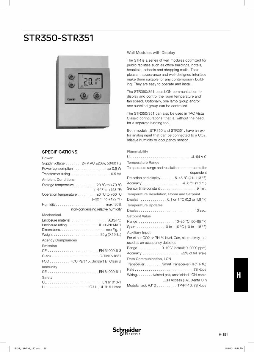
H-151
H
STR350-STR351
SPECIFICATIONSPower
Supply voltage . . . . . . . . 24 V AC ±20%, 50/60 Hz
Power consumption . . . . . . . . . . . . . . . .max 0.5 W
Transformer sizing . . . . . . . . . . . . . . . . . . . . 0.5 VA
Ambient Conditions
Storage temperature . . . . . . . . . . . –20 °C to +70 °C (–4 °F to +158 °F)
Operation temperature . . . . . . . . . .±0 °C to +50 °C (+32 °F to +122 °F)
Humidity . . . . . . . . . . . . . . . . . . . . . . . . . max. 90% non-condensing relative humidity
Mechanical
Enclosure material . . . . . . . . . . . . . . . . . . .ABS/PC Enclosure rating . . . . . . . . . . . . . . . . IP 20/NEMA 1 Dimensions . . . . . . . . . . . . . . . . . . . . . . . see Fig. 1 Weight . . . . . . . . . . . . . . . . . . . . . . . .85 g (0.19 lb.)
Agency Compliances
Emission CE . . . . . . . . . . . . . . . . . . . . . . . . . . EN 61000-6-3
C-tick . . . . . . . . . . . . . . . . . . . . . . . . C-Tick N1831
FCC . . . . . . . . . . FCC Part 15, Subpart B, Class B
Immunity CE . . . . . . . . . . . . . . . . . . . . . . . . . . EN 61000-6-1
Safety CE . . . . . . . . . . . . . . . . . . . . . . . . . . . EN 61010-1 UL . . . . . . . . . . . . . . . . . . . . . C-UL, UL 916 Listed
Wall Modules with Display
The STR is a series of wall modules optimized for public facilities such as office buildings, hotels, hospitals, schools and shopping malls. Their pleasant appearance and well-designed interface make them suitable for any contemporary build-ing. They are easy to operate and install.
The STR350/351 uses LON communication to display and control the room temperature and fan speed. Optionally, one lamp group and/or one sunblind group can be controlled.
The STR350/351 can also be used in TAC Vista Classic configurations, that is, without the need for a separate binding tool.
Both models, STR350 and STR351, have an ex-tra analog input that can be connected to a CO2, relative humidity or occupancy sensor.
Flammability
UL . . . . . . . . . . . . . . . . . . . . . . . . . . . . . UL 94 V-0
Temperature Range
Temperature range and resolution . . . . . . . controller dependent
Detection and display . . . . . . . 5–45 °C (41–113 °F)
Accuracy . . . . . . . . . . . . . . . . . . . . ±0.6 °C (1.1 °F)
Sensor time constant . . . . . . . . . . . . . . . . . . 9 min.
Temperature Resolution, Room and Setpoint
Display . . . . . . . . . . . . . 0.1 or 1 °C (0.2 or 1.8 °F)
Temperature Updates
Display . . . . . . . . . . . . . . . . . . . . . . . . . . . . 10 sec.
Setpoint Value
Range . . . . . . . . . . . . . . . . . . 10–35 °C (50–95 °F)
Span . . . . . . . . . . . . . .±0 to ±10 °C (±0 to ±18 °F)
Auxiliary Input
For either CO2 or RH-% level. Can, alternatively, be used as an occupancy detector.
Range . . . . . . . . . . . 0–10 V (default 0–2000 ppm)
Accuracy . . . . . . . . . . . . . . . . . . . ±2% of full scale
Data Communication, LON
Transceiver . . . . . . . . .Smart Transceiver (TP/FT-10)
Rate . . . . . . . . . . . . . . . . . . . . . . . . . . . . . .78 kbps
Wiring . . . . . . . . twisted pair, unshielded LON-cable
LON Access (TAC Xenta OP)
Modular jack RJ10 . . . . . . . . . . .TP/FT-10, 78 kbps
15434_131-236_150.indd 15115434_131-236_150.indd 151 11/1/13 4:51 PM11/1/13 4:51 PM

H-152
H
FUNCTIONS
Increase Button
The increase button is used to increase the tem-perature setpoint.
The Increase button is used to increase or turn on the selected value or function.
Decrease Button
The decrease button is used to decrease the temperature setpoint.
The Decrease button is used to decrease or turn off the selected value or function.
If the room temperature is being displayed when a button is pushed for the first time, the current effective setpoint will be displayed. A second push will change the value.
Select Button
The Select button is used to step through the menu.
The Select button is used to toggle between all configured functions. If a value is associated with the function it will appear on the display.
Bypass/On-Off Button
The bypass button is used to change from standby (economy) or unoccupied mode to comfort mode. When entering comfort mode, the symbol on the display shows a steady light. When the bypass time expires, the symbol returns to its previous status again, provided that the feedback mode is connected. Otherwise the symbol returns to the Off status after two hours.
If configured for On-Off function, pressing the button will toggle between the On/Comfort and Off/Economy modes for the HVAC functions, as well as for the light function.
Adjusting the Room Temperature
Use the Select button to step through the menu until the Increase and Decrease arrows are displayed. In this mode, change the temperature setpoint using the Increase/Decrease buttons.
Monitoring the Temperature
Use the Select button to step through the menu until the symbols for indoor or outdoor tempera-ture are displayed.
Adjusting the Fan Speed
Use the Select button to step through the menu until the fan symbol is displayed. If the fan is controllable, use the Increase/Decrease buttons.
System Options
The STR350/351 may be used in two kinds of systems
Both types of communication can be used in the same STR350/351 device.
The following functions are available:
Function SNVT Based
Vista Classic
Basic HVAC X X
CO2/RH/Occupancy X X
Sun blind X —
Light control X —
DIMENSIONS mm (in)
58 (2
.28)
116
(4.6
) 24
(0.9
)
84 (3.3)
82 (3.2)
LonMark Standard
Interoperability . .LonMark Interop. Guidelines v. 3.3
LonMark Functional Profiles
Space Comfort Control Command Module: #8090
Switch: #3200
Non-SNVT support in Xenta . . . . . v. 3.61 or higher
Part Number
STR350: Sensor temp room . . . . . . . . . 004605000
STR351: Sen. temp room w. backlight . 004605100
15434_131-236_150.indd 15215434_131-236_150.indd 152 11/1/13 4:51 PM11/1/13 4:51 PM

H-153
H
Application Options
Configuration is made with the Plug-in or with TAC Vista/Menta, which makes it easy to select different options with regard to the application. Some examples:
display.
temperature or the setpoint as the default value on the display.
If the room temperature is displayed by default, the Increase/Decrease buttons will switch the display to the setpoint value, while a time-out will restore the room temperature display.
temperature resolution.
value.
control.
occupancy detection.
Wiring
operation (LON and power supply). When the auxiliary input is used another two-wire
Cables
Twisted pair, unshielded. Min. cross-sectional area: 0.25 mm² (AWG-24). Max. distance: 30 m (100 ft).
Mounting
The units can be mounted directly onto the wall or fitted onto a wide variety of back-boxes. The
Maintenance
If necessary, the wall module may be cleaned with a soft cloth.
STR350-STR351
1. Increase button.2. Decrease button.3. Select button.4. Bypass button.
Figure 2
15434_131-236_150.indd 15315434_131-236_150.indd 153 11/1/13 4:51 PM11/1/13 4:51 PM

H-154
H
LONMARKS OBJECTS AND NETWORK VARIABLES
Fig 2: Node object
Fig 3: Switch object (SW#1 and SW#2)
Note! Only in SNVT-based systems!
15434_131-236_150.indd 15415434_131-236_150.indd 154 11/1/13 4:51 PM11/1/13 4:51 PM

H-155
H
LONMARKS OBJECTS AND NETWORK VARIABLES
Fig 4: Space comfort command module object
Note! Only in SNVT-based systems!
15434_131-236_150.indd 15515434_131-236_150.indd 155 11/1/13 4:51 PM11/1/13 4:51 PM

H-156
H
15434_131-236_150.indd 15615434_131-236_150.indd 156 11/1/13 4:51 PM11/1/13 4:51 PM

I-157
ISTR300
The STR is an electronic room transmitter that converts a measured temperature into an electric current signal. The transmitter is delivered as a complete unit, comprising a sensing element and an amplifier mounted in a housing.
STR300 is intended either for surface mounting on a wall or installation in a standard switch box in dry, dust-free rooms.
SPECIFICATIONSAmbient ConditionsStorage . . . . . . . . . . . . . . . . . . . . . . . -30 to +70°COperation . . . . . . . . . . . . . . . . . . . . . . . . 0 to 40°CHumidity . . . . . . . . . . . . . . . . . . . . . . . . . max 90%
non-condensing relative humidity
MechanicalMaterial (Housing) . . . . . . . . . . . . . . .ABS Plastic Enclosure Rating . . . . . . . . . . . . . . . . . . . . . . IP20Dimensions . . . . . . . . . . . . . . . . . . . . . . .see Fig 1
Agency CompliancesStandards . . . . . . . . . . . . . . . . . . . . . DIN IED751
EmissionCE . . . . . . . . . . . . . . . . . . . . . . . . . . EN61000-6-3
ImmunityCE . . . . . . . . . . . . . . . . . . . . . . . . . . EN 61000-6-1
SafetyCE . . . . . . . . . . . . . . . . . . . . . . . . . . . EN 61010-1
FlammabilityUL . . . . . . . . . . . . . . . . . . . . . . . . . . . . . UL 94 V-0
Temperature RangeRange . . . . . . . . . . . . . . . . . . . . . . . . . 0 to +40°COutput . . . . . . . . . . . . . . . . . . . . . . . . . . 4 to 20mASensing Element . . . . . . . . . . . . . Pt100, class BConnection . . . . . . . . . . . . . . . 2 wire current loopPower Supply . . . . . . . . . . . . . . . . . . 15 to 30VdcAccuracy . . . . . . . . . . . . . . . . . . . . . . . . +/- 0.5°K
(@ ambient temp. of 25°C and Ug – 24Vdc)Maximum Load . . . . . . . . . . . . R = (Um-15)/0.02ALinearity Error . . . . . . . . . . . . . . . . . . . . . +/- 0.5%
DIMENSIONS
Fig 1
ORDERING INFORMATION
Item No. Item
Reference
Description
006922000 STR300 STR300 Room
Temperature Transmitter
Room Temperature Transmitter
15434_131-236_150.indd 15715434_131-236_150.indd 157 11/1/13 4:51 PM11/1/13 4:51 PM

I-158
I
The transmitter is connected by a 2-wire cable, which serves both as power supply and signal transmission. Reading the measured signal value is achieved by having an external load resistance RL.
The supply voltage UM is the total of the voltage at the room transmitter UG and the voltage drop across the load resistor and the resistance of the wire.
WIRING
Fig 2
15434_131-236_150.indd 15815434_131-236_150.indd 158 11/1/13 4:51 PM11/1/13 4:51 PM

I-159
ISTC300
Pipe Contact Temperature Transmitter 4-20 mA
STC300 is an electronic pipe contact temperature transmitter that converts the temperature measured into an electronic current signal 4-20 mA.
The transmitter is delivered as a complete unit, comprising a pipe clamp, the sensing element and an amplifier, mounted in a housing. The sensor and amplifier are encapsulated in separate units, to protect the electronics from excessive heat. A 2 m cable connects the two units.
The transmitter is intended for external mounting directly on pipes, (max. dimension 100 mm) e.g. flow and return hot water pipes.
The transmitter is connected with a 2-wire cable, which serves both as a power supply and for signal transmission.
The reading of the measured signal is done over and external load resistance.
PART NUMBER
Part Number Model Number Range Weight
C F g lb.
006920021 STC300 -50/50 -50/50 -58/122 100 0.22
006920041 STC300 0/100 0/100 32/212 100 0.22
006920061 STC300 0/160 0/160 32/320 100 0.22
SPECIFICATIONS
Range . . . . . . . . . . . . . . . . . . . . . . . . . . . see table
Signal output . . . . . . . . . . . . . . . . . . . . . . 4-20 mA
Time constant . . . . . . . . . . . . . . . . . . approx. 75 s
Material
Clamp . . . . . . . . . . . . . . . . . . . . . . . . . . . . . . steel
Cable . . . . . . . . . . . . . . . . . . . . . . . . . . . . . Silicone
Connection box . . . . . . . . . . . . . .polyamide plastic
Enclosure rating . . . . . . . . . . . . . . . . . . . . . . . IP 65
Dimensions (in mm) . . according to figure and table
Voltage across transmitter . . . . . .UG max. 36 V DC
. . . . . . . . . . . . . . . . . . . . . . . . . . . UG min. 15 V DC
Maximum load (ohm) . . . . . . . . . R = (UM-9)/0,02 A
Voltage dependence . . . . . . . . 0,1°C (0.18°F) when UG = 15 to 36 V DC
Accuracy . . . . . . . . . . . . . . . . . . . 0,4 % of range R at ambient temp of 25 C (77 F) and U = 24 V DC)
Temperature dependence . . . . . . . . . . . . . 0,04 C/C at ambient temp. of 25 C (77 F) and U = 24 V DC
EMC . . . . . . . . . . . . . . . . EN50081-1, EN 50082-1
Voltage dependence . . . . . . . . .0,1 C (0.18 F) when UG = 15 to 36 V DC
Load dependence . . . . . . . . . 0,1°C (0.18°F) when R = 0 to max. R
Ambient Temperature (amplifier) . min -20° C (-4° F)
max. 70 C (158 F)
Standards
EMC . . . . . . . . . . . . . . . . EN 50081-1, EN 50082-1
Dimensions . . . . . . . . . . . . . . . . . . . . . . See page 2
15434_131-236_150.indd 15915434_131-236_150.indd 159 11/1/13 4:51 PM11/1/13 4:51 PM

I-160
I
DIMENSIONS mm (in)
WIRING
Ø15 (0.59)3 (0.11)
22 (0.86)
20 (0.78)
Ø 6 (0.23)10 (0.39)
32 (1.25)2000 (78.74)
11
R15
max Ø 100 (4)
1 2 3 4 5 6
1 2 3 4 5 6
PT100
2
3
4...20mA
UG
UG=15...36VDC
nc Loop
1 2 3 4 5 6
nc Loop
Wiring and Adjustment
The transmitter is factory calibrated for the required range within the specified accuracy, prior to delivery. Any further calibration should normally not be necessary. The sensor and the electronic unit are controlled together. If either of these are replaced, the transmitter is no longer in calibration.
The built in amplifier is equipped with two trim potentiometers:
ZERO to adjust the lower end of the range, 4 mA.
SPAN to adjust the upper end of the range, 20 mA.
When calibrating, adjust ZERO first and then SPAN. Because of a certain degree of interaction, the adjustment process must be repeated several times.
15434_131-236_150.indd 16015434_131-236_150.indd 160 11/1/13 4:51 PM11/1/13 4:51 PM

I-161
ISTD300
PART NUMBERS
SPECIFICATIONSRange . . . . . . . . . . . . . . . . . . . . . . . . . . . see tableSignal output . . . . . . . . . . . . . . . . . . . . . . 4-20 mAEnclosure rating . . . . . . . . . . . . . . . . . . . . . . IP 65Dimensions . . . . . . . . . . . . . . see figure and tableVoltage across transmitter . . . . . UG max. 36 V DC
UG min. 15 V DCMaximum load (ohm) . . . . . . . R = (UM – 9)/0.02AAccuracy . . . . . . . . . . . . . . . . . . . ±0.4 % of rangeat ambient temp. 25 °C (77 °F) and UG = 24 V DC
Temperature dependence. . . . . . . . . .±0.04 °C/°Cat ambient temp. 25 °C (77 °F) and UG = 24 V DC
Voltage dependence . . . . . . . . . . 0.1 °C (0.18 °F) when UG = 15 to 36 V DC
Load dependence . . . . . . . . . . . . . .0.1 °C (0.18 °F) when R = 0 to max. R
Ambient temp. (amplifier) . . . . . min. -20 °C (-4 °F)max. +70 °C (158 °F)
Time constantsAir velocity 1.5 m/s . . . . . . . . . . . . . . approx. 72 sAir velocity 3.0 m/s . . . . . . . . . . . . . . approx. 52 s
Materials
Immersion tube . . . . . . . . . . . . . . . . stainless steelConnection box . . . . . . . . . . . . . . polyamid plasticMounting flange . . . . . . . . . . . . . . . . black plastic
StandardsEMC . . . . . . . . . . . . . . . . EN 50081-1, EN 50082-1
Duct Temperature Transmitter
STD300 is an electronic temperature transmitter that converts the temperature measured into an electric current signal 4–20 mA.Two different temperature ranges are available.The transmitter is delivered as a complete unit, comprising a stainless steel immersion probe, the sensing element and an amplifier, mounted in a housing. The transmitter is intended for immersion installation and is used for temperature measure-ment in air ducts. A plastic duct mounting bracket is supplied, with a securing screw. The reading of the measured signal is done over an external load resistance RL.
Part Number Description Range NL Weight
006920130 STD300-300 -50/50 -50 °C to 50 °C (-58 °F to 122 °F) 313 (12.32) 125g (0.76)
006920150 STD300-300 0/100 0 °C to 100 °C (32 °F to 212 °F) 313 (12.32) 125g (0.76)
15434_131-236_150.indd 16115434_131-236_150.indd 161 11/1/13 4:51 PM11/1/13 4:51 PM

I-162
IDIMENSIONS (mm/in)
M20x1.5
64x84(2.52x3.31)
6.0(0.24)
54(2.13)
87(3
.43)
60(2
.36)
45(1
.77)
NL
1 2 3 4 5 6
nc Loop
Loopnc
UG=15...36 V DC
2
3
UG
PT100
4...20mA
Loopnc
1 2 3 4 5 6
WIRING & ADJUSTMENT The transmitter is factory calibrated for the required range within the specified accuracy, prior to delivery. Any further calibration should normally not be necessary. The sensor and the electronic unit are calibrated together. If either of these are replaced, the transmitter is no longer in calibration.
The built in amplifier is equipped with two trim potentiometers:
4 mA.
20 mA.
-
several times.
15434_131-236_150.indd 16215434_131-236_150.indd 162 11/1/13 4:51 PM11/1/13 4:51 PM

I-163
ISTP300
SPECIFICATIONS
Range . . . . . . . . . . . . . . . . . . . . . . . . . . . see table
Signal output . . . . . . . . . . . . . . . . . . . . . . 4-20 mA
Time constant without pocket in water .approx. 7 s
Time constant with pocket in water
Brass PN16 with Contact past . . . . . . . . . . . . .19 s
Brass PN16 without Contact past. . . . . . . . . . .23 s Stainless steel PN25 with Contact past . . . . . .20 s
Stainless steel PN25 without Contact past . . . .24 s
Materials
Immersion tube . . . . . . . . . . . . . . . . stainless steel
Connection box . . . . . . . . . . . . . . .polyamid plastic
Enclosure rating . . . . . . . . . . . . . . . . . . . . . . . IP 65
Dimensions (in mm) . . according to figure and table
Voltage across transmitter . . . . . .UG max. 36 V DC
UG min. 15 V DC
Maximum load (ohm) . . . . . . . . R = (UM – 9)/0,02A
Accuracy . . . . . . . . . . . . . . . . . . . .±0,4 % of range
at ambient temp. of 25 °C (77°F) and UG = 24 V DC
Temperature dependence . . . . . . . . . ±0,04 °C/°C
at ambient temp. of 25 °C (77°F) and UG = 24 V DC
Voltage dependence . . . . . . . 0,1 °C (0.18°F) when
UG = 15 to 36 V DC
Load dependence . . . . . . . . . . . . . . 0,1 °C(0.18°F) when R = 0 to max. R
Ambient temperature (amplifier) . min. -20°C (-4°F)
max. +70°C (158°F)
Standards
EMC . . . . . . . . . . . . . . . EN 50081-1, EN 50082-1
Immersion Pipe Temperature Sensor 4-20 mA
STP300 is an electronic immersion temperature transmitter that converts a measured tempera-ture into an electric current signal 4 – 20 mA.
STP300 is designed for immersion mounting in pipe systems with a separate pocket (well). The pocket is closed in the bottom, making it easy to replace the sensor, if necessary.
For a new installation the pocket has to be ordered separately, see Accessories.
The transmitter is intended for measurement of high and low temperatures.
The transmitter is connected with a 2-wire cable, which serves both as power supply and for signal transmission. The reading of the measured signal is done over an external load resistance RL. The supply voltage UM is the total of the voltage over the transmitter UG and the voltage drop across the load resistor and the wire resistances..
DIMENSIONS mm (in)
15434_131-236_150.indd 16315434_131-236_150.indd 163 11/1/13 4:51 PM11/1/13 4:51 PM

I-164
I
APPLIATION RECOMMENDATIONAPPLICATION RECOMMENDATION
If the media temperature is higher then 50 °C (122 °F) it is recommended to use a STP300 transmitter with a length 50–100 mm (2–4 in) longer then the pocket.
This minimise the risk to have to high ambient temperature for the amplifier. See figure.
WIRING
The transmitter will operate even if the cable connections at 2 and 3 are reversed.
Cable: 0,2-1,5 mm².
Note! Avoid contact with the sensor terminals if the connection wires are live.
WIRING
Part number Description Range NL Weight
˚C ˚F mm In. g lb
0-069-2022-0 STP300-100 -50/50 -50/50 -58/122 113 4.45 107 0.24
0-069-2024-0 STP300-100 0/100 0/100 32/212 113 4.45 107 0.24
0-069-2026-0 STP300-100 0/160 0/160 32/320 113 4.45 107 0.24
0-069-2028-0 STP300-200 -50/50 -50/50 -58/122 213 8.39 114 0.25
0-069-2030-0 STP300-200 0/100 0/100 32/212 213 8.39 114 0.25
0-069-2032-0 STP300-200 0/160 0/160 32/320 213 8.39 114 0.25
0-069-2034-0 STP300-300 -50/50 -50/50 -58/122 313 12.32 122 0.27
0-069-2036-0 STP300-300 0/100 0/100 32/212 313 12.32. 122 0.27
0-069-2038-0 STP300-300 0/160 0/160 32/320 313 12.32 122 0.27
0-069-2040-0 STP300-400 -50/50 -50/50 -58/122 413 16.26. 130 0.29
0-069-2042-0 STP300-400 0/100 0/100 32/212 413 16.26 130 0.29
0-069-2044-0 STP300-400 0/160 0/160 32/320 413 16.26 130 0.29
Amplifier
+ UM
Signal
0 V
UG
2
3
RI RL
RI
R = 2RI + RL
15434_131-236_150.indd 16415434_131-236_150.indd 164 11/1/13 4:51 PM11/1/13 4:51 PM

I-165
I
1 2 3 4 5 6
nc Loop
Loopnc
UG=15...36 V DC
2
3
UG
PT100
4...20mA
Loopnc
1 2 3 4 5 6
ADJUSTMENTADJUSTMENT
The transmitter is factory calibrated for the required range within the specified accuracy, prior to delivery. Any further calibration should normally not be necessary. The sensor and the electronic unit are calibrated together. If either of these are replaced, the transmitter is no longer in calibration.
The built in amplifier is equipped with two trim potentiometers:
• ZERO to adjust the lower end of the range, 4 mA.
• SPAN to adjust the upper end of the range, 20 mA.
When calibrating, adjust ZERO first and then SPAN. Because of a certain degree of interaction, the adjustment process must be repeated several times.
Part number Description Length (L) Weight
mm In. g lb
Brass NI plated pocket PN16
912-1040-000 Pocket STP 50 mm 63 2.48 85 0.19
912-1041-000 Pocket STP 100 mm 113 4.45 100 0.22
912-1042-000 Pocket STP 150 mm 163 6.42 115 0.25
912-1043-000 Pocket STP 200 mm 213 8.39 130 0.29
912-1044-000 Pocket STP 250 mm 263 10.35 145 0.32
912-1045-000 Pocket STP 300 mm 313 12.32 160 0.35
912-1046-000 Pocket STP 400 mm 413 16.26 190 0.42
Stainless steel pocket PN25
912-1050-000 Pocket STP 50 mm 63 2.48 75 0.17
912-1051-000 Pocket STP 100 mm 113 4.45 85 0.19
912-1052-000 Pocket STP 150 mm 163 6.42 95 0.21
912-1053-000 Pocket STP 200 mm 213 8.39 105 0.23
912-1054-000 Pocket STP 250 mm 263 10.35 115 0.25
912-1055-000 Pocket STP 300 mm 313 12.32 125 0.28
912-1056-000 Pocket STP 400 mm 413 16.26 145 0.32
ACCESSORIES
15434_131-236_150.indd 16515434_131-236_150.indd 165 11/1/13 4:51 PM11/1/13 4:51 PM

I-166
I
14
R1/2E
L
L
SW22
10
10x7
Ø194,
213
DIMENSIONS mm (in)
14
G1/2
EL
L
SW27
8
10x7
13
M4
Brass NI plated pocket PN16 Stainless steel pocket PN25
15434_131-236_150.indd 16615434_131-236_150.indd 166 11/1/13 4:51 PM11/1/13 4:51 PM

I-167
IST0300
SPECIFICATIONS
Outdoor Temperature Sensor
STO300 is an electronic temperature transmitter that converts the measurement into an electric signal 4–20 mA.
The transmitter is supplied as a complete unit, comprising the sensing element, the ampli-fier mounted in a housing, which is resistant to ultraviolet light.
The transmitter is intended for mounting on an outside wall, on the north side where possible.
The transmitter is connected over a 2-wire cable, which serves both as power supply and signal transmission.
The reading of the measured signal is done over an external load resistance RL. The supply volt-age UM is the total of the voltage at the outdoor transmitter UG and the voltage drop across the load resistor and the wire resistances.
DIMENSIONS mm (in)
Fig 1
Range . . . . . . . . . . . . . . . . . . . . . . . . . . See Table
Signal Output . . . . . . . . . . . . . . . . . . . . . 4-20 mA
Time Constant . . . . . . . . . . . . . . . . approx. 2 min.
Materials
Immersion tube . . . . . . . . . . . . . . . Stainless Steel
Connection box . . . . . . . . . . . . . . polyamid plastic
Enclosure rating . . . . . . . . . . . . . . . . . . . . . . IP65
Dimensions (in mm) . . . . . . . see figure and table
Voltage across transmitter . . . . . .UG max. 36 Vdc
UG min. 15 Vdc
Maximum load (ohm) . . . . . . . . R+ (UM -9)/0,02A
Accuracy . . . . . . . . . . . . . . . . . . . .±0,4% of range
at ambient temp. of 25°C (77°F) and UG = 15 to 35 Vdc
Load Dependence . . . . . . . . . . . . 0,1°C (0.18°F) when R = 0 to max. R
Ambient temperature (amplifier)Minimum . . . . . . . . . . . . . . . . . . . . . .-30°C (-22°F)
Maximum . . . . . . . . . . . . . . . . . . . . .+60°C (140°F)
Standards:
EMC . . . . . . . . . . . . . . . . EN 50081-1, EN 50082-1
15434_131-236_150.indd 16715434_131-236_150.indd 167 11/1/13 4:51 PM11/1/13 4:51 PM

I-168
I
PARTSPart Number Order Code °C °F g lb
ST0300-50/50 0-069-2050-0 -50/50 -58/122 100 0.22
ADJUSTMENTThe transmitter is factory calibrated for the required range within the specified accuracy prior to delivery. Any further calibration should normally not be necessary. The sensor and hte electronic unit are calibrated together. If either of these are replaced the transmitter is no longer in calibration.
The built in amplifier is equipped with two trim potentiometers:
ZERO to adjust the lower end of the range, 4 mA.SPAN to adjust the upper end of the range, 20 mA.
When calibrating, adjust ZERO first, and then SPAN. Due to a certain degree of interaction, the adjustment process must be repeated several times.
WIRING
The transmitter will operate even if the cable commections at 2 and 3 are reversed.
Cable: 0,2 - 1,5 mm2
Note! Avoid contact with the sensor terminals if the connection wires are live.
1 2 3 4 5 6
nc Loop
Loopnc
UG=15...36 V DC
2
3
UG
PT100
4...20mA
Loopnc
1 2 3 4 5 6
1 +
2 − 0 V
RI
RI RL
M+U
UG
R = 2 +RI RL
SignalAmplifier
Sensingelement
15434_131-236_150.indd 16815434_131-236_150.indd 168 11/1/13 4:51 PM11/1/13 4:51 PM
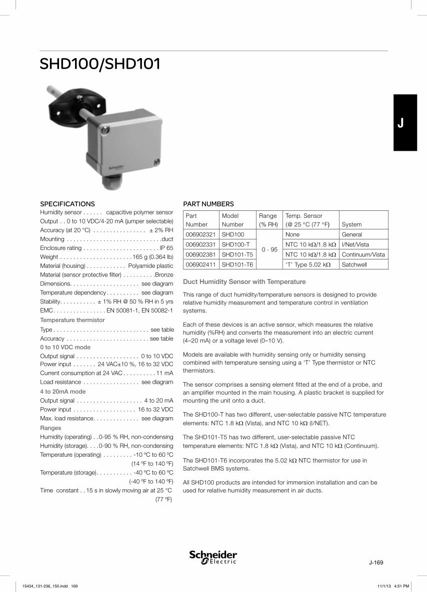
J-169
J
SHD100/SHD101
PART NUMBERS
Duct Humidity Sensor with Temperature
This range of duct humidity/temperature sensors is designed to provide relative humidity measurement and temperature control in ventilation systems.
Each of these devices is an active sensor, which measures the relative humidity (%RH) and converts the measurement into an electric current (4–20 mA) or a voltage level (0–10 V).
Models are available with humidity sensing only or humidity sensing combined with temperature sensing using a ‘T’ Type thermistor or NTC thermistors.
The sensor comprises a sensing element fitted at the end of a probe, and an amplifier mounted in the main housing. A plastic bracket is supplied for mounting the unit onto a duct.
The SHD100-T has two different, user-selectable passive NTC temperature elements: NTC 1.8 kΩ (Vista), and NTC 10 kΩ (I/NET).
The SHD101-T5 has two different, user-selectable passive NTC temperature elements: NTC 1.8 kΩ (Vista), and NTC 10 kΩ (Continuum).
The SHD101-T6 incorporates the 5.02 kΩ NTC thermistor for use in Satchwell BMS systems.
All SHD100 products are intended for immersion installation and can be used for relative humidity measurement in air ducts.
Part Number
Model Number
Range (% RH)
Temp. Sensor (@ 25 °C (77 °F) System
006902321 SHD100
0 - 95
None General
006902331 SHD100-T NTC 10 kΩ/1.8 kΩ I/Net/Vista
006902381 SHD101-T5 NTC 10 kΩ/1.8 kΩ Continuum/Vista
006902411 SHD101-T6 ‘T’ Type 5.02 kΩ Satchwell
SPECIFICATIONSHumidity sensor . . . . . . capacitive polymer sensor
Output . . 0 to 10 VDC/4-20 mA (jumper selectable)
Accuracy (at 20 °C) . . . . . . . . . . . . . . . . ± 2% RH
Mounting . . . . . . . . . . . . . . . . . . . . . . . . . . . . .duct
Enclosure rating . . . . . . . . . . . . . . . . . . . . . . . IP 65
Weight . . . . . . . . . . . . . . . . . . . . . . 165 g (0.364 lb)
Material (housing) . . . . . . . . . . . . Polyamide plastic
Material (sensor protective filter) . . . . . . . . . .Bronze
Dimensions . . . . . . . . . . . . . . . . . . . . . see diagram
Temperature dependency . . . . . . . . . . see diagram
Stability . . . . . . . . . . . ± 1% RH @ 50 % RH in 5 yrs
EMC . . . . . . . . . . . . . . . . EN 50081-1, EN 50082-1
Temperature thermistor
Type . . . . . . . . . . . . . . . . . . . . . . . . . . . . . see table
Accuracy . . . . . . . . . . . . . . . . . . . . . . . . . see table 0 to 10 VDC mode
Output signal . . . . . . . . . . . . . . . . . . . 0 to 10 VDC Power input . . . . . . . 24 VAC±10 %, 16 to 32 VDC
Current consumption at 24 VAC . . . . . . . . . . 11 mA
Load resistance . . . . . . . . . . . . . . . . . see diagram
4 to 20mA mode
Output signal . . . . . . . . . . . . . . . . . . . . 4 to 20 mA
Power input . . . . . . . . . . . . . . . . . . . 16 to 32 VDC
Max. load resistance . . . . . . . . . . . . . . see diagram
Ranges
Humidity (operating) . .0-95 % RH, non-condensing
Humidity (storage) . . . .0-90 % RH, non-condensing
Temperature (operating) . . . . . . . . . -10 ºC to 60 ºC
(14 ºF to 140 ºF)
Temperature (storage) . . . . . . . . . . . -40 ºC to 60 ºC
(-40 ºF to 140 ºF)
Time constant . . 15 s in slowly moving air at 25 °C
(77 ºF)
15434_131-236_150.indd 16915434_131-236_150.indd 169 11/1/13 4:51 PM11/1/13 4:51 PM

J-170
J M20x1.5
64x84(2.52x3.31)
12(0.47)
59(2.32)
87(3
.43)
60(2
.36)
45(1
.77)
230
(9.0
6)
TEMPERATURE DEPENDENCE
0.3
0.2
0.1
0
-0.1
-0.2
-0.3T/°C (°F)
%/rorrE
-10 (14) 0 (32) 10 (50) 20 (68) 30 (86) 40 (104) 50 (122) 60 (140)
DIMENSIONS mm (in) THERMISTOR ACCURACYNTC 1.8 kΩ for Vista Products
–25 °C (–13 °F) . . . . . . . . . . . . . ±0.7 °C (±1.3 °F)
0 °C (32 °F) . . . . . . . . . . . . . . . . ±0.5 °C (±0.9 °F)
25 °C (77 °F) . . . . . . . . . . . . . . . ±0.3 °C (±0.5 °F)
50 °C (122 °F) . . . . . . . . . . . . . . ±0.6 °C (±1.1 °F)
75 °C (167 °F) . . . . . . . . . . . . . . ±0.9 °C (±1.6 °F)
100 °C (212 °F) . . . . . . . . . . . . . ±1.3 °C (±2.3 °F)
NTC 10 kΩ for I/NET® Products
–25 °C (–13 °F) . . . . . . . . . . . . . ±0.5 °C (±0.9 °F)
0 °C (32 °F) . . . . . . . . . . . . . . . . ±0.2 °C (±0.4 °F)
25 °C (77 °F) . . . . . . . . . . . . . . . ±0.2 °C (±0.4 °F)
50 °C (122 °F) . . . . . . . . . . . . . . ±0.2 °C (±0.4 °F)
70 °C (158 °F) . . . . . . . . . . . . . . ±0.2 °C (±0.4 °F)
100 °C (212 °F) . . . . . . . . . . . . . ±0.5 °C (±0.9 °F)
NTC 10 kΩ for Continuum® Products
–25 °C (–13 °F) . . . . . . . . . . . . . ±0.5 °C (±0.9 °F)
0 °C (32 °F) . . . . . . . . . . . . . . . . ±0.2 °C (±0.4 °F)
25 °C (77 °F) . . . . . . . . . . . . . . . ±0.2 °C (±0.4 °F)
50 °C (122 °F) . . . . . . . . . . . . . . ±0.2 °C (±0.4 °F)
70 °C (158 °F) . . . . . . . . . . . . . . ±0.2 °C (±0.4 °F)
100 °C (212 °F) . . . . . . . . . . . . . ±0.5 °C (±0.9 °F)
NTC 5.02 kΩ for Satchwell™ Products
–25 °C (–13 °F) . . . . . . . . . . . . . ±0.6 °C (±1.0 °F)
0 °C (32 °F) . . . . . . . . . . . . . . . . ±0.3 °C (±0.5 °F)
25 °C (77 °F) . . . . . . . . . . . . . . . ±0.2 °C (±0.4 °F)
50 °C (122 °F) . . . . . . . . . . . . . . ±0.2 °C (±0.4 °F)
75 °C (167 °F) . . . . . . . . . . . . . . ±0.3 °C (±0.5 °F)
100 °C (212 °F) . . . . . . . . . . . . . ±0.3 °C (±0.5 °F)
15434_131-236_150.indd 17015434_131-236_150.indd 170 11/1/13 4:51 PM11/1/13 4:51 PM

J-171
J1 +
2 − 0 V
RI
RI RL
M+U
UG
R = 2 +RI RL
SignalAmplifier
Sensingelement
Note: Maximum R = (UM -16V)/0.02A
Power supply16 - 32 VDC
Set jumper to
4 - 20 mA
mode
If another load is to be connected close to the sensor, this should be made with a separate G0, so that the measuring signal will not be affected.
0 –10 V
1
4
2
3
0 V
VRL
S+U
SignalAmplifier
Sensingelement
Power supply16 - 32 VDC24 VAC ±10 % RL = > 20 k
Set jumper to
0 - 10 V mode
WIRING
4-20 mA
Current is proportional to the measured humidity and is measured over an external load resistance RL. The supply voltage UM is a function of the voltage across the sensor UG and the voltage drop across the load resistor and the wire resistances RI.
UG Max. = 32 VDC, UG Min = 16 VDC. At 36 VDC accuracy drops by approximately 1 % RH.
Notes: Do not touch the sensor tip. Ensure correct wiring.
Temperature thermistor
5 6 7
1.8 k 5.02 k
SHD100-T/101-T6)
10 k Not SHD101-T6
15434_131-236_150.indd 17115434_131-236_150.indd 171 11/1/13 4:51 PM11/1/13 4:51 PM

J-172
J
15434_131-236_150.indd 17215434_131-236_150.indd 172 11/1/13 4:51 PM11/1/13 4:51 PM
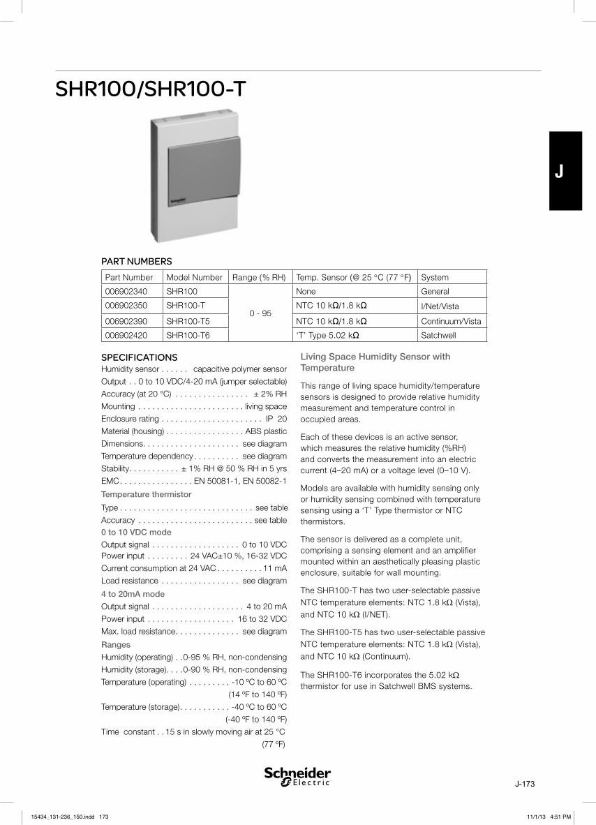
J-173
J
SHR100/SHR100-T
Living Space Humidity Sensor with Temperature
This range of living space humidity/temperature sensors is designed to provide relative humidity measurement and temperature control in occupied areas.
Each of these devices is an active sensor, which measures the relative humidity (%RH) and converts the measurement into an electric current (4–20 mA) or a voltage level (0–10 V).
Models are available with humidity sensing only or humidity sensing combined with temperature sensing using a ‘T’ Type thermistor or NTC thermistors.
The sensor is delivered as a complete unit, comprising a sensing element and an amplifier mounted within an aesthetically pleasing plastic enclosure, suitable for wall mounting.
The SHR100-T has two user-selectable passive NTC temperature elements: NTC 1.8 kΩ (Vista), and NTC 10 kΩ (I/NET).
The SHR100-T5 has two user-selectable passive NTC temperature elements: NTC 1.8 kΩ (Vista), and NTC 10 kΩ (Continuum).
The SHR100-T6 incorporates the 5.02 kΩ thermistor for use in Satchwell BMS systems.
SPECIFICATIONSHumidity sensor . . . . . . capacitive polymer sensor
Output . . 0 to 10 VDC/4-20 mA (jumper selectable)
Accuracy (at 20 °C) . . . . . . . . . . . . . . . . ± 2% RH
Mounting . . . . . . . . . . . . . . . . . . . . . . . living space
Enclosure rating . . . . . . . . . . . . . . . . . . . . . . IP 20
Material (housing) . . . . . . . . . . . . . . . . . ABS plastic
Dimensions . . . . . . . . . . . . . . . . . . . . . see diagram
Temperature dependency . . . . . . . . . . see diagram
Stability . . . . . . . . . . . ± 1% RH @ 50 % RH in 5 yrs
EMC . . . . . . . . . . . . . . . . EN 50081-1, EN 50082-1
Temperature thermistor
Type . . . . . . . . . . . . . . . . . . . . . . . . . . . . . see table
Accuracy . . . . . . . . . . . . . . . . . . . . . . . . . see table 0 to 10 VDC mode
Output signal . . . . . . . . . . . . . . . . . . . 0 to 10 VDC Power input . . . . . . . . . 24 VAC±10 %, 16-32 VDC
Current consumption at 24 VAC . . . . . . . . . . 11 mA
Load resistance . . . . . . . . . . . . . . . . . see diagram
4 to 20mA mode
Output signal . . . . . . . . . . . . . . . . . . . . 4 to 20 mA
Power input . . . . . . . . . . . . . . . . . . . 16 to 32 VDC
Max. load resistance . . . . . . . . . . . . . . see diagram
Ranges
Humidity (operating) . .0-95 % RH, non-condensing
Humidity (storage) . . . .0-90 % RH, non-condensing
Temperature (operating) . . . . . . . . . -10 ºC to 60 ºC
(14 ºF to 140 ºF)
Temperature (storage) . . . . . . . . . . . -40 ºC to 60 ºC
(-40 ºF to 140 ºF)
Time constant . . 15 s in slowly moving air at 25 °C
(77 ºF)
PART NUMBERSPart Number Model Number Range (% RH) Temp. Sensor (@ 25 °C (77 °F) System
006902340 SHR100
0 - 95
None General
006902350 SHR100-T NTC 10 kΩ/1.8 kΩ I/Net/Vista
006902390 SHR100-T5 NTC 10 kΩ/1.8 kΩ Continuum/Vista
006902420 SHR100-T6 ‘T’ Type 5.02 kΩ Satchwell
15434_131-236_150.indd 17315434_131-236_150.indd 173 11/1/13 4:51 PM11/1/13 4:51 PM

J-174
J
DIMENSIONS mm (in)
11
6 (
4.5
7)
58
(2
.28
)
24
(0
.94
)84 (3.31)
82 (3.23)
TEMPERATURE DEPENDENCE
0.3
0.2
0.1
0
-0.1
-0.2
-0.3T/°C (°F)
%/rorrE
-10 (14) 0 (32) 10 (50) 20 (68) 30 (86) 40 (104) 50 (122) 60 (140)
THERMISTOR ACCURACYNTC 1.8 kΩ for Vista Products
–25 °C (–13 °F) . . . . . . . . . . . . . ±0.7 °C (±1.3 °F)
0 °C (32 °F) . . . . . . . . . . . . . . . . ±0.5 °C (±0.9 °F)
25 °C (77 °F) . . . . . . . . . . . . . . . ±0.3 °C (±0.5 °F)
50 °C (122 °F) . . . . . . . . . . . . . . ±0.6 °C (±1.1 °F)
75 °C (167 °F) . . . . . . . . . . . . . . ±0.9 °C (±1.6 °F)
100 °C (212 °F) . . . . . . . . . . . . . ±1.3 °C (±2.3 °F)
NTC 10 kΩ for I/NET® Products
–25 °C (–13 °F) . . . . . . . . . . . . . ±0.5 °C (±0.9 °F)
0 °C (32 °F) . . . . . . . . . . . . . . . . ±0.2 °C (±0.4 °F)
25 °C (77 °F) . . . . . . . . . . . . . . . ±0.2 °C (±0.4 °F)
50 °C (122 °F) . . . . . . . . . . . . . . ±0.2 °C (±0.4 °F)
70 °C (158 °F) . . . . . . . . . . . . . . ±0.2 °C (±0.4 °F)
100 °C (212 °F) . . . . . . . . . . . . . ±0.5 °C (±0.9 °F)
NTC 10 kΩ for Continuum® Products
–25 °C (–13 °F) . . . . . . . . . . . . . ±0.5 °C (±0.9 °F)
0 °C (32 °F) . . . . . . . . . . . . . . . . ±0.2 °C (±0.4 °F)
25 °C (77 °F) . . . . . . . . . . . . . . . ±0.2 °C (±0.4 °F)
50 °C (122 °F) . . . . . . . . . . . . . . ±0.2 °C (±0.4 °F)
70 °C (158 °F) . . . . . . . . . . . . . . ±0.2 °C (±0.4 °F)
100 °C (212 °F) . . . . . . . . . . . . . ±0.5 °C (±0.9 °F)
NTC 5.02 kΩ for Satchwell™ Products
–25 °C (–13 °F) . . . . . . . . . . . . . ±0.6 °C (±1.0 °F)
0 °C (32 °F) . . . . . . . . . . . . . . . . ±0.3 °C (±0.5 °F)
25 °C (77 °F) . . . . . . . . . . . . . . . ±0.2 °C (±0.4 °F)
50 °C (122 °F) . . . . . . . . . . . . . . ±0.2 °C (±0.4 °F)
75 °C (167 °F) . . . . . . . . . . . . . . ±0.3 °C (±0.5 °F)
100 °C (212 °F) . . . . . . . . . . . . . ±0.3 °C (±0.5 °F)
15434_131-236_150.indd 17415434_131-236_150.indd 174 11/1/13 4:51 PM11/1/13 4:51 PM

J-175
J
21
24
23
22
0 V
VRL
S+U
SignalAmplifier
Sensingelement
Power supply16 - 32 VDC24 VAC ±10 % RL = > 20 k
Set jumper to
0 - 10 V mode
24 23 22 21
24 +
23 − 0 V
RI
RI RL
M+U
UG
R = 2 +RI RL
SignalAmplifier
Sensingelement
Note: Maximum R = (UM -16V)/0.02A
Power supply16 - 32 VDC
Set jumper to
4 - 20 mA
mode
24 23 22 21
11 12 13
1.8 k 5.02 k
SHR100-T/T6)
10 k Not SHR100-T6
WIRING
4-20 mA
Current is proportional to the measured humidity and is measured over an external load resistance RL. The supply voltage UM is a function of the voltage across the sensor UG and the voltage drop across the load resistor and the wire resistances RI.
UG Max. = 32 VDC, UG Min = 16 VDC. At 36 VDC accuracy drops by approximately 1 % RH.
Note: Ensure correct wiring.
If another load is to be connected close to the sensor, this should be made with a separate G0, so that the measuring signal will not be affected.
0 –10 V
Temperature thermistor
15434_131-236_150.indd 17515434_131-236_150.indd 175 11/1/13 4:51 PM11/1/13 4:51 PM

J-176
J
15434_131-236_150.indd 17615434_131-236_150.indd 176 11/1/13 4:51 PM11/1/13 4:51 PM

J-177
J
SHO100/SHO101 (-T5)
SPECIFICATIONSPart numberSHO100 . . . . . . . . . . . . . . . . . . . . . . 0-069-0236-0
SHO100-T . . . . . . . . . . . . . . . . . . . . 0-069-0237-0
SHO101-T5 . . . . . . . . . . . . . . . . . . . 0-069-0240-0
Time constant . . . . . . . . . . . . . . . . . . . . . . . . <15 s (depending on air circulation)
Accuracy . . . . . . . . . . . . . . . . . . . . . . . . ± 2% RH
Temp.dep, -10 °C to 60 °C (fig pg 2) . < ±0.3% RH
(worst case, at 90%RH; D %RH will be less at lower %RH)
Max. inaccuracy after 5 years . . . . . . . . < ± 3% RH
Operating range . . . . . . . . . . . . . . . . . . .0–95% RH
Operating temperature . . . . . . . . . . -10 °C to 60 °C (14 to 140 °F)
Storage temperature . . . . . . . . . . . . -40 °C to 60 °C (–40 to 140 °F)
Only SHD100-T
Sensor element . . .NTC, 1.8 kohm at 25 °C (77 °F)
Sensor element . 1) NTC, 10 kohm at 25 °C (77 °F)
Only SHD101-T5
Sensor element . . .NTC, 1.8 kohm at 25 °C (77 °F)
Sensor element . 2) NTC, 10 kohm at 25 °C (77 °F)
Outdoor Humidity Transmitter 0-10 V/4-20 mA
SHO100 is an active sensor, which measures the relative humidity (RH) and converts the measure-ment into an electric current 4–20 mA or a volt-age level 0–10 V.
The transmitter is delivered as a complete unit, comprising a protective filter for the protruding sensor element, and an amplifier mounted in the housing.
SHO100-T is equipped with passive temperature elements selectable NTC 1.8 / 10 kohm. The NTC 10 kohm is for I/NET® products.
SHO101-T5 is equipped with passive tempera-ture elements selectable NTC 1.8 / 10 kohm. The NTC 10 kohm is for Continuum® products. SHO101-T5 has an M16/M20 adapter for con-duits.
SHO100 is intended for outdoor installation and for indoor areas where a more robust design is needed, as warehouse.
The sensor has negligeable hysteresis and it is insensitive to dust as well as most chemicals.
Materials
Housing . . . . . . . . . . . . . . . . . . . .polyamide plastic
Protective filter for sensor . . . . . . . . . . . . . .bronze
Enclosure rating . . . . . . . . . . . . . . . . . . . . . . . lP 65
Weight . . . . . . . . . . . . . . . . . . . . . . 130 g (0.287 lb)
Standards
EMC . . . . . . . . . . . . . . . EN 50081-1, EN 50082-1
4–20 mA
Current output 0–100% RH . . . . . . . . . . 4–20 mA
Voltage across sensor . . . . U G max. 28 (36) V DC,
U G min. 15 V DC
At a 36 V DC supply accuracy decr. with about 1 % RH.
Maximum load (ohm) . . . . . . . . .R = (U M –15)/0.02
0–10 V
Voltage output 0 –100% RH . . . . . . . . . . . . .0–10 V
Power supply
Output 0–10 V . . . . . . . . . . . . . . . . . . .15–35 V DC
alternatively 24±10% V AC
Current consumption, typical . . . . . . . . . . . . 10 mA
Load resistance . . . . . . . . . . . . . . . . . . . >20 kohm
15434_131-236_150.indd 17715434_131-236_150.indd 177 11/1/13 4:51 PM11/1/13 4:51 PM

J-178
J
0.3
0.2
0.1
0
-0.1
-0.2
-0.3T/°C
erro
r/% -10 0 10 20 30 40 50 60
TEMPERATURE DEPENDENCE
1 +
2 − 0 V
RI
RI RL
M+U
UG
R = 2 +RI RL
SignalAmplifier
Sensingelement
INSTALLATION
64(2
.52)
58x35(2.28x1.38)
M16x1,5
30(1
.18)
O 12.5(O 0.49)
DIMENSIONS mm (in)
INSTALLATION
Note! The wires must be connected in the correct way.
The sensor must not be touched, since it is sen-sitive to mechanical damage and to grease etc. from the fingers.
4–20 mAThe transmitter is connected with a 2-wire cable. The current is proportional to the measured humidity and it is measured over an external load resistance R L .
The supply voltage U M is a function of the volt-age across the room transmitter U G and the voltage drop across the load resistor and the wire resistances.
!
4-20 mA
SHO101-T5 has an M16x1.5 cable gland and an M16/M20 adapter.
15434_131-236_150.indd 17815434_131-236_150.indd 178 11/1/13 4:51 PM11/1/13 4:51 PM

J-179
J
1 +
2 − 0 V
RI
RI RL
M+U
UG
R = 2 +RI RL
SignalAmplifier
Sensingelement
INSTALLATION
NTC
321 654 7
YLoopG GO+ -
4...20mA / 0...10V 0...100%r.H.
321 654 7
YG NTC
1.8K
GO NTC
10K
MO
SHO100-T
Jumper
0...10V
4...20mA
full scale
zero point
+ -Loop
UG=15…36 VDC / 24 VAC ± 10%
321 654 7
YLoopG GO
nc
Jumper
UG=15…36 VDC / 24 VAC ± 10%
+ -
321 654 7
YG ncGO+ -
0...10V
4...20mA
full scale
zero point
SHO100
Loop
4...20mA / 0...10V 0...100%r.H.
SHO101-T5and
WIRING
0-10 V
0-10 V
0–10 V
The transmitter is connected with a 3-wire cable.
If another load is to be connected close to the sensor, this should be made with a separate Go, so that the measuring signal will not be affected.
15434_131-236_150.indd 17915434_131-236_150.indd 179 11/1/13 4:51 PM11/1/13 4:51 PM

J-180
J
ACCURACY
NTC 1.8 kohm
–25 °C/–13 °F . . . . . . . . . . . . . . . ±0.7 °C/±1.3 °F
±0 °C/32 °F . . . . . . . . . . . . . . . . . .±0.5 °C/±0.9 °F
25 °C/77 °F . . . . . . . . . . . . . . . . . .±0.3 °C/±0.5 °F
50 °C/122 °F . . . . . . . . . . . . . . . . ±0.6 °C/±1.1 °F
75 °C/167 °F . . . . . . . . . . . . . . . . .±0.9 °C/±1.6 °F
100 °C/212 °F . . . . . . . . . . . . . . . .±1.3 °C/±2.3 °F
NTC 10 kohm for I/NET® products
–25 °C/–13 °F . . . . . . . . . . . . . . . ±0.5 °C/±0.9 °F
±0 °C/32 °F . . . . . . . . . . . . . . . . . .±0.2 °C/±0.4 °F
25 °C/77 °F . . . . . . . . . . . . . . . . . ±0.2 °C/±0.4 °F
50 °C/122 °F . . . . . . . . . . . . . . . . ±0.2 °C/±0.4 °F
70 °C/158 °F . . . . . . . . . . . . . . . . .±0.2 °C/±0.4 °F
100 °C/212 °F . . . . . . . . . . . . . . . .±0.5 °C/±0.9 °F
NTC 10 kohm for Continuum® products
–25 °C/–13 °F . . . . . . . . . . . . . . . ±0.5 °C/±0.9 °F
±0 °C/32 °F . . . . . . . . . . . . . . . . . .±0.2 °C/±0.4 °F
25 °C/77 °F . . . . . . . . . . . . . . . . . ±0.2 °C/±0.4 °F
50 °C/122 °F . . . . . . . . . . . . . . . . ±0.2 °C/±0.4 °F
70 °C/158 °F . . . . . . . . . . . . . . . . .±0.2 °C/±0.4 °F
100 °C/212 °F . . . . . . . . . . . . . . . .±0.5 °C/±0.9 °F
15434_131-236_150.indd 18015434_131-236_150.indd 180 11/1/13 4:51 PM11/1/13 4:51 PM

K-181
K
SPD310/SPD360
Differential Pressure Transmitter Air 0-10 V
SPD310/SPD360 Differential pressure transmitters are used in air handling systems for the monitoring of air ducts, filters and fans.SPD310/SPD360 are electronic differential pressure transmitters that convert the measured differential pressure into an electric 0 - 10V signal. Four meas-uring ranges are user selectable (jumper/see table). For special applications the output signal can be configured symmetrically (jumper ”sym”).SPD360 has a LC display, showing the differential pressure in Pa or mbar (jumper “mbar”) or InH2O (jumper “InH2O”).SPD310/SPD360 are delivered with 2 metres of tube and two plastic duct connectors.Medium: air and non-aggressive gases.
PRODUCT SPECIFICATIONS
PART NUMBERPart Number Product
004700320 SPD310-100/300/500/1000 Pa
004700340 SPD310-1000/1200/2500/5000
Pa
004700360 SPD360-300/500/1000/2500 Pa
Signal Output . . . . . . . . . . . . . . . . . . . 0 - 10 VDCPower. . . . . . . . . . . . . 24 VAC ±10%/15 - 32 VDCLoad Resistance . . . . . . . . . . . . . . . . . >50 kOhmCurrent Consumtion . . . . . . . . . . . . . . . . . .10 mAAccuracy (linear output) . . . . . . . . . . . ≤0.75%FS0 - 100 Pa . . . . . . . . . . . . . . . . . . . . . . . ≤1.5%FSLinearity inc. temperature and hysteresis . . . . . . . . . . . . . . . . . . . . . . . . . ≤2%FS0 - 100 Pa. . . . . . . . . . . . . . . . . . . . . . . . . . ≤4%FSAccuracy at ambient temp. of 25 ˚C/UG - 24V . . . . . . . . . . . . . . . . ≤±0.4%FS
Ambient TemperatureOperation . . . . . . . . . . .-20 to 60 ˚C (-4 to 140 ˚F)Storage . . . . . . . . . . . .-30 to 85 ˚C (-22 to 185 ˚F)Load Change . . . . . . . . . . . . . . . . . . . . . . <10 HzResponse Time . . . . . . . . . . . . . . . . . . . . . <10 ms
Materials:Housing . . . . . . . . . . . . . . . . . . . . . . . . . . . . . . .PPDuct Connections . . . . . . . . . . . . . . . . . . . . . ABSTubing . . . . . . . . . . . . . . . . . . . . . . . . . . PVC, softEnclosure Rating . . . . . . . . . . . . . . . . . . . . . IP65Weight . . . . . . . . . . . . . . . . . . . . . . . . . . . . . 150 gEMC Standards . . . . .EN 50081-1, EN 50082-12
Max. Pressure100/300/500/1000 Pa . . . . . . . . . . . . . 10,000 Pa1000/1200/2500/5000 Pa . . . . . . . . . . 50,000 Pa
15434_131-236_150.indd 18115434_131-236_150.indd 181 11/1/13 4:51 PM11/1/13 4:51 PM

K-182
K
DIMENSIONS85
56
0130
1000 100Pa
5000
2500
1200 300Pa
500Pa
1000Pa
mbar
psi
sym.
1 2 3G0YG
321
Wiring details
15434_131-236_150.indd 18215434_131-236_150.indd 182 11/1/13 4:51 PM11/1/13 4:51 PM

K-183
K
SPD910 Differential Air Pressure Switch
This range of four SPD910 differential air flow switches are intended for use in air handling systems for the monitoring of air ducts, filters and fans.
The enclosure is plastic with a rating of IP54. A set-point adjustment is provided under the clip-on clear plastic cover.
The mounting bracket and tubing is supplied.
DESCRIPTIONSee part number table on page 2
Medium Air and neutral gasesPressure Range 0.2 … 50 mbarTolerable overload on one side 75 mbar at –30 … 75 °C
50 mbar at –30 … 85 °C
Repeatability 0.2 … 3 mbar ±0.025 mbar0.5 … 5 mbar ±0.05 mbar1 … 10 mbar ±0.05 mbar5 … 20 mbar ±0.05 mbar10 … 50 mbar ±0.15 mbar
Switching Load Resistive Load 5 A at 250 Vac4 A at 30 Vdc
Inductive 0.8 A at 250 Vac0.7 A at 30 Vdc
Materials in contact with the medium Case: PC 10% GFCover: PCDiaphragm: Silicone LSRtempered 200 °C, free of gas emissions
Temperature Medium and ambiance –30 … +85 °C -22.. +185°F
Storage –40 … +85 °C -40.. +185°FService life Mechanical > 106 switching cyclesElectrical connection Screw terminals or AMP connectors 6.3 mm or 4.8 mm
according to DIN 46244Cable gland PG11 with cable strain relief
Protection standard Without Cover IP 00With Cover IP 54
Pressure connections Pipe ø 6.2 mmAdapter inside thread G1/8
Tests / Admissions ETLCE conformityDVGW according to DIN 1854EU conformity:Low voltage directive 73/23/EWGGas appliance directive:90/396/EWG CE 0085 A P0918
15434_131-236_150.indd 18315434_131-236_150.indd 183 11/1/13 4:51 PM11/1/13 4:51 PM

K-184
K
PART NUMBER
Part Number Model Number Description Replaces
004701090 SPD910-2000Pa Switch Pres Air SPD910-2000Pa –
004701080 SPD910-1000Pa Switch Pres Air SPD910-1000Pa –
004701070 SPD910-500Pa Switch Pres Air SPD910-500Pa SPD900-600Pa
004701060 SPD910-300Pa Switch Pres Air SPD910-300Pa SPD900-200Pa
DIMENSIONS
Flow area
Flow area
Fig. 2
1)
Fig. 1
FUNCTIONThe pressure switch has two separate pressure chambers, each with its own connection. The switch operates when the setpoint is either exceeded or not reached.
Vacuum MonitoringConnect the pressure switch via P2. Do not connect P1. Leave P1 open. Pake sure that dirt can not get into P1.
High Pressure MonitoringConnect the pressure switch via Pa. Do not Connect P2. Leave P2 open. Make sure that dirt can not get into P2.
Filter MonitoringConnect P1 before the filter and P2 after it.
Fan MonitoringConnect P1 after the fan (in blowing direction) and P2 before the fan.
15434_131-236_150.indd 18415434_131-236_150.indd 184 11/1/13 4:51 PM11/1/13 4:51 PM

K-185
K
SPP920 Differential Pressure Switches
15434_131-236_150.indd 18515434_131-236_150.indd 185 11/1/13 4:51 PM11/1/13 4:51 PM

K-186
K
15434_131-236_150.indd 18615434_131-236_150.indd 186 11/1/13 4:51 PM11/1/13 4:51 PM

K-187
K
SPP110
SPECIFICATIONS
Max. operating pressure 2 * nominal pressure rangeSignal output . . . . . . . . . . . . . . . . . . . . . . . .0–10 VPower . . . . . . . . . . . . . . . . . . . . . . . 24 V AC ±10%
15–36 V DC AccuracyTotal of linearity, hysteresis & repeatability . . . . . . . .
±0.5 % FSZero point residual voltage . . . . . . . . . . . . < 50 mVTemperature influence Medium & ambient temperature . . . . .–40 to 105°C
(–40 to 221 °F)TC zero point . . . . . . . . . . . . . . . . .<± 0.02%FS/°KTC sensivity . . . . . . . . . . . . . . . . . <±0.018%FS/°K Load resistance . . . . . . . . . . . . . . . . . . > 10 kOhm Current consumption, typical . . . . . . . . . . . . 15 mAAmbient temperatureOperation . . . . . . . . . . –40 to 105°C (–40 to 221°F)Storage . . . . . . . . . . . –40 to 115°C (–40 to 239°F)MaterialsConnection box . . . . . . . . . . . . . . .polyamid plasticMebrane . . . . . . . . . . . . . . . . . . . . . . stainless steelEnclosure rating . . . . . . . . . . . . . . . . . . . . . . . IP 65Weight . . . . . . . . . . . . . . . . . max. 130 g (0.287 lb.)Standards
EMC . . . . . . . . . . . . . . . . EN 50081-1, EN 50082-1
Pressure Transmitter Wet Media 0-10 V
SPP110 Pressure transmitters are intended for use in HVAC pipe systems to monitor the pressure.
SPP110 is an electronic pressure transmitter that converts the measured pressure into an electric 0–10 V signal.
SPP110 is delivered with 2 m (6.6 ft) cable and a G1/2 adapter nut.
Medium: any medium suitable with stainless steel.
PART NUMBER
Part number Model Number Range Max pressure
kPa PSI kPa PSI
004702020 SPP110-100kPa 0-100 0-14.50 200 29.01
004702040 SPP110-250kPa 0-250 0-36.26 500 72.52
004702060 SPP110-600kPa 0-600 0-87.02 1.200 174.05
004702080 SPP110-1000kPa 0-1000 0-145.04 2.000 290.08
004702100 SPP110-1600kPa 0-1600 0-232.06 3.200 464.12
004702120 SPP110-2500kPa 0-2500 0-362.59 5.000 725.19
004702140 SPP110-4000kPa 0-4000 0-580.15 8.000 1160.30
15434_131-236_150.indd 18715434_131-236_150.indd 187 11/1/13 4:51 PM11/1/13 4:51 PM

K-188
K
Condensate or liquide
MOUNTINGMOUNTING
Pressure measurement with liquidsThe tapping point should be at the side, near the bottom of the pipe. Do not measure the pressure from the top of the pipe (where it may be affected by airlocks) or the bottom (where it may be affected by dirt).
Always evacuate the system.
Pressure measurement with condensing gasesThe tapping point should be at the top so that no condensate reaches the sensor.
Remote mountingIf the temperature of the medium is lower than –40°C (–40°F) or higher than +105°C (221°F), the sensor should be fitted remotely, taking care that no condensate can reach the sensor.
0...10V SPP110
UG=24VAC ± 10% / 15…36 VDC
1 2 3
1. Y2. GO3. G
WIRING
95(3
.74)
27(1
.06)
SW22
G1/4
12(0
.47)
6(0
.24) G1/4
G1/2
2000(6.6 ft)
G1/4
DIMENSIONS mm (in)
15434_131-236_150.indd 18815434_131-236_150.indd 188 11/1/13 4:51 PM11/1/13 4:51 PM

K-189
K
SPW100 Series Wet Differential Pressure Transmitter
15434_131-236_150.indd 18915434_131-236_150.indd 189 11/1/13 4:51 PM11/1/13 4:51 PM

K-190
K
15434_131-236_150.indd 19015434_131-236_150.indd 190 11/1/13 4:51 PM11/1/13 4:51 PM

K-191
K
Universal Differential Pressure Switch
05/01
SPU
UNIVERSAL DIFFERENTIAL PRESSURE SWITCH
Specification No. 131-X-XXXAPPLICATIONSCan be used to signal when the pressure difference is too high due to a blocked filter; too low due to flow failure, or for level control in a pressurised vessel. Not suitable for use on a vacuum.
™
Data Sheets
Multi-Lingual Instructions
Invensys is a trademark of Invensys plc and its subsidiaries and affiliates.
15434_131-236_150.indd 19115434_131-236_150.indd 191 11/1/13 4:51 PM11/1/13 4:51 PM

K-192
K
SPECIFICATION
CONSTRUCTIONS
Type: SPU 1201 Universal Pressure Switch – Specification No. 131-1-201SPU 1202 Universal Pressure Switch – Specification No. 131-1-202
Maximum Line Pressure: 34 bar
SPU 1201Pressure Range: 0.2 to 4 barReset Differential: 0.1 bar approx.Maximum Differential Pressure Overload: 16 Bar
SPU 1202Pressure Range: 12 to 250 mbarReset Differential: 7 mbar approx.Maximum Differential Pressure Overload: 1 Bar
ELECTRICAL RATINGSingle pole, double throw microswitch: 5A at 250Vac (Resistive)
2A at 440Vac (Resistive)Earth Connection Provided
Ambient Temperature Limits: –10°C to +80°C
Diaphragm: Beryllium CopperSeals: Nitrile RubberPressure Chambers: BrassPressure Connections: SPU 1201 ¼" BSP
SPU 1202 1/8" BSPMicroswitch Housing: Zinc DiecastTop Cover: Steel with Neoprene GasketMounting Bracket: Steel zinc platedDegree of Protection: IP65Terminals: Accept 1mm2 wire. Larger sizes are not recommended.Cable Entry: 20mm conduit thread adaptor supplied. SPU thread also suitable for a cable gland nut.Pressure Medium: Air, Nitrogen, Inert Gases, Water, Steam or Mineral Oils
15434_131-236_150.indd 19215434_131-236_150.indd 192 11/1/13 4:51 PM11/1/13 4:51 PM

K-193
K
INSTALLATIONConnect the high pressure and low pressure connections to the appropriate tapping points. (HIGH or HP, LOW or LP).In applications involving flow where differences in line pressure between the two connections are always within the range of the switch there is no need to fit valves.Not suitable for use on a vacuum.Mounting ConsiderationsThe mounting bracket is fitted as standard.Wiring Instructions1. Ensure the switch is isolated.2. Remove the lid and terminal cover.3. User terminals 1 and 2 (or C and NC) for closed circuit below
operating pressure.4. Use terminals 1 and 3 (or C and NO) for closed circuit above
operating pressure.5. Ensure Earth connection is used.AdjustmentA quarter turn of the adjusting nut will give a change in setting of approximately 10% of the range of the SPU. (400 mbar on the SPU 1201, 25 mbar on SPU 1202). Fig.3.
MOUNTING BRACKET DETAILS
WIRING
ADJUSTMENT
Fig.1
Two Slots 6.7 Wide 12.7 Long
Dimensions in mm
Fig.2
Common Contact
Normally Open Contact
Normally Closed Contact
Fig.3
INCREASE
DECREASE
Operating Pressure Adjustment
Adjusting Nut
15434_131-236_150.indd 19315434_131-236_150.indd 193 11/1/13 4:51 PM11/1/13 4:51 PM

K-194
K
DIMENSION DRAWINGS
Type A B C D E F G H J K
SPU 1201 100 38 92 17.0 18.6 53.2 ¼" BSP 77 21.4 14.5
SPU 1202 92.4 42.9 100 17.0 18.6 52.6 1/8" BSP 90 16.2 12.5
Dimensions in mm
High
Low
High
Low
Adjusting Nut C
ondu
it Th
read
Weight:1.4kg (SPU 1201)1.8kg (SPU 1202)
SPU1201SPU1202
WARNING - THIS IS A MAINS OPERATED DEVICE. LOCAL WIRING REGULATIONS AND USUAL SAFETY PRECAUTIONS MUST BE OBSERVED. NOTE EARTHING REQUIREMENTS.Cautions• Do not apply any voltages until a qualified technician has checked
the system and the commissioning procedures have been completed.
• If any equipment covers have to be removed during the installation of this equipment, ensure that they are refitted after installation to comply with UL and CE safety requirements.
• Not suitable for use on a vacuum.• Observe maximum ambient temperature.• Interference with those parts under sealed covers renders the
guarantee void.• Design and performance of Satchwell equipment is subject to
improvement and therefore liable to alteration without notice.• Information is given for guidance only and Satchwell do not accept
responsibility for the selection of its products unless information has been given by the Company in writing relating to a specific application.
• A periodic system and tuning check of the control system is recommended. Please contact your local Satchwell Service Office for details.
15434_131-236_150.indd 19415434_131-236_150.indd 194 11/1/13 4:51 PM11/1/13 4:51 PM
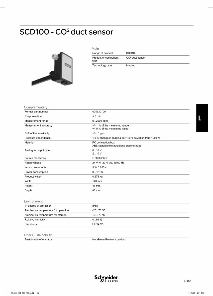
L-195
L
SCD100 - CO2 duct sensor
15434_131-236_150.indd 19515434_131-236_150.indd 195 11/1/13 4:51 PM11/1/13 4:51 PM

L-196
L
15434_131-236_150.indd 19615434_131-236_150.indd 196 11/1/13 4:51 PM11/1/13 4:51 PM

L-197
L
SCD100-DSCD100 - CO2 duct sensor - LCD
15434_131-236_150.indd 19715434_131-236_150.indd 197 11/1/13 4:51 PM11/1/13 4:51 PM

L-198
L
15434_131-236_150.indd 19815434_131-236_150.indd 198 11/1/13 4:51 PM11/1/13 4:51 PM

L-199
L
SCD Series
SPECIFICATIONS
Input Voltage . . . . . . .24 Vac, 20 to 36 Vdc Class 2Analog Output . . . . . . .4-20mA (clipped & capped)/
0-5VDC/0-10VDC (selectable) Sensor Current Draw . . . . . . 20-36VDC 40mA avg.,
105mA max.24VAC 50mA avg., 150mA max.
Operating Temperature Range . . . . . . . . .0° to 50°C (32° to 122°F)
Operating Humidity Range . . . . . . . . . . . . . .0-95% (noncondensing)
Housing Material . . . . . . . High impact ABS plastic
CO2 TransmitterSensor Type . . . . . Non-dispersive infrared (NDIR),
diffusion sampling Output Range . . . . . . . . . . . . . . . . . . . . 0-2000 ppm Accuracy . . . . . . . . ±1.5% of measurement range
±2% of measured value* Repeatability . . ±20 ppm ±1% of measured value Response Time . . . . . . . . . . . <60 seconds for 90%
step change RH TransmitterHS Sensor . . . Digitally profiled thin-film capacitive (32-bit mathematics); U.S. Patent 5,844,138 Accuracy . . . . . . ±2% from 10 to 80% RH @ 25°C; Hysteresis . . . . . . . . . . . . . . . . . . . . . . . 1.5% typical Linearity . . . . . . . . . . . . Included in Accuracy spec. Stability ±1% @ 20°C (68°F) annually, for two years Output Range . . . . . . . . . . . . . . . . . . 0 to 100% RH Temperature Coefficient . . . ±0.1% RH/°C above or below 25°C (typical)
TemperatureSensor Type . . . . . . . . . . . . . . . . . . . . . . ThermistorAccuracy . . . . . . . . . . . . . . . ±0.5°C (±1°F) typical
Relay Contacts: 1 Form C . . . . . . 1A@30VDC, resistive; 30W max.
Specified accuracy with 24VDC supplied power with rising humidity.
EMC Conformance:. . . . . . . . . . . . . . . . . . . . EN 6100-6-3: 2007 Class B. . . . . . . . . . . . . . . . . . . . EN 61326-1: 2006 Class B. . . . . . . . . . . . . . . . . . . . . . . . . . EN61000-6-2: 2005* Accuracy is specified at NTP (20°C at 101.3 kPa).
In the event that validation gas is required, the accuracy of validation gas mixture must be added to the sensor specified accuracy for absolute measurements.
Schneider Electric’s SCD series of duct mount sensors measure the levels of CO2, RH (if equipped) and temperature of air inside a duct. The CO2 sensor employs the Automatic Baseline Calibration (ABC) feature which enables the sensor to operate within accuracy specifications for the calibration interval of 5 years. The temperature element is warranted to meet accuracy specifications for a period of 5 years. RH equipped models of the SCD feature a replaceable humidity element that is warranted to meet accuracy specifications for a period of 1 year. HS2NX and HS2XX replaceable humidity elements are available through Schneider Electric. To maintain accurate functionality, keep all vents clear and free of dust, debris, etc.
6.7"(170 mm)
3.1"(78 mm)
7.8"(198 mm)2.4"
(61 mm)
10.2"(259 mm)
DIMENSIONS
15434_131-236_150.indd 19915434_131-236_150.indd 199 11/1/13 4:51 PM11/1/13 4:51 PM

L-200
L
INSTALLATION1. Choose a location to mount the sensor. The centerline of the housing must
be parallel to the direction of air flow in the duct.2. Use the mounting diagram to drill four holes in the duct for securing the
sensor.3. Insert the probe into the hole. Rotate the housing so that the widest surface
is perpendicular to the air flow.4. Attach the sensor to the duct using sheet metal screws. Make sure that the
gasket on the back of the housing is compressed between the housing and the duct for a secure fit.
5. Wire the device. See Wiring section.6. Configure the system using configuration section.
WIRING, RELAY, AND DIP SWITCH SETTINGS1. Feed control wire through grommeted
compression fitting on the bottom of the housing.
2. Remove terminal blocks by pulling the assemblies away from the main board.
3. Connect wires as shown and push terminal blocks back in to black receptacles.
4. Tighten compression fitting around control wire until sealed.
5. Refer to specifications for power requirements and relay rating.
6. Select mA or Volt output using selector switch.7. If Volt output is selected, select 5V (0-5VDC) or
10V (0-10VDC) using switch 1 on the 4 throw dipswitch.
8. Select a relay setpoint of 800, 1000 or 1200PPM of CO2 using switch 2 and 3 on the 4 throw dipswitch (see setpoint diagram for dipswitch settings).
9. Select deadband of 50PPM or 100PPM using switch 4 on the 4 throw dipswitch. This setting allows for additional flexibility when using the relay setpoint. The actual relay trip point is the setpoint PPM ± the deadband PPM. Example: If the relay setpoint is set for 1000PPM and the deadband is set for 50PPM, with dropping CO
2
levels the relay will trip at 950PPM (1000PPM – 50PPM), with rising CO
2 levels the relay will trip
at 1050 ppm (1000PPM + 50PPM).
1" diameter
CL
0.4" x .0.2"(typical)
6.7"(170 mm)
0.3"(7 mm)typ
1"(25 mm)typ
5.7"(144 mm)
3.1"(78 mm)
2.2"(55 mm)
Rotate the duct probeso the channeled side isperpendicular to the air flow of the duct
NC COMM NO RTD
RH OUT
GNDCO2 OUT
V+ TEMP OUT/RTD
mA
Volt
EnterDIP Switches
Deadband
Setpoint
Voltage Range
100 PPM50 PPM
5 V10 V
800 PPM 1000 PPM 1200 PPM
Observe handling precautions for static sensitivedevices to avoid damage to the circuitry whichwould not be covered under the factory warranty.
15434_131-236_150.indd 20015434_131-236_150.indd 200 11/1/13 4:51 PM11/1/13 4:51 PM

L-201
L
CALIBRATION PROCESS1. Remove cover and connect gas cylinder
hose to the plastic port located on sensing module. Note: only connect one sensor to the calibration gas cylinder at a time.
2. Set DIP switches 2 and 3 to the ON position to enable calibration.
3. Start flowing nitrogen gas (0 ppm CO2). Use a
flow rate of 0.3 to 0.5 liter/minute. 4. Push and hold Enter button until red LED lights
up.5. Calibrate until red LED turns off (approximately
5 min). Unit will return to normal operation when finished. Return DIP switches to Setpoint position (see Wiring, Relay, and DIP Switch Settings section) when calibration is complete.
ABC CALIBRATION ALGORITHM:ABC (Automatic Baseline Calibration) is a patented self-calibration feature that automatically adjusts the CO2 sensor to compensate for drift. When ABC is enabled, the sensor records the lowest reading within every 24-hour interval and compares these values over a running 7-day or 28-day period. If a statistically significant amount of drift is detected, the ABC applies an automatic correction factor. This enables the sensor to operate within specifications for the 5-year calibration interval.
ON POSITION. Recommended Setting. Use the ON setting for applications where the building is unoccupied within a 24-hour timeframe.
LOW POSITION. Use the LOW setting for buildings occupied 24 hours a day.
OFF POSITION. Not Recommended.
NOTE: After changing the ABC settings, power cycle the unit for changes to take effect.
HUMIDITY SENSOR REPLACEMENT
SCD models with optional RH have replaceable humidity sensors.
To Replace Humidity Sensor:1. Power down unit2. Remove SCD from duct
to access probe tip.3. Open tip of duct probe4. Slide old HS sensor off
pins5. Slide new HS sensor
onto pins.6. Re-install SCD in duct
and re-secure with screws provided.
7. Power unit back on
OUTPUT SCALINGOutput scaling: 0-2000 ppm
CO2 ppm 0-5 Volt Output
0-10 Volt Output
mA Output
Outside 300-500 0.75 to 1.25 1.5 to 2.5 6.4 to 8
Over-Ventilated
Under 600 under 1.5 Under 3 Under 8.8
ON LOW
ABC SettingsOFF
ON
LOW
OFF
ON
LOW
OFF
ON
LOW
OFF
Pins
HS Sensor
Lift to open tip of probe
Connect hose here
NITROGENGAS
Regulator Valve
mA
Volt
mA
Volt
mA
Volt
Push and hold button until red
LED lights up.
Red LED
Calibration Enable DIP switch setting
15434_131-236_150.indd 20115434_131-236_150.indd 201 11/1/13 4:51 PM11/1/13 4:51 PM

L-202
L
AVAILABLE PRODUCTSPart Number Model Number Duct Mounted CO2 Sensor with
Temp 2% RH LCD System5152300000 SCD110 x Vista 1.8K
5152302000 SCD110-D x x Vista 1.8K
5152304000 SCD110-H x x Vista 1.8K
5152306000 SCD110-D-H x x x Vista 1.8K
5152308000 SCD210 x I/NET 10K T2
5152310000 SCD210-D x x I/NET 10K T2
5152312000 SCD210-H x x I/NET 10K T2
5152314000 SCD210-D-H x x x I/NET 10K T2
5152316000 SCD510 x Continuum 10K T3
5152318000 SCD510-D x x Continuum 10K T3
5152320000 SCD510-H x x Continuum 10K T3
5152322000 SCD510-D-H x x x Continuum 10K T3
5152324000 SCD610 x Satchwell 10K T3 Resistor/Shunt
5152326000 SCD610-D x x Satchwell 10K T3 Resistor/Shunt
5152328000 SCD610-H x x Satchwell 10K T3 Resistor/Shunt
5152330000 SCD610-D-H x x x Satchwell 10K T3 Resistor/Shunt
5152332000 SCD810 x I/A 10K T3 w/Shunt
5152334000 SCD810-D x x I/A 10K T3 w/Shunt
5152336000 SCD810-H x x I/A 10K T3 w/Shunt
5152338000 SCD810-D-H x x x I/A 10K T3 w/Shunt
5152339010 HS2NX Replaceable RH Element, 2%, NIST.
5152339000 HS2XX Replaceable RH Element, 2%.
THERMISTOR TABLE°C °F Vista 1.8K I/NET 10K T2 Continuum 10K T3 Satchwell 10K T3
w/Resistor & ShuntI/A 10K T3 w/Shunt
-50 -58 82,207 692,644 447,497 9,781 10,736
-40 -40 42,848 344,702 242,599 9,604 10,523
-30 -22 23,563 180,148 136,484 9,318 10,180
-20 -4 13,585 98,324 79,472 8,884 9,663
-10 14 8,167 55,786 47,772 8,272 8,941
0 32 5,096 32,773 29,575 7,480 8,018
5 41 4,077 25,456 23,504 7,024 7,493
10 50 3,287 19,931 18,809 6,541 6,941
15 59 2,671 15,725 15,146 6,039 6,372
20 68 2,185 12,497 12,271 5,530 5,800
25 77 1,800 10,000 10,000 5,025 5,238
30 86 1,492 8,055 8,195 4,534 4,696
35 95 1,245 6,528 6,752 4,066 4,184
40 104 1,044 5,323 5,592 3,627 3,707
45 113 881 4,365 4,655 3,222 3,271
50 122 747 3,599 3,893 2,854 2,875
15434_131-236_150.indd 20215434_131-236_150.indd 202 11/1/13 4:51 PM11/1/13 4:51 PM

L-203
L
SCR Series
SPECIFICATIONS
Input Voltage . . . . . 24 VAC, 20 to 36 VDC Class 2Analog Output . . . . . . 4-20 mA (clipped & capped)/
0-5 VDC/0-10 VDC (selectable) Sensor Current Draw . . . . . 20-36 VDC 50 mA avg.,
150 mA max.24 VAC 120 mA avg., 170 mA max.
Operating Temperature Range . . . . . . . . . . . . . . . . . No Humidity option: 0° to 50°C (32° to 122°F)
WIth Humidity Option: 10° to 35°C (50° to 95°F) Operating Humidity Range . . . . . . . . . . . . . .0-95%
(noncondensing) Housing Material . . . . . . . High impact ABS plastic
CO2 TransmitterSensor Type . . . . . Non-dispersive infrared (NDIR),
diffusion sampling Output Range . . . . . . . . . . . . . . . . . . . . 0-2000 ppm Accuracy . . . . . . . . ±1.5% of measurement range
±2% of measured value* Repeatability . . ±20 ppm ±1% of measured value
Response Time . . . . . . . . . . . <60 seconds for 90% step change
RH TransmitterHS Sensor . . . .Digitally profiled thin-film capacitive
(32-bit mathematics); U.S. Patent 5,844,138 Accuracy . . . . . . . ±2% from 10 to 80% RH @ 25°C Hysteresis . . . . . . . . . . . . . . . . . . . . . . . 1.5% typical Linearity . . . . . . . . . . . . Included in Accuracy spec. Stability . . . . . . . . . . ±1% @ 20°C (68°F) annually,
for two years Output Range . . . . . . . . . . . . . . . . . . 0 to 100% RH Temperature Coefficient . . . ±0.1% RH/°C above or
below 25°C (typical)
TemperatureSensor Type . . . . . Thermistor (see thermistor table
for temperature curves)Accuracy . . . . . . . . . . . . . . . ±0.5°C (±1°F) typical
Relay Contacts1 Form C . . . . . 1 A@30 VDC, resistive; 30 W max.
Specified accuracy with 24 VDC supplied power with rising humidity. Thermistors are not compen-sated for internal heating of product.
EMC Conformance. . . . . . . . . . . . . . . . . . EN 61000-6-3: 2007 Class B; . . . . . . . . . . . . . . . . . . . . EN 61326-1: 2006 Class B; . . . . . . . . . . . . . . . . . . . . . . . . . .EN 61000-6-2: 2005
Environmental Rating. . . . . . . . . . . . . . . . . . . . . . . . . . . . . . .IP20; NEMA 1
* Accuracy is specified at NTP (20°C at 101.3 kPa).
3.2 “
(82 mm)
4.6 “
(116 mm)
0.9 “
(24 mm)
DIMENSIONS
Schneider Electric’s SCR series of wall mounted Living Space sensors measure the levels of CO
2, RH
(if equipped) and temperature of air inside a room. The CO
2 sensor employs the Automatic Baseline
Calibration (ABC) feature, which enables the sensor to operate within accuracy specifications for the calibration interval of 5 years. RH equipped models of the SCR feature a replaceable humidity element. HS2NX and HS2XX replaceable humidity elements are available through Schneider Electric. To maintain accurate functionality, keep all vents free of dust, debris, etc.
15434_131-236_150.indd 20315434_131-236_150.indd 203 11/1/13 4:51 PM11/1/13 4:51 PM

L-204
L
INSTALLATION1. Remove the outer cover by using a screwdriver to depress the two tabs on
the top of the device. This unclips the top half of the housing. Repeat on the tabs on the bottom of the device to remove the cover.
2. Remove the backplate by lifting up on the bottom of the board and pivoting it upward. Remove the board assembly from pivot pins.
3. Position the backplate vertically on the wall, 4.5 feet (1.5 m) above the floor. Locate away from windows, vents, and other sources of draft. If possible, do not mount on an external wall, as this might cause inaccurate temperature readings.
4. Mount the backplate onto the wall using screws (not included).5. Wire the device and configure output and DIP switches. See Wiring and
Configuration section. 6. Set ABC jumper to On or Low position. See ABC Calibration section.7. Re-affix board assembly onto backplate. Snap outer cover in place.
WIRING AND CONFIGURATION1. Connect wires as shown.2. Refer to specifications for power requirements and relay rating.3. Select mA or Volt output using selector switch.4. If Volt output is selected, select 5 V (0-5 VDC) or 10V (0-10 VDC)
using switch 1 on the 4 throw dipswitch.5. Select a relay setpoint of 800, 1000 or 1200 ppm of CO
2 using
switch 2 and 3 on the 4 throw dipswitch. The factory default is the “Relay Disabled” position.
6. Select deadband of 50 ppm or 100 ppm using switch 4 on the 4 throw dipswitch. This setting allows for additional flexibility when using the relay setpoint. The actual relay trip point is the setpoint ppm ± the deadband ppm. Example: If the relay setpoint is set for 1000 ppm and the deadband is set for 50 ppm, with dropping CO
2 levels the relay will trip at 950 ppm (1000 ppm – 50 ppm),
with rising CO2 levels the relay will trip at 1050 ppm (1000 ppm +
50 ppm).
25 24 23 22 21 11 12 13 14
POWER SUPPLY20-36 VDC, 24 VAC
Ther
mistor
Ther
mistor
Rela
y N.
C.
Rela
y N.O.
Power
Ground
CO2 Out
RH Out
Rela
y Co
mmon
Thermistor
Thermistor
Relay N.C.
Relay Common
Relay N.O.
CO2 In
RH In
Common
+
–
Setpoint
Deadband Voltage Range
100 PPM50 PPM
5 V10 V
800 PPMRelay Disabled 1000 PPM 1200 PPM
13 screwholes available; use a minimum of two for secure mounting.
If these two holes are selected, tighten the screws so that the screw heads are fully recessed in the housing.
DIP SwitchesVOLTmA
ON
LOW
ABC Settings
Insert screwdriver into tabs to release cover.
Observe handling precautions for static sensitivedevices to avoid damage to the circuitry whichwould not be covered under the factory warranty.
(default position)
15434_131-236_150.indd 20415434_131-236_150.indd 204 11/1/13 4:51 PM11/1/13 4:51 PM

L-205
L
ABC CALIBRATION ALGORITHM:ABC (Automatic Baseline Calibration) is a patented self-calibration feature that automatically adjusts the CO
2 sensor to compensate for
drift. The sensor records the lowest reading within every 24-hour interval and compares these values over a running 7-day or 28-day period. If a statistically significant amount of drift is detected, the ABC applies an automatic correction factor. This enables the sensor to operate within specifications for the 5-year calibration interval.
ON POSITION. Recommended Setting. Use the ON setting for applications where the building is unoccupied within a 24-hour timeframe.
LOW POSITION. Use the LOW setting for buildings occupied 24 hours a day.
NOTE: After changing the ABC settings, power cycle the unit for changes to take effect.
HUMIDITY SENSOR REPLACEMENT
SCR models with optional RH have replaceable humidity sensors.
To Replace Humidity Sensor:1. Disconnect power to the unit.2. Remove faceplate.3. Remove HS element by gently pulling from pin connector.4. Place new HS element onto pin connector. Orient as shown, or unit will not
function.5. Replace faceplate.
OUTPUT SCALING
CO2 Output scaling: 0-2000 ppm
CO2 ppm 0-5 Volt Output
0-10 Volt Output
mA Output
Outside 300-500 0.75 to 1.25 1.5 to 2.5 6.4 to 8
Over-Ventilated
Under 600 under 1.5 Under 3 Under 8.8
RH Output scaling: 0-100%
ON
LOW
ABC Settings
Top Side
Bottom Side
INDICATOR LED:SCR sensors equipped with the LED option have an LED on the faceplate that provides status indication.SCR sensors not equipped with the LED option do not have an LED indicator on the faceplate (Blank versions). They do, however, have internal LEDs that provide status indication similar to the LED versions.
Green Normal Operation
Yellow CO2 levels have exceeded
setpoint (if enabled)
Flashing Yellow Out of range or diagnostic event detected
Indicator LED(if equipped)
15434_131-236_150.indd 20515434_131-236_150.indd 205 11/1/13 4:51 PM11/1/13 4:51 PM

L-206
L
AVAILABLE PRODUCTS
Part Number
Model Number
Wall Mounted CO2 Sensor withLED Temp 2% RH System
x x TAC Vista
x x x TAC Vista
5152420000 SCR110B x TAC Vista
5152422000 SCR110B-H x x TAC Vista
x x TAC I/NET
x x x TAC I/NET
5152424000 SCR210B x TAC I/NET
5152426000 SCR210B-H x x TAC I/NET
x x Andover Continuum
x x x Andover Continuum
5152428000 SCR510B x Andover Continuum
5152430000 SCR510B-H x x Andover Continuum
x x Satchwell
x x x Satchwell
5152432000 SCR610B x Satchwell
5152434000 SCR610B-H x x Satchwell
x x TAC I/A Series
x x x TAC I/A Series
5152436000 SCR810B x TAC I/A Series
5152438000 SCR810B-H x x TAC I/A Series
5152339010 HS2NX Replaceable RH Element, 2%, NIST
5152339000 HS2XX Replaceable RH Element, 2%
THERMISTOR TABLE
°C °F TAC Vista 1.8K
TAC I/NET 10K T2
Continuum 10K T3
Satchwell 10K T3 w/Resistor & Shunt
TAC I/A Series10K T3 w/Shunt
0 32 5,096 32,773 29,575 7,480 8,018
5 41 4,077 25,456 23,504 7,024 7,493
10 50 3,287 19,931 18,809 6,541 6,941
15 59 2,671 15,725 15,146 6,039 6,372
20 68 2,185 12,497 12,271 5,530 5,800
25 77 1,800 10,000 10,000 5,025 5,238
30 86 1,492 8,055 8,195 4,534 4,696
35 95 1,245 6,528 6,752 4,066 4,184
40 104 1,044 5,323 5,592 3,627 3,707
45 113 881 4,365 4,655 3,222 3,271
50 122 747 3,599 3,893 2,854 2,875
15434_131-236_150.indd 20615434_131-236_150.indd 206 11/1/13 4:51 PM11/1/13 4:51 PM

M-207
M
SL-2000 Series
�������������� ������������ ���������������� ���������
����APPROVED���������
�������� ������������������ ���������������������� �������� ������������������������������������ ��������������� ��������� �������� �������������������������� !"����� ����"���������#�$��� ���������%� �������������������� &���������� ��� �������������������������������������� ������������������������ � ��� #���� #��������'�� &�"�������� � ��� ������� ������'������������������ ��������������&���������� ��� �����������������������������������(�������� #�� �'����� �����)*+!������������ ���������������� ������������� &�,�������������� ����������������������������� ���� � ����� ����� #� ����� #������� ���� ���������� ������� �-�� ������� '����� ������ �������� &
������������ ������������������ ������������� ����������� ������������������ ����������������������������� ������������� &�$��� ��� �����������������������������������(�������� #�� �'����� �����)*+!������������ ���������������� ������������� &�,������������� ����������������������������� ���� ����� ����� #� ����� #�������� ���� ���������� ������ �-�� ������� '����� ������ �������� &
��������� ��'�*��'�����������.��/����$���0����������+����������������� ��� ����������������� ����'����1�2���&-���
� ,���������������� .�3 !"#�114 !"#�2 !"#�2 �"� $������������������3����� �������������������� � +��������������5�� ��+���6� ���������' ����� ������ �����'��������������������
� $� ��������� ���������������������������������� ������������������������ ������� ����'������ ������������������� ������������ � *�� ������7��������������������������� ����������������
� 8�������� �������������9���������������:� 8����'������ ��������������������������� � *�������������' ������������������������������ '��������������������������
� ,����14������������ ���� ����������� "����������'��������;+�'����������������� ���
� %� ��� '������ ��� ������������� �� '����<���������������� ���(������������������������������
� �������� ��� ����������������� �������������� ������� =����������� ���������������������������� �������������
� 7>������������������� ����������(����������������������� ����
� "��������������� ������������ �������� ���� =�#�"�*8�����87!��� ���� "������#������'������ �0������ ���'��� ���������� � � ���� ����1!������5"6�������������� � 1� ������1!������5"6���������������� � "������������������'����2��������� ���' � �������������������������� ���' � ���������5�������� ����6�=�?@� ������������������� $���������������5+����$�6���������������������0����������
� �� ����������������������������� )������������� ����� ���������� ���������� "����������'�������������������������������������� � ���
� $���0����������+������������� �� ��� ����������
15434_131-236_150.indd 20715434_131-236_150.indd 207 11/1/13 4:51 PM11/1/13 4:51 PM

M-208
M
������ The information contained in this document is intended only as a summary and is subject to change without notice. The products described have specific instructional/installation documentation, which covers various technical, approval, code, limitation and liability information. Copies of this documentation along with any general productwarning and limitation documents, which also contain important information, are provided with the product and are also available from Air Products and Controls Inc.The information contained in all of these documents should be considered before specifying or using the products. Any example applications shown are subject to themost current enforced local/national codes, standards, approvals, certifications, and/or the authority having jurisdiction. All of these resources, as well as the specificmanufacturer of any shown or mentioned related equipment, should be consulted prior to any implementation. For further information or assistance concerning the products,contact Air Products and Controls Inc. Air Products and Controls Inc. reserves the right to change any and all documentation without notice.
����
�������� ���������MODEL NUMBER: SL-2000-N Ionization: 230VAC, 115VAC, 24VAC, 24VAC/DC
SL-2000-P Photoelectric: 230VAC, 115VAC, 24VAC, 24VAC/DCDETECTOR MODEL NUMBER: S65 Ionization Detector Head 55000-225APO
S65 Photoelectric Detector Head 55000-328APOSAMPLING TUBES: STN-2.5 Sampling tube for 6" to 2.5' duct width
STN-5.0 Sampling tube for 2.5' to 5.0' duct widthSTN-10.0 Sampling tube for 5.0' to 10.0' duct width
ACCESSORIES: MS-Series remote accessories, WP-2000 weatherproofenclosures, and T-PB power supplies (Available fromAir Products and Controls Inc.)
POWER REQUIREMENTS: (Without accessories) 230VAC 7.9 mAStand By: 115VAC 13.8 mA
24VAC 39.4 mA24VDC 13.5 mA
Alarm Current: 230VAC 16.0 mA115VAC 27.0 mA24VAC 59.3 mA24VDC 128.7 mA
RELAY CONTACT RATING:Alarm Contacts: 2 sets form “C” rated at 10 Amps @ 115VAC Resistive
1 set form “A” rated at 2 AmpsTrouble Contacts: 1 set form “C” rated at 10 Amps @ 115VAC ResistiveAIR VELOCITY: 100 to 4,000 ft./min.AMBIENT TEMPERATURE: Model SL-2000-N 32ºF to 155ºF (0ºC to 70ºC)
Model SL-2000-P 32ºF to 100ºF (0ºC to 38ºC)HUMIDITY: 10% to 85% R.H. No CondensationWIRING: #14 to #22 AWG terminalsAPPROVALS: Underwriters Laboratories Listed (UL268A;UROX.S2829)
CSFM Listed (3240-1004:105)MEA Listed (73-92-E;VOL.27)
MATERIAL: Grey plastic backbox, clear plastic coverDIMENSIONS: L-13 1/ 2" X H-4 1/ 2" X D-2 1/ 4"MAX. NET WT.: 2 1/ 2 lbs.RADIOACTIVE ELEMENT: For SL-2000-N (Ionization) Americium 241; 0.9 Micro-Curie
Do Not Expose to Corrosive AtmospheresHARDWARE: 7" exhaust tube, sampling tube end cap, mounting template
and mounting hardware included
���������������������� ���������A !�������� ������������� � ��������!���+������ �����"������ �$��&���������� &��*�������0�������������� ������������������� ����������&*������������������������� ������������������� ����������&�������������� � ���������� �������=����'����� ������������ �����=��?@!&������������ � ����������������������������� ������1��������������������2#����������������&
A � ������������������������������'����� �����������������������������������&A !���������� ��� '����� ��������������������������������������&A �������������� �����������(���������������������� ���� ����� �'������� ���������������&A ������� ���� �������������������������� ��'�����'��������������������������������0������������������� &A ������������������� � ��������������� ���'��������������������������B?� ���'&��������� � ���������������������������������#����������������������� #� �����-������������������ ��� '����&��!���'�������� ���������'�������������� ��������������� &
A !������������� ������������������������'��������������� �������������&A !����������� ������� ������������������'���������������������������� �������������&
15434_131-236_150.indd 20815434_131-236_150.indd 208 11/1/13 4:51 PM11/1/13 4:51 PM

N-209
N
SatchwellTM
WATER AND AIR FLOW SWITCHES
The Satchwell water flow switch is designed to monitor water flow in pipe diameters from 1" up to a maximum of 6" and is factory set at a minimum value (see table). The switching value can be increased as required. The water flow switch can be mounted in a short necked welding socket or in a tee with a short branch. It is not possible to use a swept tee as this will interfere with paddle movement.The air flow switch has a paddle that can be trimmed if the air flow is above 5m/s.Both the water and air flow switches are SPDT types.
SFW, SFA
15434_131-236_150.indd 20915434_131-236_150.indd 209 11/1/13 4:51 PM11/1/13 4:51 PM

N-210
N
SPECIFICATION
SFW SWITCHING VALUES
SFW SWITCHING VALUES
CONSTRUCTION
Types: SFW1251 – Water flow switch 1" to 6" pipe diameterSFA1451 – Air flow switch
Factory Flow Setting: SFW: Set at minimum (see table), depends on the pipe diameter.SFA : Set at minimum 1m/s, 2.5m/s if the paddle is trimmed
Differential: See table below:
Pipe Diameter in Inches Minimum Cut-in Value m3/Hour
Minimum Cut-out Value m3/Hour
Maximum Cut-in Value m3/Hour
Maximum Cut-out Value m3/Hour
1 1.0 0.6 2.1 2.0
1.25 1.3 0.8 3.0 2.8
1.5 1.7 1.1 4.0 3.7
2 3.1 2.2 6.1 5.7
2.5 4.0 2.7 7.0 6.5
3 6.2 4.3 11.4 10.7
4 14.7 11.4 29.0 27.7
5 28.4 22.9 55.6 53.3
6 43.1 35.9 85.1 81.7
Paddle Minimum Cut-in Value m/s
Minimum Cut-out Value m/s
Maximum Cut-in Value m/s
Maximum Cut-out Value m/s
Untrimmed <5 m/s 2.0 1.0 9.2 8.0
Trimmed >5 m/s 3.5 2.5 10.7 9.5
Maximum Differential Pressure: SFW :11 mbarContact: Single Pole Double Throw (SPDT) Contact Rating: 15A resistive, 8A inductive @ 24 to 250VacAmbient Temperature Limits: –20 to +85°C
Maximum fluid or air temperature +85°C
Cable Entry: PG 11 cable glandHead Protection Class: IP 65Cover: Impact resistant plasticCasing: Galvanised steelLever: BrassPaddle: Stainless Steel
15434_131-236_150.indd 21015434_131-236_150.indd 210 11/1/13 4:51 PM11/1/13 4:51 PM

N-211
N
WARNING - ISOLATE ALL WIRING BEFORE REMOVING THE COVER AS MAINS VOLTAGES ARE PRESENT AT THE TERMINALS.
INSTALLATIONSFW - WATER FLOW SWITCH1. Select a point in the pipe that has no elbows, bends or other obstructions that may cause turbulence. The pipe must be straight for at least
5 pipe diameters up and downstream of the flow switch.2. The flow switch should be mounted in a horizontal pipe. Do not mount the flow switch directly under the pipe. If the flow switch is mounted
in a vertical section of pipe the set value will differ from the settings as the water will have to move the weight of the paddle as well as the switch tension.
3. If the pipe diameter is 1, 2 or 3" then remove any unwanted paddles. If the pipe is 1.25", 1.5", 2.5", 4", 5" or 6" in diameter then use the template below to trim the 6 paddle supplied and fit it to the SFW, keep the existing paddles on the SFW as this will help to stiffen the new longer paddle.
4. Fit the flow switch in to the pipe using a short neck welding socket or a tee with a short branch. It is not possible to use a swept tee or a long branch tee.
5. Check that the paddle does not touch the pipe or any other obstruction.6. Ensure the flow direction arrow is correct for the water flow.7. Flush out the system thoroughly.8. Use the minimum quantity of jointing materials.9. Remove the cover and wire the switch according to Fig.1. THE EARTH TERMINAL MUST BE CONNECTED.10. Do not adjust the set value below the minimum setting as shipped from the factory.11. Replace the cover.
SFA - AIR FLOW SWITCH1. Select a point in the duct that has no bends or other obstructions that may cause turbulence. The duct must be straight for at least 5 duct
diameters up and downstream of the flow switch.2. The flow switch should be mounted in a horizontal duct. Do not mount the flow switch directly under the duct. If the flow switch is mounted
in a vertical section of duct the set value will differ from the settings as the air will have to move the weight of the paddle as well as the switch tension.
3. If the flow rate is to be above 5m/s then the paddle should be trimmed as marked. This will increase the effective switching values by 1.5m/s.4. Cut a slot in the duct to accept the paddle. Use the gasket supplied to seal the duct.5. Check that the paddle does not touch the duct or any other obstruction.6. Ensure the flow direction arrow is correct for the air flow.7. Remove the cover and wire the switch according to Fig.1. THE EARTH TERMINAL MUST BE CONNECTED.8. Do not adjust the set value below the minimum setting as shipped from the factory.9. Replace the cover.
BASIC CONNECTIONS
Set value adjustment. Factory set at minimum do not adjust below this value.
1
4
2
Red Blue
White
Fig.1
15434_131-236_150.indd 21115434_131-236_150.indd 211 11/1/13 4:51 PM11/1/13 4:51 PM

N-212
N
DIMENSION DRAWINGS
PADDLES
Dimensions in mm Weights:SFW 760gSFA 410g
SFW SFA
WARNINGS - THESE FLOW SWITCHES ARE MAINS OPERATED DEVICES. LOCAL WIRING REGULATIONS AND USUAL SAFETY PRECAUTIONS MUST BE OBSERVED. NOTE EARTHING REQUIREMENTS.ISOLATE ALL WIRING BEFORE REMOVING THE COVER AS MAINS VOLTAGES ARE PRESENT AT THE TERMINALS.Cautions• Do not apply any voltages until a qualified technician has checked
the system and the commissioning procedures have been completed.
• If any equipment covers have to be removed during the installation of this equipment, ensure that they are refitted after installation to comply with UL and CE safety requirements.
• Do not exceed the maximum ambient temperature.• Interference with parts under sealed covers invalidates the
guarantee.• Design and performance of TAC Satchwell equipment is subject to
improvement and therefore liable to alteration without notice.• Information is given for guidance only and TAC Satchwell does not
accept responsibility for the selection and installation of its products unless information has been given by the Company in writing relating to a specific application.
• A periodic system and tuning check of the control system is recommended. Please contact your local sales office for details.
Fitted
Supplied
15434_131-236_150.indd 21215434_131-236_150.indd 212 11/1/13 4:51 PM11/1/13 4:51 PM

N-213
N
SSF901 +902
15434_131-236_150.indd 21315434_131-236_150.indd 213 11/1/13 4:51 PM11/1/13 4:51 PM

N-214
N
15434_131-236_150.indd 21415434_131-236_150.indd 214 11/1/13 4:51 PM11/1/13 4:51 PM

O-215
O
SLR320
SPECIFICATIONS
Part Number . . . . . . . . . . . . . . . . . . . . . 006920630
Range . . . . . . . . . . . . . . . . . . . . . . . . . . . . . . . N/A
Jumper: 0-400 lx . . . . . . . . . . . . . . . . . . . .0-400 lx
Jumper: 0-20 klx . . . . . . . . . . . . . . . . . . . .0-20 klx
Signal Output . . . . . . . . . . . . . . 4-20 mA or 0-10 V
Materials
Housing . . . . . . . . . . . . . . . . . . . .polyamide plastic
Enclosure Rating . . . . . . . . . . . . . . . . . . . . . . IP 30
Dimensions in mm . . . . . . . . . . . . . . . .see Figure 1
Weight . . . . . . . . . . . . . . . . . . . . . . . . . . . . . 100 g, weight includes standard packing, in brackets
Power . . . . . . . . . . . . . .24 Vac +/- 10%. 15-36 Vdc
Accuracy . . . . . . . . . . . . . . . . . . . . . . . . . . .+/- 5%
at ambient temp of 25° C
Wavelength at max. sensitivity . . . . . . . . . . 600 nm (standard light A/2854K coulour temp)
Temperature Dependence . . . . . . . . . . . . . .+/- 5%
at ambient temp. of 25° C and UG = 24 V
Load Resistance . . . . . . . . . . . . . . . . . . .> 50 kohm
Current Consumption . . . . . . . . . . . . . . . . . . typical Range 0-400 lx . . . . . . . . . . . . . . . . . . . . . . . . 8 mA
Range 0-20 klx . . . . . . . . . . . . . . . . . . . . . . . 13 mA
Ambient Temperature . . . . . . . . . . . . . -20° C (-4° F) to 70° C (158°F)
Standards: EMC . . . . . . . EN 50081-1, EN 50082-1
Room Light Transmitter
The SLR320 is an electronic light transmitter that converts a lux measurement into an electric current signal of 4–20 mA or a voltage signal of 0-10 V.
It has two sensitivity ranges to suit different light levels: 0–400 lx (e.g. for controlling outdoor lighting), and 0–20 klx (for controlling sunshade systems).
The transmitter is delivered as a complete unit, comprising the sensing element, an amplifier mounted in a housing.
The transmitter is intended for wall mounting indoors.
The sensitivity peak is for light at an angle of incidence of 0° to the perpendicular. The sensor has the same spectrum sensitivity peak as the human eye.
The transmitter is connected with a 2-wire cable when configured for 4 to 20mA, which serves both as power supply and for signal transmission, and 3-wires for a 0 to 10Vdc output configuration.
15434_131-236_150.indd 21515434_131-236_150.indd 215 11/1/13 4:51 PM11/1/13 4:51 PM
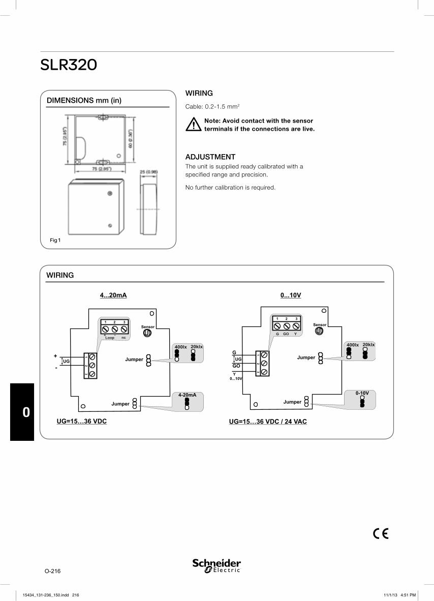
O-216
O
SLR320
WIRING
WIRING
Cable: 0.2-1.5 mm2
Note: Avoid contact with the sensor terminals if the connections are live.!
ADJUSTMENTThe unit is supplied ready calibrated with a specified range and precision.
No further calibration is required.
DIMENSIONS mm (in)
Fig 1
15434_131-236_150.indd 21615434_131-236_150.indd 216 11/1/13 4:51 PM11/1/13 4:51 PM

O-217
O
SLO320
Outdoor Light Transmitter
SLO320 is an electronic light transmitter that converts a lux measurement into an electric signal of 4-20 mA or 0–10 V.
It has two sensitivity ranges to suit different light levels: 0–400 lx (e.g. for controlling outdoor lighting), and 0–20 klx (for controlling sunshade systems).
The transmitter is delivered as a complete unit, comprising the sensing element, an amplifier mounted in a housing, which is resistant to ultra-violet light.
The transmitter is intended for wall mounting outdoors.
The sensitivity peak is for light at an angle of incidence of 0° to the perpendicular.
The sensor has the same spectrum sensitivity peak as the human eye.
The transmitter is connected with a 2-wire cable when configured for 4 to 20mA, which serves both as power supply and for signal transmission, and 3-wires for a 0 to 10Vdc output configuration..
SPECIFICATIONSRange
Jumper: 0-400 lx . . . . . . . . . . . . . . . . . . . .0-400 lx
Jumper: 0-20 klx . . . . . . . . . . . . . . . . . . . .0-20 klx
Signal Output . . . . . . . . . . . . . . 4-20 mA or 0-10 V
Materials
Housing . . . . . . . . . . . . . . . . . . . .polyamide plastic
Enclosure Rating . . . . . . . . . . . . . . . . . . . . . . IP 65
Weight . . . . . . . . . . . . . . . . . 100 g, weight includes standard packing, in brackets
Power . . . . . . . . . . . . . .24 Vac +/- 10%. 15-36 Vdc
Accuracy . . . . . . . . . . . . . . . . . . . . . . . . . . . +/- 5% at ambient temp of 25° C
Wavelength at max. sensitivity . . . . . . . . . . 600 nm (standard light A/2854K coulour temp)
Temperature Dependence . . . . . . . . . . . . . .+/- 5%
at ambient temp. of 25°C and UG = 24 V
Load Resistance . . . . . . . . . . . . . . . . . . .> 50 kohm
Current Consumption . . . . . . . . . . . . . . . . . . typical
Range 0-400 lx . . . . . . . . . . . . . . . . . . . . . . . . 8 mA
Range 0-20 klx . . . . . . . . . . . . . . . . . . . . . . . 13 mA
Ambient Temperature . . . . . . . . . . . -20° C (-4° F) to 70° C (158°F)
Standards: EMC . . . . . . . EN 50081-1, EN 50082-1
PART NUMBER
Part Number Model Number
006920640 SLO320
15434_131-236_150.indd 21715434_131-236_150.indd 217 11/1/13 4:51 PM11/1/13 4:51 PM
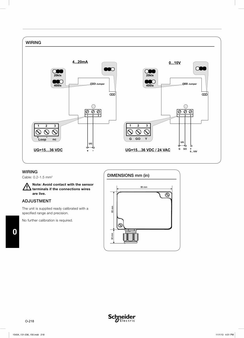
O-218
O
WIRING
WIRINGCable: 0.2-1.5 mm2
Note: Avoid contact with the sensor terminals if the connections wires are live.
ADJUSTMENT
The unit is supplied ready calibrated with a specified range and precision.
No further calibration is required.
!
DIMENSIONS mm (in)
15434_131-236_150.indd 21815434_131-236_150.indd 218 11/1/13 4:51 PM11/1/13 4:51 PM

P-219
P
Multical® 602 & ultraflow® 14/54 Heating/Cooling Meter
MULTICAL® 602 and ULTRAFLOW® 14/54 are usedfor measurement of cooling or combined heat/cool-ing in all water based plants with flow temperatures from 2°C to 50°C/ 90°C and with ULTRAFLOW®
14/54 between qp 1.5 m³/h and qp 400 m³/h.
The meter is simple to install, read and test.MULTICAL® 602 and ULTRAFLOW® 14/54 con-tributes to keeping the annual operating costs at a minimum with its unique combination of high measuring accuracy and long lifetime.
MULTICAL® 602 receives volume pulses from theconnected ULTRAFLOW® 14/54 and calculates theenergy for every predetermined water volume. Theenergy calculation includes temperature measure-ments in flow and return as well as correction fordensity and heat content according to EN 1434.MULTICAL® 602 and ULTRAFLOW® 14/54 can besupplied by either 24 VAC, 230 VAC or battery.
MULTICAL® 602 can be extended with two internalmodules – a top module with pulse outputs, M-Bus or valve control and a base module with M-Bus, radio, LonWorks or 0/4…20 mA outputs. Further-more, the base module includes two additional pulse inputs for connection of water and electricity meters, making it possible to collect all consump-tion data with one single automatic data reading.
ULTRAFLOW® 14/54 is a static flow sensor based on the ultrasonic measuring principle for use in cooling installations where water is used as the energy conveying medium.
ULTRAFLOW® 14/54 is not suitable for use with other media than water and should therefore not be used with e.g. anti-freeze additives like glycol.The flow is measured using bidirectional ultrasonictechnique based on the transit time method, withproven long-term stability and accuracy. Twoultrasonic transducers are used to send the soundsignal both against and with the flow direction.The ultrasonic signal travelling with the flow direc-tion reaches the opposite transducer first. Thetime difference between the two signals can beconverted into a flow velocity and thus a volume.
FEATURES
15434_131-236_150.indd 21915434_131-236_150.indd 219 11/1/13 4:51 PM11/1/13 4:51 PM

P-220
P
1 CALCULATOR FUNCTIONS
1.1 Energy calculation®
1.2 Application®
®
1.3 Min. and max. flow and power ®
1
E [Wh] = V x x k x 1,000
E [kWh] = E [Wh] / 1,000
E [MWh] = E [Wh] / 1,000,000
E [GJ] = E [Wh] / 277,780
E [Gcal] = E [Wh] / 1,163,100
CLOSED THERMAL SYSTEM
1 flow sensor
15434_131-236_150.indd 22015434_131-236_150.indd 220 11/1/13 4:51 PM11/1/13 4:51 PM

P-221
P
1.4 Set/reset function
DateHourInput A (preset of register)Input B (preset of register)Meter no. of Input AMeter no. of Input BPulse value for Input APulse value for Input BPrimary M-Bus addressOperating hour counter (reset)Info-event counter (reset)
1
The upper push button is used to switch between the primary readings. The consumers typically use the first primary read-ings in connection with self-reading for billing purposes.
The lower push button is used to show secondary information on the se-lected primary reading.
Info code Description
0 No irregularities1 Supply voltage connected after cut off4 T2 sensor outside range, short-circuited or cut off8 T1 sensor outside range, short-circuited or cut off16 Flow sensor V1, datacomm error, signal too low or wrong flow direction2048 Flow sensor V1, wrong meter factor4096 Flow sensor V1, signal too low (Air)16384 Flow sensor V1, wrong flow direction
DISPLAY FUNCTIONS
15434_131-236_150.indd 22115434_131-236_150.indd 221 11/1/13 4:51 PM11/1/13 4:51 PM

P-222
P
1.5 Data loggers®
Data logging interval Data logging depth Logged value
Yearly logger 15 years Counter registers (as seen on the display)Monthly logger 36 months Counter registers (as seen on the display)Daily logger 460 days Consumption (increase)/dayHourly logger 1392 hours Consumption (increase)/hourProgrammable data logger (option) 1080 loggings (e.g. 45 days´ hour loggings
or 11 days‘ 15 min. loggings)Up to 40 optional registers and values
Info logger 50 events Date, Info code, E1, E3, Time
1.6 Pulse inputs VA and VB®
1.7 Voltage supply®
1.8 Plug-in modules®
1.9 Programming and testing® ®
®
1.10 Tariff functions®
15434_131-236_150.indd 22215434_131-236_150.indd 222 11/1/13 4:51 PM11/1/13 4:51 PM

P-223
P
Pulse inputs VA and VB Water meter connection Electricity meter connection
VA: 65-66 and VB: 67-68
FF(VA) and GG(VB) = 71…90
FF(VA) and GG(VB) = 50…60
Pulse input 680 k pull-up to 3.6 V 680 k pull-up to 3.6 V
Pulse ON < 0.4 V for > 30 msec. < 0.4 V for > 30 msec.
Pulse OFF > 2.5 V for > 100 msec. > 2.5 V for > 100 msec.
Pulse frequency < 1 Hz < 3 Hz
Electrical isolation No No
Max. cable length 25 m 25 m
FF(VA) and GG(VB) = 01…40
Pulse input 680 k pull-up to 3.6 V
Pulse ON < 0.4 V for > 200 msec.
Pulse OFF > 2.5 V for > 500 msec
Pulse frequency < 1 Hz
Electrical isolation No
Max. cable length 25 m
Requirements to external contact
Leakage current at function open < 1uA
Pulse outputs CE and CV – via top module 67-08
Type Open collector (OB)
Pulse length 32 msec. or 100 msec. (32 msec. for 67-06)
External voltage 5…30 VDC
Current 1…10 mA
Residual voltage UCE 1 V at 10 mA
Electrical isolation 2 kV
Max. cable length 25 m
2 ELECTRICAL DATA
Typical accuracyCalculator . . . . . . . . . . . . . . . EC ±(0.15 + 2/ )%Sensor set . . . . . . . . . . . . . . . . .ET ±(0.4 + 4/ )%Flow sensor Class 2 . . . . . . EF ±(2 + 0,02 x qp/q)%
Max 5%
Supply voltage . . . . . . . . . . . . . . .3.6 VDC ± 0.1 VBattery . . . . . . . . . . . . . . . 3.65 VDC, D-cell lithiumStand-by current. . . . . . . . . . . . . . . . . . . . < 85 μAReplacement intervalMounted on wall . . . . . . . . 12 years @ tBAT < 35°C The replacement interval is reduced when using
data modules, frequent data communication or high ambient temperature
Mains supply . . . . . . . . . 24 VAC ±50%, 50/60 HzInsulation voltage . . . . . . . . . . . . . . . . . . . . . . 4 kVPower supply . . . . . . . . . . . . . . . . . . . . . . . . < 1W
Backup supply . . . . . . . . . . . . . . Integral super-cap eliminates operational stop-down due to short-term
power cutsEMC data . . . . . . . . . . Domestic and light industrial
Calculator dataDisplay . . . . . . . . . . . . . . . . . . . LCD – 7 (8) digits
with a digit heigth of 7.6 mmResolution . . . . . . . . . . . . . . 9999.999 – 99999.99
– 999999.9 – 9999999 Energy units . . . . . . . . . . . . . . . . . . . . . . . . . MWhTemperature range . . . . . . . . . . . . . . . : 2...180°CDifferential range . . . . . . . . . . . . . . . . :3...170 K Data logger (Eeprom)Standard . . . . .1392 hours, 460 days, 36 months,
15 years, 50 info codesOption . . . . . . . . . . . . . . . . . . . . Data loggers with
Programmable intervalClock/calendarStandard . . . . . . . . . . . . Clock calendar, leap-year
compensation, target date
Data communicationStandard . . . . .KMP protocol with CRC16 used for
optical communication and for top and base modules
Power in temperature sensors . . . . .< 10 μW RMS
Temperature measurementSensor inputs T1, T2Measuring range . . . . . . . . . . . . . . 0.00…185.00°CMax. cable lengthsPt500, 2-wire . . . . . . . . . . . . . 2 x 0.25 mm²: 10 m
15434_131-236_150.indd 22315434_131-236_150.indd 223 11/1/13 4:51 PM11/1/13 4:51 PM

P-224
P
3 FLOW DATA HEAT COOLING
*) The meter factor can be seen on the label on the side of the meter. **) Saturation flow. Max. pulse frequency 128 Hz is maintained at higher flow rates.
4 PRESSURE LOSS
*) q=kv x p
Graph qp [m3/h] Nom. diameter Kv *) [email protected] bar [m3/h]
A 1.5 DN15 & DN20 3.2 1.6
B 2.5 & 3.5 & 6 DN20 & DN25 13.4 6.7
C 10 & 15 DN40 & DN50 40 20
D 25 DN65 102 51
E 40 DN80 179 90
F 60 & 100 DN100 373 187
G 150 & 250 DN150 1060 530
H 400 DN150 2000 1000
I 400 DN200 & DN250 4040 2020
Nom. Flow qp [m3/h]
Nom. Diameter
Meter factor *) [imp./l]
Dynamic range qi:qp
qs :qp Flow @125 Hz **) [m3/h]
p@qp [bar] Min. cut off [l/h]
Type
1.5 DN15 &
DN20
100 1:100 2:1 4.5 0.22 3 ULTRAFLOW 14
2.5 DN20 60 1:100 2:1 7.5 0.03 5 ULTRAFLOW 14
3.5 DN25 50 1:100 2:1 9 0.07 7 ULTRAFLOW 14
6 DN25 25 1:100 2:1 18 0.2 12 ULTRAFLOW 14
10 DN40 15 1:100 2:1 30 0.06 20 ULTRAFLOW 14
15 DN50 10 1:100 2:1 45 0.14 30 ULTRAFLOW 14
25 DN65 6 1:100 2:1 75 0.06 50 ULTRAFLOW 14
40 DN80 5 1:100 2:1 90 0.05 80 ULTRAFLOW 14
60 DN100 2.5 1:100 2:1 180 0.03 120 ULTRAFLOW 14
100 DN100 1.5 1:100 2:1 300 0.07 200 ULTRAFLOW 14
150 DN150 1 1:100 2:1 450 0.02 300 ULTRAFLOW 54
250 DN150 0.6 1:100 2:1 750 0.055 500 ULTRAFLOW 54
400 DN150 0.4 1:100 2:1 1125 0.04 800 ULTRAFLOW 54
400 DN200 0.4 1:100 2:1 1125 0.01 800 ULTRAFLOW 54
400 DN250 0.4 1:100 2:1 1125 0.01 800 ULTRAFLOW 54
15434_131-236_150.indd 22415434_131-236_150.indd 224 11/1/13 4:51 PM11/1/13 4:51 PM

P-225
P
5 PRESSURE LOSS CHART
p ULTRAFLOW® 14/54
0.01
0.1
1
0.1 1 10 100 1000
Δp [
bar]
Flow [m³/h]
Δp ULTRAFLOW® 54
A B C D E F G H I
15434_131-236_150.indd 22515434_131-236_150.indd 225 11/1/13 4:51 PM11/1/13 4:51 PM

P-226
P
6 MECHANICAL DATA
®
®
7 MATERIALS
MULTICAL® 602Top cover . . . . . . . . . . . . . . . . . Thermoplastic, PCBase unit . . ABS with T PE gaskets (Thermoplastic
elastomer) elastomer TPE gasketsPrint box . . . . . . . . . . . . . . . . . Thermoplastic, ABSWall bracket . . . . . . . . Thermoplastic, PC 30% GF
ULTRAFLOW® 14/54Wetted parts
ULTRAFLOW® 14/54, qp 1.5 m3/hHousing, gland . . . . . Dezincification resistant brassTransducers . . . . . . . Stainless steel, W.no. 1.4401Gaskets . . . . . . . . . . . . . . . . . . . . . . . . . . . . EPDMReflectors . . . . . . Thermoplastic, PES 30% GF and
stainless steel, W.no. 1.4301Measuring pipe . . . . . .Thermoplastic, PES 30% GF
ULTRAFLOW® 14/54, qp 2.5 to 100 m³/hHousing, gland . . . . . Dezincification resistant brassHousing, flange . . . . . . . . . . . . . Red brass, RG5 or
stainless steel W.no. 1.4308 (see Order specification)
Transducers . . . . . . . Stainless steel, W.no. 1.4401Gaskets . . . . . . . . . . . . . . . . . . . . . . . . . . . . EPDMMeasuring pipe . . . . . .Thermoplastic, PES 30% GFReflectors . . . . . . . . . Stainless steel, W.no. 1.4301
Additional sizesUltraflow 54 . . . . . . . . . . . . . . . . . . .qp 150 to 400Housing . . . . . . . . . . . stainless steel w.no. 1.4308Transducer holder . . . . stainless steel w.no. 1.4308Transducer . . . . . . . . . . . . . . . . . . . . . . . . TitaniumGasket . . . . . . . . . . . . . . . . . . . . . . . . . . . . . . Fiber
Electronic housingBase . . . . . . . . . . . . . .Thermoplastic, PBT 30% GFLid . . . . . . . . . . . . . . . .Thermoplastic, PC 10% GF
15434_131-236_150.indd 22615434_131-236_150.indd 226 11/1/13 4:51 PM11/1/13 4:51 PM

P-227
P
Flow Rate (qp) m³/h:
CA = 0.6 *CD = 1.5CE = 2.5CG = 3,5CH = 6.0CJ = 10.0CK = 15.0CL = 25.0CM = 40.0FA = 60.0FB = 100.0FC = 150.0FD = 250.0FE = 400.0FF = 600.0 *F1 = 1000.0 *
F = Meter in FlowR = Meter in Return
B = Stand Alone MeterL = LON Card FittedM = Mbus Card Fitted
M = Display in MWh
T = ThreadedM = Flanged
Body Length & connections:
AA = 110 mm * G¾B (R½), PN16AD = 130 mm * G1 (R¾), PN16AF = 190 mm * G1B (R¾), PN16AG = 260 mm * G1¼B (R1), PN16AJ = 300 mm * G2B (R1½), PN16
CA = 190 mm * DN20, PN25CB = 260 mm * DN25, PN25CD = 300 mm * DN40, PN25CE = 270 mm * DN50, PN25CG = 300 mm * DN65, PN25CH = 300 mm * DN80, PN25CL = 360 mm * DN100, PN25
NB: If pulse outputs are required, order the Pulse Output card separately
Currently a MWh display is the only option
Revision DigitsCommences at 000
1 2 3 4 5 6 7 8 9 10 11 12 13
CN = 500 mm * DN150, PN25CP = 500 mm * DN200, PN25CR = 600 mm * DN250, PN25
MH – HeatingMC – CoolingMK – Combined Heating/CoolingMF – Flow Meter Only
NB: MF Versions currently unavailable
* These versions are currently unavailable
Type number qp [m3/h]
qi [m3/h]
qs [m3/h]
Connection Length [mm]
Meter factor [pulses/l]
Material
MX-CDAA-TXXM 1.5 0.015 3.0 G¾B (R½) 110 100 Brass
MX-CEAF-TXXM 2.5 0.025 5.0 G1B (R¾) 190 60 Brass
MX-CGAG-TXXM 3.5 0.035 7.0 G5/4B (R1) 260 50 Brass
MX-CHAG-TXXM 6.0 0.06 12 G5/4B (R1) 260 25 Brass
MX-CHCB-MXXM 6.0 0.06 12 DN25 260 25 Stainless steel
MX-CJAJ-TXXM 10 0.1 20 G2B (R1½) 300 15 Brass
MX-CJCD-MXXM 10 0.1 20 DN40 300 15 Stainless steel
MX-CKCE-MXXM 15 0.15 30 DN50 270 10 Stainless steel
MX-CLCG-MXXM 25 0.25 50 DN65 300 6 Stainless steel
MX-CMCH-MXXM 40 0.4 80 DN80 300 5 Stainless steel
MX-FACL-MXXM 60 0.6 120 DN100 360 2.5 Stainless steel
MX-FBCL-MXXM 100 1.0 200 DN100 360 1.5 Stainless steel
MX-FCCN-MXXM 150 1.5 300 DN150 500 1 Stainless steel
MX-FDCN-MXXM 250 2.5 500 DN150 500 0.6 Stainless steel
MX-FECN-MXXM 400 4 800 DN150 500 0.4 Stainless steel
MX-FECP-MXXM 400 4 800 DN200 500 0.4 Stainless steel
MX-FECR-MXXM 400 4 800 DN250 600 0.4 Stainless steel
8 ORDER SPECIFICATIONS
15434_131-236_150.indd 22715434_131-236_150.indd 227 11/1/13 4:51 PM11/1/13 4:51 PM

P-228
P
9 SCHNEIDER PART NO DESCRIPTION
MASENSORA . . . . . . . . . . . . . . . . . . . . . Set of Pocket Sensors 1.5 m Cable
MASENSORB . . . . . . . . . . . . . . . . . . . .Set of Pocket Sensors 3.0 m Cable
MASENSORC . . . . . . . . . . . . . . . . . . . .Set of Pocket Sensors 5.0 m Cable
MASENSORD . . . . . . . . . . . . . . . . . . .Set of Pocket Sensors 10.0 m Cable
MASENSORF . . . . . . . . . . . . . . . . . . . . . Set of Direct Sensors 1.5 m Cable
MASENSORG . . . . . . . . . . . . . . . . . . . . Set of Direct Sensors 3.0 m Cable
MABATTDCELL . . . . . . . . . . . . . . . . . . . . . . . . . . . . . . . . . . . . D-Cell Battery
MA230VSUPPLY . . . . . . . . . . . . . . . . . . . . . . . . . . . . . . . . . . 230 Vac Supply
MA24VSUPPLY . . . . . . . . . . . . . . . . . . . . . . . . Replacement 24 Vac Supply
MAPT500NIPL ½ . . . . . . . . . . . . . . . 1/2 R1/2 nipple for Pt500 Direct Probe
MAPT500NIPL ¾ . . . . . . . . . . . . . . . 3/4 R3/4 nipple for Pt500 Direct Probe
MAPOCKET 65MM . . . . . . . . . . . . . . . Replacement Sensor Pocket 65 mm
MAPOCKET 90MM . . . . . . . . . . . . . . . Replacement Sensor Pocket 90 mm
MAPOCKET 140MM . . . . . . . . . . . . . Replacement Sensor Pocket 140 mm
MAMTR BRACKET . . . . . . . . . . . . . . . . . . Replacement Mounting Bracket
MAPULSEOPTOPC . RTC+ Hourly Data Logger+ 2 Pulse O/Ps +Scheduler
MAPULSEOPTOPD . . . . . . . . . . . . RTC+ 2 Pulse O/Ps+ Prog Data Logger
MAMBUSTOP . . . . . . . . . . . . . . . . . . . . . . . . . . . . . . . . . .MBus Top Module
MAMBUSBASE . . . . . . . . . . . . . . . . . . . . Replacement Mbus Base Module
MALON BASE . . . . . . . . . . . . . . . . . . . . . . Replacement LON Base Module
MAOPTICUSB . . . . . . . . . . . . . . . . . . . . . . . . . . . . . . . Optical USB Coupler
MAEXTKIT14 . . . . . . . . . . . . . . . . . . . . .HM Flow Meter Extension Kit UF14
MASECLABELA . . . . . . . . . . . . Sealing Labels for Calculator (Roll of 1000)
MASECLABELB . . . . . . . . . . . . . . . . . . . . . . . .Sealing wire (400 m Length)
MASECLABELC . . . . . . . . . . . . . . . . . . . . . . . . . . . Plastic Seals (1000 pcs)
MA4-20BASE . . . . . . . . . . . . . . . . .Analogue Output Base Module 4-20 mA
MAEXTKIT14+ . . . . . . . . . . . . . . . . . . . . . . Flow Meter Extension Kit+ UF14
MAEXTKIT_SPLIT . . . . . . . . . . . . . . . . . . . . Flow Meter Extension Kit SPLIT
MASWHWTOOL . . . . . . . . . . . . . . . . . . . .HM Programming WH for Multical
MAPULSEOTOP-5 . . . . . . . . . . . . . . . . . . . . . .HM Pulse output top module
MASERIALTOP-C . . . . . . . . . . . . . . . . . . . . . . .HM Serial output top module
MAEXTCOMBOX . . . . . . . . . . . . . . . . . . . HM External Comms Box MC602
15434_131-236_150.indd 22815434_131-236_150.indd 228 11/1/13 4:51 PM11/1/13 4:51 PM

P-229
P
10 MULTICAL® 602
11 TEMPERATURE SENSORS DIMENSIONS
DIMENSIONS (mm) WALL MOUNTED
Side view
Front view
DIRECT SHORT SENSOR
NV 12
POCKET SENSOR
NV 12
NV 27NV22
NV22 - 65 mm
NV22 - 90 mm
NV22 - 140 mm
Change-over nipples
R½ and R¾ thread according to ISO 7.1.
15434_131-236_150.indd 22915434_131-236_150.indd 229 11/1/13 4:51 PM11/1/13 4:51 PM

P-230
P
12 FLOW SENSORS
ULTRAFLOW® 14/54, G3/4 AND G1
Thread ISO 228-1
Thread L M H2 A B1 B2 H1 App. weight [kg]
G¾ 110 L/2 89 10.5 58 35 55 0.8
G1 130 L/2 89 20.5 58 35 55 0.9
G1(qp 1.5) 190 L/2 89 20.5 58 35 55 1.4
G1(qp 2.5) 190 L/2 89 20.5 58 36 55 1.3
ULTRAFLOW® 14/54, G5/4 AND G2
Thread ISO 228-1
Thread L M H2 A B1 B2 H1 App. weight [kg]
G5/4 260 L/2 89 17 58 22 55 2.3
G2 300 L/2 89 21 65 31 55 4.5
15434_131-236_150.indd 23015434_131-236_150.indd 230 11/1/13 4:51 PM11/1/13 4:51 PM

P-231
P
ULTRAFLOW® 14/54, DN20 TO DN50
Flange EN 1092-3, type B, PN25
Nom. dia.
L M H2 B1 D H k Bolts App. weight [kg]No. Thread d2
DN25 260 L/2 89 58 115 106 85 4 M12 14 5.0
DN40 300 L/2 89 <D/2 150 136 110 4 M16 18 8.3
DN50 270 155 89 <D/2 165 145 125 4 M16 18 10.1
ULTRAFLOW® 14/54, DN65 TO DN100
Flange EN 1092-3, type B, PN25
Nom. dia.
L M H2 B1 D H kBolts App. weight
[kg]No. Thread d2
DN65 300 170 89 H/2 185 168 145 8 M16 18 13.2
DN80 300 170 89 H/2 200 184 160 8 M16 18 16.8
DN100 360 210 89 <H/2 235 220 190 8 M20 22 21.7
15434_131-236_150.indd 23115434_131-236_150.indd 231 11/1/13 4:51 PM11/1/13 4:51 PM

P-232
P
ULTRAFLOW® 14/54, DN150 TO DN250
Flange EN 1092-1, type B, PN25
Nom. dia.
Nom. flow qp[m3/h] L D k B1
Bolts Steel tube length
C
App. weight [kg]No. Thread d2
DN150 150 & 250 500 300 250 119 8 M24 26 650 37
DN150 400 500 300 250 140 8 M24 26 625 36
DN200 400 & 600 500 360 310 166 12 M24 26 570 49
DN250 400 & 600 600 425 370 166 12 M27 30 570 79
DN250 1000 600 425 370 190 12 M27 30 500 75
15434_131-236_150.indd 23215434_131-236_150.indd 232 11/1/13 4:51 PM11/1/13 4:51 PM

P-233
P
INSTALLATION
13 INSTALLATION OF CALCULATORS
Flow from the left Flow from the right
By means of the angle bracket MULTICAL® can be mounted in two positions.
Angle bracket type 3026-252 must be ordered separately.
Compact mounting shall be avoided with chilled water due to risk of damage from condensation water.
14 INSTALLATION OF TEMPERATURE SENSORS
INSTALLATION
Front, vertical Front, at an angle Front, horizontal
All cables shall be installed from below regarding cooling meters.
15434_131-236_150.indd 23315434_131-236_150.indd 233 11/1/13 4:51 PM11/1/13 4:51 PM

P-234
P
15 MOUNTING OF FLOW SENSORS
Before mounting the flow sensor, flush the system thoroughly and remove protection plugs/plastic membranes from the flow sensor. Correct flow sensor position (flow or return pipe) appears from the front label placed on the MULTICAL® 602. The flow direction is indicated by an arrow on the side of the flow sensor.
Glands and gaskets must be mounted as shown on the drawing below.
Straight inlet: ULTRAFLOW® 14/54 requires neither straight inlet nor outlet to meet the Measuring Instruments Directive (MID) 2004/22/EC, OIML R75:2002 and EN 1434:2007. Only in case of heavy flow di-sturbances before the meter will a straight inlet section be necessary. We recommend to follow the guidelines in CEN CR 13582.
To prevent cavitation, the operating pressure at the ULTRAFLOW® 14/54 must be min. 1.5 bar at qp and min. 2.5 bar at qs.
ULTRAFLOW® 14/54 must not be exposed to pres-sures below ambient pressure (vacuum).
Torgue approx. 4 Nm
Gasket
Gasket
16 MOUNTING OF ULTRAFLOW® 14/54
90° 90°
Max. 45°
Max
. 45°
ULTRAFLOW® 14/54 may be turned up to 45° in relation to horizontal.
The ULTRAFLOW® 14/54 housing must not be mounted facing upwards or downwards.
The ULTRAFLOW® 14/54 housing must vertically, horizontally or any angle in between.
MOUNTING
MOUNTING, DN15 TO DN100
15434_131-236_150.indd 23415434_131-236_150.indd 234 11/1/13 4:51 PM11/1/13 4:51 PM

P-235
P
The ULTRAFLOW® 14/54 can be installed horizontally, vertically, or at an angle. It is normally installed horizontally, with the lifting rings oriented vertically. The ultrasound paths in the flow sensor tube will thus be vertical, which is optimal in connection with possible stratification of the medium.
MOUNTING, DN150 TO DN250
MULTICAL® and ULTRAFLOW® are registered trademarks and are the properties of their respective owners.
15434_131-236_150.indd 23515434_131-236_150.indd 235 11/1/13 4:51 PM11/1/13 4:51 PM

P-236
P
Note
15434_131-236_150.indd 23615434_131-236_150.indd 236 11/8/13 10:35 AM11/8/13 10:35 AM

Note
15434_131-236_150.indd 23715434_131-236_150.indd 237 11/8/13 10:35 AM11/8/13 10:35 AM

P-238
P
Note
15434_131-236_150.indd 23815434_131-236_150.indd 238 11/8/13 10:35 AM11/8/13 10:35 AM

15434_Building cvr 6_single.indd 315434_Building cvr 6_single.indd 3 10/18/13 11:20 AM10/18/13 11:20 AM

Build
ing
Prod
uct C
atal
ogue
ⓒ
20
15 S
chne
ider
Ele
ctric
. All
Righ
ts R
eser
ved.
All
trad
emar
ks a
re o
wne
d by
Sch
neid
er E
lect
ric In
dust
ries
SAS
or it
s af
filia
ted
com
pani
es.
02 / 2015
This is only a summary of the product features and is for reference purpose only. The information herein is provided to you "AS IS" AND WITHOUT WARRANTY OF ANY KIND, EITHER EXPRESSED OR IMPLIED, INCLUDING, BUT NOT LIMITED TO, THE IMPLIED WARRANTIES OR MERCHANTABILITY, FITNESS FOR A PARTICULAR PURPOSE, OR NON- INFRINGE-MENT. While the information provided is believed to be accurate, it may include errors or inaccuracies; we assume no liability for errors or omissions in the content of the informa-tion nor do we accept any liability as a result of reliance upon the information contained herein. In no event shall we be liab le to any person for any special, indirect or consequen-tial damages relating to this material, unless caused by gross negligence or intentional misconduct.
천안 지사
충남 천안시 서북구
불당동 724
C&J 빌딩 903호
Tel 041-552-0501 Fax 041-552-0599
서울 본사
서울시 마포구
성암로 189
중소기업 DMC 타워
Tel 02-2630-9700Fax 02-2630-9800~1
부산 지사
부산시 사상구
괘법동 559-13
동훈빌딩 5층
Tel 051-319-7901Fax 051-319-7900
대구 지사
대구 북구 산격 2동 1666
전기조명관 크리스탈빌딩
401호
Tel 053-384-8820 Fax 053-384-8820
고객센터 : 1588-2630이 메 일 : [email protected]웹사이트 : www.schneider-electric.co.kr
카 페 : www.energyforum.co.kr트 위 터 : twitter.com/schneiderKorea페이스북 : www.facebook.com/SchneiderElectric