Building Integration System - Bosch Security and Safety ... · 8 en | Using Help Building...
210
Building Integration System en Configuration Guide
Transcript of Building Integration System - Bosch Security and Safety ... · 8 en | Using Help Building...

Building Integration System
en Configuration Guide


Building Integration System Table of contents | en 3
Bosch Sicherheitssysteme GmbH Configuration Guide 2018-10 | 4.6.1.1 | CG
Table of contents1 Using Help 72 Short Information 92.1 Intended audience 93 System Overview 103.1 BIS single server systems 103.2 BIS multi-server systems 114 Overview of the Configuration Browser UI 144.1 Basic layout of the Configuration Browser 144.2 The menu structure of the Configuration Browser 154.3 Working with lists and large numbers of data 184.4 Customizing BIS Configurator Outlook buttons 194.5 Symbols used in the BIS Configuration Browser 205 General configuration concepts and activities 225.1 Overview of BIS configuration 225.2 Prerequisites of configuration 255.3 Licensing the BIS server 255.4 Starting and stopping the BIS server 265.5 Starting and stopping the BIS Configuration Browser 295.6 Setting up an initial BIS configuration 305.7 Creating a new configuration 355.8 Opening (loading), saving and copying configurations 355.9 Configuration printouts 405.10 System operators 405.10.1 Operators with authorizations on all or on IP-filtered workstations 415.10.2 Operators with authorizations on selected workstations 425.10.3 Setting up an Active Directory user as an operator 445.11 OPC classic connections 455.12 OPC UA connections 485.12.1 Adding an OPC UA server using the Local Discovery Server 485.12.2 Adding an OPC UA server manually (without the Local Discovery Server) 485.12.3 Browsing OPC UA items into the BIS configuration 495.13 Exporting detector data 515.14 Diagnostic tools and event simulation 515.15 Structure and organization of the configurations 526 OPC: BIS Connector 546.1 Introduction and overview 546.2 Installation and configuration 556.2.1 TransformationTypes.xml 556.2.2 OPCConnector.xml 596.3 Invocation from BIS 637 Common configuration recipes 667.1 Configuration A. A basic BIS configuration 667.2 Configuration B: Includes enhancements from the basic package. 677.3 Configuration C: Adds active location plans (floor plans) to configuration B. 687.4 Configuration D: Adds dynamic html pages (e.g. action plans) to configuration C. 698 Template jobs 708.1 Introduction and overview 708.2 Prerequisite software 70

4 en | Table of contents Building Integration System
2018-10 | 4.6.1.1 | CG Configuration Guide Bosch Sicherheitssysteme GmbH
8.3 Creating a connection to the Template Job OPC server 708.4 Using placeholders for addresses and states in a job 718.5 Marking a job as a Template Job 728.6 Exporting placeholder data to an Excel file 728.7 Entering real addresses and states in the Excel file 748.8 Checking the consistency of the Excel file 758.9 Importing addresses and states from an Excel file 758.10 Notes and Limitations 769 Customizing BIS operator interfaces 779.1 Authentication 779.2 Configuring location plans (floor plans) 779.2.1 Creating location plans 779.2.2 Best practices for creating location plans 789.2.3 Defining named sections 789.2.4 Anchoring detectors in graphics using hyperlinks 789.2.5 Saving the floor plan for use in the BIS client 799.3 Creating/Editing Action Plans and Action Buttons 809.4 Setting up Workflows 849.5 Creating/Modifying Workstation-Specific Interfaces 849.6 Advanced BIS scripting options 879.6.1 Subscribe to Address States Using JavaScript 879.6.2 Change Location Tree Selection Using JavaScript 879.7 Displaying raw OPC data 889.8 HTML5 9010 BIS multi-server systems 9210.1 Providing information to other BIS single server systems 9210.2 Consuming information from other BIS single server systems 9510.3 Current limitations 9610.4 Upgrading a BIS 4.0 multi-server system 9711 Optional BIS configuration tools 9911.1 NetLimiter Tool 9911.2 ClientInfo Tool 10011.3 Using the ChangePassword tool 10011.4 Microsoft SQL Server Report Builder 3.0 10211.5 .NET Framework 2.0 10212 BIS Manager tabs 10312.1 The BIS Manager 10312.2 The System Start/Stop tab 10312.3 The Transmit Message tab 10512.4 The Event log tab 10512.4.1 Updating the Event log database (Database migration) 10712.4.2 Event log Administrator Settings 11012.5 The Backup/Restore Configuration tab 11212.6 The Load-Save Configuration tab 11312.7 The License tab 11312.8 The Error Log tab 11312.9 The Version tab 11413 Configuration Browser tabs 11513.1 License 115

Building Integration System Table of contents | en 5
Bosch Sicherheitssysteme GmbH Configuration Guide 2018-10 | 4.6.1.1 | CG
13.2 Server structure 11613.3 Information 11813.4 Authorizations 11813.4.1 Setting Authorizations for location nodes 12113.5 Operators 12413.6 Audit trail 12513.6.1 Enabling HTTPS for Audit trail (optional) 12613.6.2 Configuring the Audit trail feature 12613.6.3 Using the Audit trail feature 12713.6.4 Audit trail performance 12913.7 Divisions 12913.8 Tree structure 13013.8.1 Building the Location Tree 13213.8.2 Assigning graphic files and their layers to nodes in the location tree 13213.8.3 Assigning action plans and miscellaneous documents to nodes in the location tree 13313.8.4 Assigning automatic alarm printouts to nodes in the location tree 13413.9 Connections and Addresses 13513.9.1 Addresses 13513.9.2 Creating connections and addresses by browsing 13613.9.3 Disabling / Enabling connections 13913.9.4 Reloading OPC connections 13913.10 Detector placement 14113.10.1 Controlling layer visibility through states 14413.11 States 14513.12 Detector type 14913.13 Symbols and symbol-blinking 15713.14 Application Launcher 15913.15 Virtual device 16013.15.1 Example: Configuration of a Virtual Device 16213.16 Address lists 16713.17 Timer 17013.18 Associations (Jobs) - an overview 17313.18.1 Elements of Associations 17513.19 General procedure for configuring Associations 17813.20 Message timeouts, distribution and escalation 17913.21 Examples of Associations 18013.21.1 Example of tracking totals using Associations 18013.21.2 Example of configuring a security system using Associations 18213.21.3 Example of automatic backup of the event log using Associations 18313.21.4 Example of an Association using “monitored by camera” 18413.22 Backing up the configuration 18713.23 Device state/condition counters 19213.24 Event log 19413.25 Alarm print 19613.26 Protocol print 19813.27 Tools 19913.27.1 Engine-specific tools 20013.27.2 Remote site configuration 20113.27.3 Distributed reports configuration 201

6 en | Table of contents Building Integration System
2018-10 | 4.6.1.1 | CG Configuration Guide Bosch Sicherheitssysteme GmbH
Glossary 205Index 207

Building Integration System Using Help | en 7
Bosch Sicherheitssysteme GmbH Configuration Guide 2018-10 | 4.6.1.1 | CG
1 Using HelpHow to use this help file.
Tool bar buttons
Button Function Description
Hide Click this button to hide the navigationpane (Contents, Index and Search tabs).leaving only the help pane visible.
Show When the Hide button is clicked it isreplaced by the Show button. Click thisbutton to reopen the Navigation pane.
Back Click this button to move back throughthe chain of topics most recentlyviewed.
Forward Click this button to move forward againthrough the same chain of topics
Print Click this button to print. Choosebetween “Print the selected topic,” and“Print the selected heading and allsubtopics”.
Tabs
Contents This tab displays a hierarchical table-of-
contents. Click a book icon to open it
and then click on a topic icon to viewthe topic.
Index This tab displays an index of terms inalphabetical order. Select a topic from thelist or type in a word to find the topic(s)containing it.
Search Use this tab to find any text. Enter text in thefield and then click button: List Topics tofind topics that contain all the wordsentered.
Resizing the help windowDrag the corner or edge of the window to the desired size.
Further conventions used in this documentation– Literal text (labels) from the UI appears in bold.
E.g. Tools, File, Save As...– Sequences of clicks are concatenated using the > character (the greater-than sign).
E.g. File > New > Folder– Changes of control-type (e.g. menu, radio-button, check box, tab) within a sequence are
indicated just before the label of the control.E.g. Click menu: Extra > Options > tab: View
– Key combinations are written in two ways:

8 en | Using Help Building Integration System
2018-10 | 4.6.1.1 | CG Configuration Guide Bosch Sicherheitssysteme GmbH
– Ctrl+Z means hold down the first key while pressing the second– Alt, C means press and release the first key, then press the second
– The functions of icon buttons are added in square brackets after the icon itself.E.g. [Save]

Building Integration System Short Information | en 9
Bosch Sicherheitssysteme GmbH Configuration Guide 2018-10 | 4.6.1.1 | CG
2 Short InformationThis document is the BIS Configuration guide. It describes the configuration of the BuildingIntegration System (BIS) from Bosch Security Systems.For a BIS user guide (information about operating BIS) please consult the separate BISOperation guide.
2.1 Intended audienceConfigurators and administrators of BIS systems. As as BIS administrator you should alreadyunderstand the following topics:– The local security requirements of your site, and how these are to be mapped onto the
BIS system infrastructure.– The OPC systems that deliver the data which BIS is to manage.– System management including network and OPC data communications.

10 en | System Overview Building Integration System
2018-10 | 4.6.1.1 | CG Configuration Guide Bosch Sicherheitssysteme GmbH
3 System OverviewBuilding Integration System (BIS) is a comprehensive browser-based building managementsolution. It combines access control, building safety (fire, intrusion) and site-monitoring(CCTV) systems in a single user interface. Developed according to OPC (Open PlatformCommunications*) standards, BIS easily integrates OPC-compliant systems.*) Note: This is the new definition of the OPC acronym by the OPC foundation, as ofNovember 2011.
System topologies: single vs. multi-server– A BIS single server system contains one computer called the BIS Login Server, also
known simply as the BIS server.– Each BIS server can act as a communications hub for zero or more connection
servers and database servers, which are separate computers.– Either the BIS server runs OPC and database server software by itself, or this
software runs on separate connection and database server computers. Note: As longas there is only one BIS server, the system is known as a single server system.
– A BIS multi-server system is where two or more BIS single-server systems cooperate in anetwork– The individual BIS servers in the network can be providers or consumers of each
other’s data, or both provider and consumer simultaneously.– Thus a multi-server system can be hierarchical or peer-to-peer in its structure.
3.1 BIS single server systemsDefinitionA single server BIS system contains only one BIS login server (also known as the BIS server). Itmay run OPC servers itself, and it may contain zero or more Connection servers and Databaseserver computers.
IllustrationBIS installations vary enormously in size and complexity. The following illustrates a small and acomplex BIS single-server installation.
Figure 3.1: A small single server BIS system
Building Integration System System Overview | en 11
Bosch Sicherheitssysteme GmbH Configuration Guide 2018-10 | 4.6.1.1 | CG
2.2
3.1
1
2.1
4 .1
5.1
6 .n
4 .n
5.n
3.n
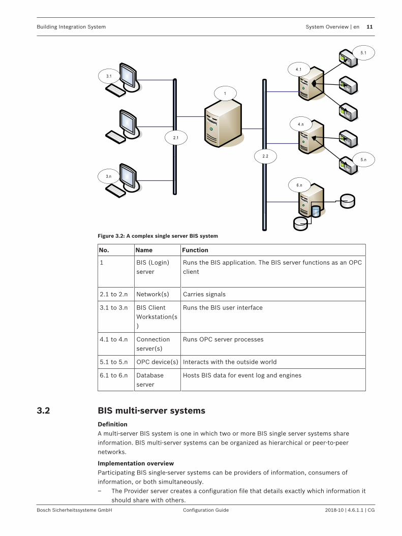
Figure 3.2: A complex single server BIS system
No. Name Function
1 BIS (Login)server
Runs the BIS application. The BIS server functions as an OPCclient
2.1 to 2.n Network(s) Carries signals
3.1 to 3.n BIS ClientWorkstation(s)
Runs the BIS user interface
4.1 to 4.n Connectionserver(s)
Runs OPC server processes
5.1 to 5.n OPC device(s) Interacts with the outside world
6.1 to 6.n Databaseserver
Hosts BIS data for event log and engines
3.2 BIS multi-server systemsDefinitionA multi-server BIS system is one in which two or more BIS single server systems shareinformation. BIS multi-server systems can be organized as hierarchical or peer-to-peernetworks.
Implementation overviewParticipating BIS single-server systems can be providers of information, consumers ofinformation, or both simultaneously.– The Provider server creates a configuration file that details exactly which information it
should share with others.

12 en | System Overview Building Integration System
2018-10 | 4.6.1.1 | CG Configuration Guide Bosch Sicherheitssysteme GmbH
– The Consumer server configures and browses the provider server as a remote OPCserver.
Any or all of the information monitored by the provider can be passed to the consumer orconsumers. Typically the information consists of OPC addresses, state-changes, commandsand alarms.
IllustrationFor simplicity, the following illustrates the interaction of one provider and one consumerserver. The size and complexity of the multi-server BIS system is limited by the network trafficand the capacity of the consumer servers to process incoming data.
1
23fw qrv w er ter t
edr tse r t6se
r t45sdxyscydr t 34aw rt3fw3456w 32q
345w e546aw4aw
eraw er7zn 89o7jo
89zzuo789794as
34tcy4
3
2
5
No. Name Function
1 The provider server A kind of BIS server thatprovides information to otherBIS single server systems
2 The subset of the addresses that theprovider server should share
3 The encrypted configuration file generatedby the provider server
Describes the subset ofinformation that the providerserver should share

Building Integration System System Overview | en 13
Bosch Sicherheitssysteme GmbH Configuration Guide 2018-10 | 4.6.1.1 | CG
No. Name Function
4 An OPC server of type BIS Remote System Acts as an interface betweenthe provider server and theconsumer server. It isconfigured on the consumerserver using the encryptedconfiguration file, and thenbrowsed like any otherconnection server.
5 The consumer server This BIS server receives andprocesses information from itsown devices, and those ofconnected provider servers

14 en | Overview of the Configuration Browser UI Building Integration System
2018-10 | 4.6.1.1 | CG Configuration Guide Bosch Sicherheitssysteme GmbH
4 Overview of the Configuration Browser UI4.1 Basic layout of the Configuration Browser
The various parts of the Configuration Browser user interface are referred to as follows.
Overview of Configuration Browser menus.
Label Description
(1) TheTitle bar contains the name of the application plus windows controls tominimize, maximize and close it.
(2) The Tool bar contains the buttons Apply and Discard, which do not becomeactive until settings have been changed in the Dialog field (3). Before anotherdialog can be opened the changes must be either committed or discarded.
(3) The main Dialog field which changes its layout depending on which dialog isselected in the Dialog bar (6)
(4) The Status bar displays information about the currently loaded configuration.
(5) The lower left section of the BIS Configuration Browser window contains theOutlook bar: a set of tabs, arranged vertically as in Microsoft Outlook, whichcan be opened by single-clicking.
(6) The various dialogs belonging to these tabs are then displayed in the Dialogbar.

Building Integration System Overview of the Configuration Browser UI | en 15
Bosch Sicherheitssysteme GmbH Configuration Guide 2018-10 | 4.6.1.1 | CG
Label Description
A single click on one of these dialogs will bring its contents up in the Dialogfield (3).
(5) & (6) The currently active Outlook tab (5) and its associated dialog (6) are highlightedin color.
4.2 The menu structure of the Configuration BrowserThe table below gives an overview of which activities can be carried out in which menus:
Tab Application/Dialog
Description Notes
Administration License Reads and displays the contentsof a license file.
Serverstructure
Configures and administers rightson the system server.
Information Contains program andconfiguration versions pluscustomer data if applicable.
Authorizations Configures bundles of user-rights, known as Authorizations.These can be assigned to BISoperators in the Operatorsdialog.
Operators Assigns Authorizations to BIS andAccess Engine users.
Active directoryconfiguration
Maps an Active directory serverand active directory groups toBIS Authorizations

16 en | Overview of the Configuration Browser UI Building Integration System
2018-10 | 4.6.1.1 | CG Configuration Guide Bosch Sicherheitssysteme GmbH
Audit trailconfiguration
Starts and stops a protocol of allchanges to the BIS configuration,and manages how its storagespace is used.
Audit trailreporting
Displays and searches the Audittrail.
ACE Userprofiles
Defines user profiles based onjob functions
Special dialogs forAccess Engine.
ACEWorkstationprofiles
Sets up workstation profilesbased job functions and userprofiles
ACEWorkstationrights
Defines dialog views perworkstation
ACEWorkstations
Creates and configures newworkstations for Access Engine
Locations Divisions Creates and edits divisions withinthe access-controlled area.
Tree structure Configures the device hierarchyand assigns of location plans toit.
Detectorplacement
Maps detectors to locations
ACE Areas Configures Areas and parking lots Special dialog forAccess Engine.
Connections ConnectionServers
Topmost node of the serverstructure. OPC servers aredisplayed below their respectiveconnection servers.For example Access Engine is theconnection server for accesscontrol functionality.
Infrastructure Detector types Defines and configures detectortypes
States Configures and assigns detectorstates
ACE PIN Codes Defines PIN code parameters(e.g. retry limit, length)
Special dialogs forAccess Engine.
ACE Cardcoding config.
Defines standard values for carddata
ACE Cardreader
Creates and configures cardreaders

Building Integration System Overview of the Configuration Browser UI | en 17
Bosch Sicherheitssysteme GmbH Configuration Guide 2018-10 | 4.6.1.1 | CG
ACE Carddefinition
Creates and configures card dataencodings
ACE Customfields
Creates and configures additionaldata fields for the ACE dialogPersons.
General Settings Virtual Device Groups multiple detectors to onevirtual device.
Address lists Groups multiple addressestogether into lists so that theycan be controlled together.
Timer Creates time schedules so thatcontrols can be executedautomatically at certain times oncertain days.
Associations Associates messages and state-changes with responses.
Counters Display summaries of devicestates
Logging/Protocol
Event log Collects all system events andprovides a means of finding andfiltering them.
Alarm print Defines printers and print-templates for workstations
Protocol print Defines the contents ofprotocols.
Tools ACE BadgeDesigner
Creates badge layouts for accesscontrol.This program has its own onlinehelp.
Special dialog forAccess Engine.These applicationshave their own online helps.
ACEConfigurationimport/export
Configures import and exportdataThis program has its own onlinehelp.
ACE Systemparametereditor
Displays and Edits systemparameters for access control.
ACEConfigurationCardPersonalization
Configures the badge creationprogram for access control.

18 en | Overview of the Configuration Browser UI Building Integration System
2018-10 | 4.6.1.1 | CG Configuration Guide Bosch Sicherheitssysteme GmbH
ACEConfigurationAMC IPaddresses
Configures IP-Addresses forAMCs [access control data].
VIEConfiguration
Configures the Video Engine. Special dialog forVideo Engine.Described in theVideo Engine helpfile that is linked tothis help file if VIE isinstalled..
Remote siteconfiguration
Creates the encryptedconfiguration files for Providerservers, that is, servers whichmake some or all of theiraddresses visible to Consumerservers
Distributedreportconfiguration
Configures a special event logreport that contains events frommultiple networked BIS servers
4.3 Working with lists and large numbers of dataMany of the dialogs in the Configuration Browser contain lists with potentially high numbers ofelements.
In order to work more effectively with such lists BIS supports, where appropriate, thecommon MS Windows idioms for the selection of list elements.– Single selection
Click once on a list element– Multiple selection...
– ...of contiguous elementsClick once on a list element then click another element in the same list whilstholding the Shift key. Both elements and all intervening elements will be selected.
– ...of discontiguous elementsHold the Crtl key and click to select or deselect multiple discontiguous elements in alist.
– Complete selectionPress Crtl + A within the list
– Activation / Deactivation of list elementsIf list elements contain additional check boxes for activation/deactivation then multipleselection of those check boxes is achieved as follows:– Multiply select the desired list elements as described above– Press the Space bar. This toggles the selection of all the check boxes whose list
elements have been selected.

Building Integration System Overview of the Configuration Browser UI | en 19
Bosch Sicherheitssysteme GmbH Configuration Guide 2018-10 | 4.6.1.1 | CG
4.4 Customizing BIS Configurator Outlook buttons
The standard settings show the Outlook buttonsin the left column of the configuration browser,complete with icon and title.There are two ways to fold these buttons into acompact form (miniature icons) and back:– By mouse.– By button
Fold/Unfold by mouse
Move the mouse to the upper edge of theAdministration button until its cursor changes toa double-headed arrow. Then left-click and dragthe edge downwards.
The visible buttons are removed one-by-one, andthe last button compensates by displaying aminiature icon for each button removed.
Conversely, by pulling the edge upwards, theoutlook buttons reappear and their miniatureicons disappear.
Notice!The currently active outlook button is marked only by a yellow background.Click other icons to activate other functions.
Fold/Unfold by button
Click on the button marked >> on theright hand side of the icon button.

20 en | Overview of the Configuration Browser UI Building Integration System
2018-10 | 4.6.1.1 | CG Configuration Guide Bosch Sicherheitssysteme GmbH
Click Show More Buttons in themenu to replace a miniature iconwith its Outlook button.
Click Show Fewer Buttons in themenu to replace an Outlook buttonits miniature icon.
4.5 Symbols used in the BIS Configuration BrowserThe following symbols are used in the BIS Configuration Browser.
Hardlock
Protocol print Alarm print
Operators Authorizations
Tree structure Information
Event log Detector placements
Divisions Detector types
Time schedules Server structure
States Virtual devices

Building Integration System Overview of the Configuration Browser UI | en 21
Bosch Sicherheitssysteme GmbH Configuration Guide 2018-10 | 4.6.1.1 | CG
Address lists Associations
Device condition counters Administration
Location Logging / Protocol
Connections Infrastructure
Accessories Tools

22 en | General configuration concepts and activities Building Integration System
2018-10 | 4.6.1.1 | CG Configuration Guide Bosch Sicherheitssysteme GmbH
5 General configuration concepts and activitiesThis section gives an overview of configuration concepts, prerequisites and structure. It alsointroduces those activities which are common to all BIS configurations.
Notice!Avoid special charactersUse no special or non-Latin characters in BIS (e.g. Chinese, Russian, ä, é, ô, /, #, %, $, |, !, ~,‘ ). Use only non-diacritic (7-bit ASCII), alphanumeric characters [A-z] [0-9] plus underscore.This applies to any characters typed into the BIS installation wizard or configuration browser,including passwords.
5.1 Overview of BIS configurationBIS is a system which potentially integrates all the monitoring systems of its installation site.In order to do this the system must internalize a model of all the objects to be monitored andcontrolled. The creation of this model is the BIS configuration process. Any number of models,known as configurations, may be created, reflecting refinements or variants, but only oneconfiguration can be loaded into BIS at a time. If a new configuration is loaded, then alloperators are required to restart their clients, either immediately or after a set grace period.– Configurations are stored as mnemonically named directory trees of files below the BIS
server’s main directory MgtS. For more details see Structure and organization of theconfigurations, page 52
– Configurations are edited largely using a tool known as the Configuration Browser (theonly exception being those html files that are displayed in the BIS client application -these are typically edited in WYSIWYG html editors.)
The following illustration and table give an overview of configuration steps.

Building Integration System General configuration concepts and activities | en 23
Bosch Sicherheitssysteme GmbH Configuration Guide 2018-10 | 4.6.1.1 | CG
Figure 5.1: Overview of configuration steps
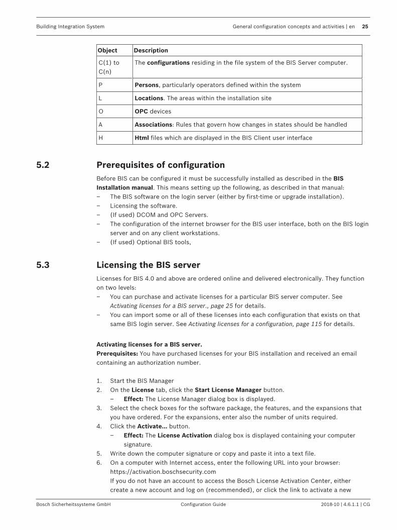
Object Description
BM The BIS Manager application - acts as a dashboard for the BIS server
CB The Configuration Browser application - the editor for BIS configurations
BS The BIS Server application, which runs the configuration in backgroundprocesses, and which can be controlled through the BIS Manager.
C(1) toC(n)
The configurations residing in the file system of the BIS Server computer.Only one configuration is loaded at any one time.
Process Description

24 en | General configuration concepts and activities Building Integration System
2018-10 | 4.6.1.1 | CG Configuration Guide Bosch Sicherheitssysteme GmbH
Object Description
1 The BIS Manager starts the Configuration Browser
2 The Configuration Browser creates and edits configurations
3 The BIS Manager controls the BIS server process: It loads a new, existingtemplate or edited configuration and then starts the BIS server process withthat configuration.
The following illustration and table show the main elements which make up a configuration.For clarity of overview it is not a complete list.
Figure 5.2: Elements of a typical configuration
Building Integration System General configuration concepts and activities | en 25
Bosch Sicherheitssysteme GmbH Configuration Guide 2018-10 | 4.6.1.1 | CG
Object Description
C(1) toC(n)
The configurations residing in the file system of the BIS Server computer.
P Persons, particularly operators defined within the system
L Locations. The areas within the installation site
O OPC devices
A Associations: Rules that govern how changes in states should be handled
H Html files which are displayed in the BIS Client user interface
5.2 Prerequisites of configurationBefore BIS can be configured it must be successfully installed as described in the BISInstallation manual. This means setting up the following, as described in that manual:– The BIS software on the login server (either by first-time or upgrade installation).– Licensing the software.– (If used) DCOM and OPC Servers.– The configuration of the internet browser for the BIS user interface, both on the BIS login
server and on any client workstations.– (If used) Optional BIS tools,
5.3 Licensing the BIS serverLicenses for BIS 4.0 and above are ordered online and delivered electronically. They functionon two levels:– You can purchase and activate licenses for a particular BIS server computer. See
Activating licenses for a BIS server., page 25 for details.– You can import some or all of these licenses into each configuration that exists on that
same BIS login server. See Activating licenses for a configuration, page 115 for details.
Activating licenses for a BIS server.Prerequisites: You have purchased licenses for your BIS installation and received an emailcontaining an authorization number.
1. Start the BIS Manager2. On the License tab, click the Start License Manager button.
– Effect: The License Manager dialog box is displayed.3. Select the check boxes for the software package, the features, and the expansions that
you have ordered. For the expansions, enter also the number of units required.4. Click the Activate… button.
– Effect: The License Activation dialog box is displayed containing your computersignature.
5. Write down the computer signature or copy and paste it into a text file.6. On a computer with Internet access, enter the following URL into your browser:
https://activation.boschsecurity.comIf you do not have an account to access the Bosch License Activation Center, eithercreate a new account and log on (recommended), or click the link to activate a new

26 en | General configuration concepts and activities Building Integration System
2018-10 | 4.6.1.1 | CG Configuration Guide Bosch Sicherheitssysteme GmbH
license without logging on. Note that for SMA (software maintenance agreement) licensesan account is always required. An account has the further advantage of keeping track ofall your activations for future reference.
Follow the instructions on the website to obtain the License Activation Key.
7. Return to the software. In the License Activation dialog box, type or paste in the LicenseActivation Key obtained from the Bosch License Activation Center and click the Activatebutton.– Effect: The software packages are activated for the computer.
8. Click the Refresh button to view the modified set of activated licenses
Notice!Effects of hardware and software changesChanges to the hardware of the BIS login server may invalidate your license and cause BIS tostop functioning. Please check with technical support before making changes to the BIS loginserver.
Import buttonsThe button Import Bundle Info is not currently used in BIS.The button Import License may be used in rare cases to import special license files, forexample from technical support.
Demo Mode for developing and testing new configurations.The BIS Configuration Browser, as opposed to the BIS application, can create and edit anyconfiguration even beyond the scope of your license. Such configurations can be run andtested however only in Demo Mode. See License, page 115 for more information on demomode.
Demo Mode for Access Engine (ACE)Note that, if installed, the BIS Access Engine (ACE) uses its own form of Demo Mode. This canbe activated for ACE configurations in the Configuration Browser by clicking Administration >ACE Licenses > button: Activate Demo Mode.
5.4 Starting and stopping the BIS serverThe BIS server software can be configured so that it is started automatically whenever the BISserver computer is booted.(Click here for additional information: The System Start/Stop tab, page 103)Otherwise the server must be started and stopped manually as described below:Open the BIS Manager and perform the following steps on the System start/-stop tab:
Task and statusinformation
Description

Building Integration System General configuration concepts and activities | en 27
Bosch Sicherheitssysteme GmbH Configuration Guide 2018-10 | 4.6.1.1 | CG
Click “StartServercomponent”Status LED: orange
During the startup process the BIS Manager displays by name thesteps involved (1) and indicates overall progress with a progress bar(2)
For as long the Status LED (3) glows orange the system is waitingfor the execution of program components. Mouse over the LED todisplay the names of components not yet started. To the left of theLED BIS displays the names of the BIS products installed.
Display of the operatorslogged on.Status LED: green
If the startup process completes successfully then the Status LED(3) glows green and the BIS Manager switches to a tabular display ofthe operators logged on (4).
– The display contains the following information:– Operator name– IP address– Online since– Authorization– Activated by– Maximum bandwidth
“Stop” Servercomponent
This is necessary, for example, to carry out a software update on theserver.During the shutdown process BIS displays the steps involved.To stop processing pending data from the OPC servers, and therebyspeed up the shutdown process, click the X button (5).

28 en | General configuration concepts and activities Building Integration System
2018-10 | 4.6.1.1 | CG Configuration Guide Bosch Sicherheitssysteme GmbH
You will need to confirm this decision (6).
After confirming, the cancelled step will be marked with a red X (7).
Stop the system serverStatus LED: red
After a successfully shutting down the server, the Status LED (3) willbe red and all steps carried out normally will be marked with a greentick (8).
The message below the progress bar confirms that the services havebeen stopped, and continues to list the installed BIS products. (9).

Building Integration System General configuration concepts and activities | en 29
Bosch Sicherheitssysteme GmbH Configuration Guide 2018-10 | 4.6.1.1 | CG
Notice!To inform logged-in operators of an impending shutdown of the BIS server, use Transmitmessage tab in the BIS Manager. Whenever the BIS server process is stopped all suchoperators will automatically be logged off.
5.5 Starting and stopping the BIS Configuration Browser
Perform the following procedure to start the BIS Configuration Browser:1. From the BIS Manager's System start/stop tab, click the Start button next to the
Configuration Browser label.

30 en | General configuration concepts and activities Building Integration System
2018-10 | 4.6.1.1 | CG Configuration Guide Bosch Sicherheitssysteme GmbH
2. The initial Configuration Browser window appears.
3. If your configuration already exists it can be selected here. Click the configuration nameto start the Configuration Browser with that configuration. If you are configuring BIS forthe first time, please continue with the next section Setting up an initial BIS configuration,page 30.
4. Once started, the Configuration Browser can be stopped in the Windows fashion byclicking Menu: File > Exit or the Close (“x”) button in the title bar.
Notice!If you load a configuration created with an earlier version of BIS, you may be prompted toupdate the configuration file. This process will not change the configuration contents, onlythe file format.
5.6 Setting up an initial BIS configuration
Perform the following steps to set up a required initial configuration for the BIS server:

Building Integration System General configuration concepts and activities | en 31
Bosch Sicherheitssysteme GmbH Configuration Guide 2018-10 | 4.6.1.1 | CG
1. From the BIS Manager main screen, click Start Configuration program. The initialConfiguration Browser window appears.
32 en | General configuration concepts and activities Building Integration System
2018-10 | 4.6.1.1 | CG Configuration Guide Bosch Sicherheitssysteme GmbH
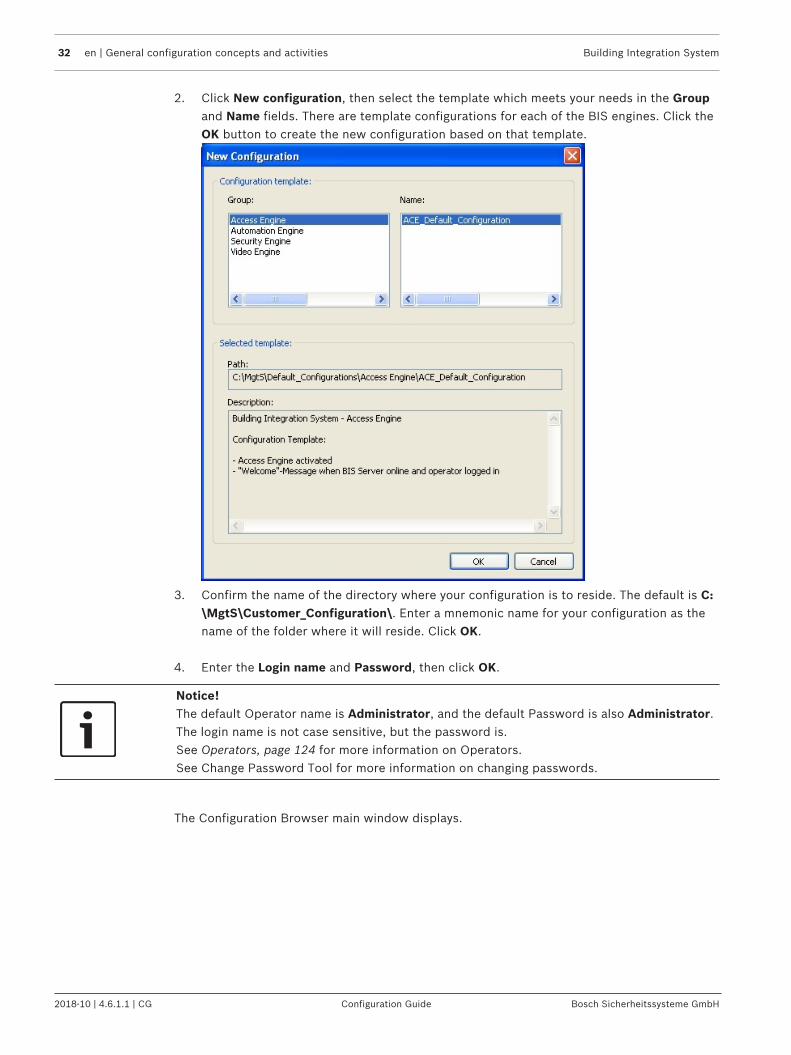
2. Click New configuration, then select the template which meets your needs in the Groupand Name fields. There are template configurations for each of the BIS engines. Click theOK button to create the new configuration based on that template.
3. Confirm the name of the directory where your configuration is to reside. The default is C:\MgtS\Customer_Configuration\. Enter a mnemonic name for your configuration as thename of the folder where it will reside. Click OK.
4. Enter the Login name and Password, then click OK.
Notice!The default Operator name is Administrator, and the default Password is also Administrator.The login name is not case sensitive, but the password is.See Operators, page 124 for more information on Operators.See Change Password Tool for more information on changing passwords.
The Configuration Browser main window displays.

Building Integration System General configuration concepts and activities | en 33
Bosch Sicherheitssysteme GmbH Configuration Guide 2018-10 | 4.6.1.1 | CG
1. Click Administration, then select Server structure. The Server structure screen displays.
2. If the suggested name is not correct, click Modify and edit the Server name field so thatit matches the server's net BIOS Computer Name.
3. If a firewall prevents network name resolution, enter the server's IP address, making surethe server has a static IP address (not DHCP). Otherwise leave the defaultselection ...server name mapping to:
4. Click Apply.5. Close the Configuration Browser window.

34 en | General configuration concepts and activities Building Integration System
2018-10 | 4.6.1.1 | CG Configuration Guide Bosch Sicherheitssysteme GmbH
6. In the BIS Manager window, select the Load/save configuration tab. It contains twopanes: Load new configuration and Save current configuration.
7. In the Load new configuration pane, click the ellipsis button to browse.8. Select the directory containing the configuration to load, then click OK.
9. In the Load new configuration pane, click the Load, button then confirm by clicking Yes.10. Click Close.11. From the System start/stop tab of the BIS Manager main screen you will see the server
start. See Starting and stopping the BIS server, page 26 for more details.

Building Integration System General configuration concepts and activities | en 35
Bosch Sicherheitssysteme GmbH Configuration Guide 2018-10 | 4.6.1.1 | CG
You have now created and loaded a valid initial server configuration. However it does not yetcontain any the functional elements of a working configuration.
5.7 Creating a new configurationTo create a new BIS configuration, follow the procedure outlined in Setting up an initial BISconfiguration, page 30:
5.8 Opening (loading), saving and copying configurations
Opening a configurationIn the BIS Manager click the Start button next to the Configuration Browser label. A dialogappears in which you can create new or open existing configurations:
Loading a named configurationFrom the BIS Manager's Load/save configuration tab, click the “...“ button and navigate to thedesired configuration file, then click the Load button.
How BIS saves and loads configuration data– Changes made to a configuration in the Configuration Browser are saved to the named
directory of that configuration (under <INST_DIR>\Customer_Configuration\ ) every timeyou change from one main menu to another.
– Whenever you click the Start or Load button in the BIS Manager BIS compares the namedconfiguration it last used with the configuration in <INST_DIR>\Runtime_Config\. It thencopies any modified files to <INST_DIR>\Runtime_Config\ and then loads thatconfiguration.
– To run a different named configuration from the one loaded last time, click BIS Managertab: Load/save configuration , enter or browse the location of the desired configurationin the Configuration text field and click button: Load.
– To save the current configuration for later use or modification, click BIS Manager tab:Load/save configuration , enter or browse the desired location in the Save as text fieldand click button: Save.
Notice!Saving configuration data from non-Bosch OPC servers and remote computersConfiguration data of non-Bosch OPC servers and connection servers on other computersmust be backed up separately when saving the configuration.

36 en | General configuration concepts and activities Building Integration System
2018-10 | 4.6.1.1 | CG Configuration Guide Bosch Sicherheitssysteme GmbH
Reloading a modified running configurationIf the running configuration is changed by an administrator it must be reloaded for thechanges to take effect. There are two options:– Reload the configuration with immediate effect, disconnecting all operators at once.
Note: this was the default behavior up to and including BIS Version 3.0.– Reload the configuration with delayed effect (10 minutes by default). This allows the
operators a grace period in which to finish what they are doing and restart their clientsmanually.Note: a major benefit of this option is that, in the case of two or more operators, at leastone operator may be logged on at all times. That is, there is no longer any time in whichthe BIS Messages are not being monitored.
Figure 5.3:
Reloading a modified configuration with immediate effectThis option is recommended where it is not imperative that at least one operator be logged onto BIS at all times. It is also recommended whenever changes have been made to operatorauthorizations.Prerequisite: You are on the BIS Manager tab: Load/save configuration1. Click button: Load
Building Integration System General configuration concepts and activities | en 37
Bosch Sicherheitssysteme GmbH Configuration Guide 2018-10 | 4.6.1.1 | CG
Result: The Load new configuration dialog appears2. Select the radio button Log off all users immediately3. Click button: OKP Result: The configuration is reloaded immediately, the clients are restarted and their
operators left at the BIS login prompt.
Reloading a modified configuration with delayed effectThis option is recommended where it is imperative that at least one operator be logged on toBIS at all times. However if changes have been made to operator authorizations then animmediate logoff is recommended instead.Prerequisite: You are on the BIS Manager tab: Load/save configuration1. Click button: Load
Result: The Load new configuration dialog appears2. Select the radio button Allow users to postpone logoff for a further ____ minute(s).3. Set a new value for the number of minutes, or leave the default in the text box.4. Click button: OKP Result: All operators on connected clients are shown a dialog box inviting them to restart
their clients as soon as possible, but displaying a timer counting down from number ofminutes set above. When the timer reaches zero the configuration is reloadedimmediately, the clients are restarted and their operators automatically logged on again.
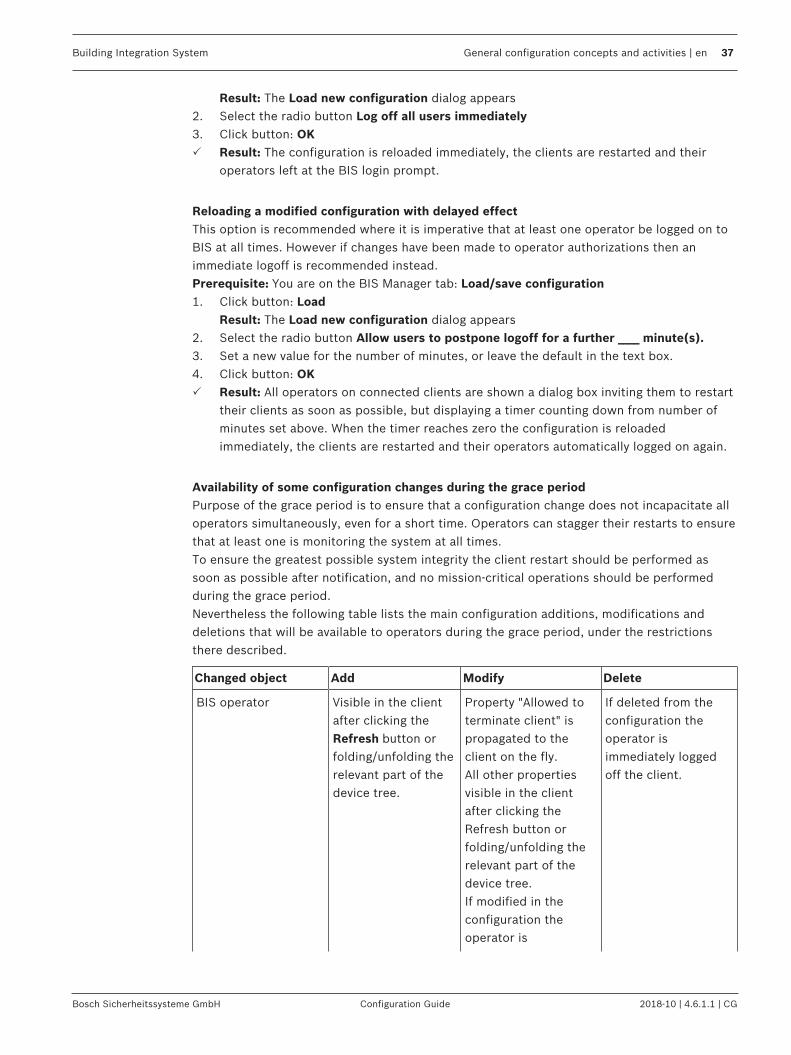
Availability of some configuration changes during the grace periodPurpose of the grace period is to ensure that a configuration change does not incapacitate alloperators simultaneously, even for a short time. Operators can stagger their restarts to ensurethat at least one is monitoring the system at all times.To ensure the greatest possible system integrity the client restart should be performed assoon as possible after notification, and no mission-critical operations should be performedduring the grace period.Nevertheless the following table lists the main configuration additions, modifications anddeletions that will be available to operators during the grace period, under the restrictionsthere described.
Changed object Add Modify Delete
BIS operator Visible in the clientafter clicking theRefresh button orfolding/unfolding therelevant part of thedevice tree.
Property "Allowed toterminate client" ispropagated to theclient on the fly.All other propertiesvisible in the clientafter clicking theRefresh button orfolding/unfolding therelevant part of thedevice tree.If modified in theconfiguration theoperator is
If deleted from theconfiguration theoperator isimmediately loggedoff the client.

38 en | General configuration concepts and activities Building Integration System
2018-10 | 4.6.1.1 | CG Configuration Guide Bosch Sicherheitssysteme GmbH
Changed object Add Modify Delete
immediately logged offwithout reloading theconfiguration.
Device / Groups /Detectors and otherBIS addresses
Visible in the clientafter clicking theRefresh button orfolding/unfolding therelevant part of thedevice tree.
Changes of addressare visible in the clientafter clicking theRefresh button orfolding/unfolding therelevant part of thedevice tree.A client restart isrequired to displaychanged namesreliably.
A client restart isrequired to removedeleted devices fromthe GUI.Until restart thedeleted objects aremarked with a #character.
Address lists Visible in the clientafter clicking theRefresh button orfolding/unfolding therelevant part of thedevice tree.
Changes of addressare available.Note: Change ofaddress list namerequires client restart
Until restart thedeleted objects aremarked with a #character.
Graphic files / Namedviews / Layers
Detector mappingsavailable.State changes arehighlighted with thecolors of the newstates.
Not available.The old graphic fileand layer informationare not updated untilafter client restart
Not available.The old graphic fileand layer informationare not updated untilafter client restart
Action plan and Misc.documents
Newly created linksto Action Plans andMisc. Documents areavailable.
If an Action Plan orMisc. Document is inuse when its link ischanged or deleted,then the old documentpersists until theoperator has finishedin it.The newly linkeddocument will notappear until the nextinvocation.
If an Action Plan orMisc. Document is inuse when its link ischanged or deleted,then the olddocument persistsuntil the operator hasfinished in it.A document that hasbeen unlinked will notappear again.
Timer settingsNB: General settings>Timer (not the timerwithin jobs)
Available Available Available

Building Integration System General configuration concepts and activities | en 39
Bosch Sicherheitssysteme GmbH Configuration Guide 2018-10 | 4.6.1.1 | CG
Changed object Add Modify Delete
Counters and groups Not available Changes inparticipating addresslists and state listsavailable.Changes in name and/or color requirerestart.
Counter remainsvisible but ceases tocount
Associations (Jobs) Available Available Available
BIS operatorauthorizations
(not directly visiblein the client)
The followingmodificationsavailable:– The property
"Allowed toterminate client"
– Modifications toaddresses andaddress lists
Authorization can onlybe deleted if nooperator has it.
ACE user profiles Available Available Available
ACE workstationprofiles
Available Available Available
ACE areas Available uponRefresh
Available uponRefresh
Available uponRefresh
ACE reader types,card configurations,PIN codeconfigurations
Available Available Available
ACE divisions Requires clientrestart
Requires client restart Requires client restart
Index page Requires clientrestart
Requires client restart Requires client restart
Virtual devices Available Requires client restart Requires client restart
Alarm print Print template, statemapping, printer andlayer information isupdated forautomatic alarmprinting.All other featuresrequire client restart
Print template, statemapping, printer andlayer information isupdated for automaticalarm printing.Modified layerinformation is notavailable for manualprinting.
Print template, statemapping, printer andlayer information isupdated forautomatic alarmprinting.All other featuresrequire client restart
Event log Available Available Available

40 en | General configuration concepts and activities Building Integration System
2018-10 | 4.6.1.1 | CG Configuration Guide Bosch Sicherheitssysteme GmbH
Changed object Add Modify Delete
OPC and connectionservers
Available uponRefresh
Requires client restart Requires client restart
Copying a configurationWhen you save a configuration under a new name (in the configuration client, select Load/save configuration, then click Save As...), all configuration files are saved in a new directory.This allows you to create variants of a configuration without changing the originalconfiguration.
Saving your configuration work
Notice!Recommended practiceAll modifications made in the Configuration Browser are saved when you select the Load/save configuration tab, then click Save. Remember to save your configuration work periodically.
5.9 Configuration printoutsTo print a summary of the entire configuration click menu: File > Print in the ConfigurationBrowser.
5.10 System operatorsIntroductionThere are two kinds of system operators:– System-defined operators such as BIS, Administrator.– User-defined operators,
whereby user-defined operators can be either:– BIS operators defined only within BIS
or– BIS operators based on Active Directory users.
The following sections describe how to set up both kinds of user-defined operators in thesystem.
Special predefined authorizationsAll user-defined operators require an Authorization, which is a set of permissions to access,to control and to modify parts of the system.– The authorization No authorization is automatically assigned to every newly created
operator. This means that all operators are initially disabled by default. You must alwaysassign a different authorization manually to enable the new operator to log on to thesystem.
– The authorization Administrator, which has all permissions, always exists, and can beused initially to set up any operator. For security reasons Bosch urgently recommendsthat you create and assign a less powerful authorization to new operators.
Note that the predefined authorization Operator ACE only exists if Access Engine is installedand licensed.

Building Integration System General configuration concepts and activities | en 41
Bosch Sicherheitssysteme GmbH Configuration Guide 2018-10 | 4.6.1.1 | CG
PrerequisitesAuthorizationsIf the new operator is to have less than total Administrator control of the system, then createa restricted authorization for them.For instructions on creating a new customized authorization see section Authorizations, page118ProfilesThe new operator will also require a User profile, which determines the layout and screenresolution of their BIS logon screen.For instructions on creating a new customized User profile see section Operators, page 124WorkstationsSecurity-critical operator tasks will need to be performed on workstations in secure areas.Less critical tasks may be performed, for example, on workstations at the reception desk.BIS provides different ways of mapping operators’ authorizations to workstations:– Apply to all workstations: An operator’s authorization can be used at all workstations
without restriction.– IP-filtered: An operator’s authorization can only be performed at a workstation with a
particular IP address, or at an address within a specified subnet. Note only IP version 4 is currently supported.
– Workstation specific: An operator’s authorization can be assigned to one or moreworkstations selected from the list of all configured workstations.
For instructions on the different mappings, see the following sections.
Notice!Operator names are limited to 50 characters.The following characters are not allowed: # < > ' " & * ? .The password is case sensitive but the name itself is not.
See also– Authorizations, page 118
5.10.1 Operators with authorizations on all or on IP-filtered workstationsProcedure1. In the Configuration Browser, navigate to Administration > Operators
The main Operators dialog appears
2. Click the icon to add a new Operator to the list, or to edit an existing Operator.Adhere to naming restrictions above.
3. From the list labeled Authorization: select a suitable authorization for the operator. SeePrerequisites above.
4. From the list labeled Use profile: select a suitable operator profile. See Prerequisitesabove.
5. Ensure that the check box Apply to all workstations is selected (default)6. (Optional) If the new operator is to work only from a particular workstation, enter the IP
address of the workstation in the text box IP address.7. (Optional) If the new operator is to work only from a particular subnet, enter an IP filter
additionally in the text box IP filter. For instructions on creating an IP filter see Operators,page 124
8. Click Apply to save the changes.

42 en | General configuration concepts and activities Building Integration System
2018-10 | 4.6.1.1 | CG Configuration Guide Bosch Sicherheitssysteme GmbH
See also– Operators, page 124
5.10.2 Operators with authorizations on selected workstationsPrerequisitesYou are logged on to the BIS configuration browser as a normal BIS operator, not as an ActiveDirectory user.Procedure1. In the Configuration Browser, navigate to Administration > Operators
The main Operators dialog appears
2. Click the icon to add a new Operator to the list, or to edit an existing Operator.Adhere to naming restrictions above.
3. From the list labeled Authorization: select a suitable Authorization for the operator. SeePrerequisites above.
4. From the list labeled Use profile: select a suitable operator profile. See Prerequisitesabove.
5. Ensure that the check box Apply to all workstations is cleared.– The Workstation specific authorization pane appears with 2 columns: Workstation
and Authorization.– All the workstations that are defined within the current configuration are listed in the
pane.– If an authorization was already in the Authorization pull-down list when you cleared
the Apply to all workstations check box, then that authorization is copied to theAuthorization column for all workstations.
6. To set an authorization for a particular workstation, click in the Authorization column andselect one of the defined authorizations from the cell’s pull-down list.Repeat this step for all workstations in the list.
7. Alternatively, to copy the same assignment to all the other workstations listed, click the button at the end of the row.
8. Click the Apply button to save the changes.

Building Integration System General configuration concepts and activities | en 43
Bosch Sicherheitssysteme GmbH Configuration Guide 2018-10 | 4.6.1.1 | CG
Additional remarks on mapping authorizations to selected workstationsThis method of mapping is completely explicit, without exceptions. It follows that:Operators whose authorizations are workstation specific can only log on to workstations thatare explicitly defined, and for which they have a non-void authorization (i.e. not Noauthorization).Hence, if such operators need to log on to the BIS server, then the BIS server must beexplicitly defined as a workstation in the configuration.
Saving and reloading authorization / workstation mappings.– Click Save as… to save the current authorization / workstation mapping to the BIS
configuration. Give it a mnemonic name.– Click Load… to load a saved mapping by name, and so apply it to a different operator if
desired.
Conflict resolution where workstations are multiply definedThe same workstation may be defined twice in the list, namely by:1. IP address2. Hostname
The BIS server itself may be defined as many as 4 times, namely by:1. Local IP address (127.0.0.1)
2. localhost
3. IP address4. Hostname
In such cases, when searching for an authorization for an operator, the system searches theworkstation definitions in the order 1..2 or 1..4 as stated above, and assigns the authorizationthat is mapped to the first workstation definition that it finds.

44 en | General configuration concepts and activities Building Integration System
2018-10 | 4.6.1.1 | CG Configuration Guide Bosch Sicherheitssysteme GmbH
Passwords for operators that are set up in BISWhen a new operator is set up its password is the same as the operator name.The operators themselves can change their passwords when logging on to the BIS client. Forsecurity reasons it is important to change the default password as soon as possible.An operator with sufficient authorization can set or reset an operator password in theConfiguration Browser.1. In the Configuration Browser main window menu, click: Extras > Change password…2. Enter the operator user name, old password, new password (twice).
5.10.3 Setting up an Active Directory user as an operatorPrerequisitesAn Active Directory server is available on your network, and the usernames of potentialoperators are registered on it.
Procedure1. In the Configuration Browser, navigate to Administration > Active Directory config2. Next to the text field Server Information: click the Modify… button
The dialog Active Directory server information appears3. Enter values for the following parameters:
– Server name: The name or IP address of the active directory server on your network– Protocol: Use the default LDAP
– Port: Use the default 389
– Proxy user name: The username of an account with administrator privileges on theActive Directory server
– Proxy user password: the password for that account.4. Click the button Test connection to test the connection to the Active Directory server
Ensure that the connectivity is confirmed on the button before proceeding. In the case offailure, revise the server information in the dialog.
5. Click the OK buttonThe dialog Active Directory server information closes
6. Back on the main dialog Active Directory config click the Modify filter groups… buttonThe dialog Active Directory group filter appears
7. Click the button List groupsThe Active Directory groups are listed in the list window.
8. Click OKThe dialog Active Directory group filter closes
9. Back on the main dialog Active Directory config click the list Active Directory groupsand select an Active Directory group from which to add a BIS operator.
10. Click the list BIS authorization and select a BIS Authorization to be associated with thatActive Directory group
11. Click the list BIS user profile and select a BIS user profile to be associated with theActive Directory group and BIS authorization
12. Click the Add buttonA mapping between an Active Directory group and the BIS Authorization appears in thelist labeled Existing mappings:
13. Repeat the steps 6 to 12 above to create more mappings.14. To delete or change the order of mappings in the list, select lines in the list and use the
buttons (move up, move down, delete) next to the list.

Building Integration System General configuration concepts and activities | en 45
Bosch Sicherheitssysteme GmbH Configuration Guide 2018-10 | 4.6.1.1 | CG
Notice!Note that when assigning an Active Directory user to a BIS Authorization, the system readsthis list from top to bottom, and assigns the BIS Authorization that is mapped to the firstActive Directory group to which that user belongs.
Communicating Active Directory changes to BISIf Active Directory groups are subsequently renamed or deleted you must communicate thesechanges to BIS. Proceed as follows:1. In the Configuration Browser, navigate to Administration > Active Directory config2. Click the Sync groups button3. Respond with OK to any ensuing warnings about deletions or renamings.
The changes will be reflected in the Existing mappings list.
Notice!Active Directory users whose groups are no longer mapped to BIS Authorizations will nolonger be able to log into BIS.
Instructing an Active Directory user to log on to the systemWhen you have created a mapping between an Active Directory group and a BIS Authorization,any member of that group can log on to BIS, and work with that BIS Authorization. Instruct thenew user as per the following example.If the Active Directory domain is called MYDOMAIN and the username Miller then the user logs
on to the system with:– Username: MYDOMAIN\Miller (note the backslash between domain and username)
– Password: <Active Directory domain password for MYDOMAIN\Miller>
5.11 OPC classic connectionsIntroductionOPC servers are the means by which BIS interacts with the outside world. As a BISconfigurator you should already have a good understanding of OPC technology. BIS workswith different kinds of OPC server:– AE (Access Event): Green icons.– DA (Data Access): Blue icons.– AEDA (Combined Access Event / Data Access): Pink icons.– UA (Unified Architecture). BIS 4.6 and later. See specialized chapter OPC UA connections,
page 48
Adding a classic OPC connectionTo add a new OPC classic connection, follow the procedure described in Creating connectionsand addresses by browsing, page 136.
DA GroupsDA servers (DA or AEDA types) must have at least one Group. DA Groups can be edited in thelower right pane when the respective root node is selected in the BIS-address tree (upperright pane).

46 en | General configuration concepts and activities Building Integration System
2018-10 | 4.6.1.1 | CG Configuration Guide Bosch Sicherheitssysteme GmbH
– The Default group always exists– Add a new group with the + button– Selected DA items can be assigned to any existing DA Group– When a group is deleted, all items in this group become members of the Default group– The text box shows all addresses assigned to a DA Group(For more information on Update Rate and Dead Band, refer to the OPC DA specification.)
Detector Types for non Common Requirements OPC serverEvery BIS address must receive a detector type. “Common Requirements” detectors receivetheir detector types from the OPC server at run-time.
For other OPC servers, the detector types are defined according to the following rules:– AE or combination (AEDA) server: the detector type becomes “R_Event“– DA: The detector type has the form <AccessRights>_<OPC-Type> where–
– <AccessRights> can be on of:R (Readable),W (Writable), RW (Readable andWritable), or XX (unknown)
– <OPC-Type> is the OPC item type
Detector types listed according to their respective BIS engines.The following table lists the common detector types according to the BIS engines where theymay be used. The abbreviations for the BIS engines are as follows:– ACE - Access Engine– AUE - Automation Engine– SEE - Security Engine– VIE - Video Engine
Icon Name Engine
Access Engine ACE
Allegiant Matrix AUE, VIE

Building Integration System General configuration concepts and activities | en 47
Bosch Sicherheitssysteme GmbH Configuration Guide 2018-10 | 4.6.1.1 | CG
AMC2-IO-NET AUE
Application Launcher ACE, AUE, SEE, VIE
Beckhoff (serial) AUE
D6600 Receiver AUE, SEE
Dibos DVR VIE
Divar DVR VIE
FAT AUE, SEE
G-Series Panels SEE
Generic OPC server(Third party)
AUE
LSN / Trend DA AUE
OPC Adapter AUE
Praesidio PA AUE
Printer SNMP ACE, AUE, SEE, VIE
PS-MANSYS /Alphadesk
AUE
VDS AUE
VideoJet IP Video(VCS)
VIE

48 en | General configuration concepts and activities Building Integration System
2018-10 | 4.6.1.1 | CG Configuration Guide Bosch Sicherheitssysteme GmbH
5.12 OPC UA connectionsPurposeThis module describes how to add an OPC UA server to your BIS configuration, and browsethe items that you wish to monitor in BIS.
IntroductionDefinition: OPC Unified Architecture (OPC UA) is an enhanced OPC protocol from the OPCFoundation. It provides better platform independence, scalability and data security than itspredecessors.
Products concernedBuilding Integration System (BIS) 4.6 and later
Intended audienceSystem administrator
ContextConfiguration
5.12.1 Adding an OPC UA server using the Local Discovery ServerPrerequisites– BIS has been successfully installed.– Your BIS system has access to at least one OPC-UA server on the network.– The Windows service OPC UA Local Discovery Server is running on your BIS login server.If the Local Discovery Server is not running then start the service in the Windows Servicesapplication, or proceed to the section Adding an OPC UA server manually (without the LocalDiscovery Server), page 48
Procedure1. In the BIS Configuration Browser navigate to Connections > Connection servers2. Right-click the connection server that is to connect to the OPC UA server and select Add
subsystem…The Select new subsystem dialog opens.
3. From the list labeled Configurable OPC Servers click OPC UA Servers > Generic OPC UAServerThe main pane of the dialog is populated with controls.
4. Ensure that the Local Discovery Server is running (see Prerequisites above): the light bulbicon labeled Local Discovery Server must be appear lit (yellow) and the subsystems thatit has detected are displayed in a list in the center of the dialog.Selecting any server from the list will display its subsystem name, subsystem type andURL in their respective text fields.
5. Select the desired OPC UA server and click the OK button.The selected subsystem is added below the connection server that you selected above.
See also– Adding an OPC UA server manually (without the Local Discovery Server), page 48
5.12.2 Adding an OPC UA server manually (without the Local Discovery Server)Prerequisites– BIS has been successfully installed.
Building Integration System General configuration concepts and activities | en 49
Bosch Sicherheitssysteme GmbH Configuration Guide 2018-10 | 4.6.1.1 | CG
– Your BIS system has access to at least one OPC-UA server on the network.
Procedure1. In the BIS Configuration Browser navigate to Connections > Connection servers2. Right-click the connection server that is to connect to the OPC UA server and select Add
subsystem…The Select new subsystem dialog opens.
3. From the list labeled Configurable OPC Servers click OPC UA Servers > Generic OPC UAServerThe main pane of the dialog is populated with controls.
4. In the text box labeled Server url: Enter the URL of the OPC UA server, without thesecurity mode and security policy, for example opc.tcp://<nodename>:<portnumber>
5. Click the Validate and Add button, with its check mark, to the right of the text box.If the URL is valid, the corresponding OPC UA server will be displayed in the list in thecenter of the dialog. Select that server in the list to display its subsystem name,subsystem type and URL in their respective text fields.
6. Select the desired OPC UA server and click OK.The selected subsystem is added below the connection server that you selected above.
5.12.3 Browsing OPC UA items into the BIS configurationIntroductionWhen an OPC UA server has been added you need to specify which of its items should beincluded in the BIS configuration for monitoring in the BIS application. The enhanced security options offered by OPC UA need to be configured before the individualitems can be browsed. Unlike classic OPC servers, with OPC UA it is not possible to browsethe items by clicking the Connect button immediately.
CertificatesCertificates are an important means of authentication between the OPC UA client (BIS) andthe OPC UA server.The certificates that are automatically created by BIS are stored on the installation drive under\MgtS\pki\own\certs\ . Copy these certificates manually to the standard location for
certificates on the OPC UA server, for example <OPC UA server certificate folder>\pki
\trusted\certs\
BIS will prompt for OPC UA server certificates while validating or connecting. If BIS accepts acertificate then it will be stored under MgtS\pki\trusted\certs\
Notice!No automatic backup of certificatesBIS’s own certificates, and the certificates it has accepted, are not backed up automatically.Back them up manually in order to restore and reuse the configuration.
Procedure1. In the BIS Configuration Browser navigate to Connections > Connection servers2. Right-click the OPC UA subsystem that you wish to browse and select Properties…
The Subsystem properties dialog opens

50 en | General configuration concepts and activities Building Integration System
2018-10 | 4.6.1.1 | CG Configuration Guide Bosch Sicherheitssysteme GmbH
3. In the Endpoint selection drop-down list, select one of the options, depending on yoursecurity requirements and the capabilities of the OPC UA server itself.Depending on the Endpoint selection, the fields Endpoint URL, Security Mode, SecurityPolicy and Message Encoding will be populated.
Endpoint Securitymode
Securitypolicy
Messageencoding
Notes
opc.tcp
SignAndEncrypt
Basic128RSA15
uatcp-uasc-
uabinary
SignAndEncrypt
Basic128RSA15
Binary opc.tcp is the preferred option for
performance. All messages are transferred in binaryformat via TCP protocol.Sign and encrypt is the preferred optionfor security.All the messages are signed andencrypted using security policyBasic128RSA15
opc.tcp Sign -
Basic 256
uatcp-uasc-
uabinary
Sign BasicSha256
Binary All messages are signed but notencrypted, The security policy isBasic256.
opc.tcp None-
None
uatcp-uasc-
uabinary
None None Binary No additional security is applied to themessages transferred.
https None
None
https uabinary
None None Binary If using https, ensure that the TLSencryption used is the same at bothendpoints. See Internet Explorer > Settings >Internet options > Advanced tab >Security
Note that HTTP is deprecated by theOPC UA foundation and is not supportedby BIS.
4. In the Authentication Settings pane > User identity drop-down list, select one of thefollowing options:– Anonymous - The client has no user name or password– User Name and Password (on the computer where the OPC UA server is running).– Certificate - a Browse button appears to enable you to pick a certificate file from
your filesystem, and a text box in which to enter the certificate’s password.5. To verify that the credentials are correct before saving the subsystem properties, click the
Validate Connection button.6. Click OK to save the subsystem properties.
The dialog closes and you are returned to the Configuration browser main window.7. With the desired OPC UA server selected, in the OPC server (available elements) pane,
click the Connect button.The OPC UA server appears in the left pane.

Building Integration System General configuration concepts and activities | en 51
Bosch Sicherheitssysteme GmbH Configuration Guide 2018-10 | 4.6.1.1 | CG
8. Select the OPC UA server in the left pane and expand the tree and locate the items thatyou wish to monitor.
9. Right-click each and select Add node10. Click the Disconnect button.11. Click the Apply button to save your changes to the configuration.
5.13 Exporting detector dataDetector data can be exported for further processing in a format (.CSV) editable in MS Excel
1. In the File menu of the Configuration Browser select Export Detector Configuration... .2. A windows dialog window opens for specifying the target directory for the export.
– The default directory is <Installation drive>:\MgtS\Export\Customer_Configuration\<Name of the configuration directory> and the default filename isAddressExport.csv .
– Change the path and filename if desired– Confirm your input with OK.
3. Answer the question dialog, whether you wish to write a header line containing columnnames to the file
4. The progress bar shows the number of exported detectors and the total number.
The Export contains the following data columns:– Location– Address– Detector type– Description
Notice!Message pool, event log, protocol print, server, timers, operators and application launcheritems are NOT exported.
The resulting file can be edited by columns in MS Excel or as a text file in a normal text editor.
Notice!It is not possible to import detector data.
5.14 Diagnostic tools and event simulationBIS offers several diagnostic tools and methods. In addition to reviewing the error and eventlogs (see BIS Manager tabs, page 103), the following functions are available:– Simulated alarms, page 51– Operator alarms, page 52
Simulated alarmsSimulated alarms are useful for testing the Associations (If-Then rules) in a BIS configuration,to test the display of message documents, or to train operators in message processing. Thesimulated alarm command in fact simulates only a state. Whether a simulated alarm is in factgenerated depends on whether an Association exists that is triggered by the simulated state.For more details please consult the BIS Operation online help.

52 en | General configuration concepts and activities Building Integration System
2018-10 | 4.6.1.1 | CG Configuration Guide Bosch Sicherheitssysteme GmbH
Operator alarmsAn operator alarm is an alarm that is triggered manually by the operator in response toexternal information (e.g. a threat by telephone, or something the operator witnessespersonally), and not automatically detected through a subsystem. For more details pleaseconsult the BIS Operation online help.
5.15 Structure and organization of the configurationsAll files are installed in an installation directory (<INST DIR>). The default installation directoryis C:\MgtS.
Runtime configuration
Directory Description
<INST DIR>\Runtime_Config The directory containing the currently loadedconfiguration. The contents of this directory changewhen the system loads a different configuration.NOTICE!Do not change the data in this directory. Yourchanges will be overwritten the next time thesystem is started or the configuration changed.
Configuration location
Directory Description
<INST DIR>\Customer_Configuration\* After creating a configuration, the configurationdata is saved in a separate sub-directory, which iscreated when the new configuration is made. Thesub-directory can be given any name. The locationof this sub-directory is <INST_DIR>\Customer_Configuration\*.NOTICE!When entering the path, remember that the pathname is case-sensitive.
Configuration contentEvery configuration includes the following content:
File/Directory Description
Configuration.crp The configuration file. This file is stored in the rootdirectory of the configuration. It is automaticallyencoded after every save, then decoded every timeit is opened.
...\Documents This directory contains the start pages. There areseveral sub-directories for location plans, detectoricons, help documents, templates for action plans,event log displays, and the alarm printouts.
...\Documents\Action plans This directory contains the action plan templates.
...\Documents\Floor plans This directory contains the floor plans.

Building Integration System General configuration concepts and activities | en 53
Bosch Sicherheitssysteme GmbH Configuration Guide 2018-10 | 4.6.1.1 | CG
<INST DIR>\LogbookDB This directory contains the files for displaying theevent log content.
...\Documents\MessageDetails This directory contains the documents fordisplaying the messages in the message detailcontrol:MessageDetails.htm: This document displays themessage details for the selected message.EmptyDetails.htm: This document is displayedwhen no message is selected.
...\Documents\Misc This directory contains the miscellaneousdocument templates.
...\Documents\Printouts This directory contains the printout templates.
...\Documents\Symbols This directory contains the detector symbols fordisplaying in floor plans.

54 en | OPC: BIS Connector Building Integration System
2018-10 | 4.6.1.1 | CG Configuration Guide Bosch Sicherheitssysteme GmbH
6 OPC: BIS Connector6.1 Introduction and overview
The OPC Connector is a tool to facilitate the integration of any 3rd-party OPC server into BIS.It can perform arbitrary alphanumeric transformations of item values, and arbitrary topologicaltransformations of namespace hierarchies. Thus it can make any Data-Access (DA) OPC servercompatible with BIS, even those that use, for example, very deep namespaces, long nodenames or non-numerical leaf values.The OPC Connector is bi-directional, enabling BIS both to read values from, and givecommands to, the 3rd-party device.
AssumptionsAs the goal is the connection of a BIS installation with a 3rd-party OPC Server this documentassumes that both have already been installed on their respective computers.Installers are assumed to have a basic knowledge of OPC and enough knowledge of XML thatthey can edit an XML file without invalidating its structure.
Scope of this document– Functionality overview– Installation and configuration of OPC-Connector– Invocation from BIS
Functionality overviewThe OPC Connector makes incompatible OPC servers BIS-compatible, even if the namespacesare very deep, the nodes have very long names or the leaves have non-numerical values. Itfunctions as an intermediary or “wrapper” for the incompatible server: BIS sees only the OPCConnector, and the OPC-Connector translates for BIS all communication, read and write, withthe incompatible server.The OPC Connector also augments BIS functionality: it can read, analyze or resolve stringvalues and bit vectors from otherwise incompatible OPC servers; it can parse these and createmultiple item values from one. Conversely it can combine multiple item values on the OPCserver into one numerical value for BIS.The following graphic illustrates the overall architecture of a BIS installation with OPCConnector. Although illustrated separately here, the three main elements (1), (3) and (5) mayall be installed on a single computer, if required.
Figure 6.1: OPC Connector overview
1 The BIS server 4 DA(*) communication with 3rd-partyOPC server

Building Integration System OPC: BIS Connector | en 55
Bosch Sicherheitssysteme GmbH Configuration Guide 2018-10 | 4.6.1.1 | CG
2 Combined DA/AE(*) communication asper the OPC common requirementsspecification
5 3rd-party OPC server with devices.
(*)DA = “Data Access”AE = “Alarms and Events”
3 OPC Connector.– S = OPC server part– T = Transformer - a DLL (library of
executable code) that performsthe required transformations
– C = OPC Client part
6.2 Installation and configurationOPC Connector is installed as an option within the main BIS installation. It requires noseparate installation.The first step in configuration is to analyze the namespace and the leaf node values of the 3rd-party OPC. Ascertain:– which branches of the namespace can be ignored?– where in the namespace the information is that interests you? What are the paths to this
information?– in what form(s) are the data in the leaf nodes that interest you? decimal numbers? binary
numbers (bit fields)?, alphanumeric strings?– If strings or binary numbers, how should they be transformed in order to render
them as decimal numbers for processing by BIS?– If decimal numbers, it may be that no transformation of leaf values is required. Note:
in this case the editing of the TransformationTypes.xml file described below will
not be required.
The second step is to edit the XML configuration files to the requirements of your 3rd-partyOPC server. Two files are provided, and these contain code examples that cover all thecommonest use-cases.– OPCConnector.xml
– TransformationTypes.xml
The example code works with an example OPC Server DemoOpcServer that is also installed if
the OPC Connector option is chosen during the BIS installation. For more details on startingthe demo OPC server, see the final section of the OPC: BIS Connector chapter.
6.2.1 TransformationTypes.xmlThis XML file is required if leaf values need to be transformed into decimal values for use byBIS. It contains XML descriptions of all the transformation types that the OPC Connectorneeds to perform. The Name attribute provides the link back to the <Transformations>
section in OPCConnector.xml.
Currently 3 types of transformation are available:– NodeToLeaf type, that is either
– BitFieldToLeaf or– RegExToLeaf
– LeafToNodeDetails on these transformation types are provided in the following sections.

56 en | OPC: BIS Connector Building Integration System
2018-10 | 4.6.1.1 | CG Configuration Guide Bosch Sicherheitssysteme GmbH
Transformation type BitFieldToLeaf:The OPC Connector converts a decimal number to a binary and then parses it to providevalues for leaves in the BIS namespace. For instance, a decimal value of 11 is converted to abit field of [1011], which in turn is interpreted to mean that the battery is on-line (1), the fuellevel is not OK (0), the motor is on (1) and oil level is OK (1).The first attributes of the description are– Name of the transformation. The Name attribute is crucial, as it is referenced by the other
XML file, OPCConnector.xml
– ActivationState : the default numerical state for the BIS leaf node associated with any
bit in the bit field if that bit gets set to 1, either by a BIS Command (e.g. Set Value) or bythe OPC server.
– DeactivationState : the default numerical state for the BIS leaf node associated with
any bit in the bit field if that bit gets set to 0, either by a BIS Command (e.g. Set Value) orby the OPC server.
Note that these default states will be overridden by any ActivationState or
DectivationState present in the <Transformation> elements of individual bits (see
below).Thus the first lines of the BitFieldToLeafTransformation element might look like the
following:
<BitFieldToLeafTransformation
Name="BitFieldSmall"
ActivationState="126"
DeactivationState="125">
…
There follow a number of <Transformation> elements, a maximum of one for each of the bits
in the bit field. Bits that have no <Transformation> element will be ignored by BIS.
Each bit with a <Transformation> element will become a leaf in the corresponding BIS
namespace, and so is given a LeafName attribute that reappears as a leaf node in BIS.
Next comes a <BitItem> element containing a zero-based index, plus two possible numerical
values (ActivationState and DeactivationState) for the associated BIS leaf node
(LeafName), depending on whether this bit is activated (1) or deactivated (0). Note that
ActivationState and DeactivationState, if present in the <Transformation> element,
will override the same attributes in the parent element <BitFieldToLeafTransformation>.
For example, the following <Transformation> elements refer to the first and second bits in a
bit field (bit 0 and bit 1).
<Transformation LeafName="Battery">
<BitItem Bit="0"
ActivationState="111"
DeactivationState="118"/>
</Transformation>
<Transformation LeafName="Fuel">
<BitItem Bit="1"
ActivationState="113"
DeactivationState="119"/>
</Transformation>

Building Integration System OPC: BIS Connector | en 57
Bosch Sicherheitssysteme GmbH Configuration Guide 2018-10 | 4.6.1.1 | CG
Transformation type RegExToLeaf:An alphanumeric string is parsed to provide values for leaves in the BIS namespace. Forinstance, different strings containing the substring “Battery Voltage” could be transformed
into the numeric values for corresponding BIS battery states.
<Transformation LeafName="Battery">
<RegExItem RegExPattern="Battery Voltage low" ActivationState="111"/>
<RegExItem RegExPattern="Battery Voltage high" ActivationState="112"/>
<RegExItem RegExPattern="Battery Voltage OK" ActivationState="118"/>
</Transformation>
Use regular expressions (regexps) to parse strings and translate them into different BISstates. Note that the escape sequence \b (word boundary) is required, before and after, to
delimit individual expressions containing digits. Failure to do this may result in unexpectedmatches, for example pattern 123 matching 12345.
<RegExToLeafTransformation Name="RegExWithNumbers" ActivationState="133"
DeactivationState="134">
<Transformation LeafName="6 or 13 or 123 or 4711">
<RegExItem RegExPattern="\b6\b|\b13\b|\b123\b|\b4711\b"/>
</Transformation>
<Transformation LeafName="between 0 and 9">
<RegExItem RegExPattern="\b[0-9]\b"/>
</Transformation>
…
BIS commands for nodes transformed by NodeToLeaf transformationsFor the BIS leaf nodes created by NodeToLeaf type transformations, commands are providedin BIS, and are invoked from the context menu by right-clicking the node. The commands are:– Set Value (only for bit field transformations): Prompts for the value in BIS. OPC
Connector writes the given value, as a decimal integer, back to the original OPC DA itemof the 3rd party OPC server.
– Activate (only for bit field transformations): Sets the corresponding bit to “1”– Deactivate (only for bit field transformations): Sets the corresponding bit to “0”– Set String Value (only for RegEx transformations): Prompts for the value in BIS. OPC
Connector writes the given value back to the original OPC DA item of the 3rd party OPCserver.
Note that the setting of a leaf value on the 3rd party OPC server may of course trigger animmediate reaction from OPC Connector, depending on how often the leaf values are polledfor changes.
Transformation type LeafToNode:An arbitrary number of leaves is read and their values summarized (concentrated) to providethe value for a superordinate node in the BIS namespace. The structure of such atransformation is as follows:
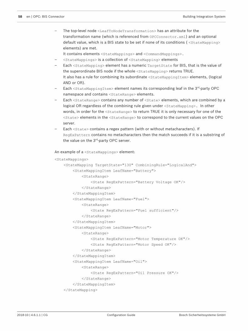
58 en | OPC: BIS Connector Building Integration System
2018-10 | 4.6.1.1 | CG Configuration Guide Bosch Sicherheitssysteme GmbH
– The top-level node <LeafToNodeTransformation> has an attribute for the
transformation name (which is referenced from OPCConnector.xml) and an optional
default value, which is a BIS state to be set if none of its conditions ( <StateMapping>
elements) are met. It contains elements <StateMappings> and <CommandMappings>.
– <StateMappings> is a collection of <StateMapping> elements
– Each <StateMapping> element has a numeric TargetState for BIS, that is the value of
the superordinate BIS node if the whole <StateMapping> returns TRUE.
It also has a rule for combining its subordinate <StateMappingItem> elements, (logical
AND or OR).– Each <StateMappingItem> element names its corresponding leaf in the 3rd-party OPC
namespace and contains <StateRange> elements.
– Each <StateRange> contains any number of <State> elements, which are combined by a
logical OR regardless of the combining rule given under <StateMapping>. In other
words, in order for the <StateRange> to return TRUE it is only necessary for one of the
<State> elements in the <StateRange> to correspond to the current values on the OPC
server.
– Each <State> contains a regex pattern (with or without metacharacters). If
RegExPattern contains no metacharacters then the match succeeds if it is a substring of
the value on the 3rd-party OPC server.
An example of a <StateMappings> element:
<StateMappings>
<StateMapping TargetState="130" CombiningRule="LogicalAnd">
<StateMappingItem LeafName="Battery">
<StateRange>
<State RegExPattern="Battery Voltage OK"/>
</StateRange>
</StateMappingItem>
<StateMappingItem LeafName="Fuel">
<StateRange>
<State RegExPattern="Fuel sufficient"/>
</StateRange>
</StateMappingItem>
<StateMappingItem LeafName="Motor">
<StateRange>
<State RegExPattern="Motor Temperature OK"/>
<State RegExPattern="Motor Speed OK"/>
</StateRange>
</StateMappingItem>
<StateMappingItem LeafName="Oil">
<StateRange>
<State RegExPattern="Oil Pressure OK"/>
</StateRange>
</StateMappingItem>
</StateMapping>

Building Integration System OPC: BIS Connector | en 59
Bosch Sicherheitssysteme GmbH Configuration Guide 2018-10 | 4.6.1.1 | CG
BIS commands for nodes transformed by LeafToNode transformationsAs with the NodeToLeaf transformations, BIS OPC Connector can receive BIS controlcommands and write strings to the DA items of the 3rd party OPC server. With LeafToNodetransformations however there exists an additional <CommandMappings> section in the
transformation description, where new BIS control commands can be defined. This isstructured as follows:– The <CommandMappings> collection contains <CommandMapping> elements
– Each <CommandMapping> element names its command and contains
<CommandMappingItem> elements.
– Each <CommandMappingItem> element names the target leaf node on the 3rd-party OPC
server (LeafName), and the value (State)to which the leaf should be set.
An example of a <CommandMappings> element follows. The command “Reset fuel and oil” will
become available in BIS as a command that can be invoked by right-click and writes to therespective OPC server.
<CommandMappings>
<CommandMapping CommandName="Reset fuel and oil">
<CommandMappingItem LeafName="Fuel" State="Fuel sufficient"/>
<CommandMappingItem LeafName="Oil" State="Oil Pressure OK"/>
</CommandMapping>
</CommandMappings>
6.2.2 OPCConnector.xmlThis XML file contains a single element <OpcConnector> two sub-elements:
<SourceOPCServer> and <Transformations>.
<OpcConnector> has a single attribute LowestHierarchyLevel, which tells BIS whether the
OPC Connector namespace terminates in groups, detectors, or in the individual sensors inthose detectors. For instance, a fire detector can belong to a group of peers, and can contain3 different sensors, which sense temperature, light and chemical changes respectively.
The <SourceOPCServer> element tells OPC Connector where to find the 3rd party OPC server,
either on LOCALHOST or on a named computer. It also contains GUIDs (global uniqueidentifiers) for the DA (data access) and AE (alarm and event) parts of the 3rd party OPCservers.Thus the first few lines of OPCConnector.xml will look similar to the following:
<?xml version="1.0" encoding="UTF-8"?>
<OpcConnector LowestHierarchyLevel="Detector">
<SourceOPCServer ComputerName="LOCALHOST"
DaGuid="{A49A67C1-9CA2-4503-A220-A07F2A1DAFFE}"
AeGuid="{E8BBA3A4-16F0-4AC1-9FA2-A30771B2AFFE}"/>
The <Transformations> element contains all the transformations that the OPC Connector is
to perform. Each of its <Transformation> sub-elements describes one of these
transformations, using up to three attributes. These attributes are:– OPCItemPathSource: The path, within the 3rd party OPC server’s namespace, of the node
to be transformed– OPCItemPathTarget: The path, within the BIS namespace, of the corresponding BIS
node.

60 en | OPC: BIS Connector Building Integration System
2018-10 | 4.6.1.1 | CG Configuration Guide Bosch Sicherheitssysteme GmbH
– TransformationTypeName: The name of the transformation as defined in the
TransformationTypes.xml file.
The combination and the contents of these three attributes determine what kinds oftransformations are possible. The following tables show which combination of parameters isrequired for which kinds of transformation. Eight transformation types are shown, A-H anddescribed in detail below the table.
OPCItemPathSource
OPCItemPathTarget
TransformationTypeName
Possible goal> A) Ignore items on theOPC server.
B) Pass item valuesunchanged
C) Transform namespace but notleaf values
OPCItemPathSource
OPCItemPathTarget
TransformationTypeName
(Bitfield) (RegEx)
Possible goals>
D) Transform leafvalues but notnamespace.(RegExToLeafwithout subleaves)
E) "Bitfield parsing":Turn a decimal leafvalue into a bit field,parse it andtransform it into aset of decimal BISsubleaf values.(BitFieldToLeaf)
G) "String Differentiation": Parsea string value into a set ofnumeric BIS subleaf values.(RegExToLeaf)
F) "Concentration":Use combining-rules to transform multiple leaf valuesinto a single BIS (numeric) leaf value.(LeafToNode)
H) "String Analysis": Parse andanalyse a string value, and writethe result to a single BIS numericleaf value(RegExToLeaf without subleaves)
Table 6.1: (table continues…)

Building Integration System OPC: BIS Connector | en 61
Bosch Sicherheitssysteme GmbH Configuration Guide 2018-10 | 4.6.1.1 | CG
A) Ignore items on the OPC serverIn the simplest case, all that is required to filter out or ignore an item on the 3rd party OPCserver is to leave it out of OPCConnector.xml entirely. These items will not be visible to BIS.
B) Pass item values unchangedIf an item on the party OPC server is mentioned in the first parameter attribute(OPCItemPathSource) but not in the other two, then it will appear in the namespaces of OPC
connector and BIS, but will not be transformed or the namespace re-mapped in any way.Nevertheless the current value, and any changes, will be reported to BIS, and the BIS user maychange the value of the item on the OPC server by right-clicking the item in the devicehierarchy in BIS and selecting the command Set value.This kind of transformation mapping is roughly equivalent to the functionality of the BIS State-forwarding OPC server.The following is an example of this transformation type from OPCConnector.xml Note that
the third parameter TransformationTypeName is absent:
<Transformation
OPCItemPathSource="Source.Sample0.NoTransformation"
OPCItemPathTarget=""/>
C) Transform namespace but not leaf valuesIf the first two parameter attributes (OPCItemPathSource, OPCItemPathTarget) are givennamespace paths, but the third parameter is absent, then OPC Connector performs a mappingof paths, but does not transform the values at the leaf nodes.This transformation type is useful for simplifying overly complex namespaces within BIS, or forshortening long item names.The following is an example of this transformation type from OPCConnector.xml Note that
the third parameter TransformationTypeName is absent:
<Transformation
OPCItemPathSource="Source.Sample1.NamespaceTransformation.This.Is.A.Sou
rce.Path.String.With.A.Lot.Of.Hierarchy.Levels"
OPCItemPathTarget="Target.Sample1.Short.Hierarchy"/>
D) Transform leaf values but not namespaceIf the first and third parameter attributes are given values, but OPCItemPathTarget left
empty, then the OPC server’s namespace is mirrored in BIS, and the leaf value subjected tothe transformation named in the third parameter (and defined inTransformationTypes.xml).
Example:
<Transformation
OPCItemPathSource="Source.Sample0.Lighting"
OPCItemPathTarget=""
TransformationTypeName="BitFieldSmall"/>

62 en | OPC: BIS Connector Building Integration System
2018-10 | 4.6.1.1 | CG Configuration Guide Bosch Sicherheitssysteme GmbH
E) "Bit field parsing": Turn a decimal leaf value into a bit field, parse it and transform it intoa set of decimal BIS subleaf values (BitFieldToLeaf)If all three parameters are set, and the transformation named underTransformationTypeName is defined in TransformationTypes.xml, then an integer on an
OPC server’s leaf item, can be turned into a bit field, and the bit field parsed into values formultiple BIS leaf items. There are two examples given in the TransformationTypes.xml in
the BIS installation kit, namely BitFieldBig and BitFieldSmall.
<Transformation
OPCItemPathSource="Source.Sample2.BitFieldToLeafTransformation.Building
"
OPCItemPathTarget="Target.Sample2.Building"
TransformationTypeName="BitFieldBig"/>
F) "Concentration": Use combining-rules to transform multiple leaf values into a single BIS(numeric) leaf value. (LeafToNode)All three parameters are set. The transformation named under TransformationTypeName is
defined in TransformationTypes.xml, It contains one or more <StateMapping> elements
that are each complex patterns to be compared with the current leaf values on the 3rd partyOPC server. If a <StateMapping> matches then the numeric value of its TargetState
attribute is set in BIS.
<Transformation
OPCItemPathSource="Source.Sample4.LeafToNode.Car"
OPCItemPathTarget="Target.Sample4.Car Summary"
TransformationTypeName="LeafToNode"/>
G) "String Differentiation": Parse a string value into a set of numeric BIS subleaf values.(RegExToLeaf)If all three parameters are set, and the transformation named underTransformationTypeName is defined in TransformationTypes.xml, then a string on an
OPC server’s leaf item can be parsed using regular expressions, and any number of BIS leafitem states set as a result.In OPCConnector.xml such a transformation will look similar to the following:
<Transformation
OPCItemPathSource="Source.Sample3.RegExWithLeafs.Car"
OPCItemPathTarget="Target.Sample3.Car"
TransformationTypeName="RegExWithLeafs"/>
In TransformationTypes.xml there are examples, namely RegExWithLeafs and
RegExWithNumbers.
In RegExWithLeafs, for example, the OPC Connector browses specific leaves (as specified
by the attribute LeafName) on the 3rd party OPC server and sets different BIS states
depending on what RegExPattern elements match the strings it finds there.
<Transformation LeafName="Battery">
<RegExItem RegExPattern="Battery Voltage low" ActivationState="111"/>
<RegExItem RegExPattern="Battery Voltage high" ActivationState="112"/>
<RegExItem RegExPattern="Battery Voltage OK" ActivationState="118"/>

Building Integration System OPC: BIS Connector | en 63
Bosch Sicherheitssysteme GmbH Configuration Guide 2018-10 | 4.6.1.1 | CG
</Transformation>
<Transformation LeafName="Fuel">
<RegExItem RegExPattern="Low on Fuel" ActivationState="113"/>
<RegExItem RegExPattern="Fuel sufficient" ActivationState="119"/>
</Transformation>
Notice!Cause of HazardNote that there is, by design, no “catch-all” or “else” clause. If none of the regex patternsmatch then no actions are undertaken
H) "String Analysis": Parse and analyse a string value, and write the result to a single BISnumeric leaf value (RegExToLeaf without subleaves)
<Transformation
OPCItemPathSource="Source.Sample3.RegExWithoutLeafs.PLZ"
OPCItemPathTarget="Target.Sample3.PLZ"
TransformationTypeName="RegExWithoutLeafs"/>
In RegExWithoutLeafs the attribute LeafName is left empty in TransformationTypes.xml,
so the OPC Connecter instead parses the value of the single node it finds in theTransformation’s OPCItemPathTarget attribute. Based on the regex parse of the string value,
it sets BIS states to the integer given in the attribute ActivationState.
<RegExToLeafTransformation Name="RegExWithoutLeafs" ActivationState="148"
DeactivationState="149">
<Transformation LeafName="">
<RegExItem RegExPattern="D-[8-9]\d{4}$" ActivationState="140"/>
<RegExItem RegExPattern="D-7\d{4}$" ActivationState="141"/>
<RegExItem RegExPattern="D-6\d{4}$" ActivationState="142"/>
…
6.3 Invocation from BISAdding OPC connector to a BIS configurationBIS OPC Connector can be “browsed” in the same way as other OPC servers. This is notstrictly necessary but has the advantage that BIS automatically starts the server for you whenthe configuration is loaded. If you choose not to add OPC Connector as a subsystem it willneed to be started manually, as described below:If you are unfamiliar with the procedure to browse a subsystem, follow the steps below:Prerequisite: A BIS version 3.0 or greater has been installed, whereby the option to install theBIS OPC connector was confirmed during the installation.1. In the BIS configuration browser select the Outlook button Connections2. In the upper-left dialog pane, under Connection servers, right-click the server where OPC
Connector resides, and select Add subsystem…3. From the popup dialog’s list of configurable OPC servers select OPCConnector4. Click OK
Result: OPCConnector has appeared under the selected connection server5. Click the OPCConnector icon

64 en | OPC: BIS Connector Building Integration System
2018-10 | 4.6.1.1 | CG Configuration Guide Bosch Sicherheitssysteme GmbH
Result: Two dialog panes appear: OPC server (available elements) and BIS addresses(chosen elements)
6. Click the Connect button to “browse” the server.Result: OPCConnector appears in the left pane.
7. Right click OPCConnector in the first pane and select Expand all (browse all if notalready browsed)Result: The entire namespace of OpcConnector as defined in OPCConnector.xml and
TransformationTypes.xml is displayed in the left pane.
8. Right click OPCConnector in the first pane and select Add all items. Confirm yourselection in the popup dialog.Result: The entire namespace of OPCConnector is copied to the right-hand pane
9. Click the Apply button to commit the addresses to BIS.10. Click the Disconnect button to stop browsing the server.11. In the BIS Manager load this modified configuration
Monitoring OPC Connector from the BIS client.Prerequisite: The BIS server is running the configuration that has been modified as per theprevious section.4 In the BIS client, open the Location overview tab and select Detectors without location
in the left pane.Result: The devices, groups and detectors of the OPC Connector are listed in the mainpane. Sort the Address column alphabetically, and look for addresses starting withOPCConnector
Familiarizing yourself with OPC connector using the “demo” OPC serverThis BIS installation includes a “demo” OPC server that demonstrates the main features of BISOPC Connector.If OPCConnector has been added as a subsystem in your configuration, then the demo OPCserver will be started by BIS when the configuration is loaded.
If OPCConnector has not been added by browsing, it may be started manually as follows:The files can be found on the BIS installation drive under MgtS\Connections
\DemoOpcServer\
1. Back up the file DemoOpcServer.xml under an appropriate name, e.g.
DemoOpcServer_ORIGINAL.xml
2. Copy the file DemoOpcServer_OPCConnector.xml onto the file DemoOpcServer.xml,
thus overwriting it.3. Double-click DemoOpcServer.exe in the same directory. It will now set its DA item values
according to the code in DemoOpcServer.xml
Using the continuous loop in the demo OPC serverDA item values can be set by a continuous loop defined in DemoOpcServer.xml or manually
using the Softing OPC Client.The Demo OPC server defines a namespace hierarchy and a loop in which DA values arewritten to the leaves of that namespace. The attribute Delay defines the period of the loop in
milliseconds. If Delay is set to “0“ or Loop set to “false”, then the leaf item values remain
static unless set manually.
<DaItemValues Delay="1000" Loop="true">

Building Integration System OPC: BIS Connector | en 65
Bosch Sicherheitssysteme GmbH Configuration Guide 2018-10 | 4.6.1.1 | CG
<DaItemValue Path="Source.BitFieldToLeafSmall.Car" Value="1"/>
<DaItemValue Path="Source.BitFieldToLeafSmall.Car" Value="2"/>
<DaItemValue Path="Source.BitFieldToLeafSmall.Car" Value="4"/>
…
</DaItemValues>
Setting values manually using the Softing OPC client.This BIS installation includes the Softing OPC client that can be used to set leaf values on anOPC server, and so to test BIS OPC Connector.The Softing client, SOClient.exe, can be found on the BIS installation drive under MgtS
\Tools\Softing
Prerequisite: A BIS version 3.0 or greater has been installed, whereby the option to install theBIS OPC connector was confirmed during the installation.Prerequisite: The OPC Connector is running, either started by BIS (because it has beenbrowsed into your configuration), or started manually. The continuous loop can but need notbe in operation.1. Start the Softing Client SOClient.exe.
2. In the main pane, OPC Servers tab, click Local > Data Access V33. Double-click DemoOpcConnector DA
Result: DemoOpcServer DA appears in the left pane with green icons showing that thisOPC server is running
4. In the main pane, DA Browse tab, right-click DemoOpcServer DA and selectAdd Items for all TagsResult: The various DA Items are listed on the DA Items tab
5. In the main pane, DA Items tab you may now write a value to one of the DA Items by left-clicking it, then entering a value in the text entry box upper-right corner, then clicking theWrite button.

66 en | Common configuration recipes Building Integration System
2018-10 | 4.6.1.1 | CG Configuration Guide Bosch Sicherheitssysteme GmbH
7 Common configuration recipesBIS is a large and highly configurable integration platform in its own right. In this section weoutline the steps for a small number of common configuration types. Your own configurationmay require steps from more than one of these configuration types.
A A basic BIS configuration containingthe essential features.Configuration A. A basic BISconfiguration, page 66
C A configuration which adds active locationplans (floor plans) to configuration B.
The ability to deploy location plans is licensedseparately. With it operators navigate withinand control devices from a graphical maprepresentation of the installation site.Configuration C: Adds active location plans(floor plans) to configuration B., page 68
B A configuration with the followingenhancements:– Address lists: useful for
manipulating logical groups ofdetectors and other devices.
– Symbols: useful for makingdevices more conspicuous andeasily identifiable on userinterface pages
– State/condition counters: usefulfor summarizing the overallstatus of many devices of thesame type.
Configuration B: Includesenhancements from the basicpackage., page 67
D A configuration which adds dynamic htmlpages to configuration C.
The ability to deploy dynamic html pages inthe BIS UI, e.g. “action plans”, is licensedseparately. With it operators can be givenprompt, clear instructions for dealing withrare, complex or dangerous emergencysituations.Configuration D: Adds dynamic html pages (e.g.action plans) to configuration C., page 69
7.1 Configuration A. A basic BIS configuration
The following procedure describes a basic BIS configuration which contains none of theoptional BIS features that are licensed separately. It can be regarded as a commondenominator for most BIS configurations.
Step# Example configuration #1: Step descriptions
1 Verify that the prerequisites have been fulfilled: Prerequisites of configuration, page25
2 Configure the event log size and backup options in the BIS Manager:The Event log tab, page 105 andEvent log Administrator Settings, page 110
3 Create an initial empty configuration: Setting up an initial BIS configuration, page 30
4 Import and activate any additional license features: Licensing the BIS server, page 25

Building Integration System Common configuration recipes | en 67
Bosch Sicherheitssysteme GmbH Configuration Guide 2018-10 | 4.6.1.1 | CG
Step# Example configuration #1: Step descriptions
5 Configure the server structure, that is, the network of connection servers and otherswhich are to participate in this BIS installation: Server structure, page 116
6 Define connections and assign addresses:Connections and Addresses, page 135andOPC classic connections, page 45
7 Define address lists: Address lists, page 167
8 Define detector types: Detector type, page 149
9 Define states: States, page 145
10 Define associations:Associations (Jobs) - an overview, page 173General procedure for configuring Associations, page 178For reference:Example of tracking totals using Associations, page 180Example of configuring a security system using Associations, page 182
11 Define operators and authorizations:Operators, page 124Authorizations, page 118
12 Configure event log entries and permissions: Event log, page 194
7.2 Configuration B: Includes enhancements from the basicpackage.
The following procedure describes a BIS configuration which refines addresses, detectortypes, states and associations with– Address lists: useful for manipulating logical groups of detectors and other devices.– Symbols: useful for making devices more conspicuous and easily identifiable on user
interface pages– State/condition counters: useful for summarizing the overall status of multiple devices of
the same type.The above enhancements belong to the BIS basic package and do not need to be purchased inaddition.
Step# Example configuration #2: Step descriptions
1 Verify that the prerequisites have been fulfilled: Prerequisites of configuration, page25
2 Configure the event log size and backup options in the BIS Manager:The Event log tab, page 105 andEvent log Administrator Settings, page 110
3 Create an initial empty configuration: Setting up an initial BIS configuration, page 30
4 Import and activate any additional license features: Licensing the BIS server, page 25
5 Configure the server structure, that is, the network of connection servers and otherswhich are to participate in this BIS installation: Server structure, page 116
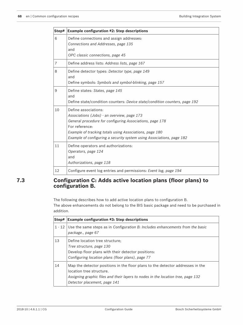
68 en | Common configuration recipes Building Integration System
2018-10 | 4.6.1.1 | CG Configuration Guide Bosch Sicherheitssysteme GmbH
Step# Example configuration #2: Step descriptions
6 Define connections and assign addresses:Connections and Addresses, page 135andOPC classic connections, page 45
7 Define address lists: Address lists, page 167
8 Define detector types: Detector type, page 149andDefine symbols: Symbols and symbol-blinking, page 157
9 Define states: States, page 145andDefine state/condition counters: Device state/condition counters, page 192
10 Define associations:Associations (Jobs) - an overview, page 173General procedure for configuring Associations, page 178For reference:Example of tracking totals using Associations, page 180Example of configuring a security system using Associations, page 182
11 Define operators and authorizations:Operators, page 124andAuthorizations, page 118
12 Configure event log entries and permissions: Event log, page 194
7.3 Configuration C: Adds active location plans (floor plans) toconfiguration B.
The following describes how to add active location plans to configuration B.The above enhancements do not belong to the BIS basic package and need to be purchased inaddition.
Step# Example configuration #3: Step descriptions
1 - 12 Use the same steps as in Configuration B: Includes enhancements from the basicpackage., page 67
13 Define location tree structure;Tree structure, page 130Develop floor plans with their detector positions:Configuring location plans (floor plans), page 77
14 Map the detector positions in the floor plans to the detector addresses in thelocation tree structure.Assigning graphic files and their layers to nodes in the location tree, page 132Detector placement, page 141

Building Integration System Common configuration recipes | en 69
Bosch Sicherheitssysteme GmbH Configuration Guide 2018-10 | 4.6.1.1 | CG
7.4 Configuration D: Adds dynamic html pages (e.g. action plans)to configuration C.
The following describes how to add active location plans to configuration B.These enhancements do not belong to the BIS basic package, and need to be purchased inaddition.
Step# Example configuration #4: Step descriptions
1 - 14 Use the same steps as inConfiguration B: Includes enhancements from the basic package., page 67and thenConfiguration C: Adds active location plans (floor plans) to configuration B., page 68
15 Create action plans and miscellaneous documentsCreating/Editing Action Plans and Action Buttons, page 80
16 Map the action plans and the miscellaneous documents to locations.Assigning action plans and miscellaneous documents to nodes in the location tree, page133Detector placement, page 141
17 Configure print options.Alarm print, page 196Protocol print, page 198Assigning automatic alarm printouts to nodes in the location tree, page 134

70 en | Template jobs Building Integration System
2018-10 | 4.6.1.1 | CG Configuration Guide Bosch Sicherheitssysteme GmbH
8 Template jobsDescription of the prerequisites and the configuration of Template jobs in the BIS system.
8.1 Introduction and overviewA Job in BIS is a kind of Association. A Job is a collection of IF-THEN rules which respond inreal time to events and state-changes in the BIS system. Each of these rules must have aprerequisite “Meta-IF” condition called a Trigger. For this reason the rules themselves areoften referred to as Triggers. Optionally each rule may contain IF, THEN and ELSE clauses,though of course without a THEN clause the rule can have no effect.
The Template job feature is a powerful way to create large numbers of related rules whichdiffer only in their addresses and/or parameters e.g. rules for hundreds of hotel rooms or firedetectors.
The overall process for defining and using template jobs is as follows:1. Template jobs are defined in the BIS Configuration Browser like conventional jobs, but
using generic placeholders in place of narrowly defined parameters.2. The template job is then exported to an Excel file, where each row can represent a rule
and the respective columns can hold values for all the parameters required.3. The rules are edited in Excel where it is relatively easy to create large tables of
sequentially numbered items, e.g. camera_1, camera_2, camera_n or IP addresses
x.y.z.1, x.y.z.2 etc.
4. When the template job table is complete, BIS first checks it for consistency, and then it isre-imported into the Configuration Browser.
5. BIS then creates a virtual rule for each row in template job table, i.e. for each of therelated doors, cameras etc.
8.2 Prerequisite softwareBosch Building Integration System (BIS)BIS version 2.2 or higher.
Microsoft ExcelTo use this feature Microsoft Excel (versions 2007 and later are recommended) must beinstalled on the machine where the BIS Configuration Browser is started. If not, then the BISConfiguration Browser will not allow jobs to be made into template jobs.
Notice!A separate installation of the Template Job OPC server is no longer necessary as it is includedin BIS versions 2.2 and higher.
8.3 Creating a connection to the Template Job OPC server1. Start the BIS Configuration Browser2. Select Connections in the left-hand Outlook bar.3. Right-click the connection server name in the upper left server tree or click the [+] button
to create a connection (i.e. an OPC Subsystem) for the Template Job OPC server.4. In the Select new subsystem dialog select Generic OPC Server.5. In the Data Access pane select Bosch.TemplateJob.DA

Building Integration System Template jobs | en 71
Bosch Sicherheitssysteme GmbH Configuration Guide 2018-10 | 4.6.1.1 | CG
6. Click OK to close the dialog box. Effect: The Bosch.TemplateJobDA OPC server is added below the Connection serverthat you selected.
Note: This OPC server is only needed for the creation of template jobs, and so only duringconfiguration, not during runtime. Therefore its check box is automatically cleared to preventit from starting automatically when the BIS application starts.
Notice!Do not change the predefined subsystem name BoschTemplateJobDA
1. In the Connection servers tree (upper left pane), click BoschTemplateJobDA.2. Press the Connect button above the middle pane, then right-click BoschTemplateJobDA
server in the middle pane and select Add all items from its context menu.3. Effect: The template parameter Parameter appears as an item within
BoschTemplateJobDA in the middle pane. This parameter can be used as a placeholderwithin Associations in later steps.
4. Press the Disconnect button above the middle pane before proceeding to definetemplate jobs.
8.4 Using placeholders for addresses and states in a jobCreate a new job in the Configuration Browser as follows:1. Select Configuration Browser Outlook bar > General settings > Associations in the upper
left pane.2. Click the New button next to Job, and give the job a new and unique name for better
orientation in the Excel tables to be generated later.3. Similarly click the New button next to Trigger , select Type: Address from the pull down
menu, and give it a new and unique name in the Comment field of the pop-up window.Click OK.Effect: The Address selection dialog appears.
4. In the Devices pane select BoschTemplateJobDA, and in the Groups pane select
Parameter
5. Click OKEffect: a dialog box appears where you can define the state transition (From <state-1>; to<state-2>) that will act as trigger for the current job.
6. If you wish these transition states (From and to) to be read from the Excel file, select998-Template state from the respective pull-down menus.

72 en | Template jobs Building Integration System
2018-10 | 4.6.1.1 | CG Configuration Guide Bosch Sicherheitssysteme GmbH
7. Effect: the following example shows a trigger with a template address(BoschTemplateJobDA.Parameter) to be triggered by a transition from any state(wildcard *) to 998-Template state which will later be instantiated from the Excel table.
8. Click the Apply button to save the trigger9. Right-click the trigger and add any further IF, THEN and ELSE clauses you require.
Notice!Ensure that all trigger names for template jobs are unique.
8.5 Marking a job as a Template JobTo turn a job into a template job, right-click the job’s icon and select Select template from itscontext menu.Effect: The job’s icon will be overlaid by a red letter T. While a job is marked as a template jobit can not be modified.
Enabling the modification of a template jobTo enable the modification of a template job’s parameters, IF-conditions, and THEN/ELSEcontrols, first reverse the above procedure by right-clicking and selecting Unselect templatefrom its context menu.Effect: Any imported template data for this job is removed from the configuration and the jobcan be modified. The letter T disappears from the icon.
8.6 Exporting placeholder data to an Excel fileWhen a job is thus marked as a Template job, with a letter T, the placeholder data can beexported to Excel. Proceed as follows:
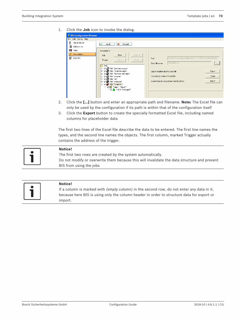
Building Integration System Template jobs | en 73
Bosch Sicherheitssysteme GmbH Configuration Guide 2018-10 | 4.6.1.1 | CG
1. Click the Job icon to invoke the dialog.
2. Click the […] button and enter an appropriate path and filename. Note: The Excel file canonly be used by the configuration if its path is within that of the configuration itself
3. Click the Export button to create the specially formatted Excel file, including namedcolumns for placeholder data
The first two lines of the Excel file describe the data to be entered. The first line names thetypes, and the second line names the objects. The first column, marked Trigger actuallycontains the address of the trigger.
Notice!The first two rows are created by the system automatically.Do not modify or overwrite them because this will invalidate the data structure and preventBIS from using the jobs
Notice!If a column is marked with (empty column) in the second row, do not enter any data in it,because here BIS is using only the column header in order to structure data for export orimport.

74 en | Template jobs Building Integration System
2018-10 | 4.6.1.1 | CG Configuration Guide Bosch Sicherheitssysteme GmbH
In this example above we have one column for a trigger addresscalled Trigger with the name Trigger1, and one column for a stateTo with the trigger name Trigger1. This corresponds to thescreenshot below where both the trigger address and the To statehave placeholders, but the From state has a wildcard asterisk.
8.7 Entering real addresses and states in the Excel fileNow real addresses and states can be entered in the Excel file.All addresses and states must exist in the configuration and must be typed in as completeaddress strings.In the following example we have a LSN connection with the address strings “LSN.1.1” to“LSN.5.5” and use the state values from 11 to 55.
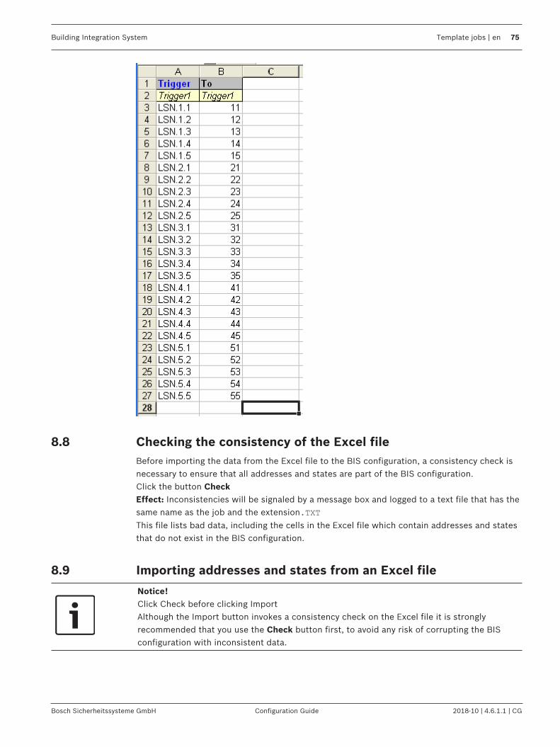
Building Integration System Template jobs | en 75
Bosch Sicherheitssysteme GmbH Configuration Guide 2018-10 | 4.6.1.1 | CG
8.8 Checking the consistency of the Excel fileBefore importing the data from the Excel file to the BIS configuration, a consistency check isnecessary to ensure that all addresses and states are part of the BIS configuration.Click the button CheckEffect: Inconsistencies will be signaled by a message box and logged to a text file that has thesame name as the job and the extension.TXT
This file lists bad data, including the cells in the Excel file which contain addresses and statesthat do not exist in the BIS configuration.
8.9 Importing addresses and states from an Excel file
Notice!Click Check before clicking ImportAlthough the Import button invokes a consistency check on the Excel file it is stronglyrecommended that you use the Check button first, to avoid any risk of corrupting the BISconfiguration with inconsistent data.
76 en | Template jobs Building Integration System
2018-10 | 4.6.1.1 | CG Configuration Guide Bosch Sicherheitssysteme GmbH
Click the button ImportEffect: BIS generates one job for each line in the body of the Excel file. The configuration ofthe template job is complete, and the configuration can be used by the system. The icon ofthe job is overlaid with a green letter T.The template job is set unmodifiable. To reverse this, see Marking a job as a Template Job, page72
8.10 Notes and LimitationsUpper limit for Jobs, TriggersThe number of jobs and triggers which can be created by this feature is limited. The highestnumber that has been tested is currently 150,000 triggers.
Notice!In order to reach this upper limit it may be necessary to install RAM in excess of 1 GB,depending also on the needs of other installed software.
Do not change the BIS configuration while a template job .XLS file is openClose any .XLS files pertaining to template jobs before saving and reloading a BISconfiguration. Having an open.XLS file in the configuration can prevent reloading.
Deleting addressesIf you delete addresses in the Configuration Browser it is necessary to check whether they arecontained in the imported Excel files of your template jobs.If this is the case then unselect the template job, remove the addresses from the Excel file,select the job again as template job and re-import the Excel file.Use the Check button to produce a list of states and addresses missing from BIS. SeeChecking the consistency of the Excel file, page 75
Deactivating template jobsA template job currently can not be deactivated by clearing its check box under Associations >Jobs. To deactivate the template job it is necessary to delete it.
Changing “monitored by camera” documentsA monitored by camera document cannot be changed while still associated with a camera.First delete the associated camera and then reconfigure the job with a different camera andthe appropriate html document.
Building Integration System Customizing BIS operator interfaces | en 77
Bosch Sicherheitssysteme GmbH Configuration Guide 2018-10 | 4.6.1.1 | CG
9 Customizing BIS operator interfaces9.1 Authentication
In the Configuration Browser select Outlook bar: Administration > Server Structure to set theclient authentication parameters.In order to authenticate a user BIS first examines its own user data. If the user exists in theBIS user data, BIS will run a user authentication on the login server.For this reason, if a user has different passwords on the login server and on the clientworkstation, it is his password for the login server which is required for logging into BIS.
Configuring a Windows Authentication Scenario with local usersWhen using Windows Authentication with a BIS login dialog, users must always enter theusername / password combination they have on the BISlogin server. There is no need, as faras BIS is concerned, for the user account to exist on the client. For domain users e.g.“myDomain\johnsmith” the same rule applies: The login server tries to authenticate locally,which will work as long as these users are known to the login server.
Windows Authentication without password dialogThe dialogless login takes the credentials of the user logged in to the current client and sendsthem to the server (credentials can be considered as username and password for presentpurposes). The client verifies only that it knows the password, and does not transmit it to theserver. Hence it is impossible to capture the user's password from this credential sendingprocess.When the BIS server receives these credentials, it looks into it's BIS user database and triesto use the transferred credentials to authenticate the user locally on the server.To Windows Authentication with a BIS dialogless login page, the user’s name and passwordneed to be identical on the login server and the client. To ensure this, we recommend the useof domain users.
Setting up a special Authentication methodTo configure a BIS system to one of the three possible authentication methods (BISauthentication, Windows Authentication, Dialogless Authentication), the BIS login HTML filemust be adapted. The file Login.htm is located in MgtS\HTML-Login and provides thefunctionality for BIS authentication. Please overwrite Login.htm with one of the alternativesprovided: Login_WindowsAuthentication.html orLogin_AutomaticallyLogonCurrentUser.htm .
9.2 Configuring location plans (floor plans)
9.2.1 Creating location plansLocation plans (floor plans) are a substantial enhancement to any BIS installation. With theman operator understands much faster the location and potential consequences of an alarmstate.It is usually the site architect, and not the BIS configurator, who produces location plans anddefines the names and position of detectors. It is then the job of the BIS configurer to map thesub-areas and device positions in the graphics to the locations and devices within the BISconfiguration, see Detector placement, page 141. Therefore below we provide only a briefsummary of the two important aspects of location plans for the BIS configurator:– Best practices for creating location plans, page 78– Defining named sections, page 78– Anchoring detectors in graphics using hyperlinks, page 78– Saving the floor plan for use in the BIS client, page 79

78 en | Customizing BIS operator interfaces Building Integration System
2018-10 | 4.6.1.1 | CG Configuration Guide Bosch Sicherheitssysteme GmbH
9.2.2 Best practices for creating location plansRegarding the use of AutoCAD graphics we recommend the following practices to optimizeease of use and performance.
Ease of use– Place information that is relevant to different purposes or persons on separate layers. A
layer can then be displayed or hidden depending on the person viewing it. Fire detectors,and burglar alarms, for example, are usually best placed on separate layers.
– Give each layer a unique name according to a consistent, agreed nomenclature. Forexample, use a numbering scheme to reflect floors, areas and sub-areas.
– For consistency of zoom factors and other settings use plot templates.
Performance– Keep the number of layers and objects as small as possible. For example, document only
features that are essential for orientation, such as walls, doors, windows, and staircases.– Likewise remove unessential legend tables, headers, external references (xrefs ) and
other hyperlinks.– In any drawing file the number of 3D hyperlink symbols should not exceed 300. The
number of 2D hyperlink symbols should not exceed 500.– Use only standard fonts and only colors defined by the respective layer.– The size of a drawing file should not exceed 1MB.
9.2.3 Defining named sectionsIn the floor plans, named sections can be defined which you can assign like an independentgraphic to a location in the location structure (for example, the individual rooms of a floor canbe created as named sections).1. Open AutoCAD and create a .dwg file.2. Draw the desired floor plan.3. From the main menu, select View, then Named Views...4. Click Button: New, then in the New View dialog box select Define window.5. Click the arrow icon. Drag a rectangle around the named section, then click once to
complete the rectangle.6. Right-click to return to the New View dialog box.7. In the View Name field, enter a name for the named section. Close the dialog boxes by
clicking OK.
Notice!Do not use the period (.), asterisk (*), or question mark (?) symbols in the names of namedsections.
9.2.4 Anchoring detectors in graphics using hyperlinksIf displaying detectors on the floor plans, anchor them in the graphics using AutoCAD'shyperlink function.1. Open AutoCAD and create a .dwg file.2. Draw the desired floor plan.3. To anchor a detector in the graphic, draw a square of the size of the future detector icon.
Position the square where the detector graphic is to appear.

Building Integration System Customizing BIS operator interfaces | en 79
Bosch Sicherheitssysteme GmbH Configuration Guide 2018-10 | 4.6.1.1 | CG
4. On the Insert menu, select Hyperlink. The mouse cursor changes to a small rectangle.Click the square you drew in the previous step to select it. Press Enter to confirm theselection. The Insert hyperlink dialog opens.
5. Enter a name for the hyperlink in the Type filename or name of website field byconcatenating the connection and detector point names using a period character “.” asseparator. See the examples below. This reduces configuration effort because BIS is thenable to assign the detector names automatically.Examples of well-formed BIS detector names:- UGM.27 = UGM connection, Group 27- UGM.UEZ2.35.2 = UGM connection, subsystem UEZ2, group 35, detector 2
6. Remove any text from the Text to display box if you do not wish text to appear in thelocation plan.
7. Select the Use relative path for hyperlink check box.8. Click OK to close the Insert hyperlink dialog.
Notice!Do not use the asterik (*) or question mark (?) symbols in the names of named sections.Only use the period (.) as a separator.
9.2.5 Saving the floor plan for use in the BIS clientTo become viewable in the BIS client an AutoCAD source file, in DWG format, must be“plotted” to a viewable format e.g. DWF. Note however that the plotting process is notreversible. Hence you should always back up both the source files and the viewable/plottedfiles.
Perform the following procedure in AutoCAD to generate the .dwf viewable format:1. Click menu: File > Plot… to open the Plot dialog box.2. Depending on the version of AutoCAD you are using, select the appropriate plotter name
in the Plot - Model dialog. If the required plotter name is not in the list it may need to beinstalled. In this case please consult a knowledgeable AutoCAD user. The table belowgives recommendations for plotter names.
AutoCAD version Recommended plotter name
AutoCAD-LT 2000 to 2006 Whip 3.1 compatible
AutoCAD-LT 2007 Standard R14
AutoCAD-LT 2008 and later DWF-eView (optimized for view)orDWF-ePlot (optimized for plot)
4 Make the necessary entries, e.g. for paper size and click OK. When plotted the filename isautomatically given the .DWF suffix.
Notice!DWF files created with plotter name DWF6-ePlot are currently not displayable in the BISlocation overview.

80 en | Customizing BIS operator interfaces Building Integration System
2018-10 | 4.6.1.1 | CG Configuration Guide Bosch Sicherheitssysteme GmbH
HSF formatThe viewer in the BIS client can display location plans in either .DWF or .HSF formats,but .HSF format gives better performance. The BIS Configuration Browser provides tools forconverting files, or folders of files, to .hsf format.– Menu: File > Convert DWF to HSF > Convert DWF files to HSF– Menu: File > Convert DWF to HSF > Convert DWF folder to HSF
9.3 Creating/Editing Action Plans and Action ButtonsDifferences between Miscellaneous Documents and Action PlansAn action plan defines the steps to be performed when processing a message. It may alsocontain macros, which are dynamic data (for example, the date) that are placed in themessage whenever the action plan belonging to a message is displayed.As opposed to miscellaneous documents, an action plan can affect the message handlingprocess. There can only be one action plan per message, but any number of miscellaneousdocuments.After processing the respective message its action plan is stored as a graphic file in thedatabase. A miscellaneous document is stored as an HTML file including all its originalfunctions.
Creating Action PlansAn action plan is always associated with a Location. To help you get started there arenumerous templates (htm files) available, which can be adapted to your needs. The templatesare stored in the directory: <Installation_Drive>:\MgtS\Customer_Configuration\<Configuration_name>\Documents\Action plans. It is advisable to copy one of these to adifferent filename in advance, or as described in step 4 below.1. In the Configuration Browser click Locations > Tree Structure and select the desired
location in the location tree.2. Then in the documents pane click button: Modify... .
The Selection of documents window opens.3. In the Documents pane of that window, click button : New and select Action plan from
the Document type popup.4. Right-click and drag one of the action plan templates to create a copy of it in the same
window. Select it (or one of your own previously created htm files) and click Open. Thefile name is entered in the File name text box in the Selection of documents window.
5. Click in the Selection of documents window and Apply in the tree structure dialog.
Editing an Action PlanBosch recommends you adapt a template action plan to your needs. Most HTML editors canbe used, from Microsoft Expression Blend down to Microsoft Front Page 2002. Examples inthis document refer to Microsoft Front Page.– Frames are not recommended when used for printouts because the frame contents may
not print completely.– On larger action plans, use navigation links to jump between sections of the action plan
page. Script languages supported by Internet Explorer can be used to create dynamiceffects on the page.
– (Optional) To organize and locate your files more easily, add the prefix A- to all actionplan filenames.
NOTE: Only one action plan can be used at each location for each status. For example, for onelocation you can have one action plan for access denied messages and one for intrusionmessages, but not two actions plans for access denied messages. Use miscellaneousdocuments for this purpose, if required.

Building Integration System Customizing BIS operator interfaces | en 81
Bosch Sicherheitssysteme GmbH Configuration Guide 2018-10 | 4.6.1.1 | CG
Using Images in Action PlansIf an action plan contains images (.jpg or .gif images, for example), you must store the imagesin the /Documents/Action plans directory of the selected configuration. Bosch recommendsthat the action plan contain a relative link to the image (/Documents/Action plans/image_name.gif, for example).
Using MacrosMacros are placeholders in action plans, documents, or templates which are replaced with therelevant information at runtime (for example, the date).
Notice!Of the following macros, (A), (B), and (C) can be used in action plans, documents, andtemplates. Macro (D) can only be used in templates.
(A) Information in the Message
Information in the Message Example Macro/Function
Complete address LSN.UGM2.44.5 @Address#
Complete location path BIS/North-Site/Building 6/Main office
@LocationPath#
Name of location node Main office @Location#
Alarm time 13:51:55 @AlarmTime#
Alarm time in GMT 13:51:55 @AlarmTimeGMT#
Alarm date 13.02.2002 @AlarmDate#
Name of the line status External fire @State#
Number of the line status(decimal)
16 @NumState(Dec)#
Number of the line status(hexadecimal)
0x10 0x@NumState(Hex)#
Short information of theaddress
Detector gate 4 @PointText#
Detector type Optical smoke detector @DetectorType#
Triggering device LSN.UGM2 @Device#
Detector group 44 @Zone#
Detector 5 @Point#
Sensor 2 @Sensor#
(B) Optional Information in the MessageThe system can also interpret OPC attributes of a message using macros. Whether a particularattribute is present, though, depends on the reporting OPC server. If a macro is triggered atrun time, but the OPC server has not sent the attribute with the message, the macro isremoved from the action plan, document, or template.

82 en | Customizing BIS operator interfaces Building Integration System
2018-10 | 4.6.1.1 | CG Configuration Guide Bosch Sicherheitssysteme GmbH
Notice!Macro notation:@OPCAttribute(Name)#, where “Name” is the name of the OPC attribute.For example, display the cardholder number, cardholder name, or video archive name. OPCservers usually transmit these values as attributes.
Every OPC server sends the following OPC attribute with every message:
Information in the Message Example Macro/Function
The currently reported value(Current Value = CV), beforeit was mapped to a linestatus. In the case of atemperature sensor, forexample, it is the measuredtemperature (61 degrees).
61 @OPCAttribute(CV)#
The LSN-OPC server sends the following OPC attribute with every message:
Information in the Message Example Macro/Function
Number of sub-addresses 5 @OPCAttribute(AnzahlUA)#
Attributes of other OPC servers can be found in each server’s own documentation.
(C) Other System InformationFor project-specific solutions, additional scripting options are available using the BIS clientobject model. Contact Bosch Technical Support for more information.
Requirements for Inserting Action ButtonsYou can insert an action button on the user interface, or inside of an action plan ormiscellaneous document. Action buttons can perform various control commands to simplifyusability at the client workstation. You can also access action buttons by using scriptinglanguages. For example, an operator can open a barrier by clicking on a button or graphic.
You must have already dialed into BIS once from a client PC, so that the action button controlelement is installed on the system.
Notice!The ActiveX controls are only visible i.e. can only be used if the BIS client was started(installed) in the machine, where FrontPage is running.
Inserting an Action Button with FrontPagePerform the following procedure to insert an action button:1. Open the document. Move the cursor to the position in the action plan where the action
button will appear. On the toolbar, select Insert -> Web Component.2. In the Component Type field, select Extended control elements.3. In the Control Element field, select ActiveX control element and click Next.

Building Integration System Customizing BIS operator interfaces | en 83
Bosch Sicherheitssysteme GmbH Configuration Guide 2018-10 | 4.6.1.1 | CG
4. From the list of available control elements, choose A1_Actionbutton. A successfullyinserted action button appears:
If the list of control elements does not include the entry A1_Actionbutton, click the Editbutton and select the appropriate check box in the list. Click OK to confirm. The entryappears in the list of control elements.
5. Right-click or double-click the button icon. Select the submenu Properties: ActiveXcontrol element.., to define the action button more precisely.
6. On the General tab, select the system authorizations that define who may use the actionbutton. The assigned authorizations appear in the left field underneath Buttonauthorizations.When you open the Properties dialog for the first time, the system asks you to identify theconfiguration folder so that the configured associations are loaded.
7. Choose the system commands that the user can perform from the action button. You canassign multiple commands to one action button, which will be executed in the assignedorder. The commands appear in the left field underneath Button commands.When you select a system command, a new dialog asks you to set the commandparameters (for example, if the command is “Control Door”, the parameter could be“open” or “close”). If you would like to do this, de-select the Keep macro check box andmake your entries. If the check box remains selected, the user is asked to enter thecommand parameters when he clicks the action button.The same applies to the address entry. If you do not wish to enter an address, close thedialog by pressing OK (without address). The user will be asked for the address when heclicks the action button. If Cancel is selected the chosen command is not taken.
8. Choose how the action button should behave by selecting the appropriate check boxes.The check boxes have the following meanings:
Check Box Meaning
Mandatory If this option is selected, a message cannot bedeleted until the user has operated the actionbutton.
Repeatedly clickable If you select this check box, the user can operatethe action button repeatedly. Otherwise it will bedisabled immediately after the first click.
Parameters from message If a message is displayed upon pressing the actionbutton, the “line status” and “address” parametersare copied from the displayed message (e.g. in thecase of an action button for manual reset of adetector).Action buttons have a “hidden” property. Operatorscannot click on hidden buttons because they areinvisible. Hidden buttons can, however, be calledusing a script.
4 In the Button Text field, enter the text to appear on the action button, then close thedialog box by clicking OK.

84 en | Customizing BIS operator interfaces Building Integration System
2018-10 | 4.6.1.1 | CG Configuration Guide Bosch Sicherheitssysteme GmbH
9.4 Setting up WorkflowsIntroductionIf a message requires the attention of multiple BIS operators with different responsibilities,the operator who receives the message may pass it to another Authorization group by right-clicking the message and selecting Workflow from its context menu. He then chooses arecipient from a list of available authorizations.Messages may also be passed to the same Authorization group if a peer operator is to processit, or the same operator at a later time. An operator can not log off BIS if he still hasunaccepted (New) messages, but can circumvent this restriction by putting the message inWorkflow.
Setting up a WorkflowFor a Workflow to function as described the following elements need to be configured.
Element How to configure
A message Messages are typically generated by Associations, which inturn are triggered by a state-change at an address.See General procedure for configuring Associations, page 178
One or more Authorizationgroups
See Authorizations, page 118Note: The default authorization groups, e.g. Administrators,can of course also participate in workflows.
(Optional but useful) AnAction plan associatedwith the location of thedetector that generatesthe message.
See Creating/Editing Action Plans and Action Buttons, page 80As described in the same section, some buttons in actionplans may be restricted to certain Authorization groups, sothat the passing of a message by Workflow becomes necessaryfor the resolution of the message.
9.5 Creating/Modifying Workstation-Specific InterfacesWhat are Workstation-Specific Interfaces?Because operators can log onto BIS from different locations, their workstations can, forexample, have a different screen resolutions. In addition, different user authorizations mayalso require interfaces with extended or limited functions. For example, you can design a userinterface with 1024 by 768 pixels resolution differently than a 1600 by 1200 pixels resolutioninterface so that the screen elements display properly in both resolutions. See the followinglist “Available controls” for more details on the standard elements of BIS.
You can create user interface “packages” containing the same or different pages. Packages aresets of pages with different screen resolutions. When an operator logs in, BIS checks theallocation and directs the operator to the appropriate home page.
Tips for creating pages– Bosch recommends you adapt a template action plan to your needs. Most HTML editors
can be used, from Microsoft Expression Blend down to Microsoft Front Page 2002.Examples in this document refer to Microsoft Front Page
– When designing the HTML interface page, work in design mode. This means that thecontrols you put in place are only displayed through a bitmap representation. Theirfunctioning cannot be tested in this mode because there is no contact with the runningBIS server.

Building Integration System Customizing BIS operator interfaces | en 85
Bosch Sicherheitssysteme GmbH Configuration Guide 2018-10 | 4.6.1.1 | CG
– It is best to place the display controls (ActiveX control elements) in absolute positions(select Format > Position > Positioning method > Absolute ). You can resize all BIScontrols.
– If necessary, place action buttons on the interface pages.Click here for more information on: Creating/Editing Action Plans and Action Buttons, page80
– Operator interface pages are stored on the server in the directory <INST_DIR>\Customer_Configuration\<Config_Name> . Select an operator interface page with theConfiguration Browser.
Available ActiveX ControlsAdd these ActiveX controls to your HTML page using an ActiveX capable HTML editor such asFrontPage.To edit the properties of the elements after positioning, right-click on the element.
Notice!The A1 ActiveX controls are not fully installed until the first invocation of the BIS Client. Startthe BIS Client with the current BIS version to ensure that these controls are installed.
Control Function RepeatedlyPlaceable
A1_ActionButtonControl
Button to which control operations are assigned. Yes
A1_BuzzerControl
Button for turning off buzzer or sounds. Yes
A1_CounterControl
Displays sum counters. Yes
A1_Device ViewControl
Displays device overview No
A1_DisplayContainerControl
Document display which can contain four differentelements:– Equipment overview– Location graphic– Action plans– Other documents
Yes
A1_DocumentSelect Control
To select the displayed miscellaneous documents. Yes
A1_Exit Control Button for exit the frame Yes
A1_Floor PlanControl
Displays floor plan frames Yes
A1_FrameControl
Button for operators Yes
A1_Help Control Opens the online help. Yes

86 en | Customizing BIS operator interfaces Building Integration System
2018-10 | 4.6.1.1 | CG Configuration Guide Bosch Sicherheitssysteme GmbH
A1_HtmlClientControl
This control shows additional message details to theselected message. Two HTML pages are used, which arestored in <INST_DIR>\Customer_Configuration\MyConfig\ Documents\MessageDetails:MessageDetails.htm: This document displays themessage details of the selected message.EmptyDetails.htm: This document is displayed if nomessage is selected.NOTICE!– In the control’s properties, it is necessary to select
View of message details.– It is possible to customize these HTML pages. This is
a very flexible control that requires advancedknowledge. A further description of this control isbeyond the scope of this online help document. Forinformation and assistance with SubscriptionControls, please contact Bosch Security Systems.
Yes
A1_LayerButtonControl
Allows you to create a button that switches the visibilityof a location overview map layer on or off.The properties are:– Name of the button (text that shown on the button)– Name of the controller layer– Initial visibility state (on or off)
Example: Layer 1 is visible, if the button is active (right).
Yes
A1_Loader Class Loading of components Yes
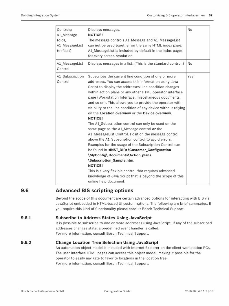
Building Integration System Customizing BIS operator interfaces | en 87
Bosch Sicherheitssysteme GmbH Configuration Guide 2018-10 | 4.6.1.1 | CG
Controls:A1_Message(old),A1_MessageList(default)
Displays messages.NOTICE!The message controls A1_Message and A1_MessageListcan not be used together on the same HTML index page.A1_MessageList is included by default in the index pagesfor every screen resolution.
No
A1_MessageListControl
Displays messages in a list. (This is the standard control.) No
A1_SubscriptionControl
Subscribes the current line condition of one or moreaddresses. You can access this information using JavaScript to display the addresses' line condition changeswithin action plans or any other HTML operator interfacepage (Workstation Interface, miscellaneous documents,and so on). This allows you to provide the operator withvisibility to the line condition of any device without relyingon the Location overview or the Device overview.NOTICE!The A1_Subscription control can only be used on thesame page as the A1_Message control or theA1_MessageList Control. Position the message controlabove the A1_Subscription control to avoid errors.Examples for the usage of the Subscription Control canbe found in <INST_DIR>\Customer_Configuration\MyConfig\ Documents\Action_plans\Subscription_Sample.htm.NOTICE!This is a very flexible control that requires advancedknowledge of Java Script that is beyond the scope of thisonline help document.
Yes
9.6 Advanced BIS scripting optionsBeyond the scope of this document are certain advanced options for interacting with BIS viaJavaScript embedded in HTML-based UI customizations. The following are brief summaries. Ifyou require this kind of functionality please consult Bosch Technical Support.
9.6.1 Subscribe to Address States Using JavaScriptIt is possible to subscribe to one or more addresses using JavaScript. If any of the subscribedaddresses changes state, a predefined event handler is called.For more information, consult Bosch Technical Support.
9.6.2 Change Location Tree Selection Using JavaScriptAn automation object model is included with Internet Explorer on the client workstation PCs.The user interface HTML pages can access this object model, making it possible for theoperator to easily navigate to favorite locations in the location tree.For more information, consult Bosch Technical Support.
88 en | Customizing BIS operator interfaces Building Integration System
2018-10 | 4.6.1.1 | CG Configuration Guide Bosch Sicherheitssysteme GmbH
9.7 Displaying raw OPC dataIntroduction“Raw” fluctuating analog data (integers, floating-point and text) can be displayed in real timein the BIS operator interface using JavaScript. The BIS installation provides two resources tohelp you in implementing this feature in your own operator interfaces:– an example index page containing JavaScript and graphical display widgets from the
public domain.– a demo OPC server to feed values to this index page.This section describes how to set up and run BIS with these resources.
Assigning the example index page to an operator.In order to be used at all, the example index page needs to be assigned to an operator.Prerequisite: A configuration of BIS version 3.0 or higher loaded in the BIS ConfigurationBrowser.1. To create a new BIS operator account click Administration > Operators, and click the +
button above the list of current operators. Give the new operator an appropriate name. If a suitable operator already exists, skip to step 4.
2. Click the new operator in the list of operatorsResult: The General operator settings dialog appears.
3. In this dialog, assign authorization and user profile from the pull-down menus.4. Click the button Manage
Result: The Manage operator profiles dialog appears.5. Set the following value for Default page using the file browser at the end of its input
field.<installation drive>:\MgtS\Customer_Configuration\
<configuration name>\Documents\index_SampleAnalogValues.htm
Notice!index_SampleAnalogValues.htm
This .HTM file contains not only the BIS UI layout with and the example JavaScript code, but
also brief instructions on how to set up this demo.
Setting up the Demo OPC Server to supply analog valuesIn <Installation Drive>:\MgtS\Connections\DemoOPCServer\ do the following:
1. Back up your original DemoOpcServer.xml to a different name e.g.
DemoOpcServer_ORIG.xml
2. Rename SampleAnalogValue_DemoOpcServer.xml to DemoOpcServer.xml
Browsing the Demo OPC serverPrerequisite: The same configuration of BIS version 3.0 or higher loaded in the BISConfiguration Browser.1. Add the OPC server DemoOPCServer as a new subsystem, following the usual browsing
procedure described in Creating connections and addresses by browsing, page 1362. Be sure to add all values to the OPC server and then disconnect the BIS Configuration
Browser from it.
Building Integration System Customizing BIS operator interfaces | en 89
Bosch Sicherheitssysteme GmbH Configuration Guide 2018-10 | 4.6.1.1 | CG
(Optional) Creating a new detector type “StringValue” with new state mappings for thetransmitted stringsAs the purpose of this demo OPC server is to transmit arbitrary, previously unmapped values,there now follows an optional step, the purpose of which is to suppress the error-logmessages that BIS would normally produce in such cases. To do this we map those stringsthat we wish to transmit to BIS onto arbitrary numerical BIS states.Prerequisite: The same configuration of BIS version 3.0 or higher loaded in the BISConfiguration Browser1. Click Infrastructure > Detector types.2. Select DemoOPCServer in the Detector types list and click the New button above it.
Name the new detector type StringValue3. In the State mappings tab, in the lower right corner, click the + button to add a new
state.4. In the ensuing dialog box, select data type string from the Data type list, select radio-
button Single value and enter Test in the text box5. Select an arbitrary state from the list of states and click OK.
Result: The State mappings list receives a new element Test in the Reported states list,6. Repeat the last three steps to add the list elements OPC, Value, Current and Integration
in the State mappings list.7. In the main Detector types dialog, click the Apply button.8. Click Connections > Connection servers. Locate and select DemoOPCServer9. In the BIS addresses (chosen elements) pane, expand the DemoOPCServer tree and
select the address DemoOPCServer.OPCAnalogValue.Demo.Text
10. In the Detector type pull-down menu, set the detector type of the address toStringValue.
11. Click the Apply button.
Notice!Changing the strings in the Demo OPC serverNote that the strings Test, OPC, Value, Current and Integration here are arbitrary strings inDemoOpcServer.xml in the section OPCAnalogValue.Demo.Text. If you change them,
ensure they are changed in both the XML file and Infrastructure > Detector types to avoiderror-log messages.
Running the Demo1. Reload the configuration and open the BIS Client as the operator defined above.2. Click the Subscribe button next to any or all of the analog values that you wish to see in
the BIS Client.P Result: In a continuous loop the scripts in index_SampleAnalogValues.htm display the
values defined in DemoOpcServer.xml
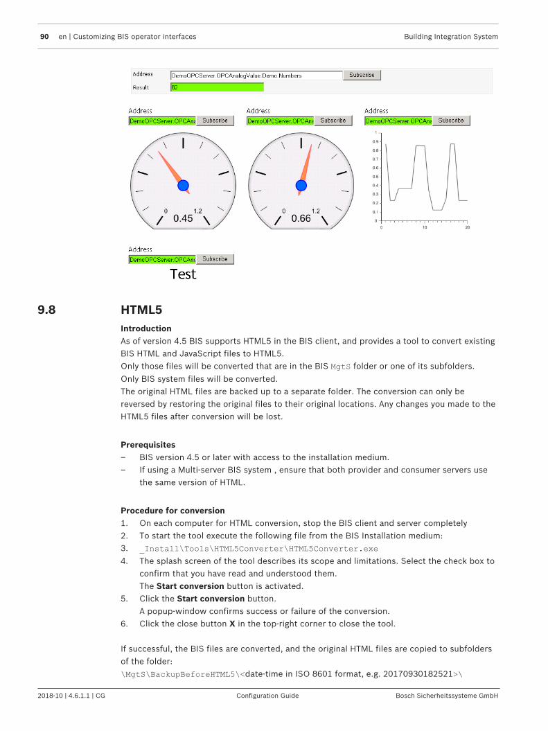
90 en | Customizing BIS operator interfaces Building Integration System
2018-10 | 4.6.1.1 | CG Configuration Guide Bosch Sicherheitssysteme GmbH
9.8 HTML5IntroductionAs of version 4.5 BIS supports HTML5 in the BIS client, and provides a tool to convert existingBIS HTML and JavaScript files to HTML5.Only those files will be converted that are in the BIS MgtS folder or one of its subfolders.
Only BIS system files will be converted.The original HTML files are backed up to a separate folder. The conversion can only bereversed by restoring the original files to their original locations. Any changes you made to theHTML5 files after conversion will be lost.
Prerequisites– BIS version 4.5 or later with access to the installation medium.– If using a Multi-server BIS system , ensure that both provider and consumer servers use
the same version of HTML.
Procedure for conversion1. On each computer for HTML conversion, stop the BIS client and server completely2. To start the tool execute the following file from the BIS Installation medium:3. _Install\Tools\HTML5Converter\HTML5Converter.exe
4. The splash screen of the tool describes its scope and limitations. Select the check box toconfirm that you have read and understood them.The Start conversion button is activated.
5. Click the Start conversion button.A popup-window confirms success or failure of the conversion.
6. Click the close button X in the top-right corner to close the tool.
If successful, the BIS files are converted, and the original HTML files are copied to subfoldersof the folder:\MgtS\BackupBeforeHTML5\<date-time in ISO 8601 format, e.g. 20170930182521>\

Building Integration System Customizing BIS operator interfaces | en 91
Bosch Sicherheitssysteme GmbH Configuration Guide 2018-10 | 4.6.1.1 | CG
Procedure for restoring original HTML files.1. On each computer for rolling back the conversion, stop the BIS client and server
completely2. To start the tool execute the following file from the BIS Installation medium:3. _Install\Tools\HTML5Converter\HTML5Converter.exe
4. The splash screen of the tool describes its scope and limitations. Select the check box toconfirm that you have read and understood them.The Rollback button is activated.
5. Click the Rollback button, and click the Yes button in the pop-up window to confirmA popup-window confirms success or failure of the rollback.
6. Click the close button X in the top-right corner to close the tool.
Before restarting the BIS systemBefore restarting the BIS system after conversion or rollback, clear the local cache of thebrowser. Proceed as follows:1. In the Internet Explorer, go to menu:Tools > Internet options > tab:General2. In the Browsing history pane of the pop-up window, click the Delete… button.3. In the Delete Browsing History pop-up window, select the check box Temporary Internet
files and website files.4. Click the Delete button and close the browser.

92 en | BIS multi-server systems Building Integration System
2018-10 | 4.6.1.1 | CG Configuration Guide Bosch Sicherheitssysteme GmbH
10 BIS multi-server systemsConcepts and overviewFor the main concepts and an overview of BIS multi-server technology, see BIS multi-serversystems, page 11
Notice!Necessity of performance testingPerformance depends on a variety of factors including number of servers, number of records,complexity of records and bandwidth of the network.Bosch urgently recommends that the performance of multi-server installations be thoroughlytested under realistic loads before productive use, and an adequate network infrastructureput in place.
10.1 Providing information to other BIS single server systemsTo provide some or all of the addresses of one BIS single server system to others, it is ofcourse necessary that there be a network connection between them.Secondly the Provider system must create a configuration file that details which addressesshould be provided, that is, visible to and usable by Consumer servers.
Overview of the configuration dialog for Provider servers.The following describes the various parts of the configuration dialog and their functions:
Label Description
Apply button prompts for the name of a (.expcrp) file in which to store the
Provider server’s configuration.

Building Integration System BIS multi-server systems | en 93
Bosch Sicherheitssysteme GmbH Configuration Guide 2018-10 | 4.6.1.1 | CG
Label Description
Three tabs:Filtered addresses tab: For filtering and selecting those addresses that will beincluded in the configuration fileSubscribed addresses tab: For displaying those addresses that have been selectedfor inclusion in to the configuration fileImported addresses tab: For reading addresses from existing configuration filesand adding them to the Subscribed addresses tab
Drop-down list for selecting the subsystems of interest
Check boxes for selecting the detector types of interest
Address filter to further refine the current list of addresses
The current list of addresses of interest, that is, the cumulative effect of (3), (4)and (5) above. When the check box of the address is selected then it appears onthe Subscribed addresses tab
Creating the configuration file for the Provider server
To create the configuration file, proceed as follows:
1. Open the BIS Configuration Browser on the Provider system2. Click Menu: Tools > Remote Site Configuration
Effect: The Remote Site Configuration dialog displays the subsystems, detector typesand addresses currently configured on the Provider system.
3. Select the Filtered addresses tab
4. From the drop-down list select the subsystem whose addresses you wish to provideto consumer servers, or <All> if you wish to provide the addresses of potentially allsubsystems.
5. To the right of the drop-down list, select the check boxes of any detector types you want
to provide , or the superordinate Detector types check box if you wish to providethe addresses of potentially all detector types.Effect: As you proceed, only those addresses belonging to both the selected subsystem
and the selected detector types appear in a list in the main pane of the dialog.Hint: If the list of addresses is still unmanageably long, it may be further reduced by
entering text in the Address filter text box .Note: as yet no addresses have been subscribed, that is, marked for inclusion in theconfiguration file.

94 en | BIS multi-server systems Building Integration System
2018-10 | 4.6.1.1 | CG Configuration Guide Bosch Sicherheitssysteme GmbH
6. Select the check boxes of the addresses in that you wish to offer for subscription,that is, to include in the configuration file.Hint: Use Ctrl-click to toggle the selection of noncontiguous individuals and Shift-click totoggle the selection of contiguous ranges of check boxes.Effect: The selected addresses are listed on the Subscribed addresses tab of this dialog.
7. Click the Apply button 8. Enter a new filename of type .expcrp, or select an existing file to be overwritten.
Effect: The addresses listed in the Subscribed addresses tab of this dialog areexported to the configuration file of type .expcrp.
Hint: Make a note of the location and the file name. The file is required for the configuration ofConsumer systems.
Examining the final list of addresses marked for export to the configuration file4 To get a consolidated list of those addresses that will be exported to the configuration
file, select the Subscribed addresses tab .
Note that once the Apply button has been clicked, and the configuration file created, then thislist will be emptied. You can refill it by:– selecting addresses using the Filtered addresses tab, see Creating the configuration file
for the Provider server or– reading addresses back from existing .expcrp files using the Imported addresses tab,
see Reading and modifying existing configuration files
Reading and modifying existing configuration files
If the configuration of the Provider server changes, for example if OPC servers are added orremoved, then it will be necessary to modify the contents of the existing files.It may be useful to combine addresses from different configuration files into a new file. All this
functionality is provided on the Imported addresses tab .
1. Click the button Read exported addresses from file, and locate an existing .expcrp file
in the pop-up file explorer.Effect: The addresses in the selected file appear as a list in the main pane of the dialog.Note: if any of the addresses in the .expcrp file are no longer configured on the Provider
server, then they will be marked Not Found in the Remark column, and then ignored.2. Click the button Subscribe addresses
Effect: selected addresses are listed on the Subscribed addresses tab of this dialog3. If desired, add further addresses to the Subscribed addresses tab by using the filters on
the Filtered addresses tab. See Creating the configuration file for the Provider server fordetails.
4. Click the Apply button5. Enter a new filename of type .expcrp, or select an existing file to be overwritten.

Building Integration System BIS multi-server systems | en 95
Bosch Sicherheitssysteme GmbH Configuration Guide 2018-10 | 4.6.1.1 | CG
Effect: The addresses listed in the Subscribed addresses tab of this dialog are exportedto the configuration file of type .expcrp.
Hint: Make a note of the location and the file name. The file is required for the configuration ofConsumer systems.
10.2 Consuming information from other BIS single server systemsFor a BIS single server system to become a consumer server, that is to be able to see andprocess information from a remote BIS single server system, also known as a Provider server.It is of course necessary that there be a network connection between them.Secondly you must include the remote system in your configuration. To do this, proceed asfollows:
– Prerequisites: You will need:– the IP address or network name of the Provider server,– network access to the configuration file for that Provider server– the name and password of an operator on the Provider server who has access to the
desired information (e.g. with administrator rights)1. Open the BIS Configuration Browser on the intended Consumer system2. Click Menu: Connections3. Right-click the local machine in the list of connection servers and select Add Subsystem
from the context menu. (Alternatively, left-click the desired server and click the button to add a subsystem to that server)Effect: The Select new subsystem dialog appears.
4. From the list add a subsystem of type Remote Sites Connector , edit the suggestedsubsystem name if desired, and click the OK button.Effect: The Remote Sites OPC server appears below the consumer server as one of itssubsystems.
5. Right-click the new Remote Sites OPC server in the list and select Properties.
(Alternatively, left-click the desired server and click the button to invoke theSubsystem properties dialog.)
6. Click the Launch button to start the external configuration program.Effect: The Configuration of Remote Sites Connector dialog appears.

96 en | BIS multi-server systems Building Integration System
2018-10 | 4.6.1.1 | CG Configuration Guide Bosch Sicherheitssysteme GmbH
7. Click the button to add a BIS Provider server to the list.Note: If no more than one BIS Provider server is to be added select the check box Singleremote BIS server mode.
8. Enter the name of the Provider server or its IP address under column BIS Server. Enterthe name of an operator (on the Provider server) under User, and that operator’spassword under Password.
9. Click the Import… button under column Remote Addresses File and navigate to theencrypted configuration file that you created on the Provider server (see Providinginformation to other BIS single server systems , page 92 ).
10. Click the Save OPC server configuration button.Effect: The current configuration is saved with the selected Provider server as one of itsOPC servers.
11. Click the Exit button to exit the dialog.12. Use the standard browsing procedure as described in Creating connections and addresses
by browsing, page 136 to map the Provider server’s information into the currentconfiguration of this Consumer server.
See also– Creating connections and addresses by browsing, page 136– Providing information to other BIS single server systems , page 92
10.3 Current limitations
There are currently some limitations regarding alarm processing on multi-server BIS systems.
Functionality– Any system information in an Action plan coming from a Provider server relates only to
the Provider server.

Building Integration System BIS multi-server systems | en 97
Bosch Sicherheitssysteme GmbH Configuration Guide 2018-10 | 4.6.1.1 | CG
– Only Action plans defined on the Provider server for a particular address will display onthe Consumer system (server or clients). Action plans defined on the Consumer systemfor the same address (which is a remote address for the Consumer) will not display, evenif the Provider server has no Action plan of its own.
– If an alarm is processed on a Provider server its Action plan links will only appear in theProvider’s event log. If processed on the Consumer server the links appear in both eventlogs.
– Video controls in the Action plan of a remote message are not supported.– Miscellaneous documents for alarms on Provider addresses will not be displayed on
Consumer clients, that is, the Provider does not forward Miscellaneous documents.
Interoperability– Multi-server BIS systems can only operate within a single time zone.– BIS 4.1 and BIS 4.0 systems can not be mixed within a Multi-server BIS system. Bosch
recommends using the latest version wherever possible.– In order to process a message on a consumer system, the operator on the Consumer
system must have the same or more authorizations than the originator on the Providersystem.
Quantitative limitations
Max. number of levels in a multi-server BIShierarchy
2
Max number of Consumer servers perProvider server
1
Max. number of Provider servers perConsumer server
64
Maximum number of Provider servers perRemote Sites Connector
4
Max number of Remote Sites Connectors perConnection server below a Consumer server
4
Max. number of addresses per Remote SitesConnector
10,000
Max. number of alarms per second fromProvider to Consumer server
20
10.4 Upgrading a BIS 4.0 multi-server system
Notice!Multi-Server BIS and customized WCF configurationsIf you have made manual changes to the WCF configuration file:\MgtS\Platform\BisClientProxyWcfServer\BisClientProxyWcfServer.exe.config
in BIS 4.0, these will also be migrated to BIS 4.1 and newer versions. Before customizing thisfile refer to the specialist documentation in \MgtS\Platform\WCF Configuration.pdf

98 en | BIS multi-server systems Building Integration System
2018-10 | 4.6.1.1 | CG Configuration Guide Bosch Sicherheitssysteme GmbH
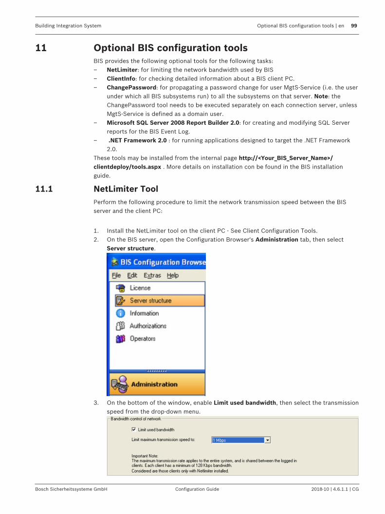
Building Integration System Optional BIS configuration tools | en 99
Bosch Sicherheitssysteme GmbH Configuration Guide 2018-10 | 4.6.1.1 | CG
11 Optional BIS configuration toolsBIS provides the following optional tools for the following tasks:– NetLimiter: for limiting the network bandwidth used by BIS– ClientInfo: for checking detailed information about a BIS client PC.– ChangePassword: for propagating a password change for user MgtS-Service (i.e. the user
under which all BIS subsystems run) to all the subsystems on that server. Note: theChangePassword tool needs to be executed separately on each connection server, unlessMgtS-Service is defined as a domain user.
– Microsoft SQL Server 2008 Report Builder 2.0: for creating and modifying SQL Serverreports for the BIS Event Log.
– .NET Framework 2.0 : for running applications designed to target the .NET Framework2.0.
These tools may be installed from the internal page http://<Your_BIS_Server_Name>/clientdeploy/tools.aspx . More details on installation con be found in the BIS installationguide.
11.1 NetLimiter ToolPerform the following procedure to limit the network transmission speed between the BISserver and the client PC:
1. Install the NetLimiter tool on the client PC - See Client Configuration Tools.2. On the BIS server, open the Configuration Browser's Administration tab, then select
Server structure.
3. On the bottom of the window, enable Limit used bandwidth, then select the transmissionspeed from the drop-down menu.

100 en | Optional BIS configuration tools Building Integration System
2018-10 | 4.6.1.1 | CG Configuration Guide Bosch Sicherheitssysteme GmbH
Notice!The bandwidth limiting function will only work for client PCs with the NetLimiter toolinstalled.
11.2 ClientInfo ToolPerform the following procedure to view client PC configuration information:
1. Install the ClientInfo tool on the client PC - see above.2. The ClientInfo window opens, providing information about the client PC configuration.
3. Click Refresh to update the configuration information displayed in the window.
11.3 Using the ChangePassword toolPurpose and scopeThe ChangePassword tool is used by system administrators to maintain the passwords of BISsystem users, that is both Windows operating system (OS) and SQL users.Examples of system users are:– Mgts-service (OS user)– Mgts-SSRS-Viewer (OS user)– Event log query (SQL user)– Event log writer (SQL user)– Security engine query (SQL user)– Security engine writer (SQL user)
This tool replaces the ChangePassword tool which was formerly downloaded from clienttools, and the SSRS Password Reset tool present in installer folder.Hence those two tools are no longer available
Products concernedBuilding Integration System (BIS) versions 4.6 and later

Building Integration System Optional BIS configuration tools | en 101
Bosch Sicherheitssysteme GmbH Configuration Guide 2018-10 | 4.6.1.1 | CG
Intended audience– Security manager– Software configurer– Software administrator
Usage scenariosConfiguration
PrerequisitesThe BIS system has been successfully installed.
Procedure1. Execute ChangePasswordTool.exe from the folder <BIS installation folder>\Mgts
\Tools\ChangePassword\
2. A welcome screen explains the purpose of the tool. Click Next >3. On the second screen, from the drop-down list Select the user account to change, select
the account that you wish to modify4. In the text box New password, type the desired password5. In the text box Verification, type the desired password again to confirm itIf you are modifying a Windows OS account, or an SQL account with Windows authentication,simply click Set Password.
If you are modifying an SQL account that requires SQL server authentication, proceed asfollows:1. Select the option button SQL server authentication2. Enter the SQL server Login and Password in the text boxes provided3. Click Set Password
Results for MgtS-ServiceIf you changed the password for MgtS-Service:1. The tool displays a list of the Windows services that are affected.
– Click Cancel to abort the changes or Apply to confirm them.2. Proceed with the tool as described in the next section
Results for other passwordsIf you changed a password other than that of MgtS-Service:– The tool confirms whether the requested password change has been successful.
– Click < Back to return to the second screen and set any other passwords that yourequire.
– Click X Exit to close the program.The passwords of SQL users are stored and become effective immediately.The passwords of Windows users become effective only after a reboot.
Important additional information– Do not change BIS user passwords without this tool. Serious malfunctions would result.– Do not delete the file DbUserInfo.crp file. Serious malfunctions would result.
NOTE: If the file has been accidentally deleted, use the tool to create the Mgts-SSRS-Viewer password, and then create all the other SQL users’ passwords with the tool.

102 en | Optional BIS configuration tools Building Integration System
2018-10 | 4.6.1.1 | CG Configuration Guide Bosch Sicherheitssysteme GmbH
– If a remote SQL instance is used, then the tool will update both local machine and alsothe remote SQL machine, prompting for the remote admin username and password ifrequired.
– If SQL reports and SQL event log instances are on two different remote machines, thenensure that both machines have same Windows admin username and password.
– A password that has been changed on a remote SQL instance machine will only come intoeffect after the SQL service has been restarted on the remote instance.
– If connection servers are used, run the tool on each connection server separately, inorder to ensure the same Mgts-Service password throughout.
– Similarly if a multi-server BIS environment is used, run the tool on both the machines(provider and consumer) separately, in order to ensure the same Mgts-Service passwordthroughout.
11.4 Microsoft SQL Server Report Builder 3.0This is a Microsoft tool with its own online help. A white paper is available from BoschSecurity Systems describing in detail how to modify a report for display in the BIS Event Log.Please contact Bosch ST technical support for this white paper.
11.5 .NET Framework 2.0The installation of BIS automatically includes .NET Framework 2.0 on the BIS server, but noton BIS clients, which are typically installed asynchronously. Each BIS client requires .NETFramework 2.0, and so the Framework is always available for installation from the internalpage: http://<Your_BIS_Server_Name>/clientdeploy/tools.aspx .

Building Integration System BIS Manager tabs | en 103
Bosch Sicherheitssysteme GmbH Configuration Guide 2018-10 | 4.6.1.1 | CG
12 BIS Manager tabs12.1 The BIS Manager
Use the BIS Manager to configure and operate the various server functions, and to querysystem statuses. This is done using the following tabs:
– The System Start/Stop tab, page 103– The Transmit Message tab, page 105– The Event log tab, page 105–
– Event log Administrator Settings, page 110– The Backup/Restore Configuration tab, page 112– The Load-Save Configuration tab, page 113– The License tab, page 113– The Error Log tab, page 113– The Version tab, page 114
12.2 The System Start/Stop tab
The Start/Stop system paneThe left side of this tab contains buttons for starting and stopping the BIS server andconfiguration tools (primarily the configuration browser. The right hand side of the tab showsa list of the operators currently logged in, or during startup or shutdown, a list of running,starting or stopping processes.– If the BIS server is currently running, the button is labelled StopServer component— Click
here to shut down the BIS server. The right hand pane shows the progress of theshutdown, process by process. When the server software stops, all operators areautomatically logged out. Use the Transmit message tab to send a message to all logged-in operators, informing them of the planned shutdown.

104 en | BIS Manager tabs Building Integration System
2018-10 | 4.6.1.1 | CG Configuration Guide Bosch Sicherheitssysteme GmbH
– If the BIS server is currently stopped, the button is labelled Start Server component—Click here to start the BIS server manually. The right hand pane shows the progress ofthe startup, process by process. The startup is complete when the round control LED inthe bottom right corner of the window shows green and your operator name appears inthe user list.
Operator listWhen the server software is running, the manager window displays all logged-in operatorswith the IP address of the client PC, the operators' permission levels, and the time theoperators logged onto the system.When a logged in user has been enabled by another user (dual authorization login), the nameof the authorizing user appears in the “Activated by” column.
BIS can also be run as a Windows service (for example, in a server room with nobody loggedonto the system). To configure BIS to run as a service, click Start > Control Panel >Administrative Tools > Services, then right click A1_Proxy_VerWalter and select Properties.Configure Startup type to Automatic.

Building Integration System BIS Manager tabs | en 105
Bosch Sicherheitssysteme GmbH Configuration Guide 2018-10 | 4.6.1.1 | CG
The Configuration pane
In the Configuration pane there is the following button:– Start Configuration program button—Click the Execute Configuration program button to
open the system configuration file and to access the Configuration Browser.
12.3 The Transmit Message tabThe Transmit message tab can be used to send a message to all logged-in users. This maybecome necessary, for instance, if the BIS server is to be shut down for a software upgradeand you wish to request that all users log off.
12.4 The Event log tabUse the Event log tab to read and save the event log, or retrieve existing action plans (whichare logged together with the message in the event log).

106 en | BIS Manager tabs Building Integration System
2018-10 | 4.6.1.1 | CG Configuration Guide Bosch Sicherheitssysteme GmbH
Display Event log SizeThe Event log's size and capacity used are displayed in a graphic. As of BIS version 3.0 themaximum size of the Event log database is 60 GB. Administrator rights are necessary tochange any settings.
Notice!Allocating space to the Event logReducing the size of the event log in the Configuration Browser does not affect how muchspace is allocated on the database server. To reduce the allocated disk space of the SQLserver itself, please use the Enterprise Manager or a similar tool.
Event log data deletion strategyTo ensure that the Event log is always writable it uses the following deletion strategy whennearly full:– When 80% full a warning is generated: "Event log nearly full".– When between 90% and 95% full the event log starts a night job at 01:00 deleting its
oldest data, one day at a time, until at least 10% space has been freed.– When 95% full a warning is generated: "Event log full". The Event log immediately begins
deleting its oldest data, one day at a time, until at least 10% space has been freed.Independently of this, every night the system deletes all entries older than the “Hold-backtime” as defined in:BIS Manager > tab: Event log > button: DB Admin > pane: Hold-back time.
Backing up the Event logThe backup function makes a copy of the Event log, along with action plans and otherdocuments referenced by it.1. In the Backup directory for event log and action plan/miscellaneous documents field,
enter the directory in which to save the event log and action plans. For each backup,choose a uniquely named directory to avoid overwriting an existing event log.
2. Click the Backup button.A popup dialog asks whether the saved data should be removed from the current eventlog.– Click No to save event data to a file in the specified directory.– Click Yes to save the event data as above, but additionally to remove the saved
events from the current event log.
Notice!Data removed and retained in the current Event log by the backup.Backup with data removal deletes all events from the current event log. Structural informationrelated to the events is nevertheless retained, so that the system can continue to use them.
Automatic Backup of the Event logBIS can backup the event log automatically as scheduled by the BIS State Machine.See Example of automatic backup of the event log using Associations, page 183
Restoring the Event log1. In the line Backup directory for event log and action plan/miscellaneous documents
field, click the [...] (file selector) button, then select the directory containing the desiredevent log backup.
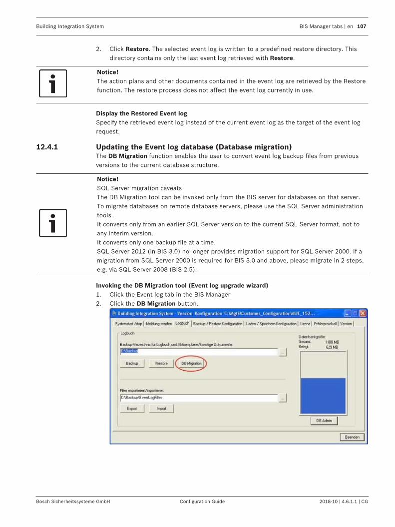
Building Integration System BIS Manager tabs | en 107
Bosch Sicherheitssysteme GmbH Configuration Guide 2018-10 | 4.6.1.1 | CG
2. Click Restore. The selected event log is written to a predefined restore directory. Thisdirectory contains only the last event log retrieved with Restore.
Notice!The action plans and other documents contained in the event log are retrieved by the Restorefunction. The restore process does not affect the event log currently in use.
Display the Restored Event logSpecify the retrieved event log instead of the current event log as the target of the event logrequest.
12.4.1 Updating the Event log database (Database migration)The DB Migration function enables the user to convert event log backup files from previousversions to the current database structure.
Notice!SQL Server migration caveatsThe DB Migration tool can be invoked only from the BIS server for databases on that server.To migrate databases on remote database servers, please use the SQL Server administrationtools.It converts only from an earlier SQL Server version to the current SQL Server format, not toany interim version.It converts only one backup file at a time.SQL Server 2012 (in BIS 3.0) no longer provides migration support for SQL Server 2000. If amigration from SQL Server 2000 is required for BIS 3.0 and above, please migrate in 2 steps,e.g. via SQL Server 2008 (BIS 2.5).
Invoking the DB Migration tool (Event log upgrade wizard)1. Click the Event log tab in the BIS Manager2. Click the DB Migration button.

108 en | BIS Manager tabs Building Integration System
2018-10 | 4.6.1.1 | CG Configuration Guide Bosch Sicherheitssysteme GmbH
3. The first page gives the BIS version and a short introduction to the capability of the tool.Click Next.
Select source and destination filesChanges can be authorized via an SQL Server username and password, e.g. those of the 'sa'user, or via Windows authentication - provided the Windows user currently logged-on hassufficient rights on the SQL Server.1. Click the ellipsis button “...” in the section labeled Source backup file to select the
source file.2. Click the ellipsis button “...” in the section labeled Destination backup file to select the
destination file. NOTE The wizard allows you to save to both local and mapped network drives.
3. Click Next.
NOTE. The wizard gives an error message if it finds the wrong format. Click OK to select adifferent source file.
Progress display4 The next pate shows the steps involved in the DB migration. Click Start to continue.

Building Integration System BIS Manager tabs | en 109
Bosch Sicherheitssysteme GmbH Configuration Guide 2018-10 | 4.6.1.1 | CG
.The following steps are performed:– Checking the space on the current disk drive (min. 10 GB)– Copying the backup file (.bak) to the local drive (in the case of network drives copying
first to a TEMP directory)– Creating a new Event log database with the new structure– Transferring the data– Upgrading the data to the current DB Version (i.e. that of the BIS-Setup)– Backing up the new database– Copying the backup file to back to the network drive (if applicable)– Deleting all temporary and superfluous files and directories
Results displayAfter a successful migration the wizard displays the following:– The number of data records transferred– The number of warnings during the transfer– The execution time

110 en | BIS Manager tabs Building Integration System
2018-10 | 4.6.1.1 | CG Configuration Guide Bosch Sicherheitssysteme GmbH
More information can be found in the log file of the upgrade wizard. To view this click thelink Link to log file
Exporting/importing Event log filters1. Enter a destination directory in the Export/Import filter text box in which to save a pre-
defined event log filter, or the source directory for filters you wish to import.2. Click Export or Import and confirm.
12.4.2 Event log Administrator SettingsOn the Event log tab, click the button DB Admin (below the database size graphic) to changedatabase settings.Changes can be authorized via an SQL Server username and password, e.g. those of thedatabase administrator user, or via Windows authentication - provided the Windows usercurrently logged-on has sufficient rights on the SQL Server.
Notice!You must stop BIS before you can change database settings.

Building Integration System BIS Manager tabs | en 111
Bosch Sicherheitssysteme GmbH Configuration Guide 2018-10 | 4.6.1.1 | CG
Database name and access pathClick the Modify… button next to the text field marked Event log database directory:Enter the new path and filename and confirm to change the location of the database. To backup the event log to a network drive from the BIS login server, the MgtS-service account musthave read/write access to that drive and directory
Database size– Check the size of the database regularly from a client or server workstation.– Back up the event log before the configured size limit is reached and records are lost.– The database capacity can be increased and reduced using this feature. Shrinking the
database size is only possible to the current size minus 10%.– Regardless of whether the user is increasing or reducing the size, they should always
check whether the action completed successfully.
Enter the new database size in the text box. The following restrictions apply:– If MSDE is used then the maximum size that can be entered is 2 GB.– If an Express Edition below 2008 R2 is used, then the maximum size is 4 GB.– If an Express Edition of 2008 R2 or above is used, then the maximum size is 10 GB.– Only if a full SQL server is used can the size be increased above 10 GB.Confirm your input with the OK button at the bottom of the dialog.
PasswordChanging the system administrator username and/or passwordNote: As of BIS 4.6 the database administrator user need not have the username sa. The
database username of any suitably authorized user is acceptable.Procedure1. In the Password pane click the Modify… button.2. Enter the administrator username whose password you wish to change.

112 en | BIS Manager tabs Building Integration System
2018-10 | 4.6.1.1 | CG Configuration Guide Bosch Sicherheitssysteme GmbH
3. Enter the old password, the new password, and the new password again to confirm.4. Click OK to save.
Hold-back time (data retention time)Define here for how long data should be retained in the Event log. The period can be set indays, weeks or months.1. Days
The default period is 30 days. The possible range is 1 to 3650 days. In default case dataolder then 30 days will be deleted on the 31st day.
2. WeeksThe default period is 12 weeks. The possible range is 1 to 530 weeks. Thereafter dataolder than the defined period is deleted on the weekday selected, once per week.
3. MonthsThe default period is 120 months. The possible range is 1 to 120 months. Thereafter dataolder than the defined period is deleted on the first day of the following month
Click OK to confirm your changes.
12.5 The Backup/Restore Configuration tabUse the Backup/Restore Configuration tab to backup or restore the configuration of thesystem or the configuration of the installed products (for example, the Security Engine'sDB9000 database).
1. In the Target Directory field, click the “...” button to select a local or remote directory inwhich to store the backup.
2. Click the Backup button (shown if the system is running) to initiate the backup of thecomponents.
3. Click the Restore button (shown if the system is not running) to initiate the restore of theconfiguration.
Notice!The Backup button changes its label to Restore when the server component has beenstopped from the System start/stop tab.
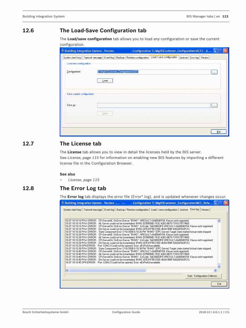
Building Integration System BIS Manager tabs | en 113
Bosch Sicherheitssysteme GmbH Configuration Guide 2018-10 | 4.6.1.1 | CG
12.6 The Load-Save Configuration tabThe Load/save configuration tab allows you to load any configuration or save the currentconfiguration.
12.7 The License tabThe License tab allows you to view in detail the licenses held by the BIS server.See License, page 115 for information on enabling new BIS features by importing a differentlicense file in the Configuration Browser.
See also– License, page 115
12.8 The Error Log tabThe Error log tab displays the error file (Error*.log), and is updated whenever changes occur.
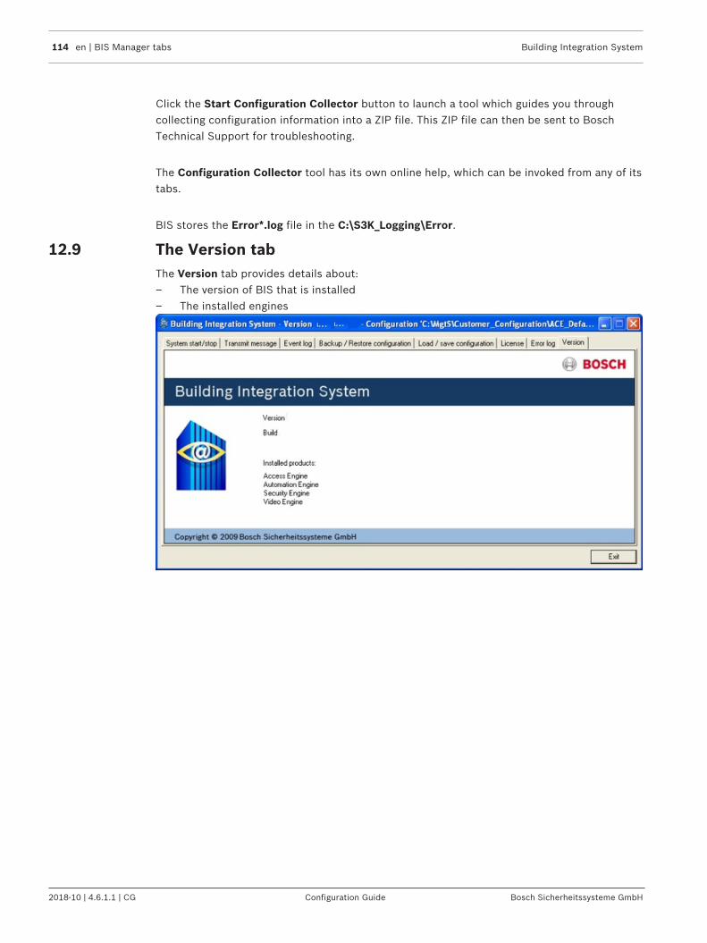
114 en | BIS Manager tabs Building Integration System
2018-10 | 4.6.1.1 | CG Configuration Guide Bosch Sicherheitssysteme GmbH
Click the Start Configuration Collector button to launch a tool which guides you throughcollecting configuration information into a ZIP file. This ZIP file can then be sent to BoschTechnical Support for troubleshooting.
The Configuration Collector tool has its own online help, which can be invoked from any of itstabs.
BIS stores the Error*.log file in the C:\S3K_Logging\Error.
12.9 The Version tabThe Version tab provides details about:– The version of BIS that is installed– The installed engines
Building Integration System Configuration Browser tabs | en 115
Bosch Sicherheitssysteme GmbH Configuration Guide 2018-10 | 4.6.1.1 | CG
13 Configuration Browser tabs13.1 License
The License dialogFrom the Configuration Browser, click the Administration Outlook button, then select theLicense dialog.This dialog shows a list of what BIS features are currently licensed for the currentconfiguration.
Activating licenses for a configuration
Prerequisite: You have activated the licenses for the BIS server that you are using. SeeLicensing the BIS server, page 25 for the procedure to update licenses for the BIS servercomputer, using the BIS manager.1. Open the configuration you wish to modify in the Configuration Browser.2. Click the Administration Outlook button then select the License dialog.3. Click the Read button to refresh the main dialog pane and import the server’s activated
licenses into the current configuration.4. Load or reload the current configuration if you wish the new licenses to take immediate
effect. See Opening (loading), saving and copying configurations, page 35
Notice!Reading ACE licensesOn the Administration Outlook button there is a separate menu for ACE licenses, as theseneed to be read separately.
Demo Mode
For trial purposes it is possible to create proof-of-concept configurations in Demo modewithout a license. Configurations created in Demo Mode can only be run for a limited numberof hours.
Activating Demo Mode
1. From the Configuration Browser, click the Administration Outlook button, then select theLicense dialog.
2. Click the Set button next to the label Demo mode for tests.3. Click OK.4. To apply your settings to the configuration, click the Apply button. If you do not want to
apply your new settings, click the Discard button.
Demo Mode for Access Engine (ACE)Note that, if installed, the BIS Access Engine (ACE) uses its own form of Demo Mode. This canbe activated for ACE configurations in the Configuration Browser by clicking Administration >ACE Licenses > button: Activate Demo Mode.
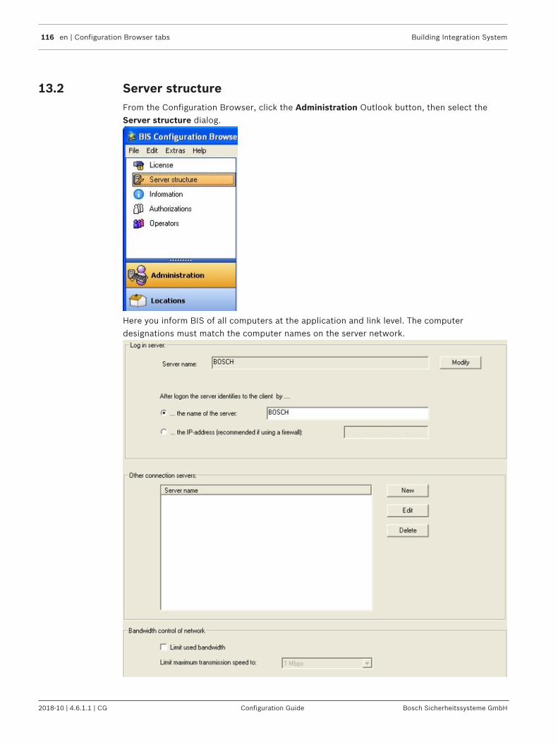
116 en | Configuration Browser tabs Building Integration System
2018-10 | 4.6.1.1 | CG Configuration Guide Bosch Sicherheitssysteme GmbH
13.2 Server structureFrom the Configuration Browser, click the Administration Outlook button, then select theServer structure dialog.
Here you inform BIS of all computers at the application and link level. The computerdesignations must match the computer names on the server network.

Building Integration System Configuration Browser tabs | en 117
Bosch Sicherheitssysteme GmbH Configuration Guide 2018-10 | 4.6.1.1 | CG
1. Define the BIS server the computer to which the client PCs connect. Enter the name ofthis computer in the Server name field. Also choose whether the client PC can identifythe BIS server from its computer name (default setting) or its IP address. If a firewall is used that prevents computer name resolution, choose ... the IP-address(recommended if using a firewall).
Notice!Localhost is not a valid server name - your system will not work correctly.
2. If you need to limit all incoming and outgoing network traffic, check the Limit usedbandwidth check box in the Bandwidth control of network area and select the maximumtransmission speed.
All computers have equal rights. The sequence of the listed computers does not imply ahierarchy. Insert any number of servers in the server structure, but the operator level onlyconnects using the BIS server.
Additional connection serverConnections that are not installed on the BIS server, must also be involved in the BIS serverstructure. These include for example DiBos - and BVMS servers or other locally from the BISserver different connection servers.
Notice!The registered each adding designation (New - Server name) must match the computer nameon the server network, otherwise it will be not recognized during the subsequent browsing ofthe server structure..
Notice!Make sure the compliance of user names from the BIS configuration browser and theconnection servers or change the OPC security settings.
AuthenticationIt is possible to switch from internal BIS authentication to Windows authentication. In thiscase Windows is authenticates the login credentials of operators.A prerequisite is that every BIS operator account must have an identically named Windowsaccount.

118 en | Configuration Browser tabs Building Integration System
2018-10 | 4.6.1.1 | CG Configuration Guide Bosch Sicherheitssysteme GmbH
Notice!Authentication is a system-wide setting, it affects all operators, not just the selected ones!
Click here for more information on: Authentication, page 77
13.3 InformationSelect the Configuration Browser's Administration Outlook button, then click the Informationdialog.
The program version and the version of the configuration data structure are shown here.
You can enter more information on the configuration or about the customer, which can also beprinted out with the configuration.
Any information can be entered, such as:– Name of the customer– General description of the project– Person responsible for the configuration– Version and date of changes– And so on
13.4 AuthorizationsIn the Configuration Browser select Administration > Authorizations.

Building Integration System Configuration Browser tabs | en 119
Bosch Sicherheitssysteme GmbH Configuration Guide 2018-10 | 4.6.1.1 | CG
IntroductionAuthorizations are defined sets of system permissions. They are assigned to operators orActive Directory groups in the following dialogs:Administration > Operators dialogAdministration > Active directory config
Layout of the Authorizations dialog
Procedure for customizing Authorizations
1. Click button New to create and name an Authorization .2. In the main dialog select all the permissions that will be included in it.
The table below explains the permissions that an Authorization may contain3. Click the Apply button to save your changes.
Element Description
Authorized fordivisions
Specifies whether this Authorization is restricted to certainDivisions. If a message is generated within a Division it willonly be seen by operators whose Authorization contains thatdivision. The default Division Common is always selected.

120 en | Configuration Browser tabs Building Integration System
2018-10 | 4.6.1.1 | CG Configuration Guide Bosch Sicherheitssysteme GmbH
Authorized forconfiguration
Defines which configuration pages (Outlook buttons andtheir dialogs in the Configuration Browser) this Authorizationcan access. The default value is UnlimitedClick the Modify... button to create or edit restrictedConfiguration authorizations.
Allowed to terminate system
Determines whether operators with this Authorization mayterminate the BIS system on the BIS server using the BISmanager program.
Allowed to terminate client Determines whether operators with this Authorization mayterminate the BIS client workstation. If this permission is notgranted then the BIS client does not terminate when theoperator clicks the Exit (red “X”) button. Instead a logondialog appears in which the next operator but must log onbefore the first is logged off.
Authorized for fast accesscommand
Selecting this check box allows users at the client PC to usefast access commands. Fast access commands respondimmediately, without presenting the user with a confirmationdialog. See Fast Access command, page 151
Authorization by 2people
Specifies whether dual authorization is required (i.e whethera second operator logon is required to confirm the logon ofsomeone with this Authorization). Click the nearbyAuthorizations button to select those Authorizations whichcan validly confirm this logon.Notice!Dual authorizationapplies only to BIS clients. Logging intothe Configuration Browser and BIS Manager never requiresmore than one username/password pair.
Authorized locationsDefines the locations that operators with this Authorizationmay access. The default is all (no restriction).

Building Integration System Configuration Browser tabs | en 121
Bosch Sicherheitssysteme GmbH Configuration Guide 2018-10 | 4.6.1.1 | CG
Authorized controlsDefines the controls or commands that operators with thisAuthorization can execute. The default is all (no restriction).
Authorized addresslists
Defines the addresses to which operators with thisAuthorization have access. This is done via Address Lists. Forexample, an Authorization could be restricted to receive onlymessages from detectors in the address list Fire.NoteAuthorizations can not be restricted to individual detector-addresses, only to address lists. If an address list is includedin an Authorization, then the BIS Device overview will displayevery one of the list’s detectors to operators with thatAuthorization.
Authorized state listsfor EventLog
Defines the Event log entries to which operators with thisAuthorization have access.This is done via State lists.NoteIn order to prevent retroactive manipulation, entries arewritten along with their authorizations.Limitation: These settings only affect Event log searches andreports, not the visibility of states and messages in theDevice overview or location plans in the BIS client.
See also– Operators, page 124
13.4.1 Setting Authorizations for location nodesIntroductionThe default for Authorized locations when defining new operators is allNevertheless for security reasons it may be desirable to allow different operators differentdegrees of authorization (view, modify, delete) over locations and detectors in the locationtree.By assigning restricted Authorizations to them, Operators can be prevented from receivingalarm messages or displaying location graphics from specific locations.All operators are authorized for the nodes Operators, Detectors without location and Newdetectors. These check boxes are permanently selected.
ProcedureTo restrict the locations for an Authorizations:1. Select the radio button following locations.
A dialog appears in which the entire location tree is displayed,2. Use the check boxes to add or remove locations from the Authorization.
– Selecting a tree node has the initial effect of selecting all its sub-nodes.– Thereafter the check boxes for individual sub-nodes can be cleared and reselected.

122 en | Configuration Browser tabs Building Integration System
2018-10 | 4.6.1.1 | CG Configuration Guide Bosch Sicherheitssysteme GmbH
The BIS-Client displays the new assignment of authorizations in the location tree as follows:

Building Integration System Configuration Browser tabs | en 123
Bosch Sicherheitssysteme GmbH Configuration Guide 2018-10 | 4.6.1.1 | CG
The forms and colors of the location nodes here have the following meanings:
Authorization Appearance in location tree
Node is not authorized. Node is not visible
Main and sub-nodes are authorized. Nodes are dark gray
Main node is not authorized, but some sub-nodes are.
Node is light gray
Main node is authorized, but some of thesub-nodes are not
Main node is dark gray with a red cross.Unauthorized sub-nodes are not visible.
Main node is not authorized. Some of thesub-nodes are authorized and some not.
Main node is light gray with a red cross

124 en | Configuration Browser tabs Building Integration System
2018-10 | 4.6.1.1 | CG Configuration Guide Bosch Sicherheitssysteme GmbH
13.5 OperatorsIn the Configuration Browser select Administration > Operators.
IntroductionOn the tab General operator settings the following settings are made for each operator:– Operator role (Authorization)– Operator profile (customized logon pages for the BIS client)– (Optional) Restrict login to single workstation
Notice!There is no limit to the number of operators in a configuration. However, the license file canset a limit on the number of concurrent users.
Notice!Operator names are limited to 50 characters.The following characters are not allowed: # < > ' " & * ? .The password is case sensitive but the name itself is not.
Operator Role (Authorization)Select an Operator Role, also known as an Authorization.Only one Operator Role can be assigned to each operator.For instructions to create a new customized Authorization see section Authorizations, page 118
Operator profile - defining operator-specific logon screensOperators may log in from different workstations, and these may have a different screenresolutions. A Profile contains a default page plus, optionally, a list of HTML pages withdifferent screen resolutions for different workstations.When the operator logs on to the BIS client, BIS screen resolution of the current workstation,and displays the appropriate page.Procedure to create an operator profile.1. Click the Manage... button
The Manage operator profiles window appears
2. Click the icon to add a new Profile to the list,3. Enter a name for the Profile4. Select a Default page from the file system.
5. If required, click the icon above the table to add resolution-dependent pages– In the table, click the cells to set Screen width, Screen height and Start page– Logon pages are provided in the file system for various operator scenarios, including
use of dual monitor.Logon pages are stored in the directory <INST_DIR>\Customer_Configuration\MyConfig\
For more information on creating logon pages, see section: Creating/Modifying Workstation-Specific Interfaces, page 84

Building Integration System Configuration Browser tabs | en 125
Bosch Sicherheitssysteme GmbH Configuration Guide 2018-10 | 4.6.1.1 | CG
Restricting the operator to a single workstation
If the new operator is to work only from a particular workstation, enter the IP address of theworkstation in the text box IP address.If the new operator is to work only from a particular subnet, enter an IP filter additionally inthe text box IP filter. e.g. 255.255.0.0 where
– a value of 0 represents the parts of the address that may vary, and
– a value of 255 represents the parts of the address that must be the same as in the
text box IP address.In the above example, the operator can log on from any address in the subnet 192.10.*.*.
Operator PasswordsWhen a new operator is set up its password is the same as the operator name.The operators themselves can change their passwords when logging on to the BIS client. Forsecurity reasons it is important to change the default password as soon as possible.An operator with sufficient authorization can set or reset an operator password in theConfiguration Browser.1. In the Configuration Browser main window menu, click: Extras > Change password…2. Enter the operator user name, old password, new password (twice).
Notice!Access Engine operators are configured in a dedicated ACE dialog.Refer to the Access Engine Configuration online help for instructions.
13.6 Audit trailIntroductionThe Audit trail feature in BIS enables operators to investigate changes made to any BISconfigurations on their system. It tracks both changes made in the BIS Configuration Browser,and changes made to files in the configurations’ subfolders, such as miscellaneousdocuments, action plans, floor plans and HTML index pages. It tracks both storedconfigurations and the current runtime folder.The configuration and usage of the Audit trail feature are performed in the BIS ConfigurationBrowser. The feature is not available in the BIS client.The following information can be retrieved from the audit trail database:– On what configuration the change was made– In which BIS menu and screen the change was made– What kind of change was made– When exactly– By which operator– The values of the changed fields, both before and after the change

126 en | Configuration Browser tabs Building Integration System
2018-10 | 4.6.1.1 | CG Configuration Guide Bosch Sicherheitssysteme GmbH
Managing database size.The storage space for Audit trail is limited by the database software.– For SQL Server Express edition 2008 and below the limit is 4 GB– For all other versions of SQL Server the initial limit is also set at 4 GB, but in the
following cases this can be increased in the SQL Server Management software:– For SQL Server Express edition 2008 R2 and above the configurable limit is 10 GB.– For non-Express editions of SQL Server the configurable limit depends only on the
storage hardware.To save storage space, the administrator of the system configures the retention time of theaudit data, and whether the purging of outdated information should be performedautomatically by the BIS system or manually by an operator.When an Audit trail database reaches its size limit it stops trailing changes, and an errormessage is written to the BIS error log.
Notice!Data security risksAudit trail tracks changes to files in BIS configurations without regard to their contents. Usecaution therefore when changing files where sensitive information, such as a password, isstored in plain text, as this information will be transferred as is to the Audit trail database.Workarounds: Avoid altogether using applications which store passwords in plain text, ortemporarily disable the Audit trail feature when making such changes.
13.6.1 Enabling HTTPS for Audit trail (optional)For highly secure environments the use of HTTPS is recommended instead of the defaultHTTP. To configure HTTPS for audit trail, close down the BIS server and BIS ConfigurationManager completely, then perform both the following tasks before restarting them:
Modify the Web.config file1. On the BIS server, navigate to C:\MgtS\Platform\IISRoot\AuditTrailService
2. Rename the file Web.config to Web_default.config.
3. Rename the file Web_https.config to Web.config
Run .BAT files to make registry settings1. From the BIS installation medium, retrieve the file: \Tools\HttpsForBIS
\EnableHttps.bat
2. Run the batch file on the BIS server.Result: Registry settings are adapted from HTTP to HTTPS values.
13.6.2 Configuring the Audit trail featureIn the BIS Configuration Browser click: System > Audit trail configurationResult: The Audit trail configuration window appears– To start trailing configuration changes, select the check box Activate Audit trail.
– Note that this activation itself is recorded in the audit trail as an action for the wholesystem, not just for the current configuration. Therefore, when searching the audittrail for this activation, ensure that the filter is not limited to the currentconfiguration.

Building Integration System Configuration Browser tabs | en 127
Bosch Sicherheitssysteme GmbH Configuration Guide 2018-10 | 4.6.1.1 | CG
– In the text box labeled Records expire after, enter the number of days for which recordsshould be protected from deletion. After this time they will be considered “expired”.
– To reduce storage space for the Audit trail, there are two mutually exclusive options fordeleting expired records:– To start a daily cycle of purging expired records, select the check box labeled
Schedule an automatic purge and enter the time at which the daily purge shouldoccur.
– To purge expired records immediately from the system, click the button Purgeexpired records. Note that this button is not activated if there are no expired records in the system,or if an automatic purge has been scheduled.
13.6.3 Using the Audit trail featureIn the BIS Configuration Browser click: Administration > Audit trail reportResult: The Audit trail report window appears– To search for records in the audit trail, create a filter that matches the records which
interest you, and click the Load/Refresh button. Note that simply clicking the Returnbutton within a filter line does not start the search.– To help you create the filter, permissible input for each cell is displayed at the top of
the filter pane in red, when that cell is selected. NOTE: when entering a date and time, follow the format in the red help text, not theformat seen in the cell.
– Note that filter settings are not saved between sessions. They are discarded uponclosing the BIS Configuration Browser.
– A filter may consist of between 1 and 6 conditions on separate lines. Note: All the conditions are combined by a logical AND.– To add conditions to the filter, click the [+] button .
Result: A new line appears.– To remove a condition from the filter. Click in the undesired filter line and then click
the [X] button . Result: The selected line is removed.
– Click the Reset button to discard the current filter settings.
Audit-trail filter-columnsThe following table gives detail about what you can enter in the different filter columns:
Column name Description of contents
1 Configuration The path and name of the configuration that was changed.
2 Menu The main BIS menu (Administration, Locations, Connections etc.)where the change was made.Alternatively the words File Audit for a change made to a configurationfile outside of the BIS Configuration Browser.
3 Screen name The BIS sub menu below the main menu where the change was made.For example, in the case of menu Administration, the screen names areInformation, Authorizations, Operators etc.

128 en | Configuration Browser tabs Building Integration System
2018-10 | 4.6.1.1 | CG Configuration Guide Bosch Sicherheitssysteme GmbH
Column name Description of contents
4 Operator The BIS operator that made the change, or System if changes weremade outside of the BIS Configuration Browser, for example: filesdeleted in the Windows file system.
5 Date and Time The date and time that the change was made.Use the date and time formats that appear in red at the top of thedialog window.You may use the SQL function @TODAY or @TODAY-N (where N is an
integer between 1 and 99)
6 Action One of ADD, MODIFY, DELETE
7 Field NOTE: This column is read-only, and cannot be used to create filters.For each record in the audit trail the column Field is divided intoseparate lines.The number of lines depends on the complexity of the change, that is,how many input fields were involved.
8 Old value The previous values of the objects listed in the Field column of thisaudit record.
9 New value The changed values of the objects listed in the Field column of thisaudit record.
Navigating in the search resultsAbove the table of search results a toolbar provides the following functions for navigatingthrough the results:– Arrow buttons to scroll one page back or forward, or else go to the first or last page.– A text window to enter the desired page number.– A pull-down menu to set the size of the font.– A text window for finding strings within the results. Enter a string to seek and click Find
to start a new search, or Next to find the next occurrence of the current string.– A button to refresh the search results– A button to print the search results.
Exporting the search results to common file formatsAbove the toolbar two controls provide a way of exporting the search results into common fileformats:1. In the pull-down menu, select the file format, for example: PDF, Excel or Word2. Click the Export button to export the search results to the chosen file format.3. You will be prompted for a location in which to save the file.
Notice!Restrictions on cell contents in ExcelExcel restricts the contents of any cell to 32767 characters. In the unlikely event that an audittrail export exceeds this limit, an error message is produced and you will not be prompted foran Excel file name. Full details are written to the BIS error log.Note that exports to PDF and Word will still be possible.

Building Integration System Configuration Browser tabs | en 129
Bosch Sicherheitssysteme GmbH Configuration Guide 2018-10 | 4.6.1.1 | CG
13.6.4 Audit trail performanceDue to the large number of files to copied, the performance of the Audit trail feature isadversely affected by the creation, loading and unloading of whole configurations.If such major changes have been planned and documented elsewhere, you may wish toconsider temporarily deactivating the Audit trail feature at these times.
See also– Configuring the Audit trail feature, page 126
13.7 DivisionsIf a site monitored by one BIS system is occupied by two or more autonomous entities (e.g.companies, tenants, divisions) then it may be advantageous to, divide the site into separatedivisions and assign different operators to each. These operators will only see events,locations, card holders etc. for their own divisions. The Divisions feature is licensedseparately. If not licensed then all locations belong to a default division, called Common.
Notice!Configuration changes of DB9000 are always logged and visible to all operators - regardless oftheir divisions.
From the Configuration Browser, click the Locations Outlook button, then select Divisions.
Use this screen to create, edit, and delete the configuration's divisions. If Access Engine (ACE)is configured, the ACE device editor automatically receives the division data. For moreinformation, refer to the BIS Access Engine Configuration online help.
– To create a new division, click .
– To delete a division, click on the division to select it, then click .
Notice!The Divisions feature is licensed separately.Division names are limited to 50 characters.The following characters are not allowed: # < > ' " & * ? .

130 en | Configuration Browser tabs Building Integration System
2018-10 | 4.6.1.1 | CG Configuration Guide Bosch Sicherheitssysteme GmbH
Color mappingsColor mappings provide a simple way of telling which locations belong to which divisions. Thecolors in the color column are reflected later in the configuration's location tree.In order to select or modify the color, click the color-selector button in the respective row ofthe color column.
In the Divisions dialog... In the Tree Structure dialog...
13.8 Tree structureThis dialog is where the configurator defines the hierarchy of the locations and other objectsmonitored by the system. For example, a site may contain buildings, which may in turn containfloors, which contain rooms etc. This dialog is where the configurator associates auxiliary filessuch as floor plans, action plans and miscellaneous documents with the location tree.
Click Outlook bar: Locations > Tree Structure. The following dialog appears. The variouspanes in the dialog are described in the table below.

Building Integration System Configuration Browser tabs | en 131
Bosch Sicherheitssysteme GmbH Configuration Guide 2018-10 | 4.6.1.1 | CG
Picturetag #
Description Purpose
1 Location tree pane Adding, modifying and deleting objects in the locationhierarchy.
2 Location tree graphic Shows the hierarchical structure
3 Graphic file pane Shows the name of the current floor plan (default:logo.dwf), and the current layer in that floor plan (default:INITIAL)
4 Layer pane Selects which layer of the floor plan is to be associatedwith the currently selected location in the tree graphic (2)
5 Documents pane Selects which action plan or miscellaneous document is tobe associated with the currently selected location in thetree graphic (2), and when (under which state) thedocument is to be displayed to the operator.
6 Automatic documentprinting pane
Selects which documents are to be printed automatically,and when (under which state).
You may assign each node of the location tree to a graphic file (for example, a floor plan) or anamed section within a graphic file (for example, a room in the floor plan). By default, the fileLogo.dwf and the named section INITIAL are assigned.

132 en | Configuration Browser tabs Building Integration System
2018-10 | 4.6.1.1 | CG Configuration Guide Bosch Sicherheitssysteme GmbH
Organization of auxiliary files the Location TreeFloor plans, action plans and miscellaneous documents are stored in the appropriatesubdirectory of <INST_DIR>Customer_Configuration\MyConfig\Documents
Directory Description
...\Documents\Floor plans For floor plans, layers, name sections of floor plans, detectorhyperlinks, and so on.
...\Documents\Actionplans
For action plans.
...\Documents\Printouts For all other documents to be displayed in addition to thelocation plan (for example, dangerous substance information,first aid instructions, and so on).
13.8.1 Building the Location Tree1. Add elements to the tree in the normal BIS way: First, if the Divisions feature is licensed,
select the desired division from the combo box. Then select the “parent” branch in thetree to which you wish to add a sub-branch, then click the New button.
2. Change the order of a node within the tree by first selecting it and then clicking the arrowbuttons to the right of the tree.
13.8.2 Assigning graphic files and their layers to nodes in the location treeTo assign graphic files (e.g. floor plans) to nodes in the location tree, proceed as follows.1. Browse for the desired file using the “...” button in the Graphic file pane. The file name
then appears in the associated text box.2. Click the Scan graphic file button in the Graphic file pane. If this graphic file has not
been scanned before, and it contains named views that should correspond to sub-locations in the location tree, then select the check box A new sub location willautomatically be created for every named view in the pop-up dialog, and click the Startbutton. BIS then creates the appropriate nodes in the location tree automatically. You canadjust the relative positions later using the arrow buttons beside the location tree.– Note: If the graphic has changed since last using this dialog, click the Scan graphic
file button to re-scan the graphics file.
– If the naming conventions in the graphic file and in BIS are the same, then BISautomatically assigns the named sections (for example, individual rooms on a floor)to the appropriate locations. For more details, see Configuring location plans (floorplans), page 77

Building Integration System Configuration Browser tabs | en 133
Bosch Sicherheitssysteme GmbH Configuration Guide 2018-10 | 4.6.1.1 | CG
3. In the Layer pane, click the Modify... button to invoke the Selection of layers dialog. Torestrict the display of a graphic file layer (left pane) to a particular location or a particularstate, then select the respective radio button labeled at the following locations (middlepane) or at the following states (right pane).Alternatively, select the always radio button above the respective column, if the layer isto be displayed at all locations or at all states.
4. Click OK to save the changes.
Example of Using LayersThe graphic for the alarm location “Savings Bank Ground Floor” contains the following layers:– Escape route Sun Street– Escape route Station StreetIf the message “Robbery” is in process for a detector from the “Sun Street” alarm area,whenever the location “Savings Bank Ground Floor” is selected, the escape route layer forStation Street should display.Else, for every robbery message from the “Station Street” alarm area, the escape route layerfor Sun Street should display.
Required entries and assignments in the configuration:
Layer Alarm Location Status
Escape route Station Street Sun Street Robbery
Escape route Sun Street Station Street Fire
13.8.3 Assigning action plans and miscellaneous documents to nodes in thelocation treeTo assign other html documents (e.g. action plans and miscellaneous documents) to nodes inthe location tree, proceed as follows. Note: An alarm message can display only one actionplan,
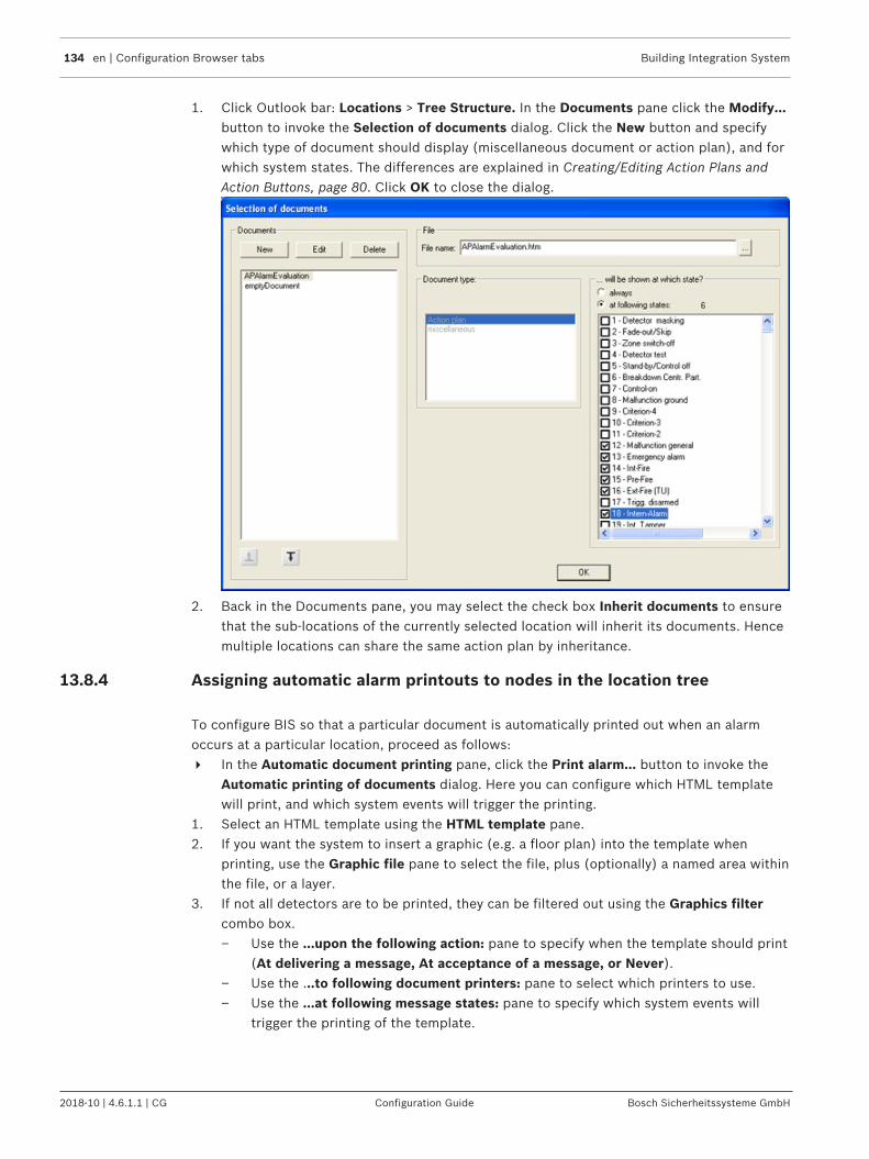
134 en | Configuration Browser tabs Building Integration System
2018-10 | 4.6.1.1 | CG Configuration Guide Bosch Sicherheitssysteme GmbH
1. Click Outlook bar: Locations > Tree Structure. In the Documents pane click the Modify...button to invoke the Selection of documents dialog. Click the New button and specifywhich type of document should display (miscellaneous document or action plan), and forwhich system states. The differences are explained in Creating/Editing Action Plans andAction Buttons, page 80. Click OK to close the dialog.
2. Back in the Documents pane, you may select the check box Inherit documents to ensurethat the sub-locations of the currently selected location will inherit its documents. Hencemultiple locations can share the same action plan by inheritance.
13.8.4 Assigning automatic alarm printouts to nodes in the location tree
To configure BIS so that a particular document is automatically printed out when an alarmoccurs at a particular location, proceed as follows:4 In the Automatic document printing pane, click the Print alarm... button to invoke the
Automatic printing of documents dialog. Here you can configure which HTML templatewill print, and which system events will trigger the printing.
1. Select an HTML template using the HTML template pane.2. If you want the system to insert a graphic (e.g. a floor plan) into the template when
printing, use the Graphic file pane to select the file, plus (optionally) a named area withinthe file, or a layer.
3. If not all detectors are to be printed, they can be filtered out using the Graphics filtercombo box.– Use the ...upon the following action: pane to specify when the template should print
(At delivering a message, At acceptance of a message, or Never).– Use the ...to following document printers: pane to select which printers to use.– Use the ...at following message states: pane to specify which system events will
trigger the printing of the template.

Building Integration System Configuration Browser tabs | en 135
Bosch Sicherheitssysteme GmbH Configuration Guide 2018-10 | 4.6.1.1 | CG
Notice!The graphic appears on the printed HTML page at the position defined by the HTML “IMG”tag.To print using the HTML template assigned to the currently selected location, click the Newdefault document printout with graphic button. This automatically enters the defaulttemplate for manual printing, the current graphics file with the named section, and theselected layers.The HTML page can contain macros, which are instantiated before printing.Click here for more information on action plans: Creating/Editing Action Plans and ActionButtons, page 80
13.9 Connections and Addresses
Notice!
Changes made here are recorded in the Event Log
13.9.1 AddressesConnections may be understood as subsystems that communicate with the BIS system. Eachsubsystem contains devices, each of these devices may contain detectors and each of thesemay contain different sensors. Every item in this hierarchy that can give a signal is identified tothe system by a unique address. The assignment of addresses is therefore essential to thefunctioning of BIS.– Most commonly addresses are assigned by browsing (see Creating connections and
addresses by browsing, page 136 below)

136 en | Configuration Browser tabs Building Integration System
2018-10 | 4.6.1.1 | CG Configuration Guide Bosch Sicherheitssysteme GmbH
– Addresses can be also assigned individually by hand, or generated en masse for relatedobjects using dialog boxes. The Configuration Browser offers different dialog boxes forthe creation of connections, depending on the nature of the connection. E.g. firedetectors have different address requirements from cameras, door controllers or burglaralarms.
13.9.2 Creating connections and addresses by browsingThe following is the usual and most convenient procedure to create a connection from BIS to asubsystem. It is commonly referred to as “browsing” a connection.1. In the Configuration Browser, select the Connections Outlook button.
2. Right-click the connection server, then select Add Subsystem...

Building Integration System Configuration Browser tabs | en 137
Bosch Sicherheitssysteme GmbH Configuration Guide 2018-10 | 4.6.1.1 | CG
3. On the left side of the Select new subsystem window, select the type of OPC server toadd.
4. If you have installed a new OPC server while the Configuration Browser was running,press Refresh to scan again for OPC servers.
5. Type a name in the Subsystem name field, or modify the default name if desired.6. If available, the name of the appropriate OPC configuration program will appear under
Launch external configuration program. If one exists but none has been found, click theopen-folder icon to browse for it.
7. Click OK to close the Select new subsystem window.8. At the top of the OPC server (available elements) pane, click Connect to find the OPC
server on the network.
9. Result: The OPC server appears in the OPC server (available elements) pane.

138 en | Configuration Browser tabs Building Integration System
2018-10 | 4.6.1.1 | CG Configuration Guide Bosch Sicherheitssysteme GmbH
10. Click the [+] nodes in the hierarchy to explore the namespace of the OPC server
11. Right-click the topmost elements and select Add all itemsor alternatively -- Right-click each OPC server element that you want to add to the configuration, thenselect Add Node from the context menu. Result: The selected nodes appear in the BIS Addresses (Chosen Elements) pane

Building Integration System Configuration Browser tabs | en 139
Bosch Sicherheitssysteme GmbH Configuration Guide 2018-10 | 4.6.1.1 | CG
12. (For BIS 4.1 and higher) Use the field Description or URL of associated camera for abrief text description of the detector.
Alternatively you can enter the URL of a camera in the vicinity of the detector, in theformat:http://CAMERA-IP-ADDRESS?type=VSDK&VRM=VIDEO-REC-MGR-IP-ADDRESS e.g.http://172.31.23.80?type=VSDK&VRM=172.31.23.0– Effect: If the detector raises an alarm state that is recognized by the event log, then
the record in the event log will contain links to this camera or cameras. Clicking onsuch a link will retrieve archived recordings from that camera for the time of thealarm.
13. Use the Detector Type drop-down menu to identify the element's type.14. When you have finished adding elements, click the Apply button.15. Click the Disconnect button to stop browsing for the OPC server on the network.
Click here for more information on OPC connections in general: OPC classic connections,page 45
Notice!The following characters are not allowed: # < > ' " & * ? .
13.9.3 Disabling / Enabling connectionsAlongside every connection is a check box that allows you to disable and enable it temporarilyfor testing purposes without the need to browse and re-configure the OPC server.
Notice!Remember to re-enable these connections after testing, else they will remain unavailable tothe system.
13.9.4 Reloading OPC connectionsThere are typical occasions when it may be necessary to refresh definitions and assignmentsin BIS with updated definitions and mappings from an OPC Server.– You wish to undo manual changes made within BIS, and restore the BIS configuration to a
previous state– The OPC Server has been updated or reconfigured, and you wish to take advantage of
this update in BIS– After adding a BVMS OPC Server connection.

140 en | Configuration Browser tabs Building Integration System
2018-10 | 4.6.1.1 | CG Configuration Guide Bosch Sicherheitssysteme GmbH
Reloading is easily achieved via the context menu (right-click on node) in the BIS addresses(chosen elements) explorer pane. The reload affects only the selected node and its children.Prerequisites are that the relevant OPC Server be connected and its node expanded in theOPC server (available elements) pane.
The following table summarizes the relevant context menu choices and their usage.
IF you wish to… THEN right-click the BISnode from which point downyou wish to make thechange, and select:
Effect
Undo changes to addressdescriptions made manuallywithin the configuration.
Get all descriptions fromserver (Get description fromserver)
Overwrites the addressdescriptions within theconfiguration with thosedefined by the OPC Server.
Load address descriptionswhich have changed withinthe OPC Server (new version,different configuration, …)
Undo changes to detectortype definitions mademanually within theconfiguration.
Get detector typesdefinitions from server
Overwrites the detector typedefinitions within theconfiguration with thosedefined in the OPC server.
Load detector typedefinitions which havechanged within the OPCServer (new version, differentconfiguration, …)
Undo changes to detectortype assignments mademanually within theconfiguration.
Get all detector types fromserver (Get detector typefrom server)
Overwrites the detector typeassignments of each addresswithin the configuration withthose defined by the OPCServer.

Building Integration System Configuration Browser tabs | en 141
Bosch Sicherheitssysteme GmbH Configuration Guide 2018-10 | 4.6.1.1 | CG
Load all detector typeassignments which havechanged within the OPCServer (new version, differentconfiguration, …)
Undo changes made manuallyto URLs within theconfiguration.
Get all URL target devicesfrom server (Get URL targetdevice from server)
Overwrites the URLdefinitions of each addresswithin the configuration withthose defined by the OPCServer.
Load URLs which havechanged within the OPCServer (new version, differentconfiguration, …)
Notice!The first time a BVMS connection is added it is necessary to invoke Get detector typesdefinitions from server from the context menu.
13.10 Detector placementIntroductionA BIS configuration stores all known devices in its Device Tree, and all known locations (areas,sub-areas) in its Location Tree (“Tree structure”). If you want to make full use of the locationgraphics extension to BIS, then it is necessary to create an interactive mapping between thedevice and location trees on the one hand, and the hyperlinks and sub-areas respectively inthe location graphics.BIS offers considerable support in creating this mapping, and that is the subject of thissection.
Detector placement prerequisites– You must have already created a location tree, see Tree structure, page 130– You must have defined the required detectors with their respective types and preferably
assigned symbols to them.– (If using location plans) you must be in possession of an AutoCAD location graphic in
DWF or HSF formats. The graphic file should contain hyperlinks to the addresses ofdetectors. It may also contain named sub-areas, also known as named sections or namedviews.
Select the Configuration Browser's Locations Outlook button, then click Detector placement.

142 en | Configuration Browser tabs Building Integration System
2018-10 | 4.6.1.1 | CG Configuration Guide Bosch Sicherheitssysteme GmbH
Procedure for mapping detector-addresses to locationsOptimally the producer of the graphic file should use the same naming scheme for sub-areaswithin it as has been used in the location tree within BIS. Likewise there should be in thegraphic file hyperlinks whose names match the addresses in the device tree. If this is the case,then BIS is able to create interactive mappings between hyperlinks and detector-addresses onthe one hand, and between sub-areas and BIS locations on the other.

Building Integration System Configuration Browser tabs | en 143
Bosch Sicherheitssysteme GmbH Configuration Guide 2018-10 | 4.6.1.1 | CG
Notice!Consequently, the producer of the graphic file must not give to a hyperlink the name of alocation instead of the address of a detector. This would create an unusable mapping withinBIS, and would have to be removed by deleting and re-creating the hyperlink.Instead, always associate by name:Hyperlinks in the graphic with device addressesandSub-areas in the graphic with locations in the BIS location tree.
The mapping of detector-addresses to locations proceeds differently depending on thescenario, i.e. on whether a graphic file exists at all, and if so, on the naming scheme of theelements within it.
Scenario Action Procedure
Either there is nographic file available,or else no hyperlinksor sub-areas arepresent in theAutoCAD graphics.
Manualmapping ofaddresses tolocations
From the device tree, choose the appropriate unitsand addresses, and drag&drop them to the desiredlocation in the location tree.This is can be done with multiple selections also.
In the AutoCADgraphic, the samenaming scheme hasbeen used forhyperlinks that wasused for detectors inthe BIS configuration.
And the same namingscheme has beenused for sub-areasthat was used forlocations in the BISconfiguration.
Automaticmapping ofaddresses tohyperlinks
Click the Scan graphic button. The scanning processseeks to maps the hyperlinks in the graphics to BISdetectors of the same name.
A popup window appears with the following options:All named views of the graphic will be checked (forall sub locations of ‘New detectors’) Select this check box to scan the graphic file foritems in named views (sub areas) within the graphic.If an item occurs in two overlapping named views,then the first named view to be scanned gets theitem. Changes can be made manually later.
The names of the devices (before the group name)are contained in the links.Select this check box if the same naming schemehas been used within BIS and in the graphic file, andBIS should attempt an automatic mapping.
In links the following will be used as a separator[ . ] If a different separator character has been used inthe graphic’s hyperlink names from the standard “.”separator in BIS, then it can be entered here, to helpBIS achieve the mapping.E.g. Hyperlink IPCamera/1 can be mapped to BISaddress IPCamera.1.
Existing links will be overwritten

144 en | Configuration Browser tabs Building Integration System
2018-10 | 4.6.1.1 | CG Configuration Guide Bosch Sicherheitssysteme GmbH
Scenario Action Procedure
Select this check box if the graphic has changedconsiderably, and the previous mappings ofaddresses and hyperlinks are no longer valid.Clear this check box if only minor additions are to bemade.
After using Scangraphic there are stilldetector addressesmissing next to thehyperlinks in the listwindow (pane:Mapped detectors oflocation. > tabHyperlinks of thegraphic.)
Manualmapping ofaddresses tohyperlinks
Select the desired detector or detectors from tree inthe Devices pane, or one of its sub-panes (Groups,Detectors, Sensors). Drag and drop them onto thecorresponding hyperlinks in pane: Mappeddetectors of location. > tab Hyperlinks of thegraphic.
Notice!The following characters are not valid within location links: & <> ‘ “
13.10.1 Controlling layer visibility through statesIntroductionBIS can be configured to display or hide a layer of a location plan depending on the currentstate of a BIS address.The visibility of one graphic layer can be made dependent on only one address, but on anycombination of states valid for that address.The configuration procedure is described in this section.
PrerequisitesA location plan has been created in the configuration.At least one layer other than layer 0 has been created within the location plan.A BIS address (usually a detector) has been anchored on layer 0 via a hyperlink.
Enabling and disabling Layer visibility by stateBIS provides batch command files to enable, disable and check the current setting of thisfeature. The batch files are located on the BIS installation medium at the following paths:_install\Tools\LayerControlByStatesActivation\EnableFeature.bat
_install\Tools\LayerControlByStatesActivation\DisableFeature.bat
_install\Tools\LayerControlByStatesActivation\DisplayFeatureStatus.bat
Notice!Precedence of Alarms and States in deciding layer visibilityBy default in BIS, alarms take precedence over states in deciding the visibility of a graphiclayer. Enabling the feature implicitly reverses this priority, so that states take precedenceover alarms.

Building Integration System Configuration Browser tabs | en 145
Bosch Sicherheitssysteme GmbH Configuration Guide 2018-10 | 4.6.1.1 | CG
Procedure in the Configuration Browser1. Open the dialog Locations > Detector placement2. In the dialog pane Mapped detectors of location click the button Layer and states
The dialog Layer and states opens3. In the Layer pane of the Layer and states dialog, select the layer whose visibility is to be
controlled4. In the Mapped address pane, select the device that is hyperlinked to layer 0 of the
graphic5. In the …shown at state pane, select the check boxes of all those states that are to cause
the layer to appear.6. Click OK to save.7. Upon return to the Locations > Detector placement dialog click Apply8. Save and load the configuration.
Testing layer visibility in the BIS Client1. Restart the BIS client with the modified configuration.2. In the BIS client, load the layered graphic in the Document Display Area.3. Verify that the mapped layer is not currently displayed.4. In the graphic or in the Device overview right-click the detector whose states you have
mapped to a graphic layer.5. In the parameters dialog enter the number of one of the states that is mapped to the
layer.6. Verify that the layer appears in the graphic.7. Right-click the same detector in the graphic.8. In the parameters dialog enter the number of a state that is not mapped to the displayed
layer.9. Verify that the graphic layer disappears from the graphic.
Limitations and restrictionsThe following restrictions currently apply to controlling layer visibility by state.– Map a detector address to only one graphic layer. Nevertheless any combination of states
of the address can be used.– Use only detector addresses that are defined as hyperlinks on layer 0 of the graphic.
– Detectors directly at location are not supported.– Ensure that layer 0 is always visible.– In order to assign a different graphic file to a detector address, delete and re-create the
detector.– Delete and re-create the entire layer/state mapping if you remove layers or links from a
graphic file.– After replacing a graphic file in a BIS location, re-scan the graphic file. Click the buttons
– Locations > Detector placement > Scan graphic file and– Locations > Tree structure > Scan graphic file
13.11 StatesA state is the condition of a detector. In rare cases it may make sense to create new states,but BIS offers a large number of predefined states to choose from.
From the Configuration Browser, click the Infrastructure Outlook button, then select States.

146 en | Configuration Browser tabs Building Integration System
2018-10 | 4.6.1.1 | CG Configuration Guide Bosch Sicherheitssysteme GmbH
Use this screen to tell BIS which line states to use, and specify:– Which priority a particular state has (0 to 99)– How, in the event of a message, the state is presented on the user interface (foreground/
background colors, sound file to be played)– The text name of state
Notice!The overview dialog offers the predefined states 0 to 4999 and 9999 (“Welcome”).With the exception of 9999 these can not be modified.New states can be created within the range 5000 to 9998.It is not possible to reassign a newly created state (> 4999) into the range of predefinedstates (< 5000).

Building Integration System Configuration Browser tabs | en 147
Bosch Sicherheitssysteme GmbH Configuration Guide 2018-10 | 4.6.1.1 | CG
States dialog overview
The numbered labels (1) through (5) are described in the sections below.
States (1) and State Lists (2)
Use the State lists section of the screen to combine states into groups. This simplifies thewriting of Associations by allowing them to react to different states in the same way. Forexample: to switch on a backup device whatever malfunction occurs in the original device.From the State List combo box you can select existing lists.
You can create New lists and states, Rename existing lists and states or Delete them.On the user interface, use state lists, for example, to filter detectors on the location graphic.

148 en | Configuration Browser tabs Building Integration System
2018-10 | 4.6.1.1 | CG Configuration Guide Bosch Sicherheitssysteme GmbH
Notice!If states are needed in e.g. Associations, the number of states can be smaller than the totalstates known to BIS. This will be the case, if a state mapping had been defined in theDetector Type definition.
State Lists Table
All State lists appear in the state lists table.– Click in the heading of a column to sort them in ascending or descending order.– Click New in the State lists area to create a new state list.– Click New in the States area to create a new state.– You can also Rename and Delete state lists and states.
– Click to change a state's text color.
– Click to change a state's background color.
– Use the buttons to play, stop, delete, or select a sound file that will playwhen BIS detects the state.
Notice!The following characters are not allowed for States or State Lists: # < > ' " & * ? .
Malfunction states and supervision addresses (4)Use the Malfunction states combo boxes to define how BIS signals OPC server and detectorfaults.For many individual OPC devices it is possible to designate one of the addresses as asupervision address, i.e. one that signals only whether or not the device is malfunctioning (ordisconnected). This is done by selecting the check box labeled signals device malfunction (orequivalent wording depending on the OPC server) when defining the state. The BIS statemachine monitors supervision addresses especially and responds to them as defined in thesecombo boxes:
Combo box labeled: Description
Malfunction of system If the state you select here occurs on one of the designatedsupervision addresses then ...
Malfunction of detectors ... all the detectors of the same OPC device are set to thestate you select here.

Building Integration System Configuration Browser tabs | en 149
Bosch Sicherheitssysteme GmbH Configuration Guide 2018-10 | 4.6.1.1 | CG
Notice!The BIS state machine takes account of supervision addresses when processing Associations:If, for example, an address goes into a state X that triggers an Association, and if that addresssignals the same state X after having signaled a malfunction on the supervision address in themeantime, then the BIS state machine recognizes that state X was the last valid state beforethe malfunction, and does not trigger the Association again for the same address.For more details on defining Associations see General procedure for configuring Associations,page 178
Audio file (5)The audio file associated with this state is played when BIS detects the state.Here you will find information on the size and transmission time of the audio files used.
13.12 Detector typeIn the Configuration Browser, select the Infrastructure Outlook button, then click Detectortype. In addition to the standard detector types already available in the system, you can set upany number of new detector types.
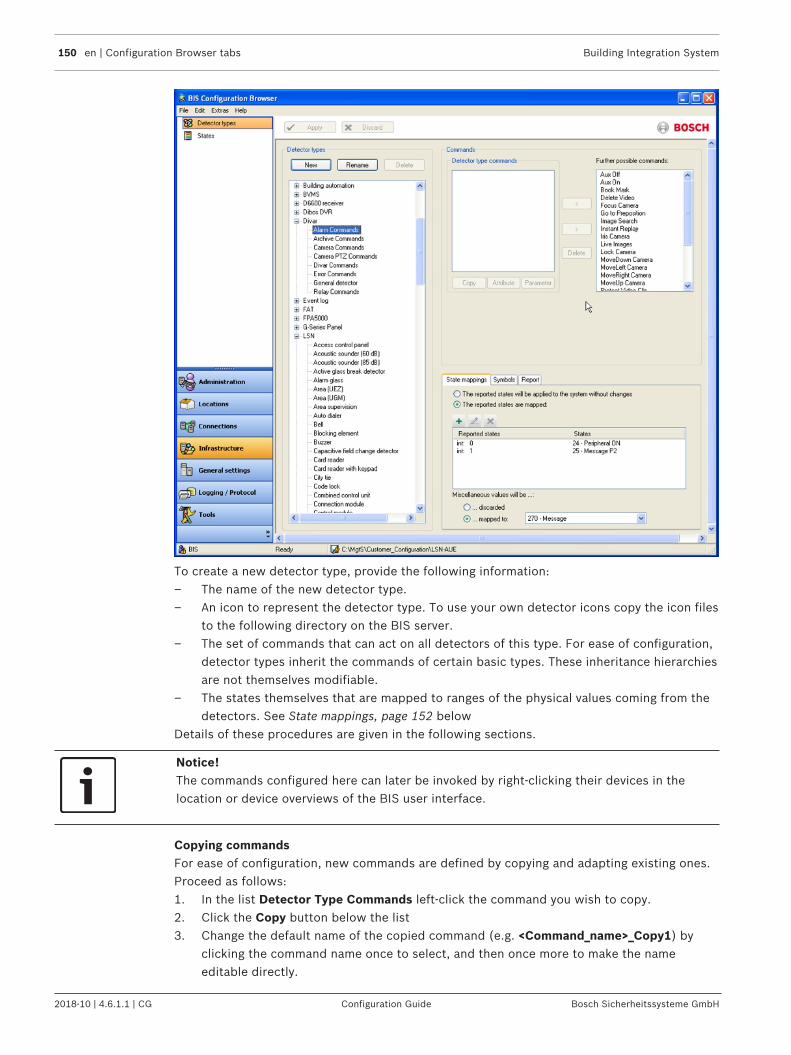
150 en | Configuration Browser tabs Building Integration System
2018-10 | 4.6.1.1 | CG Configuration Guide Bosch Sicherheitssysteme GmbH
To create a new detector type, provide the following information:– The name of the new detector type.– An icon to represent the detector type. To use your own detector icons copy the icon files
to the following directory on the BIS server.– The set of commands that can act on all detectors of this type. For ease of configuration,
detector types inherit the commands of certain basic types. These inheritance hierarchiesare not themselves modifiable.
– The states themselves that are mapped to ranges of the physical values coming from thedetectors. See State mappings, page 152 below
Details of these procedures are given in the following sections.
Notice!The commands configured here can later be invoked by right-clicking their devices in thelocation or device overviews of the BIS user interface.
Copying commandsFor ease of configuration, new commands are defined by copying and adapting existing ones.Proceed as follows:1. In the list Detector Type Commands left-click the command you wish to copy.2. Click the Copy button below the list3. Change the default name of the copied command (e.g. <Command_name>_Copy1) by
clicking the command name once to select, and then once more to make the nameeditable directly.
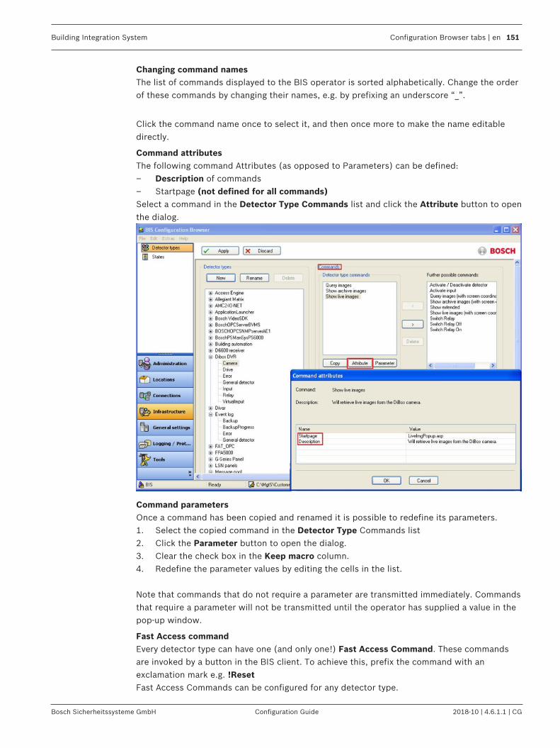
Building Integration System Configuration Browser tabs | en 151
Bosch Sicherheitssysteme GmbH Configuration Guide 2018-10 | 4.6.1.1 | CG
Changing command namesThe list of commands displayed to the BIS operator is sorted alphabetically. Change the orderof these commands by changing their names, e.g. by prefixing an underscore “_”.
Click the command name once to select it, and then once more to make the name editabledirectly.
Command attributesThe following command Attributes (as opposed to Parameters) can be defined:– Description of commands– Startpage (not defined for all commands)Select a command in the Detector Type Commands list and click the Attribute button to openthe dialog.
Command parametersOnce a command has been copied and renamed it is possible to redefine its parameters.1. Select the copied command in the Detector Type Commands list2. Click the Parameter button to open the dialog.3. Clear the check box in the Keep macro column.4. Redefine the parameter values by editing the cells in the list.
Note that commands that do not require a parameter are transmitted immediately. Commandsthat require a parameter will not be transmitted until the operator has supplied a value in thepop-up window.
Fast Access commandEvery detector type can have one (and only one!) Fast Access Command. These commandsare invoked by a button in the BIS client. To achieve this, prefix the command with anexclamation mark e.g. !ResetFast Access Commands can be configured for any detector type.

152 en | Configuration Browser tabs Building Integration System
2018-10 | 4.6.1.1 | CG Configuration Guide Bosch Sicherheitssysteme GmbH
Hiding commandsYou may also hide detector commands from operators. Hiding commands means preventingthem from appearing in the context menu of the detector type in the BIS client. To achievethis, prefix the command with a tilde character e.g. ~Reset
State mappingsIf the system records States (e.g. analog values from a thermometer) which do not match theregular States for an alarm system, then these values are usually mapped to States in order forBIS to interpret them. This process is known as State mapping.States can be mapped either to discrete values (e.g. “Switch open”, “Alarm” etc.) oralternatively to ranges of values (e.g. the mapping of temperature range “5° to 45°C” to State“Standby” and “46° to 70°C” to State “Pre-alarm”.The mapping applies to all detectors of the same type.
Displaying raw OPC dataSince BIS 3.0 it is possible to display analog values directly to the BIS user interface withoutstate mapping. A demonstration OPC server and a sample index page are provided with theBIS installation. For details see Displaying raw OPC data, page 88
To define a state mapping:1. Select Outlook button Infrastructure > Detector types2. Select a Detector type from the Detector types pane3. On the State mappings tab select the reported states are mapped option, then click the
New or Modify button.4. From the dialog that opens, select the Data type of the value as supplied by the
corresponding OPC server.5. Enter a Single value or Value range to be mapped and select a State for it, then confirm
with the OK button.
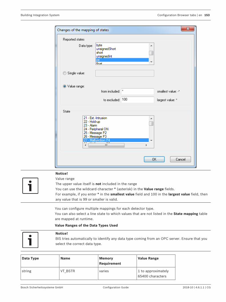
Building Integration System Configuration Browser tabs | en 153
Bosch Sicherheitssysteme GmbH Configuration Guide 2018-10 | 4.6.1.1 | CG
Notice!Value rangeThe upper value itself is not included in the rangeYou can use the wildcard character * (asterisk) in the Value range fields. For example, if you enter * in the smallest value field and 100 in the largest value field, thenany value that is 99 or smaller is valid.
You can configure multiple mappings for each detector type.You can also select a line state to which values that are not listed in the State mapping tableare mapped at runtime.
Value Ranges of the Data Types Used
Notice!BIS tries automatically to identify any data type coming from an OPC server. Ensure that youselect the correct data type.
Data Type Name MemoryRequirement
Value Range
string VT_BSTR varies 1 to approximately65400 characters

154 en | Configuration Browser tabs Building Integration System
2018-10 | 4.6.1.1 | CG Configuration Guide Bosch Sicherheitssysteme GmbH
boolean VT_BOOL 2 bytes True = -1, False = 0
unsignedByte VT_I1 1 byte -128 to 127
byte VT_UI1 1 byte 0 to 255
unsignedShort VT_UI2 2 bytes 0 to 65535
short VT_I2 2 bytes -32768 to 32767
unsignedInt VT_UINT 4 bytes 0 to 4294967295
int VT_INT 4 bytes -2147483684 to2147483647
float VT_R4 4 bytes for negative values:-3.402823E38 to-1.401298E-45 forpositive values:1.401298E-45 to3.402823E38
double VT_R8 8 bytes for negative values:-1.79769313486232E308 to-4.94065645841247E-324 for positivevalues:4.94065645841247E-324 to1.79769313486232E308
dateTime VT_DATE 8 bytes 01 January 100 to 31December 9999
DECIMAL VT_DECIMAL 16 bytes 16 byte fixed point
CY VT_CY 8 bytes -922337203685477.5808 to922337203685477.5807 (for currencies)
Click the Apply button to save any changes. After reloading the configuration the newcommand will appear in the context menus of detectors with the modified type State Mapping

Building Integration System Configuration Browser tabs | en 155
Bosch Sicherheitssysteme GmbH Configuration Guide 2018-10 | 4.6.1.1 | CG
State dependent detector symbols
You can so configure the detector type, that not only background color but also the symbolitself changes in accordance with the state.
To do this, proceed as follows:– Add the states needed to new or existing State Lists. Each state represented by another
symbol must be in a separate State List.– If you wish to use your own symbols, copy these icon files to the corresponding directory
on the BIS server. The default location is c:\MgtS\Default_Configurations\Common\Documents\Symbols
– Add an entry for each of those State Lists and select a graphic file for it
Examples:
Detector Types for Interface FaultsAn OPC server which also reports interface faults requires the detector type Error.The condition mapping must be so defined that the detector type Error reports to the OPCserver the state which was defined in the States list in the pane Malfunction States.New Detector Type “VIE Camera”The new (since BIS 2.3) virtual detector type “VIE Camera” offers the following commands:– Show live image– Show archive images– Search
If this virtual detector is configured you can view for example live pictures of this camera on aBIS client without (client-) VIE.

156 en | Configuration Browser tabs Building Integration System
2018-10 | 4.6.1.1 | CG Configuration Guide Bosch Sicherheitssysteme GmbH
Associating detector types with URLsSince BIS Version 2.3 a new command Show extended is potentially available to all detectortypes in BIS configurations, although not necessarily associated by default. The commandopens a new browser window at the URL which you enter as its first parameter, or elseprompts for the URL when the command is invoked by right-clicking the detector in theDevice- or Location overviews.
ProcedureIf your users need to be able to access a URL from a particular detector type you can add thecommand to its context menu as follows:1. In the Configuration Browser click Infrastructure > Detector types.2. Select the desired detector type from the Detector types list.3. Select the Show extended command from the list of Further possible commands and
place it in the list Detector type commands by clicking the < button.4. Select the Show extended command (now in the Detector typecommands list) and click
the Copy button to create a copy.5. Type over the name of the copy to rename it, if required. The name you choose will
appear in the detectors' context menus. (Note: Any number of copies can be made underdifferent names. When you have finished making copies you can return the original Showextended item to the list of Further possible commands by selecting it and clicking the >button.)
6. Select your copy and click the Parameter button. The Parameter entry dialog appears.7. Here you can enter the desired URL, the coordinates of the browser's top-left corner and
its window size. Note: it may be necessary to clear the Keep macro check box before youcan enter the URL.

Building Integration System Configuration Browser tabs | en 157
Bosch Sicherheitssysteme GmbH Configuration Guide 2018-10 | 4.6.1.1 | CG
8. Click the Apply button to save these changes. After reloading the configuration the newcommand will appear in the context menu of detectors of the modified type.
Notice!The first time an operator uses a Show extended command after logging on to the client, theymay experience a delay in opening the URL. The delay is commonly caused by the InternetExplorer checking by default for the revocation of certificates.Workaround: In Internet Explorer Options > Advanced tab clear the check boxes for followingitems:Check for publisher’s certificate revocationCheck for server certificate revocation
Associating BIS reports with detector typesSince BIS Version 2.3 a new command Show report can be invoked via the context menus ofall detector types in the BIS client. Its effect is to display the BIS report associated with thisdetector type.To associate a specific report with a detector type proceed as follows:1. Click the Reports tab in the lower right panel of the Detector types dialog2. Browse the desired report type using the “...” button (see the BIS Operation online help
for a description of the report types available). Both standard or user-defined reports canbe used.
13.13 Symbols and symbol-blinkingComposition of detector symbols (default)Detector symbols consist of vector graphics in .EMF format (EMF - Enhanced Metafile is a fileformat for vector graphics developed specially for 32-Bit Windows-Systems).
The factory default composition of these vector graphics (2D) is:– The square symbol frame - gray: (RGB: 127, 127, 127)

158 en | Configuration Browser tabs Building Integration System
2018-10 | 4.6.1.1 | CG Configuration Guide Bosch Sicherheitssysteme GmbH
– The symbol’s graphic (or alphanumeric) content - gray: (RGB: 127, 127, 127)*– The background color - green: (RGB: 0, 255, 0)**
*) The graphic symbolizes, for example, the respective detector type, its state or the object.**) Only this color setting allows the configuration of a color change, e.g. from green to red inthe case of an alarm.
Symbolic libraryAll detector symbols (<DetectorName>.emf) can be found in the symbol library on the BISserver under:c:\MgtS\Default_Configurations\Common\Documents\Symbols\2D or (...\3D)Around 150 prepared detector symbols (in two dimensional form) can be found in the 2Dsubfolder.
Blink modes for Detector symbolsThe following settings are available (singly or in combination):– Default Setting (Mode 1): The detector symbol’s background color (state dependent)
blinks.– Special setting (Mode 2): The detector symbol’s graphic and frame blink on a green
background– Special setting (Mode 3): The whole detector symbol blinks (frame, graphic and
background color)Differentiating between patterns
Modes What is blinking? Filename Background color
Mode 1 (Default) only background <Detector Name>.emf Green (RGB: 0,255,0)
Mode 2 Frame and symbolgraphic
<Detector Name>.emf Green (RGB: 0,255,0)
Mode 3 Whole detectorsymbol (Frame,Symbol graphic andbackground)
<Detector name>.cmf Alternating green, e.g. blue***
***) Blue (RGB: 0, 0, 255) or an RGB color mix (however no color alternation can beconfigured for colors other than green.)
Changes in blink modesIn order to change a symbol's default blink mode (i.e. mode 1) to mode 2 or 3, make followingchanges:– To set blink mode 2 Change the file extension of the relevant symbol’s file to .CMF (Corel
Metafile), e.g. <DetectorName>.emf to <DetectorName>.cmf– To set blink mode 3:
– Change the file extension of the relevant symbol’s file to .CMF (Corel Metafile).– Additionally, change the background color of this file (e.g. from green to blue)
Notice!Color changes to detector symbols can only be carried out using vector graphic editors, suchas Adobe Illustrator, not with raster graphic editors.

Building Integration System Configuration Browser tabs | en 159
Bosch Sicherheitssysteme GmbH Configuration Guide 2018-10 | 4.6.1.1 | CG
Notice!If all blink modes are to remain available for this detector symbol, then any changes to Mode2 and Mode 3 should be carried out on copies of the original files, taken from the symbollibrary.
Notice!In order to use them, any new or modified symbols must be made available again in thesymbol library folder:C:\MgtS\Default_Configurations\Common\Documents\Symbols\2D
13.14 Application LauncherThe application launcher provides a means of starting arbitrary housekeeping processes orapplications from within BIS. The processes are always run:– on the BIS Server– as background processes (they do not appear in the Windows foreground)– under the user MgtS-Service
Typical examples of applications you may wish to start in this way are data imports/exports,backups or deletions of accumulated report files.
Note: BIS already provides a means of starting arbitrary applications on-the-fly:Device Overview > Devices > Application Launcher > Start > (right click for context menu ) >Start ApplicationHowever, the advantage of pre-defining applications in the Configuration Browser is that theyappear under user-defined names with pre-defined parameters and timeouts. Hence the end-user does not have to enter all these details on-the-fly.
Defining launchable applications in the Configuration Browser1. Select the Infrastructure Outlook button, then click Detector type.
2. Click the Copy button to copy one of the template applications Start application or Startconfiguration backup. Give the application a new name (this example: My New App).
3. Then click the parameter button to define the following:– the command line to be invoked– a period of time in seconds (here 1hr = 3600 seconds) during which the started
application will be monitored. If the application does not terminate normally withinthis period, an error message is generated.
– a flag to determine whether the application should be terminated when the periodhas expired.

160 en | Configuration Browser tabs Building Integration System
2018-10 | 4.6.1.1 | CG Configuration Guide Bosch Sicherheitssysteme GmbH
Notice!If the boxes in column Keep Macro are left checked, then the application will automaticallyprompt for these parameters at run time.
1. The configuration must then be saved and reloaded in BIS, in order to become effective.2. Thereafter the new application is available in BIS under: Device Overview > Devices >
Application Launcher > Start > (right click for context menu)
13.15 Virtual deviceUse virtual devices to group detector points that have the same functions (for example, powerfailure detectors installed throughout a building).
Use the Virtual device Configuration Browser item to define the server-specific data for allconnection types set up on the Connections Configuration Browser window.Click here for more information on: Connections and Addresses, page 135For each virtual device used, you can:– Set the interface parameters– Assign or browse to addresses
Configuring Virtual DevicesFrom the Configuration Browser, select the General Settings Outlook button, then clickVirtual device.

Building Integration System Configuration Browser tabs | en 161
Bosch Sicherheitssysteme GmbH Configuration Guide 2018-10 | 4.6.1.1 | CG
This screen allows you to define virtual devices for procedures or line conditions which existonly as logical functions, but not as actual devices. They appear under the virtual componentas elements in the device tree, and can be a part of different links.
Select the Configuration Browser's Locations tab, then click Detector placement. Anchor thevirtual data like a normal detector (for example, using hyperlinks in a floor plan).Click here for more information on: Detector placement, page 141

162 en | Configuration Browser tabs Building Integration System
2018-10 | 4.6.1.1 | CG Configuration Guide Bosch Sicherheitssysteme GmbH
Select the Configuration Browser's General Settings tab, then click Associations. Withassociations, too, you can use virtual devices like genuine devices (for example, you cangenerate a message or configure a control process for a virtual device).Click here for more information on: Associations (Jobs) - an overview, page 173
13.15.1 Example: Configuration of a Virtual DeviceConfigure a virtual detector that reports when all window contacts on the 1st floor are closed.
Preliminary steps for setting up the virtual detector

Building Integration System Configuration Browser tabs | en 163
Bosch Sicherheitssysteme GmbH Configuration Guide 2018-10 | 4.6.1.1 | CG
1. Select the Infrastructure tab in the Configuration Browser, then click States.
2. Define the required state list (for example, line condition 101 “1st floor mag contactsclosed”), then click Apply.
3. Select the Configuration Browser's Locations tab, then click Tree structure. Create thelocation “1st floor” and link it to the corresponding floor plan. (Optional: The hyperlink tothe virtual detector “All magnetic contacts” is inserted in the floor plan.)

164 en | Configuration Browser tabs Building Integration System
2018-10 | 4.6.1.1 | CG Configuration Guide Bosch Sicherheitssysteme GmbH
4. Select the Configuration Browser's Infrastructure tab, then click Detector type. Createand define the virtual magnetic contacts. As an option you could, for example, use thenormal magnetic contact symbol for the virtual detector “All magnetic contacts”, butemphasize it by making it extra-large when defining the hyperlink.
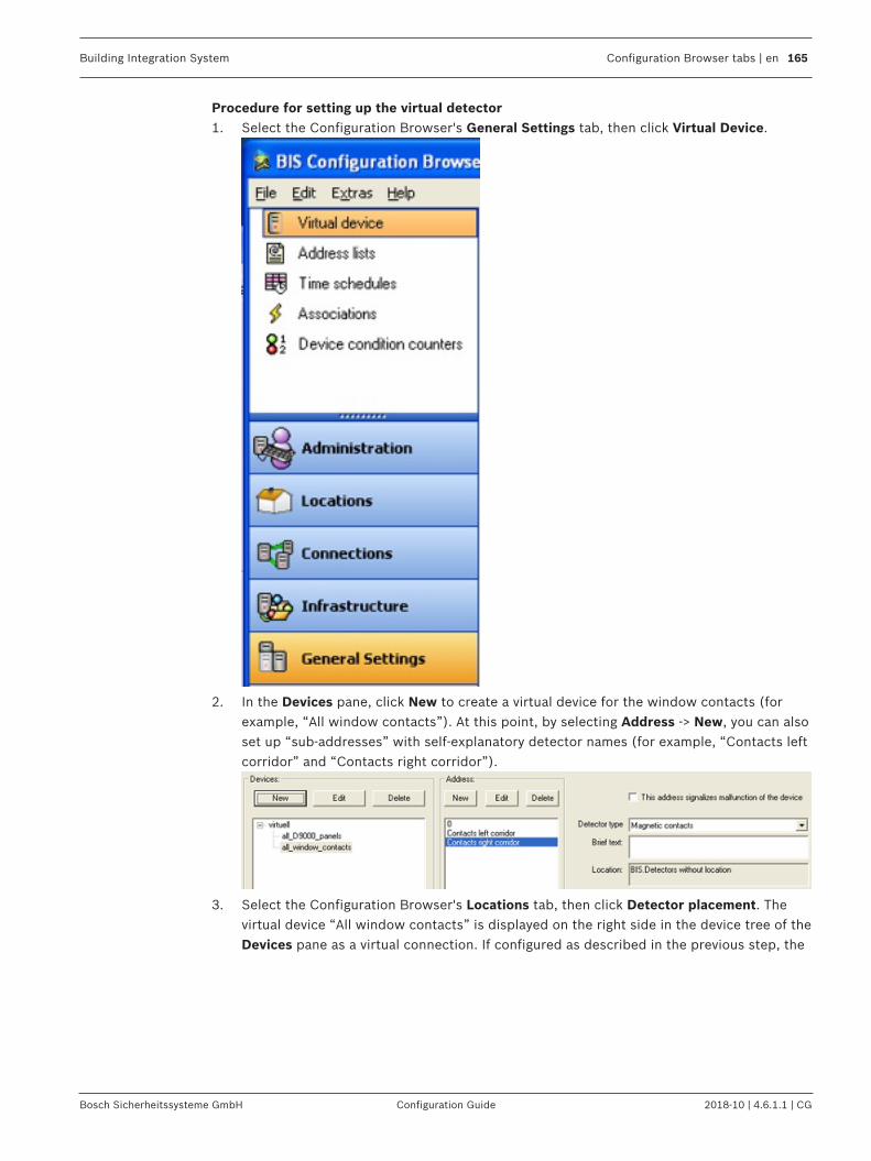
Building Integration System Configuration Browser tabs | en 165
Bosch Sicherheitssysteme GmbH Configuration Guide 2018-10 | 4.6.1.1 | CG
Procedure for setting up the virtual detector1. Select the Configuration Browser's General Settings tab, then click Virtual Device.
2. In the Devices pane, click New to create a virtual device for the window contacts (forexample, “All window contacts”). At this point, by selecting Address -> New, you can alsoset up “sub-addresses” with self-explanatory detector names (for example, “Contacts leftcorridor” and “Contacts right corridor”).
3. Select the Configuration Browser's Locations tab, then click Detector placement. Thevirtual device “All window contacts” is displayed on the right side in the device tree of theDevices pane as a virtual connection. If configured as described in the previous step, the

166 en | Configuration Browser tabs Building Integration System
2018-10 | 4.6.1.1 | CG Configuration Guide Bosch Sicherheitssysteme GmbH
groups “Contacts left corridor” and “Contacts right corridor”, which can also be anchoredwith hyperlinks, appear.
4. Choose the appropriate location from the location tree on the left hand side. The existinglinks of the location plan are listed automatically.
5. In the Mapped detectors of location pane, select the Detector directly at location tab.In the device tree below, select the virtual device All window contacts. Pressing the leftmouse key, drag the whole device (or individual groups/detectors/sensors displayedalongside on the right) into the Mapped detectors of location field.
Using the virtual detector in an AssociationIn order to make effective use of the virtual detector for message-generation and system-control purposes, it can be embedded in an Association. Proceed as follows.1. Select the Configuration Browser's General Settings tab, then click Associations.2. Create a trigger and enter the virtual detector’s address in the Address field.

Building Integration System Configuration Browser tabs | en 167
Bosch Sicherheitssysteme GmbH Configuration Guide 2018-10 | 4.6.1.1 | CG
13.16 Address listsAddress lists are used for bundling addresses so that they can be manipulated as groupsrather than individuals. This extra level of abstraction greatly enhances the power andeffectiveness of the Building Integration System.
Examples of uses for Address lists– To enable Control Commands to manipulate all the detectors in one part of a building,
for example, all detectors on the third floor.– To enable Associations to trigger on any events of a particular type.– To enable the use of Device Condition Counters.– To assign Authorizations over many devices at once.– To unlock all ground floor doors at once, in the event of an emergency.– To trigger print jobs or event log tasksTo define and modify Address lists, navigate to the dialog as follows:In the Configuration Browser select General settings > Address lists.
Orientation in the Address lists dialogThe main dialog for Address lists is divided into 3 panes:

168 en | Configuration Browser tabs Building Integration System
2018-10 | 4.6.1.1 | CG Configuration Guide Bosch Sicherheitssysteme GmbH
– Address lists: (left side) contains the names of Address lists that already exist in theconfiguration.
– Detector addresses: (upper right) displays the addresses that have been defined for theAddress list that is currently selected in the Address lists pane.
– Addresses of the selected item (lower right) displays details about the addresses thatare currently selected in the Detector addresses pane. If an address range is selected in the Detector addresses pane then the individualaddresses of that range are listed here.
Creating address lists1. Click the New button at the top of the Address lists pane, and overwrite the default
name Unnamed <integer> with an appropriate name.– Click on the name to select it for filling.– Alternatively left-click one of the existing default address lists to select it for filling.
2. Click the New button at the top of the Detector addresses pane to invoke the Addressselection dialog box.
3. When you have finished creating and filling address lists, click the Apply button to savethem to your configuration.
Editing Address listsThe Address selection dialog box is a powerful tool for accumulating individual addresses andaddress ranges into an address list.Selection of list items in general:Left-click with the Shift key to select address ranges, that is multiple contiguous addresses. Left-click with the Ctrl key to select multiple noncontiguous addresses.
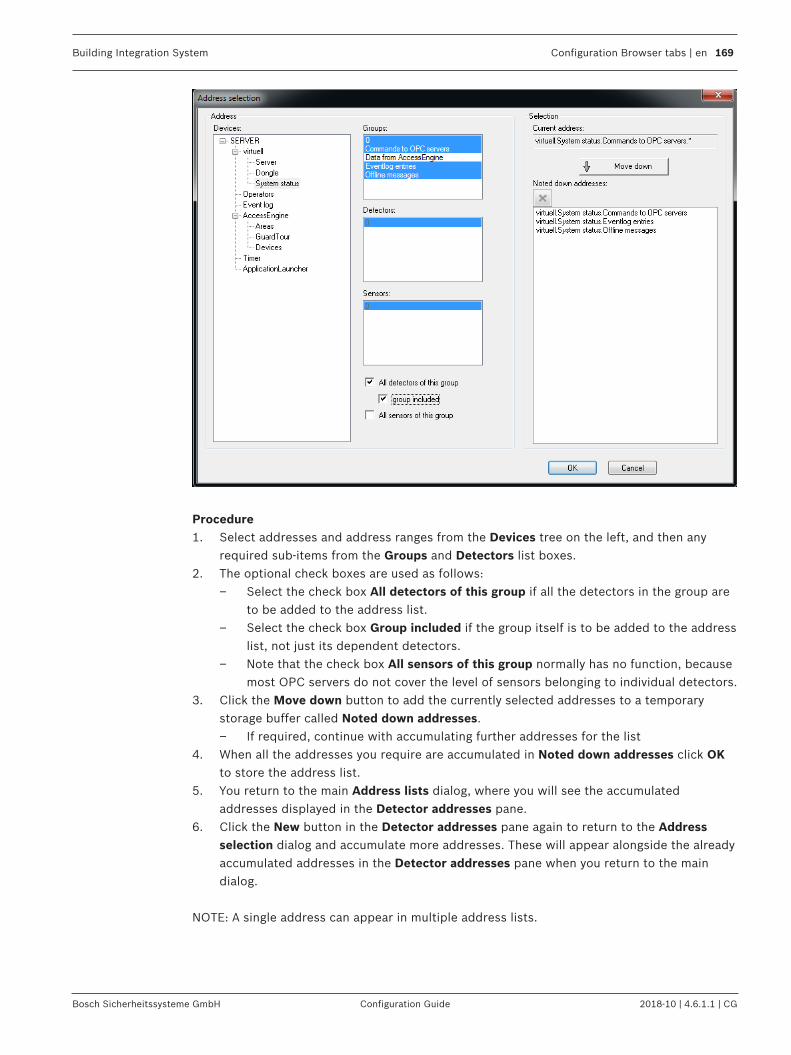
Building Integration System Configuration Browser tabs | en 169
Bosch Sicherheitssysteme GmbH Configuration Guide 2018-10 | 4.6.1.1 | CG
Procedure1. Select addresses and address ranges from the Devices tree on the left, and then any
required sub-items from the Groups and Detectors list boxes.2. The optional check boxes are used as follows:
– Select the check box All detectors of this group if all the detectors in the group areto be added to the address list.
– Select the check box Group included if the group itself is to be added to the addresslist, not just its dependent detectors.
– Note that the check box All sensors of this group normally has no function, becausemost OPC servers do not cover the level of sensors belonging to individual detectors.
3. Click the Move down button to add the currently selected addresses to a temporarystorage buffer called Noted down addresses.– If required, continue with accumulating further addresses for the list
4. When all the addresses you require are accumulated in Noted down addresses click OKto store the address list.
5. You return to the main Address lists dialog, where you will see the accumulatedaddresses displayed in the Detector addresses pane.
6. Click the New button in the Detector addresses pane again to return to the Addressselection dialog and accumulate more addresses. These will appear alongside the alreadyaccumulated addresses in the Detector addresses pane when you return to the maindialog.
NOTE: A single address can appear in multiple address lists.
170 en | Configuration Browser tabs Building Integration System
2018-10 | 4.6.1.1 | CG Configuration Guide Bosch Sicherheitssysteme GmbH
Caveats for Address lists
Notice!Use only alphanumeric characters in the names of address lists.
Notice!Address lists are limited to 10,000 addresses each.
Notice!An Address list can contain addresses and/or address ranges from several subsystems. Forexample, the detector groups 100 to 110 of subsystem UEZ1 and the addresses 60, 64, 67,and 69 of subsystem UEZ2.
See also– General procedure for configuring Associations, page 178– Device state/condition counters, page 192– Authorizations, page 118
13.17 TimerSelect the Configuration Browser's General Settings Outlook button, then click Timer.

Building Integration System Configuration Browser tabs | en 171
Bosch Sicherheitssysteme GmbH Configuration Guide 2018-10 | 4.6.1.1 | CG
With Timers/time schedules you can define any program schedules you require. You can defineup to four time slices (four periods) for each of the following:– All days of the week– Up to 30 Extra days (freely definable special days in your calendar)
All the time slices (time periods) of a scheduled program are considered together todetermine whether or not a scheduled program should be active at a particular time on aparticular day. Scheduled programs are often used in Associations.Use the corresponding buttons to create, rename, or delete a scheduled program.
Notice!The following characters are not allowed in Time Schedules: # < > ' " & * ? .
Notice!Extra days have higher priority than weekdays. Therefore, if an Extra day falls on a Thursday,and if a scheduled program is configured for the Extra day, it overrides the scheduledprogram that would normally be active on the Thursday.
Procedure for Configuring Time Schedules1. Click the New button to create a scheduled program (for example, “Banking hours”).2. Select the Week tab and then highlight a day (for example, “Monday” to “Sunday”)3. Enter times in the fields for time slices (“Time1” through Time4”), and then click the
desired day of the week to transfer the time slice to that day.
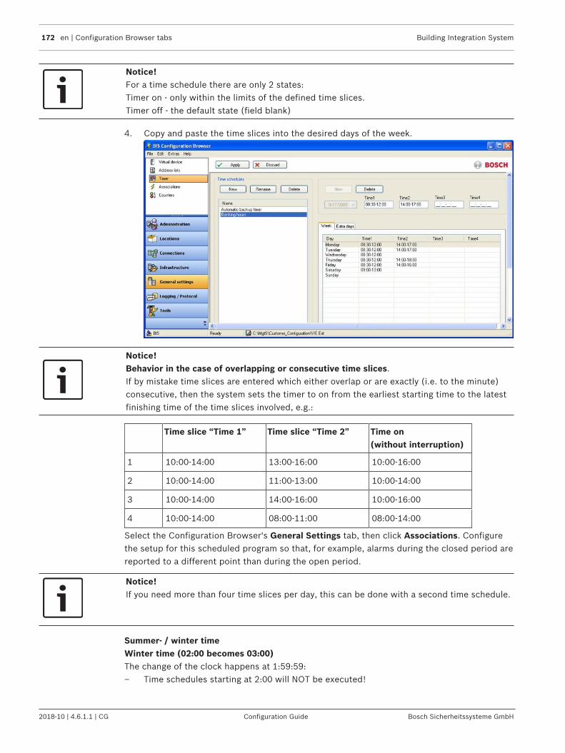
172 en | Configuration Browser tabs Building Integration System
2018-10 | 4.6.1.1 | CG Configuration Guide Bosch Sicherheitssysteme GmbH
Notice!For a time schedule there are only 2 states:Timer on - only within the limits of the defined time slices.Timer off - the default state (field blank)
4. Copy and paste the time slices into the desired days of the week.
Notice!Behavior in the case of overlapping or consecutive time slices.If by mistake time slices are entered which either overlap or are exactly (i.e. to the minute)consecutive, then the system sets the timer to on from the earliest starting time to the latestfinishing time of the time slices involved, e.g.:
Time slice “Time 1” Time slice “Time 2” Time on(without interruption)
1 10:00-14:00 13:00-16:00 10:00-16:00
2 10:00-14:00 11:00-13:00 10:00-14:00
3 10:00-14:00 14:00-16:00 10:00-16:00
4 10:00-14:00 08:00-11:00 08:00-14:00
Select the Configuration Browser's General Settings tab, then click Associations. Configurethe setup for this scheduled program so that, for example, alarms during the closed period arereported to a different point than during the open period.
Notice!If you need more than four time slices per day, this can be done with a second time schedule.
Summer- / winter timeWinter time (02:00 becomes 03:00)The change of the clock happens at 1:59:59:– Time schedules starting at 2:00 will NOT be executed!

Building Integration System Configuration Browser tabs | en 173
Bosch Sicherheitssysteme GmbH Configuration Guide 2018-10 | 4.6.1.1 | CG
– Time schedules starting at 1:55 and ending at 2:30 will run effectively from 1:55 - 3:00(approx. 5 min.)
Summer time (3:00 -> 2:00)The clock shows 2:00:00 in the second after 2:59:59:– A time schedule 2:15 -> 3:15 runs 1h longer. In the change 3->2 the time schedule does
not end!– A time schedule 2:05 -> 2:15 runs only once - after the change 3->2 the time schedules is
not started for a second time.
13.18 Associations (Jobs) - an overviewAssociations (also known as Jobs) are the IF-THEN rules which govern the behavior of the BISsystem. When the BIS server is running its State Machine constantly monitors the states ofconnected devices, timers and messages, and matches them against all the Associations thatare stored in the currently loaded configuration. Whenever one of the TRIGGERs of anAssociation is fulfilled, then the State Machine executes that Association. First it checks thatall additional prerequisites (i.e. the IF clauses) are fulfilled, and if so, carries out thecommands in the THEN clauses. Otherwise it carries out the actions in any ELSE clauses thatthe Association may have.
The key elements in an Association are therefore:– Triggers (preconditions linked by a logical OR)– IF clauses (additional conditions, linked by a logical AND). Note: IF clauses are optional,
because Triggers by themselves can play the role of preconditions for the Association.– THEN clauses– ELSE clauses
The effects of an Associations (i.e. the THEN and ELSE clauses) can be to change line states,create messages, set timers, set variables or send commands to devices. These are describedin more detail below.
To create an Association, select the Configuration Browser's General Settings tab, then clickAssociations.

174 en | Configuration Browser tabs Building Integration System
2018-10 | 4.6.1.1 | CG Configuration Guide Bosch Sicherheitssysteme GmbH

Building Integration System Configuration Browser tabs | en 175
Bosch Sicherheitssysteme GmbH Configuration Guide 2018-10 | 4.6.1.1 | CG
13.18.1 Elements of Associations1. Job:Job is the generic term for a particular task (Job is basically a synonym for the Associationitself). The job may contain one or more “triggers” which serve in a logical OR as theprerequisites for performing that job/task.For example, the job “monitor parking lot” could contain the triggers “car entering”, “carleaving” and “gate closure”. In this example any of the triggers can fulfill the prerequisites toperform the job “monitor parking lot”.
2. Trigger:A trigger is an initial precondition for a job. It can be fulfilled by a state change in an address,address list, message or timer.
Parameters of triggers: Possible state transitions:
Explicit addresses of connections Any state to any other state
Address elements of Address Lists Any state to any other state
Timers (measuring, for example, the timetaken by individual steps in messageprocessing)
Running to StoppedRunning to Time Out
Message states Possible states:– Not yet delivered (for example, a
message is created but nobody is loggedon)
– Delivered (but not yet accepted)– Accepted (but not deleted)– Workflow messages (not yet sent)– DeletedSee the table below for possible statetransitions.
Some notes on Timers:– Timers are created by clicking the New button in the Timer pane. The default name is
“Unnamed”, followed by “Unnamed 1”, “Unnamed 2” etc. to a maximum of“Unnamed 999”. Bosch recommends that the defaults be replaced by more meaningfulnames, to avoid reaching the numbering limit.
– The maximum timer value is 2147482 sec, which is almost 25 days.– Timers are not assigned any time value (for example, “10 seconds”). You must configure a
start and/or end value.– Variables and timers are local to their jobs. They do not affect other jobs, and Job X can
not make use of variables defined for job Y.
The following table shows which message state transitions are possible (yes) or impossible(no).
StateChange
TO: New (NotDeliveredYet)
Delivered(New orWorkflow)
Accepted(Acknowledged)
Workflow(Not SentYet)
Deleted Timeout

176 en | Configuration Browser tabs Building Integration System
2018-10 | 4.6.1.1 | CG Configuration Guide Bosch Sicherheitssysteme GmbH
FROM:
New (NotDeliveredYet)
no yes no no no yes
Delivered(New orWorkflow)
no no yes no yes yes
Accepted(Acknowledged)
no no no yes yes yes
Workflow(Not SentYet)
no yes no no no yes
3. IF clauseTriggers can be made more precise by adding IF clauses to them. IF clauses are optional,because the triggers themselves can serve as preconditions.– IF (additional condition): If multiple IFs are used, then they are linked by a logical AND.
A trigger can have multiple AND-linked conditions. For OR-links, use multiple triggers. Thetrigger is only fulfilled if all its IF conditions are met. The following table summarizes thescope of IF clauses.
Parameters of IFclauses
Possible status values Possible comparisonoperators
Explicit address ofconnections
All line states =, !=, >, >=, <, <=(equals, does not equal, greaterthan, greater than or equal to,less than, less than or equal to)
Variable Any positive decimal values =, !=, <, <=, >, >=
Attributes (that is, valuesadditionally supplied bythe OPC server, such asADI in the case of LSN)
-Delete-Report-Do not delete-Do not reportNOTE: You can also createcustom attributes.
=, !=
Example: ADI (ADI Advanced-Display-Information (DPI Display-Print-Information) in the case ofLSN)

Building Integration System Configuration Browser tabs | en 177
Bosch Sicherheitssysteme GmbH Configuration Guide 2018-10 | 4.6.1.1 | CG
4. THEN clause– THEN (= control/action): If multiple THENs are used, then they are executed in the order
listed. The performance of these control operations is logged.You can assign the following in a THEN clause:
Parameters that can be theobject of a THEN controloperation
Possible control operations(examples)
Possible parameters for theevaluation
Explicit addresses ofsubsystems
Building control, Settemperature
=, !=, <, <=, >, >= (forexample, >= 80)
Video matrix Zoom In/ZoomOut
Number of steps
LSN Reset A state (aka line condition)
Block LSN ON/OFF
LSN sensor functionalitycheck
ON/OFF
All elements of an AddressList
See above See above
Message Generate Alarm address
Alarm status
Time Out per user status
Timer START Time Out
STOP ------
Variable SET (set to) Decimal value

178 en | Configuration Browser tabs Building Integration System
2018-10 | 4.6.1.1 | CG Configuration Guide Bosch Sicherheitssysteme GmbH
ADD (Add) Decimal value
SUB (subtract) Decimal value
MULT (multiply) Decimal value
DIV (divide) Decimal value
5. ELSE clause– ELSE (= alternative control/action): These are executed in the order listed whenever the
trigger is fulfilled but the IF conditions are not fulfilled.Their objects, control operations, and parameters, are the same as for THEN clauses.
Activation/deactivation of state machine associationsFor testing or maintenance purposes, it is possible to activate or deactivate elements in theAssociation tree by selecting the check box field in the tree. The check box fields in theAssociation tree have three states:
= The element and all child elements are active.
= The element and all child elements are NOT active.
= The element itself is active, but there are one or more deactivated child elements.
13.19 General procedure for configuring AssociationsFor each association/job, adhere to the following general procedure:1. Create the job and give it a meaningful name (for example, “Door control”).2. (Optional) In the Timer field, create any timers required and give them meaningful names.4 (Optional) In the Variable field create any variables and give them meaningful names.
1. (Required) Select the job, create a trigger, give it a meaningful name, enter theparameters, and enter useful comments in the comments field.
2. (Optional) Select the trigger, create one or more “IF”-clauses; give each a meaningfulname using the comment field, and enter the parameters.
3. (Optional) Select the trigger, create one or more control clauses (THEN and ELSE), giveeach a meaningful name using the comment field and enter the parameters.
Right-click nodes in the tree of links in order to do the following:– Copy and paste statements– Disable statements, including parts of statements for test purposes, which can then be
used again later
Recommendations– Use Address Lists and State Lists as much as possible. This can considerably reduce the
amount of copying and pasting required. See Address lists, page 167– Give descriptive names to the individual elements of an association, to make them easier
to debug.

Building Integration System Configuration Browser tabs | en 179
Bosch Sicherheitssysteme GmbH Configuration Guide 2018-10 | 4.6.1.1 | CG
Notice!The BIS state machine takes account of supervision addresses when processing Associations:If, for example, an address goes into a state X that triggers an Association, and if that addresssignals the same state X after having signaled a malfunction on the supervision address in themeantime, then the BIS state machine recognizes that state X was the last valid state beforethe malfunction, and does not trigger the Association again for the same address.For more details on defining Associations see General procedure for configuring Associations,page 178
13.20 Message timeouts, distribution and escalationMessages can be created in THEN or ELSE clauses of Associations.
TimeoutsMessage timeouts can be used to react automatically if a message is not delivered, or notprocessed by an operator, within a specified time.Timeouts provide a means of triggering a follow-up alarm, for instance at a higher priority orwith additional acoustic signals, if there has been insufficient reaction to the original alarm.
Defining a timeout– In the Timeouts panel, select one or more of the message conditions on which to react,
and enter a timeout period in seconds.

180 en | Configuration Browser tabs Building Integration System
2018-10 | 4.6.1.1 | CG Configuration Guide Bosch Sicherheitssysteme GmbH
– Not delivered: no-one who could process the message is logged on– Delivered: the message is in the queue in condition New– Accepted: the message has been accepted but not deleted– Workflow not yet delivered: the message is in condition Workflow, but no-one with
the required authorization is logged on.– Timeouts start counting seconds as soon as the state change that caused the message is
detected by the BIS State Machine.– After the time has elapsed the condition of the current message is set to TimeOutNote: These timeouts are unrelated to timeouts in the escalation process, compare Messageescalation, page 180
Using a timeout– For example, create a new trigger of type Message that reacts when the condition of a
message is set to TimeOut.
Message distributionBy default messages are sent to all Authorizations immediately. You can change this byselecting of the radio button only following permissions in the distribution panel.– As soon as they are generated messages are sent immediately to all authorizations whose
check boxes are selected in the left panel.– If no authorization is selected, the message is escalated after a few seconds to a potential
receiver in the right hand panel. Note: In this case the timeout period in the right panel isignored.
– If one or more authorizations are selected, or if the radio button all permissions isselected, but no one accepts the message, then the message may be escalated asfollows:
Message escalation– The right hand panel defines the times and order of further message escalations and is to
read from top to bottom:– The message will be sent after [Timeout] seconds to the [Authorization] specified
13.21 Examples of AssociationsThis section contains examples of useful Associations.
13.21.1 Example of tracking totals using AssociationsIn an underground car parking garage with 100 parking spaces, a light barrier detects each caras it enters. When a car drives through the light barrier, the message “car entering” appears inthe porter's office. If there are 100 cars in the underground parking garage, the message“garage full” is output.
A. Preparing to configure Associations– The required states, such as 090 “car entering” and 091 “garage full” must be defined in
the States Configuration Browser item.– The location “underground garage” must be created in the Tree structure dialog and is
linked to the corresponding floor plan. The hyperlink to the detector “light barrier” isinserted in the floor plan.
– The light barrier is created and defined as a detector in the Detector Type dialog.

Building Integration System Configuration Browser tabs | en 181
Bosch Sicherheitssysteme GmbH Configuration Guide 2018-10 | 4.6.1.1 | CG
– In the Detector placement dialog, the light barrier is assigned as a detector in the floorplan.
B. Setting Up the Association1. From the Configuration Browser, select the General Settings tab, then click
Associations. Click Job:New to create a new job called “Underground garage”.2. Click New or the right mouse button to create a trigger. Specify under Type what the
trigger will respond to. In this case it is the light barrier, so select Address. Enter anexplanation in the Comments field, such as “light barrier”.
3. From ensuing the device tree select the appropriate detector (the light barrier's address).The Trigger of address type is then displayed on the Associations page.
4. Define the other parameters of the trigger. Select the check box All sensors of thisdevice, since there is only one detector, and enter the line condition change. In this case,the change from OLD = 005 STANDBY to NEW = 090 CAR ENTERING.
5. Every time the light barrier responds, a count (equal to a control operation) takes place,so a THEN clause must be inserted in the trigger, and a variable entered as the object ofthis control operation. This variable is usually set up before the trigger is configured. Gointo the Variable pane and click New to set up the variable for the car count. Enter aname, such as “Counter variable” and a starting value of “0”.
6. Insert the THEN clause by clicking the Control: New button, or right-click in the trigger.Select Variable as the object, and in the comments line enter an explanation describingthe THEN clause (for example, “car count”).
7. Define the THEN clause in the THEN of 'Variable' type field by selecting the variable“Counter variable” and giving the instruction ADD for the desired control operation (inthis case, add the variable value). In the Value field, state by how much to increment thecounter (in this case, a value of “1” for each incoming car).
8. The progress of the counter variables is checked using an IF element which you mustinsert in the trigger. Because you must always set up the trigger sequence according tothe IF -> THEN -> ELSE pattern, and the trigger “light barrier” already starts with a THENclause, you must create a new trigger for the IF element.
9. Click on the job (in this case, “Underground garage”), and then right-click to create a newtrigger with the already-known address of the light barrier. In the comments line, enter adescription for the trigger, such as “check variable”.
10. Add the IF element (by right-clicking or by using Condition -> New). Select the Variableoption of the object and, in the comments line, enter a description for the IF condition,such as “end value reached”.
11. Define the IF element in the IF of 'Variable' type field. Select the corresponding variable(in this case: “counter variable”), enter a comparison operator (in this case, “=“) and avalue (in this case, enter “100” as the end value representing the capacity of theunderground garage).
12. Click the element IF: End value reached and right-click to create a THEN clause ofMessage type, because a message should be generated when the condition “Variable =100" is met.
13. Define the THEN clause in the THEN of 'Message' type field by selecting the Use alarmaddress check box and, for Line status, not selecting the check box Use alarm status.Instead, from the list field on the right, select the status which you defined: 091 GARAGEFULL.
14. Click the THEN clause and right-click to insert an ELSE element of Message type, so that,as long as the variable check does not produce the end value = 100, the message “carentering” appears in the porter's office.

182 en | Configuration Browser tabs Building Integration System
2018-10 | 4.6.1.1 | CG Configuration Guide Bosch Sicherheitssysteme GmbH
15. Define the ELSE element in the ELSE of 'Message' type field by selecting the check boxUse alarm address and, for Line status, not selecting the check box Use alarm status.Instead, from the list field on the right, select the status which you defined: 090 CARENTERING.
C. Summary of StepsThe “Job: Underground garage” example consists of the following logical configuration steps:1. First trigger: Status transition (change) at the light barrier.2. THEN: Car count (with the help of a predefined variable).3. Second trigger: Check changes to variable.4. IF: End value reached.5. THEN: Message “Garage full”.6. ELSE: Message “Car entering”.
Click here for more information on: Message timeouts, distribution and escalation, page 179
13.21.2 Example of configuring a security system using Associations
Requirement:A Security System (SecSys) must already be configured.
First Association:For all status changes reported by the SecSys containing the display/print information"Report", a message should display at the BIS user interface.1. Create a new job with the name “SecSys-Messages”.2. Create a new trigger of Address type called “SecSys”.3. In the device tree, select the SecSys and then the option All detectors of this device and
All groups of this device.4. Create a new condition of object type Attribute called “ADI Report”.5. Select the attribute REPORT, the comparison operator = and the value Report.6. Create a new control operation of object type Message called “Message” and leave all
settings at their default values.
Second Association:When a SecSys message is acknowledged, a corresponding acknowledgement telegram isgenerated automatically and sent to the SecSys.1. Select the job “SecSys messages”.2. Create a new trigger of Message type called “Message acknowledged”.3. For the message status NEW select Acknowledged.4. De-select the check box Any Address and select the SecSys in the device tree.5. Select the option All detectors of this device and All groups of this device.6. Create a new control operation of object type Address called “Acknowledgement
telegram”.7. Select the command SecSys: Acknowledge. Do not make further entries.8. Click OK to confirm your selection.
Third Association:When a SecSys message is deleted, a corresponding deletion telegram is generatedautomatically and sent to the SecSys1. Select the job “SecSys messages”.2. Create a new trigger of Message type called “Message deleted”.3. For the message status NEW select = “deleted”.4. De-select the check box Any Address and instead select the SecSys in the device tree.
Building Integration System Configuration Browser tabs | en 183
Bosch Sicherheitssysteme GmbH Configuration Guide 2018-10 | 4.6.1.1 | CG
5. Next, select the option All detectors of this device and All groups of this device.6. Create a new control operation of object type Address called “Deletion telegram”.7. Select the command SecSys: Delete. Do not make further entries.8. Click OK to confirm your selection.
Fourth Association:One-click user alarm with automatic acknowledgement.1. Insert a virtual detector in the configuration client (for example, “User alarm”).2. On the Detector placement page, assign the virtual detector created above (“User
alarm”) to a desired location (or place it in a graphic).3. Use FrontPage to insert an action button on the interface HTML page.4. On the properties page of the action button, state the name of the button (“User alarm”).5. Select the command “Virtual. Set status with event attribute” and add it to the button
command to be executed. Replace both parameters:Status: desired message statusEvent attribute: AutoAcknowledgeDo not change or replace any other parameters.
6. Enter the address of the virtual detector created above (for example, “virtual useralarm”).
7. Select the authorizations which may process this message.8. Do not set the properties “Mandatory” and “Parameters from message”.9. Close the properties dialog of the action button and save the HTML page.10. Using the Configuration Browser's General Settings tab, select Associations and create a
new job “User alarm”.11. Create a new trigger of Address type called “User Alarm Message”, and select the virtual
address entered above (“virtual user alarm”).12. For the line status NEW, select the status entered above as the action button status to
send.13. Create a new control operation of object type Message called “Message” and leave all
settings at their default values.14. Create a new trigger of Message type called “User alarm deleted”.15. For the message status NEW, select = “deleted”.16. De-select the check box Any address and instead select the virtual address in the device
tree (for example, “virtual user alarm”).17. Create a new control operation of object type Address called “Standby status”.18. Select the command virtual: set status with state “5” (= “standby”).
13.21.3 Example of automatic backup of the event log using AssociationsRequirement:The state machine must automatically trigger the backup of the event log.
Important decisions regarding automatic backup of the Event Log– At what time should the backup automatically start?– Into what directory should the event log be copied?– What is the maximum number of backups that should be stored?
Notice!Old backups are not deleted or overridden automatically. They must be saved and deleted bythe administrator. If the maximal number of backups is reached, BIS generates an errormessage.
– Should the stored entries be deleted from the event log database?

184 en | Configuration Browser tabs Building Integration System
2018-10 | 4.6.1.1 | CG Configuration Guide Bosch Sicherheitssysteme GmbH
Requirements when configuring the automatic backup of the Event LogCreate Time Schedules1. Select Time schedules in the Configuration Browser.2. Create a new time configuration (for example, Time schedule automatic backup).3. Add the time spans (weekly or extra day) identifying when the backup will start.
Create Association for Starting the Automatic Backup1. Select Associations in the Configuration Browser.2. Create a new job (for example, Backup).3. Create a new Address trigger. Select the Timer device and the Time schedule automatic
backup group.4. In the Transition of state field, select OLD: (266) Timer off and NEW: (265) Timer on.5. Create a new Address control. Deselect Use alarm address and select the Event log
device and the Backup group.6. In the command list, select EventLog.Start backup. Fill the fields Targetpath, Number of
backups, and Delete entries.
13.21.4 Example of an Association using “monitored by camera”“Monitored by camera” is a feature within Associations that allows camera images to bedisplayed in the BIS GUI (“Miscellaneous Documents”) in response to alarm events.Prerequisites:There needs to exist an OPC connection to a camera device. See Creating connections andaddresses by browsing, page 136Note: The BIS Video Engine (VIE) is NOT a prerequisite.
Procedure1. Click Outlook bar: Locations > Tree Structure. Define a frame document within which the
camera images are to be embedded. This document should be assigned to the location ofthe camera hardware, or to a superordinate node in the location tree. In this simpleexample, the frame document is defined for the root node “BIS” of the location tree, andinherited by all subordinate locations. See Assigning action plans and miscellaneous

Building Integration System Configuration Browser tabs | en 185
Bosch Sicherheitssysteme GmbH Configuration Guide 2018-10 | 4.6.1.1 | CG
documents to nodes in the location tree, page 133
Notice!There are a number of Miscellaneous Document templates, depending on the types of videodevice used, and their respective capabilities. In this example we have chosen the VSDK-Videoserver-Images.htm - a template which simply displays video streams. If you wish toinclude controls for stopping and replaying archived videos, then choose the templateVideo_Query.htm.

186 en | Configuration Browser tabs Building Integration System
2018-10 | 4.6.1.1 | CG Configuration Guide Bosch Sicherheitssysteme GmbH
2. Define or select a device on which to trigger an alarm event. For this example we haveused a virtual device called Contact1.
3. Create a new Association with a trigger that reacts to a state change on Contact1. In thisexample the Association is called “Monitor Contacts” and the trigger is called “ShowMessage with Cam1”. This example trigger reacts to any state change, i.e. from “*” to “*”.
4. Create a new THEN clause on the same trigger select the check box Use address oftrigger.
5. Note: The next illustration enumerates the mouse-clicks (1) to (5) for steps 5 and 6. Click the file selection button labeled “...” (1) to bring up the Selection of Camera dialog.If the file selection button is not active it is likely that no camera device has beenconfigured as an OPC connection (see Prerequisites of this section).

Building Integration System Configuration Browser tabs | en 187
Bosch Sicherheitssysteme GmbH Configuration Guide 2018-10 | 4.6.1.1 | CG
6. In the Selection of Camera dialog, select the desired video device in the Devicespane(2), and the camera in the Groups pane (3). Then click the “<” button to transferthat camera device into the list box in the Camera pane (4). Confirm with OK (5).
7. Back in the Associations dialog, click the Apply button to save the changes, and thenreload the configuration.
8. Log on to a BIS client running this configuration. If a state change occurs on Contact1 thenew Association generates an alarm. If this alarm is accepted by the operator then themiscellaneous document will be displayed containing the video stream defined in steps 5and 6.
13.22 Backing up the configurationBacking up the configuration manually or automatically (i.e. using Associations)
Prerequisites:– The examples described below will only work if Timer functionality is licensed for your
installation.
Important decisions to be made prior to backup:– Where (in which directory) should the backed up files reside?– What is the maximum number of backups to be retained?– (For automatic backups) On which day(s) and at what time is the backup to be
performed

188 en | Configuration Browser tabs Building Integration System
2018-10 | 4.6.1.1 | CG Configuration Guide Bosch Sicherheitssysteme GmbH
Manual Backup
Note: The numbers in brackets refer to the numeric markers in the screenshots.
1. In the Device overview (1) of the Configuration Browser select ApplicationLauncher (2)2. Open the context menu of the address Start (3).3. Select the command Start configuration backup (4). The dialog box Parameter entry
opens.
4.5. In the Value column (9) set the following parameters:
– The target Directory for the backup (5).Notes:a) The directory path must be an absolute and not a relative pathb) If the directory path contains spaces, then the whole path should be enclosed indouble quotesc) Mapped network drives should not be used, because the Application Launcherruns under a different account with possibly different drive-mappings.
– The Maximum number of backups to be stored (6).Notes:

Building Integration System Configuration Browser tabs | en 189
Bosch Sicherheitssysteme GmbH Configuration Guide 2018-10 | 4.6.1.1 | CG
a) This parameter is only effective in combination with a time stamp (8)b) In order to create backups at all this number must be >= 1c) If Maximum number would be exceeded by the next backup, and if Overwritemode (7) is on, then the oldest existing backup is deleted when the next backup isbegun.d) If there already exist more backups than the maximum number N, and if Overwritemode (7) is on, then, when the next backup is begun, BIS deletes the newest ofthose backups which pre-date the N latest backups. BIS also generates an errorrequesting that all backup directories be manually archived or deleted that pre-datethe N latest backups.
– Overwrite mode(7) on=1, off=0Notes:If Overwrite mode is off, and if the maximum number of backup directories alreadyexists, then, when the next backup is begun, an error is generated and no backup iswritten.
– Use time stamp (8). Set value = 1 to ensure the target directory name includes atime stamp. (8). A time stamp is necessary in the directory name to distinguishbetween multiple backups.Notes:Therefore if this parameter is set to 0 then the number of backups can only be 0 or1.
6. Check your entries and close the dialog with OK (10).7. Once the process is complete, the tool tip for the Start address will read Command
successfully completed in the Application Launcher (11).
Automatic (scheduled) BackupThis example covers the configuration of a scheduled automatic backup, based on a timer.There are however a number of scenarios where an unscheduled backup may be useful, e.g.when an administrator makes a configuration change
Creating a timer1. In the Configuration Browser select General Settings > Timer.2. Create a new timer (e.g. Timer for automatic backup).3. Add to this timer under (Week or Extra days) the times to trigger the creation of a
backup.Note: Trigger times are entered as pairs. As we are using a state transition and not astate duration to run the backup (see below) the duration between each pair isunimportant. We can enter, for example Sunday 11:00-11:01.

190 en | Configuration Browser tabs Building Integration System
2018-10 | 4.6.1.1 | CG Configuration Guide Bosch Sicherheitssysteme GmbH
Creating an Association for the automatic backup1. In the Configuration Browser select General Settings > Associations.2. Create a new Job (e.g. Backup the Configuration).
3. Create a new Trigger of type Address. Select Timer in the Devices pane and in theGroups pane the name of the timer you created above (e.g. Timer for automatic backup).

Building Integration System Configuration Browser tabs | en 191
Bosch Sicherheitssysteme GmbH Configuration Guide 2018-10 | 4.6.1.1 | CG
4. In the fields labeled Transition of state select from the combo-box labeled “from” the listentry 266 -Timer off. Select from the combo-box labeled “to” the list entry 265 -Timer on.
5. Select the new trigger in the list of Associations and click the New button next to thelabel Control. Create a new control of type THEN and object Address. Click OK. In theensuing Create a new control dialog make sure the check box Use alarm address is notselected. In the ensuing Address selection dialog select ApplicationLauncher from theDevices list, and Start under the Groups list. Click OK.

192 en | Configuration Browser tabs Building Integration System
2018-10 | 4.6.1.1 | CG Configuration Guide Bosch Sicherheitssysteme GmbH
6. Back in the Create control dialog select ApplicationLauncher:Start configuration backup.In the ensuing Parameter entry dialog set the parameters described in the section Manualbackup above.
7. Illustrating a summary of the settings in this Association.
13.23 Device state/condition countersCounters provide an overview of a device state (for example, you can define a state counter(aka condition counter) for all open windows). You can place this value on the HTML operatorinterface page. Use FrontPage to integrate the device counter's ActiveX control on the userinterface HTML page.
Select the Configuration Browser's General Settings Outlook button, then click Counters.

Building Integration System Configuration Browser tabs | en 193
Bosch Sicherheitssysteme GmbH Configuration Guide 2018-10 | 4.6.1.1 | CG
Setting up countersSet up counters which display the number of standardized line conditions currently in thesystem in the panel on the right. Depending on the configured interface and counter groups,counters can be permanently displayed.Click here for more information on: Creating/Modifying Workstation-Specific Interfaces, page 84When setting up a counter, enter the following parameters:3– The display name - this shows up in the client– A color (Color dialog)
In order to select or changing the color you open to the colors Dialog with double click inthe respective field of the Color column.
– A State List containing the number of line conditions to monitor (create in the StatesConfiguration Browser item)
– An Address List containing the number of detector points to be counted (create using theAddress lists Configuration Browser item)
A device condition counter can, for example, count only the number of elements contained inthe “Panel Items” Address List and having the status “Malfunction Detector”.
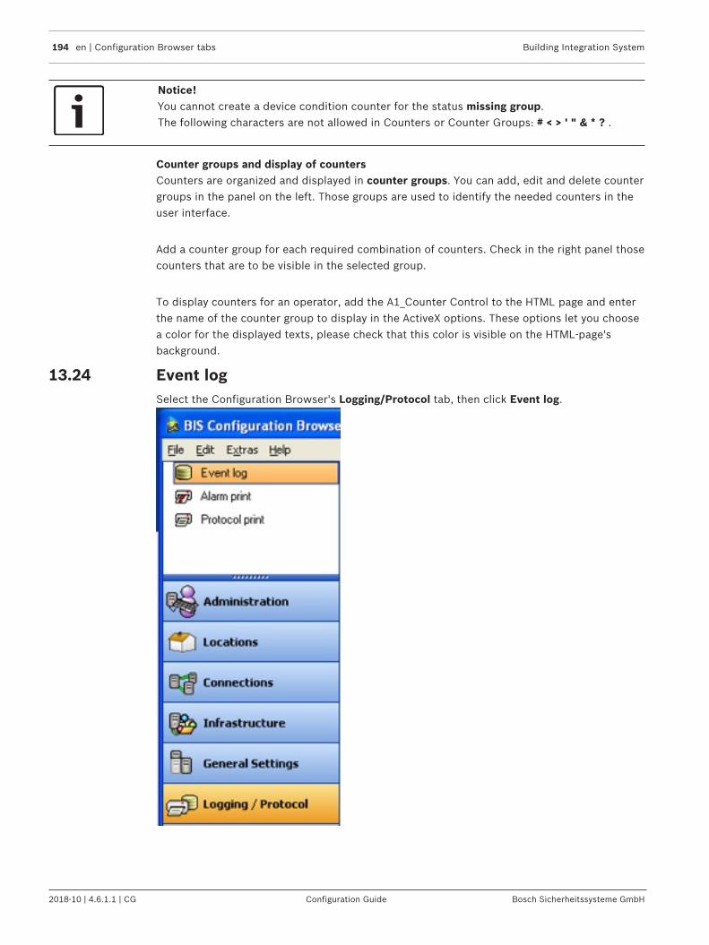
194 en | Configuration Browser tabs Building Integration System
2018-10 | 4.6.1.1 | CG Configuration Guide Bosch Sicherheitssysteme GmbH
Notice!You cannot create a device condition counter for the status missing group.The following characters are not allowed in Counters or Counter Groups: # < > ' " & * ? .
Counter groups and display of countersCounters are organized and displayed in counter groups. You can add, edit and delete countergroups in the panel on the left. Those groups are used to identify the needed counters in theuser interface.
Add a counter group for each required combination of counters. Check in the right panel thosecounters that are to be visible in the selected group.
To display counters for an operator, add the A1_Counter Control to the HTML page and enterthe name of the counter group to display in the ActiveX options. These options let you choosea color for the displayed texts, please check that this color is visible on the HTML-page'sbackground.
13.24 Event logSelect the Configuration Browser's Logging/Protocol tab, then click Event log.
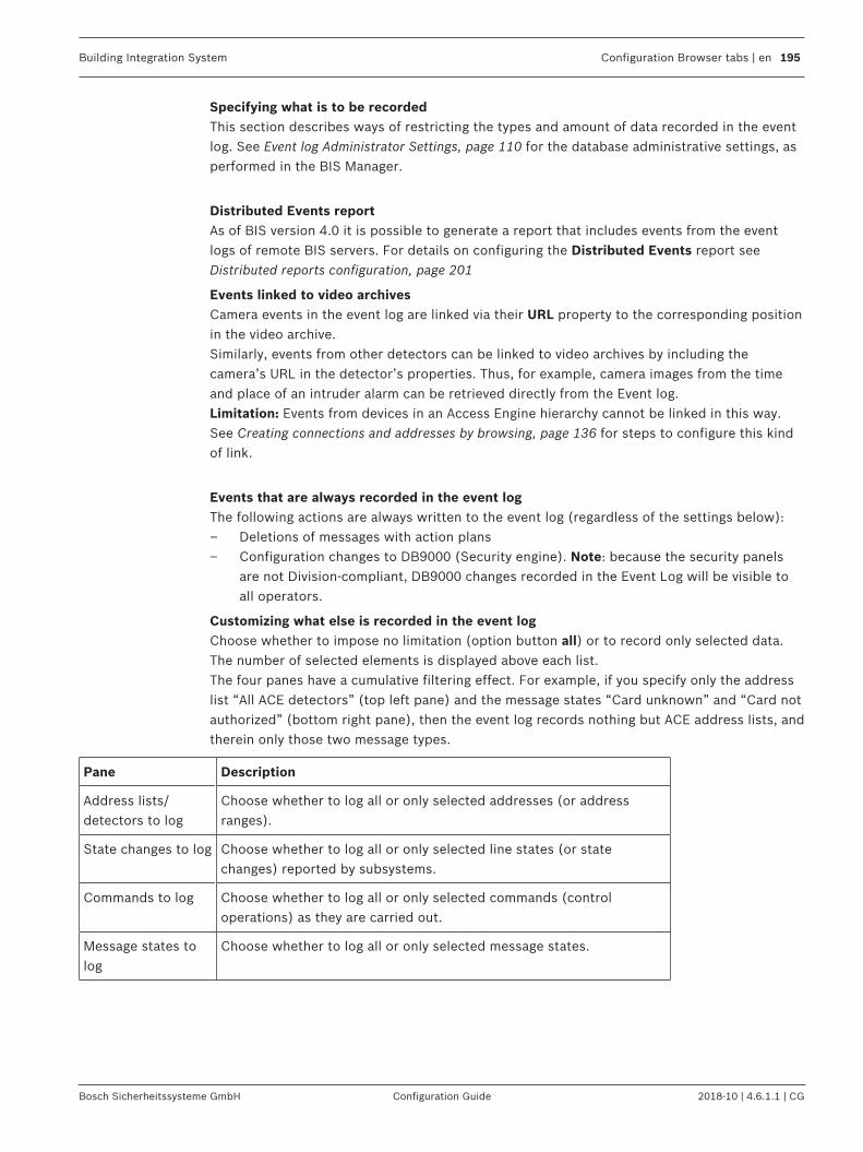
Building Integration System Configuration Browser tabs | en 195
Bosch Sicherheitssysteme GmbH Configuration Guide 2018-10 | 4.6.1.1 | CG
Specifying what is to be recordedThis section describes ways of restricting the types and amount of data recorded in the eventlog. See Event log Administrator Settings, page 110 for the database administrative settings, asperformed in the BIS Manager.
Distributed Events reportAs of BIS version 4.0 it is possible to generate a report that includes events from the eventlogs of remote BIS servers. For details on configuring the Distributed Events report seeDistributed reports configuration, page 201
Events linked to video archivesCamera events in the event log are linked via their URL property to the corresponding positionin the video archive.Similarly, events from other detectors can be linked to video archives by including thecamera’s URL in the detector’s properties. Thus, for example, camera images from the timeand place of an intruder alarm can be retrieved directly from the Event log.Limitation: Events from devices in an Access Engine hierarchy cannot be linked in this way.See Creating connections and addresses by browsing, page 136 for steps to configure this kindof link.
Events that are always recorded in the event logThe following actions are always written to the event log (regardless of the settings below):– Deletions of messages with action plans– Configuration changes to DB9000 (Security engine). Note: because the security panels
are not Division-compliant, DB9000 changes recorded in the Event Log will be visible toall operators.
Customizing what else is recorded in the event logChoose whether to impose no limitation (option button all) or to record only selected data.The number of selected elements is displayed above each list.The four panes have a cumulative filtering effect. For example, if you specify only the addresslist “All ACE detectors” (top left pane) and the message states “Card unknown” and “Card notauthorized” (bottom right pane), then the event log records nothing but ACE address lists, andtherein only those two message types.
Pane Description
Address lists/detectors to log
Choose whether to log all or only selected addresses (or addressranges).
State changes to log Choose whether to log all or only selected line states (or statechanges) reported by subsystems.
Commands to log Choose whether to log all or only selected commands (controloperations) as they are carried out.
Message states tolog
Choose whether to log all or only selected message states.

196 en | Configuration Browser tabs Building Integration System
2018-10 | 4.6.1.1 | CG Configuration Guide Bosch Sicherheitssysteme GmbH
See also– Creating connections and addresses by browsing, page 136
13.25 Alarm printSelect the Configuration Browser's Logging/Protocol Outlook button, then click Alarm print.

Building Integration System Configuration Browser tabs | en 197
Bosch Sicherheitssysteme GmbH Configuration Guide 2018-10 | 4.6.1.1 | CG
Document printers are graphic-capable printers (not line printers) that print out messagesand associated floor plans for operators.
Using the New and Modify buttons in the top pane, enter the full UNC path (e.g. \\MyServer\MyPrinter ) of each printer to be used for alarm printing. IMPORTANT: make sure that thepath(s) that you enter here are known only to those client computers that are reallyintended for alarm printing.For each printer, state which message should cause the printout of its associated floor plan,and whether the printout should occur upon arrival or upon acknowledgement of the message.

198 en | Configuration Browser tabs Building Integration System
2018-10 | 4.6.1.1 | CG Configuration Guide Bosch Sicherheitssysteme GmbH
In the bottom box, specify the template for manual printing.Templates are stored in the directory<INST_DIR>\Customer_Configuration\<MyConfig>\Printouts.Where <MyConfig> should be replaced by the directory name of the desired configuration.
Notice!Some HTML editors write a <!doctype ....> statement as first line in any opened HTMLdocument. In this case, BIS displays scroll bars in the Alarm Print - to remove them, deletethe doctype line in the HTML document.
13.26 Protocol printSelect the Configuration Browser's Logging/Protocol Outlook button, then click Protocolprint.
To configure the line printers that are to print a protocol of system events, proceed asfollows:
Enter the full UNC path (e.g. \\MyServer\MyPrinter ) of the printer(s) to be used in the topbox. Then select the events that are to trigger a protocol print. You can choose between thefollowing modes:– Impose no restrictions - select the radio-button all, or– Assign only certain elements by clicking on the appropriate check boxes. In this case you
are shown how many elements you have selected.

Building Integration System Configuration Browser tabs | en 199
Bosch Sicherheitssysteme GmbH Configuration Guide 2018-10 | 4.6.1.1 | CG
Notice!Protocol printing is designed to work only with line printers, not inkjet or laser printers.Note that printers may print more slowly than messages arrive: In the printer's Advancedproperties select the radio button: Spool print documents so program finishes printingfaster to ensure that the printer can buffer its inputs and will not hold up the entire system incase of a printer fault.
Possible Entries for the events to print
Pane Description
Address lists/detectors to log
Choose whether to log all or only selected addresses (or addressranges).
State changes to log Choose whether to log all or only selected line states (or statechanges) reported by subsystems.
Commands to log Choose whether to log all or only selected commands (controloperations) as they are carried out.
Message states tolog
Choose whether to log all or only selected message states.
Notice!If one of the following OPC attributes are set to the value 1, protocol print will occur even ifno address lists, state changes, controls or message conditions are defined for protocol print:ADI Print – state no. 5008Update – state no. 5002
13.27 ToolsIn the Configuration Browser, click the Outlook button Tools.

200 en | Configuration Browser tabs Building Integration System
2018-10 | 4.6.1.1 | CG Configuration Guide Bosch Sicherheitssysteme GmbH
13.27.1 Engine-specific toolsDepending on which BIS Engines are installed, the menu will contain different configurationtools.E.g. for Access Engine:– ACE Badge designer– ACE Configuration Import/Export– ACE System Parameter Editor– ACE Configuration Card Personalization– ACE Configuration AMC IP addresses
E.g. for Video Engine:– VIE Configuration
Select the desired tool and click the start button which appears in the main window pane.Help on each of these configuration tools is available from the engine-specific modules in thisonline help.

Building Integration System Configuration Browser tabs | en 201
Bosch Sicherheitssysteme GmbH Configuration Guide 2018-10 | 4.6.1.1 | CG
13.27.2 Remote site configurationIntroductionThis tool is provided as of BIS Version 4.0 for the configuration of Multi-Server BIS systems. Inparticular the tool is used for creating the encrypted configuration files for Provider servers,that is, servers which make some or all of their addresses visible to Consumer servers.
Concepts and overviewFor the main concepts and an overview of BIS multi-server technology, see BIS multi-serversystems, page 11
Making a BIS server into a Provider serverFor the procedure to make a BIS server into a Provider Server, see Providing information toother BIS single server systems , page 92
13.27.3 Distributed reports configurationIntroductionThis tool is provided as of BIS Version 4.0 for the configuration of a special event log reportthat contains events from multiple networked BIS servers .Specifically the tool creates:– a local encrypted configuration file that contains information about all the remote BIS
servers that may contribute events to the Distributed Events report in the local event log.– a stored procedure, in your local Event log, that accesses the remote event logs.
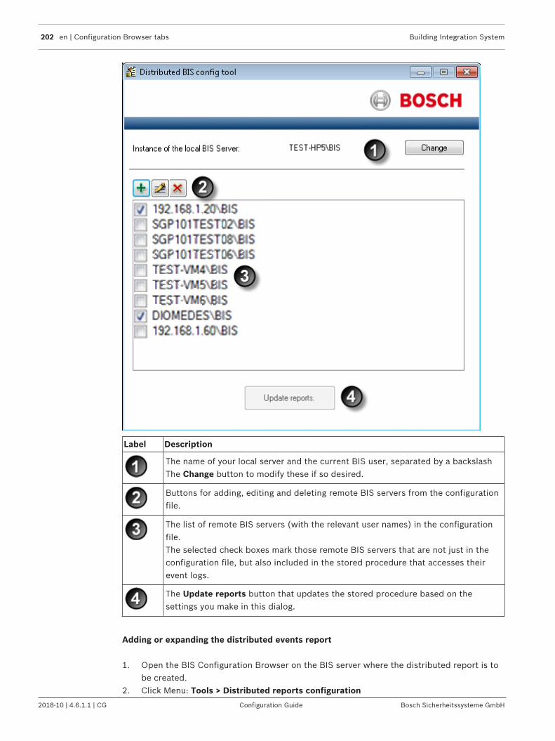
202 en | Configuration Browser tabs Building Integration System
2018-10 | 4.6.1.1 | CG Configuration Guide Bosch Sicherheitssysteme GmbH
Label Description
The name of your local server and the current BIS user, separated by a backslashThe Change button to modify these if so desired.
Buttons for adding, editing and deleting remote BIS servers from the configurationfile.
The list of remote BIS servers (with the relevant user names) in the configurationfile.The selected check boxes mark those remote BIS servers that are not just in theconfiguration file, but also included in the stored procedure that accesses theirevent logs.
The Update reports button that updates the stored procedure based on thesettings you make in this dialog.
Adding or expanding the distributed events report
1. Open the BIS Configuration Browser on the BIS server where the distributed report is tobe created.
2. Click Menu: Tools > Distributed reports configuration

Building Integration System Configuration Browser tabs | en 203
Bosch Sicherheitssysteme GmbH Configuration Guide 2018-10 | 4.6.1.1 | CG
3. In the main dialog pane, click the button Start the Configuration– Effect: The Distributed BIS config tool appears.– Note: if no configuration file as yet exists, then it will be created at this point. In this
case the list of servers: will be empty.
4. Click the (Add) button to add a remote server to the configuration file– Effect: A dialog box appears
5. Enter the name of the remote server (or its IP address) and a BIS operator name for thatremote server, using backslash as the separator, e.g. MYSERVER\BisUser1– Note: The operator needs to have administrator privileges
6. Either keep the default user credentials, or clear the check box and enter the user nameand password of your choice. Click Apply– Effect: The remote server is added to the list in the main dialog.– Effect; The remote server and username are verified and saved to the configuration
file.– Note: A server’s being in the list is necessary but not sufficient to share its event log.
It also needs to be included in the stored procedure that accesses remote eventlogs.
7. Back on the main Distributed reports configuration dialog repeat the previous steps toadd as many remote BIS servers as desired
8. Select the check boxes next to any servers whose event logs are to be included in thedistributed report.
9. Click the Update reports button. – Effect: Only those remote servers whose check boxes are selected are added to the
stored procedure that accesses remote event logs.
Modifying connection data for participating servers
1. Open the BIS Configuration Browser on the BIS server where the distributed report is tobe created.
2. Click Menu: Tools > Distributed reports configuration3. In the main dialog pane, click the button Start the Configuration
– Effect: The Distributed BIS config tool appears.4. Select the name (not the check box) of the server that you want to edit.
– Effect: The name of the server is highlighted in the list.
5. Click the (Edit) button to edit a remote server in the configuration file– Effect: A dialog box appears
6. Edit the Instance, user name and/or user credentials in the dialog box. Click Apply tosave changes.
7. Click the Update reports button. to save the changes to the stored procedure.
Procedures for restricting the distributed reportThere are two ways of doing this.

204 en | Configuration Browser tabs Building Integration System
2018-10 | 4.6.1.1 | CG Configuration Guide Bosch Sicherheitssysteme GmbH
Deactivating remote servers in the configuration file– To ensure that the events from a remote server are not included in the report, but still
keep the remote server in the list for possible future use, clear the relevant check box inthe server list on the Distributed reports configuration dialog, and click the Update
reports button.
Removing remote servers from the configuration file1. Alternatively, select the name (not the check box) of the server that you want to delete.
– Effect: The name of the server is highlighted in the list.
2. Click the (Delete) button to remove the remote server from the configuration fileand the stored procedure– Effect: You will be prompted to confirm the deletion. Click OK to do so– Effect: Your modifications to the configuration file and stored procedure are saved.

Building Integration System Glossary | en 205
Bosch Sicherheitssysteme GmbH Configuration Guide 2018-10 | 4.6.1.1 | CG
GlossaryActive Directory
A directory service that authenticates users,computers and other resources in a Windowsdomain-type network.
BIS server
(Hardware) A computer where the BIS applicationis installed. Also known as a Login server.
Connection server
(Hardware) A computer that runs OPC serversoftware with which external devicescommunicate by OPC protocol. The BIS setupprogram can be used to turn a Windows systeminto a potential Connection server.
Consumer server
(Hardware) The Consumer server is a BIS singleserver system that reads information from one ormore other BIS single server systems byconfiguring them as OPC servers.
Database server
(Hardware) A computer that hosts BIS databasesfor the event log and (optional) engines.
Layer
In the context of location plans a layer is a virtualstratum of information about the infrastructure ofa location in an AutoCAD file. See http://docs.autodesk.com .
Local Discovery Server
(Software) a Windows Service that is started byBIS and runs in the background to discover OPCUA servers available on the network.
Multi-server BIS system
A multi-server BIS system is one in which two ormore BIS single server systems share information.BIS multi-server systems can be organized ashierarchical or peer-to-peer networks.
OPC client
A software program that reads datacommunications in OPC protocol written by OPCservers.
OPC server
A software program that converts the hardwarecommunication protocol used by a device into theOPC protocol.
OPC UA
OPC Unified Architecture (OPC UA) is anenhanced OPC protocol from the OPCFoundation. It provides better platformindependence, scalability and data security thanits predecessors.
Plot template
In the context of location plans a plot template isan object from which individual plots inheritcertain attributes. See http://docs.autodesk.com .
Provider server
(Computer) The Provider server is a BIS singleserver system that provides information to otherBIS single server systems via OPC.
Remote Sites Connector
The Remote Sites Connector (RSC) is an OPCserver program running on the Consumer server.It maintains multiple remote sites connections.Multiple Remote Sites Connectors may runsimultaneously on a single Consumer server.Separate Remote Sites Connectors are a way ofgrouping remote sites connections and insulatingthem from each other.
Single server BIS system
A single server BIS system contains only one BISLogin server (also known as the BIS server). Itmay run OPC server software itself, and maycontain zero or more Connection server andDatabase server computers.
xref
In the context of location plans an xref is adrawing file referenced by another drawing

206 en | Glossary Building Integration System
2018-10 | 4.6.1.1 | CG Configuration Guide Bosch Sicherheitssysteme GmbH

Building Integration System Index | en 207
Bosch Sicherheitssysteme GmbH Configuration Guide 2018-10 | 4.6.1.1 | CG
IndexAAction Buttons 80ActiveX controls 85Address Lists 167Alarm print 196Application Launcher 159Associations 173Authentication 77Authorizations 118Automatic Backup of Event Log 183
BBacking up the configuration 187
Automatic (scheduled) backup 189Manual backup 188
Backup-Restore 112BIS Manager 103
CClientInfo Tool 100Configuration Printouts 40Connection server 117Customizing Buttons 19
DDB Migration 107Demo Mode 115Detector data 51Detector Placement 141Detector Type 149Device Condition Counters 192Diagnostic Tools 51Dialog field 14Divisions 129Dual authorization 120
EError Log 113Event Log 105, 194Event Simulation 51Exporting detector data 51
FFilling-Organizing Data 52FrontPage 82
JJavaScript 87Job 175
LLayout 14License 113
Load-Save Configuration 113Location Tree 87Login 32Logoff
Immediate operator logoff 36Postponed operator logoff 36
Deferred operator logoff 36
MMessage Distribution 179Message Generation 180Multi-server BIS
Configuring Consumer servers 95Configuring Provider servers 92Creating the configuration file for the Provider
server 93Examining the final list of addresses marked for
export to the configuration file 94Reading and modifying existing configuration files 94
NNetLimiter Tool 99New Configuration 35
OOPC connections 139OPC server 45Operators 124
PPassword 32Protocol Print 198
SServer Structure 116Start Configuration 31Start the BIS Configuration Browser 29Start-Stop System 26States 145Status bar 14Symbols 20Symbols blinking 157System Start-Stop 103
TTimeouts 179Timer 170Title bar 14Tool bar 14Transmit Message 105Tree structure 130

208 en | Index Building Integration System
2018-10 | 4.6.1.1 | CG Configuration Guide Bosch Sicherheitssysteme GmbH
Trigger 175Typical Associations 182
VVersion 114Virtual Device 160
WWindows Authentication 77


Bosch Sicherheitssysteme GmbHRobert-Bosch-Ring 585630 GrasbrunnGermanywww.boschsecurity.com© Bosch Sicherheitssysteme GmbH, 2018