BUILDING INFORMATION MODELING SCOPE OF SERVICES … · 12/11/2010 · 3.1.1 Architectural ......
36
BUILDING INFORMATION MODELING SCOPE OF SERVICES AND REQUIREMENTS FOR DESIGN/BUILD Final – November 12, 2010
Transcript of BUILDING INFORMATION MODELING SCOPE OF SERVICES … · 12/11/2010 · 3.1.1 Architectural ......

BUILDING INFORMATION MODELING SCOPE OF
SERVICES AND REQUIREMENTS FOR
DESIGN/BUILD
Final – November 12, 2010
TABLE OF CONTENTS
Page
-i-
1. Introduction ...................................................................................................................... 1
1.1 Statement of Purpose ........................................................................................... 1
1.2 Building Information Model ............................................................................... 1
1.3 BIM Competence and Responsibilities .............................................................. 1
1.4 Data Ownership and Reuse ................................................................................. 2
1.5 Relationship of BIM Requirements to other Requirements ............................ 2
2. Model Communication and Accessibility ...................................................................... 2
2.1 Security ................................................................................................................. 2
2.2 NASA Review ....................................................................................................... 3
2.3 NASA Interaction................................................................................................. 3
2.3.1 Commissioning .......................................................................................... 3
2.3.2 Facility Management ................................................................................. 3
2.3.3 Reviews ...................................................................................................... 4
2.3.4 Export information ..................................................................................... 4
3. BIM Functional Requirements ....................................................................................... 4
3.1 Models ................................................................................................................... 4
3.1.1 Architectural .............................................................................................. 4
3.1.2 Furniture, Furnishings and Equipment (FF&E) ......................................... 4
3.1.3 Structural .................................................................................................... 5
3.1.4 Mechanical ................................................................................................. 5
3.1.5 Electrical .................................................................................................... 5
3.1.6 Plumbing .................................................................................................... 5
3.1.7 Telecommunications / Information Technology ........................................ 6
3.1.8 Life Safety and Fire Protection .................................................................. 6
3.1.9 Underground Utilities (Civil) ..................................................................... 6
3.1.10 Site / Campus (Civil and Landscape)......................................................... 6
3.2 Program Space Validation .................................................................................. 7
3.3 DESIGN Coherence ............................................................................................. 7
3.3.1 General ....................................................................................................... 7

TABLE OF CONTENTS
(continued)
Page
-ii-
3.3.2 Minimum Requirements for Spatial Coordination and Clash
Detection .................................................................................................... 9
3.4 Code Review ....................................................................................................... 10
3.5 NASA Building Requirements .......................................................................... 10
3.6 Analysis and Optimization ................................................................................ 10
3.6.1 Lighting and Daylighting ......................................................................... 10
3.6.2 Energy ...................................................................................................... 10
3.6.3 Carbon ...................................................................................................... 11
3.6.4 Wind ......................................................................................................... 11
3.6.5 Water ........................................................................................................ 11
3.6.6 Indoor Air Quality.................................................................................... 11
3.6.7 Acoustics .................................................................................................. 11
3.6.8 Functional Analysis per Building Type ................................................... 12
3.7 Construction Document Drawings ................................................................... 12
3.8 Contractor BIM Model During Construction ................................................. 12
3.8.1 Scheduling................................................................................................ 12
3.8.2 LEED or other Environmental Certification ............................................ 13
3.8.3 Construction management ....................................................................... 13
3.8.4 Record BIM ............................................................................................. 14
4. BIM Execution Plan (BEP) ........................................................................................... 15
4.1 BIM Staffing Plan .............................................................................................. 15
4.2 Security Plan....................................................................................................... 16
4.3 Model Progression Matrix ................................................................................ 16
4.4 BIM Process Design ........................................................................................... 16
4.5 Schedule .............................................................................................................. 16
4.6 Model Structure ................................................................................................. 17
4.6.1 File Naming Structure .............................................................................. 17
4.6.2 Model Structure and Division of Modeled Information .......................... 17
4.6.3 Measurement and Coordinate Systems .................................................... 18
4.7 Software and Operating Systems ..................................................................... 18

TABLE OF CONTENTS
(continued)
Page
-iii-
4.8 Electronic Communication Procedures ........................................................... 18
4.8.1 File Access and Archiving ....................................................................... 18
4.8.2 Electronic file formats and use. ............................................................... 19
4.8.3 Contractor Information Manager(s) ......................................................... 19
4.9 Pre-Design Site Survey Modeling ..................................................................... 19
4.10 Change Management ......................................................................................... 20
4.11 Construction Management ................................................................................ 20
4.12 Facility Management ......................................................................................... 21
5. Interoperability .............................................................................................................. 21
5.1 BIM Software ..................................................................................................... 21
5.2 Open Source File Formats/Open Standards ................................................... 22
5.2.1 Statement of Principal .............................................................................. 22
5.2.2 Current Version IFC Model View Definition (MVD) Formats: .............. 24
5.2.3 Portable Document Format: ..................................................................... 24
5.2.4 GBxml ...................................................................................................... 24
5.2.5 COBie2 .................................................................................................... 23
5.2.6 FM/BAS Integration Export .................................................................... 23
6. Record Model ................................................................................................................. 24
6.1 Objectives............................................................................................................ 24
6.2 Requirements...................................................................................................... 24
6.3 Facility Management Information .................................................................. 25
7. Modeling Requirements ................................................................................................ 25
7.1 General ................................................................................................................ 26
7.2 Types of Model Elements .................................................................................. 26
7.3 Model Geographical Location .......................................................................... 26
7.4 Points of Reference ............................................................................................ 27
7.5 Requirements for Modeling Space ................................................................... 28
7.6 Space Naming and Coding ................................................................................ 28
7.7 Requirements for Record BIM and Facility Management Information ...... 29

TABLE OF CONTENTS
(continued)
Page
-iv-
7.8 Contractor BIM Deliverables ........................................................................... 29
7.8.1 Models...................................................................................................... 29
7.8.2 Data Deliverables ..................................................................................... 30
7.8.3 2D Deliverables ....................................................................................... 30
7.8.4 Digital Deliverables ................................................................................. 30
8. Waivers of Specific Requirements ................................................................................ 30
9. Abbreviations List .......................................................................................................... 31
1. INTRODUCTION
This document defines the Design-Builder (“Contractor”) scope of work and deliverables
for using Building Information Modeling on NASA projects delivered using a design construct
methodology. If attached to a Request for Proposal for Design-Build Services, the Contractor’s
response should include the below tasks and deliverables within its proposal. If attached to the
Contractor's contract for services, the tasks and deliverables required by this document become
an integral part of the Contractor's contract for services. Services and deliverables must comply
with NASA Facility Project Requirements NPR 8820 and _____________________ .[insert
center design requirements, e.g. APD/APR 8829.1 for Ames] Statement of Purpose
1.1 Statement of Purpose
If used effectively BIM provides opportunities to improve facility quality while
maintaining or reducing facility cost. In addition, BIM creates opportunities for reusing data for
multiple purposes, including NASA’s operation and maintenance of its facilities. To achieve
these ends, the BIM must be structured to achieve the required purposes. This document
describes NASA’s requirements for use of Building Information Models (BIM) in the design and
construction of its facilities.
1.2 Building Information Model
“Building Information Model” (BIM) or “Model” is a parametric, computable
representation of the project design developed by the Contractor, its consultants, and any
design/build subcontractors, and includes construction details developed by the Contractor and
its respective consultants and subcontractors that are integrated into the model. As used in this
BIM Specification, references to Building Information Model, BIM, or the Model, include the
primary design model or models and all linked, related, affiliated or subsidiary models developed
for design, analysis, estimating, detailing, fabrication, construction, operation or maintenance of
the project, or any portion or element of the project, whether the model is prepared by Contractor
or prepared by Contractor’s subcontractors or consultants.
1.3 BIM Competence and Responsibilities
The architects, engineers, designers and technicians involved with providing
services under Contractor’s Agreement, must be trained and experienced in using BIM
technology and processes. Unless BIM software is being provided by NASA, Contractor must
have, or must obtain at its own cost, sufficient software licenses and computer hardware to

- 2 -
adequately perform the services required.
Contractor will provide NASA with a detailed written description of the BIM
experience of its key project team members. At a minimum, the key project team members
include the principal project designer, the design discipline lead designers, the construction
project manager, the construction cost estimator, scheduling engineer, construction project
engineer and construction superintendent. In addition, Contractor will designate a BIM Manager
to oversee the technical aspects of developing, managing and maintaining the BIM model.
Contractor’s proposal will describe the BIM experience and responsibilities of these key
personnel on at least three prior projects that are similar to the current project in size and
complexity. The proposal will also describe how their prior BIM experience relates to specific
BIM deliverables and tasks within the Contractor’s scope of work or proposal.
1.4 Data Ownership and Reuse
NASA owns the BIM, the data contained within it, and all copyrights to the BIM.
If portions of the BIM are not authored by Contractor, Contractor will arrange by contract to
have the ownership and copyright to those portions exclusively assigned to NASA.
1.5 Relationship of BIM Requirements to other Requirements
The BIM developed by the Contractor must satisfy the requirements of the
Request for Proposal, NASA Facility Project Requirements, this BIM Specification, and any
additional requirements noted in the Contract. To the greatest extent practicable, the BIM should
describe the project as it will be constructed, with the exception of elements that can not be
practicably modeled because of software limitations or that are smaller than elements normally
modeled on similar projects. All limitations to the extent of modeling must be identified in the
BIM Execution Plan (Section 3) and agreed in writing by the NASA Contracting Officer. Those
project elements that are not modeled will be constructed in accordance with supplementary
design information prepared by Contractor that has been fully coordinated with the modeled
information.
2. MODEL Communication AND ACCESSIBILITY
2.1 Security
The NASA Contracting Officer will advise Contractor of the security
classification applicable to the BIM, including draft and related information. Contractor is
- 3 -
responsible for maintaining the security of the BIM, including access to the BIM, in accordance
with NASA regulations and guidelines. The obligation to keep the BIM secure continues
throughout performance of this contract and survives termination. At the conclusion of the
project, the BIM and all draft or related information will be given to NASA and any copies
destroyed in a manner appropriate for the security classification applicable to the information
and as required by NASA regulations.
2.2 NASA Review
The BIM must be reasonably available for NASA review and comment
throughout the project. The NASA Project Manager, and others designated by the Project
Manager shall be provided with secure access to the server or servers where the BIM is located
and with a reasonable method for providing comments regarding the BIM.
NASA’s right to review, and NASA’s review of the BIM is for NASA’s
convenience, alone, and does not create any duty for NASA to review the BIM or to take any
action upon reviewing the BIM, nor does it relieve Design/Builder of any of its responsibility for
complying with the terms of its contract, including its responsibility to properly design and
construct the project.
2.3 NASA Interaction
Contractor will maintain and administer the BIM and associated servers. The
contractor will provide BIM access to NASA and NASA contractors as designated by the NASA
Project Manager for the following purposes:
2.3.1 Commissioning
The NASA designated commissioning authority will be provided access to
the BIM and associated servers. The contractor will coordinate with the commissioning
authority the integration of model view definitions into the BIM
2.3.2 Facility Management
The NASA designated facility managers will be provided access to the
BIM and associated servers. The contractor will coordinate with the facility managers the
integration of model view definitions and the format and content of the record BIM.

- 4 -
2.3.3 Reviews
The NASA Project Manager and designated reviewers will be provided
access to the BIM and associated servers. The contractor will coordinate with the NASA project
manager and reviewers the use of the BIM for defined NASA reviews. The contractor will
enable NASA to document review comments into the BIM
2.3.4 Export information
NASA will be provided access to the BIM and associated servers for
exporting information. NASA reserves the right to utilize information exported from the BIM at
any time during the contract.
3. BIM FUNCTIONAL REQUIREMENTS
3.1 Models
The Contractor will provide a BIM of the following systems during design and construction. For
as-built model requirements refer to Section 6 of this building information modeling scope of
services and requirements for design/build document. The contractor(s) shall properly use
available “intelligent objects” to embody information about the building component
requirements and properties (e.g., material properties, functional information, dimensions,
uniformat assembly information, etc). The following sections describe more specific information
that shall be included in, but not limited to, the following models:
3.1.1 Architectural
The Contractor will provide a 3D BIM created with architectural
components that embody proper object information and parametric relationships in accordance
with good architectural practice. These components include, but not limited, to slabs/floors,
exterior and interior walls, roofs, doors, windows, stairs, railings, elevators, finishes, ceilings,
millwork and case goods.
3.1.2 Furniture, Furnishings and Equipment (FF&E)
The Contractor will provide a 3D BIM created with architectural
components that embody proper object information and parametric relationships in accordance
with good architectural practice. These components include, but are not limited to, furniture,
furnishings and equipment, including both Contractor furnished and Government furnished

- 5 -
items.
3.1.3 Structural
The Contractor will provide a 3D BIM created with structural components
that embody proper object information and parametric relationships in accordance with good
structural engineering practice. These components include, but are not limited to, all
substructure and superstructure components. The object information will include member profile
and dimension information.
3.1.4 Mechanical
The Contractor will provide a 3D BIM created with mechanical
components that embody proper object information and parametric relationships in accordance
with good mechanical engineering practice. These components include, but are not limited to, all
major mechanical equipment, cooling towers, chillers, air handling units, pumps, terminal boxes,
hydrants, HVAC piping and ductwork, hangers, and other HVAC equipment. Piping bends are
to be modeled for coordination with other trades.
3.1.5 Electrical
The Contractor will provide a 3D BIM created with electrical components
that embody proper object information and parametric relationships in accordance with good
electrical engineering practice. These components include, but are not limited to, all major
electrical equipment, transformers, switchgear, generators, panel boards, lights, conduit over 2"
(50.8mm) nominal O.D, hangers, cable trays, raceways and other electrical equipment. Conduit
bends are to be modeled for coordination with other trades.
3.1.6 Plumbing
The Contractor will provide a 3D BIM created with plumbing components
that embody proper object information and parametric relationships in accordance with good
mechanical engineering practice. These components include, but are not limited to, all major
plumbing equipment, fixtures, boilers, pumps, piping over 1 1/2" (38.1 mm) nominal O.D.,
hangers, and other plumbing equipment. Pipe bends are to be modeled for coordination with
other trades.

- 6 -
3.1.7 Telecommunications / Information Technology
The Contractor will provide a 3D BIM created with telecommunications
and information technology components that embody proper object information and parametric
relationships in accordance with good engineering practice. These components include, but are
not limited to, all major equipment, MDFs, IDFs, panel boards, conduit over 2" (50.8mm)
nominal O.D., hangers, cable trays, raceways and other equipment. Conduit bends are to be
modeled for coordination with other trades.
3.1.8 Life Safety and Fire Protection
The Contractor will provide 3D BIMs created with life safety and fire
protection components that embody proper object information and parametric relationships in
accordance with good mechanical and electrical engineering practice. These components
include, but are not limited to, fire detection devices, fire alarm devices, fire alarm panels, the
main sprinkler piping risers and related devices piping 1 ½” (38.1mm)or larger nominal O.D.,
sprinkler heads, control valves, fire suppression equipment, pumps, hangers, and other
equipment. Pipe bends are to be modeled for coordination with other trades.
3.1.9 Underground Utilities (Civil)
The Contractor will provide a 3D BIM for underground utilities created
with civil components that embody proper object information and parametric relationships in
accordance with good civil engineering practice. These components include all underground
utilities, piping, duct banks, vaults, manholes, hand holes, location of soil borings with
associated data and other civil features.
3.1.10 Site / Campus (Civil and Landscape)
The Contractor will provide 3D BIMs for site and campus design with
both civil and landscape components that embody proper object information and parametric
relationships in accordance with good civil engineering and landscape architecture practice.
These components include, but not limited to, topographic grading, streetscape, landscape
including hardscape, trees, planting stock (including roof), storm water drainage features (such
as catch basins and drain inlets), exterior lighting, and other site and campus features.
3.2 Program Space Validation

- 7 -
The Contractor will use the BIM Authoring software or other analysis tools to
compare and validate stated space program requirements provided by NASA. The space
validation will be based on the NASA NPR 8800.15, _________________________ [insert
NASA center design requirements], OmniClass Space and Facility Types Table and/or
BOCA/IFMA Standards. The comparison and validation will include space allocations,
adjacencies, and affinities.
The following will be developed automatically from the building information
model.
Assignable Areas (ASF) and Non-assignable Areas (NaSF) measured to
inside face of wall objects and designated boundaries of areas.
Gross Area (GSF) measured to the outside face of wall objects.
3.3 Design Coherence
3.3.1 General
It is the Contractor's responsibility to conduct and manage an adequate and
thorough Clash Detection process so that interferences between building components will have
been detected and resolved before construction. It will be the goal of the Contractor to eliminate
changes during construction due to major building interferences to zero.
The Contractor’s BIM Manager will assemble a composite model from all
of the model parts of each design discipline for the purpose of performing a visual check of the
building design for spatial and system coordination. Vertical shafts should also be reviewed to
ensure that adequate space has been allocated for all of the vertical mechanical systems and that
all of the shafts line up floor to floor. The clash detection process should uncover and address
hard clashes between modeled elements and soft clashes, such as infringements into code or
maintenance required clearances and necessary clearances for fireproofing, insulation or other
non-modeled elements. Prior to each scheduled coordination meeting, an updated clash report
will be issued by the BIM Manager to technical and engineering subcontractors.
Contractor will use coordination software for assembling the various
design models to electronically identify, collectively coordinate resolutions, and track and
publish interference reports between all disciplines. The Contractor will be responsible for
updating their models to reflect the coordinated resolution.
- 8 -
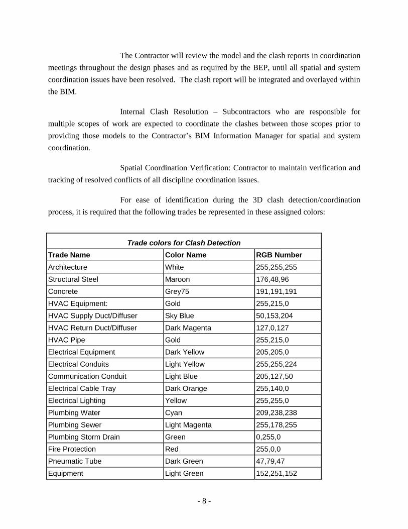
The Contractor will review the model and the clash reports in coordination
meetings throughout the design phases and as required by the BEP, until all spatial and system
coordination issues have been resolved. The clash report will be integrated and overlayed within
the BIM.
Internal Clash Resolution – Subcontractors who are responsible for
multiple scopes of work are expected to coordinate the clashes between those scopes prior to
providing those models to the Contractor’s BIM Information Manager for spatial and system
coordination.
Spatial Coordination Verification: Contractor to maintain verification and
tracking of resolved conflicts of all discipline coordination issues.
For ease of identification during the 3D clash detection/coordination
process, it is required that the following trades be represented in these assigned colors:
Trade colors for Clash Detection
Trade Name Color Name RGB Number
Architecture White 255,255,255
Structural Steel Maroon 176,48,96
Concrete Grey75 191,191,191
HVAC Equipment: Gold 255,215,0
HVAC Supply Duct/Diffuser Sky Blue 50,153,204
HVAC Return Duct/Diffuser Dark Magenta 127,0,127
HVAC Pipe Gold 255,215,0
Electrical Equipment Dark Yellow 205,205,0
Electrical Conduits Light Yellow 255,255,224
Communication Conduit Light Blue 205,127,50
Electrical Cable Tray Dark Orange 255,140,0
Electrical Lighting Yellow 255,255,0
Plumbing Water Cyan 209,238,238
Plumbing Sewer Light Magenta 255,178,255
Plumbing Storm Drain Green 0,255,0
Fire Protection Red 255,0,0
Pneumatic Tube Dark Green 47,79,47
Equipment Light Green 152,251,152

- 9 -
Trade colors for Clash Detection
Trade Name Color Name RGB Number
Gas Light Green 152,251,152
Security Systems Orange 255,165,0
Fire Alarm Fuchsia 255,0,255
3.3.2 Minimum Requirements for Spatial Coordination and Clash Detection
Architecture + Structural: Below-grade spaces, proposed floor plates with
major penetrations, floor-to-floor heights, beam clearances, heavy utilities locations, floor loads,
core, and vertical shafts, beam depths and required clearances, slab thickness, columns, column
caps, and structural bracing including seismic. Provide adequate space for construction and
maintenance access to structural elements, building equipment, and distribution systems.
MEPF (internal): Clash detection for MEPF elements.
Architecture + MEPF: Structural and space elements, flow and isolation
requirements, proposed functional area configurations, floor-to-floor heights, fire containment,
vertical and horizontal transportation. Possible NASA defined future expansions will be
considered and will be clash-free.
MEPF/HVAC + Architecture, Structure, and Telecommunications: Main
distribution and collection systems, configurations and sizes for piping, duct, conduit, power
wiring, blowers; diffusers; intakes, large compressors, hangers. Clearance reservations for
equipment maintenance filter removal, and equipment removal and replacement will be modeled
with the equipment, and sign-off on the adequacy of the space reservations will be obtained from
NASA.
Architecture + Life Safety Fire Protection: Safe zone and fire suppression
pipe and hanger location, egress paths and exit distance requirements, equipment, and pipe
penetrations.
Architecture/HVAC + Interiors: Merges will include ductwork and piping
+ ceilings and FF&E + HVAC.,
Space Validation: There will be no space gaps. Bounding boxes,
designated enclosed floor areas, used to represent room and zone spaces will match with
- 10 -
architectural requirements and data values, and all will be coordinated with values given in the
program and engineering requirements as defined in the PER.
General Model Quality Checking: All walls will be properly joined to
prevent “space leaks” in areas defined by enclosing walls. Bounding boxes will not conflict.
Security setbacks + structure + site: Include line of site coherence check
for allowance of security zone as defined by NASA security criteria.
Accessibility Compliance: Wheelchair pathways and clearances +
structure + MEPF components. These components will include plumbing fixtures. (If using
Solibri Model Checker or other rules-based model checking software, accessibility compliance
can be checked automatically.
3.4 Code Review
The Contractor will use the BIM Authoring software or model checking software
to validate the design is in compliance with stated building code requirements.
3.5 NASA Building Requirements
The Contractor will use the BIM Authoring software or other analysis tools to
validate the design is in compliance with stated NASA building requirements.
3.6 Analysis and Optimization
3.6.1 Lighting and Daylighting
Lighting and Daylighting simulation and calculations will be based on
information within or extracted directly from BIM and validated by lighting and daylighting
modeling. The model elements will be created to a level of completeness and quality as required
to perform a lighting and daylighting analysis appropriate for the phase and decision
requirements of the project.
3.6.2 Energy
Energy simulation and life-cycle cost calculations will be based on
information within or extracted directly from BIM and validated by energy modeling. The model
elements will be created to a level of completeness and quality as required to perform an energy
analysis appropriate for the phase and decision requirements of the project.
- 11 -
3.6.3 Carbon
Carbon output calculations will be based on information within or
extracted directly from BIM and validated by energy modeling. The model elements will be
created to a level of completeness and quality as required to perform an energy analysis
appropriate for the phase and decision requirements of the project.
3.6.4 Wind
Wind simulation and calculations as wind affects structure and natural
ventilation assumptions and requirements will be based on information within or extracted
directly from BIM. The model elements will be created to a level of completeness and quality as
required to perform an analysis appropriate for the phase and decision requirements of the
project.
3.6.5 Water
Water use calculations will be based on information within or extracted
directly from BIM. The model elements will be created to a level of completeness and quality as
required to perform a water usage analysis appropriate for the phase and decision requirements
of the project.
3.6.6 Indoor Air Quality
Indoor Air Quality analysis will be based on information within or
extracted directly from BIM. The model elements, such as HVAC filters and finish surface
materials, will be created to a level of completeness and quality as required to perform an air
quality analysis appropriate for the phase and decision requirements of the project.
3.6.7 Acoustics
Acoustic simulation and calculations to test and verify compliance with
stated program acoustical requirements will be based on information within or extracted directly
from BIM. The model elements will be created to a level of completeness and quality as required
to perform an analysis appropriate for the phase and decision requirements of the project.
3.6.8 Functional Analysis per Building Type
Utilize the BIM to analyze and forecast interior and exterior pedestrian

- 12 -
circulation and activity patterns within the project parameters. Life safety egress, accessibility
requirements for Federal properties and wayfinding will be included in the analysis.
Utilize the BIM to analyze and forecast vehicular circulation and activity
patterns within the project parameters. Parking, fire department vehicles access, accessibility,
deliveries and trash removal and material handling processes will be included in the analysis.
Utilize the BIM to analyze access for moving facility furniture, fixtures,
and equipment throughout the project parameters.
Utilize the BIM to analyze occupant access to facility furniture, fixtures,
and equipment throughout the project parameters.
3.7 Construction Document Drawings
Contractor will produce construction document drawings utilizing IFC compliant
BIM Authoring software. All drawing information, including 2D plans, elevations, sections,
schedules and details, needed to describe the design intent for subcontractor bidding will be
graphically or alphanumerically included in and derived from models created in the BIM
Authoring software. All 2D drawings must comply with the graphic standards as referenced in
NASA Facility Project Requirements, NPR 8820, and any Center specific standards..
3.8 Contractor BIM Model During Construction
3.8.1 Scheduling
Reviews of the BIM during construction will be part of the required
construction meetings. The BIM reviews will be included in the contractor’s construction
meeting agenda. The BIM reviews will include clash detection, model view definitions and
facility management requirements integration
The BIM must be linked to Design/Builder’s digital critical path method
(“cpm”) approved baseline construction schedule and subsequent cpm schedule updates to allow
simulation of the construction phasing and sequencing. At a minimum, the digital schedule
should link to the following modeled systems:
3.8.1.1 Structural: All structural framing components including
foundations, grade beams, columns, load bearing walls, floor and roof decks and supports;

- 13 -
3.8.1.2 Exterior Building Envelope: Stud walls, Exterior panels and
assemblies, curtain walls, openings, and glazing;
3.8.1.3 Interior partitions: Main plumbing walls and wall assemblies;
3.8.1.4 Mechanical systems: Main duct work and equipment (separated
by floors);
3.8.1.5 Roof systems: Roof assemblies, major roof mounted equipment,
openings;
3.8.1.6 Plumbing: Main connection lines from site, main plumbing
lines;
3.8.1.7 Sitework: Excavation work, footings, foundations, on-grade
slab; and
3.8.1.8 Site Logistics: Site layout, safety access; material storage;
coordination.
3.8.2 LEED or other Environmental Certification.
3.8.2.1 Documentation
If the project requirements include designing and constructing
the project to meet the requirements of USGBC LEED™, Green Globes™, Energy Star or
similar environmental guidelines or standards, Design/Builder will develop and organize the
BIM to incorporate information necessary for submission to the certifying or reviewing agency.
Design/Builder will review the reports required for the relevant environmental submission and
structure the BIM to facilitate creating or exporting these reports.
3.8.3 Construction management
3.8.3.1 Submittals
In addition to any other requirements of the Contract
Documents, submittals should be provided as:
3.8.3.1.1 Manufacturer’s model elements that are
interoperable with the BIM and provided by the manufacturer or vendor of materials, equipment
- 14 -
or systems;
3.8.3.1.2 Custom created model elements prepared by the
Design/Builder or its subcontractors that are interoperable with the BIM and model portions of
the project, specific installations or details or equipment;
3.8.3.1.3 Fabrication or detail models that are prepared by
Design/Builder or its subcontractors. These fabrication or detail models must be in software that
is interoperable with the BIM or that can be compared to the BIM for clash detection or other
purposes through the use of viewing software that is interoperable with the BIM and the
fabrication or detail modeling software;
3.8.3.2 Change Orders
Design changes reflected in Change Orders approved by NASA
must be promptly incorporated into the BIM such that the BIM reflects the current approved
design. Design changes during construction must be clash-detected to determine the extent of
impact due to the changed design prior to approval of the Change Order.
3.8.3.3 Commissioning
In addition to any other requirements for commissioning
contractor will provide the follwing:
3.8.3.3.1 The contractor will coordinate with the
commissioning authority throughout construction to update the BIM with model view definitions
of the model elements.
3.8.3.3.2 The contractor will provide the commissioning
authority access to the BIM during construction to review and export out model information.
3.8.4 Record BIM
The BIM must be updated continuously throughout the construction
process and must include all addenda, approved change orders, field orders, clarifications, rfi
responses and as-built conditions. The Record BIM includes the BIM at a Level of Detail 500
and includes a description of the relationship of each model in the Record BIM to the others.
Contractor may reference the AIA Document E202 – 2008 for Level of Detail 500 description.
In addition, the Record BIM must be accompanied by the final versions of all fabrication and

- 15 -
detailing models prepared by Design/Builder and its subcontractors. All models must be
provided in native file format with a description of the software used to create the model
(software manufacturer, software name, version number, and operating system used for the
software.
4. BIM EXECUTION PLAN (BEP)
Within 30 days after execution of its Design-Build Agreement, Contractor will prepare a
BIM Execution Plan (BEP) confirming the intended uses of the BIM during both the design and
construction phases of the project, describing the communication paths, the model structure, the
Level of Detail of the modeled elements at each contractual milestone or deliverable, and the
BIM process design. The BEP will be provided to NASA for its review and approval. Once
approved, the BEP can not be modified without NASA's written approval.
The BEP will, at a minimum, contain the following elements.
4.1 BIM Staffing Plan
Contractor will identify for itself and each of its subcontractors and consultants,
the persons that within their organizations responsible for managing the BIM, or portion of the
BIM. Where an organization is responsible for multiple disciplines, or where the project is
divided into sections or phases, the BIM Staffing Plan should include the persons responsible for
the discipline, section or phase. For each person identified, the BIM Staffing Plan should include
the person's:
Name
Title
Contact Information (location, primary phone number, mobile phone number,
and email address)
Description of the duration and extent of the person’s experience with the
BIM software the Contractor proposes to use
Identification and description of prior projects where the person used BIM
software and the extent it was used on that project
Role (i.e, BIM structural design lead; BIM mechanical design leader, etc.)
Anticipated time devoted to the project in hours per week. If the level of
activity will vary throughout the project, th staffing plan should be delivered as
a schedule. This may be depicted on a monthly schedule basis where the
level of activity will vary during the project.

- 16 -
4.2 Security Plan
Contractor will prepare a Security Plan that describes the procedures and
safeguards used to preserve the confidentiality and integrity of the BIM and to demonstrate
compliance with NASA requirements for data security and integrity.
4.3 Model Progression Matrix
The BEP must contain a model progression matrix substantially similar to the
Model Progression Specification spreadsheet published by American Institute of Architects,
California Council or the Model Element Table, Section 4.2 of American Institute of Architect's
Document AIA E-202. The model progression matrix must be executed by each party that is
assigned responsibility as a model component author in the matrix. The phasing columns of the
matrix should be modified to match the phasing of project deliverables in the Contractor contract
and the Level of Detail (LOD) must comply with Uniformat II, Level 3 model components and
should include user level sub-categorization, (Uniformat Levels 4 & 5 if necessary to provide
appropriately defined LOD and model component author responsibility). The model progression
matrix must show the LOD that must be accomplished on or before the completion of each
phase, or the date of each contract deliverable or milestone, as identified in Contractor’s
agreement with NASA.
4.4 BIM Process Design
Contractor will lead a workshop that includes all design level participants,
including Contractor's staff, Contractor's consultants, and NASA staff. The purpose of the
workshop is to develop process diagrams documenting BIM information exchange and BIM
workflow. At a minimum, the process mapping should include a process map of the overall BIM
processes and individual detailed maps documenting the information and workflow applicable to
specific BIM uses. At the conclusion of the workshop, the Contractor will prepare the process
overview and detailed BIM process maps and distribute them to the workshop participants.
Examples of the BIM process design maps and supporting worksheets are contained in the BIM
Project Execution Planning Guide, published by the Penn State Computer Integrated
Construction Research Program.
4.5 Schedule
Contractor will prepare a schedule for BIM design deliverables tied to the Model
Progression Matrix. The schedule must include all BIM tasks of Contractor's consultants and

- 17 -
subcontractors, tasks of other NASA retained consultants who are contributing to the design, the
schedule of clash detection and resolution meetings, and appropriate review time by NASA or
other governmental agencies that will comment or render decisions regarding the project design.
The schedule will be submitted to NASA for review as directed by the contract documents.
4.6 Model Structure
4.6.1 File Naming Structure
File names for models should be formatted as discipline-project number-
building number.file extension. (Example: ARCH-1111-BL001.rvt) File name prefixes by
discipline are listed in the table below.
Model Designator
Architectural Model ARCH-
Civil Model CIVIL-
Mechanical Model MECH-
Plumbing Model PLUMB-
Electrical Model ELEC-
Structural Model STRUCT-
Fire Protection Model FP-
Furniture, Furnishings and Equipment (FF&E) Model
FFE-
Telecommunications / Information Technology Model
IT-
Energy Model ENERGY-
Coordination Model COORD-
Construction Model CONST-
Other Model Types as Required
4.6.2 Model Structure and Division of Modeled Information
In most instances, the BIM will consist of a series of related models that
depict information relevant to specific disciplines or uses. Moreover, a specific discipline model
or use model may be organized into separate floors, sections, divisions or files. The BEP must
describe the organization of the model files, explaining how each file and model is separated, the
file naming conventions that will be used for each file type, the relationship of files to each other,
and the process that Contractor will use to ensure that all of the models remain current and
- 18 -
consistent.
4.6.3 Measurement and Coordinate Systems
The measurement and coordinate systems are to be confirmed and
documented in the BEP for this project. The Contractor will provide the following
All measurements will be in units of measurement required by standards
applicable to the specific NASA center. Site plans and building models will be geo-referenced to
______________, North American Datum 1983.
4.7 Software and Operating Systems
The BEP must list the BIM software and computer operating system or systems to
be used by Contractor and its consultants for this project. The software and operating systems
should be identified by vendor, product name, version identifier, build identifier, patch number,
and data architecture (32bit/64bit). Listed software, and listed operating systems, can not be
changed or upgraded without NASA's written approval, which will not be granted unless
Contractor demonstrates that the change or upgrade will not affect the ability to use existing BIM
information or to reliably and accurately exchange BIM information with other listed software.
4.8 Electronic Communication Procedures
4.8.1 File Access and Archiving
The BEP will specify:
The physical and logical locations of BIM files and related electronic
information;
The protocols for archiving and disaster recovery;
The protocols for user access and file permissions;
The directory/subdirectory/file structure used to organize the BIM files and
related electronic information; and
The internet address and directory structure for a secure web site,
internet accessible project manager, or web portal used to store and
access BIM files.
Maintenance of BIM as-built information during construction
4.8.2 Electronic file formats and use.

- 19 -
The BEP will specify:
The types of digital information that will be transmitted between project
participants;
The acceptable methods of transmission;
The acceptable file format(s) to be used for the type of digital information.
4.8.3 Contractor Information Manager(s)
The BEP will identify and provide contact information for the persons
responsible for managing and executing the responsibilities of this section.
4.9 Pre-Design Site Survey Modeling
If the Contractor scope of services includes surveying the existing project site and
preparing a pre-design model of the existing facilities, the BEP will include the following:
Description of tasks and schedule for developing the pre-design model;
Description of recommended methodology for developing the existing site
information, such as:
Development of model based on as-built documents for facility;
Optical surveying facility to develop a new model or validate the accuracy
of existing information used to create a model;
Laser scanning all or a portion of the facility to develop new model or
validate the accuracy of existing information used to create a model;
or Combination of tasks or approaches to accomplish the goals.
If laser scanning is required or will be used by the Contractor, the BEP should
identify:
Primary and secondary objectives of laser scanning;
Areas of Interest;
Resolution requirements and measurement units;
Type of deliverable;
Control network or other dimensional control; and
Quality control procedures.
Contractor may reference the GSA BIM Guide Series 03, BIM Guide For 3D

- 20 -
Imaging in developing this portion of the BEP.
4.10 Change Management
The BEP should specify the process for integrating submittals, change orders, rfi
responses, clarifications and similar construction phase information into the BIM. The process
should describe:
Who is authorized to integrate the construction level information into the BIM;
How construction level information will be coordinated and clash detected
with the existing BIM information;
How changes to the BIM will be logged; and
How construction level information will be identified to distinguish it from
Design BIM information.
4.11 Construction Management
The Execution Plan will outline the strategy and schedule for utilizing BIM
Technology to execute construction related activities and project coordination. The Execution
Plan will address the following:
Constructability analysis with BIM
Animation/graphic showing installed major building equipment space
clearance reservations for operations, repair, maintenance, and replacement
Proposed trade coordination strategy (clash detection)
Proposed use of digital fabrication
Updating as-built conditions in Record BIM
Utilization of 4D scheduling and construction sequencing technology
List of sub-contractors using digital fabrication
Proposed BIM Software to be used by the builder and fabrication modelers
Strategy to assure all trade information is modeled and coordinated
Proposed sub-contractor BIM workshops and training integrated into project
schedule
Integration of construction changes and commissioning data into BIM
Strategy for COBIE5 integration and submittals
4.12 Facility Management
- 21 -
The BEP must specify a workflow to identify model elements that are significant
for operations and maintenance of the facility and to map data structures from NASA’s
Computerized Maintenance Management System (CMMS) and Computer Aided Facility
Management (CAFM) to Systems attributes of the identified model elements. Where the CMMS
and FMS data structure does not have a comparable attribute in a modeled element, the BEP
should define an additional custom model element attribute to provide congruent mapping to the
CMMS data structure.
The BEP should specify a workflow for transferring FM data from the BIM to the
CMMS either directly or through middleware.
5. INTEROPERABILITY
Contractor is responsible for selecting BIM software that is adequate for Contractor's
tasks. Moreover, Contractor must demonstrate that the software used by it and its consultants
can exchange BIM information reliably and accurately and can read and export BIM information
into open source file formats to the extent required in Section 5.2. NASA's listing of BIM
software is not a recommendation that any specific product or products be used, nor is it a
representation or warranty as to the adequacy of the software product or of its ability to exchange
BIM information reliably and accurately. Contractor must demonstrate, through the technical
specification of the software, that it can meet the required functional requirements, whether or
not the proposed software is listed below.
5.1 BIM Software
BIM software for NASA projects must support intelligent objects and parametric
relationships. The software must comply with current industry interoperability standards and be
usable in a collaborative environment. All software platforms used for NASA projects will be
compliant with:
The most current version of Industry Foundation Classes (IFC) file format
Commercially available collaboration software that provides interoperability
between the different software applications (see below).
Additional software not listed below may be found on the BuildingSMART
Alliance web site, http://www.buildingsmartalliance.org/

- 22 -
TYPE (These are general categories. Listed software can be used for more than one “Type.”)
SOFTWARE (no order of preference)
Planning/Preliminary Cost Estimates Onuma Planning System (OPS), DProfiler, Tokmo, CodeBook
Authoring – Design (Architecture, Structural)
Revit Architecture, Revit Structure, Bentley BIM, ArchiCAD, Tekla, Vectorworks
Authoring - MEPF (Engineering & Construction)
ArchiCAD MEP, Revit MEP, Bentley BIM, CAD-Duct, CAD- Pipe, AutoSprink, PipeDesigner 3D
Authoring – Civil Bentley Inroads and Geopak, Autodesk Civil 3D
Coordination (clash detection) NavisWorks Manage, Bentley Navigator, Solibri Model Checker, Horizontal Glue, EPM Model Server, BIMServer
4D Scheduling Synchro, Vico, NavisWorks Simulate, Primavera, MS Project, Bentley Navigator
5D Cost Estimating Innovaya, Vico, Tokmo
Specifications (Management software for linking data between BIM and specification editing software utilizing uniformat codes)
Speclink-e, E-Specs
Model Checking Validation, IFC File Optimizer
Solibri
Construction Operations Building Information Exchange (COBie2)
Tokmo,
3D CMMS/BAS Integration Software EcoDomus
Energy Analysis EcoDesigner, Ecotect, eQuest, Green Building Studio, EnergyPlus, Trane/Trace, DOE2
5.2 Open Source File Formats/Open Standards
5.2.1 Statement of Principal
To ensure the life-cycle use of NASA building information, NASA
requires that information supporting common industry deliverables be provided in existing open
standards, where available. For those contract deliverables whose open standard formats have not
yet been finalized, the deliverable will be provided in a mutually agreed upon format that allows
the re-use of building information outside the context of the proprietary BIM software. The
formats used will be specified in the BIM Execution Plan and will include, at a minimum, the
following standards:

- 23 -
5.2.2 Current Version IFC Model View Definition (MVD) Formats:
Coordination---This format will be required for all deliverables needed to
demonstrate the coordination of design disciplines prior to construction. In addition to the
Coordination View file(s), where required, the Contractor will provide a report highlighting
automatically detected (hard and soft) collisions and identifying those collisions that require
further work by the Contractor.
5.2.3 Portable Document Format:
Non-modeled information authored directly by the Contractor will be
transformed to PDF to allow selection of text within the document. Documents authored by
others, but used by the Contractor such as manufacturer product data sheets, will be provided the
format made available by the manufacturer or scanned as image-based PDF documents.
5.2.4 GBxml
At a minimum, Architectural, Mechanical and Electrical BIM software
must support accurate and reliable data export to GBxml for environmental analysis,
optimization, and sustainability classifications, such as LEED, Green Globes and EnergyStar.
5.2.5 COBie2
BIM authoring software must support data export and import from the
COBie2 table databases.
5.2.6 FM/BAS Integration Export
NASA currently uses Maximo by IBM as its primary Computerized
Maintenance Management System (CMMS). The Record BIM must map Maximo input fields as
required by this Specification to allow CMMS data export from the Record BIM into Maximo.
Mapping should follow the guidelines of USACE Engineer Research and Development Center,
COBie2 Data Import/Export Interoperability with the MAXIMO Computerized Maintenance
Management System, November 2008.
6. Record MODEL
6.1 Objectives
To create a BIM(s) that contains the actual population of critical architectural,
- 24 -
structural, mechanical, electrical, plumbing, and civil objects for building services such as Fire
and Life Safety, HVAC, Data/Communications, Security, and Lighting that may be utilized for
building design, construction, and operation.
To populate the critical mechanical, electrical, plumbing, and civil objects with
the appropriate performance requirements and as-built information. The object attribute
information that is captured will be used throughout the building lifecycle and potentially
integrated into NASA’s ArcGIS system as implemented at each NASA Center.
To create an accurate current-condition record of the existing building conditions.
6.2 Requirements
Contractor will update the BIM to accurately reflect all design and construction
changes from the final pre-construction DBIM submitted to NASA.
Contractor will create a Record Building Information Model that accurately
reflects “as-built” conditions for all building systems including but not limited to, architectural,
civil, structural, mechanical, life safety, and electrical systems.
The Design/Builder Contractor shall model the following:
● Underground Utilities (within building footprint and 15’ beyond its perimeter)
Architectural models
Structural models
Mechanical, Electrical, Life Safety, and Plumbing elements limited to:
All fixed mechanical ducts,
Electrical conduit 3/4” (19.05mm)or greater
Plumbing and life safety piping 1/4” (6.35mm) or greater,
All fixtures and equipment (Manufacturer, Model size, and Weight)
Equipment performance information (Input/Output)
Power distribution (Panels and Circuits)
Lighting
All piping and terminations
All ductwork
● Calculation information and sustaining information tied into models views ● Space – Zone/Circulation Information
- 25 -
The following will be defined for all systems:
● Materials ● Finishes ● All electrical circuiting ● Cable trays and raceways ● Tags ● Labels ● All Warranty information tied to the model objects and presented in views ● Product Data / Cut Sheets tied to the objects ● Maintenance Schedules and operations data
6.3 Facility Management Information
Record Model will be consistent with the COBie2 Model View Definition
published by the National Institute of Building Science in the Whole Building Design Guide.
The contractor will assist NASA in the integration of the project BIM into the
NASA computerized maintenance management system (CMMS). This
contractor’s effort will consist of collecting, entering, validating, updating, and
exporting design, construction and commissioning data.
The contractor will prepare the BIM at each phase with the following
defined information
6.3.1.1 Design Phase:
o Facility and Floors are defined o Spaces should be classified using OmniClass and Net
Area is provided (Gross Area is generated by Authoring Software)
o Zones should have Categories assigned o Types should have Name, Category (OmniClass),
Description, AssetType o Components should have Name, Description, Type and
Space o Systems should have Name, Category (OmniClass),
Components
6.3.1.2 Construction Phase:
o Type information updated by providing manufacturer, model number, warranty information (parts and labor and duration), replacement cost
o Component information updated by providing serial number, installation date, warranty start date, and

- 26 -
optionally tag number or barcode. Installation date for major equipment will be the finish date of the corresponding schedule activity.
o Spare parts provided for types o Attributes provided for types and components
6.3.1.3 Commissioning Phase:
o Documents assigned (uploaded) to corresponding BIM objects (types, components, spaces, facility)
o Attributes corrected based on real measurements
7. MODELING REQUIREMENTS
7.1 General
BIM will be used for all building systems design, development, analysis, and
fabrication including but not limited to architectural, structural, mechanical, electrical, plumbing,
fire suppression, civil and landscape.
During the defined phases, BIM technology will be used to develop and establish
building performance and the basis of design in accordance with NASA Standards. The model
will be interoperable with analytic tools including but not limited to building envelope,
orientation, daylighting, energy consumption, building management system (BMS), renewable
energy strategies, life cycle cost analysis, and spatial requirements.
Use BIM authoring software element libraries when creating model objects.
Model objects will contain parts and components as opposed to simple 3D geometry (e.g., walls,
doors, windows, railings, stairs, and furniture, etc.).
Model objects will contain IFC parameters and associated data applicable to
building system requirements. These elements will support the analytic process include size,
material, location, mounting heights, and system information where applicable. As an example, a
light fixture may contain several parameters such as energy output requirements, user
illumination levels, make, model, manufacturer, and bulb life. Elements, objects and equipment
will be tagged with unique identifiers (GUIDs).
7.2 Types of Model Elements
Model elements will be derived from the following sources:
- 27 -
Manufacturer’s Model Elements - elements created by and acquired from
manufacturers often have more information than is prudent to keep in the BIM model; the
appropriate level of detail should be retained for the design element. However, embedded
performance data must remain for analysis and specification purposes.
Custom Created Model Elements – custom model elements that are created must
utilize appropriate BIM Authoring tool templates to create custom elements. Custom models
elements need to be assigned as a part of a family or group with parametric model view
definition information.
Fabrication Model Elements – elements created by the construction sub-contract
fabricators will have embedded model view definition information required by the
commissioning authority for transfer from the BIM to the facility management software. The
fabrication model elements will be parametric model objects.
7.3 Model Geographical Location
The spatial coordination (coordinates) of the master BIM file will be set at the
beginning of the project. Once established, spatial coordinates will only be changed by mutual
consent of the Contractor and the NASA project manager, with the matter recorded in the
meeting minutes and the BIM Execution Plan. Once the design coordinate system is agreed
upon, any model(s) of existing buildings relevant to the project will be converted into the
coordinate system used for each designed building.
As is standard practice, NASA requires that a building within a BIM file include a
geo-reference to accurately locate that building within the site and to give it a physical location
context at larger scales. The Contractor Information Manager will geo-reference site plans and
building models for site layout surveying and future GIS use in accordance with the State Plane
Coordinate system where the project is located. The BIM file point will be located at the SW
corner of the structural grid.
7.4 Points of Reference
The Contractor Information Manager will provide a 3D grid for incorporation into
the spatial coordination model. This will provide the viewer with a quick point of reference when
navigating through the model. Room information will also be incorporated.
- 28 -
7.5 Requirements for Modeling Space
Space information imported from the NASA project program requirements will be
the source for space creation in BIM.
Areas of four square feet or greater will be tracked and identified by name, even if
those spaces are not listed in the program narrative.
Spatial data will be generated and associated with bounding elements (walls,
doors, windows, floors, columns, ceilings).
The Assignable Areas Square Footage (ASF), Non-Assignable Areas Square
Footage (NaSF), and Gross Square Footage (GSF) will be modeled for each functional space,
using the appropriate space/object BIM tool to capture and carry the information. Spaces will be
represented and broken down into functional spaces even though they may be parts of a larger
physical space. A physical space may contain several areas that are treated individually in the
spatial program. If two areas have different functional space classifications, even though they are
within the same physical space, they will be modeled as two separate spaces.
Space/area schedules and diagrams must be dynamically updated from the model
geometry.
Spatial Requirements must be validated through reports generated from the BIM.
7.6 Space Naming and Coding
Each space will include the following attributes and be maintained throughout the
Design BIM models:
Building Name
Building Number – NASA Center Building Numbering System
Floor (and/or Level)
Department
Sub-department
Space Name – English Name & Abbreviation
Room Number – NASA Wayfinding Room Number
Room Number – Construction Document Number (used on large complex
projects for builder use)
Space Code – NASA Room Code
- 29 -
Unique Space Number – GUID
Space Type - OmniClass
Space Type - Uniformat
Space Measurement - Net Square Footage (NSF), Department Net Square
Footage (DNSF), Department Gross Square Footage (DGSF), and Building
Gross Square Footage (BGSF)
7.7 Requirements for Record BIM and Facility Management Information
Contractor will incorporate model view definition information into the BIM as
defined by COBie2. The contractor will utilize the OmniclassTM
Construction Classification
System (OCCS) for the classification structure of the data
7.8 Contractor BIM Deliverables
7.8.1 Models
The Contractor will ensure that the models remain current throughout
design and construction of the project. During design and construction the Contractor will be
responsible for providing a fully coordinated and assembled BIM as well as separate copies of
each technical discipline models in the original software authoring tool, model information and
the required instructions on file/folder setup:
Native file format(s) of Models (version as agreed in BIM Execution Plan)
IFC file format (version as agreed in BIM Execution Plan)
Collaboration software format (Navisworks or equal or (version as agreed in
BIM Execution Plan) for fully coordinated and assembled BIM
The Contractor will be responsible for providing record model(s) for all
building systems. The model(s) will be fully coordinated and the required instructions on
file/folder setup will also be included:
Native file formats of the final consolidated record model(s) for building
systems used in the multi-discipline coordination process (version as
agreed in BIM Management Plan)
IFC file format of the consolidated building systems models (version as
agreed in BIM Management Plan)
7.8.2 Data Deliverables
- 30 -
Contractor will provide facility management data, model view definitions,
in COBie2 format.
7.8.3 2D Deliverables
Contractor will produce printed sets of final documents generated from the
Design Model and the Record Model.
In PDF format with fully bookmarked pages.
DWG format meeting NASA requirements
In addition, where required for review by inspection or permitting
agencies, Contractor will produce printed drawings from the model, signed and sealed by
licensed professional architects and engineers, as required by the reviewing or permitting agency.
7.8.4 Digital Deliverables
All digital deliverables are to be submitted on DVContractorD or provided
electronically through a secure website or other electronic portal with the data clearly organized
and software version(s) labeled.
8. WAIVERS OF SPECIFIC REQUIREMENTS
If a requirement contained in this document can not be achieved, or can not be achieved
at a cost commensurate with the value of the requirement, Contractor may request, in writing,
that the requirement be withdrawn or modified. The request must certify that Contractor has
diligently attempted to meet the requirement, that the requirement can not reasonably be met, and
that alternative approaches meet the intent of the requirement. The request must be supported by
evidence of Contractor's research and documentation that the alternative approach meets the
function and interoperability requirements of this document. NASA, in its sole discretion, may
waive requirements found to be currently unachievable or not commercially practicable. All
waiver requests must be in writing and signed by the NASA Contracting Officer.
9. ABBREVIATIONS LIST
A-E Architect-Engineer
ADA Americans with Disabilities Act
BEP BIM Execution Plan
BIM Building Information Model (also Modeling or Management) COBie2 Construction Operation Building Information Exchange

- 31 -
Contractor Design/Build or Design/Builder
DBIM Design Building Information Model
FF&E Furniture, Furnishings, & Equipment
GBxml Green Building XML GSA General Services Administrations
GUID Globally Unique Identifier
HVAC Heating, Ventilation, and Air-Conditioning
IFC Industry Foundation Classes LOD Level of Detail
MEPF Mechanical, Electrical, Plumbing, Fire Protection
NASA National Aeronautics and Space Administration PER Preliminary Engineering Report